technical departmentlhstechnical.weebly.com/uploads/1/3/4/8/13483134/metal_notes.pdf · carbon...
TRANSCRIPT

Page 1
Technical Department
Design & Manufacture
Knowledge & Understanding
In Metal
Page 2
Metals All metals in use today are either PURE METALS or ALLOYS. Copper, iron,
tin, lead, gold and silver are all examples of PURE METALS which have been
mined from the Earth and extracted from the ore using a process called
SMELTING.
An ALLOY is a mixture of pure metals or a metal with a substance such as
carbon added; examples of alloys are:- Steel (Iron & Carbon), Duralumin
(Aluminium & Copper), Brass (Copper & Zinc) & Bronze (Copper & Tin).
Metals are usually classified into two main groups; FERROUS metals and
NON-FERROUS metals.
Ferrous Metals This category of metals contain iron and are usually magnetic; examples of
such are Cast Iron, Mild Steel, High Carbon Steel, etc.
Non-Ferrous Metals As the name implies (NON), this category of metal does not contain iron and
is usually non-magnetic; examples are, Aluminium, Copper, Brass, Duralumin,
Lead, Gold, Silver, etc.
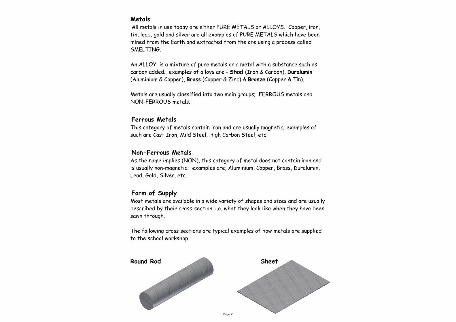
Form of Supply Most metals are available in a wide variety of shapes and sizes and are usually
described by their cross-section. i.e. what they look like when they have been
sawn through.
The following cross sections are typical examples of how metals are supplied
to the school workshop.
Round Rod Sheet

Page 3
Squares Round Tube
Flats Square Tube
Hexagonal Bar Rectangular Tube
Octagonal Bar Angle
Page 4
Metal Working Tools
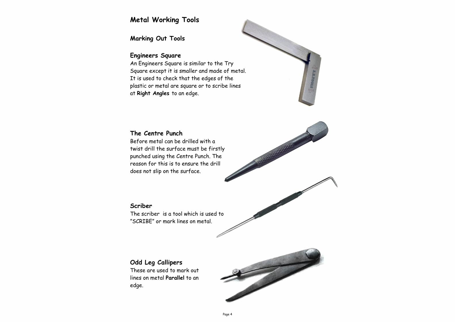
Marking Out Tools
Engineers Square An Engineers Square is similar to the Try
Square except it is smaller and made of metal.
It is used to check that the edges of the
plastic or metal are square or to scribe lines
at Right Angles to an edge.
The Centre Punch
Before metal can be drilled with a
twist drill the surface must be firstly
punched using the Centre Punch. The
reason for this is to ensure the drill
does not slip on the surface.
Scriber The scriber is a tool which is used to
”SCRIBE” or mark lines on metal.
Odd Leg Callipers These are used to mark out
lines on metal Parallel to an
edge.
Page 5
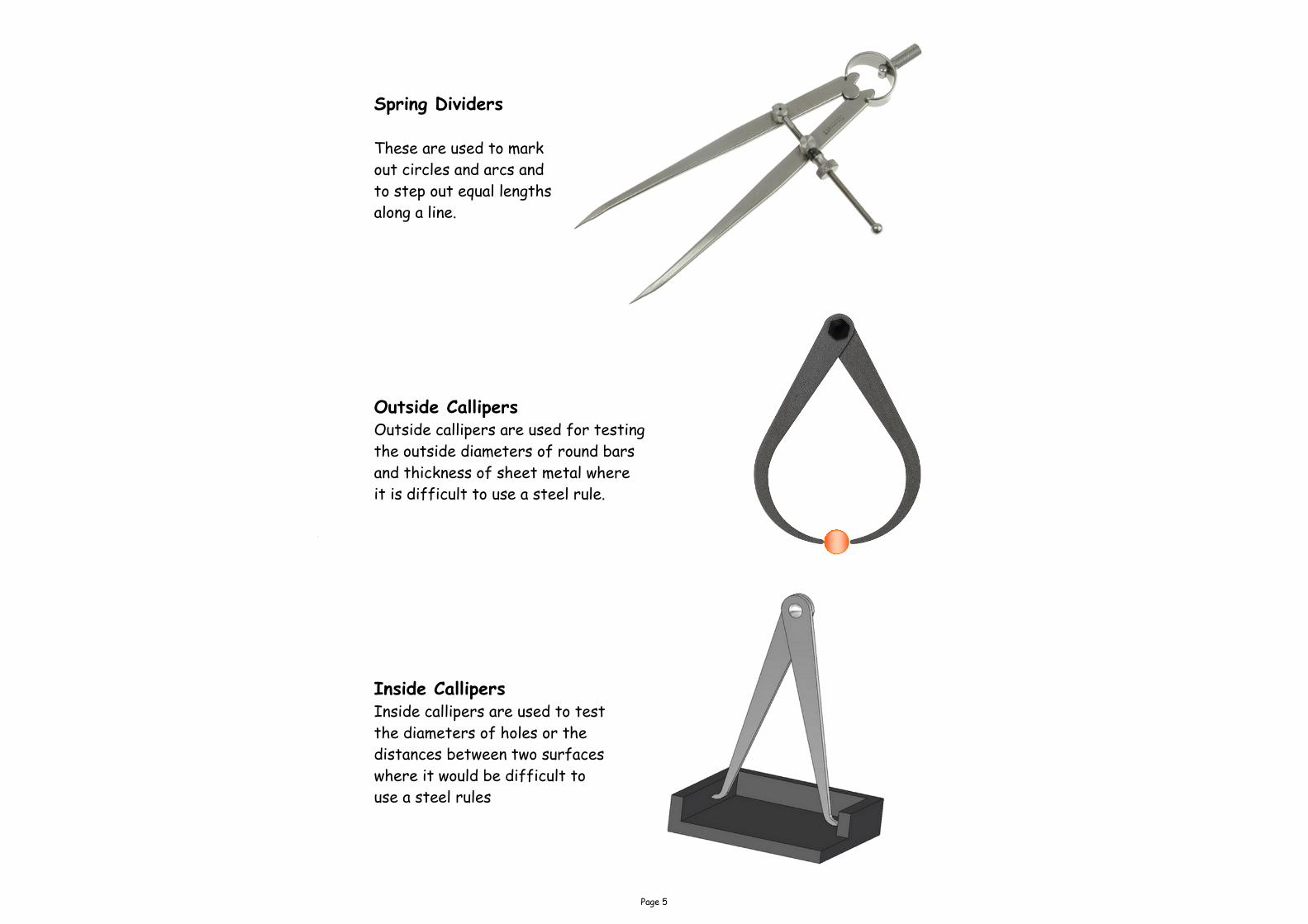
Spring Dividers
These are used to mark
out circles and arcs and
to step out equal lengths
along a line.
Outside Callipers Outside callipers are used for testing
the outside diameters of round bars
and thickness of sheet metal where
it is difficult to use a steel rule.
Inside Callipers
Inside callipers are used to test
the diameters of holes or the
distances between two surfaces
where it would be difficult to
use a steel rules

Page 6
Files
Files are used to shape metal.
They are available in a number of different shapes and degrees of roughness.
Files must not be used without a handle.
Sections of Files (shapes of different types of files)

Page 7
Cross filing In this type of filing the file is
moved across the work piece using
the full length of the blade. This
method of filing is used for removal
of a lot of material with every stroke
applied.
Draw filing In this method of filing, the file is
moved sideways along the work piece
and is used to obtain a smooth finish
after cross filing. This method does
not remove much material.
Cleaning the file Small pieces of aluminium or plastic can
be trapped in between the teeth of the
file. This is called PINNING.
A FILE CARD can be used to clear the
file of the excess material. The file
card looks very similar to a wire brush
except the teeth are very short.
Hacksaw The hacksaw is used for
general cutting of metal bar,
tubes, etc. The blade is easily
removed by slackening or
tightening of the front wing
nut.
Junior Hacksaw This type of saw is also used for
cutting metal but is used for light
work or where a hacksaw is too
clumsy.

Page 8
Raw Hide Mallet This mallet is used when it is
important not to make any
marks on the metal.
Ball Pein Hammer This is a general use hammer
although the ball pein end of the
hammer is used specifically to round
the heads of the snap head rivet.
Portable Electric Drill These drills are usually available in schools
with a maximum chuck capacity of 13mm (i.e.
can hold a drill diam. of 13mm maximum).
Hand Drill The hand drill or WHEEL BRACE is used to
hold and turn twist drills up to 8mm in
diameter. The chuck has three self centring
jaws which securely grip the shank of the
drill.

Page 9
Drills Drills are manufactured from high speed
steel (H.S.S.) or carbon steel and are used
for drilling circular holes in metal, plastic or
wood. The most common type of drills used
are the TWIST DRILLS. These drills have
three basic parts, a point, a parallel body and
a shank which can be either parallel or
tapered.
Countersink Drill/Rose bit A countersunk drill is used to countersink
holes in wood, metal and plastics to allow the
accommodation of a countersunk screw head.
As can be seen from the sketch opposite the
screw will head sit below the surface of the
material.
The Pillar Drill
The pillar drill (or Vertical Drill)
can either be bench mounted or
floor mounted. The chuck (part
which holds the twist drill) can
hold drills up to 13mm in
diameter. The adjustable table
which holds the work piece can
slide up or down and can be locked
at a desirable height.
Safety Check
Before Drilling - ensure the drill
is secure with the chuck key
removed, eye protection on, guard
in position and work piece
securely held.
Page 10
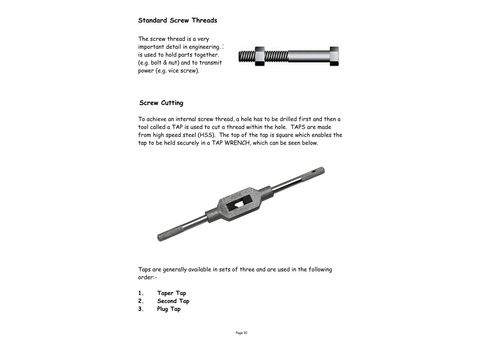
Standard Screw Threads
The screw thread is a very
important detail in engineering. It
is used to hold parts together.
(e.g. bolt & nut) and to transmit
power (e.g. vice screw).
Screw Cutting
To achieve an internal screw thread, a hole has to be drilled first and then a
tool called a TAP is used to cut a thread within the hole. TAPS are made
from high speed steel (HSS). The top of the tap is square which enables the
tap to be held securely in a TAP WRENCH, which can be seen below.
Taps are generally available in sets of three and are used in the following
order:-
1. Taper Tap
2. Second Tap
3. Plug Tap

Page 11
Remember to use the correct cutting
lubricant
Plug Taper Second
As has been mentioned on the previous page,
taps are used in sequential order.
As can be seen in the taps above, the Taper tap
has much smaller teeth at the bottom than the
Second or the Plug taps. This allows the taper
tap to get started by making a shallower thread
cut. The taper cut is followed by the second tap
which has slightly more teeth. Finally, the Plug
tap is used which will make the full thread cut.
1 2 3

Page 12
Screw Dia
Core Dia
The drawing above shows that if a hole was drilled which was the same size
as the threaded bar, the bar would just fall through. The hole which must
be drilled must therefore be smaller in diameter so as to allow the TAP to
cut the threads.
Internal Threading
When tapping a thread in an
internal hole the actual
diameter of the hole to be
drilled must be smaller than
the actual overall size of
the thread to be cut. An
explanation of this is shown
in the sketch opposite.
Hole drilled
to same size
as bar.
Threads cut into metal
Page 13
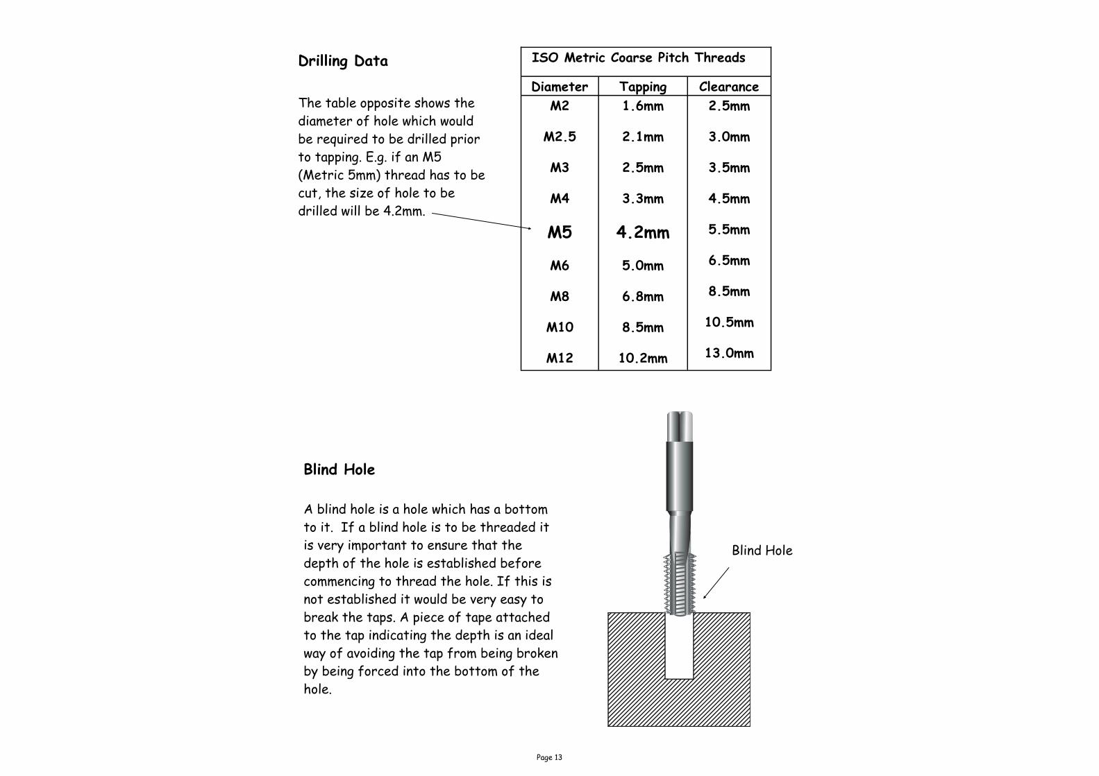
ISO Metric Coarse Pitch Threads
Diameter Tapping Clearance
M2
M2.5
M3
M4
M5
M6
M8
M10
M12
1.6mm
2.1mm
2.5mm
3.3mm
4.2mm
5.0mm
6.8mm
8.5mm
10.2mm
2.5mm
3.0mm
3.5mm
4.5mm
5.5mm
6.5mm
8.5mm
10.5mm
13.0mm
Blind Hole
A blind hole is a hole which has a bottom
to it. If a blind hole is to be threaded it
is very important to ensure that the
depth of the hole is established before
commencing to thread the hole. If this is
not established it would be very easy to
break the taps. A piece of tape attached
to the tap indicating the depth is an ideal
way of avoiding the tap from being broken
by being forced into the bottom of the
hole.
Drilling Data
The table opposite shows the
diameter of hole which would
be required to be drilled prior
to tapping. E.g. if an M5
(Metric 5mm) thread has to be
cut, the size of hole to be
drilled will be 4.2mm.
Blind Hole

Page 14
External Screw Cutting
In the previous few pages internal screw cutting was explored. External
screw cutting will now be investigated. To cut an external thread on a metal
rod a tool called a DIE will be used.
Circular Split Die
The picture opposite shows a split
die, this is the most common type of
die used in the school workshop.
These are used for cutting external
threads. The die is made from high
speed steel (HSS). To assist in
starting the thread cut, the split die
has a split which enables the die to
be opened slightly thus cutting a
shallower cut.
Die Holder or Stock
The circular split die fits into the die stock with the tapered side of the
thread (shown by the writing on the die). The split in the die fits opposite
the centre screw to allow the opening and closing of the die. The two screws
at the side hold the die in the stock To ensure the die can start to create a
thread on the rod the rod must firstly be tapered at the end.

Page 15
Snap Head
Flat Head Pop Rivet
Countersink Rivet
Riveting
Riveting is the process of joining two or more pieces of metal together
permanently. The process uses metal plugs, more commonly known as rivets.
To form the joint, the shank of the rivet is passed through a previously drilled
hole in the components to be joined, it is then cut to size and spread or
shaped, thus preventing the parts from separating. Sketches of the process
are shown overleaf.
Rivets are classified by the shape of the head, their diameter and length.
Common rivet head shapes are round (or snap), countersunk, pan and flat.
Other types of rivet found in the workshop are BIFURCATED and POP
rivets. In general the type of work at hand will determine the type of rivet
to use.
Rivets are made in most types of metal; e.g. mild steel, copper, stainless steel,
brass, aluminium. When using a rivet always ensure that the rivet being used
is the same material as the metals being joined or it will result in aggravated
corrosion at the rivet site.

Page 16
The final stage is to place one riv-
et set into an Engineers vice, place
the rounded head of the rivet in-
to the indent in the rivet set as
shown. Next place the other half
of the rivet set on top of the
shaped head and hit it with a ham-
mer until desired shaped has been
achieved.
The next stage of the operation is to
shape the shank of the rivet to the
approximate shape of the final head
using the Ball Pien hammer.
In the sketch shown opposite the rivet is
placed through the two sheets of metal. The
shank of the rivet is then cut to the desired
length. This length is generally 1.5 times the
diameter of the rivet. E.g. if the diameter of
the rivet is 5mm then the length to be meas-
ured above the sheet metal on the shank will
be 5mm x 1.5 = 7.5mm.
Snap Head Riviting Shank
Rivit set secured in Engineers vice.
Shaped rivit head
Page 17
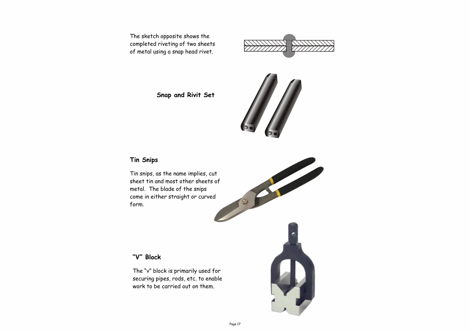
The sketch opposite shows the
completed riveting of two sheets
of metal using a snap head rivet.
Snap and Rivit Set
Tin Snips
Tin snips, as the name implies, cut
sheet tin and most other sheets of
metal. The blade of the snips
come in either straight or curved
form.
“V” Block
The “v” block is primarily used for
securing pipes, rods, etc. to enable
work to be carried out on them.

Page 18
Heat Treatment
When a metal is cold worked, i.e. when it is cut, beaten, hammered, bent,
twisted or shaped, etc. at normal room temperature, tremendous internal
forces are set up within its grain structure and the metal becomes extremely
hard and liable to split. The term ‘heat treatment’ is applied to metals that
undergo some form of heating process in order to change their properties.
Generally, any heating process carried out on a solid metal is referred to as
heat treatment. Heat treatments involve processes such as annealing,
normalising, forging, hardening, tempering, etc.
Work Hardened
If a material has been bent, hammered or twisted consistently over a period
of time the metal will be Work Hardened. What is meant by this, is, the
tiny molecules which make up the metal have been pushed and twisted out of
their original positions thus making the metal very liable to breaking. This
can be fixed by Annealing the metal.
Annealing
This process makes the metal as soft as possible to relieve the internal
stresses, and make it easier to shape. The annealing process generally
involves heating up to a certain temperature and allowing to cool, either in the
air or in water depending on the material being annealed. If soap is applied to
Aluminium prior to heating it will turn Black when the correct temperature
has been reached.
Anvil
Forge

Page 19
Tempering This process involves heating the metal to various temperatures and then
immediately quenching it in water. As the metal is being heated it changes colour
starting with a pale straw to dark straw to reddish brown to purple then dark
blue. Dependant on what properties are required of the steel being tempered will
determines what heat it will be heated to. E.g. when it reaches a dark blue colour
it is at 300o C. These colours are known as TEMPERING COLOURS.
Case Hardening
Mild steel cannot be hardened and tempered as its carbon content is too low.
What can be done is to provide it with a hard outer case. In this process the
metal is heated to a bright red heat and then rolled in a carbon rich powder. The
carbon is absorbed into the skin of the metal thus making it very hard on the
outer skin. This type of metal is ideal for components such as gear wheels which
require to be hard wearing.
Hardening
To enable carbon steel (i.e. tool steel) to be used for the wide variety of tools
and articles that are necessary in the school workshop and in industry it must
first be hardened, then tempered.
Taking a high carbon screwdriver blade for example, this is HARDENED by
heating it slowly to a dull cherry colour and then quenching it in oil or tepid water.
When this part of the process has been carried out, it is unusable. Although it is
very hard it is also very brittle (i.e. it can break very easily). To make the
hardened steel usable it must now be TEMPERED, i.e. given properties such as
toughness, elasticity, strength.
Malleability
This is the ability of a material to withstand being hammered, rolled or bent
without the material breaking.
Ductility
This is the ability of a material to withstand being stretched without the
material breaking.
Page 20
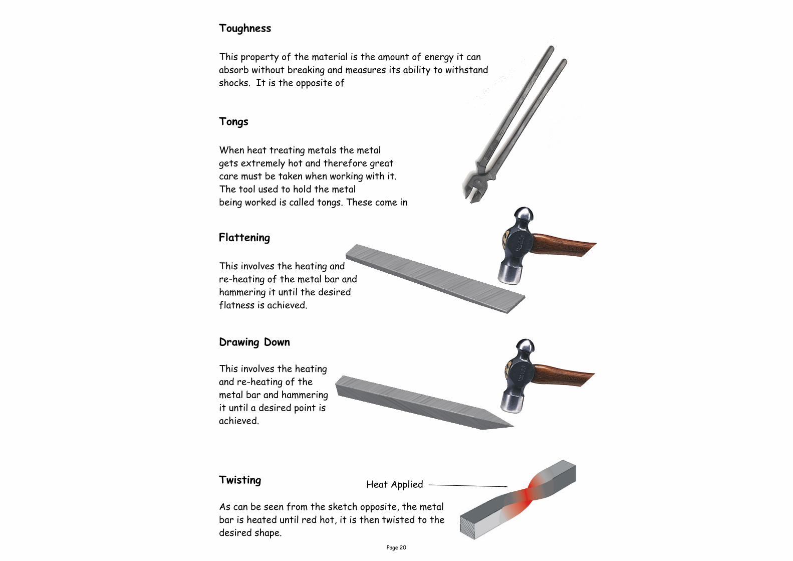
Flattening
This involves the heating and
re-heating of the metal bar and
hammering it until the desired
flatness is achieved.
Twisting
As can be seen from the sketch opposite, the metal
bar is heated until red hot, it is then twisted to the
desired shape.
Drawing Down
This involves the heating
and re-heating of the
metal bar and hammering
it until a desired point is
achieved.
Tongs
When heat treating metals the metal
gets extremely hot and therefore great
care must be taken when working with it.
The tool used to hold the metal
being worked is called tongs. These come in
Heat Applied
Toughness
This property of the material is the amount of energy it can
absorb without breaking and measures its ability to withstand
shocks. It is the opposite of

Page 21
Soldering
Soldering is the process of
permanently joining two pieces of
metal together using a mixture of tin
and lead. Mixing these two metals
reduces the overall melting
temperature enough to melt the
solder using a soldering iron (a heated
piece of metal attached to a handle) .
Brazing
This process is very similar to soldering in
that it uses an alloy heated to it’s melting
temperature to join two pieces of metal
together. When Brazing, the filler metal
used is called BRAZING SPELTER, which is
an alloy of copper and zinc (BRASS). The
heat is generated by the use of a blow torch.
Welding
Welding is the process
of joining two pieces of
metal together using
very high heat and an
additional filler metal.
The filler metal used
must be the same type
of metal being
permanently joined.

Page 22
Resistance Spot Welding
Resistance spot welding, usually
referred to as SPOT WELDING, is the
most widely used of this type of welding.
As shown in the sketch opposite the
overlapping work is positioned between
copper electrodes which have reduced
area tips to produce welds that are
usually from about 1.6mm to 12.5mm in
diameter. After the electrodes are
closed onto the work piece a high
electric current is passed through these
points which fuses (melts) the two pieces
of metal together.
Plastic Dip Coating
If a ferrous metal is left in the
atmosphere for a length of time it
will rust. In order to prevent this
from occurring a barrier has to be
placed between the metal and the
atmosphere. One method of doing
this is protecting the metal with a
plastic coating.
A plastic coating is applied in the following
way:-
1. Thoroughly clean and degrease the metal.
2. Heat the metal to 180o degree C in an oven.
3. Dip the metal into the fluidised plastics
powder for a few seconds.
4. Return it to the oven to fuse the coating to a
smooth glass finish. Leave to cool.
Fluidiser

Page 23
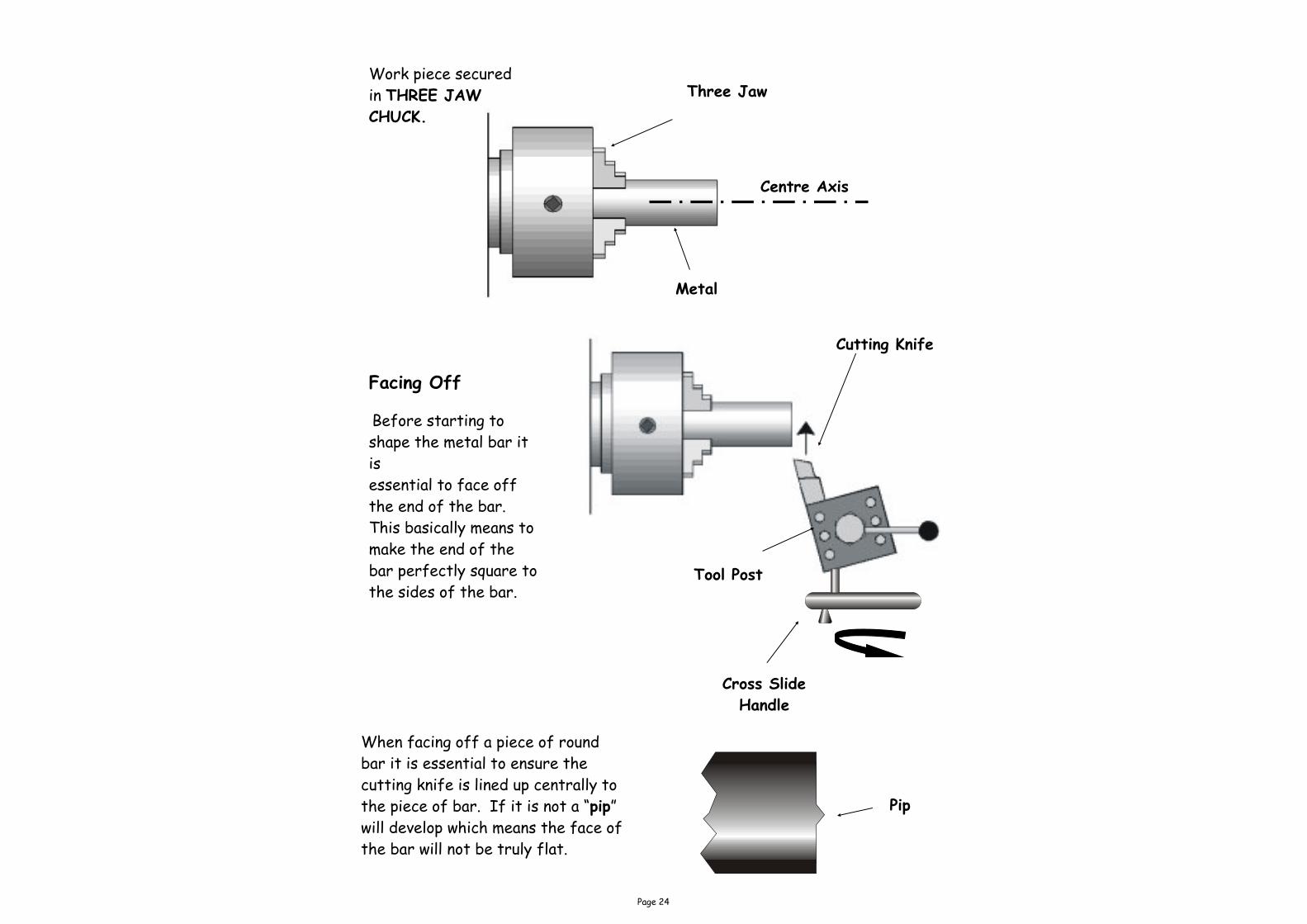
Metal Lathe
The purpose of a metal lathe is to shape metal bar into various desired
shapes. A typical example is the nut & bolt assembly seen earlier in this
booklet. The work piece (metal bar) is secured to a rotating three jaw
chuck. The tools which are made from High Speed Steel (HSS) are secured
in the tool post. An electric motor spins the work piece to which the cutting
tools are then brought into contact with the metal bar.
Three Jaw
Chuck Tailstock
Tool Post
Compound
Slide
Lathe Bed Gear Box Cross Slide
Handle
Saddle
Handle
Head Stock
Page 24
Facing Off
Before starting to
shape the metal bar it
is
essential to face off
the end of the bar.
This basically means to
make the end of the
bar perfectly square to
the sides of the bar.
Tool Post
Cutting Knife
Work piece secured
in THREE JAW
CHUCK.
Metal
Three Jaw
Centre Axis
Cross Slide
Handle
When facing off a piece of round
bar it is essential to ensure the
cutting knife is lined up centrally to
the piece of bar. If it is not a “pip”
will develop which means the face of
the bar will not be truly flat.
Pip

Page 25
Taper Turning
This is where the tool moves along
the bar at an angle moving further
away from the centre axis of the
bar.
Parallel Turning
This technique moves the tool
parallel to the centre axis of the
bar as can be seen from the
drawing.
Parting Off
When all turning work has been
completed the final task is to “Part
Off” (remove the turned piece
from the bar secured in the three
jaw chuck.
Large Saddle Handle
Direction of Cut
Compound Slide Handle

Page 26
Knurling Tool This tool is used to “press”,
NOT cut a straight or diamond
pattern into the metal. The
process is usually done to
provide a hand grip.
Knurled Bar Shown opposite is a bar which has been
“knurled” with a diamond pattern.
Slocombe or Centre Drill This is a drill and countersink combined. It is
used to drill a hole in one end of a piece of bar so
as to accommodate the revolving centre as shown
below. As it is not possible to punch holes prior
to drilling the centre drill is used first.
Shown below are commonly used metal lathe cutting tools.
Parting Tool Round Nose RH Knife LH Knife

Page 27
Finishing The purpose of applying a finish to a piece of metal is to protect it from
tarnishing or corrosion (rusting). Think of a metal artefact (say a bike) was to
be constructed and left outside without any protective coating (paint), how long
do you think it would take before it rusted? Not very long! Therefore metals
have to be protected from rain, snow, etc. There is a number of ways of doing
this depending on the type of metal being protected. The following examples
are just some methods of protecting metals.
Painting Paints are applied to bikes, garden gates, bridges, washing machines, etc be-
cause these artefacts are generally made from steel. Paints are usually applied
this type of metal because they come in various forms and many colours.
Lacquering This is very similar to varnishing, it can be applied with a brush or can be
sprayed on. The purpose of using this type of finish, is, if the base metal has a
nice colour to it e.g. copper or brass, it allows this colour to be seen but at the
same time protecting it.
Bluing This process involves heating the metal up and dipping it in a bath of oil, leaving
it to cool and wiping dry with a cloth.
Revolving Centre The revolving centre is secured in the
tailstock. The bar to be turned is secured
at one end by the chuck and held in place at
the other end using the revolving centre.
The revolving centre allows the bar to
rotate freely allowing turning between
centres.
Jacobs Chuck This tool is placed in the tailstock of the
centre lathe and is used to hold twist
drills.

Page 28
Sand Casting (Moulding)
Sand casting is the process of making metal shapes (components) using
pre-shaped objects and sand. A typical example of an object which has been
cast is the Engineers vice which can be found on the school work benches. This
tool will have been cast in two separate castings.
The bottom part of the casting unit which is called a DRAG is called so because
of the fact that the PATTERN is dragged from the sand. The top half of the
casting unit is called the COPE.
Shown opposite are the Cope & Drag
which will hold the sand and allow
molten metal to flow into.
Stage 1
The COPE and DRAG are both filled with wet sand. The pattern (mould) is then
placed onto the casting board as shown below. The wet sand is then placed
around the mould and packed very tightly. The excess sand is removed from
the top as can be seen.
Cope

Page 29
Stage 2 The two runners are created to
allow the molten metal to flow
into the space created by the
pattern. The sand is also
smooth off using a trowel.
Stage 3 The Drag has now been up righted
and the Cope has been placed on
top as can be seen. Sprue pins are
then pushed through the sand to
produce a RUNNER and a RISER.
The runner will be the channel in
which the molten metal will be
poured into the mould. Vent holes
are also inserted through the sand
to allow excess air and steam to
escape.
Stage 4 At this stage the wooden pattern
has been removed and the riser
and runner which were created by
the sprue pins have also been
removed. This will allow molten
metal to flow through into the
mould.
Pattern or Mould
Page 30
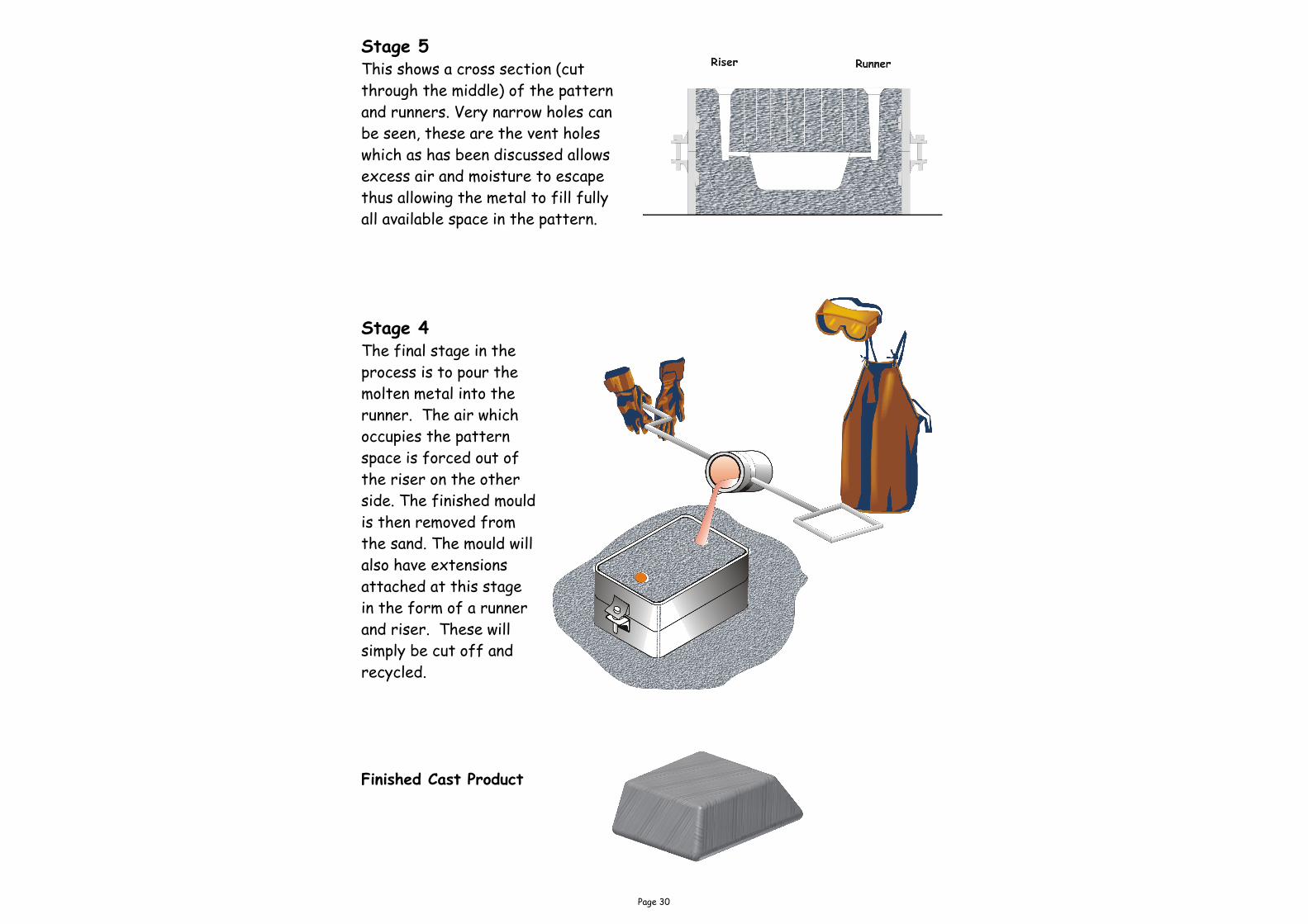
Stage 5 This shows a cross section (cut
through the middle) of the pattern
and runners. Very narrow holes can
be seen, these are the vent holes
which as has been discussed allows
excess air and moisture to escape
thus allowing the metal to fill fully
all available space in the pattern.
Stage 4 The final stage in the
process is to pour the
molten metal into the
runner. The air which
occupies the pattern
space is forced out of
the riser on the other
side. The finished mould
is then removed from
the sand. The mould will
also have extensions
attached at this stage
in the form of a runner
and riser. These will
simply be cut off and
recycled.
Finished Cast Product

Page 31
Micrometer
This tool is used to measure sizes
with great accuracy. The most
commonly used micrometers can
measure to one hundredth of a mm.
The micrometer is generally used
for measuring external sizes.
Vernier Callipers
The vernier callipers are also used
for measuring very accurate sizes
except the vernier calliper can
measure internal sizes, depths and
external sizes.
Folding Bars
The folding bar is used when
folding sheet metal in order to
obtain a straight, neat bend.
They are usually held in a vice
for small scale work.

Page 32
Hand Vice
This is used for holding small
and especially irregular shaped
parts while drilling, riveting etc.
Machine Vice
This type of vice is used to hold
heavier pieces of metal while
drilling. The main body of the
vice has been CAST in a mould.
The handle of the vice has been
KNURLED.
Engineer’s Vice
The vice is bolted to the bench top
so as to ensure the vice does not
move while working on it. The vice is
used primarily to hold metal while
cutting, sawing, filing, etc. are
carried out. As with the machine
vice the body has also been CAST in
two separate pieces.
Toolmaker’s Clamp
These are used to hold parts
together while marking out,
shaping and drilling.