technical data - demag · 2.1 assembling the trolley 10 2.1.1 kbk i, ... 1 technical data 1.1...
TRANSCRIPT
Technical dataDemag D-SH SpeedHoist
203 533 44060510 enEN 714 IS 852
42374245.eps

2 2035
3344
.indd
/060
510
©
Dem
ag C
rane
s &
Com
pone
nts
Gm
bH
Manufacturer Demag Cranes & Components GmbHP.O. Box 67 · 58286 Wetter (Germany)Telephone +49 (0) 2335 92-0 · Telefax +49 (0) 2335 927676www.demagcranes.com
Contents
Part no.:D-SH SpeedHoist operating instructions 211 151 44DC-Pro operating instructions 214 741 44DC-Pro technical data 203 525 44DCS-Pro technical data 203 525 44D-SH Speedhoist brochure 213 054 44D-SH SpeedHoist flyer 213 125 44
Accompanying documents
1 Technical data 31.1 Design overview 31.2 Explanation of size designation 31.3 Selection table 31.4 Hoist motor data 31.5 Dimensions 41.6 Control units 81.7 Part numbers 92 General data 102.1 Assembling the trolley 102.1.1 KBK I, KBK II, Aluline classic 120 and 180 trolley 102.1.2 CF 5 trolley, flange width 50 – 91 mm with load bar 112.1.3 RU trolley, flange width 50 – 90 mm with load bar 122.2 Suspension heights, rope 132.3 Interface for load handling attachment 132.4 Power supply 152.4.1 Connector protection 152.4.2 Emergency-stop 153 Setting the parameters 173.1 Software terminal brief instructions 173.1.1 Description 173.1.2 Connection 173.2 Operating terminal accessories 183.3 Overview 18
32035
3344
.indd
/060
510
©
Dem
ag C
rane
s &
Com
pone
nts
Gm
bH
1 Technical data
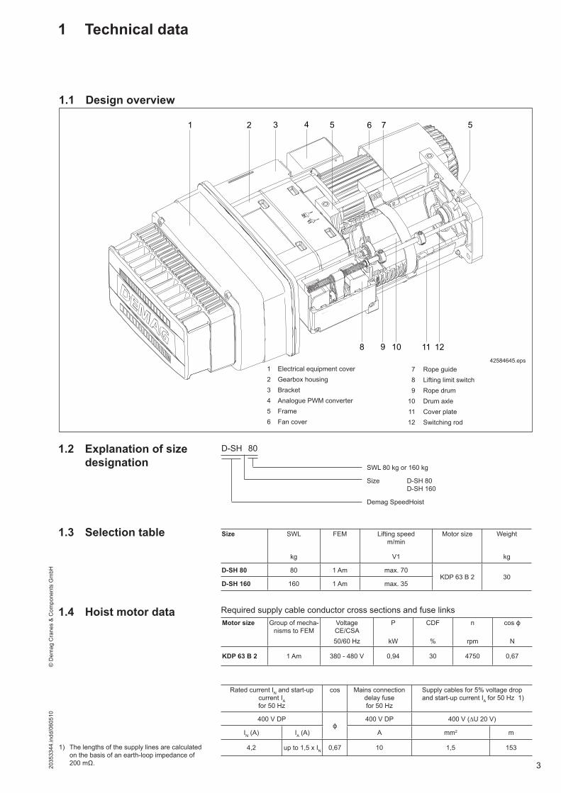
1.1 Design overview
1.2 Explanation of size designation
1.4 Hoist motor data
1.3 Selection table
D-SH 80
SWL 80 kg or 160 kg
Size D-SH 80 D-SH 160
Demag SpeedHoist
Required supply cable conductor cross sections and fuse links
Rated current IN and start-up current IAfor 50 Hz
cos Mains connection delay fusefor 50 Hz
Supply cables for 5% voltage drop and start-up current IA for 50 Hz 1)
400 V DPϕ
400 V DP 400 V (∆U 20 V)
IN (A) IA (A) A mm2 m
4,2 up to 1,5 x IN 0,67 10 1,5 1531) The lengths of the supply lines are calculated on the basis of an earth-loop impedance of 200 mΩ.
1 2 5 6 5
8 9 10 11 12
73 4
1 Electrical equipment cover2 Gearbox housing3 Bracket4 Analogue PWM converter5 Frame6 Fan cover
7 Rope guide 8 Lifting limit switch 9 Rope drum 10 Drum axle 11 Cover plate 12 Switching rod
42584645.eps
Size SWL FEM Lifting speedm/min
Motor size Weight
kg V1 kg
D-SH 80 80 1 Am max. 70KDP 63 B 2 30
D-SH 160 160 1 Am max. 35
Motor size Group of mecha-nisms to FEM
VoltageCE/CSA
P CDF n cos ϕ
50/60 Hz kW % rpm N
KDP 63 B 2 1 Am 380 - 480 V 0,94 30 4750 0,67

4 2035
3344
.indd
/060
510
©
Dem
ag C
rane
s &
Com
pone
nts
Gm
bH
1.5 Dimensions
39
366 215
640
15
143
164
307
105
M8
93
45
ø20
15
70
150
215
105
M8
355
203
188
152
42586146.eps
Rope outlet lowest hook position
Rope outlet highest hook position
1)
1) Load bar for KBK trolleys, optional, part no. 851 195 44

52035
3344
.indd
/060
510
©
Dem
ag C
rane
s &
Com
pone
nts
Gm
bH
45
9315
0
90
355
m/n
853
850
D-SH hoist with two KBK I or KBK II trolleys and manual force control1/1 reevingSWL 80 kg KBK I
42586247.eps
Size Reeving Hook path Foot hole distance
Highest hook position
Lowest hook position
m m n
D-SH 801/1 2,2 39 93
D-SH 160
Load bar
Load bar, part no.: 851 195 44
Rope travelm = highestn = lowesthook position
The D-SH hoist with D-Grip should not be used in connection with a conductor line integrated in the KBK rail, since the manual force required for the D-SH hoist with D-Grip is lower than the force required for displacing the current collector.
Note:
6 2035
3344
.indd
/060
510
©
Dem
ag C
rane
s &
Com
pone
nts
Gm
bH
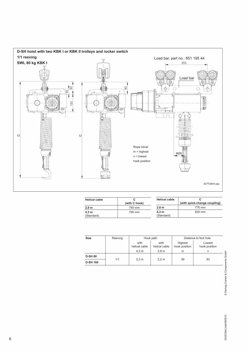
42772844.eps
Helical cable C(with C hook)
2,8 m 745 mm4,3 m (Standard)
795 mm
Helical cable C (with quick-change coupling)
2,8 m 770 mm4,3 m (Standard)
820 mm
Size Reeving Hook path Distance to foot holewith
helical cable 4,3 m
with helical cable
2,8 m
Highest hook position
m
Lowest hook position
n
D-SH 801/1 2,2 m 2,2 m 39 93
D-SH 160
4593
150
90
355
m/n
CC
D-SH hoist with two KBK I or KBK II trolleys and rocker switch1/1 reevingSWL 80 kg KBK I
Rope travelm = highestn = lowesthook position
Load bar, part no.: 851 195 44
Load bar

72035
3344
.indd
/060
510
©
Dem
ag C
rane
s &
Com
pone
nts
Gm
bH
45
9315
0
90
355
m/n
755
823
D-SH hoist with two KBK I or KBK II trolleys and DSM Manulift handle1/1 reevingSWL 80 kg KBK I
42772944.eps
Size Reeving Hook path Foot hole distance
Highest hook position
Lowest hook position
m m n
D-SH 801/1 2,2 39 93
D-SH 160
Load bar
Load bar, part no.: 851 195 44
Rope travelm = highestn = lowesthook position

8 2035
3344
.indd
/060
510
©
Dem
ag C
rane
s &
Com
pone
nts
Gm
bH
D-Grip with quick-change coupling
Rocker switch with quick-change coupling
Quick-change coupling
Light barrier
Right-angle plug
Left button Right button
“Grip occupied” display
Status LED
Emergency-stop button
Switching rocker
Quick-change coupling
1.6 Control units
42375644.eps
42534244.eps

92035
3344
.indd
/060
510
©
Dem
ag C
rane
s &
Com
pone
nts
Gm
bH
1 DSM Manulift 2 Top cover 3 Emergency-stop switch 4 Actuating rockers 5 Quick-change coupling
0 1
9
40215744.eps
1
2
44
5
3
DSM Manulift quick-change coupling
1.7 Part numbers Part no. Designa-tion
Control Operating voltage [V]
Frequency [Hz]
Remark
929 005 46
D-SH 80
Rocker sw. quick-change coupl.
380 - 480 50 / 60
929 004 46 Rocker sw. C hook
929 012 46 Manulift quick-change coupl.
929 000 46 D-Grip Emerg. stop, external
929 009 46 Rocker sw. quick-change coupl.
USA design929 008 46 Rocker sw. C hook
929 014 46 Manulift quick-change coupl.
929 002 46 D-Grip USA emerg. stop, external
929 007 46
D-SH 160
Rocker sw. quick-change coupl.
380 - 480 50 / 60
929 006 46 Rocker sw. C hook
929 013 46 Manulift quick-change coupl.
929 001 46 D-Grip Emerg. stop, external
929 011 46 Rocker sw. quick-change coupl.
USA design929 010 46 Rocker sw. C hook
929 015 46 Manulift quick-change coupl.
929 003 46 D-Grip USA emerg. stop, external
Rocker switch with C hook
Emergency-stop button
Switching rocker
Load hook
42376144.eps

10 2035
3344
.indd
/060
510
©
Dem
ag C
rane
s &
Com
pone
nts
Gm
bH
The D-SH can either be mounted using the threaded bore holes of the housing flange or by connecting it to a load bar (see below).
1 1
41401044.eps41400944.eps
KBK I trolley with pin KBK II trolley with pin
Aluline classic 120 trolley with pin
11
Aluline classic 180 trolley with pin
2.1 Assembling the trolley2.1.1 KBK I, KBK II, Aluline classic
120 and 180 trolley
42783044.eps
2
1
2
6
7
1
3
3
2 34
5
9
9
88
42589744.eps
42589844.eps
1 Trolley with pin2 Washer A21 x 37 x 33 Washer 20 x 32 x 4 KBK I and KBK II4 Tube 20 x 2 x 22 KBK I5 Load bar
6 Hex. socket screw M 8 X 227 Washer 8 x 16 x 28 KBK I, KBK II, Aluline classic 120 and 180 pins9 BoClip
Tightening torque 25 Nm
2 General data

112035
3344
.indd
/060
510
©
Dem
ag C
rane
s &
Com
pone
nts
Gm
bH
3
4
8
21
5
6
7
2.1.2 CF 5 trolley, flange width 50 – 91 mm with load bar
41665545.eps
11
1
9
1
108
7
42783144.eps
1 CF 5 click-fit trolley2 Retaining clip SL 10 SXN083 CF5 retaining elements4 Head pin 10 x 64,8 slot5 Tube 16 x 2,8 x 296 CF5 suspension eye bracket
7 Head pin 12H11 x 30 slot8 Retaining clip SL 12 SXN089 CF5 trolley crossbar10 Hex. socket screw M 8 x 2211 Washer 8 x 16 x 2
Tightening torque 25 Nm

12 2035
3344
.indd
/060
510
©
Dem
ag C
rane
s &
Com
pone
nts
Gm
bH
2.1.3 RU trolley, flange width 50 – 90 mm with load bar
41665744.eps
42783244.eps
2
2
12
3
13
2 Side cheek travel wheel univ. no toothed rim3 D-SH load bar4 Load capacity plate 450 kg5 RU 3DK travel wheel universal6 Sleeve 12,1 x 27 x 97 Hex. nut M16 x1,5
8 Washer 16,5X 25 X 49 Load bar RU 3 cpl. (items 7, 8, 10, 11)10 Pin RU 3 load bar11 Tube 26,9 x 2,65 x 3112 Hex. socket screw M 8 X 2213 Washer 8 x 16 x 2
Tightening torque 25 Nm
Tightening torque 50 Nm
Tightening torque 50 Nm
132035
3344
.indd
/060
510
©
Dem
ag C
rane
s &
Com
pone
nts
Gm
bH
2.2 Suspension heights, rope
The standard rope length of the D-SH is 11 m including the safety windings on the rope drum. The rope length is divided into 1,25 m of safety windings which always remain on the drum, 2,2 m max. hook path and 7,5 m of dead rope.The standard rope length of the D-SH is 11 m including the safety windings on the rope drum. The length is divided into 1,3 m of safety windings which always remain on the drum, 2,2 m max. hook path and 7,5 m of dead rope. The rope is an easily bending rope, particularly suitable if the rope is to be returned via additional rope sheaves.If larger rope lengths are required, a longer rope can be ordered for this specific application (please state when ordering).A special stainless steel rope is also available (requires shorter maintenance inter-vals). All ropes measure 5 mm in diameter.The manual force control system is provided with a helical cable, standard length 2,8 m (extended), for transmitting the electrical signals of the D-Grip unit. This limits the suspension height to max. 3,8 m from the lower edge of the travel rail. Larger suspension heights require a special helical cable which must be specified additionally in your order (please specify suspension height). Shortening the helical cable will not result in a reduction of the C dimension.The rocker switch as well as the DSM Manulift are supplied with a helical cable having a standard length of 4,3 m (extended). This results in a max. suspension height of approx. 5 m – from the lower edge of the travel rail.For a C dimension reduced by approx. 50 mm, a helical cable with a length of ap-prox. 2,8 m (extended) is also available.
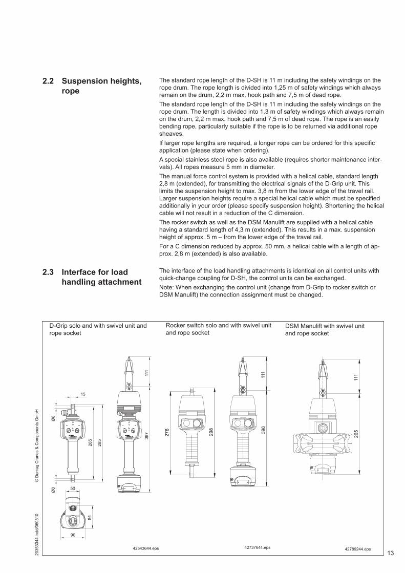
The interface of the load handling attachments is identical on all control units with quick-change coupling for D-SH, the control units can be exchanged.Note: When exchanging the control unit (change from D-Grip to rocker switch or DSM Manulift) the connection assignment must be changed.
2.3 Interface for load handling attachment
D-Grip solo and with swivel unit and rope socket
42543644.eps
111
387
285
265
Ø8
Ø8
84
15
90
50
276
298
398
111
Rocker switch solo and with swivel unit and rope socket
42737644.eps
265
111
DSM Manulift with swivel unit and rope socket
42789244.eps

14 2035
3344
.indd
/060
510
©
Dem
ag C
rane
s &
Com
pone
nts
Gm
bH
For the quick-change coupling on D-Grip, rocker switch or DSM Manulift the load handling attachments known from the Demag DC chain hoist range are available (see DSM Manulift example below).The elements can be connected at the bottom of the individual D-Grip, rocker switch or DSM Manulift units.For further load handling attachments for the quick-change coupling see Demag DC chain hoist technical data 203 525 44.
Load handling attachment on DSM Manulift, example
265
111
158
9570
17
7125
122,8
15,5
26
74,5
Ø20
M12
50
10,5
85
Item 1 2 3 4 5 6 7 8
42789344.eps
Item Designation Description SWL Part no. Weight[kg] [kg]
1 Open hook125
565 695 44 0,6512 Belt sling Belt sling width 45 mm, max. dia. to be gripped 430 mm 565 696 44 -
3 Crane hook adapter with quick-change coupling
The adapter for the crane hook also makes it possible to use Manulift load handling attachments on other hoists.
718 332 450,950
250
718 333 454 Load hook Included in the standard scope of delivery 835 665 44 0,3175 Swivelling load hook 835 584 44 0,6086 Coupling pin For fitting individual load handling attachments 835 580 44 0,084
7 Manulift articulated joint The articulated joint prevents the chain from twisting between the chain hoist and the Manulift control unit. 835 669 44 0,324
8 Pantograph tongs swivel adapter The swivel adapter for SZ 1 + 2 pantograph tongs enables the tongs to be turned freely on the DSM Manulift. 717 330 45 0,419
Coupling pin 250 kg
Gripper hook 125 kg
Belt sling 125 kg
Swivelling load hook 250 kg

152035
3344
.indd
/060
510
©
Dem
ag C
rane
s &
Com
pone
nts
Gm
bH
2.4 Power supply Voltage (CE/CSA)380 V – 480 V AC 3-phase, 50/60 Hz. USA 460 V 60 Hz.
A protective plate is available for the D-Grip (part no. 773 235 44), which protects the right-angle plug against damage. The protective plate is galvanized.
Protective plate (option)
42540844.eps
2.4.1 Connector protection
If D-SH hoists are provided with rocker switch or DSM Manulift, no external emer-gency stop is required. The emergency-stop button is integrated in the rocker switch or the DSM Manulift.
2.4.2 Emergency-stop
(1)
40215745.eps42707744.jpg

16 2035
3344
.indd
/060
510
©
Dem
ag C
rane
s &
Com
pone
nts
Gm
bH
Select one of the following alternatives:a) Emergency stop via surface switch Part no.: 792 407 44b) The emergency stop device is provided by the customer and integrated in the
installation
For operation of the D-SH hoist with the D-Grip, an external emergency-stop de-vice must be provided. It is applied on terminals X2.1 and X2.2 in the analogue PWM converter of the D-SH.It is useful to determine the position of the emergency stop device in line with the specific system, e.g. integrated in the operating elements of a load handling at-tachment or of a lifting mast.
42777444.eps
• D-Grip• Rocker switch• DSM Manulift
Inverter
Control board
FanMotor
BrakePulse generator
Lifting limit switch
Lowering limit switch
Externalemergency stop 1)
1) only for D-Grip. The emergency stop is integrated in the control unit when a rocker switch or the DSM Manulift handle is fitted.
2) only for D-Grip
Analogue PWM converter 2)

172035
3344
.indd
/060
510
©
Dem
ag C
rane
s &
Com
pone
nts
Gm
bH
3 Setting the parameters
3.1 Software terminal quick-step instructions
3.1.1 Description
3.1.2 Connection
42738344.jpg
The default parameters are selected so that the SpeedHoist is ready for operation.In many applications, this may already be the optimum setting.In addition, the D-SH features two different possibilities of setting parameters to adapt the SpeedHoist to specific applications.Further parameters may be changed and/or system statuses and operating data may be recorded by means of the parameter setting set (720 905 45), also avail-able as an option, in conjunction with a laptop or via the manual operating terminal (537 414 84).Setting parameters via a laptop or the manual operating terminal may only be car-ried out by instructed specialist personnel.The parameter setting set (part no. 720 905 45) comprises:• RJ12 modular cable (5 m),• RJ12/DSUB9 adapter (blue dot) for PC / laptop,• RJ12/DSUB9 adapter (red dot) for operating terminal,• CD-ROM with Softterm program.
For setting the parameters of the D-SH you will need a PC / laptop. A further possibility of setting the parameters is provided by our operating terminal UPBT2-A00 from our accessories. See section 3.2
The program is controlled by the mouse or the keyboard.
18 2035
3344
.indd
/060
510
©
Dem
ag C
rane
s &
Com
pone
nts
Gm
bH
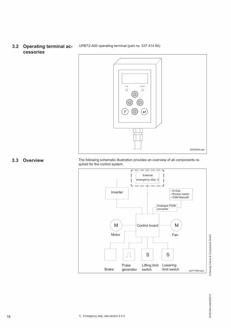
3.2 Operating terminal ac-cessories
42520944.eps
RUN ERROR
F
The following schematic illustration provides an overview of all components re-quired for the control system.
3.3 Overview
1) Emergency stop, see section 2.4.2
42777444.eps
• D-Grip• Rocker switch• DSM Manulift
Inverter
Control board
FanMotor
BrakePulse generator
Lifting limit switch
Lowering limit switch
Externalemergency stop 1)
Analogue PWM converter
UPBT2-A00 operating terminal (part no. 537 414 84)

192035
3344
.indd
/060
510
©
Dem
ag C
rane
s &
Com
pone
nts
Gm
bH

Demag Cranes & Components GmbHP.O. Box 67 · 58286 Wetter (Germany)Telephone +49 (0) 2335 92-0 · Telefax +49 (0) 2335 927676www.demagcranes.com
Prin
ted
in G
erm
any
Reproduction in whole or in part only with prior consent of Demag Cranes & Components GmbH, 58286 Wetter (Germany) Subject to change. Not liable for errors or omissions.
The current addresses of the sales offices in Germany and the subsidiaries and agen-cies worldwide can be found on the Demag Cranes & Components homepage atwww.demagcranes.com/Contact and Demag worldwide