tech notes ., .. @ - nps.gov homepage (u.s. national park ... · pdf fileintroduction while...
TRANSCRIPT

Introduction
While non-destructive evaluation (NDE) techniques have been applied to historic preservation projects in Europe as well as in other countries for many years, their use in the United States has been relatively limited. Most of the American literature about NDE is in the fields of manufacturing and civil engineering works. In manufacturing, for example, dye penetrant tests, x-ray analysis, and ultrasonic techniques aid the evaluation of welds in pipes and pressure vessels. Civil engineers use impact echo testing for the evaluation of concrete bridge decks; ultrasonic methods to determine steel thicknesses in other bridge elements; and electromagnetic equipment to
verify the placement of reinforcing bars in concrete structures.
NDE techniques now need to be recognized for their potential value to engineers and architects who work on historic structures. Historic construction hidden from view may be successfully understood and conditions assessed while minimizing destructive probe work. The data obtained from conventional probe techniques are generally more limited in accuracy because the data is collected at discrete locations and must be interpolated to estimate the conditions at points between the probes. While it may not be possible to eliminate completely the use of conventional-
PRESERVATION
Tech Notes ., .. " @ u.s. Department of the Interior 'l ~~'\ ~ NatIOnal Park Service ; . _ Cultural Resources
-.: Hentage Preservation Services
MASONRY NUMBER 4
Non-destructive Evaluation Techniques for Masonry Construction
Marilyn E. Kaplan Preservation Architecture
Marie Ennis, P.E. Einhorn Yaffee Prescott Architecture & Engineering, P.C.
Edmund P. Meade, P.E. Robert Silman Associates, P.e.
Non-destructive evaluation techniques can be of significant value in historic preservation projects.

Non-Destructive Evaluation(NDE) Techniques
RadarlImpulse Radar: Electomagnetic waves in the band from 50 megahertz to 1.5 megahertz are pulsed into a material by means of a transducer and read by an antenna receiver. In this technique, the receiver reads signals reflected off changes in materials, voids, or buried objects. The raw output display shows the velocity at which the transducer is moved across the surface as the horizontal axis. The vertical axis is the time, in nanoseconds, required for the waves to travel through the material, reflect off an anomaly, and be picked up by the receiver. Access to both sides of the test material is not required.
Impact Echo: A sophisticated version of "sounding" a material enables the user to make judgments about internal conditions. This technique involves a hammer striking a masonry surface, with a receiving transducer located near the striking point. The hammer and receiver are wired to a computer that records the input energy from the hammer and the reflected compression wave energy from the receiver. The output is processed by computer using Fast Fourier Transform operations to produce a frequency domain display where reflections (or echoes) are seen as peaks in the wave signals. This technique has been used extensively to locate voids and defects in concrete slabs and bridge decks. With regard to overall soundness of the masonry, generally speaking, the denser the material, the higher the wave velocity response. It should be noted that this is a qualitative measurement that is useful in surveys for comparative purposes. The thickness of a material can be readily determined if the characteristic wave velocity is known (see Ultrasonic Pulse Velocity, below).
Ultrasonic Pulse Velocity: Also referred to as pulse velocity, this is a standard ASTM test for assessing concrete (ASTM C597-83). This technique uses a transmitter and
2
receiver to pass ultrasonic energy (frequency greater than 20 megahertz) directly through test material. In general, the faster the velocity, the denser the material. If certain engineering properties of the material are known, such as the modulus of elasticity, other mechanical properties can be empirically computed. This technique is also useful for obtaining characteristic wave velocities for various sound masonry materials that can be used in conjunction with other tests, such as impact echo and spectral analysis of surface waves. Accessibility to both sides of the material is required.
Spectral Analysis of Surface Waves: This seismic NDE method was developed to read shear wave velocities and modulus profiles in layered systems, such as pavements and earth where access to the material is only available on one side. It is useful for tasks such as locating delarninations parallel to the surface, and measuring the thickness of a slab on grade or the thickness of multiple layers.
Since identical equipment is used for the spectral analysis of surface waves and impact echo techniques, the two tests are often undertaken in concert. The surface of the test material is struck with a hammer at a point adjacent to two receivers (versus one point for impact echo). As with ultra pulse velocity, the higher the measured velocity, the higher the material modulus and, thus, the better the quality of the masonry. The information provided is qualitative; transformation of the wave data into the frequency domain user Fast Fourier Transform methods provides information more closely related to other mechanical properties of the test material.
Electromagnetic Detection: Commonly used for locating rebar, this technique involves passing an alternating current through a coil to generate a magnetic field. When a magnetic material is encountered,
the field is disturbed. The magnitude is related to the size of the object and proximity to the probe. This NDE technique is recommended for use in conjunction with other techniques to determine the presence of hidden metallic objects.
Infrared Thermography: Also known as heat imagery, this method has often been used to perform energy efficiency studies of buildings, and to evaluate roofing membranes. The operating principle is that an object having a temperature above absolute zero will radiate electromagnetic waves. Wavelengths fall within certain bands, depending on temperature. Wavelengths at room temperature are outside the visible spectrum, while those at very high temperatures are shorter and fall within the visible spectrum. Cameras or video equipment are used to photograph the surface temperature of the subject. The resulting photograph or video images indicate surface temperature variations, which are also affected by ambient humidity, time of day, and other micro-environmental factors. In masonry construction, the different wavelengths often indicate the presence of moisture. The technique can distinguish between dense and porous or deteriorated masonry, as well as identifying voids in walls, such as flues.
Fiber Optics: This technique allows the viewing of the interior of inaccessible areas by inserting a fiberscope (a bundle of flexible optical fibers) or a borescope (a bundle of rigid optical fibers) into the void. Both carry the high intensity light along their length. Some manufacturers have coordinating lines between their "structure scopes" and optional camera equipment. While the technique is marginally useful for solid masonry structures with limited voids, it has been used successfully on masonry cavity wall construction.

contiued from page 1 methods to confirm data, the amount of invasive work can be minimized by the implementation of NDE within historic preservation projects.
NDE techniques are particularly useful in historic preservation because original structural drawings are often unavailable or are deficient in detail and do not reflect "as built" conditions. The location and size of framing members and load bearing elements can usually be determined through NDE. The condition and integrity of a building's structural members can also be determined with the aid of NDE techniques, thus avoiding destructive probe methods, such as test pits, material removal, and core drilling. This is important since conventional probing not only destroys historic fabric, it can be disruptive to the users of the building, and often requires some degree of repair work to reinstate the previous appearance and integrity of the affected building component.
NDE techniques available for use on historic masonry structures include radar (also referred to as impulse radar), impact echo, ultrasonic pulse velocity, spectral analysis of surface waves, electromagnetic detection, infrared thermography and fiber optics. Recent work on the New York State Capitol and on Whig Hall at Princeton University (detailed in the two case studies that follow) demonstrates the practical application of NDE in historic preservation projects.
THE NEW YORK STATE CAPITOL Albany, New York
The New York State Capitol, constructed between 1867 and 1899, is an opulent masterpiece of the late nineteenth century, and one of the last American monumental load bearing structures (see figure J) . Begun by Thomas Fuller in 1867, construction continued until 1876 when appropriations ran out. The next year, construction resumed under the direction of a design advisory board composed of Henry Hobson Richardson, Frederick Law Olmsted, Leopold Eidlitz, and Isaac Perry, the first New York State Architect. Extraordinary care was taken in every aspect of its design, and more than $25 million was spent on construction. In 1979, the structure was designated a National Historic Landmark by the U.S. Department of the Interior.
Problem
The 400 by 300 foot granite structure is
Figure 1. At the New York State Capitol in Albany, New York, non-destructive evaluation techniques were used to determine existing structural conditions and to locate hidden structural elements. Most construction documents had been lost in an early 20th century fire; data collected through non-destructive evaluation served to re-create the structural drawings. Photo: Marie Ennis, P.E.
5 stories tall, with a full basement and attic. Although basement foundation walls up to 16-feet thick support the 200,000 ton building load, the Capitol has suffered significant structural problems since construction. The building load is spread unequally over the foundation, and the site contains layers of local clay mixed with sand and water, which is susceptible to liquefaction. When these conditions were discovered during the initial excavation, the idea of using wood pilings was abandoned and a 3-foot thick unreinforced concrete slab was placed over the excavation to support stepped stone footing for walls and piers.
By 1990, the Commission for the Restoration of the Capitol determined that a comprehensive structural documentation of the building was essential to its long-term preservation. Original structural drawings did not exist, and most construction records were lost in a 1911 fire.
This new study would determine at what locations the subsurface clay was being overloaded; help explain and document the sources of previous failures in the building; identify those areas where code-required alterations, such as new fire stairs, would be best located; and enable the Commission to develop appropriate responses to ongoing requests for additional mezzanines and storage areas.
Evaluation of the Capitol Using NDE Techniques
Robert Silman Associates, P.e. , was retained in 1991 to produce a structural analysis of the northwest quadrant of the
Capitol, and a feasibility study that would explore the potential of the building to absorb additional live loads. The project would involve preparation of structural drawings documenting the size, location and type of structural components. An unusual aspect of the work was a research component to correlate results of NDE techniques with conventional destructive probe methods. If NDE techniques could be successfully applied, damage to the building and disruption to its occupants could be minimized in analysis of the other parts of the Capitol.
The U.S. Army Construction Engineering Research Laboratory assisted in the research by providing staff and equipment through its Construction Productivity Advancement Research Program. By employing NDE in the same areas that would subsequently be opened with destructive probes, the research team intended to show the practical applications of NDE techniques, and demonstrate the reduced physical damage to historic buildings. NDE would also mean substantial cost savings for the work.
The NDE techniques employed included radar, impact echo, ultrasonic pulse velocity and spectral analysis of surface waves, electromagnetic detection, infrared thermography, and fiber optics. Using these techniques, the work was intended to supplement archival research and a visual survey to locate and assess the conditions of the structural components (beams, girders, columns, and bearing walls). Finally, traditional destructive procedures would take place, as necessary, to confirm findings and to provide a comparative basis for determining how and when NDE techniques could be used in lieu of destructive procedures, and what degree of accuracy was achievable for the techniques tested.
Solution (Test Results)
NDE at the New York State Capitol was undertaken through a cooperative agreement with the U.S. Army Construction Engineering Research Laboratory, under the supervision of Robert Silman Associates. The Laboratory relied on outside consultants to operate and interpret equipment. Approximately ten days of site work were required to survey one quadrant of the building from the basement through the roof.
The NDE techniques utilized at the New York State Capitol were experimental in nature. Because the U.S. Army Construction Engineering Research
3

Figure 2. (a) The floor structure is scanned using impulse radar. An operator is shown, pushing the transducer across the floor surface at a constant speed. (b) The transducer is being pulled, by machine, at a constant speed. Photos: Marie Ennis, P.E.
Figure 3. This is the raw output from a radar scan. The beams, brick arches, and concrete slab have been noted. (x-axis= velocity of transducer; y-axis = wave response time.) Photo: U.S. Army Construction Engineering Research Laboratory.
Laboratory participated in the project as a means to develop the procedures for its own purposes, six techniques were used and evaluated.
Impulse Radar. For the New York State Capitol project, the radar tests successfully located embedded beams, girders, columns, and metal ties/anchors (see figure 2). The readings enabled the investigators to profile brick arches spanning
4
Figure 4. (left) The impact echo equipment includes a hammer, receiver, and water soluble coupling gel and was used to locate a steel column concealed behind the granite facing. Photo: Dennis Sack. (right) Impact echo data is shown on the field computer screen. Photo: Marie Ennis, P.E.
roughly 5 feet between beams, and to locate H-shaped steel columns in masonry walls showing the orientation of the flanges. The tests readily measured the thickness of masonry walls that were well bonded. They were also able to determine the depth-of-cover over beams and girders and brick arches, and the location of voids, pipes and flues in walls up to 2 feet 8 inches thick (see figure 3).
Results were less conclusive for the thick stone footings, where the high water table, large quantities of metal near the surface, and the existence of conductive surfaces (false floors with air spaces below) impacted the ability of the equipment to locate the footings. More than any other technique, the radar penetrated the masonry effectively, and allowed large portions of the Capitol quadrangle to be scanned continuously and quickly. Another very promising aspect of the research done at the
Capitol was the application of the backward propagation imaging method to the acquired data in order to provide a computerized visual image of the hidden structure. Further developments of this system would allow architects and engineers to measure hidden features directly from a plotted image, making the technique more "user friendly."
Impact Echo. Impact echo produced good data for reading wall thicknesses and the integrity of granite and sandstone columns, veneer walls, and brick walls less than two feet thick (see figure 4). While steel columns behind granite facing were located, the orientation of flanges was not discernible. The impact echo test provided excellent results in detecting stone cracking parallel to the surface. Its optimal use was when working with homogenous stone materials; with mUltiple layers of material (example: terrazzo over brick) it did not pro-
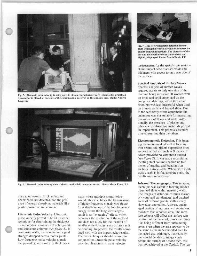
Fig. 5. Ultrasonic pulse velocity is being used to obtain characteristic wave velocities for granite. A transmitter is placed on one side of the column and a receiver on the opposite side. Photo: Andrea Lazarski.
Fig. 6. Ultrasonic pulse velocity data is shown on the field computer screen. Photo: Marie Ennis, P.E.
duce good results. Brick arches and beams were not detected, and the presence of energy absorbing materials like plaster proved an impediment.
Ultrasonic Pulse Velocity. Ultrasonic pulse velocity proved to be an excellent technique for determining the thicknesses and relative soundness of solid granite and sandstone columns (see figure 5). In composite walls, the velocity and signal strength dropped across mortar joints. Low frequency pulse velocity signals can provide good results for thick brick
walls where multiple mortar joints would otherwise block the transmission of higher frequency signals (see figure 6). A disadvantage of the low frequency energy is that the long wavelengths result in an "averaging" effect, which decreases the resolution of the method and does not allow for the location of smaller scale damage, such as brick unit de-bonding. In general, the results correlated well with the impact echo results. The two techniques should be used in conjunction; ultrasonic pulse velocity provides characteristic wave velocity
Fig. 7. This electromagnetic detection instrument is designed to locate rebars in concrete for quality control inspections. The diameter of the bar and the depth·of·cover is calculated and digitally displayed. Photo: Marie Ennis, P.E.
measurement for the specific test material and impact echo assesses voids and thickness with access to only one side of the surface.
Spectral Analysis of Surface Waves. Spectral analysis of surface waves required access to only one side of the material being measured. It worked well on brick and solid stone, and on the composite slab on grade at the cellar floor, but was less successful when used on thinner walls and framed slabs. Due to the sensitivity of the equipment, the technique was not suitable for measuring thicknesses of floors and walls. Additionally, the presence of plaster and other energy absorbing materials proved an impediment. This process was more time consuming than the others.
Electromagnetic Detection. This imaging technique worked well at locating iron beams and girders supporting brick arches that had as much as 9 inches of cover, provided no wire mesh existed (see figure 7). It was also successful at locating steel columns behind up to 8 inches of granite, and locating iron anchors in stone walls. Where wire mesh exists, such as in flat concrete slabs, the results were inconsistent.
Infrared Thermography. This imaging technique was useful in locating hidden pipes and flues within masonry walls. The images of deteriorated brick masonry (water and salt damage) and patched areas of exterior granite walls clearly showed as anomalies. A dense, undamaged portion of masonry will retain less moisture than a porous area. The moisture content will affect the surface temperature of the material, thus identifying it as being different from surrounding areas, even when the area appears to be the same as the undeteriorated area to the naked eye. Although, theoretically, one should be able to image voids behind the surface of a stone face, this was not achieved at the Capitol. The rea-
5

son for this failure is probably related to the sensitivity of the equipment, the wavelength bands being recorded, and high ambient humidity levels during testing. This technique did not prove useful for imaging roof trusses through clay tile roofing.
Fiber Optics. Since the Capitol is a solid masonry building with few voids, the utility of fiber optics in the project was limited. However, it did allow assessment of the interiors of wall chases and flues, including the condition of their mortar joints. It was also used to access the space above decorative hung ceilings; however, the focal length was not sufficient to provide overall views of beams and girders.
Project Summary
Of the NDE techniques employed on this heavy masonry building, radar proved to be the most successful for imaging hidden structure and conditions. Next, in order of success, were impact echo, ultrasonic pulse velocity, spectral analysis of surface waves, and infrared thermography. Electromagnetic detection was very useful, but its scope is limited to buildings that contain some iron or steel and to locations where framing members are isolated from pipes, conduits, and other metal features. Fiber optics was found to be of minimal use in this type of building because of the limited areas where voids were present. One problem to consider is the need to have highly trained equipment operators present, as well as sophisticated computer programs that can translate the raw data into meaningful results. In some cases, despite inherent nondestructive testing costs, the number or conventional probes that can be eliminated will offset these expenses.
WlDGHALL, PRINCETON UNIVERSITY Princeton, New Jersey
Whig Hall is located at Princeton University, in Princeton, New Jersey. An adaptation of a Greek Temple, the two story structure features an entrance portico with full entablature and a simple pediment supported on six fluted marble columns (see figure 8). Along with its adjacent twin, Clio Hall, Whig Hall was constructed of Vermont Montclair Danby Marble and completed in 1893. Designed by A. Page Brown, the building originally housed two rival, campus debating societies.
6
Fig 8. At Princeton University's Whig Hall, almost 100 years of weathering and a fire caused extensive damage to the masonry portico. Originally targeted for replacement, non-destructive testing techniques allowed isolated areas of damage to be evaluated and localized repairs conducted. Photo: Edmund P. Meade, P.E.
Problem
The portico of Whig Hall is primarily constructed of unreinforced, load bearing masonry. Weathering over the past 100 years and a major fire resulted in extensive cracking of the column bases and plinths; sugaring, erosion and pitting of marble surfaces; and erosion of mortar joints Although initial reports commissioned by the university concluded that the portico substructure and columns should be replaced, less intrusive methods of repair were sought.
Evaluation of Whig Hall Using NDE Techniques
Robert Silman Associates, P.e. , was retained in 1994 to evaluate repair alternatives rather than undertaking a total reconstruction. In order to perform a load analysis of the portico structure, it was necessary to document the effective cross section of the columns. A program utilizing NDE techniques was established for both Whig and Clio Hall, although only the results of Whig Hall are presented here. The purpose of this evaluation was to determine the depth , extent, and nature of masonry cracking. Column A of Whig Hall, which measures 22 feet in height and 2 feet, six inches in diameter, appeared to have the most significant cracking. There was considerable concern for the integrity of this column and the unknown nature of the cracks.
Fig. 9. The column capital volutes were cracked and spalled. Photo: Edmund P. Meade, P.E.
Initial condition investigations of the stone elements and the supporting structural members of the portico included a visual examination as part of the survey of the entire exterior of the building. All major elements were examined using "cherry pickers," scaffolding, and ladders. The examination focused on the cracked pieces of stone at the entablature level; the cracked or spalled column capital volutes; the cracked stone columns; the cracked stone column bases and plinths; the deteriorated pieces of masonry that were immediately below or adjacent to the column plinths; and the deteriorated support structure below the portico floors (see figure 9).
At Whig Hall, Column A exhibited severe surface cracking, and an extensive internal crack pattern within the plinths

Fig. 10. The column base and plinths had extensive exterior cracks. The internal column cracks were detected by ultrasonic pulse velocity and impulse radar investigation techniques. Photo: Edmund P. Meade, P.E.
Fig. 11. Impulse radar is being used to eva!~ate both the orientation and depth of cracks vIsIble on the surface of the column shaft. Photo: Edmund P. Meade, P.E.
(see figure 10). Additional cracking was noted at the bases of a number of other column shafts. Some deterioration of the masonry walls beneath the column plinths was also observed, although without signs of differential movement between different portions of the portico foundations.
Following this initial evaluation, the project team, including a stone conserva-
. t ut was anal zed by the geophysicists. Correlations could then be made to !~~·v:~~ ~~~~i~:i:::~:rq~~:'itative eval~ations of the stone. (right) This impulse ~adar !r~nSduce; emits and receives electromagnetic energy. The unit is attached directly to the eqUlpmen s own a left. Photos: Edmund P. Meade, P.E.
tor and stone fabrication specialist, recommended that the column bases and plinths be replaced; the upper portion of the column foundation system be reconstructed; an that localized stone repairs occur where cracks and/or spalls existed.
This repair and restoration plan would require in situ support of the columns and pediment while their bases and. plinths would be replaced and repairs conducted underneath. To better establish a probable scope of work,.a m?re thorough study of the column mtenors was undertaken using ultrasonic pulse velocity and impulse radar investigation. It was hoped that these techniques co~ld more accurately determine areas of faIlure, voids, or other indications of stress.
Solution (Test Results)
NDE was undertaken by a firm specializing in the evaluation of older buildings, G.B. Geotechnics of Cambridge, England. They performed a surve~ of both porticos over a three-day p~flod using a combination of ultraSOnIC pulse velocity and impulse radar (see figure 11). The Whig Hall project benefited from the previous NDE work at the New York State Capitol; however, here, only two tests were determined to be appropriate. Additionally, a single.firm that offered a range of NDE services was used.
Ultrasonic Pulse Velocity. The ultrasonic pulse velocities recorded for the marble were in the range of 0.157 to 0.256 inches per microsecond. In some areas of the column shafts, high amplitude internal reflections were noted, indicative of discontinuities or cracks within the column. The orientation of the various cracks, e.g., horizontal, was identified. The variable depths of the cracks
Fig. 13. The non-destructive evaluatio~ ~f Whig Hall allowed the diagnosis of the condItIon of the masonry and the specification of a relatively low impact repair. Photo: Edmund P. Meade, P.E.
were calculated, with the average maximum depth being about 2 inches.
Impulse Radar. The radar readings indicated that the column shafts were constructed of monolithic marble, with the same type of marble used for the column bases and capitals (see figure 12). The radar detected anomalies near the junctions of the column shaft :vith the base and the capital. The readmgs also indicated that there may be cramps or ties between the columns and the bases/capitals. It could not be determined whether the objects detected were metallic, or if they were possibly "Lewis holes" that had been used to maneuver the stone blocks during construction. Magnetic detection equipment with the ability to penetrate large diameter columns could have been used in conjunction with the radar to verify the nature of the internal anomalies.
Project Summary
The consulting NDE firm provided a written report describing its methodology and findings; it also provided
7

graphics to assist the engineer, architect and conservator in the interpretation of the results.
To help maintain the integrity of the masonry during the repairs, it was recommended that Column A, as well as several areas of other stone elements be pinned. It was necessary to support the column shafts while the bases and plinths were removed. This could be accomplished by the use of high strength steel pins through the column shaft, or the placement of steel clamps around the column shaft to establish a friction hold around the column.
The NDE results indicated areas where pinning or clamping should be avoided, or, if not possible, performed with great accuracy and using extreme care. This would limit the amount of drilling and pinning, techniques that could potentially weaken the columns further (see figure 13). An additional benefit of the NDE work is that it provided a basis of comparison for evaluating other stone elements on the building which exhibited signs of deterioration.
Conclusion
The case studies provided different perspectives on the use of NDE. At the New York State Capitol, the primary purpose was to research nondestructive methods of locating and imaging hidden structure in a massive masonry building. The
research project supplemented information acquired during a visual survey with destructive probe work. At Princeton's Whig Hall, the specification of NDE was part of a contract to assess structural capacities and design repairs, and to prepare construction documents.
The point of the comparison is that there are techniques currently available and experienced firms to perform field investigations, but continued research is needed. Ways to improve the portability and simplify the use of equipment should continue in the manufacturing community. Additional applications and improvement of accuracy for the techniques should be researched through a combination of academic, non-profit research, and commercial organizations. Standards and guidelines need to be developed to aid the architect, engineer, or conservator in the specification of NDE in historic preservation projects. It is hoped that through the combined efforts of preservation professionals, researchers, and equipment manufacturers and operators, that NDE will become generally available and increasingly economical for use on landmark structures. For projects where these techniques should be implemented, the preservation professional must impress upon the client the need for NDE in conjunction with limited conventional probes before beginning project work.
Project Data
New York State Capitol Albany, New York
Structural Engineer: Robert Silman Associates, P.C University Place New York, New York
Consulting Group: U.S. Army Construction Engineering Research Laboratory Champaign, Illinois
Whig Hall Princeton, New Jersey
Architect: Ford Farewell Mills and
Gatsch, Architects 864 Mapleton Road Princeton, New Jersey
Structural Engineer: Robert Silman Associates, P.C 88 University Place New York, New York
Consultant: G.B. Geotechnics Limited Downing Park Swaffham Bulbeck Cambridge, England
This PRESERVATION TECH NOTE was prepared by TECHNICAL PRESERVATION SERVICES, Heritage Preservation Services Division, National Park Service. Charles E. Fisher, serves as Technical Editor of the series. Kay D. Weeks was managing editor of this Tech Note. Dahlia Hernandez, National Park Service, provided helpful administrative support. Special thanks are extended to de Teel Patterson Tiller, Chief, Heritage Preservation Services Division, to Douglas R. Wasama, Ford Farewell Mills and Gatsch, Architects, and to the New York State Commission on the Restoration of the Capitol.
resources. All techniques and practices described herein conform to established National Park Service policies, procedures and standards. This Tech Note was prepared pursuant to the National Historic Preservation Act, as amended, which directs the Secretary of the Interior to develop and make available to government agencies and individuals information concerning professional methods and techniques for the preservation of historic properties.
PRESERVATION TECH NOTES are designed to provide practical information on traditional and innovative techniques for successfully maintaining and preserving cultural
8
Comments on the usefulness of this information are welcomed and should be addressed to Editor, Preservation Tech Notes, Heritage Preservation Services, National Park Service, 1849 C Street NW, Washington, D.C 20240.
ISSN: 0741-9023 PTN-40 September 1997