tecco ® slope stabilization system and ruvolum ® dimensioning method
DESCRIPTION
El exhaustivo estudio "TECCO®" llevado a cabo por Cala Flum Roduner Rüegger Wartmann está ahora disponible en formato para libro electrónico. - En este documento encontrará toda la información sobre la protección flexible de taludes con TECCO® system: comparaciones de productos, métodos de dimensionado, descripción de instalaciones de pruebas realizadas y estudios de casos (solo disponible en inglés).En la actualidad, el nuevo desarrollo de TECCO® SYSTEM3 es la respuesta definitiva de la empresa Geobrugg para la estabilización de la mayoría de los taludes.TRANSCRIPT

TECCO® Slope Stabilization Systemand RUVOLUM® Dimensioning Method
Cała Flum Roduner Rüegger Wartmann
AGH UNIVERSITY OF SCIENCE AND TECHNOLOGY

AGH UNIVERSITY OF SCIENCEAND TECHNOLOGYFaculty of Mining & Geoengineering
TECCO® Slope Stabilization Systemand RUVOLUM® Dimensioning Method
Cała Flum Roduner Rüegger Wartmann
Romanshorn, Switzerland 2012

© 2012 Geobrugg AG, 8590 Romanshorn, SwitzerlandPhone +41 (0)71 466 81 55, www.geobrugg.com, [email protected]
All rights reserved (including those of translations into other languages). No part of thisbook may be reproduced in any form – by photoprinting, microfilm or any other means– nor transmitted or translated into a machine language without written permission fromthe publishers. Registered names, trademarks, etc. used in this book, even when notspecifically marked as such, are not to be considered unprotected by law.
Cover design: Christine Vorndran, Geobrugg AGTotal production: Beltz Bad Langensalza GmbH, Bad Langensalza
ISBN 978-3-033-03296-5Electronic version available.
Pictures on the front page present realized flexible slope stabilizationsystems designed with high tensile steel wire meshes:
Top left: Samsung site Dongcheon, South KoreaTop right: Anzenwil, SwitzerlandBottom left: Túnel do Morro Agudo, Brasil [76]Bottom right: Tokaj Hokurikudo, Gifu Prefecture, Japan

Acknowledgment
The geotechnical, industrial and economical development of the TECCO slope stabilizationsystem, the RUVOLUM dimensioning method as well as its corresponding elements andproducts was supported, co-developed, pushed and driven by various people and conse-quently, our very big thanks go to Bernhard Eicher (inventor of TECCO mesh), XaverPopp, Kaspar Haltiner, Bruno Haller, Andrea Roth, Dr. Roberto Luis Fonseca, Dr. CorinnaWendeler, Hannes Salzmann, Patrick Schwizer, Miroslaw Mrozik, Piotr Baraniak, CarlesRaïmat, Otegui Gabriel Polit, Julio Prieto Fernández, Eberhard Gröner, Aron Vogel, MaxBickel, Roland Bucher, Kazuhito Shimojo, Guido Guasti, Marco Deana, Gabriele Gug-lielmini, Marcel Sennhauser, Erik Rorem, John Kalejta, Steve Mumma, Joseph Bigger,Frank Amend, Maria Soares, Dr. Felipe Gobbi, Javier Temiño, German Fischer, RolandKlein, Jürg Atz, Stefan Haas, Manuel Hungerbühler, Max Bühler and Jörg Bär, as well asmany others; thank you all very much for everything!
Special support for this publication was given by the AGH University of Science and Tech-nology in Krakow (Poland). We would like to thank the Rector of the University, Prof. Dr.A. Tajduś, the Dean of the Faculty of Mining and Geoengineering, Prof. Dr. Czaja andProf. Dr. Waldemar Korzeniowski as well as Prof. Dr. Roman Magda.
Further special thanks go to Prof. Dr.-Ing. L. Wichter from the University of Cottbus (Ger-many), Faculty for Rock and Soil Mechanics for his support and valuable inputs.
Various additional laboratory and field tests, static and dynamic analysis, investigations,supervisions and reports with and around the high tensile steel wire mesh technologies wereexecuted, conducted and/or co-ordinated in Germany, Australia, USA, Japan, Spain andSwitzerland, where we would like to thank very much all the involved people at the TÜVRheinland and LGA Nürnberg (Germany), Rüegger + Flum AG (Switzerland), Universityof Cottbus (Germany), Bergische University of Wuppertal (Germany), Curtin Universityand Kalgoorlie School of Mines (Australia), Washington States University (USA), SwissFederal Institute for Forest, Snow, Landscape WSL (Switzerland), BAREMO GmbH(Switzerland), University of Cantabria (Santander), Institute of Civil and EnvironmentalEngineering at the HSR Hochschule (Rapperswil, Switzerland), TOA GROUT Kogyo Co.LTD (Tokyo, Japan), Luchs und Partner AG (Switzerland), Fatzer AG (Switzerland), Geo-brugg AG (Switzerland) and other Geobrugg subsidiaries as well as many others. Further,we would like to thank Ms. Maryline Spitzli for English spelling and translation review.Last but not least, very special thanks got to the marketing team of Geobrugg Group (espe-cially Urs Brechbühl, Christine Vorndran and Sabrina Frischknecht) for the fine tuning ofthis publication.
Romanshorn (Switzerland), October 2011
Prof. Dr. Marek Cala, AGH University of Science and Technology, CracowDaniel Flum, MSc. (civil) Eng. ETH/SIARudolf Rüegger, MSc. (civil) Eng. ETH/SIAArmin Roduner, MSc. (civil) Eng. Colorado University, USADr. Stephan Wartmann, MSc. (civil) Eng. ETH/SIA; EMBA HSG

IV 4 Überschrift 1

Table of Content
1 Preface . . . . . . . . . . . . . . . . . . . . . . . . . . . . . . . . . . . . . . . . . . 1
2 Introduction . . . . . . . . . . . . . . . . . . . . . . . . . . . . . . . . . . . . . . 3
3 Traditional solutions using wire mesh and wire rope nets . . . . . . . . . . 73.1 Wire mesh as a flexible measure to protect surfaces . . . . . . . . . . . . . . . 73.2 Wire rope nets as a flexible measure to protect surfaces . . . . . . . . . . . . . 83.3 Active and passive systems . . . . . . . . . . . . . . . . . . . . . . . . . . . . . . 93.4 Hard, flexible and soft facing . . . . . . . . . . . . . . . . . . . . . . . . . . . . . 10
4 Traditional dimensioning methods . . . . . . . . . . . . . . . . . . . . . . . . 134.1 Sliding off parallel to the slope . . . . . . . . . . . . . . . . . . . . . . . . . . . . 144.2 Local wedge-shaped bodies liable to break out . . . . . . . . . . . . . . . . . . 154.3 Required input quantities . . . . . . . . . . . . . . . . . . . . . . . . . . . . . . . 174.4 Proof of the terrain’s resistance against sliding (deep sliding surfaces) . . . . 18
5 High tensile steel wire meshes . . . . . . . . . . . . . . . . . . . . . . . . . . . 195.1 High-tensile wire mesh as a slope stabilization system . . . . . . . . . . . . . . 215.2 Nail arrangement . . . . . . . . . . . . . . . . . . . . . . . . . . . . . . . . . . . . 225.3 Pretensioning of the nails . . . . . . . . . . . . . . . . . . . . . . . . . . . . . . . 235.4 High tensile steel wire meshes . . . . . . . . . . . . . . . . . . . . . . . . . . . . 245.5 Material properties of high-tensile wire mesh . . . . . . . . . . . . . . . . . . . 255.5.1 Tensile tests and results on single wire . . . . . . . . . . . . . . . . . . . . . . . 265.5.2 Machinery for the mesh tests in longitudinal and transverse directions . . . . 285.5.3 Test setup and results of tensile test in the longitudinal direction . . . . . . . 315.5.4 Test setup and results of tensile tests in the transverse direction . . . . . . . . 325.6 Corrosion protection . . . . . . . . . . . . . . . . . . . . . . . . . . . . . . . . . . 345.6.1 Accelerated weathering tests . . . . . . . . . . . . . . . . . . . . . . . . . . . . . 355.6.2 Long-term field tests for comparison between Zn coated and Zn-Al
coated wires . . . . . . . . . . . . . . . . . . . . . . . . . . . . . . . . . . . . . . . 365.6.3 Long-term field study of Al-Zn coated wires in alkaline environment . . . . 385.7 Connection of mesh panels . . . . . . . . . . . . . . . . . . . . . . . . . . . . . . 415.7.1 Importance of connection elements. . . . . . . . . . . . . . . . . . . . . . . . . . 415.7.2 Connection clip . . . . . . . . . . . . . . . . . . . . . . . . . . . . . . . . . . . . . 415.7.3 Setup and results of connection element tests . . . . . . . . . . . . . . . . . . . 425.8 System spike plate . . . . . . . . . . . . . . . . . . . . . . . . . . . . . . . . . . . 455.9 Comparison with standard steel wire meshes . . . . . . . . . . . . . . . . . . . 475.9.1 Comparison test with heavy chainlink mesh made from traditional
steel wire . . . . . . . . . . . . . . . . . . . . . . . . . . . . . . . . . . . . . . . . . 475.9.2 Comparison test with reinforced hexagonal mesh made from traditional
steel wire . . . . . . . . . . . . . . . . . . . . . . . . . . . . . . . . . . . . . . . . . 52
6 Tangential force transmission, mesh to nail . . . . . . . . . . . . . . . . . . . 576.1 Test setup for tangential force transmission, mesh to nail . . . . . . . . . . . . 576.2 Test results of tangential force transmission, mesh to nail . . . . . . . . . . . . 59

VI Table of Content
7 Force transmission nail to mesh in nail direction . . . . . . . . . . . . . . . 617.1 Test setup for force transmission nail to mesh in nail direction . . . . . . . . . 627.2 Test results of force transmission nail to mesh in nail direction . . . . . . . . . 62
8 New designing method for flexible slope stabilization systems . . . . . . . 678.1 Investigation of superficial instabilities parallel to the slope . . . . . . . . . . 698.2 Stability proofs in the investigation of superficial failures parallel to the slope 708.2.1 Proof of the nail against sliding-off a superficial layer parallel to the slope . 708.2.2 Proof of the mesh against puncturing . . . . . . . . . . . . . . . . . . . . . . . . 718.2.3 Prof of the nail to combined strain . . . . . . . . . . . . . . . . . . . . . . . . . . 728.3 Investigation of local instabilities between the individual nails . . . . . . . . . 738.3.1 Failure mechanism A . . . . . . . . . . . . . . . . . . . . . . . . . . . . . . . . . . 768.3.2 Failure mechanism B . . . . . . . . . . . . . . . . . . . . . . . . . . . . . . . . . . 778.4 Proofs of bearing safety in the investigation of local failure mechanisms . . 788.4.1 Shearing-off of the mesh at the upslope edge of the spike plate at lower nail 788.4.2 Selective transmitting of the slope-parallel force Z from the mesh
to upper nail . . . . . . . . . . . . . . . . . . . . . . . . . . . . . . . . . . . . . . . 798.5 Parameters to be determined empirically . . . . . . . . . . . . . . . . . . . . . . 808.6 Load case “earthquake” . . . . . . . . . . . . . . . . . . . . . . . . . . . . . . . . 818.6.1 Investigation of instabilities close to the surface and parallel to the slope . . 818.6.2 Investigation of local instability between the nails . . . . . . . . . . . . . . . . 828.7 Load case “streaming parallel to the slope” . . . . . . . . . . . . . . . . . . . . 848.7.1 Investigation of instabilities close to the surface and parallel to the slope . . 858.7.2 Investigation of local instability between the nails . . . . . . . . . . . . . . . . 868.8 Investigation of the global slope stability . . . . . . . . . . . . . . . . . . . . . . 888.9 Greening and revegetation . . . . . . . . . . . . . . . . . . . . . . . . . . . . . . . 928.10 External examination and inspection of the new designing method . . . . . . 948.11 General remarks about natural hazard protection . . . . . . . . . . . . . . . . . 95
9 Dimensioning examples . . . . . . . . . . . . . . . . . . . . . . . . . . . . . . . 979.1 Base for example hand calculation . . . . . . . . . . . . . . . . . . . . . . . . . . 979.2 Investigation of slope-parallel, superficial instabilities . . . . . . . . . . . . . . 999.2.1 Consideration of equilibrium . . . . . . . . . . . . . . . . . . . . . . . . . . . . . 999.2.2 Proofs of bearing safety . . . . . . . . . . . . . . . . . . . . . . . . . . . . . . . . 1009.3 Investigation of local instabilities between single nails . . . . . . . . . . . . . . 1019.3.1 Failure mechanism A . . . . . . . . . . . . . . . . . . . . . . . . . . . . . . . . . . 1019.3.2 Failure mechanism B . . . . . . . . . . . . . . . . . . . . . . . . . . . . . . . . . . 1029.3.3 Proofs of bearing safety . . . . . . . . . . . . . . . . . . . . . . . . . . . . . . . . 1039.4 RUVOLUM dimensioning example . . . . . . . . . . . . . . . . . . . . . . . . . 1039.5 Dimensioning software . . . . . . . . . . . . . . . . . . . . . . . . . . . . . . . . 105
10 Project execution and installation . . . . . . . . . . . . . . . . . . . . . . . . . 10910.1 Project . . . . . . . . . . . . . . . . . . . . . . . . . . . . . . . . . . . . . . . . . . 10910.1.1 Planning steps . . . . . . . . . . . . . . . . . . . . . . . . . . . . . . . . . . . . . . 10910.1.2 Planning fundamentals . . . . . . . . . . . . . . . . . . . . . . . . . . . . . . . . . 11010.1.3 Variables of the slope stabilization system with high tensile steel
wire meshes . . . . . . . . . . . . . . . . . . . . . . . . . . . . . . . . . . . . . . . 11010.1.4 Marginal conditions and parameters . . . . . . . . . . . . . . . . . . . . . . . . . 11110.1.5 Surveying of the terrain . . . . . . . . . . . . . . . . . . . . . . . . . . . . . . . . 11310.1.6 Dimensioning of slope stabilization system . . . . . . . . . . . . . . . . . . . . 113

Table of Content VII
10.1.7 General remarks about the project development . . . . . . . . . . . . . . . . . . 11310.1.8 Requirements regarding call for tenders . . . . . . . . . . . . . . . . . . . . . . 11410.2 Recommended elements of the system and auxiliary equipment . . . . . . . . 11510.2.1 Elements of the system . . . . . . . . . . . . . . . . . . . . . . . . . . . . . . . . 11510.2.2 Connecting elements . . . . . . . . . . . . . . . . . . . . . . . . . . . . . . . . . . 11710.2.3 Optional material and elements . . . . . . . . . . . . . . . . . . . . . . . . . . . . 11810.2.4 Auxiliary equipment and tools . . . . . . . . . . . . . . . . . . . . . . . . . . . . 12010.3 Preparation of the terrain . . . . . . . . . . . . . . . . . . . . . . . . . . . . . . . 12110.4 Stake out . . . . . . . . . . . . . . . . . . . . . . . . . . . . . . . . . . . . . . . . . 12210.5 Installation options . . . . . . . . . . . . . . . . . . . . . . . . . . . . . . . . . . . 12310.5.1 Option A: Laying of the meshes after setting of the nails . . . . . . . . . . . . 12310.5.2 Option B: Laying of the meshes before setting of the nails . . . . . . . . . . . 12410.5.3 Remark on stability of the slope . . . . . . . . . . . . . . . . . . . . . . . . . . . 12510.5.4 Drilling device . . . . . . . . . . . . . . . . . . . . . . . . . . . . . . . . . . . . . . 12610.6 Drilling and installation of nails. . . . . . . . . . . . . . . . . . . . . . . . . . . . 12810.6.1 Drilling work . . . . . . . . . . . . . . . . . . . . . . . . . . . . . . . . . . . . . . . 12810.6.2 Installation and mortar (infiltration) of the nails . . . . . . . . . . . . . . . . . . 13010.6.3 Recessing of the nail heads . . . . . . . . . . . . . . . . . . . . . . . . . . . . . . 13110.6.4 Test nails . . . . . . . . . . . . . . . . . . . . . . . . . . . . . . . . . . . . . . . . . 13110.6.5 Particular aspects . . . . . . . . . . . . . . . . . . . . . . . . . . . . . . . . . . . . 13210.7 Mounting of the high tensile steel wire mesh . . . . . . . . . . . . . . . . . . . . 13210.7.1 Cutting of the high tensile steel wire mesh . . . . . . . . . . . . . . . . . . . . . 13210.7.2 Unrolling of the high tensile steel wire mesh . . . . . . . . . . . . . . . . . . . . 13310.7.3 Vertical mesh connection . . . . . . . . . . . . . . . . . . . . . . . . . . . . . . . 13410.7.4 Horizontal mesh connection . . . . . . . . . . . . . . . . . . . . . . . . . . . . . . 13510.7.5 Positioning of the spike plates. . . . . . . . . . . . . . . . . . . . . . . . . . . . . 13510.7.6 Positioning of the spike plates in areas of hollows in the terrain . . . . . . . . 13610.7.7 Pretensioning of the slope stabilization system . . . . . . . . . . . . . . . . . . 13610.7.8 Fixation of the mesh edges . . . . . . . . . . . . . . . . . . . . . . . . . . . . . . 13710.7.9 Fixation in combination with concrete foundation beam . . . . . . . . . . . . . 13910.8 Water and drainages . . . . . . . . . . . . . . . . . . . . . . . . . . . . . . . . . . 14010.9 Erosion control . . . . . . . . . . . . . . . . . . . . . . . . . . . . . . . . . . . . . 14110.10 Greening, revegetation and planting . . . . . . . . . . . . . . . . . . . . . . . . . 14210.10.1 General assessment of the need of greening (technical view) . . . . . . . . . . 14210.10.2 Vegetation face . . . . . . . . . . . . . . . . . . . . . . . . . . . . . . . . . . . . . 14310.10.3 Revegetation with erosion control mat . . . . . . . . . . . . . . . . . . . . . . . 14310.10.4 Seeding methods. . . . . . . . . . . . . . . . . . . . . . . . . . . . . . . . . . . . . 14410.10.5 Planting . . . . . . . . . . . . . . . . . . . . . . . . . . . . . . . . . . . . . . . . . . 14510.10.6 Maintenance . . . . . . . . . . . . . . . . . . . . . . . . . . . . . . . . . . . . . . . 14710.11 Dells, hollows and recesses . . . . . . . . . . . . . . . . . . . . . . . . . . . . . . 14810.12. Acceptance of the construction . . . . . . . . . . . . . . . . . . . . . . . . . . . . 15010.12.1 Acceptance inspection . . . . . . . . . . . . . . . . . . . . . . . . . . . . . . . . . 15010.12.2 Acceptance protocol. . . . . . . . . . . . . . . . . . . . . . . . . . . . . . . . . . . 15110.13 Maintenance and periodic inspection of the flexible slope
stabilization system . . . . . . . . . . . . . . . . . . . . . . . . . . . . . . . . . . . 15110.13.1 Maintenance of the system . . . . . . . . . . . . . . . . . . . . . . . . . . . . . . 15110.13.2 Periodic inspection of the system . . . . . . . . . . . . . . . . . . . . . . . . . . 15210.14 Carbon footprint and environmental aspects . . . . . . . . . . . . . . . . . . . . 15210.14.1 What is a carbon footprint? . . . . . . . . . . . . . . . . . . . . . . . . . . . . . . 15310.14.2 Why calculate a carbon footprint . . . . . . . . . . . . . . . . . . . . . . . . . . . 153

VIII Table of Content
10.14.3 CO2 footprint comparison between slope stabilizationswith shotcrete and with high tensile steel wire mesh . . . . . . . . . . . . . . . 154
10.14.4 CO2 footprint comparison between slope stabilizationswith concrete and with high tensile steel wire mesh . . . . . . . . . . . . . . . 158
11 Practical examples . . . . . . . . . . . . . . . . . . . . . . . . . . . . . . . . . . 16111.1 Project built at Anzenwil, Switzerland . . . . . . . . . . . . . . . . . . . . . . . 16111.2 Project built at Mülheim, Germany . . . . . . . . . . . . . . . . . . . . . . . . . 16411.3 Project built at Odernheim, Germany . . . . . . . . . . . . . . . . . . . . . . . . 16711.4 Project built on Island of Helgoland, Germany . . . . . . . . . . . . . . . . . . 17211.5 Project Kaiserslautern, Germany . . . . . . . . . . . . . . . . . . . . . . . . . . . 17511.6 Project built at Grodziec Śląski, Poland . . . . . . . . . . . . . . . . . . . . . . . 18311.7 Project Laliki, Poland . . . . . . . . . . . . . . . . . . . . . . . . . . . . . . . . . 18611.8 Selection and samples of further TECCO projects . . . . . . . . . . . . . . . . 190
12 Outlook and recommendation for further research . . . . . . . . . . . . . . 207
13 Summary and conclusions . . . . . . . . . . . . . . . . . . . . . . . . . . . . . . 209
Appendices . . . . . . . . . . . . . . . . . . . . . . . . . . . . . . . . . . . . . . . . . . . . 211Appendix A General overview drawing of TECCO system . . . . . . . . . . . . . . . 212Appendix B Data sheet of high tensile steel wire mesh . . . . . . . . . . . . . . . . . 213Appendix C Principle drawing of TECCO spike plate . . . . . . . . . . . . . . . . . . 214Appendix D Principle drawing of T3 connection clip . . . . . . . . . . . . . . . . . . 215Appendix E Example for high tensile steel wire test series . . . . . . . . . . . . . . . 216Appendix F Model tests regarding bearing resistances . . . . . . . . . . . . . . . . . . 217Appendix G Material description and calculation of carbon footprint analysis
and comparison . . . . . . . . . . . . . . . . . . . . . . . . . . . . . . . . . 219Appendix H Example for output data of RUVOLUM Dimensioning
Software . . . . . . . . . . . . . . . . . . . . . . . . . . . . . . . . . . . . . 224
List of References . . . . . . . . . . . . . . . . . . . . . . . . . . . . . . . . . . . . . . . . . 229
Minutes . . . . . . . . . . . . . . . . . . . . . . . . . . . . . . . . . . . . . . . . . . . . . . . 237

1 Preface
Flexible slope stabilization systems made from conventional wire meshes in combinationwith nails or nailing are widely used in practice to stabilize soil and rock slopes. They aretraditional solutions and provide an alternative to measures based on rigid concrete linerwalls, shotcrete applications or massive supporting structures.
Slope protection by means of common wire mesh and wire rope nets is known accordingly,but the transfer of forces by mesh as pure surface protection devices is limited on accountof their tensile strength and above all also by the possible force transmission to the anchor-ing points (nails, anchors).
Strong wire rope nets offer certain possibilities for slope stabilizations with greater dis-tances between nails and anchors. However, they are comparatively expensive in relation tothe protected surface and the size of the individual nets is relatively small, resulting inhigher installation cost and less flexibility to local terrain conditions.
Today, apart from solutions using conventional steel wire, new meshes from high tensilesteel wire are now also available on the market. The latter can absorb substantially higherforces and transfer them onto the nailing.
A new special method has been developed for the designing of flexible slope stabilizationsystems with high tensile steel wire meshes for the use on steep slopes in more or less ho-mogeneous soil or heavily weathered loosened rock.
The interaction of mesh and fastening to nails has been investigated in comprehensive labo-ratory tests. This enabled also to find a suitable fastening spike plate which allows an opti-mal utilization of the strength of the mesh in tangential (slope-parallel) as well as in verticaldirection (perpendicular to the slope).
The trials also confirmed that the high tensile wire meshes, in combination with suitableplates, enable substantial pretensioning of the system. Such pretensioning increases theefficiency of the protection system. This restricts deformations in the surface section ofcritical slopes which might otherwise cause slides and movements as a result of dilatation.Suitable dimensioning models permit to correctly dimension such systems.
Various implemented stabilizations in soil and rock, with and without vegetated face, con-firm that these measures are suitable for practical application and provide useful informa-tion for the optimized handling and installation process.
Both, the new high tensile steel wire mesh and the new dimensioning method for flexibleslope stabilization systems allow simple and safe concepts including cost saving installationprocesses. This provides new interesting solutions for traditional geotechnical problemswhich, in the meantime, are executed and applied globally on all continents.

2 4 Überschrift 1

2 Introduction
Application of wire rope nets and the use of wire mesh as a flexible measure to protectsurfaces has proved worthwhile in many cases and is often an alternative to stiff and mas-sive constructions of concrete. Hereby the open structure of the mesh also permits full-surface greening and vegetation. Wire mesh from wires of a tensile strength1 of approx.400–650 N/mm2 are traditionally used for these kind of protection measures. If an eco-nomical spacing of the nails is aimed for, these conventional meshes are often unable toabsorb the occurring forces and to transmit them onto the nails. Ropes threaded into themesh can be used as certain reinforcements. If the distances between nails are kept at aneconomical level, these simple meshes are often unable to absorb the occurring forces andto selectively transmit them onto the nails.
In the past, high tensile wires were mostly used only in combination with strand and ropeproducts or combinations of those. Typical for such uses are ringnets and wire rope nets.They are installed for a various number of applications for natural hazard protection, suchas rockfall protection barriers2 (picture 2.1), drapping systems3, debris flow (picture 2.2)and mudflow barriers4, avalanche prevention systems5 (picture 2.3) as well as driftwoodprotection systems6 (picture 2.4).
Picture 2.1 Example of rockfall barrier with ringnets made from high tensile wires
1 For the tensile strength of steel wires, the unit [N/mm2] is still used as an international industrial standard,however, from a technical point of view, the correct unit would be [MPa]; [44, 45, 48].
2 References [46, 58, 59, 89, 124, 133, 134, 138, 139] describe various applications and technical background ofrockfall barriers with high tensile steel wire ring nets.
3 The papers of reference [83, 88] show corresponding drapping and attenuator applications.4 References [66, 73, 90, 103, 136, 137, 143] report about design and installation methods for debris flow and
mudflow protection systems based on high tensile steel wire ring nets.5 For avalanche prevention systems, the guideline of SLF/WSL Davos (Switzerland) is internationally seen as
one of the leading design and installation methods [16, 17, 66].6 Driftwood protection measures based on high tensile wire ringnet technology are explained in references [82,
104, 105, 132, 135].

4 2 Introduction
Picture 2.2 Example of debris flow barrier with ringnets made from high tensile wires
Picture 2.3 Example of avalanche prevention system made from rope wire nets
Compared to conventional steel wire meshes, wire rope nets [83] allow bigger distancesbetween the individual nails. However those rope nets are only available for small panelsize which means higher installation and connection efforts. Due to the small wires in theropes, only a limited amount of zinc coating can be applied on the nets. This results in alimited lifetime. Usually, cross clips are connecting the overlapping rope net units, but theyare often additional weak points in corrosive environments, because of limited galvaniza-tion thickness (picture 2.5).

2 Introduction 5
Picture 2.4 Example of driftwood protection barrier with ringnets made from high tensile wires
Picture 2.5 Corrosion problem of wire rope nets (cross clips and rope wires do often have not sufficientzinc coating and may rust rather soon)
Today, new special manufacturing processes enable the production of diamond structuredmesh from high tensile steel wires. Based on these new product opportunities, new techni-cal applications are possible. In the fields of natural hazard protection and for security,safety and architectural purposes, various application methods were found, developed andapplied more or less worldwide with these new kind of high tensile steel wire meshes.

6 2 Introduction
In particular for geotechnical slope stabilization solutions, the development of this newwire mesh with a wire tensile strength of min. 1′770 N/mm2 offers new possibilities forefficient and especially also economical protection of slopes.
Obviously, a new mesh with such interesting properties alone is not sufficient for seriousgeotechnical solutions and engineered applications.
Consequently, an adapted new dimensioning method for these kind of flexible slope stabili-zation systems with high tensile steel wire ropes had to be found, analyzed and tested inorder to finally develop an entire new system.
The authors of this publication would like to point out clearly that most parts of the bookwere already published in previous years. Several main parts of this book are based on thedoctoral thesis of Stephan Wartmann (April 2011; [142]). The publication is summarizingthe entire concept and method in a global way and overall view, reflecting on all aspectsincluding environmental, carbon footprint and installation issues. The corresponding publi-cations and technical papers can be found in the list of references.
In that sense, the first chapters of this book are providing an overview of the traditionaltechniques and conventional dimensioning concepts. Afterwards, the new high tensile steelwire mesh as well as the corresponding connection components are presented including thenecessary laboratory material and force transmission tests.
Based on those parameters and results, the following chapters are illustrating the new di-mensioning method as well as dimensioning examples.
Finally, the last chapters provide additional important findings regarding technical projectmanagement, installation steps and procedures and report about practical examples of exe-cuted projects.

3 Traditional methods using mesh and wirerope nets
In the past, the slope of soil or solid rock to be protected was traditionally cut as suitableand levelled as possible to the profile and then covered with a wire mesh whose individualwires provided a tensile strength of approx. 400–650 N/mm2. The mesh was fastened toshort soil or rock nails [74, 83]. If the mesh itself was inadequate, either the distance be-tween nails had to be reduced or the mesh had to be reinforced by threaded-in steel ropessecured to the nail heads. If long nails (generally more than approx. 4 m) are required forprotection to a certain depth, the costs of nailing increase comparatively rapidly and sys-tems become of interest which can absorb and transmit substantially higher forces andthereby allow increasing the distance between nails. Wire rope nets could be used in theseinstances.
3.1 Wire mesh as a flexible measure to protect surfaces
Slopes of soil or rock to be protected were covered by a wire mesh which is fastened to thesoil or rock nails by means of spike plates. A boundary rope (tensioning rope) is addition-ally provided at the top, if necessary retained by rope anchors as shown on the figure 3.1.
Local, superficial instabilities are to be prevented by the mesh as a securing system. Theforces occurring from a local instability are to be transmitted over the mesh and the spikeplates onto the nails. Hereby the forces which can be transmitted are limited and depend onthe strength of the mesh as well as on the size and type of spike plate.
Figure 3.1 Conventional wire mesh in combination with nailing

8 3 Traditional methods using mesh and wire rope nets
3.2 Wire rope nets as a flexible measure to protect surfaces
The slope of soil or rock to be protected against erosion or rockfalls is usually first coveredwith a durable geosynthetic fabric of plastic or if appropriate also with standard steel wiremesh. This is followed by a cover of special rope nets which are sewn together and whosecorners are fastened by steel ropes to the soil or rock nails. The mesh size of 150–300 mm× 150–300 mm permits greening and combined with it also planting of higher growingshrubs and small trees suitable for the location [83, 88, 140].
To prevent local superficial instabilities, the retaining forces resulting from the equilibriumconsideration can be absorbed by the rope net and passed on directly to the correspondingnails.
The principle of comradeship dominates in the wire rope protection system: If one nail headwants to move downwards due to a high local force, the “surplus forces” are diagonallyguided upwards over the upper rope net covers and distributed over several nails (figure3.2). Important, therefore, is that the uppermost fastening points are always perfectly an-chored. Additional rope anchors may be required at the top to transmit and carry theseforces into the solid subsoil.
Figure 3.2 Principle of system with rope nets from steel wires (e.g. Pentifix system)
Compared to simple mesh covers, this protection system can absorb very considerableforces. However, the wire rope system is restricted by a fixed nail pattern of 3.3–3.5 m× 3.3–3.5 m; in very rare cases even a little bit larger. Extra nails can be placed in the cen-tres of the fields if necessary.

3.3 Active and passive systems 9
The use of flexible protection systems is basically limited to the prevention of more or lessslope parallel instabilities close to the surface, such as they can occur in e.g. weathered,loose cover layers. If a danger prevails from deeper sliding surfaces, the nails alone have toabsorb the forces resulting from the overall stability and transmit them to the firm subsoiloutside the existing or potential rupture mechanisms.
3.3 Active and passive systems
This publication focuses on “active systems” for slope stabilizations, where a mesh is fixedwith nails in relatively short grid distances to the ground, providing pressure to the soil andtherefore allowing an active slope protection. One must be clearly distinguish such activesystems from so called “passive systems”.
Passive slope safety systems are also often called drape systems since a wire mesh is fixedat the top of a slope and hung down a slope (figure 3.3).
Sometimes additional horizontal or vertical intermediate or bottom ropes and nails are ap-plied, mostly due to local geometries and slope conditions. But in general, such mesh isapplied for controlled rockfall trajectories and not for the active fixation of soil and ground.Consequently, they are called “passive systems”. Such passive protection systems are oftencombined with a ditch at the bottom of the slope and require corresponding maintenanceand service efforts.
Figure 3.3 Principle drawing of a passive system

10 3 Traditional methods using mesh and wire rope nets
3.4 Hard, flexible and soft facing
There are different kind of slope stabilization systems. The draft of European Standard“Soil Nailing” distinguishes between:
− hard – facing
− flexible – facing
− soft – facing
Hard facing is mostly known and applied as concrete or shotcrete slope stabilization sys-tems (picture 3.1). If drainage is solved satisfactory and if applied with sufficient concretecoverage as well as steel reinforcement, such systems are known as reliable stabilizationsystems.
Picture 3.1 Hard facing (sample for shotcrete slope stabilization system)
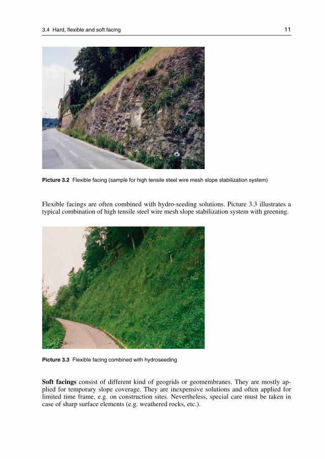
Flexible facing is commonly known as active slope stabilization systems where a steel wiremesh is combined with soil nailing (picture 3.2). Depending on the mesh type, nail andanchor grid must be adapted accordingly.
3.4 Hard, flexible and soft facing 11
Picture 3.2 Flexible facing (sample for high tensile steel wire mesh slope stabilization system)
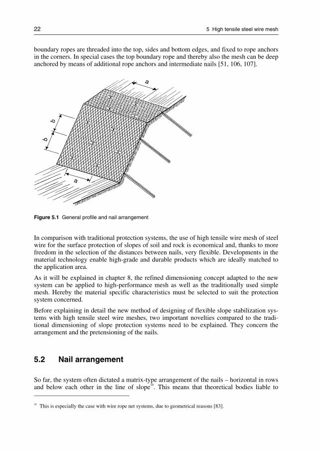
Flexible facings are often combined with hydro-seeding solutions. Picture 3.3 illustrates atypical combination of high tensile steel wire mesh slope stabilization system with greening.
Picture 3.3 Flexible facing combined with hydroseeding
Soft facings consist of different kind of geogrids or geomembranes. They are mostly ap-plied for temporary slope coverage. They are inexpensive solutions and often applied forlimited time frame, e.g. on construction sites. Nevertheless, special care must be taken incase of sharp surface elements (e.g. weathered rocks, etc.).

12 3 Traditional methods using mesh and wire rope nets
Due to limited ultraviolet resistance of such plastic products, aging is a serious problem fora lot of products. Consequently, such soft facings are mostly not recommended for durableand long-term slope stabilization solutions.
Picture 3.4 Soft facing (sample for high tensile geogrid)
The TECCO slope stabilization system is a kind of special flexible facing and therefore, theRUVOLUM dimensioning method as well as this publication focus on flexible facings withhigh tensile steel wire meshes.

4 Traditional dimensioning methods
In the past, various geotechnical calculations and dimensioning concepts were developedand because state of the art for general slope protection engineering7.
For the purpose of dimensioning the surface protection systems of mesh and/or wire ropenets in their interaction with nailing, it is necessary to investigate possible failure mecha-nisms.
On the one hand, the installation of the protective devices must ensure that a layer of soil oralso a layer of weathered and unconsolidated rock of thickness t can be retained with acertain safety against sliding off parallel to the slope on a stable layer as illustrated on fig-ure 4.1.
Figure 4.2 on the other hand shows that local wedge-shaped bodies must be stopped frombreaking out.
Figure 4.1 Sliding off parallel to the slope Figure 4.2 Local wedge-shaped rupture bodies
7 Corresponding (geotechnical) dimensioning concepts are e.g. presented in various publications [47, 75, 109,114].

14 4 Traditional dimensioning methods
4.1 Sliding off parallel to the slope
From considerations of equilibrium concerning a body of width a, length b and thickness t,and taking into account the failure condition of Mohr – Coulomb, the following shear forceS with a stabilizing effect results as far as sliding off parallel to the slope is concerned.
Since the nail heads are fixed against each other, proof of the admissible inner shear resis-tance of the nail S
zul (adm)being greater than the shear resistance S per individual nail required
for a certain safety, is generally sufficient.
Figure 4.3 presents an overview of all forces that are active on the body with a width a, alength b and a thickness of t in order to determine the shear force S that is required for acertain safety level [110].
G Dead weight of the cubic body (G = a · b · t · γ)
γ Unit weight of the soil material
S Shear force, to be absorbed by the nail
t Thickness of the surface layer to be stabilized
c · a · b Cohesion of the cover layer × ground surface of the body liable to break out
T, N Reaction forces from the subsoil
αα Inclination of the slope front
Figure 4.3 All forces active on the body of width a, length b and thickness t to determine the shearforce S required for a certain safety
Based on the overview of all active forces on the body with a width a, a length b and athickness t, the following equation 4.1 explains the calculation of the corresponding shearforce S.
( sin cos tan )[kN]
a b t F c a bS
F F
γ α α ϕ⋅ ⋅ ⋅ ⋅ ⋅ − ⋅ ⋅ ⋅= −
Equation 4.1 Equation of all active forces on the body of width a, length b and thickness t to determinethe shear force S required for a certain safety. F being the safety factor

4.2 Local wedge-shaped bodies liable to break out 15
4.2 Local wedge-shaped bodies liable to break out
As a result of the investigation of “sliding off parallel to the slope”, the nails are now di-mensioned so that the cover layer as a whole can be retained with a certain safety. Furtherinvestigation is then required in the area between the individual nails.
Depending on the slope’s geometry it is possible that wedge-shaped rupture bodies comeloose unless they are covered by mesh or wire rope nets. Such bodies are to be retained andsecured by the use of mesh or wire rope nets as surface protection measures.
The body liable to break out wants to move downwards on a slant. The mesh is held at thetop by nails and if appropriate by boundary ropes, is thus subjected to tension. This is ap-plied on the one hand via friction and on the other over the outward movement of the bodyin question [111].
These interactions are illustrated on the following figure 4.4:
Figure 4.4 Surface stabilization system in combination with soil nailing, local wedge-shaped bodies
The force Z parallel to the slope and with a stabilizing effect is called the net or fasteningforce Z (see also figures 4.5 and 4.6).
It is theoretically the force which is transmitted over the mesh or net in the line of slopeonto the nail, assuming that the entire force exerted by the mesh or net onto the soil or rockwedge is transmitted onto the nail.

16 4 Traditional dimensioning methods
Figure 4.5 Wire mesh with the net force Z active Figure 4.6 Rope net with the net force Z activeon the nail on the nail
The equilibrium conditions are formulated on the basis of the wedge-shaped body in fig-ure 4.7 to determine the net force Z. The failure condition of Mohr – Coulomb is againtaken into account.
Figure 4.7 All forces active on the wedge-shaped body of width a, whereby N and T represent thereaction forces from the subsoil

4.3 Required input quantities 17
The following equation 4.2 results for the net force Z per fastening point by solving theequation system and after the corresponding algebraic conversions.
Hereby the angle ρ is varied to such an extent that Z is the maximum, whereby ρ ≤ arc tan(t/b) is to be the case.
tan ( sin ( ) cos ( ) tan )[kN]
2 ( cos sin tan )
cos ( cos sin tan )
a b b FZ
F
c a b
F
ρ γ α ρ α ρ ϕ
ρ ρ ϕ
ρ ρ ρ ϕ
⋅ ⋅ ⋅ ⋅ ⋅ ⋅ − − − ⋅=
⋅ ⋅ − ⋅
⋅ ⋅−
⋅ ⋅ − ⋅
Equation 4.2 All forces active on the wedge-shaped body of width a, whereby N and T represent thereaction forces from the subsoil
Taking into account a certain safety level F, the wire mesh plus possibly installed bracingropes or the wire rope net, respectively, must be able to transmit the force Z into the nail.
If this is not possible with the selected distance between nails due to the system, the dis-tances between nails must be adapted accordingly.
4.3 Required input quantities
In order to dimension the surface protection system consisting of wire mesh or wire ropenet and nailing, it is necessary, on the one hand to determine the geotechnical characteristicvalues of the surface layer to be protected.
On the other hand, various geometrical figures such as the inclination of the slope, the hori-zontal distance between nails and that in the line of slope, or the layer thickness must bestated [75, 112, 115].
The overview below shows the parameters required for dimensioning:
Geotechnical parameters
Friction angle ϕϕ [°]
Cohesion c [kN/m2]
Unit weight γ [kN/m3]
Geometrical input quantities
Inclination of the slope α [°]
Distance between nails, horizontal a [m]
Distance between nails, line of slope b [m]
Layer thickness t [m]
Safety level Fmod
[–]

18 4 Traditional dimensioning methods
4.4 Proof of the terrain’s resistance against sliding
(deep sliding surfaces)
This investigation concerns the proofs of safety against failure of the terrain, for which thenails are included in the stability calculations with the topographically and geologicallyadapted sliding surfaces, usually as tension elements with a stabilizing effect and in rarercases as shear elements.
These proofs must be established separately and are not directly related to the proofs for theprotection of the surface, except that the nail pattern should correspond as far as possible tothe system related, usual nail distances [1, 56, 71].
Typical failure cases are e.g. curved sliding surfaces (figure 4.8) and straight-lined slidingsurfaces (figure 4.9).
Figure 4.8 Curved sliding surfaces Figure 4.9 Straight-lined sliding surfaces
For further and more detailed information regarding investigations of the global stability,please see chapter 8.8.

5 High tensile steel wire mesh
High tensile steel wire meshes were developed by the end of the last century for the veryfirst time and they are commercially available since the early stage of the new millennium.These meshes are produced with different types of high carbon steel wires, using differentwire diameters and mesh geometries [44, 45, 48].
Today, these high tensile steel wire meshes are widely used for different applications suchas natural hazard protection systems (pictures 5.1 and 5.2) [138], architecture (picture 5.3),intrusion, escape and blast protection, security fences as well as for certain defence applica-tions and against biological hazard threats.
Picture 5.1 Rockfall barrier with high tensile steel wire mesh
Picture 5.2 Avalanche prevention system with high tensile steel wire mesh

20 5 High tensile steel wire mesh
Picture 5.3 Architecture safety application with high tensile steel wire mesh
Picture 5.4 illustrates the high performance load capacity of high tensile steel wires, wherea car is lifted by a single 3.0 mm wire.
Picture 5.4 A high tensile steel wire (1′770 N/mm2) with a diameter of only 3.0 mm is lifting a car8
8 Lifting test with the 3.0 mm high tensile steel wire was conducted by the Swiss Federal Research institute WSLat the Walenstadt rockfall barrier test site in Switzerland on the occasion of the International Geobrugg AnnualMeeting dated June 23rd 2006.

5.1 High tensile wire mesh as a slope stabilization system 21
On the following picture 5.5, a heavy concrete block with the weight of 16′000 kg is liftedby a small mesh panel made from high tensile steel wires with a diameter of 3.0 mm.
Picture 5.5 A concrete block with the weight of 16 metric tons (16′000 kg) is lifted up by a small stripeof a high tensile steel wire mesh with wire diameter of 3.0 mm9
5.1 High tensile wire mesh as a slope stabilization system
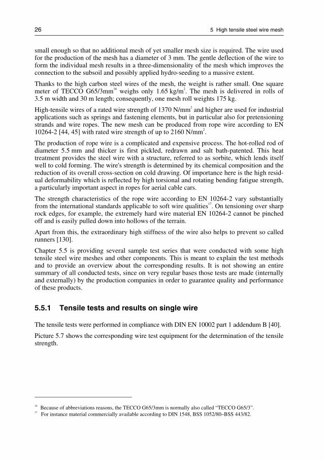
If high tensile wire mesh is used as a surface stabilization system, the slope of soil or rockto be protected is cut as suitable and levelled as possible to the profile (analogous to theapplication of simple conventional mesh as protection systems) and then covered with ahigh tensile steel wire mesh which is secured to soil or rock nails (figure 5.1). Normally,
9 Mesh lifting test with the TECCO G65/3 mm high tensile steel wire mesh was conducted by the Swiss FederalResearch institute WSL at the Walenstadt rockfall barrier test site in Switzerland on the occasion of the Interna-tional Geobrugg Annual Meeting dated June 23rd 2006.
22 5 High tensile steel wire mesh
boundary ropes are threaded into the top, sides and bottom edges, and fixed to rope anchorsin the corners. In special cases the top boundary rope and thereby also the mesh can be deepanchored by means of additional rope anchors and intermediate nails [51, 106, 107].
Figure 5.1 General profile and nail arrangement
In comparison with traditional protection systems, the use of high tensile wire mesh of steelwire for the surface protection of slopes of soil and rock is economical and, thanks to morefreedom in the selection of the distances between nails, very flexible. Developments in thematerial technology enable high-grade and durable products which are ideally matched tothe application area.
As it will be explained in chapter 8, the refined dimensioning concept adapted to the newsystem can be applied to high-performance mesh as well as the traditionally used simplemesh. Hereby the material specific characteristics must be selected to suit the protectionsystem concerned.
Before explaining in detail the new method of designing of flexible slope stabilization sys-tems with high tensile steel wire meshes, two important novelties compared to the tradi-tional dimensioning of slope protection systems need to be explained. They concern thearrangement and the pretensioning of the nails.
5.2 Nail arrangement
So far, the system often dictated a matrix-type arrangement of the nails – horizontal in rowsand below each other in the line of slope10. This means that theoretical bodies liable to
10 This is especially the case with wire rope net systems, due to geometrical reasons [83].

5.3 Pretensioning of the nails 23
break out can be formed between the nails. They extend over the full height of the slopeand are in the maximum as wide as the horizontal distance a between nails. In future, a nailpattern is to be selected on purpose in which the nails in the rows are offset by half a hori-zontal distance between nails (figures 5.1 and 5.2). This means that the maximum possiblebodies liable to break out are limited to a width a and a length of 2 · b [52, 108].
Figure 5.2 Nail head section with spike plate
This nail pattern represents a basic pattern. In the choice of nail positions, the structure ofthe mesh now enables to deviate from this basic pattern within reasonable limits (figures5.1 and 5.3). Local discontinuities in the slope can be counteracted in optimum manner. Iflow points exist, it is recommended to position the nails in those spots so that the mesh isoptimally tensioned by the tightening of the nail [53].
Figure 5.3 Top view of nail head section and spike plate (principle drawing)
5.3 Pretensioning of the nails
The method of designing a flexible slope stabilization system with high tensile steel wiremeshes is providing a new concept of load transfer around the nail head area. This allowssubstantial increased and optimized force transfer from the mesh to the spike plates andfinally into the main nails.

24 5 High tensile steel wire mesh
The nail head area is designed so that it can be pretensioned with the force V (see also pic-ture 5.6). This improves the static effectiveness of the system and limits the deformations inthe area of the slope.
Pretensioning is enabled by special head plates and the high static effectiveness of the hightensile mesh itself. Depending on static requirements, the pretensioning forces to be appliedby controlled tightening of the nut in the nail’s head section amount up to maximum 50 kN(e.g. for the high tensile mesh with the so called TECCO system).
Picture 5.6 Spike plate with high tensile steel wire mesh
Important remark
Only meshes made from high tensile steel wire can be used as above mentioned. Normalsteel wire meshes tend to deform plastically, and those nets are unable to distribute thepretensioning forces and will therefore not be able to transfer the necessary loads11.
5.4 High tensile steel wire mesh
As presented at the beginning of chapter 5, there is a wide use for meshes made from hightensile steel wire. The most well known ones are the so called ROMBO12, DELTAX13 andTECCO meshes.
11 For general geotechnical slope protection applications, it is strongly recommended that such conventional steelwire meshes should only be used with smaller nail grids of max. 1.5 m nail distances [108].
12 ROMBO high tensile steel wire meshes are normally made from 4.0 mm wire. They are especially used forarchitectural, security and industrial safety applications.
13 DELTAX meshes are made from high tensile wires with smaller diameters. The mesh DELTAX G80/2 is alight weight alternative to standard hexagonal steel wire meshes with a diameter of 2.7–3.0 mm [4]. Due to thevery low weight of only 0.65 kg/m2, they are preferred for many applications, especially also in steep terrainwith complicated access.

5.5 Material properties of high tensile wire mesh 25
TECCO is by far the most common used mesh for geotechnical and geological engineeredsolutions. It is typically installed for rockfall protection kits, attenuator and drape systems,avalanche prevention systems as well for debris flow, mud flow and landslide protectionapplications.
For flexible slope stabilization systems, the so called TECCO G65/314 is the most commonused high tensile steel wire mesh. Consequently, this publication will refer often to this typeof steel wire mesh.
The high tensile wire mesh type TECCO G65/3 has a considerable tensile strength of ap-proximately 150 kN/m in longitudinal direction. Substantially higher forces can be ab-sorbed by this mesh in comparison with the wire mesh traditionally available on the market,offering a tensile strength in longitudinal direction of approximately 50 kN/m at compara-ble mesh size and similar wire diameter.
Compared to wire rope nets, the high-tensile wire mesh with their special properties pro-vide a statically virtually equivalent surface protection system which is, however, substan-tially more economical. Figure 5.4 shows the high tensile mesh of type TECCO in a three-dimensional, schematic presentation.
Figure 5.4 Schematic, three-dimensional presentation of high tensile mesh type TECCO
5.5 Material properties of high tensile wire mesh
The new mesh type TECCO G65/3 of high tensile wire features a diamond-shaped individ-ual mesh measuring 83 mm × 143 mm15. They are produced by single twisting of the wirelike for a diagonal mesh. This results in a calibre diameter of 65 mm, which is normally
14 The technical data sheet of TECCO G65/3 is shown on appendix B. (Wire diameter is 3.0 mm, mesh unit open-ing is 65 mm.)
15 Detailed geometry is shown on the technical data sheet of TECCO G65/3 in appendix B.
26 5 High tensile steel wire mesh
small enough so that no additional mesh of yet smaller mesh size is required. The wire usedfor the production of the mesh has a diameter of 3 mm. The gentle deflection of the wire toform the individual mesh results in a three-dimensionality of the mesh which improves theconnection to the subsoil and possibly applied hydro-seeding to a massive extent.
Thanks to the high carbon steel wires of the mesh, the weight is rather small. One squaremeter of TECCO G65/3mm16 weighs only 1.65 kg/m2. The mesh is delivered in rolls of3.5 m width and 30 m length; consequently, one mesh roll weights 175 kg.
High-tensile wires of a rated wire strength of 1370 N/mm2 and higher are used for industrialapplications such as springs and fastening elements, but in particular also for pretensioningstrands and wire ropes. The new mesh can be produced from rope wire according to EN10264-2 [44, 45] with rated wire strength of up to 2160 N/mm2.
The production of rope wire is a complicated and expensive process. The hot-rolled rod ofdiameter 5.5 mm and thicker is first pickled, redrawn and salt bath-patented. This heattreatment provides the steel wire with a structure, referred to as sorbite, which lends itselfwell to cold forming. The wire's strength is determined by its chemical composition and thereduction of its overall cross-section on cold drawing. Of importance here is the high resid-ual deformability which is reflected by high torsional and rotating bending fatigue strength,a particularly important aspect in ropes for aerial cable cars.
The strength characteristics of the rope wire according to EN 10264-2 vary substantiallyfrom the international standards applicable to soft wire qualities17. On tensioning over sharprock edges, for example, the extremely hard wire material EN 10264-2 cannot be pinchedoff and is easily pulled down into hollows of the terrain.
Apart from this, the extraordinary high stiffness of the wire also helps to prevent so calledrunners [130].
Chapter 5.5 is providing several sample test series that were conducted with some hightensile steel wire meshes and other components. This is meant to explain the test methodsand to provide an overview about the corresponding results. It is not showing an entiresummary of all conducted tests, since on very regular bases those tests are made (internallyand externally) by the production companies in order to guarantee quality and performanceof these products.
5.5.1 Tensile tests and results on single wire
The tensile tests were performed in compliance with DIN EN 10002 part 1 addendum B [40].
Picture 5.7 shows the corresponding wire test equipment for the determination of the tensilestrength.
16 Because of abbreviations reasons, the TECCO G65/3mm is normally also called “TECCO G65/3”.17 For instance material commercially available according to DIN 1548, BSS 1052/80–BSS 443/82.

5.5 Material properties of high tensile wire mesh 27
Picture 5.7 Equipment for tests on single wires
The test on a single wire produced the following results18:
Parameters of the wires
Nominal diameter of wire: 3.0 mmNominal strength: 1′770 N/mm2
Measured length: 100 mmSurface treatment: Al-Zn-Coating
The following table 5.1 provides an overview of the tested single wires:
Tensile strength test on single wires
Sample type Sample no. Breaking load, Fm
(N)Tensile strength R
m
(N/mm2)
1 13′150 1′814Single wire withdiameter = 3.0 mm,length = 100 mm 2 12′920 1′770
Average values 13′035 1′792
Table 5.1 Results of tests on single wires
The elongation value A100mm was between 2.0 and 2.5%.
18 Test were co-ordinated and supervised by TÜV Rheinland, LGA Nuremberg, Germany [13, 78, 81].

28 5 High tensile steel wire mesh
It is obvious that the above mentioned two wire tests would make it difficult for detailedstatistical analysis. However, most high tensile steel wire manufacturing sites are checking,testing and reporting all main technical data of supplied wires, (e.g. including tensile, bend-ing, torsion and coating tests). In that sense, all wires used for high tensile steel wiremeshes are carefully tested prior to production in order to ensure quality and technical per-formance.
A wider range of selected TECCO 3.0 mm high tensile wire tests is shown on appendix Gin order to illustrate the steel wire quality control.
5.5.2 Machinery for the mesh tests in longitudinal
and transverse directions
In these test series a new testing installation was used, designed and able to simulate aplane bi-directional tensile load condition of any kind of mesh.
Picture 5.8 shows the overview of the new mesh test equipment.
This new testing installation19 allows testing a wide variety of nets and meshes, because ithas freedom in the number of bracing points of the mesh along the borders and the possibil-ity to adjust the size of the sample.
Picture 5.8 Overview picture of mesh test equipment
19 Test method was developed by Geobrugg AG (Romanshorn, Switzerland) in co-ordination with Rüegger+FlumAG (St. Gallen, Switzerland), University of Cantabria (Santander, Spain) and supervised by TÜV Rheinland(Nuremberg, Germany) [13, 78, 81, 128, 129, 131].

5.5 Material properties of high tensile wire mesh 29
The testing installation consists of a modified main frame with increased width and twonew anvil blocks mounted within. One of them (in blue colour) is fixed to the main frameand the other one sliding (in red colour) is connected to the pulling cables. The mesh isbraced to sliding beams through a set of elements provided with two ring and ball bearings.Six screw bolts that allow the adjustment of the sample width and connect the sliding beamto the lateral fixation support. The bolts on one side were instrumented to register the trans-versal load transferred to the fixation (pictures 5.9 and 5.10).
Pictures 5.9 Lateral fixation system of sliding beams to adjust the width of the test sample. In the leftthe connecting screw bolts that serves as transversal load measurement devices.
In the secondary frame, is installed the hydraulic cylinder with a load measurement cell inthe head of the piston. The secondary frame also serves as a guide of the sliding car, whichtransfers the load applied by the hydraulic cylinder by means of cables to the test sample.
Pictures 5.10 View of the fixed anvil blocks (in blue colour) and the sliding anvil (in red colour) with thepoints of connection of the sample ends

30 5 High tensile steel wire mesh
Details of the device for the measurement of the longitudinal deformation can be seen onthe picture 5.11.
Picture 5.11 Detail of the device for the measurement of the longitudinal deformation
Picture 5.12 provides an overview of the secondary frame with the hydraulic cylinder andthe connections with the sliding car.
Picture 5.12 View of the secondary frame with the hydraulic cylinder and the sliding car

5.5 Material properties of high tensile wire mesh 31
5.5.3 Test setup and results for tensile test in the longitudinaldirection
The main parameters of the tested mesh can be summarized as follows:
Parameter of mesh:
Mesh type: TECCO G65/3 (opening 65 mm; 3.0 mm wires)
Width: 1′079 mm (13 rhombuses × 83 mm = 1′079 mm)
Length: 1′001 mm (7 rhombuses × 143 mm = 1′001 mm)
No. of meshes in the direction of tension: 7
No. of meshes transverse to the direction of tension: 13
The following picture 5.13 shows the experimental setup for the tensile test in the longitu-dinal direction.
Picture 5.13 Experimental setup for tensile tests in the longitudinal direction
Table 5.2 presents the results of the longitudinal tensile tests:
Longitudinal tensile strength tests
Sample type(1079 × 1001 mm)
Sample no. Unitary elongation (mm/m) Breaking load (kN/m)
1 58.9 167.5
2 60.8 165.7
High tensile steelwire mesh, typeTECCO G65/3
3 61.8 167.9
Average values 60.5 167.1
Table 5.2 Results of longitudinal tensile strength tests20
20 All tests are co-ordinated, supervised, documented and reported by TÜV Rheinland, Germany [13, 78, 81, 127].

32 5 High tensile steel wire mesh
Figure 5.5 Results of the tensile tests in longitudinal direction (TECCO G65/3)
Summary of the results of the longitudinal direction tests
− The meshes were loaded until failure.
− They broke at loads between 165.7 kN/m and 168.0 kN/m.
− Rupture deformation was between 58.9 mm/m and 61.8 mm/m.
− The load-deformation curve shows an almost unique, smooth and repeatable behaviourof all test meshes.
5.5.4 Test setup and results for tensile test in the transverse direction
For set up of the tensile test in the transverse direction, the parameters of the mesh were asfollows:
Parameters of mesh:
Mesh type : TECCO G65/3 (opening 65 mm; 3.0 mm wires)
Width : 1′001 mm(7 rhombuses × 143 mm = 1′001 mm)
Length : 581 mm(7 rhombuses × 83 mm = 581 mm)
No. of meshes in the direction of tension: 7
No. of meshes transverse to the direction of tension: 7
Picture 5.14 shows the overview of the experimental setup for the tensile tests in the trans-verse direction.

5.5 Material properties of high tensile wire mesh 33
Picture 5.14 Experimental setup for tensile tests in the transverse direction
The table 5.3 summarizes the test results of the transverse tensile tests and figure 5.6 illus-trates the corresponding results graphically.
Transverse tensile strength tests
Sample type(1079 x 1001 mm)
Sample no. Unitary elongation (mm/m) Breaking load (kN/m)
1 204.6 57.0
2 211.4 59.6
High tensile steel wiremesh, type TECCOG65/3 mm
3 198.5 56.5
Average values 204.8 57.7
Table 5.3 Results of tests of transverse tensile strength test21
21 All tests are co-ordinated, supervised, documented and reported by TÜV Rheinland, Germany [13, 78, 81, 127].

34 5 High tensile steel wire mesh
Figure 5.6 Results of the tensile tests in transverse direction (TECCO G65/3)
Summary of results of the transverse direction test
− The meshes were loaded until failure.
− The meshes broke at loads between 56.5 kN/m and 59.6 kN/m.
− Rupture deformation of the meshes was between 198.5 mm/m and 211.4 mm/m.
− The load-deformation curve shows an almost unique, smooth and repeatable behaviourof all test meshes.
5.6 Corrosion protection
To meet the high demands in respect of durability, the known anti-corrosion process ofaluminium-zinc alloying is used to protect the wire surface. The protective layer forms akind of eutectic alloy. The zinc acts as the cathode towards the steel wire. The admixedaluminium slows down the decomposition process of the zinc layer by a factor22 of atleast 3. The effect of the cathode protection is that local injuries of the protective layercause no corrosion in the particular spot.
This contrary to plastic-coated wires, where local damage to the plastic layer leads to con-centrated corrosion attacks, sometimes additionally combined with under-rusting effectswhich results in even accelerated corrosion activities.
22 Reference to several publications of Prof. Dr. Rolf Nünninghoff and others [2, 91, 92, 93, 94, 95, 96].

5.6 Corrosion protection 35
The aluminium-zinc process for wires has been practised for some time and is used on bothsoft wires for common mesh and fence wires along motorways, but also on high-tensilewires especially in the fishing industry or for vineyards.
The maximum possible deposit of zinc or Al/Zn alloys depends on the wire diameter. Thelayer thicknesses or the mass per square meter are also laid down by European Standard EN10244-2 [44]. Although it is known that the decomposition of zinc layers depends in gen-eral heavily on the locally prevailing conditions, a sufficient life span is achieved with theadvanced technology of Al/Zn protective layer also in a highly corrosive environment.
Important remarks regarding corrosion protection and thickness of coatings:
− The actual thickness of the corrosion protective layer (e.g. zinc coating or zinc alumin-ium coatings) is important for the life span and for the level of corrosion protection.
− However, the quality and especially the purity degree of such coatings may even bemore important since pollution particles and/or impurities can have a negative influenceto the processes of corrosion protection. Such impurities may cause accelerated electro-chemical processes and will influence the appropriate functioning of the sacrificial an-ode corrosion protection of the coatings.
− Consequently, the corrosion protection level can not only be measured by the thicknessand the type of the coating. Its quality and purity are often even more important. There-fore, accelerated weathering tests are an important tool to measure and compare corro-sion protection of different wire and coating types.
5.6.1 Accelerated weathering tests
In order to ensure the sustainability of the high tensile steel wire meshes, various acceler-ated weathering tests were conducted as follows:
SO2Test (SO
2spray test, Kesternich test)
The tests were carried out in accordance with DIN 50018 KFW 2.0 S [10, 42, 63]. Therequired amount of SO2 (2 litre) was made with addition of 11.35 g natrium sulphide(NA2SO3) in 800 ml, with distilled water, concentrated sulphuric acid. 5 test samples weretaken out after 5 and 10 spray cycles for the determination of the corresponding remainingcoating thickness.
Salt spray tests (NaCl spray test)
The tests were made according to DIN 50021 SS23 [3, 10, 43, 63]. 5 test samples were takenout after 100 and 200 hours of spray operation for the determination of the correspondingremaining coating thickness.
Test material
The test material was a high tensile strength steel wire (same as TECCO G65/3 wire) with awire diameter of 3.0 mm. The initial coating thickness (zinc and aluminium zinc coating24)was for both types of wire 300 g/m2. The length of the test samples was 30 cm.
23 DIN 50021 SS is almost equal to ASTM-B117 (USA).24 The used Zn–Al-coating was according to GEOBRUGG Supercoating standard.

36 5 High tensile steel wire mesh
Results of corrosion laboratory tests
The results are shown on the following figures 5.7. It can be summarized that many similartests were carried out on various test institutes worldwide and that all test investigationsshowed that the life time of Zn–Al-coating (supercoating) is at least three times (3×) betterthan standard Zn-coating.
Figure 5.7 Overview of average value results of saltspray test and Kesternich testComparison between Zn-coated and Zn–Al-coated wires; red curve = Zn–Al-coating; blue curve = Zn-coatingLeft: NaCl – spray test (salt spray test)Right: SO2 – spray test (Kesternich test)
5.6.2 Longterm field test for comparison between Zn coatedand Zn-Al coated wires
The cross sections illustrated on pictures 5.15 show a comparison of wires treated with Zn–Al-coating25 and hot-dip galvanization.
The pictures were taken by an electron microscope26 after the wires had been exposed toenvironmental influences for 14 years.
The top pictures show the surface of the zinc-aluminium coating whereas the bottom pic-tures show the surface of a standard zinc coating (hot-dip galvanized).
25 Geobrugg Supercoating type of Zn–Al coated steel wires were used.26 Tests and research done by Bergische Universität Wuppertal (University of Wuppertal), Germany [10, 97, 98]
in co-ordination with the Technical Department of Geobrugg AG.

5.6 Corrosion protection 37
Zn-Al-Coating
Standard Zinc Coating
Pictures 5.15 Comparison between Zn–Al coated wires (top pictures) and standard zinc coated wires(bottom pictures) after 14 years
The picture 5.16 provides a more detailed view of the zinc coating surface. The top level(1) shows a heterogeneous surface with partial complete disintegration and with heavy rustcomponents. Below, there is the second layer (2) which is an intermediate hard zinc layerconsisting of iron and zinc. And at the bottom, there is the actual steel wire (3).
Picture 5.16 Surface of a standard zinc coating (hot-dip galvanized)1) Heterogeneous surface (zinc), partially complete disintegration and/or already with rust formation2) Hard zinc layer (iron/zinc)3) Steel wire (Fe)
The following picture 5.17 shows the details of the zinc aluminium coated wire surface. Onthe top (1), there is a smooth surface with aluminium oxide layer. The main coating (2)illustrates the darker parts of the structure with the aluminium lamellas of the typical eutec-tic structure as a homogeneous coating level with zinc and aluminium. And at the bottom(3), there is again the core with the steel part of the wire.

38 5 High tensile steel wire mesh
Picture 5.17 Surface of a zinc aluminium coated steel wire1) Smooth surface (aluminium oxide layer)2) Homogeneous zinc-aluminium layer3) Steel wire (Fe)
5.6.3 Long-term field study of Zn–Al-coated wires in alkalineenvironment
During the installation process it cannot fully be avoided that the high tensile steel wiremeshes are getting in contact with anchor grout, fresh concrete or part of shotcrete. There-fore, the influence of such interactions were investigated during a long-term field test study[9].
The long-term field study that has been carried out that examined for the first time the cor-rosion resistance of Zn-Al coated wire mesh in an alkaline environment, i.e. in contact withanchor grout.
Unlike non-coated steel wires that do not corrode in fresh concrete with a pH value be-tween 12 and 13, corrosion affects galvanized and Zn-Al coated wires in this medium.However, the CO2 entering the concrete induces a fast reduction of the pH value. The affec-tion of the Zn and Zn/Al alloys is reduced and protective layers are built up around thewires. Once the protective layer is fully established, the behaviour regarding corrosion canhardly be distinguished from atmospheric conditions.
Experiment set-up
Material used: TECCO mesh G65/3
Wire diameter 3.0 mm
Tensile strength 1′770 N/mm²
Zn/Al-Layer (Coating) 200 g/m²
Different Zn–Al coated high tensile steel wire meshes where installed on a test site in Ro-manshorn, Switzerland (see following picture 5.18).
Besides the reference samples, some samples where covered fully or partially with grout.Another sample was splattered with grout, but cleaned with a towel after 30 minutes. Thisprocedure aimed to simulate different kinds of contact between mesh and grout that mayoccur during the installation of such a protection system.

5.6 Corrosion protection 39
In the detail, the following samples were installed (picture 5.18):
A: Reference surface TECCO-mesh “without grout” (fully covered during grout applica-tion)
B: TECCO mesh, grout and galvanized anchor
C: TECCO mesh, splattered with grout
D: TECCO mesh, splattered with grout and cleaned with a towel after 30 minutes
E: Reference area for lab tests and reference values (cut and stored)
F: TECCO mesh covered with anchor/nail grout
Picture 5.18 Test site in Romanshorn (Switzerland)
Removal of the samples
The removal of the samples took place after 2½ years and was documented with pictures(partially shown on pictures 5.19).
Pictures 5.19 Test site after 2.5 years (left) and detail of sample (right)

40 5 High tensile steel wire mesh
Determination of the thickness of zinc aluminium layers
Volumetric method
The thickness of the Al–Zn-layers was determined by the volumetric method according toDIN EN 10244-2. The coating is peeled off chemically by HCl and the volume of the hy-drogen produced by the reaction is determined. The gravimetric method was discarded,because the result has been falsified by the adhesion of grout parts on the wire.
Metallographic analyses
Metallographic analyses have been carried out for the further assessment of the coatings inthe transition area grout/air. The thickness of the layers are given in µm. The conversioninto g/m2 (comparative values to the volumetric analysis) was carried out using the formula10 µm = 71 g/m²27. The values are only conditionally comparable with those of the volumet-ric analysis, because grout and mud falsify the results. This is why grindings were onlyanalyzed for the transition area grout/air.
Test of adhesion and embrittlement
The adhesion of the coatings on the steel core was carried out by a torsion test according toDIN EN 10244-2, where the wire is revolved around its own diameter.
Summary of the test results
The pictures of the grindings from the transition area air/grout do not show any differences(see following pictures 5.20).
Pictures 5.20 Sample pictures for comparisonLeft: Sample that was outside the groutRight: Sample that was inside the grout
Even under the most extreme conditions (1×d), the winding test does not cause any cracksin the Zn-Al layer (pictures 5.21).
27 1 µm = 7.14 g/m²

5.7 Connection of mesh panels 41
Pictures 5.21 Sample pictures of surface of test materials (after winding tests)Left: Sample that was outside the groutRight: Sample that was inside the grout
Conclusions of field study in alkaline environment
It may be stated that after 2½ years of outdoor weathering, no differences between groutfree or grout covered parts of the TECCO mesh can be observed.
According to the present results, it may be concluded that Al–Zn coated wire mesh may bein contact with grout and can be used as shotcrete reinforcement without any impairmentconcerning their life span.
5.7 Connection of mesh panels
5.7.1 Importance of connection elements
One single mesh roll or mesh panel does not really help to stabilize an entire slope. There-fore it is of great importance that the individual mesh panels can be combined together bysimple means in order to ensure the functioning of a uniform membrane structure of theentire mesh area. It is technically very important that this connection is transferring 100%of the load, can be done safe and from an installation point of view, can be applied quickand little time consuming, whenever possible without the need of additional tools and/orhand machines.
5.7.2 Connection clip
The developed connection clip T328 is made from high-tensile steel wire with a minimumtensile strength of 1′770 N/mm2 just like the high tensile steel wire mesh itself.
For the connection clip T3, a wire diameter of 4.0 mm is used. The clip (figure 5.8) is only60 × 21 mm and has two reversed end hooks on the one side of the clamp [54].
28 Drawings are shown on appendix D.

42 5 High tensile steel wire mesh
Figure 5.8 Clip for connection of individual mesh panels
This new connection clip can be fixed without any tool which provides an important advan-tage, especially in steep terrain, where additional tools may cause extra efforts and timeconsuming working steps during the mesh connection processes.
On picture 5.22, the hand installation of the connection clip is illustrated.
Picture 5.22 Hand application process for installation of connection clip
The load tests (shown in the following chapter 5.7.2) proof that these connection clips cantransfer 100% of the necessary load between the individual mesh panels. And this is ofgreat importance if a uniform membrane structure made from different meshes shall bedesigned and applied.
5.7.3 Setup and results of connection element tests
In the development of the connection clip T3 on the calibrated tension test bench of Geo-brugg AG, tension tests at interconnected TECCO G65/3 meshes were executed in thetransversal direction [54, 125].

5.6 Corrosion protection 43
Furthermore, tension tests were also executed by Baremo GmbH on their calibrated tensiontest device in the longitudinal direction.
The following pictures 5.23 show the test arrangement and the conditions before and afterloading.
Picture 5.23 Test arrangement for basic clip tests (BAREMO GmbH, Romanshorn, Switzerland)
Picture 5.24 shows an overview of the test arrangement for the mesh connection elementtests and picture 5.25 provides a detailed view of the mesh connection for the clip test.
Picture 5.24 Overview of test arrangement for clip tests (Geobrugg AG, Romanshorn, Switzerland)

44 5 High tensile steel wire mesh
Picture 5.25 Detail of test arrangement for clip tests
The following pictures 5.26 and 5.27 demonstrate the functioning of the clip connectionduring and after the load tests.
Picture 5.26 Condition right before the collapse of the high tensile steel wire mesh
Conclusion of the tensile and load transfer tests
All the tests have shown that the new connection clip T3, used in every diamond mesh, isable to transfer more load than the TECCO G65/3 for both lateral and longitudinal connec-tion of the mesh.
Correct installation and fixation of the clips and the neighbouring mesh panels are of greatimportance. Chapters 10.7.3 and chapter 10.7.4 explain the appropriate layout of the differ-ent connection options.

5.8 System spike plate 45
Picture 5.27 Condition right after the collapse of the high tensile steel wire mesh
5.8 System spike plate
Beside the high tensile steel wire mesh, the TECCO spike plate is one of the most impor-tant system elements. This special plate has been carefully designed in order to meet thebest possible load and force transmission between soil, mesh, plate and nail.
It is important that the spike plate is installed horizontally (figure 5.9). This allows thecoverage of 16 individual wires of the mesh. If the plate is installed vertically, only 8 indi-vidual wires of the mesh are contacted and significant less force transmission can takeplace. For further information accordingly, please see also chapter 10.7.
Figure 5.9 Spike plates need to be oriented horizontally; long side must be horizontal. (horizontalinstallation covers 16 steel wires, vertical installation covers only 8 steel wires)
As a result of various evaluation, material and design tests, the final shape and form of theTECCO system spike plate was found. The following pictures 5.28 and 5.29 show part ofthe corresponding material component tests.

46 5 High tensile steel wire mesh
Picture 5.28 Material tests of system spike plate
Picture 5.29 Material tests of system spike plate
It is very decisive that the bending resistance of the system spike plate is high enough inaccordance with the TECCO wire mesh (figure 5.10).

5.9 Comparison with traditional steel wire meshes 47
stiff enoughtoo soft
Figure 5.10 Importance of correct stiffness of system spike plate
Important conclusion
The TECCO slope stabilization system must consist of the official system spike plate.Otherwise, load transmission and system performance will not be possible in accordancewith the system’s design.
The usage of other plates (even if they look similar) may have serious consequences re-garding safety and security of the entire slope stabilization system. Consequently, onlythe original system spike plate shall be used for the TECCO system.
5.9 Comparison with traditional steel wire meshes
The previous chapters described the parameters and characteristics of the high tensile steelwire meshes. In order to demonstrate the significant differences to traditional steel meshes,several comparison tests were conducted. Some of the strongest commercially availablewire meshes were chosen in order to provide a fair comparison and show the unique per-formance and load transformation capacities of high tensile steel wire meshes.
5.9.1 Comparison test with heavy chainlink mesh made fromtraditional steel wire
Table 5.4 shows the material parameters regarding the comparison test between a hightensile steel wire mesh and a heavy chainlink mesh made from traditional steel wire.
The following pictures 5.28 and 5.29 show the test setup for the comparison test29. The testequipment as well as the test conduction was made in accordance to the tests methods de-scribed before (chapter 5.5.2). Reference width of test panels was 1.0 m.
29 Test were co-ordinated, supervised, documented and reported by TÜV Rheinland, Germany [80, 126].

48 5 High tensile steel wire mesh
Wire types Mesh with high tensile steelwire mesh
Mesh with traditional tensile steelwire mesh
Wire diameter 3.0 mm 4.6 mm
Tensile strength Min. 1′770 N/mm2 550–650 N/mm2
(according to manufacturer)
Mesh types TECCO G65/3 mm Chain-link mesh 50 × 50 mm
Weight 1.65 kg/m2 5.60 kg/m2
Mesh unit width 83 mm 80.5 mm
Mesh unit length 143 mm 73.5 mm
Picture of meshsamples
Table 5.4 Parameter and geometries of different mesh types
Picture 5.30 Test setup for the comparison tests with mesh made from high tensile wires (1′770 N/mm2)
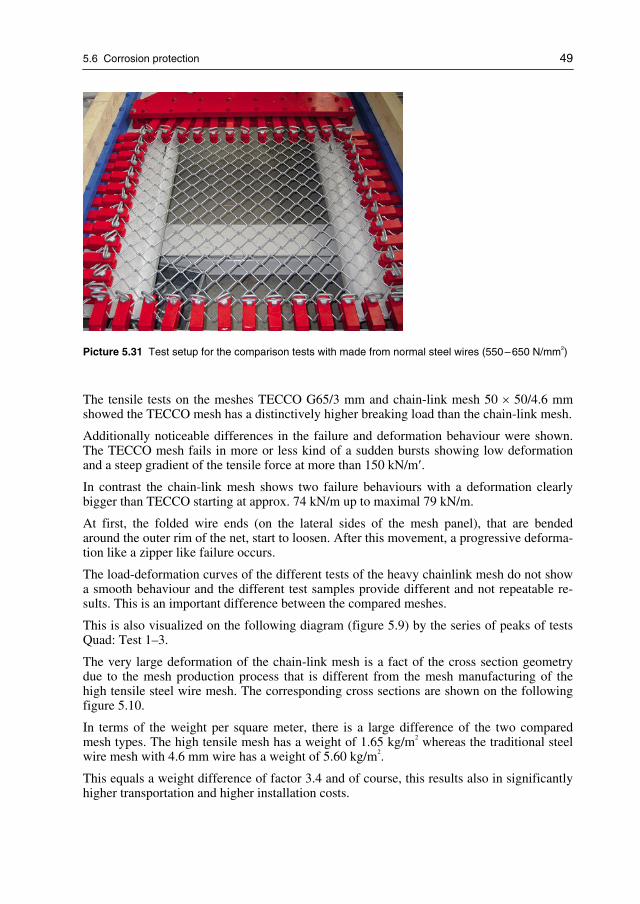
5.6 Corrosion protection 49
Picture 5.31 Test setup for the comparison tests with made from normal steel wires (550–650 N/mm2)
The tensile tests on the meshes TECCO G65/3 mm and chain-link mesh 50 × 50/4.6 mmshowed the TECCO mesh has a distinctively higher breaking load than the chain-link mesh.
Additionally noticeable differences in the failure and deformation behaviour were shown.The TECCO mesh fails in more or less kind of a sudden bursts showing low deformationand a steep gradient of the tensile force at more than 150 kN/m′.
In contrast the chain-link mesh shows two failure behaviours with a deformation clearlybigger than TECCO starting at approx. 74 kN/m up to maximal 79 kN/m.
At first, the folded wire ends (on the lateral sides of the mesh panel), that are bendedaround the outer rim of the net, start to loosen. After this movement, a progressive deforma-tion like a zipper like failure occurs.
The load-deformation curves of the different tests of the heavy chainlink mesh do not showa smooth behaviour and the different test samples provide different and not repeatable re-sults. This is an important difference between the compared meshes.
This is also visualized on the following diagram (figure 5.9) by the series of peaks of testsQuad: Test 1–3.
The very large deformation of the chain-link mesh is a fact of the cross section geometrydue to the mesh production process that is different from the mesh manufacturing of thehigh tensile steel wire mesh. The corresponding cross sections are shown on the followingfigure 5.10.
In terms of the weight per square meter, there is a large difference of the two comparedmesh types. The high tensile mesh has a weight of 1.65 kg/m2 whereas the traditional steelwire mesh with 4.6 mm wire has a weight of 5.60 kg/m2.
This equals a weight difference of factor 3.4 and of course, this results also in significantlyhigher transportation and higher installation costs.

50 5 High tensile steel wire mesh
Figure 5.11 Comparison of results of the tensile tests in longitudinal direction of the steel wire meshTECCO G 65/3 mm and the chain-link mesh net 50 × 50/4.6 mm
Figure 5.12 Different cross sections of high tensile steel wire mesh (TECCO, on top) and traditionalsteel wire mesh (chainlink, at bottom)
These large deformations of traditional steel wire meshes can result in serious deformationand load transfer problems when applied for slope stabilization purposes.
The following picture 5.30 illustrates such deformation problems with steel wire meshesmade from normal tensile wires (e.g. below 1′000 N/mm2).
Because of the weight difference, the available mesh panel sizes are different:
− High tensile steel wire mesh panel: 3.5 m × 30 m = 105 m2 per roll
− Traditional steel wire mesh panels: 2.75 m × 6 m = 16.5 m2 per panel
Consequently, the traditional mesh type panel is around six times smaller and requiresaround eight times more panel overlapping than the new mesh made from high tensilestrength steel wire.

5.6 Corrosion protection 51
Picture 5.32 Slope stabilization system made with traditional steel wire meshes (chain-link, 50 ×50 mm, 4.6 mm wire diameter). Nail distance was chosen too large and consequently, large deforma-tions of the wire mesh occurred in short time.
These facts are also illustrated on figure 5.11 where the horizontal and vertical lines indi-cate the borders of the individual mesh panels (traditional steel wire meshes) and the yellowsection indicates the size of one single panel of high tensile steel wire mesh (TECCOG65/3). For comparison reasons, the TECCO mesh (yellow) is illustrated in a horizontalway.
eff. area only2.25 m x 5.5 m= 12.4 m2
= only 75 %
Figure 5.13 Yellow section = area of one roll of high tensile steel wire meshOrange section = area of one roll of traditional steel wire mesh (low tensile wire mesh)Green section = orange area reduced due to required overlapping of mesh panels
As a conclusion of this comparison, TECCO G65/3 mesh requires much less mesh overlap-ping of individual panels. This means that less mesh area is totally needed and that theinstallation time (and costs) can be significantly reduced due to the fact that much lessmesh connections have to be made.

52 5 High tensile steel wire mesh
5.9.2 Comparison test with reinforced hexagonal mesh madefrom traditional steel wire
Table 5.5 shows the material parameters regarding the comparison test between a hightensile steel wire mesh and a reinforced hexagonal wire mesh.
Wire types Mesh with high tensile steelwire mesh
Mesh with reinforced hexagonalmesh
Wire diameter 3.0 mm 3.0 mm
Tensile strength Min. 1′770 N/mm2 350–550 N/mm2
(according to manufacturer)
Mesh types TECCO G65 / 3mm Hexagonal mesh with reinforcementof 8 mm steel wire ropes
Breaking load ofwire rope
– 40.3 kN(according to manufacturer)
Mesh unit width 83 mm 80 mm (measured)
Mesh unit length 143 mm 100 mm (measured)
Picture of meshsamples
Table 5.5 Parameter and geometries of different mesh types
The following pictures 5.31 and 5.32 show the test setup for the comparison test30.
The corresponding test equipment as well as the test conduction was made in accordance tothe tests methods described before (chapter 5.5.2). Reference width of test panels was1.0 m.
30 Tests were co-ordinated, supervised, documented and reported by TÜV Rheinland, Germany [79].

5.6 Corrosion protection 53
Picture 5.33 Test setup for the comparison tests with mesh made from high tensile wires(1′770 N/mm2)
Picture 5.34 Test setup for the comparison tests with the reinforced hexagonal made from normal steelwires (approx. 350–550 N/mm2); reinforcement by 8.0 mm steel wire rope (centrally arranged)
The tensile tests on the meshes TECCO G65/3 mm and hexagonal wire mesh 80 ×100/3 mm with wire rope 8 mm longitudinal showed that the TECCO mesh has a distinc-tively higher breaking load than the hexagonal mesh together with the rope.
Additionally noticeable differences in the failure and deformation behaviour were shown.The TECCO mesh fails more or less in a kind of sudden bursts showing low deformationand a steep gradient of the tensile force at more than 160 kN.

54 5 High tensile steel wire mesh
During the first tensile tests using the hexagonal wire mesh with a wire rope longitudi-nally arranged, the lateral drillings of the hexagonal wire mesh open after each other.Thereby, the maximum transmissible load amounts to 36.0 kN with a deformation of119.3 mm.
To avoid any opening of lateral drillings during the tests 2 and 3, the drillings are fixed withwire rope clips. The behaviour is thus improved compared with the real application.
The corresponding breaking loads amount to 44.8–51.2 kN with a deformation of 77.7–83.1 mm as shown on the load-deformation diagram shown on figure 5.12.
The wire rope transfers noteworthy loads up to approx. 47 kN after nearly all wire meshesfailed (after a deformation of about 140 mm). The elements hexagonal wire mesh and wirerope do not act at the same time but after each other.
The load-deformation curves of the different tests of the reinforced hexagonal steel wiremesh do not show a smooth behaviour and the different test samples provide different andnot repeatable results. This is an important difference between the compared meshes.
Figure 5.14 Comparison of results of the tensile tests in longitudinal direction of the steel wire meshTECCO G65/3 mm and the hexagonal wire mesh 80 × 100/3 mm with reinforcement of the wire rope8 mm
Picture 5.33 shows the rupture of the hexagonal wire mesh before the rupture of thesteel wire rope. This particular status demonstrates the fact that the two different materials,rope and hexagonal mesh, have different material properties and do not really functiontogether.

5.6 Corrosion protection 55
Picture 5.35 The steel wire rope does not significantly support the hexagonal wire mesh because thewire rope can only transfer load if it is fully straight. As long as the steel wire rope is curved (e.g.“S-form”), it is unable to transmit tensile forces in order to support the loads that are applied to thehexagonal steel wire mesh

56 5 High tensile steel wire mesh

6 Tangential force transmission, mesh to nail
Several types of rupture mechanisms are considered in the investigation of local instabili-ties. Hereby it is assumed that the investigated failure bodies want to move downwardsrelative to the mesh. By this relative movement and due to the fact that the mesh is heldlocally by means of spike plates, upwardsdirected, slope-parallel forces are initiated in themesh itself. If these forces are integrated over a surface of a
red× 2b, the force Z results31.
The mesh must be able to selectively transmit this force Z with a certain safety onto the naillocated immediately above the failure mechanism under investigation.
The test setup was developed with the supervision of TÜV Rheinland, LGA Nürnberg,Germany and in co-ordination with the company Rüegger+Flum AG, St. Gallen, Switzer-land [13, 78, 127]. This collaboration was of great importance since concept, tests andanalysis of the results must be fully independent and shall be conducted completely exter-nally. Consequently, it could be ensured that all test results are fully externally and thirdparty approved and certified.
With the aid of this setup it has been possible to investigate the force deformation behav-iour of various mesh types and to formulate the corresponding maximum admissible forcesin the mesh. Hereby the mesh was locally held by spike plates and subjected to a load intangential direction by means of a rope tensioning arrangement.
6.1 Test setup for tangential force transmission, mesh to nail
The test setup consists in the main of a metal container which is rigidly secured to twostationary U-profiles, and of a square metal frame into which the mesh to be investigated isclamped.
The metal container is filled with soil to the extent that the surface of the layer of soil isflush with the top edge of the metal container. A nail is arranged in the centre of the metalcontainer. The mesh to be investigated is held by a spike plate which is pressed onto thesubstrate by means of a nut.
The rope tensioning arrangement pulls at two brackets fastened to the frame. The meshclamped into the frame is centrally held by means of a spike plate. The forces impartedover the brackets into the frame and thereby into the mesh are locally transmitted onto thenail.
Figure 6.1 provides the principle overview of the setup for the tangential force transmissiontest. The force Z indicates location and direction of pulling ropes of the hydraulic tensiontest machinery.
31 Determination of ared
is explained in chapter 8.3.

58 6 Tangential force transmission, mesh to nail
Figure 6.1 Schematic presentation of tangential force transmission test (principle drawing). Force Z
shows location and direction of pulling ropes of tension test unit
On picture 6.1, the test unit for the determination of the tangential force transmission test isshown.
Picture 6.1 Test unit for determination of tangential force transmission test

6.2 Test results for tangential force transmission, mesh to nail 59
6.2 Test results for tangential force transmission,
mesh to nail
The figure 6.2 shows the force deformation behaviour in respect of tangential tensile testsfor
(I): a hightensile mesh with a tensile strength of the individual wires of min. 1′770 N/mm2
(or a tensile strength of the mesh in longitudinal direction of approx. 150 kN/m),
(II): a traditional wire mesh with a tensile strength of the individual wires of approx.500 N/mm2 (or a tensile strength of the mesh in longitudinal direction of approx. 50 kN/m)and
(III): for a geogrid of PET with a tensile strength in longitudinal direction of approx.40 kN/m, in the form of three families of curves.
The applied spike plate was round and of a diameter of D = 220 mm. The test setup in ques-tion is explained in the following paragraph.
Figure 6.2 demonstrates also that by using high-tensile mesh compared to the common wiremesh with a mesh tensile strength in longitudinal direction of approx. 50 kN/m, the tangen-tially directed force which can be transmitted selectively onto the nail is significantlyhigher. Various tests with geogrids of PET (polyester) revealed that these products cantransmit forces onto a nail only to a very limited degree.
0
5
10
15
20
25
30
35
40
0 20 40 60 80 100 120 140 160 180
Tensionforce[kN]
II
III
I
Deformation[mm]
Figure 6.2 Force-deformation behaviour in the tangential tension testI High-tensile wire mesh with tensile strength of the mesh in longitudinal direction of approx.
150 kN/mII Common wire mesh with tensile strength of the mesh in longitudinal direction of approx. 50 kN/mIII Geogrid of PET with tensile strength of the mesh in longitudinal direction of approx. 40 kN/m

60 6 Tangential force transmission, mesh to nail
The selected bearing resistance of a high-tensile wire mesh of a tensile strength in longitu-dinal direction of approx. 150 kN/m against selective, slope-parallel tensile force amountsto approx. 25 kN when a round spike plate of a diameter of D = 220 mm (figure 6.2) isused.
Tests with a wire mesh of a tensile strength in longitudinal direction of approx. 50 kN/mhave shown a load at rupture of approx. 8–12 kN. The corresponding, prudently selectedbearing resistance against selective, slope-parallel tensile force amounts in this case to Z
R=
6–8 kN when a round spike plate of D = 220 mm is used.
For a grid fabric of polyester (PET) of a tensile strength in longitudinal direction of approx.40 kN/m in combination with a round spike plate of D = 220 mm, loads at rupture ofapprox. 2–4 kN were measured. A prudently selected bearing resistance of Z
R= 1–2 kN
results from this.
The force-deformation behaviour depends on the shape and size of the applied spike plate.
Average test results with the TECCO spike plate in accordance to the test setup shown onpicture 6.1 are showing a bearing resistance of 48.3 kN32.
These material characteristics of the TECCO G65/3 mesh is very important for flexiblefacings with static function regarding flexible slope stabilization systems.
32 LGA Nürnberg Test Report BGT 0230101 and BPI 0400046/1, Nuremberg, Germany [13, 78].

7 Force transmission nail to meshin nail direction
Apart from the bearing resistance of the mesh to be concentrated, slope-parallel tensilestrains Z
R, the bearing resistance of the mesh to pressure strains in nail direction D
Rmust be
determined.
Supervised by TÜV Rheinland and in co-ordination with the company Rüegger+Flum AG,this test arrangement was developed [13, 78, 127] what ensured that concept, tests andanalysis could be conducted completely externally, approved by third party and certifiedaccordingly.
The corresponding test setup is presented in figure 7.1 and on picture 7.1.
The objective of this test series was to obtain a force-deformation relation for verticalstrains for the different types of mesh, on the basis of which the system-dependent force D
R
is to be defined.
Apart from the determination of V, it was possible to investigate the deformation behaviourin the immediate area of the spike plate under certain strains.
Figure 7.1 Schematic overview of test setup

62 7 Force transmission nail to mesh in nail direction
Picture 7.1 Test setup for puncturing test with TECCO spike plate
7.1 Test setup for force transmission nail to mesh
in nail direction
The test setup consists of a round steel container which is completely filled with soil mate-rial. This filled steel container is framed by four squarely arranged HEA profiles whichserve to fasten the mesh to be tested.
A GEWI nail is located in the centre. By means of a hydraulic press the spike plate and alsothe mesh are pressed onto and into the soil. The shape of the resulting compressed body isschematically outlined in section A-A.
7.2 Test results for force transmission nail to mesh
in nail direction
Figure 7.2 shows the families of curves resulting from different pressure tests for a high-tensile wire mesh of a tensile strength of the individual wires of approx. 1′770 N/mm2, for atraditionally common wire mesh of a tensile strength of the individual wires of approx.500 N/mm2 and for a geogrid of PET.
For comparison purposes, the behaviour of the test ground without the involvement of amesh is shown in curve (4). A round spike plate of steel of D = 220 mm was used.
If the hydraulic press presses the spike plate directly onto the ground without involvementof a wire mesh, a corresponding hollow results at a certain force V
oG(figure 7.3).
The force VoG
is transmitted directly into the substrate over the spike plate. If an analogoustest is carried out, but with the involvement of a wire mesh, the vertical force can be furtherincreased by a certain dimension ΔV to V
mGuntil the same deformations occur. The differ-

7.2 Test results for force transmission nail to mesh in nail direction 63
0
50
100
150
200
250
0 20 40 60 80 100 120 140 160 180 200 220 240
I
II
III
IV
D
Pressureforce
[kN]I
II
IIIIII
IV
D
Deformation
[mm]
Figure 7.2 Pressure force – deformation relations of three different products as a result of puncturetests in nail direction using a round spike plate of diameter D = 220mm;I High-tensile wire mesh with tensile strength of the mesh in longitudinal direction of approx.
150 kN/mII Common wire mesh with tensile strength of the mesh in longitudinal direction of approx. 50 kN/mIII Geogrid of PET with tensile strength of the mesh in longitudinal direction of approx. 40 kN/mIV Subsoil without contribution from a mesh cover
ence ΔV = VmG
– VoG
is laterally transmitted over the mesh via pressure and friction forcesinto the solid ground. Hereby the amount of V
oG, approximately, flows again directly over
the spike plate into the substrate.
Figure 7.3 Pressing into the ground of the spike plate, without/with mesh
To determine the bearing resistance of the mesh against pressure strains in nail direction DR,
the corresponding differential forces are taken into account. The force DR, therefore, de-
pends more or less on the wire mesh itself only, and no longer on the ground.

64 7 Force transmission nail to mesh in nail direction
Accordingly, the following applies:
VmG
= VoG
+ ΔV
DR
= ΔV
Equations 7.1
When comparing the three different force-deformation behaviours of the individual meshtypes in figure 7.2 it becomes evident that a clearly higher pretensioning force is possible ifhigh-tensile mesh are used (the round spike plate of D = 220 mm was used in those cases).
The families of curves in figure 7.2 apply to a certain test ground (in the case on hand:natural gravel 0–32 mm). Differences may occur in the force-deformation behaviour of theindividual mesh if other test grounds are used.
The bearing resistance of the mesh against shearing-off in nail direction at the upslope edgeof the spike plate can be assumed to be half of the bearing resistance of the mesh againstpressure strains in nail direction.
Additional tests series were conducted with TÜV Rheinland in order to test and certify thepuncture values for the combination of TECCO spike plate and the high tensile steel wiremesh33.
Soil used
For this test purpose a natural coarse aggregate (gravel) with grain size 0/16 mm was used.The tank was filled with the prepared material in three layers of gravel and compacted witha portable vibrant compactor up to a dry density of 22 kN/m3.
Tests without high tensile steel wire mesh
The test series initially served to determine the pure bearing effect of the spike plate systemcompared to the substrate used. The test substrate was loaded until significant deformation(shear failure) occurred.
Test substrate failed at loads between 208.78 kN and 228.52 kN. The deformation meas-ured was between 154.1 mm and 187.8 mm.
Picture 7.2 shows the setup of the puncture test with the spike plate only, whereas picture7.3 provides an overview of the arrangement for the puncture test with the spike plate in-cluding the high tensile steel wire mesh.
The results of these tests are shown on figure 7.4.
33 TÜV Rheinland Test Report BPI 0400046/1 (Dr. Peter Brändlein), LGA Nürnberg, Germany [78].

7.2 Test results for force transmission nail to mesh in nail direction 65
Picture 7.2 Puncture test with spike plate only (without any mesh)
Tests with high tensile steel wire mesh
The high tensile steel wire mesh type TECCO G65/3 mm was used for these tests includingthe system spike plate.
The length and width of the test frame were 2′000 mm.
The first part of the curves corresponds to the compression of the high tensile steel wiremesh. The second steep section corresponds to the elastic deformation of the soil founda-
Picture 7.3 Puncture test with spike plate (including high tensile steel wire mesh)

66 7 Force transmission nail to mesh in nail direction
tion and then the rest of the curves corresponds to the movement of the soil along the fail-ure surfaces up to the breaking of the high tensile steel wire mesh.
The failure occurred at loads between 516 kN and 533 kN with deformations between164.6 mm and 164.7 mm (see also figure 7.4).
Figure 7.4 Punching test compacted gravel and TECCO mesh including system spike plate.
Figure 7.4 and the corresponding puncturing test can be summarized as follows:
The puncturing test without the high tensile steel wire mesh yielded bearing capacitiesbetween 208 kN and 228 kN. In the experiments including the TECCO meshes, the failurewas reached at loads between 516 kN and 533 kN.
The difference of the results in a compressive load capacity of the meshes in the directionof the nail (without the influence of the test substrate) was between 287.6 kN and 324.9 kNwith an average value of 306 kN.

8 New designing method for flexibleslope stabilization systems
The new designing method for flexible slope stabilization system RUVOLUM34 is based onthe concepts used so far. In principle, it is applicable to all common surface protectionsystems on the market, which provide for nailing in combination with a mesh or a wire ropenet (or a mixture of the two), as a surface protection system which permits any distancebetween nails in both horizontal and vertical direction. It is pointed out especially that newdimensioning method RUVOLUM is not restricted to the dimensioning of protection sys-tems using high tensile steel wire mesh exclusively.
Contrary to the traditional concept and as a major novelty, not only wedge-shaped one-body sliding mechanisms but also two-body sliding mechanisms are investigated whenconsidering local instabilities. Hereby the geometry is selected with simplifications so thata more or less shell-shaped failure body is simulated as far as the sliding mass is concerned.
Moreover, it is assumed for simplification’s sake that, as a reaction, a tensile force parallelto the slope is active on the nail immediately above the local failure mechanism to be inves-tigated, and a tensile force in nail direction is active on the nail underneath this mechanism.
The axial tensile forces in the nails can be activated by pretensioning. The application ofthe pretensioning forces leads to the following advantages:
− The active application of the pretensioning forces onto the nails means that the spikeplates and thereby the mesh are pressed onto the subsoil. These outer pressure forcesacting on the surface of the steep terrain permit to mobilize additional friction forcesalong the sliding surfaces under examination. This has a positive effect above all on thestability.
− If no active pretensioning force is applied to the nail and if a local failure body wants tobreak out, the mesh must first be deformed to be able to mobilize the forces required toretain the shape liable to break out. Slight pressing-in of the spike plate applies the pre-tensioning forces to the mesh, i.e. the forces necessary to prevent local instabilities arealready mobilized. As a result, failure bodies can hardly come loose any more from thelayer to be protected.
The new dimensioning method comprises two investigations:
Investigation of superficial instabilities parallel to the slope
The cover layer which is liable to slide off a more stable substrate must be retained as awhole by the nailing. Each nail must be able to hold a body of width a, length b and thick-ness t with a certain safety. Figure 8.1 illustrates the corresponding superficial instabilitiesparallel to the slope.
34 The dimensioning method for flexible slope stabilization system with high tensile steel wire mesh is often alsocalled “RUVOLUM concept” or “RUVOLUM method” [108, 109, 144].

68 8 New designing method for flexible slope stabilization systems
Figure 8.1 Superficial instabilities parallel to the slope
Investigation of local instabilities
If the nailing is dimensioned and laid out so that sliding-off of the cover layer as a wholecan be prevented, further investigation is required to clarify whether or not instabilities mayoccur locally, i.e. between the individual nails (figure 8.2). These possible local failurebodies are to be retained with a certain safety by the application of the surface protectionsystem consisting of nailing and mesh cover.
Figure 8.2 Local instabilities between individual nails

8.1 Investigation of superficial instabilities parallel to the slope 69
8.1 Investigation of superficial instabilities parallel to the slope
The investigation of superficial instabilities parallel to a slope examines a cubic body ofwidth a, length b and layer thickness t which threatens to slide off the firm subsoil. Allforces considered and acting on the sliding body are marked in Fig. 8.3.
Hereby it is assumed that no hydrostatic excess pressure and no flow pressure is effectiveon the sliding body. The force G represents the dead weight of the cubic body. The termc ⋅ A describes the retaining influence of the cohesion along the investigated sliding surface,inclined at the angle α to the horizontal plane. By means of c ⋅ A it is also possible to con-sider a.o. an existing denticulation (interlocking) effect between the layer of soil to be pro-tected and the stable substrate, or within the layer of loose rock itself. Force V is a forcewith a stabilizing effect in the direction of the nail which prestresses the mesh against thenail head. By tightening the nut, the spike plate and thereby the mesh is firmly pressed ontoor slightly into the ground, respectively. V is inclined in relation to the horizontal plane bythe angle Ψ. Variable S represents the shear force which is to be absorbed by the nail andtransferred into the stable subsoil. Marked for completeness’ sake are the reaction forces Nand T from the subsoil which act in vertical and tangential direction to the sliding surface.
Figure 8.3 All forces acting on the cubic body
From considerations of equilibrium concerning the cubic body shown in figure 8.3 andtaking into account the failure condition of Mohr-Coulomb, the general equation 8.1 can beformulated for the stabilizing shear force S in function of the geometrical and geotechnicalparameters as well as of the pretensioning force V and the model uncertainty correctionfactor γmod as follows:
S [kN] = 1/γmod · {γmod · G · sin α – V · γmod · cos (Ψ + α) – c · A – [G · cos α + V
· sin (Ψ + α)] · tan ϕ}
Equation 8.1
G = dead weight of sliding body
S = shear force, to be absorbed by the nail
V = pretensioning force
c * A = cohesion of the cover layer * ground surfaceof the body liable to break out,whereby A = a * b
T, N reaction forces from the subsoil
α = inclination of the slope front and slidingsurface, respectively, from horizontal
Ψ = inclination of the nail relative to the horizontalplane
φ = effective friction angle of the cover layer
γmod = model uncertainty correction value

70 8 New designing method for flexible slope stabilization systems
The RUVOLUM dimensioning method is based on the concept with partial safeties pro-claimed in EUROCODE 7 [47].
The characteristic values of friction angle ϕk, cohesion c
kand volume weight γ
kare to be
reduced or multiplied, respectively, by/with the corresponding partial safety correctionvalues γϕ, γc
and γγ (whereby the friction angle ϕkis reduced via the tangent).
Resulting from this are the dimensioning values of the geotechnical parameters ϕd, c
dand γ
d.
Additionally, the stabilizing force V as an external influence must be multiplied by a so-called load factor. From this results the dimensioning value of the force V
dI/II. The modeluncertainty correction factor γmod takes geometrical and model uncertainties into account.
8.2 Stability proofs in the investigation of superficial failures
parallel to the slope
The following three proofs of stability must be established in the investigation of superfi-cial failures parallel to the slope:
− Proof of the nail against sliding-off a superficial layer parallel to the slope
− Proof of the mesh against puncturing
− Proof of the nail to combined forces
8.2.1 Proof of the nail against sliding-off a superficial layer parallelto the slope
In the proof of the nail against sliding-off of a superficial layer parallel to the slope it mustbe guaranteed that the cubic body of width a, length b and thickness t does not slide off theinvestigated sliding surface which is inclined by the angle α in relation to the horizontalplane.
The mathematically required shear force Sd
at dimensioning level, determined according toequation 8.2, must be compared with the bearing resistance S
Rof the nail in respect of pure
shear strain, whereby the resistance correction value γSR
for shearing off of the nail must beconsidered.
Proof of bearing safety is to be established as follows:
Sd≤ S
R/γ
SR
Equation 8.2
The following table 8.1 shows a compilation of the quantities for the proof against sliding-off parallel to the slope:

8.2 Stability proofs in the investigation of superficial failures parallel to the slope 71
Sd
[kN] Dimensioning value of the shear strain under consideration of the dimen-sioning values of the geotechnical parameters and of the external, stabilizingforce V
dI at dimensioning level, whereby the following applies:
Vd I = V · γ
dI
(Vd I acts favourably on force S
d, consequently γ
d1 = 0.80 is generally put).
SR
[kN] Bearing resistance of the nail to shear strain, whereby the following applies:
SR= τ
y· A with τ
y= f
y/ 3 = yielding point under shear strain
fy= yielding point under tensile strain
A = statically effective cross-section of the nail.
γSR
[–] Resistance correction value.
Based on EUROCODE 7, γSR= 1.50 is generally put.
Table 8.1 Proof of the nail against sliding-off parallel to the slope
8.2.2 Proof of the mesh against puncturing
In the proof of the mesh against puncturing it must be investigated whether or not the meshis able to absorb the force V applied in nail direction, and transfer it into the stable subsoil.
Hereby the dimensioning value of the externally applied force V is compared with the bear-ing resistance of the mesh to pressure strain in nail direction, whereby the resistance correc-tion value for puncturing is taken into account.
Proof of bearing safety must be established as follows:
VdII≤ D
R/γ
DR
Equation 8.3
The following table 8.2 shows a compilation of the quantities for the proof against punctur-ing of the mesh due to pretensioning force:
VdII [kN] Dimensioning value of the external force V with which the surface stabiliza-
tion system is prestressed against the nails.
The following applies:
Vd II = V · γVII with γVII = 1.50 (as leading influence).
DR
[kN] Bearing resistance of the mesh against pressure strain in nail direction; to bedetermined by tests developed specifically for the purpose.
γDR
[–] Resistance correction value,
(generally γDR
= 1.50 is put)
Table 8.2 Proof against puncture of the mesh due to pretensioning force

72 8 New designing method for flexible slope stabilization systems
8.2.3 Proof of the nail to combined strain
The nail is subjected to tensile strains by the effectively applied pretensioning force. Addi-tionally, it must prevent a global sliding-off, parallel to the slope, of the layer to be pro-tected.
With the proof of the nail’s bearing safety it must be investigated whether or not the appliednail can withstand these combined strains.
The following proof of bearing safety is established35 as follows:
([VdII /(TR
/γVR
)]2 + [Sd/(S
R/γ
SR)]2)0.5 ≤ 1.0
Equation 8.4
The before mentioned variables are explained in table 8.3 as follows:
VdII [kN] Dimensioning value of the external force V with which the surface stabiliza-
tion system is prestressed against the nails.
The following applies: VdII= V · γVII
γVII = 1.50.
TR
[kN] Bearing resistance of the nail to pure tensile strain, whereby the followingapplies:
TR= f
y· A
fy= yielding point under tensile strain
A = statically effective nail cross-section.
γVR
[–] Resistance correction value.
Based on EUROCODE 7, is generally put on γVR= 1.50.
Sd
[kN] Dimensioning value of the shear strain under consideration of the dimen-sioning values of the geotechnical parameters and of the external, stabilizingforce Vd1 at dimensioning level.
The following applies: Vd1 = V · γ
d1
(Vd1 acts favourable on force Sd, consequently γ
d1 = 0.80 is generally put).
SR
[kN] Bearing resistance of nail to shear strain, whereby the following applies:
SR= τ
y· A
τy= f
y/ 3
τy= yielding point under shear strain,
fy= yielding point under tensile strain
A = statically effective cross-section of nail.
γSR
[–] Resistance correction value.
Based on EUROCODE 7, γSR= 1.50 is generally put.
Table 8.3 Proof of the bearing safety of the nail (combined strains)
35 Based on the Swiss SIA 261 Standard [119].
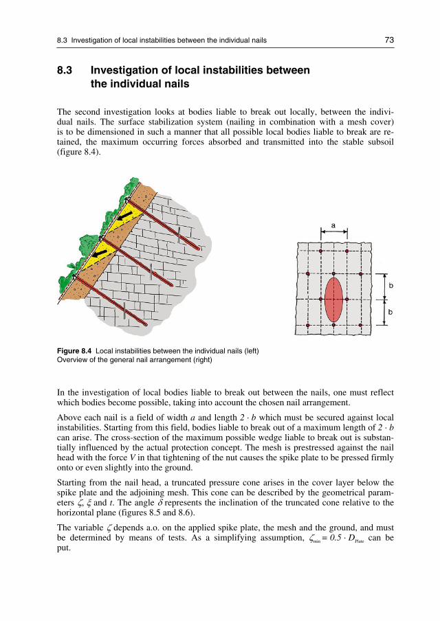
8.3 Investigation of local instabilities between the individual nails 73
8.3 Investigation of local instabilities between
the individual nails
The second investigation looks at bodies liable to break out locally, between the indivi-dual nails. The surface stabilization system (nailing in combination with a mesh cover)is to be dimensioned in such a manner that all possible local bodies liable to break are re-tained, the maximum occurring forces absorbed and transmitted into the stable subsoil(figure 8.4).
Figure 8.4 Local instabilities between the individual nails (left)Overview of the general nail arrangement (right)
In the investigation of local bodies liable to break out between the nails, one must reflectwhich bodies become possible, taking into account the chosen nail arrangement.
Above each nail is a field of width a and length 2 · b which must be secured against localinstabilities. Starting from this field, bodies liable to break out of a maximum length of 2 · bcan arise. The cross-section of the maximum possible wedge liable to break out is substan-tially influenced by the actual protection concept. The mesh is prestressed against the nailhead with the force V in that tightening of the nut causes the spike plate to be pressed firmlyonto or even slightly into the ground.
Starting from the nail head, a truncated pressure cone arises in the cover layer below thespike plate and the adjoining mesh. This cone can be described by the geometrical param-eters ζ, ξ and t. The angle δ represents the inclination of the truncated cone relative to thehorizontal plane (figures 8.5 and 8.6).
The variable ζ depends a.o. on the applied spike plate, the mesh and the ground, and mustbe determined by means of tests. As a simplifying assumption, ζmin = 0.5 · DPlate can beput.

74 8 New designing method for flexible slope stabilization systems
Figure 8.5 Truncated pressure cone: ground plan
Figure 8.6 Truncated pressure cone: general section
The dimensioning model assumes that the pressure cones are completely outside the bodyto be investigated. This means that the cross-section of the maximum possible body liableto break out is trapezoidal and features at the top a width of a – 2 · ζ and at the bottom awidth of a – 2 · ξ = η. For simplification, the trapezoidal cross-section can be transformedto a rectangle of equal area of the width ared = a – t/tan δ – 2 · ζ and thickness t (figure8.7).

8.3 Investigation of local instabilities between the individual nails 75
The body liable to break out and subject of the investigation features a width of ared and amaximum length of 2 · b. The thickness of the body in figure 8.7 amounts to t.
Figure 8.7 Horizontal cross-section of the maximum possible body (liable to break out) of the thickness t
For the proofs of bearing safety in the investigation of local instabilities according to thedimensioning method described in this chapter, it is mandatory to vary the thickness of thebodies to be investigated over the entire interval [0; t] and in this manner to determine thedecisive fault mechanism.
Hereby it must be noted that the variable ared depends directly on the thickness of the inves-tigated body liable to break out and accordingly also varies on variation of the layer thick-ness from 0 to t. If the layer thickness is not varied between 0 and t, this can lead to a sub-stantial underestimation of the effectively occurring forces, particularly if t is selectedgreater than 1/2�
1/3 of the distance between nails in the line of slope. In the interest ofsimplification, only the case thickness of the layer equals t is dealt with in the explanationshereafter.
It must be pointed out that the geometry of the bodies to be investigated and selected in themodel should approximately simulate the saucer-shaped fault contours which occur in real-ity. By the trapezoidal cross-section the actually curved cross-section is described as anapproximation.
For the proofs of bearing safety in the investigation of local instabilities, one must differen-tiate between two failure mechanisms A and B: mechanism A represents a single-bodysliding mechanism whose sliding surface, starting from the bottom nail, runs in a straightline to the top nail under the angle β in relation to the horizontal plane. Failure mechanismB is a two-body sliding mechanism. Hereby the top body I of trapezoidal cross-sectionpresses on the wedge-shaped bottom body II.
Figures 8.8 and 8.9 illustrate these two possible failure mechanism with the accordinglyacting forces.

76 8 New designing method for flexible slope stabilization systems
8.3.1 Failure mechanism A
In the investigation of local instabilities with the aid of failure mechanism A, we look at awedge-shaped body of width ared which threatens to slide off a plane which is inclined inrelation to the horizontal plane by the angle β. All considered forces which are active on thesliding body are marked in figure 8.8. Hereby it is assumed, in analogy to the investigationof superficial slope-parallel instabilities, that no excess hydrostatic pressure and no flowpressure acts on the sliding body (this applies also to fault mechanism B). Force G repre-sents the dead weight of the body breaking out. The cohesion along the sliding surface istaken into account with the term c · A, whereby A = L · ared applies. With c · A it is in turnpossible to describe an existing interlocking effect.
Also active on the body liable to break out, furthermore, are the external forces P and Zwith a stabilizing effect. It is assumed that the investigated body liable to break out andwanting to move relatively downwards, is partly retained via friction by the mesh pressedonto the surface. If these friction forces are integrated over the surface 2b · a
red, the resulting
reaction is the slope-parallel upwards-directed force Z in the mesh, which is to be selec-tively transmitted by the mesh to the upper nail. The force P is assumed to be inclined inrelation to the horizontal plane by the angle Ψ and is introduced as a general force requiredfrom the equilibrium considerations and having a stabilizing effect. For completeness’ sake,the reaction forces N and T from the subsoil, acting in vertical or tangential direction inrelation to the sliding surface, are marked also.
Figure 8.8 Failure mechanism A = one-body sliding mechanism
The relation presented in equation 8.5 results from equilibrium considerations and takinginto account the failure condition of Mohr-Coulomb as well as the model uncertainty cor-rection factor γmod.

8.3 Investigation of local instabilities between the individual nails 77
The maximum force P is to be determined by variation of the inclination of sliding surface β.
⋅ ⋅ − ⋅ − ⋅ ⋅ − − − ⋅ − ⋅=
⋅ + + + ⋅
mod mod
mod
[ sin cos tan ] [ cos ( ) sin ( ) tan ][kN]
cos ( ) sin ( ) tan
G Z c AP
γ β β ϕ γ α β α β ϕ
γ β ψ β ψ ϕ
Equation 8.5
8.3.2 Failure mechanism B
Failure mechanism B is characterized by two bodies liable to break out: The upper, trape-zoidal body I presses over the contact force X onto the lower, wedge-shaped body II.
The width of the two bodies amounts to ared. The forces GI and GII represent the weights ofthe individual sliding bodies and c · AI and c · AII, respectively, the forces due to cohesionalong the investigated sliding surfaces of the individual sliding bodies, whereby AI = L
I· ared
and AII = LII · ared apply. NI and TI, and NII and TII, respectively, in turn stand for the reactionforces from the subsoil.
Analogously to the preceding paragraph, variable Z denotes the slope-parallel force in themesh, to be selectively transmitted on the upper nail. The force P is assumed to be inclinedin relation to the horizontal plane by the angle Ψ and is again introduced as a general re-taining force required from the equilibrium considerations.
For the equilibrium equations, the forces Z and P act on the lower wedge-shaped body II.
On overview of this failure mechanism is shown on the following figure 8.9.
Figure 8.9 Failure mechanism B = two-body sliding mechanism (possible friction forces along thecontact surface of the two bodies I and II are neglected.)

78 8 New designing method for flexible slope stabilization systems
The contact force X results from the equilibrium equations at the upper body I, wherebythe condition of Mohr-Coulomb and the model uncertainty correction factor γmod are takeninto account. To determine the force P, the equilibrium conditions are formulated onbody II. Hereby the contact force X from equation 8.6 and the slope-parallel force Z areentered.
X [kN] = 1/γmod · {GI · (γmod · sin α – cos α · tan ϕ ) – c · AI}
Equation 8.6
⋅ ⋅ − ⋅ + − ⋅ ⋅ − − − ⋅ − ⋅=
⋅ + + + ⋅
mod mod
mod
II II[ sin cos tan ] ( ) [ cos ( ) sin ( ) tan ][kN]
cos ( ) sin ( ) tan
G X Z c AP
γ β β ϕ γ α β α β ϕ
γ β ψ β ψ ϕ
Equation 8.7
The decisive case is to be found by comparing the maximum force P from failure mecha-nism A with that from mechanism B.
8.4 Proofs of bearing safety in the investigation
of local failure mechanisms
The following proofs of bearing safety must be established in the investigation of localinstabilities:
− Shearing-off of the mesh at the upslope edge of the spike plate at the lower nail
− Selective passing-on of the slope-parallel force Z from the mesh onto the upper nail
8.4.1 Shearing-off of the mesh at the upslope edge of the spikeplate at lower nail
In the investigation of local instabilities it must be ensured that a local body of a maximumlength of 2 ⋅ b cannot break out from the securing superficial layer. For this purpose, thenecessary retaining force P
dfrom the equilibrium conditions has been determined in para-
graph 8.3. If a body is about to slide off, it must be possible for this force Pd
to be taken upin the area of the bottom nail by the mesh and accordingly also by the spike plate and thenail (see also figure 8.10 accordingly).

8.4 Proofs of bearing safety in the investigation of local failure mechanisms 79
Figure 8.10 Shear stress on the mesh at the upslope edge of the spike plate at the lower nail
In the proof concerning shearing of the mesh at the upslope edge of the spike plate at thelower nail, it must be investigated whether the applied mesh is able to take up the outwardsacting force component P
dor is sheared off at the upslope edge of the spike plate. Proof of
bearing safety is to be established as follows:
Pd≤ P
R/γ
PR
Equation 8.8
The following table 8.4 shows a compilation of the quantities for the proof against shear-ing-off of the mesh at the upslope edge of the spike plate at the lower nail:
Pd
[kN] Dimensioning value of the maximum shear stress on the mesh at the up-slope edge of the spike plate on the lower nail
PR
[kN] Bearing resistance of the mesh against shearing off in nail direction, to bedetermined by means of the test developed specifically for the purpose
γPR
[–] Resistance correction value
(γPR= 1.50 is generally put)
Table 8.4 Quantities for proof against shearing-off of the mesh at the upslope edge of the spike plate atthe lower nail
8.4.2 Selective transmitting of the slope-parallel force Z
from the mesh to upper nail
The slope-parallel force Z has been introduced for the equilibrium considerations in para-graph 8.3. This force Z in the mesh must be transmitted selectively over the spike plate ontothe upper nail (figure 8.11).

80 8 New designing method for flexible slope stabilization systems
Proof of the bearing safety concerning selective transmitting of the slope-parallel force Zfrom the mesh onto the upper nail must be established as follows:
Zd≤ Z
R/γ
ZR
Equation 8.9
Figure 8.11 Slope-parallel force taken into account in the equilibrium consideration
The following table 8.5 shows a compilation of the quantities for the proof of the selectivetransmission of the slope-parallel force Z from the mesh onto the upper nail:
Zd
[kN] Slope-parallel force taken into account in the equilibrium equations = dimen-sioning value of the stress in slope-parallel direction
ZR
[kN] Bearing resistance of the mesh against selective, slope-parallel tensilestress; to be determined by tests developed specifically for the purpose
γZR
[–] Resistance correction value.
γZR= 1.50 is generally put.
Table 8.5 Quantities for proof of selective transmission of the slope-parallel force Z from the mesh ontothe upper nail
8.5 Parameters to be determined empirically
In the equilibrium considerations in paragraphs 8.1 and 8.3, the pretensioning force V, theretaining force P and the net force Z have been introduced as external forces.
The question now arises how high these forces may be selected in the maximum so thatthey can still be absorbed by the used mesh, the applied spike plate and the nails, takinginto account appropriate safeties.

8.6 Load case “earthquake” 81
The bearing resistance of mesh to pressure strain in nail direction and the bearing resistanceof mesh against selective, slope-parallel tensile strains have been determined with the aid ofvarious test series.
The corresponding test setup as well as the results and analysis were discussed in the chap-ters 6 and 7.
For general assumptions, V = 30 kN for soil and V = 50 kN for weathered rock faces asstandard values based on experiences are recommended.
8.6 Load case “earthquake”
Depending on the importance of the structure and the seismological situation, possibleadditional effects from earthquakes must be investigated when dimensioning slope stabili-zation systems. Generally this takes place using the substitute force procedure.
Here, accelerations acting on a fracture body are converted through the factor36ε
hand fac-
tor37ε
vto additional forces in the horizontal and vertical direction. These additional forces
must be appropriately taken into account in the equilibrium considerations. With steeperslopes, in general in solid rock, special investigations are necessary, e.g. tilting and slidingindividual blocks.
Shown on figure 8.12 are the additions in the formulas resulting from the earthquake loadcase. The corresponding individual proofs remain the same as previously described.
Figure 8.12 Components of acceleration due to earthquake
8.6.1 Investigation of instabilities close to the surfaceand parallel to the slope
The formula for the variable S previously described in equation 8.1 is extended in equation8.10 with the additional forces as a result of the parameters ε
hund ε
v, factors of the horizon-
tal and vertical acceleration as the result of an earthquake. Here the variable S representsthe shear force to be taken up by the nail and transferred to the firm bedrock (figure 8.13).
36ε
his the horizontal acceleration due to earthquake activities and forces. The unit is [m/s2].
37ε
vis the vertical acceleration due to earthquake activities and forces. The unit is [m/s2].

82 8 New designing method for flexible slope stabilization systems
Figure 8.13 Forces applied to a cubic body with the earthquake load case
mod
[kN] (1 ) sin cos cos( )
[ sin ( ) (1 ) cos sin ] tan
v h
v h
S G G V
V G G c A
ε α ε α ψ α
ψ α ε α ε α ϕ
γ
= + ⋅ ⋅ + ⋅ ⋅ − ⋅ +
⋅ + + + ⋅ − ⋅ ⋅ ⋅ + ⋅−
Equation 8.10
8.6.2 Investigation of local instability between the nails
Again, for the proofs of bearing safety in the context of the investigation of local instabili-ties one must differentiate between two failure mechanisms A and B:
− Failure mechanism A represents a one-body sliding mechanism in which the slidingsurface, starting from the bottom nail and extending in a straight line to the upper nail,runs under the angle β to the horizontal plane.
− Failure mechanism B is a two-body sliding mechanism. Hereby the upper body I oftrapezoidal cross-section presses onto the wedge-shaped lower body II. Figures 8.8 and8.9 show these two possible failure mechanisms with the correspondingly active generalforces.
Failure mechanism A
The additional force components as a result of earthquake are introduced in the equilibriumconsideration previously described with equation 8.5 (see equation 8.11). Here the variablesP and Z represent the external stabilizing forces.
The inclination β of the slip surface must in turn be varied in order to determine the maxi-mum force P (figures 8.14).

8.6 Load case “earthquake” 83
Figures 8.14 Forces applied with failure mechanism A including the earthquake load case
ε β ε β α β ϕε β ε β α β
γ
ϕψ β ψ β
γ
mod
mod
[(1 ) cos sin sin ( )] tan(1 ) sin cos cos ( )
[kN]tan
cos ( ) sin ( )
v h cv h
G G Z c AG G Z
P
+ ⋅ ⋅ − ⋅ ⋅ − ⋅ − ⋅ + ⋅+ ⋅ ⋅ + ⋅ ⋅ − ⋅ − −
=
+ + + ⋅
Equation 8.11
Failure mechanism B
The additional force components as a result of earthquakes are likewise introduced withfracture mechanism B. For this the contact force X of equation 8.6 resulting from the equi-librium considerations at the upper body it must be adjusted as represented in equation8.12.
The extended calculation of the necessary restraining force P is shown in equation 8.13.
Figure 8.15 provides an overview about the forces that are applied with failure mechanismB including the earthquake load case.
By analogy with before, the decisive case must also be determined with the maximum forceP from mechanism A and B:
1 I
I I ,I
mod
[kN] (1 ) sin cos
[(1 ) cos sin ] tan
v h
v h c
X G G
G G c A
ε α ε α
ε α ε α ϕ
γ
= + ⋅ ⋅ + ⋅ ⋅
+ ⋅ ⋅ − ⋅ ⋅ ⋅ + ⋅−
Equation 8.12 Contact force X

84 8 New designing method for flexible slope stabilization systems
Figure 8.15 Forces applied with failure mechanism B including the earthquake load case
II II IIII II
mod
mod
[(1 ) cos sin sin ( )] tan(1 ) sin cos cos ( )
[kN]tan
cos ( ) sin ( )
v hv h
G G Z c AG G Z Z
P
ε β ε β α β ϕε β ε β α β
γ
ϕψ β ψ β
γ
+ ⋅ ⋅ − ⋅ ⋅ − ⋅ − ⋅ + ⋅+ ⋅ ⋅ + ⋅ ⋅ + ⋅ − − ⋅
=
+ + + ⋅
Equation 8.13 Retaining force P
8.7 Load case “streaming parallel to the slope”
Described below is the influence of streaming pressure as a result of precipitation water,respectively inflowing ground or slope water in loose rock slopes in the equilibrium con-siderations.
In principle the two types of inflow with precipitation water (from the outside on to theslope) and slope water (from the inside) can be differentiated as shown in figure 8.16:
− Streaming parallel to the slope in case of intensive rain
− Streaming parallel to the slope due to slope water (e.g. waterbearing interbeds, clefts,etc.)
With both cases it is assumed that a streaming parallel to the slope occurs after the satura-tion of the material.

8.7 Load case “streaming parallel to the slope” 85
Figure 8.16 Streaming parallel to the slope in case of intensive rain (left) and slope water, e.g. water-bearing interbeds, clefts, etc. (right)
8.7.1 Investigation of instabilities close to the surfaceand parallel to the slope
The additional force Fs
represents the resulting streaming force parallel to the slope and iscalculated from the sum of the unit weight of the water γ
w, the hydraulic gradient i = sin α
and the volume of the fracture body. Force G represents the dead weight of the cubic body.The term c ⋅ A describes the remaining influence of the cohesion along the investigatedsliding surface which is inclined by the angle α in relation to the horizontal plane. Withc ⋅ A it is basically also possible to take into account an existing interlocking effect betweenthe superficial layer itself. Force V is the force with a stabilizing effect in the direction ofthe nail which pretensions the mesh against the slope surface; by tightening the nut, thespike plate and thereby the mesh is firmly pressed onto the ground. The force V is inclinedin relation to the horizontal plane by the angle ψ. When calculating according to equation8.14, buoyancy is taken into account with the own weight G of the cubic body. Figure 8.17provides a corresponding overview of the applied forces to a cubic body including thestreaming load case. The individual proofs remain the same as stated in previous chapters.
The general shear force S formula, previously represented in equation 8.2 is extended bythe force F
s.
mod
[ sin ( ) cos ] tan[kN] sin cos ( ) s
V G c AS G V F
ψ α α ϕα ψ α
γ
⋅ + + ⋅ ⋅ + ⋅= ⋅ − ⋅ + + −
Equation 8.14 Shear force S

86 8 New designing method for flexible slope stabilization systems
Figure 8.17 Forces applied to a cubic body including the streaming load caseF
s= γ
w⋅ i ⋅ a ⋅ b ⋅ t = γ
w⋅ sin α ⋅ a ⋅ b ⋅ t
8.7.2 Investigation of local instability between the nails
Equal to the chapter 8.6.2, the two relevant failure mechanisms A and B must be analyzedfor the investigation of local instabilities between the nails.
Failure mechanism A
Figure 8.18 presents the applied forces with the failure mechanism A including the stream-ing load case.
Figure 8.18 Forces applied with the failure mechanism including the streaming load case

8.7 Load case “streaming parallel to the slope” 87
The equation for calculating stabilizing force P is enlarged by the force components Fs. The
maximum force P is determined by varying the gradient β of the slip face. The uplift istaken into account with the calculation of the own weight G.
mod
mod
[ cos sin ( )] sin ( )] tancos ( ) sin cos ( )
[kN]tan
cos ( ) sin ( )
s cs
G Z F c AF G Z a
P
β α β α β ϕα β β β
γ
ϕψ β ψ β
γ
⋅ − ⋅ − + ⋅ − ⋅ + ⋅⋅ − + ⋅ − ⋅ − −
=
+ + + ⋅
Equation 8.15 Restraining force P
Failure mechanism B
According to the equilibrium consideration, at the upper body 1 the contact force X of equa-tion 8.6 is extended by the force F
S,I. Represented in equation 8.17 is the extended calcula-
tion of the restraining force P. The own weight G is thereby reduced by the uplift compo-nents (figure 8.19).
The maximum force P from the two fracture mechanisms A and B is determining for theproofs.
Figure 8.19 Forces applied with the break mechanism including the streaming load case
I ,I,I I
mod
cos tan[kN] sin c
s
G c AX F G
α ϕα
γ
⋅ ⋅ + ⋅= + ⋅ −
Equation 8.16 Contact force X

88 8 New designing method for flexible slope stabilization systems
II , ,IIII ,II
mod
mod
[ cos sin ( ) sin ( ) sin ( )] tansin cos ( ) cos ( ) cos ( )
[kN]tan
cos ( ) sin ( )
s II cs
G Z X F c AG X F Z
P
β α β α β α β ϕβ α β α β α β
γ
ψ β ψ βγ
⋅ − ⋅ − + ⋅ − + ⋅ − ⋅ + ⋅⋅ + ⋅ − + ⋅ − − ⋅ − −
=
+ + + ⋅
Equation 8.17 Restraining force P
8.8 Investigation of the global slope stability
Slopes in both soil and solid rock sometimes feature deep-seated sliding surfaces reachingdeep below the slope surface to be protected, which means that a global stability problemexists as well (figure 8.20) [56, 75].
Figure 8.20 Left: Slope of soilRight: Slope of solid rock
The method of flexible slope stabilization system with high tensile steel wire mesh (e.g. theTECCO mesh) is in principle a solution for the stabilization of surface layers. Dimension-ing on the basis of the RUVOLUM method is primarily for layer thicknesses of 1.0 tomaximum 2.0 m.
Therefore, the following important questions must be asked:
− What measures should be taken if deeper sliding surfaces exist as well and need to bestabilized?
− Can the high tensile steel wire mesh slope protection system be applied with reasonablechances of success?
− Can the high tensile steel wire mesh slope protection system be combined with a sub-surface stabilization?
Answer:
This is possible in principle if the nailing and anchoring are matched to the deep-seatedsliding surfaces.

8.8 Investigation of the global slope stability 89
The nails and/or slack anchors (without active pretension) stabilized in mortar over theirfull length must be suitably dimensioned as far as their size/thickness (outer and inner ab-sorption of forces) and length are concerned in order to meet the static requirements of thesubsurface stabilization.
Dimensioning of the nailing and proofs of bearing safety are normally based on classicalstability calculations with circular (BISHOP, FELLENIUS [1, 71]) or combined, i.e. arbi-trarily curved sliding surfaces (JANBU, MORGENSTERN-PRICE, SARMA-HOEK,NONVEILER [1, 71]) which must be adapted to the prevailing geological circumstances.These methods are also used for dimensioning purposes in normal ground or rock nailingoperations. The stabilization must provide a specified minimum safety Fmin in each case(figure 8.21).
The stability of slopes is traditionally estimated using 2D limit equilibrium methods. How-ever these methods have several disadvantages and may neglect some important factors.Due to the rapid development of computing efficiency, several numerical methods are gain-ing increasing popularity in slope stability engineering.
Finite Element Method and Finite Difference Method are very often used for that purpose[18, 19, 21]. The factor of safety for slope may be computed by reducing shear strength ofrock or soil in stages until the slope fails. This method is called shear strength reductiontechnique. However the majority of engineers still prefer using limit equilibrium methodsmainly due to its simplicity, tradition of application and relatively low price of availablecodes.
Figure 8.21 Failure mechanism and stabilization method for deep sliding problems
The method of dimensioning via proofs of the global stability eventually provides theminimum required nailing:
− Nail type (thickness, properties, etc.)
− Distance between nails
− Nail length

90 8 New designing method for flexible slope stabilization systems
Hereby it must be possible to dissipate the nail forces to the substrate on both sides ofthe sliding surface (external bearing safety). Here outwards support is also provided bythe pretensioning of the TECCO system applied in the particular case to the slope surface(table 8.6).
Figure 8.22 illustrates the load distribution over the entire nail length.
Figure 8.22 Load distribution over the nail length
Investigation for global stability
For the investigation of the overall stability, the nails are generally introduced as tension elements.By checking the internal bearing resistances (steel cross-sections and yield point under tensile loadof the nails) and the external bearing resistances (friction forces that can be mobilized, pretensionforces V or maximum head force Dmax that can be mobilized), the terrain’s resistance against sliding ηand the utilization factor 1/f of the existing shear and system resistances are determined.
The tensile resistance available at the intersection between sliding surface and nail is limited by:
1. the internal bearing resistance of the nail Zi
2. the external bearing resistance behind the sliding surface: ZAH = τ2 ⋅ l23. the external bearing resistance ahead of the sliding surface plus the pretensioning force V of the
system or the maximum head force that can be mobilized in case of a failure of the systemagainst puncturing Dmax:
ZAV = τ1 ⋅ l1 + V respectively ZAVmax = τ1 ⋅ l1 + Dmax
whereby the smallest of the values Zi, ZAH and ZAV or ZAVmax is decisive.
Table 8.6 Investigation for global stability

8.8 Investigation of the global slope stability 91
It remains to be investigated, then, whether or not this nailing is compatible with the stabi-lization of the surface layer by means of the TECCO slope stabilization system and whetheror not all proofs can be established for it according to the RUVOLUM method (figure8.23).
By this it is guaranteed that the surface layer of delimited thickness is also adequately pro-tected.
Figure 8.23 Analysis of surface layer slope stabilization investigation
Hereby one often considers only reduced shear strength parameters in the proofs for thissurface layer in order to cover the long-term influences of weathering, loosening, etc. Inparticular, the cohesion c = 0 kN m–2 is put as a rule.
Once the proofs according to the RUVOLUM concept are established with the nailing tomeet the global requirements, nothing needs to be altered any more. If the proofs are notmet (distance between nails for the high tensile steel wire mesh excessive) or if the nails aretoo weak to oppose any sliding parallel to the surface, an adaptation must be made, e.g:
− Reduction of the distance between nails (nail grid)
− Strengthening of the nails (bigger diameter)
− Additional (shorter) nails
Conclusion
The flexible high tensile steel wire mesh slope stabilization system (e.g. TECCO system)designed according to the RUVOLUM method can be combined with a subsurface stabili-zation required for the stabilization of the deeper-seated sliding surfaces.
Apart from the proof as per the RUVOLUM method, classical stability calculations aremade with curved sliding surfaces as proofs of bearing safety. The nailing is optimized onthe basis of both proofs.
The application of the high tensile steel wire mesh slope stabilization system depends pri-marily on the properties of the soil, structure and geometry of ground layers, the slope gra-dient and the prevailing hillside water situation.

92 8 New designing method for flexible slope stabilization systems
8.9 Greening and revegetation
In steep slopes featuring fine-grained, non-cohesive loose rock or severely weathered rockthere is a danger of erosion. Such fine material can be washed through the high tensile steelwire mesh and flushed away underneath it. Hereby channels and hollows may be formedunder the mesh.
Emerging hillside, layer or fissure water must generally be captured and drained. Perma-nent water outflows will always lead to problems and must be coped with before the slopestabilization measure is started, since corrective action is hardly possible afterwards. Par-ticular care must also be taken that no larger quantities of surface water from above flowover the slopes. If appropriate, drain channels must be provided above the edge of the slopeso that the water is drained to the side in a controlled manner.
What remains is the rainwater falling directly onto the protected slope. In case of a highintensity and long duration of the rain, this can also lead to erosion problems. The impact ofthe rain drops and the draining water may lead to soil movements, flushing-away and gen-eral erosion. The problem can be coped with by means of a full-surface vegetation face.The roots stabilize the surface layer and a substantial quantity of water is stored in the vege-tation layer before it starts to flow off.
However, it takes time for an effective vegetation to form and for stable subsoil circum-stances to result also in the small sphere. No vegetation can develop in a slope subject tomovements and erosion. Immediate spraying of erosion-resistant vegetation material andseeding are not always possible directly after laying of the meshes (vegetation period). It isoften necessary, therefore, to provide an erosion protection together with the mesh so thaterosion and washing-out are prevented for the time being and optimal prerequisitesachieved for successful greening later on.
Regrettably it is usually not possible to achieve the goal with the known erosion protectionmats of natural fibres (e.g. jute, choir) because the often irregular surfaces prevent an unin-terrupted ground contact of the mats. The mats in question are normally too tight for spray-ing-through of vegetation material and seeds. The results are undesirable and in the longrun critical bare patches which expose the free surfaces to erosion again as soon as the matshave rotted away.
What was sought, therefore, was a flexible mat of a three-dimensional open structure whichprovides a comparatively good protection against erosion despite relatively large openings.The mat must also be suitable as an adhesion and stabilization layer for the vegetation foras long as the latter is unable to perform this function. Of importance is also that the mat isoptically inconspicuous, i.e. adapted in its colour to the substrate.
After various suitability tests with different products, with dry and wet greening also inextreme locations exposed to the south, a 3-dimensional mat of a loop structure, a so-calledrandom-laid nonwoven fabric of polypropylene was eventually found, which meets thepartly opposing requirements of erosion protection and vegetation face in optimum manner.The technical data compiled on the following page apply to this erosion protection mat,developed especially for use in combination with the TECCO stabilization system andavailable under the trade name of TECMAT (picture 8.1).

8.9 Greening and revegetation 93
Picture 8.1 TECMAT Erosion control mat
Technical data of TECMAT
Raw material: polypropylene
Type of mat: irregular, three dimensional loop structure with punctiform bondings
Thickness: approx. 18 mm
Areal weight: 600 g/m2
Opening width: approx. 5–15 mm
Colour: khaki grey or black
Picture 8.2 shows a typical application of the erosion control mat TECMAT in combinationwith a high tensile steel wire mesh.

94 8 New designing method for flexible slope stabilization systems
Picture 8.2 Erosion control mat combined with high tensile steel mesh
8.10 External examination and inspection
of the new designing method
The new method of the designing of flexible slope stabilization systems with high tensilesteel wire meshes, (also called the “RUVOLUM” dimensioning method), was developed inco-ordination with the company Rüegger+Flum AG, St. Gallen, Switzerland in the contextof the development of high tensile steel wire mesh.
The entire concept of the RUVOLUM dimensioning method for flexible slope stabilizationsystems for wire meshes and nails was also inspected by Prof. Dr.-Ing. L. Wichter, Univer-sity of Cottbus, Faculty for Rock and Soil Mechanics, Germany [145].
The RUVOLUM method was checked by Prof. Dr.-Ing. Wichter to the plausibility of theassumptions. He was also asked to comment on the geotechnical and safety-theoreticalaspects of the dimensioning concept. The resulting basic conclusions are thereby:
− The assumptions via the kinematics of the slides are traceable.
− The assumptions on which the concept is based are plausible and in accordance with theobservations made in reality.
− The simplifications and idealizations are comprehensible.
− The bearing resistances of the system elements and the system itself have been deter-mined in many tests under the supervision of the LGA Nürnberg and it is allowed totake them into account.
As a conclusion of this external inspection, the entire dimensioning method and concept,the relevant test setups, all mechanical formulas and equations, etc. were checked and ap-proved in details.
Another detailed external system investigation was made by the German Federal Office forRailroad (EBA, Deutsches Eisenbahn Bundesamt). As an official certification by this Fed-eral Office, the entire TECCO slope stabilization system and its elements were approved.

8.11 General remarks about natural hazard protection 95
8.11 General remarks about natural hazard protection
Slope instabilities, rockfall, landslides, debris flows or avalanches are sporadic and unpre-dictable. Causes can be e.g. human (construction, etc.) or environmental (weather, earth-quakes, etc.). Due to the multiplicity of factors affecting such events it is not and cannot bean exact science that guarantees the safety of individuals and property.
However, by the application of sound engineering principles to a predictable range of pa-rameters and by the implementation of correctly designed protection measures in identifiedrisk areas, the risks of injury and loss of property can be reduced substantially.
Inspection and maintenance of such systems are an absolute requirement to ensure the de-sired protection level. The system safety can also be impaired by events such as naturaldisasters, inadequate dimensioning parameters or failure to use the prescribed standardcomponent, systems and original parts; and/or corrosion (caused by pollution of the envi-ronment or other man-made factors as well as other external influences).

96 8 New designing method for flexible slope stabilization systems

9 Dimensioning examples
9.1 Base for example hand calculation
To present the way of dimensioning of flexible slope stabilization systems against superfi-cial instabilities in a detailed way, an example hand calculation have been carried out.Thereby, the following summarized data has been assumed:
Slope inclination α = 60 degrees
Layer thickness t = 1.00 m
Radius of the pressure cone on top ζ = 0.15 m
Inclination of the pressure cone to horizontal δ = 45 degrees
Friction angle of soil (characteristic value) ϕk
= 36 degrees
Cohesion of soil (characteristic value) ck
= 0 kN
Unit weight of soil (characteristic value) γk
= 20 kN/m3
Slope-parallel force Zd
= 15 kN
Pretensioning force of the system V = 30 kN
Inclination of the nail to horizontal Ψ = 25 degrees
Based on the partial safety concept proclaimed in EUROCODE 7, the following partialsafety correction values have been considered:
Partial safety correction value for friction angle γϕ = 1.25
Partial safety correction value for cohesion γc
= 1.25
Partial safety correction value for unit weight γγ = 1.00
Model uncertainty correction value γmod = 1.10
The resulting dimensioning values of the geotechnical parameters are thereby:
Friction angle of soil (dimensioning value) ϕd
= arctan (tan ϕk/γϕ) = 30.17 degrees
Cohesion of soil (dimensioning value) cd
= ck/γ
c= 0 kN
Unit weight of soil (dimensioning value) γd
= γk⋅ γγ = 20 kN/m3
The following system elements have been considered:
− High-tensile steel wire mesh TECCO G65, 3.0 mm
− System spike plate adapted to the steel wire mesh TECCO G65, 3.0 mm
− Nailing

98 9 Dimensioning examples
For the nailing, the following nail type has been proposed. Rusting away is thereby gener-ally taken into account by reducing the nail diameter by 4 mm:
− nail type GEWI
− nail diameter 32 mm
− yield point by tensile strain 500 N/mm2
− Cross-section surface of the nail 616 mm2
− Bearing resistance of the nail to tensile force 308 kN
− Bearing resistance of the nail to shear force 178 kN
The following bearing resistances have been taken into account. Those of the TECCO meshare determined in tests carried out under the supervision of the independent technical insti-tute LGA (Landesgewerbe Anstalt) in Nürnberg, Germany (see also pictures 9.1 and 9.2accordingly).
− Bearing resistance of the TECCO meshto selective, slope parallel tensile strain Z
R= 30 kN
− Bearing resistance of the TECCO meshto pressure strain in nail direction D
R= 180 kN
− Bearing resistance of the TECCO meshagainst shearing-off at the spike plate in nail direction P
R= 90 kN
For the proposed nail type, the following bearing resistances have been considered wherebyrusting away is generally taken into account by reducing the nail diameter by 4 mm:
− Bearing resistance of the nail of type GEWI D = 32 mmto tensile strain T
R= 308 kN
− Bearing resistance of the nail of type GEWI D = 32 mmto shear strain S
R= 178 kN
Picture 9.1 Test setup to determine ZR
Picture 9.2 Test setup to investigatethe puncturing resistance

9.2 Investigation of slope-parallel, superficial instabilities 99
9.2 Investigation of slope-parallel, superficial instabilities
9.2.1 Consideration of equilibrium
The way of determining the maximum shear strain as well as all corresponding proofs ofbearing safety are presented in the following in a detailed way. Figure 9.1 illustrates thecubic body that needs to be investigated.
Figure 9.1 Cubic body to be investigated
Thickness of the superficial layer to be investigated t = 1.00 m
Inclination of the slope to horizontal α = 60 degrees
Inclination of the nailing to horizontal Ψ = 25 degrees
Nail distance horizontal a = 3.0 m
Nail distance in line of slope b = 3.0 m
G = dead weight of the sliding body to be investigated
A = sliding surface of the body to be investigated
G = a · b · t · γd= 3.0 · 3.0 · 1.00 · 20.0 = 180 kN
A = a · b = 3.0 · 3.0 = 9.0 m2
Pretensioning force effectively applied on nail V = 30.0 kN
Load factor for positive influence of pretension γVI = 0.80
Dimensioning value of the applied pretensioningforce by positive influence of V V
dI = 24.0 kN

100 9 Dimensioning examples
Sd
= 1/γmod · {γmod · G · sin α – VdI · γmod · cos (Ψ + α) – c
d· A –
[G · cos α + VdI · sin (Ψ + α)] · tan ϕ
d}
Sd
= 1/1.10 · {1.10 · 180 · sin 60 – 24.0 · 1.10 · cos (25 + 60) – 0 · 9.0 –[180 · cos 60 + 24.0 · sin (25 + 60)] · tan 30.17 } = 93.6 kN
9.2.2 Proofs of bearing safety
Proof of the nail against sliding-off of a superficial layer parallel to the slope
Sd≤ S
R/γ
SR
Sd
= 93.6 kNS
R= 178 kN
γSR
= 1.50
SR/γ
SR= 178/1.50 = 118.7 kN > 93.6 kN Proof of bearing safety fulfilled!
Proof of the mesh against puncturing
VdII ≤ D
R/γ
DR
Pretensioning force effectively applied on nail V = 30.0 kNLoad factor for negative influence of pretension γVII = 1.50Dimensioning value of the applied pretensioning forceby negative influence of V V
dII = 45.0 kN
DR
= 180 kNγ
DR= 1.50
DR/γ
DR= 180/1.50 = 120 kN > 45 kN Proof of bearing safety fulfilled!
Proof of the nail to combined strain
([VdII /(TR
/γVR
)]2 + [Sd/(S
R/γ
SR)]2 )0.5
≤ 1.0
VdII = 45.0 kN
TR
= 308 kNγ
VR= 1.50
Sd
= 93.6 kNS
R= 178 kN
γSR
= 1.50
([VdII/(TR
/γVR
)]2 + [Sd/(S
R/γ
SR)]2)0.5 = ([45.0/(308/1.50)]2 + [93.6/(178/1.59)]2)0.5
≤ 1.0
Proof of bearing safety fulfilled!

9.3 Investigation of local instabilities between single nails 101
([Pd/(T
R/γ
VR)]2 + [S
d/(S
R/γ
SR)]2 )0.5
≤ 1.0
Pd
= 58.5 kN (cf. Chapter 5.3.2)T
R= 308 kN
γVR
= 1.50S
d= 93.6 kN
SR
= 178 kNγ
SR= 1.50
([Pd/(T
R/γ
VR)]2 + [S
d/(S
R/γ
SR)]2)0.5 = ([58.5/(308/1.50)]2 + [93.6/(178/1.59)]2)0.5
≤ 1.0
Proof of bearing safety fulfilled !
9.3 Investigation of local instabilities between single nails
9.3.1 Failure mechanism A
In the following, an example hand calculation is carried out in a very detailed way investi-gating 1-body sliding mechanism:
Thickness of the investigated sliding mechanism ti
= 0.85 mThickness of the superficial layer to be investigated t = 1.00 mInclination of the slope to horizontal α = 60 degreesInclination of the nailing to horizontal Ψ = 25 degreesNail distance horizontal a = 3.0 mNail distance in line of slope b = 3.0 m
β = α – arctan {ti /[2b + ti/tan (α + Ψ)]} = 52.03 degreesβ2 = α – arctan {t/[2b + t/tan (α + Ψ)]} = 50.7 degreesρ = α – β = 7.97 degreesh = 2b · sin ρ = 0.84 mL1 = h/tan (Ψ + β) = (2b · sin ρ)/tan (Ψ + β) = 0.19 mL2 = 2b · cos ρ = 5.94 mF1 = h · L1/2 = 0.08 m2
F2 = h · L2/2 = 2.49 m2
F = F1 + F2 = 2.57 m2
ared = a – ti/tan δ – 2 · ζ = 3.0 – 0.85/tan 45 – 2 · 0.15 = 1.85 m
G = dead weight of the investigated sliding mechanismA = sliding surface of the mechanism to be investigated
G = F · ared · γd = F · ared · γd= 2.57 · 1.85 · 20.0 = 95.1 kN
A = (L1 + L2) · ared = 11.34 m2
Pd
= {G ⋅ [γmod ⋅ sin β – cos β ⋅ tan ϕd] – Z
d⋅ [γmod ⋅ cos (α – β) – sin (α – β) ⋅ tan ϕ
d]
– cd⋅ A}/{γmod ⋅ cos (β + Ψ) + sin (β + Ψ) ⋅ tan ϕ
d}

102 9 Dimensioning examples
Pd
= {95.1 ⋅ [1.10 ⋅ sin 52.03 – cos 52.03 ⋅ tan 30.17] – 15⋅ [1.10 ⋅ cos (60 – 52.03) – sin (60 – 52.03) ⋅ tan 30.17] – 0 }/
{1.10 ⋅ cos (52.03 + 25) + sin (52.03 + 25) ⋅ tan 30.17}
Pd
= 41.1 kN
9.3.2 Failure mechanism B
In the following, an example hand calculation is carried out in a very detailed way investi-gating a 2-body sliding mechanism:
In a previous investigation, the inclination of the sliding surface β has been varied between0 … β
1on one hand. On the other hand, the thickness t
ihas been changed between 0 … t
with the aim to find the most critical case.
Thickness of the investigated sliding mechanism ti
= 0.85 mInclination of the slope to horizontal α = 60 degreesInclination of the investigated sliding surface β = 45 degreesInclination of the nailing to horizontal Ψ = 25 degreesNail distance horizontal a = 3.0 mNail distance in line of slope b = 3.0 m
ρ1 = arctan (ti/2b) = 8.06 degrees
L1 = 2b – ti/tan (α – β) + t
i/tan (α + Ψ) = 2.90 m
L2 = ti/sin (α – β) = 3.28 m
F1 = ti· [2b – t
i/tan (α – β)] + t
i
2/[2 · tan (α + Ψ)] = 2.43 mF2 = t
i
2/[2 · tan (α – β)] = 1.35 mF = F1 + F2 = 3.78 m
ared = a – ti/tan δ – 2 · ζ = 3.0 – 0.85/tan 45 – 2 · 0.15 = 1.85 m
G1 = dead weight of the investigated body IG2 = dead weight of the investigated body IIA1 = sliding surface of the investigated body IA2 = sliding surface of the investigated body II
G1 = F1 · ared · γk· γγ = 2.43 m2 · 1.85 m · 20 kN/m3 · 1.00 = 89.91 kN
G2 = F2 · ared · γk· γγ = 1.35 m2 · 1.85 m · 20 kN/m3 · 1.00 = 49.95 kN
A1 = L1 · ared = 2.90 m · 1.85 m = 5.37 m2
A2 = L2 · ared = 3.28 m · 1.85 m = 6.07 m2
X = 1/γmod · {G1 · ( γmod · sin α – cos α · tan ϕd) – c
d· A1}
= 1/1.10 · {89.91 kN · (1.10 · sin 60 – cos 60 · tan 30.17) – 0 kN/m2 · 5.37 m}= 54.1 kN
P = {G2 · [γmod · sin β – cos β · tan ϕd] + (X – Z
d) · [γmod · cos (α – β) – sin (α – β) · tan ϕ
d]
– cd· A2}/{γmod · cos (β + Ψ) + sin (β + Ψ) · tan ϕ
d}

9.4 RUVOLUM dimensioning example 103
P = {49.95 kN · [1.10 · sin 45 – cos 45 · tan 30.17] + (54.1 kN – 15.0 kN)[ 1.10 · cos (60 – 45) – sin (60 – 45) · tan 30.17] – 0 · 6.07}/{1.10 · cos (45 + 25) + sin (45 + 25) · tan 30.17} = 58.5 kN
9.3.3 Proofs of bearing safety
Comparing the result from on the investigation based on case A with that based on case B,then, the maximum force of P
d= 58.5 kN has to be considered.
Proof of the mesh against shearing-off at the upslope edge of the spike plate
Pd
= 58.5 kNP
R= 90.0 kN
γPR
= 1.50
PR/γ
PR= 60 kN
Proof of bearing safety: Pd≤ P
R/γ
PR fulfilled!
Proof of the mesh to selective transmission of the slope-parallel force Z
Zd
= 15.0 kNZ
R= 30.0 kN
γZR
= 1.50
ZR/γ
ZR= 20 kN
Proof of bearing safety: Zd≤ Z
R/γ
ZR fulfilled !
9.4 RUVOLUM dimensioning example
Another example for the investigation of superficial instabilities is to demonstrate the ap-plication of the RUVOLUM method, for example for dimensioning the flexible slope stabi-lization system TECCO. Hereby it is assumed that the stable subsoil (rock) is covered by asoil layer (sandy gravel) of thickness t which must be protected against instabilities. Allnecessary geometrical and geotechnical input data are compiled in the table 9.1 below.
System elements considered in the dimensioning example
− High-tensile wire mesh TECCO G65/3
− TECCO system spike plate
− Nail type GEWI D = 28 mm (rusting away of the nail taken into account: diameter re-duced by 4 mm)

104 9 Dimensioning examples
Input data for the example to dimension the TECCO slope stabilization system
Input quantities Abbreviation Values
Slope inclination α [degrees] 60.0
Layer thickness t [m] 0.50/1.00
Friction angle of soil (charact. value) ϕ′ [degrees] 35.0
Cohesion of soil (characteristic value) c ′ [kN/m2] 0.0
Unit weight of soil (charact. value) γ [kN/m3] 22.0
Partial safety correct. value friction angle γϕ [–] 1.25
Partial safety correct. value cohesion γc[–] 1.25
Partial safety correct. value unit weight γY[–] 1.00
Model uncertainty correction value γmod [–] 1.10
Slope-parallel force Z [kN] 15.0
Pretensioning force of the system V [kN] 30.0
Nail inclination to horizontal ψ [degrees] 25.0
Table 9.1 Input data for the example to dimension the TECCO slope stabilization system
Taking into account the above mentioned system elements and the input quantities com-piled in table 9.1, the dimensioning calculation results in the maximum possible distance a(horizontally), and b (in the line of slope):
for t = 0.50 m: a = b = 3.00 m.for t = 1.00 m: a = b = 2.80 m.
If the layer thickness is t = 0.50 m, the mesh becomes decisive. Hereby the proof of themesh against shearing-off at the upslope edge of the spike plate is the determining proof ofbearing safety, as compiled in table 9.2.
Decisive proof of bearing safety of the mesh against shearing off at the edge of thespike plate for a layer thickness t = 0.50 m
Input quantities Abbreviation Values
Dimensioning value of the max. force on the meshfor shearing-off at the upslope edge of the spikeplate at the lower nail
Pd[kN] 58.6
Bearing resistance of the mesh against shearing-offin nail direction at the up-slope edge of the spikeplate (determined in tests)
PR[kN] 90.0
Resistance correction value for shearing of the mesh γPR[–] 1.5
Dimensioning value of the bearing resistance of themesh against shearing-off
PR/γ
PR60.0
Proof of bearing safety Pd≤ = P
R/γ
PRFulfilled
Table 9.2 Decisive proof of bearing safety of the mesh against shearing off at the edge of the spikeplate for a layer thickness t = 0.50 m

9.5 Dimensioning software 105
In case of a layer thickness t = 1.00 m it is no longer the mesh which is decisive in thedimensioning example, but the nail, whereby the mesh is utilized in optimal manner.
The determining proof of bearing safety in this case is the proof of the nail against a slope-parallel sliding-off of the surface layer. This is compiled in table 9.3.
Proof of the nail to combined stress
Input quantities Abbreviation Values
Pretensioning force effectively applied on nail V [kN] 30.0
Load factor for positive influence of pretension γ VI [–] 0.8
Dimensioning value of the applied pretensioning force bypositive influence of V
Vdl [kN] 24.0
Load factor for negative influence of pretension γ VII [–] 1.5
Dimensioning value of the applied pretensioning force bynegative influence of V
VdlI [kN] 45.0
Calculation required shear force at dimensioning level infunction of V
Sd[kN] 46.2
Max. force on the mesh for shearing-off Pd[kN] 58.6
Bearing resistance of the nail to tensile force TRred [kN] 226.0
Bearing resistance of the nail to shear force SRred [kN] 130.0
Resistance correction value for tensile force γTR[–] 1.5
Resistance correction value for shear force γSR[–] 1.5
Proof of bearing safety:
{(Vdll /(TRred /γTR ))2 + (Sd / (SRred /γSR ))2}
0.5≤ 1.0
0.611 ≤ 1.0 fulfilled!
Proof of bearing safety:
{(Pd /(TRred /γTR ))2 + (Sd / (SRred /γSR ))2}0.5≤ 1.0
0.659 ≤ 1.0 fulfilled!
Table 9.3 Proof of the nail to combined stress
Remark regarding lateral nails
The stabilizing effect of the lateral nails is not taken into account, which means that a hid-den safety exists. Due to the high transverse stiffness as compared to the lengthwise stiff-ness, the effect of this safety shows up in case of major deformations only.
9.5 Dimensioning software
The hand calculation in chapters 9.1 – 9.3 is providing an overview of the calculations thatare required for the new dimensioning method for flexible slope stabilization.

106 9 Dimensioning examples
For practical use, a corresponding software38 was programmed in order to make dimension-ing easier. Additionally, such software tools avoid to make mathematical calculation mis-takes and allow quick studies with material and geometrical variations.
The software offers also the possibility of considering streaming pressure and accelerationsdue to earthquake in horizontal as well as in vertical direction. The calculations can be doneon the basis of international as well as American units in English, German, Polish, French,Italian, Spanish, Portuguese and Romanian. The language versions are important for localknowledge transfer and again in order to avoid mistakes or misunderstandings.
A corresponding software manual provides the most important references and functiondescriptions to enable users to utilize the program correctly. The aim has been to develop aprogram which, despite its complexity of structure and application, is as clear and straight-forward as possible as far as aspects of graphic presentation and user-friendliness are con-cerned (figure 9.2 shows overview of conducted calculations variants). Numerous param-eters need to be entered for the dimensioning operations. It is the responsibility of the userof this program to select and enter these parameters correctly.
Figure 9.2 Dimensioning and variant overview of RUVOLUM software calculation tool
38 This dimensioning software is named “RUVOLUM Software” and was developed by Ms. Ana María BrisbéYork in Spain and by Mr. Daniel Flum in Switzerland [14].

9.5 Dimensioning software 107
It shall not be the target of this publication to describe the software tool in a more detailedway. Nevertheless, for overview reasons, some selective programming views are providedon figure 9.3 and figure 9.4. Appendix F is showing the output data sheet of the samplecalculation from chapter 9.4.
Figure 9.3 Example of inputs parameter programming overview

108 9 Dimensioning examples
Figure 9.4 Example of output of dimensioning software

10 Project execution and installation
The method of designing flexible slope stabilization systems with high tensile steel wiremeshes was explained in the chapters 5–9 of this book and so far, mainly the theoreticalgeotechnical aspects, calculations, evaluations and dimensioning were illustrated and dis-cussed.
However, a successful slope stabilization system is only then safe and secure, if it is prop-erly installed and maintained.
Consequently, chapter 10 shall give some important information, advise and practical rec-ommendations for the appropriate application and execution of such slope stabilizationsystems with high tensile steel wire meshes [141].
10.1 Project
10.1.1 Planning steps
Professional planning of a slope stabilization system with high tensile steel wire meshesrequires the following planning sequence to be carried out right to the final objective of anexecution project [118]. The sequence must include a summary of masses and details ofparticular measures (e.g. drainage) to guarantee the suitability for the intended purpose:
Planning steps
1. Problem Formulate the problem in general
2. Slope Stabilization System General deployment possibilities as perscope of application
3. Function – Slope stabilization– Protection against breaking out– Rockfall protection– Erosion protection
4. Planning fundamentals as per TECCOcheck list
– General project information– Topography– Terrain profiles– General Geology– Subsoil circumstances– Course of layers– Surface layers– Soil and rock characteristic values– Deep sliding surfaces– Water– Special aspects
5. Dimensioning by means of the RUVOLUMdimensioning concept
– Proofs of bearing capacity and safety– Measures to ensure the suitability for the
intended purpose

110 10 Project execution and installation
From the above follows:– Maximum distances between nails– Nail types and lengths– Pretensioning forces– Object-specific measures
6. Project – Dimensions of the safety measures– Nails plan– Preparation of the terrain– Scope, material requirement– Ordering of special measures– Erosion protection– Drainage– Greening, planting– Call for tenders
10.1.2 Planning fundamentals
In order to enable expert planning of a slope stabilization system with high tensile steelwire meshes, the most varied fundamentals need to be available and marginal conditionsmust be known.
The recommended basis for this is a check list which permits recording of all relevant basicdata and marginal conditions required for dimensioning and for project work. Total com-pletion of the check list is a prerequisite before processing of the project can be continued.
Various data and information must be procured from thirds (plans, geology, characteristicvalues of the soil, etc.). Hereby it is important to state the sources of documents and data sothat the responsibilities can be delimited. If, for example, a geologist or geotechnical engi-neer provides the important information on the subsoil and the decisive characteristic val-ues, this person is also responsible for these details which serve to dimension the systemand to establish proof of the bearing safety. The supplier of the system cannot be held liablefor damages originating from misjudgements in this respect. Unless also entrusted with thegeological-geotechnical clarifications and surveying, the system supplier is only liable fordamages which can be traced to faulty materials or dimensioning (provided that dimension-ing was in the supplier’s care).
10.1.3 Variables of the slope stabilization systemwith high tensile steel wire meshes
The following variables exist for slope stabilization systems with high tensile steel wiremeshes:
− Distance between nails a = horizontal distance from nail head to nail head
− Distance between nails b = distance between the rows of nails measured in theline of slope
− Nail type (with specific tensile strength and shear resistance)
− Nail length
− Nail inclination
These variables are determined by the dimensioning of the slope stabilization system.

10.1 Project 111
10.1.4 Marginal conditions and parameters
Various general conditions must be known for each project to permit determination of thevariables by proofs of the bearing capacity and stability (see also figure 10.1).
Marginal conditions
1. Terrain profile – Height of slope (measured vertically)– Length of slope (measured parallel to slope)– Width of slope (measured horizontally)– With adequate bottom boundary section– With adequate top boundary section– Mean decisive slope gradients
H
L
B
Ru> H/2
Ro> H
α
2. Layer structure in the subsoil Description of the subsoil(Classification for uncons. material or rock)Layers from bottom to top marked A, B, C, ...
3. Surface layer Thickness of the surface layer to be secured,measured at right angle to the surface,with classification relative to the subsoil layersA, B, C, ... tA, tB, tC, ...
4. Soil characteristic values Differentiation between decisive subsoil layersassociated surface layer
Subsoil layer A, B, C, ...
– unit weight– friction angle– cohesion
Surface layer pertaining to A, B, C ...of thickness tA, tB, tC, ...
– unit weight– friction angle– cohesion
γ A,B,C, ...
ϕ A,B,C, ...
c A,B,C, ...
γ At,Bt,Ct, ...
ϕ At,Bt,Ct, ...
c At,Bt,Ct, ...
5. Global stability Assessment of the need to secure deeper existing or poten-tial sliding surfaces by means of the nailing to achieve anadequate safety against rupture of the terrain.
Additional special marginal conditions are:
− Hillside or ground water, hillside springs
− Difficulties due to obstacles (trees, buildings, etc.)
− Need for greening, planting (altitude, exposure, climate, natural vegetation)
− Requirements applying to greening, planting
− Additional erosion protection in case of fine-grained subsoil
− Additional rockfall protection in case of special hazards

112 10 Project execution and installation
Figure 10.1 General aspects and marginal conditions
Particular main specifications of the stabilization systems are:
− Nail type
− Nail length, e.g. for securing deep sliding surfaces
− Drilling process to suit the subsoil

10.1 Project 113
10.1.5 Surveying of the terrain
For the preliminary project phase, simple but true-to-situation surveying by means ofmeasuring tape and circular protractor is generally sufficient. Current documents such assituation plans or cross-sections may be used if existing.
The final terrain surveys are best carried out after the preparatory tasks (see chapter 10.3),otherwise only inaccurate information will be available for the arrangement of the nets.
− Trigonometric surveys with the theodolite and electronic distance measurement or alsovia cross-sections.
− Preparation of a model of the terrain comprising a situation with contour lines andcross-sections. Distinct shapes of the slope (dells, humps, overhangs) must be evidentfrom the planning documents to enable correct detail planning and to avoid surprisesduring the execution.
− With these planning documents, finally, it should be possible to plan the arrangement ofthe meshes (mesh sheets) and of the nails. Hereby the position of the nails is determinedaccording to the specifications from the stability proofs (maximum horizontal and verti-cal distances), with adaptations to the prevailing local circumstances (dells, low points).The later adaptations, however, usually need to be made directly in the terrain.
10.1.6 Dimensioning of slope stabilization system
The dimensioning method was presented in the previous chapters (see chapters 5–8) andshall not be repeated at this point.
10.1.7 General remarks about project development
Required for the project at hand are the mentioned planning fundamentals (topography,geometry of the terrain, profiles, etc.) plus the dimensioning results with the proofs of bear-ing capacity which define the maximum admissible distances between nails, the nail typesand lengths as well as the minimum pretensioning forces.
In determining the area to be protected it is important to extend this sufficiently (generallyby at least 2 m) beyond the existing or potential starting zones and terrain edges (figure10.2).
The boundary terminations (with/without boundary rope) must be specified in the project.If boundary ropes are used, the pertaining rope anchors must be defined.
Levelling and shaping of the terrain must be stated where existing slopes are to be pro-tected.
Where existing slopes with vegetation are concerned, moreover, the clearing, cutting ofshrubs and trees to the rootstock, mowing of grass slopes (areas, number, dimensions, etc.)must be shown separately.

114 10 Project execution and installation
Figure 10.2 General overview of slope to be stabilized
The following circumstances, furthermore, must be dealt with in the project and presentedin the plans and / or described specifically to the extent possible (the list below is not com-plete):
− Large hollows
− Projecting blocks which must be circumvented or specially secured
− Existing trees to be kept alive
− Springs, water pressure areas and corresponding drainage measures
− Special measures such as shotcrete fillings
− Structural parts such as post foundations, etc., to be circumvented
− Need for erosion protection measures
− Greening, planting
10.1.8 Requirements regarding call for tenders
The invitation for tenders for the TECCO system work must contain all major materialsupplies and tasks to be carried out. Properties and requirements applying to the TECCOsystem materials must be specified so that other systems must provide and meet these alsofor the sake of equality.
Included for this purpose are:
− Minimum tensile strength
− Maximum mesh size

10.2 Recommended elements of the system and auxiliary equipment 115
− Minimum shear force of the nail fastening (see chapter 6)
− Minimum puncture force expressed as increase of the bearing capacity from the differ-ence of the test without/with mesh (see chapter 7)
− Minimum tensile strength of the mesh sheet connections (see chapter 5.6)
To be specified for the nails:
− Nail type
− Minimum internal/external load bearing power
− Corrosion protection measure
− Minimum drilling diameter
− Length of nails
− Drilling method (dry with air flushing/if appropriate mortar flushing in case of self-drilling nails)
− Number and type of test nails (if necessary preliminary tests to determine the externalload bearing power)
− Number of nail tests up to dimensioning resistance (random sample testing of the sys-tem nails)
10.2 Recommended elements of the system
and auxiliary equipment
10.2.1 Elements of the system
A slope stabilization system with high tensile steel wire meshes consist of the followingmain elements:
Surface material
− Mesh made from high tensile steel wires
− Connection clips and/or connection elements
Soil/rock nails
− Main nail (with nut)
− System spike plate
Optional individual parts
− Short nails
− Driven nails
− Boundary ropes
− Rope anchors

116 10 Project execution and installation
The main technical data of the high tensile steel wire mesh TECCO G65 with a wire diame-ter of 3 mm are shown on the following table 10.1.
Technical data of the high tensile steel wire mesh (TECCO G65/3 mm)
Tensile strength wire mesh min. 150 kN/m
Number of meshes transversal 12 pcs./m
Number of meshes longitudinal 7 pcs./m
Wire diameter 3.0 mm
Steel quality high-tensile carbon steel
Tensile strength of steel wire ≥ 1′770 N/mm2
Mesh shape diamond
Mesh unit sizes 83 · 143 mm (+/–3%)
Incircle diameter of mesh 65 mm (+/–3%)
Total height of mesh 11.0 mm (+/–1 mm)
Corrosion protection Zn/Al coating of steel wires
Compound of corrosion protection 95% Zn/5% Al
Coating thickness 150 g/m2
Table 10.1 Technical data of the high tensile steel wire mesh (TECCO G65/3 mm)
The relevant technical data of the system spike plate are summarized on the table 10.2 asfollows:
Technical data of system spike plate
Geometry diamond-shaped (330 · 190 mm)
Thickness 10 mm
Hole diameter 40 mm
Types Soil: min. length of 25 mm (spike claws)
Rock: min. length of 15 mm (caped claws)
Corrosion protection hot-dip galvanized based on EN ISO 1461, layer thickness 55 µm
Applicable anchors: e.g. SWISS GEWI 25/28/32, TITAN 30/16/30/11,IBO R 25/R 32/R 38
Remarks about nuts Spherical nuts are generally recommended for fastening theTECCO system spike plates.
If nails with diameter < 28 mm are going to be installed, theinstallation of corresponding washers is generally recommended.
For the use of other anchors please contact the manufacturer.
Table 10.2 Technical data of system spike plate

10.2 Recommended elements of the system and auxiliary equipment 117
Figure 10.3 illustrates a three dimensional principle drawing of the system spike plate.
Figure 10.3 System spike plate (3D principal drawing)
The following table 10.3 gives an overview about the key data of main nails.
Technical data for main nails (soil and rock nails)
Execution e.g. GEWI (alternatively self-drilling nails of type TITAN)
Distances between nails
a = 2.0...3.6 meters (in horizontal direction)
b = 2.0...3.6 meters (in line of slope)
or to suit local requirements
Diameter D = 25/28/32 mm, as required
Length as required, generally more than L = 2.0 m
Corrosion protection rusting away taken into account (2 mm)*Dred [mm] = D [mm] – 4 mmoptional for head zone: zinc coat after placing and cutting(or at least equivalent anti-corrosion measures)
* In general the nail is several times overdimensioned in the headsection because its resistance against tension and shear to protectfrom sliding parallel to the slope is decisive for dimensioning pur-poses.
Table 10.3 Technical data for main nails (soil and rock nails)
10.2.2 Connecting elements
Table 10.4 presents an overview of the main data regarding the connection clips and pressclaws.

118 10 Project execution and installation
Technical data of connection clips and press claws
Connection clips T3 Press claws type 2
Application purpose connection elements to interlink theindividual mesh sheets
connection elements to fastenthe TECCO mesh at theboundary rope
Execution open eyelet for installation on siteby hand
open eyelet for compressionafter installation on site
Material quality 4 mm high-tensile steel wire,tensile strength ≥ 1′770 N/mm2
Fe360, material thickness 6 mm
Corrosion protection Zn/Al Coating with a min. thicknessof 150 g/m2
hot-dip galvanized,layer thickness 55 µm
Table 10.4 Technical data of connection clips and press claws
Picture 10.1 shows the system connection clip and the press claws.
Picture 10.1 Connection clip T3 (left) and press claw type 2 (right)
10.2.3 Optional material and elements
Table 10.5 describes the technical data of additional nails and short nails as optional partsof the systems, depending on local conditions.
Technical data of additional nails, short nails (optional individual parts)
Execution e.g. GEWI, with spike plate and fastening nut (ball nut)
Application area for extra fastening in boundary sections, low points, etc.diameter: as required, normally D = 20, 25 mm
Length usually predefined: L = 1.5 m
Corrosion protection rusting taken into account (2 mm)*Dcalc [mm] = D [mm] – 4 mmhead zone: zinc coat after placing and cutting(or at least equivalent anti-corrosion measures)
* In general the nail is several times overdimensioned in the headsection because its resistance against tension and shear to protectfrom sliding parallel to the slope is decisive for dimensioningpurposes.
Table 10.5 Technical data of additional nails, short nails (optional individual parts)

10.2 Recommended elements of the system and auxiliary equipment 119
The following table 10.6 explains the technical data of driven and short nails and on picture10.2, a sample for a driven nail is shown.
Technical data of driven nails, short nails (optional individual parts)
Application area for possible required intermediate fastening andboundary fastening of the mesh (approx. 1 piece/m)
Execution e.g. ribbed TOR-steel D = 16 mmwith bracket welded to top,L = 0.6 meter or 1.0 meter
Corrosion protection hot-dip galvanized, layer thickness 85 µm
Table 10.6 Technical data of driven nails, short nails (optional individual parts)
Picture 10.2 Sample for driven nail
For top and side support ropes (boundary ropes), galvanized steel wire ropes with diametersof 10 mm or 12 mm are usually recommended. Table 10.7 provides the suggested technicaldata accordingly.
Technical data for boundary steel wire ropes
Application area for fastening and reinforce the edge areas
Light type rope, steel wire D = 10 mmminimum breaking force 63 kN
Heavy type rope, steel wire D = 12 mmminimum breaking force 91 kN
Corrosion protection Zn/Al coating
Table 10.7 Technical data for boundary steel wire ropes
For the side anchoring of above mentioned boundary ropes, spiral wire rope anchors arerecommended. The wire ropes are connected and fixed to the spiral wire rope anchors inaccordance with DIN EN 13411-5.
The following table 10.8 is presenting the main technical data of such spiral wire ropes andon the pictures 10.3 and 10.4, two different versions of such spiral anchors are illustrated.

120 10 Project execution and installation
Technical data of spiral wire rope anchors
Application area under critical circumstances as tension anchorfor fastening of possibly required boundary
Execution spiral rope, 2-rope exec., with double steel tube in loop section
Corrosion protection rope thick galvanized, minimum layer thickness 230 g/m2
Corrosion protection tube hot-dip galvanized, minimum layer thickness 250 g/m2
Light type D = 10.5 mm, admissible service load capacity 100 kNlength depending on subsoil: L = 2...3 m
Heavy type D = 14.5 mm, admissible service load capacity 195 kNlength depending on subsoil: L = 2...4 m
Flex head Flexhead anchors can also be used instead of the spiral rope anchor. Itattaches to the nail by hand-screwing it directly onto the nail. Theflexhead has the same technical data as the spiral rope anchor.
Table 10.8 Technical data for boundary steel wire ropes
Picture 10.3 Spiral rope anchor and connection installation of the border ropes
Picture 10.4 Flexhead of spiral rope anchor for application to GEWI or self drilling anchors
10.2.4 Auxiliary equipment and tools
The following list of equipment and tools are often used and required for the installationand execution of slope stabilization systems with flexible meshes.
This list is only a certain selection of possible equipment and tools. Of course, other prod-ucts, tools, machines, etc. may be useful, too.
− Drilling machine (mounted drilling appliance, portable drilling devices if appropriate),minimum drilling diameter = 1.5 times the anchor diameter
− Injection pump for mortar-stabilization of the anchors, e.g. SIG-Jet 2000 (Lumesa SA),MAI-Mungg (GD-Anker AG) or a device of Morath GmbH

10.3 Preparation of the terrain 121
− Rope shears with cutting force for minimum ø 12 mm (e.g. type Felco)
− Tool case with set of box spanners, M10–M32
− Torque wrench for pretensioning of the system, range 0.3 – 0.6 kNm depending on theanchor system (chapter 10.7.7)
− Water pump pliers for compressing (closing) of the press claws by the boundary ropes
− Lightweight rope pulling devices (come-along, pully) if needed (e.g. LUGAL, Habeg-ger, etc.)
10.3 Preparation of the terrain
The terrain must be suitably prepared before the flexible slope stabilization system withhigh tensile steel wire meshes is put in place:
− Clearing of the slope
− Cleaning of the slope
− Levelling of the slope
− Trimming of the slope (as required and in case of new cuttings)
− Drainage measures (if required)
Fracture zones are often characterized by vertical or even overhanging parts of the terrain.Levelling or evening-out of the terrain is frequently required. This work consists of thecutting of terrain edges, the removal of loose blocks and the filling of dells in the terrain(picture 10.5).
A part of this is also the specific removal of individual trees which are of no particularvalue. Tree-stalks must be cut off as near to the ground as possible so that the mesh remainstensioned over it after the rotting of the tree stumps. Certain trees may also be left in place,whereby these fixed points must be taken into account determination of the net locations.Shrubs are cut back completely to the rootstock.
Picture 10.5 Left: Slope during preparation measures (clearing, levelling, partial cutting, etc.)Right: Slope after preparation measures

122 10 Project execution and installation
10.4 Stake out
Good staking out and marking of all points of importance for the operation facilitates theexecution and provides a good overview at all times. The stake-out should mark the itemslisted below with pegs, nails or dots of paint in accordance with project specifications, andlocal adaptations to terrain shapes, obstacles, etc. (see also figure 10.4 accordingly).
− Boundaries
− Corner points
− Sheets (mesh) delineation
− Nails, numbered for subsequent protocolling
− Rope anchors (optional in combination with boundary ropes)
During stake-out, care must be taken that the distances between nails as stated in the projectare adhered to and above all not generally exceeded. The distances between nails are basedon the dimensioning and stability proofs for the system, taking into account the prevailingsubsoil circumstances and slope gradients.
For the position of the individual nails, a maximum deviation of +/–10% from the naildistance specified by the project, measured in the horizontal and the line of slope, is gener-ally admissible. A reduction of the distances between nails or the arrangement of extra nailsfor adaptation to local circumstances (e.g. fastening in low spots) is always admissible.
In slopes to be protected, adaptations to the actually prevailing circumstances are oftenrequired. The project specifications must not and cannot simply be translated regardless.However, if major adaptations become necessary or if the profiles (gradients) or the subsoildo not correspond with the assumptions on which the project is based, the project manage-ment and if appropriate the responsible author of the project must be informed withoutdelay.
Figure 10.4 Principle drawing of stake out of the drilling points

10.5 Installation options 123
10.5 Installation options
We differentiate basically between two laying variants:
− Option A: Laying of the meshes after setting of the nails
− Option B: Laying of the meshes before setting of the nails
The option to be selected depends on e.g. the type of nails, the drilling method and in somecases also on the installation instructions.
10.5.1 Option A: Laying of the meshes after setting of the nails
This installation option is necessary if drilling diameters of more than 65 mm (respectivelymore than 90 mm using the drilling device) are specified or required. This may be the caseif:
− the outer load bearing power of the nails requires an accordingly large drilling diameter(specified by test nail or the author of the project)
− infiltration tubes have to be installed because of a poor stability of the bore holes
− drill bits, in-the-hole hammers of dia. >65 mm (respectively >90 mm using the drillingdevice) can be used
− piped (cased) bore holes are required
Installation option A, therefore, is usually envisaged for:
− protection features in loose, unconsolidated rock of a medium deposition density requir-ing a bore-hole diameter of more than 65 mm (respectively more than 90 mm).
− in severely weathered, disintegrated rock with bigger fissures which, under certain cir-cumstances, require the use of fabric hoses to limit the mortar consumption.
− generally unstable bore holes
− a potential requirement to provide piped (cased) bore holes
− situations with major quantities of hillside water possibly requiring drainage bores withfilter installation
Installation sequence for installation option A:
− stake-out of the starting points for drilling with nail pattern as by project specificationtaking into account low spots
− excavation of the dell (for pretensioning), preferably before drilling
− drilling of the nails (nail head should not project over the terrain line) and if appropriateof the rope anchors holes
− setting and mortar-stabilizing of the nails (and if appropriate of the rope anchors)
− laying bare of the nail heads
− laying of the wire meshes

124 10 Project execution and installation
− connecting the mesh sheets to each other
− fitting of the boundary ropes
− installation of the spike plates and active pretensioning with torque wrench or hydraulicpress to the specified forces
Advantages of installation option A:
− independence for the drilling process and the bore-hole diameter
− mortar-stabilizing before laying of the meshes, e.g. no danger of contaminating themesh with anchor mortar
− subsequent work on the nail heads (removal of mortar) and in the environment of thenail heads (recess for spike plate) is possible
− no obstacles to drilling operations (also especially in case of major hollows, dells, etc.)
− possibilities of intervening for drainage measures, etc. are available right to the lastmoment
Disadvantages of installation option A:
− excessively projecting nails are a hindrance when laying the meshes; if appropriate theyshould be shortened beforehand
− optimal nail positions for tensioning of the mesh are not as easily visible as in subse-quent drilling according to installation option B
− no rockfall protection (during drilling and setting) by the mesh as in option B, i.e. theremight be a need for provisional protective measures
10.5.2 Option B: Laying of the meshes before setting of the nails
This installation option is possible if bore-hole diameters below 65 mm (respectively below90 mm using the drilling device) are admissible and if:
− the substrate circumstances allow the use of a small drill diameter and the outer bearingcapacity is guaranteed uniform (test nails may be required)
− stability of the bore holes can be expected and no installation of infiltration tubes isrequired for support
− no locally larger bore-hole diameter is required for the installation of pipes (casing),drainage pipes and fabric hoses, either
Installation option B can be envisaged for:
− protection features in densely deposited, firm unconsolidated material in which the boreholes are stable without problems right to the specified end depth;
− rock that is weathered and disintegrated to a slight to medium degree only and in theabsence of major fissures which would require the use of fabric hoses to limit the mortarconsumption;
− sites with little or no hillside water requiring special drainage measures.

10.5 Installation options 125
Installation sequence for option B:
− stake-out, drilling, setting and mortar-stabilizing of the top boundary nails
− stake-out of the drilling points for the nails taking into account low spots within thetolerance range of the nail pattern according to static requirements
− excavation of the dells in the area of the nails
− securing of the meshes to the boundary nails
− unrolling/laying of the meshes
− connecting the mesh sheets to each other with connection clips
− optimization of the drilling points for the nails considering low spots within the toler-ance range of the nail pattern according to static requirements
− drilling of the nails through the mesh using the special drilling device (see chapter10.5.4).
− setting and mortar-stabilizing of the nails
− installation of the spike plates and active pre-tensioning with torque wrench or hydrau-lic press to the specified forces
Advantages of installation option B:
− easier laying of the meshes without obstacles in the form of projecting nail heads
− easier determination of the optimal nail positions for tensioning of the mesh than withprior drilling according to variant A
− protection by the mesh (against rockfall) is already available while work is in progress
− walking (climbing) and belaying in steep terrain can be facilitated (use of cramponswith front spikes, carabiners or snap-hooks can be clipped to mesh)
Disadvantages of installation option B:
− drilling diameter is generally limited to 90 mm using the drilling device (see chapter10.5.4)
− subsequent work on the nail heads (removal of mortar) and in the environment of thenail heads (recess for spike plate) is encumbered by the mesh
− contamination of the mesh with mortar, i.e. need for cleaning
− once the meshes are laid, interventions for drainage measures, etc., are no longer pos-sible
10.5.3 Remark on stability of the slope
Where new slope cuts are concerned, the size of the possible execution stages to be carriedout in one step (drilling, setting of the nails, mesh cover) depend on the slope's stability ineach smaller area.

126 10 Project execution and installation
The stability is determined primarily by the existing actual or apparent cohesion of thesubsoil and the water. Water in the form of emerging hillside, layer or fissure water, butalso rainfalls, can influence the stability substantially.
10.5.4 Drilling device
The inner circle diameter of the presented main high tensile steel wire mesh39 is 65 mm.The special drilling device is designed to allow a drilling diameter of up to 90 mm withoutdamaging the mesh and its corrosion protection. It is placed in the mesh above the drillingposition. The safety rim of the drilling funnel is placed completely through the mesh. Thefixation bolt is put into a mesh to avoid turning of the drilling device while drilling. Thedrilling funnel is opened by turning the handle. Use a ratchet wrench to open the drillingdevice up to 90 mm. Easy drilling through the mesh is now guaranteed without damagingthe mesh and its corrosion protection.
Technical Information about drilling device:
− Weight: approx. 5 kg
− Material: galvanized steel
− Turning handle: with nut for ratchet wrench
− Size: 480 × 220 mm
− Fixation bolt: length 160 mm
− Drilling funnel with rim for slip safety: opening up to 90 mm
Picture 10.6 Drilling tool to drill through high tensile steel wire meshes
39 TECCO G65/3 mm is the most common high tensile steel wire mesh for slope stabilization purposes.

10.5 Installation options 127
The opening and closing process of the drilling tool is shown on the picture 10.7 as follows:
480mm
90 mm
Picture 10.7 Drilling tool closed (left) and open with diameter up to 90 mm (right)
Pictures 10.8 and 10.9 demonstrate the nail drilling process with the drilling tool explainedabove from a crane basquet (platform).
Picture 10.8 Drilling process from crane basquet using the drilling tool

128 10 Project execution and installation
Picture 10.9 Detail of drilling process using the drilling tool
10.6 Drilling and installation of nails
10.6.1 Drilling work
Drilling and nailing work must be co-ordinated with slope cutting (job planning, planningfor safety at work, etc. [50]).
Stake-out of the drilling points must comply with the project specifications (maximum naildistances a, b).
Hereby mean deviations of +/–10% from the nominal distances a, b are admissible foradaptation to the local circumstances (low spots, niches in the rock, etc.). It is always ad-missible for smaller distances or extra nails if the terrain properties require this so that themesh lies optimally on the slope.
The nails should be installed in deeper locations if possible.
The use of portable drilling equipment is only rarely possible. Mounted drilling devices areused in most cases.
Generally speaking, one starts at the top and works down towards the bottom.
The suitable drilling method is primarily determined by the subsoil (unconsolidated mate-rial, rock). Depending on the circumstances it is also possible to apply different drillingmethods, in which case the most suitable one is determined by the available devices andtheir capacity.
The nail inclination has to be chosen in accordance with the slope inclination.
Dry drilling processes operating with air flushing are to be preferred (figure 10.10). Wateror direct mortar flushing are the exception and must be agreed up on with site managementand client.

10.6 Drilling and installation of nails 129
Important is, that the required outer load bearing capacity is achieved with the nails andalso that proof of this is established with tests.
The outer load bearing capacity is primarily determined by the bond between mortar andsubsoil. The effective skin surface is decisive for this in substrates of soft to rigid consist-ency and deposits of loose to medium density. The load bearing capacity, therefore, candetermine the minimum drilling diameter.
Big drilling diameters (more than 65 mm) large result in better embedment in the mortarand thus corrosion protection. In unstable bore holes, large drilling diameters enable theinstallation of protective tubes, fabric hoses or other measures to avoid loss of mortar infissured rock or coarse scree.
Generally, the following minimum drilling diameters Dmin should be observed for mainnails:
− in fine-grained unconsolidated material Dmin = 90 mm
− in mixed-grain, unconsolidated material of low stability Dmin = 90 mm
− in mixed-grain, unconsolidated material of good stability Dmin = 65 mm
− in fine-grained rock (clay/siltstone) Dmin = 65 mm
− in rock without major fissures, stable bore holes Dmin = 50 mm
A drilling diameter of Dmin = 50 mm is generally sufficient for secondary nails to hold downthe meshes, for boundary stabilizations, drill to a depth of a maximum 1.5 m.
Boreholes in stable material may be made without casing. In unstable material it is neces-sary to change to a method with casing (requires appropriate drilling equipment) or, de-pending on dimensioning requirements, self-drilling anchors may also be suitable.
As an option, a perforated protection or stabilization tube can be inserted in the hole (im-mediately after drilling), so that the borehole cannot collapse until the insertion and mortar-stabilizing of the nail.
Picture 10.10 Drilling work using a crawler-mounted drilling device (dry drilling)

130 10 Project execution and installation
Stabilization tubes must be set to a height of approx. 20 cm below the surface of the terrain,so that subsequent prestressing is possible (see also chapter 10.6.3 in this context).
Depending on local access conditions, special drilling support methods may be applied.Picture 10.11 shows drilling work that is carried out from a lifting platform.
Picture 10.11 Depending on local terrain conditions, drilling work can also be carried out from a smallcrane platform or lifting platform
10.6.2 Installation and mortar (infiltration) of the nails
For centring purposes, main nails must be provided with spacers in the bore hole.
If fissures are to be expected (resulting in loss of mortar), the nails must be lined with asuitable fabric bag.
For mortar-stabilization, use a suitable, tested and frost resistant injection-type mortarwithout shrinkage measure [11, 12, 16, 122, 147].
The mortar is prepared with a mortar pump with mixing container. To guarantee impecca-ble filling of the bore hole, a plastic tube (lance) is inserted along the anchor right to thebottom of the bore hole. The mortar is pumped through this tube so that the bore hole isfilled from the bottom outwards. The lance is steadily withdrawn as the hole is filled.
For main nails: Filling from the bottom of the bore hole with infiltration hose
For short nails: Pre-filling of the hole is admissible
Mean mortar consumption (assumption for calculation):
Drilling hole diameter D = 50 mm approx. 8 kg/m′
D = 65 mm approx. 12 kg/m′
D = 90 mm approx. 20 kg/m′

10.6 Drilling and installation of nails 131
The above values are an assumption for calculation purposes. In principle the mortar con-sumption always depends also on the permeability of the subsoil and the degree to which itis fissured.
10.6.3 Recessing of the nail heads
In the soil, the nail heads must be recessed in a dell (approx. 20–30 cm). The nail’s threadmust be laid bare and cleaned (see also figure 10.5).
By tightening the nut or by means of a hydraulic press it is possible to press the spike plateand thereby the mesh tightly onto or slightly into the ground. The objective of prestressingthe slope stabilization system is to press the mesh as tightly as possible onto the substrate tobe stabilized.
Figure 10.5 Nail head section: Dell for optimal prestressing of the mesh in soil applications
10.6.4 Test nails
On testing of test nails we differentiate between pull-out test (A) and pull test (B) [122]:
Pull-out test A:
− Test nails for preliminary tests to determine the load bearing capacity, the required naillength, drilling diameter, etc.
− The test nails are subjected to strain until rupture.
− General rule: In case of bigger objects and in the absence of reliable experience values,at least 3 test nails per decisive and characteristic soil layer should be arranged in pref-erably different areas of the slope to be protected.

132 10 Project execution and installation
Pull test B:
− Test nails in the system itself. They are only strained up to a defined testing force.
− The testing force should correspond at least to the force for which the nail is dimen-sioned.
− Number of test nails per decisive, characteristic ground layer in dependence of the ob-ject size and the total number of nails to be installed:
– 0 – 100 nails: 3 test nails (minimum)
– 100 – 200 nails: 5 test nail
– more than 200 nails: 2.5% of the number of nails to be inst. = number of test nails
10.6.5 Particular aspects
The nail heads for the flexible slope stabilization system with high tensile steel wires mustbe laid out so that, with sufficient free thread length, the mesh can be prestressed with thespike plate to the specified value by applying a controlled force with the torque spanner or ahydraulic press.
Depending on the laying option (see chapter 10.5), the rod anchors are set and stabilizedwith mortar before or after laying of the mesh.
Before installing the high tensile steel wire mesh, the nails have to be cut back on approx.the level of the slope surface to enable an appropriate and tight installation of the mesh.Thereby, a proper installation of the system spike plates still has to be guaranteed. The nailhead needs to be excavated according to chapter 10.6.3 if possible.
In case of a loose installation of the mesh not being sufficiently tensioned against the sub-soil to be stabilized according to this product manual, corresponding deformations in thesubsoil cannot be excluded. In the worst case, this could cause a certain failure of a part ofthe system.
10.7 Mounting of the high tensile steel wire mesh
10.7.1 Cutting of the high tensile steel wire mesh
High tensile steel wire meshes are available in different sizes. However, for logistic, han-dling and installation reasons, the standard length of a roll of high tensile steel wire meshesis 30 meters. The standard width is 3.50 meters. The roll weight is approx. 175 kg.
Cutting the mesh sheets to size is done by the separation of meshes on the two lateral edges(cutting of the wire next to the knot, using a pair of suitable cutting pliers). One wire spiralcan then be turned out and the mesh is separated.
It is recommended to cut the mesh sheets to size before assembly, in a suitable area at theinstallation site. The advantage of this is that there is no need to transport complete rolls tothe actual place of installation, since all tasks on the actual slope take up much more time.
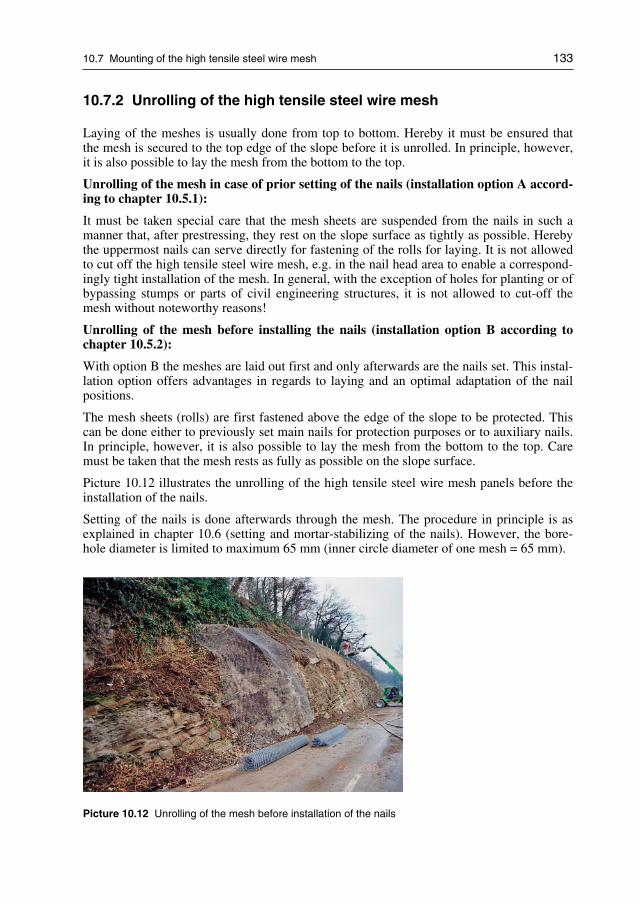
10.7 Mounting of the high tensile steel wire mesh 133
10.7.2 Unrolling of the high tensile steel wire mesh
Laying of the meshes is usually done from top to bottom. Hereby it must be ensured thatthe mesh is secured to the top edge of the slope before it is unrolled. In principle, however,it is also possible to lay the mesh from the bottom to the top.
Unrolling of the mesh in case of prior setting of the nails (installation option A accord-ing to chapter 10.5.1):
It must be taken special care that the mesh sheets are suspended from the nails in such amanner that, after prestressing, they rest on the slope surface as tightly as possible. Herebythe uppermost nails can serve directly for fastening of the rolls for laying. It is not allowedto cut off the high tensile steel wire mesh, e.g. in the nail head area to enable a correspond-ingly tight installation of the mesh. In general, with the exception of holes for planting or ofbypassing stumps or parts of civil engineering structures, it is not allowed to cut-off themesh without noteworthy reasons!
Unrolling of the mesh before installing the nails (installation option B according tochapter 10.5.2):
With option B the meshes are laid out first and only afterwards are the nails set. This instal-lation option offers advantages in regards to laying and an optimal adaptation of the nailpositions.
The mesh sheets (rolls) are first fastened above the edge of the slope to be protected. Thiscan be done either to previously set main nails for protection purposes or to auxiliary nails.In principle, however, it is also possible to lay the mesh from the bottom to the top. Caremust be taken that the mesh rests as fully as possible on the slope surface.
Picture 10.12 illustrates the unrolling of the high tensile steel wire mesh panels before theinstallation of the nails.
Setting of the nails is done afterwards through the mesh. The procedure in principle is asexplained in chapter 10.6 (setting and mortar-stabilizing of the nails). However, the bore-hole diameter is limited to maximum 65 mm (inner circle diameter of one mesh = 65 mm).
Picture 10.12 Unrolling of the mesh before installation of the nails

134 10 Project execution and installation
10.7.3 Vertical mesh connection
The mesh sheets can be laid out without overlap at the side.
The mesh sheets must be connected lengthwise (normally in the line of the slope) by meansof connection clips illustrated as follows on the next page (figures 10.6 and 10.7).
Hereby each individual edge-mesh must be secured with a single connection clip to theneighbouring mesh. Therefore there are 7 connecting clips per meter needed.
By this arrangement it is guaranteed that the lateral connection of the mesh sheets providesthe required transverse tensile strength of the mesh and that the deformations under load arelimited to an admissible degree.
Figure 10.6 Left: Connection with overlapRight: Connection with overlap of 2 diamond mesh units
Figure 10.7 Mesh panel connection with overlaps >2 diamond mesh units

10.7 Mounting of the high tensile steel wire mesh 135
10.7.4 Horizontal mesh connection
In principle there are two possibilities:
− Standard case: connection by turning-in of a wire spiral
− Alternative: connection by means of connection clips
10.7.5 Positioning of the spike plates
On positioning of the spike plates, care must be taken that the spike plates fit well betweenthe individual meshes and that they are firmly pressed into the ground. This ensures thatboth mesh and plate are optimally pressed to or against the ground to enable a correcttransmission of the forces.
Thereby, the mesh panels needs to be laterally attached to each other and installed in a tightmanner at first before the spike plates are going to be installed and actively pressed againstthe surface. If necessary, the mortar column in the nail head area needs to be removed ac-cordingly to enable a proper tensioning of the system.
Tightening the nut, individual wires could get stacked in the thread of the nail. In this case,the nut has to be loosened again trying to push the wire further against the subsoil after-wards.
Picture 10.13 demonstrates the appropriate positioning of a spike plate, set into the deeppoint and tightened correctly.
Picture 10.13 Positioning of spike plates
It is important that the system spike plate are applied correctly. It is important that theplates are positioned horizontally that a maximum of high tensile steel wires of the meshcan be covered. Figure 10.8 explain the great importance of the correct positioning.

136 10 Project execution and installation
Figure 10.8 Spike plates need to be oriented horizontally; long side must be horizontal (horizontalinstallation covers 16 steel wires, vertical installation covers only 8 steel wires)
10.7.6 Positioning of the spike plates in areas of hollows in theterrain
If a spike plate is positioned in the area of a hollow in the terrain, care must be taken againthat the spikes engage in the individual meshes evenly and in the best possible way (seealso picture 10.14 as an example).
If, due to the local topography as e.g. in the picture on the right, the mesh cannot be pressedfirmly onto the ground, the nails should be set as far as possible at a right angle to the meshsurface, so that the spike plates are more or less parallel to the mesh without provoking aone-sided strain on the mesh.
In such cases the pre-stressing force must be limited to maximum 30 kN.
Picture 10.14 Positioning of principal spike plates in areas of hollows (in the terrain surface)
10.7.7 Pretensioning of the slope stabilization system
By tightening the nut or with the aid of a hydraulic press, the spike plate and thereby themesh are firmly pressed onto the ground and the mesh is tensioned.

10.7 Mounting of the high tensile steel wire mesh 137
The load table 10.9 below shows a summary of the required torques for three different nailsof type GEWI for the application of a prestress force of V = 30 kN and V = 50 kN, respec-tively.
Nail type Pretensioning force V Required torque
GEWI D = 25 mm 30 kN 0.30 kNm 221 ft-lbs
50 kN 0.50 kNm 369 ft-lbs
GEWI D = 28 mm 30 kN 0.35 kNm 258 ft-lbs
50 kN 0.55 kNm 406 ft-lbs
GEWI D = 32 mm 30 kN 0.40 kNm 295 ft-lbs
50 kN 0.60 kNm 443 ft-lbs
Table 10.9 Load table for pretensioning of spike plates (1 kNm = 224.81 lbs · 3.281 ft = 737.6 ft-lbs)
Picture 10.15 shows the process of applying the pretension to the spike plate.
Picture 10.15 Pretensioning of spike plates
10.7.8 Fixation of the mesh edges
It is generally recommended to reinforce the edge areas of the mesh with boundary ropes.
The boundary ropes are secured to rope anchors located on the side and tensioned againstthese.
In case of irregular edges there may be a need under certain circumstances for short ordriven nails. These serve to tense the mesh to the soil as tightly as possible everywhere andto secure the edges in the best possible way.

138 10 Project execution and installation
The two schematic drawings (see figure 10.9) show the arrangement of the top, side andbottom boundary ropes and the rope anchor. Hereby the minimum distances of the bound-ary nails to the edge of the mesh are maintained correctly.
Figure 10.9 Principle drawing of side fixations of mesh edges
If the boundary nails are not continuing straight on or if the slope geometry is very irregu-lar, then, the boundary wire ropes on top as well as along the bottom should be installedalternating once above and once below the nails. Thus, a slipping out of the boundary wirerope underneath the spike plate can be avoided.
Fastening of boundary rope to rope anchors by means of wire rope clips
The boundary ropes must be fastened to the corresponding spiral rope anchors as per thefigure 10.10 below and according to DIN EN 13411-5 (2003) [41, 49].
Figure 10.10 Fixation principle of wire rope clips
The first wire rope clip is positioned immediately at the cable eye thimble. The wire ropeclips must be positioned at intervals so that a free space of minimum width t of one wirerope clip remains between each of them. The U-bolts must always be placed on the ropeend which is not tensioned (“never saddle a dead horse”).
Table 10.9 provides the required forces and numbers for the wire rope clips (according toDIN EN 13411-5).

10.7 Mounting of the high tensile steel wire mesh 139
Forces and number of wire rope clips
Nominal size[mm]
Required tighten-ing torque [Nm]
Required tighteningtorque [ft-lbf]
Required numberof wire rope clips
Spanner width[mm]
6.5 4 3 3 10
8 7 5 4 13
10 10 7 4 13
13 36 27 4 19
16 55 41 4 22
19 75 55 4 22
22 120 89 5 24
Table 10.9 Load table for pretensioning of spike plates (1 kNm = 224.81 lbs · 3.281 ft = 737.6 ft-lbs)
The stated tightening torques apply to greased thread and nut contact surfaces.
On installation and prior to commissioning the flanged nuts must be tightened to the speci-fied torque. After application of the first load the tightening torque must be checked oncemore and adjusted if necessary.
10.7.9 Fixation in combination with concrete foundation beam
Below a road or in special local conditions, the top of a TECCO slope stabilization systemcan be secured with a reinforced concrete beam. The following figures 10.11 and 10.12illustrate the corresponding construction and design.
Figure 10.11 Reinforced concrete beam at the top of the TECCO slope
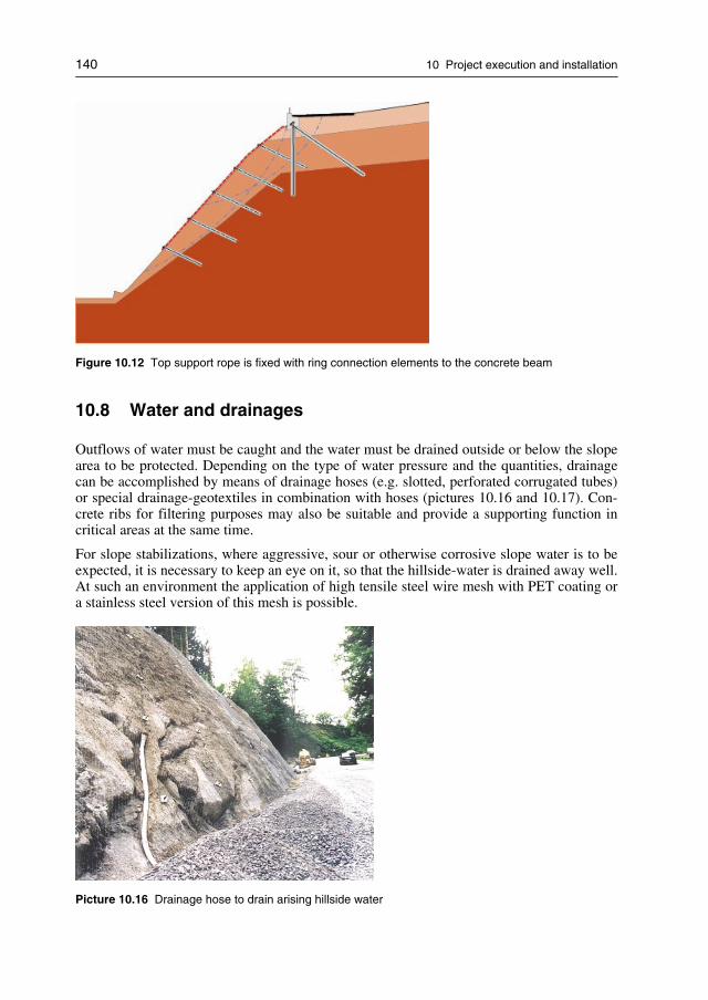
140 10 Project execution and installation
Figure 10.12 Top support rope is fixed with ring connection elements to the concrete beam
10.8 Water and drainages
Outflows of water must be caught and the water must be drained outside or below the slopearea to be protected. Depending on the type of water pressure and the quantities, drainagecan be accomplished by means of drainage hoses (e.g. slotted, perforated corrugated tubes)or special drainage-geotextiles in combination with hoses (pictures 10.16 and 10.17). Con-crete ribs for filtering purposes may also be suitable and provide a supporting function incritical areas at the same time.
For slope stabilizations, where aggressive, sour or otherwise corrosive slope water is to beexpected, it is necessary to keep an eye on it, so that the hillside-water is drained away well.At such an environment the application of high tensile steel wire mesh with PET coating ora stainless steel version of this mesh is possible.
Picture 10.16 Drainage hose to drain arising hillside water

10.9 Erosion control 141
Picture 10.17 Drainage hose to drain arising hillside water
10.9 Erosion control
In the case of fine-grained substrates with a strong tendency to erode, it is normally neces-sary to install a mat protecting against erosion so that protection is already provided fromthe moment the slope stabilization is installed. Some time usually elapses before greeningcan be carried out because it is uneconomical to do this work in smaller stages.
Erosion control measures are required if soil material can be flushed away in fine-grained,non- or insufficiently cohesive substrates. This erosion control may need to be of a tempo-rary (in case of subsequent greening) or permanent nature (without greening).
General assessment of the need for erosion control measures:
− Mandatory in cases of fine-grained, non-cohesive unconsolidated materials (e.g. silt,sand).
− Normally required in cases of mixed-grain, unconsolidated rolling materials (e.g. sand,gravel).
− Recommended in cases of relatively fine-grained soils if there is a risk of water flowingover the surface from areas above the slope stabilisation with the flexible high tensilesteel wire mesh.
− In general not required in cases of rocky slopes without loose rock or soil cover.
For protection against erosion, finer-meshed geogrids or structural mats must be installedbelow the mesh. Slopes with a risk of erosion, in general, need to be greened. The matsmust be matched to the intended greening process. Weather-resistant mats of plastic (pref-erably UV-stabilized PP, PE or PET) are generally used. With decomposing mats (jute,

142 10 Project execution and installation
sisal, coco fibre) we experienced some problems. The so called TECMAT Erosion ControlMat, consisting of Polypropylene, is specially designed and tested for the use with the hightensile steel wire mesh slope stabilization system (see Chapter 10.10.3).
The mats should only be opened in the area where the nails are passing through. Along theedges they should overlap by approx. 0.1–0.2 m. Bigger overlaps should be avoided.
The mats must be placed on the slope before the mesh is laid and can be secured by shortnails or with U-shaped pieces of reinforcing steel.
10.10 Greening, revegetation and planting
It can be desirable, recommended or mandatory to green and/or plant a slope where a flexi-ble slope stabilization system is installed.
Greening is always compulsory if the substrate is relatively fine-grained and endangered byerosion, and if flushing away of material (formation of erosion gutters) is expected duringrainfalls/snow melting periods. In such cases greening is an integral part of the entire miti-gation measure.
10.10.1 General assessment of the need of greening (technical view)
The following important points are recommended to be considered for the general assess-ment of the need of greening:
− Mandatory in cases of fine-grained, non-cohesive unconsolidated materials (e.g. silt,sand).
− Normally required in cases of all remaining substrates of unconsolidated material androcky slopes highly prone to weathering, particular in case of marl, siltstone, sandstone.
− Recommended in cases of rocky slopes of medium proneness to weathering, with dis-tinct layers and fissures.
− Not required in general for rocky slopes whose individual components (stones, blocks)are resistant to weathering and which the slope stabilisation system simply has to stopfrom sliding off and/or breaking out.
In fine-grained soils with a high risk of erosion, an erosion control mat must usually beinstalled to ensure there is erosion control immediately after the installation of the slopestabilization system. Some time usually elapses before greening can be carried out becauseit is uneconomical to do this work in smaller stages.
Erosion control mats may not be necessary if the stability can be guaranteed by the plannedgreening method, the type of vegetation layer and taking into account the point in timewhen greening becomes effective after the installation of the slope stabilization system.
Greening/planting may also be required for reasons of landscape preservation, for exampleif major new slope cuts must be recultivated. It is especially in these cases that the hightensile steel wire mesh slope stabilization system is chosen in combination with nailing asan alternative to larger, permanently visible engineering structures.

10.10 Greening, revegetation and planting 143
In the question of greening/planting, an aesthetic aspect can often take precedence oversafety-technical considerations.
Special remark:
Modern greening processes with special vegetation layers allow greening on substrates thatare less suitable for vegetation and/or under difficult climatic conditions. Such vegetationlayers are accordingly more elaborate and also more expensive.
10.10.2 Vegetation face
Greening of steep slopes as enabled by the high tensile steel wire mesh slope stabilizationsystem is in principle reserved for experienced specialists which already should be con-tacted in the planning stage. It is important that these experts are aware of the local circum-stances (climate, exposition, natural plant population, subsoil, etc.) and that they can matchthe vegetation face to these circumstances.
A prerequisite for successful greening is often the application of a minimum vegetationlayer to permit the plants to begin growing. This layer must be matched to the subsoil, theneed for nutrients and possibly other factors. It must be possible to apply this layer withfull-surface contact to the ground. The layer must be able to resist erosion a few hours afterthe application so that it cannot be flushed away by sudden heavy rainfalls. If erosion pro-tection mats are used, it is important to match the vegetation layer material to the mat insuch a way that penetration and filling of the mat is guaranteed.
10.10.3 Revegetation with erosions control mat
Dense mats of natural fibres, seed mats (with pre-greening) are normally not suitable forthese purposes unless the slope can be shaped very evenly so that the mats lie tightlyon the entire surface and are pressed against the slope by the high tensile steel wiremesh.
The TECMAT erosion control mat (see also chapter 8.9) is tested in detailed field studiesfor permeability of hydro and dry seed. Thus the TECMAT is the ideal solution for irregu-lar slopes.
The erosion control mat will be placed on top of the soil and fixed before installation ofthe main mesh. For irregular slopes it is required to fix the mat with soil nails to localdells (picture 10.18). This ensures an improved erosion control. The fixation is carriedout with soil nails of different length, depending on the thickness of the subsoil layer.Based on experience, it is recommend to install one soil nail every 3–6 m2. Along the edgesthe mats should overlap by approximately 0.1–0.2 meter and if required fixed with plasticties.
For the laying option B (laying of the meshes before setting of the nails) it is required to cuta hole with scissors in the erosion control mat to avoid snarl of the mat while drilling.

144 10 Project execution and installation
soil nails
local dells
Picture 10.18 Fixation of erosion control mat with soil nails
Auxiliary equipment and tools
− Long scissors for cutting of the mat panels to the appropriate length. Alternatively it ispossible to use a universal scissor with rechargeable battery (e.g. “Bosch”, GUS 9.6 V).
− Universal scissors to cut holes in the mat for drilling through.
− Sledge hammer (e.g. 4 kg) to drive in the soil nails
10.10.4 Seeding methods
The TECMAT erosion control mat is specially designed for greening with hydraulic or dryseeding respectively.
The main components of the hydro seeding are:
− seeds adapted to the soil and the climatic conditions
− biodegradable soil covering mulch (max. fibre length 3 mm)
− organic adhesive glue,
− purified, clean water
− if required, an organic-mineral fertilizer.
The materials will be mixed in the tank of a seeding machine to ensure homogeneity of themixture. After mixing, the material is sprayed in liquid form over the surfaces to be treated.For slopes with bad access or economically small areas, there is the option to do dry seed-ing with a so called “greening backpack” (picture 10.19). The components are seedsadapted to the soil and the climatic conditions, organic adhesive glue, if required, an or-ganic-mineral fertilizer.

10.10 Greening, revegetation and planting 145
In any case it is strongly recommended to contact a local greening specialist for successfulrevegetation.
Picture 10.19 Left: Example for hydraulic seeding machineRight: Greening backpack (hand machine) for dry seeding
10.10.5 Planting
In principle, the additional planting of shrubs (trees in exceptional cases only) is possible.This must be planned carefully and suit the particular location. There are various possibili-ties, ranging from dendro seeding, cuttings of vegetatively multiplying shrubs and trees(e.g. types of willows), to the planting of grown plants with roots.
Holes for trees
It is possible to integrate trees and equivalent crops in exceptional cases into the slope sta-bilization system. A cut out of the mat panel is sized accordingly to the crops. The cut out iscarried out after laying of the mesh panels. Thus the panel is open to the side and it is pos-sible to lay it around the crop. The two mesh panels are connected according to chapter10.7 with connection clips. Approximately two meshes from the cut edge, a boundary rope(diam. 8 mm) is seamed into the mesh. The boundary rope is connected at the end with 4pcs. NG 8 wire rope clips40.
The figure 10.13 and the picture 10.20 explain more detailed the recommended setup forholes for trees in a slope stabilization system with high tensile steel wire meshes.
40 Wire rope clip connections shall be done in accordance to DIN EN 13411-5 (2003) [41].

146 10 Project execution and installation
wire rope clipsNG 8
boundary rope8 mm
distance of two meshesto the boundary rope
overlap accordingto chapter 10.7
mesh panel 1 mesh panel 2
connection clips T3
Figure 10.13 Principle drawing for holes for trees or planting holes
Picture 10.20 Example for tree hole installation

10.10 Greening, revegetation and planting 147
Holes for planting
The planting of plants with roots (e.g. so-called container plants) is possible with adapta-tions to the mesh (after consultation with the mesh manufacturer). It is recommended toobtain the service of an experienced specialist for both planning and execution.
The plant holes will be carried out after laying of the mesh and before the final tensioningof the claw plates. The mesh is cut according to the size of the required opening. Fixationand installation is according to the description of tree holes.
10.10.6 Maintenance
Please note that every “green” solution in the form of greening/planting requires a minimalamount of maintenance. This is usually most intensive in the first two years and then de-creases, particularly in the case of planted slopes.
First cut
Indispensable for successful greening is a first nursing cut after the first full growth. Thisshould be done under all circumstances, otherwise there is a danger of the grass and herbsdrying and covering the slope in a manner restricting regrowth. The dry material can alsoresult in rot setting in underneath and encouraging moss to grow all over the slope.
This first cut must be made after a growth to a height of approx. 20–30 cm, and a cut levelof 10 cm should be maintained. Too short a cut can lead to drying up in droughts.
Cutting should generally not be done in hot weather or after long dry periods, as the gener-ally thin grass sod can easily dry out. A good time for cutting is in early autumn, after theend of the vegetation period.
Follow-up maintenance
In the first two years one cut per vegetation period is generally enough, and this preferablyalso in early autumn.
After two vegetation periods the long-term fertilizer is used up and an extensive vegetationadapted to the locally prevailing conditions forms. There is no strong growth anymore, so thatthere is generally no need for further maintenance with nursing cuts. Cuts may only be re-quired in parts of the slope from now on if subsequent inspections indicate a need for them.
Slopes with shrubs
Where shrubs are planted on slopes, maintenance in the first two vegetation periods is thesame as on slopes with grass.
Depending on the selected types, shrubs require a nursing cut at intervals of approx. 3–5years or whenever the periodic inspections show that it is necessary.
A nursing cut is also appropriate to guarantee a minimum incidence of light in the slope sothat the remaining greening (grass and herbs) does not disappear completely together withthe erosion protection and the stabilization by the roots.
If tall trees grow in the course of time, they must be felled since they might be blown overby strong winds. Dead wood must be removed.

148 10 Project execution and installation
General remarks regarding maintenance
More intensive maintenance in the first vegetation period encourages an optimal function ofthe vegetation and reduces the need for subsequent maintenance.
It makes sense to include maintenance with the 1st nursing cut and follow-up maintenanceduring two vegetation periods in the project and to have it offered as part of the scope ofperformance.
In this way it is possible to agree on a formal acceptance of the greening of the constructionafter expiry of these two vegetation periods and the company doing the work can be heldresponsible. Thereby one can practically exclude a low-cost offer of an inadequate greeningquality, since the supplier is aware of the pending assessment after two vegetation periods.Furthermore, experience shows, that a well-developed vegetation will continue to hold andgrow also after the two years.
10.11 Dells, hollows and recesses
Natural slopes can often have various types of dells, hollows and recesses. In this chapterseveral methods to ensure appropriate solutions for such cases are suggested.
Dells and recesses up to approx. 0.5 m
Whenever possible the nails should be set in low spots, so that the pre-stress pulls the meshcover into these. Major hollow spaces are thus avoided and in case of greening there is noneed to spray on an excessive quantity of vegetation layer material or filler material. If thenail pattern does not permit setting nails in low spots, it may be necessary to set additionalshort nails (figure 10.14).
Figure 10.14 Arrangement of the main nails and short nails in low spots

10.11 Dells, hollows and recesses 149
Hollows, dells and recesses deeper than 0.5 m
If the hollow spaces are too deep, prefilling with a special mixture to which concrete maybe admixed is possible before a vegetation layer is sprayed on. In this case the mesh doesnot need to be pressed or pulled right into the low spot.
Hereby care must be taken to ensure that the mesh upslope of the nail is tensioned so that agradient of no more than 75° results, otherwise correct greening is no longer possible.
Filling of hollows with a static task
If overhangs in rock, projecting blocks, etc. need to be secured statically, this can beachieved with sprayed concrete fillings secured as required with nails and if appropriatereinforced additionally with welded wire fabric (figures 10.15 und 10.16).
If these fillings are to be greened, the sprayed concrete surface should be at a level so thatthe high tensile steel wire mesh is tensioned at a distance of at least 10 cm above it. Thiswill allow the subsequent application of a sufficiently thick vegetation layer.
Figure 10.15 Detail arrangement in case of deep hollows with prefilling
Figure 10.16 Sprayed concrete fillings

150 10 Project execution and installation
10.12 Acceptance of the construction
10.12.1 Acceptance inspection
A general acceptance inspection must be carried out on completion of the work and beforethe possible application of a vegetation face.
Hereby the following must be checked:
Construction components
− The nails are correctly placed and grouted.
− The positions of the nails are adapted to the local topography in the best possible man-ner and the maximum admissible distances between nails are complied with the design.
− Nails must be placed in low spots whenever possible.
− Auxiliary nails are placed where necessary, in order to tense the mesh as much as possi-ble onto the surface.
− The nails are allowed to protrude by maximum approx. 20–25 cm.
− The system’s spike plates are installed correctly (horizontal alignment).
− The system’s spike plates are actively pressed onto the mesh and the substrate withoutbottoming on the nail itself due to e.g. a thread cut too short.
− The mesh is tensioned onto the surface to the best possible extent.
− The mesh sheets are fully connected without interruptions with the connection clips.
− Openings in the mesh e.g. for trees, adaptations to components, etc. are correctly closed.
− The boundary terminations are of a neat execution and the mesh is correctly fastened tothe boundary ropes.
− The boundary ropes are installed tightly and laterally tensioned against rope anchorswhenever possible.
− There is no evidence of unconformities (damaged/defective system).
Slope in general
− The system covers the critical area of the slope adequately in principle.
− Any drainage measures immediately above the protected slope and in the slope itself areof correct execution. Any observed outflows of water must be recorded in a protocol. Ifindicated, suitable supplementary work must be carried out to collect the arising waterand to drain it away in a controlled manner.
− If any signs of erosion are already evident, they must be recorded.
− Any more substantial movements in the fields between the nails must be recorded.
− Any fracture lines above the top boundary must be recorded.

10.13 Maintenance and periodic inspection of the flexible slope stabilization system 151
If any sort of construction sensitive to deformation (e.g. a road) is located above the flexi-ble slope stabilization, it is recommended as a matter of principle to provide a stiffeningmeasure in the form of e.g. a deep-anchored concrete partition in addition to the mesh coverin combination with nailing. If no such measure has been taken, the current condition mustbe recorded and the possibility of damage resulting from possibly inadequate protectionmeasures in the boundary area must be pointed out.
10.12.2 Acceptance protocol
Deficiencies detected during acceptance inspection must be eliminated by the executingcontractor and a formal final acceptance protocol must be issued and signed by the partiesinvolved (client, project editor, site manager and contractor).
Potential problem areas in the slope must be recorded in this acceptance protocol anddocumented with photographs, so that any changes can be detected during subsequent in-spections.
If required or desired, a vegetation face can be applied by means of a suitable process afteracceptance is completed. The acceptance inspection must be made beforehand becauseconstructive deficiencies within the system itself might otherwise be hidden by the sprayedon vegetation or greening layer.
10.13 Maintenance and periodic inspection of the flexible slope
stabilization system
10.13.1 Maintenance of the system
No maintenance as such is required if the slope stabilization system was correctly laid outand put in place and if suitable measures were taken against the problems of water outflowsand erosion.
The flexible stabilization system elements themselves require generally no maintenancethanks to their high-grade coating against corrosion.
Certain weathering and loosening processes are possible, however, since a protected slopeis also exposed to the influences of the environment (e.g. cycles of rains, frost, dew, etc.).Such effects cannot be prevented by the open high tensile steel wire mesh system, which iswhy it may become necessary to remove any fine material which has been washed to thefoot of the slope or rippled there.
Maintenance is actually only called for if inspections reveal mechanical damage to themesh or its fastening devices due to external influences. Such defects must be corrected.
If the mesh or a fastening feature has become loose, the problem can normally be solved byfurther tightening (tensioning). In extreme cases, additional nails may have to be put inplace.
If, in the extreme case, weathering, loosening and the influence of water have caused intol-erable material washout or movements with resulting hollows behind and pouches in the

152 10 Project execution and installation
meshes, the need for comprehensive maintenance including detaching of the meshes, emp-tying and re-installing must be considered. If appropriate, local hollows must be filled andstabilized with shotcrete.
10.13.2 Periodic inspection of the system
The periodic inspections must be specified within the framework of a maintenance sched-ule.
In the first two years an annual inspection should be carried out, preferably in spring. If twoconsecutive inspections reveal no major changes with a negative influence on the safetyand function of the protective construction, the intervals between the periodic checks can beextended to two years.
Additional inspections may have to be made after special events (e.g. after extreme rain-falls, falling of material over the protected slope and more severe seismic influences) inorder to detect damage to the system or major erosion and movements.
The periodic inspections comprise in the main:
− General condition
− Condition of problem spots according to the acceptance protocol
− Damage to the system itself (construction components)
− Damage due to erosion/movements in the context of the substrate
− Condition of the greening/vegetation (general/local)
− Documentation of defective areas/changes in relation to the previous inspections
The findings must be detailed in a protocol and documented by photographs so that changesfrom the condition at the time of the acceptance inspection and preceding inspections arerecorded.
Observing the weathering and erosion processes is important in slopes without greening orvegetation. In cases of local loosening or material erosion it must be checked whether thesituation can be improved by re-tensioning alone or additional measures such as securing ofhollows with shotcrete, greening, emptying of material deposits are called for. The criticalareas must be documented with photographs.
In slopes with greening or vegetation it must be checked how the plant life develops. Is thesurface covered completely, bare spots require re-greening. The need for maintenance(mowing, cutting back to the rootstock) must be determined.
10.14 Carbon footprint and environmental aspects
The climate change is increasingly recognized as a major global challenge. It is widelyaccepted that the greenhouse gas emissions caused by humans are having a negative impacton the environment [64].

10.14 Carbon footprint and environmental aspects 153
By far the most important greenhouse gas, arising from human activity, is carbon dioxide(CO2). Virtually all human activities cause the CO2 emissions that lead to climate change.By using electricity generated from fossil fuel power stations, burning gas for heating ordriving a petrol or diesel car, every person is responsible for CO2 emissions.
Furthermore every system, product or service consumed by humans indirectly creates CO2
emissions; energy is required for their production, transport and disposal. These products andservices may also cause emissions of other greenhouse gases. Understanding and addressingthe full range of our impact is crucial for the effects of climate change to be minimised.
The total set of greenhouse gas emissions caused directly and indirectly by an individual,organisation, event or product is commonly called their carbon footprint. Establishing thecarbon footprint of an organisation can be the first step in a programme to reduce the emis-sions it causes. This idea is aimed at helping businesses and organisations establish theircarbon impact and introduces some of the key issues faced in the calculation of a carbonfootprint.
10.14.1 What is a carbon footprint?
The term “carbon footprint” is commonly used to describe the total amount of CO2 andother greenhouse gas (GHG) emissions for which an individual or organisation is responsi-ble. Footprints can also be calculated for events, products or systems.
The full footprint of an organisation encompasses a wide range of emissions sources fromdirect use of resources and fuels to indirect impacts such as employee travel or emissionsfrom other organisations up and down the supply chain. When calculating a system’s foot-print it is important to try and quantify as full a range of emissions sources as possible inorder to provide a complete picture of the organisation’s or system’s impact.
In order to produce a reliable footprint, it is important to follow a structured process and toclassify all the possible sources of emissions thoroughly. A common classification is togroup and report on emissions by the level of control which a system or an organisation hasover them.
10.14.2 Why calculate a carbon footprint?
There are typically two main reasons for wanting to calculate a carbon footprint:
− To manage the footprint and reduce emissions over time
− To compare and report the footprint accurately to a third party.
Footprinting for management of emissions
Calculating an organisation’s carbon footprint can be an effective tool for ongoing energyand environmental management. If this is the main reason that an organisation requires acarbon footprint, it is generally enough to understand and quantify the key emissionssources through a basic process, typically including gas, electricity and transport. Thisapproach is relatively quick and straightforward. Having quantified the emissions, opportu-nities for reduction can be identified and prioritised, focusing on the areas of greatest sav-ings potential.

154 10 Project execution and installation
Footprinting for comparison and accurate reporting
Organisations increasingly want to calculate their carbon footprint in detail for public dis-closure in a variety of contexts:
− For public relation and/or marketing purposes.
− To fulfil requests from tender specifications, business or retail customers, or from inves-tors. This can especially be the case for public investments where the construction workfor new installations and maintenance has a big impact regarding the total carbon foot-print.
− To ascertain what level of emissions they need to offset in order to become “carbonneutral”. This can often be the case for private companies in order to distinguish fromcompetition.
Conclusions for construction and building processes
The importance of carbon footprint calculations and comparisons will increase in the nearfuture. It will become a more and more serious demand for any public organisation andprivate companies. Consequently, services, products and applied systems will have to bechecked, analyzed and compared regarding their carbon emissions. It is obvious that espe-cially the building and construction sector for infrastructure and maintenance have a bigimpact accordingly.
10.14.3 CO2footprint comparison between slope stabilizations
with shotcrete and with high tensile steel wire mesh
Two alternative slope stabilisation methods were analyzed in terms of their respective con-tribution towards the greenhouse effect (“climate friendliness”):
− A conventional slope stabilisation method, using shotcrete, anchors and welded wiremesh (see picture 10.21)
Picture 10.21 Slope stabilization using traditional reinforced shotcrete system

10.14 Carbon footprint and environmental aspects 155
− the slope stabilization with high tensile steel wire mesh (TECCO system, see also pic-ture 10.22).
Picture 10.22 Slope stabilization using high tensile steel wire meshes in combination with nailing(Tecco System)
In order to do this, the emissions which affect climate change and occur during the lifecycle of the building materials used as well as during the utilisation of the slope stabilisa-tion structures are to be logged and compared. This method is called the “CO2 footprint” asmentioned in the previous chapters 10.14.1 and 10.14.2. The “CO2 footprint” method usedhere essentially follows the Life Cycle Assessment (LCA) method in accordance with ISO14040.
The corresponding investigations, calculations and analysis were made by the Institute ofCivil and Environmental Engineering of the Technical University of Rapperswil in Switzer-land (Hochschule Rapperswil)
41.
The figures 10.17 and 10.18 show two comparable slope stabilisation structures, each real-ised by using one of the two methods to be compared.
These two structures are comparable in terms of:
− Functionality: the slope stabilisation function; other functions such as e.g. landscapeprotection will not be taken into consideration.
− Life cycle: both methods have the same service life.
− Maintenance/repairs: it has been assumed that neither of the methods will require anymaintenance/repairs to be carried out during their service life.
41 Details of this analysis are shown in the paper by Prof. Susanne Kytzia and Prof. Paul Hardegger of HSRHochschule Rapperswil [64].

156 10 Project execution and installation
Figure 10.17 Slope stabilisation using flexible slope stabilization system with high tensile steel wiremesh (TECCO System)
Figure 10.18 Slope stabilisation by means of shotcrete placement
Accordingly, the materials used for these two structures are listed on tables G.1 and G.2 inthe appendix G. These quantities correspond to a stabilisation structure consisting of a slope100 m long in each case as represented in the diagrams shown in figures 10.15 and 10.16.
The service life analysis was limited to the manufacture of the building materials and theirtransport to the construction site. Construction, operation, maintenance, removal and dis-posal were not be taken into consideration.

10.14 Carbon footprint and environmental aspects 157
This definition is based on the following considerations:
− Studies published on life cycle assessment of structures are based on the assumptionthat the creation of the structure will only make a relatively small contribution towardsthe pollution of the environment. Kasser [67] and Geiger and Fleischer [57] come to theconclusion that in the case of residential buildings, less than 1% of the cumulative ener-gy demand of a building can be attributed to construction. The construction of the struc-tures considered here is not expected to result in (relatively) higher energy expenditure.
− It has been assumed that in general, there will be no expenditure on operation and main-tenance.
− When the two structures are removed, it is mainly steel and concrete which will need tobe dealt with. If these two waste materials are collected separately, then their processingand disposal will only result in very low energy consumption and thus only to a lowlevel of emissions which might affect climate change.
The emissions from the manufacture of materials which might affect climate change (incl.the recovery of materials, the manufacture of fabricated materials and the supply of energy)as well as from transport processes have been taken from the Ecoinvent database from thedomain of the Polytechnical University ETH of Zurich, Switzerland. Within the context ofthis conservative estimate of emissions (consideration of the “worst case scenario”), in caseof doubt, processes which produce the highest level of environmental pollution was chosenin each case.
Emissions which might affect climate change have been selected by the level of carbondioxide emissions from the burning of fossil fuels (in kg of “CO2-fossil”) on the one hand.On the other hand, all the emissions which contribute towards climate change have beenrecorded and weighted according to their specific contribution – relating to carbon dioxideas a reference variable – and added together to give an overall index. This overall index isknown as the “Global Warming Potential” (“GWP” for short); the unit in which it is meas-ured is kg CO2 equivalent. This method of assessment has been used as part of the LifeCycle Assessment in many studies and is internationally recognized.
Results of the carbon footprint comparison
The comparison of all the emissions which might affect climate change during the servicelife of the two structures clearly shows that the TECCO system contributes to the green-house effect far less than the shotcrete placement (see Figure 10.19).
This statement applies to both “CO2-fossil” and to the “Global Warming Potential (GWP)”.The impact is around 4–5 times less for the TECCO system for both methods of as-sessment.
This difference can be attributed to the differences in the quantities of materials used. In theconstruction of the shotcrete placement, around 14,700 kg of steel, 40,300 kg of cement and564,000 kg of concrete are used. With the TECCO system, the same construction uses8,100 kg of steel and 23,400 kg of cement.
These differences have a considerable effect on the environmental impact which would becaused: both in respect of the manufacture of the materials and transport. These differencesare described in detail in the appendix G on table G.3. This also shows the different contrib-utions made by the different parts of the structure (nailing, mesh and shotcrete) as well asthe contribution of the different materials.

158 10 Project execution and installation
Comparison of the CO2 levels caused by different processes
0
20'000
40'000
60'000
80'000
100'000
120'000
140'000
160'000
Tecco Shotcrete Tecco Shotcrete
CO2 equivalent CO2 fossil
kg
Greening / drainage
Coating
Steel
Injection materials & concrete
Transport
Figure 10.19 Emissions which might affect climate change during the service life of a comparablestructure produced using different processes. The impact is around 4–5 times less for the TECCOsystem (compared to the shotcrete solution) for both methods of assessment.
This shows the following regarding the TECCO system:
− that nailing contributes towards the greenhouse effect far more than the mesh and greening;
− the cement used accounts for most of the total level of pollution caused, followed by thesteel (in a ratio of 3 to 1);
− the contribution made by transport is relatively small at 5% of the total level of pollu-tion caused.
This shows the following regarding the shotcrete structure:
− that the shotcrete accounts for 70% of the total level of pollution caused and thus con-tributes towards the greenhouse effect more than the pinning which accounts for 30% ofthe total level of pollution caused;
− the cement used is responsible for most of the total level of pollution caused, followedby the steel (in a ratio of 12 to 1);
− the contribution made by transport at approximately 9% is more than that made by thesteel.
10.14.4 CO2footprint comparison between slope stabilizations with
concrete and with high tensile steel wire mesh
The carbon footprint comparison analysis between slope stabilization systems with concretestructure and high tensile steel wire meshes [117] confirmed the results and conclusions ofthe previous chapter (10.14.3) in a similar way.

10.14 Carbon footprint and environmental aspects 159
The Kyoto Protocol to the United Nations Framework Convention on Climate Change is aninternational agreement negotiated on 11 December 1997 at the 3rd Conference of the Par-ties in Kyoto (Japan). The purpose is to require countries to lower their emissions of sixgreenhouse gases that cause global warming. Under the protocol, for instance, the countryof Japan is required to reduce greenhouse gas emissions by six percent compared to the1990 level over the period of 2008–2012. To achieve such targets, it is necessary to developinnovative technologies that produce less greenhouse gasses and emissions. The TECCOsystem, which offers slope stability with a high-strength mesh and soil nails, is expected asa less CO2-producing alternative measure than a conventional shotcrete technique, becausethe system requires less construction materials. Picture 10.23 show the two systems thatwere compared.
Picture 10.23 Compared systems for carbon footprint comparison in JapanLeft: Slope stabilization system with TECCO meshesRight: Concrete slope stabilization system (frame system)
The table G.4 (appendix G) shows the emission ratios of greenhouse gasses in each pro-cesses of concrete life cycle. As illustrated in the previous chapter and according to this, theemissions amount in a material manufacture process is extremely large compared withother processes. Moreover, source unit of CO2 emissions according to used material ineach system is shown in table G.542.
In addition, although the value of wire and steel bar was assigned directly, grout and shot-crete were comparatively converted based on the standard compounding ratio (w/c = 50%).The emission basic unit of the cement contained into them is 0.75kg-CO2/kg, sand is0.0034 kg-CO2/kg, water is 0.02 kg-CO2/m
3, and decided emission basic unit of grout andshotcrete from the quantity contained in per 1.0 m3.
The corresponding CO2 emissions in the material manufacture stage of the TECCO systemand the concrete frame system are calculated respectively based on the quantity of the usedmaterial per 1000 m2.
The calculation results are shown in the appendix G (table G.6). Material quantity of eachsystem was taken as the specification which can respond to shallow landslide level. For the
42 The CO2 emissions source unit of each material in table E.5 was extracted from “Center of EnvironmentalInformation Science corporation: Table of CO2 emissions standard physical unit”(2007) [29, 65].

160 10 Project execution and installation
high tensile steel wire mesh system, the nail interval is 2.5 m, and the nail length 2.1 m.The concrete frame set the beam interval to 2.0 m and the cross section to 300 × 300 mm.These are standard values for both systems.
Conclusion
According to this calculation result shown in appendix G (tables G.6 and G.7), the CO2
emissions of the high tensile steel wire mesh system in the material manufacture stage areapproximately 1/9, as compared with those of the shotcrete frame.
In other words, the adoption of the high tensile mesh system can reduce CO2
emission89% (figure 10.20).
Of course, this example may only illustrate a particular and single case. Country and/or areaspecific values and influences can cause additional variation of results. Nevertheless, thevery large difference of carbon footprint between high tensile steel wire mesh systems andcorresponding alternative solutions executed with concrete will always be significant.
Figure 10.20 Carbon footprint comparison between concrete and high tensile steel wire mesh slopestabilization systems

11 Practical examples
The following practical examples shall provide additional information about several fieldapplications and installation of projects that were designed according to the new method forthe design of slope stabilization systems with high tensile steel wire meshes. A selection ofexecuted projects is shown in order to illustrate various implementation aspects of the newmethod; therefore and for overview reasons, not all details of these projects are shown inthis chapter.
11.1 Project built at Anzenwil, Switzerland
Because of the new bridge at Anzenwil, the main road at the Neckartalstrasse betweenMogelsberg and Gantenswil had to be widened and therefore, the existing slope had to becut, prepared and secured.
Picture 11.1 provides an overview of the slope during installation of the flexible slope sta-bilization system. In the front, the old wooden bridge can be seen. The new bridge wasinstalled parallel to the old bridge where first concrete foundation is shown on the left sideof the picture.
Picture 11.1 Cut slope at the bridge of Anzenwil during the construction phase
Project and geotechnical data
Superficial friction angle (charact. value) ϕk
= 34 degrees
Friction angle (charact. value) ϕk = 32 degrees
Cohesion (charact. value) ck = 0 kN/m2

162 11 Practical examples
Unit weight (charac. value) γk = 20 kN/m3
Stabilized area A = 850 m2
Max. slope height H = 16.0 m
Slope length L = 50 m
Slope inclination actual state αbefore = 30–25°
Slope inclination final state αafter = 55°
Altitude = 700 m.a.s.
Exposition = south-west
The surface layers consisted of scree and moraine soil which covered the deeper layers ofmolasse (Nagelfluh) and marl material (figure 11.1).
Figure 11.1 General cross-section with nailing and high tensile mesh as protection system
Special local mountain water conditions with hillside water, water along stratification andjoint systems as well as several small slope springs required a careful design of the drainagesystem including water management. Consequently, additional dimensioning steps had tobe included for the design of the final slope stabilization system. The following figure 11.2provide additional overview information accordingly.

11.1 Project built at Anzenwil, Switzerland 163
Figure 11.2 General cross-section for stability analysis
Picture 11.2 Drainage measurements before mounting of the TECCO mesh

164 11 Practical examples
Picture 11.3 Completed slope stabilization system including greening (new bridge in front)
11.2 Project built at Mülheim, Germany
Close to the city of Mülheim (Germany), at the location Mendener Strasse, a rocky slopeapprox. 420 meter long and on average approx. 12 m high is permanently protected againstrockfalls and local instabilities by means of nailing in combination with a TECCO meshcover.
The inclination of the slope front to the horizontal plane amounts to between 45 and 70°.Locally, above all in the upper areas, the rockface (sandstone, siltstone, mudstone) is cov-ered by slope clay and slope scree (see also figure 11.3).
Figure 11.3 General cross-section with nailing and high tensile mesh as protection system

11.2 Project built at Mülheim, Germany 165
The rock is very prone to weathering. Based on the geotechnical situation, the overall sta-bility of the slope is not endangered. The protection measures are limited to the sectionclose to the surface.
The surface protection was dimensioned on the basis of the RUVOLUM method. For therocky section with a slope inclination of α = 70° and a long-term loosened, weathered layerof thickness t = 0.50 meter to be protected, a nail pattern of a = b = 2.5 meter resulted.
In the area of the unconsolidated rock covers with a slope inclination of 45–50° and witht = 0.80 m, a nail pattern of a = 3.3 m and b = 3.0 m resulted. The slope was greened withthe Fibrater system.
Picture 11.4 presents the situation with the closed road before the slope stabilization workstarted.
Picture 11.4 View of the slope and sliding areas before installation
The cleaning and natural grading with an excavator is shown on the following picture 11.5.
Picture 11.5 Cleaning and natural grading with excavator

166 11 Practical examples
The drilling machinery and drilling process is illustrated on the picture 11.6. Picture 11.7provides a partial overview of the installed high tensile steel wire mesh, shortly before thespike plates are finally tensioned.
Picture 11.6 Drilling process
Picture 11.7 Installation of high tensile steel wire mesh
Pictures 11.8 and 11.9 emphasize the natural and green appearance of a slope stabilizationsystem with high tensile steel wire mesh. Mesh and spike plates can hardly been seen onlyseveral months after installation due to natural greening effects.

11.3 Project built at Odernheim, Germany 167
Picture 11.8 Completed installation with protected slope
Picture 11.9 Completed installation with protected slope (rocky section)
11.3 Project built at Odernheim, Germany
Between the towns of Odernheim and Duchroth in Germany, a landslip occurred along theregional road L 235. This was followed by falling blocks, so that the road in question had tobe closed. Suitable measures to protect the particular slope permanently were called forurgently (see also picture 11.10). Protective measures taken in the area of the slope at anearlier stage had failed because, in the main, the applied nails were too short and conse-quently pulled out of the terrain together with the blocks. The fence of 2 m height along thefoot of the slope was intended as a rockfall barrier for rocks of maximum head size, but wasclearly not laid out for the events which subsequently occurred.
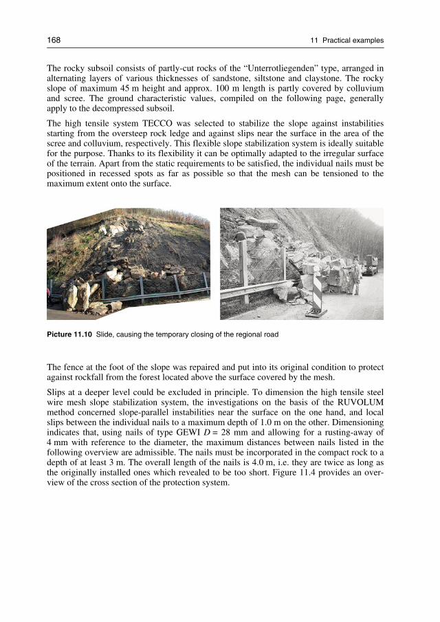
168 11 Practical examples
The rocky subsoil consists of partly-cut rocks of the “Unterrotliegenden” type, arranged inalternating layers of various thicknesses of sandstone, siltstone and claystone. The rockyslope of maximum 45 m height and approx. 100 m length is partly covered by colluviumand scree. The ground characteristic values, compiled on the following page, generallyapply to the decompressed subsoil.
The high tensile system TECCO was selected to stabilize the slope against instabilitiesstarting from the oversteep rock ledge and against slips near the surface in the area of thescree and colluvium, respectively. This flexible slope stabilization system is ideally suitablefor the purpose. Thanks to its flexibility it can be optimally adapted to the irregular surfaceof the terrain. Apart from the static requirements to be satisfied, the individual nails must bepositioned in recessed spots as far as possible so that the mesh can be tensioned to themaximum extent onto the surface.
Picture 11.10 Slide, causing the temporary closing of the regional road
The fence at the foot of the slope was repaired and put into its original condition to protectagainst rockfall from the forest located above the surface covered by the mesh.
Slips at a deeper level could be excluded in principle. To dimension the high tensile steelwire mesh slope stabilization system, the investigations on the basis of the RUVOLUMmethod concerned slope-parallel instabilities near the surface on the one hand, and localslips between the individual nails to a maximum depth of 1.0 m on the other. Dimensioningindicates that, using nails of type GEWI D = 28 mm and allowing for a rusting-away of4 mm with reference to the diameter, the maximum distances between nails listed in thefollowing overview are admissible. The nails must be incorporated in the compact rock to adepth of at least 3 m. The overall length of the nails is 4.0 m, i.e. they are twice as long asthe originally installed ones which revealed to be too short. Figure 11.4 provides an over-view of the cross section of the protection system.

11.3 Project built at Odernheim, Germany 169
Figure 11.4 General cross-section with nailing and high tensile steel wire mesh as protection system
Project information
Geotechnical parameters of the superficial area of the subsoil
Friction angle (charact. value) ϕk = 35 degrees
Cohesion (charact. value) ck
= 0 kN/m2
Unit weight (charac. value) γk = 23 kN/m3
Maximum nail distances using nails of type GEWI D = 28 mm
Inclination of slope α ≤ 55° > 55°
Max. nail distance horizontal a 3.00 m 2.50 m
Max. nail distance in line of slope b 3.00 m 2.50 m
Project data
Stabilized area 3′500 m2
Number of nails of type GEWI D = 28 mm 500 pcs.
Nail length 4.0 m
Total nail length 1,950 m
Time for installation 3.5 months

170 11 Practical examples
The picture 11.11 below illustrates an overview of the stabilized slope just by the end of theconstruction work and picture 11.12 presents the greened slope several months after thecompletion of the slope stabilization.
Picture 11.11 Overview stabilized area (after completion of installation work)
Picture 11.12 Overview stabilized area (several months after installation)
Picture 11.13 shows a closer view of the middle (steeper) part of the slope where mixedrock and soil sections are stabilized with the high tensile steel wire mesh system.

11.3 Project built at Odernheim, Germany 171
Picture 11.13 Detail from the middle steeper part (mixed rock and soil sections)
The location of nails and spike plates at low points in combination with intermediate steelwire ropes can be seen on the following picture 11.14.
Picture 11.14 Location of nail and spike plate in deep point of the slope

172 11 Practical examples
11.4 Project built on Island of Helgoland, Germany
In the North Sea, on the Island of Helgoland there is a steep East to South-East-facing rockslope of severely fissured sand and silt stone, the so-called “Falm” edge. The highly loos-ened rock material close to the surface endangers the properties located below the slope. Insome places loose layers of rock have already slipped away and partly backfilled and dam-aged several dwellings beneath (picture 11.15). The superficially very loose slope wassecured by means of the TECCO system consisting of the high tensile steel wire mesh andnailing (figure 11.5).
Picture 11.15 Sliding mass at the foot of the slope
Dimensioning was only carried out for the loosened layers of unconsolidated rock near thesurface and was based on the RUVOLUM method. Large-area, deep-seated stability prob-lems could be excluded in this case.
For the given example, using a nail of type GEWI 32 mm and taking into account a rusting-away of 4 mm off the diameter, the maximum admissible nail distances listed in table 2result in dependence of the slope inclination and at an assumed layer thickness of 1.0 m. Inthe area of the top cover layer nail lengths of 6.0 m were selected, and in the rock slopeitself generally of 4.0 m. Greening was indicated in view of this fine-grained and loosenedsubsoil highly liable to weathering.
The proximity to the sea with the salty, aggressive air demanded a mesh displaying a highresistance to corrosion, as it is guaranteed by the TECCO mesh with its aluminium-zinccoating. A much longer useful life can be expected from this mesh in comparison with onegalvanized in the normal manner.
Because of the complicated location above the residential areas with private houses, mostof the cleaning work had to be made by hand (figure 11.16).

11.4 Project built on Island of Helgoland, Germany 173
Figure 11.5 General cross-section with nailing and high tensile steel wire mesh as protection system
Picture 11.16 Cleaning work
Mesh installation and drilling processes had to be executed with special safety measure-ments in order to reduce impact to the houses and infrastructures below (picture 11.17).

174 11 Practical examples
Picture 11.17 Left: Installation of TECMAT and high tensile steel wire meshRight: Drilling processes with light weight equipment
The project information below provide an overview of the relevant design parameters.
Project information
Geotechnical parameters of the superficial area of the subsoil
Friction angle (charact. value) ϕk = 45 degrees
Cohesion (charact. value) ck
= 0 kN/m2
Unit weight (charac. value) γk = 24 kN/m3
Maximum nail distances using nails of type GEWI D = 28 mm
Inclination of slope α 55° 65° 80°
Max. nail distance horizontal a 3.65 m 3.00 m 2.35 m
Max. nail distance in line of slope b 3.65 m 3.00 m 2.35 m
Project data
Stabilized area 7′300 m2
Number of nails of type GEWI D = 28 mm 950 pcs.
Nail length 4.0–6.0 m
Total nail length 4,600 m
Time for installation 5 months
Pictures 11.18 and 11.19 show the slope several months after completion of the installationwork.

11.5 Project Kaiserslautern, Germany 175
Picture 11.18 Several months after greening
Picture 11.19 Overview of the slope stabilization of the Falm edge of Helgoland (Germany)
11.5 Project Kaiserslautern, Germany
A cutting was made in mottled variegated sandstone prone to weathering along the highwayA63 from Kaiserslautern to Mainz, Germany. This cutting is up to 30 m deep on the north-ern and 15 m on the southern side with a total area to be stabilized of 31′400 m2 [86]. Theinclination of the slope is generally 45° and flattens off slightly towards the top edge of theslope. The altitude amounts to about 220 m a.s.l. Transverse to the slope surface there areseveral fissures going right across, with a width up to several cm.
Relaxation processes in the form of removal of rock masses at the front led to a tremendousloosening of the rock compound with the result that the tectonic-based fissure systems were

176 11 Practical examples
visibly activated (see also pictures 11.20 and 11.21). Approx. two years after the excavationthe slopes revealed to be unstable and required subsequent protection measures.
Picture 11.20 Situation before stabilizing
Picture 11.21 Wedge-shaped failure due to relaxation
Figure 11.6 presents the cross section of the problem situation including the protectionmeasure.
The nailing as well as the flexible mesh cover were dimensioned on the one hand againstsuperficial instabilities considering various individual wedge-shaped bodies (figures 11.7and 11.8) susceptible to break out up to a depth of 4.5 m and of a width of up to 10 m vary-ing distances between fissures as well as based on the RUVOLUM method.

11.5 Project Kaiserslautern, Germany 177
Figure 11.6 Cross section including protection measure
Figure 11.7 Analysis of specific wedge-shaped failures
Figure 11.8 Investigation of the overall stability

178 11 Practical examples
On the other hand, the global stability was investigated according to the sliding-blockmethod (figure 11.9). As a result of the dimensioning, the maximum admissible nail spac-ing as well as the nail length minimum required were determined.
Figure 11.9 Investigation of individual wedge-shaped failures
Project information
Geotechnical parameters of the superficial area of the subsoil
Friction angle (charact. value) ϕk = 35 degrees
Cohesion (charact. value) ck
= 0 kN/m2
Unit weight (charac. value) γk = 23 kN/m3
Maximum nail distances using nails of type GEWI D = 32 mm
Inclination of slope α 45°
Max. nail distance horizontal a 3.40 m
Max. nail distance in line of slope b 3.40 m
Project data
Stabilized area 31′400 m2
Number of nails of type GEWI D = 32 mm 3′300 pcs.
Nail length 6.0–8.0 m
Total nail length 22′950 m
Due to the fact that the newly built highway could be used as a very comfortable accesswithout any restrictions and taking into account that the summer 2003 was extraordinarydry, the installation of both sections of a total area to be stabilized of 31′400 m2 took onlyabout three and a half months.
As a base for the determination of the required nail length as well as to guarantee the qual-ity of the fully mortared nails, numerous pulling tests were carried out. Pictures 11.22,11.23 and 11.24 show different views of installation locations and steps.

11.5 Project Kaiserslautern, Germany 179
To guarantee a full force transmission from one steel wire mesh panel to the neighbour one,special compression claws (picture 11.27) were used in accordance to the system instruc-tions.
To avoid any further erosion, a hydroseeding adapted to the local condition needed to beapplied as well. Thereby, the consideration of the regional micro climate was a very impor-tant factor for the selection of the seed to be applied. A part of the stabilized slope is shownon picture 11.25.
Picture 11.22 South-eastern slope: drilling work
Picture 11.23 Drilling work using mobile cranes

180 11 Practical examples
Picture 11.24 North-western slope
Picture 11.25 Stabilized slope
The slope stabilization system with high tensile steel wire mesh could be adapted to the sitespecific and static conditions in an optimal manner. It offers the possibility to arrange thenails in an economical way due to the capability of absorbing and transferring of highloads. Unlike stabilization with concrete solutions, with TECCO stabilized slopes regain anatural green appearance, which is well appreciated and more pleasant to the eye.

11.5 Project Kaiserslautern, Germany 181
Picture 11.26 Pulling tests
Picture 11.27 Connection of mesh panels

182 11 Practical examples
Designed to be maintenance free, the slope will further grow into the surrounding landscapeand contribute to a safe and economical operation of the highway. Numerous applicationshave proven that the fully designable TECCO system can ideally combine slope stabilizationwith revegetation measures tailored to the actual climatic and environmental conditions.
Based on the analyses of wedge-shaped failure mechanism as well as on the RUVOLUMmethod, the high tensile steel wire mesh system could be properly dimensioned againstsuperficial instabilities.
The following pictures 11.28 and 11.29 show the completed slope stabilization several monthsafter the installation. First results of the hydro-seeding can already be seen on the slopes.
Picture 11.28 State of the stabilized slope several months after installation
Picture 11.29 State of the stabilized north-western slope several months after installation

11.6 Project built at Grodziec Śląski, Poland 183
11.6 Project built at Grodziec Śląski, Poland
Several deep cuts were executed along the expressway S1 from Bielsko-Biała to the Polishborder with Czech Republic in Cieszyn. One of those cuts was characterized by flysh andclay soils prone to weathering and environmental exposure. According to the local waterand soil conditions, slope stabilization investigations and analysis were carried out andsolutions for global and surface stability were engineered.
Due to heavy and continuous rainfalls in autumn 2006, after the excavation and before thebeginning of the stabilization work, approximately one third of the slope surface failedand collapsed up to 3–4 meters deep. Moreover, in several locations on the slope surface,shallow slides were observed. After that, new design had to be prepared and submitted.This new concept included removement of down-slided soil material, fill-up of correspond-ing surface gaps and decreasing of inclination of the slope from 34 to 26 degrees. Finally,for the new slope stabilization, nailing and high tensile steel wire meshing was deter-mined. Accordingly, self-drilling soil nails (Titan 30/11) and the TECCO system wereapplied.
Project information
Name of project Express Road S-1, Grodziec Śląski/Poland
Slope height (in line of slope): max. 22 m
Geology: Flysch, clays
Slope angle: 1:2
Slope exposition: North and South
Protected area: approximately 8′600 m2
Measure type: Soil nailing together with flexible face cover made outof high tensile steel wire mesh
Investor: National Roads Dept., Division Katowice
General Contractor: SKANSKA S.A.
Nailing contractor: Soley Spółka z o.o.
Installation: 2007
Measure type: TECCO System
Mesh: TECCO G65/3 mm
Spike plates: TECCO System Spike Plates
Pretensioning force: V = 30 kN
Nails: TITAN 30/11
Nails length: L = 4, 6, 7, 8 m
Nails pattern: a · b = 2,5 m · 2,5 m

184 11 Practical examples
Pictures 11.30 and 11.31 show the self drilling processes on the slope and picture 11.32presents the installation of the high tensile steel wire mesh.
Picture 11.30 Drilling process from with access from the top of the slope
Picture 11.31 Slope under nailing works. Partially covered with crushed stones due to local failures ofthe slope surface

11.6 Project built at Grodziec Śląski, Poland 185
Picture 11.32 Installation of the high tensile steel wire mesh
On picture 11.33, the nail head area and the spike plates with the corresponding local dellsfor pretensioning are illustrated.
Picture 11.33 System spike plates allow active pretensioning (system fully installed)
The following pictures 11.34 and 11.35 show the express road with the slope stabilizationsystem. After several weeks, first results of greening can already be seen.

186 11 Practical examples
Picture 11.34 Slopes after completion. Slope partially covered with crushed stones, no greening wasapplied and no erosion mat was used
Picture 11.35 Completed slope after completion of Express Road works
11.7 Project Laliki, Poland
In the south of Poland at the express road S69 near Laliki, approximately 3′500 m2 of slopeis protected with combination of nailing and high tensile steel wire mesh surface cover.During planning the slope, at the very beginning of this project, the slope was somehowassumed to be a self-stable hard sandstone rockface. However, the following excavationand ground works asserted flysh as main slope material.

11.7 Project Laliki, Poland 187
The excavation works were partly done using explosives (picture 11.36) and this seems tobe the main reason why the face of the slope was partially heavy structured and fractured.Since it is often not simple to conduct geotechnical investigations and determine parametersfor flysh, so called Rock Lab analysis (figure 11.10) was conducted in order to obtain thegeotechnical parameters demanded for slope stabilization calculations. In a first concept,the entire area of approximately 7′000 m2 was considered to be stabilized.
Due to costs optimization, the project was changed from one angled plane (34°) to twoangled slope (45° in lower part and 26° in upper part of slope). The lower part acts asground retaining structure secured with nails and mesh. Both upper and lower part aredrained and revegetated.
Project information
Project name: Express Road S69, Laliki, Poland
Slope height: max. 6.0 m in nailed part, up to 15 m above the berm
Geology: Flysch, clays, sandstone
Slope angle: 45° (1:1) in nailed face, 26° (1:2) above the berm
Slope exposition: South
Protected area: approximately 3′500 m2
Measure type: Soil nailing together with flexible face cover made out ofTECCO, cocomat, hydro-seeding
General Designer: Transprojekt – Krakowskie Biuro Projektów Dróg i MostówSp. z o.o
General Contractor: BOGL & KRYSL Polska Spółka z o.o.
Nailing: Soley Spółka z o.o./PPI Gerhard Chrobok Sp.j.
Meshing and greening: AKG Architektura Krajobrazu Sp. o.o.
Installation: March–May 2009
Mesh: TECCO G65/3 mm
Spike plates: System spike plates (TECCO)
Pretensioning force: V = 30 kN
Nails: TITAN 40/16, L = 3–4.5 m
TITAN 30/11 L = 3, 6–9 m
Nail pattern: a · b = 1.5 m · 1.5 m
Cocomat type: GREENFIX Eromat typ 6S
The following charts show some results of the investigations that was done with Rock Labin order to obtain the relevant parameters of the flysh soil material.

188 11 Practical examples
Figure 11.10 Rock Lab investigation for flysh geotechnical parameters
Figure 11.11 Cross section of flysh slope protected with nails and TECCO system
The following picture 11.37 provides an overview of the reprofile slope surface includingthe self drilling nail heads (before installation of mat and mesh).

11.7 Project Laliki, Poland 189
Picture 11.36 Rough slope after cutting; the drainage system is visible at the upper part of the slopeover the bench
Picture 11.37 Reprofiled and nailed slope face
Picture 11.38 shows a view of the slope during the installation. Most cocomat cover isalready installed whereas the high tensile steel wire meshes are only partially unrolledon the surface. Picture 11.39 shows a slope three months after completion of installationwork.

190 11 Practical examples
Picture 11.38 Slope covered with cocomat during high tensile steel wire mesh installation
Picture 11.39 Picture of the slope three month after completion of installation work
11.8 Selection and samples of further TECCO projects
The following pictures shall give a wider overview of TECCO system installation andglobal application in different slope conditions.

11.8 Selection and samples of further TECCO projects 191
Picture 11.40 TECCO system installed at Brot-Dessous, Rochefort, Switzerland
Picture 11.41 TECCO system installed at Brot-Dessous, Rochefort, Switzerland

192 11 Practical examples
Picture 11.42 TECCO system installed at Dodoni, Greece
Picture 11.43 TECCO system installation at Polymilou, Greece (under construction)

11.8 Selection and samples of further TECCO projects 193
Picture 11.44 TECCO system installation at Santa Barbara, USA (under construction)
Picture 11.45 TECCO system installed at La Luz, Santiago de Chile

194 11 Practical examples
Picture 11.46 TECCO system installed at Dandong Highway, China
Picture 11.47 TECCO system installed at Gifu Prefecture, Japan

11.8 Selection and samples of further TECCO projects 195
Picture 11.48 TECCO system installed at Railway in Czech Republic
Picture 11.49 TECCO system installed for railway protection at Kyle, UK

196 11 Practical examples
Picture 11.50 TECCO system installed at Tunnel do Morro Agudo, Brazil
Picture 11.51 TECCO system installed at Tunnel do Morro Agudo, Brazil
Picture 11.52 TECCO slope stabilization at Carajas in Brazil (for VALE)

11.8 Selection and samples of further TECCO projects 197
Picture 11.53 TECCO system installation at Cavalcanti, Rio de Janeiro, Brazil
Picture 11.54 TECCO system installed at Barbados Wood, Tintern, USA

198 11 Practical examples
Picture 11.55 TECCO installation at open pit mine in Western Australia
Picture 11.56 TECCO installation at Mount Tambourine, Australia
Picture 11.57 TECCO installation at Puntilla Hydro Power Plant, Chile

11.8 Selection and samples of further TECCO projects 199
Picture 11.58 TECCO installation at Xativa, Spain
Picture 11.59 TECCO installation at Monte Rosa Cali, Colombia

200 11 Practical examples
Picture 11.60 TECCO installed at the Panama Channel, Panama
Picture 11.61 TECCO installation in Malaysia

11.8 Selection and samples of further TECCO projects 201
Picture 11.62 TECCO slope stabilizations incl. greening for SAMSUNG in Korea
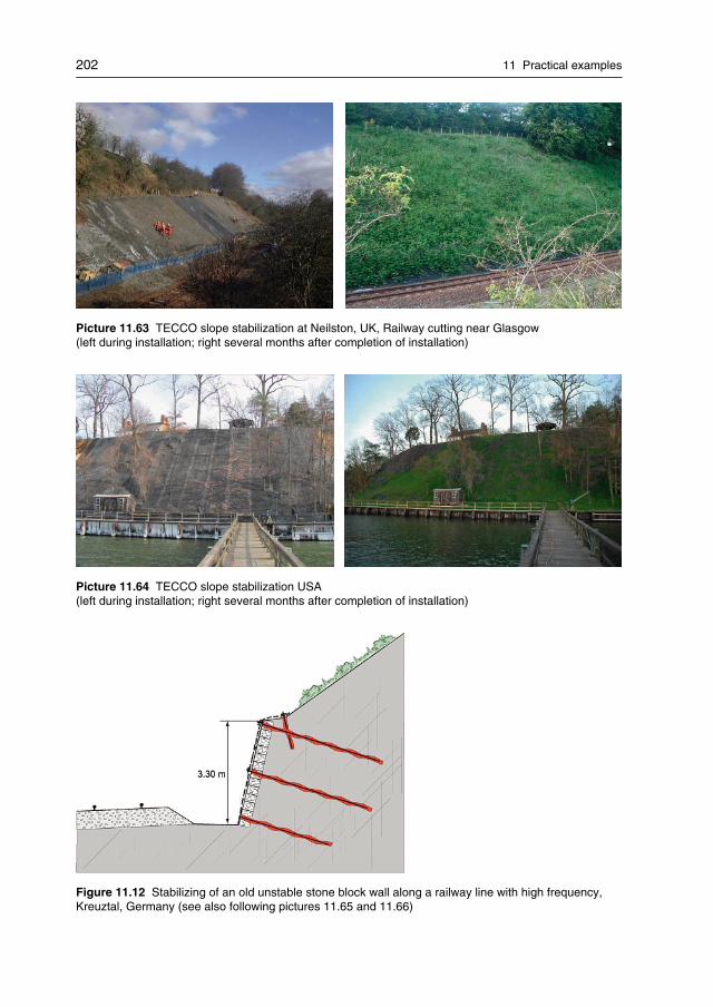
202 11 Practical examples
Picture 11.63 TECCO slope stabilization at Neilston, UK, Railway cutting near Glasgow(left during installation; right several months after completion of installation)
Picture 11.64 TECCO slope stabilization USA(left during installation; right several months after completion of installation)
Figure 11.12 Stabilizing of an old unstable stone block wall along a railway line with high frequency,Kreuztal, Germany (see also following pictures 11.65 and 11.66)

11.8 Selection and samples of further TECCO projects 203
Picture 11.65 Old, partly broken brick wall at railway line
Picture 11.66 Stabilized brick wall (covered and nailed with TECCO mesh)

204 11 Practical examples
Picture 11.67 TECCO stabilization of brick walls at Markgröningen, Germany
Picture 11.68 Special TECCO application at Alptransit exhibition centre, Bodio, Switzerland

11.8 Selection and samples of further TECCO projects 205
Picture 11.69 Slope stabilizations in Sendai area (close to Fukushima, Japan) after the heavy earth-quakes in March 2011. Left pictures shows a failed concrete slope stabilization due to earthquake influ-ences. Right pictures shows a TECCO slope stabilization that resisted all earthquake influences per-fectly without any damages.

206 11 Practical examples

12 Outlook and recommendation for furtherresearch
By means of the presented dimensioning models it is now possible in principle to dimen-sion so-called “flexible” surface protection systems in combination with nailing. Corre-sponding proofs of safety can be submitted for such systems provided that the necessaryinput quantities are known or have been established by suitably adapted tests for a specificsystem.
It is in the nature of the dimensioning models that they include substantial simplificationswhich can simulate reality to a limited degree only. Uncertainties are to some extent cov-ered by appropriate safety factors.
A future task is to check these dimensioning models and the forces calculated with their aidin appropriate large field tests and to make adaptations and/or fine tunings where necessary.
Scale 1:1 trials are suggested for this purpose on a test slope with the installation of anartificial cover layer to be stabilized. In the large-scale test it will then be possible to meas-ure both deformations and effective forces acting on the system, and to compare these withthe calculated values. Additionally, detailed and advanced geotechnical numerical simula-tions and calculations may support corresponding analysis.
These endeavours to establish the forces and to define adequate proofs of safety are in-tended to make the presented technique a recognized construction process which satisfiesthe usual requirements as regards the safety and “fitness-for-use” of a long-term construc-tion with permanent support and stabilization functions.
This will eventually permit to replace many elaborate conventional support and stabiliza-tion measures consisting of solid and visible constructions in a manner which is gentle onthe landscape and the environment.
Since the TECCO systems with high tensile steel wire meshes is containing substantialsafety factors, even more economic and cost-effective solutions may be achieved accord-ingly in the future.
Other than that, further research regarding design and application of the new dimensioningconcept for flexible slope stabilization systems should be made concerning application forrock slopes since meshes and nets from high tensile steel wires will also provide new po-tential for economical rock slope stabilizations.
Last but not least, new geotechnical numerical modelling in 2D and 3D will certainly sup-port analysis of the interaction between mesh, nails and soil/rock. Consequently, such newnumerical simulations will help with the design process of flexible slope stabilization sys-tems and should be studied more detailed in the future.

208 4 Überschrift 1

13 Summary and conclusions
The TECCO slope stabilization system with high tensile steel wire meshes is introduced inthis publication. The first chapters explain the traditional solutions using wire mesh andwire rope nets for slope stabilizations with flexible measure to protect surfaces. Also, thecorresponding dimensioning concepts including sliding off parallel to the slope, localwedge-shape bodies liable to break out and required inputs quantities and proofs of theterrain’s resistance against sliding (deep sliding surfaces) are presented and discussed.
High tensile steel wire meshes and their most common uses are then introduced, especiallywith the focus on flexible surface stabilization systems. Due to the uniform membranestructure of high tensile steel wire TECCO meshes, advanced nail patterns can be applied.The structure of the mesh enables to deviate from the basic pattern within reasonable limits;local discontinuities in the slope can be counteracted in optimum manner.
A new concept of load transfer around the nail head area is provided by the method of de-signing of flexible slope stabilization systems with meshes made from high tensile steel.Pretensioning is enabled by special spike plates and the high static effectiveness of the hightensile mesh itself. This allows substantially increased and optimized load transfers fromthe meshes into the plates and finally into the main nails which improves the static per-formance of the entire system and limits its deformations. Only meshes with high tensilesteel wires can be used accordingly; normal steel wire meshes tend to deform elastically,cannot distribute such pretensioning forces and will therefore not be able to transfer thenecessary loads which was illustrated with corresponding comparison tests.
The relevant material properties of high tensile steel wire TECCO meshes were determined,tested and analysed with corresponding test infrastructures, methods and comprehensivelaboratory tests. Externally supervised test series proofed the load bearing capacities of thesystem elements, their functioning and interactions.
Longterm field tests as well as different accelerated weathering tests were carried out inorder to ensure sufficient corrosion protection levels.
The dimensioning part of the RUVOLUM design method with TECCO mesh consists ofdifferent necessary investigations, load cases and stability proofs. This includes investiga-tions of superficial and local instabilities, puncturing and stability proofs as well as bearingcapacities of the nails. Additionally, the load cases “earthquake” and “streaming parallel tothe slope” were analysed and corresponding design methods developed and explained.Design examples provide an in-depth explanation with hand calculations of the entire di-mensioning concept.
A detailed description of typical project executions and installation options explain therecommended system elements, different planning steps problem analysis, preparation,stake-out, drilling, grouting, mounting and connecting the mesh to greening, revegetationand planting aspects. Also, important advise is given for acceptance, maintenance and peri-odic inspections of the flexible slope stabilization system.
Environmental and carbon footprint aspects are analyzed and discussed with comparisonsof all the emissions which might affect climate change during the service life of differentslope stabilization structures. It was shown that the TECCO system with high tensile steelwire mesh contributes to greenhouse effects far less than shotcrete or concrete structures. In

210 13 Summary and conclusions
that sense, increased use of such slope stabilization systems would definitely help to reduceand slow down global warming.
A few international examples of executed flexible slope stabilization solutions are pre-sented with various selected aspects of design, execution and installation in order to com-plete the introduction of the method of designing flexible slope stabilization system withhigh tensile steel wire meshes.
Conclusions about the TECCO system and the RUVOLUM method of designing of flexibleslope stabilizations with high tensile steel wire meshes:
− The method provides a slope protection and stabilization system which is used to stabi-lize slopes of any soil and unconsolidated, rocky material on the one hand, and on theother hand to prevent stones and blocks in disintegrated, loose or weathered rockfacesfrom breaking out.
− This design method serves dimensioning slope stabilization systems which consist ofhigh tensile steel wire mesh cover in combination with nailing. The dimensioning con-cept also includes the investigation of superficial slope parallel instabilities as well asthe investigations of local instabilities between the individual nails.
− Further, the design method provides a comparatively very low carbon footprint as wellas various visual advantages in order to allow respectful, environmental friendly andforward-looking solutions.
− In the meantime, installations and applications in more than forty different countries andon all continents demonstrate the method’s global geotechnical acceptance, approvaland economical effectiveness.

List of Appendices
Appendix A General overview drawing of TECCO system
Appendix B Data sheet of TECCO mesh
Appendix C Principle drawing of TECCO spike plate
Appendix D Principle drawing of T3 connection clip
Appendix E Example for high tensile steel wire test series
Appendix F Model tests regarding bearing resistances
Appendix G Material description and calculation of carbon footprint analysis andcomparison
Appendix H Example for output data of Dimensioning RUVOLUM Software

212 List of Appendices
Appendix A General overview drawing of TECCO system

List of Appendices 213
Appendix B Data sheet of high tensile steel wire mesh

214 List of Appendices
Appendix C Principle drawing of TECCO spike plate

List of Appendices 215
Appendix D Principle drawing of connection clip

216 List of Appendices
Appendix E Example for high tensile steel wire test series
Since the beginning of production of high tensile steel wire meshes, raw material control ofsteel wire was and still is always of great importance. All production companies are carry-ing out random tests to check their provided technical information.
For example, BAREMO GmbH (Romanshorn, Switzerland) is one of the independentcompanies for material testing. This company is testing the wire samples in accordance tostandard DIN 51210 to verify the technical information provided by the steel wire supplier.Thereby, the following tests are being carried out:
− Tensile tests at an individual steel wire (determination of the breaking load)− Bending tests− Torsion tests− Determination of the corrosion protection coating thickness
To analyse the probabilistic distribution of the tensile strength of the high-tensile steel wire,the provided data by the steel suppliers is evaluated and summarized. In order to give anoverview of this procedure, a sample of a French supplier of wires is illustrated as follows:
− Number of considered coils: n = 139− Average value of the yield strength (under tensile load) f
y= 1860.6 N/mm2
− Minimum value of the yield strength (under tensile load) fy,min = 1783.0 N/mm2
− Maximum value of the yield strength (under tensile load) fy,max = 1920.0 N/mm2
− Standard deviation s = 25.33 N/mm2
Evaluation of the yield strength of TECCO steel wire
1750
1770
1790
1810
1830
1850
1870
1890
1910
1930
1950
0 20 40 60 80 100 120 140 160
Number of Coils
Yieldstrengthf y[N/mm2]
Figure E.1 Probabilistic evaluation of the tensile strength of supplied coils of high tensile steel wire(used for TECCO mesh)

List of Appendices 217
Appendix F Model tests regarding bearing resistances
Based on the RUVOLUM method, flexible slope stabilization system such as the TECCOsystem, can be dimensioned against superficial instabilities. Next to slope-parallel failuremechanisms, local instabilities between the single nails are investigated.
Based on practical experiences as well as experiences during model tests (figure F.1), it isgenerally assumed that if a certain mass would slide down, tensile forces in the mesh occuras a result of friction or interaction, respectively, between the subsoil and the mesh. Aboveof the considered sliding mechanism, the wire mesh is fixed at the nail head with a TECCOsystem spike plate. A certain amount of this tensile forces are transferred from the wiremesh via the spike plate onto the nail and finally into the stable subsoil. This additionalstabilizing effect can be taken into account in the consideration of equilibrium in the con-text of superficial instabilities.
To determine the maximum possible tensile force to be transmitted from the steel wiremesh via the TECCO system spike plate onto the nail, corresponding tests as presented inpicture F.1 were carried out. It is important to differentiate between the capacity of the wiremesh to this kind of local force transmission and the tensile strength of the steel wire meshin longitudinal as well as transversal direction. During the tensile tests, the stress transmis-sion is more or less uniform over the width of the test sample. In contrast to this, in the testsas shown in picture F.1, the load distribution is concentrated very much around the nailhead.
The bearing resistances of the steel wire mesh to tensile stress in longitudinal as well astransversal direction mainly serve to characterize the product. But this information cannotbe used directly for the dimensioning of the stabilization system against superficial insta-bilities because the effective kind of stresses occur in different ways.
Figure F.1 Left side: model for the investigation of local instabilities between the single nails based onthe RUVOLUM method.Right side: model tests with a scale of 1 :5 with an inclined plane. The photographs on the very rightside shows the deformation behaviour of the system around the nail head area in a near vertical state.Just below the thread bar, a hole was created due to moving down of the sandy material. The geogrid istensioned and pulls at the nail head. At the same time on the upper side of the steel plate, the geogridwould like to be sheared off. The sliding mass is pushing out the flexible system. In this test, the resist-ance of the system against shearing-off is sufficient. But of course, a geogrid should not be used forstabilizing real slopes due to its low resistance. In this model test, it was not possible to use a scaledTECCO mesh.

218 List of Appendices
Picture F.1 Test setup to determine the bearing resistance of the high tensile steel wire mesh systemagainst selective, slope-parallel tensile stress. In this test series, the tensile forces have to be transmit-ted from the pulling machine, via wire ropes and shackles, the steel frame and the steel wire mesh ontothe spike plate as well as the nail into the subsoil. The box filled up with sandy gravel and the centralarranged nail with the spike plate are fix. The red frame and the attached steel wire mesh TECCO canmove freely on the green steel profiles

List of Appendices 219
Appendix G Material descriptions and calculation of carbon footprint analysisand comparison
TECCO – System Material Weight(kg)
Pinning(WT 32 gross)
Nail = 4.0 m steel 1817.3
Nail = 6.0 m steel 4088.9
Injection for nails cement, w/c = 0.4 23400.0
Wire mesh
TECCO mesh high-strength wire 1963.6
Corrosion protection:galvanization
zinc 169.6
Corrosion protection:galvanization
aluminium 8.9
Gripping plate sheet steel 495.0
Corrosion protection forgripping plate
zinc coating
Press claws steel 123.8
Corrosion protection zinc coating
Stranded rope(as side guys, top/bottom)
high-strength wire 100.0
Corrosion protection forstranded rope
zinc coating 0.5
Spiral rope anchor = 4.0 m(top/bottom)
high-strength wire 42.4
Corrosion protectionfor spiral rope anchor
zinc coating 0.2
Injection for spiral ropeanchors
cement 896.0
Planting
TECMAT erosionprotection mat
polypropylene 714.0
Table G.1: Materials used for a slope stabilisation structure constructed using flexible Tecco wire net-ting for a slope 100 m long

220 List of Appendices
Shotcrete placement Material Weight
(kg)
Pinning (WT 28 gross)
Nails = 4.0m steel 1081.9
Nails = 5.0m steel 6713.7
injection for Nägel cement, w/c = 0.4 40350.0
Shotcrete
Total shotcrete(spraying loss ~25%)
564360.0
Clips Steel 6324.8
Top plate Steel 589.2
Corrosion protectionfor top plate
Zinc coating
Drainage
Drainage pipes PVC 64.0
Table G.2 Materials used for a slope stabilisation structure constructed using shotcrete placement for aslope 100 m long
Consideration of the CO2equivalent level of pollution (in kg CO2 equivalent)
Tecco-System
Process Total Pinning Mesh Planting
Total for all processes 35586.6 28041.0 6037.6 1508.0
Portland cement, strength class Z 42.5,at plant/CH S
20245.2 19498.6 746.6 0.0
Reinforcing steel, at plant/RER S 8134.6 7363.1 771.4 0.0
Steel, converter, low-alloyed, at plant/RER S 3571.8 0.0 3571.8 0.0
Transport, lorry 28t/CH S 1644.0 1179.3 385.1 79.5
Polypropylene, granulate, at plant/RER S 1428.5 0.0 0.0 1428.5
Zinc for coating, at regional storage/RER S 437.1 0.0 437.1 0.0
Aluminium, primary, at plant/RER S 106.4 0.0 106.4 0.0
Transport, transoceanic freight ship/OCE S 19.2 0.0 19.2 0.0
Table G.3 Detailed consideration of the emissions which might affect climate change during the servicelife of a comparable structure produced using different processes

List of Appendices 221
Shotcrete placement
Process Total Shotcrete Pinning Drainage
Total for all processes 147479.6 102231.2 45108.6 139.8
Concrete, exacting, at plant/CH S 80772.4 80772.4 0.0 0.0
Portland cement, strength class Z 42.5,at plant/CH S
33622.5 0.0 33622.5 0.0
Reinforcing steel, at plant/RER S 18338.2 8619.6 9718.6 0.0
Transport, lorry 28t/CH S 14578.7 12809.8 1767.5 1.4
Polyvinylchloride, at regional storage/RER S 138.4 0.0 0.0 138.4
Zinc for coating, at regional storage/RER S 29.5 29.5 0.0 0.0
Consideration of the CO2pollution from fossil fuels (in kg CO2 )
Tecco-System
Process Total Pinning Mesh Planting
Total for alle processes 25053.4 22040.0 2949.8 63.6
Transport, lorry 28t/CH S 1282.6 920.0 300.5 62.1
Transport, transoceanic freight ship/OCE S 0.2 0.0 0.2 0.0
Portland cement, strength class Z 42.5,at plant/CH S
18586.0 17900.0 686.0 0.0
Reinforcing steel, at plant/RER S 3557.4 3220.0 337.4 0.0
Steel, converter, low-alloyed, at plant/RER S 1522.7 0.0 1522.7 0.0
Polypropylene, granulate, at plant/RER S 1.5 0.0 0.0 1.5
Zinc for coating, at regional storage/RER S 85.9 0.0 85.9 0.0
Aluminium, primary, at plant/RER S 17.0 0.0 17.0 0.0
Shotcrete placement
Process Total Shotcrete Pinning Drainage
Total for all processes 122480.4 85960.0 36518.0 2.5
Transport, lorry 28t/CH S 11372.3 9993.2 1378.0 1.1
Concrete, exacting, at plant/CH S 72200.0 72200.0 0.0 0.0
Portland cement, strength class Z 42.5, atplant/CH S
30900.0 0.0 30900.0 0.0
Reinforcing steel, at plant/RER S 8001.0 3761.0 4240.0 0.0
Polyvinylchloride, at regional storage/RER S 1.4 0.0 0.0 1.4
Zinc for coating, at regional storage/RER S 5.8 5.8 0.0 0.0
Table G.3 Continued

222 List of Appendices
Process CO2 emissions(%)
SOX emissions(%)
NOX emissions(%)
Soot and Dustsemissions (%)
Material 84.9 63.2 40.6 27.9
Construction 4.9 9.5 16.0 19.2
Dismantlement 5.3 14.9 28.7 31.4
Abandonment andrecycling
1.2 1.9 1.6 2.1
Transportation 3.6 10.5 13.1 19.4
Table G.4 Process rate of concrete life cycle
Emission basic unitIndustrial method Material
Value Unit
Grout 937.6 kg-CO2/m3
Wire 1.3 kg-CO2/kg
High tensile steel wire mesh system
(TECCOsystem)
Steel bar 1.2 kg-CO2/kg
Grout 937.6 kg-CO2/m3
Shotcrete (mortar) 320.7 kg-CO2/m3
Wire 1.3 kg-CO2/kg
Concrete/shotcrete system
Steel bar 1.2 kg-CO2/kg
Table G.5 CO2 emissions source unit of each material
Use quantity CO2emissionsstandard physical unit
CO2
emissionsMethod ofconstruction
Material
Quantity Unit Value Unit (kg-CO2)
Grout 0.9 m3 937.6 kg-CO2/m3 844
Wire 2,124.0 kg 1.3 kg-CO2/kg 2,761
Steel bar 2,775.0 kg 1.2 kg-CO2/kg 3,330
TECCOsystem
Total 6,935
Grout 1.4 m3 937.6 kg-CO2/m3 1,313
Shotcrete/concrete(mortar)
141.0 m3 320.7 kg-CO2/m3 45,219
Wire 4,463.0 kg 1.3 kg-CO2/kg 5,802
Steel bar 11,167.0 kg 1.2 kg-CO2/kg 13,400
Concrete frame
Total 65,734
Table G.6 Calculation results of CO2 emissions per 1′000 m2 slope surface

List of Appendices 223
TECCOsystem
CO2emissions (A)
Shotcrete
CO2emissions (B)A
B
Reduction rate
( )( )
-¥
B A
B100 %
6,935 kg-CO2 65,734 kg-CO2 6.935/65.734 = 1/9.5 (65.734 – 6.935)/65.734 × 100= 89.4%
Table G.7 Environmental impact by high tensile steel wire mesh system (TECCO system)

224 List of Appendices
Appendix H Example for output data of RUVOLUM DimensioningSoftware (1/4)

List of Appendices 225
Appendix H Example for output data of RUVOLUM DimensioningSoftware (2/4)

226 List of Appendices
Appendix H Example for output data of RUVOLUM DimensioningSoftware (3/4)

List of Appendices 227
Appendix H Example for output data of RUVOLUM DimensioningSoftware (4/4)

228 List of Appendices

List of References
[1] Abramson, L. W.; Thomas, S. L.; Sharma, S.; Boyce, G. M.: Slope stability and stabilizationmethods. John Willey & Sons Inc., New York, USA, 1996.
[2] Apel, G.; Nünninghoff, R.; Sczepanski, K.: Galfan – ein neuer Korrosions-schutz für Seile,Draht 39 (1988) Nr. 4 + 5, Germany, 1988.
[3] American Society for Testing and Materials, ASTM B117: Saltspray Accelerated WeatheringTest, USA, 2003.
[4] American Society for Testing and Materials, ASTM A-975: Hexagonal Steel Wire Meshes,USA, 2003.
[5] Bachmann, H.: Stahlbeton, Vorlesungen Abteilung Bauingenieurwesen der ETH Zürich, IBK,Institut für Baustatik und Konstruktion, Swiss Federal Institute of Technology, Switzerland,1991.
[6] Balcerek, B.: Wybrane problemy ochrony środowiska w drogownictwie – Selected environ-mental problems in road industry, Pages 60–67, Polskie Drogi – Polish Roads No. 12 (148),Poland, 2007.
[7] Balcerek, B.: Umacnianie skarp drogowych a sprawność systemu odwodnienia i podczyszcza-nia wód – Strengthening of the road slopes, drainage system and the efficiency of water pre-treatment, Pages 86 – 90, Polskie Drogi – Polish Roads No. 5 (172), Poland, 2010.
[8] Baraniak, P.; Mrozik, M.: Konstrukcje chroniące przed spływami gruzowymi oraz spadają-cymi odłamkami skalnymi – testowanie, wymiarowanie, instalacja, użytkowanie – Protectionsystems against debris flow and rockfalls – testing, dimensioning, installation, exploitation,Konstrukcje stalowe w geotechnice – Steel structures in geotechnics, pages 79–88; Poland,2010.
[9] Bergische Universität Wuppertal, Germany; Prof. Dr.-Ing. Rolf Nünninghoff: Test Report No.9811, GALFAN-coated steel wire mesh in alkaline environment, Longterm field study report3/2004, Germany, 2004.
[10] Bergische Universität Wuppertal, Germany; Prof. Dr.-Ing. Rolf Nünninghoff: Test Report No.9811, Comparison between different different corrosion laboratory tests Zn-coated and Zn–Al-coated steel wires, Germany, 2006.
[11] Böhni, H.: Werkstoffe I, Vorlesung Abteilung Bauingenieurwesen der ETH Zürich, IBWK,Institut für Baustoffe, Werkstoffchemie und Korrosion, Swiss Federal Institute of Technology,Switzerland, 1994.
[12] Böhni, H.: Werkstoffe IV, Vorlesung Abteilung Bauingenieurwesen der ETH Zürich, IBWK,Institut für Baustoffe, Werkstoffchemie und Korrosion, Swiss Federal Institute of Technology,Switzerland, 1995.
[13] Brändlein, P.: Monitoring and supervision of laboratory testing of TECCO mesh and systemcomponents. LGA Nuremberg, Germany, Test report BGT 0230101, Germany, 2003.
[14] Brisbé York, A. M.; Flum, D.; Roth, A.; Roduner, A.: RUVOLUM Dimensioning Software7.0, Spain and Switzerland, 2006.
[15] Bromhead E. N., Landslide slip surfaces: their origins, behavior and geometry, Landslides:Evaluation and Stabilisation (edited by Lacerda, Erlich, Fontura & Sayao), Taylor & FrancisGroup, London, pp. 3–21, Rio de Janeiro, 2004.

230 List of References
[16] Bundesamt für Umwelt, Wald und Landschaft BUWAL und Eidgenössische ForschungsanstaltWSL: Typenliste Ankermörtel; Ankermörtel, die für den Lawinenverbau und Steinschlagver-bau zugelassen sind, Switzerland, 2004.
[17] Bundesamt für Umwelt, Wald und Landschaft BUWAL und Eidgenössische ForschungsanstaltWSL: Lawinenverbau im Anbruchgebiet – Technische Richtlinie als Vollzugshilfe, Switzer-land, 2007.
[18] Cała, M.; Flisiak, J.: Slope stability analysis with FLAC and limit equilibrium methods, Pro-ceedings of the 2nd Geomechanical International Symposium, Lyon, France, 2001.
[19] Cała, M.; Flisiak, J.; Tajduś, A.: Slope stability analysis with modified shear strength reductiontechnique. Landslides: evaluation and stabilization. Proceedings of the ninth internationalsymposium on Landslides, 2004, eds. Willy A. Lacerda [et al.]. Taylor & Francis Group, Lon-don, pp. 1085–1089, Rio de Janeiro, 2004.
[20] Cała, M.; Roth A.: Możliwości zastosowania siatek stalowych w warunkach zagrożeń dy-namicznych. Górnictwo i Geoinżynieria, Vol 31, z. 3, pp. 125–134. Poland, 2007.
[21] Cała, M.; Flisiak, J.; Tajduś, A.: Slope stability with FLAC in 2D and 3D. Proc of 4th Int.FLAC Symposium. FLAC and Numerical Modeling in Geomechanics. Itasca ConsultingGroup. Madrid., Spain, 2006.
[22] Cała, M.: Convex and concave slope stability analysis with numerical methods. Archives ofMining Sciences. Vol. 52, Issue 1. pp. 75–89. Wydawnictwo Instytutu Mechaniki GórotworuPAN. Kraków, Poland, 2007.
[23] Cała, M.: Numeryczne metody analizy stateczności zboczy. Wydawnictwa AGH, seria ro-zprawy i monografie nr 171. Kraków, Poland, 2007.
[24] Cała, M.; Kowalski M.: Reinforced slope stability analysis with FLAC, Continuum and dis-tinct element numerical modeling in geo-engineering, Proceedings of the 1st internationalFLAC/DEM Symposium, USA, 2008.
[25] Cała, M.; Kowalski M.: Reinforced slope stability analysis with FLAC, Geobrugg AnnualConference 2008, Switzerland, 2008.
[26] Caprez, M.; Dietrich, K.: Geotechnik und Strassenbau, Institut für Verkehrsplanung, Trans-porttechnik, Strassen- und Eisenbahnbau, IVT, Eidgenössische Technische Hochschule, Poly-technical University of Zurich, Switzerland, 1996.
[27] Chen F. H., Soil Engineering, Testing, Design and Remediation, CRC Press, Boca Raton FL,2000.
[28] Cheng Y. M.; Lansivaara T.; Wei W. B.: Two-dimensional slope stability analysis by limitequilibrium and strength reduction methods, “Computers and Geotechnics”, Vol. 34, pp. 137–150, 2007.
[29] Center of Environmental Information Science: Table of CO2 emissions standard physical unit(version 2007), Japan, 2007.
[30] Dawson E. M.; Roth W. H.: Slope stability analysis with FLAC, 1999, FLAC and numericalmodeling in geomechanics (edited by Detournay & Hart). A. A. Balkema, Rotterdam, pp. 3–9,Netherlands, 1999
[31] Drzymała, I.: Problemy z osuwiskami – Problems with landslides, Autostrady – HighwaysMagazin, 7/2009, Poland, 2009.
[32] Duncan J. M.; Wright S. G.: Soil strength and slope stability, John Wiley & Sons Inc., Hobo-ken, New Jersey, USA, 2005.

List of References 231
[33] DIN 1055-100: Einwirkung auf Tragwerke – Grundlagen der Tragwerksplanung – Sicher-heitskonzept und Bemessungsregeln, 2001.
[34] DIN 1055-9: Einwirkung auf Tragwerke – Außergewöhnliche Einwirklungen, 2003.
[35] DIN 18127: Baugrund – Untersuchung von Bodenproben – Proctorversuch, 1997.
[36] DIN 18196: Erd- und Grundbau – Bodenklassifizierung für bautechnische Zwecke, 2006.
[37] DIN 1055-9: Einwirkung auf Tragwerke – Aussergewöhnliche Einwirklungen, 2003.
[38] DIN 18800-1: Bemessung und Konstruktion, 1990.
[39] DIN 4022-1: Benennung und Beschreibung von Boden und Fels, 1987.
[40] DIN EN 10002: Tensile tests of steel wire.
[41] DIN EN 13411-5 (2003): Rope loops with wire rope clips.
[42] DIN 50018: Kesternich Accelerated Weathering Test (SO2Spraytest).
[43] DIN 50021: Saltspray Accelerated Weathering Test.
[44] EN 10244-2 (2001): Non-ferrous metallic coatings on steel wire.
[45] EN 10264-2 (2002): Steel wire and wire products – Steel wire for ropes – Part 2: Cold drawnnon alloy steel wire for ropes for general applications.
[46] ETAG-027: Guideline for European Technical Approval of Falling Rock Protection Kits,EOTA, Brussels, EU, 2008.
[47] EUROCODE 7: Geotechnical design – Part 1: General rules, 2004.
[48] European Commitee for Standardization: Steel wire and wire products – Steel wire for ropes,Part 2: Cold drawn non alloy steel wire for ropes for general applications, 2002.
[49] European Commitee for Standardization: EN 13411 – 5: Terminations for steel wire ropes.Safety. U-Bolt wire rope grips, 2003.
[50] FHWA, Soil Nailing, Filed Inspector’s Manual, USA, 1996.
[51] Flum, D.; Guasti, G.; Rüegger, R.: Dimensionamento di sistemi di consolidamento flessibilisuperfi ciali costituiti da reti in acciaio ad alta resistenza in combinazione a elementi di an-coraggio in barra. GEAM – Associazione Georisorse e Ambiente Torino, Bonifi ca di versantirocciosi per la protezione del territorio, Trento, Italy, 2004.
[52] Flum, D.; Rüegger, R.: Dimensioning of flexible surface stabilization systems made fromhigh-tensile steel wire meshes in combination with nailing and anchoring in soil and rock. IXInternational Symposium on Landslides, Rio de Janeiro, Brazil, 2004.
[53] Flum, D.; Rüegger, R.: Dimensioning of flexible surface stabilization systems made fromhigh-tensile steel wire meshes in combination with nailing and anchoring in soil and rock.XIII. Danube-European Conference on Geotechnical Engineering, Ljubljana, Slovenia, 2006.
[54] Flum, D.; Rüegger, R.; Weingart, K.: Pressklaue F4 zur Verbindung der Geflechtsbahnen desBöschungsstabilisierungssystems TECCO, Report über die Zugversuche in der Periode April –Juli 2008, Test report Rüegger Systeme AG, Switzerland, 2008.
[55] Fredlund D.; Scoular R.: Using limit equilibrium concepts in finite element slope stabilityanalysis, 1999. Slope Stability Engineering (edited by Yagi, Yamagami & Jiang), A. A.Balkema, Rotterdam, pp. 31–47, Netherlands, 1999.
[56] Fritz, P.; Kovari, K.: Böschungsstabilität mit ebenen, keilförmigen und polygonalen Gleitflä-chen. Rock Mechanics, Suppl. 8, 291–316 (1979). Springer-Verlag, Germany, 1979.

232 List of References
[57] Geiger, B.; Fleischer, T.: Stoffliche und energetische Lebenszyklusanalysen von Wohngebäu-den, Gesamtheitliche Betrachtung von Energiesystemen. VDI-1328, Düsseldorf, Germany,1997.
[58] Gerber, W.; Baumann, R.; Wartmann, S.; Buri, H.; Honegger, R.; Kaufmann, R.; Testi, R.;Haller, B.; Toniolo, M.: Guideline for the approval of rockfall protection kits, Swiss Agencyfor the Environment Forests and Landscape (SAEFEL), Switzerland, 2000.
[59] Grassl, H. G.: Experimentelle und numberische Modellierung des dynamischen Trag- undVerformungsverhaltens von hochflexiblen Schutzsystemen gegen Steinschlag. Doktorarbeit,Eidgenössische Technische Hochschule Zürich, Switzerland, 2002.
[60] Griffiths, D. V.; Lane, P. A.: Slope stability analysis by finite elements, “Geotechnique”, Vol.49 (3), pp. 387–403, 1999.
[61] Gudehus, G.: Soil Mechanics (Bodenmechanik), Ferdinand Enke Verlag, Stuttgart, Germany,1981.
[62] Hungr, O.: An extension of Bishop’s simplified method of slope stability analysis to threedimensions, “Geotechnique”, Vol. 37 (3), pp. 113–117, 1987.
[63] Institut für Korrosionsschutz Dresden, Vorlesungen über Korrosion und Korrosionsschutz vonWerkstoffen I, II, III; Germany, 1996.
[64] Institute of Civil and Environmental Engineering, HSR Hochschule für Technik Rapperswil,IBU Institut für Bau und Umwelt; Kytzia, S.; Hardegger, P.; Schnellmann, R.; Scherrer, B.:CO
2footprint of slope stabilization methods: The Tecco system (mesh) compared to shotcrete,
Switzerland, 2008.
[65] Japan Society of Civil Engineers: Environmental impact evaluation of concrete (2), concretetechnical series 62, Japan, 2007.
[66] Kantonale Gebäudeversicherung: Objektschutz gegen gravitative Naturgefahren, Switzerland,2005.
[67] Kasser, U: Gebäude gesamtenergetisch beurteilt. Sonderdruck aus: Schweizer Architekt, Nr.13.; Switzerland, 1998.
[68] Kim, J.; Salado, R.; Lee, J.: Stability analysis of complex soil slopes using limit analysis, “Jour-nal of Geotechnical and Geoenvironmental Engineering”, Vol. 128 (7), pp. 546–557, 2002.
[69] Korzeniowski, W.: Piechota St. Rozkład siły osiowej wzdłuż kotwi na podstawie badań. Prze-gląd Górniczy; 2000 T. 56, nr. 12, pp. 22–28, Poland, 2000.
[70] Kowalski, B.: Jak walczyć z niszczącą siłą osuwisk? – How to fight the destructive power oflandslides?, Polskie Drogi – Polish Roads, 9 (165), pp. 58–62, Poland, 2009.
[71] Krahn, J.: The 2001 R. M. Hardy Lecture: The limits of limit equilibrium analyses, “CanadianGeotechnical Journal”, Vol. 40, pp. 643–660, Canada, 2003.
[72] Kuchling, H.: Taschenbuch der Physik, VEB Fachbuchverlag Leipzig, Germany, 1989.
[73] Kühne, M.; Einstein, H. H.; Krauter, E.; Klapperich, H.; Pöttler, R.: International Conferenceon Landslides, Causes, Impacts and Countermeasures. Davos, Switzerland, 2001.
[74] Landslides, Investigation and Mitigation, Special Report 247. Transportation Research Board,National Research Council. National Academy Press, Washington, D. C., USA, 1996.
[75] Lang, H.-J.; Huder, J.: Bodenmechanik und Grundbau, Switzerland, 1994.
[76] Leite Rodrigues, B.; Lapolli, M.: O Túnel do Moro Agudo, Florianópolis, Pandion editora,Brasil, 2010.

List of References 233
[77] Leser, H.: Geomorphologie; Westermann Schulbuchverlag GmbH, Germany, 2003.
[78] LGA Nuremberg, Brändlein, P.: Monitoring and supervision of laboratory testing of theTECCO slope stabilization system, Test report BPI 0400046/1, Germany, 2004.
[79] LGA Nuremberg, Brändlein, P.; Deppisch, J.: Tensile tests on high-tensile steel wire meshTECCO G65/3 mm in comparison to a hexagonal mesh 80 × 100/3 mm with wire rope 8 mm,Monitoring and supervision of laboratory testing, Test report BBW4 0548034/02, Germany,2005.
[80] LGA Nuremberg, Brändlein, P.; Deppisch, J.: Tensile tests on high-tensile steel wire meshTECCO G65/3 mm in comparison to a chain-link mesh 50 × 50 mm/4.6 mm, Monitoring andsupervision of laboratory testing, Test report BBW4 0548034/01, Germany, 2005.
[81] LGA Nuremberg, Brändlein, P.; Deppisch, J.: Zugversuche am hochfesten Stahldraht-geflecht TECCO G65/3 mm, Leitung und Überwachung von Laborversuchen, Test reportBBW40648022/02, Germany, 2006.
[82] Loipersberger, A.; Sadgorski, C.; Rimböck, A.; Hübl, J.; Pichler, A.; Strobl, Th.: Schwemm-holz in Wildbächen, Naturversuch Seilsperren zum Schwemmholzrückhalt in Wildbächen,Lehrstuhl und Versuchsanstalt für Wasserbau und Wasserwirtschaft, Technische UniversitätMünchen, Germany, 2002.
[83] Luis Fonseca, R.: Desarrollo de neuvos sistemas de protección de taludes y laderas rocosas,pantallas dinámicas, Tesis doctoral Universidad de Cantabria, Santander, Spain, 1995.
[84] Majcherczyk, T.; Niedbalski, Z.; Małkowski, P.: Analiza warunków geo-technicznychw otoczeniu tunelu drogowego. Górnictwo i Geoinżynieria. 2009 R. 33 z. 3/1 pp. 239–255, Po-land, 2009.
[85] Mrozik, M.; Sierant, J.: Zagwoździowane skarpy przy modernizowanych drogach S1, S7 i DK69 – Nailed slopes at the upgraded roads S1, S7 i DK 69, Nowoczesne Budownictwo In-żynieryjne - Modern Construction Engineering, 5 (26), Poland, 2009.
[86] Mrozik, M.; Flum, D.; Zueger, M.: Stabilization of a 30 m deep cutting along the highway A63Kaiserslautern – Mainz, Germany, with a flexible slope stabilization system consisting of high-tensile steel wire mesh in combination with nailing. Autostrada Polska, Kielce, Poland, 2006.
[87] Mrozik, M.: Obecność firmy Geobrugg AG w Polsce – Geobrugg AG in Poland, Geoinżynieria– drogi mosty tunele Geoingineering - roads bridges tunnels, 01/2008 (16), pp. 24–26, Poland.
[88] Muhunthan, B.: Tensile Capacity Testing of Twisted Wire Mesh and Cable Net Mesh for Use asRock Fall Protection, University of Washington State, Department of Civil and EnvironmentalEngineering, Wood and Engineering Laboratory, Report No. WMEL 03-043, USA, 2004.
[89] Muraishi, H.; Sano, S.: Full Scale Rockfall test of ringnet barrier and components, PWRI,Japan, 1997.
[90] Norman; Norrish; Duncan: Landslides, investigation and mitigation, special report 247. Rockslope stability analysis (chapter 15). National Academy Press Washington D.C., USA, 1996.
[91] Nünninghoff, R.; Sczepanski, K.: Galfan – an improved corrosion protection for steel wire,Part 1: Improvement of metallic corrosion protection for steel wire, Wire 37, Germany, 1987.
[92] Nünninghoff, R.; Sczepanski, K.: Galfan – an improved corrosion protection for steel wire,Part 2: Applications of aluminium-zinc coated steel wires and tests with coated products, Wire37, Germany, 1987.
[93] Nünninghoff, R.; Sczepanski, K.: Galfan – ein neuartiger, verbesserter Korrosionsschutz fürStahldraht, Draht 38 (1987) Nr. 1 + 2, Germany, 1987.
[94] Nünninghoff, R.; Sczepanski, K.; Valtinat, G.: Schutzmantel – Galfanierung von Draht undhochfesten Schrauben, Drahtwelt 1 + 2 (1992).

234 List of References
[95] Nünninghoff, R.; Hagebölling, V.: Metallkundliche Untersuchung der Diffusionsvorgänge ineiner Zn/Al-5 Gew.-%-Legierung, Draht 46 (1995) Nr. 3, Germany, 1995.
[96] Nünninghoff, R.; Hagebölling, V.: Metallkundliche Untersuchung des Korrosionsmechanis-mus einer Zn/Al-5 Gew.-%-Legierung, Draht 46 (1995) Nr. 4, Germany, 1995.
[97] Nünninghoff, R.: Langzeiterfahrungen mit Galfan, Draht 2/2003 April, Germany, 2003.
[98] Nünninghoff, R.: Long-term experience with Galfan, Wire 3/2003 June, Germany, 2003.
[99] Oztekin B.; Topal T.; Kolat C.: Assesment of degradation and stability of a cut slope in lime-stone, Ankara-Turkey, “Engineering Geology”, Vol. 84, pp. 12–30, Turkey, 2006.
[100] Palkowski, S.: Statik der Seilkonstruktionen, Springer Verlag, Germany, 1990.
[101] Passaclacqua, R.; Baretto, A.; Dalerci, G.: A slice method for embankment and excavationstability analyses, XII European Congress of Soil Mechanics and Geotechnical Engineering(edited by Vanicek et al.), CGtS, Praga, Czech Republic, 2003.
[102] Potts, D. M.: Numerical analysis: a virtual dream or practical reality? “Geotechnique”, Vol.53, nr. 6, pp. 535–573, France, 2003.
[103] Rickenmann, D.: Estimation of debris flow impact on flexible barriers, Birmensdorf, internerBericht, Switzerland, 2001.
[104] Rimböck, A., Strobl, Th.: Schwemmholzrückhalt in Wildbächen, Grundlagen zu Planung undBerechnung von Seilnetzsperren, Lehrstuhl und Versuchsanstalt für Wasserbau und Wasser-wirtschaft, Technische Universität München, Germany, 2003.
[105] Rimböck, A.: Schwemmholzrückhalt in Wildbächen, Doktorarbeit, Technische UniversitätMünchen, Germany, 2003.
[106] Rorem, E.; Flum, D.: TECCO High-Tensile Wire Mesh & Revegetation, System for SlopeStabilization. International Erosion Control Association, IECA’s 35th annual conference.Philadelphia, USA, 2003.
[107] Rüegger, R.; Wartmann S.; Haller B.: Dimensioning of flexible slope stabilization systemmade from high tensile steel wire mesh, First International Geobrugg Asia Conference, HongKong, 2000.
[108] Rüegger, R.; Flum, D.; Wartmann S.; Haller B.: TECCO Slope Stabilization System, InternalGeotechnical Geobrugg Conference Egnach, Switzerland, 2000.
[109] Rüegger, R.; Flum, D.; Haller, B.: Hochfeste Geflechte aus Stahldraht für die Oberflächensi-cherung in Kombination mit Vernagelungen und Verankerungen. Technische AkademieEsslingen, Beitrag für 2. Kolloquium “Bauen in Boden und Fels”, Germany, 2000.
[110] Rüegger, R.; Flum, D.: Slope Stabilization with High-performance Steel Wire Meshes inCombination with Nails and Anchors. Int. Symposium, Earth Reinforcement, IS Kyushu, Fu-kuoka, Japan, 2001.
[111] Rüegger, R.; Flum, D.; Haller, B.: Hochfeste Geflechte aus Stahldraht für die Oberflächensi-cherung in Kombination mit Vernagelungen und Verankerungen (Ausführliche Bemessungs-hinweise). Technische Akademie Esslingen, Beitrag für 3. Kolloquium “Bauen in Boden undFels”, Germany, 2002.
[112] Rüegger, R.; Flum, D.: Anforderungen an flexible Böschungsstabili-sierungssysteme bei derAnwendung in Boden und Fels. Technische Akademie Esslingen, Beitrag für 4. Kolloquium“Bauen in Boden und Fels”, Germany, 2006.
[113] Sarma, S. K., Tan D. Determination of critical slip surface in slope analysis, “Geotechnique”,Vol. 56, pp. 539–550, 2006.

List of References 235
[114] Sayir, M. B.: Mechanik I, II, III, Vorlesungen, Institut für Mechnik, ETH Zürich, Swiss Fede-ral Institute of Technology, Switzerland, 1994.
[115] Schindler, C.; Nievergelt, P.: Geologie und Petrographie, Geologisches Institut der Eidgenös-sischen Hochschule Zürich ETH, Ingenieurgeologie, Polytechnical University of Zurich, Swit-zerland, 1990.
[116] Schröter, W.; Lautenschläger K. H.; Bibrack, H.: Taschenbuch der Chemie, VEB Fachbuch-verlag Leipzig, Germany, 1986.
[117] Shimojo, K.; Umezawa, H.: Environmental impact by TECCO stabilization system – Com-parison of CO
2emission between free frame and TECCO net system, TOA GROUT Kogyo
Co., LTD. Yotsuya, Tokyo, Japan, 2008.
[118] SIA 260 (Swiss Standardization): Grundlagen der Projektierung von Tragwerken, Switzerland,2003.
[119] SIA 261 (Swiss Standardization): Einwirkungen auf Tragwerke, Switzerland, 2003.
[120] SIA 261 (Swiss Standardization): Einwirkungen auf Tragwerke – Ergänzende Festlegungen,Switzerland, 2003.
[121] SIA 263 (Swiss Standardization): Stahlbau, Switzerland, 2003.
[122] SIA 267 (Swiss Standardization): Ankernorm, Switzerland, 2003.
[123] Sierant, J.: Projekt i realizacja konstrukcji ściany gwoździowanej – Design and realization ofconstruction of the nailed wall, Inżynieria i Budownictwo – Engineering and Construction, pp.79–88, 10/2010, Poland, 2010.
[124] Spang, R.; Bollinger, R.: Vom Holzzaun zum Hochenergienetz – Die Entwicklung des Stein-schlagschutzes von den Anfängen bis zur Gegenwart, Fatzer AG, Geobrugg Schutzsysteme,Switzerland, 2001.
[125] TÜV Rheinland, LGA Bautechnik GmbH, Kompetenzzentrum Metall; Stradtner, G.; Steidl, F.:Tensile tests on high-tensile steel wire mesh TECCO G65/3 mm with connection clips TECCOT3, Test report 69608285-01 en, Germany, 2009.
[126] TÜV Rheinland, LGA Bautechnik GmbH, Kompetenzzentrum Metall; Stradtner, G.; Steidl, F.:Zugversuche an hochfestem Stahldraht TECCO G65/3 mm im Vergleich mit einem Quadrat-maschengeflecht 50 × 50/4.6 mm, Test report 69613683/01 de, Germany, 2009.
[127] TÜV Rheinland, LGA Bautechnik GmbH, Kompetenzzentrum Metall; Stradtner, G.; Steidl, F.:Slope stabilization system TECCO G65/3, Monitoring and supervision of laboratory testing,Test report 69616481/02, Germany, 2010.
[128] University of Cantabria, School of Civil Engineering, General Report TECCO Mesh G65 –Mechanical Mesh Properties and Simulations Models, Sandander, Spain: Puncture Test ofTECCO Mesh G-65 3 mm, Spain, 2001.
[129] University of Cantabria, E.T.S.I. CAMINOS, CANALES Y PUERTOS, Laboratory of Struc-tures, Sandander, Spain: Puncture Test of TECCO Mesh G-65 3 mm, Spain, 2001.
[130] University of Cantabria, E.T.S.I. CAMINOS, CANALES Y PUERTOS, Laboratory of Struc-tures, Sandander, Spain: Evaluation of high tensile strength steel wire mesh with a wire cut,Unravelling Test Report, Spain, 2002.
[131] University of Cantabria, E.T.S.I. CAMINOS, CANALES Y PUERTOS, Laboratory of Struc-tures, Sandander, Spain: TEST OF THE MECHANICAL PROPERTIES TECCO Mesh G-653 mm Flat, Spain, 2003.
[132] Vischer, D.; Huber, A.: Wasserbau, Hydrologische Grundlagen, Elemente des Wasserbaus,Nutz- und Schutzbauten an Binnengewässern, Institut für Wasserbau ETH, Swiss Federal In-stitute of Technology, Switzerland, 1993.

236 List of References
[133] Volkwein, A.: Numerische Simulation von flexiblen Steinschlagschutzsystemen, DoktorarbeitETH Zürich, Switzerland, 2004.
[134] Wartmann, S.; Gerber, W.: Field Testing of Rockfall Protection Barriers; Comparison betweenthe “Two Most Important Test Methods”, Swiss Federal Research Institute WSL, Birmensdorf,Switzerland, 2001.
[135] Wartmann, S.; Salzmann, H.: Debris Flow and Floating Tree Impacts on Flexible Barriers,IMM Conference, Hong Kong, 2002.
[136] Wartmann, S.; Salzmann, H.; Roth, A.: Debris Flow Protection by using Flexible Barriers –Mechanics, Prediciton and Assessment, Third International Conference on Debris-Flow HazardMitigation, Davos Switzerland, Federal Office for Environment, Forest and Landscape/FederalOffice for Water and Geology/Swiss Federal Research Institute WSL, Switzerland, 2003.
[137] Wartmann, S.; Salzmann, H.; Roth, A.: Debris Flow Protection by using Flexible Barriers,Österreichische Wasser- und Abfallwirtschaft, Heft 3–4, Austria, 2004.
[138] Wartmann, S.; Roth, A.: Experimental and Numerical Modeling of Highly Flexible RockfallProtection Systems, International Symposium Society for Rock Mechnics and Engineering(CSRME), China, 2005.
[139] Wartmann, S.; Wendeler, C.; Volkwein, A.; Roth, A.; Denk, M.: Field measurements used fornumerical modelling of flexible barriers, Proceedings of the 4th International Conference onDebris Flow Hazard Mitigation, pp. 681–690, China, 2007.
[140] Wartmann, S.; Flum, D.; Rüegger, R.: New generation of spiral rope nets for rockfall protec-tion, tests, design and application, Highway Geological Symposium (HGS), USA, 2008.
[141] Wartmann, S.; Roduner, A.; Flum, D.: Product Manual TECCO Slope Stabilization System,Geobrugg AG, Switzerland, 2010.
[142] Wartmann, S.: The Method of Designing of Flexible Slope Stabilization Systems with HighTensile Steel Wire Meshes, Doctoral Thesis, AGH University of Science and Technology,April 2011.
[143] Wendeler, C.: Murgangrückhalt in Wildbächen – Grundlagen zu Planung und Berechnung vonflexiblen Barrieren, Diss. ETH Nr. 17916; Switzerland, 2008.
[144] Weingart, K.; Rüegger, R.; Bickel, M.: Flexible Oberflächenstabili-sierungssysteme aus hoch-festen Drahtgeflechten in Kombination mit Boden- und Felsnägeln, 3 Fallbeispiele. TechnischeAkademie Esslingen, Beitrag für 4. Kolloquium “Bauen in Boden und Fels”, Germany, 2004.
[145] Wichter, L.: RUVOLUM Dimensioning Concept for Flexible Slope Protection Systems withNails and Wire Meshes, Comments on the geotechnical and safety-theoretical aspects of anapplication in Germany, University of Cottbus, Faculty for Rock and Soil Mechanics, Ger-many, 2001.
[146] Wittke, W.; Erichsen, C.: Standsicherheitsuntersuchungen auf der Grundlage der Mechanikstarrer Körper. Grundbau-Taschenbuch, Teil 1: Geotechnische Grundlagen, 6. Auflage, Ger-many, 2001.
[147] Wittmann, F. H.: Werkstoffe V, Vorlesung Abteilung Bauingenieurwesen der ETH Zürich,IBWK, Institut für Baustoffe, Werkstoffchemie und Korrosion, Swiss Federal Institute ofTechnology, Switzerland, 1997.
[148] Zettler, A. H.; Poisel, R.; Roth, W.; Preh, A.: Slope stability analysis based on the shear reduc-tion technique in 3D. FLAC and numerical modeling in geomechanics (edited by Detournay &Hart), A. A. Balkema, Rotterdam, pp. 11–16, Netherland, 1999.
[149] Zhu, D. Y.; Lee, C. F.; Jiang, H. D.: Generalised framework of limit equilibrium methods forslope stability analysis, “Geotechnique”, Vol. 53(4), pp. 377–395, 2003.

Minutes

238 Minutes
Minutes

Minutes 239
Minutes

240 Minutes
Minutes