teacher training pre-requisite reading - ciese reading.pdf · feature based this term refers to how...
TRANSCRIPT

PTC’s Design & Technology in Schools Programme
Teacher Training pre-requisite reading The aim of this document is to provide Teachers with important and necessary information, such as terminology and conventions, to prepare them for their Pro/ENGINEER training course. All course attendees should read this document prior to attending the Pro/ENGINEER training course to ensure they get the maximum benefit from the training.
Module 1.0
Pro/ENGINEER Wildfire Fundamentals
1.1 Pro/ENGINEER concepts and terminology
Introduction Pro/ENGINEER Wildfire is a powerful, parametric, feature-based, fully-associative, solid modelling system used to create models of parts and assemblies during the engineering process of product development. Once part and assembly models are created, several other Pro/ENGINEER Wildfire applications can be used to create a variety of deliverables, such as production drawings and photo-realistic rendered images. Pro/ENGINEER Wildfire can create a variety of model and geometry types, from simple block like models to very advanced surface models, and from single piece parts to complex assemblies with thousands of components. To fully exploit the benefits of Pro/ENGINEER it is beneficial to understand a little of how Pro/ENGINEER functions as a design tool and understand key terminology.
Objectives After completing this section you will:
• Understand CAD terminology • Understand Pro/ENGINEER Wildfire concepts and conventions
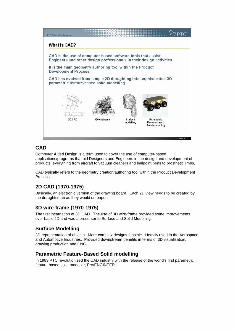
CAD Computer Aided Design is a term used to cover the use of computer-based applications/programs that aid Designers and Engineers in the design and development of products, everything from aircraft to vacuum cleaners and ballpoint pens to prosthetic limbs. CAD typically refers to the geometry creation/authoring tool within the Product Development Process.
2D CAD (1970-1975) Basically, an electronic version of the drawing board. Each 2D view needs to be created by the draughtsman as they would on paper.
3D wire-frame (1970-1975) The first incarnation of 3D CAD. The use of 3D wire-frame provided some improvements over basic 2D and was a precursor to Surface and Solid Modelling.
Surface Modelling 3D representation of objects. More complex designs feasible. Heavily used in the Aerospace and Automotive Industries. Provided downstream benefits in terms of 3D visualisation, drawing production and CNC
Parametric Feature-Based Solid modelling In 1989 PTC revolutionised the CAD industry with the release of the world’s first parametric feature based solid modeller, Pro/ENGINEER.

Solid Modelling Solid Modelling is the unambiguous representation of a component. Solid Models are virtual 3D representations of part that contain properties such as mass, volume, centre-of-gravity and surface area, and allow Engineers and Designers to accurately define every aspect of the component down to the smallest detail. Solid modelling also allows the Engineer to dynamically visualise the component from any angle and produce high quality outputs such as photo-realistic rendered images, animations (movies) and engineering production drawings. Solid Model components can be used in downstream applications like rapid prototyping and Computer Aided Manufacture.
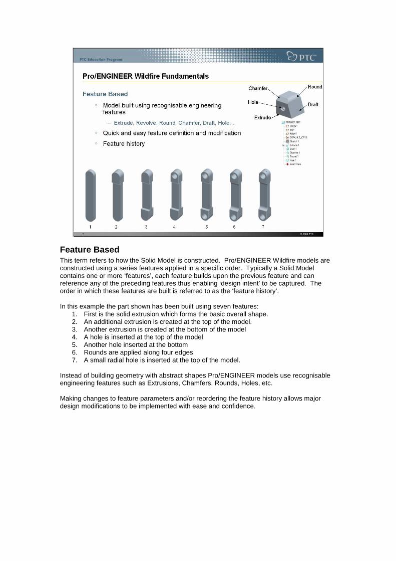
Feature Based This term refers to how the Solid Model is constructed. Pro/ENGINEER Wildfire models are constructed using a series features applied in a specific order. Typically a Solid Model contains one or more ‘features’, each feature builds upon the previous feature and can reference any of the preceding features thus enabling ‘design intent’ to be captured. The order in which these features are built is referred to as the ‘feature history’. In this example the part shown has been built using seven features:
1. First is the solid extrusion which forms the basic overall shape. 2. An additional extrusion is created at the top of the model. 3. Another extrusion is created at the bottom of the model 4. A hole is inserted at the top of the model 5. Another hole inserted at the bottom 6. Rounds are applied along four edges 7. A small radial hole is inserted at the top of the model.
Instead of building geometry with abstract shapes Pro/ENGINEER models use recognisable engineering features such as Extrusions, Chamfers, Rounds, Holes, etc. Making changes to feature parameters and/or reordering the feature history allows major design modifications to be implemented with ease and confidence.

The Extrude feature The Extrude feature is a sketch based feature and is probably the most commonly used feature within Solid Modelling. An Extrude features generates a 3 Dimensional object by giving a 2 Dimensional sketch depth. The Extrusion is always perpendicular to the 2D sketch. An Extrude feature can either add material or remove material.

The Revolve feature A Revolved feature is based on a sketch that is rotated about a centreline or a selected linear reference. The resulting solid can be dramatically changed by selecting a different rotation axis. A Revolve feature can either add or remove material.
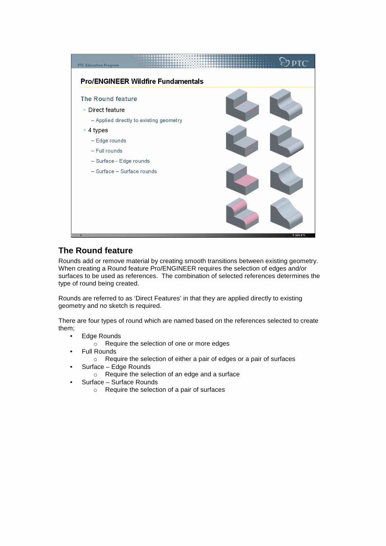
The Round feature Rounds add or remove material by creating smooth transitions between existing geometry. When creating a Round feature Pro/ENGINEER requires the selection of edges and/or surfaces to be used as references. The combination of selected references determines the type of round being created. Rounds are referred to as ‘Direct Features’ in that they are applied directly to existing geometry and no sketch is required. There are four types of round which are named based on the references selected to create them;
• Edge Rounds o Require the selection of one or more edges
• Full Rounds o Require the selection of either a pair of edges or a pair of surfaces
• Surface – Edge Rounds o Require the selection of an edge and a surface
• Surface – Surface Rounds o Require the selection of a pair of surfaces

The Chamfer feature Similar to Round features, Chamfers add or remove material by creating a bevelled surface between adjacent surfaces. Chamfers are referred to as ‘Direct Features’ in that they are applied directly to existing geometry and no sketch is required. There are several types of chamfer features, each defined by their dimensioning schemes. The most common Chamfers are;
• D x D – Size of Chamfer is defined by one dimension • D1 x D2 – Size of Chamfer is defined by two dimensions • ANG x D – Size of Chamfer defined by a linear dimension and an angle.
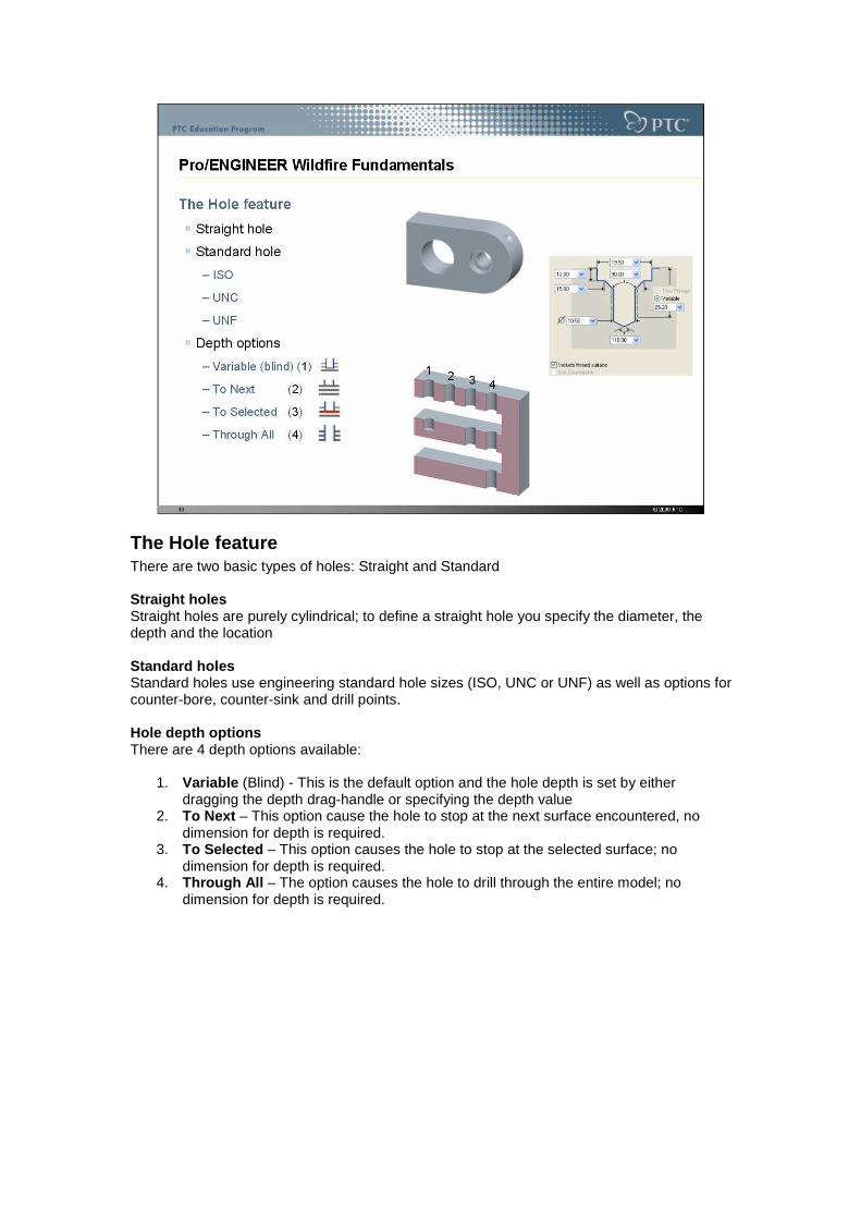
The Hole feature There are two basic types of holes: Straight and Standard Straight holes Straight holes are purely cylindrical; to define a straight hole you specify the diameter, the depth and the location Standard holes Standard holes use engineering standard hole sizes (ISO, UNC or UNF) as well as options for counter-bore, counter-sink and drill points. Hole depth options There are 4 depth options available:
1. Variable (Blind) - This is the default option and the hole depth is set by either dragging the depth drag-handle or specifying the depth value
2. To Next – This option cause the hole to stop at the next surface encountered, no dimension for depth is required.
3. To Selected – This option causes the hole to stop at the selected surface; no dimension for depth is required.
4. Through All – The option causes the hole to drill through the entire model; no dimension for depth is required.

Parametric The term “Parametric” means to be driven by parameters and their values. Each and every feature in Pro/ENGINEER is defined by a set of parameters, from simple sketch dimensions to feature variables (such as the radius of a round feature or the depth of an extrusion). If a change is made to one or more of these parameters the model will automatically update to reflect the new parameters and values. Pro/ENGINEER was the world’s first Parametric feature-based associative solid modeller.

Drawing Production Drawings are used to document and communicate product design information. They typically contain 2D orthographic and detailed views together with 3D views of the component and/or assembly, as well as dimensions, notes, and Bill of Materials. Production drawings have typically been a major part of the manufacturing process, however with today’s integrated CAD/CAM the solid model is used to directly drive Computer Numerically Controlled (CNC) machines/robots. Drawings are now being used to communicate critical dimensions and assembly process information.
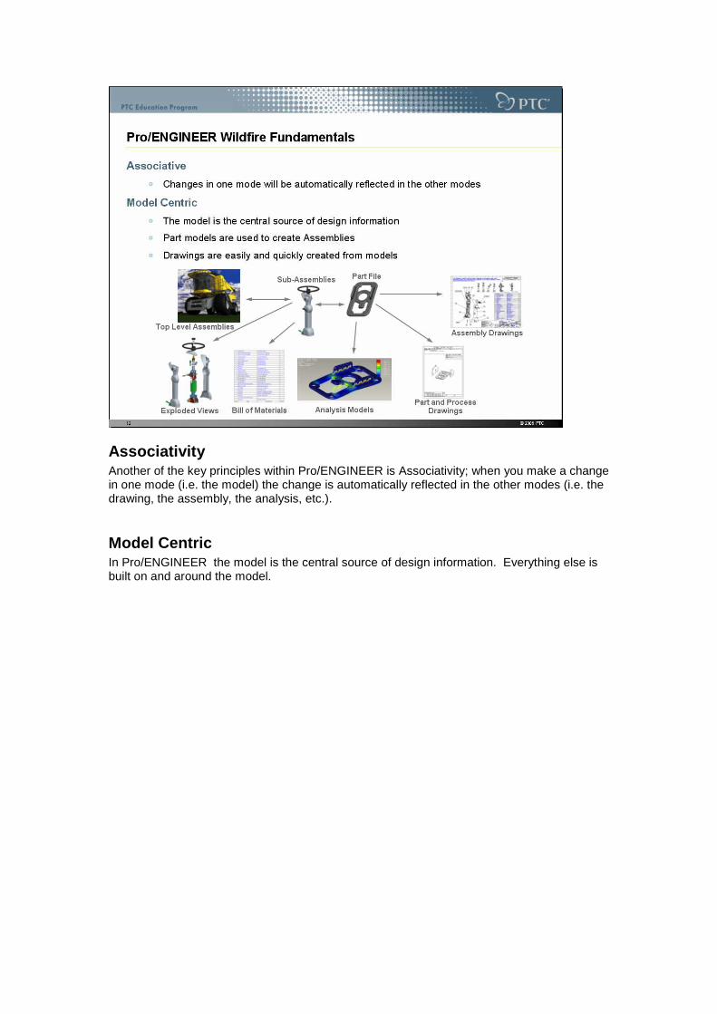
Associativity Another of the key principles within Pro/ENGINEER is Associativity; when you make a change in one mode (i.e. the model) the change is automatically reflected in the other modes (i.e. the drawing, the assembly, the analysis, etc.).
Model Centric In Pro/ENGINEER the model is the central source of design information. Everything else is built on and around the model.

Parent / Child relationships One of the most important concepts to understand within a parametric feature-based solid modelling system is that of Parent/Child relationships. The order in which features are created in the model builds up Parent/Child relationships. Why is this an important concept to understand? Changes to the Parent affect its Children. In the examples show here; the sketch is the Parent and the extrude feature the child. If the sketch is changed the resultant extrude feature will change accordingly. The same is true for the Round, in this case the edges are the Parents and Rounds are the children. Understanding how Parent/Child relationships are built up and the impact they have will allow Users to fully exploit the benefits of Pro/ENGINEER.

1.2 Pro/ENGINEER Wildfire 3.0 User Interface
Introduction Pro/ENGINEER Wildfire enables you to create design models within an intuitive, model-centric interface. You create and modify in the graphics window using Toolbars, Icons and the Dashboard. Equally important, the Pro/ENGINEER Wildfire interface includes the Navigator and Browser, which enable you to quickly locate, preview, and open design models. You also have the ability to manipulate and orient design models, which is an important and basic skill that you will use whenever you’re working in Pro/ENGINEER Wildfire.
Objectives After completing this section you will:
• Be able to navigate the Pro/ENGINEER Wildfire 3.0 User Interface • Understand how to interact with Pro/ENGINEER
o Using the Mouse and keyboard

Pro/ENGINEER Wildfire User Interface
Navigator The navigator is a pane with several tabs located on the left-hand side of the Pro/ENGINEER Wildfire interface. Folder Navigator : enables you to navigate the folders on your computer and network Favourites: enables you to bookmark Web pages and Folder locations (not shown in above image). Connections : provides links to common areas of interest for Pro/ENGINEER Users (not shown in above image). Model Tree : shown on the next slide.
Web Browser The Browser is an integrated content viewer within Pro/ENGINEER Wildfire. It works in conjunction with the Folder Navigator to help you find files on your computer as well as browse Web pages. In the above image the Web browser is divided into two sections; the File List and Preview Window. File List: When using the Folder Navigator, the browser displays files and models within the selected Folder. By using the File Type filter you can view specific Pro/ENGINEER Wildfire file types. Preview Window : when a Pro/ENGINEER Wildfire model is selected, a dynamic preview of the model appears in the browser. You can spin, Zoom and Pan the Preview to observe the model geometry. The Web Browser can also be used to browse the Internet on a computer with Internet access.
Main Menu Located at the top of the interface, the main menu contains standard commands and options such as File, Edit, and View.
Toolbars Toolbars contain icons for commonly used tools and functions: Main Toolbar – located along the top of the interface, contains common tools and view controls. Feature toolbar – located down the right if the interface, contains feature tools for creating models.
Message Window The message window provides you with prompts, feedback, and messages from Pro/ENGINEER Wildfire.
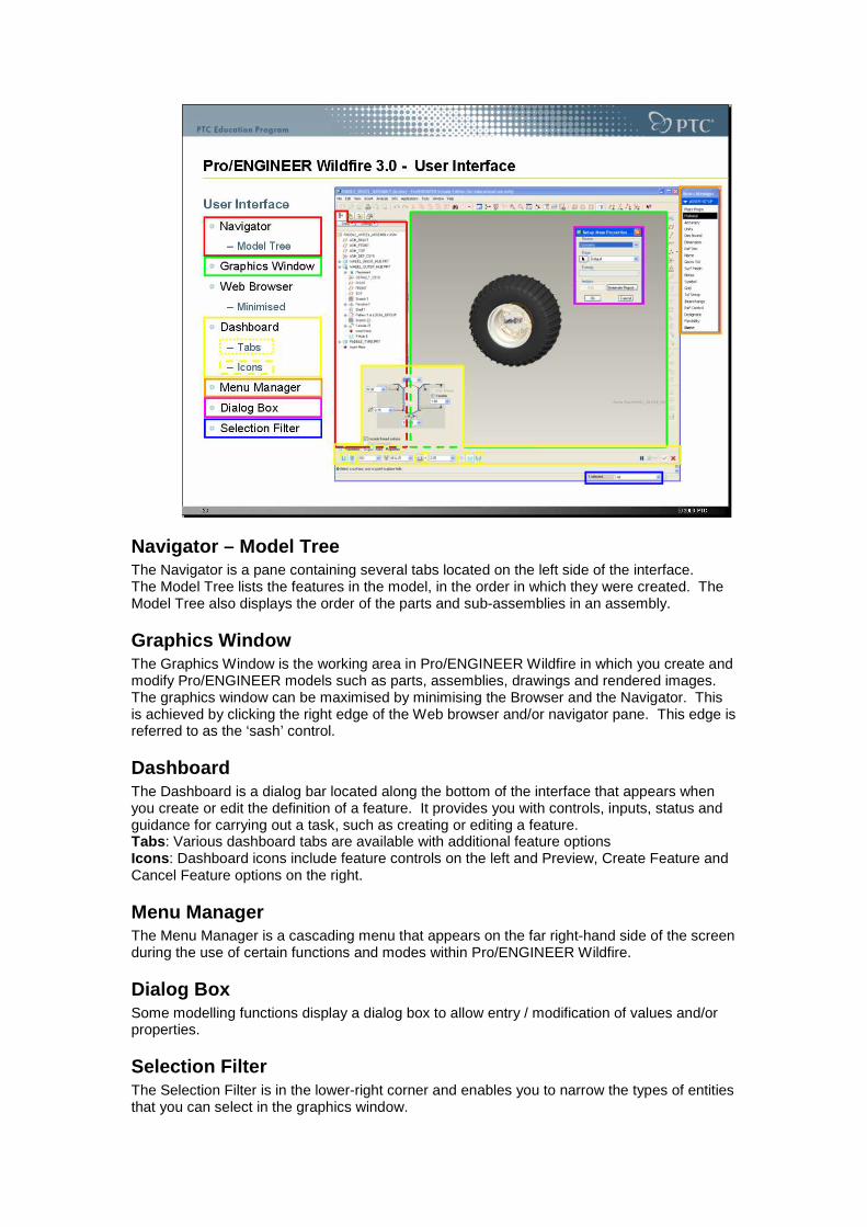
Navigator – Model Tree The Navigator is a pane containing several tabs located on the left side of the interface. The Model Tree lists the features in the model, in the order in which they were created. The Model Tree also displays the order of the parts and sub-assemblies in an assembly.
Graphics Window The Graphics Window is the working area in Pro/ENGINEER Wildfire in which you create and modify Pro/ENGINEER models such as parts, assemblies, drawings and rendered images. The graphics window can be maximised by minimising the Browser and the Navigator. This is achieved by clicking the right edge of the Web browser and/or navigator pane. This edge is referred to as the ‘sash’ control.
Dashboard The Dashboard is a dialog bar located along the bottom of the interface that appears when you create or edit the definition of a feature. It provides you with controls, inputs, status and guidance for carrying out a task, such as creating or editing a feature. Tabs : Various dashboard tabs are available with additional feature options Icons : Dashboard icons include feature controls on the left and Preview, Create Feature and Cancel Feature options on the right.
Menu Manager The Menu Manager is a cascading menu that appears on the far right-hand side of the screen during the use of certain functions and modes within Pro/ENGINEER Wildfire.
Dialog Box Some modelling functions display a dialog box to allow entry / modification of values and/or properties.
Selection Filter The Selection Filter is in the lower-right corner and enables you to narrow the types of entities that you can select in the graphics window.
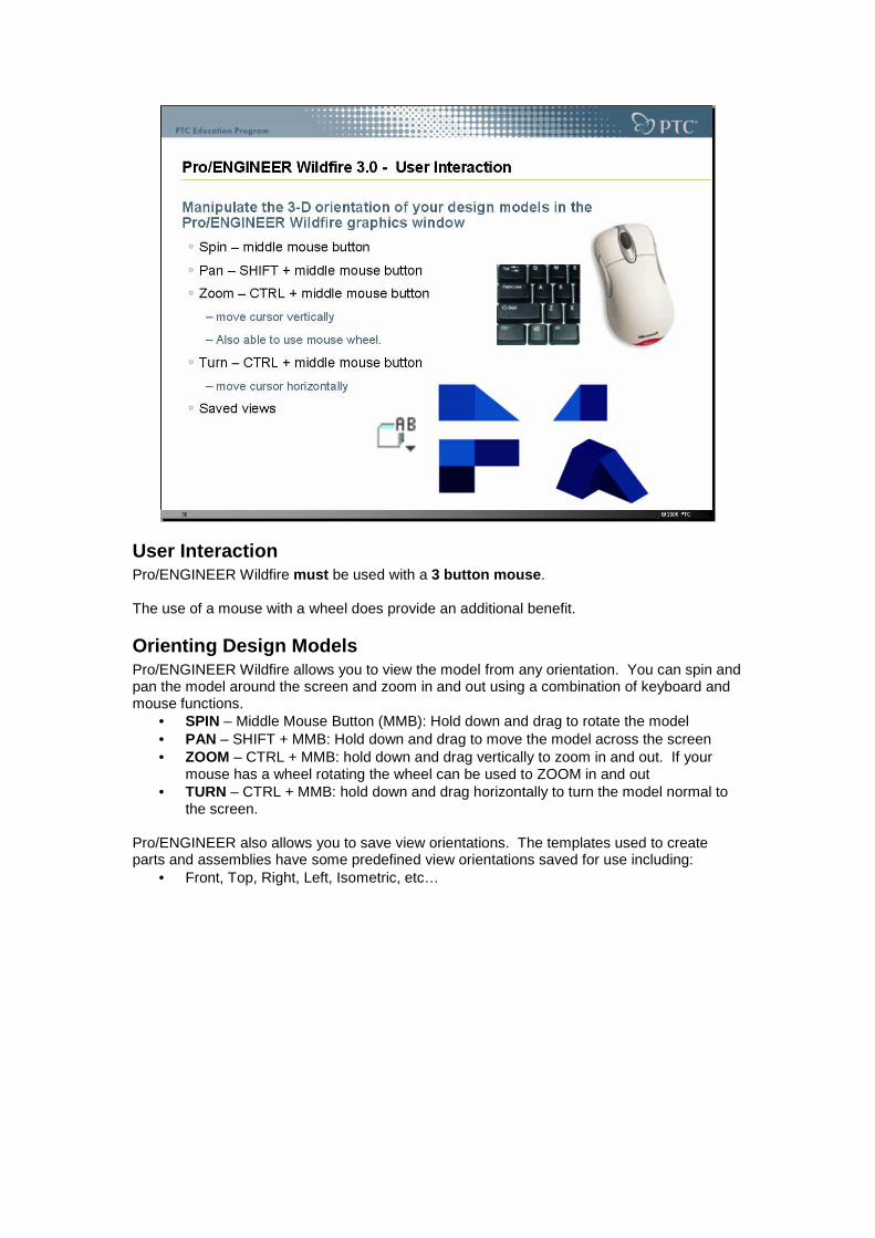
User Interaction Pro/ENGINEER Wildfire must be used with a 3 button mouse . The use of a mouse with a wheel does provide an additional benefit.
Orienting Design Models Pro/ENGINEER Wildfire allows you to view the model from any orientation. You can spin and pan the model around the screen and zoom in and out using a combination of keyboard and mouse functions.
• SPIN – Middle Mouse Button (MMB): Hold down and drag to rotate the model • PAN – SHIFT + MMB: Hold down and drag to move the model across the screen • ZOOM – CTRL + MMB: hold down and drag vertically to zoom in and out. If your
mouse has a wheel rotating the wheel can be used to ZOOM in and out • TURN – CTRL + MMB: hold down and drag horizontally to turn the model normal to
the screen. Pro/ENGINEER also allows you to save view orientations. The templates used to create parts and assemblies have some predefined view orientations saved for use including:
• Front, Top, Right, Left, Isometric, etc…

Selecting Geometry To select geometry within Pro/ENGINEER Wildfire simply move the cursor over the entity, Pro/ENGINEER will pre-highlight the geometry. To actually select the geometry press and release the left-hand mouse button, this action is known as “Left-Click” Pro/ENGINEER provides additional tools to help you select the required geometry, one such tool being the selection filter.

Multiple selection of geometry When more than one entity is to be selected the cursor is positioned over the additional entity and prior to selection the Ctrl key on the keyboard is held down. Select the additional entity/ies with Left-Click and when finished let go of the Cntrl key.

In Conclusion After completing this Module you should now be familiar with a number of the key concepts and terminology employed when using Pro/ENGINEER Wildfire. The subsequent training course will build on these concepts and provide you with the skills to create product designs within Pro/ENGINEER. This module complements the Pro/ENGINEER Quick Reference card which provides a easily navigated reference for User interaction with Pro/ENGINEER. The Quick Reference card can be downloaded at: http://www.ptc.com/community/proewf3/newtools/quick_reference.pdf

PTC’s Design & Technology in Schools Programme Over view PTC’s education programme provides teachers and professors with a complete and scalable learning solution to help prepare a new generation for success in a technology driven world. From secondary schools throughout to University level, PTC gives students the ultimate in engineering and product design education by providing software, training and classroom materials to educators around the world. PTC is proud to be part of a technological literacy movement that seeks to improve critical thinking and multi-dimensional problem solving skills. We’re share the passion and enjoyment of preparing a growing number of students to become engineers. PTC’s Educational Programmes help students;
• Build technological literacy • Learn to work collaboratively in teams • Develop communication, interpersonal and social skills • Improve critical and strategic thinking skills • Increase self confidence • Experience project-based problem solving • Become familiar with advanced design processes • Prepare for real-world careers in technology
The PTC Design & Technology in Schools Programme has been developed specifically for secondary schools. First launched in 1999, this programme has grown to become the number one Design education programme for middle and high schools around the world. Building on this experience PTC is expanding the programme to include its industry leading Pro/ENGINEER Wildfire Product Development System for both the classroom and student home use. PTC’s Design & Technology in Schools Programme also offers teacher training opportunities, classroom materials, discussion groups and web-based resources for design collaboration between schools. PTC’s commitment to education extends through to our University level programme which is the most comprehensive programme available to engineering professors and students worldwide.

Pro/ENGINEER Schools Edition Continuing PTC’s commitment to education, Pro/ENGINEER Schools Edition is made available to participating schools FREE of charge through the PTC Design & Technology in Schools Programme. The Schools Edition provides secondary schools students with the opportunity to use the same industry leading software used by colleges, Universities and professional engineers. The PTC Design & Technology programme uses both Pro/DESKTOP and Pro/ENGINEER Schools Edition as the FREE software for the programme. While Pro/DESKTOP provides a range of design and modelling functionality; Pro/ENGINEER provides significantly more depth allowing the creation of more complex and realistic designs. Capabilities & Benefits : FREE product offering to middle and high schools for classroom use and student home use (up to 300 seats per school) Easy to learn and use, with included multimedia tutorials, learning aids, project-based activities and classroom resource materials. Fully associative capabilities spanning modelling, assemblies, drawings, animations, kinematic analysis and design optimisation, renderings and much more.
Pro/ENGINEER Schools Advanced Edition This more advanced solution gives your students invaluable, hands-on experience to help prepare them for an engineering programme in college, university or for a job right out of high school. Providing the product design skills that a quarter million engineers currently employ will open many doors for students who decide to directly enter the workforce. Students who move on to University with Pro/ENGINEER Wildfire experience will also have a competitive advantage, as hundreds of leading Universities around the World currently use PTC software in the classroom. Pro/ENGINEER Wildfire is the most widely used 3D product design solution in world. Capabilities & Benefits: Several affordable package offerings Installation, registration and technical support via telephone or Internet Teacher training opportunities at PTC training facilities (on a space available basis) PTC produced training materials Software for student home use, allowing for additional exploration and learning outside of the classroom. For more information on PTC’s educational programmes please visit http://www.ptc.com/for/education/index.htm