te7210/lcd autodialer
TRANSCRIPT

TE7210/LCD AUTODIALER Integrated Full-Page Directory/ Autodialer
INTSTALLATION & PROGRAMMING MANUAL
Alpha Communiationswww.AlphaCommunications.com
42 Central Drive Farmingdale NY 11735Phone: 631-777-5500 (Toll Free: 800-666-4800)Fax: 631-777-5599 Email: [email protected]
AWD221Rev 1 (09/2016)

INSTALLATION MANUAL TE7210/LCD Auto-Dialer
SYSTEM DESCRIPTION
The TE7210/LCD is an integrated Electronic Directory and Auto-dialer in one panel. The benefits are simpler installation, less wiring and one programming effort for both directory and auto-dialer. Programming can be done locally (with a Lap-Top), or remotely (by a PC through RS-232 link). SYSTEM FEATURES
Full-page Directory, 20 lines per page
One-Effort Programming on a Windows PC via RS-232 port (DB9) or USBadaptor
700 name capacity
26 characters per name field, 4 digits per code and 12 digits per phone number
Tenant codes can be actual suite numbers or coded for security
Variable Tenant Code length 1,2,3 or 4 digits
4, 7, 10 and 11 digit dialing capability.
26 point font size, Upper and Lower case.
Sorting by name or code
Customized welcome message
Zinc Die-Cast Marine Quality user Keypad
Non-Volatile Memory; retains programmed information during total power failure
Superior Lightning and Transient protection
2 Programmable Relay outputs to control door strikes, gates, cameras, etc.
Built-in Multiple Entrance capability
Tone and Tapping Rejection circuitry to prevent Unauthorized Entry.
Provision for Postal Service Lock included
Switch input to Pulse entry doors during Emergency (Fire Alarm)
Door-Timer Cutoff sensor input prevents ‘Tail Gating” through entry doors
Keyless Entry Codes
Voice mail (Active Keypad) capability
Interface to Card Access System (Wiegand 26 bits)
Phone system Auto Dialer or No Phone Line Lobby Panel
INSTALLATION MANUAL TE7210/LCD Auto-Dialer
TABLE OF CONTENTS
1.0 PREPARATION 1.1 Site Preparation………………………………………………………………1 1.2 Powering the system…………………………………………………………1
2.0 SPECIAL FEATURES 2.1 Postal Service Lock…………………………………………………………2 2.2 Door Timer Cutoff...…………………………………………………………2 2.3 Auxiliary Relay ………………………………………………………………2 2.4 Emergency Input…………………………………………………………….2 2.5 Multiple Entrances…………………………………………………………..2 2.6 Wiegand Card Access Interface…………………………………..…….…2
3.0 INSTALLATION 3.1 Mounting the unit…………………………………………………………….3 3.2 Wiring………………………………………………………………………….5
4.0 CONNECTION TO PC 4.1 Local Lap-top…………………………………………………………………8 4.2 Remote Computer……………………………………………………………8
5.0 SYSTEM PROGRAMMING 5.1 Entering Data for Autodialer…………………………………………………9 5.2 Entering Data for No-Phone-Line system………………………………….9 5.3 Sorting Data…………………………………………………………………..11 5.4 Building Database Files (Multiple buildings)………………………………12 5.5 Communicating to Autodialer Unit ………………………………………...12
6.0 SYSTEM OPERATION………………………………………………………….…...13
APPENDICES
A. Regulation Approvals & System Warranty B. System Wiring Diagram C. Weigand Card Access Interface D. User Instruction Sheet

INSTALLATION MANUAL TE7210/LCD Auto-Dialer
1.0 PREPARATION:
1.1 Site Preparation: The unit will be installed at the building entrance. Consider a proper location with good visibility and accessibility for the users
Arrange with the phone company to install a telephone line to be used bythe unit. It is recommended a jack be installed inside the entry panelenclosure.
If the unit is to be used with No-Phone-Line intercom system, consider aproper location for tenant wiring distribution equipment.
1.2: Powering the System: One UL/CSA approved 16VAC-40VA Class 2 transformer is required for the unit operation.
Another Class 2 transformer is required for the door strike. This transformer should have the voltage and current rating specified for the door strike. However, do not exceed the maximum door relay rating of 3 Amp @ 28 VDC.
Transformers and remote devices, such as door strikes, emergency contacts, door sensors etc. must be wired to the terminal blocks inside the unit. A wiring channel must be provided from these devices to the back of the unit enclosure; follow local building code requirements for low-voltage wiring.
1

INSTALLATION MANUAL TE7210/LCD Auto-Dialer
2.0 SPECIAL FEATURES:
2.1 Postal Service Lock: Provision for installation of a Postal Service Lock is available inside of the unit. The unit is pre-wired for this service,
2.2 Door Timer Cutoff: This feature requires installation of a Normally Open Sensor on the entrance door. This sensor should close when the door is open. A Normally Open Magnetic sensor, used in security systems, is acceptable for this application.
Usually, the entrance door strike is released for the programmed door time (see section 5.1). This feature terminates the door time when the door is sensed closed after the visitor enters. It prevents unauthorized entry of other individuals who follow the visitor (tailgating).
2.3 Auxiliary Relay: The system includes a Form C relay contact. It is momentarily activated by dialing digit 6, from the suite, during the tenant conversation with visitor. It can be used to trigger Parking Gate, Elevator, a second Door, or a Video Camera. Dialing digit 6 needs to be done prior to dialing 9 for opening the entrance door.
2.4 Emergency Input Contact: Closing this normally-open contact will cause the electric door strike be pulsed ON and OFF. This will effectively leave the door unlocked for the duration of the closed contact (Emergency).
2.5 Multiple Entrances: Up to 20 entry systems can be connected to one common telephone line. The only extra requirement is a pair of wires connected in parallel (daisy chain) to terminals ME and G of all units.
These common wires temporarily disable the other units, when one is being used. “System in Use” messages are displayed on all disabled units. Note, that all these units must be independently powered and programmed. They also require telephone extension jacks (for the common line) installed at their own locations.
2.6 Wiegand Interface: This is a built-in feature. Standard 26 bit protocol. 3 wire interface and no programming required at our panel. Refer to appendix C for details.
2

INSTALLATION MANUAL TE7210/LCD Auto-Dialer
3.0 INSTALLATION:
Installation, of the unit, consists of 2 steps; mounting it at the building entrance and its wiring.
3.1 Mounting the Unit:
Mount the unit to the wall, close to the building’s controlled entrance door: Two methods are used:
Surface Mount:
This is for mounting the unit on the wall surface. Open the unit front and note the 4 holes for mounting screws.
Carefully mark these holes on the wall, at an appropriate height from floor for easy access. Drill and install plastic inserts (if required). Then, using four self-tapping or wood screws, secure the unit to the wall.
3

INSTALLATION MANUAL TE7210/LCD Auto-Dialer
Flush Mount:
In this method, the unit is installed inside the wall so that its front face is semi flush with the wall. This is done by first cutting an opening in the wall and installing the 7210/TR Trim Ring as the panel mounting bezel.
Carefully inspect the Trim Ring to plan the wall opening. The opening should be19 5/8”x 13 5/8” and 2 ¼” deep so that the trim ring fits properly.
Use a drywall saw cut this opening. Then, attach wood supports behind the wall surface, just under the lower edge and above the upper edge of the opening. Attach these supports firmly to the wall frame (with nails, glue, screws, etc.). The Trim ring can now be pushed into the opening and secured to these wood supports by four wood screws through the 4 holes of trim’s upper and lower lips.
If the wall has a sound internal opposite surface, at 2 ¼ depth, the trim ring can be attached to it through holes of its left and right inside lips (the 4 holes without tapping). This can be use as the main mounting method or in addition to the method described above (for extra strength).
Follow the above method for other wall materials; such as Brick, Cement, Tiles, Marble, etc.
Finally, once the trim ring is mounted properly, install the DoorChek panel inside it. Secure the four 8-32 screws through the Panel’s four corner holes.
The exploded view of the installation, as well as its cross sectional view, is presented in the above picture.
4

INSTALLATION MANUAL TE7210/LCD Auto-Dialer
3.2 Wiring:
Refer to wiring diagram in appendix B. Keep the enclosure door open for wiring.
1. Entry Door Strike: Four methods are possible:A. Normally Open Contact: Connect the Door Strike and Power Supply, in
series, across terminals T4 and D4 (as shown below). Use DC power supply for Silent strike or AC power supply (transformer) for Buzzing strike.
B. DC Silent: Connect the strike across D1 and D2 terminals and use a Class 2 transformer; connecting to terminals T3 and T4 (as shown below). This method utilizes unit’s internal rectifier to provide silent operation using an AC transformer.
5
INSTALLATION MANUAL TE7210/LCD Auto-Dialer
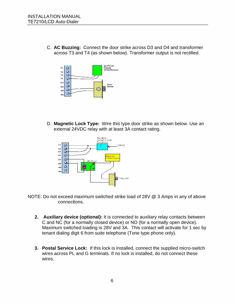
C. AC Buzzing: Connect the door strike across D3 and D4 and transformer across T3 and T4 (as shown below). Transformer output is not rectified.
D. Magnetic Lock Type: Wire this type door strike as shown below. Use an external 24VDC relay with at least 3A contact rating.
NOTE: Do not exceed maximum switched strike load of 28V @ 3 Amps in any of above connections.
2. Auxiliary device (optional): It is connected to auxiliary relay contacts betweenC and NC (for a normally closed device) or NO (for a normally open device). Maximum switched loading is 28V and 3A. This contact will activate for 1 sec by tenant dialing digit 6 from suite telephone (Tone type phone only).
3. Postal Service Lock: If this lock is installed, connect the supplied micro-switchwires across PL and G terminals. If no lock is installed, do not connect thesewires.
6

INSTALLATION MANUAL TE7210/LCD Auto-Dialer
4. Door Timer Cutoff (Tailgating) sensor: connect across terminals TC and G.This should be a Normally Open sensor which closes when the door is open.When door is opened, the door timer will be terminated and instantly de-energizethe door strike (lock the door).
5. Emergency Contact: is connected across FA and G terminals. This should be anormally open contact. When it closes, it causes door strike to be pulsed (toavoid overheating) and door will be unlocked.
6. Common Wires for Multiple Entry system: Connect across terminals ME andG of all units. These common wires allow operation of multiple units with acommon phone line (disabling all but the unit in use). The unit at each location,however, must be wired to its own power transformer, door strike, extensionphone jack, switching contacts, etc. ( as shown on the wiring diagram). Eachlocation must also be separately programmed.
7. At this time, all above wiring should be checked for correctness, shortsand opens: If all pass, connect 16VAC from main power transformer toterminals T1 and T2.This transformer should not be used to power other device such as door strikes,cameras, etc. These devices require their own separate power supplies.
8. For Card Access interface (Weigand 26 bit), please refer to Appendix C.
Move the Power Switch to ON position. LEDs on Both Dialer and Directory should light up. The Display will be illuminated and the Welcome message will appear.
The Telephone Line may be connected now.
NOTES:
After powering the unit, the factory Welcome Message will be displayed. At thisstage there is no programmed data. Connect the unit to a PC (see section 4) toprogram.
We recommend turning Power switch OFF prior to PC connection. Otherwise, itmay cause the unit or your PC to malfunction. If this occurs, resetting the powerwill restore operation.
The system is now ready for normal operation. The user presses the Up/Downkeys to move to the next or the previous page. The Welcome message will bereplaced by the first page of the programmed name list, The welcome messagewill return automatically if no key is pressed for one minute
7

INSTALLATION MANUAL TE7210/LCD Auto-Dialer
4.0 PC CONNECTION
A PC with windows operating system is required for programming. This can be a local lap-top computer brought to the installation site or a remote computer communicating from building management / guard office. Communication between PC and Directory takes place at 2400 baud which translates to approximately 300 names per minutes Upload or Download.
4.1 Local Lap-Top PC: A lap-top, brought to the installation site, is used to program the unit. This has the advantage of visual confirmation of the results on the unit LCD display.
If your lap-top has an RS-232 port, just connect it to the DB-9connector, of the Directory board, with a M/F extension (straightthrough) DB9 cord.
If your PC has a USB port, connect its USB port to unit’s DB9connector with a USB to Serial Conversion cable. We recommendNexxtech conversion cord available from the Source.
4.2 Remote PC: The 3-wire PC communication terminal block (on directory board) is wired to the remote computer site (up to 1000 ft). It is then connected to Remote computer serial port (RS-232) directly or to a USB port (with a USB to Serial Converter cable).
On the PC side, connect the 3-wire (from the terminal block) to the 9-pin serial port (or the Serial-USB converter) use the 3 to 9-pin conversion link provided (shown on the diagram below).
8

INSTALLATION MANUAL DoorChek Directory Auto-Dialer
5.0 SYSTEM PROGRAMMING
After connection to the PC, you need to run the provided DoorChek Management software. The advantages of using a PC for programming are:
Convenience: Entering names, codes and phone numbers as well as thewelcome message is done from the convenience of your office.
Maintaining a back up: A copy of the programmed information could (andshould) always be kept. A quick functional restoration can be done in the eventof user error or equipment failure.
Installation of the Software: You can obtain the latest version of this software from our website: http://interco.ms/part/te7210/lcd
To install the software, open the zip file then click on the ‘Install’ Icon on the screen. ‘DoorChek’ icon will be created on your desktop.
Running the Software: Click on the ‘DoorChek’ Icon, then click the continue button. The Main window opens.
The software is menu driven, self explanatory and user friendly. From the ‘File’ menu, open a new or existing file then follow the graphic Icons and help instructions.
The main tasks are as follows:
5.1 Entering Data for Autodialer:
To add Tenants: Click on ‘Add Resident’, type the name, code and phonenumber in boxes provided. Press ‘enter (or ‘next’) for next. When list is done,click ‘Finish’.
To Edit a Tenant, Click on the Edit Resident Icon and modify the data for a tenantby typing over the older data then click Finish.
Remove a Resident: Click on ‘Remove Resident’ Icon, move the curser to thedesired tenant and click on the red X at the bottom then click Finish.
To Delete all residents, click on ‘Remove all’ icon. To Create or Edit the Welcome screen, click on the ‘Edit Welcome’ icon and type
(or modify) the text then click Finish. To Enter or Modify Talk Time or Door Time, click on the ‘Set timers’ icon, enter
the data then click Finish.
9

INSTALLATION MANUAL TE7210/LCD Auto-Dialer
Add Resident Screen
Note 1: Phone numbers should be entered in 7, 10 or 11 (Long Distance) digits. Note 2: Codes are 1, 2, 3 or 4 digits. Note 3: Relay # (NPL System) can be entered in 4 digits (see next section 5.2).
10

INSTALLATION MANUAL TE7210/LCD Auto-Dialer
Set Timers Screen
5.2 Entering data for No-Phone-Line system:
It is done as above, with the exception of the phone number field format: Relay code format is 4 digits; 1st Relay is 0000, 2nd 0001 …..etc Off-premise phone number (or cell phone) format is digit 9 followed by the 10-
digit phone number.
Note: Long-Distance numbers are presently not supported for No-Phone-Line system,
5.3 Sorting Data:
The Directory tenant display needs sorting for quick and easy resident location. To Sort the names, click on ‘Sort by Name’ or ‘Sort by Code’ then click Finish.
Data should always be sorted after editing, entry or deleting.
REMEMBER: make sure you save the changes before exiting.
11

INSTALLATION MANUAL TE7210/LCD Auto-Dialer
5.4 Building Database Files (Multiple Buildings):
Each building’s Resident data, Welcome message and Talk / Door times are saved in a file. This way, each building has its own database. We recommend to name the file after the building.
To see or modify a particular building database file, you can open it by clicking the ‘open’ button on the top or use the Windows File menu.
5.5 Communication to AutoDialer Unit:
To send (download) the edited database, to the DoorChek Autodialer, make sure you have connected the PC to the unit (as described in section 4) then click ‘Send’ icon.
To upload data, from the DoorChek Autodialer , click the ‘Receive’ icon.
Remember to select the proper Serial port number of the PC (you are connected it) when the ‘send’ or ‘receive’ windows open for the first time. This port number will be remembered.
Note: For multiple buildings, which are connected to different COM Ports, you need to select the proper COM port number each time you communicate with a different building.
12

INSTALLATION MANUAL TE7210/LCD Auto-Dialer
6.0 SYSTEM OPERATION:
From User’s point of view, the operation of the system is very simple.
Press the large Up or Down keys until the page with the desired name appears Enter the corresponding code on the keypad The system automatically dials the resident and a dialog starts The resident may open the door (by dialing 9) and let the visitor in, or hang up to
deny entry The system goes back to welcome screen display after 1 minute automatically The resident may activate the auxiliary device (Camera, Parking gate, Elevator,
etc) by dialing 6. This should be done prior to dialing 9 to open the door.
13

INSTALLATION MANUAL TE7210/LCD Auto-Dialer
APPENDIX A REGULATORY APPROVALS
IMPORTANT NOTICE
The following information is provided to the installation contractor for compliance with Industry Canada Standards.
NOTICE: The Industry Canada label identifies certified equipment. This certification means that the equipment meets certain telecommunications network protective, operational and safety requirements. Industry Canada does not guarantee that the equipment will operate to the user’s satisfaction.
Before installing this equipment, users should ensure that it is permissible to be connected to the facilities of the local telecommunications company. The equipment must also be installed using an acceptable method of connection. The customer should be aware that compliance with the above conditions may not prevent degradation of service in some situations.
Repairs to certified equipment should be made by an authorized Canadian maintenance facility designated by the supplier. Any repairs or alterations made by the user to this equipment, or equipment malfunctions, may give the telecommunications company cause to request the user to disconnect the equipment.
Users should ensure for their own protection that the electrical ground connections of the power utility, telephone lines and internal metallic water pipe system, if present, are connected together. This precaution may be particularly important in rural areas.
CAUTION: Users should not attempt to make such connections themselves, but should contact the appropriate electric inspection authority, or electrician, as appropriate.
The Load Number (LN) assigned to each terminal device denotes the percentage of the total load to be connected to a telephone loop which is used by the device, to prevent overloading. The termination on a loop may consist of any combination of devices subject only to the requirement that the sum of the Load Numbers of all devices does not exceed 100.
The Load Number for this Equipment is 4.0 Industry Canada Certification No.: 1949 5264 A
SYSTEM WARRANTY
Equipment is warranted to be free of defects in material and workmanship for a period of one (1) year from the original shipment date. Alpha Communications will, at its option, repair or replace any equipment which it determines to be defective in material or workmanship. Equipment thought to be defective is to be shipped freight prepaid to Alpha Communications; Alpha Communications will prepay return freight. Alpha Communications shall not be responsible to repair or replace equipment which has been abused, incorrectly installed, repaired by others, altered or otherwise misused or damaged in any way. Unless previously contracted by Alpha Communications, Alpha Communications will not assume responsibility for determining the defective or operative status at the point of installation, and will not assume liability beyond the repair or replacement of the product at our factory or authorized service centre.

INSTALLATION MANUAL TE7210/LCD Auto-Dialer
INSTRUCTION TO THE U.S. USER FCC REQUIRED INFORMATION
FCC REGULATIONS
This device has been granted a registration number by the FCC, under part 68 rules and regulations governing devices that directly connect to the telephone lines. This equipment complies with Part 68 of the FCC rules. A label on the controller housing of the TE7210/LCD contains, among other information, the FCC Registration Number and Ringer Equivalence Number (REN) for this equipment. You must, upon request, provide this information to your telephone company.
The REN is useful to determine the quantity of devices that you may connect to your telephone line and still have those entire devices ring when your telephone number is called. In most, but not all areas, the sum of the REN's of all devices connected to one line should not exceed five (5.0). To be certain of the number of devices that you may connect to your line, you may want to contact your telephone company to determine the maximum REN for your calling area.
This equipment may not be used on coin service provided by the telephone company. Connection to party lines is subject to state tariffs.
Should the TE7210/LCD cause harm to the telephone network, the telephone company may discontinue your service temporarily. If possible, they will notify you in advance. But if advanced notice is not practical, you will be notified as soon as possible. You will be informed of your right to file a complaint with the FCC. The telephone company may make changes in its facilities, equipment, operations or procedures that could affect the proper functioning of your equipment. If they do, you will be notified in advance to give you an opportunity to maintain uninterrupted telephone service.
If you experience trouble with this equipment, please contact:
Alpha Communicationswww.AlphaCommunications.com42 Central Drive Farmingdale NY 11735P: 631-777-5500 F: 631-777-5599
for information to obtain service or repairs. The telephone company may ask that you disconnect this equipment from the network until the problem has been corrected or until you are sure the equipment is not malfunctioning.

Appendix C
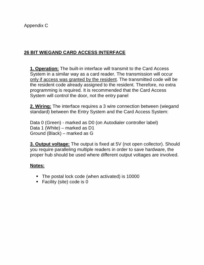
26 BIT WIEGAND CARD ACCESS INTERFACE
1. Operation: The built-in interface will transmit to the Card AccessSystem in a similar way as a card reader. The transmission will occur only if access was granted by the resident. The transmitted code will be the resident code already assigned to the resident. Therefore, no extra programming is required. It is recommended that the Card Access System will control the door, not the entry panel
2. Wiring: The interface requires a 3 wire connection between (wiegandstandard) between the Entry System and the Card Access System:
Data 0 (Green) - marked as D0 (on Autodialer controller label) Data 1 (White) – marked as D1 Ground (Black) – marked as G
3. Output voltage: The output is fixed at 5V (not open collector). Shouldyou require paralleling multiple readers in order to save hardware, the proper hub should be used where different output voltages are involved.
Notes:
The postal lock code (when activated) is 10000 Facility (site) code is 0

TE7210/LCD
USER OPERATING INSTRUCTIONS
A TE7210/LCD Intercom System has been installed in your building to provide increased security for you and your visitors. The system provides communication and entry control using your telephone.
Visitors simply enter your code number from the directory to ring your suite. You can answer from any telephone.
To permit entry, dial the digit "9".
To deny entry, simply hang-up. Do not dial "9".