tappingmode imaging is implemented in ambient air (or liquid) by oscillating the cantilever assembly...
TRANSCRIPT

TappingMode imaging is implemented in ambient air (or liquid) by oscillating the cantilever assembly at or near the cantilever’s resonant frequency using a piezoelectric crystal. The piezo motion causes the cantilever to oscillate with a high amplitude (the “free air” amplitude, typically greater than 20nm) when the tip is not in contact with the surface. The oscillating tip is then moved toward the surface until it begins to lightly touch, or “tap” the surface. During scanning, the vertically oscillating tip alternately contacts the surface and lifts off, generally at a frequency of 50,000 to 500,000 cycles per second. As the oscillating cantilever begins to intermittently contact the surface, the cantilever oscillation is necessarily reduced due to energy loss caused by the tip contacting the surface. The reduction in oscillation amplitude is used to identify and measure surface features.
TAPPINGMODE™ IMAGING
APPLICATIONS AND TECHNOLOGY

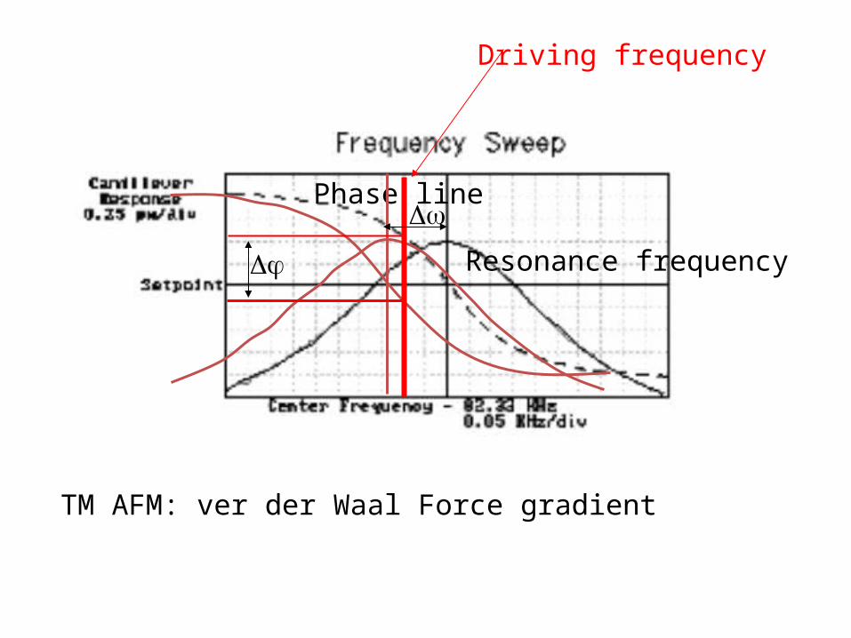
TM AFM: Constant Force Gradient: taking advantage of the vibrational characteristics of the cantilever

V piezo = Vac sin(t+ 1)
A piezo = Aac sin(t+ 1)
Applied electronic Signal to the Piezo
Produced a sine wave oscillation with the same frequency and phase angle
ACantilever = Acantilever sin(t+ 1)
Resonant

Tapping cantilever on free air
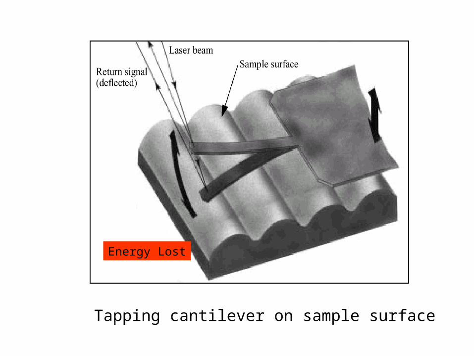
Tapping cantilever on sample surface
Energy Lost

TappingMode Cantilever oscillation amplitude in free air and during scanning.
ACantilever = Acantilever sin(1t+ 1)
ACantilever(scanning) = Acantilever(Scanning) sin(2t+ 2)
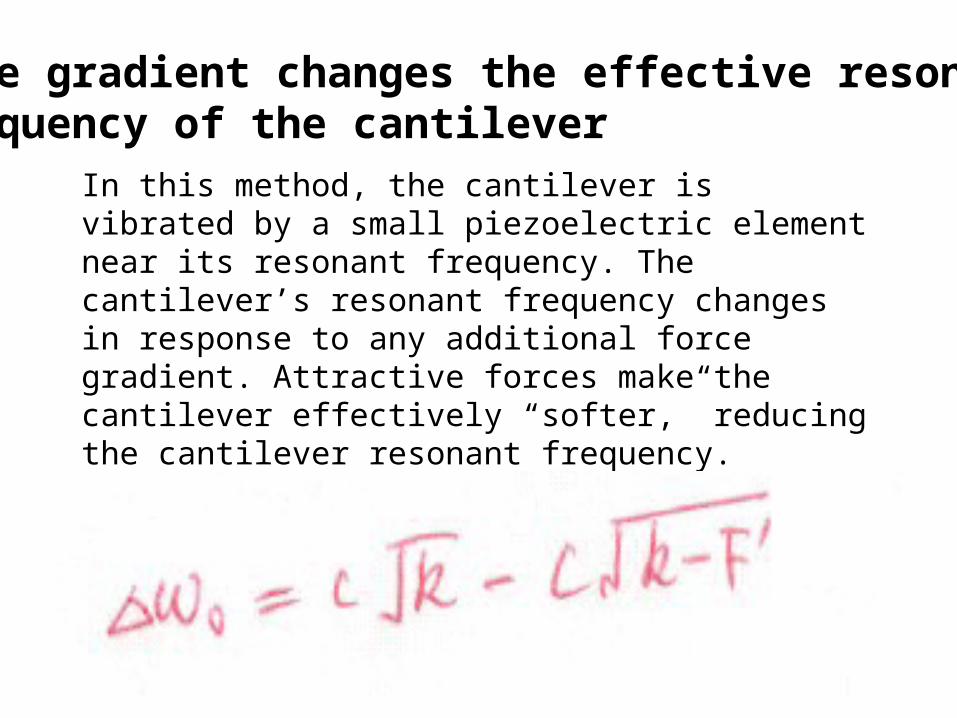
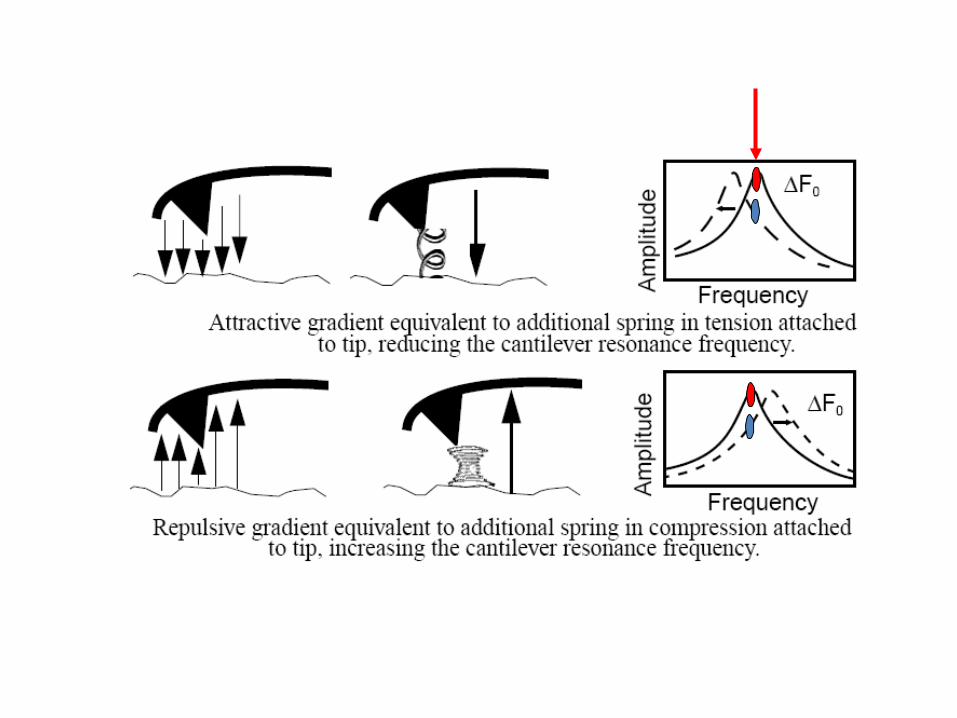
In this method, the cantilever is vibrated by a small piezoelectric element near its resonant frequency. The cantilever’s resonant frequency changes in response to any additional force gradient. Attractive forces make the cantilever effectively “softer,” reducing the cantilever resonant frequency. Conversely, repulsive forces make the cantilever effectively “stiffer,” increasing the resonant frequency.
Force gradient changes the effective resonance frequency of the cantilever


Force gradient changes the vibrational amplitude at the driving frequency of the cantilever
A (xy) is a function ofPosition on the sample.

Resonance frequency
Phase lineA
Driving frequency
TM AFM: ver der Waal Force gradient
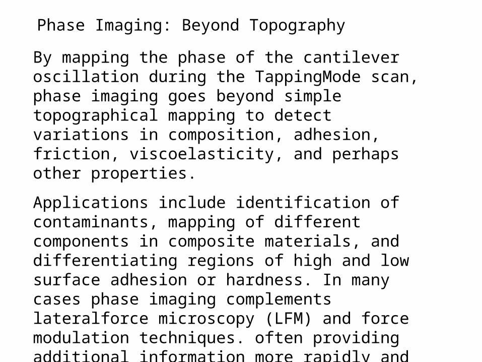
By mapping the phase of the cantilever oscillation during the TappingMode scan, phase imaging goes beyond simple topographical mapping to detect variations in composition, adhesion, friction, viscoelasticity, and perhaps other properties.
Applications include identification of contaminants, mapping of different components in composite materials, and differentiating regions of high and low surface adhesion or hardness. In many cases phase imaging complements lateralforce microscopy (LFM) and force modulation techniques. often providing additional information more rapidly and with higher resolution. Phase imaging is as fast and easy to use as TappingMode AFM — with all its benefits for imaging soft, adhesive, easily damaged or loosely bound samples
Phase Imaging: Beyond Topography
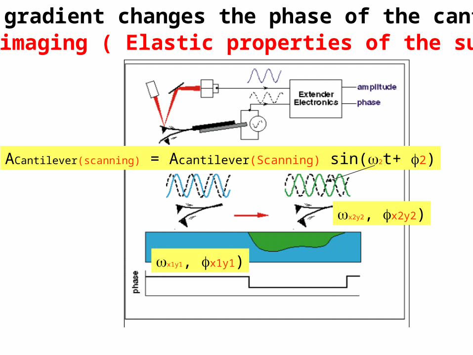
ACantilever(scanning) = Acantilever(Scanning) sin(2t+ 2)
x1y1, x1y1)
x2y2, x2y2)
Phase imaging ( Elastic properties of the surface)Force gradient changes the phase of the cantilever
Resonance frequency
Phase line
Driving frequency
TM AFM: ver der Waal Force gradient

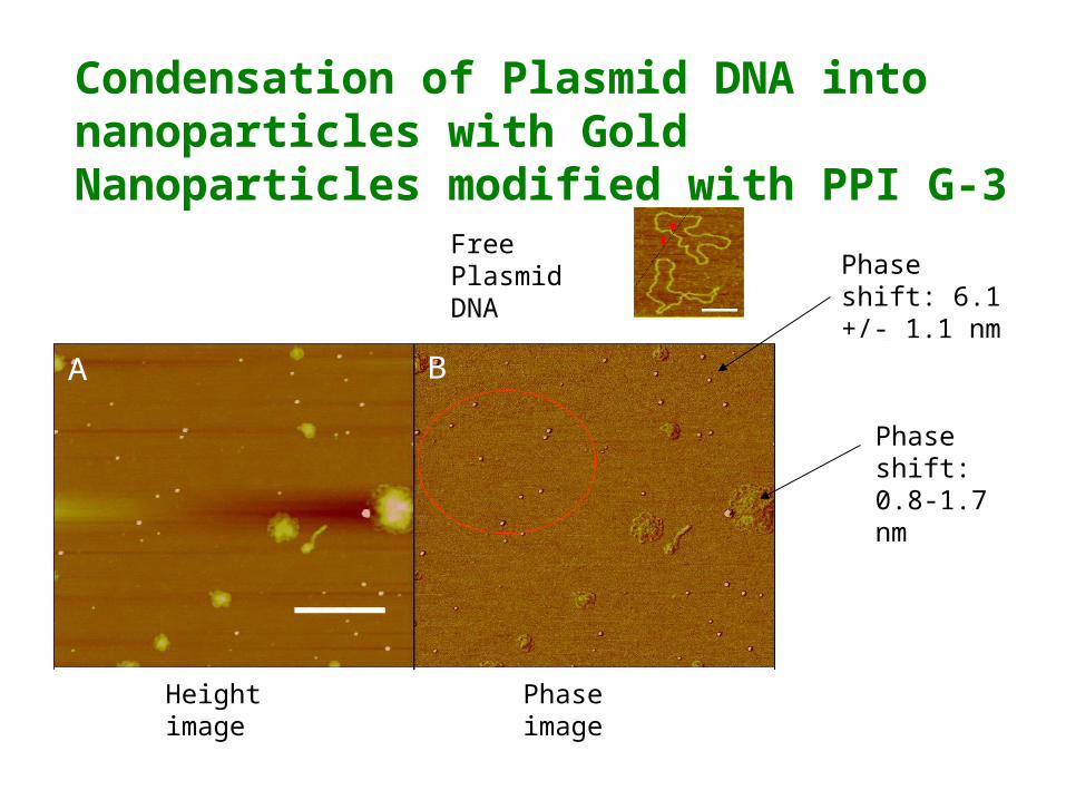
Free Plasmid DNA
A BA B
Height image Phase image
Condensation of Plasmid DNA into nanoparticles with Gold Nanoparticles modified with PPI G-3
Phase shift: 6.1 +/- 1.1 nm
Phase shift: 0.8-1.7 nm

Summary
In TappingMode AFM, the cantilever is excited into resonance oscillation with a piezoelectric driver. The oscillation amplitude is used as a feedback signal to measure topographic variations of the sample. In phase imaging, the phase lag of the cantilever oscillation, relative to the signal sent to the cantilever’s piezo driver, is simultaneously monitored. The phase lag is very sensitive to variations in material properties such as adhesion and viscoelasticity.

Need Imaging in Fluid to Enhance Resolution or In-situ
Monitoring Biological or Chemical Processes


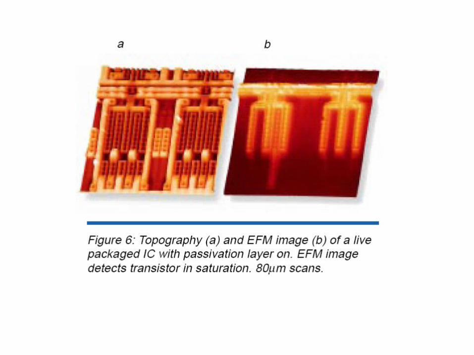
Electric Force Microscopy (EFM)
EFM is used to map the vertical (z) and near-vertical gradient of the electric field between the tip and the sample versus the in-plane coordinates x and y. This is done using LiftModeTM. The field due to trapped charges—on or beneath the sample surface—is often sufficiently large to generate contrast in an EFM image. Otherwise, a field can be induced by applying a voltage between the tip and the sample. The voltage may be applied directly from the microscope’s electronics under AFM software control, or from an external power supply with appropriate current-limiting elements in place. EFM is performed in one of three modes:
amplitude detection, phase detection, or frequency modulation (FM).

Electrostatic Interactions is long range interaction

EFM/MFM
Conductive Domains
Magnetic tip, instead of only a conductive tip
Piezoelectric materials

In this method, the cantilever is vibrated by a small piezoelectric element near its resonant frequency. The cantilever’s resonant frequency changes in response to any additional force gradient. Attractive forces make the cantilever effectively “softer,” reducing the cantilever resonant frequency. Conversely, repulsive forces make the cantilever effectively “stiffer,” increasing the resonant frequency.
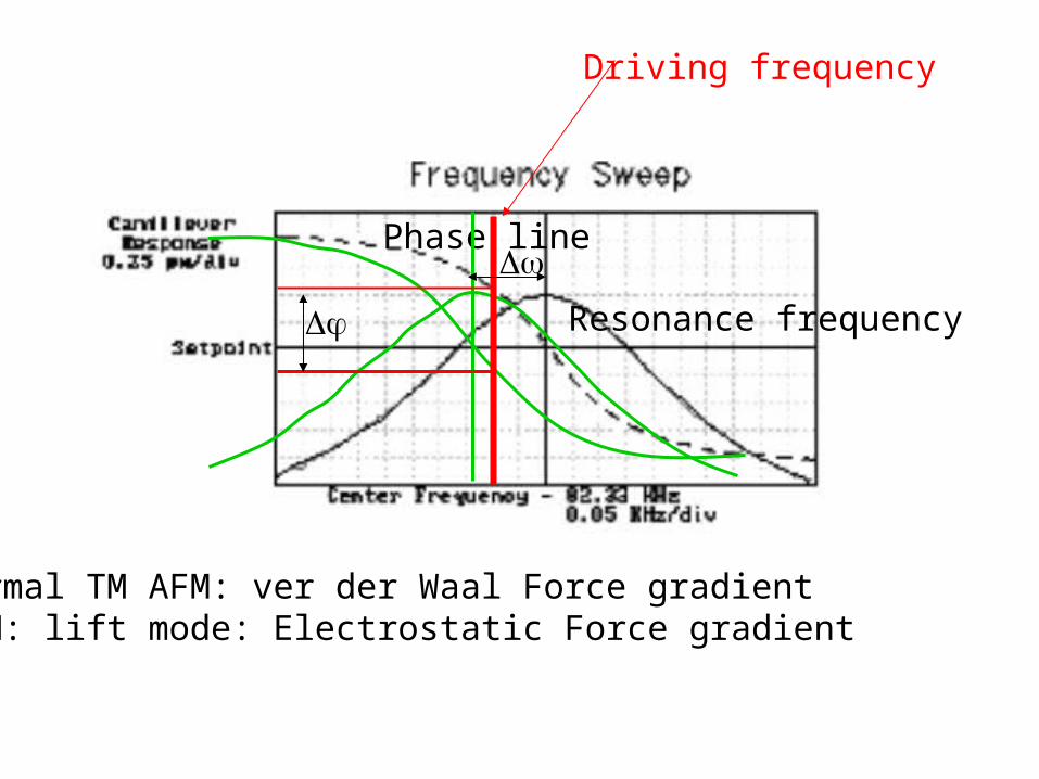
Resonance frequency
Phase line
Driving frequency
Normal TM AFM: ver der Waal Force gradientEFM: lift mode: Electrostatic Force gradient

Mechanical Driven Mode
V piezo = Vac sin(t+ 1)
Free cantilever: A1 (d) sin(dt)+ 1)Interacted cantilever: A2(d) sin( d t) + 2)
Constant drive frequency
Normal TM AFM: ver der Waal Force gradientEFM: lift mode: Electrostatic Force gradient
Electric Force Microscopy (EFM)
• Mechanical vibration given to tip
• Electric field will produce a change in phase of tip
• Measure phase lag relative to piezo drive signal.
• In most cases, it is necessary to apply a voltage across the tip or sample to achieve a high-quality image.
• Even if a layer of insulating material covered the conductive domains, they still can be detected.

EFM/MFM
Conductive Domains
Magnetic domains
Magnetic tip, instead of only a conductive tip
Piezoelectric materials
