tanase thesis
TRANSCRIPT
8/6/2019 Tanase Thesis
http://slidepdf.com/reader/full/tanase-thesis 1/85
DOCUMENTING FRAMEWORKS USING PATTERN LANGUAGES
An Abstract of a Thesis
Submitted
in Partial Fulfillment
of the Requirements for the Degree
Master of Science
Diana Irina Tanase
University of Northern Iowa
December 2003
8/6/2019 Tanase Thesis
http://slidepdf.com/reader/full/tanase-thesis 2/85
ABSTRACT
A framework is a domain specific reusable design of a system expressed as an
ensemble of abstract classes. Unlike a class library, frameworks provide not only
components, but also a structure for integrating those components, a predefined
interoperation between them, and often the basic skeleton of an application. These
features of a framework, help developers reduce development and testing time, reuse
generic functions, tailor solutions that are close to the requirements of the client, and
increase overall productivity and reliability.
The advantages of using a framework come at a price--the cost of learning and
understanding the hotspots of the framework, its interactions, and even its limitations.
Frameworks offer some customization facilities, but they can impose some restrictions
and may require special programming techniques, especially if the developer wants to
perform functionality outside of the defined scope of the framework. Thus, a good
documentation of the framework has a substantial impact on its success as a reusable
component and implicitly affects the overall quality of the software systems that result
from extending it.
Pattern languages were envisioned to provide support in scaffolding thearchitecture of a system. Software patterns make up the vocabulary of the
language, while the rules for their implementation and combination are
embedded in other patterns. The idea of defining software patterns as a way of documenting design problems and their solutions roots in the work of
Christopher Alexander, who researched and implemented the two concepts inthe context of urban planning.
The hypothesis supported in this thesis is that pattern languages can be used for
documenting a framework. This type of documentation can provide generic guidelines on
how classes can be combined to create semantically coherent parts of the derived

8/6/2019 Tanase Thesis
http://slidepdf.com/reader/full/tanase-thesis 3/85
application, and it discloses the hidden design details of the framework, together with
code examples.
This thesis underlines the different aspects involved in crafting and using a pattern
language for documenting the JHotDraw framework. Writing the pattern language for
this framework proved to be a time-consuming process that required a lot of technical
knowledge on pattern writing and pattern mining. The final artifact documents JHotDraw
core features and provides guidelines in taking design decisions, pondering solutions, and
underlining the forces that constraint the lifecycle of the system.
8/6/2019 Tanase Thesis
http://slidepdf.com/reader/full/tanase-thesis 4/85
DOCUMENTING FRAMEWORKS USING PATTERN LANGUAGES
A Thesis
Submitted
in Partial Fulfillment
of the Requirements for the Degree
Master of Science
Diana Irina Tanase
University of Northern Iowa
December 2003
8/6/2019 Tanase Thesis
http://slidepdf.com/reader/full/tanase-thesis 5/85
ACKNOWLEDGEMENTS
The author would like to thank Dr. Eugene Wallingford for his patience, support,
and suggestions. The constant exchange of ideas helped the author finalize this thesis and
better understand what pattern language writing entails.
The author would also like to thank Dr. Ben Schafer and Dr. Michael Prophet for
their valuable comments. This paper would not have the form and consistency that it does
now without their participations.
Lastly, the author would like to thank her family for their support and love.
Special thanks also to Brian Johnson for his help on formatting the final version of this
paper.
8/6/2019 Tanase Thesis
http://slidepdf.com/reader/full/tanase-thesis 6/85
TABLE OF CONTENTS
PAGE
LIST OF TABLES....................................................................................................... vii
LIST OF FIGURES .................................................................................................... viii
CHAPTER 1. INTRODUCTION ................................................................................. 1
Patterns and Pattern Languages .......................................................................... 2
Frameworks......................................................................................................... 3
Pattern-Based Documentation for Application Frameworks.............................. 5
Challenging Aspects of Elaborating a Pattern Language for Documenting a Framework................................................................................. 6
CHAPTER 2. A WHIRPOOL OF IDEAS ON PATTERNSAND PATTERN LANGUAGES ................................................................................... 8
In the Footsteps of Christopher Alexander ......................................................... 9
The Quality Without a Name.................................................................. 9
Pattern Formalism.............................................................................................. 11
Patterns Classifications and Relationships......................................................... 14
Key Aspects of Pattern Languages .................................................................... 18
How Patterns Combine to Form High-Level Patterns
Containing New Information ................................................................. 19
How a Pattern Language is Validated.................................................... 21
How Do We Dismiss an “Anti-Pattern” ................................................ 22
On Using Patterns and Pattern Languages............................................. 22
CHAPTER 3. A PATTERN LANGUAGE FOR DOCUMENTING
JHOTDRAW ................................................................................................................ 24
8/6/2019 Tanase Thesis
http://slidepdf.com/reader/full/tanase-thesis 7/85

8/6/2019 Tanase Thesis
http://slidepdf.com/reader/full/tanase-thesis 8/85
APPENDIX B: FACTORY METHOD PATTERN ...................................................... 74

8/6/2019 Tanase Thesis
http://slidepdf.com/reader/full/tanase-thesis 9/85
LIST OF TABLES
TABLE PAGE
1
2
9
10
13
Pattern Description................................................................................................ 12
Pattern Classification ........................................................................................... 14
4 Natural language vs. Pattern language.................................................................. 19
Classes Description............................................................................................... 32
Design Patterns Embedded in JHotDraw.............................................................. 33
Pattern Language Summary.................................................................................. 58
8/6/2019 Tanase Thesis
http://slidepdf.com/reader/full/tanase-thesis 10/85
LIST OF FIGURES
FIGURE PAGE
3 Classification of Pattern Relationships ................................................................. 17
5 HotDraw Pattern Language................................................................................... 21
6 Framework Documentation Pyramid.................................................................... 27
7 JHotDraw’s Pattern Language Connective Map................................................... 29
8 Overview of JHotDraw’s Framework................................................................... 31
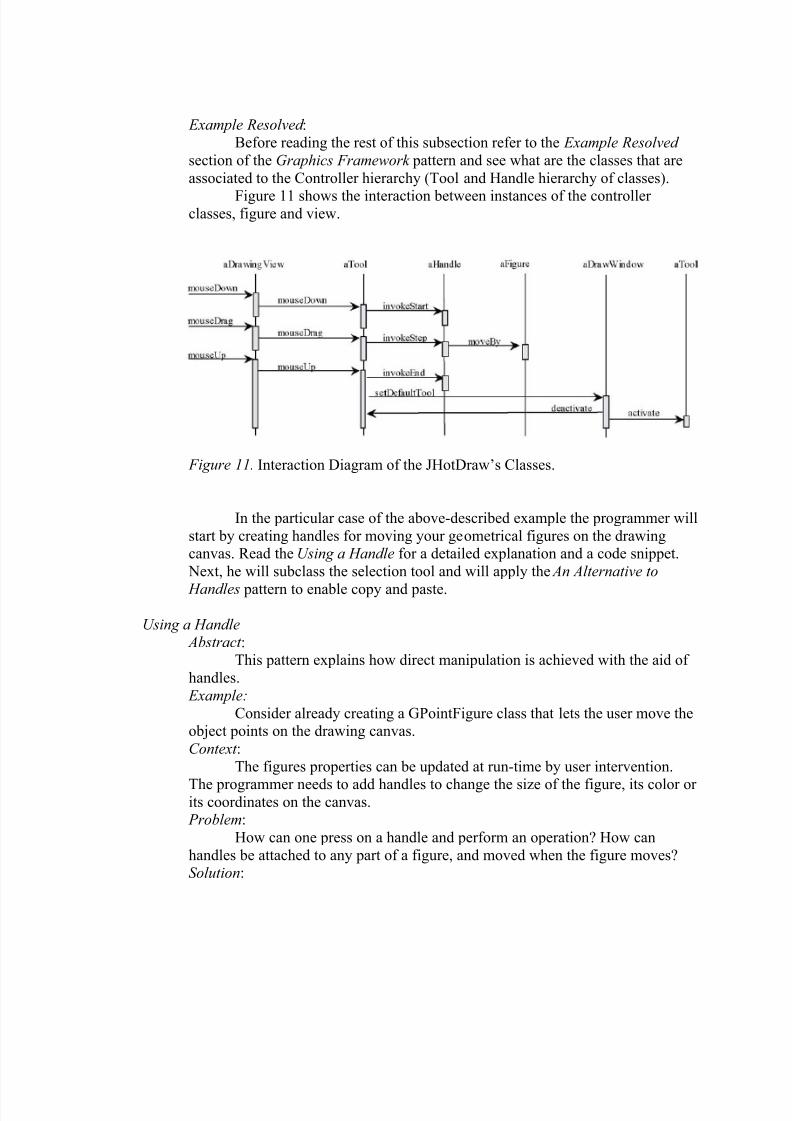
11 Interaction Diagram of the JHotDraw’s Classes.................................................. 41
12 SolarSystemTool Screenshot ............................................................................... 50
14 Factory Method Representation in LePUS ...........................................................73
15 Factory Method UML Diagram........................................................................... 74
8/6/2019 Tanase Thesis
http://slidepdf.com/reader/full/tanase-thesis 11/85
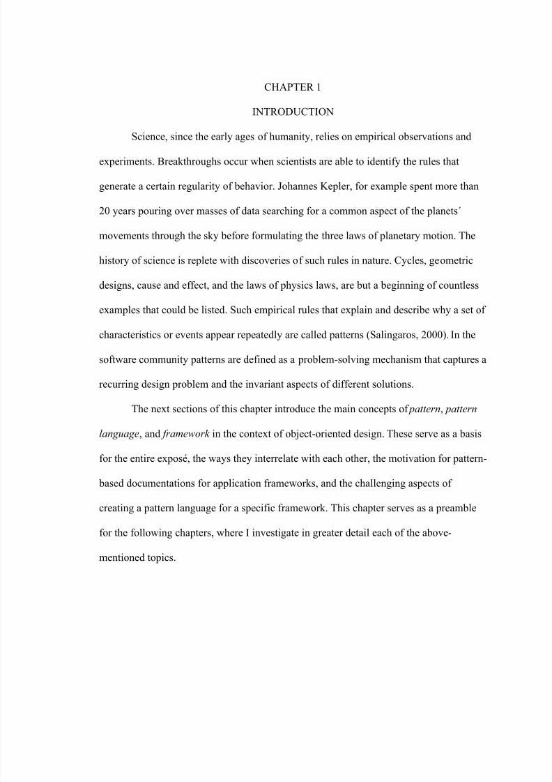
CHAPTER 1
INTRODUCTION
Science, since the early ages of humanity, relies on empirical observations and
experiments. Breakthroughs occur when scientists are able to identify the rules that
generate a certain regularity of behavior. Johannes Kepler, for example spent more than
20 years pouring over masses of data searching for a common aspect of the planets´
movements through the sky before formulating the three laws of planetary motion. The
history of science is replete with discoveries of such rules in nature. Cycles, geometric
designs, cause and effect, and the laws of physics laws, are but a beginning of countless
examples that could be listed. Such empirical rules that explain and describe why a set of
characteristics or events appear repeatedly are called patterns (Salingaros, 2000). In the
software community patterns are defined as a problem-solving mechanism that captures a
recurring design problem and the invariant aspects of different solutions.
The next sections of this chapter introduce the main concepts of pattern, pattern
language, and framework in the context of object-oriented design. These serve as a basis
for the entire exposé, the ways they interrelate with each other, the motivation for pattern-
based documentations for application frameworks, and the challenging aspects of
creating a pattern language for a specific framework. This chapter serves as a preamble
for the following chapters, where I investigate in greater detail each of the above-
mentioned topics.
8/6/2019 Tanase Thesis
http://slidepdf.com/reader/full/tanase-thesis 12/85
Patterns and Pattern Languages
The pattern concept roots in Christopher Alexander's work on urban planning and
building architecture. He gave the first definition of a design pattern in his book The
Timeless Way of Building (1979):
A pattern is a three-part rule, which expresses a relation between a certain
context, a problem, and a solution.
As an element in the world, each pattern is a relationship between a certain
context , a certain system of forces which occurs repeatedly in that context, and a
certain spatial configuration which allows these forces to resolve themselves.
As an element of language, a pattern is an instruction, which shows how thisspatial configuration can be used, over and over again, to resolve the given system
of forces, wherever the context makes it relevant (Alexander, 1979, p. 247).
Software developers have translated this in terms of software design, and the
pattern concept is used to represent a mechanism for capturing existing, well-proven
expertise in software development, as well to promote consistency and quality through
the course of design and implementation. Effective combinations of patterns that solved
specific problems allowed scalable and flexible architectures to be constructed. Patterns
were defined as a means of communicating design knowledge by providing a common
vocabulary for different stakeholders (designers, users, implementers).
The first book about design patterns, Design Patterns, Elements of Reusable
Design (Gamma, Johnson, & Vlissides, 1995), is commonly known as the “gang of
four”(GoF) book. Its content was organized as a catalog of solutions to commonly
occurring design problems, presenting twenty-three patterns that allow designers to create
flexible and reusable designs for object-oriented software. It also provided descriptions of
the circumstances in which each pattern is applicable, and discusses the consequences
8/6/2019 Tanase Thesis
http://slidepdf.com/reader/full/tanase-thesis 13/85
and trade-offs of using the pattern within a larger design. The patterns are compiled from
real systems, and include code for implementation in object-oriented programming
languages like C++ and Smalltalk.
When people started to use this pattern catalog they noticed that there was no glue
to connect these patterns together as a whole in a final well-formed product. A relational
hierarchy was necessary in order to induce a certain sequence when applying patterns,
and therefore to help scaffold the overall structure of a system. The inability to create
such a hierarchy was, due in part to the patterns formalism that is based on a natural
language narrative style. This difficulty has yet to be overcome, though some attempts in
this direction were pursued by A.H. Eden (2000).
The concept of pattern language was introduced as a response to the prior
mentioned issue. In comparison to pattern catalogs, a pattern language defines semantic
connection between patterns that help developers select cohesive sets of patterns that
work together towards fulfilling a shared objective in an orderly fashion. The objective is
to generate a domain specific application. Pattern languages have been conceived for a
variety of application domains including distributed systems (Aarsten, Brugali, & Menga,
1996), parallel programming (McKenny, 1996), and relational databases (Keller &
Coldewey, 1996).
Frameworks
A framework is a domain specific reusable design of a system expressed as an
ensemble of abstract classes. Unlike a class library, frameworks provide not only
components, but also a structure for integrating those components, a predefined
8/6/2019 Tanase Thesis
http://slidepdf.com/reader/full/tanase-thesis 14/85
interoperation between them, and often the basic skeleton of an application. The skeleton
is not passive like a class library, but has its own execution path from which user-defined
component code is called.
Due to the above-mentioned attributes of a framework, developers can reduce
development and testing time, reuse generic functions, tailor solutions that are close to
the client’s requirements, and increase overall productivity and reliability.
An often-used framework is the Java Media Framework (JMF). This embeds the
necessary functionality for developing applications for streaming audio or video files,
media presentations (presentations controllers), media processing (demultiplexers, codes,
effect filters), and media capture clocks for synchronization of different media, such as
audio and video output.
Another example is HotDraw, which is a framework that targets applications for
drawing technical and structured graphics such as network layouts and Pert diagrams, and
offers support to develop editors for those purposes.
JHotDraw is the Java implementation of HotDraw, which was invented in the mid
'80s at Tektronix by Ward Cunningham and Kent Beck. It was originally written in the
Tektronix version of Smalltalk-80, but many other versions have been written since then.
The implementation that will serve as a basis for the pattern language case study in
Chapter 3, is the one written by Erich Gamma for IBM Smalltalk (Johnson, 1992). The advantages of using a framework come at a price--the cost of learning and
understanding a framework's hotspots (the extension points where the new code should
be attached), its interactions, and even its limitations. Most frameworks are rather

8/6/2019 Tanase Thesis
http://slidepdf.com/reader/full/tanase-thesis 15/85
complex pieces of software at high levels of abstraction. Understanding a framework can
be difficult, and debugging framework code is sometimes cumbersome. Frameworks
offer some customization facilities, but they can impose some restrictions and may
require special programming techniques, especially if the developer wants to perform
functionality slightly out of the defined scope of the framework.
Pattern-Based Documentation for Application Frameworks
Using a framework involves having a good understanding of the followings
aspects: strengths and weaknesses, target applications, components and structure. All this
information is grouped together in the documentation of the framework, which consists
of UML class diagrams or interaction diagrams, a listing of classes and their methods,
and suggestions on what classes should be subclassed by the client application to
accomplish a certain task.
For instance JHotDraw’s documentation comprises a class reference guide, some
coding examples, and a narrative description of the overall design. The JavaDoc API also
provides additional information on the different design patterns embedded by the
framework.
Typically, to extend this framework the developer provides application-specific
subclasses (implementations) for some of the framework’s classes (interfaces), thus
allowing application-specific code to be called by the framework. Hence such base
classes in the framework can be regarded as a “specialization interface” of the
framework. But the extension points (like subclasses) are usually not independent of each
other. As a concrete example, each introduction of an application-specific subclasss for a
8/6/2019 Tanase Thesis
http://slidepdf.com/reader/full/tanase-thesis 16/85
framework class requires code in some other application class for instantiating that
subclass. Hence the two extension points depend strongly on each other. Without
understanding the relationships of individual extension points an application developer
cannot hope to understand the platform as an implementation paradigm (Hakala,
Hautamaki, Koskimies & Savolainen, 2000).
This leads to the following problem: “How can a framework be documented so
that developers can assimilate its structure and its code in a shorter amount of time”? The
hypothesis in this thesis is that a domain specific pattern language can address this
problem because it can provide generic guidelines on how classes can be combined to
create semantically coherent parts of the derived application, and it discloses the hidden
design details of the framework, together with code examples. The problem, now,
becomes discovering the right patterns and organizing them as a pattern language (Braga,
Felipe, Haeusler, & Lucena, 2000).
Challenging Aspects of Elaborating a Pattern Language for Documenting a Framework
The crafting of a pattern language is an incremental process that involves domain-
related pattern definition, discovery of additional patterns to glue them as a whole, and
assessment of the final collection. The resulting language should be an open set to which
new patterns can be continuously added and refined by the developers’ community. And
these are not all the difficulties that can be encountered. It is also hard to completely
cover the functionality of a framework, because developers often identify new extensions
that the framework’s creator did not anticipate.

8/6/2019 Tanase Thesis
http://slidepdf.com/reader/full/tanase-thesis 17/85
In conclusion, there are three aspects that determine the adequacy of a pattern
language for documenting a framework: accuracy, completeness, and expandability. In
the context of writing a pattern language for describing a framework these forces need to
be balanced.
This chapter’s overview of the main ideas and concepts on patterns, pattern
languages and frameworks, serves as a basis for the next chapters that present in detail
the emergence of patterns and pattern languages in the software community, and the
problematic aspects of using, building and validating a pattern language for documenting
JHotDraw.
8/6/2019 Tanase Thesis
http://slidepdf.com/reader/full/tanase-thesis 18/85
CHAPTER 2
A WHIRPOOL OF IDEAS ON PATTERNS AND PATTERN LANGUAGES
In the 1980s the software community was animated by the birth of two new
concepts: pattern (a description of a commonly encountered design problem and a
suggested solution) and pattern language (a set of connected patterns for a specific
domain--like urban architecture).
Christopher Alexander’s work in the ‘70s served as a theoretical basis for the
thousands of books, and articles that were published about patterns and pattern languages.
A decade later a new-formed pattern community was concentrating its efforts to establish
a solid ground for the emerging approach of “pattern-based” programming.
This chapter is an exploration of the existing body of literature on patterns and
pattern languages. It is structured in four sections, each complementing the general ideas
regarding patterns and pattern languages that were introduced previously. The first
section ( In the footsteps of Christopher Alexander ) gives an outline of the “quality
without a name” and the existing correlation between this quality of a pattern, and the
quality of the software, while the following section ( Pattern formalism) specifies
different pattern formalisms adopted by the pattern community in the last decade. The
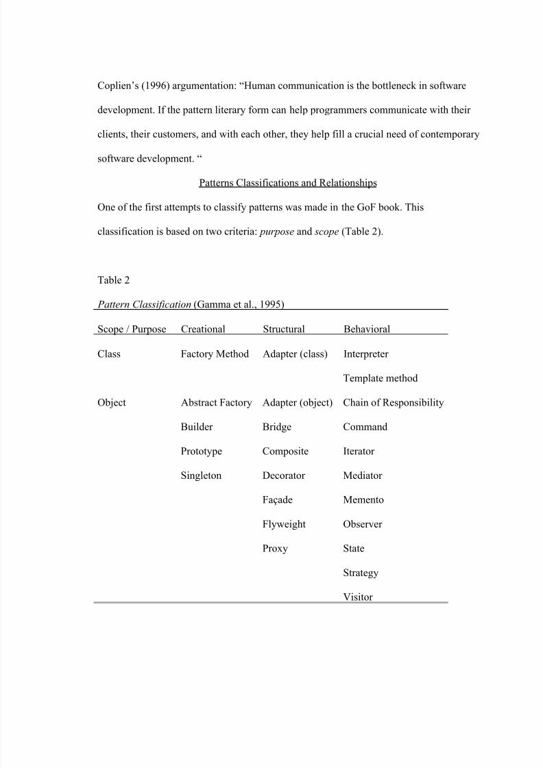
third section ( Patterns classifications and relationships) summarizes the fundamental
classification and relationships that exist between patterns, followed by an overview of
the most important issues that have to be taken into consideration by a pattern writer such
as combining patterns, validation, and use ( Key aspects of pattern languages).
8/6/2019 Tanase Thesis
http://slidepdf.com/reader/full/tanase-thesis 19/85
In the Footsteps of Christopher Alexander
The “patterns movement” has its origins in the work of Christopher Alexander.
His work on patterns is structured in three fundamental volumes. Volume I, The Timeless
Way of Building (1979) provides theoretical instruction for the use of a pattern language.
Volume II, A Pattern Language (1977) describes in detail a language for building and
planning. Volume III, The Oregon Experiment (1975) offers a “practical manifestation of
the theoretical ideas”(Alexander, 1975) presented in the first two mentioned volumes.
Each volume can be read separately, but all together they create a complete, coherent
view of the importance of a pattern language for architectural design. The next sections
of this chapter investigate the main ideas concentrated in these books.
The Quality Without a Name
The Timeless Way of Building introduces the “quality without a name” that is
“[…] the root criterion of life and spirit in a man, a town, a building, or a wilderness”
(Alexander, 1979, p. 19). This quality is objective, precise, cannot be named and it
endows patterns with the following characteristics:
1. Universally recognizable aesthetic beauty and order,
2. Recursively nested centers of symmetry and balance,
3. Life and wholeness,
4. Resilience, adaptability, and durability,
5. Human comfort and satisfaction,
6. Emotional and cognitive resonance.
8/6/2019 Tanase Thesis
http://slidepdf.com/reader/full/tanase-thesis 20/85
Therefore, using patterns that have the “quality without a name” improves the
human condition, giving people a sense of balance and integration of their work in a
larger system.
At first sight, this “quality” might seem philosophical in essence and not really
related to software design or software development. Thus, skimming through this first
volume, a programmer may wonder: “How does this quality help me through the daily
struggles with deadlines and requirements”? Richard Gabriel gives an answer to this in
Patterns of Software (1996). In the following, he describes the software that possesses
Alexander’s “quality without a name”:
Its modules and abstractions are not too big. If they were too big, their size and
inflexibility would have created forces that would over govern the overall
structure of the software; every module, function, class, and abstraction is smalland named so that I know what it is without looking at its implementation.
If I look at any small part of it, I can see what is going on, I don’t need to refer toother parts to understand what something is doing. This tells me that the
abstractions make sense for themselves--they are a whole.
If I look at any large part in overview, I can see what is going on, I don’t need to
know all the details to get it.
Everything about it seems familiar.
I can imagine changing it, adding some functionality.
I am not afraid of it, I will remember it (Gabriel, 1996, p. 100).
Gabriel’s quote echoes in the mind of every programmer who has sat down and
performed maintenance of a large piece of code, or worked in teams where he/she had to
develop a new module on top of an already existing structure. Though the software’s
“quality without a name” is deeply embedded inside the scaffolding patterns, it has a halo
8/6/2019 Tanase Thesis
http://slidepdf.com/reader/full/tanase-thesis 21/85
effect on both the program and the developer. To clarify this matter, it can be rephrased
in terms of cause and effect:
Cause: a programmer chooses to use patterns to solve design problems;
Effect : the resulting artifact is the expression of recurrence, familiarity; it is
predictable, balanced, and harmonious; it is a well-written piece of code, and the
programmer feels confident that his design solution will work.
Pattern Formalism
Alexander defined a pattern as both a recurring solution to a particular problem in
a certain context and also a documentation of that solution. Thus, someone who would
want to write a pattern also needs to think about how to structure and organize the
problem, the solution, and the context, so that it can be communicated to almost anyone.
In Fine Points of Pattern Writing , Gabriel captures the gist of the three-part rule
components: forces “teach about the area—what is difficult, what is the landscape like,
what is easy”, the problem is “a set of circumstances someone could notice, usually
while building something”, and the solution “falls out of the discussion of the forces and
other teaching about the situation”. He concludes with the idea that the final written
version of the pattern is valid if “it seems familiar to an expert but even the expert should
feel enlightened by the discussion”.
Alexander initiated one of the first pattern formalisms in A Pattern Language
(1977). He used both visual representations (photographs for the contexts, schematic
diagrams for the solutions, etc.) and English narrations (for the problem and the forces)
for documenting patterns.
8/6/2019 Tanase Thesis
http://slidepdf.com/reader/full/tanase-thesis 22/85
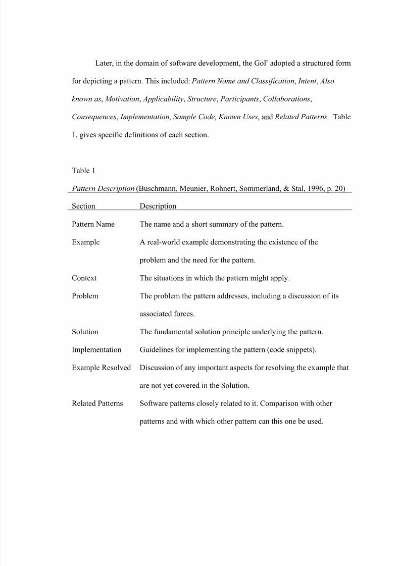
Later, in the domain of software development, the GoF adopted a structured form
for depicting a pattern. This included: Pattern Name and Classification, Intent , Also
known as, Motivation, Applicability, Structure, Participants, Collaborations,
Consequences, Implementation, Sample Code, Known Uses, and Related Patterns. Table
1, gives specific definitions of each section.
Table 1
Pattern Description (Buschmann, Meunier, Rohnert, Sommerland, & Stal, 1996, p. 20)
Section Description
Pattern Name
Example
Context
Problem
Solution
Implementation
Example Resolved
Related Patterns
The name and a short summary of the pattern.
A real-world example demonstrating the existence of the
problem and the need for the pattern.
The situations in which the pattern might apply.
The problem the pattern addresses, including a discussion of its
associated forces.
The fundamental solution principle underlying the pattern.
Guidelines for implementing the pattern (code snippets).
Discussion of any important aspects for resolving the example that
are not yet covered in the Solution.
Software patterns closely related to it. Comparison with other
patterns and with which other pattern can this one be used.
8/6/2019 Tanase Thesis
http://slidepdf.com/reader/full/tanase-thesis 23/85
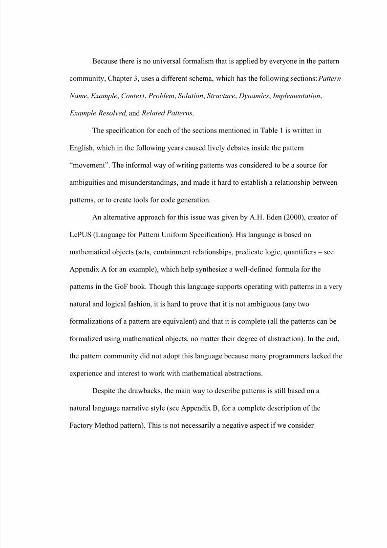
Because there is no universal formalism that is applied by everyone in the pattern
community, Chapter 3, uses a different schema, which has the following sections: Pattern
Name, Example, Context , Problem, Solution, Structure, Dynamics, Implementation,
Example Resolved , and Related Patterns.
The specification for each of the sections mentioned in Table 1 is written in
English, which in the following years caused lively debates inside the pattern
“movement”. The informal way of writing patterns was considered to be a source for
ambiguities and misunderstandings, and made it hard to establish a relationship between
patterns, or to create tools for code generation.
An alternative approach for this issue was given by A.H. Eden (2000), creator of
LePUS (Language for Pattern Uniform Specification). His language is based on
mathematical objects (sets, containment relationships, predicate logic, quantifiers – see
Appendix A for an example), which help synthesize a well-defined formula for the
patterns in the GoF book. Though this language supports operating with patterns in a very
natural and logical fashion, it is hard to prove that it is not ambiguous (any two
formalizations of a pattern are equivalent) and that it is complete (all the patterns can be
formalized using mathematical objects, no matter their degree of abstraction). In the end,
the pattern community did not adopt this language because many programmers lacked the
experience and interest to work with mathematical abstractions.
Despite the drawbacks, the main way to describe patterns is still based on a
natural language narrative style (see Appendix B, for a complete description of the
Factory Method pattern). This is not necessarily a negative aspect if we consider
8/6/2019 Tanase Thesis
http://slidepdf.com/reader/full/tanase-thesis 24/85

8/6/2019 Tanase Thesis
http://slidepdf.com/reader/full/tanase-thesis 25/85
8/6/2019 Tanase Thesis
http://slidepdf.com/reader/full/tanase-thesis 26/85
in the catalog that could be coupled with the initial one or patterns that were closely
related. Because this initial catalog of patterns was relatively small (only 23 patterns),
this approach was sufficient for those who were trying to learn how to use patterns
together.
Later Zimmer divided these relationships further giving a basis for deeper
understanding of the patterns. He noticed that there is no classification of the
relationships in (Gamma et al., 1995) so he defined three categories of relationships:
1. X uses Y in its solution. When solving the problem that X addresses, Y might
solve one of the sub problems. Thus Y makes up a part of X. A possible use for relations
in this group is in a development tool. The Y pattern can be displayed as a “black box”,
inside the implementation of X.
2. X is similar to Y . The two patterns address a similar kind of problem. This does
not mean that the solutions are similar. This kind of relation is often reflected in the
classification in (Gamma et al., 1995). This class can be very useful when searching for
patterns to use.
3. X can be combined with Y. Two patterns are typically combined. This is not the
same as X uses Y in its solution. None of the participating patterns are actually part of the
other. This kind of relations is also useful for retrieving patterns. If one pattern is used,
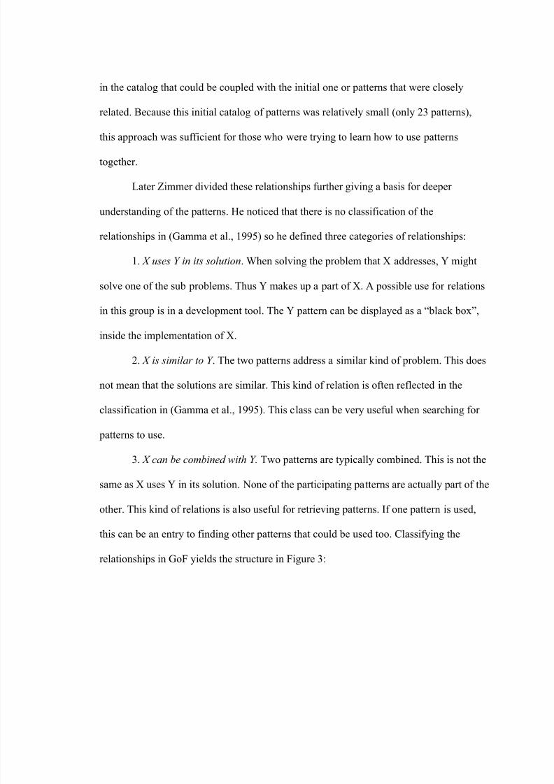
this can be an entry to finding other patterns that could be used too. Classifying the
relationships in GoF yields the structure in Figure 3:
8/6/2019 Tanase Thesis
http://slidepdf.com/reader/full/tanase-thesis 27/85
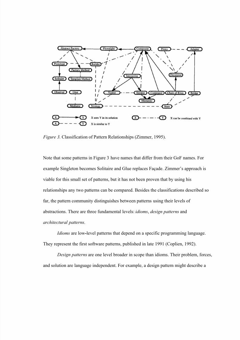
Figure 3. Classification of Pattern Relationships (Zimmer, 1995).
Note that some patterns in Figure 3 have names that differ from their GoF names. For
example Singleton becomes Solitaire and Glue replaces Façade. Zimmer’s approach is
viable for this small set of patterns, but it has not been proven that by using his
relationships any two patterns can be compared. Besides the classifications described so
far, the pattern community distinguishes between patterns using their levels of
abstractions. There are three fundamental levels: idioms, design patterns and
architectural patterns.
Idioms are low-level patterns that depend on a specific programming language.
They represent the first software patterns, published in late 1991 (Coplien, 1992).
Design patterns are one level broader in scope than idioms. Their problem, forces,
and solution are language independent. For example, a design pattern might describe a
8/6/2019 Tanase Thesis
http://slidepdf.com/reader/full/tanase-thesis 28/85
way to ensure there is only one instance of a class (the singleton pattern). An idiom might
describe a way to return multiple values in Java, given that the Java language does not
have a built-in multivalued return capability (Venners, 1998).
Architectural patterns give a structural organization schema for software systems.
They provide a set of predefined subsystems, specify their responsibilities, and include
rules and guidelines for organizing the relationships between them (Buschmann et al.,
1996). For example, the Layers pattern helps structuring applications that can be
decomposed into groups of subtasks in which each group of subtasks is at a particular
level of abstractions.
Key Aspects of Pattern Languages
From a mathematical standpoint, any language is represented by a set of elements
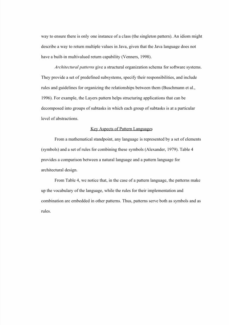
(symbols) and a set of rules for combining these symbols (Alexander, 1979). Table 4
provides a comparison between a natural language and a pattern language for
architectural design.
From Table 4, we notice that, in the case of a pattern language, the patterns make
up the vocabulary of the language, while the rules for their implementation and
combination are embedded in other patterns. Thus, patterns serve both as symbols and as
rules.
8/6/2019 Tanase Thesis
http://slidepdf.com/reader/full/tanase-thesis 29/85
Table 4
Natural language vs. Pattern language (Alexander, 1979, p.187)
Elements of the language Natural Language Pattern Language
Symbols Words Patterns
Rules
Combination of symbols
Rules of grammar, and
meaning which allow
connecting words.
Sentences
Patterns which specify
connections between
patterns.
Buildings and places in the
case of architectural
pattern languages.
How Patterns Combine to Form High-Level Patterns Containing New Information
From the section on pattern relationships we can derive several situations:
1. One pattern contains or generalizes another small-scale pattern.
2. Two patterns are complementary and one needs the other for completeness.
3. Two patterns solve different problems that overlap and coexist on the same
level.
4. Two patterns solve the same problem in alternative, equally valid ways
(Salingaros, 2000).
For Alexander’s pattern language the rules for combining two patterns are based
on the containment criterion:
Each pattern depends both on the smaller patterns it contains, and on the larger patterns within which it is contained. [...]
8/6/2019 Tanase Thesis
http://slidepdf.com/reader/full/tanase-thesis 30/85
And it is the network of these connections between patterns, which creates the
language. [...]
In this network, the links between the patterns are almost as much a part of thelanguage as the patterns themselves (Alexander, 1979, pp. 312-314).
In the generic case of a pattern language, the connective rules between two
patterns are harder to identify. Some authors (e.g. Borchers, 2001) have suggested a
formal modeling of pattern languages with the use of acyclic directed graphs, where the
nodes are the patterns, and the edges represent a relationship between the end patterns.
The advantage of this formalism is that it provides a layered visualization of the
language’s structure.
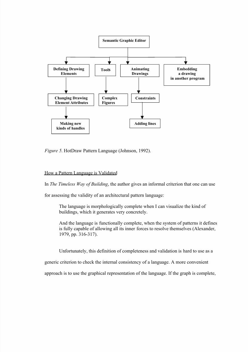
For example, Ralph Johnson (1992) presented one of the first experimental
pattern languages for documenting HotDraw. Figure 5 describes the outline of the
language organized as a directed graph.
Notice that the patterns are arranged so that those closest to the first pattern are
the ones that are used most often. For instance, the second pattern describes how to make
subclasses of Figure (one of the framework’s class), which is something that almost every
user of HotDraw needs to know (Johnson, 1992).
8/6/2019 Tanase Thesis
http://slidepdf.com/reader/full/tanase-thesis 31/85
Defining Drawing
Elements
Embedding
a drawing
in another program
Animating
DrawingsTools
Complex
Figures
Making newkinds of handles
Adding lines
Constraints
Semantic Graphic Editor
Changing Drawing
Element Attributes
Figure 5. HotDraw Pattern Language (Johnson, 1992).
How a Pattern Language is Validated
In The Timeless Way of Building , the author gives an informal criterion that one can use
for assessing the validity of an architectural pattern language:
The language is morphologically complete when I can visualize the kind of
buildings, which it generates very concretely.
And the language is functionally complete, when the system of patterns it defines
is fully capable of allowing all its inner forces to resolve themselves (Alexander,
1979, pp. 316-317).
Unfortunately, this definition of completeness and validation is hard to use as a
generic criterion to check the internal consistency of a language. A more convenient
approach is to use the graphical representation of the language. If the graph is complete,

8/6/2019 Tanase Thesis
http://slidepdf.com/reader/full/tanase-thesis 32/85
meaning that there are no isolated nodes and there exists a path between any two nodes,
then the language has good chances to be valid. For completeness there does not exist a
similar solution using graphs. That is why putting together a pattern language is an
extremely demanding task. Before moving on to the next section, another issue needs to
be addressed:
How Do We Dismiss an “Anti-Pattern”
Whenever a new symbol is added to a language it has to bring new information
that will integrate in the language’s landscape. This is the first test; the next is “the test of
time”. If the pattern manages to interrelate and coexist with the other patterns then we can
consider that “the test of time” was passed, and hence the pattern has gained its place.
On Using Patterns and Pattern Languages
The three most often-cited reasons for using patterns and pattern languages are:
1. Quality without a name. This intrinsic quality of patterns affect both on the
programmer or designer who uses them and the final product. Thus patterns facilitate the
construction of better designs, increase productivity, improve the quality of designs by
novices, encourage best practices and ensure high design quality even for experienced
developers.
2. Reuse. Patterns permit the re-use of the hard-won wisdom of designers,
allowing the accumulation and generalization of successful solutions to commonly
encountered problems (Vlissides, 1998).
3. Lingua Franca. Patterns have a number of representational properties that
make them useful as lingua franca: they have memorable names; they have associated

8/6/2019 Tanase Thesis
http://slidepdf.com/reader/full/tanase-thesis 33/85
images; and they have a well-structured documentation format (Erickson, 2000).
Thus, they are ideal communication tools between different stakeholders with unrelated
backgrounds.
Another goal of patterns is to help understand and document object-oriented
designs by providing a vocabulary to discuss and communicate design decisions in terms
of structures larger than modules, procedures, or objects, which make up the vocabulary
of programming languages. For example, Kent Beck and Ralph Johnson, in Patterns
Generate Architectures, mirror the incremental pattern-driven evolution of the
application framework HotDraw.
In conclusion, patterns and pattern languages encapsulate human experience and
help us justify and communicate design decisions at any level of abstractions. Based on
the theoretical ideas exposed in this chapter, the next chapter will describe a concrete
example of a pattern language for documenting JHotDraw.
8/6/2019 Tanase Thesis
http://slidepdf.com/reader/full/tanase-thesis 34/85
CHAPTER 3
A PATTERN LANGUAGE FOR DOCUMENTING JHOTDRAW
The greatest challenge for people who wish to benefit from the “quality without a
name” is to be able to think in terms of patterns when they design, program or document
software. Software patterns are not hardwired into the human mind. They require a
conscious effort. A developer needs to reason about the problem in order to identify the
pattern to be used, reconsider the chosen pattern if it does not integrate in the context of
the application, and avoid randomness when applying patterns. Thus, patterns operate on
a level of reflective practice, and ideally the developer internalizes them in his thinking
frame.
Humans can acquire the ability to employ software patterns the same way they
can learn a new language. The first step is to assimilate the meaning of simple words, and
then learn a few syntactic and semantic rules so the words can be used in sentences. The
next step is to gradually add more words to the core vocabulary so that the speech
becomes more expressive, varied, subtle and specific. Thus, thinking in terms of patterns
demands a good understanding of the three-part relation (problem-context-solution),
which captures the semantics of a pattern, and of the connectivity rules that couple
patterns together into cohesive, meaningful blocks that help generate architectures.
This chapter is structured around two key problems: how to build pattern
languages for specific domains ( A close-up on building a pattern language), and what are
the required features of a pattern language for documenting a framework (The essential
features of a pattern language for documenting frameworks). The solutions for these
8/6/2019 Tanase Thesis
http://slidepdf.com/reader/full/tanase-thesis 35/85
problems provide the theoretical foundations for the last section of the chapter ( An
experimental pattern language for documenting a graphics framework ), where a pattern
language for JHotDraw is described.
A Close-up on Building a Pattern Language
According to Coplien a “pattern language is a collection of patterns that build on
each other to generate a system” (Coplien, 1996, p. 25). In The Timeless Way of Building ,
Alexander structures the process of putting together a pattern language in a sequence of
steps. These steps are in accordance with the design process, which involves making
decisions on how a system is built, making tradeoffs between various alternatives, and
finding the set of alternatives most relevant to the problem that cooperatively solves the
problem. Here are the main stages, necessary for clustering patterns in a semantically
coherent set:
1. Select a set of patterns from an already existing catalog.
2. Add to that set any other related patterns (there exist some type of relationship
like the ones described by the pattern classification of Zimmer) to the ones included at
Step 1.
3. Do not include patterns that seem alike just to make sure that the set is
complete.
4. Adjust the initial set adding patterns that arise while actually designing and
implementing the application (Alexander, 1979).
Notice that the first three steps require a thorough selection of existing patterns
and a deep investigation of the relationships among them. If there are no more patterns to
8/6/2019 Tanase Thesis
http://slidepdf.com/reader/full/tanase-thesis 36/85
8/6/2019 Tanase Thesis
http://slidepdf.com/reader/full/tanase-thesis 37/85
set of patterns. The three major types of audiences that a pattern language writer should
consider are:
1. Users deciding which framework to use, who are looking for answers to
questions like: “What are the main characteristics of the framework? Is it appropriate for
my application “?
2. Users wanting to build a typical application, who want to identify the
“hotspots” of the framework and that need to know what classes should be subclassed to
benefit from the framework’s default behavior.
3. Users wanting to go beyond the typical use, who intend to add new components
and features, or customize the framework’s architecture (Johnson, 1992).
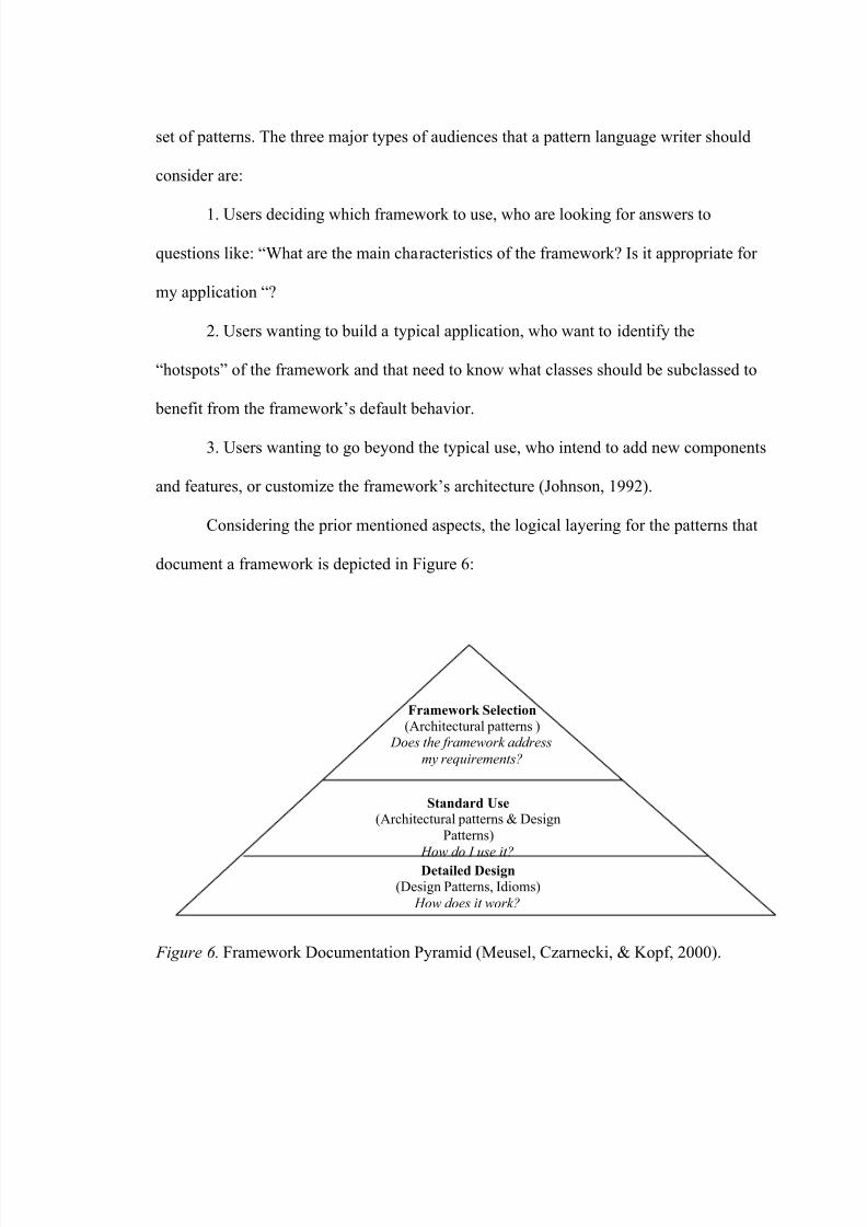
Considering the prior mentioned aspects, the logical layering for the patterns that
document a framework is depicted in Figure 6:
Detailed Design
(Design Patterns, Idioms)
How does it work?
Standard Use
(Architectural patterns & Design
Patterns)
How do I use it?
Framework Selection (Architectural patterns )
Does the framework address
my requirements?
Figure 6. Framework Documentation Pyramid (Meusel, Czarnecki, & Kopf, 2000).
8/6/2019 Tanase Thesis
http://slidepdf.com/reader/full/tanase-thesis 38/85
This pyramid also gives a horizontal criterion for organizing the pattern language
set. The standard documentation of a framework includes a description of its purpose,
hints on how to use it (code examples) and details about its design such as use-cases,
interaction diagrams, or UML class diagrams. The corresponding pattern language has to
capture all these aspects, using software patterns on different levels of abstraction. The
architectural patterns will define the main building blocks of the framework, while the
design patterns or the idioms will wrap the know-how for extending the initial
framework.
An Experimental Pattern Language for Documenting a Graphics Framework
This section describes a pattern language for a specific framework, namely
JHotDraw. This pattern language provides generic guidelines on what classes can be
combined and extended to accomplish certain tasks. It also discloses the hidden design
details of the framework together with code examples. The building process of this
language relied on Alexander’s step-by-step approach that is presented in the first section
of this chapter.
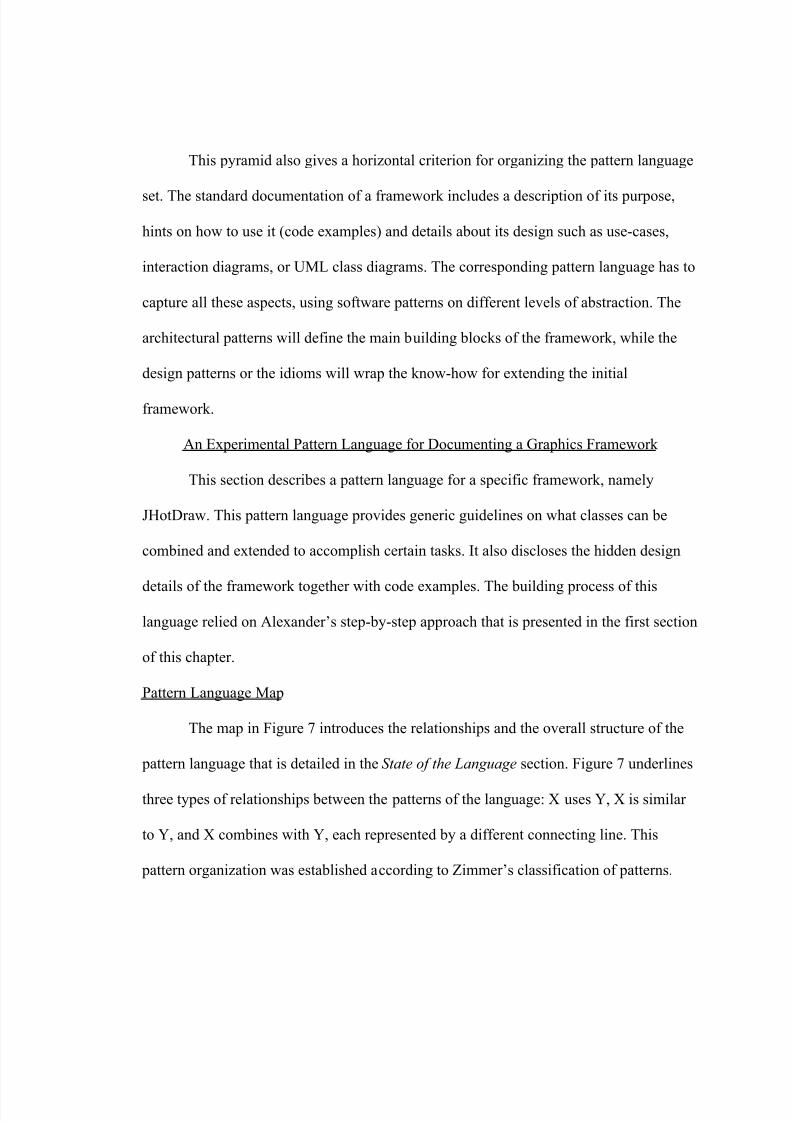
Pattern Language Map
The map in Figure 7 introduces the relationships and the overall structure of the
pattern language that is detailed in the State of the Language section. Figure 7 underlines
three types of relationships between the patterns of the language: X uses Y, X is similar
to Y, and X combines with Y, each represented by a different connecting line. This
pattern organization was established according to Zimmer’s classification of patterns.
8/6/2019 Tanase Thesis
http://slidepdf.com/reader/full/tanase-thesis 39/85
Figure 7 . JHotDraw’s Pattern Language Connective Map.
Using a Handle
Creating a
Drawing Element
nimating a
Drawing
Embedding a Drawing in
nother Program
Serializing a
Drawing Element
Using Creation
Tool
Changing thettributes of a
Drawing Element
Composing
Drawing Elements Creating
Constraints
between Drawing
Elements
n Alternative to
Handles
Creating a Custom
pplication
Selecting a Graphics Framework
X uses Y in its solutionY
Y X is similar to Y
Y X can be combined with Y
State of the Language
This pattern language attempts to cover the main functionalities of JHotDraw. It is
by no means an exhaustive description of the framework’s application scope. Its purpose
is mainly experimental.
Building the pattern language required the implementation of three test
applications, which were intended to serve as mining material for my research. The
8/6/2019 Tanase Thesis
http://slidepdf.com/reader/full/tanase-thesis 40/85
programs resulted from using this framework are: a simple geometrical figure drawing
tool, a graphical implementation of Dijkstra’s algorithm for finding the shortest path
between two nodes in a graph, and a tool that animates the planets movements in the
solar system. The Example and Example Resolved sections of the pattern descriptions
present small extracts of code from these programs.
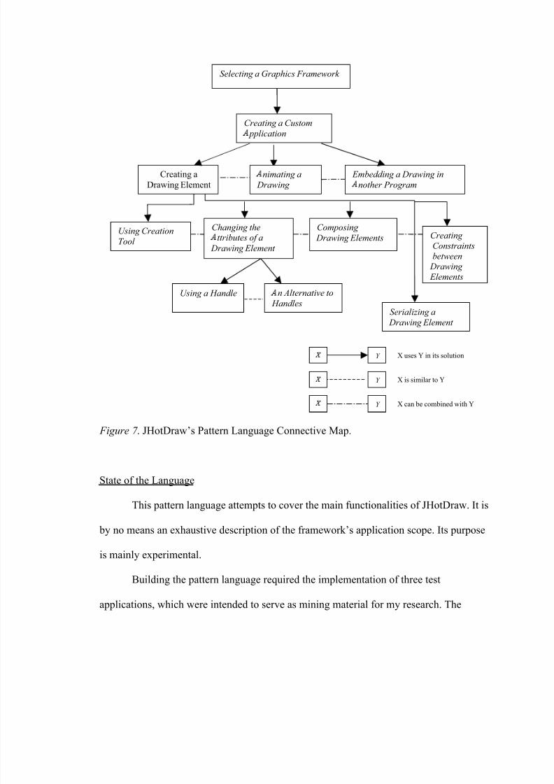
Framework Selection Pattern. The functionality and the architecture of a
framework are two aspects that are described separately in most existing documentation.
But for a developer it is more helpful if the two aspects are introduced together. With the
use of a mapping between the coarse blocks of classes and their functionality the
developer will be able to anticipate if the domain of the framework matches the domain
of the program he/she wants to build.
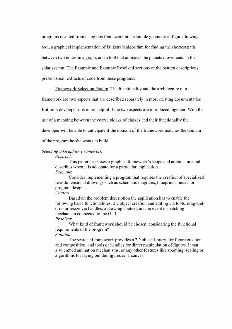
Selecting a Graphics Framework Abstract :
This pattern assesses a graphics framework’s scope and architecture and
describes when it is adequate for a particular application.
Example:Consider implementing a program that requires the creation of specialized
two-dimensional drawings such as schematic diagrams, blueprints, music, or program designs.
Context :
Based on the problem description the application has to enable the
following basic functionalities: 2D object creation and editing via tools, drag-and-drop or resize via handles, a drawing context, and an event dispatching
mechanism connected to the GUI.
Problem:
What kind of framework should be chosen, considering the functional
requirements of the program?Solution:
The searched framework provides a 2D object library, for figure creation
and composition, and tools or handles for direct manipulation of figures. It can
also embed animation mechanisms, or any other features like zooming, scaling or algorithms for laying out the figures on a canvas.
8/6/2019 Tanase Thesis
http://slidepdf.com/reader/full/tanase-thesis 41/85
The ground organizational structure should create a flexible context thatallows adjusting the presentational aspect of the application while the functional
one remains unchanged. The best approach for solving the layering problem is to
bias towards a framework that implements an architectural pattern like MVC
(Model-View-Controller) to separate the concerns. The Model will be responsiblefor maintaining state, and surfacing the behavior necessary to support the user
interface, the View will be responsible for displaying an up-to-date version of the
Model, and the Controller will be responsible for mapping user gestures tochanges of state in the model (Beck & Johnson, 1994).
Example Resolved :
An example of a graphics framework that offers support for technical andstructured graphics that was built on the MVC paradigm is JHotDraw. JHotDraw
has a set of predefined 2D figures (rectangles, ellipses, polygons, connection
lines, etc.) that can be combined into more complex drawings. The elements of these drawings can have constraints between them, react to user commands (like
delete, copy, paste, etc.), or they can be animated. The applications that extendJHotDraw can work as standalone, or as parts of larger systems.
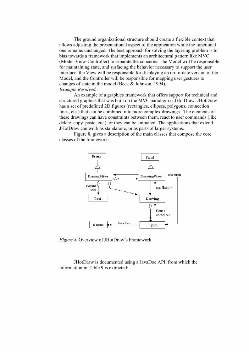
Figure 8, gives a description of the main classes that compose the coreclasses of the framework:
Figure 8. Overview of JHotDraw’s Framework.
JHotDraw is documented using a JavaDoc API, from which the
information in Table 9 is extracted:
8/6/2019 Tanase Thesis
http://slidepdf.com/reader/full/tanase-thesis 42/85
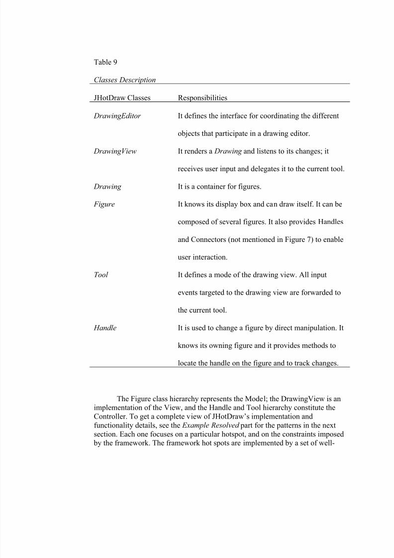
Table 9
Classes Description
JHotDraw Classes Responsibilities
DrawingEditor It defines the interface for coordinating the different
objects that participate in a drawing editor.
DrawingView It renders a Drawing and listens to its changes; it
receives user input and delegates it to the current tool.
Drawing It is a container for figures.
Figure It knows its display box and can draw itself. It can be
composed of several figures. It also provides Handles
and Connectors (not mentioned in Figure 7) to enable
user interaction.
Tool It defines a mode of the drawing view. All input
events targeted to the drawing view are forwarded to
the current tool.
Handle It is used to change a figure by direct manipulation. It
knows its owning figure and it provides methods to
locate the handle on the figure and to track changes.
The Figure class hierarchy represents the Model; the DrawingView is animplementation of the View, and the Handle and Tool hierarchy constitute the
Controller. To get a complete view of JHotDraw’s implementation and
functionality details, see the Example Resolved part for the patterns in the next
section. Each one focuses on a particular hotspot, and on the constraints imposed by the framework. The framework hot spots are implemented by a set of well-
8/6/2019 Tanase Thesis
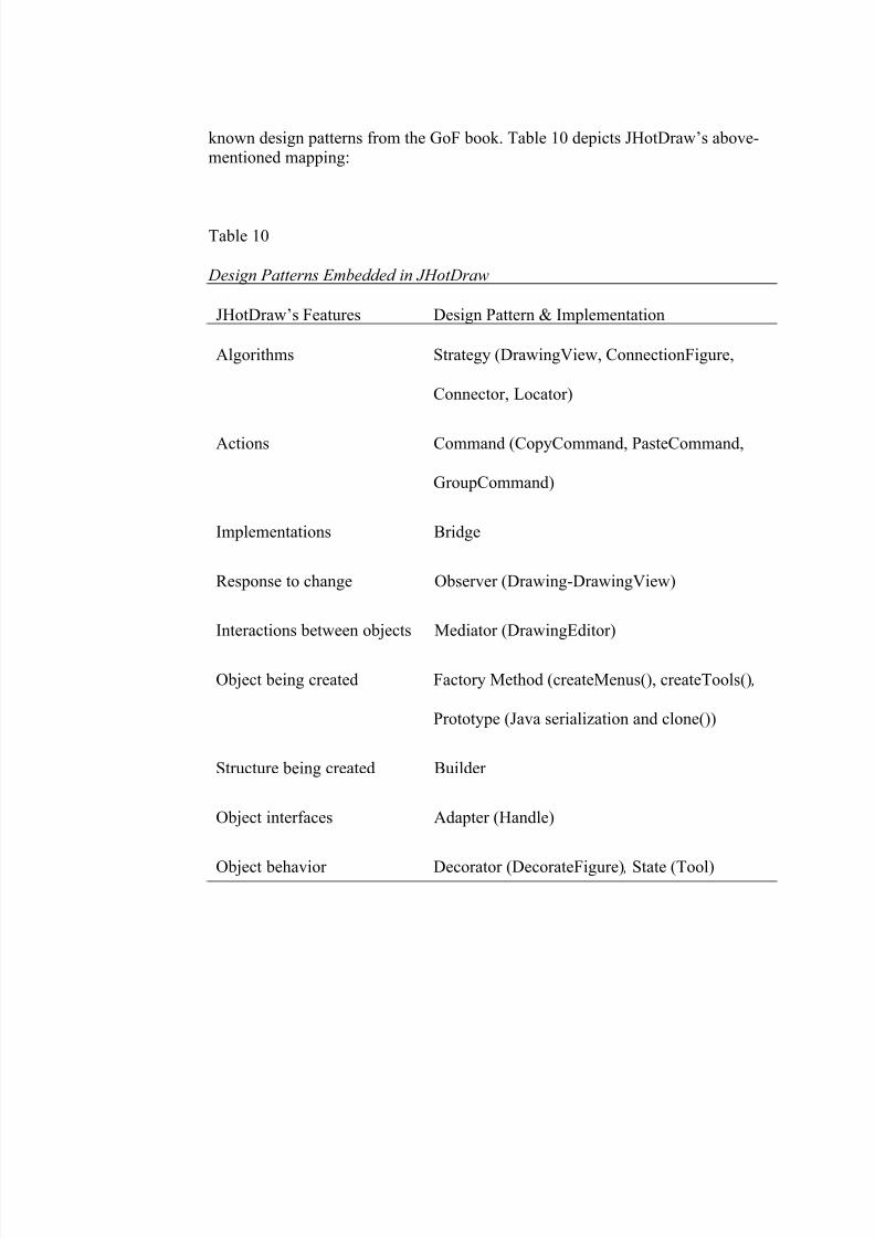
http://slidepdf.com/reader/full/tanase-thesis 43/85
known design patterns from the GoF book. Table 10 depicts JHotDraw’s above-mentioned mapping:
Table 10
Design Patterns Embedded in JHotDraw
JHotDraw’s Features Design Pattern & Implementation
Algorithms Strategy (DrawingView, ConnectionFigure,
Connector, Locator)
Actions Command (CopyCommand, PasteCommand,
GroupCommand)
Implementations Bridge
Response to change Observer (Drawing-DrawingView)
Interactions between objects Mediator (DrawingEditor)
Object being created Factory Method (createMenus(), createTools() ,
Prototype (Java serialization and clone())
Structure being created Builder
Object interfaces Adapter (Handle)
Object behavior Decorator (DecorateFigure) , State (Tool)
8/6/2019 Tanase Thesis
http://slidepdf.com/reader/full/tanase-thesis 44/85
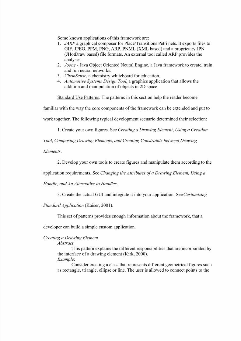
Some known applications of this framework are:1.
2.
3.4.
JARP a graphical composer for Place/Transitions Petri nets. It exports files to
GIF, JPEG, PPM, PNG, ARP, PNML (XML based) and a proprietary JPN
(JHotDraw based) file formats. An external tool called ARP provides the
analyses. Joone - Java Object Oriented Neural Engine, a Java framework to create, train
and run neural networks.ChemSense, a chemistry whiteboard for education. Automotive Systems Design Tool , a graphics application that allows the
addition and manipulation of objects in 2D space
Standard Use Patterns. The patterns in this section help the reader become
familiar with the way the core components of the framework can be extended and put to
work together. The following typical development scenario determined their selection:
1. Create your own figures. See Creating a Drawing Element , Using a Creation
Tool , Composing Drawing Elements, and Creating Constraints between Drawing
Elements.
2. Develop your own tools to create figures and manipulate them according to the
application requirements. See Changing the Attributes of a Drawing Element, Using a
Handle, and An Alternative to Handles.
3. Create the actual GUI and integrate it into your application. See Customizing
Standard Application (Kaiser, 2001).
This set of patterns provides enough information about the framework, that a
developer can build a simple custom application.
Creating a Drawing Element Abstract :
This pattern explains the different responsibilities that are incorporated by
the interface of a drawing element (Kirk, 2000). Example:
Consider creating a class that represents different geometrical figures such
as rectangle, triangle, ellipse or line. The user is allowed to connect points to the
8/6/2019 Tanase Thesis
http://slidepdf.com/reader/full/tanase-thesis 45/85
figure and name them, and move or resize figures using the mouse. Any other properties of the geometrical figure can be altered by direct manipulation.
Context :
A graphics framework includes a variety of primitive elements for
drawing (e.g., rectangles, circles, diamonds, lines). The standard implementationof the framework presents a toolbar from which the user selects the primitive
figure and drags it to the drawing area, menus for modifying the attributes of the
figure, and handles for changing a figures position on the canvas. A customapplication demands domain specific drawing elements.
Problem:
The custom figures are more complex (have a more elaborate interface)than the ones predefined by the framework. Thus, the designer needs to derive a
class that will integrate in the hierarchy of drawing elements supported by the
framework. Sometimes, the new class may require just tweaking the code for anexisting class, other times he will need to know how to combine several primitive
figures into the drawing entity that he wants. Assuming he identified the classeshe will use to create the graphical representation for the new figure, a new
problem appears: “How to connect the modifiers methods of the new class to theGUI so that the figure changes its internal status depending on user’s actions”?
This problem becomes even more complicated when altering one object causes
another one to change too. Thus, the events have to be synchronized. After hecreated the new figure class, the programmer needs to modify the standard
application so that the toolbar displays an icon for the new figure and that by
dragging it the user creates an instance of this new drawing element.Solution:
The problem stated above decomposes into several smaller problems:
combining figure classes into a composite figure class, connecting figures withthe user’s gestures, dispatching events according to the constraints existing
between objects, and making the new figures appear in the toolbar of the editor-like environment provided by the framework. To resolve the constraints between
these subproblems, the programmer should apply sequentially the following
patterns: Composing Drawing Elements, Changing the Attributes of a Drawing
Element , Creating Constraints between Drawing Elements, and Using a Creation
Tool . These patterns should be applied in the order suggested by the previous
enumeration, since one pattern creates the context for the next one. This tight
collaboration allows the programmer to define a nicely wrapped drawing elementclass that complies with other figures behavior.
Example resolved :For the JHotDraw framework the Figure represents the Model. The Figure
hierarchy defines the common graphical elements that can be added to a
JHotDraw application. At its root the interface Figure defines the common
operations that a figure can be asked to perform. The direct descendant of Figureis AbstractFigure, which defines much of the default behavior of Figure in
JHotDraw.
8/6/2019 Tanase Thesis
http://slidepdf.com/reader/full/tanase-thesis 46/85
The figures that are available for immediate reuse in JHotDrawapplications are defined in two subclasses of AbstractFigure. AttributeFigure
contains the majority with subclasses for all the common geometrical figures (i.e.
rectangles, ellipses, polygons etc) while PolyLineFigure contains one class,
LineFigure that represents lines on the drawing.All figures in JHotDraw are defined as rectangular areas within which a
visual element that represents the Figure is displayed. The rectangular area is
called the figure's display box and it is used to set the size and the position of afigure on the Drawing. Figures can have other attributes as well and the developer
should familiarize themselves with AbstractFigure and AttributeFigure where
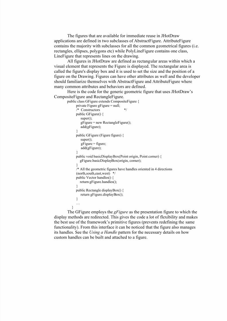
many common attributes and behaviors are defined.Here is the code for the generic geometric figure that uses JHotDraw’s
CompositeFigure and RectangleFigure. public class GFigure extends CompositeFigure {
private Figure gFigure = null;
/* Constructors */ public GFigure() {
super();
gFigure = new RectangleFigure();
add(gFigure);}
public GFigure (Figure figure) {
super();gFigure = figure;
add(gFigure);
}
public void basicDisplayBox(Point origin, Point corner) {gFigure.basicDisplayBox(origin, corner);
}
/* All the geometric figures have handles oriented in 4 directions(north,south,east,west) */
public Vector handles() {
return gFigure.handles();
} public Rectangle displayBox() {
return gFigure.displayBox();
}
…
}
The GFigure employs the gFigure as the presentation figure to which the
display methods are redirected. This gives the code a lot of flexibility and makesthe best use of the framework’s primitive figures (prevents redefining the same
functionality). From this interface it can be noticed that the figure also manages
its handles. See the Using a Handle pattern for the necessary details on howcustom handles can be built and attached to a figure.
8/6/2019 Tanase Thesis
http://slidepdf.com/reader/full/tanase-thesis 47/85
Using a Creation Tool Abstract :
This pattern brings forward the common way to add figures to a drawing
using a creation tool.
Example:Consider that the GFigure class was implemented and that it needs to be
embedded in the framework’s skeleton, such that the users will be able to click on
the corresponding toolbar icon and add it to the drawing canvas.Context :
Deriving the drawing elements from the framework’s package of figures is
just a first step towards customizing the framework. The next step is to integratethe new class in the internal collaborations that are predefined between the model-
view-controller classes. Problem:
The editor-like application that has to be built has a set of new figure
classes that subclass one of the figure classes of the framework. The current program does not know how to create instances of the new classes. The
programmer could implement classes for every type of object, but this approachwill generate lots of similar classes.Solution:
The above problem can be solved using the Prototype pattern, from theGoF book, by defining a class (CreationTool) that can be parameterized to create
any type of figure. The constructor of this class receives an instance (prototype) of
the type of figure to be created. Thus, this gives a uniform way for generating anynew figure.
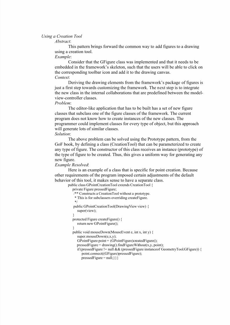
Example Resolved :
Here is an example of a class that is specific for point creation. Becauseother requirements of the program imposed certain adjustments of the default
behavior of this tool, it makes sense to have a separate class. public class GPointCreationTool extends CreationTool {
private Figure pressedFigure;
/** Constructs a CreationTool without a prototype.* This is for subclassers overriding createFigure.
*/
public GPointCreationTool(DrawingView view) {super(view);
}
protected Figure createFigure() {
return new GPointFigure();
} public void mouseDown(MouseEvent e, int x, int y) {
super.mouseDown(e,x,y);
GPointFigure point = (GPointFigure)createdFigure();
pressedFigure = drawing().findFigureWithout(x,y, point);if (pressedFigure != null && (pressedFigure instanceof GeometryTool.GFigure)) {
point.connect((GFigure)pressedFigure); pressedFigure = null;}}}
8/6/2019 Tanase Thesis
http://slidepdf.com/reader/full/tanase-thesis 48/85
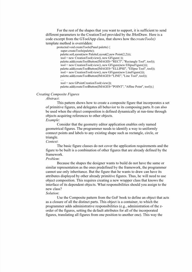
For the rest of the shapes that you want to support, it is sufficient to senddifferent parameters to the CreationTool provided by the JHotDraw. Here is a
code excerpt from the GToolApp class, that shows how the createTools()
template method is overridden:
protected void createTools(Panel palette) {super.createTools(palette);
palette.setLayout(new PaletteLayout(2,new Point(2,2)));
tool = new CreationTool(view(), new GFigure( ));
palette.add(createToolButton(IMAGES+"RECT", "Rectangle Tool", tool));tool = new CreationTool(view(), new GFigure(new EllipseFigure()));
palette.add(createToolButton(IMAGES+"ELLIPSE", "Ellipse Tool", tool));
tool = new CreationTool(view(), new GFigure(new LineFigure()));
palette.add(createToolButton(IMAGES+"LINE", "Line Tool", tool));
…tool = new GPointCreationTool(view());
palette.add(createToolButton(IMAGES+"POINT", "Affine Point", tool));}
Creating Composite Figures Abstract :This pattern shows how to create a composite figure that incorporates a set
of primitive figures, and delegates all behavior to its composing parts. It can also
be used when the object composition is defined dynamically at run-time throughobjects acquiring references to other objects.
Example:
Consider that the geometry editor application enables only namedgeometrical figures. The programmer needs to identify a way to uniformly
connect points and labels to any existing shape such as rectangle, circle, or
triangle.
Context : The basic figure classes do not cover the application requirements and the
figure to be built is a combination of other figures that are already defined by the
framework. Problem:
Because the shapes the designer wants to build do not have the same or
similar representation as the ones predefined by the framework, the programmer cannot use only inheritance. But the figure that he wants to draw can have its
attributes displayed by other already primitive figures. Thus, he will need to use
object composition. This requires creating a new wrapper class that knows theinterface of its dependent objects. What responsibilities should you assign to the
new class? Solution: Use the Composite pattern from the GoF book to define an object that acts
as a closure of all the distinct parts. This object is a container, to which the
programmer adds administrative responsibilities (e.g., administration of the z-
order of the figures, setting the default attributes for all of the incorporatedfigures, translating all figures from one position to another one). This way the
8/6/2019 Tanase Thesis
http://slidepdf.com/reader/full/tanase-thesis 49/85
client treats composite structures and individual objects uniformly, and it alsomakes it easier to add more features to the composite class. Another advantage is
that the programmer can specify any figure to take over the task for rendering the
graphical presentation at runtime. Modern frameworks might have an
implementation of the Composite pattern. Thus, exploring the primitive elementshierarchy of the framework and identifying that class is the recommendable step.
In any case the GoF book gives thorough instructions on how to instantiate the
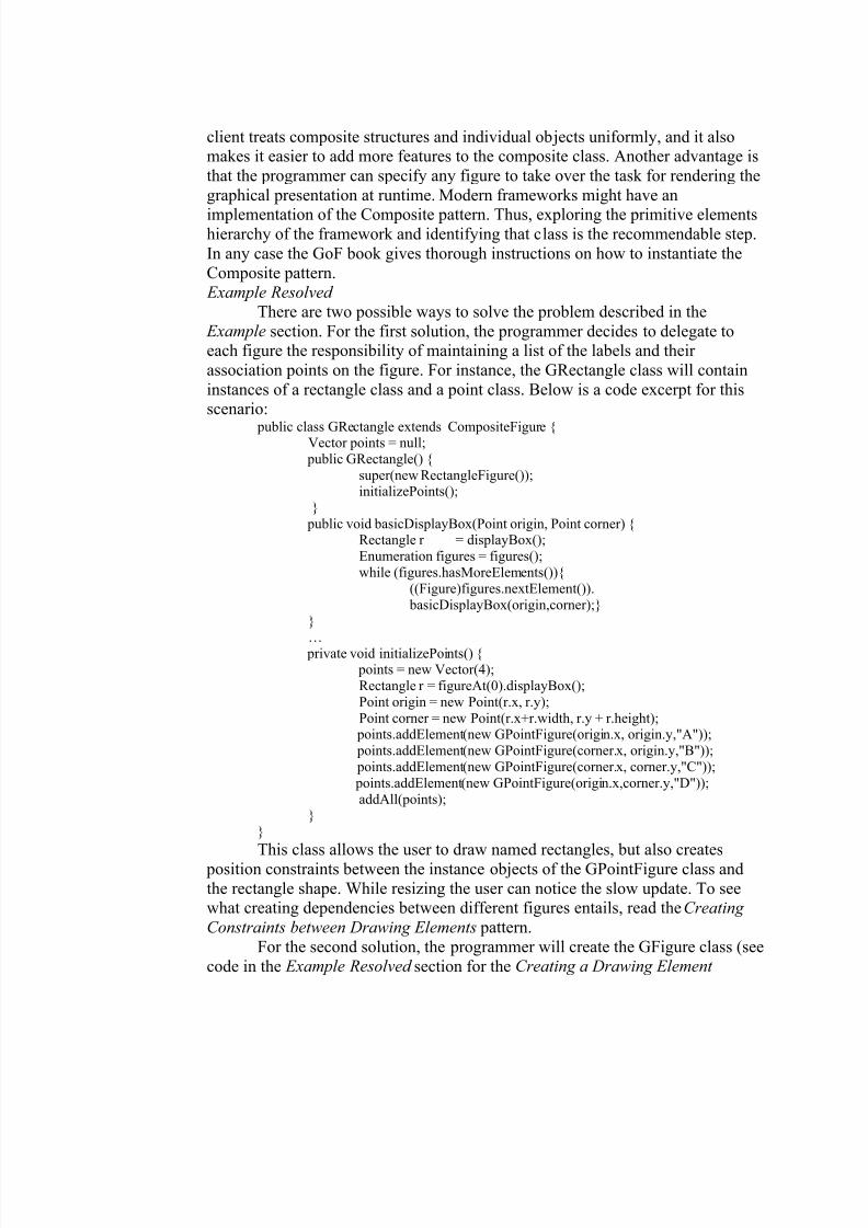
Composite pattern. Example Resolved
There are two possible ways to solve the problem described in the Example section. For the first solution, the programmer decides to delegate toeach figure the responsibility of maintaining a list of the labels and their
association points on the figure. For instance, the GRectangle class will contain
instances of a rectangle class and a point class. Below is a code excerpt for thisscenario:
public class GRectangle extends CompositeFigure {Vector points = null;
public GRectangle() {
super(new RectangleFigure());initializePoints();
}
public void basicDisplayBox(Point origin, Point corner) {Rectangle r = displayBox();
Enumeration figures = figures();
while (figures.hasMoreElements()){
((Figure)figures.nextElement()).
basicDisplayBox(origin,corner);}
}…
private void initializePoints() { points = new Vector(4);
Rectangle r = figureAt(0).displayBox();
Point origin = new Point(r.x, r.y);
Point corner = new Point(r.x+r.width, r.y + r.height); points.addElement(new GPointFigure(origin.x, origin.y,"A"));
points.addElement(new GPointFigure(corner.x, origin.y,"B"));
points.addElement(new GPointFigure(corner.x, corner.y,"C"));
points.addElement(new GPointFigure(origin.x,corner.y,"D"));
addAll(points);}
}
This class allows the user to draw named rectangles, but also creates
position constraints between the instance objects of the GPointFigure class and
the rectangle shape. While resizing the user can notice the slow update. To seewhat creating dependencies between different figures entails, read the Creating
Constraints between Drawing Elements pattern.
For the second solution, the programmer will create the GFigure class (see
code in the Example Resolved section for the Creating a Drawing Element
8/6/2019 Tanase Thesis
http://slidepdf.com/reader/full/tanase-thesis 50/85
pattern) that supports polymorphic composition (the graphical representation isdetermined at run-time). GFigure objects will only be aware of their own state.
Any points (instances of the GPointFigure class) that are attached to the figure
will register themselves as listeners of the GFigure object. The quick dispatch of
events overcomes the update problem mentioned in the first solution.
Changing the Attributes of a Figure Abstract :
This pattern describes what mechanisms are involved when the attributes
of a figure are changed. Example:
Consider that the GFigure class was already created, and the CreationTool
was parameterized. Therefore now, by clicking the toolbar buttons the user
manages to draw only fixed size figures that cannot be moved around the canvas.Yet, the user cannot cut or paste figures. Thus, the challenge is to find how can
these tasks be accomplished.Context :
The framework default editor environment groups tools and drawingstogether in a coherent structure, and enables figure changes, such as copy, and
paste (position change), resize and change colors, or fonts (appearance change),
and edit of the intrinsic attributes of a figure (behavioral change).
Problem:
How does the editor class initiate the corresponding controller for different
actions such as position, appearance or behavioral change? Keep in mind that the programmer might be dealing with a heterogeneous object collection (a variety of
figures) and he will be forced to find a generic way of mapping the object’s type
with the adequate tool or handler (controller).Solution:
The answer to the questions raised in the Problem section can be givenonly after the programmer dissociated the roles played by each of the classes that
are involved in changing the attributes of a figure. The interacting classes in this
problem are: a figure, tools, handles, and an editor class that sequences the flow
of actions and creates the context for the other classes to collaborate. Thus, thislast class plays the role of a mediator.
The editor class will manage the instance of the current tool. The tool
object alters its behavior when its internal state changes, based on the user’sselection from the toolbar. Thus, an instance of the State pattern from the GoF
book. Ultimately, the direct manipulation of figures is achieved through the use of handles, which play the Adapter role, by converting the interface of a figure classto another one that is known by the tool classes. This tackles the heterogeneity
issue mentioned above.
8/6/2019 Tanase Thesis
http://slidepdf.com/reader/full/tanase-thesis 51/85
8/6/2019 Tanase Thesis
http://slidepdf.com/reader/full/tanase-thesis 52/85
Considering the description of the problem a handle has to have a visualrepresentation (a draw() method) and a way of attaching (a locate() method) it to
the figure class. Thus, between the figure class and the handle class there is a
dependency relationship, meaning that the former class has a member variable of
the later class. Therefore the figure class will create its own collection of handlesthrough a factory method, while the handler class gets the owner figure as a
constructor parameter.
The behavior of a handler has to also reflect the different mouse eventsthat are triggered by the actions of the user. These events require the
implementation of three methods that are called when the mouse is clicked,
dragged or released. This granularity across the interaction allows the developer to control how the handle responds to the user input.
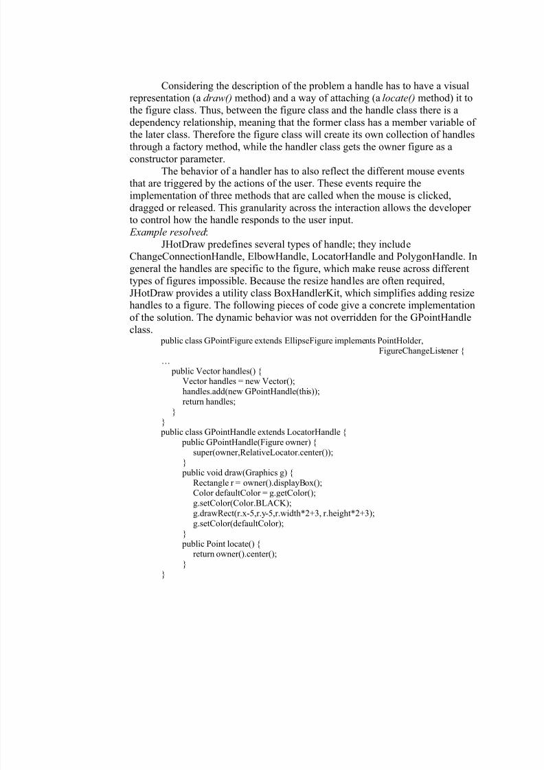
Example resolved :
JHotDraw predefines several types of handle; they includeChangeConnectionHandle, ElbowHandle, LocatorHandle and PolygonHandle. In
general the handles are specific to the figure, which make reuse across differenttypes of figures impossible. Because the resize handles are often required,
JHotDraw provides a utility class BoxHandlerKit, which simplifies adding resizehandles to a figure. The following pieces of code give a concrete implementation
of the solution. The dynamic behavior was not overridden for the GPointHandle
class. public class GPointFigure extends EllipseFigure implements PointHolder,
FigureChangeListener {
…
public Vector handles() {Vector handles = new Vector();
handles.add(new GPointHandle(this));
return handles;}
} public class GPointHandle extends LocatorHandle {
public GPointHandle(Figure owner) {
super(owner,RelativeLocator.center());}
public void draw(Graphics g) {
Rectangle r = owner().displayBox();Color defaultColor = g.getColor();
g.setColor(Color.BLACK);
g.drawRect(r.x-5,r.y-5,r.width*2+3, r.height*2+3);
g.setColor(defaultColor);
}
public Point locate() {return owner().center();
}
}
8/6/2019 Tanase Thesis
http://slidepdf.com/reader/full/tanase-thesis 53/85
Using an Alternative to Handlers Abstract :
This pattern explains how to implement visual components such as popup
menus, dialogs to support attribute-changing operations that cannot be
accomplished with the use of handles. Example:
The celestial bodies abstracted by the SolarSystemTool are characterized
by: mass, radius, color, position and velocity vectors. The application enables theuser to modify any of these values.
Context :
The programmer needs to define the appropriate visual way such that the properties of the figure are updated at run-time by user interaction.
Problem:
A handler changes one feature of a figure at a time, and the figures have alarge set of attributes that can be modified. Implementing handlers for every
single one becomes cumbersome and it scatters the information about the figure.The GUI is already designed or it is cluttered with other visual components
(panels, toolbars, buttons). The problem becomes to find a space saving way to letthe user choose which attribute he wants to alter. The appropriate implementation
for this problem should also reflect human preferences in terms of GUIs.Solution:
Considering the statement of the problem, the main issue that arises is to
attach a properties inspector to a figure such as a panel or a dialog window.
Depending on the implementation platform (Mac or PC) the programmer shoulddecide what particular mouse events (double-clicking for Mac or right mouse
click on a PC) will be captured. When double-clicking on a figure it will be
appropriate to have a dialog window showing up, while on a right mouse click acontext sensitive popup menu will be more approapriate.
From the pattern Changing the Attributes of a Figure it results that theeditor class keeps track of one tool to select and manipulate figures. This tool is in
one of three states: background selection, figure selection, and handle
manipulation. For capturing the mouse event the programmer will need to
customize the behavior of the selection tool. The dialog window or popup menuwill be invisible until the user makes a platform-specific mouse action. Thus the
space problem is overcome.
If using a popup menu the user will need to select from a list of options. Agood design will extract the code for the selection actions into command classes.
For example, if the application supports cut, copy or paste, the programmer willassociate them a CutCommand, CopyCommand, PasteCommand class. Refer tothe GoF book for the implementations details of the Command pattern.
If using a dialog window, the figure will be passed in its constructor.
Identifying the figure that was clicked is just a matter of invoking a find methodwith the coordinates given by the mouse event. The class that has the role of a
drawing canvas should be able to locate the figure. Thus, your dialog will
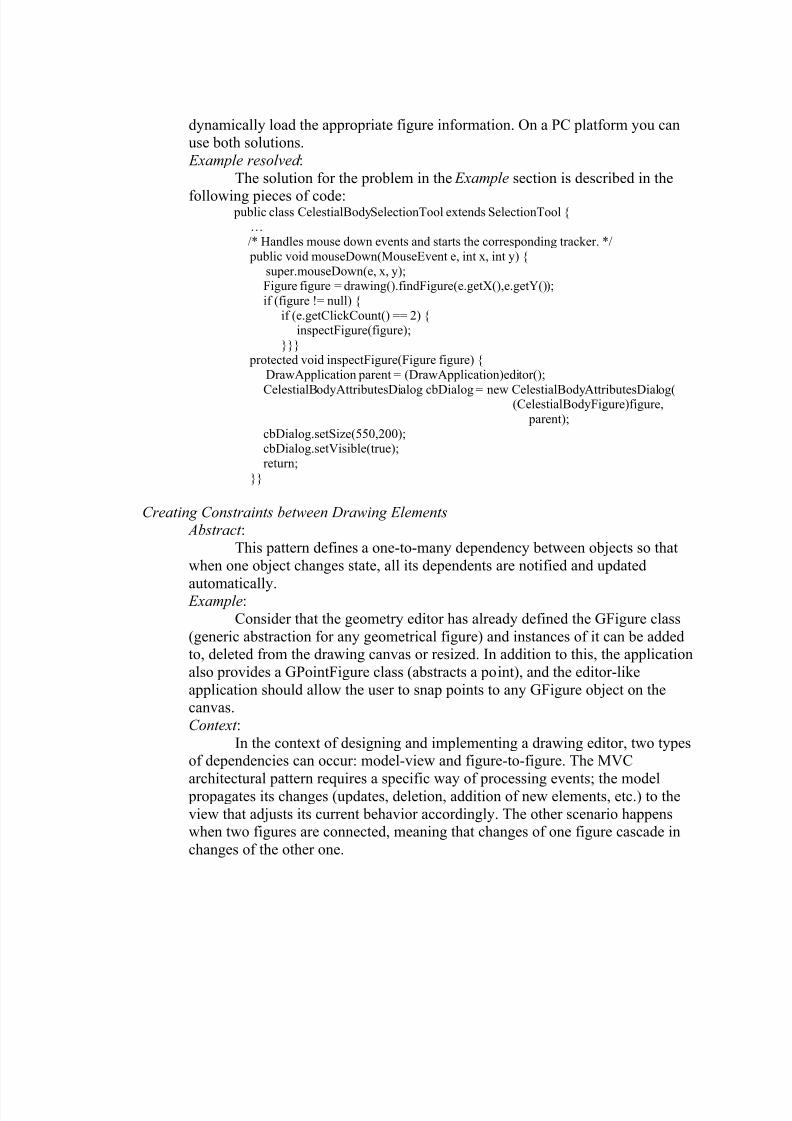
8/6/2019 Tanase Thesis
http://slidepdf.com/reader/full/tanase-thesis 54/85
dynamically load the appropriate figure information. On a PC platform you canuse both solutions.
Example resolved :
The solution for the problem in the Example section is described in the
following pieces of code: public class CelestialBodySelectionTool extends SelectionTool {
…
/* Handles mouse down events and starts the corresponding tracker. */
public void mouseDown(MouseEvent e, int x, int y) {
super.mouseDown(e, x, y);Figure figure = drawing().findFigure(e.getX(),e.getY());
if (figure != null) {
if (e.getClickCount() == 2) {inspectFigure(figure);
}}}
protected void inspectFigure(Figure figure) {
DrawApplication parent = (DrawApplication)editor();
CelestialBodyAttributesDialog cbDialog = new CelestialBodyAttributesDialog((CelestialBodyFigure)figure,
parent);
cbDialog.setSize(550,200);cbDialog.setVisible(true);
return;
}}
Creating Constraints between Drawing Elements Abstract :
This pattern defines a one-to-many dependency between objects so that
when one object changes state, all its dependents are notified and updated
automatically. Example:
Consider that the geometry editor has already defined the GFigure class
(generic abstraction for any geometrical figure) and instances of it can be addedto, deleted from the drawing canvas or resized. In addition to this, the application
also provides a GPointFigure class (abstracts a point), and the editor-like
application should allow the user to snap points to any GFigure object on thecanvas.
Context :
In the context of designing and implementing a drawing editor, two typesof dependencies can occur: model-view and figure-to-figure. The MVC
architectural pattern requires a specific way of processing events; the model propagates its changes (updates, deletion, addition of new elements, etc.) to the
view that adjusts its current behavior accordingly. The other scenario happenswhen two figures are connected, meaning that changes of one figure cascade in
changes of the other one.
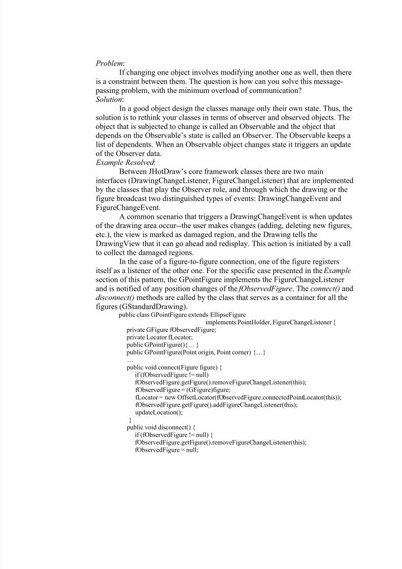
8/6/2019 Tanase Thesis
http://slidepdf.com/reader/full/tanase-thesis 55/85
Problem:
If changing one object involves modifying another one as well, then there
is a constraint between them. The question is how can you solve this message-
passing problem, with the minimum overload of communication?
Solution:In a good object design the classes manage only their own state. Thus, the
solution is to rethink your classes in terms of observer and observed objects. The
object that is subjected to change is called an Observable and the object thatdepends on the Observable’s state is called an Observer. The Observable keeps a
list of dependents. When an Observable object changes state it triggers an update
of the Observer data. Example Resolved :
Between JHotDraw’s core framework classes there are two main
interfaces (DrawingChangeListener, FigureChangeListener) that are implemented by the classes that play the Observer role, and through which the drawing or the
figure broadcast two distinguished types of events: DrawingChangeEvent andFigureChangeEvent.
A common scenario that triggers a DrawingChangeEvent is when updatesof the drawing area occur--the user makes changes (adding, deleting new figures,
etc.), the view is marked as damaged region, and the Drawing tells the
DrawingView that it can go ahead and redisplay. This action is initiated by a callto collect the damaged regions.
In the case of a figure-to-figure connection, one of the figure registers
itself as a listener of the other one. For the specific case presented in the Example
section of this pattern, the GPointFigure implements the FigureChangeListener
and is notified of any position changes of the fObservedFigure. The connect() and
disconnect() methods are called by the class that serves as a container for all thefigures (GStandardDrawing).
public class GPointFigure extends EllipseFigure
implements PointHolder, FigureChangeListener {
private GFigure fObservedFigure; private Locator fLocator;
public GPointFigure(){… }
public GPointFigure(Point origin, Point corner) {…}
…
public void connect(Figure figure) {if (fObservedFigure != null)
fObservedFigure.getFigure().removeFigureChangeListener(this);
fObservedFigure = (GFigure)figure;
fLocator = new OffsetLocator(fObservedFigure.connectedPointLocator(this));fObservedFigure.getFigure().addFigureChangeListener(this);
updateLocation();
} public void disconnect() {
if (fObservedFigure != null) {
fObservedFigure.getFigure().removeFigureChangeListener(this);
fObservedFigure = null;
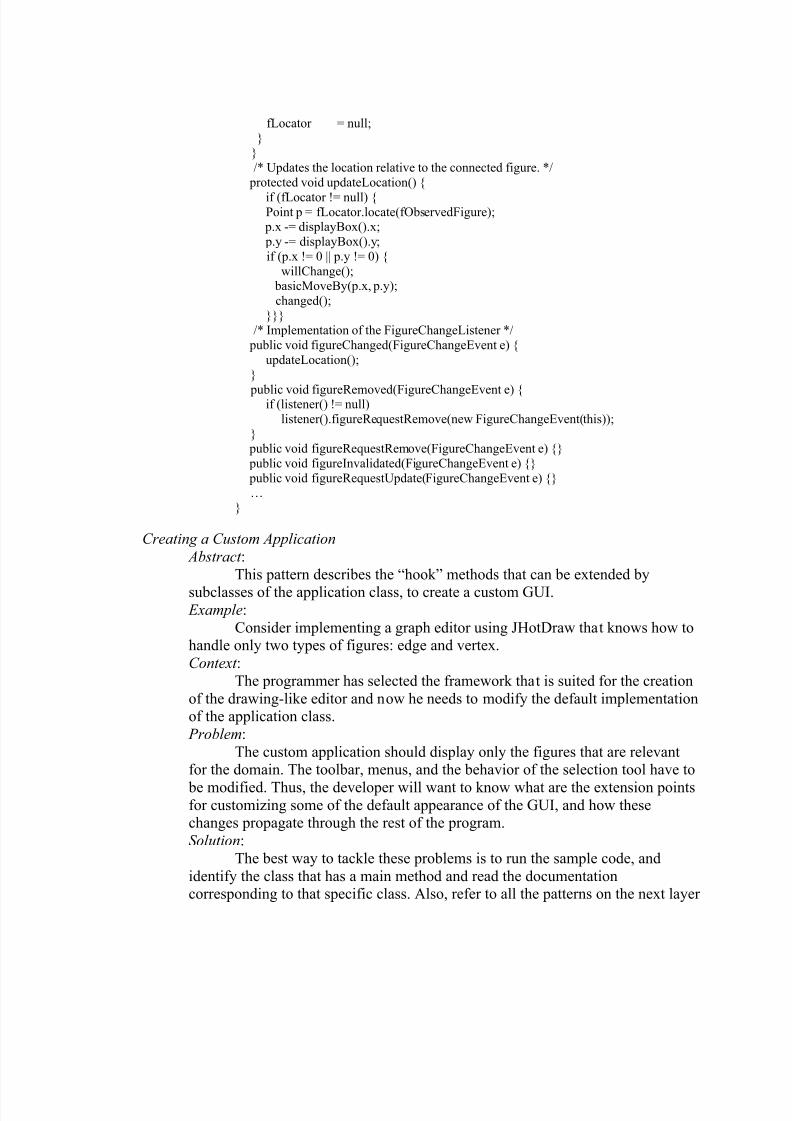
8/6/2019 Tanase Thesis
http://slidepdf.com/reader/full/tanase-thesis 56/85
fLocator = null;
}}
/* Updates the location relative to the connected figure. */
protected void updateLocation() {
if (fLocator != null) {Point p = fLocator.locate(fObservedFigure);
p.x -= displayBox().x;
p.y -= displayBox().y;
if (p.x != 0 || p.y != 0) {
willChange(); basicMoveBy(p.x, p.y);
changed();
}}}/* Implementation of the FigureChangeListener */
public void figureChanged(FigureChangeEvent e) {
updateLocation();
}
public void figureRemoved(FigureChangeEvent e) {if (listener() != null)
listener().figureRequestRemove(new FigureChangeEvent(this));
} public void figureRequestRemove(FigureChangeEvent e) {}
public void figureInvalidated(FigureChangeEvent e) {}
public void figureRequestUpdate(FigureChangeEvent e) {}…
}
Creating a Custom Application Abstract :
This pattern describes the “hook” methods that can be extended by
subclasses of the application class, to create a custom GUI. Example:
Consider implementing a graph editor using JHotDraw that knows how tohandle only two types of figures: edge and vertex.
Context : The programmer has selected the framework that is suited for the creation
of the drawing-like editor and now he needs to modify the default implementationof the application class.
Problem:
The custom application should display only the figures that are relevantfor the domain. The toolbar, menus, and the behavior of the selection tool have to
be modified. Thus, the developer will want to know what are the extension pointsfor customizing some of the default appearance of the GUI, and how thesechanges propagate through the rest of the program.
Solution: The best way to tackle these problems is to run the sample code, and
identify the class that has a main method and read the documentationcorresponding to that specific class. Also, refer to all the patterns on the next layer
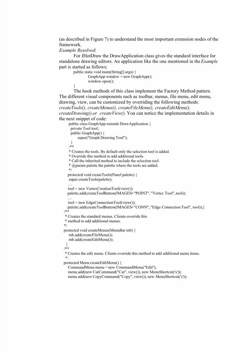
8/6/2019 Tanase Thesis
http://slidepdf.com/reader/full/tanase-thesis 57/85
(as described in Figure 7) to understand the most important extension nodes of theframework.
Example Resolved :
For JHotDraw the DrawApplication class gives the standard interface for
standalone drawing editors. An application like the one mentioned in the Example part is started as follows:
public static void main(String[] args) {
GraphApp window = new GraphApp();
window.open();
}
The hook methods of this class implement the Factory Method pattern.The different visual components such as toolbar, menus, file menu, edit menu,
drawing, view, can be customized by overriding the following methods:
createTools(), createMenus(), createFileMenu(), createEditMenu(),createDrawing(),or createView(). You can notice the implementation details in
the next snippet of code:
public class GraphApp extends DrawApplication { private Tool tool;
public GraphApp() {super("Graph Drawing Tool");
}
/**
* Creates the tools. By default only the selection tool is added.
* Override this method to add additional tools.* Call the inherited method to include the selection tool.
* @param palette the palette where the tools are added.
*/
protected void createTools(Panel palette) {super.createTools(palette);
…tool = new VertexCreationTool(view());
palette.add(createToolButton(IMAGES+"POINT", "Vertex Tool", tool));
…
tool = new EdgeConnectionTool(view());
palette.add(createToolButton(IMAGES+"CONN", "Edge Connection Tool", tool));}/**
* Creates the standard menus. Clients override this
* method to add additional menus.
*/ protected void createMenus(MenuBar mb) {
mb.add(createFileMenu());
mb.add(createEditMenu());
}/**
* Creates the edit menu. Clients override this method to add additional menu items.
*/
protected Menu createEditMenu() {CommandMenu menu = new CommandMenu("Edit");
menu.add(new CutCommand("Cut", view()), new MenuShortcut('x'));
menu.add(new CopyCommand("Copy", view()), new MenuShortcut('c'));
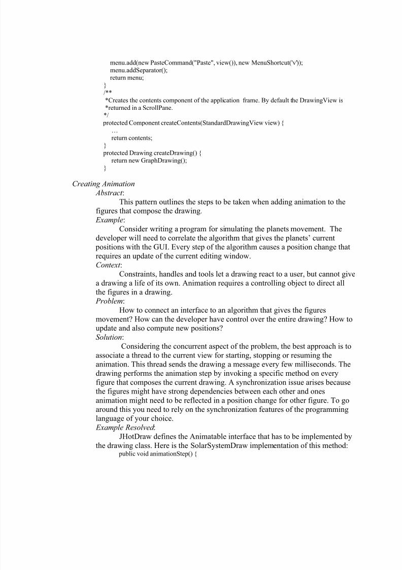
8/6/2019 Tanase Thesis
http://slidepdf.com/reader/full/tanase-thesis 58/85
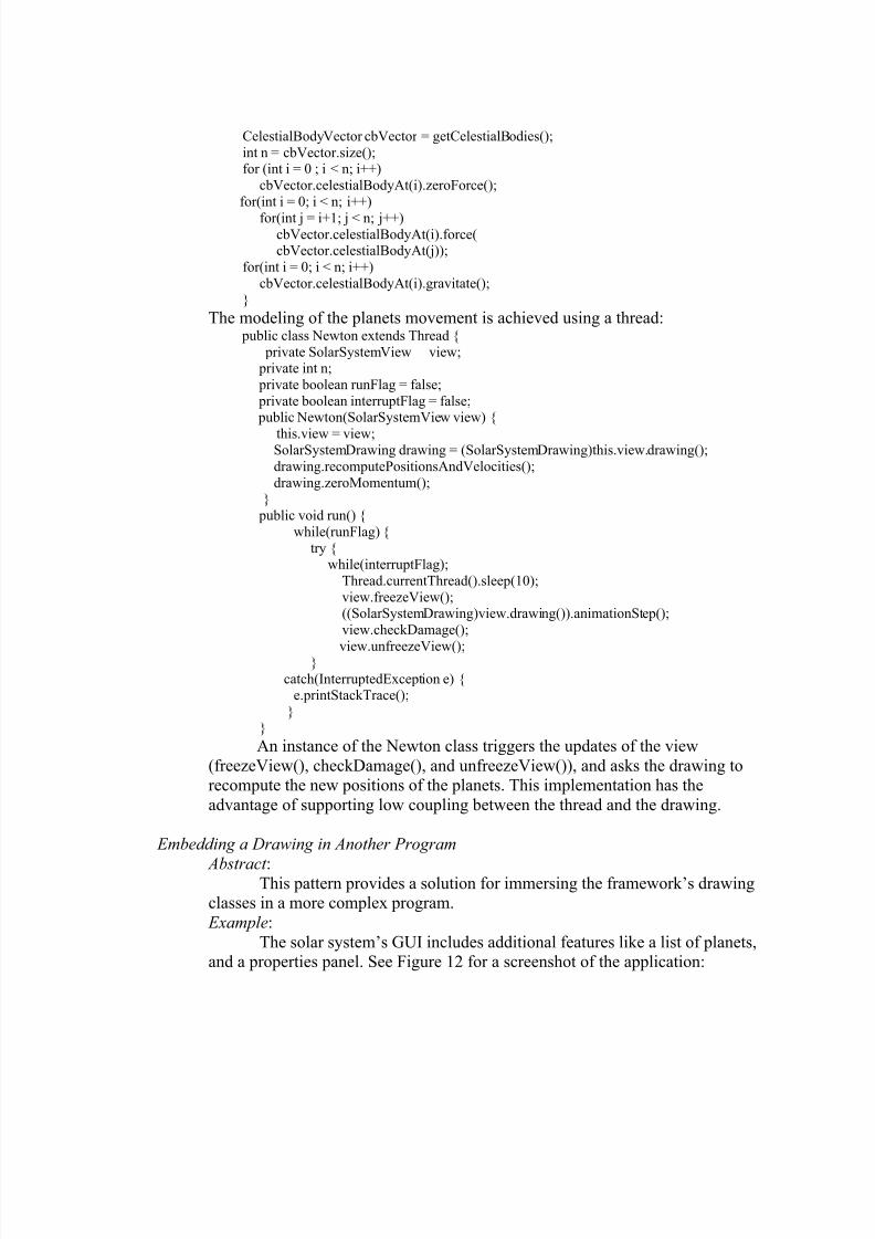
8/6/2019 Tanase Thesis
http://slidepdf.com/reader/full/tanase-thesis 59/85
CelestialBodyVector cbVector = getCelestialBodies();
int n = cbVector.size();for (int i = 0 ; i < n; i++)
cbVector.celestialBodyAt(i).zeroForce();
for(int i = 0; i < n; i++)
for(int j = i+1; j < n; j++)cbVector.celestialBodyAt(i).force(cbVector.celestialBodyAt(j));
for(int i = 0; i < n; i++)
cbVector.celestialBodyAt(i).gravitate();
}
The modeling of the planets movement is achieved using a thread: public class Newton extends Thread {
private SolarSystemView view; private int n;
private boolean runFlag = false;
private boolean interruptFlag = false; public Newton(SolarSystemView view) {
this.view = view;SolarSystemDrawing drawing = (SolarSystemDrawing)this.view.drawing();
drawing.recomputePositionsAndVelocities();
drawing.zeroMomentum();}
public void run() {
while(runFlag) {
try {while(interruptFlag);
Thread.currentThread().sleep(10);
view.freezeView();((SolarSystemDrawing)view.drawing()).animationStep();
view.checkDamage();
view.unfreezeView();}
catch(InterruptedException e) {e.printStackTrace();
}
}
An instance of the Newton class triggers the updates of the view
(freezeView(), checkDamage(), and unfreezeView()), and asks the drawing torecompute the new positions of the planets. This implementation has the
advantage of supporting low coupling between the thread and the drawing.
Embedding a Drawing in Another Program
Abstract :This pattern provides a solution for immersing the framework’s drawing
classes in a more complex program.
Example:
The solar system’s GUI includes additional features like a list of planets,and a properties panel. See Figure 12 for a screenshot of the application:
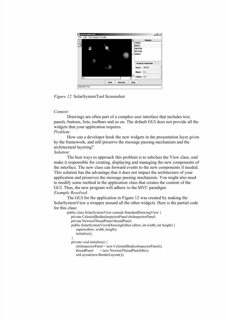
8/6/2019 Tanase Thesis
http://slidepdf.com/reader/full/tanase-thesis 60/85
Figure 12. SolarSystemTool Screenshot.
Context :Drawings are often part of a complex user interface that includes text,
panels, buttons, lists, toolbars and so on. The default GUI does not provide all thewidgets that your application requires. Problem:
How can a developer hook the new widgets in the presentation layer given by the framework, and still preserve the message passing mechanism and the
architectural layering?Solution:
The best ways to approach this problem is to subclass the View class, and
make it responsible for creating, displaying and managing the new components of
the interface. The new class can forward events to the new components if needed.This solution has the advantage that it does not impact the architecture of your
application and preserves the message passing mechanism. You might also needto modify some method in the application class that creates the content of the
GUI. Thus, the new program will adhere to the MVC paradigm. Example Resolved :
The GUI for the application in Figure 12 was created by making theSolarSystemView a wrapper around all the other widgets. Here is the partial code
for this class: public class SolarSystemView extends StandardDrawingView {
private CelestialBodiesInspectorPanel cbsInspectorPanel;
private NewtonThreadPanel threadPanel;
public SolarSystemView(DrawingEditor editor, int width, int height) {super(editor, width, height);
initialize();
} private void initialize() {
cbsInspectorPanel = new CelestialBodiesInspectorPanel();
threadPanel = new NewtonThreadPanel(this);
setLayout(new BorderLayout());
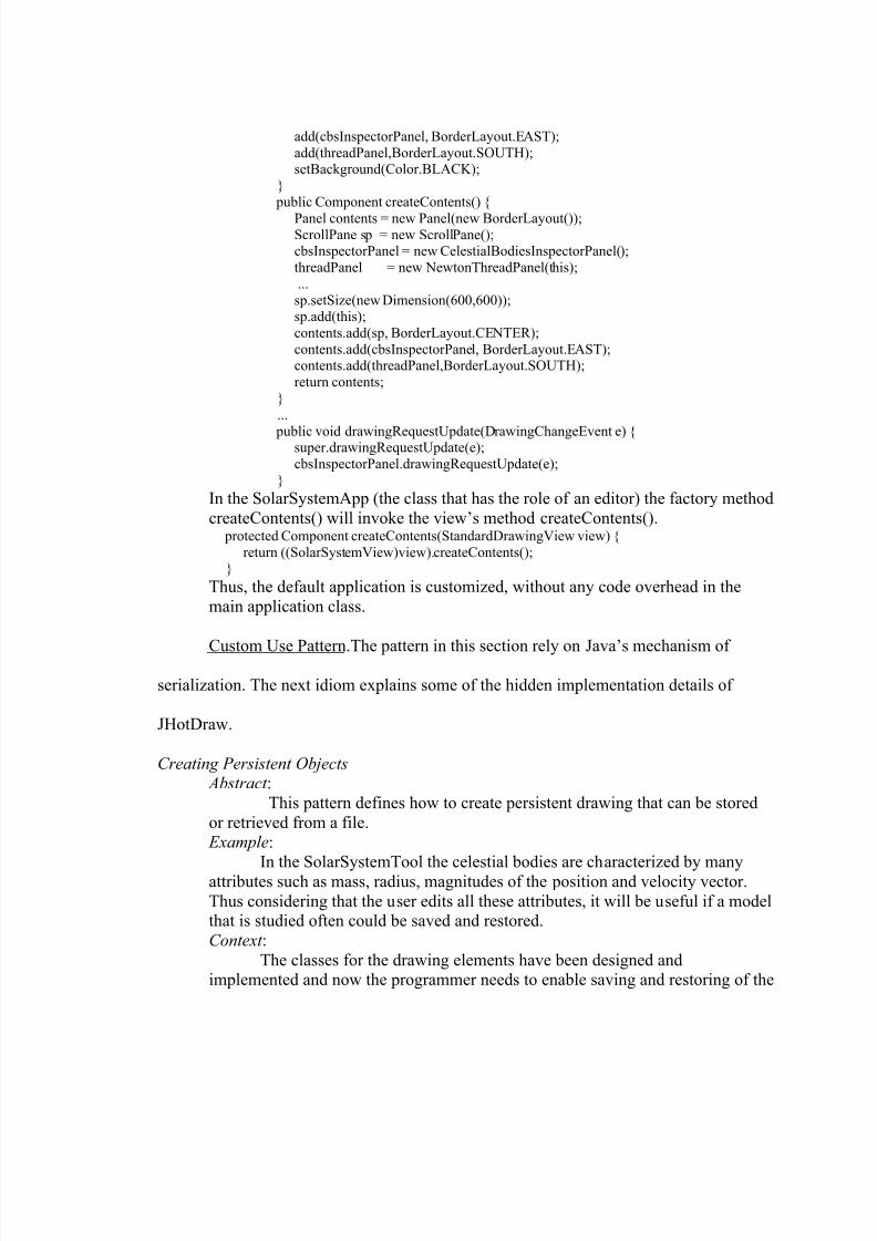
8/6/2019 Tanase Thesis
http://slidepdf.com/reader/full/tanase-thesis 61/85
add(cbsInspectorPanel, BorderLayout.EAST);
add(threadPanel,BorderLayout.SOUTH);setBackground(Color.BLACK);
}
public Component createContents() {
Panel contents = new Panel(new BorderLayout());ScrollPane sp = new ScrollPane();cbsInspectorPanel = new CelestialBodiesInspectorPanel();
threadPanel = new NewtonThreadPanel(this);
...
sp.setSize(new Dimension(600,600));sp.add(this);
contents.add(sp, BorderLayout.CENTER);
contents.add(cbsInspectorPanel, BorderLayout.EAST);contents.add(threadPanel,BorderLayout.SOUTH);
return contents;
}
...
public void drawingRequestUpdate(DrawingChangeEvent e) {super.drawingRequestUpdate(e);
cbsInspectorPanel.drawingRequestUpdate(e);
}
In the SolarSystemApp (the class that has the role of an editor) the factory method
createContents() will invoke the view’s method createContents(). protected Component createContents(StandardDrawingView view) {
return ((SolarSystemView)view).createContents();}
Thus, the default application is customized, without any code overhead in the
main application class.
Custom Use Pattern.The pattern in this section rely on Java’s mechanism of
serialization. The next idiom explains some of the hidden implementation details of
JHotDraw.
Creating Persistent Objects Abstract :
This pattern defines how to create persistent drawing that can be stored
or retrieved from a file.
Example:
In the SolarSystemTool the celestial bodies are characterized by manyattributes such as mass, radius, magnitudes of the position and velocity vector.
Thus considering that the user edits all these attributes, it will be useful if a modelthat is studied often could be saved and restored.
Context :
The classes for the drawing elements have been designed andimplemented and now the programmer needs to enable saving and restoring of the
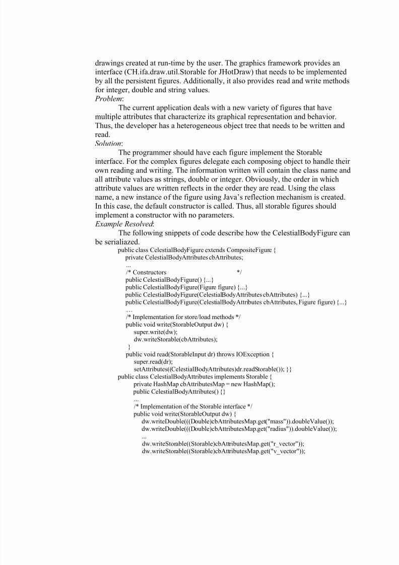
8/6/2019 Tanase Thesis
http://slidepdf.com/reader/full/tanase-thesis 62/85
drawings created at run-time by the user. The graphics framework provides aninterface (CH.ifa.draw.util.Storable for JHotDraw) that needs to be implemented
by all the persistent figures. Additionally, it also provides read and write methods
for integer, double and string values.
Problem: The current application deals with a new variety of figures that have
multiple attributes that characterize its graphical representation and behavior.
Thus, the developer has a heterogeneous object tree that needs to be written andread.
Solution:
The programmer should have each figure implement the Storableinterface. For the complex figures delegate each composing object to handle their
own reading and writing. The information written will contain the class name and
all attribute values as strings, double or integer. Obviously, the order in whichattribute values are written reflects in the order they are read. Using the class
name, a new instance of the figure using Java’s reflection mechanism is created.In this case, the default constructor is called. Thus, all storable figures should
implement a constructor with no parameters. Example Resolved :
The following snippets of code describe how the CelestialBodyFigure can
be serialiazed. public class CelestialBodyFigure extends CompositeFigure {
private CelestialBodyAttributes cbAttributes;
...
/* Constructors */ public CelestialBodyFigure() {...}
public CelestialBodyFigure(Figure figure) {...}
public CelestialBodyFigure(CelestialBodyAttributes cbAttributes) {...} public CelestialBodyFigure(CelestialBodyAttributes cbAttributes, Figure figure) {...}
…/* Implementation for store/load methods */
public void write(StorableOutput dw) {
super.write(dw);dw.writeStorable(cbAttributes);
}
public void read(StorableInput dr) throws IOException {super.read(dr);
setAttributes((CelestialBodyAttributes)dr.readStorable()); }}
public class CelestialBodyAttributes implements Storable {
private HashMap cbAttributesMap = new HashMap();
public CelestialBodyAttributes() {}
.../* Implementation of the Storable interface */
public void write(StorableOutput dw) {
dw.writeDouble(((Double)cbAttributesMap.get("mass")).doubleValue());dw.writeDouble(((Double)cbAttributesMap.get("radius")).doubleValue());
...
dw.writeStorable((Storable)cbAttributesMap.get("r_vector"));dw.writeStorable((Storable)cbAttributesMap.get("v_vector"));

8/6/2019 Tanase Thesis
http://slidepdf.com/reader/full/tanase-thesis 63/85
}
public void read(StorableInput dr) throws IOException {cbAttributesMap.put("mass", new Double(dr.readDouble()));
cbAttributesMap.put("radius", new Double(dr.readDouble()));
...
cbAttributesMap.put("r_vector",(PositionVector)dr.readStorable());cbAttributesMap.put("v_vector",(PositionVector)dr.readStorable());
}
}
With this pattern the description of this seminal pattern language for documenting
JHotDraw is concluded. As mentioned in the first section of this chapter, a pattern
language is derived after many interations, but this set of patterns covers only partially
the scope of the framework. The following chapters provide ideas on how to extend or
refine the existing set. The final goal is to obtain a set that acts as a generator for any kind
of application that instantiates JHotDraw.
8/6/2019 Tanase Thesis
http://slidepdf.com/reader/full/tanase-thesis 64/85
CHAPTER 4
A CRITICAL VIEW OF THE JHOTDRAW PATTERN LANGUAGE
A complete assessment of a pattern language requires an elaborate empirical
evaluation of expert practitioners who have applied the language. This would enable a
statistically valid conclusion to be drawn about the language, but such an endeavor is out
of the scope of this thesis.
Therefore this chapter’s focus is on the forces that acted upon the writing process.
The structure and content of the pattern language for documenting JHotDraw were built
in two stages: individual pattern writing ( Patterns for JHotDraw) and pattern
organization into a consistent, cohesive set ( Pattern language evolution). This
introspection concludes with a series of interrogations on the characteristics of the
JHotDraw language as well as its relationship with the framework ( Reflections about
pattern languages and frameworks).
Patterns for JHotDraw
Software patterns undergo a number of transformations until they reach a stable
form with respect to content and documenting style. The pattern community does not
impose compliance to any standard, but it expects that any written description that aspires
to the status of pattern encloses a problem description, a scenario when that particular
problem occurs (context), and a way to overcome it (solution).
The JHotDraw’s pattern descriptions are organized in the following sections:
Pattern Name, Problem, Context, Solution, Example, Example Resolved, and Abstract.
The first four are mandatory for a pattern specification because they cover the necessary
8/6/2019 Tanase Thesis
http://slidepdf.com/reader/full/tanase-thesis 65/85
information for understanding the three-part rule (context-problem-solution) that
characterizes the semantics of the pattern. The rest of the information regarding
implementation details or concrete problems and solutions, is embedded in the Example
and Example Resolved sections. These cannot be directly used in an application--they
need to be adapted to suit the problem. They are useful, because they provide a concrete
illustration of the context-problem-solution, but not essential for understanding the
patterns. The Abstract section enables the readers to quickly skim through the set of
pattern and identify the appropriate one for their problem (Meszaros & Doble, 2003).
Adopting this structure provides the template that needs to be applied in the
pattern writing process. It also helps preserve consistency of form while writing other
patterns. This is valuable because it makes the pattern language coherent and therefore
easier to read. The next steps are generating the content and correctly separating it into
the corresponding sections.
The Creating a Drawing Element pattern will be used as an example to illustrate
the forces exerted when composing a description. This pattern refines the Defining
Drawing Elements pattern by Johnson (1992) and has the following problem statement:
“There are an infinite variety of primitive figures that can be included in a drawing. Thus,
there needs to be a way to make new figures for each application.” In the context of
pattern relationships “X refines Y” is equivalent to saying that the scope (problem-
context) of Y is included in the scope of X.
The usual lifecycle of a pattern is characterized by four main phases: recognition
(witness the pattern occurrences), conceptualization (envisioning the pattern from several
8/6/2019 Tanase Thesis
http://slidepdf.com/reader/full/tanase-thesis 66/85
similar contexts), writing documentation, and dissemination to other practitioners.
Because Creating a Drawing Element has its genesis in JHotDraw’s pattern catalogue,
the first phase of the lifecycle can be skipped.
In order to be able to redefine this pattern, it was necessary to implement a test
program, which could instantiate Johnson’s pattern. The first application derived from
JHotDraw was a simple editor for geometrical figures. This was intended to be a
sketchpad for solving geometry problems, but that proved to be an endeavor that went
beyond the scope of this research.
As a starting point for this program I used the sample source code for the
CH.ifa.draw.samples.nothing class. To add functionality to this application, the main
issue was to create a class that abstracts different geometrical figures such as rectangle,
ellipse, line, triangle, and diamond. In addition to that, any polygon can be named (points
can be connected to the figure and named), moved and resized using the mouse. Though
the framework provided a variety of primitive elements their default behavior did not
match the requirements of the geometry editor. Rewriting completely each of the figure
classes (e.g., RectangleFigure, EllipseFigure, etc.) would generate a new library of shapes
and defeat the purpose of using JHotDraw. This problem appears to be an instantiation of
the Defining Drawing Elements problem. Thus, following the description of this pattern
provided guidelines for implementing a new figure.
The drawback to Johnson’s pattern is its monolithic form (abstract and context-
problem-forces-solution) that makes it difficult to determine all the different
responsibilities of a drawing element and the sequence in which they need to be
8/6/2019 Tanase Thesis
http://slidepdf.com/reader/full/tanase-thesis 67/85
implemented. The solution given by this pattern, however, drew attention to other
subsequent problems such as composing drawing elements, changing their attributes,
creating constraints between them, and using tools. Solutions to these subproblems
coalesced as patterns later, after I developed other test programs. The seeds for those
patterns already existed in Johnson’s article on Documenting Frameworks using Pattern
Languages (refer to Figure 6 in Chapter 2, for an overview of the language).
The conceptualization phase of the Creating a Drawing Element pattern was
initiated once all its subproblems were identified, but the documenting phase had to be
postponed until each of its nested problems had been solved. Thus, when the description
of Composing Drawing Elements, Changing the Attributes of a Drawing Element ,
Creating Constraints between Drawing Elements and Using a Creation Tool was
finalized, the life thread of the initial pattern was resumed.
After finishing the documentation of the pattern, the dissemination phase follows.
This stage has two components: internal and external dissemination. Internal
dissemination refers to any implementations where I tested the patterns, while external
dissemination is accomplished by releasing the entire pattern language, summarized in
Table 13, to the JHotDraw developers community.
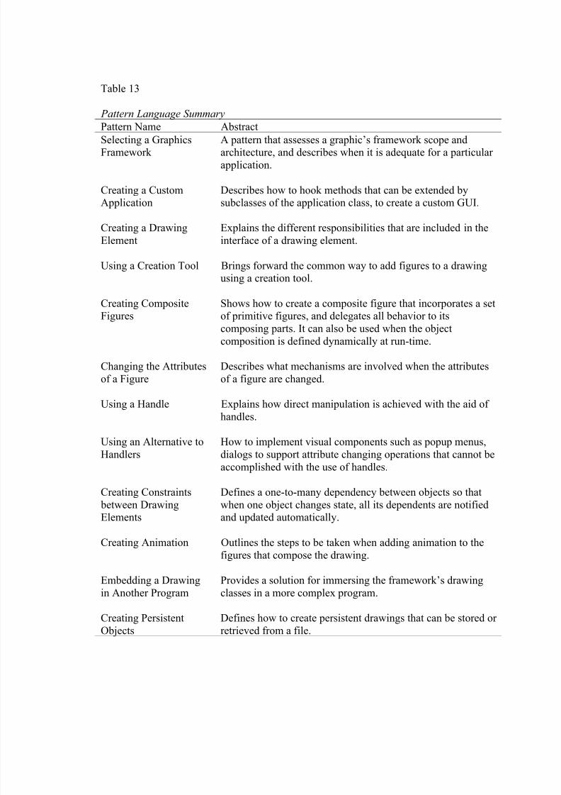
8/6/2019 Tanase Thesis
http://slidepdf.com/reader/full/tanase-thesis 68/85
Table 13
Pattern Language Summary
Pattern Name Abstract
Selecting a GraphicsFramework
A pattern that assesses a graphic’s framework scope andarchitecture, and describes when it is adequate for a particular
application.
Creating a CustomApplication
Describes how to hook methods that can be extended bysubclasses of the application class, to create a custom GUI.
Creating a Drawing
Element
Explains the different responsibilities that are included in the
interface of a drawing element.
Using a Creation Tool Brings forward the common way to add figures to a drawing
using a creation tool.
Creating CompositeFigures
Shows how to create a composite figure that incorporates a setof primitive figures, and delegates all behavior to its
composing parts. It can also be used when the object
composition is defined dynamically at run-time.
Changing the Attributes
of a Figure
Describes what mechanisms are involved when the attributes
of a figure are changed.
Using a Handle Explains how direct manipulation is achieved with the aid of
handles.
Using an Alternative to
Handlers
How to implement visual components such as popup menus,
dialogs to support attribute changing operations that cannot be
accomplished with the use of handles.
Creating Constraints
between DrawingElements
Defines a one-to-many dependency between objects so that
when one object changes state, all its dependents are notifiedand updated automatically.
Creating Animation Outlines the steps to be taken when adding animation to the
figures that compose the drawing.
Embedding a Drawing
in Another Program
Provides a solution for immersing the framework’s drawing
classes in a more complex program.
Creating Persistent
Objects
Defines how to create persistent drawings that can be stored or
retrieved from a file.
8/6/2019 Tanase Thesis
http://slidepdf.com/reader/full/tanase-thesis 69/85
Gathering feedback from the community helps improve on the content of the pattern. In
the end, others testimonies that these patterns can contribute to successful software
practice marks the completion of the lifecycle for a pattern.
Table 13 shows that the JHotDraw pattern language offers a base of patterns to
start building a variety of software systems. But, attempting to derive an application only
using only these patterns will point out its incompleteness and the need for fine-grained
(more specific) patterns. This language can be used as a complementary tool to the
already existing documentation, when for instantiating the JHotDraw framework.
Pattern Language Evolution
The JHotDraw pattern language arises from two distinguished needs: as a way of
understanding and possibly controlling, the complexity of the framework, and as a
necessary design tool with which to build programs that are functionally and structurally
coherent (Salingaros, 2000). Its growth in time tried to balance both of these aspects. This
section presents the evolution of JHotDraw’s pattern language according to Alexander’s
algorithm as well as the subtle relationship with the framework’s transformation over
time.
As previously mentioned the JHotDraw pattern language relies on different
practitioners experiences, starting with those who used the Smalltalk version of HotDraw
(Johnson, 1992). The first step required assembling a group of patterns from a pattern
catalogue and developing new patterns for related processes that were left out initially.
(Salingaros, 2000) Thus, the evolution process began by selecting patterns from
Johnson’s (1992) pattern language written for the Smalltalk version of HotDraw. The
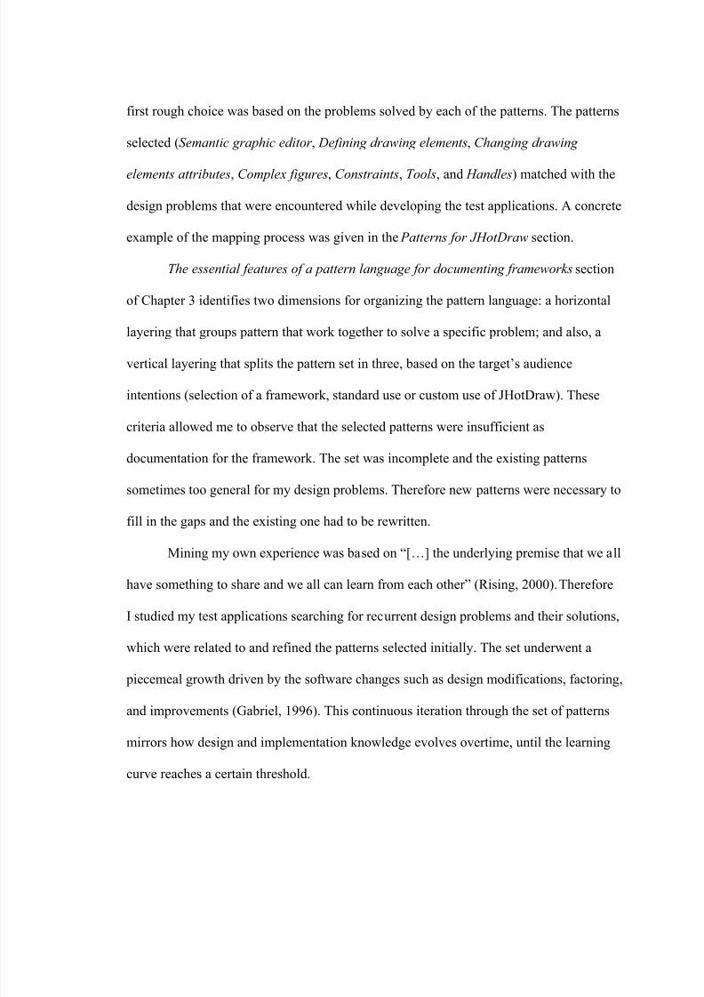
8/6/2019 Tanase Thesis
http://slidepdf.com/reader/full/tanase-thesis 70/85
first rough choice was based on the problems solved by each of the patterns. The patterns
selected (Semantic graphic editor , Defining drawing elements, Changing drawing
elements attributes, Complex figures, Constraints, Tools, and Handles) matched with the
design problems that were encountered while developing the test applications. A concrete
example of the mapping process was given in the Patterns for JHotDraw section.
The essential features of a pattern language for documenting frameworks section
of Chapter 3 identifies two dimensions for organizing the pattern language: a horizontal
layering that groups pattern that work together to solve a specific problem; and also, a
vertical layering that splits the pattern set in three, based on the target’s audience
intentions (selection of a framework, standard use or custom use of JHotDraw). These
criteria allowed me to observe that the selected patterns were insufficient as
documentation for the framework. The set was incomplete and the existing patterns
sometimes too general for my design problems. Therefore new patterns were necessary to
fill in the gaps and the existing one had to be rewritten.
Mining my own experience was based on “[…] the underlying premise that we all
have something to share and we all can learn from each other” (Rising, 2000). Therefore
I studied my test applications searching for recurrent design problems and their solutions,
which were related to and refined the patterns selected initially. The set underwent a
piecemeal growth driven by the software changes such as design modifications, factoring,
and improvements (Gabriel, 1996). This continuous iteration through the set of patterns
mirrors how design and implementation knowledge evolves overtime, until the learning
curve reaches a certain threshold.
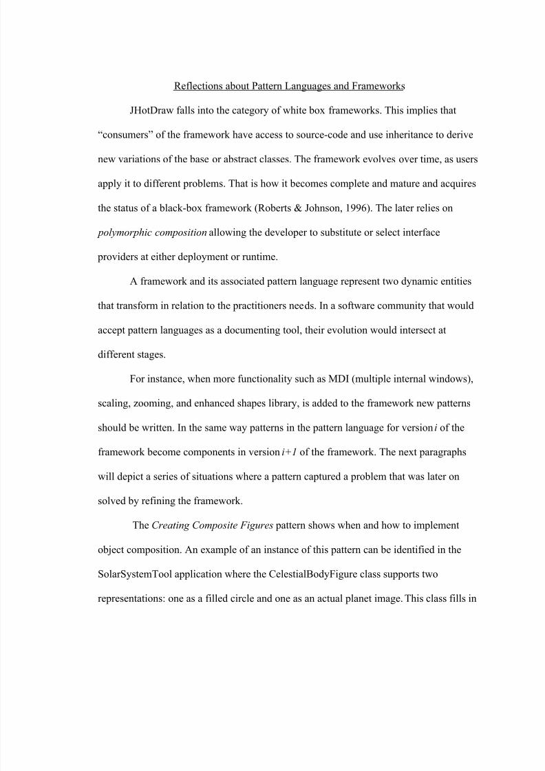
8/6/2019 Tanase Thesis
http://slidepdf.com/reader/full/tanase-thesis 71/85
Reflections about Pattern Languages and Frameworks
JHotDraw falls into the category of white box frameworks. This implies that
“consumers” of the framework have access to source-code and use inheritance to derive
new variations of the base or abstract classes. The framework evolves over time, as users
apply it to different problems. That is how it becomes complete and mature and acquires
the status of a black-box framework (Roberts & Johnson, 1996). The later relies on
polymorphic composition allowing the developer to substitute or select interface
providers at either deployment or runtime.
A framework and its associated pattern language represent two dynamic entities
that transform in relation to the practitioners needs. In a software community that would
accept pattern languages as a documenting tool, their evolution would intersect at
different stages.
For instance, when more functionality such as MDI (multiple internal windows),
scaling, zooming, and enhanced shapes library, is added to the framework new patterns
should be written. In the same way patterns in the pattern language for version i of the
framework become components in version i+1 of the framework. The next paragraphs
will depict a series of situations where a pattern captured a problem that was later on
solved by refining the framework.
The Creating Composite Figures pattern shows when and how to implement
object composition. An example of an instance of this pattern can be identified in the
SolarSystemTool application where the CelestialBodyFigure class supports two
representations: one as a filled circle and one as an actual planet image. This class fills in
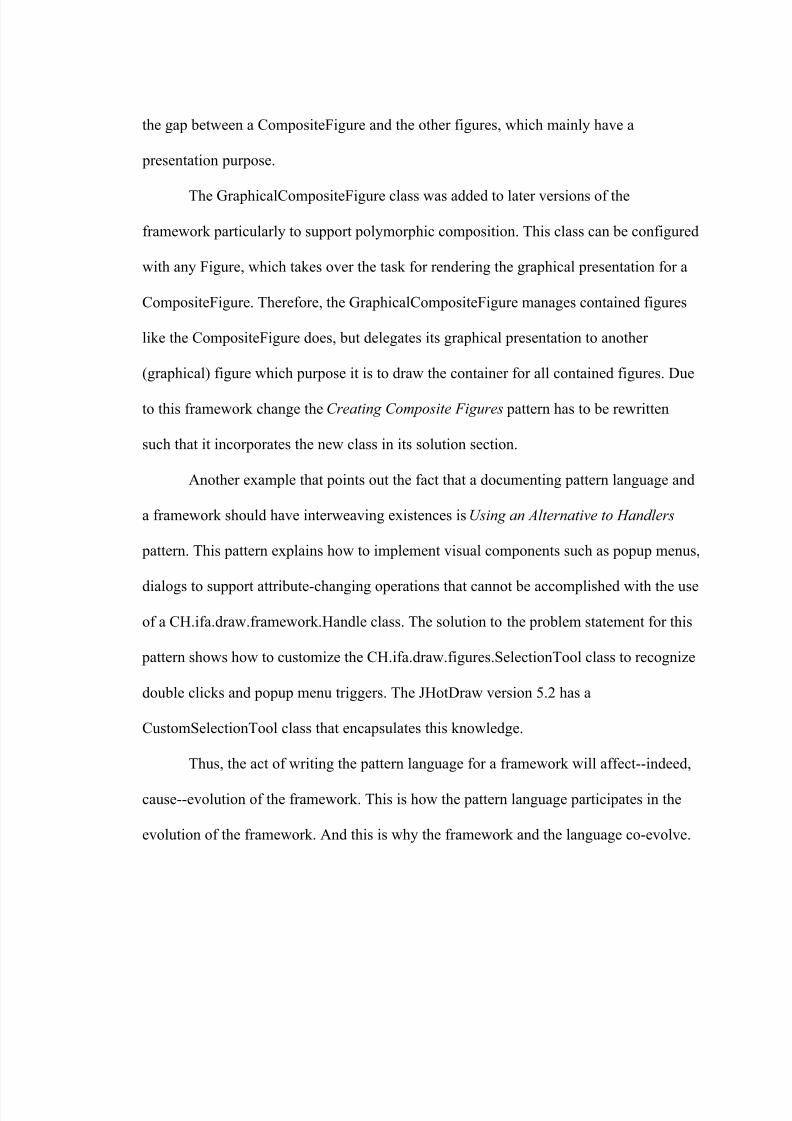
8/6/2019 Tanase Thesis
http://slidepdf.com/reader/full/tanase-thesis 72/85
the gap between a CompositeFigure and the other figures, which mainly have a
presentation purpose.
The GraphicalCompositeFigure class was added to later versions of the
framework particularly to support polymorphic composition. This class can be configured
with any Figure, which takes over the task for rendering the graphical presentation for a
CompositeFigure. Therefore, the GraphicalCompositeFigure manages contained figures
like the CompositeFigure does, but delegates its graphical presentation to another
(graphical) figure which purpose it is to draw the container for all contained figures. Due
to this framework change the Creating Composite Figures pattern has to be rewritten
such that it incorporates the new class in its solution section.
Another example that points out the fact that a documenting pattern language and
a framework should have interweaving existences is Using an Alternative to Handlers
pattern. This pattern explains how to implement visual components such as popup menus,
dialogs to support attribute-changing operations that cannot be accomplished with the use
of a CH.ifa.draw.framework.Handle class. The solution to the problem statement for this
pattern shows how to customize the CH.ifa.draw.figures.SelectionTool class to recognize
double clicks and popup menu triggers. The JHotDraw version 5.2 has a
CustomSelectionTool class that encapsulates this knowledge.
Thus, the act of writing the pattern language for a framework will affect--indeed,
cause--evolution of the framework. This is how the pattern language participates in the
evolution of the framework. And this is why the framework and the language co-evolve.
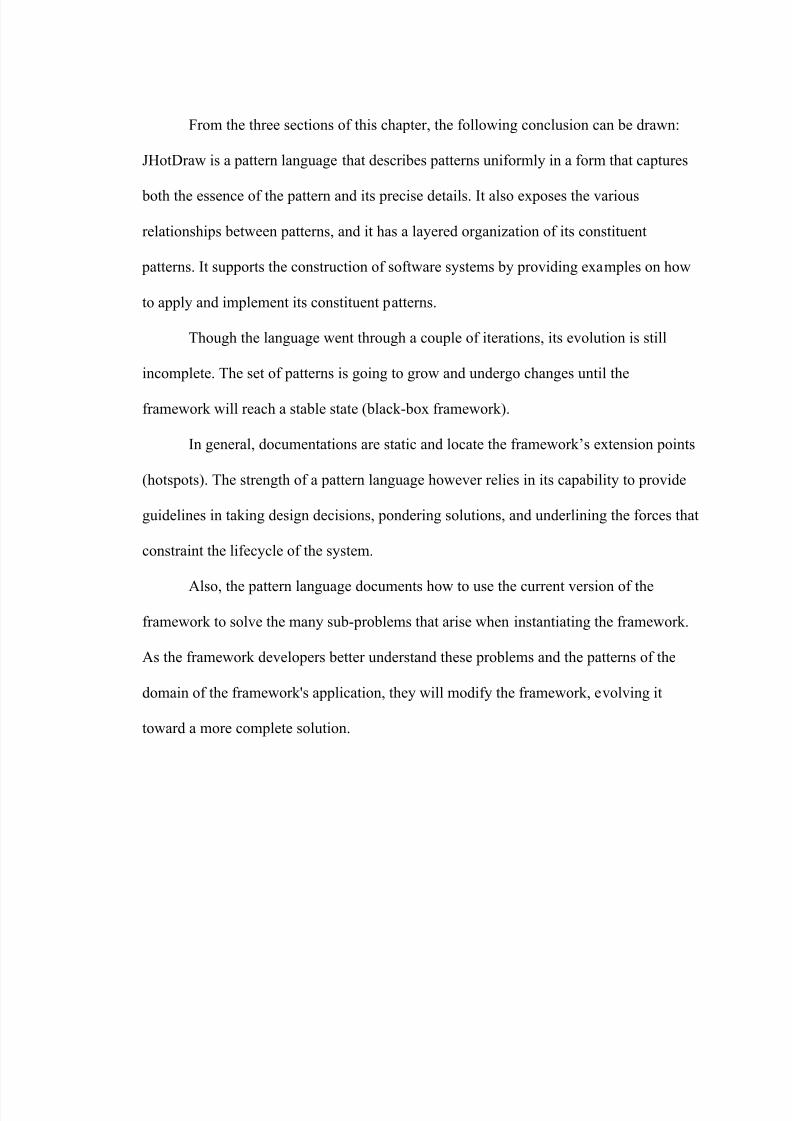
8/6/2019 Tanase Thesis
http://slidepdf.com/reader/full/tanase-thesis 73/85
From the three sections of this chapter, the following conclusion can be drawn:
JHotDraw is a pattern language that describes patterns uniformly in a form that captures
both the essence of the pattern and its precise details. It also exposes the various
relationships between patterns, and it has a layered organization of its constituent
patterns. It supports the construction of software systems by providing examples on how
to apply and implement its constituent patterns.
Though the language went through a couple of iterations, its evolution is still
incomplete. The set of patterns is going to grow and undergo changes until the
framework will reach a stable state (black-box framework).
In general, documentations are static and locate the framework’s extension points
(hotspots). The strength of a pattern language however relies in its capability to provide
guidelines in taking design decisions, pondering solutions, and underlining the forces that
constraint the lifecycle of the system.
Also, the pattern language documents how to use the current version of the
framework to solve the many sub-problems that arise when instantiating the framework.
As the framework developers better understand these problems and the patterns of the
domain of the framework's application, they will modify the framework, evolving it
toward a more complete solution.
8/6/2019 Tanase Thesis
http://slidepdf.com/reader/full/tanase-thesis 74/85
CHAPTER 5
CONCLUDING IDEAS ON WRITING A PATTERN LANGUAGE
The overview of the main ideas and concepts on patterns, pattern languages and
frameworks, from Chapter 1 and Chapter 2, the description of the pattern language for
documenting JHotDraw from Chapter 3, and the assessment of the language in Chapter 4
show that writing a pattern language is a demanding task. Now, what remains to be
shown is that for such an endeavor the pros counterbalance the cons.
Discussion of the Benefits and Drawbacks of a Pattern Language
Standard framework documentation is structured around the components of the
framework. Sample applications give an endpoint of application, not the process of
building an application. Pattern-based documentations are structured around components
of solutions and give the reasoning that leads to these solutions. This type of
documentation allows the programmer to think about the domain problem, not the little
details of making connections between classes. For example, a pattern language will
address questions as “Should I use inheritance or composition”?
A documentation that is easy to use has to be logically traceable and
comprehensible. Documenting a framework is complicated because the embedded
information has a substantial impact on its success as a reusable component and
implicitly affects the overall quality of the software systems that result from extending it.
The preparation of these documents requires enormous effort, and in the end there are no
certainties that the necessary information was captured such that practitioners are able to
trace it or understand it (Meusel et al., 1997).
8/6/2019 Tanase Thesis
http://slidepdf.com/reader/full/tanase-thesis 75/85
Practical Benefits
The usability issues (logically traceable and comprehensible) can be addressed by
putting together a pattern language for documenting the framework that will complement
the standard documentation (JavaDoc API reference guide, diagrams). In the specific
case of JHotDraw, the pattern language’s pyramid organization and the patterns
relationships (see pattern map from Figure 7, Chapter 3) helps the reader logically trace
the relevant parts, regardless whether those parts are contiguous or not. The search
through the pattern descriptions is facilitated by their evocative names. The consistent
format for the pattern descriptions and its modularity insure comprehensibility.
Also, future language descriptions will possibly be accompanied by specific
suggestions for sequencing patterns. This is still just an idea; because such an endeavor
requires time and investigation of different possible paths that one can follow to
accomplish a task.
The most important aspect of JHotDraw pattern language is that it is problem
oriented and it can help tremendously both the first-time users of a framework that do not
want to know exactly how it works, but are interested in solving a particular problem
(standard use patterns), and the people who want to know the details of the framework’s
implementation (custom use patterns) (Johnson, 1992). Thus, this type of documentation
is easier to read, but it requires some background on software patterns.
The trend in object-oriented programming is towards using software patterns. Any
methodology (lifecycle application model) such as waterfall or iterative will require
accommodating pattern matching and integration stages. Also, software companies
8/6/2019 Tanase Thesis
http://slidepdf.com/reader/full/tanase-thesis 76/85
started to document their best practices using patterns or organize trainings for teaching
their employees on how to use software patterns. Thus, patterns are more and more
familiar to the average object-oriented developer. And working with them will become a
natural tool in day-to-day programming:
Like any new discipline, it takes time for the design pattern approach to mature.
However, if the software development organization is willing to adapt its
processes to weave design patterns throughout the software lifecycle and to investin appropriate training and mentoring, there are practical benefits (Cline, 1996).
The bottom line is that using a pattern language has the advantage that it helps
coordinate the process of learning the framework’s features, and that each of the patterns
that compose the language communicate information at a significantly higher level than
classes or methods.
The Cost of Writing a Pattern Language for JHotDraw
The previous chapters described the iterative lifecycle of a pattern language, and
the different aspects involved by writing pattern descriptions, and establishing
relationships between them. Though JHotDraw is a reasonably small framework (as
number of classes), each stage in crafting the language proved to be extremely time
consuming. This aspect could have been overcome if the development of the language
was “a social activity” that involved in a dynamic way different members of the software
community interested in developing applications that extend this framework. Though it is
hard to coordinate several people’s work, it is more beneficial to have multiple
perspectives. In general, a pattern language should be the outcome of a community’s
explorations, discoveries, and learning efforts. It is also true that writing patterns involves
technical knowledge and thus it cannot be accomplished by any practitioner. However
8/6/2019 Tanase Thesis
http://slidepdf.com/reader/full/tanase-thesis 77/85
almost anybody can identify pattern events. The cost of writing a pattern language is
overcome in the end by the practical benefits.
Future Work
The JHotDraw pattern language is still in its incipient stages. The continuous
transformations underwent by the framework impact on the current structure of the
language. Thus, the test application developed so far will need to be ported for the latest
versions and the existing patterns will require some adjustments and refinement work.
Additionally, JHotDraw’s patterns should be implemented using JavaFrames, a
prototype of a task-oriented programming environment, which allows precise
specification of various kinds of reuse aspects, like (design) patterns, coding conventions,
and framework extension points. These are modeled as role-based patterns forming the
specialization model of a reusable system. Based on such a specification JavaFrames is
able to provide task-based programming assistance to the specializer (Hakala et al.,
2000). For example, it is possible to specify the specialization interface of a white-box
framework to get a framework-specific programming wizard for it. The advantage of
using such an environment comes from the fact that developers would rather deal with
code and hierarchies of tasks than narrative descriptions of actions. A possible weakness
of this approach is that the pattern-based documentation easily becomes too
implementation-oriented: the patterns relate the source structures nicely together, but they
do not relate application requirements to code that would be more relevant for the
application developer.
8/6/2019 Tanase Thesis
http://slidepdf.com/reader/full/tanase-thesis 78/85
Finally, another aspect that could be researched more is what gives patterns a
generative quality. The claim in the software community is that a pattern language that
documents a framework should serve as application generator. This implies that each
pattern itself has generative properties. The generativity refers to the fact that:
[…] In many problem-solving strategies, we try to attack problems directly. In
doing so, we often attack only symptoms, leaving the underlying problem
unresolved. Alexander understood that good solutions to architectural problemsgo at least one level deeper. The structures of a pattern are not themselves
solutions, but they generate solutions. Patterns that work this way are called generative patterns. A generative pattern is a means of letting the problem resolveitself over time, just as a flower unfolds from its seed (Coplien, 1996, p.32).
Only by creating patterns that have this characteristic one might be able to craft a pattern
language that exhausts the framework’s scope.
In conclusion, this thesis is just a small step in arguing in favor of creating a
method for documenting frameworks, though writing a pattern language to document a
framework requires a deep understanding of the framework and an accurate estimation of
how likely a feature is to be customized.
8/6/2019 Tanase Thesis
http://slidepdf.com/reader/full/tanase-thesis 79/85
REFERENCES
Aarsten, A., Brugali, D., & Menga, G. (1996). Designing concurrent and distributed
control systems. Communications of the ACM, 39 (10), 50-59.
Abel A. (2000). Design pattern relationships and classifications. Retrieved May 12, 2003
from www.ida.liu.se/~uweas/Lectures/DesignPatterns01/ abel-DPRelations.doc
Alexander, C. (1975). The Oregon experiment . New York: Oxford University Press.
Alexander, C. (1979). The timeless way of building. New York: Oxford University Press.
Alexander, C., Ishikawa, S., Silverstein, M., Jacobson, M., Fiksdahl-King I. & Angel, S.
(1977). A pattern language. New York: Oxford University Press.
Beck, K. & Johnson, R. (1994). Patterns generate architectures. In Proceedings of ECOOP’94 (pp. 139-149). New York: Springer.
Borchers, J. (2001). A pattern approach to interaction design. New York: John Wiley &
Sons.
Braga, C., Felipe, M. C., Hæusler E.H., & José de Lucena, C. (1998). Formalizing OO
frameworks and framework instantiation. Retrieved May 18, 2003 from
http://www.almaden.ibm.com/cs/people/fontoura/papers/wmf98.pdf
Brugali, D., Menga, G. (2000). Frameworks and pattern languages: An intriguing
relationship . In ACM Computing Surveys 32(2), 100-106. New York: ACMPress.
Buschmann F., Meunier R., Rohnert H., Sommerlad P., Stal M. (1996). A system of
patterns. New York: John Wiley & Sons.
Cline, M. (1996). The pros and cons of adopting and applying design patterns in the realworld. In Communications of the ACM , 39(10), 47-49. New York: ACM Press.
Coplien, J. (1996). Software patterns. New York: SIGS Publications.
Coplien, J. 0. (1992). Advanced C++ programming styles and idioms. Boston, MA:Addison-Wesley.
Eden, A. (2000). LePUS: A visual formalism for object-oriented architectures. Retrieved
April 29, 2003 from http://www.eden-study.org/articles/2002/idpt02.pdf
8/6/2019 Tanase Thesis
http://slidepdf.com/reader/full/tanase-thesis 80/85
Erickson, T. (2000). Lingua francas for design: Sacred places and pattern languages. In Proceedings of designing interactive systems (pp.129-134). New York: ACM
Press.
Gabriel, R.P. (2002). Fine points of pattern writing. Retrieved May 1, 2003 fromhttp://www.dreamsongs.com/NewFiles/FinePointsOfPatternWriting.pdf
Gabriel, R. P. (1996). Patterns of software: Tales from the software community. NewYork: Oxford University Press.
Gamma, E., Helm, R., Johnson, R., & Vlissides, J. (1995). Design patterns elements of
reusable object-oriented software. Boston, MA: Addison Wesley.
Hakala, M., Hautamaki J., Koskimies, K., & Savolainen, P. (2000). Generating pattern-
based documentation for application frameworks. Retrieved May 10, 2003 from
http://practise.cs.tut.fi/pub/papers/NWPER02_Joint_paper.pdf
Kaiser, W. (2001). Become a programming Picasso with JHotDraw. Retrieved January
12, 2003 from http://www.javaworld.com/javaworld/jw-02-2001/jw-0216- jhotdraw.html
Keller, W., & Coldewey, J. (1996). Relational database access layers: A pattern
language. Retrieved May 19, 2003 fromhttp://www.objectarchitects.de/arcus/cookbook/relzs/
Kirk, D. (2000). JHotDraw pattern language. Retrieved May 1, 2003 from
http://softarch.cis.strath.ac.uk/PLJHD/Patterns/JHDDomainOverview.html
Johnson, R. (1992). Documenting frameworks using patterns. In Proceedings of the
OOPSLA, 27 (10), 63-76. New York: ACM Press.
McKenny, P. E. (1996). Selecting locking primitives for parallel programming.Communications of ACM, 39(10), 75-82. New York: ACM Press.
Meusel M., Czarnecki K., Kopf W. (1997). A model for structuring user documentation
of object-oriented frameworks using patterns and hypertext. In Proceedings of
ECOOP ’97 (pp. 496-510).
Meszaros, G. & Doble, J. (2003). A pattern language for pattern writing. Retrieved June23, 2003 from http://hillside.net/patterns/writing/patternwritingpaper.htm
Roberts, D. & Johnson, R. (1996). Evolving Frameworks. A pattern language for developing object-oriented frameworks. In Proceedings of Pattern Languages of
Programs (pp. 100-115). New York: ACM Press.
8/6/2019 Tanase Thesis
http://slidepdf.com/reader/full/tanase-thesis 81/85
Rising, L. (2000). Pattern Mining. Retrieved May 12, 2003 from
http://www.agcs.com/supportv2/techpapers/patterns/mining.htm
Salingaros, A. N. (2000). The structure of pattern languages. Retrieved May 13, 2003from http://www.math.utsa.edu/sphere/salingar/StructurePattern.html.
Venners, B. (1998). Event generator idiom. Retrieved May 18, 2003 fromhttp://www.artima.com/designtechniques/eventgen.html
Vlissides, J. (1998). Pattern hatching . Boston, MA: Addison-Wesley.
Zimmer W. (1995). Relationships between patterns. In J.O. Coplien, & D.C. Schmidt(Eds.), Pattern languages of program design. Boston, MA: Addison Wesley.
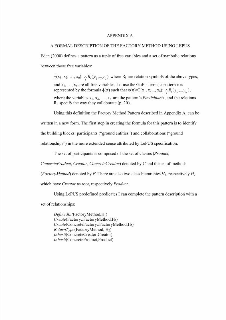
8/6/2019 Tanase Thesis
http://slidepdf.com/reader/full/tanase-thesis 82/85
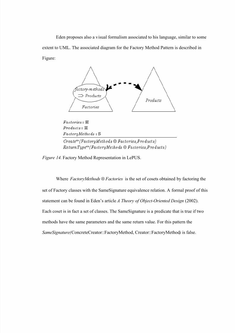
8/6/2019 Tanase Thesis
http://slidepdf.com/reader/full/tanase-thesis 83/85
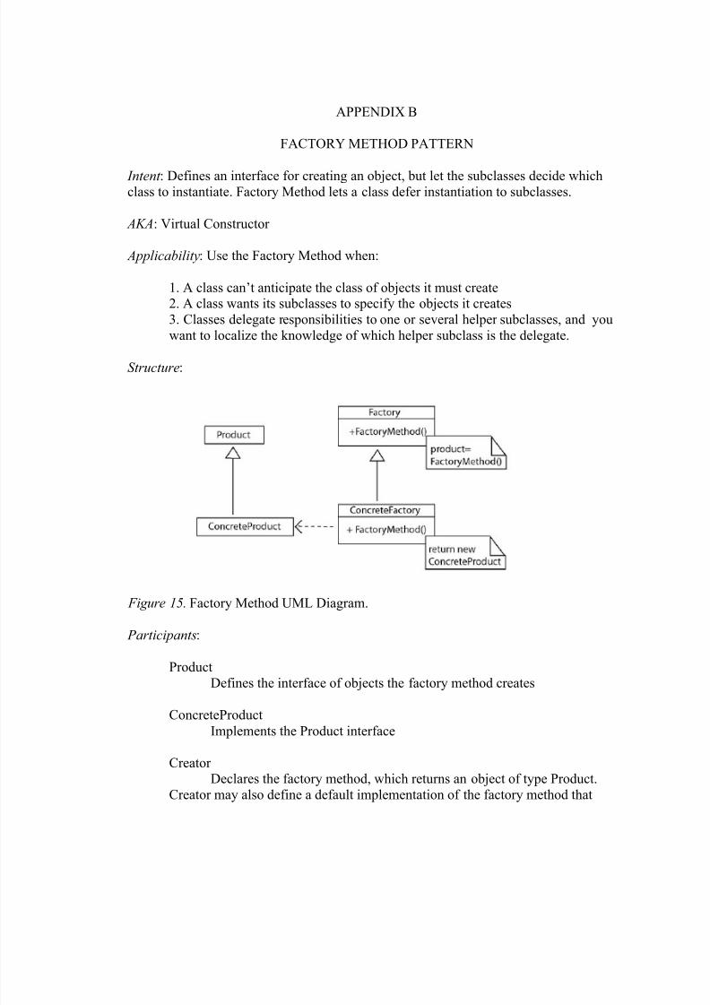
8/6/2019 Tanase Thesis
http://slidepdf.com/reader/full/tanase-thesis 84/85

8/6/2019 Tanase Thesis
http://slidepdf.com/reader/full/tanase-thesis 85/85
returns a default implementation of the factory method that return a default
ConcreteProduct object. It may call the factory method to create a Product object.
ConcreteCreator
Overrides the factory method to return an instance of a ConcreteProduct.
Collaborations:
Creator relies on its subclasses to define the factory method so that itreturns an instance of the appropriate ConcreteProduct (Gamma et. al., 1995, p.
107).