tag-it transponder protocol reference manual · tag-it™transponder protocol reference manual...
TRANSCRIPT
1
Tag-it™ Transponder Protocol
Reference Manual
SCBU032 (11-04-21-002) March 2000
Tag-it™Transponder Protocol Reference Manual March 2000
Edition Two - March 2000
This is the second edition of this manual.
Texas Instruments (TI) reserves the right to make changes to its products or services or to discontinue any product or service at any time without notice. TI provides customer assistance in various technical areas, but does not have full access to data concerning the use and applications of customer's products.
Therefore, TI assumes no liability and is not responsible for customer applications or product or software design or performance relating to systems or applications incorporating TI products. In addition, TI assumes no liability and is not responsible for infringement of patents and/or any other intellectual or industrial property rights of third parties, which may result from assistance provided by TI.
TI products are not designed, intended, authorized or warranted to be suitable for life support applications or any other life critical applications which could involve potential risk of death, personal injury or severe property or environmental damage.
The TIRIS logo and the words TIRIS and Tag-it are trademarks or registered trademarks of Texas Instruments Incorporated.
Copyright © 2000 Texas Instruments (TI)
This document may be downloaded onto a computer, stored and duplicated as necessary to support the use of the related TI products. Any other type of duplication, circulation or storage on data carriers in any manner not authorized by TI represents a violation of the applicable copyright laws and shall be prosecuted.
2
PREFACE
Read This First
About This Manual
This manual describes the RF data protocol used for communication between Tag-it compliant reader systems and TI Tag-it transponders which are based on the 37110 chip family (Product codes RI-I∗∗-110∗-∗∗ where ∗ may be any character).
The manual contains the following chapters:
Chapter 1: Introduction and Basics
Chapter 2: Transponder Protocol Structure
Chapter 3: List of Commands
Purpose
Designed for Texas Instruments TIRIS development partners, this document is the Transponder Protocol reference manual for the Tag-it™ Reader-to-Transponder communications software protocol. In addition, the Host Protocol Reference Manual for Host-to-Reader communications is available on request or through the Internet Documentation Center at http://www.tiris.com .
Audience
This reference manual is designed for use by TI partners, primarily engineers who have experience with TIRIS and radio frequency identification (RFID) components.
Numerical Representations
Unless otherwise noted, numbers are represented as decimal.
Hexadecimal numbers are represented with the suffix 16, e.g. A5F116
Binary numbers are represented with the suffix 2, e.g. 10112
In byte representations, the least significant bit (LSB) is bit 0 and the most significant bit (MSB) is bit 7.
3
Tag-it™Transponder Protocol Reference Manual March 2000
Explanation of Symbols and Warnings
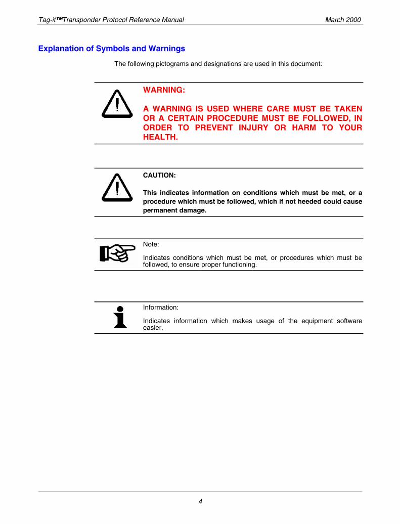
The following pictograms and designations are used in this document:
WARNING: A WARNING IS USED WHERE CARE MUST BE TAKEN OR A CERTAIN PROCEDURE MUST BE FOLLOWED, IN ORDER TO PREVENT INJURY OR HARM TO YOUR HEALTH.
CAUTION: This indicates information on conditions which must be met, or a procedure which must be followed, which if not heeded could cause permanent damage.
Note: Indicates conditions which must be met, or procedures which must be followed, to ensure proper functioning.
Information: Indicates information which makes usage of the equipment software easier.
4
Contents
Chapter 1: Introduction .............................................................................................................9
1.1 System Components .....................................................................................................10 1.1.1 Tag-it Reader ..........................................................................................................10 1.1.2 Transponder............................................................................................................10 1.1.3 System Overview....................................................................................................11
1.2 Transponder Protocol Overview ..................................................................................11 1.2.1 Description ..............................................................................................................11 1.2.2 Principle of Operation .............................................................................................12 1.2.3 Addressed Operations ............................................................................................12 1.2.4 Non-Addressed Operations ....................................................................................13 1.2.5 Transponder Version ..............................................................................................13
1.3 Reader-to-Transponder Communication.....................................................................14 1.3.1 Method ....................................................................................................................14 1.3.2 Framing...................................................................................................................16
1.4 Transponder to Reader Communication .....................................................................18 1.4.1 Parameters .............................................................................................................18 1.4.2 Method ....................................................................................................................19 1.4.3 Framing...................................................................................................................21
1.5 Simultaneous Identification (SID) ................................................................................22
1.6 EEPROM Programming Burst.......................................................................................23
1.7 Receiver Recovery Time ...............................................................................................24
1.8 Memory Organization ....................................................................................................25
1.9 Block Locking.................................................................................................................26 1.9.1 User Block Locking .................................................................................................26 1.9.2 Factory Block Locking.............................................................................................26
Chapter 2: Transponder Protocol Structure..........................................................................27
2.1 Command Structure ......................................................................................................28
2.2 Frames Overview ...........................................................................................................28
5
Tag-it™Transponder Protocol Reference Manual March 2000
Chapter 3: List of Commands.................................................................................................31
3.1 Command Code Reference Tables ..............................................................................32
3.2 Transponder Message Error Codes.............................................................................33
3.3 Commands......................................................................................................................34 3.3.1 Get_Block Request.................................................................................................34 3.3.2 Get_Block Response ..............................................................................................35 3.3.3 Get_Version Request .............................................................................................36 3.3.4 Get_Version Response...........................................................................................37 3.3.5 Put_Block Request .................................................................................................38 3.3.6 Put_Block Response ..............................................................................................39 3.3.7 Put_Block_Lock Request........................................................................................40 3.3.8 Put_Block_Lock Response.....................................................................................41 3.3.9 Lock_Block Request ...............................................................................................42 3.3.10 Lock_Block Response ..........................................................................................43 3.3.11 SID_Poll Request .................................................................................................44 3.3.12 SID_Poll Response...............................................................................................45 3.3.13 Quiet Request .......................................................................................................46 3.3.14 Quiet Response ....................................................................................................46
3.4 SID Mechanism...............................................................................................................47 3.4.1 SID_Poll Request: ..................................................................................................48 3.4.2 SID_Poll Request Parameters................................................................................49 3.4.3 SID_Poll Request processing by transponder........................................................49
3.5 Collision Detection ........................................................................................................50 3.5.1 Collision Management Algorithm............................................................................51
3.6 CRC .................................................................................................................................53
APPENDIX A: Memory Structure of Tag-it Inlays .................................................................54
APPENDIX B: Terms and Abbreviations................................................................................55
6
List of Figures
Figure 1: Typical Tag-it Transponder ................................................................................10
Figure 2: High Bit .................................................................................................................15
Figure 3: Low Bit ..................................................................................................................15
Figure 4: Start of Frame Synchronization Pattern (Reader-to-Transponder) ................16
Figure 5: End of Frame Synchronization Pattern (Reader-to-Transponder)..................17
Figure 6: Example of the Transmission of a Sequence of Data Bits ..........................17
Figure 7: Transponder-to-Reader Frequency Spectrum..................................................18
Figure 8: Data Encoding HIGH Bit (Transponder-to-Reader) ..........................................19
Figure 9: Data Encoding LOW Bit (Transponder-to-Reader)...........................................20
Figure 10: Data Encoding Example (Transponder-to-Reader) ........................................20
Figure 11: Start of Frame Synchronization Pattern (Transponder-to-Reader) ..............21
Figure 12: End of Frame Synchronization Pattern (Transponder-to-Reader) ...............21
Figure 13: Transaction Timing: Put Command.................................................................24
Figure 14: Transaction Timing: SID Poll Command.........................................................25
7
Tag-it™Transponder Protocol Reference Manual March 2000
List of Tables
Table 1: Downlink Parameters:...........................................................................................14
Table 2: Downlink Parameter Clock Cycles ......................................................................14
Table 3: Uplink Parameters (Transponder-to-Reader) .....................................................24
Table 4: Transponder Request Frame Structure ..............................................................28
Table 5: Transponder Response Frame Structure ...........................................................28
Table 6: Transponder Request Protocol Frame................................................................29
Table 7: Transponder Response Protocol Frame.............................................................30
Table 8: Transponder Protocol Command Codes............................................................32
Table 9: Lock Flags..............................................................................................................32
Table 10: Transponder Message Error Codes ..................................................................33
Table 11: Get_Block Request .............................................................................................34
Table 12: Get Block Response ...........................................................................................35
Table 13: Get_Version Request ..........................................................................................36
Table 14: Get_Version Response.......................................................................................37
Table 15: Put_Block Request..............................................................................................38
Table 16: Put_Block Response...........................................................................................39
Table 17: Put_Block_Lock Request ...................................................................................40
Table 18: Put_Block_Lock Response ................................................................................41
Table 19: Lock_Block Request ...........................................................................................42
Table 20: Lock_Block Response........................................................................................43
Table 21: SID_Poll Request.................................................................................................44
Table 22: SID_Poll Response..............................................................................................45
Table 23: Quiet Request ......................................................................................................46
Table 24: CRC Definition .....................................................................................................53
8
CHAPTER 1
Introduction
Topic Page
1.1 System Components .....................................................................................................10 1.1.1 Tag-it Reader ..........................................................................................................10 1.1.2 Transponder............................................................................................................10 1.1.3 System Overview....................................................................................................11
1.2 Transponder Protocol Overview ..................................................................................11 1.2.1 Description ..............................................................................................................11 1.2.2 Principle of Operation .............................................................................................12 1.2.3 Addressed Operations ............................................................................................12 1.2.4 Non-Addressed Operations ....................................................................................13 1.2.5 Transponder Version ..............................................................................................13
1.3 Reader to Transponder Communication .....................................................................14 1.3.1 Method ....................................................................................................................14 1.3.2 Framing...................................................................................................................16
1.4 Transponder to Reader Communication .....................................................................18 1.4.1 Parameters .............................................................................................................18 1.4.2 Method ....................................................................................................................19 1.4.3 Framing...................................................................................................................21
1.5 Simultaneous Identification (SID) ................................................................................22
1.6 EEPROM Programming Burst.......................................................................................23
1.7 Receiver Recovery Time ...............................................................................................24
1.8 Memory Organization ....................................................................................................25
1.9 Block Locking.................................................................................................................26 1.9.1 User Block Locking .................................................................................................26 1.9.2 Factory Block Locking.............................................................................................26
9
Tag-it™Transponder Protocol Reference Manual March 2000
1.1 System Components
The Tag-it TM system comprises a reader and associated transponders. The reader is controlled by a host system which may be a PC, a larger computer, or some other type of intelligent device, for example a ticket printer. This chapter describes the system environment, the system components and how the RF system works.
1.1.1 Tag-it Reader
A typical Tag-it reader consists of an electronic board and an antenna. The board can be either battery or mains powered and is connected to its host (Application Processor) through a serial connection or a local area network. It sends energy and commands to, and receives signals from, the transponder through the antenna (aerial).
1.1.2 Transponder
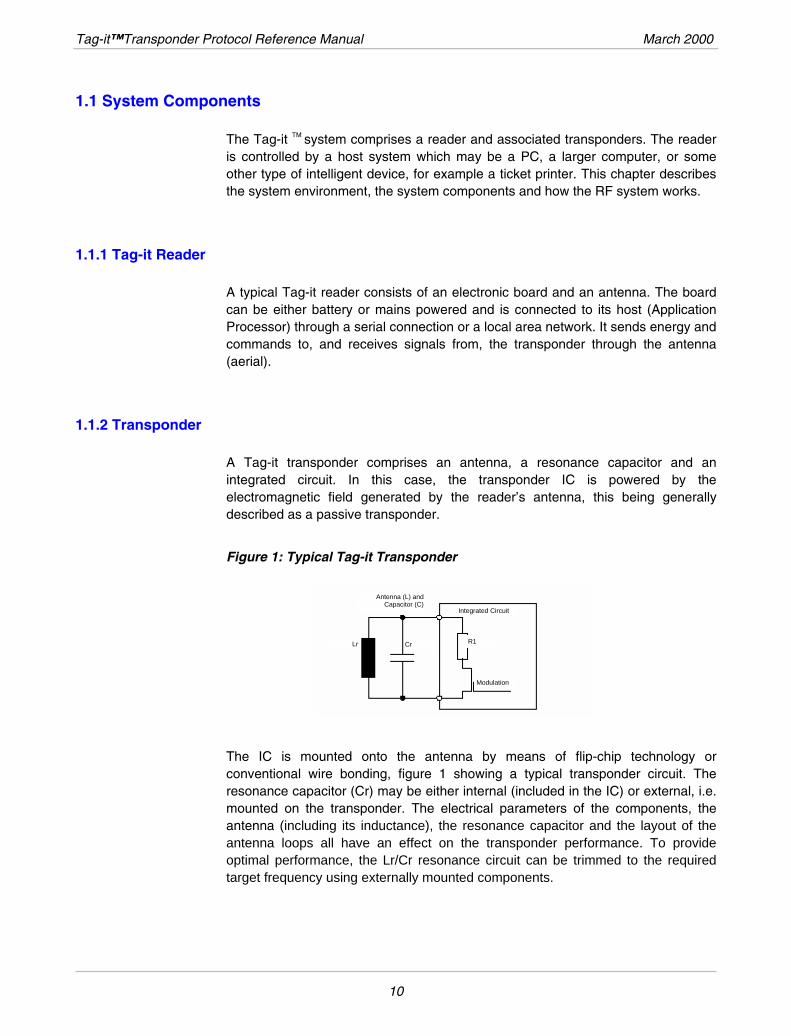
A Tag-it transponder comprises an antenna, a resonance capacitor and an integrated circuit. In this case, the transponder IC is powered by the electromagnetic field generated by the reader’s antenna, this being generally described as a passive transponder.
Figure 1: Typical Tag-it Transponder
Antenna (L) andCapacitor (C)
Lr Cr R1
Modulation
Integrated Circuit
The IC is mounted onto the antenna by means of flip-chip technology or conventional wire bonding, figure 1 showing a typical transponder circuit. The resonance capacitor (Cr) may be either internal (included in the IC) or external, i.e. mounted on the transponder. The electrical parameters of the components, the antenna (including its inductance), the resonance capacitor and the layout of the antenna loops all have an effect on the transponder performance. To provide optimal performance, the Lr/Cr resonance circuit can be trimmed to the required target frequency using externally mounted components.
10
March 2000 Introduction
1.1.3 System Overview
As previously stated, an RF System consists of the transponder, the reader and its antenna. The operating frequency is 13.56 MHz. This frequency is the center frequency of the 13.56 MHz ISM frequency band with a defined bandwidth of ±7 kHz, this being used to supply the tag with operating power and to maintain the data communication between transponder and reader.
During a transaction, the transponder is permanently powered by the signal sent by the reader. This signal also provides the clock frequency for the transponder. It is amplitude modulated to transmit requests from the reader to the transponder.
In order to transmit responses to the reader, the transponder derives the operating energy and the required clock from the reader’s power signal to generate its modulation frequencies.
The modulation depth is a system parameter and is a compromise between power management (storage capacitor on chip) and the target operating range of the (passive) transponders. It is influenced by the coupling factor between the reader’s antenna and the transponder, and thus by the distance between them.
1.2 Transponder Protocol Overview
Note: This is a generic document and does not relate to any specific Tag-it product. Some of the functions described here may not be implemented in all Tag-it products.
1.2.1 Description
The Tag-it transponder protocol is half-duplex, the fundamental operation being a transaction which consists of:
• a request sent by the reader to the transponder
• a response sent back by the transponder to the reader
Both the request and the response contain a Command Code which specifies the operation to be (or that was) performed by the transponder.
The transponder NEVER initiates a response without having been instructed to do so by the reader. The request must have been fully understood by the transponder before it can respond. The presence of the 13.56 MHz carrier frequency will power up the transponder but does not generate a spontaneous emission (response) of any kind by the transponder.
11
Tag-it™Transponder Protocol Reference Manual March 2000
This mechanism is particularly useful when transponders of different technologies which may happen to use the same 13.56 MHz frequency are present in the reader field. Tag-it transponders will not start any emission without having been instructed to do so, allowing other transponders to be interrogated according to their own mechanism.
If a similar principle is used by the other technologies present, Tag-it transponders can be handled without external interference.
1.2.2 Principle of Operation
Each Tag-it transponder has a unique address which is factory-programmed and 32 bits long, thus allowing an address range of more than 4 billion individual addresses. The possibility cannot be excluded that at some future time, a previously used address is assigned to a new transponder. Considering the expected lifetime of transponders however, and based on statistical calculations, the probability that 2 transponders with the same address are present simultaneously in the same reader location is well below 10-10.
If several transponders are expected to be present in the read area (this is application dependent), the first step is to inventory them. This is done by the Simultaneous Identification (SID) mechanism described in Section 3.4 which results in the reader storing in its memory the addresses of each transponder present within its range. At this point, the reader may pass them on to the application processor.
Once each transponder has been inventoried by its unique individual address, individual transactions can be performed in a manner similar to the use of a phone number or the addressing of a workstation on a LAN by its address.
A transaction is carried out with a single transponder, which is identified by its address. The transaction may read an area of its memory, write to another area or process a more advanced feature.
1.2.3 Addressed Operations
In addressed mode, at a given point in time, a reader dialogs with only one transponder.
12
March 2000 Introduction
1.2.4 Non-Addressed Operations
If an application is so organized that one and only one transponder can be present in the reader field, it is possible to use the non-addressed mode. In this case, any transponder receiving a non-addressed request will execute it and send a response.
It is key to a successful implementation of the non-addressed operation that only one transponder is within the reader’s range. Otherwise, the following may occur:
• If the reader is trying to perform a read function (obtaining information from the transponder), 2 or more answers will be sent by transponders. These answers will collide, resulting in an unintelligible message at the reader’s side.
• If the reader is performing a write function (writing information to a memory area of the transponder), all reachable transponders will perform this function, and for the reasons stated above, their multiple responses will collide, such that the reader will not receive a clear confirmation that the operation has been performed correctly. This can result in severe data corruption or make the transponder unusable if the Lock Command has been used.
1.2.5 Transponder Version
Tag-it products have been designed as a family of products based on a common technology. This therefore means that transponders equipped with different IC’s, each IC having different features, may be present at the same time in a reader’s field.
It is possible, for instance, to find transponders with 256 bits of memory organized in blocks of 32 bits and other transponders with 1024 bits of memory organized in blocks of 128 bits, and still others equipped with enhanced security features.
These different types of transponders could be used for the same application (the application has adopted the most up-to-date products, but is however still using products from a previous generation) or for different applications (each application has chosen the product with the most suitable features).
In order to know what the characteristics of each transponder IC are, and thus be able to correctly request execution of commands, each Tag-it IC is programmed during manufacturing with its version number, its manufacturer code and additional information about memory size and structure.
By requesting this information from the transponder using a command supported by all Tag-it IC’s, the reader can determine the supported features and act according to the IC capabilities.
13
Tag-it™Transponder Protocol Reference Manual March 2000
This guarantees that in a given application, upward compatibility with new products can be achieved, thus allowing each application to take advantage of any new features to improve the overall performance. Across applications, products with different features can co-exist and be handled by a common reader.
It is the responsibility of the reader and/or the application processor to know by reading the IC version number what the transponder’s detailed characteristics are. As more Tag-it chip families will become available, these characteristics will be described on the tag datasheet(s).
1.3 Reader-to-Transponder Communication
1.3.1 Method
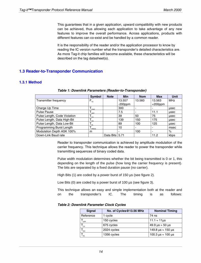
Table 1: Downlink Parameters (Reader-to-Transponder)
Symbol Note Min Nom Max Unit Transmitter frequency FTX 13.557 13.560 13.563 MHz
-200ppm +200ppm Charge Up Time TCHG 300 - - µsec Pulse Pause TOFF 7.5 - 11.1 µsec Pulse Length, Code Violation TCV 39 50 75 µsec Pulse Length, Data High-Bit TDH 139 150 175 µsec Pulse Length, Data Low-Bit TDL 89 100 125 µsec Programming Burst Length TPROG 10 - - msec Modulation Depth ASK 100% m - 100 - % Down-Link Baud rate Data Bits 5.71 11.2 kbps
Reader to transponder communication is achieved by amplitude modulation of the carrier frequency. This technique allows the reader to power the transponder while transmitting sequences of binary coded data.
Pulse width modulation determines whether the bit being transmitted is 0 or 1, this depending on the length of the pulse (how long the carrier frequency is present). The bits are separated by a fixed duration pause (no carrier).
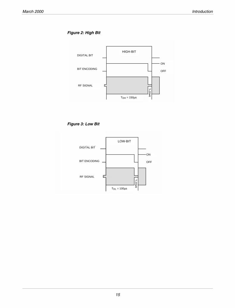
High Bits (1) are coded by a power burst of 150 µs (see figure 2).
Low Bits (0) are coded by a power burst of 100 µs (see figure 3).
This technique allows an easy and simple implementation both at the reader and on the transponder’s IC. The timing is as follows:
Table 2: Downlink Parameter Clock Cycles
Signal No. of [email protected] MHz Nominal Timing
Reference 1 cycle 74 ns
TOFF 150 cycles 11.1 ≈ 11µs
TCV 675 cycles 49.9 µs ≈ 50 µs
TDH 2024 cycles 149.8 µs ≈ 150 µs
TDL 1356 cycles 100.3 µs ≈ 100 µs
14
March 2000 Introduction
Figure 2: High Bit
RF SIGNAL
TDH = 150µs
TP (11µs)
ON
OFF
DIGITAL BIT HIGH-BIT
BIT ENCODING
Figure 3: Low Bit
TDL = 100µs
TP (11µs)
LOW-BIT
RF SIGNAL
BIT ENCODING
DIGITAL BITDIGITAL BIT
BIT ENCODING
ON
OFF
15
Tag-it™Transponder Protocol Reference Manual March 2000
1.3.2 Framing
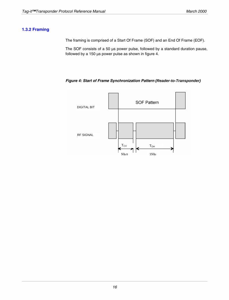
The framing is comprised of a Start Of Frame (SOF) and an End Of Frame (EOF).
The SOF consists of a 50 µs power pulse, followed by a standard duration pause, followed by a 150 µs power pulse as shown in figure 4.
Figure 4: Start of Frame Synchronization Pattern (Reader-to-Transponder)
TDH
RF SIGNAL
DIGITAL BIT
TCV
50μs 150μ
16
March 2000 Introduction
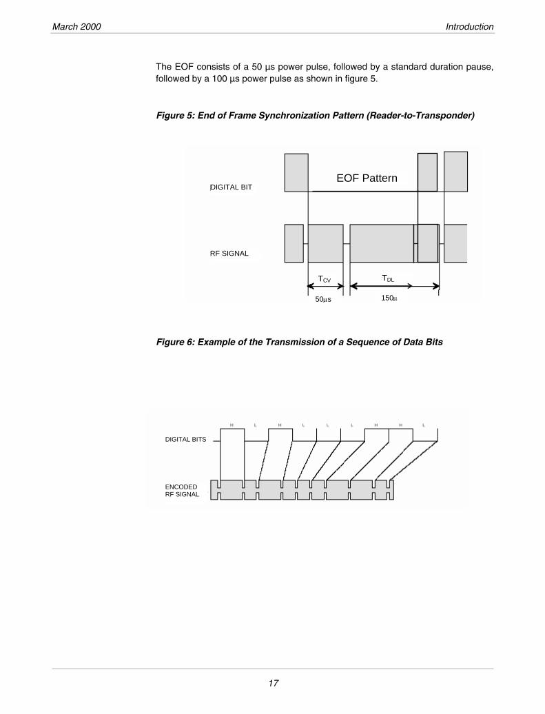
The EOF consists of a 50 µs power pulse, followed by a standard duration pause, followed by a 100 µs power pulse as shown in figure 5.
Figure 5: End of Frame Synchronization Pattern (Reader-to-Transponder)
TDL
RF SIGNAL
EOF Pattern
100µs
DIGITAL BIT
TCV
50μs 150μ
Figure 6: Example of the Transmission of a Sequence of Data Bits
DIGITAL BITS
ENCODED RF SIGNAL
17
Tag-it™Transponder Protocol Reference Manual March 2000
1.4 Transponder to Reader Communication
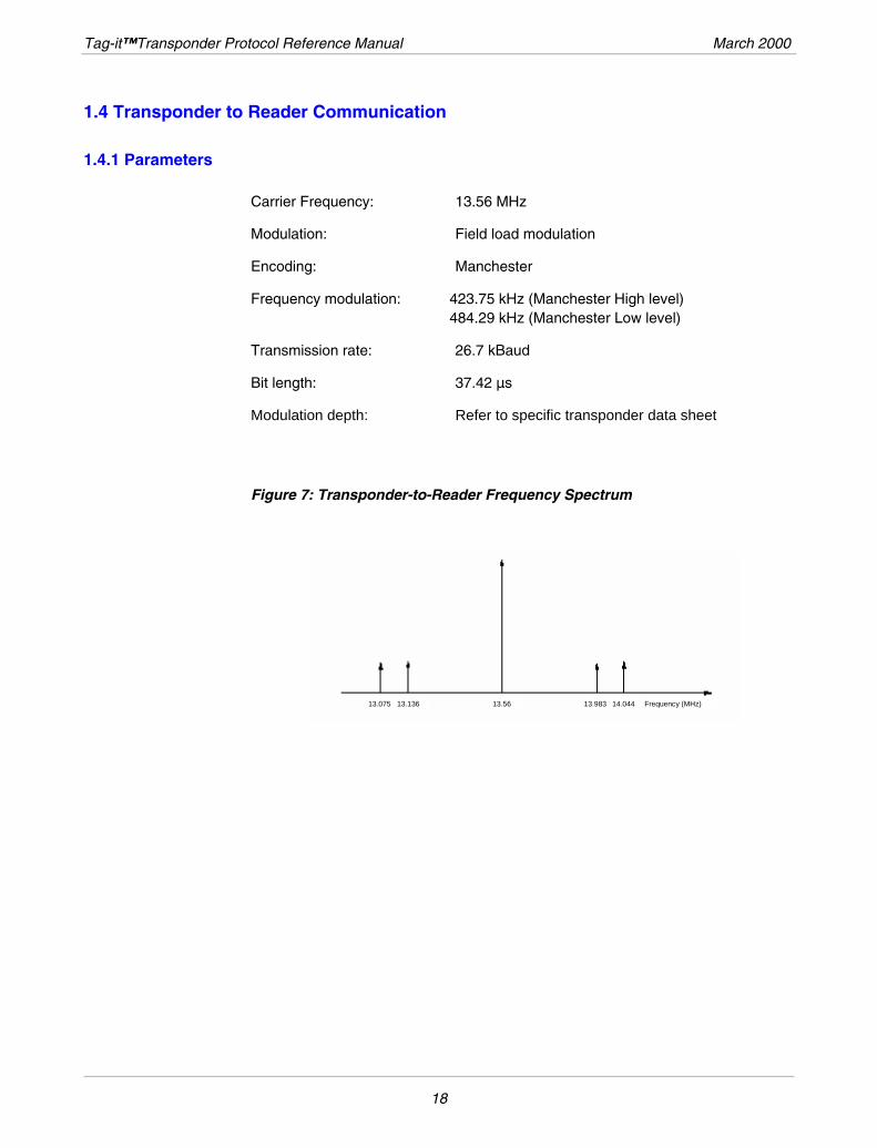
1.4.1 Parameters
Carrier Frequency: 13.56 MHz
Modulation: Field load modulation
Encoding: Manchester
Frequency modulation: 423.75 kHz (Manchester High level) 484.29 kHz (Manchester Low level)
Transmission rate: 26.7 kBaud
Bit length: 37.42 µs
Modulation depth: Refer to specific transponder data sheet
Figure 7: Transponder-to-Reader Frequency Spectrum
13.075 13.136 13.56 13.983 14.044 Frequency (MHz)
18
March 2000 Introduction
1.4.2 Method
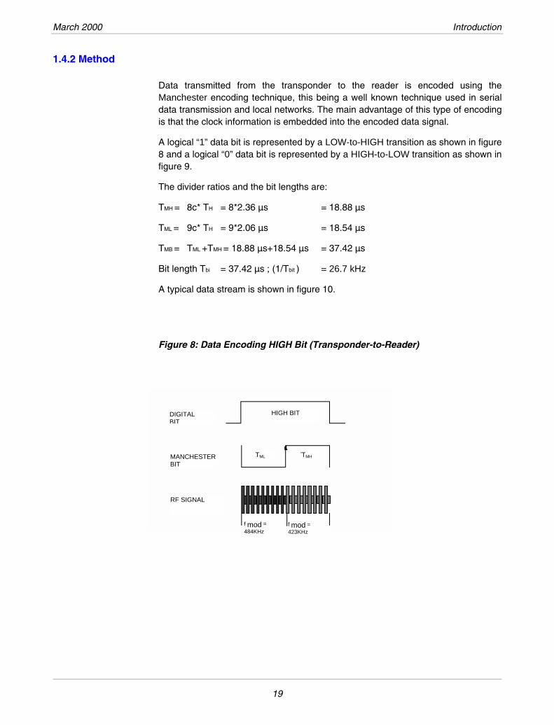
Data transmitted from the transponder to the reader is encoded using the Manchester encoding technique, this being a well known technique used in serial data transmission and local networks. The main advantage of this type of encoding is that the clock information is embedded into the encoded data signal.
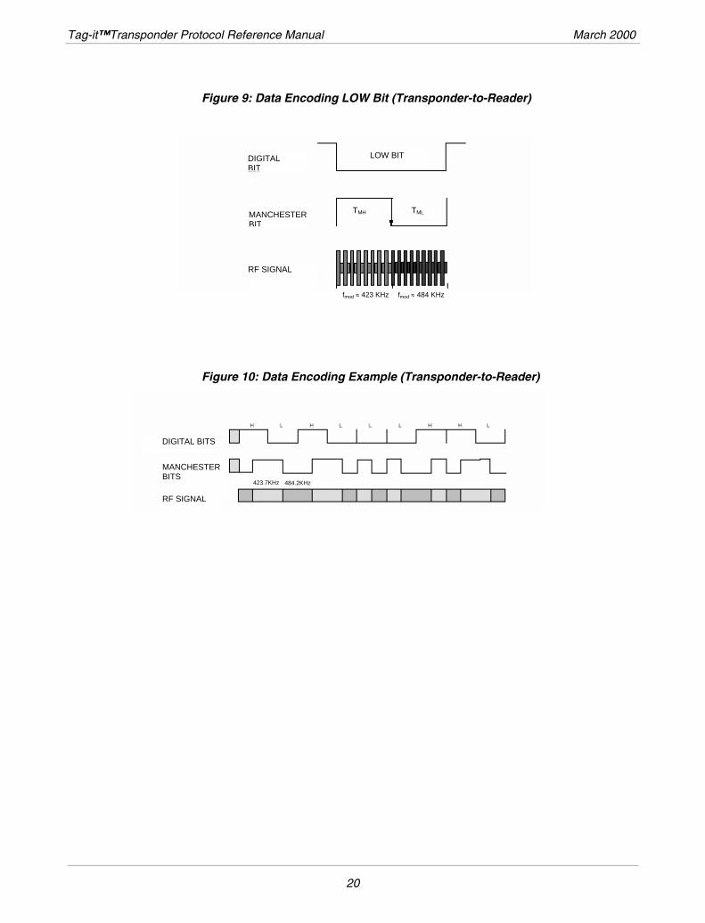
A logical “1” data bit is represented by a LOW-to-HIGH transition as shown in figure 8 and a logical “0” data bit is represented by a HIGH-to-LOW transition as shown in figure 9.
The divider ratios and the bit lengths are:
TMH = 8c* TH = 8*2.36 µs = 18.88 µs
TML = 9c* TH = 9*2.06 µs = 18.54 µs
TMB = TML +TMH = 18.88 µs+18.54 µs = 37.42 µs
Bit length Tbi = 37.42 µs ; (1/Tbit ) = 26.7 kHz
A typical data stream is shown in figure 10.
Figure 8: Data Encoding HIGH Bit (Transponder-to-Reader)
RF SIGNAL
DIGITAL BIT
MANCHESTER BIT
f mod = 484KHz
HIGH BIT
f mod = 423KHz
TML TMH
19
Tag-it™Transponder Protocol Reference Manual March 2000
Figure 9: Data Encoding LOW Bit (Transponder-to-Reader)
RF SIGNAL
fmod ≈ 423 KHz fmod ≈ 484 KHz
DIGITAL BIT
MANCHESTERBIT
LOW BIT
TMLTMH
Figure 10: Data Encoding Example (Transponder-to-Reader)
DIGITAL BITS
MANCHESTER BITS
RF SIGNAL
423.7KHz 484.2KHz
20
March 2000 Introduction
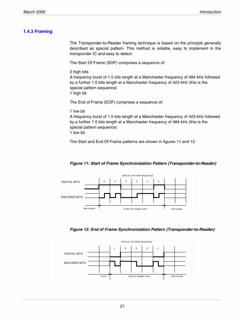
1.4.3 Framing
The Transponder-to-Reader framing technique is based on the principle generally described as special pattern. This method is reliable, easy to implement in the transponder IC and easy to detect.
The Start Of Frame (SOF) comprises a sequence of:
2 high bits A frequency burst of 1.5 bits length at a Manchester frequency of 484 kHz followed by a further 1.5 bits length at a Manchester frequency of 423 kHz (this is the special pattern sequence) 1 high bit
The End of Frame (EOF) comprises a sequence of:
1 low bit A frequency burst of 1.5 bits length at a Manchester frequency of 423 kHz followed by a further 1.5 bits length at a Manchester frequency of 484 kHz (this is the special pattern sequence) 1 low bit
The Start and End Of Frame patterns are shown in figures 11 and 12.
Figure 11: Start of Frame Synchronization Pattern (Transponder-to-Reader)
Figure 12: End of Frame Synchronization Pattern (Transponder-to-Reader)
SPECIAL PATTERN SEQUENCE
DIGITAL BITS
ENCODED BITS
PRE PHASE START OF FRAME SYNC DATA/CMD
DIGITAL BITS
ENCODED BITS
DATA END OF FRAME SYNC END PHASE
SPECIAL PATTERN SEQUENCE
21
Tag-it™Transponder Protocol Reference Manual March 2000
1.5 Simultaneous Identification (SID)
The SID mechanism offers the capability to inventory in a very short time a large number of transponders by their unique address, provided they are within the reader operating range.
The SID mechanism is based on an algorithm handled by the reader:
• Each transponder has a unique address.
• Transponders are interrogated by a sequence of SID Requests, using a special addressing scheme.
• If two or more transponders answer to the same interrogation, the collision is detected and stored into reader's memory.
• If only one transponder answers, its address is registered into the reader's memory. It will not be interrogated again during the current SID cycle.
• The reader then executes the collision handling algorithm, which results in the interrogation of transponders not yet identified by a modified addressing scheme.
• The cycle is continued until no collision is detected, i.e. all transponders have been identified and their address stored in the reader's memory. The inventory of transponders is then complete.
The collision-handling algorithm theoretically permits a 100% probability that all the transponders that are present in the reader’s range are be detected. However, in real applications, mutual influence of transponders may affect the result.
If only one transponder is present, a single SID Request is needed.
If 2 or more transponders are present, the average number of SID Requests per transponder stabilizes at around 0.40. While the number of SID Requests per transponder varies from one set of transponders to another, simulation has shown that the maximum never exceeds 0.75, and may even decrease when the number of transponders increases. The minimum may be as low as 0.10, although this is of lesser importance even if it improves the average performance.
The fact that the maximum never exceeds 0.75 whatever the number of transponders is means that all transponders are guaranteed to inventory within a time proportional to the number of transponders, irrespective of how many transponders there are.
The SID mechanism is deterministic and linear. It is reliable and reproducible, as opposed to, for instance, other mechanisms based on physical parameter random deviations.
It allows the inventory of any number of transponders within a time proportional to the number of transponders present. Only physical influences, i.e. the coupling of resonant circuits, can limit the performance in practice.
22
March 2000 Introduction
Some other advantages are:
The transponders have a unique factory programmed address.
Transponders do not need to be powered between two SID Requests. Even if the reader keeps powered on, transponders moving in various orientations within the reader’s antenna field may not receive enough power to keep temporary information in memory. Since this is not required however, the whole process being handled by the reader, the impact of such an occurrence is drastically decreased.
A Quiet Request may be used to ask specific transponders to ignore any subsequent SID Request. This may be useful if it is found that some collisions could not be detected because the signal strength of the closest transponders is so much higher than that of more distant transponders. In this case, once the closest transponders have been inventoried, they are asked to stay Quiet, and another SID sequence is performed, to which only transponders not yet inventoried (with a possibly weaker signal) will respond, but without the risk of having this weaker signal masked by a stronger signal from a closer transponder. Again, this is only a matter of method selection in the reader software and thus offers optimal flexibility in implementation.
The detailed mechanism is explained in section 3.4.
1.6 EEPROM Programming Burst
Current Tag-it ICs use an EEPROM memory technology. This requires that after all requests requiring some writing action in the transponder, for example a Put Block Request, the powering carrier is kept on for a given time (Tprog). The required value for this can be found in the IC datasheet, the order of magnitude being around 10 ms.
Following the programming burst, the carrier must be switched off for the defined Interbit Pause time, indicating the end of the programming cycle to the transponder, and initiating the response, which follows after the defined receiver recovery time.
23
Tag-it™Transponder Protocol Reference Manual March 2000
1.7 Receiver Recovery Time
Once the reader has sent a complete request, its electronic circuits need time to switch to the receiving mode.
In order to allow the reader to perform this switch, the transponder IC implements a time delay (TREC) before sending its response. If no answer has been received by the reader after this time, it indicates that the transponder has probably not received or correctly processed the request.
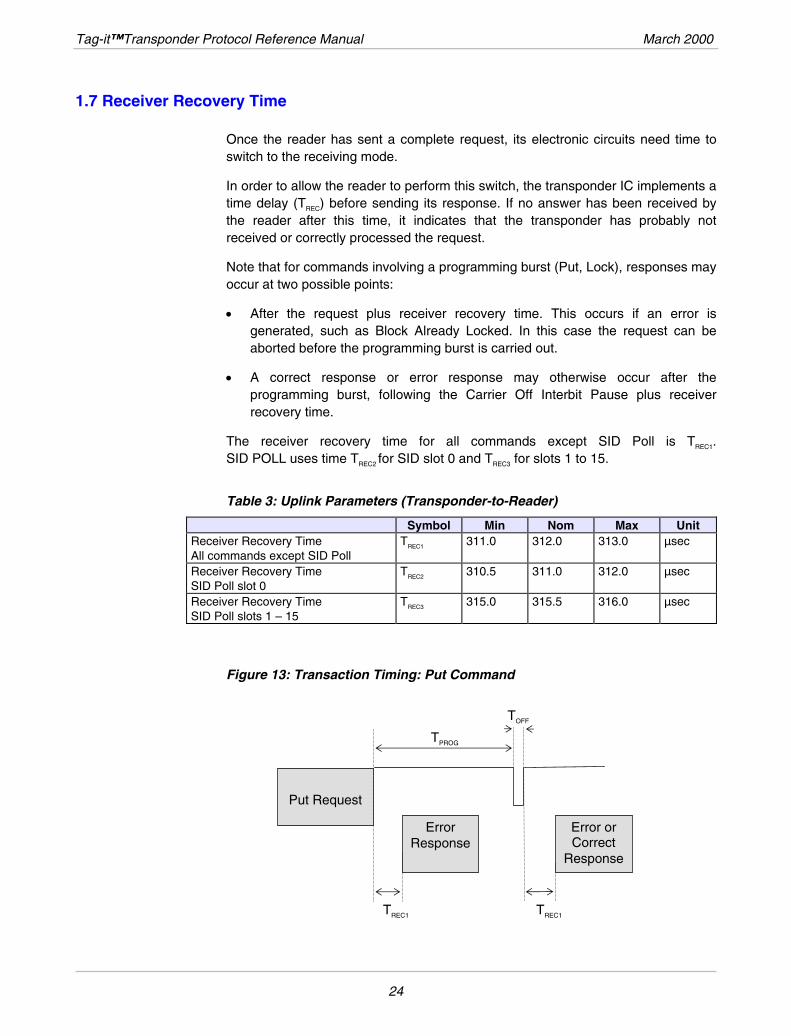
Note that for commands involving a programming burst (Put, Lock), responses may occur at two possible points:
• After the request plus receiver recovery time. This occurs if an error is generated, such as Block Already Locked. In this case the request can be aborted before the programming burst is carried out.
• A correct response or error response may otherwise occur after the programming burst, following the Carrier Off Interbit Pause plus receiver recovery time.
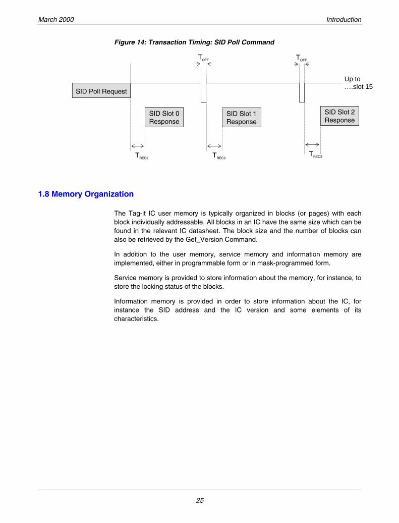
The receiver recovery time for all commands except SID Poll is TREC1. SID POLL uses time TREC2 for SID slot 0 and TREC3 for slots 1 to 15.
Table 3: Uplink Parameters (Transponder-to-Reader)
Symbol Min Nom Max Unit Receiver Recovery Time All commands except SID Poll
TREC1 311.0 312.0 313.0 µsec
Receiver Recovery Time SID Poll slot 0
TREC2 310.5 311.0 312.0 µsec
Receiver Recovery Time TREC3 315.0 315.5 316.0 µsec SID Poll slots 1 – 15
Figure 13: Transaction Timing: Put Command
TOFF
ErrorResponse
TREC1
TPROG
Error or Correct
Response
Put Request
TREC1
24
March 2000 Introduction
Figure 14: Transaction Timing: SID Poll Command
TOFFTOFF
1.8 Memory Organization
The Tag-it IC user memory is typically organized in blocks (or pages) with each block individually addressable. All blocks in an IC have the same size which can be found in the relevant IC datasheet. The block size and the number of blocks can also be retrieved by the Get_Version Command.
In addition to the user memory, service memory and information memory are implemented, either in programmable form or in mask-programmed form.
Service memory is provided to store information about the memory, for instance, to store the locking status of the blocks.
Information memory is provided in order to store information about the IC, for instance the SID address and the IC version and some elements of its characteristics.
SID Poll Request
SID Slot 0Response
TREC2 TREC3
Up to ….slot 15
TREC3
SID Slot 1Response
SID Slot 2Response
25
Tag-it™Transponder Protocol Reference Manual March 2000
1.9 Block Locking
A block can only be locked once. This can be done when the IC is manufactured (factory-locked), or by the user at any time (user-locked).
A locked block (regardless of which method was used to lock it) cannot be modified by any subsequent command. It is permanently locked and the data contained in that block cannot be changed.
Two bits of service memory are reserved for each block to store information about its lock status.
1.9.1 User Block Locking
Any block can be locked once by the user. This is especially useful if it is desired to permanently program information about the object or the person the transponder is related to. This could be, for example, a serial number, a manufacturing date, or a driving license number. Temporary information such as a flight number or the next destination, which may need to be modified, should not be locked.
1.9.2 Factory Block Locking
It is only possible to factory lock a block during the manufacturing process, it cannot be done later. This can be useful to guarantee that specific transponders are for use only by a specific customer or application.
It is possible, for instance, to factory lock the first block after the primary user code (for example: an airline code) has been programmed. This guarantees that all transponders with the specific user code in the first block and having the same first block factory locked have been manufactured and delivered to the airline.
Factory locking is subject to specific conditions, therefore please contact a Texas Instruments sales office in case of inquiries.
26
Transponder Protocol Structure
CHAPTER 2
Topic Page
2.1 Command Structure ......................................................................................................28
2.2 Frames Overview ...........................................................................................................28
27
Tag-it™Transponder Protocol Reference Manual March 2000
2.1 Command Structure
The reader issues a request to the transponder in the form of coded instructions and parameters. The transponder replies with a response block containing status information and data.
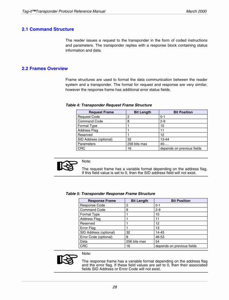
2.2 Frames Overview
Frame structures are used to format the data communication between the reader system and a transponder. The format for request and response are very similar, however the response frame has additional error status fields.
Table 4: Transponder Request Frame Structure
Request Frame Bit Length Bit Position Request Code 2 0-1 Command Code 8 2-9 Format Type 1 10 Address Flag 1 11 Reserved 1 12 SID Address (optional) 32 13-44 Parameters 256 bits max 45-… CRC 16 depends on previous fields
Note: The request frame has a variable format depending on the address flag. If this field value is set to 0, then the SID address field will not exist.
Table 5: Transponder Response Frame Structure
Response Frame Bit Length Bit Position Response Code 2 0-1 Command Code 8 2-9 Format Type 1 10 Address Flag 1 11 Reserved 1 12 Error Flag 1 13 SID Address (optional) 32 14-45 Error Code (optional) 8 46-53 Data 256 bits max 54 CRC 16 depends on previous fields
Note: The response frame has a variable format depending on the address flag and the error flag. If these field values are set to 0, then their associated fields SID Address or Error Code will not exist.
28
March 2000 Transponder Protocol Structure
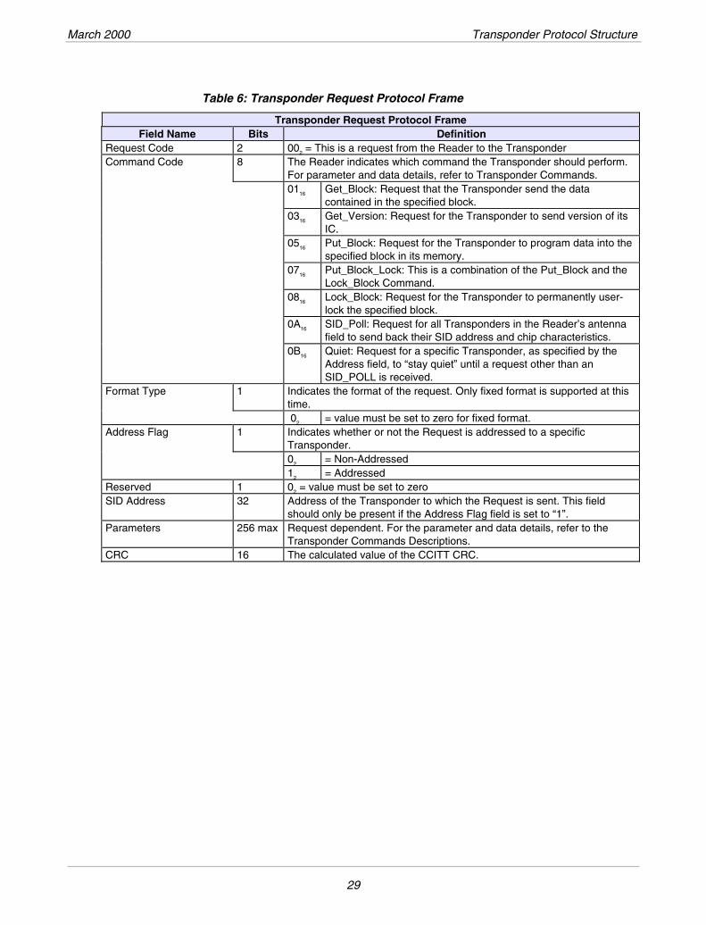
Table 6: Transponder Request Protocol Frame
Transponder Request Protocol Frame Bits Definition Field Name
Request Code 2 002 = This is a request from the Reader to the Transponder Command Code 8 The Reader indicates which command the Transponder should perform.
For parameter and data details, refer to Transponder Commands. 0116 Get_Block: Request that the Transponder send the data
contained in the specified block. 0316 Get_Version: Request for the Transponder to send version of its
IC. 0516 Put_Block: Request for the Transponder to program data into the
specified block in its memory. 0716 Put_Block_Lock: This is a combination of the Put_Block and the
Lock_Block Command. 0816 Lock_Block: Request for the Transponder to permanently user-
lock the specified block. 0A16 SID_Poll: Request for all Transponders in the Reader’s antenna
field to send back their SID address and chip characteristics. 0B16 Quiet: Request for a specific Transponder, as specified by the
Address field, to “stay quiet” until a request other than an SID_POLL is received.
Format Type 1 Indicates the format of the request. Only fixed format is supported at this time.
02 = value must be set to zero for fixed format. Address Flag 1 Indicates whether or not the Request is addressed to a specific
Transponder. 02 = Non-Addressed 12 = Addressed Reserved 1 02 = value must be set to zero SID Address 32 Address of the Transponder to which the Request is sent. This field
should only be present if the Address Flag field is set to “1”. Parameters 256 max Request dependent. For the parameter and data details, refer to the
Transponder Commands Descriptions. CRC 16 The calculated value of the CCITT CRC.
29
Tag-it™Transponder Protocol Reference Manual March 2000
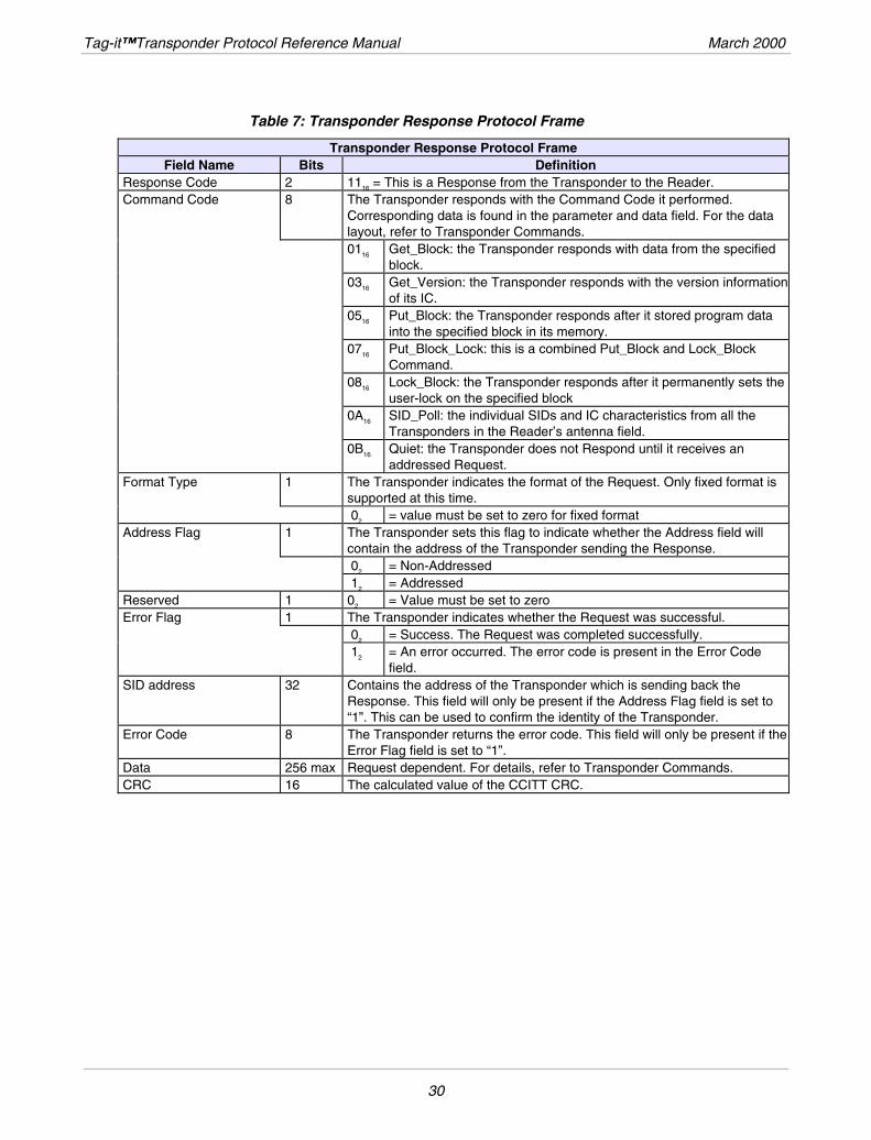
Table 7: Transponder Response Protocol Frame
Transponder Response Protocol Frame Field Name Bits Definition
Response Code 2 1116 = This is a Response from the Transponder to the Reader. Command Code 8 The Transponder responds with the Command Code it performed.
Corresponding data is found in the parameter and data field. For the data layout, refer to Transponder Commands.
0116 Get_Block: the Transponder responds with data from the specified block.
0316 Get_Version: the Transponder responds with the version information of its IC.
0516 Put_Block: the Transponder responds after it stored program data into the specified block in its memory.
0716 Put_Block_Lock: this is a combined Put_Block and Lock_Block Command.
0816 Lock_Block: the Transponder responds after it permanently sets the user-lock on the specified block
0A16 SID_Poll: the individual SIDs and IC characteristics from all the Transponders in the Reader’s antenna field.
0B16 Quiet: the Transponder does not Respond until it receives an addressed Request.
Format Type 1 The Transponder indicates the format of the Request. Only fixed format is supported at this time.
02 = value must be set to zero for fixed format Address Flag 1 The Transponder sets this flag to indicate whether the Address field will
contain the address of the Transponder sending the Response. 02 = Non-Addressed 12 = Addressed Reserved 1 02 = Value must be set to zero Error Flag 1 The Transponder indicates whether the Request was successful. 02 = Success. The Request was completed successfully. 12 = An error occurred. The error code is present in the Error Code
field. SID address 32 Contains the address of the Transponder which is sending back the
Response. This field will only be present if the Address Flag field is set to “1”. This can be used to confirm the identity of the Transponder.
Error Code 8 The Transponder returns the error code. This field will only be present if the Error Flag field is set to “1”.
Data 256 max Request dependent. For details, refer to Transponder Commands. CRC 16 The calculated value of the CCITT CRC.
30
CHAPTER 3
List of Commands
Topic Page
3.1 Command Code Reference Tables ..............................................................................32
3.2 Transponder Message Error Codes.............................................................................33
3.3 Commands......................................................................................................................34 3.3.1 Get_Block Request.................................................................................................34 3.3.2 Get_Block Response ..............................................................................................35 3.3.3 Get_Version Request .............................................................................................36 3.3.4 Get_Version Response...........................................................................................37 3.3.5 Put_Block Request .................................................................................................38 3.3.6 Put_Block Response ..............................................................................................39 3.3.7 Put_Block_Lock Request........................................................................................40 3.3.8 Put_Block_Lock Response.....................................................................................41 3.3.9 Lock_Block Request ...............................................................................................42 3.3.10 Lock_Block Response ..........................................................................................43 3.3.11 SID_Poll Request .................................................................................................44 3.3.12 SID_Poll Response...............................................................................................45 3.3.13 Quiet Request .......................................................................................................46 3.3.14 Quiet Response ....................................................................................................46
3.4 SID Mechanism...............................................................................................................47 3.4.1 SID_Poll Request: ..................................................................................................48 3.4.2 SID_Poll Request Parameters................................................................................49 3.4.3 SID_Poll Request processing by transponder........................................................49
3.5 Collision Detection ........................................................................................................50 3.5.1 Collision Management Algorithm............................................................................51
3.6 CRC .................................................................................................................................53
31
Tag-it™Transponder Protocol Reference Manual March 2000
3.1 Command Code Reference Tables
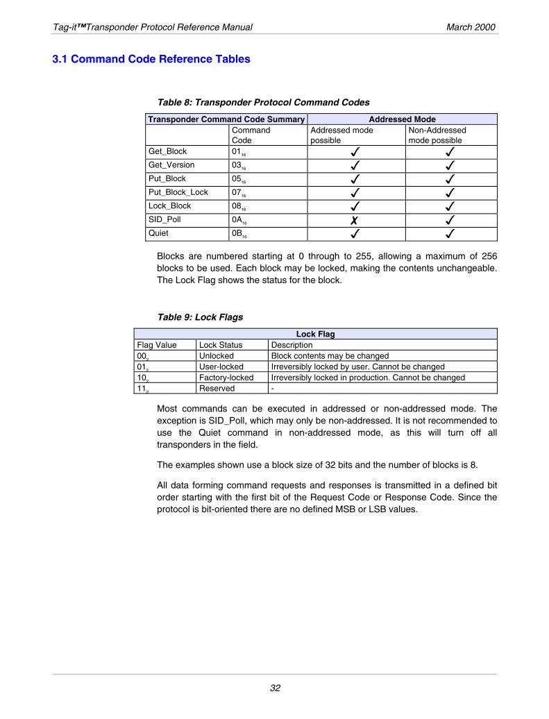
Table 8: Transponder Protocol Command Codes
Transponder Command Code Summary Addressed Mode Command
Code Addressed mode possible
Non-Addressed mode possible
Get_Block 0116 Get_Version 0316 Put_Block 0516 Put_Block_Lock 0716 Lock_Block 0816 SID_Poll 0A16 Quiet 0BB16
Blocks are numbered starting at 0 through to 255, allowing a maximum of 256 blocks to be used. Each block may be locked, making the contents unchangeable. The Lock Flag shows the status for the block.
Table 9: Lock Flags
Lock Flag Flag Value Lock Status Description 002 Unlocked Block contents may be changed 012 User-locked Irreversibly locked by user. Cannot be changed 102 Factory-locked Irreversibly locked in production. Cannot be changed 112 Reserved -
Most commands can be executed in addressed or non-addressed mode. The exception is SID_Poll, which may only be non-addressed. It is not recommended to use the Quiet command in non-addressed mode, as this will turn off all transponders in the field.
The examples shown use a block size of 32 bits and the number of blocks is 8.
All data forming command requests and responses is transmitted in a defined bit order starting with the first bit of the Request Code or Response Code. Since the protocol is bit-oriented there are no defined MSB or LSB values.
32
March 2000 List of Commands
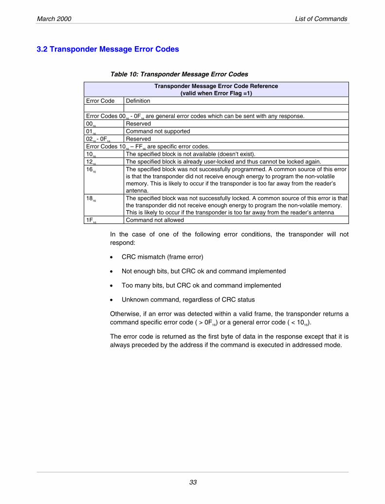
3.2 Transponder Message Error Codes
Table 10: Transponder Message Error Codes
Transponder Message Error Code Reference (valid when Error Flag =1)
Error Code Definition Error Codes 0016 - 0F16 are general error codes which can be sent with any response. 0016 Reserved 0116 Command not supported 0216 - 0F16 Reserved Error Codes 1016 – FF16 are specific error codes. 1016 The specified block is not available (doesn’t exist). 1216 The specified block is already user-locked and thus cannot be locked again. 1616 The specified block was not successfully programmed. A common source of this error
is that the transponder did not receive enough energy to program the non-volatile memory. This is likely to occur if the transponder is too far away from the reader’s antenna.
1816 The specified block was not successfully locked. A common source of this error is that the transponder did not receive enough energy to program the non-volatile memory. This is likely to occur if the transponder is too far away from the reader’s antenna
1F16 Command not allowed
In the case of one of the following error conditions, the transponder will not respond:
• CRC mismatch (frame error)
• Not enough bits, but CRC ok and command implemented
• Too many bits, but CRC ok and command implemented
• Unknown command, regardless of CRC status
Otherwise, if an error was detected within a valid frame, the transponder returns a command specific error code ( > 0F16) or a general error code ( < 1016).
The error code is returned as the first byte of data in the response except that it is always preceded by the address if the command is executed in addressed mode.
33
Tag-it™Transponder Protocol Reference Manual March 2000
3.3 Commands
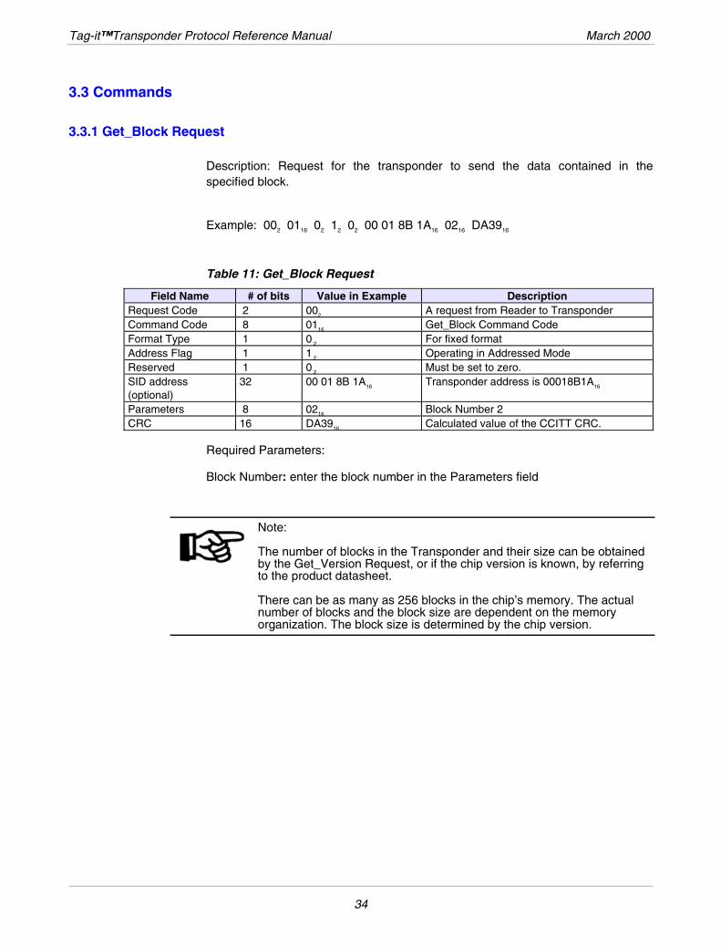
3.3.1 Get_Block Request
Description: Request for the transponder to send the data contained in the specified block.
Example: 002 0116 02 12 02 00 01 8B 1A16 0216 DA3916
Table 11: Get_Block Request
# of bits Value in Example Description Field Name Request Code 2 002 A request from Reader to Transponder Command Code 8 0116 Get_Block Command Code Format Type 1 0 2 For fixed format Address Flag 1 1 2 Operating in Addressed Mode Reserved 1 0 2 Must be set to zero. SID address (optional)
32 00 01 8B 1A16 Transponder address is 00018B1A16
Parameters 8 0216 Block Number 2 CRC 16 DA3916 Calculated value of the CCITT CRC.
Required Parameters:
Block Number: enter the block number in the Parameters field
Note: The number of blocks in the Transponder and their size can be obtained by the Get_Version Request, or if the chip version is known, by referring to the product datasheet. There can be as many as 256 blocks in the chip’s memory. The actual number of blocks and the block size are dependent on the memory organization. The block size is determined by the chip version.
34
March 2000 List of Commands
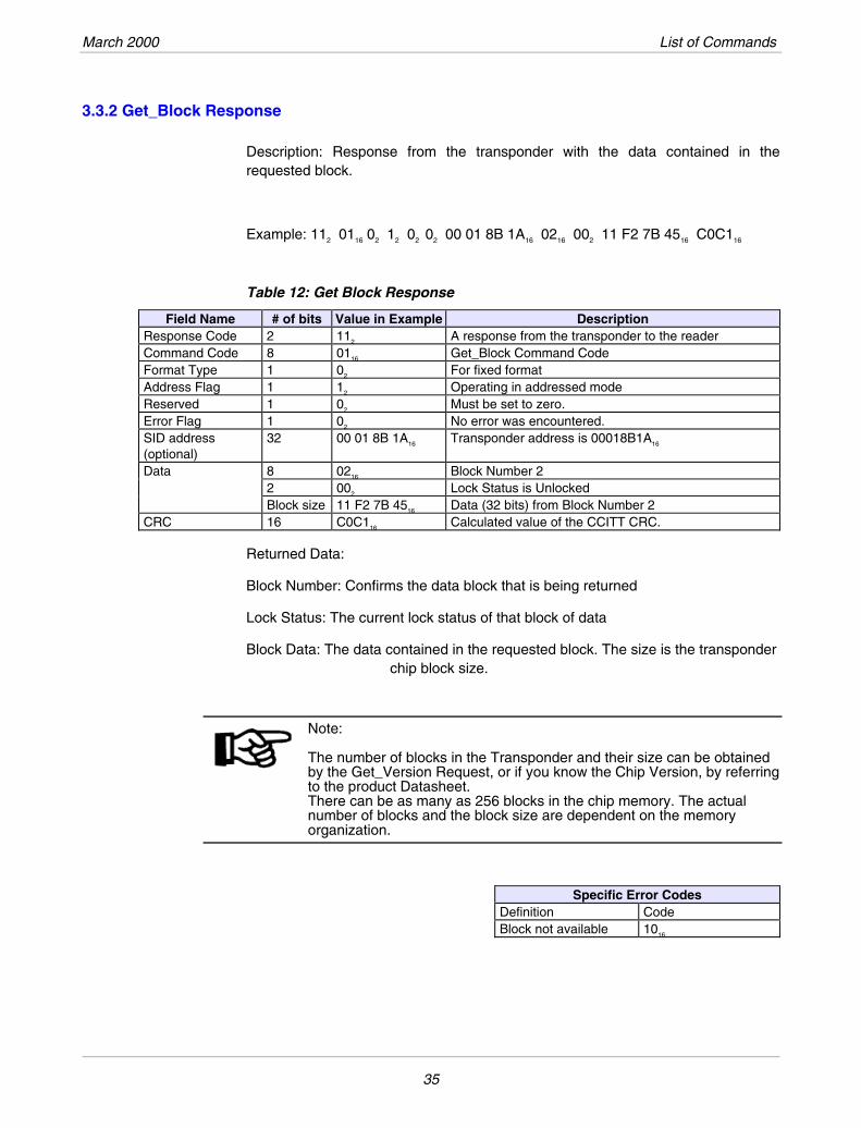
3.3.2 Get_Block Response
Description: Response from the transponder with the data contained in the requested block.
Example: 112 0116 02 12 02 02 00 01 8B 1A16 0216 002 11 F2 7B 4516 C0C116
Table 12: Get Block Response
Field Name # of bits Value in Example Description Response Code 2 112 A response from the transponder to the reader Command Code 8 0116 Get_Block Command Code Format Type 1 02 For fixed format Address Flag 1 12 Operating in addressed mode Reserved 1 02 Must be set to zero. Error Flag 1 02 No error was encountered. SID address (optional)
32 00 01 8B 1A16 Transponder address is 00018B1A16
Data 8 0216 Block Number 2 2 002 Lock Status is Unlocked Block size 11 F2 7B 4516 Data (32 bits) from Block Number 2 CRC 16 C0C116 Calculated value of the CCITT CRC.
Returned Data:
Block Number: Confirms the data block that is being returned
Lock Status: The current lock status of that block of data
Block Data: The data contained in the requested block. The size is the transponder chip block size.
Note: The number of blocks in the Transponder and their size can be obtained by the Get_Version Request, or if you know the Chip Version, by referring to the product Datasheet. There can be as many as 256 blocks in the chip memory. The actual number of blocks and the block size are dependent on the memory organization.
Specific Error Codes Definition Code Block not available 1016
35
Tag-it™Transponder Protocol Reference Manual March 2000
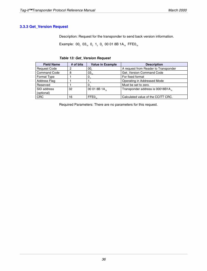
3.3.3 Get_Version Request
Description: Request for the transponder to send back version information.
Example: 002 0316 02 12 02 00 01 8B 1A16 FFE016
Table 13: Get_Version Request
Field Name # of bits Value in Example Description Request Code 2 002 A request from Reader to Transponder Command Code 8 0316 Get_Version Command Code Format Type 1 0 2 For fixed format Address Flag 1 1 2 Operating in Addressed Mode Reserved 1 0 2 Must be set to zero. SID address (optional)
32 00 01 8B 1A16 Transponder address is 00018B1A16
CRC 16 FFE016 Calculated value of the CCITT CRC.
Required Parameters: There are no parameters for this request.
36
March 2000 List of Commands
3.3.4 Get_Version Response
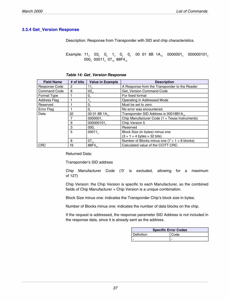
Description: Response from Transponder with SID and chip characteristics.
Example: 112 032 02 12 02 02 00 01 8B 1A16 00000012 0000001012 0002 000112 0716 88F416
Table 14: Get_Version Response
Field Name # of bits Value in Example Description Response Code 2 112 A Response from the Transponder to the Reader Command Code 8 0316 Get_Version Command Code Format Type 1 02 For fixed format Address Flag 1 12 Operating in Addressed Mode Reserved 1 02 Must be set to zero. Error Flag 1 02 No error was encountered. Data 32 00 01 8B 1A16 Transponder SID Address is 00018B1A16
7 00000012 Chip Manufacturer Code (1 = Texas Instruments) 9 0000001012 Chip Version 5 3 0002 Reserved 5 000112 Block Size (in bytes) minus one
(3 + 1 = 4 bytes = 32 bits) 8 0716 Number of Blocks minus one (7 + 1 = 8 blocks) CRC 16 88F416 Calculated value of the CCITT CRC.
Returned Data:
Transponder’s SID address
Chip Manufacturer Code (‘0’ is excluded, allowing for a maximum of 127)
Chip Version: the Chip Version is specific to each Manufacturer, so the combined fields of Chip Manufacturer + Chip Version is a unique combination.
Block Size minus one: indicates the Transponder Chip’s block size in bytes.
Number of Blocks minus one: indicates the number of data blocks on the chip.
If the request is addressed, the response parameter SID Address is not included in the response data, since it is already sent as the address.
Specific Error Codes
Definition Code - -
37
Tag-it™Transponder Protocol Reference Manual March 2000
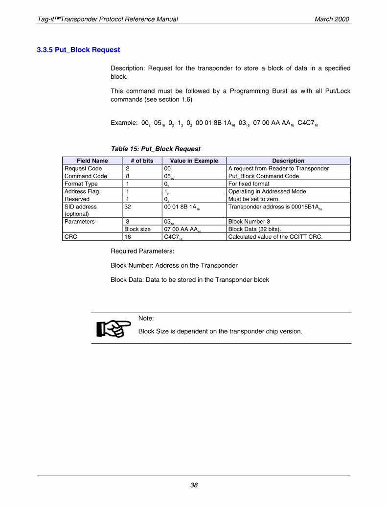
3.3.5 Put_Block Request
Description: Request for the transponder to store a block of data in a specified block.
This command must be followed by a Programming Burst as with all Put/Lock commands (see section 1.6)
Example: 002 0516 02 12 02 00 01 8B 1A16 0316 07 00 AA AA16 C4C716
Table 15: Put_Block Request
Field Name # of bits Value in Example Description Request Code 2 002 A request from Reader to Transponder Command Code 8 0516 Put_Block Command Code Format Type 1 02 For fixed format Address Flag 1 12 Operating in Addressed Mode Reserved 1 02 Must be set to zero. SID address (optional)
32 00 01 8B 1A16 Transponder address is 00018B1A16
Parameters 8 0316 Block Number 3 Block size 07 00 AA AA16 Block Data (32 bits). CRC 16 C4C716 Calculated value of the CCITT CRC.
Required Parameters:
Block Number: Address on the Transponder
Block Data: Data to be stored in the Transponder block
Note: Block Size is dependent on the transponder chip version.
38
March 2000 List of Commands
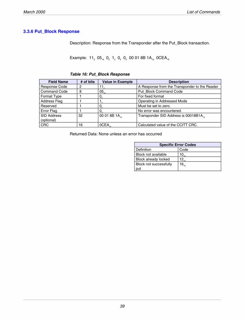
3.3.6 Put_Block Response
Description: Response from the Transponder after the Put_Block transaction.
Example: 112 0516 02 12 02 02 00 01 8B 1A16 0CEA16
Table 16: Put_Block Response
Field Name # of bits Value in Example Description Response Code 2 112 A Response from the Transponder to the Reader Command Code 8 0516 Put_Block Command Code Format Type 1 02 For fixed format Address Flag 1 12 Operating in Addressed Mode Reserved 1 02 Must be set to zero. Error Flag 1 02 No error was encountered. SID Address (optional)
32 00 01 8B 1A16 Transponder SID Address is 00018B1A16
CRC 16 0CEA16 Calculated value of the CCITT CRC.
Returned Data: None unless an error has occurred
Specific Error Codes Definition Code Block not available 1016
Block already locked 1216
Block not successfully put
1616
39
Tag-it™Transponder Protocol Reference Manual March 2000
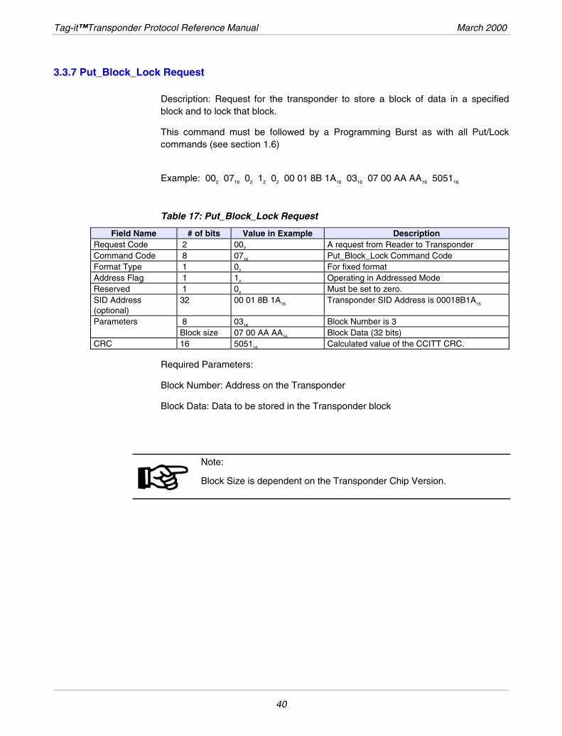
3.3.7 Put_Block_Lock Request
Description: Request for the transponder to store a block of data in a specified block and to lock that block.
This command must be followed by a Programming Burst as with all Put/Lock commands (see section 1.6)
Example: 002 0716 02 12 02 00 01 8B 1A16 0316 07 00 AA AA16 505116
Table 17: Put_Block_Lock Request
Field Name # of bits Value in Example Description Request Code 2 002 A request from Reader to Transponder Command Code 8 0716 Put_Block_Lock Command Code Format Type 1 02 For fixed format Address Flag 1 12 Operating in Addressed Mode Reserved 1 02 Must be set to zero. SID Address (optional)
32 00 01 8B 1A16 Transponder SID Address is 00018B1A16
Parameters 8 0316 Block Number is 3 Block size 07 00 AA AA16 Block Data (32 bits) CRC 16 505116 Calculated value of the CCITT CRC.
Required Parameters:
Block Number: Address on the Transponder
Block Data: Data to be stored in the Transponder block
Note: Block Size is dependent on the Transponder Chip Version.
40
March 2000 List of Commands
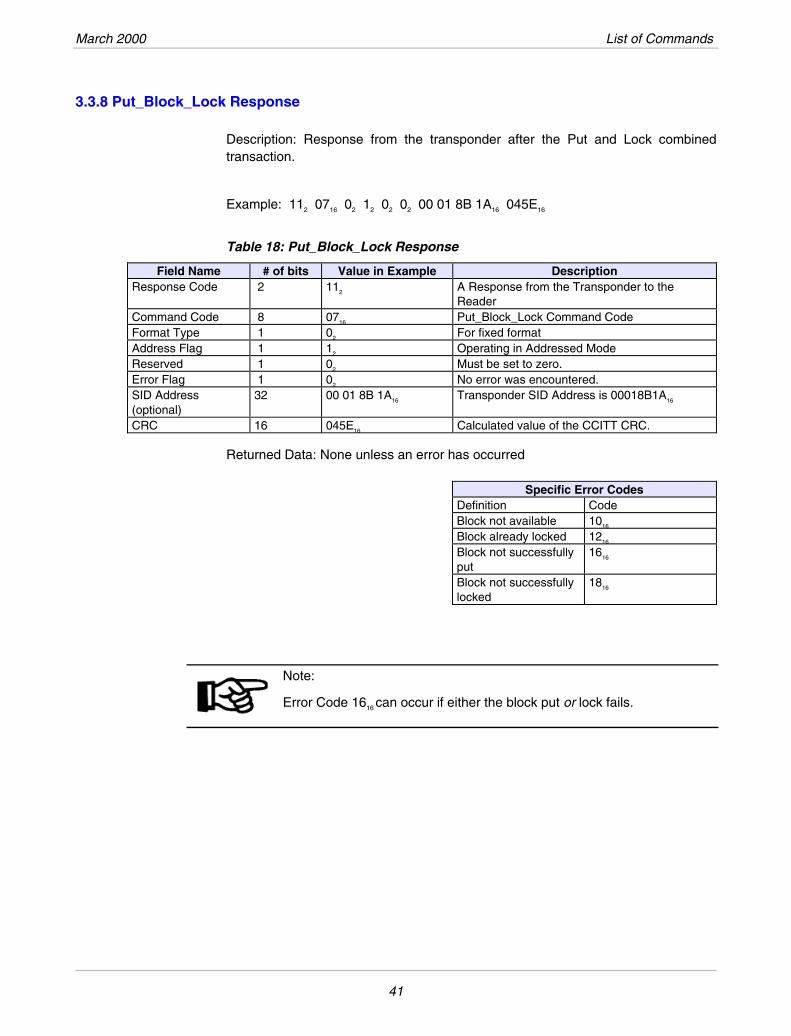
3.3.8 Put_Block_Lock Response
Description: Response from the transponder after the Put and Lock combined transaction.
Example: 112 0716 02 12 02 02 00 01 8B 1A16 045E16
Table 18: Put_Block_Lock Response
# of bits Value in Example Field Name Description Response Code 2 112 A Response from the Transponder to the
Reader Command Code 8 0716 Put_Block_Lock Command Code Format Type 1 02 For fixed format Address Flag 1 12 Operating in Addressed Mode Reserved 1 02 Must be set to zero. Error Flag 1 02 No error was encountered. SID Address (optional)
32 00 01 8B 1A16 Transponder SID Address is 00018B1A16
CRC 16 045E16 Calculated value of the CCITT CRC.
Returned Data: None unless an error has occurred
Specific Error Codes Definition Code Block not available 1016
Block already locked 1216
Block not successfully put
1616
Block not successfully locked
1816
Note: Error Code 1616 can occur if either the block put or lock fails.
41
Tag-it™Transponder Protocol Reference Manual March 2000
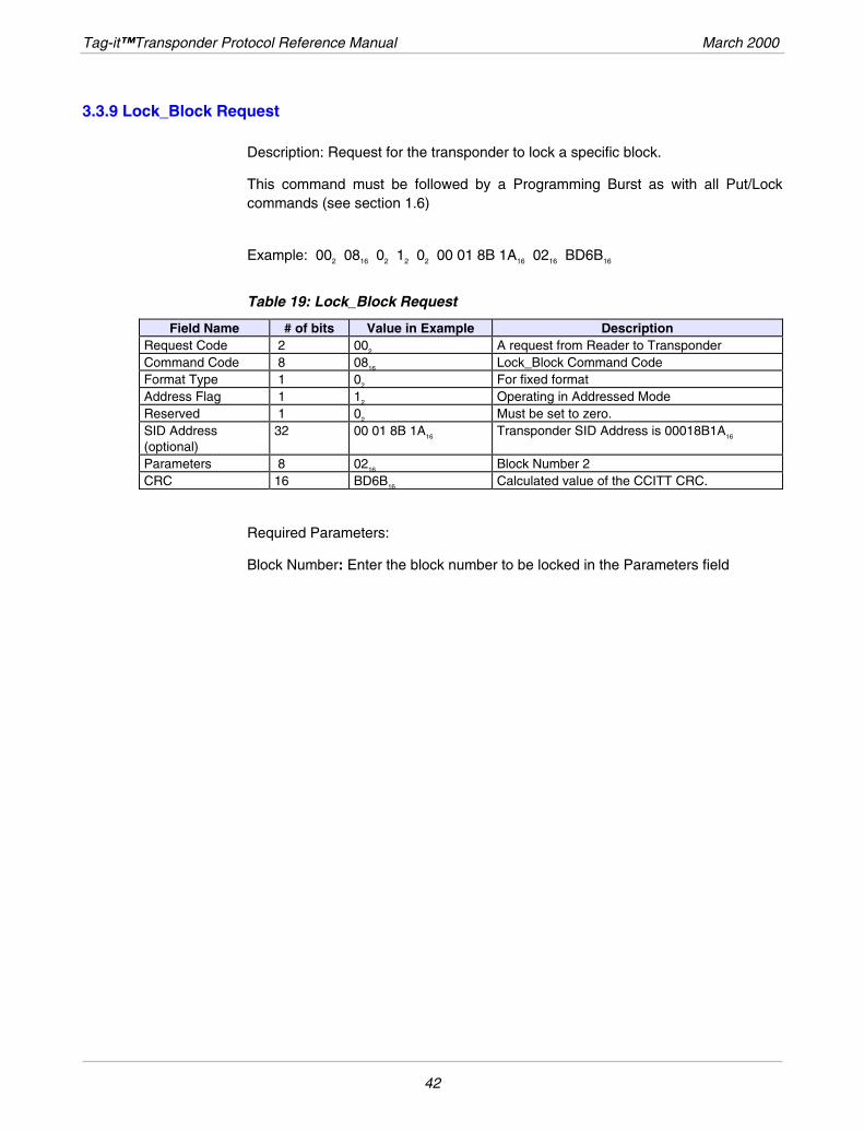
3.3.9 Lock_Block Request
Description: Request for the transponder to lock a specific block.
This command must be followed by a Programming Burst as with all Put/Lock commands (see section 1.6)
Example: 002 0816 02 12 02 00 01 8B 1A16 0216 BD6B16
Table 19: Lock_Block Request
Field Name # of bits Value in Example Description Request Code 2 002 A request from Reader to Transponder Command Code 8 0816 Lock_Block Command Code Format Type 1 02 For fixed format Address Flag 1 12 Operating in Addressed Mode Reserved 1 02 Must be set to zero. SID Address (optional)
32 00 01 8B 1A16 Transponder SID Address is 00018B1A16
Parameters 8 0216 Block Number 2 CRC 16 BD6B16 Calculated value of the CCITT CRC.
Required Parameters:
Block Number: Enter the block number to be locked in the Parameters field
42
March 2000 List of Commands
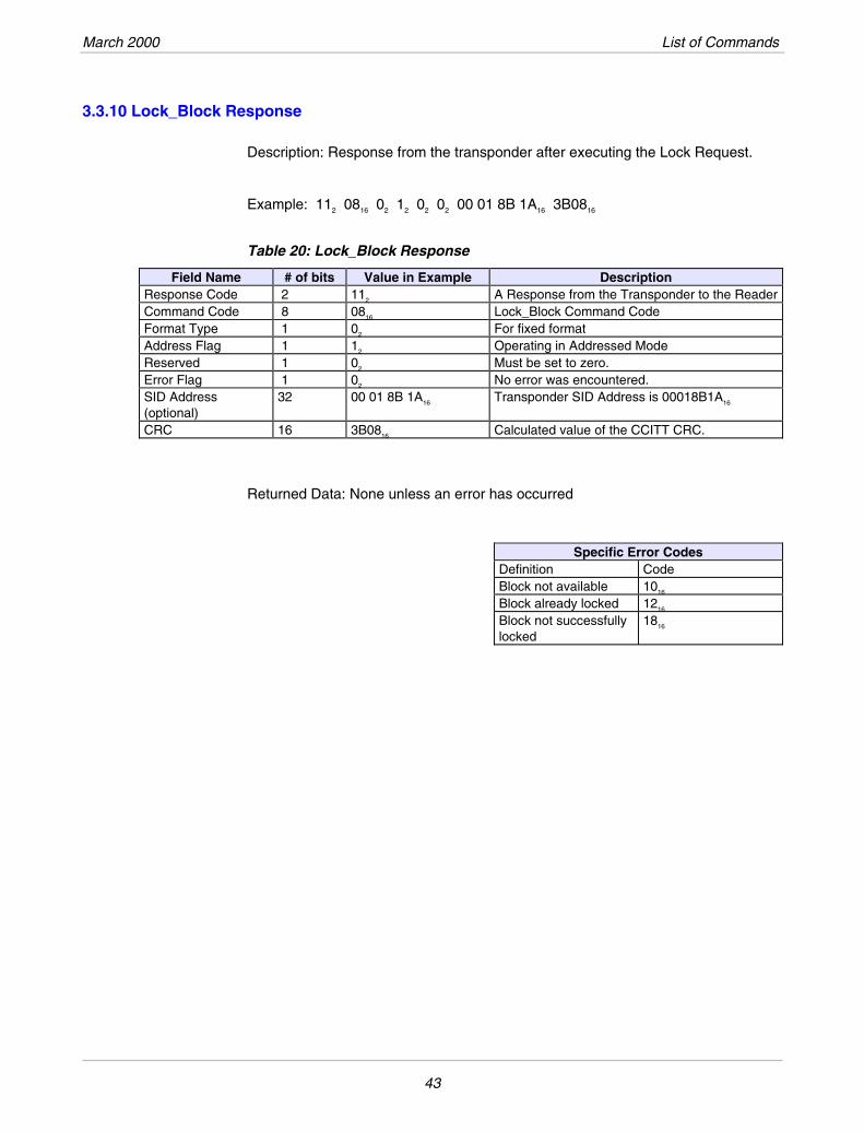
3.3.10 Lock_Block Response
Description: Response from the transponder after executing the Lock Request.
Example: 112 0816 02 12 02 02 00 01 8B 1A16 3B0816
Table 20: Lock_Block Response
Field Name # of bits Value in Example Description Response Code 2 112 A Response from the Transponder to the ReaderCommand Code 8 0816 Lock_Block Command Code Format Type 1 02 For fixed format Address Flag 1 12 Operating in Addressed Mode Reserved 1 02 Must be set to zero. Error Flag 1 02 No error was encountered. SID Address (optional)
32 00 01 8B 1A16 Transponder SID Address is 00018B1A16
CRC 16 3B0816 Calculated value of the CCITT CRC.
Returned Data: None unless an error has occurred
Specific Error Codes Definition Code Block not available 1016
Block already locked 1216
Block not successfully locked
1816
43
Tag-it™Transponder Protocol Reference Manual March 2000
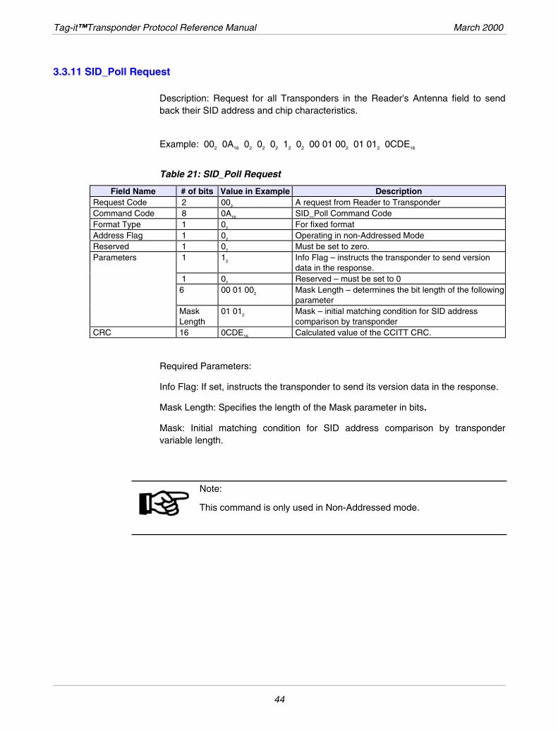
3.3.11 SID_Poll Request
Description: Request for all Transponders in the Reader's Antenna field to send back their SID address and chip characteristics.
Example: 002 0A16 02 02 02 12 02 00 01 002 01 012 0CDE16
Table 21: SID_Poll Request
# of bits Value in Example Description Field Name Request Code 2 002 A request from Reader to Transponder Command Code 8 0A16 SID_Poll Command Code Format Type 1 02 For fixed format Address Flag 1 02 Operating in non-Addressed Mode Reserved 1 02 Must be set to zero. Parameters 1 12 Info Flag – instructs the transponder to send version
data in the response. 1 02 Reserved – must be set to 0 6 00 01 002 Mask Length – determines the bit length of the following
parameter Mask
Length 01 012 Mask – initial matching condition for SID address
comparison by transponder CRC 16 0CDE16 Calculated value of the CCITT CRC.
Required Parameters:
Info Flag: If set, instructs the transponder to send its version data in the response.
Mask Length: Specifies the length of the Mask parameter in bits.
Mask: Initial matching condition for SID address comparison by transponder variable length.
Note: This command is only used in Non-Addressed mode.
44
March 2000 List of Commands
3.3.12 SID_Poll Response
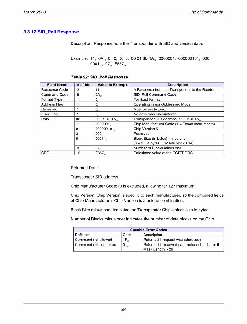
Description: Response from the Transponder with SID and version data.
Example: 112 0A16 02 02 02 02 00 01 8B 1A16 00000012 0000001012 0002 000112 0716 F85716
Table 22: SID_Poll Response
Field Name # of bits Value in Example Description Response Code 2 112 A Response from the Transponder to the Reader Command Code 8 0A16 SID_Poll Command Code Format Type 1 02 For fixed format Address Flag 1 02 Operating in non-Addressed Mode Reserved 1 02 Must be set to zero. Error Flag 1 02 No error was encountered. Data 32 00 01 8B 1A16 Transponder SID Address is 00018B1A16
7 00000012 Chip Manufacturer Code (1 = Texas Instruments) 9 0000001012 Chip Version 5 3 0002 Reserved 5 000112 Block Size (in bytes) minus one
(3 + 1 = 4 bytes = 32 bits block size) 8 0716 Number of Blocks minus one CRC 16 F85716 Calculated value of the CCITT CRC.
Returned Data:
Transponder SID address
Chip Manufacturer Code: (0 is excluded, allowing for 127 maximum)
Chip Version: Chip Version is specific to each manufacturer, so the combined fields of Chip Manufacturer + Chip Version is a unique combination.
Block Size minus one: Indicates the Transponder Chip’s block size in bytes.
Number of Blocks minus one: Indicates the number of data blocks on the Chip.
Specific Error Codes Definition Code Description Command not allowed 1F16 Returned if request was addressed Command not supported 0116 Returned if reserved parameter set to 12 , or if
Mask Length > 28
45
Tag-it™Transponder Protocol Reference Manual March 2000
3.3.13 Quiet Request
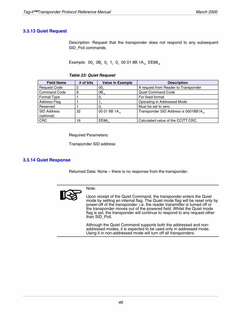
Description: Request that the transponder does not respond to any subsequent SID_Poll commands.
Example: 002 0B6 02 12 02 00 01 8B 1A16 EE8816
Table 23: Quiet Request
Field Name # of bits Value in Example Description Request Code 2 002 A request from Reader to Transponder Command Code 8 0BB16 Quiet Command Code Format Type 1 02 For fixed format Address Flag 1 12 Operating in Addressed Mode Reserved 1 02 Must be set to zero. SID Address (optional)
32 00 01 8B 1A16 Transponder SID Address is 00018B1A16
CRC 16 EE8816 Calculated value of the CCITT CRC.
Required Parameters:
Transponder SID address
3.3.14 Quiet Response
Returned Data: None – there is no response from the transponder.
Note: Upon receipt of the Quiet Command, the transponder enters the Quiet mode by setting an internal flag. The Quiet mode flag will be reset only by power-off of the transponder, i.e. the reader transmitter is turned off or the transponder moves out of the powered field. Whilst the Quiet mode flag is set, the transponder will continue to respond to any request other than SID_Poll. Although the Quiet Command supports both the addressed and non-addressed modes, it is expected to be used only in addressed mode. Using it in non-addressed mode will turn off all transponders.
46
March 2000 List of Commands
3.4 SID Mechanism
The SID_Poll Request is different to all other requests, in that it is completed by a managed sequence of power bursts, interrupted by pauses.
The SID polling mechanism has some similarity with the concept designed into the ALOHA network by the University of Hawaii in 1969, in the version referred to as “discrete random packet broadcasting”.
It differs however in many respects, the main ones being:
Transponders (stations in the Aloha network) transmit their answer only when they are polled.
The polling mechanism is selective.
The time slots during which transponders can answer are specified by the reader, by the mean of interruption (SID pause) in the emission of the carrier frequency.
Within a given time slot, transponders answer only if there is a match between their unique factory-programmed SID address and the SID_Poll Request, according to well defined rules based on the mask parameter specified by the reader.
As the time slots are “clocked” by the reader, the total duration of the SID_Poll Command execution is optimized to the number of transponders in the field. The SID_Poll Request is followed by a sequence of long power bursts, pauses and short power bursts.
Power-up Sequence: As described earlier, before transmitting the SID_Poll Request, the reader performs a power-up pulse to supply all the tags within its interrogation field with enough initial power. The duration of this pulse is specified in the transponder IC datasheet.
47
Tag-it™Transponder Protocol Reference Manual March 2000
3.4.1 SID_Poll Request:
Read Short Phase (trs): When no tag response is received by the reader (e.g. start of frame or 10 consecutive bits), the system stops transmitting and generates the next pause.
Read Long Phase (trl): If the system detects within the Read Short Phase a tag signal and a valid Start of Frame pattern (SOF), it extends the power transmission up to a maximum time (trl) or until the End of Frame (EOF) pattern has been received.
SID Pause (tp): The end of each of the SID sequences (power phases) will be marked by a pause. This pause will be used by the tags as the trigger to enable the execution of an action or a command (e.g. command to increase the transponder SID_Address, or latch the received data and compare).
At the beginning of a read cycle the reader transmits the Power-Up sequence followed by a SID Command. In order to send commands the reader modulates the RF signal to transmit the encoded Downlink data. Between two SID-pause phases the reader transmits the power signal continuously to supply the tag with energy and a system clock. The receiver is active during this time and samples the data input to receive the incoming data from the tag. The length of these SID pulses depends on whether a tag is in the field or not. If during a time frame of (for example) trs
* the receiver does not receive any valid data, the reader ceases the transmission to generate the next pause to increase the transponder address counter. If during the trs time frame the receiver detects the Start of Frame pattern and/or a number of valid consecutive bits the power transmission will be prolonged up to a maximum time frame (trl
*) or in case of real-time processing until the End of Frame pattern is detected.
The SID mechanism consists of 4 elements:
the SID_Poll Request, including its parameters, sent by the reader
the Request processing performed by the transponder
the Collision Detection performed by the reader
the Collision Management Algorithm performed by the reader
The Reader talks first. Any transponder talks only when so instructed.
48
March 2000 List of Commands
3.4.2 SID_Poll Request Parameters
The SID_Poll Request sent by the reader to the transponders contains 2 parameters:
• mask length
• mask value
The mask length and value are set by the reader according to the algorithm described below.
The mask is used to selectively address the subset(s) of transponders having previously generated a collision.
The Request is followed by a series of 16 pauses (short interruptions of carrier), the time interval between 2 subsequent pauses varies as explained above. The 16 pauses allow time to analyze a 4-bit field. This value is believed to offer the best performance for the number of transponders which can be reasonably present in the reader field of interrogation (between 1 and 100).
3.4.3 SID_Poll Request processing by transponder
On receipt of a Request, each VICC stores the mask value and the mask length into the mask register. It also clears its sub-address counter.
The mask register and the sub-address counter are fed into a comparator with the transponder address.
Note: As explained in the algorithm description below, in the first request of an inventory cycle, the mask length is null, thus the sub-address counter is compared to the 4 LSB of the transponder address.
The transponder then counts the pauses. Upon the detection of a pause, the VICC stops any current transmission of an ATQ, it increments it sub-address counter, it compares the bits contained in the sub-address counter and in the previously stored mask to the corresponding bits of its address (the “don’t care” bits of the address are ignored),
if a match is found, it sends back an ATQ (containing its address), otherwise (if no match is found) it stays quiet.
49
Tag-it™Transponder Protocol Reference Manual March 2000
3.5 Collision Detection
Immediately after having generated a Pause, the reader listens for possible reception of responses sent by transponders present.
Several situations may occur:
No signal can be detected: This means that no transponder matching the current criteria (mask & sub-address) is present in the field. The reader then generates the next Pause. As this detection can be done in a very short time (approximately 1ms), this speeds up the whole process.
A signal is detected: The reader extends the carrier powering and receives the Response(s).
A collision is detected: This means that more than one transponder match the current criteria (mask & sub-address) and have sent back their response. The reader then generates the next Pause, without waiting for the full transmission of the responses. This Pause will stop transmission of any transponder, as described above. This also speeds up the process.
No collision is detected: The reader extends the carrier powering until reception of a complete frame, or until a time-out elapses.
Two cases may occur:
An OK response is received ( validated CRC).
A frame is received with errors (bad CRC, etc.). This is handled by the algorithm as if a collision was detected (see above).
50
March 2000 List of Commands
3.5.1 Collision Management Algorithm
Using the three mechanisms described above, the Collision Management Algorithm is executed by the VCD and manages detected collisions, so that all VICCs are selectively interrogated such that at some stage only one VICC will be selectively addressed and thus will be the only one to answer.
The algorithm is described below in pseudo-code and uses recursivity for the sake of efficiency and clarity of programming. Other implementations are possible.
Function push (mask, address); pushes on private stack
Function pop (mask, address); pops from private stack
Function pulse_next_pause; generates a power pulse
Function store(VICC_id); stores inventoried VICC; address (identifier)
Function poll_loop (sub_address_size as integer)
Pop (mask, address)
Mask = address & mask; generates new mask
; send the request
send_Request(Request_cmd, mask length, mask value) for sub_address = 0 to (2^sub_address_size - 1)
pulse_next_pause
if no_collision_is_detected then
; VICC is inventoried
store (VICC_id)
else
; remember a collision was detected
push(mask,address)
endif next sub_address
; if some collisions have been detected and not yet processed,
; the function calls itself recursively to process the last
; stored collision
if stack_not_empty then poll_loop (sub_address_size)
end poll_loop
51
Tag-it™Transponder Protocol Reference Manual March 2000
main_cycle:
mask = null
address = null
push (mask, address)
poll_loop(sub_address_size)
end_main_cycle
52
March 2000 List of Commands
3.6 CRC
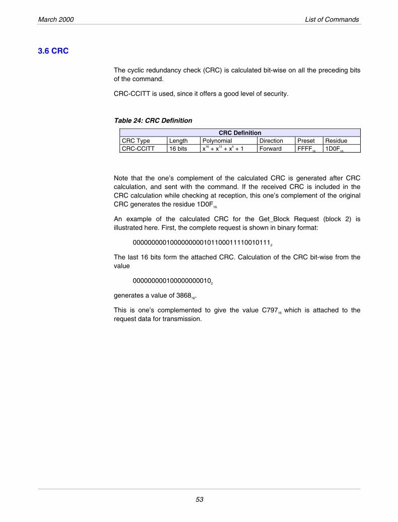
The cyclic redundancy check (CRC) is calculated bit-wise on all the preceding bits of the command.
CRC-CCITT is used, since it offers a good level of security.
Table 24: CRC Definition
CRC Definition CRC Type Length Polynomial Direction Preset Residue
x16 + x12 + x5 + 1 Forward CRC-CCITT 16 bits FFFF16 1D0F16
Note that the one’s complement of the calculated CRC is generated after CRC calculation, and sent with the command. If the received CRC is included in the CRC calculation while checking at reception, this one’s complement of the original CRC generates the residue 1D0F16.
An example of the calculated CRC for the Get_Block Request (block 2) is illustrated here. First, the complete request is shown in binary format:
00000000010000000001011000111100101112
The last 16 bits form the attached CRC. Calculation of the CRC bit-wise from the value
0000000001000000000102
generates a value of 386816.
This is one’s complemented to give the value C79716 which is attached to the request data for transmission.
53
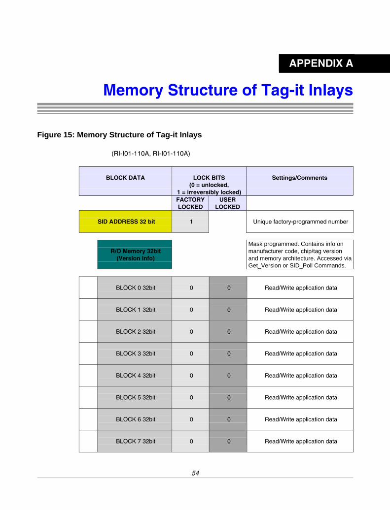
Memory Structure of Tag-it Inlays Figure 15: Memory Structure of Tag-it Inlays
(RI-I01-110A, RI-I01-110A)
BLOCK DATA
LOCK BITS (0 = unlocked,
1 = irreversibly locked)
Settings/Comments
FACTORYLOCKED
USER LOCKED
SID ADDRESS 32 bit
1 Unique factory-programmed number
Mask programmed. Contains info on manufacturer code, chip/tag version and memory architecture. Accessed via Get_Version or SID_Poll Commands.
R/O Memory 32bit
(Version Info)
BLOCK 0 32bit
0 0 Read/Write application data
BLOCK 1 32bit
0 0 Read/Write application data
BLOCK 2 32bit
0 0 Read/Write application data
BLOCK 3 32bit
0 0 Read/Write application data
BLOCK 4 32bit
0 0 Read/Write application data
BLOCK 5 32bit
0 0 Read/Write application data
BLOCK 6 32bit
0 0 Read/Write application data
BLOCK 7 32bit
0 0 Read/Write application data
APPENDIX A
54
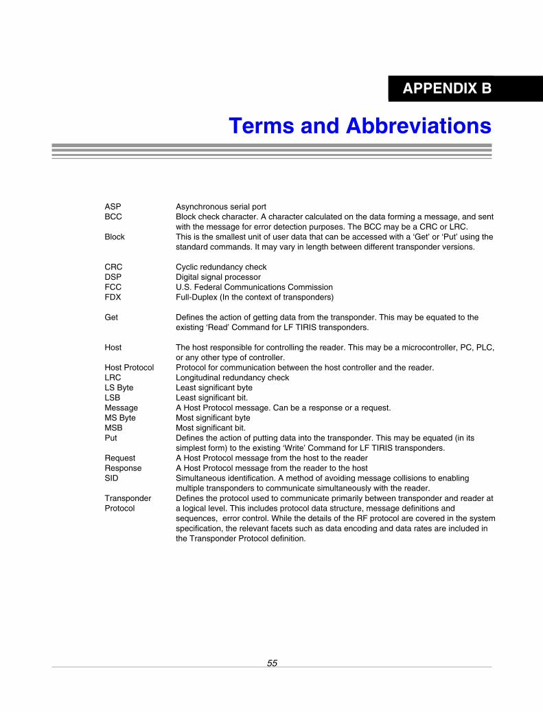
APPENDIX B
Terms and Abbreviations
ASP Asynchronous serial port BCC Block check character. A character calculated on the data forming a message, and sent
with the message for error detection purposes. The BCC may be a CRC or LRC. Block This is the smallest unit of user data that can be accessed with a ‘Get’ or ‘Put’ using the
standard commands. It may vary in length between different transponder versions.
CRC Cyclic redundancy check DSP Digital signal processor FCC U.S. Federal Communications Commission FDX Full-Duplex (In the context of transponders)
Get Defines the action of getting data from the transponder. This may be equated to the
existing ‘Read’ Command for LF TIRIS transponders.
Host The host responsible for controlling the reader. This may be a microcontroller, PC, PLC, or any other type of controller.
Host Protocol Protocol for communication between the host controller and the reader. LRC Longitudinal redundancy check LS Byte Least significant byte LSB Least significant bit. Message A Host Protocol message. Can be a response or a request. MS Byte Most significant byte MSB Most significant bit. Put Defines the action of putting data into the transponder. This may be equated (in its
simplest form) to the existing ‘Write’ Command for LF TIRIS transponders. Request A Host Protocol message from the host to the reader Response A Host Protocol message from the reader to the host SID Simultaneous identification. A method of avoiding message collisions to enabling
multiple transponders to communicate simultaneously with the reader. Transponder Protocol
Defines the protocol used to communicate primarily between transponder and reader at a logical level. This includes protocol data structure, message definitions and sequences, error control. While the details of the RF protocol are covered in the system specification, the relevant facets such as data encoding and data rates are included in the Transponder Protocol definition.
55