tac xenta family v3 - tbnpro.ru filetac xenta family v3 engineering guidelines contents tac ab,...
TRANSCRIPT
0-004-7639-0 (GB), 1998-08-15
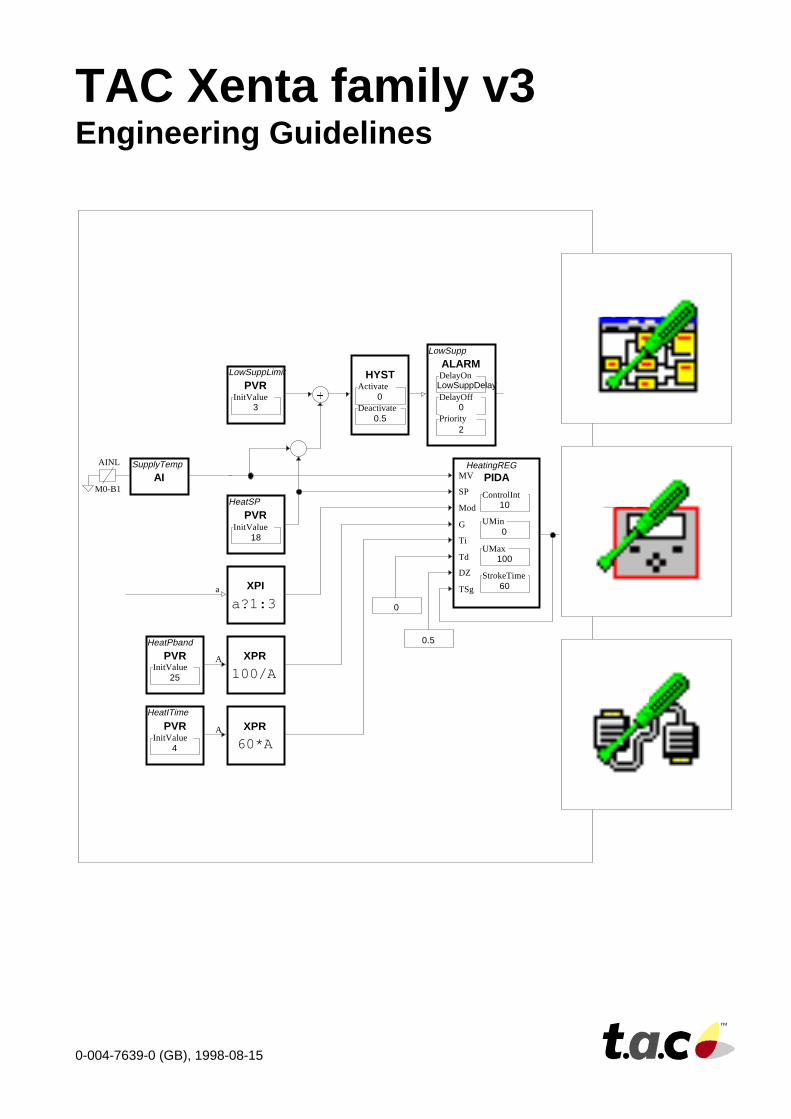
TAC Xenta family v3Engineering Guidelines
XPR
60*AA
�
PVRLowSuppLimit
InitValue3
XPR
100/AA
ALARMLowSupp
DelayOff0
Priority2
HYST
0Deactivate
0.5
�
AISupplyTempAINL
M0-B1
PVRHeatSP
InitValue18
XPI
a?1:3a
PVRHeatPband
InitValue25
PVRHeatITime
InitValue4
0
0.5
PIDAHeatingREG
ControlInt10
UMin0
UMax100
StrokeTime60
MV
SP
Mod
G
Ti
Td
DZ
TSg
LowSuppDelayDelayOn
Activate
ForewordWelcome to the TAC Xenta family v3 Engineering Guidelines.
Copyright © 1998 TAC AB.
Subject to modification.
This document, as well as the product it refers to, is only intended for licensed users of the product and the document. TAC AB ownsthe copyright of this document and reserves the right to make changes, additions or deletions. TAC AB assumes no responsibility forpossible mistakes or errors that might appear in this document.
Do not use the product for any other purposes than those indicated in this document.
Only licensed users of the product and the document are permitted to use the document or any information therein. Distribution,disclosure, copying, storing or use of the product, the information or the illustrations in the document on the part of non-licensed users,in electronic or mechanical form, as a recording or by other means, including photocopying or information storage and retrievalsystems, without the express written permission of TAC AB, will be regarded as a violation of copyright laws and is strictly prohibited.
TAC Vista, TAC Menta and TAC Xenta are registered trademarks of TAC AB in Sweden and other countries. All other brand namesare trade marks of their respective owners.
Revisions
Art No Comment Editor Date0-004-7639-0 First version. CPHA 1998-08-15
Covers TAC Menta version 3.1, TAC Vista version 3.1 and TAC Xenta version 3.1.

TAC Xenta family v3 Engineering Guidelines Contents
TAC AB, 1998-08-15 0-004-7639-0 (GB)
TAC Xenta family v3Engineering Guidelines
Contents
1. Introduction 1-11.1. Purpose.................................................................................................................................. 1-1
1.2. Terminology........................................................................................................................... 1-1
1.3. Overall way of working.......................................................................................................... 1-2
1.4. More information................................................................................................................... 1-3
2. Basic project analysis 2-12.1. System configuration.............................................................................................................. 2-12.1.1. Operator units....................................................................................................................... 2-12.1.2. The LonWorks network........................................................................................................ 2-1
2.2. Point identification/Allocation................................................................................................ 2-22.2.1. Standard applications............................................................................................................ 2-22.2.2. Execution............................................................................................................................. 2-32.2.3. Standard for TAC Xenta 300 point allocation........................................................................ 2-5
2.3. Acronyms and ID's................................................................................................................ 2-62.3.1. General structure.................................................................................................................. 2-62.3.2. Create ID in TAC Menta....................................................................................................... 2-72.3.3. Display the ID...................................................................................................................... 2-72.3.4. Physical ID........................................................................................................................... 2-9
3. Programming 3-13.1. Preparations........................................................................................................................... 3-13.1.1. Environment and Tools......................................................................................................... 3-13.1.2. Program licenses................................................................................................................... 3-23.1.3. Folder structure.................................................................................................................... 3-2
3.2. Application programming...................................................................................................... 3-33.2.1. FBD programming................................................................................................................ 3-33.2.2. The Macro Block Library..................................................................................................... 3-53.2.3. OP configuration.................................................................................................................. 3-73.2.4. User documentation.............................................................................................................. 3-8
3.3. TAC Vista.............................................................................................................................. 3-93.3.1. General................................................................................................................................. 3-93.3.2. Database generator............................................................................................................... 3-93.3.3. Colour graphics.................................................................................................................... 3-93.3.4. Reports and presentations................................................................................................... 3-103.3.5. General working method..................................................................................................... 3-11
TAC Xenta family v3 Engineering Guidelines Contents
0-004-7639-0 (GB) TAC AB, 1998-08-15
3.3.6. Creating a database for TAC Xenta units............................................................................ 3-113.3.7. System documentation........................................................................................................ 3-123.3.8. Backup............................................................................................................................... 3-12
3.4. Upgrading............................................................................................................................ 3-133.4.1. Upgrading the TAC Xenta units.......................................................................................... 3-133.4.2. Upgrading the TAC Vista database..................................................................................... 3-13
4. Commissioning 4-14.1. Commissioning with TAC Menta.......................................................................................... 4-14.1.1. Initial checking..................................................................................................................... 4-14.1.2. Network configuration.......................................................................................................... 4-24.1.3. I/O test ................................................................................................................................. 4-44.1.4. Functional test...................................................................................................................... 4-5
Index
Reply form
This document has 44 pages

TAC Xenta family v3 Engineering Guidelines Introduction
TAC AB, 1998-08-15 0-004-7639-0 (GB), 1:1 (3)
1. Introduction1.1. Purpose
This document describes tools and working methods in the TAC Xentafamily (TAC Xenta, TAC Menta and TAC Vista), both hardware andsoftware, that are or could be useful when executing the different tasksin the contracting business. In the document, working methods areproposed and available tools to support them are shown. Also, it will inshort describe how to use the tools. All to enable or facilitate the scoopof work within the contracting cycle.
1.2. TerminologyThe following TAC Xenta family terminology is used in this document:
TAC Xenta A standard controller or a freely programmableunit with modular I/O configuration.
OP Operator Panel on the TAC Xenta unit.
LONWORKS™ The standardised network, used forcommunication between the TAC Xenta units.
TAC Vista A PC based operator unit for monitoring andcontrol of air handling and heating systems.
TAC Menta Application programming tool for TAC Xenta.
OP configuration Programming tool for the TAC Xenta Operatortool panel, included in TAC Menta.
Network Tool for definition of the TAC Xenta unitsconfiguration tool network addresses etc., included in TAC Menta.
The following abbreviations and acronyms, not explained where theyoccur, are used throughout the document:
ASCII American Standard Code for InformationInterchange.
BMS Building Management System
HVAC Heating, Ventilation & Air Conditioning
ID Plant specific names/descriptors for points etc.
I/O Input/Output
TAC Xenta family v3 Engineering Guidelines Introduction
0-004-7639-0 (GB), 1:2 (3) TAC AB, 1998-08-15
1.3. Overall way of workingThe overall way of working in a BMS project can be divided into threeparts, which also give the different chapters in this Guideline theirnames:
Chapter 2 Basic project analysisChapter 3 ProgrammingChapter 4 Commissioning
All three parts should be used by all personnel involved in thecontracting business, especially Chapter 2, because if this area isneglected, it will be hard to compensate for it later on in the project.
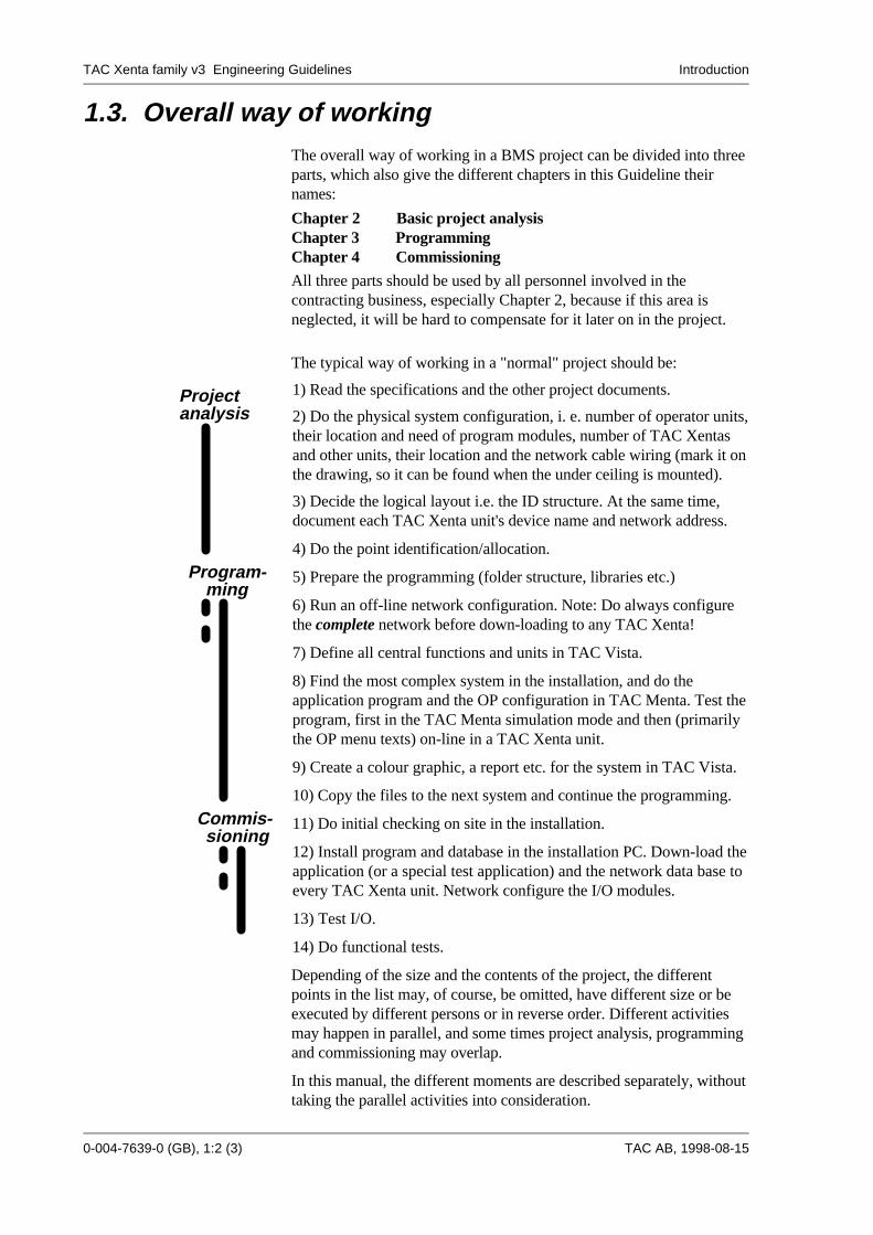
The typical way of working in a "normal" project should be:
1) Read the specifications and the other project documents.
2) Do the physical system configuration, i. e. number of operator units,their location and need of program modules, number of TAC Xentasand other units, their location and the network cable wiring (mark it onthe drawing, so it can be found when the under ceiling is mounted).
3) Decide the logical layout i.e. the ID structure. At the same time,document each TAC Xenta unit's device name and network address.
4) Do the point identification/allocation.
5) Prepare the programming (folder structure, libraries etc.)
6) Run an off-line network configuration. Note: Do always configurethe complete network before down-loading to any TAC Xenta!
7) Define all central functions and units in TAC Vista.
8) Find the most complex system in the installation, and do theapplication program and the OP configuration in TAC Menta. Test theprogram, first in the TAC Menta simulation mode and then (primarilythe OP menu texts) on-line in a TAC Xenta unit.
9) Create a colour graphic, a report etc. for the system in TAC Vista.
10) Copy the files to the next system and continue the programming.
11) Do initial checking on site in the installation.
12) Install program and database in the installation PC. Down-load theapplication (or a special test application) and the network data base toevery TAC Xenta unit. Network configure the I/O modules.
13) Test I/O.
14) Do functional tests.
Depending of the size and the contents of the project, the differentpoints in the list may, of course, be omitted, have different size or beexecuted by different persons or in reverse order. Different activitiesmay happen in parallel, and some times project analysis, programmingand commissioning may overlap.
In this manual, the different moments are described separately, withouttaking the parallel activities into consideration.
Projectanalysis
Program-ming
Commis-sioning
TAC Xenta family v3 Engineering Guidelines Introduction
TAC AB, 1998-08-15 0-004-7639-0 (GB), 1:3 (3)
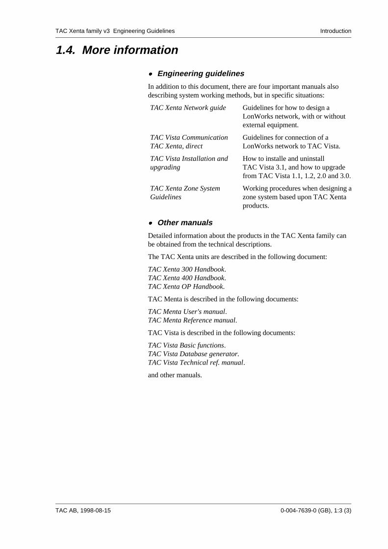
1.4. More information
x�x� Engineering guidelines
In addition to this document, there are four important manuals alsodescribing system working methods, but in specific situations:
TAC Xenta Network guide Guidelines for how to design aLonWorks network, with or withoutexternal equipment.
TAC Vista CommunicationTAC Xenta, direct
Guidelines for connection of aLonWorks network to TAC Vista.
TAC Vista Installation andupgrading
How to installe and uninstallTAC Vista 3.1, and how to upgradefrom TAC Vista 1.1, 1.2, 2.0 and 3.0.
TAC Xenta Zone SystemGuidelines
Working procedures when designing azone system based upon TAC Xentaproducts.
x�x� Other manuals
Detailed information about the products in the TAC Xenta family canbe obtained from the technical descriptions.
The TAC Xenta units are described in the following document:
TAC Xenta 300 Handbook.TAC Xenta 400 Handbook.TAC Xenta OP Handbook.
TAC Menta is described in the following documents:
TAC Menta User's manual.TAC Menta Reference manual.
TAC Vista is described in the following documents:
TAC Vista Basic functions.TAC Vista Database generator.TAC Vista Technical ref. manual.
and other manuals.

TAC AB, 1997-xx-xx
Produkt version X, Manualens namn Svarsblankett
TAC Xenta family v3 Engineering Guidelines Basic project analysis
TAC AB, 1998-08-15 0-004-7639-0 (GB), 2:1 (10)
2. Basic project analysisThe basic project analysis contains some planning activities, whichhighly affect the engineering hours needed later in the project.
2.1. System configurationSystem configuration deals with the physical and logical lay-out of theHVAC system: where to place Operator units, TAC Xenta units, andhow to connect them. This, of course, must be done in an early stage ofthe project.
2.1.1. Operator units
The networks function (N1 network) in TAC Vista makes it possible tocreate a system for large or geographically ‘spread-out’ plants. Thenetwork is usually established by direct connections between severaloperator units in a local area network (LAN). From any operator unitthe operator has through the network access to resources, processunitsand all objects in the distributed database, as if they were stored on theoperator unit which he has logged on to. Printers can be connected toeach operator unit for printing of graphics, alarms, reports etc.
The network functions are described in a separate manual; TAC VistaNetworks. How to define nodes in TAC Vista is also described in TACVista Basic Functions.
2.1.2. The LonWorks network
TAC Xenta units communicate with each other, the Xenta OP and theTAC Vista operator units via the Echelon LONWORKS™ network (N2network). When designing the network, a lot of things such as networktopology, cable lengths, need of extra units for signal amplifica-tion/traffic sectioning etc. have to be taken into consideration. How todo this design is described in the TAC Xenta Network guide.
Always read the Network guide, also when the network is limited to I/Omodule and OP communication!
Note. The LONWORKS™ network can also be used by devices fromother manufacturers forming e.g. light control systems or alarmsystems. No matter if these system works in parallel with the HVACsystem, or if they are integrated, co-operation is not only important, butnecessary to make the systems work at all!
TAC Xenta family v3 Engineering Guidelines Basic project analysis
0-004-7639-0 (GB), 2:2 (10) TAC AB, 1998-08-15
2.2. Point identification/AllocationThe importance of a good point allocation is often underestimated.There is a very close connection between how well the allocation isdone and the efficiency that can be achieved later in the project.
With a good allocation, copying techniques can substantially reduce theengineering hours needed for design/manufacturing of electrical panels,which lowers the project cost. Installation and commissioning work ispositively affected if the point allocation is done in an efficient way. Ifstandards are followed, and the same point allocation principles areused for HVAC units with similar function, the commissioning and testhours can be reduced. There will also be less risk of making errors andit will be easier to find and correct the faults that are made.
The documents you base your identification/allocation on, are normallyproduced by someone outside your company e.g. a Consult Engineer ora Mechanical contractor. Their main objective when producing thesedocuments is to describe the system as a HVAC function. It is not todescribe and allocate I/O signals and devices in accordance withcontrollers, RPUs and other products from a certain manufacturer.
It is your task to translate their HVAC functions into physical systemlayouts. This work should really start already when the quotation isprepared and submitted. Therefore, even if described in the consultantsdocuments, you should not just accept the allocation of points. Alwaysconsider the solution from a project execution point of view, using yourintelligence and knowledge to make an "optimal" point allocation.
Sometimes there are points related to the security of the installation orof the user and where the allocation is specified as a requirement fromsome authority e.g. fire authorities or insurance companies etc. In suchcases you should of course comply with the specification.
Often functions specified as hard-wire interlocked or as a function froma special device, can be carried out in software programming, withoutaffecting the reliability/quality of the project. Normally your costs canbe reduced and your profit increased if such a solution can be utilised.
Always look for possibilities like that and try to get them accepted bythe persons responsible for the specification. Of course you shouldnever alter these things without a discussion and an agreement fromthem. Any changes must be proposed and documented prior to thesigning of the contract, or stated as a clarification in your offer for theproject.
To summarise: a good point allocation saves money in a project fromthe start. A bad allocation will cost money and once you have had it,your possibilities to improve later during the project will be limited.
2.2.1. Standard applications
The optimum solution is to use complete standard applications forwhole units where the I/O allocation are fixed in a TAC Xenta unit,where the colour graphic is standardised and where the function of thewhole application is fixed. These standards should be proposed to the
TAC Xenta family v3 Engineering Guidelines Basic project analysis
TAC AB, 1998-08-15 0-004-7639-0 (GB), 2:3 (10)
customer already in the sales phase and offered instead of the specifiedfunctions and solutions, and will affect the price in a positive way.
In this way of working in your market place, a library of suchstandards should be compiled and well documented and not the least,introduced both to your own sales engineers and to your customers.
Please note! The whole idea is to sell your standard solutions withoutany alterations. As soon as you do any changes to "standard" you willhave to spend engineering hours and this will increase the price to thesame level as a non standard application. Therefore, you shall alwayskeep the list of available standard applications updated and knowwhere to find them.
2.2.2. Execution
1. You begin by identifying the various systems in the specification andtheir physical location. By "system" is meant an AHU, a heater etc.
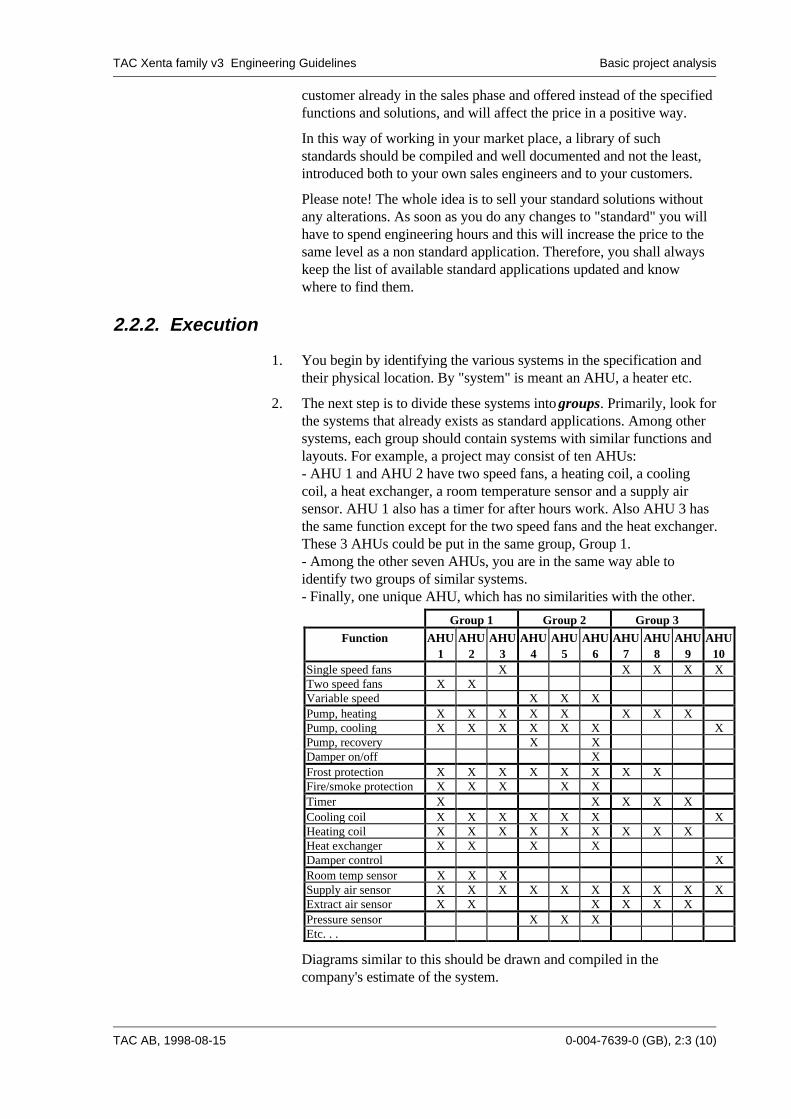
2. The next step is to divide these systems into groups. Primarily, look forthe systems that already exists as standard applications. Among othersystems, each group should contain systems with similar functions andlayouts. For example, a project may consist of ten AHUs:- AHU 1 and AHU 2 have two speed fans, a heating coil, a coolingcoil, a heat exchanger, a room temperature sensor and a supply airsensor. AHU 1 also has a timer for after hours work. Also AHU 3 hasthe same function except for the two speed fans and the heat exchanger.These 3 AHUs could be put in the same group, Group 1.- Among the other seven AHUs, you are in the same way able toidentify two groups of similar systems.- Finally, one unique AHU, which has no similarities with the other.
Group 1 Group 2 Group 3
Function AHU1
AHU2
AHU3
AHU4
AHU5
AHU6
AHU7
AHU8
AHU9
AHU10
Single speed fans X X X X XTwo speed fans X XVariable speed X X XPump, heating X X X X X X X XPump, cooling X X X X X X XPump, recovery X XDamper on/off XFrost protection X X X X X X X XFire/smoke protection X X X X XTimer X X X X XCooling coil X X X X X X XHeating coil X X X X X X X X XHeat exchanger X X X XDamper control XRoom temp sensor X X XSupply air sensor X X X X X X X X X XExtract air sensor X X X X X XPressure sensor X X XEtc. . .
Diagrams similar to this should be drawn and compiled in thecompany's estimate of the system.

TAC Xenta family v3 Engineering Guidelines Basic project analysis
0-004-7639-0 (GB), 2:4 (10) TAC AB, 1998-08-15
Further, there are two heating applications for the different parts of thebuilding, that are similar and could be put in one heating group. Thereare also two chiller applications that can be regarded as one group.
3. After having identified the five groups, you start the actual pointallocation. Start with the system that contains the most complexfunctions. This system shall then always be used as a master, evenwhen you create a new master for a similar type of system.
In this case, select one of the two speed systems in Group 1 as masterwhen copying for the other systems in this group.
Allocate the corresponding I/O in this TAC Xenta unit in accordancewith the standards in section 2.2.3. Make sure that all points andnecessary hardware devices are included in your design. If at a laterstage you have to add some points, the layout of the point allocationbecomes unstructured and will in a negative way affect the subsequentwork with the project.
Be careful when you design the master. If you spend some extra timehere, you will gain this many times over when working with copies.
4. When the point allocation for the master is done, make one copy forAHU 2 and one for AHU 3. For the single speed unit, leave the pointsused for switching between low and high speed, the timer and the heatexchanger empty for the time being.
Always keep the basic layout of the master intact. This is important forcommissioning and maintenance. If you for some reason remove I/Opoints, or as in this case do not need them, avoid compressing theremaining points. If you do this, in order not to get idle points in themiddle, the copying advantages will be reduced.
5. Complete the other systems in the group and add any signals unique forthe units.
6. Continue with the next group using the same methodology. Do notforget to always copy from your origin master!
7. When all the systems have been arranged into TAC Xenta units,allocate the remaining alarms and sensors etc. to the most appropriateTAC Xenta unit. In this way you will use the "idle points" describedabove and at the same time not destroy your copying advantages.
8. Check that all associated functions are placed in the same TAC Xentaunit as far as possible.
TAC Xenta family v3 Engineering Guidelines Basic project analysis
TAC AB, 1998-08-15 0-004-7639-0 (GB), 2:5 (10)
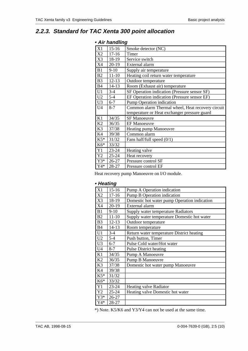
2.2.3. Standard for TAC Xenta 300 point allocation
• Air handlingX1 15-16 Smoke detector (NC)X2 17-16 TimerX3 18-19 Service switchX4 20-19 External alarmB1 9-10 Supply air temperatureB2 11-10 Heating coil return water temperatureB3 12-13 Outdoor temperatureB4 14-13 Room (Exhaust air) temperatureU1 3-4 SF Operation indication (Pressure sensor SF)U2 5-4 EF Operation indication (Pressure sensor EF)U3 6-7 Pump Operation indicationU4 8-7 Common alarm Thermal wheel, Heat recovery circuit
temperature or Heat exchanger pressure guardK1 34/35 SF ManoeuvreK2 36/35 EF ManoeuvreK3 37/38 Heating pump ManoeuvreK4 39/38 Common alarmK5* 31/32 Fans half/full speed (0/1)K6* 33/32Y1 23-24 Heating valveY2 25-24 Heat recoveryY3* 26-27 Pressure control SFY4* 28-27 Pressure control EF
Heat recovery pump Manoeuvre on I/O module.
• HeatingX1 15-16 Pump A Operation indicationX2 17-16 Pump B Operation indicationX3 18-19 Domestic hot water pump Operation indicationX4 20-19 External alarmB1 9-10 Supply water temperature RadiatorsB2 11-10 Supply water temperature Domestic hot waterB3 12-13 Outdoor temperatureB4 14-13 Room temperatureU1 3-4 Return water temperature District heatingU2 5-4 Push button, TimerU3 6-7 Pulse Cold water/Hot waterU4 8-7 Pulse District heatingK1 34/35 Pump A ManoeuvreK2 36/35 Pump B ManoeuvreK3 37/38 Domestic hot water pump ManoeuvreK4 39/38K5* 31/32K6* 33/32Y1 23-24 Heating valve RadiatorY2 25-24 Heating valve Domestic hot waterY3* 26-27Y4* 28-27
*) Note. K5/K6 and Y3/Y4 can not be used at the same time.

TAC Xenta family v3 Engineering Guidelines Basic project analysis
0-004-7639-0 (GB), 2:6 (10) TAC AB, 1998-08-15
2.3. Acronyms and ID's
2.3.1. General structure
The acronym for a point, physical or logical, in a system should bebuilt up in a hierarchical way with different levels, normally four.
Level 1 - Level 2 - Level 3 - Level 4
Building/ System System Pointarea number number
Example:
012-AHU-008-TS01_SV Building 12, Air handling unit 8,Temperature sensor 1, Setpoint value
011-RAD-001-CP02 Building 11, Radiator group 1,Circulation pump 2
• Level 1
This level should consist of the Area name or Building number/nameor Block. If the point isn't associated with any of the above, it shouldget the acronym CS or 000. If the installation handles only onebuilding, this level could be omitted.
• Level 2
This level should describe the type of connected system, which forexample can be:
AHU Air handlingRAD Radiator systemCH Chiller systemDH District heatingZONE Zone controlDHW Domestic hot water
• Level 3
This level is the system again followed by the system number.
The system number is a two or three digit number where the first digitcould be used to determine the part of the building, the floor or similar.If there isn't any logical use for the first digit it should be 0. The secondand third digit is a number between 0 and 9.
• Level 4
This is the point level (will also became the TAC Menta/TAC Xentasignal name), describing the point as well as the function of the point.The characters "/ : _" can be used as delimiter between the point andits function. Example:
-SF01:RI Run indication for Supply Fan 1.
The function level could be:
TAC Xenta family v3 Engineering Guidelines Basic project analysis
TAC AB, 1998-08-15 0-004-7639-0 (GB), 2:7 (10)
MV Measured valueSV Setpoint value, fixedSVC Setpoint value, calculatedRI Run indicationFP Frost protectionHL High level alarmLL Low level alarmRT Run time measurementAL AlarmTS Time schedule% Position indicationEtc.
Note! These acronyms are suggestions only and must be adapted tolocal standards and customs.
2.3.2. Create ID in TAC Menta
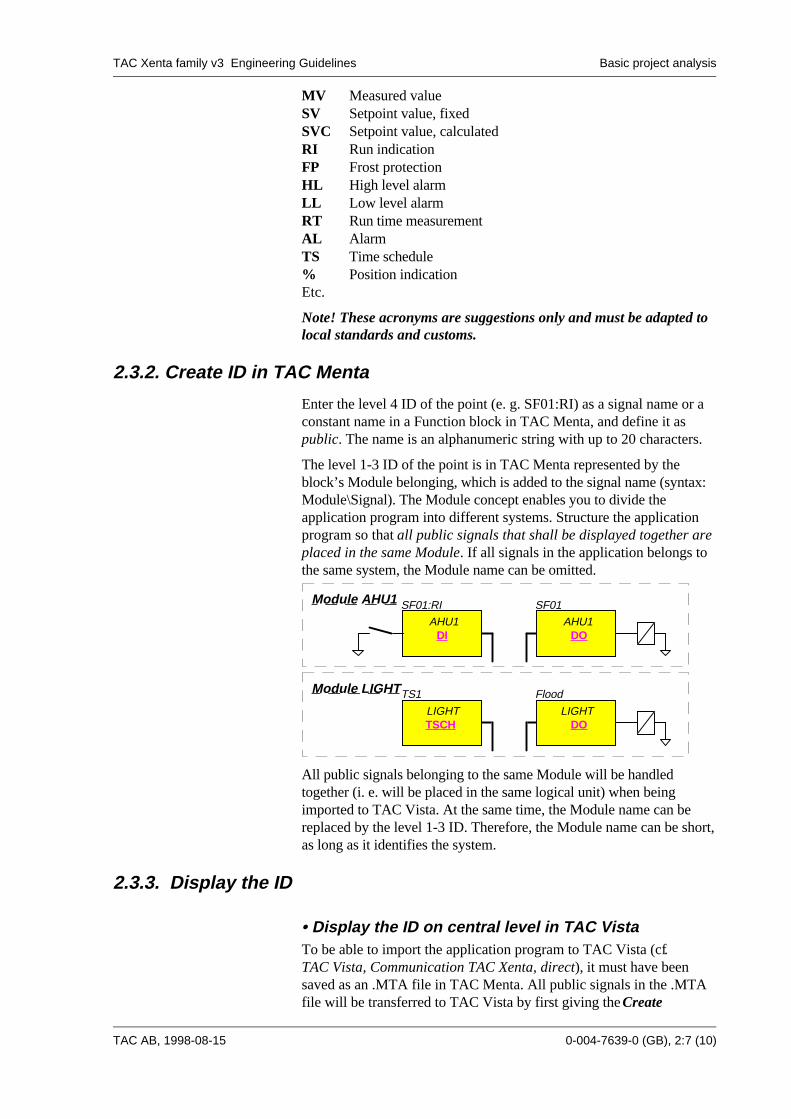
Enter the level 4 ID of the point (e. g. SF01:RI) as a signal name or aconstant name in a Function block in TAC Menta, and define it aspublic. The name is an alphanumeric string with up to 20 characters.
The level 1-3 ID of the point is in TAC Menta represented by theblock’s Module belonging, which is added to the signal name (syntax:Module\Signal). The Module concept enables you to divide theapplication program into different systems. Structure the applicationprogram so that all public signals that shall be displayed together areplaced in the same Module. If all signals in the application belongs tothe same system, the Module name can be omitted.
DODI
SF01:RI SF01Module AHU1
DOTSCH
TS1 FloodModule LIGHT
AHU1 AHU1
LIGHT LIGHT
All public signals belonging to the same Module will be handledtogether (i. e. will be placed in the same logical unit) when beingimported to TAC Vista. At the same time, the Module name can bereplaced by the level 1-3 ID. Therefore, the Module name can be short,as long as it identifies the system.
2.3.3. Display the ID
• Display the ID on central level in TAC VistaTo be able to import the application program to TAC Vista (cf.TAC Vista, Communication TAC Xenta, direct), it must have beensaved as an .MTA file in TAC Menta. All public signals in the .MTAfile will be transferred to TAC Vista by first giving the Create

TAC Xenta family v3 Engineering Guidelines Basic project analysis
0-004-7639-0 (GB), 2:8 (10) TAC AB, 1998-08-15
TAC Xenta description file command in the Database generator, andthen importing the created description file. The three upper ID levelswill be created at the same time, just by defining the logical unitcorresponding to the Module. Thus, each Module name can be changedto a new logical unit name in TAC Vista.
Database generator - Create TAC Xenta description file
TypeTAC Xenta 300
Process unit:Name-012-RPU01Current unit:
Current object ID:
Current object type:Physical connection:
Objects Units
012-AHU-AHU01
SF01:RI
012-RPU01 AHU01.SF01Digital input
SF01
SF01
TAC Vista presentation:TAC Vista - Object selection
2
1
1
2
3
Select application program (the.MTA file).
Enter logical unit (ID level 1-3) for the marked
Select TAC Xenta unit.
Module. All public signals in the marked Module
Application program:
Modules
Program fileC:\PROJECT\012\RPU01.MTA
SignalsSF01
LIGHTLOCK
AHU01SF01:RI
Logical unit012-AHU-AHU01
Description fileC:\PROJECT\012\RPU01.DES
are created as TA Vista objects in this unit.
3
Selected node:
Note:
- All points in a Module are automatically placed under the samelogical unit in TAC Vista.
- All object names are presented with capital letters in TAC Vista, nomatter how they are defined in TAC Menta.
• Display the ID on local level in the TAC Xenta OP
The user would appreciate if the ID hierarchy in the OP was exactlythe same as in TAC Vista. Unfortunately, this is normally hard to do,depending on that the OP displays the physical view of the network:The TAC Xenta groups, and the TAC Xenta units within each group.If, for example, a TAC Xenta unit holds more than one logical Module,you cannot display a Module without first selecting TAC Xenta unit.Therefore, it is better to consequently let the OP display the physicalID (Cf. Section 2.3.4) down to the level where the OP menu tree of theTAC Xenta unit is displayed:
R02 TEMPERATURESTS01_MV: 18.7°C TS01_SP: 19.0°COutdoor: -10.3°C
R02 012_AHU_AHU02 INFORMATION OP. STATUS TEMPERATURES AI
TS01_MVAINL
M0-B1
PVR
TS01_SP
InitValue19
TAC Menta FBD:
AHU02
AHU02
The first OP row can be used for presentation of the system(s)(corresponding to ID level 1-3) being present in this specificTAC Xenta unit. Use the Name field in the Program specification of
TAC Xenta family v3 Engineering Guidelines Basic project analysis
TAC AB, 1998-08-15 0-004-7639-0 (GB), 2:9 (10)
TAC Menta to enter this. The name field allows up to 20 characters,but since the Abbreviation is presented in the same OP row, amaximum of 15 characters can be used.
Divide the OP menu tree in different text displays for the differentsystems (Modules). The actual layout of the displays are created in theOP configuration tool, cf. section 3.2.3.
Note that if 15-20 characters are used in a signal name, then you mustuse two rows in the OP to show the point; one row for the name andone for the value. If you want to show both name and value in the samerow the name must be limited to 10-12 characters.
2.3.4. Physical ID
• Structure
The physical ID is used to identify the physical components of thecontrol system, i. e. the LonWorks network and its TAC Xenta units.Use three levels, where level 1 is the building or part of the building(the LonWorks network), level 2 is the cabinet (TAC Xenta group) andlevel 3 the TAC Xenta unit.
• Physical ID in the TAC Xenta OP
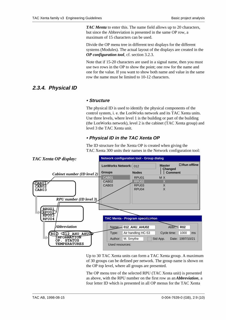
The ID structure for the Xenta OP is created when giving theTAC Xenta 300 units their names in the Network configuration tool:
RPU01RPU02 RPU03RPU04
R02 012_AHU_AHU02 INFORMATION OP. STATUS TEMPERATURES
RPU number (ID level 3)
CAB01 CAB02CAB03
Cabinet number (ID level 2)
Abbreviation
RPU01 M X
Groups
LonWorks Network: 012
CAB01
RPU04 X
Nodes
Master
CommentChanged
Run offline
RPU02 XRPU03 X
CAB02CAB03
Type:
TAC Menta - Program specification
Abbr:
Air handling HC-53
R02
Used resources:
Author: M. Smythe Date: 1997/10/21
Name: 012_AHU_AHU02
Std App.
Cycle time: 1000 ms
Network configuration tool - Group dialogTAC Xenta OP display:
Up to 30 TAC Xenta units can form a TAC Xenta group. A maximumof 30 groups can be defined per network. The group name is shown onthe OP top level, where all groups are presented.
The OP menu tree of the selected RPU (TAC Xenta unit) is presentedas above, with the RPU number on the first row as an Abbreviation, afour letter ID which is presented in all OP menus for the TAC Xenta

TAC Xenta family v3 Engineering Guidelines Basic project analysis
0-004-7639-0 (GB), 2:10 (10) TAC AB, 1998-08-15
unit. The full ID may have to be shortened when used as abbreviation.The abbreviation is entered in the Abbr. field in the Programspecification of TAC Menta.
• Physical ID in TAC Vista
The physical structure of the network is converted from the Networkdatabase into TAC Vista, and will then be displayed in the Statusmenu. To convert (cf. TAC Vista, Communication TAC Xenta, direct),use the Create description file command in the Networkconfiguration tool, and then import the created description file via theTAC Vista Database generator.
RPU01 M X
Groups
LonWorks Network: 012
CAB01
RPU04 X
Nodes
Master
CommentChanged
Run offline
RPU02 XRPU03 X
CAB02CAB03
Network configuration tool - Group dialog
HOSPITALPC_12
012CAB01
RPU01RPU02RPU03RPU04
TAC Vista - Status
TAC Vista Presentation:

TAC Xenta family v3 Engineering Guidelines Programming
TAC AB, 1998-08-15 0-004-7639-0 (GB), 3:1 (14)
3. Programming
3.1. Preparations
3.1.1. Environment and Tools
The work shall be organised in a PC with Windows environment.
If more than one person does programming, the standards used and thestructure of the programs are the same. If a network and a server isused, there must be one person responsible so that the organising of thehard disk and back ups etc. are carried out on regular basis.
Recommended computer configuration:
Computer: Intel� Pentium processor, at least 90 MHzMemory: > 16 MbytesHard disk: at least 50 Mbytes freeDisk drive: 3½"Display: 17" or largerGraphic: VGA
Each PC should contain the following programs:
- Windows95™- A good editor, like Microsoft® Word™- TAC Menta- TAC Vista
It is important that tests of the program can be carried out beforedelivery to the customer or the on-site commissioning. A basic testsystem could consist of:
- A TAC Xenta unit (301/302)- A TAC Xenta OP- A "Simulating box"
TAC Xenta family v3 Engineering Guidelines Programming
0-004-7639-0 (GB), 3:2 (14) TAC AB, 1998-08-15
3.1.2. Program licenses
Both TAC Vista and TAC Menta uses a hardware key connected to thePC printer port to lock/unlock (via password) program modules.Therefore, it is always important to, in advance, check the programlicense of the PC (Both at the customer and at the office) you will beworking with, or always to use your own hardware key. If bothTAC Vista and TAC Menta are installed on the PC, just one (acommon) hardware key shall be used.
• TAC Vista
TAC Vista consists of a basic module with functions for dailyoperation of the plant. Depending on the customer's requirements thereare optional program modules such as Colours graphics editor,Reports and presentations etc. which can be individuallylocked/unlocked. Note: Communication with TAC Xenta is such anoptional module.
• TAC Menta
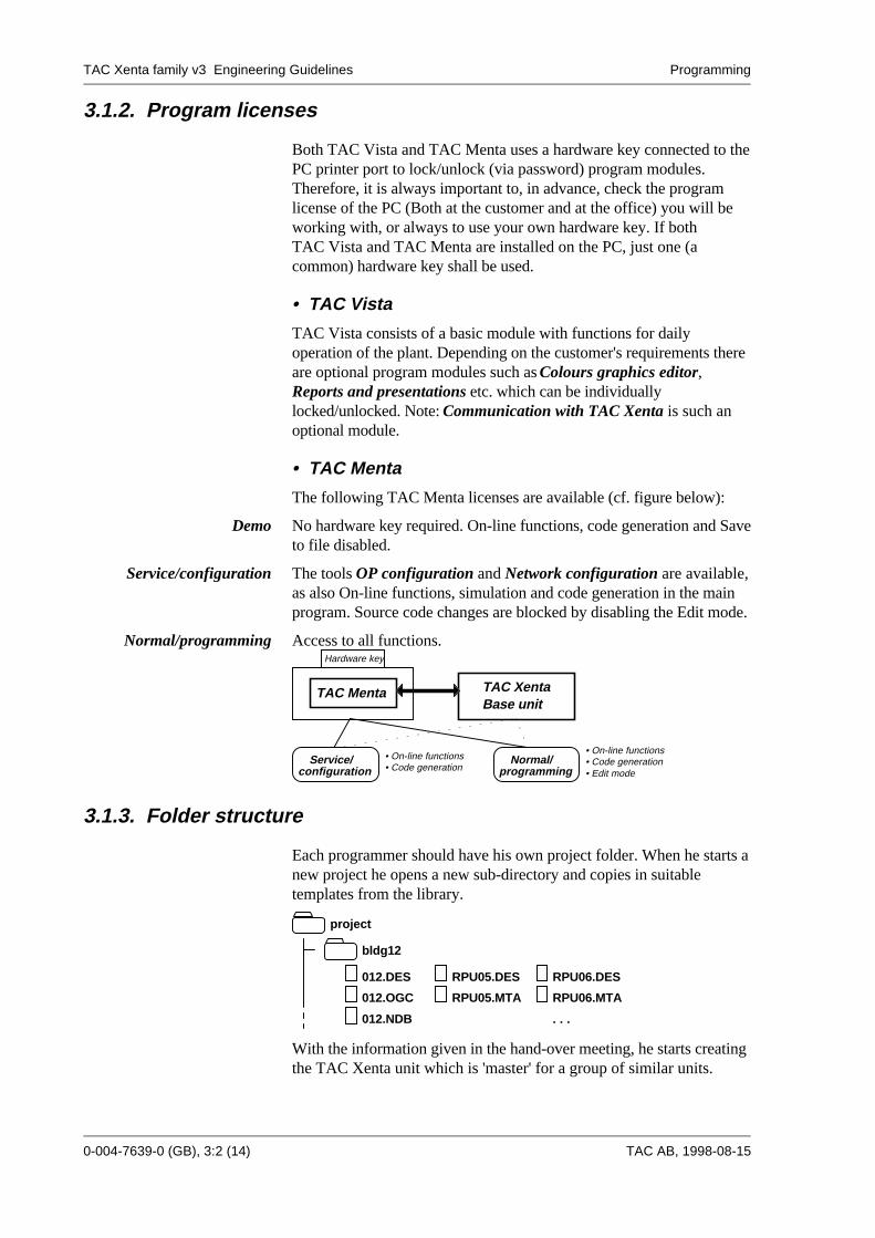
The following TAC Menta licenses are available (cf. figure below):
Demo No hardware key required. On-line functions, code generation and Saveto file disabled.
Service/configuration The tools OP configuration and Network configuration are available,as also On-line functions, simulation and code generation in the mainprogram. Source code changes are blocked by disabling the Edit mode.
Normal/programming Access to all functions. Hardware key
TAC Menta TAC Xenta
• On-line functions• Code generation
• On-line functions• Code generation• Edit modeconfiguration
Service/programming
Normal/
Base unit
3.1.3. Folder structure
Each programmer should have his own project folder. When he starts anew project he opens a new sub-directory and copies in suitabletemplates from the library.
bldg12
012.NDB
012.OGC
012.DES
project
RPU05.DES
RPU05.MTA
RPU06.DES
RPU06.MTA
. . .
With the information given in the hand-over meeting, he starts creatingthe TAC Xenta unit which is 'master' for a group of similar units.
TAC Xenta family v3 Engineering Guidelines Programming
TAC AB, 1998-08-15 0-004-7639-0 (GB), 3:3 (14)
When the 'master' TAC Xenta unit is completed and tested, makecopies for the other TAC Xenta unit's in the group, and complete theprogramming of each TAC Xenta unit.
Then start with the next group of systems using the same method.
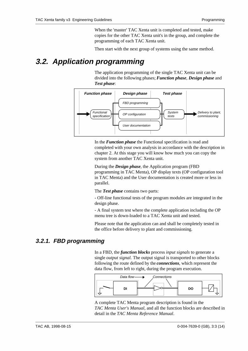
3.2. Application programmingThe application programming of the single TAC Xenta unit can bedivided into the following phases; Function phase, Design phase andTest phase:
Functionalspecification OP configuration
FBD programming
User documentation
Function phase Design phase Test phase
Systemtests
Delivery to plant,commissioning
In the Function phase the Functional specification is read andcompleted with your own analysis in accordance with the description inchapter 2. At this stage you will know how much you can copy thesystem from another TAC Xenta unit.
During the Design phase, the Application program (FBDprogramming in TAC Menta), OP display texts (OP configuration toolin TAC Menta) and the User documentation is created more or less inparallel.
The Test phase contains two parts:
- Off-line functional tests of the program modules are integrated in thedesign phase.
- A final system test where the complete application including the OPmenu tree is down-loaded to a TAC Xenta unit and tested.
Please note that the application can and shall be completely tested inthe office before delivery to plant and commissioning.
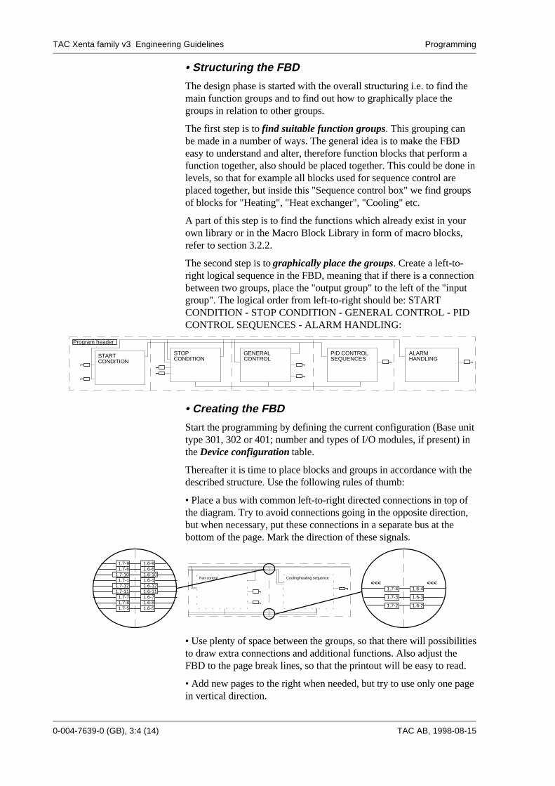
3.2.1. FBD programming
In a FBD, the function blocks process input signals to generate asingle output signal. The output signal is transported to other blocksfollowing the route defined by the connections, which represent thedata flow, from left to right, during the program execution.
DODI
Data flow Connections
A complete TAC Menta program description is found in theTAC Menta User's Manual, and all the function blocks are described indetail in the TAC Menta Reference Manual.
TAC Xenta family v3 Engineering Guidelines Programming
0-004-7639-0 (GB), 3:4 (14) TAC AB, 1998-08-15
• Structuring the FBD
The design phase is started with the overall structuring i.e. to find themain function groups and to find out how to graphically place thegroups in relation to other groups.
The first step is to find suitable function groups. This grouping canbe made in a number of ways. The general idea is to make the FBDeasy to understand and alter, therefore function blocks that perform afunction together, also should be placed together. This could be done inlevels, so that for example all blocks used for sequence control areplaced together, but inside this "Sequence control box" we find groupsof blocks for "Heating", "Heat exchanger", "Cooling" etc.
A part of this step is to find the functions which already exist in yourown library or in the Macro Block Library in form of macro blocks,refer to section 3.2.2.
The second step is to graphically place the groups. Create a left-to-right logical sequence in the FBD, meaning that if there is a connectionbetween two groups, place the "output group" to the left of the "inputgroup". The logical order from left-to-right should be: STARTCONDITION - STOP CONDITION - GENERAL CONTROL - PIDCONTROL SEQUENCES - ALARM HANDLING:
Program header
START STOP GENERAL PID CONTROL
CONDITION CONDITION CONTROL SEQUENCESALARMHANDLING
• Creating the FBD
Start the programming by defining the current configuration (Base unittype 301, 302 or 401; number and types of I/O modules, if present) inthe Device configuration table.
Thereafter it is time to place blocks and groups in accordance with thedescribed structure. Use the following rules of thumb:
• Place a bus with common left-to-right directed connections in top ofthe diagram. Try to avoid connections going in the opposite direction,but when necessary, put these connections in a separate bus at thebottom of the page. Mark the direction of these signals.
1.7-91.7-6
1.7-101.7-1
1.7-121.7-11
1.7-71.7-81.7-5
1.6-91.6-61.6-101.6-11.6-121.6-111.6-71.6-81.6-5
1.7-4
1.7-3
1.7-2
1.6-4
1.6-3
1.6-2
<<< <<<Fan control Cooling/heating sequence
• Use plenty of space between the groups, so that there will possibilitiesto draw extra connections and additional functions. Also adjust theFBD to the page break lines, so that the printout will be easy to read.
• Add new pages to the right when needed, but try to use only one pagein vertical direction.
TAC Xenta family v3 Engineering Guidelines Programming
TAC AB, 1998-08-15 0-004-7639-0 (GB), 3:5 (14)
• Try to structure every page so that the physical input blocks areplaced in a row to the left, and the physical output blocks are placed ina row to the right.
• Re-use tested macro blocks from the Macro Block Library or fromyour own library as much as possible.
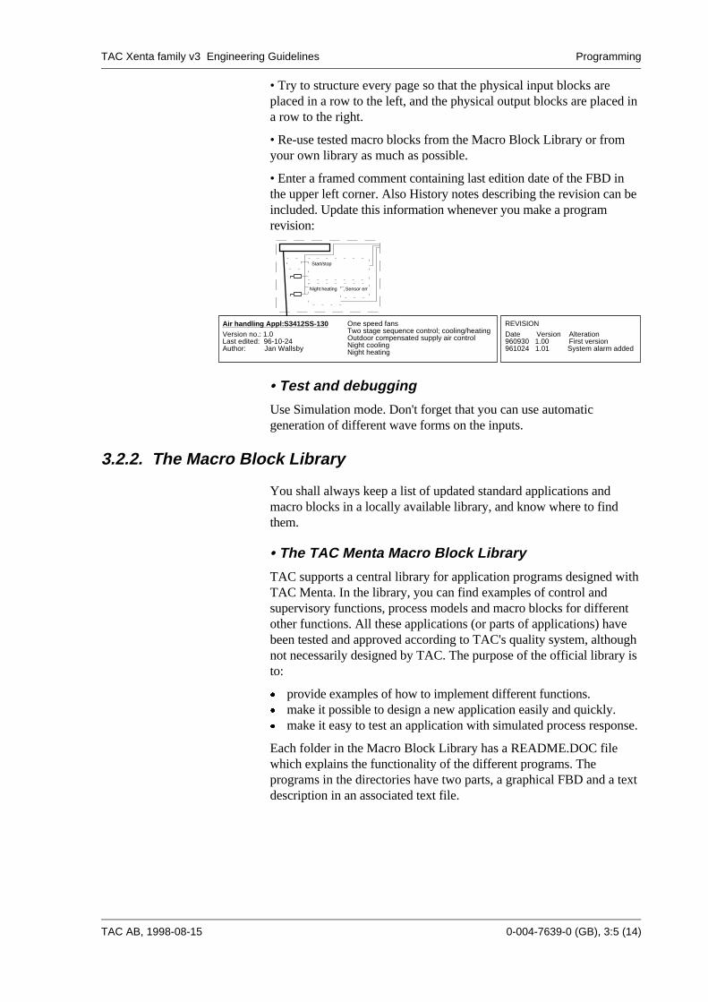
• Enter a framed comment containing last edition date of the FBD inthe upper left corner. Also History notes describing the revision can beincluded. Update this information whenever you make a programrevision:
Air handling Appl:S3412SS-130
Author: Jan Wallsby
Version no.: 1.0Last edited: 96-10-24
One speed fansTwo stage sequence control; cooling/heatingOutdoor compensated supply air controlNight coolingNight heating
REVISION
Date Version Alteration 960930 1.00 First version 961024 1.01 System alarm added
Start/stop
Night heating Sensor err
• Test and debugging
Use Simulation mode. Don't forget that you can use automaticgeneration of different wave forms on the inputs.
3.2.2. The Macro Block Library
You shall always keep a list of updated standard applications andmacro blocks in a locally available library, and know where to findthem.
• The TAC Menta Macro Block Library
TAC supports a central library for application programs designed withTAC Menta. In the library, you can find examples of control andsupervisory functions, process models and macro blocks for differentother functions. All these applications (or parts of applications) havebeen tested and approved according to TAC's quality system, althoughnot necessarily designed by TAC. The purpose of the official library isto:
x provide examples of how to implement different functions.x make it possible to design a new application easily and quickly.x make it easy to test an application with simulated process response.
Each folder in the Macro Block Library has a README.DOC filewhich explains the functionality of the different programs. Theprograms in the directories have two parts, a graphical FBD and a textdescription in an associated text file.
TAC Xenta family v3 Engineering Guidelines Programming
0-004-7639-0 (GB), 3:6 (14) TAC AB, 1998-08-15
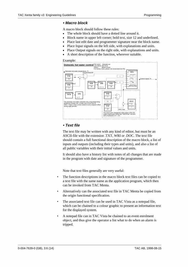
• Macro block
A macro block should follow these rules:x The whole block should have a dotted line around it.x Block name in upper left corner; bold text, size 12 and underlined.x Place last edit date and programmer signature near the block name.x Place Input signals on the left side, with explanations and units.x Place Output signals on the right side, with explanations and units.x A short description of the function, wherever suitable.
Example:
TSCHHotWaterTime
1
File name: hotwater.autLast edition: 96-10-01Author: Mikael KrantzFor history notes, please see associated text file.
Control signal, %(R l)
Domestic hot water temperature, °C(R l)
The domestic hot water controller has a load dependingdeadzone change over, to take care of low flow atHWC. There is also a time control to set a setpoint offsetduring night periods.
Domestic hot water control
The dead zone changeover takes place when theoutput signal goes below the "HWCFlow" set limitwith a hysteresis of +- 1%.
PVRHWCFlow
InitValue10
�
0.5
PVRHWCDzone
InitValue5
HWC flow
HYSTActivate
-1Deactivate
1
1
0
PVRHotWaterSetback
InitValue0
�
ActualHotWaterSP
1
0
XPB
A<0
A
0PVR
HotWaterITime
InitValue30
XPRHWGain
100/A
APVR
HotWaterPBand
InitValue50
PVRHotWaterSV
InitValue50
PIDAHotWaterControl
ControlInt1
UMin0
UMax100
StrokeTimeHWTravelTime
MV
SP
Mod
G
Ti
Td
DZ
TSg
• Text file
The text file may be written with any kind of editor, but must be anASCII-file with the extension .TXT, WRI or .DOC. The text fileshould contain a full functional description of the macro block, a list ofinputs and outputs (including their types and units), and also a list ofall public variables with their initial values and units.
It should also have a history list with notes of all changes that are madein the program with date and signature of the programmer.
Note that text files generally are very useful:
• The function descriptions in the macro block text files can be copied toa text file with the same name as the application program, which thencan be invoked from TAC Menta.
• Alternatively can the associated text file in TAC Menta be copied fromthe origin functional specification.
• The associated text file can be used in TAC Vista as a notepad file,which can be chained to a colour graphic to present an information textfor the displayed system.
• A notepad file can in TAC Vista be chained to an event enrolmentobject, and thus give the operator a list what to do when an alarm istripped.
TAC Xenta family v3 Engineering Guidelines Programming
TAC AB, 1998-08-15 0-004-7639-0 (GB), 3:7 (14)
3.2.3. OP configuration
The TAC Xenta OP is used to give the operator access to plant status,alarms and parameters. The information is presented as a number of4*20 character displays. The displays are structured as a menu tree.
This chapter contains some hints on how to structure the menu tree.
• Automatic generation of the menu tree
The menu tree will automatically be generated at everygenerate/download command in TAC Menta, if Preferences -Automatic generation of menu tree is selected in simulation mode. Thegenerated menu tree will have a fix structure with all public signals andconstants divided into separate displays for digital signals, analogsignals and time schedules. Also, different modules will be presentedseparately. This is the quickest way to create a menu tree, and shouldbe used if there is no specific demand for a menu tree structure. Thedisadvantage is that you in this way may get very long andunstructured signal lists.
• Structuring the menu tree manually
You can manually configure the OP menu tree and the text displays intwo different ways, both described in the TAC Menta User's Manual:1) Graphically in the OP configuration tool, or2) In a text file (the OP description file), which is imported to the OPconfiguration tool.
In both cases, the menu tree structuring mainly consists of two parts:
• The Logical structuring, meaning to group items which are logicallyconnected together e.g. all fan parameters.
• The Operator dependent structuring, meaning to divide the items intogroups with different interest for different operators.
The first rule of thumb is to place items of interest for the dailyoperator at the top of the menu tree. The daily operator, having a lowaccess level, should mainly be able to read the plant status, read andacknowledge alarms and alter a few values, typically the setpoints.
Settings which are seldom altered, and then by an authorised operatorwith medium or high access level, are placed further down in the menutree.

TAC Xenta family v3 Engineering Guidelines Programming
0-004-7639-0 (GB), 3:8 (14) TAC AB, 1998-08-15
• Standard for OP menus
The basic menu tree structure should be like this:
ACCESS CODE
PARAMETERS
DATE & TIME
DAYLIGHT SAVING
CHANGE CODE
NAME
OP STATUS
ALARMS
WEEK CHARTS
HOLIDAYS
INFORMATION
VALUES
TEMPERATURES
DEGREE DAYS
TEMPERATURES
SETPOINTS
CURVES
TIME SCHEDULES
START
- Application type and version
- Measured values and Setpoints (RO)one display per value
- Last month's degree daysone display per value
- (R/W)
- Auto/Manual switch and Restartof the AHU
- Control parameters, system parameterssuch as delays etc.
Lowaccess
Mediumaccess(level 1)
Highaccess(level 2)
Note that there is no need for a specific manual control menu. The I/Opoints can be manually forced in the status menu, if the user logs inwith the high level password.
3.2.4. User documentation
The printout function of TAC Menta contains a number ofpossibilities, but you don't have to use all since some information areincluded in more than one list.
The most important TAC Menta printouts in a TAC Vista project areI/O list, public signals and FBD, together with colour graphics anddescription files from TAC Vista, and of course the functionalspecification.
In a stand alone project, you should document I/O-list, public signals,time schedules, alarm texts, FBD and OP menu tree.
TAC Xenta family v3 Engineering Guidelines Programming
TAC AB, 1998-08-15 0-004-7639-0 (GB), 3:9 (14)
3.3. TAC Vista
3.3.1. General
A TAC Vista system is built up of objects, defined in a database. Thedatabase must exist before you can convert control programs, or useaddress symbols and values in colour graphics etc.
TAC Vista may use absolute or relative addressing. Relativeaddressing means that you - for example in a colour graphic (BLDGA-FLOOR4-PICT) - refer to the last level of the object IDs. Absoluteaddress: BLDGA-FLOOR4-T1, relative address: T1. By means ofrelative addressing the colour graphics can easily be moved to anotherlocation in the logical tree structure where there also is a point namedT1.
3.3.2. Database generator
To program the objects and their attributes in an efficient way you usethe Database generator, cf. the TAC Vista Database generator manual.
In the Database generator you can perform editing and syntax check ofdescription files. You can convert RPU documents and TAC Xentaunits and you can export and update data to the description file. Youcan also import data to the database.
There are template files with predefined texts and attributes fordifferent types of process units. Try to create a number of descriptionfiles, each for a specific process unit or part of the project. The data inthe different description files can be imported to the database at thesame time via a batch file.
3.3.3. Colour graphics
The colour graphic editor offers the option to document which pointsthe graphic contains in a list that is easy to survey.
In the editor you may also simulate the dynamic functions in the colourgraphic.
When creating colour graphics for the plant, it is a good idea to createa tree structure with an overview graphic "at the top", from which youcan reach lower levels of the plant, and to which you can return. Theoverview graphic may be in the form of an imported photographicimage or a plant drawing, over which transparent link areas can beplaced. These link areas fetch the colour graphics for the relevant partof the plant. For further details, see the section on link areas below.
Plan the tree structure for graphics in a way that makes it easy for theuser, and facilitates adding new graphics when the plant is changed.
Be consistent in the use of colours and line types. Createdocumentation on the selection of colours and line types in the systemby keeping a record. See the standard on the following page.
TAC Xenta family v3 Engineering Guidelines Programming
0-004-7639-0 (GB), 3:10 (14) TAC AB, 1998-08-15
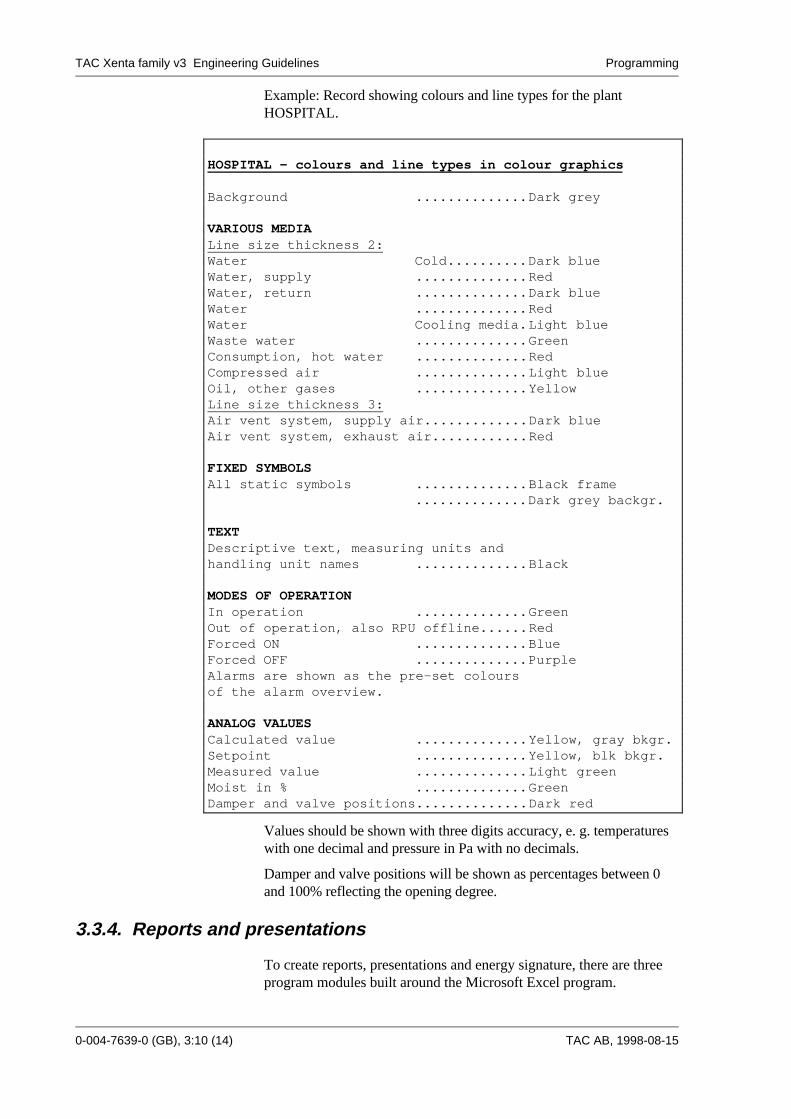
Example: Record showing colours and line types for the plantHOSPITAL.
HOSPITAL - colours and line types in colour graphics
Background ..............Dark grey
VARIOUS MEDIALine size thickness 2:Water Cold..........Dark blueWater, supply ..............RedWater, return ..............Dark blueWater ..............RedWater Cooling media.Light blueWaste water ..............GreenConsumption, hot water ..............RedCompressed air ..............Light blueOil, other gases ..............YellowLine size thickness 3:Air vent system, supply air.............Dark blueAir vent system, exhaust air............Red
FIXED SYMBOLSAll static symbols ..............Black frame
..............Dark grey backgr.
TEXTDescriptive text, measuring units andhandling unit names ..............Black
MODES OF OPERATIONIn operation ..............GreenOut of operation, also RPU offline......RedForced ON ..............BlueForced OFF ..............PurpleAlarms are shown as the pre-set coloursof the alarm overview.
ANALOG VALUESCalculated value ..............Yellow, gray bkgr.Setpoint ..............Yellow, blk bkgr.Measured value ..............Light greenMoist in % ..............GreenDamper and valve positions..............Dark red
Values should be shown with three digits accuracy, e. g. temperatureswith one decimal and pressure in Pa with no decimals.
Damper and valve positions will be shown as percentages between 0and 100% reflecting the opening degree.
3.3.4. Reports and presentations
To create reports, presentations and energy signature, there are threeprogram modules built around the Microsoft Excel program.
TAC Xenta family v3 Engineering Guidelines Programming
TAC AB, 1998-08-15 0-004-7639-0 (GB), 3:11 (14)
3.3.5. General working method
The following general working method shall normally be used whencreating a TAC Vista system, no matter if it is connected toTAC ZONE II units or TAC Xenta units:
1 - Install the TAC Vista software on the PC.
2 - Do the point identification/allocation in accordance with chapter 2.
3 - Create a system description file (Use either SYSTEM.DEM orLONWORKS.DEM as a template) describing all central functions andunits such as communication ports, alarm processing objects, alarmreceivers, trend logging objects etc. and import it to the database bymeans of the Database generator.
4 - Create a description file for each RPU in the system. Edit thedescription file and import it to the database by means of the Databasegenerator.
5 - Draw, copy and/or edit Colour graphics, Reports and Note files.Save them as .OGC, .XLS and .TXT files respectively.
6 - Add Colour graphic and Report objects to the RPU description filesand import again. Remember to put the graphic in the same logical unitas the points it is displaying.
7 - Make a function check, cf. chapter 4.
8 - Update all description files.
3.3.6. Creating a database for TAC Xenta units
Use the working method below when creating a TAC Vista databasefor TAC Xenta units, cf. TAC Vista Communication TAC Xenta,direct.
From version 3.1, it is possible to download the application program toTAC Xenta either via a direct connection to TAC Menta, or via TACVista and the LonWorks network. Below, download via the network isshown, but the application might as well be downloaded by using TACMenta when directly connected under stage 2.
1 - Create the application program in TAC Menta (cf. section 3.2), andsave all files as an .MTA file in the folder for the TAC Xenta unit inquestion. Repeat these actions for all TAC Xenta units.
2 - Create the LonWorks network, the Groups and the Nodes (the TACXenta units) in the Network configuration tool. Configure all the TACXenta units including their I/O modules. Save the network database asan .NDB file. Thereafter, download the network configuration to theTAC Xenta units, one by one, via the serial port.
3 - Create a system description file (use LONWORKS.DEM) andimport it to TAC Vista. Note especially the communication port for theLTA unit and its address, e. g. PCCLON1.

TAC Xenta family v3 Engineering Guidelines Programming
0-004-7639-0 (GB), 3:12 (14) TAC AB, 1998-08-15
4 - Create a Network configuration description file (reads the .NDBfile) and import it to TAC Vista. The file should have the same name asthe network, e. g. BLDG012.DES.
5 - Set TAC Vista in on-line mode. Open the LonWorks networkobject and check the domain table and the address table. Enter the TACVista Status menu and check that the TAC Xenta units are on-line.
6 - Convert the application program for a TAC Xenta to a descriptionfile via the Create TAC Xenta description file command in theDatabase generator's Tools menu. Enter the requested logical unit foreach module in the application program. Place the description file in thesame folder as the .MTA file.
Edit the description file, if needed. Alarm object references etc. mayhave to be added. Note that these alterations in the description file aredeleted if you convert the application program a second time.Therefore, always note your alterations!
Import the description file.
Repeat point 6 for every TAC Xenta unit in the system.
The system definition phase can be speeded up, if the description filesare run via a batch file defined in the Database generator. Place thebatch file and the description files in the same folder.
7 - Download the application program by selecting Status in the menuShow and mark the unit(s) to be downloaded. Then select Download -application and parameters in the pop-up menu (right mouse button).
Check that you have contact with the TAC Xenta points.
3.3.7. System documentation
In TAC Vista it is easy and fast to document the system by means ofpredefined lists:
- System configuration- Process units- Objects- Inputs/Outputs- Check list- Forced variables
3.3.8. Backup
Note that a new backup function has been implemented in TAC Vistav3.1, to backup the TAC Vista database. Both a complete and anincremental backup is included. It is simple to perform backup of alloperator units in a TAC Vista network and storing the backups on acommon network server.
TAC Xenta family v3 Engineering Guidelines Programming
TAC AB, 1998-08-15 0-004-7639-0 (GB), 3:13 (14)
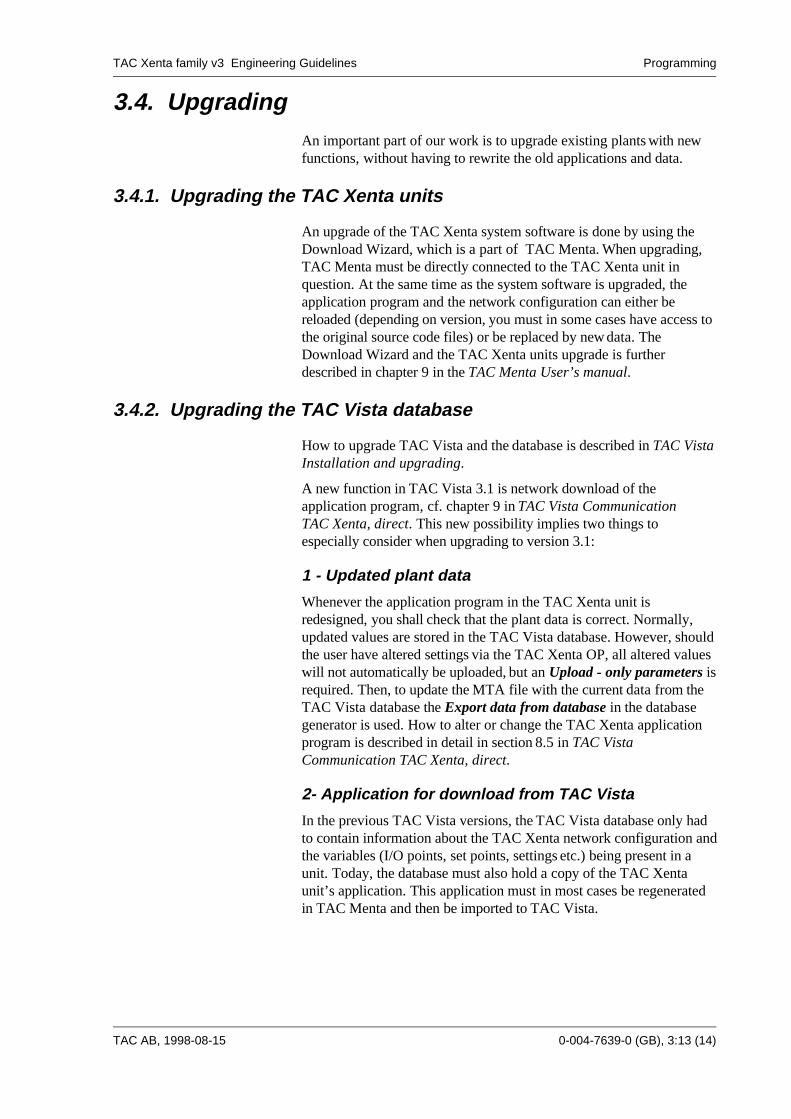
3.4. UpgradingAn important part of our work is to upgrade existing plants with newfunctions, without having to rewrite the old applications and data.
3.4.1. Upgrading the TAC Xenta units
An upgrade of the TAC Xenta system software is done by using theDownload Wizard, which is a part of TAC Menta. When upgrading,TAC Menta must be directly connected to the TAC Xenta unit inquestion. At the same time as the system software is upgraded, theapplication program and the network configuration can either bereloaded (depending on version, you must in some cases have access tothe original source code files) or be replaced by new data. TheDownload Wizard and the TAC Xenta units upgrade is furtherdescribed in chapter 9 in the TAC Menta User’s manual.
3.4.2. Upgrading the TAC Vista database
How to upgrade TAC Vista and the database is described in TAC VistaInstallation and upgrading.
A new function in TAC Vista 3.1 is network download of theapplication program, cf. chapter 9 in TAC Vista CommunicationTAC Xenta, direct. This new possibility implies two things toespecially consider when upgrading to version 3.1:
1 - Updated plant data
Whenever the application program in the TAC Xenta unit isredesigned, you shall check that the plant data is correct. Normally,updated values are stored in the TAC Vista database. However, shouldthe user have altered settings via the TAC Xenta OP, all altered valueswill not automatically be uploaded, but an Upload - only parameters isrequired. Then, to update the MTA file with the current data from theTAC Vista database the Export data from database in the databasegenerator is used. How to alter or change the TAC Xenta applicationprogram is described in detail in section 8.5 in TAC VistaCommunication TAC Xenta, direct.
2- Application for download from TAC Vista
In the previous TAC Vista versions, the TAC Vista database only hadto contain information about the TAC Xenta network configuration andthe variables (I/O points, set points, settings etc.) being present in aunit. Today, the database must also hold a copy of the TAC Xentaunit’s application. This application must in most cases be regeneratedin TAC Menta and then be imported to TAC Vista.
TAC Xenta family v3 Engineering Guidelines Programming
0-004-7639-0 (GB), 3:14 (14) TAC AB, 1998-08-15
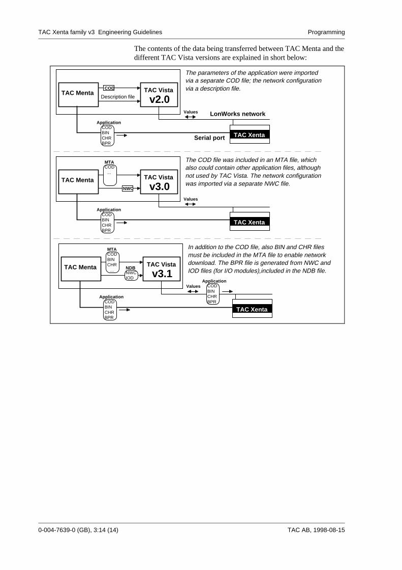
The contents of the data being transferred between TAC Menta and thedifferent TAC Vista versions are explained in short below:
TAC Xenta
TAC Menta TAC Vista
v3.1
CODBINCHR
...
MTA
CODBINCHR
Application
BPR
NWCIOD
NDB
CODBINCHR
Application
BPR
Values
TAC Xenta
TAC Menta TAC Vista
v3.0
COD...
MTA
CODBINCHR
Application
BPR
Values
NWC
TAC Xenta
TAC Menta TAC Vista
v2.0
CODBINCHR
Application
BPR
Values
COD
LonWorks network
Serial port
Description file
The parameters of the application were imported via a separate COD file; the network configurationvia a description file.
The COD file was included in an MTA file, which also could contain other application files, although
was imported via a separate NWC file.not used by TAC Vista. The network configuration
In addition to the COD file, also BIN and CHR filesmust be included in the MTA file to enable network
IOD files (for I/O modules),included in the NDB file.download. The BPR file is generated from NWC and
TAC Xenta family v3 Engineering Guidelines Commissioning
TAC AB, 1998-08-15 0-004-7639-0 (GB), 4:1 (5)
4. CommissioningHow to commission the installation depends on its size and complexity.
A single standard TAC Xenta unit with or without I/O modules can becommissioned without any other tool than the OP, cf. TAC XentaHandbook, on the condition that the Service Menu is present in the OP.
When the TAC system is integrated with systems from other vendors, aco-operation between TAC Menta and an external tool is needed.Especially the network and all functions working via the network areaffected, cf. TAC Xenta Network Guide. Always first consult the Guidewhen dealing with network tasks such as cable types and lengths,traffic sectioning and the need of additional equipment (repeaters,routers, gateways etc.).
In all other situations, the only tool needed is TAC Menta.
4.1. Commissioning with TAC MentaCommissioning in the following steps:
1 - Initial checking (to avoid high voltage in to the electronics)
2 - Network configuration (Connecting the TAC Xenta units)
3 - I/O test
4 - Functional test (of the application program)
4.1.1. Initial checking
For each TAC Xenta unit and I/O module, the following must bechecked after the wires have been connected, but before the electronicspart is mounted on the terminal part.
• Turn on the power.
• Check that the supply voltage, 24 V AC or DC is connected to theproper terminals G and G0.
• Check that the voltage levels of the input and output terminals arereasonable.
• Check the voltage, both AC and DC, between G0 and all otherterminals. Repeat the procedure with G as the reference terminal.
TAC Xenta family v3 Engineering Guidelines Commissioning
4:2 (5), 0-004-7639-0 (GB) TAC AB, 1998-08-15
4.1.2. Network configuration
Before it can start to communicate, each TAC Xenta unit must beassigned a network address, i. e. a subnet/node address and a devicename. To do this a PC with TAC Menta is needed.
It is a good idea to, if possible, mount and configure the TAC Xentaunits one by one, instead of mounting all at the same time and thenconfiguring them. For each TAC Xenta unit do the following to set thenetwork addresses:
• Turn off the power and mount the electronics part on the terminal part.
Note! It is important that the electronics part has the same input/outputconfiguration as the terminal part.Also check that correct type of base unit is being used:- TAC Xenta 300 N communicates with other TAC Xenta base units.- TAC Xenta 300 NP also communicates with TAC Vista.
• Turn on the power again.
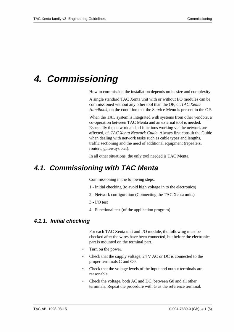
• Connect the PC to the TAC Xenta unit:
- Application download- Device configuration- Online simulation
TAC Xenta Base unit
TAC Menta:
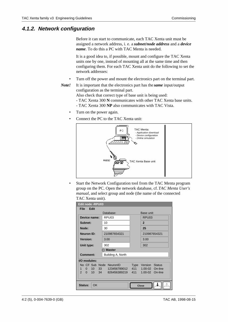
• Start the Network Configuration tool from the TAC Menta programgroup on the PC. Open the network database, cf. TAC Menta User'smanual, and select group and node (the name of the connectedTAC Xenta unit).
Edit node -RPU03
No CF Sub Node NeuronID Type Version Status1 0 10 33 123456789012 411 1.00-02 On-line2 0 10 34 826456389219 411 On-line
I/O modules:
Base unit:
Device name:
Subnet:
Node:
Version:
Neuron ID:
3.00
210987654321
Status: OK
1.00-02
Comment:
Master
File Edit
Close
10
RPU03
30
Building A, North
Database:
3.00
210987654321
2
RPU03
25
Unit type: 302 302
TAC Xenta family v3 Engineering Guidelines Commissioning
TAC AB, 1998-08-15 0-004-7639-0 (GB), 4:3 (5)
• Check that the configuration data to be downloaded are correct. It isvery important that all units are defined in the network database beforeyou start down-loading the data to any unit. Whenever you add a unitor alter its configuration, you must down-load the configuration data toall units in the group again! If you add a TAC Xenta group, you mustdown-load the configuration data to all units in the network!
Configure the TAC Xenta unit and its I/O modules. To identify an on-line I/O module, its service pin can be pressed. Note that theconfiguration data stored in the TAC Xenta unit will not be affected bya later download of the application program.
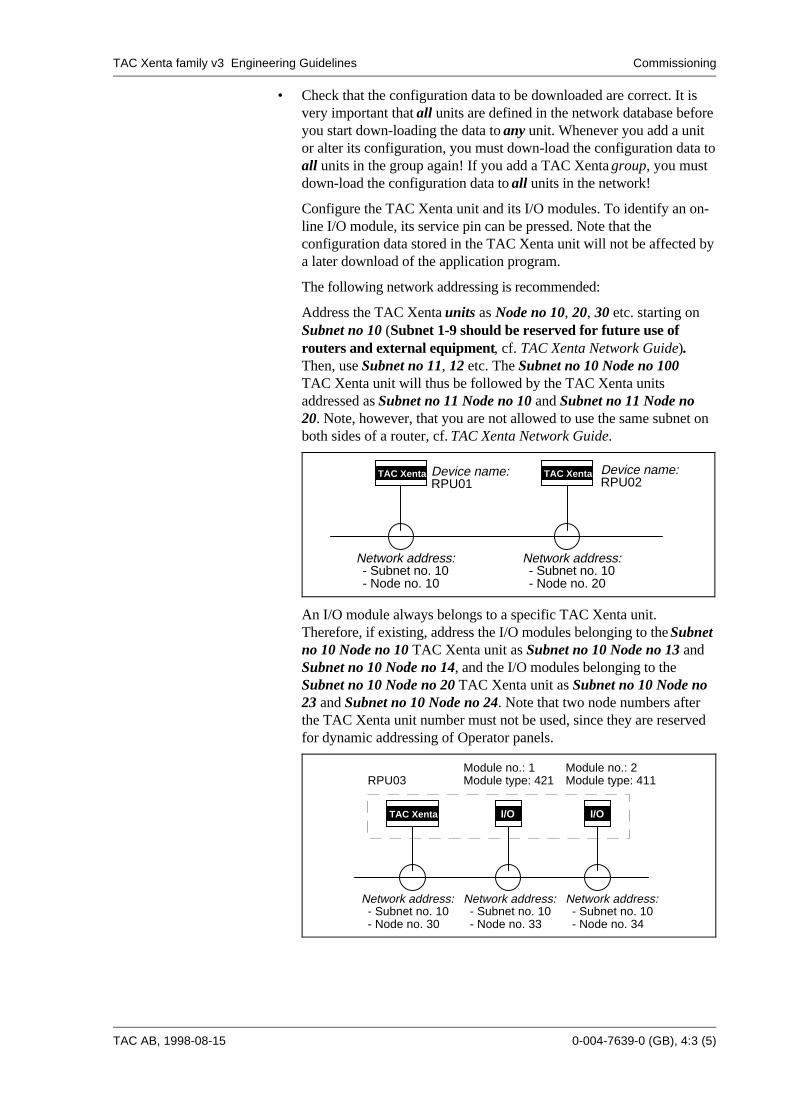
The following network addressing is recommended:
Address the TAC Xenta units as Node no 10, 20, 30 etc. starting onSubnet no 10 (Subnet 1-9 should be reserved for future use ofrouters and external equipment, cf. TAC Xenta Network Guide).Then, use Subnet no 11, 12 etc. The Subnet no 10 Node no 100TAC Xenta unit will thus be followed by the TAC Xenta unitsaddressed as Subnet no 11 Node no 10 and Subnet no 11 Node no20. Note, however, that you are not allowed to use the same subnet onboth sides of a router, cf. TAC Xenta Network Guide.
Device name:RPU01
Device name:RPU02
Network address:- Subnet no. 10- Node no. 10
Network address:- Subnet no. 10- Node no. 20
TAC Xenta TAC Xenta
An I/O module always belongs to a specific TAC Xenta unit.Therefore, if existing, address the I/O modules belonging to the Subnetno 10 Node no 10 TAC Xenta unit as Subnet no 10 Node no 13 andSubnet no 10 Node no 14, and the I/O modules belonging to theSubnet no 10 Node no 20 TAC Xenta unit as Subnet no 10 Node no23 and Subnet no 10 Node no 24. Note that two node numbers afterthe TAC Xenta unit number must not be used, since they are reservedfor dynamic addressing of Operator panels.
Network address:- Subnet no. 10- Node no. 30
Network address:- Subnet no. 10- Node no. 33
Network address:- Subnet no. 10- Node no. 34
Module no.: 1Module type: 421
Module no.: 2Module type: 411RPU03
TAC Xenta I/O I/O
TAC Xenta family v3 Engineering Guidelines Commissioning
4:4 (5), 0-004-7639-0 (GB) TAC AB, 1998-08-15
4.1.3. I/O test
The best way to test the external equipment connected to theTAC Xenta unit's inputs and outputs, is to down-load the applicationprogram, and then use the TAC Menta on-line functions to test the I/Opoints one by one. Thanks to the on-line trend-log one person canlocally open/close the inputs one by one, and then afterwards consultthe trend-log to see that they were activated in the correct order.Alternatively, you can by means of a special test application, whereeach input is connected to an alarm block, open/close the inputs one byone, and then consult the OP alarm list to see that the alarms weretripped in the correct order.
Note! It is important to first check that no danger may occur when setting theoutputs.
• Connect the PC to the TAC Xenta unit.
• Start TAC Menta and open the application program.
• Down-load the program, using the On-line button in TAC Menta'sSimulation mode.
• Check that the LED on the front starts to blink, indicating that theinternal program is running.
• Check the I/O points one by one. The current status/value of the I/Opoint is dynamically updated in the corresponding function block. EachI/O value can be forced by means of the Override button in the I/Oconfiguration table. If a faulty I/O binding (Incorrect terminalreference, input/output range etc.) should occur, this can be correctedvia the Bind button in the same table. Note, however, that theapplication program must be down-loaded again after altering thebinding information.
Note that the same application program can be down-loaded to anumber of TAC Xenta units. In this case, use the Programspecification to set the correct TAC Xenta unit name before down-loading each TAC Xenta unit:

TAC Xenta family v3 Engineering Guidelines Commissioning
TAC AB, 1998-08-15 0-004-7639-0 (GB), 4:5 (5)
Type:
OK
Program specification
Type Access Units
FanDelay
EFAlarmDelay
HeatSPHeatPband
EF
EF_Op
HeatITime
LowSuppLimitMV
Identifier
Abbr:
Air handling HC-53
R03
Used resources:Blocks: I/O signals:
DIs AIs DOs AOs3 2 4 1
53
Public signal table:
Author: M. Smythe Date: 1997/10/21
PAR RW seconds
PAI RW seconds
ANA RW °CANA RW °C
DIG RO
DIG RO
ANA RW minutes
ANA RW °CANA RW
Name: 012_AHU_003
Std App.
Cancel
Cycle time: 1000 ms
The entered Name and Abbreviation (max. 4 characters) willautomatically be generated and down-loaded to the TAC Xenta unit'sOP menu system, after pressing the On-line button.
4.1.4. Functional test
The application program should always be offline tested in theTAC Menta Simulation mode. At commissioning the following istested:
• Connect the TAC Xenta OP. Log in to the TAC Xenta units one byone.
• Select the Temp & Status menu (or corresponding) to check that allinputs have got reasonable values.
• Check all settings against the specification. Document alterations, whenapplicable.
• Tune the PID control loop parameters. Use the TAC Menta on-linesimulation mode trend-log.

TAC AB, 1997-xx-xx
Produkt version X, Manualens namn Svarsblankett
TAC Xenta family v3 Engineering Guidelines Index
TAC AB, 1998-08-15 0-004-7639-0 (GB), Ind:1 (2)
Index
AAbbreviation 2:8, 4:4Acronym 2:6Air handling 2:5, 3:6, 3:10Application programming 3:3
BBackup 3:13Basic project analysis 2:1Bus 3:4
CColour graphics 2:10, 3:10Commissioning 4:1Connection 3:3
DDatabase generator 2:9, 3:10Debugging 3:5Description file 2:9Device configuration table 3:4Device name 2:8, 4:2, 4:4
EEnvironment 3:1
FFBD programming 3:3Folder structure 3:2, 3:6Function block 3:3
HHardware key 3:2Heating 2:5, 3:6, 3:10
IID 2:6I/O module 4:3I/O test 4:3
LLibrary 3:5LONWORKS 1:1, 2:1, 4:3
MMacro block 3:4, 3:6Manuals 1:3Move a point 2:10
NNetwork 2:1, 2:7, 4:1Network address 4:3Network configuration tool 1:1, 2:7, 3:12, 4:2Node 2:7, 4:2
OObject selection dialog 2:9OP 1:1, 2:7, 3:8OP configuration tool 1:1, 2:8, 3:8Operator unit 2:1
PPoint allocation 2:2, 2:5Program header 3:5Program license 3:2Program specification table 2:7, 4:4Public signal 2:8
RRelative addressing 2:10, 3:10Reports 3:11
SStandard 2:5, 2:6, 3:9, 3:10Standard application 2:2Status menu 2:9Subnet 4:2System configuration 2:1System documentation 3:13
TTAC Menta 1:1, 3:2, 3:3, 4:1TAC Vista 1:1, 2:1, 2:9, 3:2, 3:10, 3:13TAC Xenta 1:1, 3:12, 3:13, 4:2TAC Xenta group 2:7Terminology 1:1Test 3:5, 4:1, 4:4Text file 3:7Tools 3:1
TAC Xenta family v3 Engineering Guidelines Index
Ind:2 (2), 0-004-7639-0 (GB) TAC AB, 1998-08-15
UUpgrading 3:13User documentation 3:9
WWorking method 1:2, 3:3, 3:12, 4:1

TAC Xenta family v3 Engineering Guidelines Reply form
TAC AB, 1998-08-15 0-004-7639-0 (GB)
You can help make this manual even better!
We need your help to produce user-friendly documentation and would appreciate it of you would makea note of any errors in this manual or of any suggested improvements.
Send to: Or e-mail to:
TAC AB [email protected]ägershillgatan 18SE-213 75 MALMÖSWEDEN-----------------------------------------------------------------------------------------------------------------------------
I have found the following errors and/or unclear descriptions in the”TAC Xenta family v3 Engineering Guidelines” (Art.no. 0-004-7639-0 (GB)):
On page:...............................................................................................................................................
............................................................................................................................................................
............................................................................................................................................................
I suggest the following improvements:
On page:...............................................................................................................................................
............................................................................................................................................................
............................................................................................................................................................
My name is: Company:

TAC Xenta family v3 Engineering Guidelines Reply form
0-004-7639-0 (GB) TAC AB, 1998-08-15

TAC AB, 1997-xx-xx
Produkt version X, Manualens namn Svarsblankett

TAC AB, 1997-xx-xx
Produkt version X, Manualens namn Svarsblankett
TAC AB, Jägershillgatan 18, SE-213 75 MALMÖ, SWEDEN, +46 40 38 68 50 (switchboard)