t1ih 10058 6125 iefort no. °4 3 1955
TRANSCRIPT

3t1 ih IEFORT NO. °4 10058 6125
JULY, 1955.
T H E COLLEGE OF AERO1AUTICS
CRANFIELD
The Unsteady Aerodynamic Forces on Deforming, Law Aspect
Ratio Wings and Slender Tang-Body Cunbinations
Oscillating Harmonically in a
Compressible Flow
-by-
R. D. Hilne, B.Sc.
alms IE. .600
S U ARY
A method is presented whereby the 'Slender Body Theory' can be applied to the determination of the unsteady aerodynamic forces acting on slender wings and wing-body combinations experiencing harmonic deformations in a com-pressible flow. The analysis holds for subsonic and supersonic speeds, subject to restrictions which are stated and discussed.
A simplification of the method is also introduced which is applicable to many practical cases and calculations are performed on this basis which lead to numerical results for:
1. 'Equivalent Constant Derivatives' for a deforming slender delta wing using modal functions which are polynomials of the span wise parameter;
2. 'Rigid' Force Coefficients for a pitching and plunging, slender, wing-body combination.
These results are given as closed expressions and in tabular form and some of the results are also shown in graphioal form.
Both the de-ivatives and the 'Rigid' force coeff-icients are defined in such a way as to agree with the usual British Sign Convention.

-2-
LIST OP COIATENTS
List of Symbols
1. Introduction
2. The Slender-Body Theory
3. Solution of the Potential Equation
4. Symetric Flutter Characteristics typical of a slender delta ',Ting
4.1. Uncoupled Modes
4.2. Coupled T.:odes
5. Calculation of the Velocity Potential and the Generalised Forces for the assumed modes of Paragraph 4.
5.1. Equivalent Constant Flutter Derivatives
6. Representative Results
7. The Pitching and Plunging slender body of revolution
The Slender \drag-body Combination
9. Discussion
References
The Cropped Delta - Definitions and Geometrical Properties
Equivalent Constant Derivatives - Definitions
Results of a calculation using uncoupled nodes as detailed in :Section . 6.
'Rigid' Force Coefficients for a slender body of revolution vdth conical nose.
'Rigid' Force Coefficients for triangular wing on cylindrical body
'Rigid' Force Coefficients for a slender wing-body combination.
Appendix
Appendix II
Appendix III
Appendix TV
Appendix V
Appendix VI
Figures 1 - 12.

LIST OF ELMOLF.,
The use of a 'bar' over a symbol denotes that it is the amplitude of the harmonically oscillating quantity represented by the symbol itself.
Symbol Description Defined in Section
21,13
portmanteau symbols in eqn. to Appendix reference axis
F(x) function of TI(x) 7
G constants in H(6) 4 0
H(S) torsional mode 4
L unsteady lift on rigid wing or body 6
L L z' 'Rigid' force coefficients 6 Lc, I
/4n constants in series expansion for 0 3
2' unsteady moment on rigid wing or body 6
'Rigid' force coefficients 6 Hav
21 00 freestream Hach number 2
Ne(2)
modified Mathieu function of the third kind 3
o( ) 'of order'
2n constants in series expansion for 0 3
Qr Lagrangian generalised force 4
R(x) local radius of body of revolution 7
Ro Naximam ' ! ' ' ' 7
S planform area of wing Appendix I
T factor giving length of wing-body combination forebody as prouortion of wing root chord Appendix VI

freestrean velocity 2
V factor giving total length of wing-body combination Appendix VI
AR wing aspect ratio Appendix I
a speed of sound in free stream 2
maximum wing span Fig.
c)c r lcm local) root and moan chords Appendix I
f(x)y) deformation function 3
gr constants in h(6) 4
h(s) flexural mode 4
k frequency - itch No. parameter 3
(1z)rs/(1!)rs;: equivalent constant derivatives Appendix II
(1a)rs*(1drs,
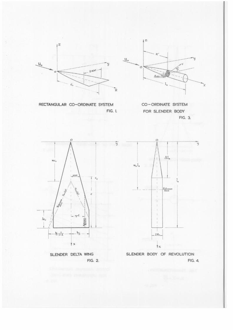
1 distance of reference section from wing root Fig. 2
/B length of body of revolution Fig. 3
(r ‘z)rst(.1 r +'
(r" P(" )rs equivalent constant derivatives Appendix II
c rs
mlmosmb factors giving position of reference axis for wing, tiring-body combination and body respectively Appendix VI
n constants in series expansion for 0 3
Pt P,e, local and freestream pressures 2
61) differential pressure 3
qs Lagrangian generalised coordinates 4
r polar, radial, coordinate 7
r)s indices and suffices in modal functions 4
s(x) local wing semispan Fig. 1

so 112
se lIathieu function (periodic) 3
t time
ulviw perturbation velocities 2
tiv with suffices - various upwash conditions
xlysz right-handed Cartesian coordinates Fig.
xo(Y) equation of reference axis 4
zo amplitude at reference section in flexural mode 4
I ` (x) local cross-sectional area of body 7
n factor giving length of conical nose on body Fig. 4
II = - .7.71. 7
ao amplitude at reference section in torsional mode 4.
pr functions of X Appendix III
y ssb ,e flutter force coefficients 4 rs rs
8
non-dimensional spanwise parameter 4.
diriensionless amplitude or thickness 2
elliptical coordinate; polar angle 3 and 7
elliptical coordinate 3
2k 7 a -
7%, delta planform factor Fig. 2
v angular frequency 3
P local and free stream densities 2 Ps or,
= —o ratio of max. body radius to so max. wing span 7

-6-
position of reference section
= T.b/2 Appendix I
0 perturbation velocity potential 2
wowr, ,w local, root and mean frequency parameters 2
vc
we = wr = U r , etc. Suffix c is used. for fx) wing-body combination in place of 'r' Appendix V
1. Introduction
In this paper a method is given whereby the aero-dynamic forces can be calculated for slender, low aspect ratio wings deforming harmonically in a compressible flow.
The method is applied to a slender, cropped, delta wing and certain flutter modes are assumed which take the form of polynomials in the spa vise parameter. Freedom of the wing root is allowed for so that body freedoms can be included. In the latter part of the paper the aerodyn-amic forces on a pitching and plunging, slender, udng-body combination are evaluated.
The basis of the method is the 'Slender-Body Theory' which has been applied in connection with the (quasi-steady) stability derivatives for slender, wings and wing-body com-binations (refs. 1,2,3,45,6).
The application to an oscillating and defaming wing has, very recently, been studied by lierbt and Landahl (ref. 8).
The solution of the 'cross-sectional' problem, for the wing, is analogous to that of a two-dimensional flat plate oscillating in a compressible flow and has been treated. by Ti mane (ref. 9) and Reissner (ref. 10).
The use of the 'Slender-Body Theory' allows the
s Only the regular part of their solution is reouired in this case.

-7-
analysis to apply at subsonic and supersonic speeds subject to u-rtain restrictions on Aspect Ratio, Llach number, Frequency Parameter, Slenderness. Validity at subsonic Speeds depends on an approximate satisfaction of the Kutta-Jowkowski condition.
The assumptions of linearised, thin aerofoil theory are used, the fluid is perfect, the flow irrotational and harmonic motions are considered throughout.
2. The Slender-Body Theory
The coordinate system used is shown in Figure 1 where right-handed rectangular axes are drawn from an origin, 0, fixed in the wing, with the x-axis parallel to the main stream and the z-axis upward. It is assumed that the wing is a thin, flat plate oscillating about its position of zero incidence in the plane z = 0, but always lying in the immediate vicinity of the plane.
The perturbation velocity potential, 0, satisfies the equation
2d 1
a
, a 2
—1 0
2 Oc Ox + dt (2.1)
The conditions holding at the surface of the wing are specified by a prescribed tdownwashi w(xly,01t) and the stipulation that the relative normal velocity of the a-ir and of the wing is zero.
Applying the assumptions of the 'Slender Bo Theory' implies that the x-derivativesin equation (2.1) are neglected and the two-dimensional flow at any cross-section is then given by the wave equation,
91)'yy °zz = 12 °-tt a
The approximation equation (2.2) is satisfied (ref. 13,5) if:
' 2 -e" ' I dx) a; (2.3)a
where IT is the freestream number and s is the -09 local semi-span, or for a triangular wing if
11 - I AR 2 < < 16 (2.3)b
where AR. is the aspect ratio.
(2.2)
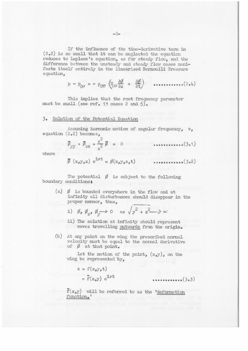
If the influence of the time-derivative term in (2.2) is so small that it can be neglected the equation reduces to Laplace's equation, as for steady flow, and the difference between the unsteady and steady flow cases mani-fests itself entirely in the linearised Bernoulli Pressure equation,
r roo = - R90 ,:t.)ax at
(2.4)
This implies that the root frequency parameter must be small (see ref. 11 cases 2 and 5).
3. Solution of the Potential Equation
Assuming harmonic motion of angular frequency, v, equation (2.2) becomes,
2 7YY
+ 7zz + ?2 = o (3.1 ) a
where ivt e 7 (x,y,z) = 0(x,y0z,t)
(3.2)
The potential 0 is subject to the following boundary conditions'
(a) 0 is bounded everywhere in the flow and at infinity all disturbances should. disappear in the proper manner, thus,
i) 0, 0, 0 as v/ y2 + z2
ii)
The solution at infinity should represent waves travelling outwards from the origin.
(b) At any point on the wing the prescribed normal velocity must be equal to the normal derivative of QS at that point.
Let the motion of the point, (x,y) on the wing be represented by,
z = f(x,y,t)
T(x,y) eivt
(3.3)
7(x,y) will be referred to as the 'deformation function.'

(3.4) Z.(x,y) = iv T(xly) + 7_ ilx(x,y)
?x(x,Y) .•(3.5) 7/(x0 y) = k(xly,0) = iv?(x,y) U
with ..(3.7) k vs 2a
-9-
According to the usual assumptions of the linearised theory the vertical velocity of the point (x,y) is given by,
az 3z az w - - + U dt tat 470 ax
r- -1 ivil(x0y) + U T (x y) f e ivt 00 x '
or,
The condition is satisfied overihe projection of the wring in the plane z = 0 and takes the form,
(c) Outside the wing and outside the wake 0(x0y,z,t) must be continuous in planes, x = constant, and since it is antisymmetric in z must satisfy the condition,
0(x„y10,t) = 0 .
By transforming equation (3.1) to the Miptical Coordinates, (,71), where;
y= s cosh 1-1 cos 4')
z = s sinh T1 sin
and s(x) is the local semi span, Merbt and Landahl (Ref 8) have derived a solution in terms of Mathieu functions.
the notation takes the form, r.
7(x,T1,4) = pn n=1
* The use of a 'bar' over a symbol denotes that it is the amplitude of the harmonically oscillating quantity represented by the symbol itself.
of reference 18 the solution
Ne(2) (11,k) sen (4k)
(3.6)

-1 0-
where the coefficients, pn, are to be determined from boundary condltion ;b), equation (3.5) which becomes in elliptical coordinates,
7 (x,0,4) = s(x) I7 (xo s cos 4) sin
(3.8)
Differentiating (3.7) with respect to n and putting T1 = 0 (on the wing) gives.-
7 (x,0,4), pn' rNen(2)(11 k)j sen( ok) ;i an n=1
71=0
•a,f.}
= Pn sen(r,,k) n=1
writing,
(3.9)
P (k) = p (Ere(2)(Ili k)' (3.10) n al n 1==0
Now if w(xg) is bounded and is a continuous function of the series representing 7 (x,014) in (3.9) will be uniformly convergent.
Multiplying (3.9) by se (?,k)and integrating over the range, 0 to 7c, the coefficients P may be determined in an analogous manner to Half-Range Fourier Coefficients since an orthogonality relation exists for the liathieu function Ee
n(4,k) (see ref. 16).
The Fn are thus given by;
Pn(k) = acs ; w(x.7 s sen(1,k) d 1 (3.11)
and finally the pn from (3.10).
The solution, (3.7), is now completely determined and the yressure distribution on the wing will be given from (3.7) with rl = 0.
As discussed in section 2 it is possible, under certain conditions, to suppress the time- dependent term in equation (3.1) and,ti-e solution (3.7) then reduces to.-
n1 = e
:1lin sin n4
n=1 (3.12)

where the Ln are given by,
H7L
2s -n lin = 1:"(x) = i a. sin 41. sin x-1;1. d i
(3.13)
On the wing, Ft n
= ez.‘ . sin nc, n-- n .= A
(3.14)
The differential pressure across the wing plane is given as,
...... . . iv .m,A Lip = 2p U, (ff 7 + - • ,00.) (3.15) .1r! .
-,,, N X U , (.1 ' Z=A-0
4. Symmetric Flutter Characteristics Typical of a Slender Delta i4-1E.
The simplest, pointed, low aspect ratio wing satisfying the assumptions of the 'Slender Body Theory' is the slender delta wing.
Accordingly the analysis as developed in section 3 is applied to the wing shown in Figure 2.
To describe the possible flutter modes of the wing a reference axis, xo(y) is used (see Fig. 2) given by the equation,
4.0
xo racr b + - X) (1 - m) 150 (4.1)
The applicability of an axis such as this to delta wings is discussed by ',00dcock (ref. 17).
For any particular flutter motion it is then prescribed that sections parallel to the line of f31g12-1, twist about the reference axis according to some modal function, such sections remaining themselves undistorted, whilst the reference axis itself translates according to another modal function, each degree of freedom so involved being associated with a Lagrangian generalised coordinate, q,.
• Details of the wing are given in Appendix I.

-12-
The generalised coordinates are defined at reference sections given by
ly; = I (4.2)
and all motions are measured relative to the :moan position of the wing (plane, z = 0).
A non dimensional spanwise parameter, 8, is introduced such that
y = 8/
and 16 = 1 at the reference sections.
(4.3)
Each degree of freedom will lead to an equation of motion and a generalised force, . which can be expressed conveniently in terms of force coe ficionts as (omitting eivt),
Qr2 = (-Yrs wm brs crs) p6c
(4.4)
on the assumptions of the linearised theory, where,
s = r = number of degrees of freedom
and wm = mean frecuency parameter
vcm
Note.- cm
is the mean chord of the
1J,J ' c half-wing. See Appendix
In ;hat follows the suffices + and - will indicate whether a fuaction applies only for y > 0 or y 0 respectively.
4.1. Uncoupled Liodes
Let there be one uncoupled M0012 in flexure and one uncoupled mode in torsion described by the modal functions, h(5) and H(8) respectively, so defined that,
h(+ 1)! 1)) = 1 .
If zeivt represents the translation of a point
on the reference axis, measured from the mean position,
* The generalised coordinates and forces are amplitude functions but the bar notation is not used in their case.
(4.5)

z = zoh(5)
a = oH(S) (4.6)
and
and
z o q1 = T
ern q2 = 1 ao
. ( I4 8) T =lhg1 (x-x ) 1 Hq c 2
-15-
positive upwards, and aeivt the rotation, positive leading
edge dawn, of the :action through that point, then,
where zo and ao are the amplitudes at the reference
sections, y = ± Z.
Now, if the generalised coordinates are chosen so that,
then the deformation function P(x,y) of equation 13.3) takes the form,
It will be convenient, for the aerodynamic problem, to consider the functions, h and H, each to be polynomials in 8: thus, for symmetrical modes;
h = gr Sir r
(4.9) II 1 IS = ir" G
s s r s = 0 1 2 0 /
Equation (4.8) becomes, for the half-wing for which y.>-0,
rs"7. ' s) r, - G5 k o+ c s r ni • s i.
(4.10
It is now required to find the two generalised forces Q
1 and Q2.
Thus,
* Q1 8q Ap. (ST ) dx dy (4.11) 1.•
* IS ? indicates that the area of integration is over the wing planform for which 0-e_s(x)(y only,
and

where L ,dr p dx cly; is -Lae total (incremental) aerodynamic force at the poin?., (x,y) on the wing and is given by equation (3.15) when the velocity potential derived for the assumed deformation function is substituted.
From (4.10),
r
(ar" ) Z., g..„8 8q, + qi r •
and the force, Q1, is seen to be built up from a sum of
integrals of the form, 71 _1
!
1 = l2 I p. gr 8r. dx 13-5 (4.12)
S+
In the same way the force, Q2, is expressed as a
sum of integrals of the form
r' -I 2!
1 ,Q2! = ! (x-x0+) Ap. Gs. 8". dx a6 (4.13)
s m
It will be clear that many of the integrals (4.12) and (4.13) will be identical, apart from constant factors.
4.2. Coupled Modes
The deformation function, f , now takes the form:
1 = ih(5) + (x-x o+ c ) H(5) • qr, ..(4.14)
r
there now being r degrees of freedom.
The functions h and H are as defined before in equation (4.9) with r = s so that equation (4.14) becomes,
= q_ 7 gr + \x-x — G 81. ...(4.15) r -r 1 o+ c
m r;
and Q is given by
Qr, 'qr, = 13P (a+)qr dx dy •

-15-
Finally, from (4.15),
2 (x-x ) o+' 11A Qr = ! IP 11. gr cra
S+
. G,1 5r. dx a8
(4.16)
This is a sum of integrals like (4.12) and (4.13).
5. Calculation of the Velocity Potential and the Generalised Forces for the Assumed :lodes of Paragraph 4
The coefficients,
of 7 are given by (3.11) in polynomials of lb!, and following type are met with:
n in the series representation
and since P(x,y) is expressed hence of !yl, integrals of the
icoss 41 sin 41 se n (41' k) (i
'1 •
(5.1 )
Such integrals can be -written as the sum of integrals of the form
; sin • sen(1/k) a41
(5.2)
Using the Fourier Series expansion of sen( lk) integrals such as (5.2) become,
-- i `-> ,) ,z.--:..., JJ (k) I sin r.r16
sin p•11 4' r r=1
s is even (equation 5.1), the limits on (5.3) are 0 to quite straight forwardly, as indicated by equation (3.11) and only a finite number of terms is obtained for (5.1). When s is odd, owing to the assumption of symmetry, the limits on (5,3) reduce to 0 to 7V2 (or 70 to 70 and en infinite series is obtained for (5.3), and hence for (5.1). However, only a few terms need be retained in practice.
The velocity potential on the wing, jc is now fully determined and the corresponding loading is given by equation (3.15).
The generalised forces give rise to integrals like (omitting constants),
f'0 /
x + Uv
v Or dx do
(5.3)
(5.4)

and x x 1-1- tir7) (5.5)
S+
These integrations must, in general, be done by a graphical or numerical means, except when the time-dependent term in the potential eauation (3.6) is suppressed and the Mathieu functions take on their degenerate forms.
The application of the analysis to antisymmetrie flutter nodes follows the same general lines as given for symmetric modes.
5.1. Eauivalent Constant Flutter Derivatives
By analo with the flutter derivatives of two-dimensional (strip) theory it is possible to define a set of 'equivalent constant derivatives'.
These derivatives are constant over the span of the wing and give the correct generalised forces when inter-preted in the conventional sense.
The lift and moment on a strip of unit width are defined in terms of derivatives such as
/ / s' 2" a'
TaZ, m!, Mr! (ref. 1o)
where the 'stiffness' derivatives include the 'inertia' derivatives, 7.! , nt. , 1.. ,
Equivalent constant derivatives,
(1 ) (10) rs rs
etc. (M ) , (ms) p
rs rs
are defined from the force coefficients of equation (4.4) in Appendix
As with the force coefficients the first suffix refers to the generalised force and the second to the mode.
* See Appendix II for discussion of sign convention.

-17-
Apart from the analogy with 'two-dimensional, derivatives the coucept of equivalent constant derivatives is useful in that it facilitates airect comparison of sets of derivatives derived for different modes. For example, direct derivatives in one freedan are rar.de independent of the modes in other freedoms. (See Appendix III).
6. Representative Results
The preceding analysis has been applied to the case of a triangular wing (Fig. 2,T = 0) using uncoupled modes.
Equivalent Constant Derivatives have been calculated for the flexural modes;
h(5) = ; r = 0, 1, 2.
and torsional modes;
H(8) = I8 ; s = 0, 1.
Lodes such as these have been taken pairs, one in flexure, 1811'1 and one in torsion, 151
s 1 giving six
'sets' of derivatives.
The accompanying table of numerical results (Table I) shows the order of the derivatives and their signs (for m = and a set of general expressions for the derivatives is given in Appendix III together with the results of a calculation on a cropped delta for r1 = si = 0 only.
The 'damping' derivatives /a ma and ma are
plotted against 'm' in Figs. 8 9 and 10
By taking r1 = si = 0 and n = 1 the derivatives
are obtained for a rigid pitching and plunging wing referred to the trailing edge - use of the usual transformation formulae then refers the derivatives to any other axis.
This has been done for a triangular wing ("X = 0), a cropped delta (x = 1/7) and a rectangular wing (7■. = 1) for an axis at 0.500 cr and the results are presented in Table II.
In Fig. 11 the'cross-daving' derivatives ma , 1a have been plotted against for these wings.
In this case of a pitching and plunging wing the generalised forces Ql and 02 have simple interpretations '

and do in fact represent the unsteady lift and moment amplitudes on the complete wing, i.e.,
,r7,2
2 x (+vc upwards) p U.S. U2 Z3 r
2 11 2 T2 / 2 (+ve nose dc,..ni.-rtrds)
U. Sc U2 3 cr r v (6.1)
The expressions for lift and moment will be in terms of the dimensionless amplitudes,
Z
i-21 and a c r
and the relevant frequency parameter vall be,
yer 2 \
W = W - I r U +X J
It is convenient in this connection to define a set of force coefficients for rigid motions only since in later paragraphs unsteady lifts and moments on rigid bodies and wing-body combinations arc considered.
Coefficients Lz, L .., etc. are defined by the expressions; z \
9 S - - (Lz iWr z c11
r -! - ((La + L ori,8) ao /
I z iwr112).; + + iwr ao
P S
and these will be referred to as 'Rigid' force coefficients.
As for the definitions giving the equivalent constant derivatives (Appendix II) these rigid force coeff-icients are signed to agree with the normal British flutter sign convention
and
and
0,0 ( 64 2 )

+
I
r
0 I
.0530 1 .0550 1 .0530 .0334 .0334' .03341
2
r s
0 1 2
- (.2r.)-1
.114 .114 i .114
.195 .195 1 .195
int (pR )--1
0 1 .0542 —.0225 —.135 I 1 I.0900 J L-.0405 1
0
-19-
TLDIE
+ /a (AR)-1
r
0
.0296 .00763i.00374 1
.0296 i .007684.00374 0I .781 .996 1.18
2
11,00 .955 ! 1.00
1 1 2
(PR ) -1
1 2
o .003761 .00431.0045o1 1 i .002624-1 .00214-'.00200
r s 0 ►
r 1 2
1 2 0 •786 f .954 ..981 1
0 •735 1,02 1.30 .786 I .954 1.981 1 1 .915 ; •905, .817
0
Derivatives for m = 1. 2) ctin = 0.2

TABU. II
Equivalent Constant De:civatives frrizi .nanund
pitching about an axis at r
Equivalent 1 Triangular Cropped Rectangular 1
Constant i Ang Delta Ling Derivatives
1 1 X=0 'N...=-1 (7X=1) 4
1z - 2
.585 wm
T. 2 - it 2 I - T win 27 Wia 1
(.52L) (.785) 1 i
l 7 7. it
+.735 (.735) (.735)
1
1
-.245wm +.v-L,
T. 2 T.
- if wm + 7 2 + 7,-
(.262) (.785) (.785)
It
+ iir
Z +1.07 (.931) (1.18)
.2Lt +
-7. 2 12
mt wm
.245 wm2
0
(.262)
m -.(345
it it
(.197) (.392)
7z 2 at 2 lc 2 71 20 wm - 7
.137will -.0845 7wra + -7, i
ma
I
(.157) (.197 (.o655)(.392)
IIc It
m - 7 - 7 1
-.386
(.392) (.197) I t !
NOTE: Figures in brackets are decimal equivalents of fractions of it

--21-
7. The Pitching and Plunging Slender lioc T of Revolution
A set of flutter force coefficients for a pointed slender body of revolution can be calculated in an analogous manner to those of the wing by adopting polar coordinates instead of elliptical coordinates when solving the potential equation and in the specification of the boundary conditions.
Probably the only case of interest is the rigid pitching and plunging body and accordingly this case will be dealt with. The cartesian coordinate system for the bony is the same as for the wing and is shown in Figure 3
In each cross-section, x = const., take polar coordinates;
y = r cos 4 )
z = r sin 4 C
then the potential equation (3.6) transforms to
L 1 -2 v2 m
r r = ar or/ + — 2• 7 . c
r g a
(7.1 )
(7.2)
Consider the body movements to consist of a vertical translation (+ve upwards) and pitching about an axis,
x = xo = mB IB
(7.3)
parallel to the y-axis (nose-down pitching +ve).
By analogy with equation (4.6) we define zo to be the amplitude of the displacement of the point, x = xop on the body axis and ao to be the amplitude of
the inclination of the body axis to the Ox axis. Then the motions produce at a point, x, on the body axis the total upward displacement,
(zo + (x-x°) a o) elvt •
Taking the body length, /B, as a reference
length the vertical velocity (equation 3.4) is, zo ( - !Le-.
17(x) = iv /1E t ---1 +; x—xo + . a c. (7.4)
writing r(x) for the local cross-sectional area of the body, the potential near the body takes the form',

The pressure at any point on the surface of the
r ---.R (7) = - 77(x) 1'r. . sin •)u. (7.1- )
-22-
body is
where
( an iv , sin Y P = RX )a x
11(x) w(x) 11(x) (7.6)
The unsteady lift and moment, L and follow by integration of (7.6) along the body.
The 'rigid' force coefficients of equations (6.2) have been calculated for a cylindrical body, with a conical nose as shown in Fig. 24, These are based on the Aspect Ratio of the geometrically similar ting having its root-chord equal to thJ length of the body ana
o R = (see Figure 7) 2 c
where Ro is the maximum (base) raclius of the body.
The coefficients are given in Appendix IV.
By putting Cr = 1 and 1.\ = (1-x) it will be seen that the expressions of Appendix TV are identical with those that would be given for the rigid cropped delta wing using the equivalent constant derivatives of Appendix III with B = 0 and equations (6.1).
8. The SlenclarLLIa.:22qy Combination
8.1 The rigid pitching and 1)1ml:fling combination
A set of 'rigid' force coefficients will now be derived. for the slender wing-body combination shown in Figure 8.
This problem will be dealt with rather differently from the wing and slender body cases in that the velocity potential will be found, not directly as a solution of Laplace's auation, but from the two-dimensional potential for incompressible flow normal to a flat plate.
The required potential will not generally satisfy the two-dimensional wave equation (2.2) and hence the solution will be subject to similar restrictions as the wing solution for k O.

-23-
Using the Joukowski Transformation (see Fig. 6) the velocity potential for the flow around the body config-uration of Fig. 6 (see ref. L) due to a motion w of any section in a fluid at rest oan easily be found and conven-iently expressed in two parts,
--------------------
R2 / 1 2 13(0)=-1-,,/ s2 c 1 4. --- - 4,y2 + wl/
y2
s2i
/ 2 1 s4.
(8.1)
where B(0) is the potential on the body (r=R) and 140 is the potential on the wing (Z; = 0 or 7Z, y = r).
It will be clear that the force coefficients for the wing-body combination of Fig. 5 can be considered to be the addition of two sets of force coefficients; viz.,
(i) the force coefficients for a triangular wing on a cylindrical body, downstreall of the lateral plane through the wing leading edge and body junction.
(ii) the force coefficients for a pointed body upstream of the wing leading edge.
The coefficients (ii) have been calculated in section 7 (
The coefficients (i) can be calculated using (8.1) with the axes and notation of Figure 7.
For the combination, the velocity, TT, will take the some form as for the body alone, i.e. equation (7.4), thus, . ..... ,
I i- zo‘ U. , -
w(x)=ivl lo '--- 1 -xa +"-a 1+ax' (8.2) f ‘ 1 r \ c r; o o iv o' o J
The loading distribution is given by the pressure equation (3.15) and lift and moment by:
1
r 4: i R '.:7
L = i 1 ( l'.1 13)B•dY + (op)N7. CV f ; dx
at ! ...) 0 I., R r
:Is . i cx. r i'li 1 ,
11 = I ; 1 , w
;..:ob ; :..1 o '-'• R „,i r -... (6.3)
and
Appendix IV).
and

Complete expressions for lift and moment on the clyindrical body Ea.:1 triangular wing lead to the 'rigid' farce coefficients which are given in Appendix V. These coefficients like those of the body are based on the triangular wing having root chord, cr, and maximum semispen so = b/2 = Rob'.
The force coefficients for the whole wing-body combination of Figure 5 are given in Appendix VI and the variation of the 'damping' force coefficients L , L. a lid with o- is shown graphically in Fig. 12.
In adding the appropriate coefficients of Appendices IV and V the definitions of Figure 5 and Appendix VI were used and again the triangular wing is used as a basis.
9. Discussion
The use of the 'Slender Body Theory' for unsteady flow problems leads to a solution for the aerodynamic forces which does not involve long computation and many geometrical and other parameters can be carried along in the analysis without having to be specified definitely at the outset.
The restrictions of the theory as discussed in section 2 seem to be somewhat severe but there is evidence to show (ref. 8) that for a rigid triangular wing of aspect ratio, 1, at a Each number of 1.25 and far a frecuency parameter, w up to 6, the theory appears to be quite valid. PurtEermore„ results for an aspect ratio of 0.5 show that when the time derivative terms are neglected the results differ from those given by the complete solution only if w ›. 2 for a Each number range of 0 - 1.25 (rigid triangular
Owing to the need to evaluate several terms of the :Eathieu function series when deriving the full solution it is such longer than the simplified case (for a: allroot frequency pa'rar_leter) and it would always be worthwhile to question whether the full solution is really necessary in any specifiedcase.
With the type of wing to which this analysis can be applied, it is very unlikely that the root frequency parameter will exceed about 0.5 so that in many cases the simplified approach would suffice.
The force coefficients yi,b,c of equation (4.4) are dependent on Liach number and frequency only through the parameter, k, in the general solution, consequently, in

the simplified case which implies that k 0, the coeff- icients are independent of frequency and IJach number.
It has been found, both experimentally and theoretically that the variation of flutter force coefficients with frequency decreases as aspect; ratio decreases so that this is not a surprising result from a theory which is correct for 1R---0.
The preceding remarks can be taken to apply equally well, in principle, to the wing-body combination.
It is interesting to note that the analysis used by Lawrence and Gerber (ref. 1 -.5) (subsonic) when taken to the limit A2----R.0 gives results for a rigid wing which agree with those found here and by Garrick (ref. 1/0.
In this connection it is also interesting to study their results when plotted rAgainst aspect ratio. The slopes of the curves (force coefficients) at zero aspect ratio are correctly those given by /Slender Body Theory' but, in general, the curves depart from their original tangents extremely rapidly. It might be suggested therefore that force coefficients derived using 'Slender Body Theory', if applied outside their range of reasonable validity, will give magnitudes which, in general, will be very different from the 'true' values. (See also refs. 20 and 21 for which AR = 3).
Fig. 10 shows that for an axis at the trailing edge of the wing, no matter which torsional modes are chosen, the direct damping derivative ml is zero indicating that an undamped pitching oscillation would be possible - for all axis positions 0 -.4:m .1 the derivative gives positive damping.
\Then co---71:. 0 the /rigid' force coefficients give the values of lif and moment for the steady case as found by Jones, Spreiter and others (refs. 7 and 2A-.)

- 26-
REFERENCES
No. Author Title etc.
1. Ribner, H.S. The stability derivatives of low aspect ratio triangular wings at subsonic and supersonic speeds. N.A.C.A. - T.N. 1423.
2. Smith and Beane Damping in pitch of bodies of rev- olution at supersonic speeds. Inst.Aero.Scs. Preprint 311 (Feb. 1951).
3. Nonwciler: T.R.F. Theoretical stability derivatives of a highly swept delta wing and slender-body combination. C. of A. Report No. 50.
4. Spreiter, J.R. Aerodynamic properties of slender wing; body combinations at .subsonic, transonic and supersonic speeds. N.A.C.A. T.N. 1662.
5. Henderson: A. Pitching moment C and Cma at mg.
supersonic speeds for a slender delta wing and slender body combination and approximate solutions for broad delta wing and slender body. N.A.C.A. - T.N. 2553.
6. Ribner, H.S., Malvestuto, F.S.
Stability derivatives of triangular wings at supersonic speeds. N.k.C.A. 908.
7. Jones, R.T. Properties of low aspect ratio wings at speeds below and above the speed of sound.
1032.
8. lierbt, H., Landahl,
Aerodynamic forces on oscillating low aspect ratio wings in compressible flow. K.T.H. Aero. T.N. 30.
9. Timman: Aerodynamic coefficients of an oscill- Van de Voeren, ating aerofoil in two-dimensional Greidanus. subsonic flow.
Journ.Aero.Scs. December 1951.
10. Reissner, E. On the application of ilatbieu functions in the theory of subsonic compressible flaw past oscillating aerofoils. N.A.C.A. - T.N. 2363.

at Author
- 27 28 -
Title etc
11 Lin, C.C. On two-dimensional non-steady motion of Reissner, E., Tsien, H.S.
a slender body in a compressible fluid. Jnl. Maths, and Physics. Vol. 27, 1948
12 Ward. G.N. Supersonic flea past slender pointed bodies. Quart Jnl. Mechs. & App. Maths., 2, 1949
13 Miles, J.V.r. On non-steady motion of slender bodies, Aeronautical Quart. 2, November 1950
124, Garrick, I.E. Some research on high-speed flutter. 3rd. Anglo-American Lem. Conf. 1951
15 Lomax, H. Theoretical aerodynamic characteristics of Byrd, P.F. a family of slender wing tail body
combinations. Tech. Note 2554
16. McLachlan Theory & application of Mathieu functions. Clarendon Press. Oxford. 1947
17. 7oodcock, D.L. Symmetric flutter characteristics of a hypothetical delta wing. R.A.E. Report Structures 68.
18. Templeton, H. The technique of flutter calculations. R.A.E. Report Structures 37.
19. Lawrence, H.R. The aerodynamic forces on low aspect Gerber, E.H. ratio wings
Jnl. Aero. Scs, November, 1952
20. Woodcock, D.L. Aerodynamic derivatives for a delta wing oscillating; in elastic modes.
Report Structures 132 21. Lehrian, D.E. Aerodynamic coeff...cients fcr an
oscillating delta wing. Report 14,156. July 1951

-29-
APPEDIX I
The Cropped Delta -
Definitions and Geometrical Properties
See Figure 2 : -
flean chord, cm = 2 cr (1 + X)
Area S = b cm 0
Aspect Ratio, AR = -s-- =
thus,
and
Local semispan, s .x for, 2c (1-.X)
0 (x <(1.-X)c (4)
Reference section position, 1 = rt. 7 (5)
Spanwise parameter, 8 = (6)
2c Local chord, c =
ra . (1 - T(1-7)5) (7) (1+?.)
Ratio, "E (0) 2
2c Reference Axis, xo = mcr + b r (1-.X)(1-m) hr
= A + B
A 2m c
m 1+?,
bB h (1- /0 -
-0 (1-m) (1+1■.)
vc Fresuency parameter, cora = ff-----
(11ean)

-30-
APPENDIX II
Equivalent Constant Derivatives - Definitions
The following equivalent constant derivatives are appropriate to a system with the usual British sign convention i.e. z•axis downward, lift positive upwards, moment and angle of attack positive nose-up.
(a) Uncoupled Kodes
i. One mode in flexure, one node in torsion
0/T I (-1,11 211 "11) = z h
2 d3 1 0
/T
(-y w2 + = I 2- h.H. do
12 m 019) C ,.t 0
2 .117-E
c (-Y21% 021) = (-mz H.h do
m
2 2 (-Y.22% c22) = (—na ) (-.\) H2.
(18 c- 0
017-c
b11 =com. 1 —.h
2 d5 11 m c 0
/I- 2 ( b12 wm = wm I8
t/
h.H. dO c ! o
2 b21 wm = wm (-u/) j I H.h. as
7-u
b22 wr a = w (—Lie) c 3 ° . .0 1
ii. r modes in flexure, s modes in torsion
Derivatives such as (/z) 4 and (mz) rr sr

will be defined in the same manner as in (i) by integrals such as,
10/T
hr
hr' do and 1
Hs., d5 respectively. rj 0 o
(b) Coupled Modes
WT
etc.
(-y w2 + c ) rs m rs lz
2 (-yrs w + c ) m rs la
(b rs ) m = w (l.0 rs m / a
=
=
) rs
(1z) i
rs : : 0
(1a)
rs , , .
r/T
(2-) ,c i L -, .
h
'OA
I --- 0
2
# .,
. r
n
h r
h (18 s
hr Hs dO
H d5 s
etc. - by analogy -s,/ith (a)i■
A term such as (-y w2 + crs) is obtained from rs m /z the real part of the term in the total expression for Qr
which involves both hr and hs ; and (brs wm)/ is obtained
fram the imaginary part of the same tern: other terms are obtained in a similar manner.

-32-
AFFENDIX III
Results of a calculation using uncoupled modes
(a) Equivalent Constant Derivatives for Triangular Lang (7\.=0)
Flexural mode h(s) = 15f r = 0,1,2
1 Torsional mode 11(&) = 15,
i s s = 0,1.
x.=0, s=0
It 2 2z - Twin Al
=
2
(.863 - 1.36n) w2
AR
(1.82 - 1.15m) AR
m z
rah
n
=
=
=
2 2 (.288 - .455m) tom • LP
(.121 - ■288m) AR
.22=2(.0710 - .200m + .158m2) w2
— (.243 — .5761
m , (—•353 + .703m — .354m2) A2
-1, s_ 0
- z 5.x m
- L _
lc 3t(— .139 + .2050 w2 .333
5 1 R
.

ma
= 4 2(.0711 •
-33—
+ 3 (.516 — .349m) AR
= 3 ( . 139 — 205m ) AR
= — 3 (.182 — .3491) AR
ma 11((.142 .40Cm + .317m2) w2 4 )
+ (— .121 + .288m) AR J
ml = .353 + .703m — .3542) AR
r = 2, U =0
1z — 168 57c 2 AD
l + 1
/a = — )1.71 (.490 .690m) —
m
1. — - :12_7c (
.690 — .49cm) IR a 16
mz ( .082 — 115m) w J.
12E
-
4 6 ( 0730 — .123m) AR
AR .06251
- .200m + .15812)
- ( .121 — .288m); Al
m8 — 7c (.178 — .354m + .17612)
r = 0, s = 1.
I z =-6 com AR 7C 2
mz

/a =— 3
la = + 3
mz = 3
= - 3
j-,( .220 - .353m) w2 - .333 {.
(.)r/12 - .274m) AR
( .110 - .176) wri2
(.107 - .274 ►) AR
ma
= :18 (' 00359 - .0100m + .00800m2 ) w2 2 ' , ) t.
— --- ( .°24.3C — . 0930m) L AR lc
MI = 30 (—.0250 + .04.92m — )
r= 1, s = 1.
1z
2 5n • wm JR
= .
la = - 4 ( .0592 - .0911m) w2 fR la it i
18 (0.51+,0 - 0.355m) AR
nz = 6 (.0395 .o612m) w2 . AR
= — (.0540 — .1 1 8m) IR
) 2 ( . 02 — .080Cm + 064-0m2 ) wm. )
.) („oz,3o - .093orap
2 N ma = 30 (- .0250 + .04.92ra - .0243m )

r = 2 s = 1.
1 - 1 168 wm
/a - I 2 (.0792 - .117m) w2 1.00( Al 2
16 = (.206 - .194m) AR
mz = - 40 (- '600495 .00733m) w2 AR
. 30 (- .0359 .0691m) AR
I 2 2 ma - 2 0. 0287 - .0800m .0640m ) in
- (.011-30 - .0930m AR at
ma = 30 (- .0250 + ■0492m - .0243m2)
(b) E ivalent Constant Derivatives far Cr X, general
d Delta
• SO
r = 0Lzz9...zalL 2
15 = " fit lum
7 = - AR
bB .1., ) 2 'lc m 1 = - I 70 - '8' 0 a 3 in 1 - n/cm P2I cum - 77 -- (.
Di-m2 ( 2 A
1+X -i-X2 -14- 1 c 3 + "w
hi7
- m - .nic ;2bB) Al
in'
,7 1 0 L _ b B N 2 j, ' 3 cm '1 .x / cm '2) wm '''
za =
=

(1▪
+
.,02 ) + b B + LI
- 4.cra -A /e ra;
1+X+X2
1.74.
( 1 -- (1+X) 2 ) ' r,2 b B _ P 14. 2 3 c 3 / cm 9/
b B 3
P. is 'p2 M c , c 1 7tc
11
\ B A b B 2 Ric
-:1 - 7A17 fl910) w Q6 c Q2
L F" .fa -...
0
iA. bB .) ( m + , -.r + ‘.. 4 2.1% + 67t lc ) c
f ..,
7c(11-7,,,)- i _ A ., - b B i ma = n -, \ (07+1-73 - 7— p24_ .Ricra • P5) 2(1-ovi-N`+x-') , -.7.
2 b B 2 4cM 1+X. +
; cn 37. corn
bB; ; 2 c;
A ,3 b B 6, • 1+X
+ P2 c
1:1 Locle
1 + 2 where; /31 - 71+7
X
1 + 3X - 12(1+X)
1 + -
4-(1+X) 2
1 - X 3 • 5 3(1+X)
1 + 8X 2
15(1+X)2
3 - 2X +
4(1 + X.)2
(1 + 21. - + 2/3 X.21
5(1+X)3
P,
2
'616
Q7
P8

_77_
(1 5x 7.2/2 2, 9 — ,2
15(1 + X)
1 4X 1310 — 7577)
Expressions for the above derivatives when = 1/7 are
2 .585 wm AR /z =
1 A =
1a =
Ea =
z =
7Z 4
f7z(.141 - .226m) 2
.211(1.86 1.120 AR
R(.141 - .226m) 0),1 AR
n2 - .8457c (.0944- - .281m) AR
Ta = .845 1(.159 --.38m + •284m2) w
2 a Ta
- (.0944 - .2814 AR
ma = .6457-c (- .325 + .650m - .5251a2) AR

APPENDIX IV
'Rigid' Force Coefficients for a Slender Body of Revolution
with conical nose
(see Figure 4)
Definitions;
Length of body = 113
Length of conical nose =e\ ZB
Reference axis at distanco mB ZI3 from nose
Frequency Parameter wB = v/,AJ.
The force coefficients are based on the wing having a geometrically similar plsnfom to the body, thus;
Ro = and lB = cr,
z z Va so that o = (--o \ and co' U,_
r cl D r,
2 10 2 =- —47 cst— (11B . JR
L = .11R
7c 2 ' 2AmB
L = — )
4 .(!_
--5-- + a
7c / 2 t\\
- 2 - raB ̀..3 ) JR
2 1/ AR
/ 2n IC 2 A2
4 3 2 ; _ r, _ •
. JR
a
_ 2 (\ - 4 '
7 3
7c 2 = ( 1
3 i \ 2 ralf) 2/1mB ) 2
2 \
---- - raB + raB ,/
+ -7-- - 3 I w
15 j B
3 / t

-39-
APPENDIX V
'Rigid' Force Coefficients f2EItL221211EiLag_11112E1 12(1111a9.4 Body
(see Figure 7)
w w c — r vcr L - (:1- - 0-2 - 4- .L 03) (02 IR ti z 3 3
LI . (1 - cr2)2 AR
La
- 11 ( - 2o-2 crk - 2404 2no--) 4_
- ma k if 1 _ 02 .1, 5 _
c 3 3 .-, - (1 - 02)2 I. IR
i La =+ 47 f i (2 - 30-2 + 0-3) - Tric (-I - 0-2
li = 1- ( I (1 ..- 2C2 -1- a4 - 40)'- Lac') z -4. 7
— LI i — — 0- + or (1 2 _3-
-
0 ) co2 . .lipt 3 i f c c ;4, 3
_., i El 1
7C S 1 , . .3 I-N c 2 21 II == - 7 0 — 40— + 3s ) - — (1 - s ) Al 2
i 171 G3 0-4- - 12 cy5) lic = ii 1 — r + 15 i
—
m
211 (1 — 2a2 + s4 - 404 LIT)
I- 2 L I - u2 + L 0,3 — o-
we ma
3
- 2 Li (1 _ ,4.3 + 364.) - 79- (1-02 2
1.1a ( - 02) - rao (1 - o - o-4) m 2 -2- —-- (1 - 2
)2
J2 wc

APFETIDIX VI
'Rigid' Force Coefficients for a Slender 'Ang..,:aly Combination
(see Figure 5)
Definitions.-
Total length of caribination = Vcr (1)
Ratio of body length to wing root chord = ---= T c1B r (2)
But Ver = (/B cr(1-0 ) I see figure 5,
so that from (2),
T = V - (1 - 5)
Also , (-0\ izo /z0■1
=
r, B r'
and
wB = T • we ye
w = - c r U
It is essential that the position of the reference axis should be unique when measured from the apex of the wing
c c r) and from the nose of the body (ni .B
)•
This
requires that (see figure 5) :
DB 13 = IB ccrc c • r (5-m)
i.e. mB = 1
V - 11-m or DB - V - 1 5
Length of conical nose = AlB -Tcr (3)
This gives nose-length as a constant proportion of body length ahead of wing root. If c_ nose length which is a constant, proportion of total combination length is stipulated then I \ must be replaced by an expression of the form;
iv 0-1
V = const. (9)
Note: In the above definitions: T # 0 V * (1-5) (10)
T
_ Z. ( 2- - + 2 3 /
( • - G3 + 0.4 (2
5
- 3 / / 3 rad 2/:\ (1
1-4 El I
C C
2 + G14- I - +
6 mc + 12
- 1l' 3 /
mC
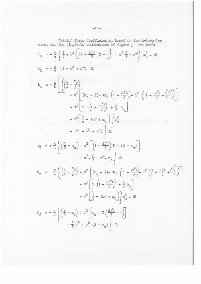
'Rigid' Force Coefficients, based on the triangular wing, for the wing-body combination of figure 5 are then:
L o-2 2
3 - )T - + 0-3 o- ) (002
+ L.
7C L
La 7c 1 (fl _me /.. 1 1 1\7- 3 )
,--- / '-. -- 2i 24 \ )
+ a-1 (mc - ±)- Try 1 - 3 !- L. ...:
= -
+ rjI T - 2 3 mG
/\2) 3 + 4- ,/ H
+ G- 14-1 — /nG + m I (ico2
LA c c
.
- (1 - 0- + Gr 1 .') ..2.
...,
L L r ilL ) 0.21- 1 23 - m _ 1 T ...
a = -F 4 ) \ 3 c
+ „ i_.
(2 - mc) 1 (...
......1
+ 0.3,, 4-.4. .4. . Al .) c
) , 2
Liz = 7' gc 1 07 _2,
- 3c i + G2 (mc - -1-)- Trl ( 1
c / 24\\ 2 ./1 2//\ A - 3)- T ( 7 -
.. 3 + 7-4.),.1
,-. .._„. m. .‘

2
0-2 m (1-. Tm2 h-i 2 4- r
Inc Lac
c c
T2n ( 3 ••-•-- 24./X c 3 2 1
T3 I 1 2/S A2- 21%3 %1
(1 2/.1\" 3 )
2 ;.r) ) I+ cr + (1 —
L... c ;f
-- 0 1:1-- 0 2 f_ !, 2 i 2/\ .A2)-1 + ,y3 — 4.
1 M' alaT (1 - _ . _ T i i ,
- 3 — 2 j
3 3 3, i .,_. ..._
!--c 2 .! ▪ 1 ..
m T 2 - 3 15 coo
m••••J
( ma (1 ,,,c)2
SLENDER DELTA WING
FIG. 2.
SLENDER BODY OF REVOLUTION
FIG. 4.
11
Tx
RECTANGULAR CO-ORDINATE SYSTEM
FIG. I.
CO-ORDINATE SYSTEM
FOR SLENDER BODY
FIG. 3.

1
THE TRANSFORMATION
XI =X+1-cz
FIG. 6.
CROSS' DAMPING DERIVATIVES
FOR DEFORMING WING [?, 0]
FIG. 8.
x
REAR PART OF WING-BODY COMBINATION
FIG. 7
WING-BODY COMBINATION
FIG. S
. p
1
jifiii1111111.1 1111L Wilir 4
M I
11111 I •2
-.dad"
LEGEND:-
pjimmis PE lip
r 01 r ■
2 I
i 6 ■ - -I- - Tr=
s=o
iz
iz.
X, _?ta-u
-2

■ ...._. ...._-- -IIII _Al .. Id
11110r 171 [B-0]
MI .0.1....4 ■KAM ppir. LEGEND:—
TRIAN( CROPP
— — — — — — RECTAI 1 1 J
— 1
0
0
ULAR
ED (),■'—.117)
IGULAR
0 A
'CROSS' DAMPING DERIVATIVES
FOR RIGID WINGS
FIG. I I.
REFERANCE AXIS
—2
1 8 / /
/
/ /
/ / /
o ...--/--
/
. / ..... ...-
1:-
o. ..""
/ ....,
/ /
/ .....-
2 r ..,
.....
6 LEGEND:— R 0 R=1
'CROSS' DAMPING DERIVATIVES
FOR DEFORMING WING +...0]
FIG. 9.
R■■=2
S= I
• 2 • •6 • I. ri
...
...—' — .....„..............-- — — 1
.... ....
.....7
LEGEND:—
S=0 — S= I
RIGID)
I 1
DAMPING DERIVATIVE 171,z
FOR TRIANGULAR WING
FIG. 10.
—
\ 1■44,4
't....
• •4 • c = BODY RADIUS
■ WING SEMISPAN \
\
r. -1/21 < V= 2
■
in.= '12
-o
RELATIVE VALUES OF
DAMPING FORCE COEFFICIENTS
FOR WING - BODY COMBINATION
FIG. 12.
08
0.4
O
—0.4
-0.8
12
—1.6
—2.0
2
0
0•
—0.
- 0.