systems reference library 705/7080 programming … · (cobol), general information, form f2s-s053,...
TRANSCRIPT
Systems Reference Library
IBM 705/7080 Programming Systems
COBOL: Additional Specifications·
This publication, when used with the IBM publication COmmon Business Oriented Language (COBOL), General Information, Form F2S-S053, provides the information required to write COBOL programs for the 705 and 70S0 Data Processing Systems. The information in this publication applies to both the 705S COBOL Processor (#0705-PR-131) and the 70S0 COBOL Processor (#70S0-CB-933). Any differences between these processors are noted, and specific requirements for the individual processors are described.
File Number 70S 0-24 Form J2S-6177-3

MAJOR REVISION (April 1964)
This publication, Form J28-6177 -3, supersedes the previous edition,
Form J28-6177-2, and converts it to Systems Reference Library
(SRL) format. The previous edition is now obsolete. The informa
tion supplied in Technical Newsletter N28-1058 has been incorpo
rated into the present edition.
This edition also includes descriptions of several changes in
the 7080 COBOL Processor that were made subsequent to the
a ppe arance of the technic al newsletter. These changes ate:
1. Hypertape capabilities have been added.
2. The ADD CORRESPONDING and SUBTRACT
CORRESPONDING options have been implemented.
3. The BLIXT macro-instruction (to save and restore storage
banks) is generated automatically in an interrupt program.
4. The implied AT END option of the READ statement is
disallowed. (The 7058 COBOL Processor now produces a warning
message with no other change in former generation.)
Copies of this and other ffiM publications can be obtained through IBM Branch Offices.
Address comments concerning the contents of this pUblication to:
ffiM Corporation, Programming Systems Publications, Dept. D91, PO Box 390, Poughkeepsie, N.Y. 12602
@1961, 1962 by International Business Machines Corporation

INTRODUCTION
Prerequisite Reading Acknowledgement ,.
PHYSICAL DESCRIPTION OF THE PROCESSORS
PROCESSOR-ORIENTED SPECIFICATIONS
General
Identification Division
Environment Division
Configura tion Section
Special-Names Paragraph
Input/Output Section
File -Control Paragraph
I-O-Control Paragraph.
Data Division •
File Description Entries
Record Description Entries
Procedure Division •
Additional Specifications
Procedure Division Verbs
Add Corresponding Option
Subtract Corresponding Option
APPENDIX A: TAPE LABELS AND SPECIALIZED ROUTINES
Label Control Cards
Date Control Card
File Serial Header Control Card
70S III End Control Card
7080 End Control Card •
Labels and Special Processing Considerations
Checking the Record Count
Coding Special Routines When Using the 7080 IOCS
Use of Specialized Routines
Input Files
Output Files
5
5
5
6
7
7
7
7
7
8
9
9
11
13
13
14
17
17
17
19
19
20
20
20
20
20
20
20
20
21
21
21
22
CONTENTS
APPENDIX B: USE OF IOCS 23
70S III Only 23
7080 Only 23
APPENDIX C: PREASSEMBLED IOCS FOR THE 70S III
(7058 COBOL PROCESSOR ONLY) 24
Introduction 24
Assembling an IOCS 24
Macro-Instructions Used in an IOCS Assembly 25
IODEF (Define IOCS) • 25
BLSYS (Include Input/Output Control System) 25
BLHSK (Include Input/Output Housekeeping Section of IOCS) 26
Assembling an Object Program To Be Used With a
Preassembled IOCS 26 Inclusion ofthe 70S IIIPreassembled IOCS With the
Object Program 27
APPENDIX D: PREAS SEMBLED IOCS FOR THE 7080 28
Introduction 28
Assembling an IOCS 28
Assembling an Object Program To Be Used With a
Preassembled IOCS 28
Inclusion of the 7080 Preassembled IOCS With the
Object Program 28
APPENDIX E: DEFERRED ELEMENTS OF THE COBOL
LANGUAGE 29 APPENDIX F: COMPLETE LIST OF COBOL RESERVED
WORDS 30
APPENDIX G: ADDITIONAL CONSIDERATIONS 34
Restrictions on the Use of the COBOL Language 34
Language Incompatibility 34
Verbs 34
Clauses 34
Special Characters 34
INDEX 35


The publication COmmon Business Oriented Language (COBOL), General Information, Form F2B-B053-2, describes the COBOL language in detail but does not supply information pertaining to specific computers or to particular COBOL processors. The present publication provides the programmer with additional specifications he needs to write complete COBOL source programs for the IBM 705 and 70BO Data Processing Systems.
This publication applies to both the 705B COBOL Processor and the 70BO COBOL Processor. Where differences between these processors exist, they are noted, and specific requirements for the individual processors are described. All Hypertape references apply to the 70BO COBOL Processor only.
PREREQUISITE READING
The reader of this publication should be familiar with the contents of the following IBM publications:
COmmon Business Oriented Language (COBOL), General Information, Form F2B-B053
IBM 705/70BO Applied Programming Tape Format and Labeling Standards, Form J2B-6123
Input/Output Control System for the IBM 705 III , Form C2B-6019
IBM 70BO Input/Output Control System for Use with 729 M~entic Tape Units, Form C2B-6237
IBM 70BO InputOutput Control System for 7340 Hypertape Drives -- #70BO-IO-932, Form C2S-6341
ACKNOWLEDGMENT
In accordance with the requirements of the official government manual describing COBOL, the following extract from that manual is presented for the information and guidance of the user:
"This publication is based on the COBOL System developed in 1959 by a committee composed of government users and computer manufacturers. The organizations participating in the original development were:
Air Materiel Command, United States Air Force Bureau of Standards, United States Department
of Commerce Burroughs Corporation David Taylor Model Basin, Bureau of Ships,
United States Navy Electronic Data Processing Division, Minne-
apolis-Honeywell Regulator Company International Business Machines Corporation Radio Corporation of America Sylvania Electric Products, Inc. UNIVAC Division of Spe"rry Rand Corporation
''In addition to the organizations listed above, the following other organizations participated in the work of the Maintenance Group:
INTRODUCTION
Allstate Insurance Company The Bendix Corporation, Computer Division Control Data Corporation E. I. du Pont de Nemours and Company General Electric Company General Motors Corporation Lockheed Aircraft Corporation The National Cash Register Company Philco Corporation Standard Oil Company (New Jersey) United States Steel Corporation
''This COBOL-61 manual is the result of contributions made by all of the above-mentioned organizations. No warranty, expressed or implied, is made by any contributor or by the committee as to the accuracy and functioning of the programming system and language. Moreover, no responsibility is assumed by any contributor, or by the committee, in connection therewith.
''It is reasonable to assume that a number of improvements and additions will be made to COBOL. Every effort will be made to insure that the improvements and corrections will be made in an orderly fashion, with due recognition of existing users' investments in programming. However, this protection can be positively assured only by individual implementors.
"Procedures have been established for the maintenance of COBOL. Inquiries concerning the procedures and the methods for proposing changes should be directed to the Executive Committee of the Conference on Data Systems Languages.
"The authors and copyright holders of the copyrighted material used herein: FLOW-MATIC (Trade-mark of Sperry Rand Corporation), Programming for the UNIVAC ® I and II, Data Automation Systems © 1955, 1959. Sperry Rand Corporation; IBM CommercIal Translator, Form No. F2S-S013, copyrighted 1959 by IBM; FACT, DSI 27A5260-2760, copyrighted 1960 by Minneapolis-Honeywell, have speCifically authorized the use of this material, in whole or in part, in the COBOL specifications. Such authorization extends to the reproduction and use of COBOL specifications in programming manuals or similar publications.
"Any organization interested in reproducing the COBOL report and initial specifications in whole or in part, using ideas taken from this report or utilizing this report as the basis for an instruction manual or any other purpose is free to do so. However, all such organizations are requested to reproduce this section as part of the introduction to the document. Those using a short passage, as in a book review, are requested to mention 'COBOL' in acknowledgment of the source, but need not quote this entire section. "
Introduction 5

PHYSICAL DESCRIPTION OF THE PROCESSORS
A COBOL source program will be compiled by either the 7058 or 7080 COBOL Processor into Autocoder entries in blocked card-image form on tape. The Autocoder entries will then be assembled by the 7058 or 7080 Processor into an object program.
The 7058 COBOL Processor is designed to operate on the 705 II, 705 III, or 7080, and will compile source programs written for the 705 I, 705 II, 705 III or 7080. The 7080 COBOL Processor will operate only on the 7080 and is designed to compile only source programs written for the 7080.
It is always possible to proceed immediately to compilation, but it is generally advisable to make an analysis run first. The analysis run is several times faster than a full compilation, and a listing of all source statements together with diagnostic messages is produced.
During compilation, a listing of the following information will be produced in sequence, along with the object program:
1. A list of Autocoder literals. 2. A transcription of the COBOL Identification
Division. 3. Diagnostic messages from COBOL. 4. A transcription of the COBOL Environment
Division. 5. A list of file-names and their assigned tape
units, followed by IOCS file tables, when the OBJECT-COMPUTER is the 705 III or 7080.
6. The COBOL Data Division entries organized as follows:
6
a. File Section -- for each file and its associated records, a transcription of the File Description entry followed by a transcription of the first record (level 01 and all subordinate Record Description entries), followed by the generated Autocoder entries for the first record; a transcription of the second record, if any, etc.
b. Working-Storage and Constant Sections -- a transcription of the first independent Record Description entry (level 77) followed by its generated Autocoder entries, followed by a transcription of the second independent Recorq Description entry, if any, etc.; a transcription of the first group item (level 01 and all subordinate Record Description entries) followed by its generated Autocoder entries, followed by a transcription of the second group item, if any, etc.
7. The COBOL Procedure Division entries organized as follows: a transcription of each procedural paragraph followed by the generated Autocoder ~ntries for the paragraph.
8. Miscellaneous generated Autocoder entries. 9. Glossaries of cross references between
COBOL names and Autocoder tags generated by the Processor, listed both in order of the source statements and alphabetically by tag name.
The numeric and alphanumeric literals in the COBOL Procedure Division will be converted into Autocoder literals or constants, as required.
GENERAL
The programmer should be aware of the following specifications in coding his COBOL program for the 705/7080:
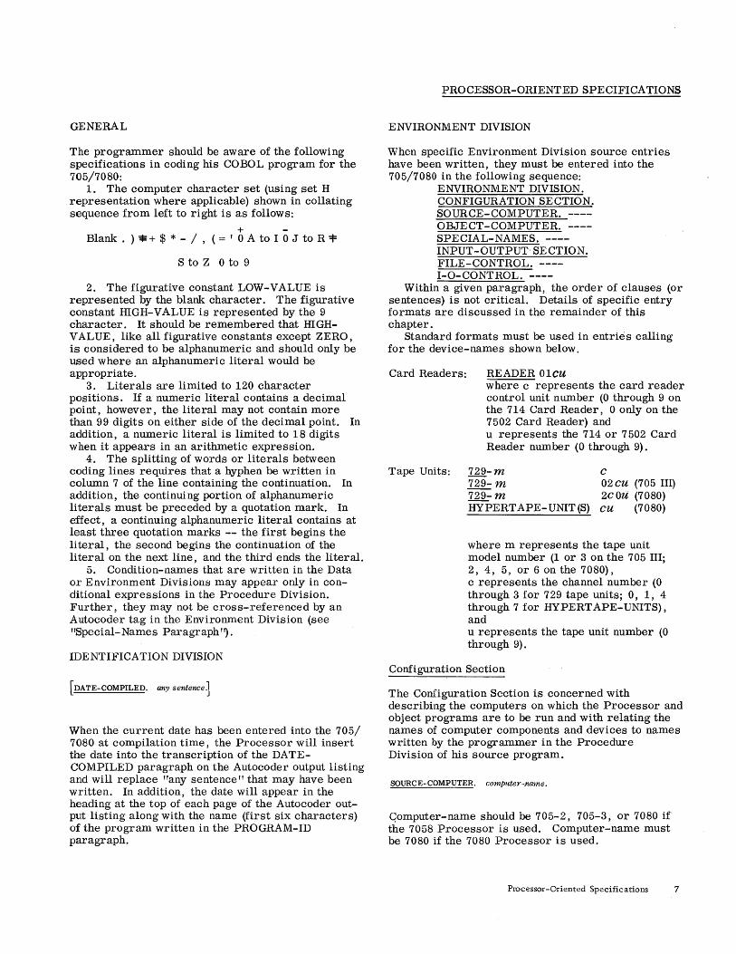
1. The computer character set (using set H representation where applicable) shown in collating sequence from left to right is as follows:
+ -Blank . ) * + $ * - / , (= , 0 A to I 0 J to R "=t=
S to Z 0 to 9
2. The figurative constant LOW-VALUE is represented by the blank character. The figurative constant HIGH-VALUE is represented by the 9 character. It should be remembered that HIGHVAL UE, like all figurative constants except ZERO, is considered to be alphanumeric and should only be used where an alphanumeric literal would be appropriate.
3. Literals are limited to 120 character pOsitions. If a numeric literal contains a decimal point, however, the literal may not contain more than 99 digits on either side of the decimal point. In addition, a numeric literal is limited to 18 digits when it appears in an arithmetic expression.
4. The splitting of words or literals between coding lines requires that a hyphen be written in column 7 of the line containing the continuation. In addition, the continuing portion of alphanumeric literals must be preceded by a quotation mark. In effect, a continuing alphanumeric literal contains at least three quotation marks -- the first begins the literal, the second begins the continuation of the literal on the next line, and the third ends the literal.
5. Condition-names that are written in the Data or Environment Divisions may appear only in conditional expressions in the Procedure Division. Further, they may not be cross-referenced by an Autocoder tag in the Environment Division (see "Special-Names Paragraph'~.
IDENTIFICATION DIVISION
[DATE-COMPILED. any sentence]
When the current date has been entered into the 705/ 7080 at compilation time, the Processor will insert the date into the transcription of the DATECOMPILED paragraph on the Autocoder output listing and will replace "any sentence" that may have been written. In addition, the date will appear in the heading at the top of each page of the Autocoder output listing along with the name (first six characters) of the program written in the PROGRAM-ID paragraph.
PROCESSOR-ORIENTED SPECIFICATIONS
ENVIRONMENT DIVISION
When specific Environment Division source entries have been written, they must be entered into the 705/7080 in the following sequence:
ENVIRONMENT DIVISION. CONFIGURATION SECTION. SOURCE-COMPUTER. ---OBJECT-COMPUTER. ---SPECIAL-NAMES. ---INPUT-OUTPUT- SECTION. FILE-CONTROL. ---I-O-CONTROL. ----
Within a given paragraph, the order of clauses (or sentences) is not critical. Details of specific entry formats are discussed in the remainder of this chapter.
Standard formats must be used in entries calling for the device-names shown below.
Card Readers: READER 01cu where c represents the card reader control unit number (0 through 9 on the 714 Card Reader, 0 only on the 7502 Card Reader) and u represents the 714 or 7502 Card Reader number (0 through 9).
Tape Units: 729-m c 729- m 02 CU (705 III) 729- m 2C Ott (7080) HYPERTAPE- UNIT (S) cu (7080)
where m represents the tape unit model number (lor 3 on the 705 III; 2, 4, 5, or 6 on the 7080), c represents the channel number (0 through 3 for 729 tape units; 0, 1, 4 through 7 for HYPERT APE-UNITS) , and u represents the tape unit number (0 through 9).
Configuration Section
The Configuration Section is concerned with describing the computers on which the Processor and object programs are to be run and with relating the names of computer components and devices to names written by the programmer in the Procedure Division of his source program.
SOURCE-COMPUTER. computer-.name.
Qomputer-name should be 705-2, 705-3, or 7080 if the 7058 Processor is used. Computer-name must be 7080 if the 7080 Processor is used.
Processor-Oriented Specifications 7

OBJECT-COMPUTER. computer-name
Computer-name should be 705-1, 705-2, 705-3, or 7080 if the 7058 Processor is used. If the OBJECTCOMPUTER is a 7080 being operated in 705 III mode, 705-3 should be specified. Computer-name must be 7080 if the 7080 Processor is used.
[ MEMORY SIZE
integer-l CHARACTERS ]
ADDRESS integer-2 [THRU integer-3 ]
The MEMORY option is required only for 705 III or 7080. Integer-1 under the CHARACTERS option should be 40000, 80000, or 160000. Integer-2 under the ADDRESS option represents a program origin (starting point) other than standard on any of the above computer-names. On the 705 I and 705 II, standard origin is 0160. On the 705 III and 7080, the Channel or Tape Tables begin at 0240 and 0500, respectively. If another origin is specified, it will cause the balance of the program (but not the tables) to begin at the specified location. If that location overlaps the tables, the program will originate immediately following them. Integer-3 under the ADDRESS option must be specified on the 705 III or 7080 as 39999, 79999, or 159999.
PREASSEMBLED
1 roes ADDRESS integer-4 I HYPERTAPE-roCS ADDRESS integer-5
roes ADDRESS integer-4 HYPERTAPE-IOes ADDRESS integer-5
IOHSK ADDRESS integer-6 THRU integer-7
When the 705 III or 7080 Input/Output Control System (IOCS) has been preassembled, the PREASSEMBLED IOCS option must be specified. Integer-4, integer-5, and integer-6 represent the starting locations of 729 IOCS, Hypertape IOCS, and IOHSK, respectively. Integer-7 represents the ending location of IOHSK. Integer-6 will also be considered the first address of erasable housekeeping by the Processor and will be used as the starting location of the IOCS output areas.
IOnteger-s TAPE-UNIT(S!] l L.g.nteger-9 HYPERTAPE-UNIT(S~
8
This optional clause is used if the Processor is to check to insure that the number of tapes as signed in the File-Control Section does not exceed the number of available tapes. TAPE- UNIT(S) refers to 729 tape units only.
Special-Names Paragraph
The SPECIAL-NAMES paragraph is never required. If it is written, however, any of the following clauses may. appear:
(!LTERATION-SWITCH 091u [IS mnemonic-name]
[2N STATUS IS condition-name-1J
U?FF STATUS IS condition-name-~ .. J There are six Alteration switches available on the 705 and 7080. The letter u represents the switch number (1 through 6). The mnemonic-name option is required only when condition-name-1 or condition-name-2 is not unique. Mnemonic-name should then be used to qualify the condition-names when referenced in the Procedure Division. Mnemonic-name itself may not be qualified. Condition-names assigned to Alteration switch settings may appear only in conditional expressions in the Procedure Division, and, since the switches are external console switches, they cannot have storage space reserved for them through an entry in the Data Division.
1 READER Olcu l TYPEWRITER
PUNCH 0300
PRINTER 0400
IS mnemonic-name ••.
READEROI CU may be assigned to a mnemonic-name associated with the ACCEPT verb in the Procedure Division.
TYPEWRITER, PRINTER 0400, and PUNCH 0300 may be assigned to a mnemonic-name associated with the DISPLAY verb in the Procedure Division.
Any of the above device-names may be assigned to as many different mnemonic-names as desired, as long as they are correctly associated with the ACCEPT and DISPLAY verbs. Mnemonic-name may not be qualified.
Input/output messages are always displayed on the console typewriter by the 705 III or 7080 IOCS regardless of any device-names specified in this paragraph.

[Autocoder-tag ~ COBOL -name . .. ]
When Autocoder entries are written under an ENTER A UTa CODER statement in the Procedure Division, it may be desirable to refer to COBOL procedurenames or data-names in Autocoder language. This may be accomplished by as signing Autocoder tags to COBOL names in this paragraph. Autocoder tags must satisfy all of the Autocoder rules for defining tags. In addition, they are limited to five characters in length, they may not consist of an alphabetic character followed by four digits, and they may not begin with CS (7080 only), BL, or 10.
COBOL names may be procedure-names or datanames and may include qualification. They may not, however, be condition-names.
It should be remembered that assigning Autocoder tags to COBOL names allows only an Autocoder instruction to reference an item defined in COBOL language. It does not allow a COBOL statement to reference an item defined in Autocoder language. The latter situation requires an ENTER AUTOCODER statement followed by the appropriate Autocoder instruction.
[PROGRAM-START ~ procedure-name]
At object time, program execution normally begins with the first procedure-name written in the Procedure Division (after lacs Housekeeping has been accomplished on the 705 III or 7080). To begin execution at some procedural statement other than the first statement written in the Procedure Division, a procedure-name should be designated as PROGRAM-ST ART under this paragraph.
The procedure-name designated may be a sectionname, or it may be a paragraph-name with or without qualification by a section-name. However, it must not be a paragraph.-name preceding the NOTE verb.
Input/Output Section
In the absence of standard tape-record formats and tape-handling conventions for the 705 I and 705 II, all tape input/output operations must be coded in Autocoder. Using the ENTER AUTOCODER statement in the Procedure Division, the programmer should code his own blocking, deblocking, reading, writing, and label-checking routines. The SPECIAL-NAMES paragraph, as outlined above, will be used to establish equivalences between names of work areas that the programmer has defined in the WorkingStorage Section of the Data Division and the Autocoder tags used in the blocking and deblocking routines.
Input/ output handled by the on-line card reader, card punch, or 717 Printer may, however, be
written in COBOL language for the 705 I and 705 II, as well as the 705 III and 7080, using the appropriate clauses in the FILE-CONTROL paragraph and the File Description entry in the Data Division. The I-a-CONTROL paragraph is not used on either the 705 I or 705 II.
The following discussion of 10CS procedures is directed toward the IBM 705 III and 7080 10CS.
lacs automatically blocks and deblocks records, performs checks, and schedules tape movement for maximum efficiency. A brief discussion of some of the terms used in specifying tape input/output operations follows. The actual method of writing the necessary entries will be covered after this general discussion.
lacs contains a Tape Reel Control System that includes routines for checking inp~t reels to insure that they belong to the proper file and that they are processed in proper sequence. Output reels are checked to make sure valuable information cannot be destroyed through operator error. These checks are regulated by the header (beginning-of-reel) and trailer (end-of-reel or end-of-file) labels.
Standard header labels contain such information as the date the file was written, the length of time the file is to be saved, a file identification, a file serial number, and a reel sequence number, w hereas standard trailer labels contain an end-of-reel or end-of-file indication and a record count. (For complete specifications of standard header and trailer labels, see the Tape Format publication. )
In addition to the information provided by labels, lacs requires such additional information as the current date and the serial numbers of the first reel of each input file. This information must be supplied at object time through label control cards (see Appendix A) that are read either from the card reader or from the beginning of the first reel of an output file. The manner of loading the label control cards is specified in the "File-Control Paragraph. "
Checking of labels is automatic only if labels are standard as specified in the Tape Format publication. If the program uses files with nonstandard or omitted labels, the programmer must provide his own checking routines. He can write these special routines in COBOL language in the Procedure Division (see APPLY under "I-O-Control Paragraph" and Appendix A).
Additional procedures, such as taking checkpoint and dumping unreadable tape records, will be accomplished automatically by lacs if the programmer supplies the necessary entries under the FILECONTROL and I-O-CONTROL paragraphs. Provision for restarting a program that has been interrupted is also made available.
File- Control Paragraph
Every file name referenced in the Procedure Division must be selected and assigned in this paragraph. Input files may be card or tape. Output files may be card, tape, or printer.
Processor-Oriented Specifications 9

~jile-name-l ASSIGN TO
jile-name-2
729-m CO:} ~29-m 1::: I··J I!'0R MULTIPLE REE~
HYPERTAPE-UNIT cu ~TH AUTOLOADE~
READER Olcu
PUNCH 0300
PRINTER 0400
[WITH AUTOLOADEru·· J
The file-name-2 option of ASSIGN implies merely that the tape units assigned to file-name-2 will be assigned to file-name-1. This option may only be utilized in conjunction with tape files and would normally be used to assign an input file to the same units as an output file when these files are to be used sequentially. (See the CLOSE verb in the Procedure Division. )
The MULTIPLE REEL clause has no significance to IOCS and therefore will only be transcribed by the Processor.
Specific assignments must follow these rules: 1. On the 705 III, all tape units assigned to a file
must be of the same model and must be attached to the same channel.
2. For any program, a maximum of five tape units may be assigned to a file.
3. On the 7080, Hypertape units and 729 units may not be mixed for a file.
4. On the 7080, it is recommended (though not required) that all tape units assigned to a file be attached to the same channel.
The remaining options of the ASSIGN clause may be specified for files other than tape.
[RENAMING file-name-3 ]
RENAMING implies that the File and Record Description entries written in the File Section of the Data Division for file-name-3 are to be used in conjunction with file-name-l. However, both files must be selected and assigned, and a tape file may rename only a tape file. This clause would normally be written when the file characteristics of an input and and output file are identical and when both files are to share a common record storage area.
10
File-name-2 under the ASSIGN clause and filename-3 may be the same name only when sequential use of two files is desired. (See the CLOSE verb in the Procedure Division.)
[RESERVE 1~:eger-21 ALTERNATE AREA(S) J
The RESERVE clause is meaningful only when standard IOCS is used on the 705 III or 7080 and the input/output medium is tape. If the clause is not specified, two input/output areas will be reserved. If NO is specified, one input/output area will be reserved. If integer-2 is specified, it may range from 1 through 7, and the total number of areas reserved will be 2 through 8.
Additional File-Control Specifications
Four special "files If may be specified under the FILE-CONTROL paragraph when the 705 III or 7080 IOCS is used. These are files that are under exclusive control of IOCS and must not be referenced by the programmer in the Procedure Division. When these files are specified, the RENAMING and RESERVE clauses are never written. In addition, when a Data Division File Description entry is required, as explained below, the BLOCK, RECORD, and DATA RECORD clauses (as well as the Record Description entries for data records) should never be written. The format and description of each of these special files are as follows.
SELECT ERROR-DUMP ASSIGN TO
1 TYPEWRITER
HYPERTAPE-UNIT cu
1 02cu !
729-m 2cOu
[!nTH AUTOLOADEil!
This file is provided when the programmer wants IOCS to dump tape input records that are unreadable. If TYPEWRITER is assigned, no File Description entry is required. If a tape unit is assigned, it must be a separate tape unit and, as such, a File Description entry is required in order to specify label requirements (and also DENSITY on the 7080). (See also APPLY in the "I -O-Control Paragraph. ") If ERROR-DUMP is not selected, the console typewriter will be assigned automatically.

SELECT RERUN-WORK ASSIGN TO
HYPERTAPE-UNIT cu [WITH AUTOLOADE~
l02CU !
729-m 2cOu
file-name-n
When checkpoints are to be taken, an additional work tape (other than the one containing the checkpoint records) is required. The tape is always repositioned. and assigning an output file as RERUNWORK in no way affects the file. If a separate tape unit is assigned, a File Description entry is required in order to specify label requirements (and also DENSITY on the 7080). No trailer labels may be specified for RERUN-WORK. (See also APPLY in ''I-O-Control Paragraph. ")
If file-name-n is specified, it may be either a source program output file or ERROR-DUMP. If an output file is specified, the file must not be closed until all checkpoints have been passed. If ERRORDUMP is specified, it must have been assigned to a tape unit. No File Description entry is required under this option.
[ 1 READER 01 cu]
SELECT LABEL-DATA ASSIGN TO . . jzle-name-n
As explained in Appendix A, IOCS requires certain control information for automatic checking of standard labels. This information may be entered into the computer from either the card reader or from the first reel of a source program output file. No File Description entry is required under either option. If this statement is omitted and label cards are required, the card reader will be assumed to be the input device.
SELECT RESTART ASSIGN TO
1 READER Olcu
HYPERTAPE-UNIT cu
l02cu! . 729-m 2cOu
GrTH AUTOLOADE~ ! When it is desired to restart a program from a checkpoint, provision should be made for loading the restart program. The restart unit may be either the card reader or a separate tape unit not used for other purposes. No File Description entry is required in either case.
If a tape unit is specified, the tape may have ei ther a standard program tape header (see the Tape Format publication) or no header. If present, the header must contain instructions to space over the tape mark, read the first record of the restart program into storage, and turn off the I/O indicator (IOF) before transferring control to the restart program.
1-0- Control Paragraph
I-O-CONTROL paragraph entries may be specified in conjunction with tape files only when standard IOCS is used on the 705 III or 7080.
APPLY
~GINNING-REEL procedure-name -1 I1HRU procedure-name-m
[iNDING-REEL procedure-name-3 [2:'HRU procedure-name-4j]
~NDING-FILE procedure-name-5 I}'HRU procedure-name-6j]
~LE-PROTEC!J
ON file-name-1
The APPLY clause should be written if certain procedures not a part of IOCS are to be executed at the beginning of each reel of a file, at the end of each reel of a file, or at the end of the file, as appropriate. Each procedure-name refers to the name of a paragraph or section written in the Procedure Division. Each of the above procedures must be self-contained, both logically and physically; i. e., only the IOCS may transfer control to these procedures, and control must be returned to the IOCS when the procedure is completed. No entrance into or exit from these procedures by means of the GO TO or PERFORM verbs is permitted, except that return to the IOCS must be provided by the programmer. The statement GO TO NORMAL-IORETURN or GO TO ALTERNATE-IO-RETURN should be written as the final statement to be executed (see the LABEL RECORD clause in the Data Division and also Appendix A for additional information) . If a given procedure exceeds a single paragraph or section, the THRU option must be written in order to properly define the first and last statements contained within the procedure.
A BEGINNING-REEL entry is required only if a special procedure not a part of 10 CS is to be executed at the beginning of each reel of a file. For example, when nonstandard header labels are used, procedure-name-l (THRU procedure-name-2) must define a procedure for label checking.
An ENDING-REEL entry is required only when a special procedure not a part of 10CS is to be executed at the end of each reel of a file. It will be executed on every reel of an input file and on every reel of an output file except the last. For example,
Processor-Oriented Specifications 11

when trailer labels are not used, a procedure must be written to determine at the end of each reel of an input file whether an end-of-reel or end-of-file condition exists. Procedure-name-3 (THRU procedure-name-4) defines such a procedure. It should be remembered that, on the 705 III, the ENDINGREEL procedure will be executed before the last data record or block of records has been processed; hence, data record counts should not be taken. This restriction does not apply to the 7080.
A procedure to be executed at the end of the last reel of a file is reached by the ENDING-FILE entry. On both the 705 III and 7080, the ENDING-FILE procedure will be executed only after all data records have been processed. If specified for an input file, procedure-name-5 (THRU procedurename-6) will be executed prior to the IOCS transfer of control to the AT END statement. If specified for an output file, the procedure will be executed on a CLOSE statement.
The FILE-PROTECT option is valid only when applied to a Hypertape file. When used, an indicator will be set on the Hypertape cartridge at each end of reel or end of file to prevent subsequent use of that cartridge for output.
RERUN
t {HYPERTAPE_UNIT ell
ON 02eu - 729-rn
- 2cOu
~TH AUTOLOADE~ } ]
EVERY END OF REEL OF file-name-l [rile-name-2 .. J.
12
The 705 II or 7080 IOCS provides for resuming a program that has been interrupted before completion. In order to restart the program, a recording of the complete status of the machine is taken at intervals known as "checkpoints." Checkpoint records are written on the RERUN file, that is, on either the reels of a source program output file or else on a reserved tape unit.
When the ON option is utilized to assign the RERUN file to a separate tape unit, checkpoints will be taken at the end of each reel of each source program input and/or output file-name written after REEL. A File Description entry named RERUN is required in order to specify label requirements (and also DENSITY on the 7080). However, no trailer labels will be allowed under this option. (See the LABEL RECORDS clause in the Data Division and the APP L Y clause above.)
When the ON option is omitted, only file-name-l may be written after REE L. In this case, filename-l must be a source program output file. Checkpoints will be taken at the end of each reel of file-name-l except the last and will be written at the beginning of each alternate reel of file-name-l.
Under either option, the specification of a second tape, known as the RERUN-WORK file, is always required (see "File-Control Paragraph").
Note: If RERUN and/or RERUN-WORK is assigned to a shared Hypertape output file(s), the file(s) will be opened in IOCS Housekeeping prior to execution of the programmer I s initial OPEN statement. Execution of the OPEN statement will cause the file(s) to be re-opened. If a BEGINNING-REEL routine has been specified for either of these files, it will be executed twice.

DA T A DIVISION
The following discussion is concerned with the limitations and specifications of the 705/7080 COBOL Data Division entries.
File Description Entries
File Description entries are the means by which files of data are described to the COBOL Processor. The programmer should be aware of certain considerations in coding such entries for the 705/7080.
Whenever a file is card input, card output, or printer output, the File Description entry consists only of the level indicator FD, the file- name, and the DATA RECORDS clause. Input/output operations for these file types may be coded in COBOL language for all models of the 705/7080.
Tape input/output operations may be coded in COBOL language only for the 705 III and 7080; they must be coded in Autocoder for the 705 I and 705 II. The following entry format specifications are directed toward tape files when the 705 III or 7080 laCS is used.
RECORDING MODE IS
[{:~: } DE~ITY l [pmNTER-72~ G PACKED U UNPACKED UNTERCHANGEABL.J } J
[fHECKPOINi] ~O-LENGTH-CHECKJ
When the OBJECT-COMPUTER is the 7080, HIGH or LOW DENSITY must be specified for each 729 tape file.
When an output file is to contain records prepared for off.,.line printing on a Model 720 or 730 printer, PRINTER-720 should be specified only if the final character in a block of records is a record mark. When PRINTER-720 is specified, the final character in a block of records, regardless of its nature, is deleted. Such files must be written in LOW DENSITY and cannot re-enter the system as input. Therefore, the remaining options are inapplicable.
PACKED or UNPACKED is relevant only for Hypertape files attached to a high-speed channel. PACKED is used if data compression is desired. UNPACKED is used if data compression is to be disallowed. If the option is omitted, PACKED will be assumed.
INTERCHANGEABLE (relevant only for Hypertape files) is used for files containing variable-length
rorrn J""O-O.1II-.:I
Page Revised July 31, 1964
By WL N28-1164
. records in the inter-machine Hypertape format. If this option is used, the RECORDING MODE must be UNPACKED.
When an input file contains checkpoint records, CHECKPOINT must be specified.
Every block of a variable-format tape file must begin with a five-character field, the last two characters of which specify a blocking factor of 99 records or less. The remaining three characters may be used to specify the block size. When the block size is present, it will be checked against the actual block size read into the computer. If the block size is not specified, NO-LENGTH-CHECK must be specified. Since the block size and blocki!1g factor are automatically written onto COBOL output tapes of this type, NO-LENGTH-CHECK should never be specified for input files that were created as output from a previous COBOL run. (See the Tape Format publication. )
~ I RECORD(S) U BLOCK CONTAINS integer-l
CHARACTERS
This clause is required unless a block contains one and only one complete record.
The following rules apply to fixed-length blocks: 1. When RECORD(S) is written, integer-l
represents the exact number of records in each block.
2. When CHARACTERS is written or when RECORD(S) is omitted, integer-l represents the exact number of characters in each block.
The following rules apply to variable-length blocks:
1. When CHARACTERS is written or when RECORD(S) is omitted, integer-l represents the number of characters in the largest block, including the five-character blocking factor field (see the Tape Format publication).
2. When it is desired to control the number of records in a block of an output file, RECORD(S) may be specified, in which case integer-l represents the fixed number of variable-length records in each block. The RECORD clause must also be written and both integer-2 and integer-3 must be specified.
[~CONTAINS rnteger-2 TO] integer-3 CHARACTERS]
This clause is always required when describing variable-length records. Integer-2 represents the number of characters in the smallest record, and integer-3 represents the number of characters in the largest record.
If desired, the RECORD clause may be written when describing fixed-length records. In this case, integer-2 must not be written, and integer-3 represents the exact number of characters in each record.
It should be remembered that each IOCScontrolled record must start in a 0 or 5 memory
Data Division 13

Form J28-6177-3
Page Revised 9/11/64
By TNL N28-1178
LABEL RECORD(S) 1 IS t ARE~
STANDARD
[JEGINNING-TAPE-LABELJ I OMITTED
[!O-TAPEMARKJ i . [ENDING-TAPE-LABELJ ~
location, and, with the exception of unblocked, fixedlength records, must be a multiple of five characters in length and must end with a record mark (see the discussions of SYNCHRONIZED and PICTURE). The LABEL RECORDS clause is required only when the file is assigned to tape. When OMITTED is specified for an input file, the programmer must determine, as part of the end-of-reel routine for each reel, whether an end-of-reel or end-of-file condition exists. It should be remembered that on the 705 III the last record or block of records may not have been processed when the tape mark was sensed and therefore cannot be relied upon to provide end-of-file detection. (See the APPLY clause in "1-0- Control Paragraph. ") STANDARD implies that both header and trailer labels exist and are in the format described in the appropriate 10CS publication. If this clause applies to a Hypertape file, the only valid option is STANDARD. Additional operations may be performed on header and/or trailer labels by defining the labels in Record Description entries with the level 01 fixed datanames BEGINNING-TAPE-LABEL and/or ENDINGTAPE-LABEL for 729 files, and BEGINNINGHYPERTAPE-LABEL and/or ENDING-HYPERTAPELABEL for files assigned to Hypertape drives. (See the APPLY clause in ''I-O-Control Paragraph. ")
The remaining information describing the LABEL RECORDS clause applies only to 729 labels.
Nonstandard label records must be no longer than 80 characters. IOCS will read and write these labels into and from the IOCS label area. The header label named BEGINNING-TAPE-LABEL or the trailer label named ENDING-TAPE-LABEL or both should be specified under the LABEL RECORDS clause. A tape mark will separate trailer label records from data records. Header label records will also be separated from data records by a tape mark unless NO-TAPEMARK is specified. Record Description entries with the level 01 fixed data-names BEGINNING-TAPE-LABEL and/or ENDING-TAPELABE L must be provided. (See the APPLY clause in the "I -O-Control Paragraph. ")
When BEGINNING-TAPE-LABEL and/or ENDINGT APE-LABE L appear as label record names of two or more files, they must be qualified by their associated file-names whenever referenced in the Procedure Division.
No trailer labels will be allowed on RERUNWORK orRERUN files when they are assigned to separate tape units. (See the discussions of FILE-
14
CONTROL and I-O-CONTROL in the Environment Division. )
Header and trailer labels other than the types described above must be named under the DATA RECORDS clause and must be completely programmed as data records. In this case, OMITTED must be specified, and the names BEGINNINGTAPE- LABEL and ENDING-TAPE-LABEL are disallowed. In addition, the automatic end-of-tape indications must be circumvented.
[ m
VALUE OF
IDENTIFICATION
IS 'up to 10 alphanumeric characters excluding special characters'
[PURGE-CYCLE IS up'" 3 digits 1 ]
The VALUE clause must be written when label records are STANDARD. The PURGE-CYCLE option can be written for output files only (see Appendix A).
Record Description Entries
Record Description entries are the means by which items of data are described to the COBOL Processor. The programmer should be aware of certain considerations in coding such entries for the 705/7080. The remainder of this discussion is devoted to specific limitations and interpretations.
[SYNCHRONIZED I LEFT I]
RIGHT
SYNCHRONIZED RIGHT has no Significance to the 705/7080 and will be ignored by the Processor.
SYNCHRONIZED LEFT causes data to be stored beginning in a 0 to 5 memory location. This clause must be written in the File Section when the tape label or data records described are under control of the 705 III or 7080 IOCS (see the discussion of PICTURE). It may also be used in the WorkingStorage and Constant Sections to position data suitably for high-speed transmission. The size of the item must be a multiple of five characters in length and, on the 705 II, must also end in a record mark (see PICTURE).
On the 7080, a level 77 entry containing a SYNCHRONIZED LEFT clause, or a level 01 entry that becomes a left-synchronized as a result of a lower-level entry containing a SYNCHRONIZED LEFT clause, will be assigned memory locations beginning in a 0 position. If the item is a multiple of ten characters in length and ends in a record· mark (see the discussion of PICTURE), the tencharacter transmission feature will be available.

The SYNCHRONIZED clause should be written only in an elementary item Record Description entry; it has no effect on the efficiency of arithmetic operations.
I!>ICTURE IS any allowable combination oj J L COBOL characters and symbols
The PICTURE symbols J and K have special uses on the 705/7080. Both symbols may be required when specifying records in the File Section, and both may be used wherever desired in the Working-Storage and Constant Sections.
Data records that are to be read from or written on tape in blocked format (using the IOCS) must be a multiple of five characters, must be left-synchronized, and must end in a record m ark. Variable-length records must begin with a five-position field containing the data record length (see Tape Format publication).
Note: No more than five digits can be contained within the parentheses after the significant character in a PICTURE clause.
An entry consisting of only a level number, dataname, or FILLER, in combination with the PICTURE IS J clause, will cause the Processor automatically to insert a record mark in the next 4 or 9 memory position. This clause may also be written in Record Description entries in the Working-Storage and Constant Sections when it is desired to take advantage of high-speed transmission, provided that the data is a multiple of five characters and is left-synchronized.
Data records that are to be written on the on-line card punch or 717 Printer must be followed by a group mark. An entry consisting of only a level number, data-name, or FILLER, in combination with the PICTURE IS K clause, will cause the Processor automatically to insert one group mark. Normally, this clause would be written only in the File Section, but under certain circumstances it may be desirable to write it in either the Working-Storage or Constant Sections.
The following interpretations and restrictions are peculiar to 705/7080 Record Description pictorials.
1. Numeric items: a. When the assumed decimal point (V)
appears in a PICTURE, the item may not contain more than 99 positions on either side of the decimal point.
b. When a NUMERIC item appears in an arithmetic expression, it is limited to 18 numeric characters.
2. Report items: a. A report item may not contain more than
18 numeric characters. b. An actual decimal point (.) should not
appear as the rightmost character in a PICTURE. It will be considered a period.
c. The letter Z and an * may not appear in the same PICT URE .
d. The letter Z or an * may be preceded only by another Z or *, respectively, a
Form J28-6177-3
Page Revised 9/11/64
By TNL N28-1178
single $, a comma (,) an actual decimal point (.) or an assumed decimal point (V).
e. The letter Z, a $, or an * may appear to the right of an actual decimal poi nt (.) or an assumed decimal point (V) only if all numeric character positions are represented by Z, $, or *, respectively.
f. The letter Z or an * may not appear in the same PICTURE with more than one $ (floati ng dollar sign).
g. When a PICTURE contains one or more commas, the Processor generates an edited field with a comma after every third character to the left of the decimal point. If there is no decimal point, the Processor generates an edited field with a comma after every third character to the left, assuming the field to be an integer. ill either case, the leftmost character cannot be a Comma. If commas are not specified in the PICTURE, commas will not be generated. For example, a PICTURE containing commas should be written as illustrated below.
With a decimal point: Z, ZZ Z , Z Z Z , Z Z Z . Z Z- or Z Z Z , Z Z Z , ZZZ. ZZ-
With no decimal point: Z,ZZZ,ZZZ,ZZZ, ""'jor ZZZ,
ZZZ,ZZ-Z·~-' '
When the CLASS of an item is NUMERIC, an operational sign, if any, will appear over the units position of the item as a I2-zone ( + ) or II-zone ( - ). The sign of the item will be considered always present if the SIGNED clause or the "S" character in PICTURE is written, and never present otherwise. In order to produce efficient coding for computations, NUMERIC items on the 705/7080 should be signed in the units position and left-protected. Left-protection occurs whenever the rightmost character of the preceding item is not an unsigned digit. If the preceding item, as described by its Record Description entry, does not always contain such a character in the rightmost position, the progranlmer should consider rearranging the data or inserting a blank character. Note that an ALPHABETIC item always affords left-protection to the item on its right, while an ALPHANUMERIC item mayor may not do so.
Elementary non-report ALPHANUMERIC items, which do not always contain an alphabetic character, i. e. , whose PICTURE contains no A's, will be treated as unsigned integers when referenced by an arithmetic verb or when associated with NUMERIC or report items, as in a MOVE operation. A warning message will be produced by the Processor.
Data Division 15

Alphanumeric items of the report type will never contain operational signs over the units position. However, when an arithmetic verb references a report item, an object-time scan of the item will be provided which will extract the numeric contents of the item; taking into account any decimal positions and sign indication. Thus computations are allowed on report items. Similarly, a report item will be moved arithmetically to a NUMERIC item, another report item, or a non-report item, as described above.
[ I COMPUTATIONALI] USAGE IS
!ffijPLAY
Since all data represented within the 705/7080 is in external format, the DISPLAY option of the USAGE clause is not meaningful and will be ignored by the Processor. However, if an item is specified as being COMPUTATIONAL, it must be a NUMERIC item.
[VALUE IS literal]
16
The VAL UE clause has no meaning in a Record Description entry that describes a report item, and it cannot be used to specify an initial value. This restriction also implies that a level 88 conditionname entry cannot be associated with a report item.
When the VALUE clause appears in an entry at the group level, the size of the literal must be equal to the size of the group item, i. e. , the total size of the lower-level items within the group. The group area will be initialized without consideration for the individual elementary or group items contained within this group. The decimal pOint and operational sign must not be written in a numeric literal at the group level. A figurative constant may be specified at the group level only if the SIZ E clause is also written in the entry.
[REDEFINES datu-IIUlIle]
The entries redefining an area must immediately follow the entries originally describing the same area. Multiple redefinitions are possible, however, provided that they occur at the same level and without other entries intervening at that level.
An entry containing the REDEFINES clause must not be written at a lower level within another entry containing a REDEFINES clause, unless the latter entry is at the 01 level, in which case one such lower level redefinition is permitted at a time.

PROCEDURE DIVISION
The following discussion contains specifications concerning 705/7080 COBOL Procedure Division entries. The first part of the discussion contains specifications not included in the COBOL general information publication, whereas the second part discusses Processor limitations and interpretations pertaining to specific verb formats.
Additional Specifications
Data items that appear in relational expressions may not contain more than 255 character positions.
When a data-name written in a Data Division Record Description entry is not unique, it must be qualified by one or more additional names to make it unique, whenever it is referenced in the Procedure Division. A file-name written in a Data Division File Description entry is the highest level name that may be used as a qualifier. In addition a file':':'name that is RENAMING another file-name in the Environment Division FILE-CONTROL paragraph may be used as a qualifier for an associated Data Division data-name.
When the OCCURS clause is written in a Data Division Record Description entry, the name of the item can be referenced in the Procedure Division by means of subscripting only. In addition, any item that is subordinate to an item described by the OCCURS clause must also be referenced in the Procedure Division by means of subscripting.
When the OBJECT-COMPUTER is a 705 I or 705 II, the OPEN, READ, WRITE, and CLOSE verbs may only be written in conjunction with card input, card output, or printer output files.
The Class Condition IF data-name NUMERIC (ALPHABETIC) . . . may be used only to test an ALPHANUMEIUC item at object time to determine whether it is wholly numeric or wholly alphabetic in content. An item will be considered NUMERIC if it consists of unsigned digits only or if all character positions except the units position are unsigned digits and the units position contains one of the digits o through 9 with a 12-zone ( + ) or II-zone ( - ). It is therefore possible for a one-character data item to be considered NUMERIC or ALPHABETIC depending upon which test is made.
Conditional statements may be written in three basic forms, as shown in Figure 1.
Option 1 IF conditional expression statement-l.
Statement-l can be only a simple or compound imperative statement.
State me nt- 2, statement-3, and statement-7 can be either imperative or conditional. If conditional, they can, in turn, contain conditional statements in arbitrary depth. When the statements are conditional, the conditions within them are "nested. "
Statement-4 must be a READ statement, statement-5 must be an arithmetic statement, and statement-6 can be only a simple or compound imperative statement. Statement- 8 followed by statement-9 (to which the previous paragraph applies since it is conditional) is an illustration of an imperative statement followed by a conditional statement. This is logically equivalent to statement-8 followed by a period followed by statement-9 beginning a new sentence. Option 3 in its entirety may be substituted for statement-2 and/or statement-3 under option 2.
It is important to note that, when conditional statements are nested, an ELSE or OTHERWISE is always associated with the IF, READ, or arithmetic verb with ON SIZE ERROR that most closely pre ... cedes it. An ELSE or OTHERWISE must be explicitly written for every conditional statement within a sentence. However, the phrase ELSE (OTHERWISE) NEXT SENTENCE may be eliminated if and only if the phrase immediately precedes the period ending a sentence.
Procedure Division Verbs
The remainder of this chapter discusses specific verb format limitations and interpretations that the programmer should understand before he incorporates such verbs into his 705/7080 source program.
ACCEPT data-name [FROM mnemonic-name]
The standard ACCEPT device on the 705/7080 is the card reader. When the FROM option is not written, the card reader address 0100 will be assumed by the Processor. (See the "Special-Names Paragraph. ")
Since the AT END clause may only be written in conjunction with the READ verb, the programmer must provide his own end-of-file procedures when using ACCEPT.
I statement-2 I rTHERWISE I rtatement-3 I Option 2 !¥ conditional expression
NEXT SENTENCE ELSE NEXT SENTENCE
Option 3
I statement-4 AT END II statement-6 I I OTHERWISE II statement-7 I statement-5 ON SIZE ERROR NEXT SENTENCE ELSE NEXT SENTENCE
any imperative statement-8 followed by any conditional statement-9
Figure 1. Conditional Statement Options
Procedure Division 17

DISPLAY ldata-name-lj [ldata-name-2j . .. J literal-l literal-2
[UPON mnemonic -name]
The standard DISPLAY device on the 705/7080 is the console typewriter. When the UPON option is not written, the typewriter address 0500 will be assumed by the Processor. (See "Special-Names Paragraph. ")
WRITE record-name [FROM area-name]
When record-name is associated with more than one output file, either explicitly by means of the DATA RECORDS clause in the File Description entry or implicitly by means of the FILE-CONTROL paragraph RENAMING option. it must always be qualified by the appropriate file-name.
The FROM option implies that the area-name will be moved directly to the file output area associated with the record-name. The record-name area will be left unchanged.
CLOSE file-name-l [WITH LOCK] [file-name-2 ... ]
At the present time, the LOCK option is the only available option of the CLOSE verb permitted for use with the 705 Ill/7080 IOCS. If LOCK is specified, all reels of a file will be made unavailable for reading or writing when the CLOSE verb is executed and when intermediate reels of a file reach the physical end of tape. A subsequent attempt to OPEN a locked file will be rejected. If any CLOSE verb referencing a file uses the LOCK option, all CLOSE verbs for that file will be interpreted by the Processor as having used the LOCK option,.
When a reel or a series of reels is to contain both input and output files within the course of a program, i. e. , when an output file created by the program is to be read as an input file or when an input file used by the program is to be written over as an output file, the LOCK option is appro-priate only when closing the last file. In addition, each file must have a unique file-name.
ENTER language -name
For all models of the 705 and 7080, the programmer may code in Autocoder language. In fact, all input/ output operations for tape files must be coded in
18
Autocoder on the 705 I and 705 II. In Autocoder the programmer has access to the FORTRAN language, the Report/File and Decision languages, and all other special languages normally available. Autocoder entries may be placed anywhere within the Procedure Division, provided each group of entries is preceded by the statement ENTER AUTOCODER and terminated by a COBOL paragraph whose first statement is ENTER COBOL. When the Procedure Division ends with a group of Autocoder entries, a final paragraph-name followed by the sentence . ENTER COBOL must be written. The names AUTOCODER and COBOL are the only language-names permitted with the ENTER verb.
A paragraph-name associated with an ENTER A UTOCODER statement may be referenced directly in COBOL language by the GO TO and PERFORM verbs. A paragraph-name associated with an ENTER COBOL statement may only be referenced indirectly in Autocoder language. An Autocoder tag should be assigned to the COBOL paragraph-na:rne in the SPECIAL-NAMES paragraph of the Environment Division.
The 705/7080 Auxiliary Storage Unit (ASU) settings are determined by the COBOL Processor. ASU 01 through ASU 05 are set to one to five positions, respectively. ASU 13 is set to ten and ASU 14 is set to four. These settings are fixed in each program. ASU 15 and the accumulator are used as variablelength storage units.
The settings of ASU 06 through ASU 12 normally vary from one source program to another. These ASUs will be set by the Processor according to the sizes of items most frequently referenced in the Procedure Division. However, it is possible to preset any of these ASUs by modifying the Autocoder Communication Word prior to compiling the COBOL source program. The Processor will honor such settings and compile accordingly.
When a programmer wants to write in Autocoder language by means of the ENTER AUTOCODER statement, he may wish to alter the settings of certain ASUs for that phase of the program. This is permissible as long as the Autocoder ASU macroinstruction is never written and as long as those ASUs that have been altered by Autocoder instructions are reset by the programmer before returning to the COBOL language.
The required settings of ASUs 01 through 05 and 13 and 14 are known at the time the program is being written. They may be reset accordingly. However, the settings of ASU 06 through ASU 12 are not available until the program has been compiled. In order for the programmer to be able to reset any of these ASUs without prior knowledge of their ultimate settings, specific Autocoder tags have been assigned to each setting. BLASU06 through BLASU12 may be written as the operands of Autocoder SET instructions in order to reset the appropriate ASUs. The numeric columns (21 and 22) of the Autocoder coding sheet should contain a number from 06 to 12 that identifies the ASU involved.

literal
It is recommended that STOP RUN be written in every source program to indicate the end of the program.
On the 705 III or 7080, STOP RUN initiates IOCS end-of-job procedures (such as closing the checkpoint tape) before the final halt is reached.
On all models of the 705/7080, the message END OF RUN will be displayed on the console typewriter and a STOP 9999 followed by a transfer back to the stop will be produced by the Processor.
Add Corresponding Option
The CORRESPONDING option of the ADD verb allows the programmer to specify the addition of corresponding items in one operation in a manner similar to MOVE CORRESPONDING.
The general form of ADD CORRESPONDING is:
ADD CORRESPONDING data-name-l TO data-name-2
~OUNDEDJ tN SIZE ERROR any imperative statement]
Numeric elementary items within data-name-l are added to numeric elementary items with matching names in data-name-2. Data-name-l and dataname-2 must be nonelementary items. The rules stated for the simple ADD verb apply to each pair of items in the ADD CORRESPONDING option.
Only the initial description of items in data-name-1 and data-name-2 is considered in the implementation of the ADD CORRESPONDING option. That is, where a REDEFINES clause has been used within data-name-l or data-name-2, the description of the data contained within the REDEFINES clause is ignored by ADD CORRESPONDING. The ROUNDED option and the SIZE ERROR option may be used with ADD CORRESPONDING. For a detailed description of these options, the reader is referred to the COBOL general information publication.
Note: The SIZE ERROR test is made only after the completion of all the add operations. If any of the additions produced a SIZE ERROR, the resultant field for that add remains unchanged and the "any imperative statement" is executed.
To illustrate the use of the ADD CORRESPONDING option, assume that the programmer wishes to add items from a work area named RE CEIPTS to corresponding items in an area designated STOCK-ONHAND. The programmer could write this statement:
ADD CORRESPONDING RECEIPTS TO STOCK-aN-HAND
Figure 2 shows what will result from this statement. Note that noncorresponding items in the STOCK-ONHAND area are not affected.
RECEIPTS
STOCK-ON-HAND (Before execution)
STOCK-ON-HAND (After execution)
ITEM-9 ITEM-10 ITEM-l ITEM-4 ITEM-6 ITEM-a
~r--_---ll l ITEM-l ITEM-2 ITEM-3 ITEM-4 ITEM-5 ITEM-6 ITEM-7
IVI vi vlVlvlvl vi ITEM-l ITEM-2 ITEM-3 ITEM-4 ITEM-5 ITEM-6 ITEM-7
Figure 2. Add Corresponding
Subtract Corresponding Option
The CORRESPONDING option of the SUBTRACT verb functions in the same way as the CORRESPONDING option of the ADD verb. The general form of SUBTRACT CORRESPONDING is:
SUBTRACT CORRESPONDING data-name-l
FROM data-name-2 [ROUNDED]
GN SIZE ERROR any imperative statement ]
Procedure Division 19

APPENDIX A. TAPE LABELS AND SPECIALIZED ROUTINES
LABEL CONTROL CARDS
Label control cards are used whenever tape files with standard header labels are to be written or read. They may be read from either the card reader or the first reel of a source program output file. (See "File-Control Paragraph. ")
The Date control card must be the first read in. It is required if any file has standard headers and is used in conjunction with the purge cycle to check the erasability of output tapes.
A File Serial Header control card must be provided for every input fi~e with standard header labels. It is used to insure that the correct reel has been mounted.
An End control card is required as the last of the label control cards.
It should be noted that information from the label created for output files will be typed automatically after the label is placed on tape (IOCS Message 10298). The information is in the following order: tape serial number, file serial number, reel sequence number, file identification, creation date, purge cycle.
The formats of the cards are described below.
Date Control Card
Columns
1-6
7
8-9
10-12
Information
Program identification (first six characters of the
name written in PROGRAM-ID paragraph) Blank
Year (e.g •• 64)
Calendar day (001 to 366)
File Serial Header Control Card
Columns
1-10
11
12-15/16
Informa tion
File identification (same as that entered in the File
Description entry for this file)
Blank
File serial number of all reels of an input file (see
Tape Format publication). Four digits for 729 tape
files; five digits for Hypertape files.
705 III End Control Card
Columns
1-6
7
8-10
20
Information Program identification (first six characters of the
name written in PROGRAM-ID paragraph)
Blank
The characters END
7080 End Control Card
Columns
1-6
7-15
16-18
Information
Program identific ation (first six characters of the
name written in PROGRAM-ID paragraph)
Blank
The characters END
LABELS AND SPECIAL PROCESSING CONSIDERATIONS
When nonstandard labels (729 files only) are used, or when the programmer wishes to put special information in the standard label, the label format should be placed in Record Description entries with the level 01 fixed data-names BEGINNING-T APE-LABEL and/or ENDING-TAPE-LABEL (or BEGINNINGHYPERTAPE-LABEL and/or ENDING-HYPERTAPELABEL for Hypertape files). The label in the Record Description entry may be used for either label checking or writing.
.The programmer should note that IOCS will automatically do the following:
1. Check the file serial number and reel sequence number on standard input header labels.
2. Check to see if the output file can be written on, and place a label identification, file serial number, reel sequence number, creation date, purge cycle, file identification, and record format in standard output header labels.
3. Check the standard input trailer label termination code to determine whether end of reel or end of file has been reached.
4. Insert the record count and skip count in standard output trailer labels.
Checking the Record Count
For standard labels, the 7080 IOCS automatically compares the number of tape records read with the number specified in the trailer, prior to transferring to the ENDING-REEL or ENDING-FILE routine. If the counts are not equal, a message is typed and the programmer has the option of continuing or restarting from the last checkpoint.
If standard labels are not used on the 7080, and the programmer desires to compare the tape record count or skip count fields of the trailer label of an input file with those accumulated by IOCS, he must use a special ENDING-REEL or ENDING-FILE routine. Such a routine is required for the checking on the 705 III. In addition to coding the returns

correctly (see below), the programmer must ENTER AUTOCODER for each of the routines. The counts accumulated are referred to by the follow ing tags:
705 III
7080 (729)
7080 (Hypertape)
Tape-record Count
IOWRKFTREC
CSF0003022
CSFCSHYFRC
Noise/Skip Count
IOWRKFTSKP
CSF000302
CSFCSHYTSK
Both fields are signed numeric: Tape-record Count is six positions and Noise/Skip Count is two.
Coding Special Routines When Using the 7080 IOCS
The 7080 IOCS normally operates in the interrupt program. This results in a shift of the Starting Point Counter from bank 0 (accumulator) to bank 3 (CASUs) when the interrupt program is entered. Since 7080 IOCS does not leave the interrupt program upon entering a special routine; the Processor will generate a BLIXT macro-instruction that will shift the Starting Point Counter to bank 0 and save the contents of bank 0 and bank 1 before executing the special routine.
Immediately. before each transfer to NORMAL or ALTERNATE-IO-RETURN, the Processor generates a BLIXT macro-instruction that restores the saved contents of bankO-and bank 1 and shifts the Starting Point Counter to bank 3.
USE OF SPECIALIZED ROUTINES
Special header routines (BEGINNING-REEL), or trailer routines (ENDING-REEL or ENDING-FILE) are coded in the Procedure Division with a return to the IOCS at either NORMAL-IO-RETURN or ALTERNATE-IO-RETURN. The specifications that follow should be used to determine which return point to use.
It is important to note that no tape input/output commands can be executed during a BEGINNINGREEL, ENDING-REEL, or ENDING-FILE routine.
Input Files
Standard Labels
Beginning-Reel Routine: This routine is executed upon opening a file and at the beginning of alternate reels, and can be used for additional checking. If the reel is proper, return must be made at NORMALIO-RETURN. If the reel is improper, processing should be stopped and a message typed directing the operator to mount a new reel; return must be made at ALTERNATE-IO-RETURN. (The routine will then be repeated. )
Ending-Reel Routine: This routine is executed when a standard end-of-reel trailer is encountered. It is used only for extra checking. Return .must be made at NORMAL-IO-RETURN.
Ending-File Routine: This routine is executed when a standard end-of-file trailer is encountered (at end, of last reel). It is used only for extra checking. Return must be made at NORMAL-IO-RETURN.
Nonstandard Labels (729 Files Only)
Beginning-Reel Routine: This routine is required to check header labels, and is executed upon opening a file and at the beginning of alternate reels. If it has been determined that the reel is the proper one, return must be made at NORMAL-IO-RETURN. Otherwise, operator action should be specified by a message and return made at ALTERNATE-IORETURN. The computer then stops processing and displays message 30291; the operator should follow the instructions associated with the message number.
Ending-Reel Routine: This routine is executed when a tape mark and nonstandard tr ailer are encountered, and is required for determining whether an end-ofreel condition exists. If an end-of-reel condition does exist, return must be made at NORMAL-IORETURN; if not, return must be made at ALTERNATE-IO-RETURN. If the return was made at ALTERNATE-IO-RETURN, the system assumes that an end-of-file condition exists; if an ENDINGFILE routine exists, it will be executed.
Ending-File Routine: This routine, which is optional, is executed after the ENDING-REE L routine has determined that no end-of-reel condition exists; it then continues label checking. Return is made at NORMAL-I07"RETURN if an end-of-file condition exists; otherwise, return is made at ALTERNATEIO-RET URN and the computer stops processing and displays message 30293. The operator should follow the instructions associated with the message number.
No Labels (729 Files Only)
Beginning-Reel Routine: This routine, which is optional, is executed upon opening a file and at the beginning of alternate reels. Return is made at NORMAL-IO-RETURN.
Ending-Reel Routine: This routine is executed when a tape mark has been reached. It is required to determine if there is an end-of-reel condition. If the end of reel has been reached, return must be made at NORMAL-IO-RETURN. If not, return must be made at ALTERNATE-IO-RETURN. IOCS assumes that the end of file has been encountered if return was made at ALTERNATE-IO-RETURN and will transfer to the ENDING- FILE routine if one has been specified.
Ending-File Routine: This routine is executed when the ENDING-REEL routine has returned at ALTERNATE-IO-RETURN. It continues the checking that was begun ,by the ENDING-REEL routine with return at NORMAL-IO-RETURN.
Appendix A 21

Output Files
Standard Labels
Beginning-Reel Routine: This routine, which is optional, is executed upon opening a file and at the beginning of alternate reels. It is used to add information to header labels. Return is made at NORMAL-IO-RET URN.
Ending-Reel Routine: This routine, which is optional, is executed at the end of reel (reflective spot) . It is used to add information to trailer labels. Return is made at NORMAL-IO-RETURN unless the programmer wants to ignore the end-of-reel condition and continue writing, in which case ALTERNATE-IO-RETURN should be specified. When ALTERNATE-IO-RETURN is specified, IOCS will branch to the ENDING-REEL routine for each subsequent tape record placed on the reel until NORMAL-IO-RETURN is specified. When NORMALIO-RETURN is specified, a tape mark, a trailer, and a final tape mark will be written following the last record on the reel.
Ending-File Routine: This routine, which is optional, is executed upon closing a file. It is used
. to add information to trailer labels. Return should be made at NORMAL-IO-RETURN.
Nonstandard Labels (729 Files Only)
Beginning-Reel Routine: This routine is required to check the header label of the output tape and to insure that it is erasable; if so, it creates a new header in the label area. If the tape is erasable, returnshould be at NORMAL-IO-RETURN; if not, operator action should be specified by a message and return made at ALTERNATE-IO-RETURN. After ALTERNATEIO-RETURN, the computer automatically stops processing and displays message 30290; the operator should follow the instructions specified. The procedure will then be repeated.
22
Ending-Reel Routine: This routine is required to create a trailer label that includes end-of-reel indication. Return is made at NORMAL-IO-RETURN unless the programmer chooses to ignore the end~ofreel condition and continue writing, in which case he specifies ALTERNATE-IO-RETURN. When ALTERNATE-IO-RETURN is specified, IOCS branches to the ENDING-REEL routine for every subsequent tape record placed on the file until return at NORMAL-IO-RETURN is specified. On a NORMAL-IO-RETURN, a tape mark, a trailer, and a final tape mark will be written following the last record on the reel.
Ending- File Routine: This routine is required to create an end-of-file trailer. It is executed upon closing a file. Return is at NORMAL-IO-RETURN.
No Labels (729 Files Only)
Beginning-Reel Routine: This routine, which is optional, is executed upon opening a file and at the· beginning of alternate reels. Return is at NORMAL-IO-RETURN.
Ending-Reel Routine: This routine, which is optional, is executed at the end of reel (reflective spot). Return is made at NORMAL-IO-RETURN unless the end-of-reel condition is to be ignored in order to write additional records on the reel, in which case ALTERNATE-IO-RETURN should be specified. When ALTERNATE-IO-RETURN is specified, IOCS will go to ENDING-REEL routine for every subsequent tape record placed on the file until return at NORMAL-IO-RETURN is specified. After NORMAL-IO-RETURN, a tape mark, a trailer, and a final tape mark will be written following the last record on the reel.
Ending-File Routine: This routine, which is optional, is executed upon closing a file. Return is made at NORMAL-IO-RETURN.

The following list of input/output assumptions and restrictions should be studied by programmers familiar with laCS.
1. An OPEN command primes all input (buffer) areas.
2. The record-length-checking feature of laCS will always be used when reading fixed-length records or variable-length records that contain the block size, and when writing any record.
3. No provision for accumulating hash totals is included.
4. Input headers will not be typed unless they are erroneous.
5. The V label option (a special case of standard labels where the EOF or EOR indicator in the trailer is ignored) is not available.
6. The first three characters of the file identification for standard labels should not be numeric since the Cycle Checking option is not allowed.
7. Tape files that have been assigned to the same base tape will share input/output buffer areas if they are all input or all output. Two such files should never be open at the same time.
705 III ONLY
1. The ASUSA VE and ASURESTORE options are not used.
APPENDIX B. USE OF IOCS
2. The Checkpoint routine records all of memory, the contents of the accumulator, ASU 06 to ASU 15, and the Alteration switch settings.
3. The INITIATE mode is assigned to all files with only one data record per block, except input files with only one input area.
4. The STACKING mode is assigned to input files with only one data record per block and only one input area, and to all blocked files (files with more than one data record per block).
5. For blocked files, the READ command includes a test for ready channel. Input/output operations will be initiated on each channel that is in ready status.
7080 ONLY
1. The Checkpoint routine records all of memory, the contents of central storage, and Alteration switch settings.
2. The INITIATE mode is assigned to all files using only one input/output area.
3. The STACKING mode is assigned to all files using more than one input/output area.
4. Mode 2 end of reel will be specified for all files.
Appendix B 23
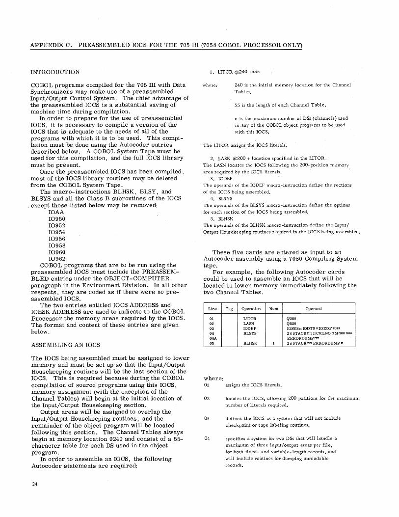
APPENDIX C. PREASSEMBLED IOCS FOR THE 705 III (7058 COBOL PROCESSOR ONLy)
INTRODUCTION
COBOL programs compiled for the 705 III with Data Synchronizers may make use of a preassembled Input/Output Control System. The chief advantage of the preas sembled IOCS is a substantial saving of machine time during compilation.
In order to prepare for the use of preassembled IOCS, it is necessary to compile a version of the IOCS that is adequate to the needs of all of the programs with which it is to be used. This compilation must be done using the Autocoder entries described below. A COBOL System Tape must be used for this compilation, and the full IOCS library must be present.
Once the preas sembled IOCS has been compiled, most of the IOCS library routines may be deleted from the COBOL System Tape.
The macro-instructions BLHSK, BLSY, and BLSYS and all the Class B subroutines of the IOCS
, except those listed below may be removed: IOAA 10950 10952 10954 10956 10958 10960 10962
COBOL programs that are to be run using the preassembled IOCS must include the PREASSEMBLED entries under the OBJECT-COMPUTER paragraph in the Environment Division. In all other respects, they are coded as if there were no preassembled IOCS.
The two entries entitled IOCS ADDRESS and IOHSK ADDRESS are used to indicate to the COBOL Processor the memory areas required by the IOCS. The format and content of these entries are given below.
ASSEMBLING AN IOCS
The IOCS being assembled must be assigned to lower memory and must be set up so that the Input/Output Housekeeping routines will be the last section of the IOCS. This is required because during the COBOL compilation of source programs using this IOCS, memory assignment (with the exception of the Channel Tables) will begin at the initial location of the Input/Output Housekeeping section.
Output areas will be assigned to overlap the Input/Output Housekeeping routines, and the remainder of the object program will be located following this section. The Channel Tables always begin at memory location 0240 and consist of a 55-character table for each DS used in the object program.
In order to assemble an IOCS, the following Autocoder statements are required:
24
1. LITOR @l240 +55n
where: 240 is the initial memory location for the Channel
Tables.
55 is the length of each Channel Table.
n is the ,maximum number of DSs (channels) used
in any of the COBOL object programs to be used
with this IOCS.
The LITOR assigns the IOCS literals.
2. LASN @l200 + location specified in the LITOR.
The LASN locates the IOCS following the 200-position memory
area required by the IOCS literals.
3. IODEF
The operands of the IODEF macro-instruction define the sections
of the IOCS being assembled.
4. BLSYS
The operands of the BLSYS macro-instruction define the options
for each section of the IOCS being assembled.
5. BLHSK
The operands of the BLHSK macro-instruction define the Input/
Output Housekeeping routines required in the IOCS being assembled.
These five cards are entered as input to an Autocoder assembly using a 7080 Compiling System tape.
For example, the following Autocoder cards could be used to assemble an IOCS that will be located in lower memory immediately following the two Channel Tables.
Line Tag Operation Num Operand
01 LITOR @350 02 LASN @550 03 IOOEF IOSYSJ:I lOOTS OIOEOF = 04 BLSYS 2J:1STACKJ:l3J:1CKLNGJ:lM== 04A ERRORDUMPt:a:I 05 BLHSK 1 2 J:I ST ACK t:a:I ERRORDUMP J:I
where: 01 assigns the IOCS literals.
02 locates the IOCS, allowing 200 positions for the maximum
number of literals required.
03 defines the IOCS as a system that will not include
checkpoint or tape labeling routines.
04 specifies a system for two DSs that will handle a
maximum of three input/output areas per file,
for both fixed- and variable-length records, and
will include routines for dumping unreadable
records.
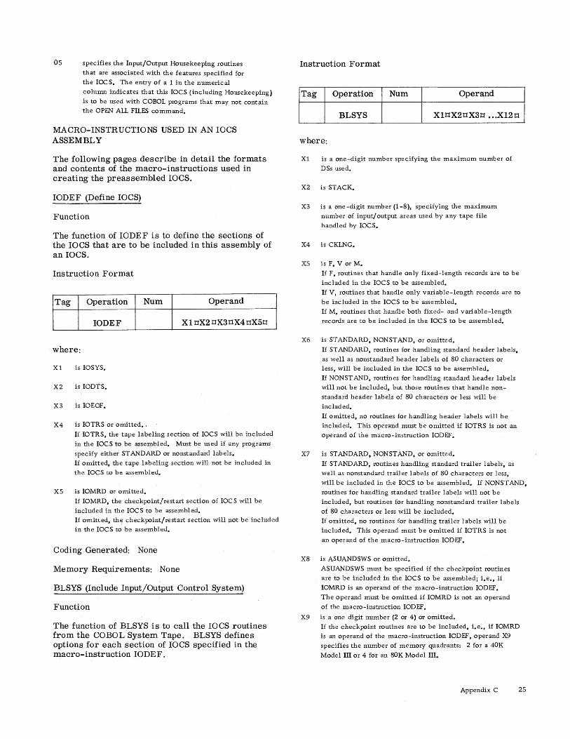
05 specifies the Input/Output Housekeeping routines
that are associated with the features specified for
the IOCS. The entry of a 1 in the numerical
column indicates that this IOCS (including Housekeeping)
is to be used with COBOL programs that may not contain
the OPEN ALL FILES command.
MACRO-INSTRUCTIONS USED IN AN laCS ASSEMBLY
The following pages describe in detail the formats and contents of the macro-instructions used in creating the preassembled IOCS.
IODEF (Define IOCS)
Function
The function of IODEF is to define the sections of the IOCS that are to be included in this assembly of an IOCS.
Instruction Format
Tag Operation Num Operand
IODEF Xl IlX2 IlX3tlX4 tlX5Il
Instruction Format
Tag Operation Num Operand
BLSYS XltlX2IlX3Il ••. XI2 tl
where:
Xl is a one-digit number specifying the maximum number of
DSs used.
X2 is STACK.
X3 is a one-digit number (1-8), specifying the maximum
number of input/ output areas used by any tape file
handled by IOCS.
X4 is CKLNG.
XS is F, V or M.
If F, routines that handle only fixed-length records are to be
included in the IOCS to be assembled.
If V, routines that handle only variable-length records are to
be included in the IOCS to be assembled.
If M, routines that handle both fixed- and variable-length
records are to be included in the IOCS to be assembled.
X6 is STANDARD. NONSTAND, or omitted.
where: If STANDARD, routines for handling standard header labels,
as well as nonstandard header labels of 80 characters or Xl
X2
X3
X4
is IOSYS.
is IODTS.
is IOEOF.
is IOTRS or omitted •.
If IOTRS, the tape labeling section of IOCS will be included
in the IOCS to be assembled. Must be used if any programs
specify either STANDARD or nonstandard labels.
If omitted, the tape labeling section will not be included in
the IOCS to be assembled.
X5 is IOMRD or omitted.
If IOMRD. the checkpoint/restart section of IOC S will be
included in the IOCS to be assembled.
If omitted. the checkpoint/restart section will p.ot be included
in the IOCS to be assembled.
Coding Generated: None
Memory Requirements: None
BLSYS (Include Input/Output Control System)
Function
The function of BLSYS is to call the IOCS routines from the COBOL System Tape. BLSYS defines options for each section of IOCS specified in the macro-instruction IODEF.
less, will be included in the IOCS to be assembled.
If NONST AND, routines for handling standard header labels
will not be included, but those routines that handle non
standard header labels of 80 characters or less will be
included.
If omitted, no routines for handling header labels will be
included. This operand must be omitted if IOTRS is not an
operand of the macro-instruction IODEF.
X7 is STANDARD. NONSTAND. or omitted.
If STANDARD, routines handling standard trailer labels, as
well as nonstandard trailer labels of 80 characters or less,
will be included in the IOCS to be assembled. If NONST AND.
routines for handling standard trailer labels will not be
included, but routines for handling nonstandard trailer labels
of 80 characters or less will be included.
If omitted, no routines for handling trailer labels will be
included. This operand must be omitted if IOTRS is not
an operand of the macro-instruction IODEF.
X8 is ASUANDSWS or omitted.
ASUANDSWS must be specified if the checkpoint routines
are to be included in the IOCS to be assembled; i.e., if
IOMRD is an operand of the macro-instruction IODEF.
The operand must be omitted if IOMRD is not an operand
of the macro-instruction IODEF.
X9 is a one digit number (2 or 4) or omitted.
If the checkpoint routines are to be included, i.e., if IOMRD
is an operand of the macro-instruction IODEF, operand X9
specifies the number of memory quadrants: 2 for a 40K
Model III or 4 for an 80K Model III.
Appendix C 25

This operand must be omitted if IOMRD is not an operand of
the macro-instruction IODEF.
Xl0 is omitted.
Xll is ERRORDUMP.
Routines associated with the dumping of unreadable records
will be included in the IOCS to be assembled.
X 12 is omitted (single lozenge required).
Note: The routines described in the above operan:ds can be included in the IOCS assembly, if desired, even if a given object program does not use all of the features.
Coding Generated
Tag Operation Num Operand
INCL IOaaa
INCL IObbb NAME 0 RCD 0
BLSYS xxxxx
where: aaa and bbb are the first and last IOCS subroutines to be
included.
xxxxx is the number of memory positions used by IOCS.
Memory Requirements
The memory requirements are those specified by xxxxx under BLSYS "Coding Generated. "
BLHSK (Include Input/Output Housekeeping Section of lOCS)
Function
The function of BLHSK is to call the Input/Output Housekeeping routines from the COBOL System Tape.
Instruction Format
Tag Operation Num Operand
BLHSK Xl X2oX30X4oX50
where: Xl is 1.
26
1 must be specified in the numeric columns since ~ of
the COBOL ob ject programs to be used with the IOCS being
assembled may contain the command OPEN ALL FILES.
X2 is a one -digit number specifying the total number of DSs
used. Operand X 1 in the macro-instruction BLSYS should
specify the same one-digit number.
X3 is STACK.
X4 is STANDARD or omitted.
XS
If STANDARD, routines associated with the handling of
standard header labels will be included in the Input/Output
Housekeeping to be assembled. Operand X6 in the macro
instruction BLSYS should also specify STANDARD.
If omitted, routines associated with the handling of
standard header labels will not be included. Operand X6
in the macro-instruction BLSYS should be omitted or
specify NONST AND.
is ERRORDUMP.
Routines associated with the dumping of unreadable
tecords will be included in the Input/Output Housekeeping
to be assembled. OpEi!rand X11 in the macro-instruction
BLSYS should also specify ERRORDUMP.
Note: The routines described in the above operands can be included in the Input/Output Housekeeping assembly, if desired, even if a given object program does not use all of the features.
Coding Generated
Tag
BLHSK
where: aaa and bbb
xxxxx
Operation Num Operand
INCL IOaaa
INCL IObbb NAME 0
RCD 0 xxxxx
are the first and last IOHSK subroutines to be
included.
is the number of memory positions used by IOHSK.
Memory Requirements
The memory requirements are those specified by xxxxx under BLHSK "Coding Generated. "
ASSEMBLING AN OBJECT PROGRAM TO BE USED WITH A PREASSEMBLED IOCS
The COBOL source program to be used with a preassembled IOCS must include the IOCS ADDRESS and IOHSK ADDRESS entries under the OBJECTCOMPUTER paragraph of the Environment Division.
The IOCS ADDRESS entry specifies, in five-digit form, the initial and final memory locations of the IOCS, excluding the literals and the Input/Output Housekeeping section. These locations may be obtained from the preas sembled IOCS listing beneath

the coding generated for the macro-instruction BLSYS. The initial location is specified in the NAME entry and the final location in the ReD entry tagged BLSYS.
The IOHSK ADDRESS entry specifies, in fivedigit form, the initial and final memory locations of the Input/Output Housekeeping section. These locations may be obtained from the preassembled IOCS listing beneath the coding generated for the macro-instruction BLHSK. The initial location is specified in the NAME entry and the final location, in the RCD entry tagged BLHSK.
In all other respects, the source program must be set up in the manner described in this publication and in the COBOL general information publication.
The source program compilation is a normal COBOL compilation.
INCLUSION OF THE 705 III PREASSEMBLED IOCS WITH THE OBJECT PROGRAM
After the source program has been compiled, the program cards should be combined with the preassembled lOCS program deck as follows:
1. Load program (or object program load card) 2. Preassembled IOCS 3. Object program 4. Object program "00" card The "00" card and load card of the preassembled
IOCS should be discarded. The object program load card must be discarded if an alternate load program is used.
Appendix C 27

APPENDIX D.PREASSEMBLED IOCSFOR THE 7080
INTRODUCTION
The 7058 COBOL Processor cannot generate a 7080 Input/Output Control System. Therefore, a preassembled' 7080 10CS must be incorporated into object programs compiled by this processor. The 7080 COBOL Processor is capable of generating a 7080 IOCS as part of a normal compilation. However, a preassembled IOCS is also acceptable. The chief advantage to be derived from the preas sembled 10CS is a substantial saving of machine time during compilation.
In order to prepare for the use of the preasserrlbled IOCS, it is necessary to compile a version of the IOCS that is adequate to the needs of all of the programs with which it is to be used. Once this has been done, COBOL programs that are to be run using the preassembled IOCS must include the PREASSEMBLED entries under the OBJECT-COMPUTER paragraph in the Environment Division. In all other respects, they are coded as if there were no preassembled IOCS.
The entries IOCS ADDRESS and IOHSK ADDRESS are used to indicate to the 7080 COBOL Processor the memory areas required by the IOCS. The formats and contents of these entries are given below.
ASSEMBLING AN IOCS
The IOCS being assembled must begin at memory location 0500 and must be set up so that the Input/ Output Housekeeping routines will be the last section of the IOCS. This is required because, during the COBOL compilation of source programs using this IOCS, memory aSSignment will begin at the initial location of the Input/Output Housekeeping section.
Output areas will be assigned to overlap the Input/Output Housekeeping routines, and the remainder of the object program will be located following this section. The Tape Tables always begin at memory location 0500.
Full details of specifying the 10CS to be assembled are given in the following publications:
28
IBM 7080 Input/Output Control System for Use with 729 MagnetiC Tape Units, Form C28-6237
IBM 7080 Input/Output Control System for 7340 Hypertape Drives -- #7080-10-932, Form C28-6341
ASSEMBLING AN OBJECT PROGRAM TO BE USED WITH A·· PREASSElVIBLED IOCS
The COBOL source program to be used with a preassembled 10CS must include the IOCS ADDRESS and 10HSK ADDRESS clauses (for 729 files) and/or the HYPERTAPE-IOCS ADDRESS clause (for Hypertape files) under the OBJECT-COMPUTER paragraph of the Environment Division.
The IOCS ADDRESS clause specifies, in fivedigit form, the initial memory location of the IOCS, excluding the Input/Output Housekeeping section. This location should be 00500.
The HYPERTAPE-IOCS ADDRESS clause specifies, in five-digit form, the initial location of the Hypertape IOCS. This location can be obtained from the preas sembled IOCS listing by referring to the Autocoder tag CSHYOPLBL.
The IOHSK ADDRESS clause specifies, in fivedigit form, the initial and final memory locations of the Input/Output Housekeeping section. These locations may be obtained from the preassembled IOCS listing by referring to the Autocoder tag CSA028005 and the highest memory location used by IOCS.
In all other respects, the source program must be set up in the manner described in this publication and in the COBOL general information publication.
INCLUSION OF THE 7080 PREASSEMBLED 10CS WITH THE OBJECT PROGRAM
Following the compilation of the COBOL object program, the program cards should be combined with the preas sembled 7080 IOCS in the following order:
1. Load program 2. Preas sembled IOCS 3. Object program 4. Object program "00" transfer control card
The "00" card and load program of the preas sembled IOCS should be discarded.
Note: The object program load cards must be discarded if an alternate load program is used.
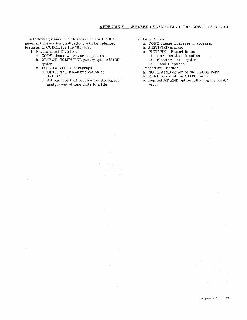
APPENDIX E. DEFERRED ELEMENTS OF THE COBOL LANGUAGE
The following items, which appear in the COBOL general information publication, will be deferred features of COBOL for the 705/7080:
1. Environment Division. a. COpy clause wherever it appears. b. OBJECT-COMPUTER paragraph: ASSIGN
option. c. FILE-CONTROL paragraph.
i. OPTIONAL file-name option of SELECT.
ii. All features that provide for Processor assignment of tape units to a file.
2. Data Division. a. COPY clause wherever it appears. b. JUSTIFIED clause. c. PICTURE - Report Items.
i. + or - on the left option. ii. Floating + or - option.
iii. 0 and B options. 3. Procedure Division.
a. NO REWIND option of the CLOSE verb. b. REEL option of the CLOSE verb. c. Implied AT END option following the READ
verb.
Appendix E 29

APPENDIX F. COMPLETE LIST OF COBOL RESERVED WORDS
The words bisted below are an inherent part of the COBOL System. Their use as data or procedure names should be avoided. The list includes all words that have special meaning as either key words or optional words for any IBM COBOL Compiler.
ABOUT
ACCEPT ADD ADDITIONAL-LABEL-INFO
ADDRESS
ADDRESSES ADVANCING AFTER
ALL ALL-FILES
ALPHABETIC ALPHANUMERIC
ALTER ALTERATION -SWITCH
ALTER-LABEL-INFO
ALTERNATE
AL TERNATE-10-RETURN ALT-SWITCH-n AN
AND APPLY ARE
AREA AREAS
AS ASCENDING ASSEMBLY -PROGRAM
ASSIGN AT
AUTHOR
AUTHORS
AUTOCODER AUTOLOADER
BCD BEFORE
BEGINNING
BEGINNING-FILE-LABEL
BEGINNING -HYPER T APE- LABEL
BEGINNING -REEL BEGINNING-TAPE-LABEL
BINARY
BIT
BITS
BLANK
BLOCK BLOCKS BLOCK-COUNT
BLOCK-OR-CHECKSUM-ERROR
BLOCK- SEQUENCE-ERROR
BUFFER -OVERFLOW BY CALL
CARD-PUNCH
CARD-READER
30
CARDS
CF CH CHARACTER
CHARACTERS
CHECK
CHECKPOINT CHECKPOINT - UNIT
CHECKSUM CHECKSUM-ERROR
CLASS
CLOCK-UNITS
CLOSE
COBOL [-xxxxJ CODE
COLLATE-COMMERCIAL COLLA TE-MACHINE COLUMN
COMMUNICA nON -MODE
COMPUTATIONAL
COMPUT ATIONAL-l COMPUT ATIONAL-2 COMPUTE
CONFIGURATION CONSOLE-PRINTER CONSOLE-SWITCH
CONSTANT
CONTAIN CONTAINS CONTROL
CONTROL-COUNT -ERROR CONTROLS
COPY
CORRESPONDING CREATION-DATE
CREATION-DAY
CREATION - YEAR DATA
DATE-COMPILED
DA TE-WRITTEN DE
DEC LARA TlVES DEFINE
DENSITY DEPENDING
DESCENDING DETAIL
DIGIT
DIGITS DISPLAY
DIVIDE DIVIDED
DIVISION DOLLAR
DOUBLE-PRECISION
ELECTRONIC-SWITCH
ELIMINATION ELSE EL-SWITCH-n END
ENDING

ENDING-FILE
ENDING-FILE-LABEL
ENDING-HYPERTAPE-LABEL
ENDING-REEL ENDING-TAPE-LABEL END-OF -FILE
END-OF -REEL
END-OF -TAPE
ENTER
ENVIRONMENT EOF-SIU EQUAL
EQUALS
ERROR ERROR-CONDITION ERROR-DUMP ERROR-FILE-ADDRESS
ERROR-RECORD
EVEN EVERY
EXAMINE
EXCEEDS EXIT EXPONENTIATED
FD
FILE
FILE-CONTROL FILE-IDENTIFICA nON
FILE-PROTECT FILE-REFERENCE
FILE-SERIAL-NUMBER FILES
FILLER
FILLING FINAL
FIRST FLOAT
FLOA TING -POINT -HARDWARE FOOTIN"G
FOR
FORMAT
FROM
GENERATE
GIVING GO GREATER
GROUP HASHED
HEADER HEADER -LABEL
HEADIN"G
HIGH
HIGH-VALUE
HIGH-VALUES
HYPERTAPE-IOCS HYPERT APE- UNIT
HYPER T APE- UNITS
IBM-1401
IBM-1410 IBM-1460 IBM-70S-1
IBM-70S-2 IBM-70S-3
IBM-7010
IBM-7040
IBM-7044 IBM-7070
IBM-7072
IBM-7074 IBM-7080
IBM-7090
IBM-7094 I-O-CONTROL
I-O-SWITCH
ID IDENTIFICA TION
IF
IN INCLUDE INCOMPLET E-WORD-ERROR
INDEX-WORD-n INDICATE
INITIATE
INPUT INPUT -OUTPUT
INST ALLA TION INTERCHANGEABLE
INTO INV ALID-CHARACTER-CHECK
IOCS
IOHSK
IORETURN IORTN1
IORTN2 IS
JUSTIFIED KEY KEY-S KEY-1
KEY-3S
LABEL LABEL-DATA
LABEL-IDENTIFIER
LABEL-RECORDS
LAST
LEADING
LEAVING LEFT
LESS
LIBRARY
LIMIT LIMITS LINE
LINE-COUNTER
LIN"ES
LIN"KAGE-MODE
LOAD
LOCATION LOCK
LONG-LENGTH-RECORD
LOW LOW-VALUE LOW-VALUES LOWER-BOUND
LOWER-BOUNDS
MEMORY MEMORY-DUMP MEMORY -DUMP-KEY
Appendix F 31

MINUS MIXED-MODE-ERROR
MODE MODULES MONITOR-DATE MONITOR-SWITCH
MOVE MULTIPLE MULTIPLIED
MULTIPLY NEGATIVE
NEXT
NO NO-LENGTH-CHECK NO-MEMORY -DUMP
NONE NON -ST ANDARD
NO-OVERLAP NO-PRINT -STORAGE
NO-RELEASE NO- T APEMARK NO- TAPE-MARK NORMAL-10-RETURN
NOT NOTE
NUMBER
NUMERIC OBJECT -COMPUTER
OBJECT -PROG RAM OCCURS
ODD
OF
OFF
OH
OMITTED
ON
OPEN OPEN - WITHOUT -REWIND
OPTIONAL
OPTIONAL-USAGE
OR
OTHERWISE
OUTPUT
OUTPUT-FILES
OV
OVERFLOW OVERLAP-FILE-AREA
PACKED
PADDING PAGE
- PAGE-COUNTER
PARITY PERFORM
PERMANENT - WRITE-ERROR
PF PH
PICTURE
PLACE
PLACES
PLUS POINT
POSITION
POSITIVE PREASSEMBLED
32
PREPARED
PRINTER PRINTER-720
PRIORITY PROCEDURE
PROCEED PROGRAM-ID
PROGRAM-START
PROTECT
PROTECTION
PUNCH PURGE-CYCLE
PURGE-DATE
QUOTE
QUOTES
RANGE RD READ READER
RECORD RECORD-COUNT
RECORDING RECORD-MARK
RECORDS
REDEFINES REDUNDANCY -ERROR
REEL REEL-NUMBER
REELS REEL- SEQUENCE-NUMBER
REEL- SERIAL-NUMBER
REFERENCE
RELEASE REMARKS
REMEMBER
RENAMES
RENAMING REPLACING
REPORT REPORTING
REPORTS
RERUN RERUN-RECORDS
RERUN-WORK RESERVE
RESET
RESTART RETENTION -CYCLE
RETENTION -PERIOD
RETURN REVERSED
REWIND
RF
RH RIGHT ROUNDED
RUN SAME
SD SECTION SECURITY SEGMENT - LIMIT
SELECT SELECTED

SENSE- SWITCH-1-6
SENTENCE
SENTINEL
SEQUENCE-CHECK
SEQUENCED
SHORT-ALPHA-WORD
SHORT -LENGTH-RECORD
SIGN
SIGNED
SIZE
SORT
SOURCE
SOURCE-COMPUTER
SPACE
SPACES SPECIAL-NAMES
STANDARD
ST ANDARD-LABEL
STATUS STOP
SUBTRACT
SUM
SUPERVISOR
SUPPRESS
SYNCHRONIZED
SYNCH-N
SYSTEM-INPUT - UNIT
SYSTEM-OUTPUT -PRINTER
SYSTEM-OUTPUT-PUNCH
SYSTEM-OUTPUT - UNIT
TALLY
TALLYING TAPE
TAPES
TAPE-UNIT
TAPE-UNITS
T APE-WITH- LABELS
TAPE-WITHOUT-LABELS
TERMINATE
TEST -P AT TERN
THAN
THEN
THROUGH
THRU
TIME
TIMES TO
TRAILER -LABEL
TYPE TYPEWRITER
UNEQUAL
UNIT -RECORD-I-O-RECORD
UNOPENED-FILE
UNPACKED
UNTIL
UPON
UPPER-BOUND
UPPER-BOUNDS
USAGE
USE
USING
VALUE
VALUES
VARYING
WHEN
WITH
WITH-LABELS WITHOUT -LABELS
WORDS
WORKING-STORAGE
WRITE
ZERO
ZEROES
ZEROS
1401-SS
1402-P
1402-R
1403-CT
1403-P
1403-P-CB
1403-P-CV
1403-P-C9
705-1
705-2
705-3
729-m
7080
Appendix F 33

APPENDIX G. ADDITIONAL CONSIDERATIONS
.RESTRICTIONS ON THE USE OF THE COBOL LANGUAGE
The implied AT END with READ statement is disallowed on the 7080 COBOL Processor.
The format of a READ statement is:
READ file-name AT END any imperative statement
Each READ statement must have an explicit AT END. If no AT END is specified by the programmer, the Processor will create an ending routine, consisting of a loop, for that particular READ statement.
LANGUAGE INCOMPATIBILITY
If the COBOL program is to be compiled for more than one computer, the following verbs and clauses should be avoided as much as possible since their definitions may' not be compatible in all systems.
I
34
Verbs
The following COBOL verbs and their associated language specifications cannot be defined in compatible terms in any two systems.
1. ACCEPT 2. UPON option of the DISPLAY verb 3. ENTER 4. USE
Clauses
The three editing clauses, ZERO SUPPRESS, CHECK PROTECT, and FLOAT DOLLAR SIGN are redundant, since the PICTURE clause can be used for all their functions. In addition, certain errors in their specification, resulting in conflicting requirements, make implementation difficult. It is therefore recommended that PICTURE be used whenever editing of this kind is required.
Special Characters
The 7058 and 7080 COBOL Processors permit alphanumeric literals to contain any character in the computer's character set. However, only the COBOL character set will insure complete compatibility with other IBM systems.

ACCEPT 8,11
ADD 2, 19
ADDRESS 8
ALPHABE TIC 15, 17
ALPHANUMERIC 15, 17
Alphanumeric literals 6
AN 15 Analysis run 6
APPLY 11
Assembling an IOCS: For the 705 III 24
For the 7080 28
ASSIGN 10, 11
ASU settings 18
ASUSAVE 23
AT END 2, 17, 29, 34
Autocoder tags
AUTOLOADER
7,9, 18
10, 11, 12
BEGINNING-HYPER TAPE-LABEL 14, 20
BEGINNING-REEL 11, 21, 22
BEGINNING-TAPE-LABEL 14, 20
BLASU06 18 BLASU12 18
BLHSK 24, ~
BLIXT 2,.ll
BLOCK 1O,ll BLSY 24
BLSYS 24, 22..
CASU settings 21
Channel tables 8,24
Character set 7
CHARACTERS 8,~
Checking:
of labels 9, 20
of record count 20
of record length 23
of reels 9, 20
CHECKPOINT 13
Checkpoint taking 9, 11, 12, 13, 23
CLASS 15
Class B subroutines 24
CLOSE 12, 17, 18, 29
Compilation listing 6
Compilation run 6
Conditional statements 17
Condition-names 7
Configuration Section 7
Control cards 20 CORRESPONDING 2, 19
DATA RECORD 10
Date 7 Date control card 20
DA TE-COMPILED 7
Deblocking 9
Decimal point 15
Deferred features 29
Device name formats 7
Diagnostic messages 6 \
DISPLAY 8, 15, 1&
ELSE 17
End control card 20
END OF RUN message 19
ENDING-FILE 11, 20
ENDING-HYPERTAPE-LABEL 14, 20
ENDING-REEL 12, 20
ENDING-TAPE-LABEL 14, 20
ENTER 18
ENTER AUTOCODER 9, 21
Environment Division 7
ERROR 17, 19
Error Checking 20
ERROR-DUMP 10
FILE-CONTROL 9
File Description entries 13
FIlE-PROTECT 12 File Serial Header control card 20
Format of device names 7
Format of input and output 12
FROM 17
GO TO 11, 18
Hash totals 23
Header labels 9, 14
HIGH 13
HIGH-VALUE 7
Hyperta pe capabilities 2, 5
Identification Division 7
IF 17
Incompatibility 34
INITIATE mode 23 Input/Output section 9
Input reel checking 9
INTERCHANGEABLE 13
I-O-CONTROL 11
IOCS use 23
IODEF 24,~
Label control cards 20
LABEL-DATA 11
Labels 9, 13, 20
LASN 24
LEFT 14 Limitations on verb formats 17
Listing, from compilation 6
Literals 7
LIT OR 24
NOTE: Underscored numbers indicate the principal reference.
LOCK 18
LOW 13
LOW-VALUE 7
Mac ro- instructions:
BLHSK 24, 26
BLIXT 21
BLSY 24
BLSYS 23, 24
IODEF 24
MEMORY 8
Messages, diagnostic
Mnemonic name 8
MOVE 15
M UL TIPLE REEL 10
NO 10 NO-LENGTH-CHECK
N 0-T APEMARK 14
NUMERIC 15, 17
Numeric items 15
Numeric literals 6
INDEX
6
13
OBJECT-COMPUTER ~ 13, 17, 24
OCCURS 17
OMITTED 14
ON SIZE ERROR 17
OPEN 17. 18, 23
OTHERWISE 17
Output reel checking 9
PACKED
PERFORM
PICTURE
13
11, 18
14
PREASSEMBLED 8, 24, 26,
Preassembled IOCS 24, 26
Procedure Division 17
PROGRAM-ID 7
PROGRAM-START 9
Q UALIFICA TION 17
READ 17, 23, 29, 34
RECORD 10, 1~
Record blocking 9
Record counts 12, 20
Record Description entries 14
Record length checking 23
RECORDING 13
REDEFINES
RENAMING Report items
RERUN 12
16
.!Q, 17 15
RERUN-WORK 11
RESERVE 10
Index 35

J28-6177 -3
Reserved words 30
RESTART 11
Restrictions 34
RIGHT 14
ROUNDED 19
RUN 19
SELECT 10
SIZE 16, 17, 19
Size errors 17
SOURCE-COMPUTER 7
International Business Machines Corporation Data Processing Division 112 East Post Road, White Plains, N. Y. 10601
SPECIAL-NAMES
STACKING mode
STANDARD 14
STOP 19
8, 17
23
SYNCHRONIZED 14
SUBTRACT 2, 19
Tape Reel Control System 9
Tape unit assignment 10
Trailer labels 9, 14
UNPACKED 13
UPON 17, 18
USAGE 15
V label option 23
VALUE 16
WRITE 18
ZERO 7