systems analysis and design. plan introduction structured methods –data flow modelling –data...
Post on 21-Dec-2015
222 views
TRANSCRIPT
Systems Analysis and Design
Plan
• Introduction
• Structured Methods– Data Flow Modelling
– Data Modelling
– Relational Data Analysis
• Feasibility
• Maintenance
Plan
• Introduction
• Structured Methods– Data Flow Modelling
– Data Modelling
– Relational Data Analysis
• Feasibility
• Maintenance
Data Flow Modelling
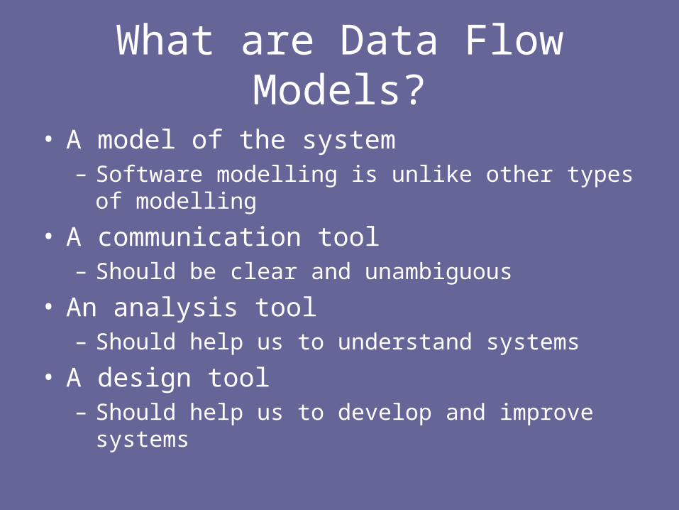
What are Data Flow Models?
• A model of the system– Software modelling is unlike other types of modelling
• A communication tool– Should be clear and unambiguous
• An analysis tool– Should help us to understand systems
• A design tool– Should help us to develop and improve systems
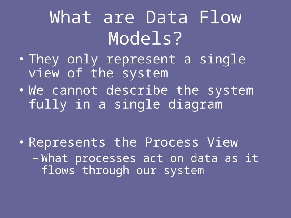
What are Data Flow Models?
• They only represent a single view of the system
• We cannot describe the system fully in a single diagram
• Represents the Process View– What processes act on data as it flows
through our system
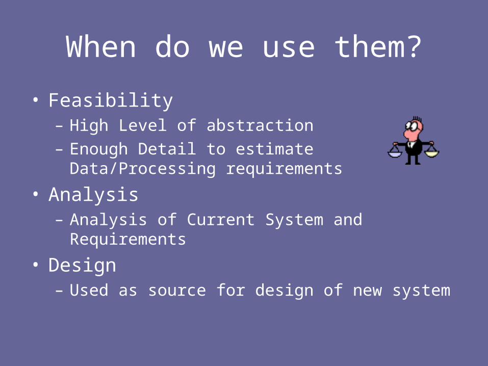
When do we use them?
• Feasibility– High Level of abstraction– Enough Detail to estimate Data/Processing
requirements
• Analysis– Analysis of Current System and Requirements
• Design– Used as source for design of new system

Structured Analysis + Design
Existing System ERD
Repository
Existing Physical
System DFD
New System ERD
Repository
New Logical System DFD
Convert to Logical View
User Requirements
Technical Options +
Constraints
New Physical System
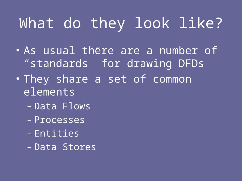
What do they look like?
• As usual there are a number of “standards” for drawing DFDs
• They share a set of common elements– Data Flows– Processes– Entities– Data Stores
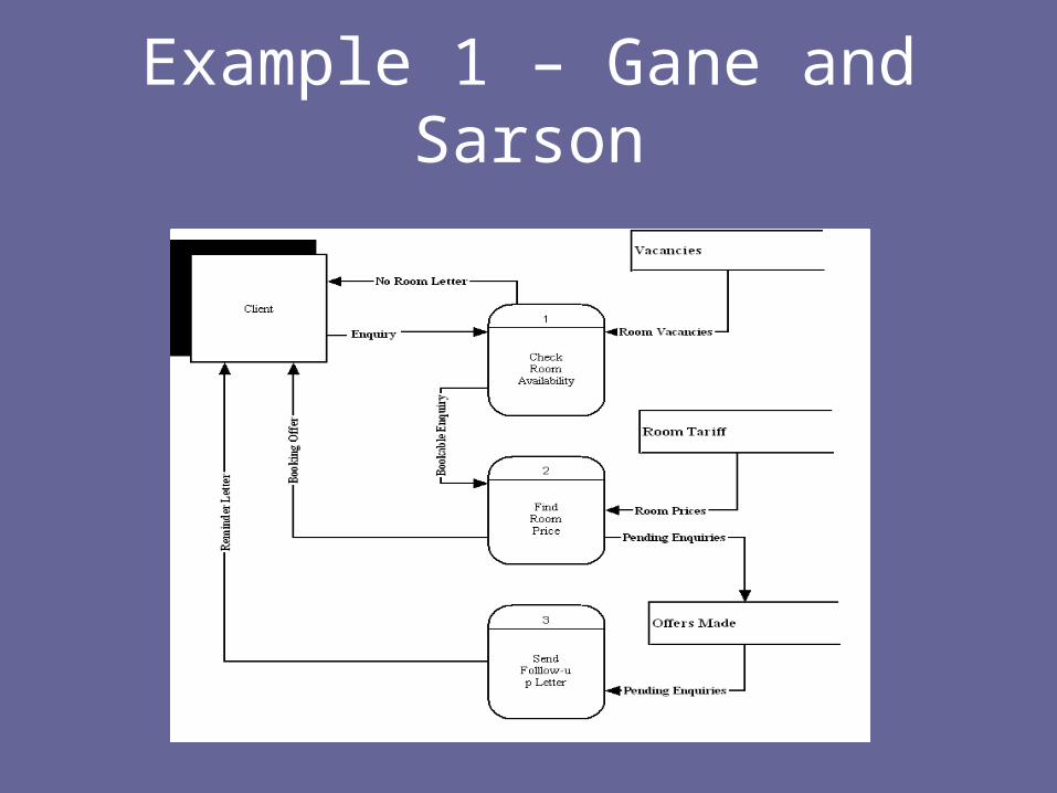
Example 1 – Gane and Sarson
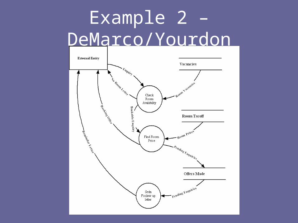
Example 2 – DeMarco/Yourdon
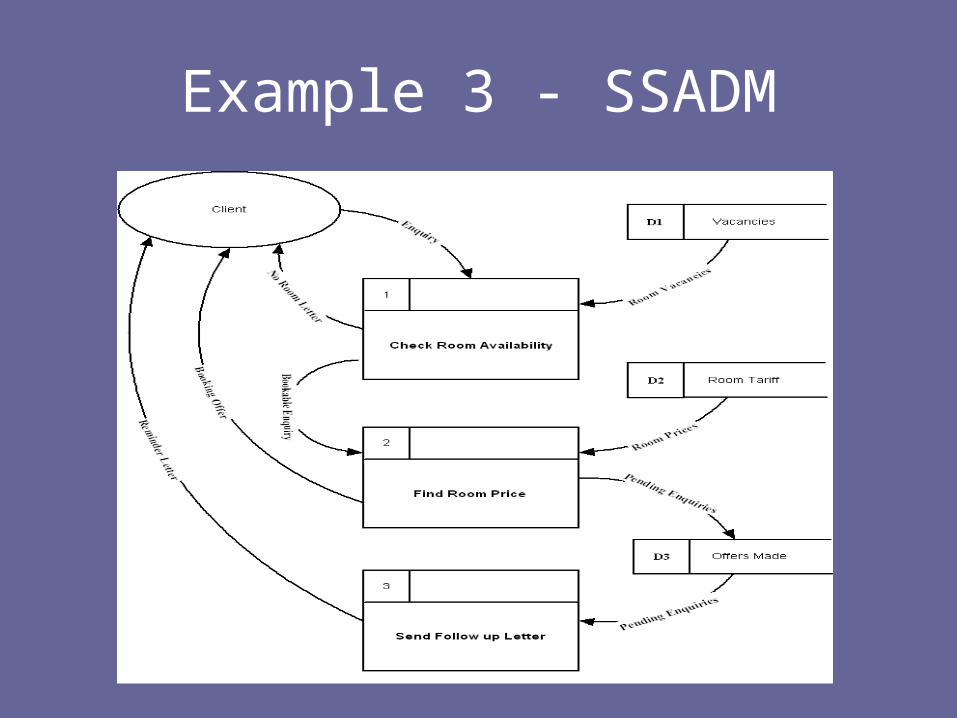
Example 3 - SSADM
What do they look like?
• We will use the SSADM style
• Used in Lejk and Deeks, 2002
• You should be able to read diagrams using another style
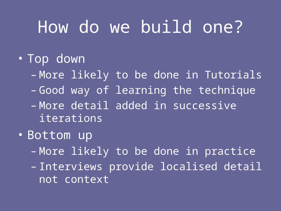
How do we build one?
• Top down– More likely to be done in Tutorials– Good way of learning the technique– More detail added in successive iterations
• Bottom up– More likely to be done in practice– Interviews provide localised detail not context

Building a Data Flow Model
• Understand the system• Establish the context• Identify major processes• Identify Data Flows:
– What do processes produce as output– What Data is required to produce output
• Identify other elements– Where does data come from/go to
• Check against System Description
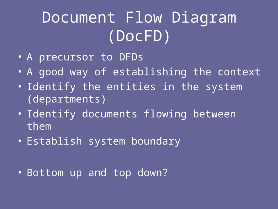
Document Flow Diagram (DocFD)
• A precursor to DFDs• A good way of establishing the context• Identify the entities in the system (departments)• Identify documents flowing between them• Establish system boundary
• Bottom up and top down?
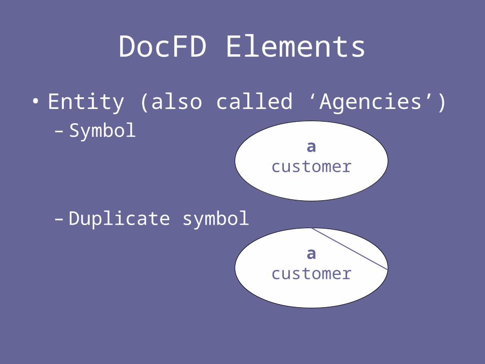
DocFD Elements
• Entity (also called ‘Agencies’)– Symbol
– Duplicate symbol
acustomer
acustomer
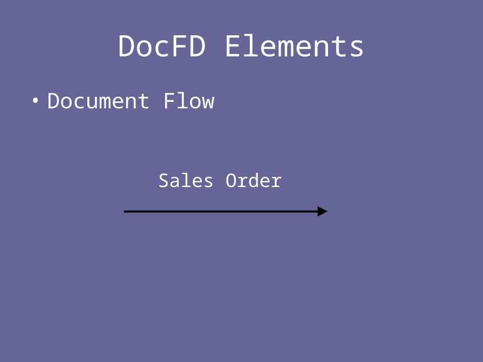
DocFD Elements
• Document Flow
Sales Order

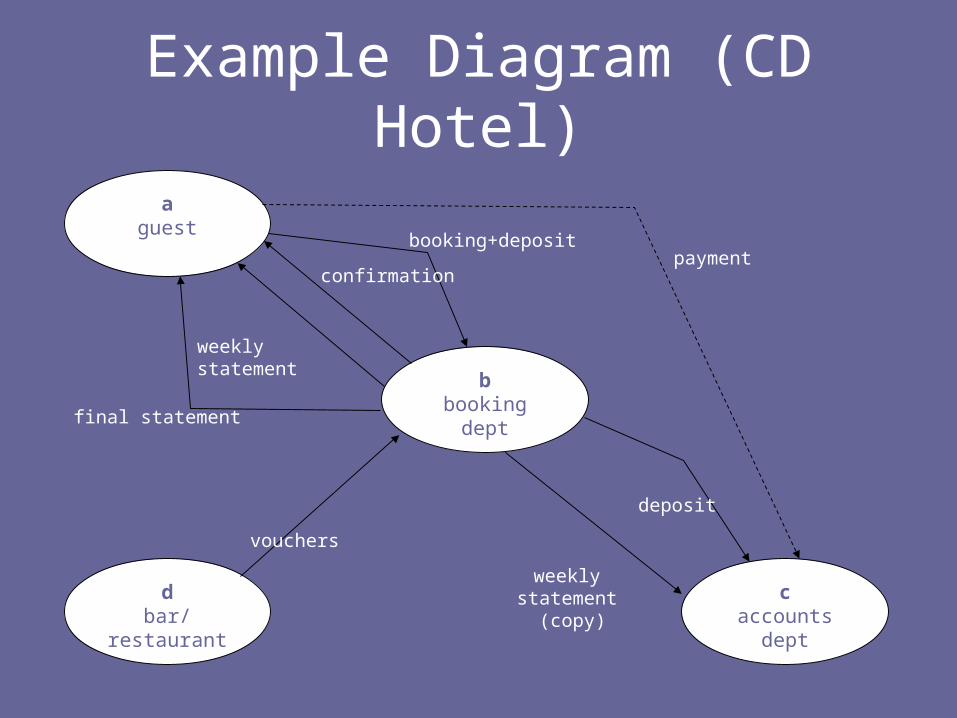
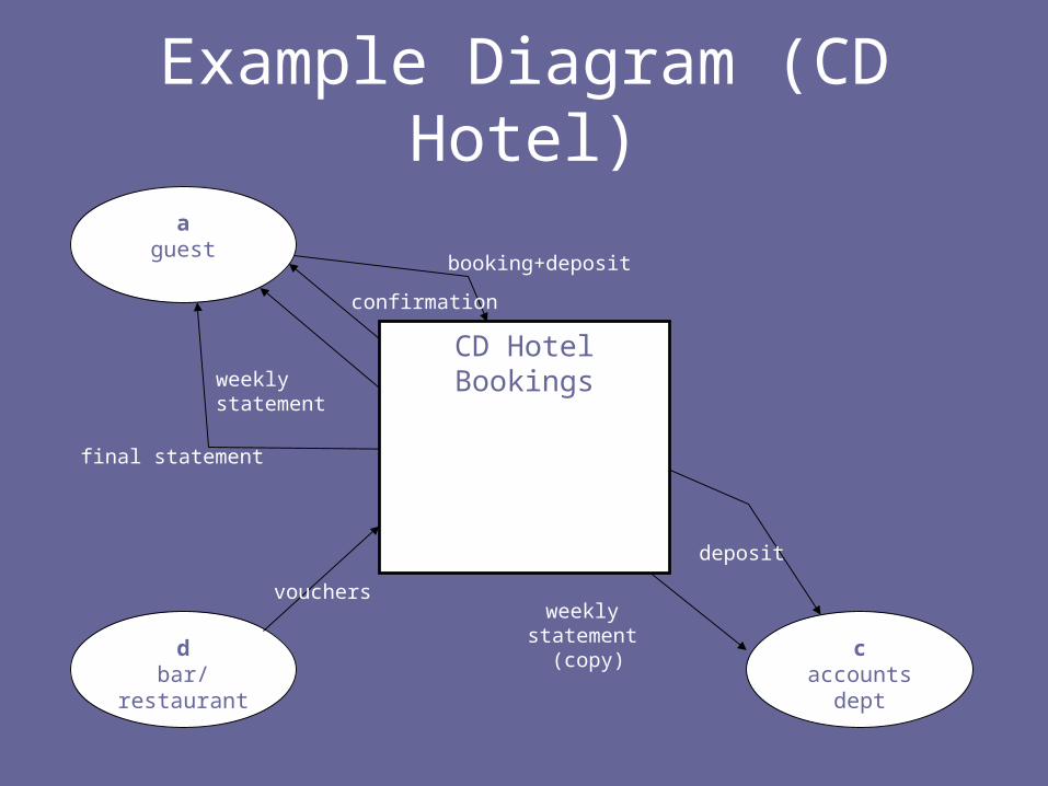
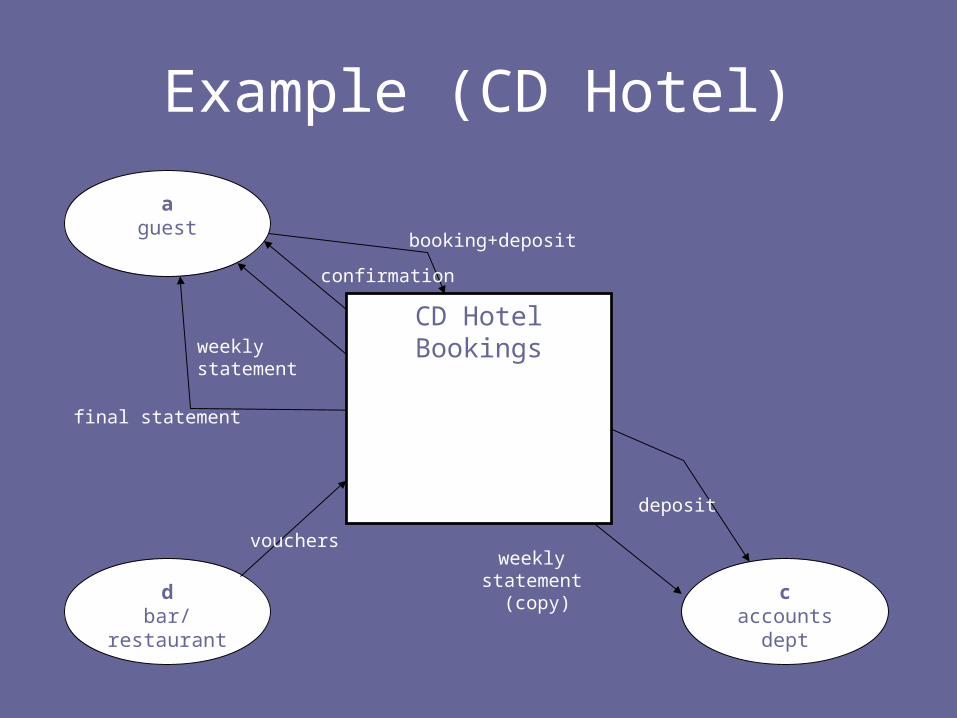
Example Diagram (CD Hotel)
aguest
bbooking
dept
caccounts
dept
dbar/
restaurant
booking+depositpayment
weekly statement
final statement
confirmation
vouchers
weekly statement (copy)
deposit

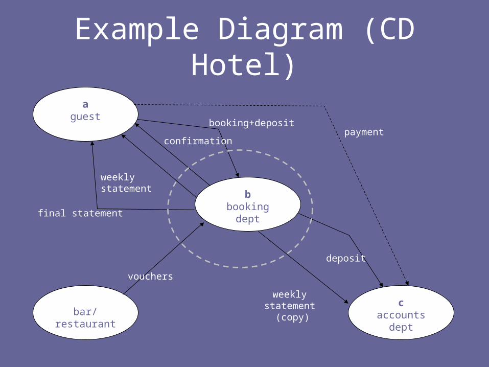
Identifying the system boundary
• This is rarely an easy task• There may be different opinions on this
boundary• Unless it is finalised development will fail
• Once identified, the boundary will be clearly stated in the terms of reference for the project
Example Diagram (CD Hotel)
aguest
bbooking
dept
caccounts
dept
dbar/
restaurant
booking+depositpayment
weekly statement
final statement
confirmation
vouchers
weekly statement (copy)
deposit
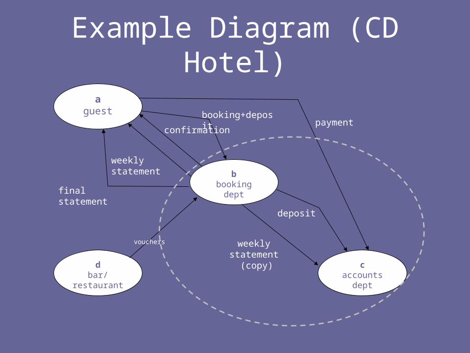
Example Diagram (CD Hotel)
aguest
bbooking
dept
caccounts
dept
d
bar/restaurant
booking+depositpayment
weekly statement
final statement
confirmation
vouchers
weekly statement (copy)
deposit
Example Diagram (CD Hotel)
aguest
bbooking
dept
caccounts
dept
dbar/
restaurant
booking+deposit payment
weekly statement
final statement
confirmation
vouchers weekly statement
(copy)
deposit
Document Definitions
• It is important at this stage to identify the information in the documents that flow across the system boundary
• These will inform us of the interface between the system and external entities– Data Interface and possibly GUI
• These will form the basis of our data dictionary
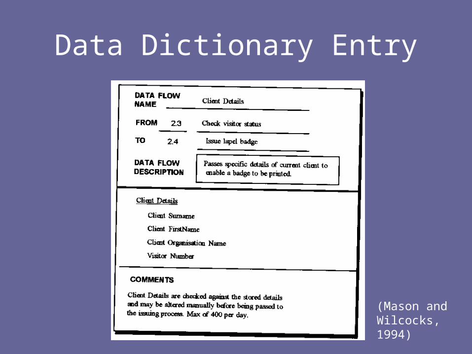
Data Dictionary Entry
(Mason and Wilcocks, 1994)
DFD Context Diagram
• Now that the system boundary has been established we can show the context in which our system operates– All internal details are removed– System boundary is changed to a process
box– All input and output data flows have been
identified

Example Diagram (CD Hotel)
aguest
bbooking
dept
caccounts
dept
dbar/
restaurant
booking+depositpayment
weekly statement
final statement
confirmation
vouchers
weekly statement (copy)
deposit

Example Diagram (CD Hotel)
aguest
bbooking
dept
caccounts
dept
d
bar/restaurant
booking+depositpayment
weekly statement
final statement
confirmation
vouchers
weekly statement (copy)
deposit

Example Diagram (CD Hotel)
aguest
bbooking
dept
caccounts
dept
d
bar/restaurant
booking+depositpayment
weekly statement
final statement
confirmation
vouchersweekly statement
(copy)
deposit
Example Diagram (CD Hotel)
aguest
bbooking dept
caccounts
dept
dbar/
restaurant
booking+deposit
weekly statement
final statement
confirmation
vouchersweekly statement
(copy)
deposit
CD HotelBookings

DFD Context Diagram
We now know what Systemwe are going to develop
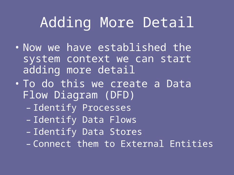
Adding More Detail
• Now we have established the system context we can start adding more detail
• To do this we create a Data Flow Diagram (DFD)– Identify Processes– Identify Data Flows– Identify Data Stores– Connect them to External Entities

• Process Box– Symbol
• Active Component• What goes in must come out or be transformed• Physical or Logical?
Create Reservation
1 Sales Assistant
Maintain Sales Account
2 Accounts Dept
*
Elements of a DFD
Indicates Process at lowest level of detail
Elements of a DFD
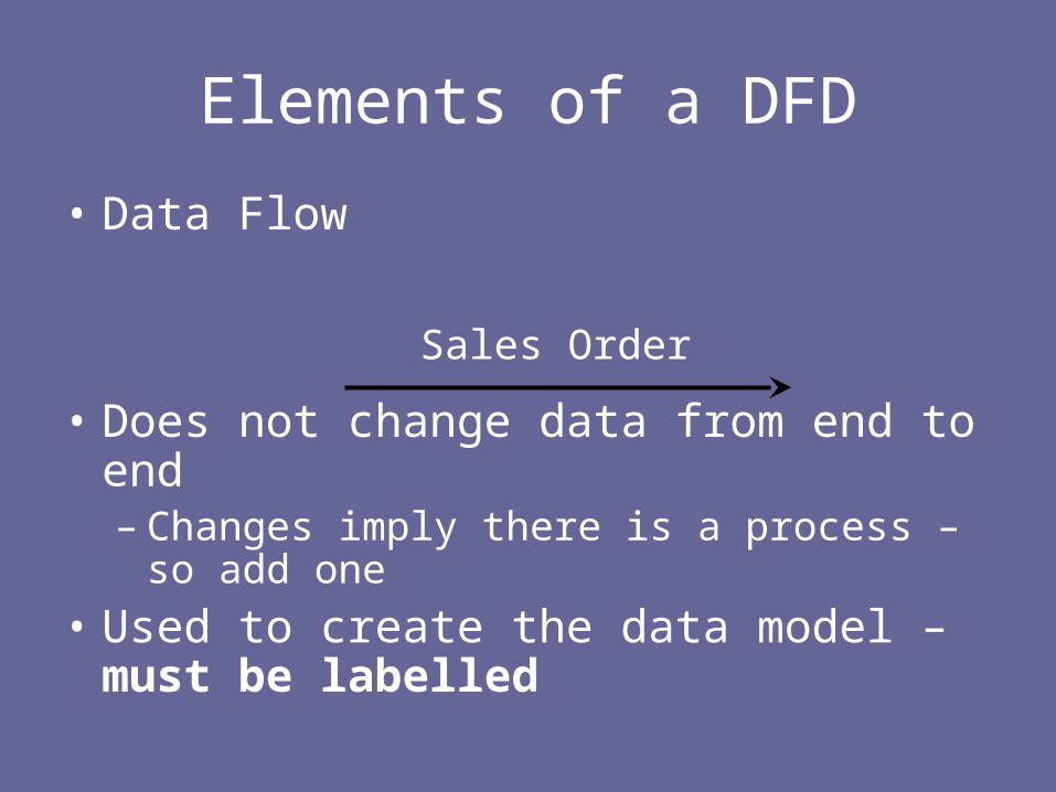
• Data Flow
• Does not change data from end to end– Changes imply there is a process – so add
one
• Used to create the data model – must be labelled
Sales Order
Elements of a DFD
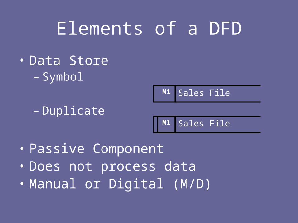
• Data Store– Symbol
– Duplicate
• Passive Component• Does not process data• Manual or Digital (M/D)
Sales FileM1
Sales FileM1
Elements of a DFD
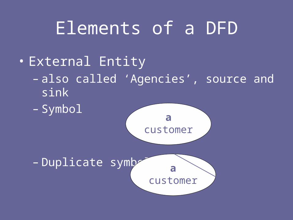
• External Entity – also called ‘Agencies’, source and sink– Symbol
– Duplicate symbol
acustomer
acustomer
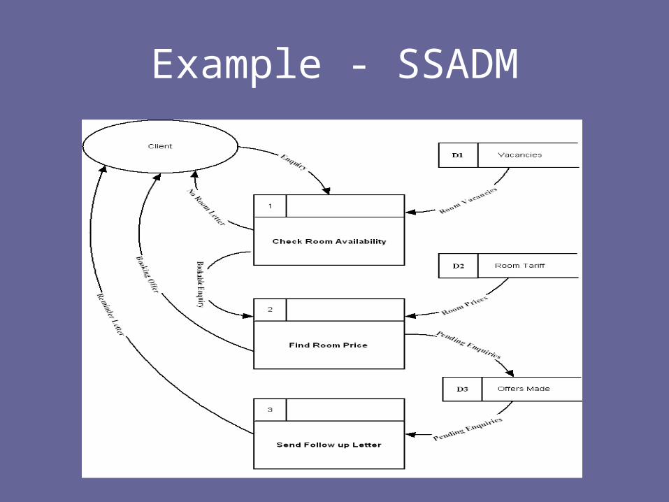
Example - SSADM
Example (CD Hotel)
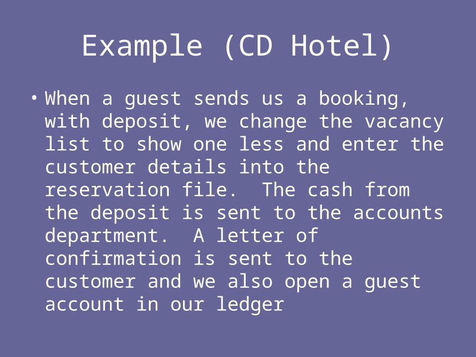
• When a guest sends us a booking, with deposit, we change the vacancy list to show one less and enter the customer details into the reservation file. The cash from the deposit is sent to the accounts department. A letter of confirmation is sent to the customer and we also open a guest account in our ledger
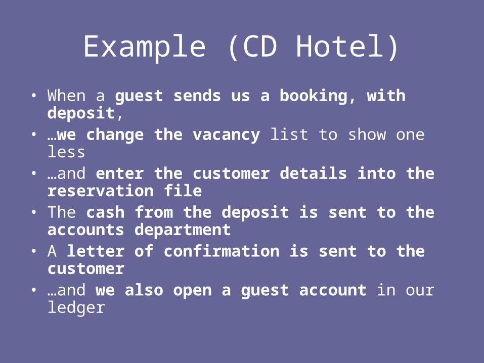
Example (CD Hotel)
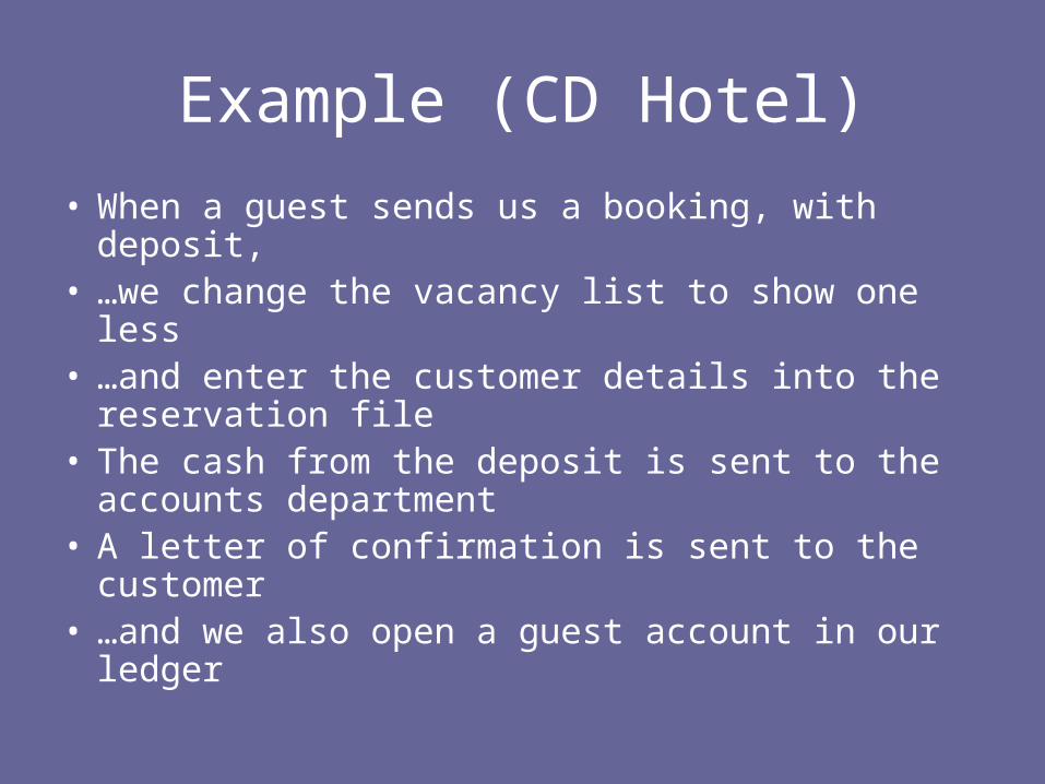
• When a guest sends us a booking, with deposit, • …we change the vacancy list to show one less • …and enter the customer details into the
reservation file• The cash from the deposit is sent to the
accounts department• A letter of confirmation is sent to the customer • …and we also open a guest account in our
ledger
Example (CD Hotel)
aguest
bbooking dept
caccounts
dept
dbar/
restaurant
booking+deposit
weekly statement
final statement
confirmation
vouchersweekly statement
(copy)
deposit
CD HotelBookings
Identifying Processes
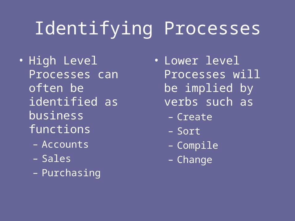
• High Level Processes can often be identified as business functions– Accounts– Sales– Purchasing
• Lower level Processes will be implied by verbs such as– Create– Sort– Compile– Change

Example (CD Hotel)
• When a guest sends us a booking, with deposit, • …we change the vacancy list to show one less • …and enter the customer details into the
reservation file• The cash from the deposit is sent to the
accounts department (splitting documents)• A letter of confirmation is sent to the customer • …and we also open a guest account in our
ledger

Example (CD Hotel)
aguest
bbooking dept
caccounts
dept
dbar/
restaurant
booking+deposit
weekly statement
final statement
confirmation
vouchersweekly statement
(copy)
deposit
CD HotelBookings
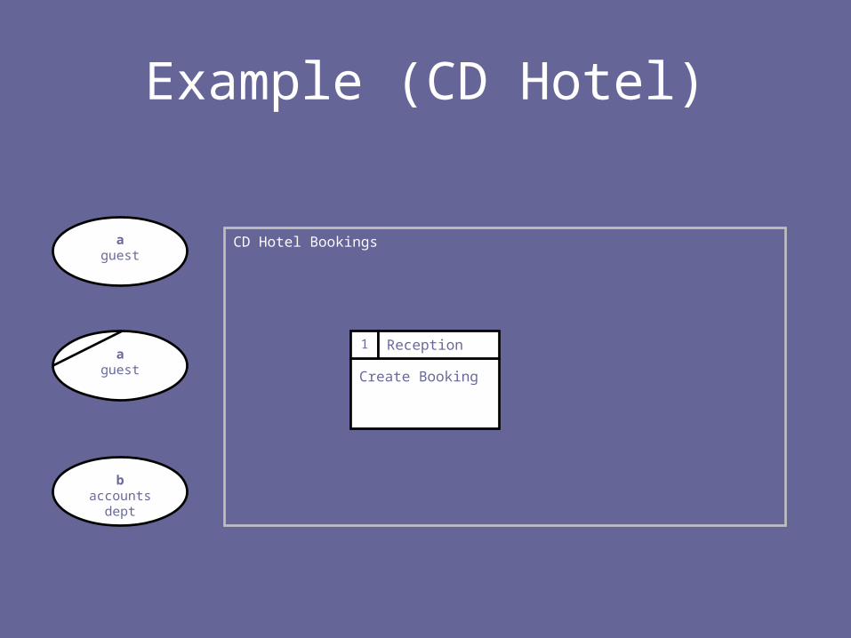
Example (CD Hotel)
CD Hotel Bookings
Create Booking
1 Reception
aguest
aguest
baccounts
dept

Identifying data Stores
• These may be obvious:– File– Catalogue– Tray– Folder– Database
• ..or implied– Check against– Put into– Read

Example (CD Hotel)
• When a guest sends us a booking, with deposit, • …we change the vacancy list to show one less • …and enter the customer details into the
reservation file• The cash from the deposit is sent to the
accounts department• A letter of confirmation is sent to the customer • …and we also open a guest account in our
ledger

Example (CD Hotel)
CD Hotel Bookings
Create Booking
1 Reception
aguest
aguest
baccounts
dept

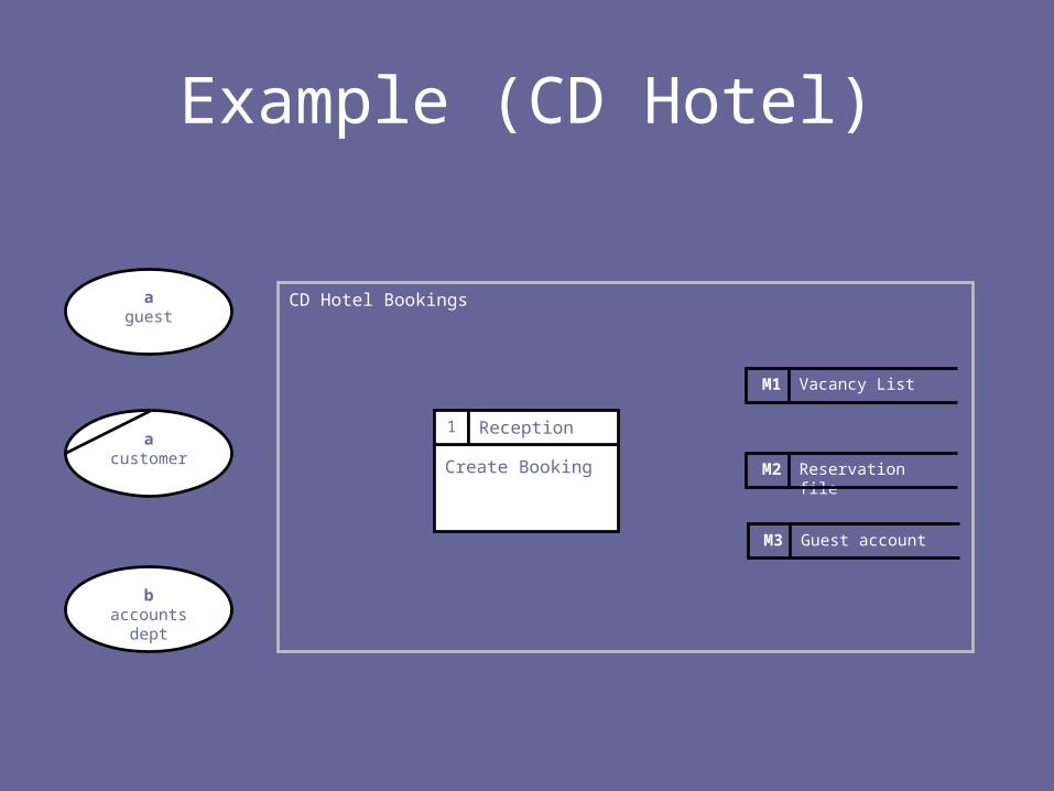
Example (CD Hotel)
CD Hotel Bookings
Create Booking
1 Reception
M1 Vacancy List
M2 Reservation file
M3 Guest account
aguest
acustomer
baccounts
dept
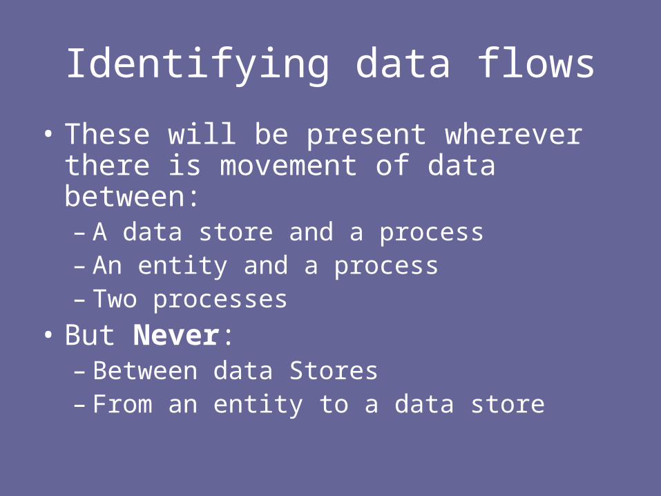
Identifying data flows
• These will be present wherever there is movement of data between:– A data store and a process– An entity and a process– Two processes
• But Never:– Between data Stores– From an entity to a data store
Example (CD Hotel)
• When a guest sends us a booking, with deposit, • …we change the vacancy list to show one less • …and enter the customer details into the reservation
file• The cash from the deposit is sent to the accounts
department• A letter of confirmation is sent to the customer • …and we also open a guest account in our ledger
Example (CD Hotel)
CD Hotel Bookings
Create Booking
1 Reception
M1 Vacancy List
M2 Reservation file
M3 Guest account
aguest
acustomer
baccounts
dept

Example (CD Hotel)
CD Hotel Bookings
Create Booking
1 Reception
booking+deposit M1 Vacancy List
M2 Reservation file
M3 Guest account
aguest
acustomer
baccounts
dept
guest details
room details
depositconfirmation
deposit
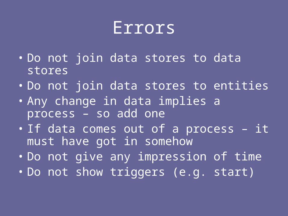
Errors
• Do not join data stores to data stores• Do not join data stores to entities• Any change in data implies a process – so
add one• If data comes out of a process – it must
have got in somehow• Do not give any impression of time• Do not show triggers (e.g. start)
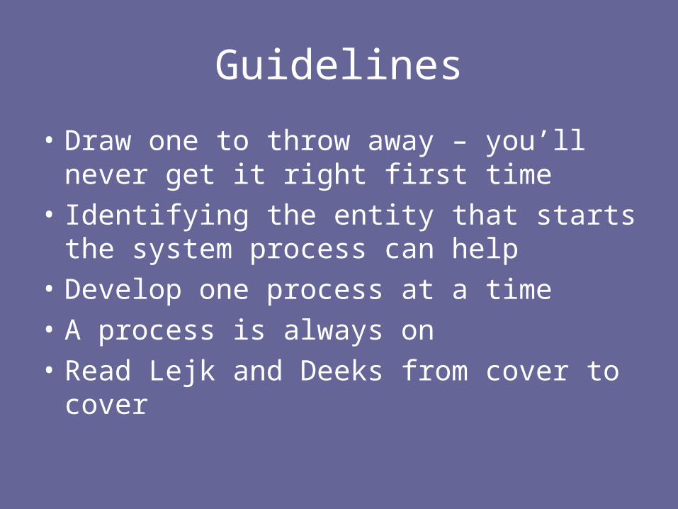
Guidelines
• Draw one to throw away – you’ll never get it right first time
• Identifying the entity that starts the system process can help
• Develop one process at a time
• A process is always on
• Read Lejk and Deeks from cover to cover

Plan
• Introduction
• Structured Methods– Data Flow Modelling
– Data Modelling
– Relational Data Analysis
• Feasibility
• Maintenance
References
• Whiteley, D. (2004) Introduction to Information Systems, Palgrave, 2004.
• Lejk, M. and D. Deeks (2002) Systems Analysis Techniques, Addison Wesley 2002
• Mason, D. and L. Willcocks (1994), Systems Analysis, Systems Design, Alfred Waller, 1994.

References
• Yeates, D. and T. Wakefield (2004) Systems Analysis and Design, FT/Prentice Hall 2004
• Gane, C. and T. Sarson (1979) Structured Systems Analysis, Prentice Hall, 1979
• Eva, M (1994) SSADM Version 4: A users guide, McGraw hill, 1994
References
• DeMarco, T. (1979) Structured Analysis and System Specification, Yourdon, 1979
• Royce, W. (1970) Managing the development of large software systems, In: Proceedings of IEEE WESCON, 1970 pp1-9.