system overview safety setup & installation operation ... · system overview safety setup &...
TRANSCRIPT
ATS 23005 1/2009 R1
System Overview Safety
Setup & Installation Operation
Maintenance
ATS 23005 1/2009 R1
SECOND EDITION, JANUARY 2009
Information in this document is subject to change without notice and does not represent a commitment on the part of Applied Test Systems, Inc. The software described in this document is furnished under a license agreement or nondisclosure agreement. The software may be used or copied only in accordance with the terms of the agreement. It is against the law to copy the software on any medium except as specifically allowed in the license or nondisclosure agreement.
Comments or suggestions pertaining to the contents of this manual can be sent to the address below:
Editor/Technical Manuals Applied Test Systems, Inc.
154 East Brook Lane Butler, PA 16002
Information you supply may be used by ATS without obligation. Necessary changes will be made in future editions of this manual.
© Copyright Applied Test Systems 2009 Windows and Excel are registered trademarks of the Microsoft Corporation For assistance with set-up or operation, contact the ATS Service Department. Please have this manual and product serial number available when you call.
Telephone: (724) 283-1212 – FAX (724) 283-6570
ATS 23005 1/2009
SERIES 540 COMPUTERIZED VERTICAL SEALANT TESTER
1 of 18 540 Manual Rev.1
Table of Contents
Section Title Page No.
SECTION 1. SYSTEM OVERVIEW 3 A. GENERAL DESCRIPTION 3 B. SPECIFICATIONS 5 D. COMPUTER CONTROL SYSTEM SOFTWARE 6
SECTION 2. SAFETY 7 A. FOR OWNERS, OPERATORS, AND MAINTENANCE PERSONNEL 9
SECTION 2. SAFETY 10
SECTION 3. SOFTWARE 11
SECTION 4. INSTALLATION 15 A. UNPACKING THE EQUIPMENT 15 B. CONNECTING THE EQUIPMENT 15 C. SOFTWARE INSTALLATION 15
SECTION 5. SETUP AND OPERATION 16
SECTION 6. MAINTENANCE 18
ATS 23005 1/2009
SERIES 540 COPMUTERIZED VERTICAL SEALANT TESTER
2 of 18 540 Manual Rev.1
PREFACE
Unpacking
Retain all cartons and packing materials until the unit is operated and found to be in good condition. If damage has occurred during shipping, notify Applied Test Systems and the carrier immediately. If it is necessary to file a damage claim, retain the packing materials for inspection by the carrier.
Warranty
All new ATS, Inc. systems are shipped with a warranty. Units have a warranty against defective parts and workmanship for one full year from date of shipment.
After-Sale Support
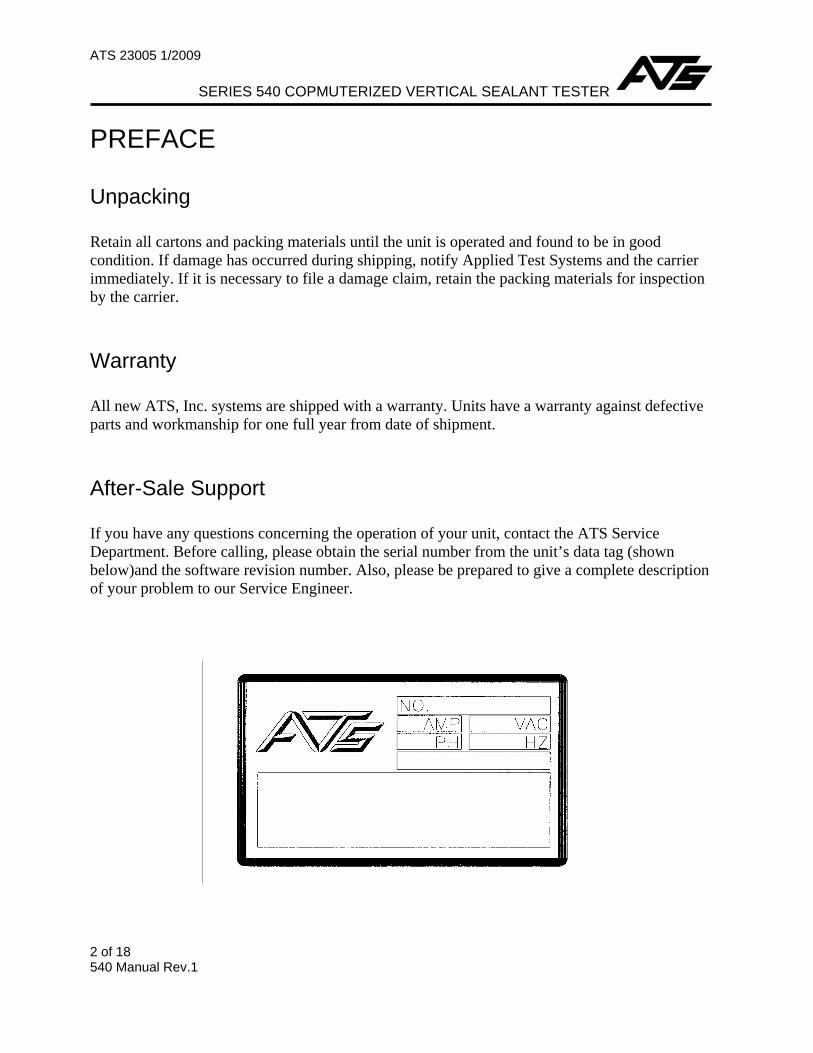
If you have any questions concerning the operation of your unit, contact the ATS Service Department. Before calling, please obtain the serial number from the unit’s data tag (shown below)and the software revision number. Also, please be prepared to give a complete description of your problem to our Service Engineer.

ATS 23005 1/2009
SERIES 540 COMPUTERIZED VERTICAL SEALANT TESTER
3 of 18 540 Manual Rev.1
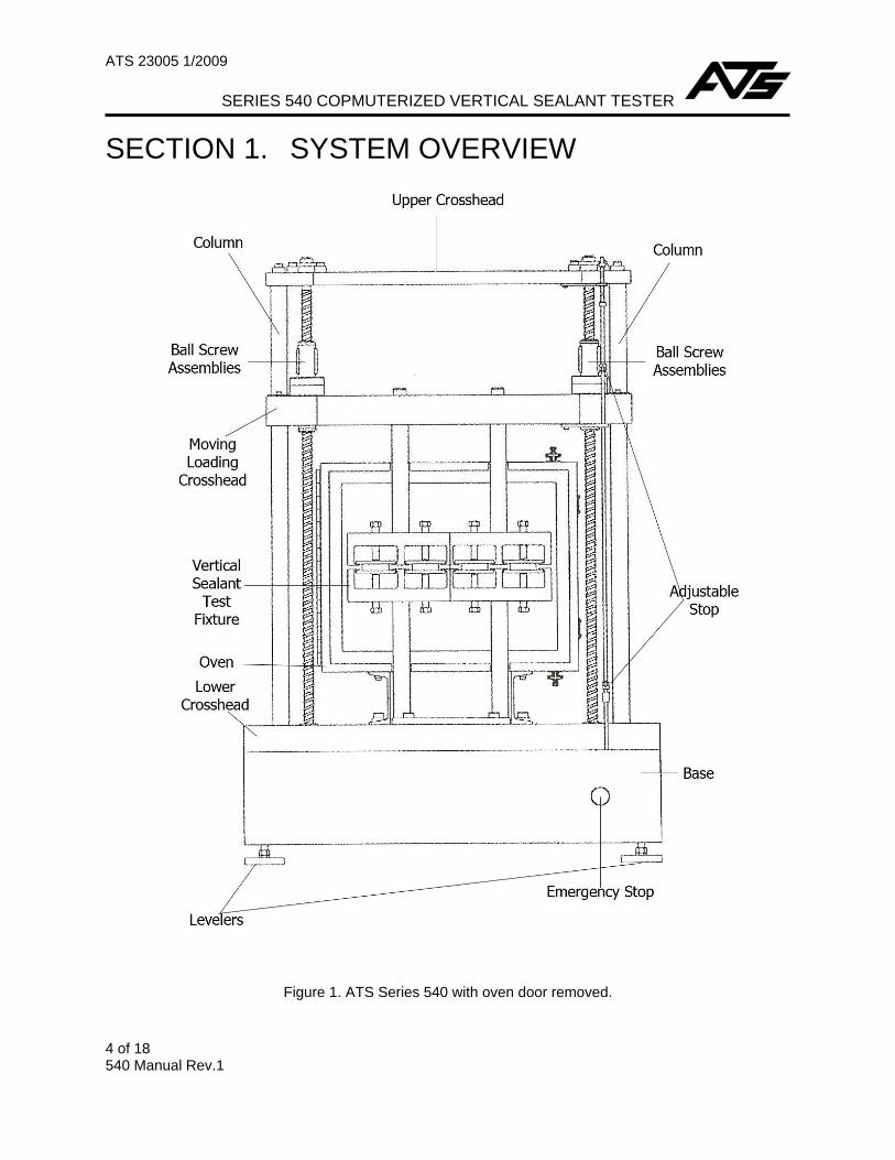
SECTION 1. SYSTEM OVERVIEW
A. General Description
The ATS Series 540 Computerized Vertical Sealant Tester is a bench top system designed to test sealants, adhesives, or coatings by applying alternating tension and compression cycles to the selected specimen. By aligining components in a vertical direction, the area occupied by the machine is kept to a minimum, efficiently increasing the utilization space in small laboratory spaces.
The ATS Series 540 can test up to 12 specimens simultaneously in capacities up to 5,000 lbs. (17.7kN) The samples are cycled a preset number of times at a selected distance and speed to simulate environmental conditions.
The ATS Series 540 test control function and data acquisition is operated by a Windows®-based personal computer. During testing, the software, ATS Cyclic Software, controls displacement, speed, and count and all of which are fully adjustable. In addition, the screen displays provide continuous information about test variables.
Standard test methods covered by the ATS 500 Series sealant testing machines include ASTM C719, C836, C910, and C920; JIS (Japanese Institute of Standards) 9010; U.S. Federal SS-S200, TT-S227, and TT-S230. The ATS Series 540’s design does not allow for it to perform any additional functions other than the intended functions specified in this manual.
The ATS Series 540 Load Frame is constructed of a base, columns, an upper crosshead, and a moving crosshead. Other essential parts include the crosshead limit system and personal computer with Ethernet/network port that contains the ATS Cyclic software that controls the ATS Series 540 during a test.
The base houses an electronically controlled, variable speed motor and low inertia drive system capable of a wide speed of bandwidth. A zero backlash ball screw drive system operates the moving crosshead which can be equipped with various testing accessories.
A crosshead limit system is provided with both fixed and user – adjustable stops. The fixed stops are factory preset to prevent damaging the crosshead over travel conditions. The crosshead limit system provides a means for the user to set custom travel limits on the crosshead based on specific tests.
ATS 23005 1/2009
SERIES 540 COPMUTERIZED VERTICAL SEALANT TESTER
4 of 18 540 Manual Rev.1
SECTION 1. SYSTEM OVERVIEW
Figure 1. ATS Series 540 with oven door removed.

ATS 23005 1/2009
SERIES 540 COMPUTERIZED VERTICAL SEALANT TESTER
5 of 18 540 Manual Rev. 1
B. Specifications
1. Load Frame
Capacity 5,000 lb.(22.24kN)
Clearance Horizontal: 20 ¾ in. (527 mm) between screws
Crosshead Speed Accuracy 0.05% of indicated speed
Crosshead Travel 4 in. (101 mm) without chamber; 2 in. (50.8 mm) with chamber
Speed Range 0.0001-2.0 in. / min. (.025-50 mm / min.)
2. Specimen Fixtures
Specimen Capacity 12 specimens 3 in. (76.2 mm) long by 2 in. (50.8 mm) wide by 1 in. ( 25.4 mm)tall
Fixture Capacity 5,000 lb. (22.24kN)
3. General
Height 46 ¼ in. (1174 mm)
Width 31 ½ in. (800 mm)
Depth 26 in. (660 mm) 30 in. (762 mm) with chamber
Shipping Weight 700 lb. (3.114kN) approximate
Power Requirements 230 VAC, 1 Phase, 60 Hz.
4. Computer System
The computer system must meet the following minimum specifiations:
Operating System Windows® 95, 98, ME, NT 4.0, 2000, XP Memory (RAM) 64 Megabytes for Windows® 95, 98, ME 128 Megabytes for Windows® NT 4.0, 2000, XP Hard Disk 15 Megabytes free space Processor Intel Celeron® 500 MHz or better Display Video Graphics Array (VGA) CD-ROM Drive Required for software installation
NOTE: Specifications subject to change without notice

ATS 23005 1/2009
SERIES 540 COPMUTERIZED VERTICAL SEALANT TESTER
6 of 18 540 Manual Rev.1
SECTION 1. SYSTEM OVERVIEW C. Environmental Conditions
The ATS Series 540 is designed for use in an industry/laboratory setting. It is designed for an indoor and dry environment. The unit should be placed on a clean, stable work surface.
D. Computer Control System Software
The computer control system software provides user control of the ATS Series 540 system in a Windows® environment with keyboard and/or mouse access to the functions. The software provides pull-down menus, button selections, and data entry text boxes for easy update and access to information.
During operation, the software collects and records the data from the various sensors within the ATS Series 540. The software is organized so all the information required to conduct a particular test is stored in the computer
Procedures in this manual assume the operator has experience working in a Windows environment.
ATS 23005 1/2009
SERIES 540 COMPUTERIZED VERTICAL SEALANT TESTER
7 of 18 540 Manual Rev. 1
SECTION 2. SAFETY
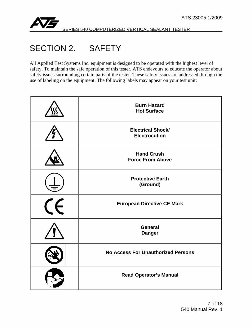
All Applied Test Systems Inc. equipment is designed to be operated with the highest level of safety. To maintain the safe operation of this tester, ATS endevours to educate the operator about safety issues surrounding certain parts of the tester. These safety issues are addressed through the use of labeling on the equipment. The following labels may appear on your test unit:
Burn Hazard Hot Surface
Electrical Shock/
Electrocution
Hand Crush
Force From Above
Protective Earth
(Ground)
European Directive CE Mark
General Danger
No Access For Unauthorized Persons
Read Operator’s Manual
ATS 23005 1/2009
SERIES 540 COPMUTERIZED VERTICAL SEALANT TESTER
8 of 18 540 Manual Rev.1
Safety Instructions
ATS 23005 1/2009
SERIES 540 COMPUTERIZED VERTICAL SEALANT TESTER
9 of 18 540 Manual Rev. 1
SECTION 2. SAFETY CONT.
A. For Owners, Operators, and Maintenance Personnel
Read and understand all instructions and safety precautions listed in this manual before installing or operating your unit. If you have any questions regarding operation of the unit or instructions in this manual, contact the ATS Service Department.
In addition to the safety warnings listed below, warnings are posted throughout the manual. Read and follow these important instructions. Failure to observe these instructions can result in permanent damage to the unit, significant property damage, personal injury, or death.
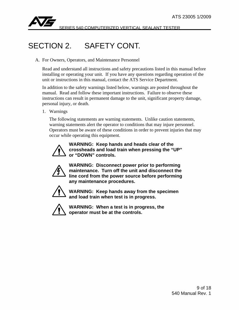
1. Warnings
The following statements are warning statements. Unlike caution statements, warning statements alert the operator to conditions that may injure personnel. Operators must be aware of these conditions in order to prevent injuries that may occur while operating this equipment.
WARNING: Keep hands and heads clear of the crossheads and load train when pressing the “UP” or “DOWN” controls.
WARNING: Disconnect power prior to performing maintenance. Turn off the unit and disconnect the line cord from the power source before performing any maintenance procedures.
WARNING: Keep hands away from the specimen and load train when test is in progress.
WARNING: When a test is in progress, the operator must be at the controls.
ATS 23005 1/2009
SERIES 540 COPMUTERIZED VERTICAL SEALANT TESTER
10 of 18 540 Manual Rev.1
SECTION 2. SAFETY CONT. 2. Cautions
The following statements are caution statements. These statements alert the operator to conditions that may damage equipment. Operators must be aware of these conditions in order to ensure safe operation of this equipment.
CAUTION: Installation of electrical devices must be accomplished by competent personnel and done in accordance with any current local and national codes. Equipment grounding is a MUST
CAUTION: Before energizing the electrical power to the ATS Series 540, turn off all power switches and place all controls in an OFF or neutral position. Check that your power source is of the appropriate voltage and is surge-protected. Use appropriate power adapters based upon your region.
CAUTION: Do not exceed the rate capacity of the adapters, grips, or load cell. Damage to your equipment may result.
CAUTION: Do not lift the ATS Series 540 by the loading crosshead. Damage to your equipment may result. Lift it only under the housing, or by the adjustable crosshead.
CAUTION: The load cell capacity of the load train component is reduced at elevated temperatures.
CAUTION: Observe maximum temperature ratings of test components (extensometer, grips, fixtures, couplings, etc.)
ATS 23005 1/2009
SERIES 540 COMPUTERIZED VERTICAL SEALANT TESTER
11 of 18 540 Manual Rev. 1
SECTION 3. SOFTWARE
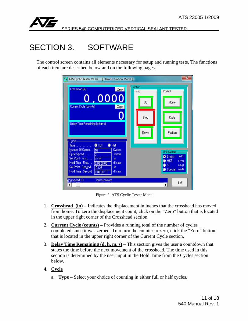
The control screen contains all elements necessary for setup and running tests. The functions of each item are described below and on the following pages.
Figure 2. ATS Cyclic Tester Menu
1. Crosshead (in) – Indicates the displacement in inches that the crosshead has moved
from home. To zero the displacement count, click on the “Zero” button that is located in the upper right corner of the Crosshead section.
2. Current Cycle (counts) – Provides a running total of the number of cycles completed since it was zeroed. To return the counter to zero, click the “Zero” button that is located in the upper right corner of the Current Cycle section.
3. Delay Time Remaining (d, h, m, s) – This section gives the user a countdown that states the time before the next movement of the crosshead. The time used in this section is determined by the user input in the Hold Time from the Cycles section below.
4. Cycle a. Type – Select your choice of counting in either full or half cycles.
ATS 23005 1/2009
SERIES 540 COPMUTERIZED VERTICAL SEALANT TESTER
12 of 18 540 Manual Rev.1
b. Number of Cycles – Enter the number of cycles you would like to run. The test will automatically stop when this number of cycles dictated has been reached.
c. Cyclic Speed – Enter the speed of the crosshead in inches per minute.
d. Set Point-First - (First motion position from Zero) selects the displacement and direction to which the crosshead will travel before reversing the cycle. With respect to zero, a positive value will cause the crosshead to move in an upward direction (compression), and a negative value will cause the crosshead to move down (tension). Enter desired Set Point-First value here.
e. Set Point-Second – (Second motion position from zero) is used to place a specimen under both tension and compression. Enter desired value, selecting the displacement and direction to which the crosshead will travel after completing the first cycle set.
f. Jog Speed – Increase or decrease the Jog Speed by selecting the box below the display, clicking and dragging the box to increase and / or decrease the jog speed.
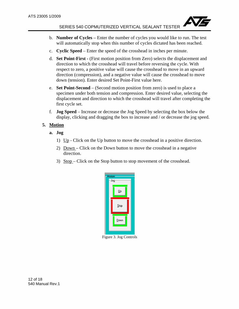
5. Motion
a. Jog 1) Up - Click on the Up button to move the crosshead in a positive direction.
2) Down – Click on the Down button to move the crosshead in a negative direction.
3) Stop – Click on the Stop button to stop movement of the crosshead.
Figure 3. Jog Controls

ATS 23005 1/2009
SERIES 540 COMPUTERIZED VERTICAL SEALANT TESTER
13 of 18 540 Manual Rev. 1
b. Control 1) Home – Click on the Home button to return the crosshead to the zero position.
2) Cycle – Click the Cycle button to start the cyclic operation. A confirmation window that looks like the image below will pop up. Click on OK to continue the operation, or click on the Cancel button to cancel the operation.
Figure 4. Motion Control
Figure 5. Cycle Confirmation Window
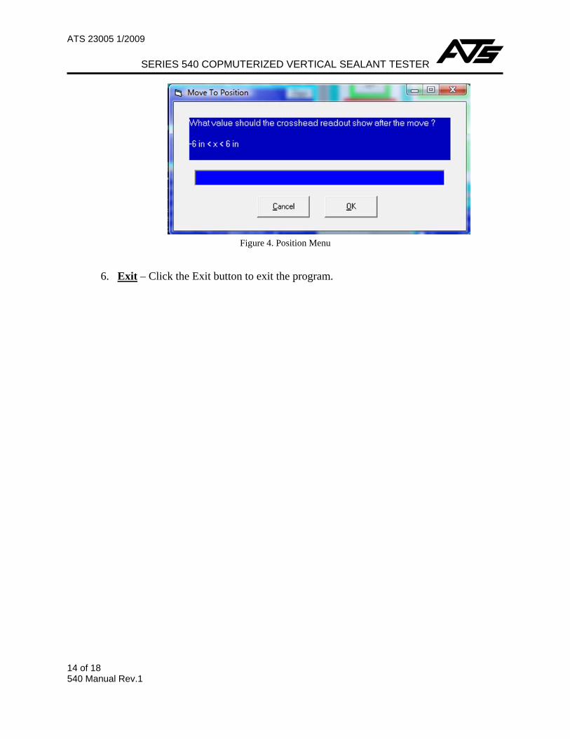
3) Position – Click the Position button to enter the value that the crosshead readout should show after the movement.
ATS 23005 1/2009
SERIES 540 COPMUTERIZED VERTICAL SEALANT TESTER
14 of 18 540 Manual Rev.1
Figure 4. Position Menu
6. Exit – Click the Exit button to exit the program.
ATS 23005 1/2009
SERIES 540 COMPUTERIZED VERTICAL SEALANT TESTER
15 of 18 540 Manual Rev. 1
SECTION 4. INSTALLATION
A. Unpacking the Equipment
1. Remove the ATS 540 Vertical Sealant Tester load frame and computer from the crate.
2. Place the load frame on a sturdy work surface
3. Place the computer system on the work surface near the load frame.
4. Inspect the equipment and computer system to be sure there wasn’t any damage during shipment. If damage is found, notify the shipping company and the ATS Service Department.
B. Connecting the Equipment
1. Please use the following connection cables that were shipped with the ATS Series 540.
a. Main Power Cable
b. Communication Cable
2. Connect the main power cable from the bottom right back of the base to the power supply.
3. Connect the communication cable in the bottom left of the tester base and the computer.
4. When connecting additional equipment to the computer, refer to the manufacturer’s literature for details.
C. Software Installation
NOTE: Systems that were shipped from the factory have the software already installed on the computer that is set up to work with the ATS Series 540. The following instructions only apply to those whom purchased a computer separately.
1. Turn the computer on, and wait until the computer initializes. Place the CD in the CD ROM and follow the computer’s instructions.
ATS 23005 1/2009
SERIES 540 COPMUTERIZED VERTICAL SEALANT TESTER
16 of 18 540 Manual Rev.1
SECTION 5. SETUP AND OPERATION
A. Before energizing the electrical power to the ATS Series 540, set the power control to the “off” position.
CAUTION: Before energizing the electrical power to the ATS Series 540, turn off all power switches and place all controls in an OFF or neutral position. Check that your power source is of the appropriate voltage and is surge-protected. Use appropriate power adapters based upon your region.
B. Turn the main power breaker to the frame to the “on” position and turn on the computer.
C. Determine and /or review test requirements for all components of the system. Run the software, and program accessory equipment to the test requirements (for example - programming a temperature controller or measuring device).
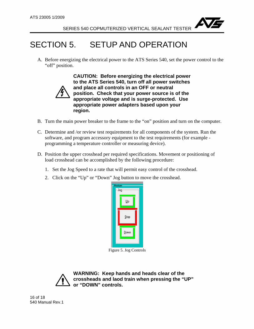
D. Position the upper crosshead per required specifications. Movement or positioning of load crosshead can be accomplished by the following procedure:
1. Set the Jog Speed to a rate that will permit easy control of the crosshead.
2. Click on the “Up” or “Down” Jog button to move the crosshead.
Figure 5. Jog Controls
WARNING: Keep hands and heads clear of the crossheads and laod train when pressing the “UP” or “DOWN” controls.
ATS 23005 1/2009
SERIES 540 COMPUTERIZED VERTICAL SEALANT TESTER
17 of 18 540 Manual Rev. 1
E. Make sure that the ATS 540 and it’s fixture have been properly positioned to allow efficient installation of the specimen.
F. Load the specimen, and tighten fixtures bolts to check positioning of fixtures and accessories, if so desired, to assist in selecting test procedures to match testing requirements.
G. Select and install accessories required for the test.
H. Position the adjustable stops to prevent accidental damage to the testing accessories. The upper stop is used to prevent ramming of the load train components together. The upper or lower halves of the fixture should never come closer then .020 in. (0.5 mm) If a furnace or oven is used, the lower stop should be used to prevent damage to the “inner top” of the oven / furnace from over travel of the test fixture.
I. Make sure the specimen(s) is properly mounted. Check the fixture, accessories, and lower stops.
J. Set your test parameters in your software.
K. If any accessory equipment (chart recorder, temperature conditioning equipment, etc.) is being used, start it at this time.
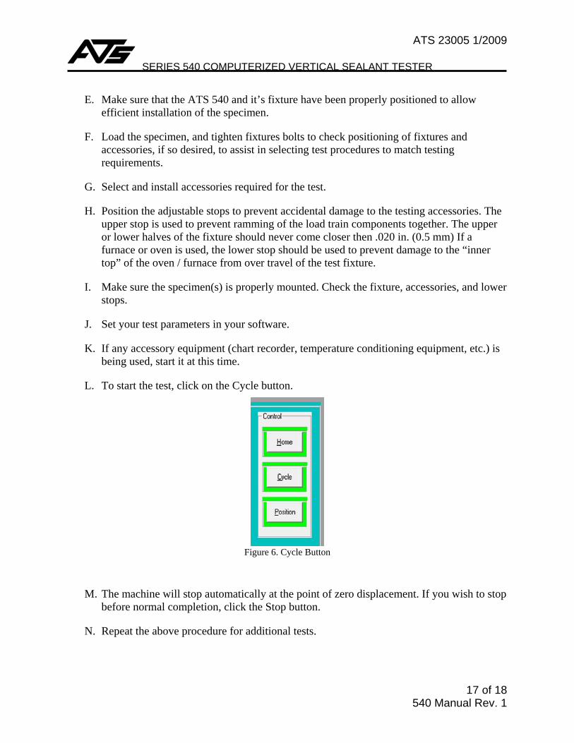
L. To start the test, click on the Cycle button.
Figure 6. Cycle Button
M. The machine will stop automatically at the point of zero displacement. If you wish to stop before normal completion, click the Stop button.
N. Repeat the above procedure for additional tests.
ATS 23005 1/2009
SERIES 540 COPMUTERIZED VERTICAL SEALANT TESTER
18 of 18 540 Manual Rev.1
SECTION 6. MAINTENANCE
A. The ATS Series 540 is relatively maintenance free. However, some basic procedures should be followed to keep your system running trouble free. Information for specific components of the system is contained within the manufacturers’ literature included with this manual. This includes information concerning the mechanical elements such as gear reducer, drive assembly, and the servo motor system.
B. Inspect the ATS Series 540 test fixture periodically, and always check the fasteners are tight and the mating surfaces of the fixture are parallel within .005 in. (0.127 mm). If the fixture is out of parallel or visibly damaged, discontinue use and contact the ATS Service Department
C. To facilitate smooth movement of the crosshead, lubricate the ball screws of the ATS 540 when needed. We recommend using Dow Corning 321 Dry Film Lubricant. Follow the manufacturer’s instructions.
1. Move the crosshead to a position that will expose the maximum vertical length of the ball screws. If the test area is below the crosshead, this position will be at the uppermost point of travel and vice versa. The adjustable limit stops will likely need to be moved. Do not change the position of the factory set fixed stops.
2. When the ball screws are sufficiently coated, return the crosshead and the adjustable stops to the appropriate positions to resume testing.