installation and appliance setup - care and operation
TRANSCRIPT
11 3-90-30007480Hearth and Home Technolgies • Oxford Direct/Natural Vent Installation Manual_R19 • 11/21
Installation & Operating ManualInstallation and Appliance Setup - Care and Operation
INSTALLER: Leave this manual with party responsible for use and operation.OWNER: Retain this manual for future reference.Call your dealer for questions on Installation, Operation, or Service.
FIRE OR EXPLOSION HAZARDFailure to follow safety warnings exactly could result in serious injury, death or property damage.• Donotstoreorusegasolineorotherflammable
vapors and liquids in the vicinity of this or any other appliance.
• WHAT TO DO IF YOU SMELL GAS – Do not try to light any appliance. – Do not touch any electrical switch; do not use
any phone in your building. – Leave the building immediately. – Immediately call your gas supplier from a
neighbor’s phone. Follow the gas supplier’s instructions.
– If you cannot reach your gas supplier, call the firedepartment.
• Installation and service must be performed by a qualified installer, service agency or thegas supplier.
WARNING!
Installation and service of this appliance should be performed by qualified personnel. Hearth & Home Technologies recommends HHT Factory Trained or NFI certified professionals.
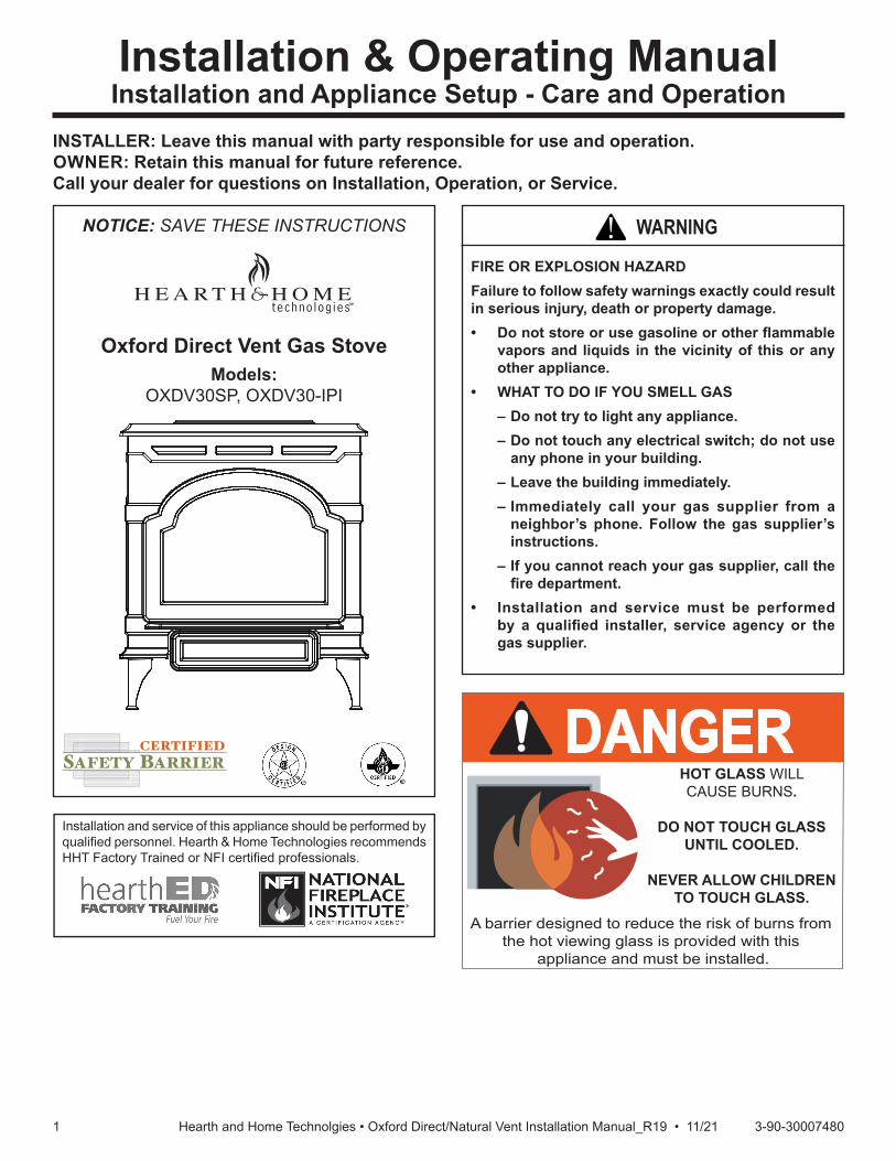
Oxford Direct Vent Gas StoveModels:
OXDV30SP, OXDV30-IPI
CERTIFIEDSAFETY BARRIER
NOTICE: SAVE THESE INSTRUCTIONS
5123Oxford cover
DANGERHOT GLASS WILLCAUSE BURNS.
DO NOT TOUCH GLASSUNTIL COOLED.
NEVER ALLOW CHILDRENTO TOUCH GLASS.
A barrier designed to reduce the risk of burns from the hot viewing glass is provided with this
appliance and must be installed.
22 3-90-30007480Hearth and Home Technolgies • Oxford Direct/Natural Vent Installation Manual_R19 • 11/21
PLEASE READ THE INSTALLATION & OPERATING INSTRUCTIONS BEFORE USING APPLIANCE.Thank you and congratulations on your purchase of a Hearth and Home Technologies stove. IMPORTANT: Read all instruc-tions and warnings carefully before starting installation. Failure to follow these instructions may result in a possible fire hazard and will void the warranty.
Table of Contents6 Operating Instructions ..........................................................33
A. Operation .............................................................................33B. Lighting Instructions .............................................................33C. Pilot and Burner Inspection ..................................................33D. Flame Characteristics ..........................................................33E. Flame and Temperature Adjustment ....................................33F. Read Before Lighting ...........................................................34G. Lighting and Operating Instructions .....................................35H. Lighting Instructions (IPI) .....................................................36I. Lighting Troubleshooting ......................................................37J. Burner, Pilot & Control Compartment ...................................40
7 Cleaning and Maintenance ...................................................41
A. Annual System Inspection ....................................................41B. Logset & Burner / Cleaning & Inspection .............................41C. Care of Cast Iron ..................................................................41D. Cleaning the Glass ...............................................................41E. Glass Replacement ..............................................................41F. Gasket Replacement ............................................................42G. Check the Gas Flame Regularly ..........................................42H. Stove Disassembly ...............................................................42I. Maintenance Frequency .......................................................43
8 Wiring Diagrams ....................................................................44
9 Service Parts List ..................................................................45
10 Optional Accessories ..........................................................51
11 Warranty Policy ....................................................................52
1 Important Safety Information
A. Massachusetts Safety Information .........................................4B. California Safety Information ..................................................4
2 Framing and Clearances
A. Appliance Dimension Diagram ...............................................5B. Installation Requirements .......................................................6C. Clearance Requirements .......................................................6D. Hearth Requirements .............................................................7E. Clearances to Combustibles ..................................................7F. Gas Specifications .................................................................8G. Vent Terminations & Clearances ............................................8H. Chimney Diagram ................................................................ 11
3 Assembly and Installation
A. Venting Requirements & Options .........................................13B. Assembling the Stove .........................................................14C. Venting System Assembly ....................................................14D. Log Set Installation ...............................................................24
4 Gas Information
A. Fuel Conversion ...................................................................25B. Gas Pressure .......................................................................25C. Gas Connection ...................................................................25D. High Altitude Installations .....................................................25E. Gas Supply Line Connection ................................................26F. Burner Information ...............................................................26G. Thermostat Connection (Optional) Millivolt ..........................28H. After Appliance is Lit .............................................................29I. Flame Adjustment Control ....................................................29J. Frequently Asked Questions ................................................29
5 Electrical Information ............................................................30
A. Wiring Requirements ............................................................30B. Intellifire Ignition System Wiring ...........................................30C. Optional Accessories Requirements ....................................30D. Electrical Service and Repair ...............................................30E. IPI Wiring Requirements ......................................................31F. Install the Safety Barrier .......................................................32G. Install the Mesh and Grille ....................................................32
= Contains updated information
33 3-90-30007480Hearth and Home Technolgies • Oxford Direct/Natural Vent Installation Manual_R19 • 11/21
The Oxford Direct Vent Room Heater, Model No. OXDV30SP, OXDV30IPI, is a vented gas appliance listed to the ANSI Standard Z21.88-2019 and CSA 2.33-2019 for Vented Room Heaters, and CSA 2.17-M91, Gas-Fired Appliances For Use at High Altitudes.The installation of the Oxford Direct Vent Room Heater must conform with local codes, or in the absence of local codes, with National Fuel Gas Code, ANSI Z223.1/NFPA 54 — latest edition and CSA B-149.1 Installation Code. (EXCEPTION: Do not derate this appliance for altitude up to 2,000 (610 m) for natural gas and 4,500 feet (1,370 m) for Propane Gas. Maintain the manifold pressure at 3.5” w.c. for Natural Gas and 10.0” w.c. for Propane Gas.) This appliance is only for use with the type of gas indicated on the rating plate. This appliance is not convertible for use with other gases unless a certified kit is used. Installation and replacement of gas piping, gas utilization equipment or accessories, and repair and servicing of equipment shall beperformedonly by a qualified agency,preferablyNFIorWETT(Canada)certified.Theterm“qualifiedagency”meansanyindividual,firm,corporation,orcompanythat either in person or through a representative is engaged in and is responsible for (a) installation or replacement of gas piping, or (b), the connection, installation, repair, or servicing of equipment, who is experienced in such work, familiar with all precautions required, and has complied with all the requirements of the authority having jurisdiction.The Oxford Direct Vent Room Heater should be inspected beforeuseandatleastannuallybyaqualifiedserviceagency.It is imperative that control compartments, burners, and circulating air passageways of the appliance be kept clean.The Oxford Direct Vent Room Heater and its individual shut-off valve must be disconnected from the gas supply piping during any pressure testing of that system at test pressures in excess of 1/2 psig (3.5 kPa).The Oxford Direct Vent Room Heater must be isolated from the gas supply piping system by closing its individual manual shutoff valve during any pressure testing of the gas supply piping system at test pressures equal to or less than 1/2 psig.An accessible tap is located above the pilot/On-Off knob for checking the inlet pressure.‘Direct Vent’ describes a sealed combustion system in which incoming outside air for combustion and outgoing exhaust enter and exit through two separate concentric passages within the same sealed vent system. The system does not use room air to support combustion. The Direct Vent system permits the gas appliance to be vented directly to the outside atmosphere through the side of the house or vertically through the roof. Conventional venting systems (Natural Vent) take air from the room for combustion and vent the exhaust vertically through the roof to the atmosphere.This appliance is approved for bedroom installations in the U.S. and Canada.This appliance may be installed in an aftermarket* manufactured (mobile) home, where not prohibited by state or local codes.WARNING: Operation of this heater when not connected to a properly installed and maintained venting system can result in carbon monoxide (CO) poisoning and possible death.
The Oxford Direct Vent Room Heater, when installed, must be electrically grounded in accordance with local codes or, in the absence of local codes, with the National Electrical Code ANSI/NFPA 70, (latest edition), or of the current Canadian Electrical Code C22.1.Due to high temperatures this appliance should be located out oftrafficandawayfromfurnitureanddraperies.WARNING: This appliance is hot while in operation. Keep children, clothing, and furniture away. Contact may cause burns or ignition of combustible materials.Children and adults should be alerted to the hazards of high surface temperatures and should stay away to avoid burns or clothing ignition. Young children should be carefully supervised when they are in the same room as the appliance. Toddlers, young children and others may be susceptible to accidental contact burns. A physical barrier is recommended if there are at risk individuals in the house. To restrict access to a stove or stove, install an adjustable safety gate to keep toddlers, young children and other at risk individuals out of the room and away from hot surfaces.A barrier is designed to reduce the risk of burns from the hot viewing glass is provided with this appliance and shall be installed for the protection of children and other at-risk individuals. If the barrier becomes damaged, the barrier shall be replaced with the manufacturer’s barrier for this appliance.Clothingorotherflammablematerialsshouldnotbeplacedon or near the appliance. Any safety screen, glass or guard removed for servicing an appliance must be replaced prior to operating the appliance.The appliance area must be kept clear and free from combustible materials,gasoline,andotherflammablevaporsandliquids.The flow of combustion and ventilation air must not be obstructed. The installation must include adequate accessibility and clearance for servicing and proper operation.WARNING: Do not operate the Room Heater with the glass panel removed, cracked or broken. Replacement of the panel should bedonebyalicensedorqualifiedserviceperson.Do not use this appliance if any part has been under water. Immediatelycallaqualifiedservicetechniciantoinspecttheappliance and to replace any part of the control system and any gas control which has been under water.Do not burn wood, trash or any other material for which this appliance was not designed. This appliance is designed to burn either natural gas or propane only.Thisgasappliancemustnotbeconnectedtoachimneyflueserving a separate solid-fuel burning appliance.CAUTION: Label all wires prior to disconnection when servicing controls. Wiring errors can cause improper and dangerous operation.Verify proper operation after servicing.* Aftermarket: Completion of sale, nor for purpose of resale, from the manufacturer.
1 1 Important Safety Information

44 3-90-30007480Hearth and Home Technolgies • Oxford Direct/Natural Vent Installation Manual_R19 • 11/21
A. Massachusetts Safety InformationRequirements for the Commonwealth of MassachusettsAll gas fitting and installation of this heater shall only be done by a licensed gas fitter or licensed plumber.For all side wall horizontally vented gas fueled equipment installed in every dwelling, building or structure used in whole or in part for residential purposes, including those owned or operated by the Commonwealth and where the side wall exhaust vent termination is less than seven (7) feet above finished grade in the area of the venting, including but not limited to decks and porches, the following requirements shall be satisfied:Installation of Carbon Monoxide DetectorsAt the time of installation of the side wall horizontal vented gas fueled equipment, the installing plumber or gas fitter shall observe that a hard wired carbon monoxide detector with an alarm is installed on each additional level of the dwelling, building or structure served by the side wall horizontal vented gas fueled equipment. It shall be the responsibility of the property owner to secure the services of qualified licensed professionals for the installation of hard wired carbon monoxide detectors.In the event that the side wall horizontally vented gas fueled equipment is installed in a crawl space or an attic, the hard wired carbon monoxide detector with alarm and battery back-up may be installed on the next adjacent floor level.In the event that the requirements of this subdivision can not be met at the time of completion of installation, the owner shall have a period of thirty (30) days to comply with the above requirements; provided, however, that during said thirty (30) day period, a battery operated carbon monoxide detector with an alarm shall be installed.Approved Carbon Monoxide DetectorsEach carbon monoxide detector as required in accordance with the above provisions shall comply with NFPA 720 and s/UL 2034 listed and IAS certified.SignageAmetalorplasticidentificationplateshallbepermanentlymounted to the exterior of the building at a minimum height of eight (8) feet above grade directly in line with the exhaust vent terminal for the horizontally vented gas fueled heating appliance or equipment. The sign shall read, in print size no less than one-half (1/2) inch in size, “GASVENTDIRECTLYBELOW,KEEPCLEAROFALLOBSTRUCTIONS".
ExemptionsThe following equipment is exempt from 248 CMR 5.08(2)(a)1 through 4:• The equipment listed in Chapter 10 entitled “Equipment
Not Required To Be Vented" in the most current edition of NFPA 54 as adopted by the Board; and
• Product Approved side wall horizontally vented gas fueled equipment installed in a room or structure separate from the dwelling, building or structure used in whole or in part for residential purposes.
Manufacturer RequirementsGas Equipment Venting System ProvidedWhen the manufacturer of Product Approved side wall horizontally vented gas equipment provides a venting system design or venting system components with the equipment, the instructions provided by the manufacturer for installation of the equipment and the venting system shall include:• Detailed instructions for the installation of the venting
system design or the venting system components; and• A complete parts list for the venting system design or
venting system.Gas Equipment Venting System NOT ProvidedWhen the manufacturer of a Product Approved side wall horizontally vented gas fueled equipment does not provide the parts for venting the flue gases, but identifies “special venting systems", the following requirements shall be satisfied by the manufacturer:• The referenced “special venting system" instructions
shall be included with the appliance or equipment installation instructions; and
• The “special venting systems" shall be Product Approved by the Board, and the instructions for that system shall include a parts list and detailed installation instructions.
A copy of all installation instructions for all Product Approved side wall horizontally vented gas fueled equipment, all venting instructions, all parts lists for venting instructions, and/or all venting design instructions shall remain with the appliance or equipment at the completion of the installation.
Oxford Direct VentCertifiedto:ANSIZ21.88-2019/CSA2.33-2019VentedGas Heaters
B. California Safety Information
InspectionThe state or local gas inspector of the side wall horizontally vented gas fueled equipment shall not approve the installation unless, upon inspection, the inspector observes carbon monoxide detectors and signage installed in accordance with the provisions of 248 CMR 5.08(2)(a)1 through 4.
This product and the fuels used to operate this product (wood), and the products of combustion of such fuels, can expose you to chemicals including carbon black, which is known to the State of California to cause cancer, and carbon monoxide, which is known to the State of California to cause birth defects or other reproductive harm. For more information go to: WWW.P65Warnings.ca.gov
WARNING
55 3-90-30007480Hearth and Home Technolgies • Oxford Direct/Natural Vent Installation Manual_R19 • 11/21
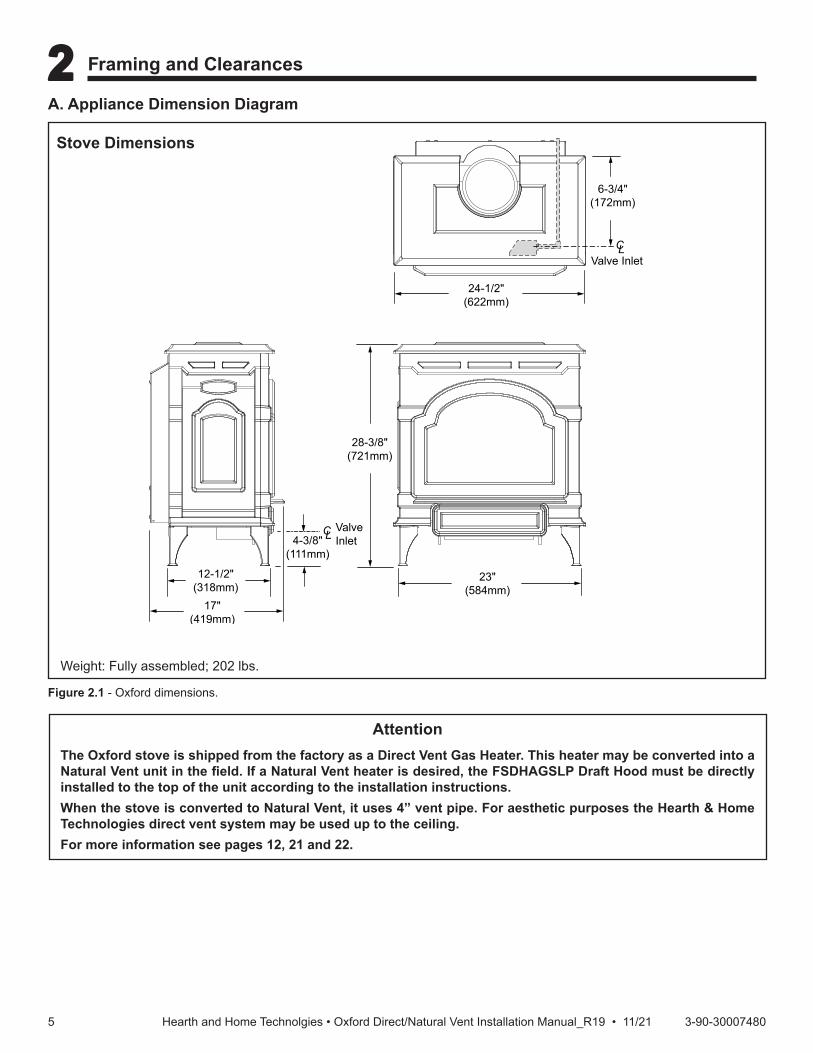
A. Appliance Dimension Diagram
Figure 2.1 - Oxford dimensions.
Stove Dimensions
2 2 Framing and Clearances
23"(584mm)
CLValve Inlet
6-3/4"(172mm)
24-1/2"(622mm)
CLValve Inlet
5123 Oxford dims
28-3/8"(721mm)
12-1/2"(318mm)
17"(419mm)
4-3/8"(111mm)
AttentionThe Oxford stove is shipped from the factory as a Direct Vent Gas Heater. This heater may be converted into a NaturalVentunitinthefield.IfaNaturalVentheaterisdesired,theFSDHAGSLPDraftHoodmustbedirectlyinstalled to the top of the unit according to the installation instructions. When the stove is converted to Natural Vent, it uses 4” vent pipe. For aesthetic purposes the Hearth & Home Technologies direct vent system may be used up to the ceiling.For more information see pages 12, 21 and 22.
Weight: Fully assembled; 202 lbs.
66 3-90-30007480Hearth and Home Technolgies • Oxford Direct/Natural Vent Installation Manual_R19 • 11/21
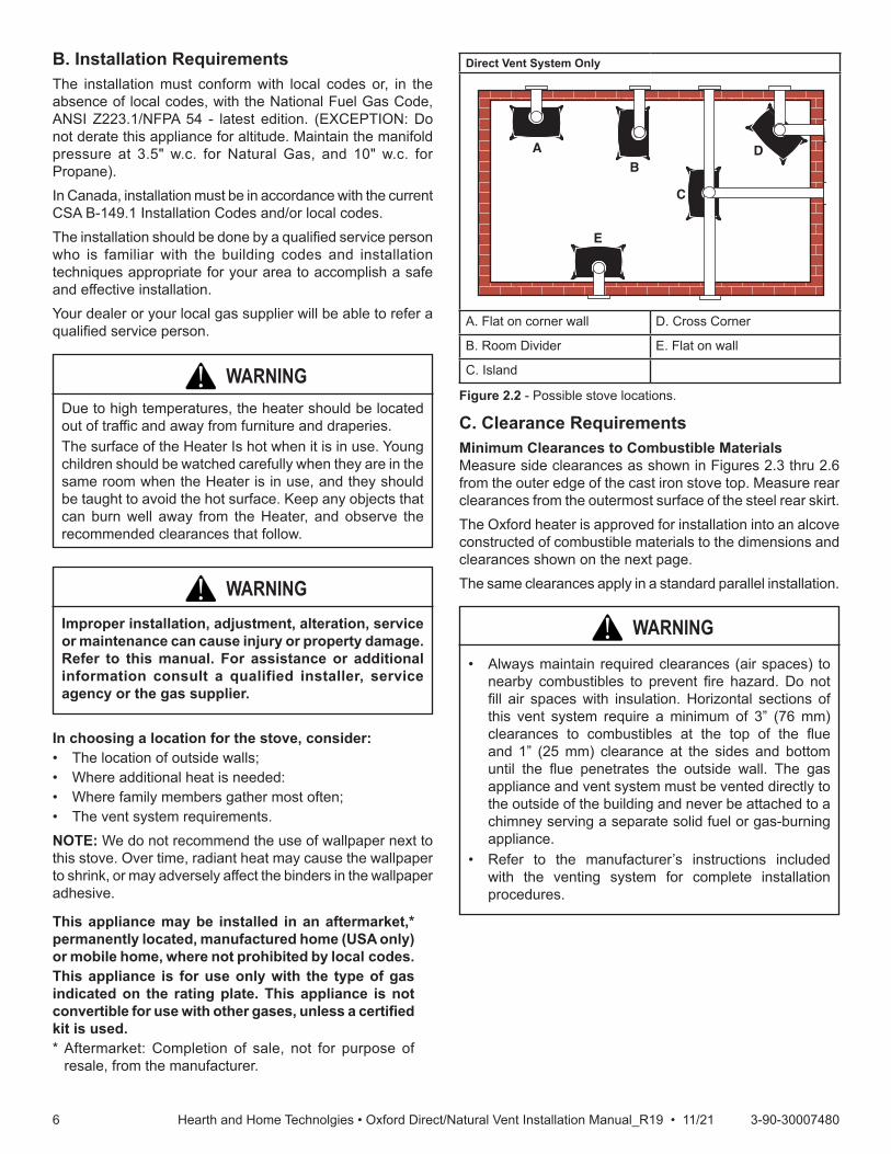
B. Installation RequirementsThe installation must conform with local codes or, in the absence of local codes, with the National Fuel Gas Code, ANSI Z223.1/NFPA 54 - latest edition. (EXCEPTION: Do not derate this appliance for altitude. Maintain the manifold pressure at 3.5" w.c. for Natural Gas, and 10" w.c. for Propane).In Canada, installation must be in accordance with the current CSA B-149.1 Installation Codes and/or local codes. The installation should be done by a qualified service person who is familiar with the building codes and installation techniques appropriate for your area to accomplish a safe and effective installation.Your dealer or your local gas supplier will be able to refer a qualified service person.
Figure 2.2 - Possible stove locations.
Direct Vent System Only
A. Flat on corner wall D. Cross Corner
B. Room Divider E. Flat on wall
C. Island
AB
E
C
D
ST207aStardanceStove locations9/28/00 djt
C. Clearance RequirementsMinimum Clearances to Combustible MaterialsMeasure side clearances as shown in Figures 2.3 thru 2.6 from the outer edge of the cast iron stove top. Measure rear clearances from the outermost surface of the steel rear skirt.The Oxford heater is approved for installation into an alcove constructed of combustible materials to the dimensions and clearances shown on the next page.The same clearances apply in a standard parallel installation.
In choosing a location for the stove, consider:• The location of outside walls;• Where additional heat is needed:• Where family members gather most often;• The vent system requirements. NOTE: We do not recommend the use of wallpaper next to this stove. Over time, radiant heat may cause the wallpaper to shrink, or may adversely affect the binders in the wallpaper adhesive.
WARNING!Due to high temperatures, the heater should be located out of traffic and away from furniture and draperies.The surface of the Heater Is hot when it is in use. Young children should be watched carefully when they are in the same room when the Heater is in use, and they should be taught to avoid the hot surface. Keep any objects that can burn well away from the Heater, and observe the recommended clearances that follow.
WARNING!• Always maintain required clearances (air spaces) to
nearby combustibles to prevent fire hazard. Do not fill air spaces with insulation. Horizontal sections of this vent system require a minimum of 3” (76 mm) clearances to combustibles at the top of the flue and 1” (25 mm) clearance at the sides and bottom until the flue penetrates the outside wall. The gas appliance and vent system must be vented directly to the outside of the building and never be attached to a chimney serving a separate solid fuel or gas-burning appliance.
• Refer to the manufacturer’s instructions included with the venting system for complete installation procedures.
Improper installation, adjustment, alteration, service or maintenance can cause injury or property damage. Refer to this manual. For assistance or additional information consult a qualified installer, service agency or the gas supplier.
WARNING!
This appliance may be installed in an aftermarket,* permanently located, manufactured home (USA only) or mobile home, where not prohibited by local codes.This appliance is for use only with the type of gas indicated on the rating plate. This appliance is not convertibleforusewithothergases,unlessacertifiedkit is used. * Aftermarket: Completion of sale, not for purpose of
resale, from the manufacturer.
77 3-90-30007480Hearth and Home Technolgies • Oxford Direct/Natural Vent Installation Manual_R19 • 11/21
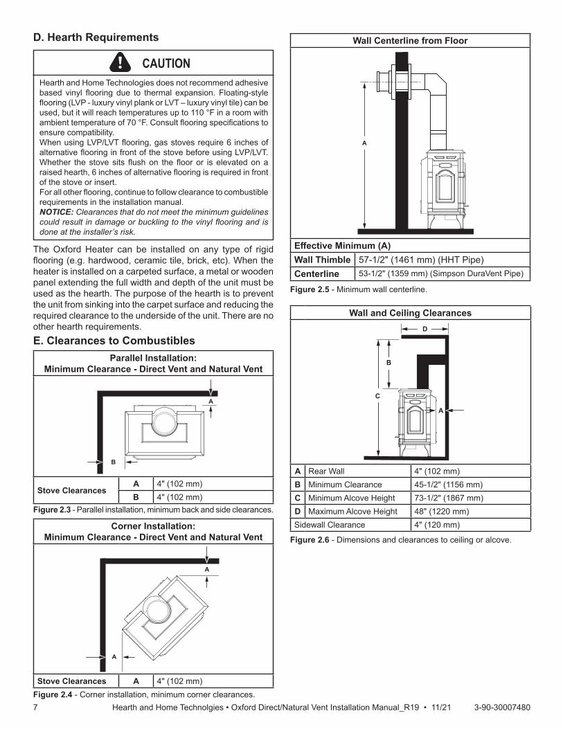
Figure 2.5 - Minimum wall centerline.
D. Hearth Requirements
Figure 2.4 - Corner installation, minimum corner clearances.
Corner Installation:Minimum Clearance - Direct Vent and Natural Vent
Stove Clearances A 4" (102 mm)ST129c
Dutchwestcorner specs
01/19
A
A
Figure 2.3 - Parallel installation, minimum back and side clearances.
Parallel Installation: Minimum Clearance - Direct Vent and Natural Vent
Stove ClearancesA 4" (102 mm)B 4" (102 mm)ST128b
Stardanceflue centerline
01/19
B
A
Wall Centerline from Floor
EffectiveMinimum(A)Wall Thimble 57-1/2" (1461 mm) (HHT Pipe)Centerline 53-1/2" (1359 mm) (Simpson DuraVent Pipe)
ST1121wall thimble
01/19
A
Figure 2.6 - Dimensions and clearances to ceiling or alcove.
Wall and Ceiling Clearances
A Rear Wall 4" (102 mm)B Minimum Clearance 45-1/2" (1156 mm)C Minimum Alcove Height 73-1/2" (1867 mm)D Maximum Alcove Height 48" (1220 mm)Sidewall Clearance 4" (120 mm)
A
C
D
ST1122Min. clearance
01/19
B
CAUTIONHearth and Home Technologies does not recommend adhesive based vinyl flooring due to thermal expansion. Floating-style flooring (LVP - luxury vinyl plank or LVT – luxury vinyl tile) can be used, but it will reach temperatures up to 110 °F in a room with ambient temperature of 70 °F. Consult flooring specifications to ensure compatibility.When using LVP/LVT flooring, gas stoves require 6 inches of alternative flooring in front of the stove before using LVP/LVT. Whether the stove sits flush on the floor or is elevated on a raised hearth, 6 inches of alternative flooring is required in front of the stove or insert.For all other flooring, continue to follow clearance to combustible requirements in the installation manual.NOTICE: Clearances that do not meet the minimum guidelines could result in damage or buckling to the vinyl flooring and is done at the installer’s risk.
The Oxford Heater can be installed on any type of rigid flooring (e.g. hardwood, ceramic tile, brick, etc). When the heater is installed on a carpeted surface, a metal or wooden panel extending the full width and depth of the unit must be used as the hearth. The purpose of the hearth is to prevent the unit from sinking into the carpet surface and reducing the required clearance to the underside of the unit. There are no other hearth requirements.E. Clearances to Combustibles

88 3-90-30007480Hearth and Home Technolgies • Oxford Direct/Natural Vent Installation Manual_R19 • 11/21
The installation of your Hearth and Home Technolo-gies stove must conform with local codes, or in the absence of local codes, with the National Fuel Gas Code ANSI Z223.1/NFPA 54 - latest edition, or CSA B149.1 Installation code. (EXCEPTION: Do not derate this appliance for altitude up to 2,000 (610 m) for natural gas and 4,500 feet (1,370 m) for Propane Gas. Maintain the manifold pressure at 3.5" w.c. for Natural Gas and 10.0" w.c. for Propane Gas.
HIGH ELEVATIONSInput ratings are shown in BTU per hour and are certifiedwithoutderationforelevationsupto2,000feet (610 m) for natural gas and 4,500 feet (1,370 m) for Propane gas above sea level.In the USA installations with elevations above 2,000 feet (610 m) for natural gas and 4,500 feet (1,370 m) for Propane gas must be in accordance with the current ANSI Z223.1/NFPA 54 and/or local codes having jurisdiction.In Canada, please consult provincial and/or local authorities having jurisdiction for installations at elevations above 2,000 feet (610 m) for natural gas and 4,500 feet (1,370 m) for Propane gas.
Horizontal Termination The vent must rise vertically a minimum of 24" (610 mm) off the top of the unit, before the first elbow. The horizontal run may extend up to 20’ (6m) and include a vertical rise of up to 40’ (12 m). (Figure 7) Horizontal termination must also meet the criteria shown in Figures 2.11 and 2.12.• Approved vent systems must terminate above and
including the heavy line in Figure 2.7.• Two 45° elbows may be substituted for each single 90°
elbow.• With a rise between 2’ - 5’, one 90° or two 45° elbows
may be used.
Figure 2.7 - Horizontal vent termination window.
Model Fuel Control
Max. Input BTU/h
Min. Input BTU/h
OXDV30SP NaturalGas
Millivolt Manual 28,000 20,000
OXDV30SP Propane Millivolt Manual 28,000 19,000
OXDV30IPI NaturalGas IPI 28,000 20,000
OXDV30IPI Propane IPI 28,000 19,000
Gas Inlet and Manifold PressuresNatural Liquid Propane
Inlet Minimum 5.0" w.c. 11.0" w.c.Inlet Maximum 14.0" w.c. 14.0" w.c.
Manifold Pressure 3.5" w.c. 10.0" w.c.
WARNING!Improper installation, adjustment, alteration, service or maintenance can cause injury or property damage. Refer to this manual for correct installation and operational pro-cedures. For assistance or additional information consult a qualified installer, service agency, or the gas supplier.
F.GasSpecifications G. Vent Terminations & Clearances
20
19
18
16
15
14
13
12
11
10
9
8
7
6
5
4
3
2
1
0
1 2 3 4 5 6 7 8 9 10 11 12 13 14 15 16 17 18 19 20
Verti
cal R
un (i
n fe
et)
(Mea
sure
d fro
m th
e ap
plia
nce
flue
colla
r to
the
top
of th
e ve
nt p
ipe.
)
Horizontal Run (in feet)
21
22
2324
25
26
27
28
29
30
3132
3334
35
36
3738
39
40
ST134bRadianceHorizontal vent run6/07
May use up to three 90° Elbows
One 90° Elbow
Unacceptable Venting Configuration
No Restrictor Plate Required

99 3-90-30007480Hearth and Home Technolgies • Oxford Direct/Natural Vent Installation Manual_R19 • 11/21
Examples for Extended Run/Restrictor Plate SettingsVertical 20’ (6 m), 90°
elbow, out 8’ (2.4 m)
Vertical 11’ (3.4 m), 90° elbow, out 2’
(610 mm)
Vertical 40’ (12 m)
Vertical 5’ (1.5 m), 90° elbow, out 5’
(1.5 m)
Restrictor plate measurement from top of plate to center of screw:233⁄44” (70 mm) from center of screw to top edge of
plate
Plate down to top of slot
Plate down to top of slot
233⁄88” (60 mm) from center of screw to top edge of
plate
Vertical TerminationA vertical vent system must terminate no less than 8’ (2.44 m) and no more than 40’ (12 m) above the appliance flue collar. (Refer to Figure 2.8) Adjust the restrictor plate according to recommendations in Figure 2.10. A vertically terminated vent system must also conform to the following criteria:• No more than three 90° elbows may be used.• Two 45° elbows may be substituted for one 90° elbow.
No more than six 45° elbows may be used.• Vent must rise a minimum of 2 feet (305 mm) before
offset is used.• Termination height must conform to roof clearance as
specified in Figure 2.8.
Restrictor Plate Adjustment for Extended Pipe RunsThe Oxford stove is shipped with a restrictor plate in the Parts Bag. Adjustments can be made by loosening the adjustment screw to allow the restrictor plate to slide up or down. (Figure 2.9) A guide for usage is shown in Figure 2.10.NOTE: Some installations may require some adjustment by the installer for optimum flame appearance. Optimum flame appearance is a flame that is not subject to tall, dirty yellow flames producing soot or flames lifting off of the ember bed ports.Restrictor Plate Adjustment• Remove the screw in the back wall of the firebox.• Install restrictor plate as shown in Figure 2.9 with cut out
on left side. Secure with adjustment screw.• Measure from center of screw to top edge of diverter
(Figure 2.9) to adjust plate according to guidelines in Figure 2.10.
• Tighten attachment screw.• Install logs following log installation instructions.
Figure 2.10
ST917restrictor plate6/07
Adjustment Screw
Figure 2.9 - Loosen screw to adjust restrictor plate.
Figure 2.8 - Vertical vent termination window.
20
19
18
16
15
14
13
12
11
10
9
8
7
6
5
4
3
2
1
0
201 2 3 4 5 6 7 8 9 10 11 12 13 14 15 16 17 18 19
Vert
ical
Run
(in
feet
)(M
easu
re fr
om th
e ap
plia
nce
flue
colla
r to
the
top
of th
e ve
nt p
ipe.
)
Horizontal Run (in feet)
21
22
2324
25
26
27
28
29
30
31
32
33
34
35
36
37
38
39
40
ST132aFDV28Vertical vent run12/3/99 djtareamodified1/11/00 djt
All Vertical Termi-nations in this area Require use of the 21⁄4" Restrictor Plate*
Vertical terminations must be within this area
Unacceptable Venting ConfigurationNo Restr
ictor P
late

1010 3-90-30007480Hearth and Home Technolgies • Oxford Direct/Natural Vent Installation Manual_R19 • 11/21
Your stove is approved to be vented either through the side wall, or vertical through the roof.• HHT does not require any opening for inspection of vent
pipe.• Only HHT SLP venting components or DuraVent venting
components specifically approved and labeled for this stove may be used.
• Maintain minimum clearances between vent pipes and combustible materials.
• Venting terminals shall not be recessed into a wall or siding.
• Any horizontal run must have a 1/4” rise for every one (1) foot of run towards the vent termination. Never run the vent level or down.
There must not be any obstruction such as bushes, garden sheds, fences, decks or utility buildings within 24" from the front of the termination hood.Do not locate termination hood where excessive snow or ice build up may occur. Be sure to check vent termination area after snow falls, and clear to prevent accidental blockage of venting system. When using snow blowers, make sure snow is not directed towards vent termination area.Location of Vent Termination It is imperative the vent termination be located observing the minimum clearances as shown in this manual.
Vent Termination ClearancesWhen planning the installation, consider the location of the vent terminal and clearances. Some of the most common clearances to keep in mind are shown in Figure 2.11. Important: All vent clearances must be maintained. Check your vent termination clearances against Figures 2.11 and 2.12.The vent should be placed so that people cannot be burned by accidentally touching the vent surfaces when the stove is operating.The vent termination should be located where it cannot be damaged by such things as automobile doors, lawn mowers or snowblowers and it should be located away from areas where it could become blocked by snow, etc.Some considerations are:• Obstructions or impediments to venting.• Nearby combustible materials that could come into
contact with combustion exhaust gases.• Other nearby openings {within 12" (305 mm)} through
which exhaust gas could reenter the building.• All vegetation within 3’ (76 mm) that may interfere with
the draft.Other factors that influence where the installation will be sited include the location of outside walls, where additional heat may be desired in the home, where the family members gather most regularly, and perhaps most importantly, the distance limitations of the venting system.IMPORTANTThe horizontal termination must not be recessed into the exterior wall or siding.Horizontal vent runs must be level toward the vent termination.Clearances around the vent termination must be maintained.For installations using DuraVent pipe, parallel installations with minimum wall clearance have restricted access for connecting the Horizontal Vent Cap straps to the vent pipe. See the maker’s instructions for recommended installation procedures.

1111 3-90-30007480Hearth and Home Technolgies • Oxford Direct/Natural Vent Installation Manual_R19 • 11/21
H. Chimney Diagram
CANADIAN INSTALLATIONS1 US INSTALLATIONS2
A = Clearance above grade, veranda, porch, deck or balcony
12" (30cm) 12" (30cm)
B = Clearance to window or door that may be opened
6" (15cm) for appliances <10,000 BTU/h (3kW)
12" (30cm) for appliances >10,000 BTU/h (3kW) and <100,000 BTU/h (30kW)
36" (91cm) for appliances >100,000 BTU/h (30kW)
6" (15cm) for appliances <10,000 BTU/h (3kW)
9" (23cm) for appliances >10,000 BTU/h (3kW) and <50,000 BTU/h (15kW)
12" (30cm) for appliances >50,000 BTU/h (15kW)
C = Clearance to permanently closed window 12" (305mm) recommended to prevent window condensation
12" (305mm) recommended to prevent window condensation
D = Vertical clearance to ventilated soffit located above the terminal within a horizontal distance of 2' (610 mm) from the center line of the terminal
18" (458mm) 18" (458mm)
E = Clearance to unventilated soffit 12" (305mm) 12" (305mm)
F = Clearance to outside corner see next page see next page
G = Clearance to inside corner see next page see next page
H = Clearance to each inside of center line extended above meter/regulator assembly
3' (91cm) within a height of 15' (5m) above the meter/regulator assembly
3' (91cm) within a height of 15' (5m) above the meter/regulator assembly
I = Clearance to service regulator vent outlet 3' (91cm) 3' (91cm)
J = Clearance to non-mechanical air supply inlet to building or the combustion air inlet to any other appliance
6" (15cm) for appliances <10,000 BTU/h (3kW)
12" (30cm) for appliances >10,000 BTU/h (3kW) and <100,000 BTU/h (30kW)
36" (91cm) for appliances >100,000 BTU/h (30kW)
6" (15cm) for appliances <10,000 BTU/h (3kW)
9" (23cm) for appliances >10,000 BTU/h (3kW) and <50,000 BTU/h (15kW)
12" (30cm) for appliances >50,000 BTU/h (15kW)
K = Clearance to mechanical air supply inlet 6' (1.83m) 3' (91cm) above if within 10' (3m) horizontally
L = Clearance above paved sidewalk or paved driveway located on public property
7' (2.13m)† 7' (2.13m)†
M = Clearance under veranda, porch, deck or balcony
12" (30cm)� 12" (30cm)�
N = Clearance above a roof shall extend a minimum of 24” (610mm) above the highest point when it passes through the roof surface, and any other obstruction within a horizontal distance of 18” (450mm).
V
V
V
V
V
V
V
X
X
X
D
E
B
B B
C
BM
B
A
JK
F
L
VENT TERMINATION AIR SUPPLY INLET AREA WHERE TERMINAL IS NOT PERMITTED
H
I
FixedClosed
OperableOperable
FixedClosed
VB
CFM145aDV Termin Location5/01/01 Rev. 12/05/01 sta
INSIDECORNER DETAIL
V
A
G
NN
CFM145a
Figure 2.11 - Vent termination clearances.
NOTE:1. Local codes or regulations may require different clearances.2. The special venting system used on Direct Vent Fireplaces are
certified as part of the appliance, with clearances tested and approved by the listing agency.
3. HHT assumes no responsibility for the improper performance of the appliance when the venting system does not meet these requirements.
1. In accordance with the current CSA-B149 Installation Codes2. In accordance with the current ANSI Z223.1/NFPA 54 National
Fuel Gas Codes† A vent shall not terminate directly above a sidewalk or paved
driveway which is located between two single family dwellings and serves both dwellings
� Only permitted if veranda, porch, deck or balcony is fully open on a minimum 2 sides beneath the floor.
1212 3-90-30007480Hearth and Home Technolgies • Oxford Direct/Natural Vent Installation Manual_R19 • 11/21
Figure 2.12 - Termination clearances.
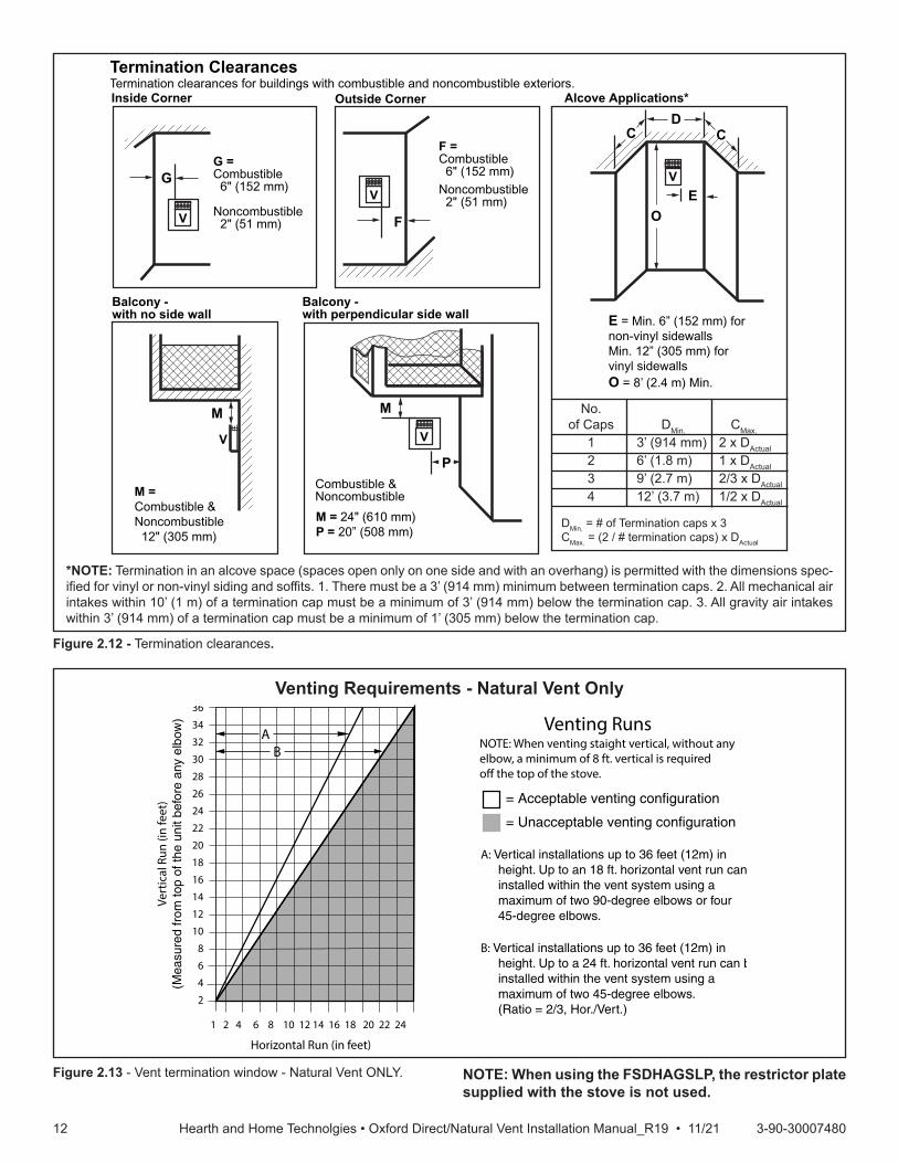
Venting Requirements - Natural Vent Only
FP567NVBR/NVBC VENTING RUNS11/12/97
Venting Runs
Horizontal Run (in feet)
Vert
ical
Run
(in
feet
)(M
easu
red
from
top
of th
e un
it be
fore
any
elb
ow)
A: Vertical installations up to 36 feet (12m) in height. Up to an 18 ft. horizontal vent run can be installed within the vent system using a maximum of two 90-degree elbows or four 45-degree elbows.
B: Vertical installations up to 36 feet (12m) in height. Up to a 24 ft. horizontal vent run can be installed within the vent system using a maximum of two 45-degree elbows. (Ratio = 2/3, Hor./Vert.)
= Acceptable venting configuration
= Unacceptable venting configuration
36
34
32
30
28
26
24
22
20
18
16
14
12
10
8
6
4
2
1 2 4 6 8 10 12 14 16 18 20 22 24
AB
NOTE: When venting staight vertical, without anyelbow, a minimum of 8 ft. vertical is requiredo� the top of the stove.
Figure 2.13 - Vent termination window - Natural Vent ONLY. NOTE: When using the FSDHAGSLP, the restrictor plate supplied with the stove is not used.
Outside CornerInside Corner
Termination ClearancesTermination clearances for buildings with combustible and noncombustible exteriors.
G =Combustible 6" (152 mm)
Noncombustible 2" (51 mm)
F =Combustible 6" (152 mm) Noncombustible 2" (51 mm)
G
Balcony - with no side wall
M = Combustible &Noncombustible 12" (305 mm)
M
Balcony - with perpendicular side wall
M = 24" (610 mm)P = 20” (508 mm)
M
F
Alcove Applications*
CD
C
E
V
V
Combustible &Noncombustible
V
V
V
E = Min. 6” (152 mm) for non-vinyl sidewallsMin. 12” (305 mm) forvinyl sidewallsO = 8’ (2.4 m) Min.
O
P
No. of Caps DMin. CMax.
1 3’ (914 mm) 2 x DActual
2 6’ (1.8 m) 1 x DActual
3 9’ (2.7 m) 2/3 x DActual
4 12’ (3.7 m) 1/2 x DActual
DMin. = # of Termination caps x 3CMax. = (2 / # termination caps) x DActual
*NOTE: Termination in an alcove space (spaces open only on one side and with an overhang) is permitted with the dimensions spec-ified for vinyl or non-vinyl siding and soffits. 1. There must be a 3’ (914 mm) minimum between termination caps. 2. All mechanical air intakes within 10’ (1 m) of a termination cap must be a minimum of 3’ (914 mm) below the termination cap. 3. All gravity air intakes within 3’ (914 mm) of a termination cap must be a minimum of 1’ (305 mm) below the termination cap.

1313 3-90-30007480Hearth and Home Technolgies • Oxford Direct/Natural Vent Installation Manual_R19 • 11/21
DuraVent Components
Starter Pipe Assembly (incl. inner & outer sections) 46DVA-ADP
90° Elbow, Blk. 46DVA-E90B*45° Elbow, Gal. 46DVA-E456" Straight, Blk. 46DVA-06B*9" Straight, Blk. 46DVA-09B11" - 14-5/8" Adjustable Straight Section 46DVA-08AB12" Straight 46DVA-1224" Straight 46DVA-24B*36" Straight 46DVA-36B48" Straight 46DVA-48Horizontal Vent Cap 46DVA-HC*Wall Plate 46DVA-DCVinyl Siding Shield 46DVA-VSSSnorkel Termination - 14" 46DVA-SNK14Snorkel Termination - 36" 46DVA-SNK30Wall Strap 46DVA-WSCathedral Ceiling Support Box 46DVA-CSStorm Collar 46DVA-SCFirestop Spacer 46DVA-FSFlashing 0/12 - 6/12 46DVA-F6Flashing 6/12 - 12/12 46DVA-F12Wall Thimble 46DVA-WTWall Thimble Cover (Brass) 3PVP-TKVWall Firestop 46DVA-WFSAttic Insulation Shield 46DVA-ISCo-Linear Vent Adapter 46DVA-GCLSteel Chimney Conv. Kit A (6-5/8" - 8-5/8") 46DVA-KCASteel Chimney Conv. Kit B (6-5/8" - 10-1/2") 46DVA-KCBSteel Chimney Conv. Kit C (6-5/8" - 13") 46DVA-KCCMasonry Chimney Conversion Kit 46DVA-KMCVertical Termination Cap (High Wind) 46DVA-VCHVertical Termination Cap (Low Profile) 46DVA-VC
SLP Horizontal Termination Kit (Termination Cap, SLP24-BK, SLP6-BK, SLP6A-BK, SLP90-BK, SLP-WT-BK & CCSLP)
SLP-SK-BK
Stove Adapter Kit (Includes 30' of 4" Flex, adapters, wall thimble, masonry and ZC flashing, 991DA Cap and Fasteners
LINK-STOVE
Trapezoid Termination Kit (3-1/8” - 4-3/4”) SLP-TRAP1Trapezoid Termination Kit (5-1/4” - 9-1/4”) SLP-TRAP2Rear Vent Termination Kit SLP-RVTKVertical Termination cap - High Wind (includes storm collar) SLP-TVHW
Decorative Wall Thimble Cover SLP-WT-BKDecorative ceiling firestop - black SLP-DCF-BKCathedral ceiling support - black SLP-CCS-BK4" (100mm) pipe length - black SLP4-BK6" (150mm) pipe length - black SLP6-BK12" Pipe length-black SLP12-BK24" Pipe length-black SLP24-BK36" (915mm) pipe length - black SLP36-BK48" Pipe length-black SLP48-BK3" - 6" (75 - 150mm) telescoping pipe extension - black SLP6A-BK
3" - 12" telescoping pipe extension-black SLP12A-BK45 degree elbow-black SLP45-BK90 degree elbow-black SLP90-BKOxford, Stardance, Oxford SLP adapter CCSLPFreestanding Draft Hood Adapter FSDHAGSLPSL Snorkel Cap (Includes 1 pair of firestops) SLK-SNKD*CCSLP adapter is required when using HHT components.
A. Venting Requirements & OptionsApproved Vent System ComponentsThe Oxford Heater must be vented to the outdoors through an adjacent exterior wall or through the roof. The venting system must be comprised of the appropriate listed venting components specified on this page. These parts are available from DuraVent Corporation or your Hearth and Home Technologies Dealer.See Figure 2.4 for dimensions relevant to the standard minimum-vent kits.HHT Components*
All DuraVent Straight vent pipe sections have a net length 1-1/2” (37mm) less than the nominal dimension; i.e., a 6” (152 mm) Straight pipe section has an effective length of 4-1/2” (115 mm).
3 3 Assembly and Installation

1414 3-90-30007480Hearth and Home Technolgies • Oxford Direct/Natural Vent Installation Manual_R19 • 11/21
B. Assembling the Stove: Tools Required• Phillips screwdriver (stub)• Utility knife• Metal drill bit: size 28 (.140"/3.5mm)• Flat-blade screwdriver• Power drill• Reciprocating saw• 9/16" wrench• 1/2” WrenchParts Bag Contents:• Three (3) Vent Screws• Wood handle w/insert lifter (handle for operable door)• Restrictor Plate• 4" Starter pipe• Three (3) Phillips round-head bolts, 1/4"- 20 x 1/2"• One (1) Tube of Vent Gasket Cement• Owner’s Installation and Operating ManualUnpack StoveUsing the 1/2” wrench remove the (4) lag bolts installed through the shipping brackets and into the skid. Once the lag bolts are removed, remove the shipping brackets from around each leg leveler located at each leg with the 7/16” Wrench.
WARNING!Only the IPI appliance is equipped with a three-prong (grounded) plug for your protection against shock hazard and should be plugged directly into a properly grounded three-prong receptacle. Do not cut or remove the ground-ing prong from this plug.
C. Venting System Assembly
CAUTION!All HHT Direct Vent Stoves have been tested and approved to ANSI/CSA Standards and will operate safely when installed in accordance with this instruction manual. Read all instructions before starting installation, then follow these instructions carefully to maximize stove performance and safety. Report damaged parts to your dealer.
Important Safety InformationThe termination cap MUST be vented directly to the outside. The termination kit MUST NEVER be connected to a chimney flue(s) servicing a separate solid-fuel burning appliance or any other appliances.• Termination cap MUST NOT be recessed into a wall,
Figure 3.1.• The installation must conform with local codes or in the
absence of local codes, with the National Fuel Gas Code, ANSI Z223.1 (in the United States) or with the current installation code CSA B149 (in Canada).
WARNING!Always maintain minimum clearances around vent systems. Rear/Top Vent Vertical Side wall: Horizontal sections of this vent system require a minimum of 3” (76 mm) clearances to combustibles at the top of the flue and 1” (25 mm) clearance at the sides and bottom until the flue penetrates the outside wall. A minimum 1” clearance all around the flue is acceptable at this point of penetration. If vertical rise is 7-1/2 feet (2.3 m) or higher when top venting, the clearance to combustibles is 1” on all sides of the horizontal run. FOR VERTICAL RUNS ONLY, maintain a 1” (25 mm) minimum clearance to all sides. Do not pack the open air spaces around the stove or flue with insulation or other materials. Any horizontal run must have a 1/4” rise for every one (1) foot of run towards the vent termination. Never run the vent level or down.
WARNING!Failure to follow these instructions may create a possible fire hazard and will void the warranty.
WARNING!Any common venting of this gas appliance with other gas appliances is not allowed.

1515 3-90-30007480Hearth and Home Technolgies • Oxford Direct/Natural Vent Installation Manual_R19 • 11/21
Before You StartPlan your installation. Set the stove in place and survey how to best vent the unit. Select the appropriate termination kit and vent pipe for the installation. Read these instructions and the stove Owner’s Manual before beginning installation. After vent configuration has been decided, begin attaching pipe to unit.Items required for installation:Tools: Phillips screwdriver HammerSaw and/or saber saw LevelMeasuring Tape Electric drill and bitsPliers SquareBuilding Supplies:Framing materialsWall finishing materialsCaulking Material (noncombustible)
• These models are approved to use HHT direct vent pipe components, HHT termination kits and DuraVent components. No other venting system components may be used.
• Horizontal runs must be supported every 5 feet (1.5 m) using wall straps. Vertical runs must be supported every 8 feet (2.4 m) using wall straps. Slip wall straps loosely on to pipe. Attach straps to framing members using nails or screws. Tighten nut/bolt to secure pipe.
• The stove and venting system should be inspected before initial use and at least annually by a qualified field service person. Inspect the external vent cap on a regular basis to make sure that no debris is interfering with the airflow. Inspect entire venting system to ensure proper function.
Outside Wall
Finishing Material(Vinyl Siding, etc.)
Figure 3.1 - Termination cap on wall
General InformationThe Oxford is approved for installation only with the vent components listed under Section A “Venting Requirements & Options”. Follow the vent component instructions exactly.For U.S. installations: The venting system must conform with local codes and/or the current National Fuel Gas Code, ANSI Z223.1/NFPA 54.For Canadian installations: The venting system must conform to the current CSA B149.1 installation code.
Install the starter Pipe1. Attach the starter to the stove.2. Place a 3/8” bead of millpack caulk around the inside of
the cast starter collar. Insert the 6-5/8” outer adapter into the cast outer starting collar and press down firmly.
3. Install the CCSLP Outer Adapter Pipe.4. Place a 3/8” bead of millpack caulk around the 4”
crimped end of the starter collar on the stove. Attach the SLP pipe to the adapter, and secure by aligning adapter and pipe seams, pressing down firmly until pipe stops, and twisting to lock into place, Figure 3.2.
WARNING!Any horizontal run must have a 1/4” rise for every one (1) foot of run towards the vent termination. Never allow the vent pipe to run down. This could cause high temperatures and may present a fire hazard.
WARNING!Termination cap must be positioned so the embossed arrow is pointed up.

1616 3-90-30007480Hearth and Home Technolgies • Oxford Direct/Natural Vent Installation Manual_R19 • 11/21
Figure 3.2 - Attach inner assembly to flue collar.
SLP
CCSLP
Starter Pipe
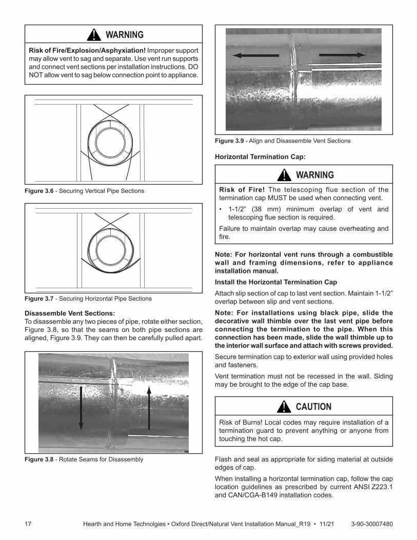
Assemble Slip SectionsThe outer flue of the slip section should slide over the outer flue of the pipe section and into (inner flue) the last pipe section, Figure 3.4.Slide together to the desired length, making sure that a 1-1/2” outer flue overlap is maintained between the pipe section and slip section. The pipe and slip section need to be secured by driving two 1/2 in. screws through the overlapping portions of the outer flues using the pilot holes, Figure 3.5. This will secure the slip section to the desired length and prevent it from separating. The slip section can then be attached to the next pipe section.If the slip section is too long, the inner and outer flues of the slip section can be cut to the desired length.
WARNING!Risk of Fire/Explosion! DO NOT break seals on slip sections. Use care when removing termination cap from slip pipe. If slip section seals are broken during removal of the termination cap, vent may leak.
Secure the Vent SectionsVertical sections of SLP pipe must be supported every 8 feet.The SLP firestop includes tabs that may be used to secure vertical sections.The vent support or plumber’s strap (spaced 120° apart) may be used to secure the vertical sections of pipe, Figure 3.6.Horizontal sections of vent must be supported every 5 feet with a vent support or plumber’s strap, Figure 3.7.
INCORRECTCORRECT
Figure 3.3 - Make sure the seams are not aligned to prevent unintentional disconnection.
Figure 3.4 - Slip Section Pilot Holes
Figure 3.5 - Screws into Slip Section
1717 3-90-30007480Hearth and Home Technolgies • Oxford Direct/Natural Vent Installation Manual_R19 • 11/21
WARNING!Risk of Fire/Explosion/Asphyxiation! Improper support may allow vent to sag and separate. Use vent run supports and connect vent sections per installation instructions. DO NOT allow vent to sag below connection point to appliance.
Figure 3.6 - Securing Vertical Pipe Sections
Figure 3.7 - Securing Horizontal Pipe Sections
Disassemble Vent Sections:To disassemble any two pieces of pipe, rotate either section, Figure 3.8, so that the seams on both pipe sections are aligned, Figure 3.9. They can then be carefully pulled apart.
Figure 3.8 - Rotate Seams for Disassembly
Figure 3.9 - Align and Disassemble Vent Sections
Horizontal Termination Cap:
WARNING!Risk of Fire! The telescoping flue section of the termination cap MUST be used when connecting vent.• 1-1/2” (38 mm) minimum overlap of vent and
telescoping flue section is required.Failure to maintain overlap may cause overheating and fire.
Note: For horizontal vent runs through a combustible wall and framing dimensions, refer to appliance installation manual.Install the Horizontal Termination CapAttach slip section of cap to last vent section. Maintain 1-1/2” overlap between slip and vent sections.Note: For installations using black pipe, slide the decorative wall thimble over the last vent pipe before connecting the termination to the pipe. When this connection has been made, slide the wall thimble up to the interior wall surface and attach with screws provided.Secure termination cap to exterior wall using provided holes and fasteners.Vent termination must not be recessed in the wall. Siding may be brought to the edge of the cap base.
Flash and seal as appropriate for siding material at outside edges of cap.When installing a horizontal termination cap, follow the cap location guidelines as prescribed by current ANSI Z223.1 and CAN/CGA-B149 installation codes.
CAUTION!Risk of Burns! Local codes may require installation of a termination guard to prevent anything or anyone from touching the hot cap.

1818 3-90-30007480Hearth and Home Technolgies • Oxford Direct/Natural Vent Installation Manual_R19 • 11/21
DivertRoofRun-offHHT recommends, where excessive water run-off is possible, use of one of the two options shown in Figure 3.10 to prevent water running off the roof and onto/into the horizontal termination cap.
4. Using appropriate length of pipe section(s) attach to stove by twisting collar.
5. Measure the horizontal length requirement including a 2” (51 mm) overlap, i.e. from the elbow to the outside wall face plus 2” (51 mm) (or the distance required if installing a second 90° elbow), Figure 3.13.
NOTE: Always install vertical side wall horizontal venting with a 1/4” rise for every 12” of run.
2. Secure firestop to the inside frame, center in the 9" x 9" vent opening.
3. Place stove into position. Measure the vertical height (X) required from the base of the flue collars to the center of the wall opening, Figure 3.12
Vertical Side Wall Installation:NOTE: Refer to Figures 2.8 thru 2.10 for restrictor plate adjustments for vertical vent runs. 1. Locate vent opening on the wall. It may be necessary
to first position the stove and measure to obtain hole location. Depending on whether the wall is combustible or noncombustible, cut opening to size, Figure 3.11 (For combustible walls first frame in opening.) Combustible Walls: Cut a 9" H x 9" W (244 x 244 mm) hole through the exterior wall and frame as shown, Figure 30. Noncombustible Walls: Hole opening must be 7" (178 mm) in diameter.NOTE:Whenusingflexvent,theopeningwillhavetobe measured according to the 1/2” (13 mm) rise in 12” (305 mm) vent run.
Install gutter
Install L-shaped diverter
Figure 3.10 - Locate Vent Opening on Wall
Vent Opening for Combustible Walls
VO584-100Vent Opening2/99 djt
Stove Hearth Framing Detail
Opening for Noncombustible Wall
7"(190 mm)
Stove Hearth
9"(244 mm)
9"(244 mm)
Figure 3.11 - Locate Vent Opening on Wall
X
Figure 3.12 - Vertical Height Requirements

1919 3-90-30007480Hearth and Home Technolgies • Oxford Direct/Natural Vent Installation Manual_R19 • 11/21
NOTE: Support horizontal pipes every 5' (152 cm) with metal pipe straps.
Vent Termination Below Grade:Install Snorkel Kit #SLP-SNORK when it is not possible to meet the required vent termination clearances of 12" (305 mm) above grade level. The snorkel kit will allow installation depth of down to 7" (178 mm) below grade level. The seven inches is measured from the center of the horizontal vent pipe as it penetrates the wall. If the venting system is installed below grade, a window well must be installed with adequate and proper drainage.NOTE: Be sure to maintain side wall clearances and vent run restrictions. Refer to Figures 2.3 thru 2.6.1. Establish the vent hole through the wall.2. Remove soil to a depth of approximately 16" (406 mm)
below the base of the snorkel. Install a window well (not supplied). Refill the hole with 12" (305 mm) of coarse gravel and maintain a clearance of at least 4" (102 mm) below the snorkel, Figure 3.16.
3. Install the vent system as described in Figures 3.2 thru 3.9.
4. Be sure to make a watertight joint around the vent pipe joint at the inside and outside wall joints.
5. Apply high temperature sealant around the inner and outer snorkel collars. Join the pipes and fasten the snorkel termination to the wall with the screws provided.
6. Level the soil to maintain a 4" clearance below the snorkel.
7. If the foundation is recessed, use extension brackets (not supplied) to fasten the lower portion of the snorkel. Fasten the brackets to the wall first, and then fasten to the snorkel with self-tapping #8 x 1/2" sheet metal screws. Extend the vent pipes out as far as the protruding wall face, Figure 3.15.
6. Use appropriate length of pipe sections – telescopic or fixed – and install. The sections which go through the wall are packaged with the starter kit, and can be cut to suit if necessary.
7. Guide the vent terminations 4" and 6-5/8” collars into their respective vent pipes. Double check that the vent pipes overlap the collars by 1-1/2" (38 mm). Secure the termination to the wall with screws provided and caulk around the wall plate to weatherproof. As an alternative to screwing the termination directly to the wall, you may also use expanding plugs or an approved exterior construction adhesive.
X
Figure 3.13 - Horizontal Length Requirement
KT1498cap on sidingT
Cutout On Vinyl
Vinyl Siding Wall
Termination Cap
Figure 3.14 - Horizontal Termination Cap on a Vinyl Siding Wall
Figure 3.15 - Use extension brackets to mount snorkel against recessed wall.
ST219snorkel detail12/6/99 djt
Recessed Wall
Sheet Metal Screws and Bracket
Wall Screws and Anchors
Waterproof Seal Around Pipe
Firestop
Finishing Collar
7" Pipe
Wall Plate
2020 3-90-30007480Hearth and Home Technolgies • Oxford Direct/Natural Vent Installation Manual_R19 • 11/21
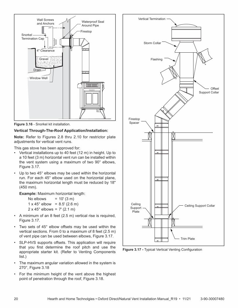
Vertical Through-The-Roof Application/Installation:Note: Refer to Figures 2.8 thru 2.10 for restrictor plate adjustments for vertical vent runs.This gas stove has been approved for:• Vertical installations up to 40 feet (12 m) in height. Up to
a 10 feet (3 m) horizontal vent run can be installed within the vent system using a maximum of two 90° elbows, Figure 3.17.
• Up to two 45° elbows may be used within the horizontal run. For each 45° elbow used on the horizontal plane, the maximum horizontal length must be reduced by 18" (450 mm).
Example: Maximum horizontal length: No elbows = 10' (3 m) 1 x 45° elbow = 8.5' (2.6 m) 2 x 45° elbows = 7' (2.1 m)• A minimum of an 8 feet (2.5 m) vertical rise is required,
Figure 3.17.• Two sets of 45° elbow offsets may be used within the
vertical sections. From 0 to a maximum of 8 feet (2.5 m) of vent pipe can be used between elbows, Figure 3.17.
• SLP-HVS supports offsets. This application will require that you first determine the roof pitch and use the appropriate starter kit. (Refer to Venting Components list.)
• The maximum angular variation allowed in the system is 270°, Figure 3.18
• For the minimum height of the vent above the highest point of penetration through the roof, Figure 3.18.
ST653install snorkel
04/19 ts
RADIANCE
Waterproof Seal Around Pipe
Firestop
Window Well
Drain
4" Clearance
Snorkel Termination Cap
Wall Screws and Anchors
Gravel
Figure 3.16 - Snorkel kit installation.
Figure 3.17 - Typical Vertical Venting Configuration
ST933Selkirk vertical venting6/07
Ceiling Support CollarCeiling Support
Plate
Trim Plate
Firestop Spacer
Offset Support Collar
Flashing
Storm Collar
Vertical Termination

2121 3-90-30007480Hearth and Home Technolgies • Oxford Direct/Natural Vent Installation Manual_R19 • 11/21
Roof Pitch H (Min.) Ft. Roof Pitch H (Min.) Ft.Flat to 6/12 1.0* Over 11/12 to 12/12 4.0
Over 6/12 to 7/12 1.25* Over 12/12 to 14/12 5.0
Over 7/12 to 8/12 1.5* Over 14/12 to 16/12 6.0
Over 8/12 to 9/12 2.0* Over 16/12 to 18/12 7.0
Over 9/12 to 10/12 2.5 Over 18/12 to 20/12 7.5
Over 10/12 to 11/12 3.25 Over 20/12 to 21/12 8.0
* 3 Feet. Minimum in Snow Regions
Horizontaloverhang
12X
20 in.(508 mm)
LowestDischargeOpening
TerminationCap
Roof Pitchis X / 12
Verticalwall
H (min.) - Minimum heightfrom roof to lowestdischarge opening.
24 in. min.(610 mm)
Roof Pitch H (Min.) Ft. Roof Pitch H (Min.) Ft.Flat to 6/12 1.0* Over 11/12 to 12/12 4.0Over 6/12 to 7/12 1.25* Over 12/12 to 14/12 5.0Over 7/12 to 8/12 1.5* Over 14/12 to 16/12 6.0Over 8/12 to 9/12 2.0* Over 16/12 to 18/12 7.0Over 9/12 to 10/12 2.5 Over 18/12 to 20/12 7.5Over 10/12 to 11/12 3.25 Over 20/12 to 21/12 8.0
* 3 ft. minimum in snow regions
Storm Collar
RoofFlashing
Figure 3.18 - Minimum Height from Roof to Lowest Discharge Opening
ST358DWDecorativepipe around b-vent5/15/03 djt
Decorative 7” Pipe
4” B-vent Pipe
Draft Hood Adapter
HHT Direct Vent System may be used from Draft Hood up to the ceiling
Figure 3.19 - Decorative 7” pipe may be fitted around the B-vent pipe.
The stove, when installed as a Natural vent heater, includes a vent safety switch. Operating the stove when it is not connected to a properly installed and maintained venting system, or tampering with or disconnecting the vent safety switch, can result in carbon monoxide (CO) poisoning and possible death.For U.S. installations: The venting system must conform with local codes and/or the current National Fuel Gas Code, ANSI Z22.1.For Canadian installations: The venting system must conform to the current CSA B149.1 installation code.Install the Vent PipeApply a bead of sealant around bottom end of inner starter pipe (found in bag with logset) and attach to stove. Apply a bead of sealant around top of inner starter pipe and install the FSDHAGSLP Draft Hood according to Draft Hood instructions, Figure 3.20.Attach the first section of venting to the draft hood. Depending on the length of the individual venting sections and the lengths of the decorative pipe (if installed), you may need to slip the decorative pipe over the venting sections before attaching upper sections to lower ones. The sections of decorative pipe should be oriented with their seams (if any) toward the wall; sections usually do not need to be fastened at each joint, other than slip sections. If the layout includes a slip section, this should be the last section of pipe visible in the room, at the ceiling. Complete the venting according to the vent maker’s instructions.
Venting System Assembly - Natural VentGeneral InformationThe heater is shipped from the factory as a Direct Vent Heater. It may be converted to a Natural Vent heater by installing the Model FSDHAGSLP Draft Hood Adapter.The heater is approved for installation as a Natural Vent. Hearth & Home Technologies Direct Vent pipe could be used directly after the Draft Hood Adapter up to the ceiling, then B-vent pipe must be used. Do not mix types of B-vent pipe; use components from one maker or the other. Follow the vent component maker’s instructions exactly. The heater will also accept standard or enameled 7” (150 mm) diameter pipe, around the Type B venting, for decorative purposes only, Figure 3.19.NOTE: The restrictor plate supplied with the stove is not used for Natural Vent applications.

2222 3-90-30007480Hearth and Home Technolgies • Oxford Direct/Natural Vent Installation Manual_R19 • 11/21
ST767DWattach draft hood5/15/03 djt
CEMENT
Figure 3.20 - Install draft hood adapter.
Class A Metal ChimneyPrior to installing the gas stove, ensure that the existing chimney is functionally sound and clean.• Have the chimney and adjacent structure inspected
and cleaned by qualified professionals. Hearth & Home Technologies recommends that NFI or CSIA certified professionals, or technicians under the direction of certified professionals, conduct a minimum of a NFPA 211 Level 2 inspection of the chimney.
• Replace component parts of the chimney and fireplace as specified by the professionals.
1. Remove existing chimney cap.2. Measure the distance from the top of the chimney to the
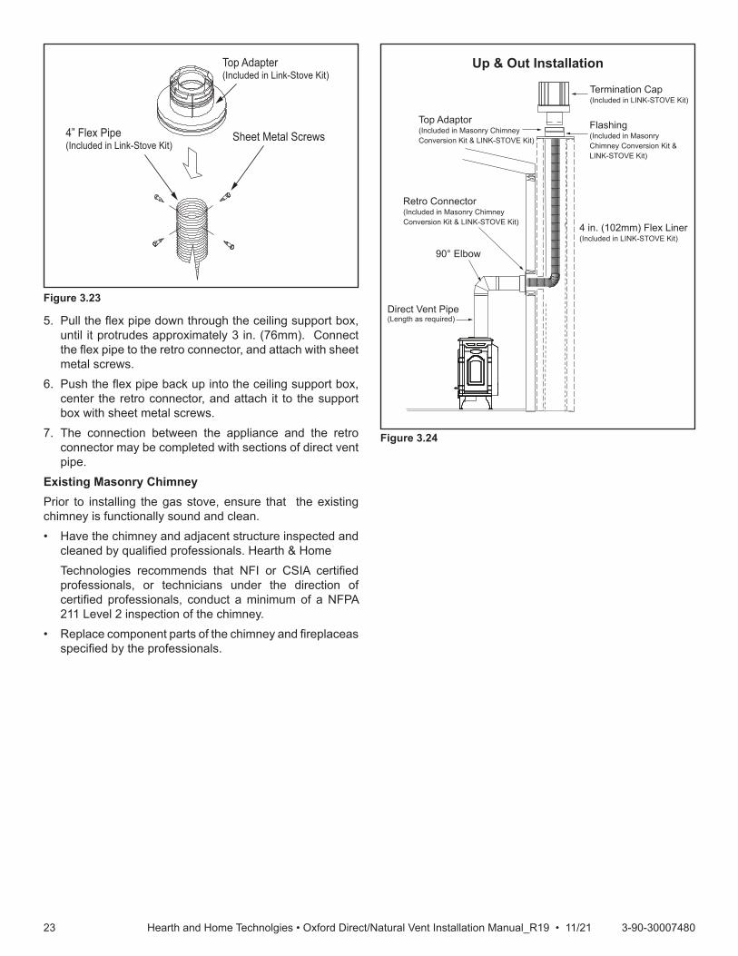
bottom of the ceiling support box, add 3 in. (76mm) to this measurement, and cut a section of 4 in. (101mm) flex pipe to that length (the flex should be fully extended).
3. Connect the end of the flex pipe section to the underside of the top adapter, using four sheet metal screws. See Figure 3.21.
4. Pass the flex pipe down through the center of the chimney system, and center the top adapter on the top of the chimney pipe. Drill four 1/8 in. (3mm) diameter holes through the top adapter, and into the chimney top. Ensure that you are drilling into the metal on the chimney. Twist lock the high wind termination cap onto the top adapter. See Figure 3.22 and Figure 3.23.
Top Adapter(Included in Link-Stove Kit)
Sheet Metal Screws4” Flex Pipe(Included in Link-Stove Kit)
Figure 3.21
Termination Cap(Includ. in Link-Stove Kit)
Existing Metal Chimney System
Top Adaptor(Includ. in Link-Stove Kit)
Direct Vent Pipe(Length as required)
Flashing(Includ. in Link-Stove Kit)
4 in. (102mm) Flex Pipe(Includ. in Link-Stove Kit)
Retro Connector(Includ. in Link-Stove Kit)
Figure 3.20
Figure 3.22
2323 3-90-30007480Hearth and Home Technolgies • Oxford Direct/Natural Vent Installation Manual_R19 • 11/21
5. Pull the flex pipe down through the ceiling support box, until it protrudes approximately 3 in. (76mm). Connect the flex pipe to the retro connector, and attach with sheet metal screws.
6. Push the flex pipe back up into the ceiling support box, center the retro connector, and attach it to the support box with sheet metal screws.
7. The connection between the appliance and the retro connector may be completed with sections of direct vent pipe.
Existing Masonry ChimneyPrior to installing the gas stove, ensure that the existing chimney is functionally sound and clean.• Have the chimney and adjacent structure inspected and
cleaned by qualified professionals. Hearth & Home Technologies recommends that NFI or CSIA certified
professionals, or technicians under the direction of certified professionals, conduct a minimum of a NFPA 211 Level 2 inspection of the chimney.
• Replace component parts of the chimney and fireplaceas specified by the professionals.
Top Adapter(Included in Link-Stove Kit)
Sheet Metal Screws4” Flex Pipe(Included in Link-Stove Kit)
Figure 3.23
Up & Out Installation
Termination Cap(Included in LINK-STOVE Kit)
Flashing(Included in Masonry Chimney Conversion Kit & LINK-STOVE Kit)
4 in. (102mm) Flex Liner (Included in LINK-STOVE Kit)
Top Adaptor(Included in Masonry Chimney Conversion Kit & LINK-STOVE Kit)
Retro Connector(Included in Masonry Chimney Conversion Kit & LINK-STOVE Kit)
90° Elbow
Direct Vent Pipe(Length as required)
Figure 3.24
2424 3-90-30007480Hearth and Home Technolgies • Oxford Direct/Natural Vent Installation Manual_R19 • 11/21
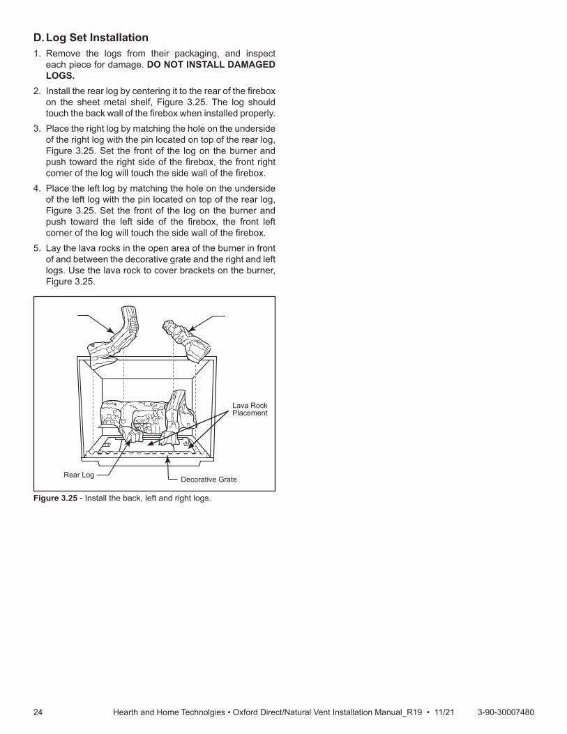
LG141StardanceInstall logs 112/11/00 djt
Rear Log Decorative Grate
Figure 3.25 - Install the back, left and right logs.
Lava Rock Placement
D. Log Set Installation1. Remove the logs from their packaging, and inspect
each piece for damage. DO NOT INSTALL DAMAGED LOGS.
2. Install the rear log by centering it to the rear of the firebox on the sheet metal shelf, Figure 3.25. The log should touch the back wall of the firebox when installed properly.
3. Place the right log by matching the hole on the underside of the right log with the pin located on top of the rear log, Figure 3.25. Set the front of the log on the burner and push toward the right side of the firebox, the front right corner of the log will touch the side wall of the firebox.
4. Place the left log by matching the hole on the underside of the left log with the pin located on top of the rear log, Figure 3.25. Set the front of the log on the burner and push toward the left side of the firebox, the front left corner of the log will touch the side wall of the firebox.
5. Lay the lava rocks in the open area of the burner in front of and between the decorative grate and the right and left logs. Use the lava rock to cover brackets on the burner, Figure 3.25.

2525 3-90-30007480Hearth and Home Technolgies • Oxford Direct/Natural Vent Installation Manual_R19 • 11/21
4 4 Gas Information
A. Fuel Conversion• Make sure the appliance is compatible with available gas
types.• Conversions must be made by a qualified technician
using Hearth & Home Technologies specified and approved parts.
B. Gas Pressure• Optimum appliance performance requires proper input
pressures.• Gas line sizing requirements will be determined in ANSI
Z221.3 National Fuel Gas Code in the USA and CAN/ CGA B149 in Canada.
• Pressure requirements are:
Gas Pressure Natural Gas PropaneMinimum Inlet Pressure 5.0 in. w.c. 11.0 in. w.c.Maximum Inlet Pressure 10.0 in. w.c. 13.0 in. w.c.Manifold Pressure 3.5 in. w.c. 10.0 in. w.c.
WARNING! Risk of Fire/Explosion! High pressure will damage valve. Low pressure may cause explosion.• Verify inlet pressures. Verify minimum pressures when
other household gas appliances are operating.• Install regulator upstream of valve if line pressure is
greater than 1/2 psig.
Note: Have the gas supply line installed in accordance with local codes, if any. If not, follow ANSI 223.1. Installation should be done by a qualified installer approved and/or licensed as required by the locality. (In the Commonwealth of Massachusetts installation must be performed by a licensed plumber or gas fitter).Note: A listed (and Commonwealth of Massachusetts approved) 1/2 inch (13 mm) T-handle manual shut-off valveand flexible gas connector are connected to the 1/2 inch (13 mm) control valve inlet.• If substituting for these components, please consult
local codes for compliance.
C. Gas Connection• Pipe incoming gas line into valve compartment.• Connect incoming gas line to the 1/2 in. (13 mm)
connection on manual shutoff valve.WARNING! Risk of Fire/Explosion! Support control when attaching pipe to prevent bending gas line.• A small amount of air will be in the gas supply lines.WARNING! Risk of Fire/Explosion! Gas build-up during line purge could ignite.• Purge should be performed by a qualified technician.• Ensure adequate ventilation.• Ensure there are no ignition sources such as sparks or
open flames.Light the appliance. It will take a short time for air to purge from lines. When purging is complete the appliance will light and operate normally.WARNING! Risk of Fire, Explosion or Asphyxiation! Check all fittings and connections with a non-corrosive commercially available leak-check solution. DO NOT use open flame. Fittings and connections could have loosened during shipping and handling.WARNING! Risk of Fire! DO NOT change valve settings. This valve has been preset at the factory.
D. High Altitude InstallationsNOTICE: If the heating value of the gas has been reduced, these rules do not apply. Check with your local gas utility or authorities having jurisdiction.When installing above 2000 feet elevation:• In the USA: Reduce burner orifice 4% for each 1000 feet
above 2000 feet.• In CANADA: Input ratings are certified without a
reduction of input rate for elevations up to 4500 feet (1370 m) above sea level. Please consult provincial and/or local authorities having jurisdiction for installations at elevations above 4500 feet (1370 m).
Fire Risk, Explosion Hazard.High pressure will damage valve.• Disconnect gas supply piping BEFORE
pressure testing gas line at test pressures above 1/2 psig.
• Close the manual shutoff valve BEFORE pressure testing gas line at test pressures equal to or less than 1/2 psig.
WARNING!

2626 3-90-30007480Hearth and Home Technolgies • Oxford Direct/Natural Vent Installation Manual_R19 • 11/21
E. Gas Supply Line ConnectionCheck the Rating Plate attached by a steel cable to the firebox, to confirm that you have the appropriate firebox for the type of fuel to be used. The Oxford may be converted from one gas to another using the appropriate Fuel Conversion Kit.
This appliance should only be connected by a qualified gas technician. Test to confirm manifoldpressuresasspecifiedbelow.Theheaterandits individualshutoffvalvemustbedisconnected from the gas supply piping during any pressure testing of that system at test pressures in excess of 1/2 psig (3.5 kPa).The heater must be isolated from the gas supply piping system by closing its individual manual shutoffvalveduringanypressuretestingofthegassupply piping system at test pressure equal to or less than 1/2 psig.Theremustbeagasshutoffbetweenthestoveandthe supply.In order to connectNaturalGas, use a fittingwith3/8” NPT nipple on the valve side and 1/2” natural gas supply line with an input of 28,000 BTUs at a manifold pressure of 3.5” and minimum inlet supply for adjustment of 5.5” w.c. InordertoconnectPropane,useafittingwith3/8”NPT nipple on the valve side and 1/2” propane gas supply line with an input of 28,000 BTUs at a manifold pressure of 10.0” and minimum inlet supply for adjustment of 11.0” w.c.
CAUTION!
In the U.S.; Gas connection should be made in accordance with current National Fuel Gas Code, ANSI Z223.1/NFPA 54. Since some municipalities have additional local codes, be sure to consult your local authority.In Canada; consult the local authority and CSA-B149.1 installation code.
Air Shutter AdjustmentThe Oxford is shipped from the factory with the air shutter adjusted to the minimum allowed opening. Refer to Table 1. Based on the altitude where the stove is located, a shutter adjustment is acceptable to provide a mixed balance of flame color/glow. To adjust the shutter opening, follow the steps below.NOTE: The air shutter may only be adjusted to a more open position. The factory setting is the minimum allowable air shutter opening, Figures 4.3 and 4.4.
Table 1. Air Shutter AdjustmentMinimum rear injector inlet openings.
Model Natural Gas PropaneDirect Vent 1/2" 1/2"
Natural Vent 1/2" 1"
Light the pilot according to the directions before going to the next step.
F. Burner InformationThe appliance must only use the gas specified on the rating plate, unless converted using a Fuel Conversion Kit. Conversion instructions are provided with each kit.
CAUTION!Always check for gas leaks with a mild soap and water solution. Do not use an open flame for leaktesting.
To adjust the air shutter, the following procedures should be followed:1. Remove barrier screen first by pulling out and up.
Remove stove front. Lift stove front up and then swing bottom out and away to disengage from the stove body, Figure 4.1.
2. Swing open the swiveling latches at the top left and right corners of the glass frame.
ST1125remove front
Figure 4.1 - Remove stove front.

2727 3-90-30007480Hearth and Home Technolgies • Oxford Direct/Natural Vent Installation Manual_R19 • 11/21
3. Pull the top edge of the glass and frame assembly away from the firebox, and lift it off its supports on the bottom of the firebox face. Place the assembly out of the way on a flat, padded surface such as a counter protected by a towel.
4. Take the logset out of the firebox if previously installed.5. Remove the rear log bracket by unfastening the screw,
Figure 4.2.6. Remove the right and left log bracket assembly by
unfastening the two screws which hold the burner in place, Figure 4.2.
7. Hold the burner at the right hand side and lift to clear the right burner leg. Then pull to the right to clear the injectors on the left hand side.
8. The air shutter is located on the bottom of the burner to the left, Figure 4.2. Unfasten the two nuts holding the shutter in place.
ST350Jeffersonair shutter adj3/20/00 djt
Remove Screws Rear Log Bracket
Pilot
Left & Right Log Bracket Assembly
Figure 4.2 - Remove rear log bracket and left and right log bracket assembly.
ST352jeffersonair shutternew position3/20/00 djt
Air Shutter(Original Position)
BurnerSee Table 1
Figure 4.3 - Air shutter in original from-the-factory position.
ST351jeffersonair shutteroriginal position3/20/00 djt
Front Injector Air Inlet Air Shutter
(May be adjusted up to fully open)
Burner
Rear Injector Air Inlet
Figure 4.4 - Air shutter adjusted.
9. Refasten the two nuts and assemble the burner into the unit by sliding the burner in at an angle with the left side lower than the right side. Slide the left side onto the injectors. Lower the right hand side down into place. Make sure the burner is as far left as possible and the injector shoulders are inside the burner. NOTE: It is very critical to keep the left burner leg, which holds the injectors, at a 90° angle to the base, Figure 45. This keeps the orifices aligned with tubes on the inside of the burner. Failure to do so could affect the flame appearance and performance of the unit.
10. Refasten the right and left log bracket assembly.11. Refasten the rear log bracket.12. Replace logs.13. Replace glass and stove front.Follow lighting instructions. Check flame color appearance. NOTE: Allow stove to burn for at least 1/2 hour to establish full flame color.Should color need further adjustment, repeat steps 1 - 12 for air shutter adjustment.
The shutter may be adjusted between the factory adjusted 1/2” to fully open. Reassemble the shutter to allow the rear injector air inlet to close from the minimum 1/2” opening to fully open, Figure 4.4. You may have to try more than once to find the correct air shutter opening for best results depending on your altitude.
ST353air shutter adjustburner replace3/20/00 djt
90°
Left Burner Leg
Injector Shoulder
Figure 4.5 - Be sure to maintain 90° angle at left burner leg.
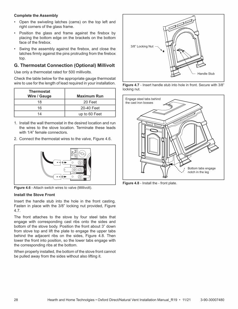
2828 3-90-30007480Hearth and Home Technolgies • Oxford Direct/Natural Vent Installation Manual_R19 • 11/21
Complete the Assembly• Open the swiveling latches (cams) on the top left and
right corners of the glass frame.• Position the glass and frame against the firebox by
placing the bottom edge on the brackets on the bottom face of the firebox.
• Swing the assembly against the firebox, and close the latches firmly against the pins protruding from the firebox top.
G. Thermostat Connection (Optional) MillivoltUse only a thermostat rated for 500 millivolts.Check the table below for the appropriate gauge thermostat wire to use for the length of lead required in your installation.
ThermostatWire / Gauge Maximum Run
18 20 Feet16 20-40 Feet14 up to 60 Feet
1. Install the wall thermostat in the desired location and run the wires to the stove location. Terminate these leads with 1/4” female connectors.
2. Connect the thermostat wires to the valve, Figure 4.6.
ST773handle assy6/6/03
3/8” Locking Nut
Handle Stub
Figure 4.7 - Insert handle stub into hole in front. Secure with 3/8” locking nut.
ST1126install stove front
Engage steel tabs behind the cast iron bosses
Bottom tabs engage notch in the leg
Figure 4.8 - Install the - front plate.
PILOT
ADJ
TPTH
TPTH
ST228attach switchwires to valve12/99
Figure 4.6 - Attach switch wires to valve (Millivolt).
Install the Stove FrontInsert the handle stub into the hole in the front casting. Fasten in place with the 3/8” locking nut provided, Figure 4.7.The front attaches to the stove by four steel tabs that engage with corresponding cast ribs onto the sides and bottom of the stove body. Position the front about 3” down from stove top and lift the plate to engage the upper tabs behind the adjacent ribs on the sides, Figure 4.8. Then lower the front into position, so the lower tabs engage with the corresponding ribs at the bottom.When properly installed, the bottom of the stove front cannot be pulled away from the sides without also lifting it.
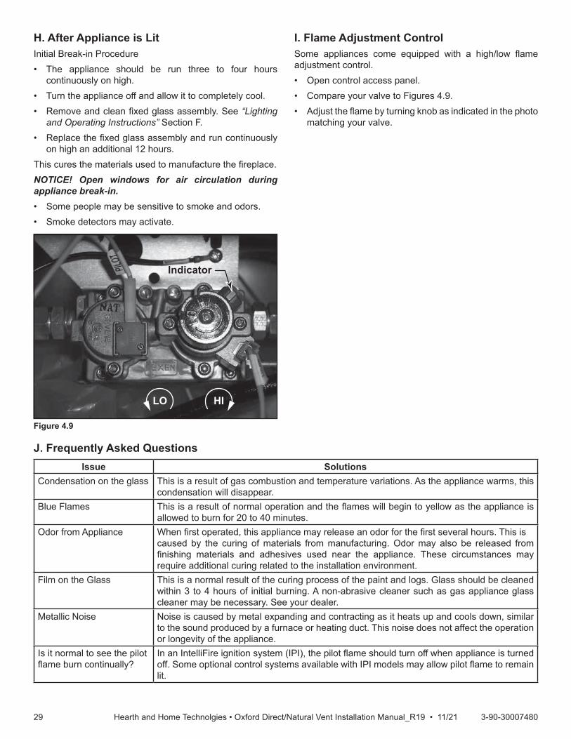
2929 3-90-30007480Hearth and Home Technolgies • Oxford Direct/Natural Vent Installation Manual_R19 • 11/21
H. After Appliance is LitInitial Break-in Procedure• The appliance should be run three to four hours
continuously on high.• Turn the appliance off and allow it to completely cool.• Remove and clean fixed glass assembly. See “Lighting
and Operating Instructions” Section F.• Replace the fixed glass assembly and run continuously
on high an additional 12 hours.This cures the materials used to manufacture the fireplace.NOTICE! Open windows for air circulation during appliance break-in.• Some people may be sensitive to smoke and odors.• Smoke detectors may activate.
I. Flame Adjustment ControlSome appliances come equipped with a high/low flame adjustment control.• Open control access panel.• Compare your valve to Figures 4.9.• Adjust the flame by turning knob as indicated in the photo
matching your valve.
HILO
Indicator
Figure 4.9
Issue SolutionsCondensation on the glass This is a result of gas combustion and temperature variations. As the appliance warms, this
condensation will disappear.Blue Flames This is a result of normal operation and the flames will begin to yellow as the appliance is
allowed to burn for 20 to 40 minutes.Odor from Appliance When first operated, this appliance may release an odor for the first several hours. This is
caused by the curing of materials from manufacturing. Odor may also be released from finishing materials and adhesives used near the appliance. These circumstances may require additional curing related to the installation environment.
Film on the Glass This is a normal result of the curing process of the paint and logs. Glass should be cleaned within 3 to 4 hours of initial burning. A non-abrasive cleaner such as gas appliance glass cleaner may be necessary. See your dealer.
Metallic Noise Noise is caused by metal expanding and contracting as it heats up and cools down, similar to the sound produced by a furnace or heating duct. This noise does not affect the operation or longevity of the appliance.
Is it normal to see the pilotflame burn continually?
In an IntelliFire ignition system (IPI), the pilot flame should turn off when appliance is turned off. Some optional control systems available with IPI models may allow pilot flame to remain lit.
J. Frequently Asked Questions
3030 3-90-30007480Hearth and Home Technolgies • Oxford Direct/Natural Vent Installation Manual_R19 • 11/21
5 5 Electrical Information
A. Wiring RequirementsNOTICE: This appliance must be electrically wired and grounded in accordance with local codes or, in the absence of local codes, with National Electric Code ANSI/NFPA 70-latest edition or the Canadian Electric Code CSA C22.1.• Wire the appliance junction box to 110-120 VAC. This is
required for proper operation of the appliance.• A 110-120 VAC circuit for this product must be protected
with ground-fault circuit-interrupter protection, in compliance with the applicable electrical codes, when it is installed in locations such as in bathrooms or near sinks.
• Low voltage and 110-120 VAC voltage cannot be shared within the same wall box.
WARNING! Risk of Shock or Explosion! DO NOT wire 110V to the valve or to the appliance wall switch. Incorrect wiring will damage controls.
B.IntellifireIgnitionSystemWiring• Wire the appliance junction box to 110-120 VAC for
proper operation of the appliance.WARNING! Risk of Shock or Explosion! DO NOT wire IPI controlled appliance junction box to a switched circuit. Incorrect wiring will override IPI safety lockout.• Refer to Figure 5.1, Intellifire Pilot Ignition (IPI) Wiring
Diagram.• This appliance is equipped with an Intellifire control valve
which operates on a 3-volt system.• Plug the 3-volt AC transformer into the appliance junction
box to supply power to the unit OR install two D cell batteries (not included) into the battery pack before use.
NOTICE: Batteries should not be placed in the battery packwhile using the transformer. Remove batteries before using the transformer, and unplug the transformer before installing the batteries. Battery polarity must be correct or module damage will occur.
C. Optional Accessories Requirements• This appliance may be used with a wall switch, wall
mounted thermostat and/or a remote control.Wiring for optional Hearth & Home Technologies approved accessories should be done now to avoid reconstruction. Follow instructions that come with those accessories.
D. Electrical Service and RepairWARNING! Risk of Shock! Label all wires prior to disconnection when servicing controls. Wiring errors can cause improper and dangerous operation. Verify proper operation after servicing.WARNING! Risk of Shock! Replace damaged wire with type 105° C rated wire. Wire must have high temperature insulation.
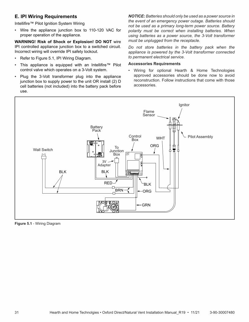
3131 3-90-30007480Hearth and Home Technolgies • Oxford Direct/Natural Vent Installation Manual_R19 • 11/21
Figure 5.1 - Wiring Diagram
E. IPI Wiring RequirementsIntellifire™ Pilot Ignition System Wiring• Wire the appliance junction box to 110-120 VAC for
proper operation of the appliance.WARNING! Risk of Shock or Explosion! DO NOT wire IPI controlled appliance junction box to a switched circuit. Incorrect wiring will override IPI safety lockout.• Refer to Figure 5.1, IPI Wiring Diagram.• This appliance is equipped with an Intellifire™ Pilot
control valve which operates on a 3-Volt system.• Plug the 3-Volt transformer plug into the appliance
junction box to supply power to the unit OR install (2) D cell batteries (not included) into the battery pack before use.
NOTICE: Batteries should only be used as a power source in the event of an emergency power outage. Batteries should not be used as a primary long-term power source. Battery polarity must be correct when installing batteries. When using batteries as a power source, the 3-Volt transformer must be unplugged from the receptacle.Do not store batteries in the battery pack when the appliance is powered by the 3-Volt transformer connected to permanent electrical service.Accessories Requirements• Wiring for optional Hearth & Home Technologies
approved accessories should be done now to avoid reconstruction. Follow instructions that come with those accessories.
3VAdapter
GRN
ORG
BLK
ORG
BLK
BRN
RED
BLK
Valve
WHT
BatteryPack
ToJunction
Box
ControlBox
Flame Sensor
Ignitor
Pilot Assembly
Wall Switch +
- +
-
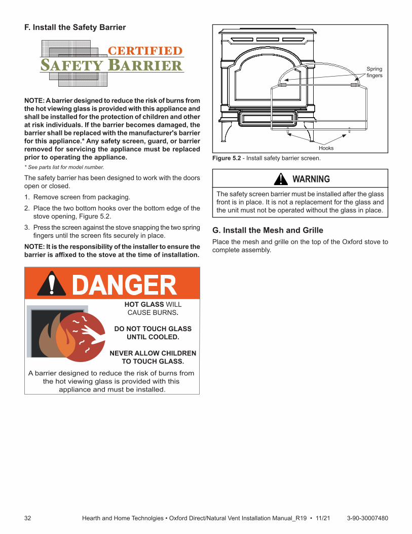
3232 3-90-30007480Hearth and Home Technolgies • Oxford Direct/Natural Vent Installation Manual_R19 • 11/21
G. Install the Mesh and GrillePlace the mesh and grille on the top of the Oxford stove to complete assembly.
NOTE: A barrier designed to reduce the risk of burns from the hot viewing glass is provided with this appliance and shall be installed for the protection of children and other at risk individuals. If the barrier becomes damaged, the barrier shall be replaced with the manufacturer's barrier for this appliance.* Any safety screen, guard, or barrier removed for servicing the appliance must be replaced prior to operating the appliance.* See parts list for model number.
The safety barrier has been designed to work with the doors open or closed. 1. Remove screen from packaging.2. Place the two bottom hooks over the bottom edge of the
stove opening, Figure 5.2.3. Press the screen against the stove snapping the two spring
fingers until the screen fits securely in place. NOTE: It is the responsibility of the installer to ensure the barrierisaffixedtothestoveatthetimeofinstallation.
CERTIFIEDSAFETY BARRIER
Figure 5.2 - Install safety barrier screen.
WARNING!The safety screen barrier must be installed after the glass front is in place. It is not a replacement for the glass and the unit must not be operated without the glass in place.
F. Install the Safety Barrier
Spring fingers
Hooks
DANGERHOT GLASS WILLCAUSE BURNS.
DO NOT TOUCH GLASSUNTIL COOLED.
NEVER ALLOW CHILDRENTO TOUCH GLASS.
A barrier designed to reduce the risk of burns from the hot viewing glass is provided with this
appliance and must be installed.

3333 3-90-30007480Hearth and Home Technolgies • Oxford Direct/Natural Vent Installation Manual_R19 • 11/21
A. OperationThe Oxford is to be operated with the front glass in place. Ensure the safety barrier screen is in place during operation.
B. Lighting InstructionsRead these instructions carefully and familiarize yourself with the lighting instructions. Section F, “Lighting and Operating Instructions”. Locate the pilot assembly, Figure 6.1. Follow the lighting instructions in this manual exactly. During the first fire, it is not unusual to smell some odor associated with new logs, paint and metal being heated. Odors should dissipate within the first eight to ten hours, however, you can open a window to provide fresh air to alleviate the condition.
C. Pilot and Burner InspectionEach time you light your heater check that the pilot flame and burner flame patterns are as shown in Figure 6.2. If flame patterns are incorrect, turn the heater off. Contact your dealer or a qualified gas technician for assistance. Do not operate the heater until the pilot flame is correct.Follow regular maintenance procedures as described in the Cleaning and Maintenance section of this manual.
E. Flame & Temperature AdjustmentFor OXDV30 models which are equipped with HI/LO valves, flame adjustment is accomplished by rotating the HI/LO adjustment knob located near the center of the gas control valve, Figure 6.3.
D. Flame CharacteristicsIt is important to periodically perform a visual check of the pilot and the burner flames. Compare them to Figure 6.2. If any of the flames appear abnormal, call a service person.
Figure 6.2 - Correct pilot and burner flame appearance.
Figure 6.3 - Flame adjustment knob
LO
HI
FP390FLAME ADJUSTMENT KNOB11/21/96
Turn counterclockwise
to increaseflame height
Turn clockwiseto decreaseflame height
6 6 Operating Instructions
ST769Dutchwestpilot location5/15/03 djt
Pilot Assembly
Figure 6.1 - Pilot assembly location.
LG142StardanceInstall logs 212/11/00 djt
Red Glow

3434 3-90-30007480Hearth and Home Technolgies • Oxford Direct/Natural Vent Installation Manual_R19 • 11/21
FOR YOUR SAFETY READ BEFORE LIGHTING
A. This appliance is equipped with an ignition device which automatically lights the pilot. Refer to the instructions.B. BEFORE OPERATING smell all around the appliance area for gas. Be sure to smell next to the floor because some
gas is heavier than air and will settle on the floor.WHAT TO DO IF YOU SMELL GAS: • Do not attempt to light any appliance. • Do not touch any electric switch; do not use any phone in your building. • Immediately call your gas supplier from a neighbor's phone. Follow the gas supplier's instructions. • If you cannot reach your gas supplier, call the fire department.C. Use only your finger to push in the master switch. Never use tools. If the switch will not function by hand, do not try
to repair it. Call a qualified service technician. Force or attempted repair may result in a fire or explosion.D. Do not use this appliance if any part of it has been under water. Immediately call a qualified service technician to
inspect the appliance and to replace any part of the control system and any gas control that has been under water.
WARNING!If youdonot follow these instructionexactly, afireorexplosionmay result causingpropertydamage,personal injury or loss of life.
F. Read Before Lighting

3535 3-90-30007480Hearth and Home Technolgies • Oxford Direct/Natural Vent Installation Manual_R19 • 11/21
1. STOP! Read the safety information above.2. Turn off all electrical power to the stove.3. Turn the On/Off switch to “OFF" position, set the remote
to OFF or set thermostat to lowest level.4. Open control access panel.5. Push in gas control knob slightly and turn clockwise
to “OFF".
FOR YOUR SAFETY READ BEFORE LIGHTING
A. This heater has a pilot which must be lit manually. When lighting the pilot follow these instructions exactly.
B. BEFORE LIGHTING smell all around the heater area for gas. Be sure to smell next to the floor because some gas is heavier than air and will settle on the floor.
WHAT TO DO IF YOU SMELL GAS• Do not try to light any stove• Do not touch any electric switch• Do not use any phone in your building• Immediately call your gas supplier from a neighbor’s
phone. Follow the gas supplier’s instructions.• If you cannot reach your gas supplier, call the Fire
Department
LIGHTING AND OPERATING INSTRUCTIONS (MILLIVOLT ONLY)
Lighting Instructions
3/8" - 1/2"
FP1068Lighting instructionsPilots
SIT NOVA
PILOT
ON
OFF
ON
PILOT
OFF
OFF
FP1067lighting instructionknobs3/9/01 djt
5 4 3
21
OFF
Pilo
t
WARNING:Ifyoudonotfollowtheseinstructionsexactly,afireorexplosionmay result causing property damage, personal injury or loss of life.
1. Turn the On/Off switch to Off position or set the thermostat to lowest setting.
2. Turn off all electric power to the stove if service is to be performed.
3. Open control access panel.4. Push in gas control knob slightly and turn clockwise
to “OFF". Do not force.5. Close control access panel.
• If knob does not pop up when released, stop and immediately call your service technician or gas supplier.
• If after several tries, the pilot will not stay lit, turn the gas control knob to “OFF" and call your service technician or gas supplier.
11. Replace glass door.12. Turn gas control knob to “ON" position.13. Turn the On/Off switch to “ON" position or set
thermostat to desired setting.14. Turn on all electrical power to the stove.
10. Push the control knob all the way in and hold. Immediately light the pilot by repeatedly depressing the piezo spark ignitor until a flame appears. Continue to hold the control knob in for about one (1) minute after the pilot is lit. Release knob and it will pop back up. Pilot should remain lit. If it goes out, repeat steps 5 through 8.
6. Wait five (5) minutes to clear out any gas. Then smell for gas, including near the floor. If you smell gas, STOP! Follow “B" in the safety information above. If you do not smell gas, go to the next step.
7. Remove glass door before lighting pilot. (See Glass Frame Removal section).
8. Visibly locate pilot by the main burner.9. Turn knob on gas control counter-clockwise to
“PILOT".
C. Use only your hand to push in or turn the gas control knob. Never use tools. If the knob will not push in or turn by hand, do not try to repair it, call a qualified service technician. Applying force or any attempted repair may result in a fire or explosion.
D. Do not use this stove if any part has been under water. Immediately call a qualified service technician to inspect the heater and to replace any part of the control system and any gas control which has been under water.
ToTurnOffGasToHeater
G. Lighting and Operating Instructions
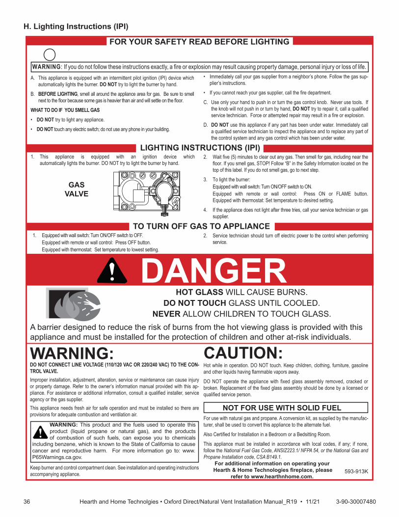
3636 3-90-30007480Hearth and Home Technolgies • Oxford Direct/Natural Vent Installation Manual_R19 • 11/21
FOR YOUR SAFETY READ BEFORE LIGHTING
TO TURN OFF GAS TO APPLIANCE
1. This appliance is equipped with an ignition device whichautomatically lights the burner. DO NOT try to light the burner by hand.
1. Equipped with wall switch: Turn ON/OFF switch to OFF. Equipped with remote or wall control: Press OFF button. Equipped with thermostat: Set temperature to lowest setting.
WARNING: If you do not follow these instructions exactly, a fi re or explosion may result causing property damage, personal injury or loss of life.
WARNING:
NOT FOR USE WITH SOLID FUEL
GASVALVE
For additional information on operating your Hearth & Home Technologies fi replace, please
refer to www.hearthnhome.com.
A. This appliance is equipped with an intermittent pilot ignition (IPI) device which automatically lights the burner. DO NOT try to light the burner by hand.
B. BEFORE LIGHTING, smell all around the appliance area for gas. Be sure to smell next to the fl oor because some gas is heavier than air and will settle on the fl oor.
WHAT TO DO IF YOU SMELL GAS• DO NOT try to light any appliance.
• DO NOT touch any electric switch; do not use any phone in your building.
DO NOT CONNECT LINE VOLTAGE (110/120 VAC OR 220/240 VAC) TO THE CON-TROL VALVE.Improper installation, adjustment, alteration, service or maintenance can cause injury or property damage. Refer to the owner’s information manual provided with this ap-pliance. For assistance or additional information, consult a qualifi ed installer, service agency or the gas supplier.This appliance needs fresh air for safe operation and must be installed so there are provisions for adequate combustion and ventilation air.
Hot while in operation. DO NOT touch. Keep children, clothing, furniture, gasoline and other liquids having fl ammable vapors away.
DO NOT operate the appliance with fi xed glass assembly removed, cracked or broken. Replacement of the fi xed glass assembly should be done by a licensed or qualifi ed service person.
• Immediately call your gas supplier from a neighbor’s phone. Follow the gas sup-plier’s instructions.
• If you cannot reach your gas supplier, call the fi re department.
C. Use only your hand to push in or turn the gas control knob. Never use tools. If the knob will not push in or turn by hand, DO NOT try to repair it, call a qualifi ed service technician. Force or attempted repair may result in a fi re or explosion.
D. DO NOT use this appliance if any part has been under water. Immediately call a qualifi ed service technician to inspect the appliance and to replace any part of the control system and any gas control which has been under water.
For use with natural gas and propane. A conversion kit, as supplied by the manufac-turer, shall be used to convert this appliance to the alternate fuel.
Also Certifi ed for Installation in a Bedroom or a Bedsitting Room.
,enon fi ;yna fi ,sedoc lacol htiw ecnadrocca ni dellatsni eb tsum ecnailppa sihTfollow the National Fuel Gas Code, ANSIZ223.1/ NFPA 54, or the National Gas and Propane Installation code, CSA B149.1.
LIGHTING INSTRUCTIONS (IPI)2. Wait fi ve (5) minutes to clear out any gas. Then smell for gas, including near the
fl oor. If you smell gas, STOP! Follow “B” in the Safety Information located on the top of this label. If you do not smell gas, go to next step.
3. To light the burner: Equipped with wall switch: Turn ON/OFF switch to ON. Equipped with remote or wall control: Press ON or FLAME button.
Equipped with thermostat: Set temperature to desired setting.
4. If the appliance does not light after three tries, call your service technician or gas supplier.
2. Service technician should turn off electric power to the control when performing service.
DANGERHOT GLASS WILL CAUSE BURNS.
DO NOT TOUCH GLASS UNTIL COOLED.NEVER ALLOW CHILDREN TO TOUCH GLASS.
CAUTION:A barrier designed to reduce the risk of burns from the hot viewing glass is provided with this appliance and must be installed for the protection of children and other at-risk individuals.
593-913K
WARNING: This product and the fuels used to operate this product (liquid propane or natural gas), and the products of combustion of such fuels, can expose you to chemicals
including benzene, which is known to the State of California to cause cancer and reproductive harm. For more information go to: www.P65Warnings.ca.gov.
Keep burner and control compartment clean. See installation and operating instructions accompanying appliance.
H. Lighting Instructions (IPI)

3737 3-90-30007480Hearth and Home Technolgies • Oxford Direct/Natural Vent Installation Manual_R19 • 11/21
I. Lighting TroubleshootingSIT NOVA 820 MILLIVOLT VALVENOTE: Before trouble shooting the gas control system, be sure external gas shut off is in the “On” position.
Symptom Possible Cause Corrective Action1. Spark ignitor will not light A. Defective or misaligned electrode at
pilot.Using a match, light pilot. If pilot lights, turn off pilot and push the red button again. If pilot will not light - check gap at electrode and pilot-should be 1/8” to have a strong spark.
B. Defective ignitor (Push Button) With the control knob in the pilot position, push the control knob all the way and hold. Check for spark at electrode and pilot. If no spark to pilot, and electrode wire is properly connected, replace the battery in the ignitor module and try again. Refer to Maintenance Section. If the problem still exists, replace the ignitor module box.
2. Pilot will not stay lit after carefully fol-lowing lighting instructions
A. Defective pilot generator (thermocou-ple), remote wall switch
Check pilot flame. Must impinge on thermo-couple/thermopile. NOTE: This pilot burner assembly utilizes both a thermocouple and a thermopile. The thermocouple operates the main valve operation (On and Off). Clean and or adjust pilot for maximum flame im-pingement on thermopile and thermocouple.
B. Defective automatic valve Turn valve knob to “Pilot”. Maintain flow to pilot; millivolt meter should read greater than 10mV. If the reading is okay and the pilot does not stay on, replace the gas valve. NOTE: An interrupter block (not supplied) must be used to conduct this test.
3. Pilot burning, no gas to main burner A. Wall switch or wires defective Check wall switch and wires for proper connections. Jumper wire across terminals at wall switch, if burner comes on, replace defective wall switch.. If okay, jumper wires across wall switch wires at valve, if burner comes on, wires are faulty or connections are bad.
B. Thermopile may not be generating sufficient millivoltage
1. Be sure wire connections form thermopile at gas valve terminals are tight and ther-mopile is fully inserted into pilot bracket.
2. One of the wall switch wires may be grounded. Remove wall switch wires form valve terminals if pilot now stays lit, trace wall switch wiring for ground. May be grounded to fireplace or gas supply.
3. Check thermopile with millivolt meter. Take reading at thermopile terminals of gas valve. Should read 250-300 milli-volts (minimum 150) while holding valve knob depressed in pilot position and wall switch “Off”. Replace faulty thermopile if reading is below specified minimum
C. Plugged burner orifice Check burner orifices for debris and remove.
D. Defective automatic valve operator Turn valve knob to “On”, place wall switch to “On” millivolt meter should read greater than 150mV. If the reading is okay and the burner does not come on, replace the gas valve.
4. Frequent pilot outage problem A. Pilot flame may be too low or blowing (high) causing the pilot safety to drop out
Clean and/or adjust pilot flame for maximum flame impingement on thermopile and ther-mocouple.
B. Possible blockage of the vent terminal Check the vent terminal for blockage (recy-cling the flue gases).
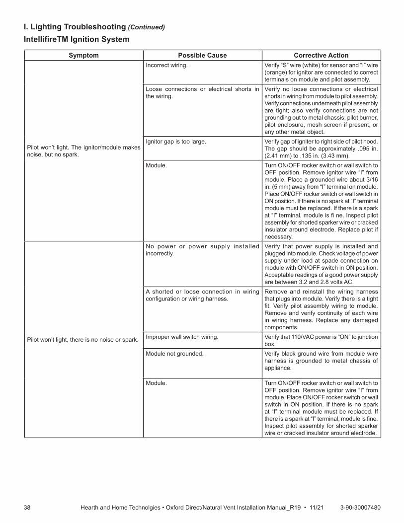
3838 3-90-30007480Hearth and Home Technolgies • Oxford Direct/Natural Vent Installation Manual_R19 • 11/21
I. Lighting Troubleshooting (Continued)
IntellifireTMIgnitionSystem
Symptom Possible Cause Corrective Action
Pilot won’t light. The ignitor/module makes noise, but no spark.
Incorrect wiring. Verify “S” wire (white) for sensor and “I” wire (orange) for ignitor are connected to correct terminals on module and pilot assembly.
Loose connections or electrical shorts in the wiring.
Verify no loose connections or electrical shorts in wiring from module to pilot assembly. Verify connections underneath pilot assembly are tight; also verify connections are not grounding out to metal chassis, pilot burner, pilot enclosure, mesh screen if present, or any other metal object.
Ignitor gap is too large. Verify gap of igniter to right side of pilot hood. The gap should be approximately .095 in. (2.41 mm) to .135 in. (3.43 mm).
Module. Turn ON/OFF rocker switch or wall switch to OFF position. Remove ignitor wire “I” from module. Place a grounded wire about 3/16 in. (5 mm) away from “I” terminal on module. Place ON/OFF rocker switch or wall switch in ON position. If there is no spark at “I” terminal module must be replaced. If there is a spark at “I” terminal, module is fi ne. Inspect pilot assembly for shorted sparker wire or cracked insulator around electrode. Replace pilot if necessary.
Pilot won’t light, there is no noise or spark.
No power or power supply installed incorrectly.
Verify that power supply is installed and plugged into module. Check voltage of power supply under load at spade connection on module with ON/OFF switch in ON position. Acceptable readings of a good power supply are between 3.2 and 2.8 volts AC.
A shorted or loose connection in wiring configuration or wiring harness.
Remove and reinstall the wiring harness that plugs into module. Verify there is a tight fit. Verify pilot assembly wiring to module. Remove and verify continuity of each wire in wiring harness. Replace any damaged components.
Improper wall switch wiring. Verify that 110/VAC power is “ON” to junction box.
Module not grounded. Verify black ground wire from module wire harness is grounded to metal chassis of appliance.
Module. Turn ON/OFF rocker switch or wall switch to OFF position. Remove ignitor wire “I” from module. Place ON/OFF rocker switch or wall switch in ON position. If there is no spark at “I” terminal module must be replaced. If there is a spark at “I” terminal, module is fine. Inspect pilot assembly for shorted sparker wire or cracked insulator around electrode.

3939 3-90-30007480Hearth and Home Technolgies • Oxford Direct/Natural Vent Installation Manual_R19 • 11/21
Symptom Possible Cause Corrective Action
Pilot sparks, but Pilot will not light.
Gas supply. Verify that incoming gas line ball valve is “open”. Verify that inlet pressure reading is within acceptable limits.
Ignitor gap is incorrect. Verify gap of igniter to right side of pilot hood. The gap should be approximately .095 in. (2.41 mm) to .135 in. (3.43 mm).
Module is not grounded. Verify module is securely grounded to metal chassis of appliance.
Module voltage output/Valve/Pilot solenoid ohms readings.
Verify battery voltage is at least 2.7 volts. Replace batteries if voltage is below 2.7.
Pilot lights but continues to spark, and main burner will not ignite. (If the pilot continues to spark after the pilot flame has been lit, flame rectification has not occurred.)
A shorted or loose connection in flame sensing rod.
Veri fy al l connect ions to wir ing diagram in manual. Verify connections underneath pilot assembly are tight. Verify connections are not grounding out to metal chassis, pilot burner, pilot enclosure or screen if present, or any other metal object.
Poor flame rectification or contaminated flame sensing rod.
With fixed glass assembly in place, verify that flame is engulfing flame sensing rod on left side of pilot hood. Flame sensing rod should glow shortly after ignition. Verify correct pilot orifice is installed and gas inlet is set to pressure specifications.
Module is not grounded. Verify module is securely grounded to metal chassis of appliance. Verify that wire harness is firmly connected to the module.
Damaged pilot assembly or contaminated flame sensing rod.
Verify that ceramic insulator around the flame sensing rod is not cracked, damaged, or loose. Verify connection from flame sensing rod to white sensor wire. Clean flame sensing rod with emery cloth to remove any contaminants that may have accumulated on flame sensing rod. Verify continuity with a multimeter with ohms set at lowest range. Replace pilot if any damage is detected.
Module. Turn ON/OFF rocker switch or wall switch to OFF position. Remove ignitor wire “I” from module. Place ON/OFF rocker switch or wall switch in ON position. If there is no spark at “I” terminal module must be replaced. If there is a spark at “I” terminal, module is fine.
IntellifireIgnitionSystem-(continued)

4040 3-90-30007480Hearth and Home Technolgies • Oxford Direct/Natural Vent Installation Manual_R19 • 11/21
J. Burner, Pilot & Control Compartment
Keep the control compartment and burner areas clean by vacuuming or brushing at least twice a year. Make sure the burner porting, pilot air opening and burner air opening are free of obstructions at all times.Pilot FlameThe flames from the pilot should be visually checked as soon as the heater is installed and periodically during normal operation. The pilot flame must always be present when the stove is in operation, Figure 6.4. The pilot flame has three distinct flames, one engulfing the sensor, one engulfing the thermopile, and the other reaching to the main burner.
WARNING!Turn off gas before servicing stove. It is recommended that a qualified service technician perform these check-ups at the beginning of each heating season
Figure 6.4 - Pilot Flame
CO105dPilot flame6/07 djt
BurnerInspect area around the injector. Remove any lint or foreign material with a brush or vacuum. Burner FlameThe flames from the burner should be visually checked as soon as the heater is installed and periodically during normal operation. In normal operation, at full rate, and after operating for about 15 to 30 minutes, the flame should be yellow. NOTE:Thetypeofinstallation,ventsystemconfiguration,andwindeffectsmaycausetheflamepatternstovary.
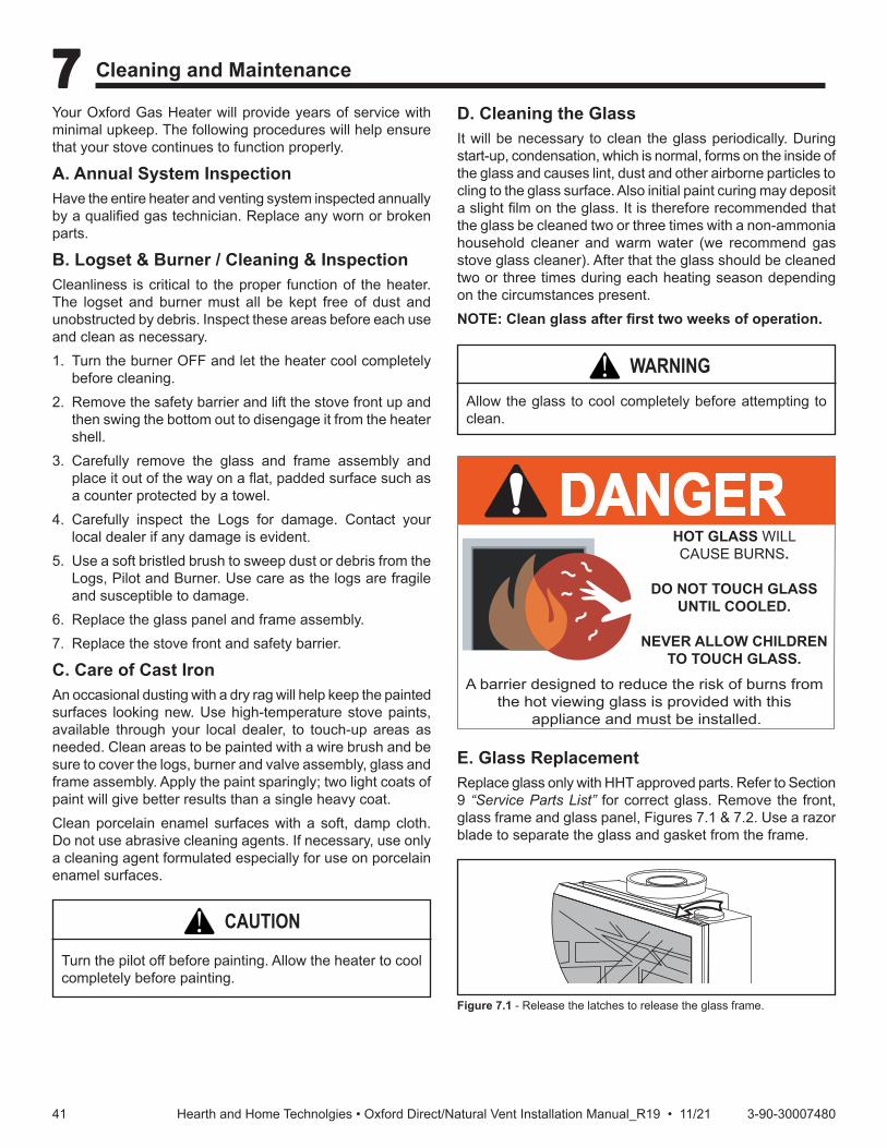
4141 3-90-30007480Hearth and Home Technolgies • Oxford Direct/Natural Vent Installation Manual_R19 • 11/21
Your Oxford Gas Heater will provide years of service with minimal upkeep. The following procedures will help ensure that your stove continues to function properly.
A. Annual System InspectionHave the entire heater and venting system inspected annually by a qualified gas technician. Replace any worn or broken parts.
B. Logset & Burner / Cleaning & InspectionCleanliness is critical to the proper function of the heater. The logset and burner must all be kept free of dust and unobstructed by debris. Inspect these areas before each use and clean as necessary.1. Turn the burner OFF and let the heater cool completely
before cleaning.2. Remove the safety barrier and lift the stove front up and
then swing the bottom out to disengage it from the heater shell.
3. Carefully remove the glass and frame assembly and place it out of the way on a flat, padded surface such as a counter protected by a towel.
4. Carefully inspect the Logs for damage. Contact your local dealer if any damage is evident.
5. Use a soft bristled brush to sweep dust or debris from the Logs, Pilot and Burner. Use care as the logs are fragile and susceptible to damage.
6. Replace the glass panel and frame assembly.7. Replace the stove front and safety barrier.
C. Care of Cast IronAn occasional dusting with a dry rag will help keep the painted surfaces looking new. Use high-temperature stove paints, available through your local dealer, to touch-up areas as needed. Clean areas to be painted with a wire brush and be sure to cover the logs, burner and valve assembly, glass and frame assembly. Apply the paint sparingly; two light coats of paint will give better results than a single heavy coat.Clean porcelain enamel surfaces with a soft, damp cloth. Do not use abrasive cleaning agents. If necessary, use only a cleaning agent formulated especially for use on porcelain enamel surfaces.
D. Cleaning the GlassIt will be necessary to clean the glass periodically. During start-up, condensation, which is normal, forms on the inside of the glass and causes lint, dust and other airborne particles to cling to the glass surface. Also initial paint curing may deposit a slight film on the glass. It is therefore recommended that the glass be cleaned two or three times with a non-ammonia household cleaner and warm water (we recommend gas stove glass cleaner). After that the glass should be cleaned two or three times during each heating season depending on the circumstances present.NOTE:Cleanglassafterfirsttwoweeksofoperation.
CAUTION!Turn the pilot off before painting. Allow the heater to cool completely before painting.
WARNING!Allow the glass to cool completely before attempting to clean.
7 7 Cleaning and Maintenance
E. Glass ReplacementReplace glass only with HHT approved parts. Refer to Section 9 “Service Parts List” for correct glass. Remove the front, glass frame and glass panel, Figures 7.1 & 7.2. Use a razor blade to separate the glass and gasket from the frame.
Figure 7.1 - Release the latches to release the glass frame.
ST208glass swivel latch12/99
DANGERHOT GLASS WILLCAUSE BURNS.
DO NOT TOUCH GLASSUNTIL COOLED.
NEVER ALLOW CHILDRENTO TOUCH GLASS.
A barrier designed to reduce the risk of burns from the hot viewing glass is provided with this
appliance and must be installed.

4242 3-90-30007480Hearth and Home Technolgies • Oxford Direct/Natural Vent Installation Manual_R19 • 11/21
F. Gasket ReplacementThe heater uses a ‘tadpole’ type gasket to seal between the glass panel and the frame. In time, this gasket can become brittle and compressed and should be replaced. New gasket is available from your dealer.Shut off the gas supply and allow the stove to cool. Wear safety goggles and a dust mask.1. Remove the Front, Glass Frame and Glass Panel.
(Figures 7.1 & 7.2) Remove the old gasket. Use a razor blade to separate the glass and gasket from the frame, and to clean the glass of any remaining cement or bits of gasket. Use a cold chisel if necessary.
2. Determine the correct length of gasket by laying it out around the edge of the glass. Allow an extra 1 - 2” (25-50 mm). Mark the spot to be cut. Use a utility knife.
3. Starting on a long edge, remove about 6” of the protective paper strip and apply the flat adhesive face of the gasket around the outside-facing edge of the panel. Continue around the panel, applying a bout 6” at a time and being careful to not stretch the material. Do not overlap the gasket ends, Figure 7.2.
4. Apply a thin bead of high temperature silicone rubber sealant along the inside corner of the glass frame, all around the perimeter. Place the flat gasketed side of the glass panel back into the steel frame. Pinch the rounded inside-facing gasket material to bulk it up.
5. Replace the glass frame and front panel as previously described.
ST179glass gasket detail11/99
Figure 7.2 - Wrap the gasket material around the outside edge of the glass.
G. Check the Gas Flame RegularlyTo ensure that the stove is operating properly, check the flames periodically to confirms they match Figure 7.3. The flames will be blue during the first 15-20 minutes of operation, and will gradually turn to yellow after that.Do not use your stove if the flame pattern differs from that shown. Contact your dealer or a qualified technician for help.
LG142StardanceInstall logs 212/11/00 djt
Red Glow
Figure 7.4 - Correct flame pattern.
H. Stove DisassemblyIf there is ever a need to remove the firebox assembly from the stove shell, support the firebox with solid stands about 6” (150 mm) tall under the left and right outer edges of the firebox base. Do not set the firebox assembly directly on the floor; this can damage the control valve and/or the gas lines from the valve to the firebox.Before removing the firebox from the shell, disconnect the on/off switch wires from the valve. If the assembly includes the optional fan, disconnect the fan rheostat. If the installation includes a wall thermostat, disconnect the thermostat leads from valve.Disconnection and reconnection to the gas line should only be done by a qualified gas service technician.Upon reinstallation, the vent system must be sealed to the firebox as shown in the installation section. Also be sure the logs are placed in the firebox correctly.
Figure 7.3 - IPI Flame Pattern
OXDV MODELS
OXDV-IPI
CO105dPilot flame6/07 djt

4343 3-90-30007480Hearth and Home Technolgies • Oxford Direct/Natural Vent Installation Manual_R19 • 11/21
I. Maintenance FrequencyVentingFrequency: SeasonallyBy: HomeownerTools needed: Protective gloves and safety glasses.• Inspect venting and termination cap for blockage or
obstruction such plants, bird nests, leaves, snow, debris, etc.
• Verify termination cap clearance to subsequent construction (building additions, decks, fences, or sheds).
• Inspect for corrosion or separation.• Verify weather stripping, sealing and flashing remains
intact.• Inspect draft shield to verify it is not damaged or missing.Maintenance Tasks-Service TechnicianThe following tasks must be performed by a qualified technician.Gasket Seal and Glass Assembly InspectionFrequency: AnnuallyBy: Service TechnicianTools needed: Protective gloves, drop cloth and a stablework surface.• Inspect gasket seal and its condition.• Inspect fixed glass assembly for scratches and nicks that
can lead to breakage when exposed to heat.• Confirm there is no damage to glass or glass frame.
Replace as necessary.• Verify that fixed glass assembly is properly retained and
attachment components are intact and not damaged. Replace as necessary.
LogsFrequency: AnnuallyBy: Service TechnicianTools needed: Protective gloves.• Inspect for damaged or missing logs. Replace as
necessary.• Verify correct log placement and no flame impingement
causing sooting. Correct as necessary.
Burner Ignition and OperationFrequency: AnnuallyBy: Service TechnicianTools needed: Protective gloves, vacuum cleaner, whisk broom, flashlight, voltmeter, indexed drill bit set, and a manometer.• Verify burner is properly secured and aligned with pilot or
igniter.• Clean off burner top.• Verify batteries have been removed from battery back-
up IPI systems to prevent premature battery failure or leaking.
• Check for smooth lighting and ignition carryover to all ports. Verify that there is no ignition delay.
• Inspect for lifting or other flame problems.• Verify air shutter setting is correct. See Section “4-F
Burner Information” for required air shutter setting. Verify air shutter is clear of dust and debris.
• Inspect orifice for soot, dirt and corrosion. Verify orifice size is correct. See Service Parts List for proper orifice sizing.
• Verify manifold and inlet pressures. Adjust regulator as required.
• Inspect pilot flame pattern and strength. See Figure 7.3 for proper pilot flame pattern. Clean or replace orifice spud as necessary.
• Inspect IPI flame sensing rod for soot, corrosion and deterioration. Polish with fine steel wool or replace as required.
• Verify IPI millivolt output. Replace as necessary.

4444 3-90-30007480Hearth and Home Technolgies • Oxford Direct/Natural Vent Installation Manual_R19 • 11/21
8 8 Wiring Diagrams
Millivolt Wiring DiagramsOFF ON
Thermostat(Optional)
Ther
mop
ile
Bla
ck
Black
MillivoltGas Valve
St124bon/off/switchwiring1/11/00 djt
TP/TH
TP
TH
On/OffSwitchWiring
Thermostat(Optional)
Ther
mop
ile
Bla
ck
Black
MillivoltGas Valve
St124cThermostatwiring1/11/00 djt
TP/TH
TP
TH
Optional Thermostat Wiring
Figure 8.1 - On/Off switch and optional thermostat circuit.
NOTE: IF ANY OF THE ORIGINAL WIRE, AS SUPPLIED WITH THE APPLIANCE, MUST BE REPLACED, IT MUST BE REPLACED WITH TYPE SF-2, 200° WIRE OR ITS EQUIVALENT.
Ther
moc
oupl
e
Safety LimitSwitch
Valve
ST665Safety Limit
Switch wiring5/29/01 djt
Figure 8.2 - Draft hood adapter wiring. Refer to Section 5 “Electrical Information” Figure 5.1.
FAN JUNCTION BOX
FANPOWERCORD
Strain Relief
Chassis Ground
BLK
GRN
GRN
WHT
ON / OFFRheostat
ChassisGround
RHEOSTAT / SNAPSTATBOX
Snapstat
BLKBLK
BLK
BLKBLK
WHT
ST153 rdv connections diag.10/99
MOTOR
SNAPST AT
ON/OFFRHEOST AT
WHT
WHT
BLKBLK
BLK
GRN
BLK
ST236FK26 wiring diagram12/99
Schematic Diagram
Figure 8.3 - Fan circuit.
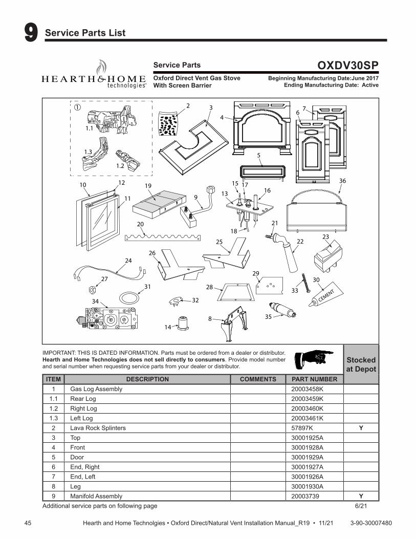
4545 3-90-30007480Hearth and Home Technolgies • Oxford Direct/Natural Vent Installation Manual_R19 • 11/21
9 9 Service Parts List
Service Parts OXDV30SPBeginning Manufacturing Date:June 2017
Ending Manufacturing Date: Active
IMPORTANT: THIS IS DATED INFORMATION. Parts must be ordered from a dealer or distributor. Hearth and Home Technologies does not sell directly to consumers. Provide model number and serial number when requesting service parts from your dealer or distributor.
Stocked at Depot
ITEM DESCRIPTION COMMENTS PART NUMBER1 Gas Log Assembly 20003458K
1.1 Rear Log 20003459K1.2 Right Log 20003460K1.3 Left Log 20003461K2 Lava Rock Splinters 57897K Y3 Top 30001925A4 Front 30001928A5 Door 30001929A6 End, Right 30001927A7 End, Left 30001926A8 Leg 30001930A9 Manifold Assembly 20003739 Y
Additional service parts on following page 6/21
Oxford Direct Vent Gas StoveWith Screen Barrier
1.1
1.2
1.3
2
10 12
11
20
24
25
29
CEMENT31
32
1 34
6 7
5
8
13
15 1716
18
14
2223
21
30
26
28
9
19
27
33
34
35
36

4646 3-90-30007480Hearth and Home Technolgies • Oxford Direct/Natural Vent Installation Manual_R19 • 11/21
Service Parts OXDV30SPBeginning Manufacturing Date:June 2017
Ending Manufacturing Date: Active
IMPORTANT: THIS IS DATED INFORMATION. Parts must be ordered from a dealer or distributor. Hearth and Home Technologies does not sell directly to consumers. Provide model number and serial number when requesting service parts from your dealer or distributor.
Stocked at Depot
ITEM DESCRIPTION COMMENTS PART NUMBER10 Glass 1601691 Y11 Glass Frame Assembly 30000127 Y12 Gasket, Glass, Medium Knit 1203702K
13 Pilot Assembly, 3 Way N/DV RN 0.199.706 SRV10002264 YN/DV RP 0.199.703 SRV10002265 Y
14Orifice Hood, Rear
#54 - LP 20000130 Y#44 - NG SRV30000334 Y
Orifice Hood, Front#69 - LP 30000513 Y#54 - NG 20000130 Y
15 Thermocouple 24” SRV24D0808 Y16 Thermocouple 18” RS SRV26D0566 Y17 Electrode Ignitor w/Cable SIT24 10001297 Y18 Tubing Pilot w/Fittings, 1/8x24” 26D0665 Y19 Burner Housing Assembly NG/LP 20002214K Y
Ceramic Burner Tile SRV57803 Y20 Grate, Burner 2000216721 Ashdoor Handle Assembly 500424122 Handle, Damper Maple Wood, Black 1600664 Y23 Switch ON/OFF 30000874 Y24 Wiring Harness 10002582 Y25 Right Log Bracket 2000216626 Left Log Bracket 2000216527 Nut, Hex Jam 3/8-16 TOPLK-Z Pkg of 10 1203290-1028 Gasket, Base Pan 20002282 Y29 Gasket, Base Pan Inner 20002566 Y30 Gasket Cement, 3oz Tube 1206122 Y31 Gasket, HE Door 1203687A Y32 Sensor 2450 CMG - 184-0032 10002013 Y33 Pan Head SL 1/4-20x3-Z Pkg of 10 1201310-1034 Valve, Nova SIT 230-0710 Y35 Ignitor Piezo w/Nut SIT 057958A Y
Bracket Piezo Ignitor 20010876K
Magnet, Control Door Use common super glue or silicone to attach 1408818
36 Safety Barrier 30007256 YTouch Up Paint Classic Black 3-42-19905Firebox 30000057Finish Bag SRV693831

4747 3-90-30007480Hearth and Home Technolgies • Oxford Direct/Natural Vent Installation Manual_R19 • 11/21
Service Parts OXDV30SPBeginning Manufacturing Date:June 2017
Ending Manufacturing Date: Active
IMPORTANT: THIS IS DATED INFORMATION. Parts must be ordered from a dealer or distributor. Hearth and Home Technologies does not sell directly to consumers. Provide model number and serial number when requesting service parts from your dealer or distributor.
Stocked at Depot
ITEM DESCRIPTION COMMENTS PART NUMBERStarter Collar Assembly 20307738K
Optional AccessoriesFan Kit BK-VCPush Button, On/Off RCBPush Button, On/Off Timer RCMTPush Button, On/Off Thermostat RCSTTouch Screen, On/Off Timer No longer available TSMTTouch Screen, On/Off Thermostat, On/Off Timer TSSTWired Wall Switch with 15 Ft. Wire and Wall Plate MVWS
Conversion KitsConversion Kit, NG to LP LPK-OXDV30-SP YConversion Kit, LP to NG 30005155 Y

4848 3-90-30007480Hearth and Home Technolgies • Oxford Direct/Natural Vent Installation Manual_R19 • 11/21
Service Parts OXDV30-IPIBeginning Manufacturing Date:Feb 2019
Ending Manufacturing Date: ActiveOxford Direct Vent Gas StoveWith Screen Barrier and IPI Controls
Part number list on following page.06/21
1.1
1.2
1.3
2
10 12
11
21
2526
30
CEMENT31
1 34
6 7
5
8
14
2324
22
32
27
29
9
20
28
33
13
15
16171819
34

4949 3-90-30007480Hearth and Home Technolgies • Oxford Direct/Natural Vent Installation Manual_R19 • 11/21
Service Parts OXDV30-IPIBeginning Manufacturing Date:Feb 2019
Ending Manufacturing Date: Active
IMPORTANT: THIS IS DATED INFORMATION. Parts must be ordered from a dealer or distributor. Hearth and Home Technologies does not sell directly to consumers. Provide model number and serial number when requesting service parts from your dealer or distributor.
Stocked at Depot
ITEM DESCRIPTION COMMENTS PART NUMBER1 Gas Log Assembly 20003458K
1.1 Rear Log 20003459K1.2 Right Log 20003460K1.3 Left Log 20003461K2 Lava Rock Splinters 57897K Y3 Top 30001925A4 Front 30001928A5 Door 30001929A6 End, Right 30001927A7 End, Left 30001926A8 Leg 30001930A9 Manifold Assembly 20003739 Y
10 Glass 1601691 Y11 Glass Frame Assembly 30000127 Y12 Gasket, Glass, Medium Knit 1203702K
13 Pilot Assembly NG SRV2090-012 Y
Propane 2090-013 Y
14Orifice Hood, Rear
#54 - LP 20000130 Y#44 - NG SRV30000334 Y
Orifice Hood, Front#69 - LP 30000513 Y#54 - NG 20000130 Y
15 Valve NG 750-500 Y
Propane 750-501 Y16 Transformer, 3V SRV593-593 Y17 Battery Pack SRV593-594 Y18 Wire Assembly SRV593-590 Y19 Module 593-592 Y20 Burner Housing Assembly NG/Propane 20002214K Y
Ceramic Burner Tile SRV57803 Y21 Grate, Burner 2000216722 Ashdoor Handle Assembly 500424123 Handle, Damper Maple Wood, Black 1600664 Y24 Switch ON/OFF 30000874 Y25 Wiring Harness SRV30007499 Y26 Right Log Bracket 20002166
Additional service parts on following page

5050 3-90-30007480Hearth and Home Technolgies • Oxford Direct/Natural Vent Installation Manual_R19 • 11/21
Service Parts OXDV30-IPIBeginning Manufacturing Date:Feb 2019
Ending Manufacturing Date: Active
IMPORTANT: THIS IS DATED INFORMATION. Parts must be ordered from a dealer or distributor. Hearth and Home Technologies does not sell directly to consumers. Provide model number and serial number when requesting service parts from your dealer or distributor.
Stocked at Depot
ITEM DESCRIPTION COMMENTS PART NUMBER27 Left Log Bracket 2000216528 Nut, Hex Jam 3/8-16 TOPLK-Z Pkg of 10 1203290-1029 Gasket, Base Pan 20002282 Y30 Gasket, Base Pan Inner 20002566 Y31 Gasket, HE Door 1203687A Y32 Gasket Cement, 3oz Tube 1206122 Y33 Pan Head SL 1/4-20x3-Z Pkg of 10 1201310-10
Magnet, Control DoorUse common super glue or silicone to
attach1408818
34 Safety Barrier 30007256 YTouch Up Paint Classic Black 3-42-19905Firebox 30000057Finish Bag SRV30007481
Conversion Kits
Conversion KitNG to Propane LPK-OXDV30-IPI YPropane to NG SRV30007483 Y
Pilot OrificeNG SRV593-528 YPropane SRV593-527 Y
RegulatorNG NGK-DXV-50 YPropane SRVLPK-DXV Y

5151 3-90-30007480Hearth and Home Technolgies • Oxford Direct/Natural Vent Installation Manual_R19 • 11/21
10 10 Optional Accessories
Fan KitThe fan helps distribute heated air from within the firebox out into the room. The fan is controlled by a snapstat that turns power on and off as the firebox temperature rises above and falls below a preset temperature. A rheostat provides for variable fan speeds.Specifications115 Volt / 60Hz / .75 AmpsMaintenanceThe fan itself does not require regular maintenance, however, periodic cleaning of the fan and the surrounding area is required.InstallationRefer to the "Install the Optional Fan" section of this manual.
Remote ControlsThe remote control allows you to turn the heater on or off from anywhere in the room.
Model Functions ControlledRCB Push Button, ON/OFF
RCMT Push Button, ON/OFF, TimerRCST Push Button, ON/OFF, ThermostatTSMT Touch Screen, ON/OFF, TimerTSST Touch Screen, Thermostat, ON/OFF, Timer
MVWS Wired wall switch with 15 ft. wire and wall plate.
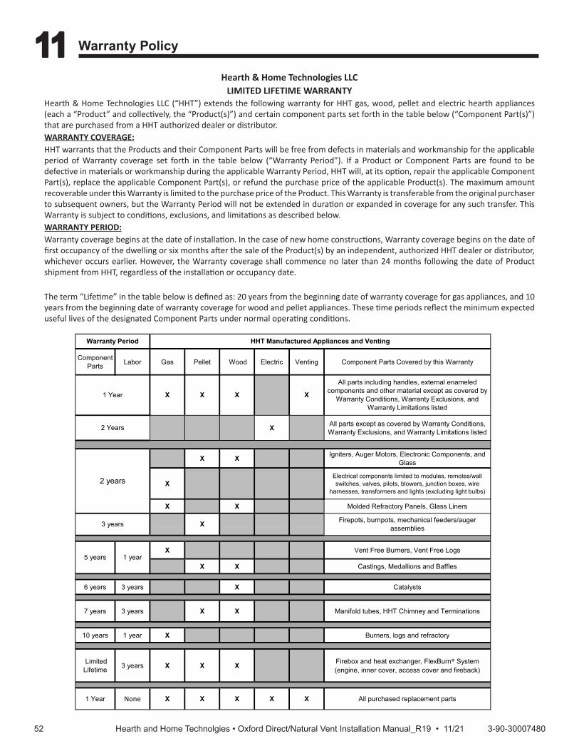
5252 3-90-30007480Hearth and Home Technolgies • Oxford Direct/Natural Vent Installation Manual_R19 • 11/21
Hearth & Home Technologies LLC LIMITED LIFETIME WARRANTY
Hearth & Home Technologies LLC (“HHT”) extends the following warranty for HHT gas, wood, pellet and electric hearth appliances (each a “Product” and collectively, the “Product(s)”) and certain component parts set forth in the table below (“Component Part(s)”) that are purchased from a HHT authorized dealer or distributor.WARRANTY COVERAGE:HHT warrants that the Products and their Component Parts will be free from defects in materials and workmanship for the applicable period of Warranty coverage set forth in the table below (“Warranty Period”). If a Product or Component Parts are found to be defective in materials or workmanship during the applicable Warranty Period, HHT will, at its option, repair the applicable Component Part(s), replace the applicable Component Part(s), or refund the purchase price of the applicable Product(s). The maximum amount recoverable under this Warranty is limited to the purchase price of the Product. This Warranty is transferable from the original purchaser to subsequent owners, but the Warranty Period will not be extended in duration or expanded in coverage for any such transfer. This Warranty is subject to conditions, exclusions, and limitations as described below. WARRANTY PERIOD:Warranty coverage begins at the date of installation. In the case of new home constructions, Warranty coverage begins on the date of first occupancy of the dwelling or six months after the sale of the Product(s) by an independent, authorized HHT dealer or distributor, whichever occurs earlier. However, the Warranty coverage shall commence no later than 24 months following the date of Product shipment from HHT, regardless of the installation or occupancy date.
The term “Lifetime” in the table below is defined as: 20 years from the beginning date of warranty coverage for gas appliances, and 10 years from the beginning date of warranty coverage for wood and pellet appliances. These time periods reflect the minimum expected useful lives of the designated Component Parts under normal operating conditions.
Page 1 of 24021-645L 10/20
Component Parts Labor Gas Pellet Wood Electric Venting Component Parts Covered by this Warranty
X All parts except as covered by Warranty Conditions, Warranty Exclusions, and Warranty Limitations listed
X X Igniters, Auger Motors, Electronic Components, and Glass
XElectrical components limited to modules, remotes/wall switches, valves, pilots, blowers, junction boxes, wire
harnesses, transformers and lights (excluding light bulbs)
X X Molded Refractory Panels, Glass Liners
X Vent Free Burners, Vent Free Logs
X X Castings, Medallions and Baffles
6 years 3 years X Catalysts
7 years 3 years X X Manifold tubes, HHT Chimney and Terminations
10 years 1 year X Burners, logs and refractory
Limited Lifetime 3 years X X X Firebox and heat exchanger, FlexBurn® System
(engine, inner cover, access cover and fireback)
1 Year None X X X X X All purchased replacement parts
Warranty Period HHT Manufactured Appliances and Venting
All parts including handles, external enameled components and other material except as covered by
Warranty Conditions, Warranty Exclusions, and Warranty Limitations listed
2 years
X1 Year X X X
2 Years
5 years 1 year
Firepots, burnpots, mechanical feeders/auger assemblies3 years X
11 11 Warranty Policy

5353 3-90-30007480Hearth and Home Technolgies • Oxford Direct/Natural Vent Installation Manual_R19 • 11/21
WARRANTY CONDITIONS:• Because HHT cannot control the quality of any Products sold by unauthorized sellers, this Warranty only covers Products that are
purchased through an HHT authorized dealer or distributor unless otherwise prohibited by law; a list of HHT authorized dealers is available on the HHT branded websites.
• This Warranty is only valid while the applicable Product remains at the site of original installation. • This Warranty is only valid in the country in which the HHT authorized dealer or distributor that sold the applicable Product is
authorized to sell applicable Product. • Contact your installing distributor or dealer for Warranty service. If the installing dealer or distributor is unable to provide
necessary parts, contact the nearest HHT authorized dealer or supplier. Additional service fees may apply if you are seeking Warranty service from a dealer other than the dealer from whom you originally purchased the applicable Product.
• No HHT consumer should bear cost of warranty service or costs incurred while servicing warranty claims (i.e., travel, gas, or mileage) when the service is performed within the terms of this Warranty. Check with your dealer or distributor in advance for any costs to you when arranging a warranty call. Travel and shipping charges for parts are not covered by this Warranty.
WARRANTY EXCLUSIONS:This Warranty does not cover the following:• Changes in surface finishes as a result of normal use. As a heating appliance, some changes in color of interior and exterior surface
finishes may occur. This is not a flaw and is not covered under the Warranty. • Damage to printed, plated, or enameled surfaces caused by fingerprints, accidents, misuse, scratches, melted items or other
external sources and residues left on the plated surfaces from the use of abrasive cleaners or polishes. • Repair or replacement of parts that are subject to normal wear and tear during the Warranty Period are not covered. These parts
include: paint, wood and pellet gaskets, firebricks, grates, flame guides, batteries and the discoloration of glass. • Minor expansion, contraction, or movement of certain parts causing noise. These conditions are normal and complaints related to
this noise are not covered by this Warranty.• Damages resulting from: (1) failure to install, operate, or maintain the applicable Product in accordance with the installation
instructions, operating instructions, and listing agent identification label furnished with the applicable Product; (2) failure to install the applicable Product in accordance with local building codes; (3) shipping or improper handling; (4) improper operation, abuse, misuse, continued operation with damaged, corroded or failed components, accident, or improperly/incorrectly performed repairs; (5) environmental conditions, inadequate ventilation, negative pressure, or drafting caused by tightly sealed constructions, insufficient make-up air supply, or handling devices such as exhaust fans or forced air furnaces or other such causes; (6) use of fuels other than those specified in the operation instructions; (7) installation or use of components not supplied with the applicable Product or any other components not expressly authorized and approved by HHT; (8) modification of the appliance not expressly authorized and approved by HHT in writing; and/or (9) interruptions or fluctuations of electrical power supply to the applicable Product.
• Non-HHT venting components, hearth connections or other accessories used in conjunction with the applicable Product. • Any part of a pre-existing fireplace system in which an insert or a decorative gas applicable Product is installed. • HHT’s obligation under this Warranty does not extend to the Product’s capability to heat the desired space. Information is provided
to assist the consumer and the dealer in selecting the proper Product for the application. Consideration must be given to the Product location and configuration, environmental conditions, insulation and air tightness of the structure.
This warranty is void if:• The applicable Product has been over-fired, operated in atmospheres contaminated by chlorine, fluorine, or other damaging
chemicals. Over-firing can be identified by, but not limited to, warped plates or tubes, deformation/warping of interior cast iron structure or components, rust colored cast iron, bubbling, cracking and discoloration of steel or enamel finishes.
• The applicable Product is subjected to prolonged periods of dampness or condensation. • There is any damage to the applicable Product due to water or weather damage which is the result of, but not limited to, improper
chimney or venting installation.
LIMITATIONS OF REMEDIES AND LIABILITY:• EXCEPT TO THE EXTENT PROVIDED BY LAW, HHT MAKES NO EXPRESS WARRANTIES OTHER THAN THE WARRANTY SPECIFIED
HEREIN. The owner’s exclusive remedy and HHT’s sole obligation under this Warranty or in contract, tort or otherwise, shall be limited to replacement of the Component Part(s), repair of the Component Part(s), or refund of the original purchase price of the applicable Product(s), as specified above; provided, however, that (i) if HHT is unable to provide replacement of the Component Part(s) and repair of the Component Part(s) is not commercially practicable or cannot be timely made, or (ii) the customer is willing to accept a refund of the purchase price of the applicable Product(s), HHT may discharge all such obligations by refunding the purchase price of the applicable Product. In no event will HHT be liable for any incidental or consequential damages caused by defects in the applicable Product. Some States do not allow the exclusion or limitation of incidental or consequential damages, so the above limitation or exclusion may not apply to you. This Warranty gives you specific legal rights and you may also have other rights which vary from State to State. THE DURATION OF ANY IMPLIED WARRANTY IS LIMITED TO DURATION OF THE EXPRESSED WARRANTY SPECIFIED ABOVE FOR THE APPLICABLE PRODUCT. Some States do not allow limitations on how long an implied warranty lasts, so the above limitation may not apply to you.
Page 2 of 24021-645L 10/20

5454 3-90-30007480Hearth and Home Technolgies • Oxford Direct/Natural Vent Installation Manual_R19 • 11/21
Based on CSA P.4.1-09
Recherchez dans la brochureles caractéristique de rendement
énergétique de foyer au gazÉnerguide
Selon CSA P.4.1-09
Based on CSA P.4.1-2015
EFFICIENCY RATINGS
MODEL
ENERGUIDE RATINGS STOVE EFFICIENCY
PERCENTAGED.O.E.
(AFUE PERCENTAGE)OXDV30SP Series 62.7 68.4OXDV30IPI Series 58.4 68.4
352 Mountain House Road • Halifax, PA 17032www.vermontcastings.com