system enhancements rev 04.3r4 - no markups-complete
DESCRIPTION
california chp radio system enchancements proposedTRANSCRIPT

CALIFORNIA HIGHWAY PATROL ENHANCED RADIO SYSTEM
(CHPERS)
Enhancement Design Document Revision 4.3r4
Prepared by
Office of the State Chief Information Officer Public Safety Communications Division
Office of Public Safety Communications Services
June xx, 2009

Prepared by OCIO, Public Safety Communications Division, Office of Public Safety Communications Services System Enhancements Rev 04.3r4.doc Last Save Date: 6/1/2009 3:29 PM Page 2 of 86
This page left intentionally blank.

Prepared by OCIO, Public Safety Communications Division, Office of Public Safety Communications Services System Enhancements Rev 04.3r4.doc Last Save Date: 6/1/2009 3:29 PM Page 3 of 86
CALIFORNIA HIGHWAY PATROL ENHANCED RADIO SYSTEM
Enhancement Design Document
Table of Contents
DOCUMENT REVISION HISTORY ..............................................................................................7
INTRODUCTION ..........................................................................................................................9
EXISTING RADIO SYSTEM.......................................................................................................11
OVERVIEW.................................................................................................................................11
1. General.................................................................................................................... 11
2. Conventional Radio System.................................................................................. 11
3. Simulcast Radio System ....................................................................................... 12
4. Standalone.............................................................................................................. 12
5. Base Stations ......................................................................................................... 13
6. Control of Base Stations ....................................................................................... 14
7. Communications Centers...................................................................................... 16
8. Lowband System.................................................................................................... 17
9. UHF System............................................................................................................ 19
10. Mobile Equipment .................................................................................................. 20
11. Radio Equipment at Other Facilities .................................................................... 21
12. Public Safety Microwave System ......................................................................... 22
CALIFORNIA HIGHWAY PATROL............................................................................................25
ENHANCED RADIO SYSTEM ...................................................................................................25
13. Simulcast Support in Existing Locations ............................................................ 25
14. Frequencies ............................................................................................................ 29 14.1. BLU Frequency Separation .........................................................................29 14.2. Primary Frequency ......................................................................................31 14.3. UHF Frequency ...........................................................................................32

Prepared by OCIO, Public Safety Communications Division, Office of Public Safety Communications Services System Enhancements Rev 04.3r4.doc Last Save Date: 6/1/2009 3:29 PM Page 4 of 86
14.4. 700 MHz Frequency ....................................................................................32 14.5. Car-to-Car Frequency..................................................................................32 14.6. Frequency Splits ..........................................................................................32
15. Use of Vote and Steer ............................................................................................ 33
16. Add Inbound Repeating to Critical Conventional Vote and Steer Areas .......... 33
17. CPVE for Interoperability and Network / Radio Integration................................ 34
18. 700 / 800 MHz Extended Range for Portable Communications ......................... 35
19. Replacement of CHP’s Radio Infrastructure ....................................................... 37 19.1. Facility Enhancements.................................................................................37 19.2. Remote Sites ...............................................................................................38 19.3. Communications Centers ............................................................................39 19.4. Area and Division Offices ............................................................................40 19.5. Inspection Facilities .....................................................................................40 19.6. Scale and Air Operations Facilities..............................................................41 19.7. Operational Cutover.....................................................................................42
20. Meeting FCC Requirements for Narrow Banding................................................ 43
21. Acquisition of Additional Radio Spectrum (Area, Division, Statewide) ............ 44
22. Dead Spot Mitigation ............................................................................................. 46
23. Integration of CHP Infrastructure With the State Digital Microwave System ...46
24. Communications Center Dispatch Console Upgrade......................................... 48
25. Radio Communications Interoperability Project (RCIP) ..................................... 49
26. Future Wide Area Network (WAN) Connectivity.................................................. 53
Appendix A ................................................................................................................................54 Figure A1. CHP Vote Steer Diagram................................................................................54 Figure A2. Typical Base Station Sketch ...........................................................................55 Figure A3. Console MEP Example ...................................................................................56 Figure A4. CHP Lowband Radio System Diagram...........................................................57 Figure A5. CHP Lowband Frequencies – Open List.........................................................58 Figure A6. CHP Lowband Radio System Map .................................................................59 Figure A7. CHP Areas With Primary Lowband VHF Channel Map ..................................60 Figure A8. CHP UHF Mobile Radio System Map .............................................................61 Figure A9. Public Safety Microwave System Map............................................................62
Appendix B ................................................................................................................................63 List B1. CHP Area Offices ................................................................................................63 List B2. CHP Communications Centers............................................................................63
Prepared by OCIO, Public Safety Communications Division, Office of Public Safety Communications Services System Enhancements Rev 04.3r4.doc Last Save Date: 6/1/2009 3:29 PM Page 5 of 86
List B3. CHP Inspection Facilities.....................................................................................64 List B4. CHP Public Scales, Resident Posts and Other Facilities ....................................64 List B5. Sites Requiring Facility Upgrades Via the Capital Outlay Process......................65
Appendix C ................................................................................................................................66 Figure C1. Example of Reuse of a Specific 700 MHz Frequency Throughout the State..66 Figure C2. Base Station Channels – 700 MHz Public Safety Band .................................67 Figure C3. Mobile Channels – 700 MHz Public Safety Band ...........................................68 Figure C4. Frequency Overview of Lowband VHF Frequencies Analyzed ......................69 Figure C5. Factors Included in Lowband VHF Frequency Analysis Includes Multiple
Frequency Searches of Existing FCC Licensed Users by Frequency ............70 Figure C6 (Sheet 1). Frequency Analysis Results of Potential Lowband VHF Frequency
Use for Specific Geographic Regions.............................................................71 Figure C6 (Sheet 2). Frequency Analysis Results of Potential Lowband VHF Frequency
Use for Specific Geographic Regions.............................................................72 Figure C7 (Sheet 1). CHPERS Lowband Frequency Plan (Phase 1)...............................73 Figure C7 (Sheet 2). CHPERS Lowband Frequency Plan (Phase 2)...............................74 Figure C7 (Sheet 3). CHPERS Lowband Frequency Plan (Phase 3)...............................75
Exhibits ......................................................................................................................................76 Exhibit 1. Simple Example of PSCD Work Package ........................................................76

Prepared by OCIO, Public Safety Communications Division, Office of Public Safety Communications Services System Enhancements Rev 04.3r4.doc Last Save Date: 6/1/2009 3:29 PM Page 6 of 86
This page left intentionally blank.

Prepared by OCIO, Public Safety Communications Division, Office of Public Safety Communications Services System Enhancements Rev 04.3r4.doc Last Save Date: 6/1/2009 3:29 PM Page 7 of 86
DOCUMENT REVISION HISTORY
DATE REVISION REASON MAJOR CHANGES MADE
7/23/2008 4.3 Original Baseline.
5/xx/2009 5.0 Quarterly Review
Multiple quarterly reviews incorporated. Added revision table. Clarified GGCC and LACC simulcast equipment will be purchased, but not installed, under CHPERS. Updated Appendix B, List B5.

Prepared by OCIO, Public Safety Communications Division, Office of Public Safety Communications Services System Enhancements Rev 04.3r4.doc Last Save Date: 6/1/2009 3:29 PM Page 8 of 86
This page left intentionally blank.

Prepared by OCIO, Public Safety Communications Division, Office of Public Safety Communications Services System Enhancements Rev 04.3r4.doc Last Save Date: 6/1/2009 3:29 PM Page 9 of 86
INTRODUCTION
The California Highway Patrol (CHP) has initiated the CHP Enhanced Radio System (CHPERS)
project. This enhancement project will provide an effective and efficient radio communications
system that supports CHP’s primary mission, improves internal and external services, and
enables radio interoperability with allied agencies during joint tactical operations and emergency
incidents.
The CHP Enhanced Radio System will:
• Acquire a Consolidated Patrol Vehicle Environment (CPVE) and associated new
mobile radios.
• Replace an aging custom-designed infrastructure with new industry standard
equipment.
• Allow officers the ability to communicate at a greater distance when away from their
enforcement vehicles.
• Allow communications centers to operate their primary and secondary frequencies
independently and simultaneous from each other.
• Be capable of automatically broadcasting inbound mobile transmissions over a wide
area so that most mobile units will have the ability to monitor mobile transmissions.
• Include additional radio channels for tactical and emergency operations.
• Enable radio interoperability with other public safety agencies without impacting day-
to-day patrol operations.
• Allow all communications centers to have multiple alternate dispatch control points for
control of the fixed radio system.
• Provide radio communications at inspection and scale facilities.
This document will provide a general overview of the existing CHP radio system and will discuss
the various aspects of the CHPERS project. More detailed information regarding the existing
CHP radio system can be obtained from the Office of the State Chief Information Officer
(OCIO), Public Safety Communications Division (PSCD) (formerly the Department of General
Services, Telecommunications Division). It is assumed that the reader has a basic under-

Prepared by OCIO, Public Safety Communications Division, Office of Public Safety Communications Services System Enhancements Rev 04.3r4.doc Last Save Date: 6/1/2009 3:29 PM Page 10 of 86
standing of the existing CHP radio system and the State’s Capital Outlay Budget Change
Proposal process.

Prepared by OCIO, Public Safety Communications Division, Office of Public Safety Communications Services System Enhancements Rev 04.3r4.doc Last Save Date: 6/1/2009 3:29 PM Page 11 of 86
CALIFORNIA HIGHWAY PATROL EXISTING RADIO SYSTEM
OVERVIEW
This section is a general overview of the existing California Highway Patrol (CHP) mobile radio
system. A brief description of the various types of radio systems used by the CHP is presented;
as well as, the types of radio base stations used and how they are controlled. Additionally, brief
descriptions of CHP’s communications centers, mobile and fixed location radio equipment, and
the State microwave system are presented. It is assumed that the reader has a basic familiarity
with the existing CHP radio system.
1. General
1.1. The CHP uses two major radio systems: a Very High Frequency (VHF) lowband
system and an Ultra High Frequency (UHF) system. The lowband system is used
by CHP as its main radio communications system with its regular patrol officers.
The UHF system is used by a smaller number of CHP Protective Services Division
officers for Dignitary Protection and other previous State Police responsibilities.
The radio systems are configured as either conventional (vote steer), simulcast or
standalone.
1.2. The equipment utilized in the CHP radio system is installed via the Public Safety
Communications Division’s (PSCD) COM 207 process. This process involves
PSCD engineering and field maintenance staff. The document(s) generated via
the COM 207 process details the scope of work being performed, required
associated parts, required schematics and detailed engineering work instructions
for the field maintenance staff. Exhibit 1 is an example of a simple COM 207 work
package for Horse Mountain which involved working at a remote site location that
is not a CHP managed vault. The COM 207 process permits interagency
cooperation when radio equipment is installed at sites not under the jurisdiction of
CHP. The COM 207 process also generates and/or updates any required site
documentation.
2. Conventional Radio System
2.1. Except for the Los Angeles Communications Center (LACC), Golden Gate
Communications Center (GGCC), Inland Communications Center (CC) and Border

Prepared by OCIO, Public Safety Communications Division, Office of Public Safety Communications Services System Enhancements Rev 04.3r4.doc Last Save Date: 6/1/2009 3:29 PM Page 12 of 86
CC which operate simulcast radio systems, the remaining CHP communications
centers operate conventional (vote steer) radio systems.
2.2. The CHP lowband conventional radio system is a vote steer system. The vote
steer radio system consists of multiple strategically located transmitters and
receivers. Receive audio from multiple sites is analyzed and the best receive
audio (voted audio) is presented to the dispatcher. The vote steer radio system
then automatically selects (“steers”) the transmitter associated with the voted audio
to reply to the mobile. Typically only one transmitter is selected at any given time.
The vote steer radio system is set up to vote with each new reception. The system
is also designed to ensure the voter only analyzes valid transmissions from
mobiles and not idle channel noise. Reference Appendix A, Figure A1, CHP Vote
Steer Diagram.
3. Simulcast Radio System
3.1. In addition to the conventional (vote steer) radio system, CHP also utilizes the
technique of simulcast (simultaneous broadcast) transmissions. In a conventional
mode, a single transmitter is keyed at any given time. In a simulcast mode, all
transmitters on the same frequency are keyed at the same time. Simulcast
operation also requires that the transmitters be aligned to one another.
3.2. The receive portion of a simulcast system is the same as the receive portion of a
vote steer system. Receive audio from multiple sites is compared (voted) and the
best receive audio (voted audio) is routed to the dispatcher. In the Inland CC,
Border CC and GGCC simulcast systems, the voted audio is also rebroadcasted
(repeated) over the air simultaneously via all transmitters on the same frequency.
When a dispatcher replies to a mobile, the dispatcher’s traffic is also broadcast out
on all associated transmitters simultaneously at the same time.
3.3. The following CHP communications centers operate in the simulcast mode: LACC,
Inland CC (San Bernardino), Border CC (San Diego) and GGCC.
4. Standalone
CHP also utilizes radios which operate in a standalone mode. Radios configured as
standalone consist of a console controlled base station which does not operate in
conventional (vote steer) or simulcast systems. These base stations typically appear as
secondary (auxiliary) stations on the console position. Oftentimes, the radios are part of

Prepared by OCIO, Public Safety Communications Division, Office of Public Safety Communications Services System Enhancements Rev 04.3r4.doc Last Save Date: 6/1/2009 3:29 PM Page 13 of 86
other state and local government radio systems. Examples of other government entities
are CLEMARS, CLERS, local sheriff offices and local police departments.
5. Base Stations
5.1. General Overview.
In general terms, a base station is any piece of fixed radio equipment that allows
radio frequency (RF) communications between end users. In the CHP Lowband
Radio System, there are two typical base station configurations: local and remote.
Other configurations are used depending on operational requirements. Reference
Appendix A, Figure A2, Typical Base Station Sketch.
5.2. Local Base Stations.
Local base stations are generally used at area offices. A local base station is
comprised of a transceiver (a single transmitter and receiver unit), two auxiliary
receivers, a transmit/receive (T/R) relay, filtering equipment (intermodulation panel,
etc.), and an antenna system. A local base station is connected to the area office’s
desktop console and not to a communications center’s dispatch console. The local
base station is used by an area office to communicate car-to-car (transmit and
receive using the “C” channel) on the office’s primary and Blue (BLU) frequencies
and to listen to the primary “S” channel.
5.3. Remote Base Stations.
Remote base stations are generally located at remote sites. A remote base station
is comprised of a transceiver (a single transmitter and receiver unit), one auxiliary
receiver, a T/R relay, filtering equipment (intermodulation panel, etc.), batteries and
charger, and an antenna system. Remote base stations normally require more
extensive filtering equipment and cavities than local base stations due to increased
frequency interference problems caused by multiple users at remote sites. A
remote base station is connected to a communications center’s dispatch console.
Remote base stations are used by dispatch to communicate to vehicles on the
primary and BLU frequencies. The “C” channel is used to transmit to the vehicles
and the “S” channel is used to listen to vehicles.
5.4. Remote Sites Versus Local Sites.
5.4.1. Base stations are located at radio sites. The term “remote site” is
generally used for radio sites that are located at remote locations. Most
of the time remote sites are located on mountain tops. Base stations at

Prepared by OCIO, Public Safety Communications Division, Office of Public Safety Communications Services System Enhancements Rev 04.3r4.doc Last Save Date: 6/1/2009 3:29 PM Page 14 of 86
remote sites are controlled by dispatchers via microwave circuits, RF
control links (usually 70 MHz, 150 MHz or 450 MHz), or leased telephone
lines.
5.4.2. The term “local site” is generally used for radio sites that are located in
cities. Most local sites are communications centers or area offices. At
local sites, since the radio vaults either share the same building as the
communications center or are located right next to the communications
center, the radios at local sites are generally controlled via house cables.
5.5. Continuous Tone Coded Squelch System (CTCSS).
A squelch system that uses a specific sub-audio tone (usually 50-200 Hz) in
conjunction with an RF carrier. This type of squelch system allows two or more
radio systems to share the same radio channel without interference to one another.
CTCSS is sometimes referred to as Private Line (PL) and Channel Guard (CG).
5.6. Auxiliary Receiver.
A standalone receiver unit that is not physically part of a transmitter.
6. Control of Base Stations
6.1. General Overview.
In the CHP Lowband Radio System, each base station is controlled by a console.
Each base station is connected to that console by means of microwave circuits,
leased telephone lines, VHF or UHF radio control links, physical cables, or any
combination of these.
6.2. Local Base Station Control.
A local base station is generally located at an area office and is controlled by a
desktop console located in that office. Control of the local base station at an area
office is accomplished by cross connecting the base station to the desktop console
via physical cables (i.e., house cables).
6.3. Remote Base Station Control.
A remote base station is located at a remote site that is generally far from a
Desktop Console
Local Base Station
HOUSE CABLE
Block Diagram of Local Base Station Control
Located at an Area Office

Prepared by OCIO, Public Safety Communications Division, Office of Public Safety Communications Services System Enhancements Rev 04.3r4.doc Last Save Date: 6/1/2009 3:29 PM Page 15 of 86
communications center. It is controlled by a dispatch console located at a
communications center. The control of a remote base station is accomplished by
cross connecting the remote base station to the communications center’s dispatch
console via microwave circuits, leased telephone lines, VHF or UHF radio control
links, physical cables, or any combination of these.
6.4. Types of Control Circuits.
The types of control circuits are microwave circuits, leased telephone lines, VHF or
UHF radio control links and physical cables.
6.4.1. Microwave Circuits.
Microwave circuits can be state, other government, or privately owned
and they utilize either 4-wire tone or 4-wire E&M signaling.
6.4.2. Leased Telephone Lines.
Leased telephone lines are dedicated point-to-point “always on” phone
circuits leased from the phone company. CHP typically leases two types
of lines.
6.4.2.1. A 2002 voice grade unconditioned leased line used for voice
and/or in-band tone transmissions.
6.4.2.2. A 3002 data grade conditioned leased line used for voice, data
and facsimile transmissions.
6.4.3. 70 MHz / 150 MHz / 450 MHz RF Control Links.
Control links consist of fixed radio equipment operating in the 70 MHz,
150 MHz or 450 MHz range of frequencies to allow communications
between two radio sites. The fixed radio equipment is generally cross-
banded to the remote base station at the last remote site. The purpose of
RF control links is to allow a remote base station at a distant remote site,
which has no microwave or leased telephone lines available, to connect
Dispatch Console
Leased Telco Line
Or MW Circuit
VHF or UHF
Radio Control Link
VHF or UHF
Radio Control Link
Remote
Base Station
Leased Telco Line
Or MW Circuit
Communications Center Remote Site with Telco or MW Remote Site
Block Diagram of Remote Base Station Control Using Various Control Circuits

Prepared by OCIO, Public Safety Communications Division, Office of Public Safety Communications Services System Enhancements Rev 04.3r4.doc Last Save Date: 6/1/2009 3:29 PM Page 16 of 86
to a site that has microwave or leased telephone lines in order to
ultimately connect to a communications center’s dispatch console.
6.5. Signaling Types.
6.5.1. Tone.
Tone signaling utilizes standard in-band tones (300 – 3000 Hz), such as
1950 Hz or 1850 Hz, on the transmit pair in order to enable the radio’s
Push-to-Talk (PTT).
6.5.2. Direct Current (DC).
DC signaling utilizes direct current on the transmit pair in order to enable
the radio’s PTT. DC signaling requires physical cable connections. DC
signaling has mostly been replaced by tone and E&M signaling.
6.5.3. E&M.
E&M signaling utilizes separate wire pairs for the “E” and the “M” leads in
order to provide contact closure to or from the radio to enable PTT or to
provide Carrier Operated Squelch (COS).
7. Communications Centers
7.1. General Overview.
The communications center (or dispatch center) is the nerve center of CHP’s
operations and radio communications. This is where all emergency and
non-emergency telephone and radio calls are received, recorded, processed and
communicated or radioed to the field patrol units. CHP patrol units are dispatched
out of 25 CHP communications centers located throughout the State.
7.2. Dispatch Console Versus Desktop Console.
A dispatch console is substantially larger, more capable and is more expensive
than a desktop console. A dispatch console typically has several operator or
dispatch positions with multiple communication channels and features that are
supported by complex electronic equipment. In comparison, a desktop console is
small enough to sit on a desk and can control several communications channels.
A desktop console’s electronics are self-contained within the unit.
7.2.1. Main Equipment Package (MEP).
The MEP is the complex electronic equipment that supports all the
dispatch console positions and functions. This equipment occupies

Prepared by OCIO, Public Safety Communications Division, Office of Public Safety Communications Services System Enhancements Rev 04.3r4.doc Last Save Date: 6/1/2009 3:29 PM Page 17 of 86
multiple equipment racks that are located in the radio vault. Reference
Appendix A, Figure A3, Console MEP Example.
7.3. Dispatch Console Functions.
The following are a few of the more common dispatch console functions utilized by
CHP.
7.3.1. Vote Steer.
The Avtec dispatch console employs internal voting equipment to select
the best receive audio (voted audio) to present to the dispatcher. The
dispatch console would then steer the dispatcher’s reply to the same
remote base station that the transmission originated from. This ensures
the best audio quality reception at the communications center and the
best possible reply. Reference Appendix A, Figure A1, CHP Vote Steer
Diagram.
7.3.2. Simulcast.
Simulcast is the capability to simultaneously transmit from several base
stations on the same frequency at the same time.
7.3.3. Patch.
The patch function is used to connect separate frequencies together to
allow disparate frequencies to communicate with each other. The
dispatcher enables the console’s patch function to automatically
retransmit the receive audio from one channel out on one or more
different channels, and vice versa, within the dispatch console.
7.3.4. Repeat.
The repeat function allows receive audio to be transmitted out on one or
more remote base stations to allow field units to hear inbound traffic.
8. Lowband System
8.1. General Overview.
The CHP Lowband Radio System is configured as a two-frequency simplex
system. The remote base station transmits to the mobile units on one frequency
designated "C” channel and the mobile units transmit to the remote base station on
a different frequency designated "S” channel. Reference Appendix A, Figure A4,
CHP Lowband Radio System Diagram.

Prepared by OCIO, Public Safety Communications Division, Office of Public Safety Communications Services System Enhancements Rev 04.3r4.doc Last Save Date: 6/1/2009 3:29 PM Page 18 of 86
8.2. Frequencies.
Currently, forty-seven different frequency pairs are used throughout the State. For
ease of identification, each pair is referred to as a color. Reference Appendix A,
Figure A5, CHP Lowband Frequencies – Open List, for a listing of the colors and
their respective frequencies. The motorcycle and mobile radios are synthesized
programmable units equipped to monitor both the "S" and "C" channels.
8.3. Control Circuits.
The CHP Lowband Radio System is a remote base station type system. Each
remote base station is individually controlled from its associated communications
center by means of microwave circuits, leased telephone lines, VHF or UHF radio
control links, physical cables, or any combination of these.
8.4. Patrol Area.
The patrol area of each area office is assigned a color as its primary frequency in
addition to a secondary frequency (i.e., Blue). Reference Appendix A, Figure A6,
CHP Lowband Radio System Map and Appendix A, Figure A7, CHP Areas With
Primary Lowband VHF Channel Map for the frequency color assigned to each area
office. Multiple area offices may share the same primary frequency.
8.5. Continuous Tone Coded Squelch System (CTCSS).
The CHP Lowband Radio System also uses a Continuous Tone Coded Squelch
System (CTCSS). CTCSS is also referred to as Private Line (PL) and Channel
Guard (CG). CTCSS is used for two reasons: first, to reduce, but unfortunately
not eliminate, the nuisance caused by skip interference from other states; and
second, a different CTCSS tone frequency is employed in each CHP division to
allow reuse of frequency colors more often within the State. The radio system,
being a two-frequency simplex system, also enhances the ability to reuse
frequencies. Reference Appendix A, Figure A5, CHP Lowband Frequencies –
Open List, for a listing of CTCSS frequencies assigned to each division.
8.6. Blue Frequency.
The Blue (BLU) frequency pair is employed on a statewide basis to provide radio
access from a mobile located anywhere in California. Mobiles are programmed to
operate on their assigned primary frequency pair and on the secondary BLU
frequency pair. In the secondary mode, CTCSS on the BLU receivers of the
remote base stations have been enabled allowing mobiles with the proper CTCSS

Prepared by OCIO, Public Safety Communications Division, Office of Public Safety Communications Services System Enhancements Rev 04.3r4.doc Last Save Date: 6/1/2009 3:29 PM Page 19 of 86
to access the BLU frequency and communicate with the dispatcher. CHP mobile
radios have the proper CTCSS programmed for both the primary and secondary
frequencies for the areas that they normally patrol. When operating in areas that
they normally do not patrol, color (frequency) and division (CTCSS) must be
manually selected by the officer. Allied agencies can access the primary or
secondary frequencies by using the CTCSS assigned to the CHP division. The
BLU frequency is also used as a secondary frequency for use during emergencies
and special details.
8.7. Communications Center Functions.
The communications center is the lifeline for the CHP officer. CHP field personnel
are dispatched out of 25 CHP communications centers located throughout the
State. The communications centers include a dispatch console that has the ability
to control and monitor multiple frequencies simultaneously.
9. UHF System
9.1. General Overview.
The CHP UHF Mobile Radio System provides both regional and local
communications between CHP communications centers, area offices, and officers
using mobile or portable radios. Various users of the CHP UHF Mobile Radio
System include the Governor’s Protective Detail (GPD), Office of Dignitary
Protection (ODP), Office of Capitol Protection (OCP), Office of Judicial Protection
(OJP) and various Guest Users.
9.1.1. The CHP UHF Mobile Radio System is a network of mobile relays in each
of the CHP divisions throughout the State. Each division has a minimum
of one communications center that has control of (or access to) a UHF
mobile relay in order to communicate with field units.
9.1.2. This radio system operates on frequencies in the UHF public safety
spectrum (450 to 470 MHz). Reference Appendix A, Figure A8, CHP
UHF Mobile Radio System Map, for locations of mobile repeaters,
frequencies used and CTCSS access tones.
9.2. Mobile Relay Versus Base Station.
A mobile relay repeats the communications of any field officer’s mobile or portable
radio as well as that of a control station radio at CHP area offices. The mobile
relay is also connected to the communications center. This repeat capability of the

Prepared by OCIO, Public Safety Communications Division, Office of Public Safety Communications Services System Enhancements Rev 04.3r4.doc Last Save Date: 6/1/2009 3:29 PM Page 20 of 86
station enables all units to hear each other and; therefore, both sides of a
conversation are heard. In comparison, a non-repeating base station (such as that
used in the lowband VHF system) only connects a dispatcher to mobile radios and
vice versa which does not allow field officers to hear each other.
9.3. Continuous Tone Coded Squelch System (CTCSS).
The mobile relays are accessed by mobile and portable radios using one of eight
Continuous Tone Coded Squelch System (CTCSS) access tones. Any mobile or
portable radio on the system can hear the output of all the mobile relays within its
coverage area, but transmissions from a field radio through a specific mobile relay,
in a desired geographic area, is based on the selection of that particular mobile
relay’s repeater access tone on that field radio.
9.4. Control Circuits.
Each mobile relay is also individually controlled from its associated
communications center by means of microwave circuits, leased telephone lines,
VHF or UHF radio control links, physical cables, or any combination of these.
9.5. Communications Center Functions.
CHP field personnel are dispatched from CHP communications centers located
throughout the State. The major centers involved with the UHF system can be
found on the attached map (reference Appendix A, Figure A8, CHP UHF Mobile
Radio System Map). The communications centers include a dispatch console that
has the ability to control and monitor multiple mobile relays simultaneously. Each
center controls the mobile relays in its region.
9.6. Urban Area Radio System Configuration.
Strategically located mobile relays have been installed in some downtown areas to
supplement the weaker portable radio coverage in urban areas where the
mountaintop mobile relay coverage is marginal. Most of these downtown mobile
relays in a given urban area may also be part of a receiver voting system. This
voting system continuously selects the best receive audio from among all
connected mobile relay receivers and retransmits this voted audio back to other
field personnel as well as on to the communications center.
10. Mobile Equipment
10.1. Vehicle Equipment.
The typical CHP vehicle is equipped with a GE RangR lowband radio, a vehicular
Prepared by OCIO, Public Safety Communications Division, Office of Public Safety Communications Services System Enhancements Rev 04.3r4.doc Last Save Date: 6/1/2009 3:29 PM Page 21 of 86
repeater system (VRS) to extend the communication range of an officer outside the
vehicle and a programmable scanner receiver for cross-monitoring other agencies.
• GE RangR Radio – VHF Lowband Radio, CHP’s standard mobile radio, 100W
[Works in conjunction with a GE S-810 Control Head]
• VRS Repeater – VHF High Band Radio, GE Executive II or Pyramid SVR-200,
Approximately 300mW [Works in conjunction with a VHF High Band portable
radio (Motorola HT1000 @ approximately 2W)]
• Scanner – Multiband Receiver, Uniden BCD 996T
10.2. Vehicular Repeater System (VRS).
The VRS relays the main two-way lowband radio transmissions to and from officers
by means of a separate high band radio link to the personal portable radios they
are wearing. The high band radio link is a simplex 154.905 MHz frequency and is
protected by CTCSS (173.8 Hz or 156.8 Hz) for transmissions from the officer.
The portable has the capability to permit portable-to-portable communication on
the same frequency (no CTCSS transmitted) and for communication on the
154.920 MHz statewide mutual aid frequency (CLEMARS). The VRS is sometimes
referred to as the Automatic Vehicular Repeater (AVR).
11. Radio Equipment at Other Facilities
11.1. Area Offices.
A local lowband base station and a desktop console are found in typical area
offices. The desktop console, usually located in the Sergeants’ Office, controls the
local base station. The base station, located in a small radio vault, allows the area
office to communicate car-to-car (“C” channel) on the office’s primary and BLU
frequencies and to listen to the primary “S” channel. Radio traffic is typically
connected to the office’s PA system. Area offices do not have direct radio
communications with its communications center. Some area offices also have
multiband scanners.
11.2. Inspection and Scale Facilities.
Smaller inspection and scale facilities general use desktop lowband base stations
to communicate with their vehicles. Larger inspection and scale facilities may use
a base station installed in a radio vault and a desktop console for communications.
Inspection and scale facilities do not employ a standard radio channel configuration

Prepared by OCIO, Public Safety Communications Division, Office of Public Safety Communications Services System Enhancements Rev 04.3r4.doc Last Save Date: 6/1/2009 3:29 PM Page 22 of 86
scheme. Most inspection and scale facilities can talk car-to-car on their primary
and BLU frequencies and some can talk directly to their communications centers.
In the newer and larger inspection facilities, radio traffic is typically connected to
the office’s PA system.
11.3. Resident Posts (RP).
Most RPs do not have any fixed radio equipment. They rely on their vehicles to
communicate with their communications centers.
12. Public Safety Microwave System
12.1. General Overview.
12.1.1. The State’s Public Safety Microwave System consists of nine major
(backbone) and numerous local routes throughout the State.
12.1.2. The nine major routes are North Coast, North Valley, Truckee-Lassen,
South Coast, South Valley, East Sierra, Southern California, Sacramento
Local and Los Angeles Local. Reference Appendix A, Figure A9, Public
Safety Microwave System Map.
12.1.3. The nine major routes operate on the 6 GHz frequency band.
12.1.4. Local routes operate on the 960 MHz, 2 GHz, 11 GHz and/or 18 GHz
frequency bands.
12.1.5. The Public Safety Microwave System used to be comprised of all analog
microwave radios, baseband combiners and multiplex equipment. The
multiplex equipment interfaces with the customer’s voice traffic and
transforms it to one of the 600, 4 kHz wide, microwave channels using
Frequency Division Multiplexing (FDM). The analog microwave radios
then transmit the traffic from site to site throughout the State.
12.1.6. PSCD is currently converting the analog microwave system to a Time
Division Multiplexed (TDM) integrated digital network.
12.1.7. The new digital microwave network will ultimately be comprised of digital
microwave radios, Digital Cross-Connect Systems (DCS) and digital
Pulse Code Modulation (PCM) T1 channel banks.
12.1.8. The digital network utilizes digital channel banks to interface with the
customer’s voice traffic. The DCS then switches the traffic between
digital microwave radios and channel banks.
Prepared by OCIO, Public Safety Communications Division, Office of Public Safety Communications Services System Enhancements Rev 04.3r4.doc Last Save Date: 6/1/2009 3:29 PM Page 23 of 86
12.1.9. Currently PSCD has completed about 40% of the digital conversion with
the rest of the conversion scheduled to be completed in the next few
years.
12.2. Public Safety Switching System (Green Phone).
12.2.1. The Green Phone System is a State-owned statewide telephone system
designed to provide communications between all participating State
agencies during an emergency. The participating State agencies are:
California Highway Patrol (CHP), California Department of Forestry
(CDF), California Department of Transportation (CALTRANS), Office of
Emergency Services (OES), California Department of Parks and
Recreation (DPR), and PSCD.
12.2.2. The system utilizes the State’s Public Safety Microwave System and is
independent of the public telephone network.
12.2.3. The system is designed, installed and maintained by PSCD with high
reliability standards so it will remain in service during an emergency while
the public telephone system may fail or become too congested for
communications.
12.2.4. The system is comprised of two trunk switches, eleven PABX telephone
switches, and hundreds of subscriber units.
12.2.5. One of the two trunk switches is located at the Sacramento Microwave
Center and the other trunk switch is located at La Habra Peak in the Los
Angeles area. They are interconnected via the State microwave system.
12.2.6. The eleven PABX telephone switches are located at: Redding CDF,
Redding Microwave Center, Sacramento Microwave Center, Sacramento
Traffic Management Center, PSCD Headquarters, Vallejo CHP Division
Headquarters, Santa Rosa CDF, Riverside CDF District Office, Los
Angeles Regional Traffic Management Center, and San Diego DOT
Traffic Management Center. They connect and route telephone traffic
between subscriber units and the two trunk switches via the State
microwave system.
12.2.7. The subscriber units are telephone handsets (originally green) located at
the various State agencies. There are approximately 800 subscriber units
statewide. Each subscriber unit is connected to its assigned PABX

Prepared by OCIO, Public Safety Communications Division, Office of Public Safety Communications Services System Enhancements Rev 04.3r4.doc Last Save Date: 6/1/2009 3:29 PM Page 24 of 86
telephone switch via either the State microwave system or dedicated
leased telephone line.

Prepared by OCIO, Public Safety Communications Division, Office of Public Safety Communications Services System Enhancements Rev 04.3r4.doc Last Save Date: 6/1/2009 3:29 PM Page 25 of 86
CALIFORNIA HIGHWAY PATROL ENHANCED RADIO SYSTEM
This section is a discussion of the various aspects of the California Highway Patrol Enhanced
Radio System (CHPERS) project. It is assumed that the reader has a basic understanding of
the existing CHP radio system.
13. Simulcast Support in Existing Locations
13.1. Current simulcast areas are the Los Angeles Communications Center (LACC),
Golden Gate Communications Center (GGCC), Border Communications Center
(CC) and Inland CC. In a simulcast radio system, all transmitters on the same
frequency are keyed at the same time (i.e., simultaneous transmission of the same
information).
13.1.1. The GGCC simulcast radio system will not be included as part of the
CHPERS project (except as noted below), since there is a current CHP
project, which is unrelated to the CHPERS project, to replace the
simulcast control equipment and remote site base stations used by the
GGCC simulcast radio system.
13.2. Remote Site Simulcast Control Equipment.
The CHPERS project will replace existing remote site simulcast control equipment
because the equipment is beyond its amortized life expectancy and replacement
parts are costly and increasingly hard to obtain.
13.2.1. Remote site simulcast control equipment is the equipment (located at
remote sites) required to control and align a radio transceiver in order for
it to operate as a simulcast transmitter.
13.2.2. Remote site simulcast control equipment will be replaced for Border CC
and Inland CC under the CHPERS project.
13.2.3. Remote site simulcast control equipment associated with LACC and
GGCC have recently been or will soon be replaced as part of other
approved CHP projects unrelated to CHPERS; therefore, the CHPERS
project will only purchase replacement remote site simulcast control
equipment for GGCC and LACC for installation at a later date (after the

Prepared by OCIO, Public Safety Communications Division, Office of Public Safety Communications Services System Enhancements Rev 04.3r4.doc Last Save Date: 6/1/2009 3:29 PM Page 26 of 86
completion of the CHPERS project) as part of normal equipment
replacement.
13.2.4. Replacement of the existing remote site simulcast control equipment will
involve the following steps:
13.2.4.1. Temporarily relocating the equipment in the rack to make room
for the new equipment.
13.2.4.2. Installing and testing the new equipment.
13.2.4.3. Aligning and phasing the transmitters.
13.2.4.4. Disconnecting the old equipment and connecting the new
equipment when the new system is ready for cutover.
13.2.4.5. Completely removing the old equipment.
13.3. Remote Site Base Station Equipment (Simulcast).
The CHPERS project will replace remote site base station equipment (simulcast
lowband base station racks and associated radio equipment) because the
equipment is beyond its amortized life expectancy and replacement parts are
costly and increasingly hard to obtain.
13.3.1. Remote site base station equipment is generally comprised of an
equipment rack which contains a radio transceiver(s) and its ancillary
miscellaneous radio equipment, a Global Positioning Satellite (GPS)
reference receiver(s) and miscellaneous associated equipment.
13.3.2. Remote site base station equipment will be replaced for Border CC and
Inland CC under the CHPERS project.
13.3.3. Remote site base station equipment associated with LACC has recently
been replaced. Remote site base station equipment associated with
GGCC will soon be replaced as part of an approved CHP project
unrelated to CHPERS.
13.3.3.1. LACC’s recently replaced base stations will not meet FCC
licensing requirements for the new CHPERS frequency
assignments, the CHPERS project will replace these base
stations with FCC compliant lowband base stations. The base
stations that are to be replaced are fairly new; therefore, CHP

Prepared by OCIO, Public Safety Communications Division, Office of Public Safety Communications Services System Enhancements Rev 04.3r4.doc Last Save Date: 6/1/2009 3:29 PM Page 27 of 86
will keep and use these base stations as back-up parts for
other radios currently operational.
13.3.3.2. GGCC’s current project’s replacement base stations will also
not meet FCC licensing requirements for the new CHPERS
frequency assignments, the CHPERS project will provide
newer FCC compliant lowband base stations for installation
under the current GGCC project. The current GGCC project’s
original replacement base stations are fairly new; therefore,
CHP will keep and use these base stations as back-up parts
for other radios currently operational. The CHPERS project
will also purchase replacement RF equipment for GGCC for
installation at a later date (after the completion of the CHPERS
project) as part of normal equipment replacement
13.3.4. Replacement of the existing simulcast base station equipment racks will
involve the following steps:
13.3.4.1. Temporarily relocating the existing rack to make room for the
new rack.
13.3.4.2. Installing and testing the new rack.
13.3.4.3. Aligning and phasing the transmitters.
13.3.4.4. Disconnecting the old rack and connecting the new rack when
the new system is ready for cutover.
13.3.4.5. Completely removing the old rack.
13.4. Dispatch Simulcast Control Equipment.
CHPERS will replace the existing dispatch simulcast control equipment at Border
CC and Inland CC. The existing dispatch simulcast control equipment at GGCC
and LACC will not be replaced since that equipment has recently been or will soon
be replaced; therefore, the CHPERS project will only purchase replacement
dispatch simulcast control equipment for GGCC and LACC for installation at a later
date (after the completion of the CHPERS project) as part of normal equipment
replacement.
13.4.1. Replacement of the dispatch simulcast control equipment at Border CC
and Inland CC is necessary due to the age and obsolescence of the
Prepared by OCIO, Public Safety Communications Division, Office of Public Safety Communications Services System Enhancements Rev 04.3r4.doc Last Save Date: 6/1/2009 3:29 PM Page 28 of 86
existing equipment. Border CC and Inland CC are currently using
simulcast control equipment that utilizes 15 year old technology.
13.4.2. Replacement of the dispatch simulcast control equipment at these
communications centers will involve the following steps:
13.4.2.1. Temporarily relocating the existing dispatch simulcast control
equipment to make room for the new dispatch simulcast
control equipment.
13.4.2.2. Installing and testing the new dispatch simulcast control
equipment.
13.4.2.3. Aligning and phasing the system.
13.4.2.4. Disconnecting the old dispatch simulcast control equipment
and connecting the new dispatch simulcast control equipment
when the new system is ready for cutover.
13.4.2.5. Completely removing the old dispatch simulcast control
equipment.
13.5. As required, replace antennas (that are more than 5 years old), heliax cables,
cavity filters and install additional cavity filters at all simulcast remote sites to
facilitate duplex operation.
13.5.1. Replacement of older antennas is necessary to ensure maximum RF
coverage and performance.
13.5.2. Replacement of heliax cables is necessary to reduce RF signal loss.
13.5.3. The CHPERS project includes the replacement of existing cavities and,
as required, the installation of additional cavities to enhance the radio
system. Cavities are used to filter out unwanted radio signals which can
cause interference to the desired receive and transmit signals, as well as
allows several base station transmitters to be coupled to a shared
transmit antenna.
13.6. The existing voting equipment (which is currently part of the Avtec dispatch
consoles) will be replaced when new dispatch consoles are procured.
13.6.1. CHP’s simulcast radio systems use the voting equipment to select which
receive audio is presented to the dispatcher and which audio is
retransmitted to the mobile units. The voting equipment receives audio

Prepared by OCIO, Public Safety Communications Division, Office of Public Safety Communications Services System Enhancements Rev 04.3r4.doc Last Save Date: 6/1/2009 3:29 PM Page 29 of 86
from multiple sites, evaluates which audio is the best receive audio (voted
audio), and then presents the voted audio to the dispatcher. This voted
audio is also sent to the associated simulcast transmitter sites and
broadcasted to the mobile units.
13.6.2. The CHPERS project will purchase new dispatch consoles to replace the
current CHP dispatch consoles. The CHPERS project will also purchase
backup desktop consoles.
13.6.3. If the new dispatch consoles do not include built-in voting equipment, then
external voting equipment must be purchased.
13.7. New frequency pairs will be assigned to each simulcast area to facilitate duplex
operation. Duplex operation allows both transmit and receive functions to occur
simultaneously (i.e., the dispatcher can still hear inbound radio traffic from a site
that is currently being used to transmit).
13.8. Under the re-scope of the CHPERS project, CHP will continue to use vote steer in
communications centers that are not currently operating with simulcast systems. In
a vote steer radio system, receive audio from multiple sites is voted (as is
implemented in a simulcast radio system) and the best receive audio (voted audio)
is presented to the dispatcher. The vote steer radio system then automatically
selects the transmitter associated with the voted audio as the transmitter that
dispatch uses to reply to a mobile. Typically only one transmitter is selected at any
given time. [Occasionally, in some limited areas, more than one transmitter may
be configured to transmit simultaneously if their radio coverage areas are in
isolated non-interfering regions. This configuration enables transmission to a
greater number of mobile units during each single transmission].
14. Frequencies
14.1. BLU Frequency Separation
14.1.1. Each non-simulcast division will have a new unique division wide BLU
frequency pair (automatic vote steer using the current Avtec dispatch
console’s repeat function1) using one of the newly identified lowband
frequency pairs.
1 The Avtec dispatch console’s repeat function will not provide full area repeat coverage. If too many sites are selected to repeat, then simulcast interference problems are inherently introduced. Engineering must judiciously

Prepared by OCIO, Public Safety Communications Division, Office of Public Safety Communications Services System Enhancements Rev 04.3r4.doc Last Save Date: 6/1/2009 3:29 PM Page 30 of 86
14.1.1.1. A unique division wide BLU frequency pair for each division
will permit each division to utilize their BLU channel for local
incidents without interfering with the operations of neighboring
divisions.
14.1.1.2. The current statewide BLU frequency pair (42.34 / 42.18 MHz)
and most primary frequency pairs are usually too close in
frequency to have both of the channels operate simultaneously
due to frequency interference. Therefore, a new BLU
frequency pair will be required such that both the BLU channel
and the primary channels can be operated independently and
simultaneously with minimal interference.
14.1.2. Border Division and Inland Division (except for the areas dispatched by
Border CC and Inland CC) will each have a new unique division wide BLU
frequency pair (automatic vote steer using the current Avtec dispatch
console’s repeat function1) using one of the newly identified lowband
frequency pairs.
14.1.2.1. The simulcast areas dispatched by Border CC and Inland CC
will each have a different BLU simulcast frequency pair
different from the conventional BLU frequency pair used in the
remainder of their respective divisions. Both Border CC and
Inland CC utilize simulcast radio systems while the remainder
of their respective divisions use conventional radio systems.
The two radio systems are non-compatible.
14.1.3. Golden Gate Division and Southern Division will each have a new unique
division wide BLU simulcast frequency pair since each of these divisions
are entirely controlled by a single communications center (GGCC and
LACC, respectively).
14.1.4. The new division wide BLU frequency pairs will be referred to as the
division’s Tactical (TAC) frequency.
14.1.5. The separation of the BLU frequency will require the installation of new
dedicated BLU base stations at remote radio sites. The new BLU base
select a site(s) that will provide the most repeat audio coverage without introducing simulcast interference in the intended coverage area.
Prepared by OCIO, Public Safety Communications Division, Office of Public Safety Communications Services System Enhancements Rev 04.3r4.doc Last Save Date: 6/1/2009 3:29 PM Page 31 of 86
stations will be installed at the same remote radio sites that previously
shared a PRI/BLU base station. New dedicated BLU base stations will be
comprised of, at a minimum, the following:
14.1.5.1. Radio transceiver
14.1.5.2. Filtering equipment (cavities, etc.)
14.1.5.3. Ancillary miscellaneous radio equipment
14.1.5.4. Antenna system and cabling
14.2. Primary Frequency
Each area’s existing primary frequency pair will be replaced with a different primary
frequency pair (with 2 to 3 MHz separation between the TX and RX frequencies)
which will facilitate duplex operation. The new CHPERS frequency plan, CHPERS
Lowband Frequency Plan, can be found in Appendix C, Figure C7.
The CHPERS Lowband Frequency Plan will indicate the final lowband frequency
pair assignment that will be used in each CHP area. On the frequency plan, the
assigned final frequencies were carefully selected in order to avoid frequency
interference issues between CHP areas and other licensed users. The CHPERS
Lowband Frequency Plan consists of three phases.
14.2.1. Phase 1: Interim Frequency Plan Map with Some Split Dispatch Regions.
This map shows the transmit and receive frequencies that are required to
be used during the frequency cutovers to eliminate interference between
adjacent CHP areas. Some of the receive frequencies are interim
frequencies. These interim frequencies will need to be changed to their
final frequencies at a later date. This map includes the GGCC Aqua and
Fresno Pink frequency splits.
14.2.2. Phase 2: Final Frequency Plan Map with Some Split Dispatch Regions.
This map shows the final transmit and receive frequencies that are
required to be used by CHP areas to eliminate interference between
adjacent CHP areas (i.e., the interim frequencies have been changed).
Implementation of these final receive frequencies will require some
mobile reprogramming.
14.2.3. Phase 3: Final Frequency Plan Map with All Known Future Split Dispatch
Regions.

Prepared by OCIO, Public Safety Communications Division, Office of Public Safety Communications Services System Enhancements Rev 04.3r4.doc Last Save Date: 6/1/2009 3:29 PM Page 32 of 86
This map shows the final transmit and receive frequencies, as well as, the
new (final) frequencies required for the future frequency splits for the
Stockton White, Chico Brown, Merced Orange and Merced Yellow areas.
Implementation of these splits will require mobile reprogramming.
14.3. UHF Frequency
The CHP, with the assistance of the Public Safety Communications Division
(PSCD), will continue to seek frequencies, as they become available in the UHF
band, to enhance the current capabilities (tactical channels) of the CHP radio
system.
14.4. 700 MHz Frequency
14.4.1. The CHPERS project has acquired a portion of the soon to be available
700 MHz frequencies for use with the vehicle repeater system and for use
at area offices and inspection, scale and air operations facilities.
14.4.2. The 700 MHz frequencies will become available in those remaining
(generally urban) regions when analog television broadcasting is
converted to digital broadcasting in June 2009.
14.4.3. CHP has petitioned the Public Safety Radio Strategic Planning
Committee (PSRSPC) and has secured the required 700 MHz
frequencies (sixteen for VRS use and an additional eight for base station
use). Actual 700 MHz frequency assignments for use in specific
geographic regions will be accomplished once final analysis of service
and interference areas have been completed.
14.5. Car-to-Car Frequency
The car-to-car frequency will continue to use the lowband frequency band.
14.6. Frequency Splits
The following frequency splits are not part of the CHPERS project. They are
projects managed by CHP Telecommunications Section (CHP-TS). However, the
CHPERS project will assist in the implementation of the Fresno PNK split. These
splits will be implemented at a later date after the completion of the CHPERS
project.
14.6.1. GGCC AQA (Work Authorization issued)

Prepared by OCIO, Public Safety Communications Division, Office of Public Safety Communications Services System Enhancements Rev 04.3r4.doc Last Save Date: 6/1/2009 3:29 PM Page 33 of 86
14.6.2. Barstow WHT (potential future split)
14.6.3. Stockton WHT (Work Authorization issued)
14.6.4. Chico BRN (Work Authorization issued)
14.6.5. Merced ORG (Work Authorization issued)
14.6.6. Merced YEL (potential future split)
14.6.7. Fresno PNK (Work Authorization issued)
15. Use of Vote and Steer
15.1. Per CHP direction, the CHPERS project will continue to use vote steer in all areas
except Border CC, Inland CC, LACC and GGCC. Simulcast radio systems will
continue to be used in the four aforementioned communications centers.
15.2. In a vote steer radio system, receive audio from multiple sites is voted (as is
implemented in a simulcast radio system) and the best receive audio (voted audio)
is presented to the dispatcher. The vote steer radio system then automatically
selects the transmitter associated with the voted audio as the transmitter that
dispatch uses to reply to a mobile. Typically only one transmitter is selected at any
given time. [Occasionally, in some limited areas, more than one transmitter may
be configured to transmit simultaneously if their radio coverage areas are in
isolated non-interfering regions. This configuration enables transmission to a
greater number of mobile units during each single transmission].
16. Add Inbound Repeating to Critical Conventional Vote and Steer Areas
16.1. The current Avtec dispatch consoles’ repeat function will be enabled for all
conventional primary vote steer frequencies and for all conventional BLU/TAC vote
steer frequencies.
16.2. The primary simulcast and the BLU/TAC simulcast frequencies at GGCC, LACC,
Border CC and Inland CC will be repeated via the current Avtec dispatch consoles’
simulcast repeat function.
16.3. In order to avoid coverage overlap (simulcast interference) problems in
conventional non-simulcast areas, PSCD engineering must judiciously select an
optimum remote site (or sites) that will provide the most repeat audio coverage
(i.e., maximize the area that repeat audio is heard) without introducing coverage
overlap (simulcast interference) problems in the intended geographical coverage

Prepared by OCIO, Public Safety Communications Division, Office of Public Safety Communications Services System Enhancements Rev 04.3r4.doc Last Save Date: 6/1/2009 3:29 PM Page 34 of 86
area. Repeat sites will be determined by PSCD at a later date by using computer
generated RF propagation coverage analysis software.
16.4. Vote steer repeat coverage will not cover the entire conventional vote steer
geographical area of operation since not all transmitters will be on at the same
time.
16.5. It must be understood that vote steer repeat is not currently used in the
conventional vote steer geographical areas and that this repeat scheme is an
“enhancement” over having no repeat coverage.
17. CPVE for Interoperability and Network / Radio Integration
17.1. The CHPERS project will acquire a Consolidated Patrol Vehicle Environment
(CPVE) and associated new mobile radios. The CPVE is a technology driven,
hardware and software system that will allow for radio interoperability on multiple
public safety radio frequency bands and will consolidate all radio, mobile digital
computer, emergency lights and siren control functions, and additional functions
into one radio control head.
17.2. In addition to the CPVE, the CHPERS project will replace the existing obsolete
(1980’s vintage) lowband mobile radios with an industry-standard lowband mobile
radio.
17.3. The CHPERS project will also install additional industry-standard mobile radios (on
different frequency bands) in the patrol vehicles. Using these additional mobile
radios, the CPVE will be able to connect disparate radio systems together to
achieve “user level” interoperability.
17.4. The CPVE will also include a 700 MHz vehicle repeater system (VRS).
17.4.1. The VRS will allow officers to use the mobile radios in the patrol vehicle
while standing some distance away from the vehicle.
17.4.2. The VRS will also give the officers the ability to control the vehicle’s
mobile radios remotely and be able to switch from the primary channel to
tactical and emergency channels and change radios without returning to
the vehicle.

Prepared by OCIO, Public Safety Communications Division, Office of Public Safety Communications Services System Enhancements Rev 04.3r4.doc Last Save Date: 6/1/2009 3:29 PM Page 35 of 86
18. 700 / 800 MHz Extended Range for Portable Communications
18.1. For portable radio communications, CHP officers will use a 700/800 MHz portable
radio which can communicate with the 700 MHz VRS which will be acquired as
part of the CPVE.
18.2. In order for the CHP enforcement officers to have radio communication outside of
the vehicle, each enforcement vehicle is to be equipped with a VRS to extend
mobile radio capabilities.
18.2.1. While away from the vehicle, the officer will use a 700/800 MHz portable
radio to control the vehicle’s mobile radios via the VRS and CPVE.
18.2.2. Control from the portable radio is achieved by physical channel/mode
switch selections on the portable.
18.2.3. The portable radio is to be programmed with channels using different 700
MHz frequency pairs along with a different Project 25 (P25) Network
Access Code (NAC) signaling code for each of these frequency pairs.
When a vehicle is used in a specific primary dispatch channel area,
selecting a specific NAC code on the assigned 700 MHz VRS link
channel assigned to that area will cause portable radio communications
with the VRS to be steered to, and repeated on, a specific mobile radio
and channel. The required 700 MHz frequency pairs have not yet been
assigned for VRS operation.
18.2.4. The specific association between portable radio channel and NAC code
and the corresponding mobile radio and channel are to be predefined in
the CPVE in a Radio Channel Assignment Table (RCAT) (yet to be fully
developed).
18.2.5. When operating outside of the normally assigned patrol area, the
selection of that new geographic area on the CPVE will cause the
automatic selection of the corresponding 700 MHz VRS link frequency
pair for portable radio operation in that new area. This enables this
vehicle to function in the same way as other vehicles normally assigned
to the area.
18.2.6. The VRS unit will also be equipped with the necessary logic to prevent
multiple VRS units from transmitting simultaneously and causing

Prepared by OCIO, Public Safety Communications Division, Office of Public Safety Communications Services System Enhancements Rev 04.3r4.doc Last Save Date: 6/1/2009 3:29 PM Page 36 of 86
interference when they are on the same 700 MHz link frequency and in
the same vicinity.
18.3. The 700 MHz VRS radio link will operate on a duplex frequency pair using P25
Phase 1 digital modulation and will be protected against nuisance interference by
NAC signaling on transmissions between the officer and the vehicle.
18.4. It shall be possible for a user to remotely activate the VRS’ system mode of
operation from a portable radio on the VRS link channel. The system mode will
enable repeat operation of portable radio transmissions through a selected mobile
radio in the vehicle as well as repeating portable to portable transmissions.
18.5. A capability exists in the CPVE to allow a portable radio on the link channel to
connect the VRS to any preconfigured cross patch radio bus. This VRS
connection will be done without causing a cross repeat between radios of
independent radio buses. The mobile radios on each independently configured
radio bus are still to cross repeat only with radios on the same bus, but with the
addition of the VRS when connected. The ability to switch the VRS connection
onto or off of any of these cross patch buses from a portable radio is to be
achieved by the selection of specific channel switch positions dedicated to these
cross patch buses.
18.6. The actual operating distance between the portable radio and the VRS (CHP has
proposed one to two miles) will need to be determined. This distance is over open
ground. Buildings and other obstructions will reduce the effective operational
distance. Some operational scenarios will require operation at reduced power to
achieve shortened distances in order to minimize interference between users of
independent operations, especially in denser urban regions.
18.7. If the portable radio is properly and legally programmed, the CHP portable radio
will be able to communicate directly with other agencies’ 700/800 MHz radio
systems thus achieving an additional method of radio interoperability.
18.8. Frequency analysis of the Public Safety 700 MHz band included the determination
of the reuse of a 700 MHz channel for efficient spectrum use. One example is
shown in Figure C1 in Appendix C.
18.9. The specific 700 MHz channels being evaluated for the VRS link channels are
shown in Figure C2 (Base Channels) and Figure C3 (Mobile Channels) in
Appendix C.

Prepared by OCIO, Public Safety Communications Division, Office of Public Safety Communications Services System Enhancements Rev 04.3r4.doc Last Save Date: 6/1/2009 3:29 PM Page 37 of 86
19. Replacement of CHP’s Radio Infrastructure
The CHPERS project will replace CHP’s radio equipment infrastructure which is past its
useful life expectancy. Additionally, where feasible and cost effective, the CHPERS
project will also replace radio vaults and towers that do not meet the State’s requirements
and/or are in need of major structural improvements or repairs via the Capital Outlay
Budget Change Proposal (COBCP) process. DGS Real Estate Services Division (DGS-
RESD), Project Management Branch (PMB), will assist CHP in the implementation of any
Capital Outlay projects.
19.1. Facility Enhancements
19.1.1. The CHPERS project will provide the following facility enhancements:
19.1.1.1. When equipment (CHP and/or non-CHP) movement is
required to create space in radio vaults, CHP will pay the cost
of moving the equipment.
19.1.1.2. When antenna (CHP and/or non-CHP) movement is required
to create space on antenna towers, CHP will pay the cost of
moving the antenna and will pay for testing to ensure the
performance of that antenna is not adversely affected.
19.1.1.3. At sites where batteries can be consolidated into a battery
bank to create additional space in the radio vault, CHP will pay
the cost of moving and consolidating those batteries.
19.1.1.4. At non-capital outlay sites, deteriorating radio vault buildings
may be replaced with prefabricated radio vaults where
feasible.
19.1.1.5. Replacement of some radio vaults and towers that do not meet
the State’s requirements and/or are in need of major structural
improvements or repairs will be done by the COBCP process.
19.1.2. The CHPERS project will not provide:
19.1.2.1. Additional fencing.
19.1.2.2. Concrete walls around propane tanks.
19.1.2.3. Installation of “No Trespassing” signs.
19.1.2.4. Alarms or video surveillance.

Prepared by OCIO, Public Safety Communications Division, Office of Public Safety Communications Services System Enhancements Rev 04.3r4.doc Last Save Date: 6/1/2009 3:29 PM Page 38 of 86
19.1.3. Additionally, the CHPERS project will replace all roof mounted towers and
all wood telephone pole antenna structures at CHP remote sites and
facilities with self supporting towers.
19.1.4. The CHPERS Unit will work in conjunction with DGS-RESD and DGS-
PMB, to coordinate, schedule and construct any required new vaults and
towers.
19.1.5. PSCD will help to identify vaults and towers that need modification and/or
replacement and will develop vault and/or tower specification
requirements.
19.1.6. Currently, all COBCP sites have not yet been identified. Identification is
an ongoing effort. Additionally, sites that are designated as COBCP may
be changed to a non-COBCP site at a later date. Refer to Appendix B for
a list of sites currently identified as requiring facility upgrades via the
COBCP process.
19.2. Remote Sites
19.2.1. If new remote sites are needed, the following site selection methodology
(in order of preference) will be used:
19.2.1.1. Use existing vote steer sites that have existing State
microwave.
19.2.1.2. Use existing vote steer sites that are planned to have State
microwave.
19.2.1.3. Use existing State microwave sites.
19.2.1.4. Use existing State VHF sites.
19.2.2. Proposed remote site hardware enhancements:
19.2.2.1. Replace, as necessary, obsolete CHP radio equipment.
19.2.2.2. Replace existing lowband base stations except those
associated GGCC. The CHPERS project will purchase
replacement lowband base stations for GGCC. However,
these new lowband base stations will be installed as part of a
current project which is unrelated to CHPERS.
19.2.2.3. Replace all existing CHP UHF and 150 MHz control link circuit
base stations.

Prepared by OCIO, Public Safety Communications Division, Office of Public Safety Communications Services System Enhancements Rev 04.3r4.doc Last Save Date: 6/1/2009 3:29 PM Page 39 of 86
19.2.2.4. CHP’s 70 MHz control link circuit base stations will not be
replaced. However, the CHPERS project will purchase
replacement 70 MHz control link base stations for installation
at a later date after the completion of the CHPERS project.
19.2.2.5. As necessary, replace all antennas that are more than five
years old.
19.2.2.6. Where practical, replace all RF transmission lines with 7/8”
heliax cable to reduce system loss.
19.2.2.7. Install a second lowband base station when separating the
BLU from the primary base station.
19.2.2.8. Fully duplex the primary and BLU base stations using newly
identified lowband frequency pairs.
19.2.2.9. Replace all existing cavity filters and install additional cavity
filters, as required, to facilitate duplex operation.
19.2.2.10. Install separate lowband TX and RX antennas.
19.2.2.11. Install required lowband TX combiners.
19.2.2.12. Install required lowband RX splitters, multicouplers and/or
amplifiers.
19.2.2.13. Deleted.
19.3. Communications Centers
19.3.1. The CHPERS project will continue to use vote steer in all areas not
currently simulcasted while simulcast will continue to be used in all areas
that are currently simulcasted.
19.3.2. Communications centers will vote steer their BLU/TAC frequencies similar
to the method currently employed.
19.3.3. The current Avtec dispatch console's repeat function1 will be used to
repeat the best voted audio.
19.3.4. Communications centers will be connected to each other via a dedicated
State microwave Wide Area Network (WAN) system, utilizing the new
State digital microwave system, configured for voice traffic priority and
quality of service to support the newer generation Voice Over Internet
Protocol (VoIP) dispatch consoles.
Prepared by OCIO, Public Safety Communications Division, Office of Public Safety Communications Services System Enhancements Rev 04.3r4.doc Last Save Date: 6/1/2009 3:29 PM Page 40 of 86
19.3.5. It is assumed that the existing voting equipment (which is currently part of
the Avtec dispatch consoles) will be replaced when new dispatch
consoles are procured.
19.3.6. Replace the existing radio equipment at communications centers with
newer equipment that includes enhanced features.
19.3.7. Refer to Appendix B for a list of CHP’s communications centers.
19.4. Area and Division Offices
19.4.1. Replace existing radio equipment at area and division offices with newer
equipment that includes enhanced features.
19.4.2. Provide each area and division office with the same lowband radio
functionality they currently have.
19.4.3. Deleted.
19.4.4. Install a desktop console to perform the following.
19.4.4.1. Deleted.
19.4.4.2. Control the lowband base station and other local radio
equipment.
19.4.5. The CHPERS project will install new 700/800 MHz base stations at all
area offices and some division offices.
19.4.6. Refer to Appendix B for a list of CHP’s area offices.
19.5. Inspection Facilities
19.5.1. At each inspection facility, the CHPERS project will install a lowband
control station on the appropriate frequencies to allow access to their
primary and BLU/TAC frequencies.
19.5.2. Additionally, the CHPERS project will install a 700/800 MHz base station
(cross-banded to the lowband control station) to allow officers in the
inspection bays using 700 MHz portable radios to have direct
communications with their communications center.
19.5.3. If necessary, desktop consoles will be installed to control the control
stations.

Prepared by OCIO, Public Safety Communications Division, Office of Public Safety Communications Services System Enhancements Rev 04.3r4.doc Last Save Date: 6/1/2009 3:29 PM Page 41 of 86
19.5.4. Each inspection facility will have unique operational needs as defined by
CHP. At a minimum, the inspection facilities will have the same lowband
communications functionality that they currently have.
19.5.5. As practical, radio equipment will be removed from inspection facilities
that can access, via the 700 MHz portable radios, the 700/800 MHz base
station at adjacent inspection or scale facilities. CHP will make this final
determination.
19.5.6. Refer to Appendix B for a list of CHP’s inspection facilities.
19.6. Scale and Air Operations Facilities
19.6.1. Scale and Air Operations Facilities
19.6.1.1. Scale Facilities
19.6.1.1.1. Each scale facility will have unique operational
needs as defined by CHP. At a minimum, the
scale facilities will have the same lowband
communications functionality that they currently
have.
19.6.1.1.2. As required, replace the lowband base station or
desktop base station and ancillary equipment with
a lowband control station to allow access to the
lowband radio system.
19.6.1.1.3. Install a 700/800 MHz radio base station (cross-
banded to the lowband control station) to allow
officers in the inspection bays, using 700 MHz
portable radios, to have direct communication
with their communications center.
19.6.1.1.4. As practical, radio equipment will be removed
from scale facilities that can access, via the 700
MHz portable radios, the 700/800 MHz base
station at adjacent scale or inspection facilities.
CHP will make this final determination.
19.6.1.1.5. Install a (or replace the) desktop console, as
required, if replacement equipment is available.

Prepared by OCIO, Public Safety Communications Division, Office of Public Safety Communications Services System Enhancements Rev 04.3r4.doc Last Save Date: 6/1/2009 3:29 PM Page 42 of 86
19.6.1.2. Air Operations Facilities
19.6.1.2.1. Replace the lowband base station or desktop
base station and ancillary equipment.
19.6.1.2.2. Install a (or replace the) desktop console, as
required, if replacement equipment is available.
19.6.1.2.3. Install a new 700/800 MHz radio and ancillary
equipment.
19.6.1.2.4. Avionics radios will not be replaced since
replacement equipment is not available.
19.6.2. Deleted.
19.6.3. If the newly installed control stations are not desktop units, then the
CHPERS project will install desktop consoles to control these stations.
19.6.4. The CHPERS Unit will identify any other CHP locations that will require
fixed radio equipment and will make a determination as to what
communications capability each location will have.
19.6.5. Refer to Appendix B for a list of public scales, resident posts and other
CHP facilities.
19.7. Operational Cutover
19.7.1. The CHPERS project will implement operational cutover using a phased
approach with each area/frequency having its own cutover date.
However, in some cases, multiple frequencies within a communications
center may be cutover at the same time to alleviate technically
challenges.
19.7.1.1. Each area/frequency affected by a cutover will be advised that
communications and day-to-day operations will be impacted
during the cutover.
19.7.1.2. A comprehensive operational cutover plan, for each
area/frequency, will be jointly developed between CHPERS
Unit, CHP-TS and PSCD to minimize the actual total time that
communications and day-to-day operations are impacted.
19.7.2. In order to reduce communications and day-to-day operations down time,
the following must be completed prior to the operational cutover date.

Prepared by OCIO, Public Safety Communications Division, Office of Public Safety Communications Services System Enhancements Rev 04.3r4.doc Last Save Date: 6/1/2009 3:29 PM Page 43 of 86
19.7.2.1. All affected vehicles must be reprogrammed.
19.7.2.2. All affected remote sites must have its new equipment
installed and ready to cutover.
19.7.2.3. All affected communications centers must have its dispatch
consoles reprogrammed, to the extent possible, and ready to
cutover.
19.7.3. Affected area and division offices, inspection, scale and air operations
facilities do not need to cutover at the same time as the operational
cutover; however, they should be cutover as soon as possible after the
operational cutover date since they will be without communications.
20. Meeting FCC Requirements for Narrow Banding
20.1. Federal Communications Commission (FCC) regulations mandate that by 2011 all
new installations of 150 MHz and 450 MHz radio systems must be narrow banded
(12.5 kHz channel spacing) and that by 2013 all existing 150 MHz and 450 MHz
systems must also be converted to narrow band.
20.2. Mobiles, portables and control link circuit base stations will also need to be
changed and/or reprogrammed to meet the FCC narrow band requirement.
20.3. The CHPERS project will purchase replacement 150 MHz and 450 MHz fixed base
and control link circuit base station equipment. The CHPERS project will install the
150 MHz equipment. However, the CHPERS project will only install the 450 MHz
equipment (in wide band mode) at only those sites where the CHPERS project will
be replacing other equipment.
20.4. The replacement (under a concurrent project) of the other existing UHF wideband
equipment may occur in parallel with the implementation of the CHPERS
requirements.
20.4.1. In some cases, the replacement of UHF wideband equipment in some
divisions will occur prior to CHPERS implementation in those divisions to
ensure that the new UHF narrow band equipment can be cutover on a
statewide basis at the same time.

Prepared by OCIO, Public Safety Communications Division, Office of Public Safety Communications Services System Enhancements Rev 04.3r4.doc Last Save Date: 6/1/2009 3:29 PM Page 44 of 86
21. Acquisition of Additional Radio Spectrum (Area, Division, Statewide)
21.1. An overview was developed of lowband VHF spectrum for public safety use, as
shown in Figure C4 of Appendix C. This overview identified existing frequencies
currently used by CHP as well as blocks of frequencies where additional spectrum
with sufficient frequency separation might be obtained for use as new mobile relay
based channels.
21.2. Some additional lowband VHF frequencies have been identified for supporting the
additional capabilities required by the CHPERS project.
21.2.1. Frequencies in this newly identified group are authorized by the FCC for
use by state police agencies, but only if a frequency is identified in a
National Plan as being approved for use by a particular state. To
minimize interference on these frequencies for nationwide use, they each
must be incorporated into the National Plan and identified as to which
states are eligible to use which frequency. Following that first step of
getting additional frequencies placed on the National Plan for use by the
State of California, the following steps have also been accomplished: 1)
Obtaining the necessary frequency coordination by APCO and 2)
Obtaining a FCC license modification to add these frequencies to CHP’s
mobile license.
21.3. An additional frequency analysis was performed to locate potential additional
lowband VHF frequencies and to lay out a statewide lowband VHF frequency plan.
Refer to the CHPERS Lowband Frequency Plan, Figure C7, Appendix C.
21.3.1. This analysis included searches for areas of the State where potential
frequencies might be used by CHP and that would not interfere with
existing State or non-State agencies. See Figure C5 in Appendix C for an
example of a search result showing areas of the State where a frequency
is already licensed by other agencies.
21.3.2. Results of an extensive frequency search of many frequencies showed
the areas of the State where different frequencies were potentially
available. See Figure C6 in Appendix C for a summary table of lowband
VHF spectrum and areas of potential use for these frequencies.
21.3.3. The frequency search results described above were taken one step
further by assigning frequencies to individual CHP areas and divisions in

Prepared by OCIO, Public Safety Communications Division, Office of Public Safety Communications Services System Enhancements Rev 04.3r4.doc Last Save Date: 6/1/2009 3:29 PM Page 45 of 86
a way that enabled frequencies to be re-used without interfering with
other areas or divisions, or other FCC licensees. See Figure C7 in
Appendix C for the assignment of lowband frequencies pairs throughout
the State based on channel requirements identified by CHP.
21.3.4. In an attempt to locate sufficient potential frequencies to support the
requirements identified by CHP, some frequencies listed in the frequency
plan (Appendix C, Figure C7) are based on assumptions that had to be
made at the time.
21.3.4.1. The frequency plan includes one “mobile only” 39 MHz
frequency that typically requires an FCC license waiver for use
as a base station transmit frequency. This frequency is
already licensed and is being used by CHP as a base station
transmit frequency for the existing COP1 channel. This
frequency will continue to be used as a base station transmit
frequency in the same area in the new system plan.
21.3.4.1. The frequency plan also includes a few frequencies that CHP
and California Youth Authority (CYA) share in Southern
California for temporary base station use, if necessary.
Two of these frequencies are also already licensed and
currently being used by CHP as fixed base station transmit
frequencies in Southern California; and will continue to be
used as base station transmit frequencies in the same area in
the new system.
A third frequency, also shared with CYA for temporary base
station use, is being planned for use as a new base station
transmit frequency in Southern California. Confirmation from
CYA will be required to confirm CHP’s base station use of this
frequency as the BLU1 frequency in the Inland Simulcast
region.
21.4. Modifications to the CHPERS Lowband Frequency Plan described above may be
necessary because of any of the following factors:
21.4.1. Changes to the total number of channels required in specific regions.
21.4.2. Deleted.
Prepared by OCIO, Public Safety Communications Division, Office of Public Safety Communications Services System Enhancements Rev 04.3r4.doc Last Save Date: 6/1/2009 3:29 PM Page 46 of 86
21.4.3. The fact that an FCC license for any planned radio site automatically
expires if equipment is not installed and the site made operational by the
time allotted by the FCC license.
21.4.4. The assumptions regarding the availability of a few of the frequencies
assumed earlier prove not to be true.
21.5. PSCD will inform CHP of available lowband frequencies that may become
available but will not actively pursue any additional frequencies other than
additional lowband frequencies that may be required to implement the CHPERS
project.
21.6. The CHPERS project intends to obtain additional frequencies in the lowband and
high band VHF bands and in the UHF band for future use. Additional UHF
frequency requirements can be determined once it is known where additional
coverage is required.
21.7. These additional frequencies will be used for area, division, and/or statewide future
operational requirements.
22. Dead Spot Mitigation
Dead spot mitigation is not part of the CHPERS project.
23. Integration of CHP Infrastructure With the State Digital Microwave System
23.1. PSCD is currently converting the State’s analog microwave system to a digital
microwave system which will support new agency needs and provide better
reliability with the use of higher quality circuits. This digital microwave conversion
effort is a legislatively approved PSCD project and is funded separately from the
CHPERS project.
23.1.1. The new State digital microwave system is a Time Division Multiplexed
(TDM) integrated digital network. Reference Appendix A, Figure A9,
Public Safety Microwave System Map, for a current map of the State
microwave system.
23.1.2. The network consists of nine major backbone routes. Each route consists
of digital microwave radios with the capacity of 28 DS1s, operating in the
6 GHz frequency band.

Prepared by OCIO, Public Safety Communications Division, Office of Public Safety Communications Services System Enhancements Rev 04.3r4.doc Last Save Date: 6/1/2009 3:29 PM Page 47 of 86
23.1.3. The network also consists of numerous local routes using 960 MHz, 11
GHz, and/or 18 GHz microwave radios.
23.1.4. The network utilizes Digital Cross-Connect System (DCS) to switch voice
or data traffic between digital microwave radios and digital T1 channel
banks.
23.1.5. T1 channel banks provide the interface (voice and data) between CHP
radio equipment and the digital microwave network at remote sites and
communications centers.
23.2. The CHPERS project will not replace any analog microwave equipment at CHP
remote sites, except as scheduled via the microwave conversion program.
23.3. The CHPERS project does not plan to install new microwave paths to replace
existing control link circuits (phone lines, 70 MHz, 150 MHz and 450 MHz control
links circuits). However, depending on funding availability, the replacement of
some existing control link circuits with microwave paths may occur. If so, PSCD
will assist CHP in identifying and prioritizing control link circuits for possible
conversion.
23.4. The CHPERS project will use microwave control link circuits (and install new
microwave paths, as needed) only when new CHP sites are developed or in
support of the existing CHP simulcast radio systems.
23.5. Receive only sites, if no State microwave is available, will continue to use leased
telephone lines or either VHF or UHF control link circuits.
23.6. CHP communications centers will be connected to each other via a State
microwave WAN system, utilizing the new State digital microwave system,
dedicated to CHP’s use, configured for voice traffic priority and quality of service.
23.6.1. To implement the above dedicated State WAN system, updated
microwave equipment (modems, multiplex shelves, ethernet converters,
etc.) will need to be installed at CHP communications centers.
23.6.2. If possible, the above dedicated State WAN system may be connected to
the existing CHP WAN depending on system compatibility and network
security.
23.6.3. The above dedicated State WAN system is required for the newer
generation VoIP dispatch consoles that will be purchased by CHPERS.

Prepared by OCIO, Public Safety Communications Division, Office of Public Safety Communications Services System Enhancements Rev 04.3r4.doc Last Save Date: 6/1/2009 3:29 PM Page 48 of 86
23.7. It is anticipated that the State digital microwave system, as it expands and
becomes more capable, in the future, may be expanded to include remote radio
sites for direct control of radio base stations via the WAN.
24. Communications Center Dispatch Console Upgrade
24.1. The CHPERS project will only purchase replacement communications center
dispatch consoles. Installation of the replacement consoles will be the
responsibility of CHP’s Telecommunications Section (CHP-TS) and they will be
installed under another CHP project unrelated to CHPERS.
24.1.1. CHP has determined that the current communications center dispatch
consoles (Avtec) are near the end of their useful life expectancy.
24.1.2. Installation of the new replacement communications center dispatch
consoles may occur in parallel with the implementation of CHPERS
requirements if the new consoles become available.
24.2. The CHPERS Unit will coordinate with CHP’s Communications Center Support
Section and CHP-TS to ensure all CHP’s requirements are included in any new
dispatch console purchase.
24.3. CHP communications centers will be connected to each other via a State
microwave WAN system as discussed above at a later date.
24.4. Basic functions and requirements of any new dispatch console are, but not limited
to, the following:
24.4.1. Provide the same functionality as the current Avtec consoles
24.4.2. Provide both simulcast and vote steer functionality
24.4.3. Provide inter-console control of remote sites in order to provide
redundancy (i.e., allow communications centers to back each other up)
24.4.4. Provide inbound voted audio repeat functionality
24.4.5. Provide VoIP capability
24.4.6. Project 25 (P25) capable
24.5. The operational cutover of any new dispatch console will involve the following:
24.5.1. The existing dispatch console needs to be moved to make space for the
new dispatch console; however, while moved, the existing dispatch
console must be kept operational.

Prepared by OCIO, Public Safety Communications Division, Office of Public Safety Communications Services System Enhancements Rev 04.3r4.doc Last Save Date: 6/1/2009 3:29 PM Page 49 of 86
24.5.2. Install the new dispatch console and connect it in parallel with the existing
dispatch console.
24.5.3. Perform training on the new dispatch console.
24.5.4. Perform functional and scenario testing to ensure all operational
requirements are met.
24.5.5. Perform functional and scenario testing to ensure the WAN can handle
the console’s voice and data requirements.
24.5.6. Disconnect the old dispatch console when the new system is ready for
cutover.
24.5.7. Completely remove the old dispatch console.
25. Radio Communications Interoperability Project (RCIP)
The enhanced radio system will support the RCIP without impacting departmental day-to-
day operations with the development and integration of a statewide radio interoperability
system design and by utilizing gateways and/or other electronic switching equipment
(consoles, VoIP, LAN/WAN, the State digital microwave system, and leased telephone
lines) to provide connectivity with other first responder systems. The enhanced radio
system will also support the creation of a new 700 MHz dedicated network hub system in
the 700/800 MHz frequency band, utilizing the newly allocated 700 MHz frequency
spectrum.
25.1. The installation of the JPS ACU-1000 interoperability gateways at the 25 CHP
communications centers, to provide regional interoperable capabilities, provides
connectivity between the gateway devices utilizing the Wide Area Interoperability
System (WAIS) to connect/link the communications centers, provides CHP with a
statewide network, provides future expansion capabilities, and provides an
immediate interoperability solution utilizing existing technologies.
25.1.1. The design of the gateway and/or electronic switching equipment will
provide connectivity by utilizing the WAIS system, in conjunction with the
LAN/WAN, the State microwave system, T1 lines, leased telephone lines,
and cellular/satellite providers, to create a network or series of statewide
networks. In addition, the system will interface with other local, state, or
federal government interoperability systems.

Prepared by OCIO, Public Safety Communications Division, Office of Public Safety Communications Services System Enhancements Rev 04.3r4.doc Last Save Date: 6/1/2009 3:29 PM Page 50 of 86
25.1.2. The design of the gateway or electronic switching equipment will provide
expansion capabilities to extend a geographical area of coverage.
Geographical areas will be extended utilizing remote radio sites, area
offices, portable (not handheld) radio devices, allied agency facilities,
and/or console units.
25.1.3. The design of the gateway or electronic switching equipment will provide
remote access to radio controls over IP based networks. Additionally, the
system design will provide interface cables for temporary installation of
allied agency radios.
25.1.4. The permanent connection of radio systems at multiple remote sites to
the gateway or electronic switching equipment using an IP network.
Various methodologies may be utilized for the connection of remote sites
(i.e., the State digital microwave system, leased telephone lines, or RF
control links).
25.1.5. The design and installation of a monitoring system at the Sacramento
Microwave Center to monitor system status of individual gateways,
electronic switching equipment, or networks.
25.1.6. A cache of pre-programmed mobile and portable radios (in various
frequency bands) to augment existing radios for use during a major
incident or disaster.
25.1.7. The design and installation of a console position channel connection to
the gateway or electronic switching equipment utilizing existing area office
consoles via lease telephone lines.
25.1.8. Provide coverage (propagation) maps of radios connected to the gateway
or electronic switching equipment in the 25 communications centers.
25.2. The creation of two dedicated network hub systems in strategically planned
locations to provide coverage to both the Northern and Southern regions of the
State utilizing an IP based network (LAN/WAN, Internet, the State digital
microwave system).
25.2.1. The dedicated network hub system for the Northern region would be
located at CHP Headquarters in Sacramento utilizing LAN/WAN
capabilities.

Prepared by OCIO, Public Safety Communications Division, Office of Public Safety Communications Services System Enhancements Rev 04.3r4.doc Last Save Date: 6/1/2009 3:29 PM Page 51 of 86
25.2.2. The dedicated network hub system for the Southern region would be
located at the Los Angeles Regional Traffic Management Center utilizing
LAN/WAN capabilities.
25.2.3. Dedicated network hub systems will utilize redundant LAN/WAN
capabilities to provide emergency connectivity.
25.2.4. The State digital microwave system will provide statewide connectivity to
the dedicated network hub systems.
25.2.5. Leased telephone line service will provide connectivity to the dedicated
network hub systems.
25.2.6. The dedicated network hub systems will provide future expansion
capabilities by linking two or more network hubs systems together.
25.2.7. Distributed network design to ensure continuity of local day-to-day
operations in the event of network failure. The design will utilize a
combination of the State digital microwave system and the CHP
LAN/WAN.
25.2.8. Provide future media capabilities (i.e., data and video) over an IP based
network.
25.3. The installation of additional electronic switching equipment to interconnect other
public safety agency radio systems when the CHP is required to have
interoperability with allied agencies during a major incident or disaster.
25.4. In areas where the CHP’s radio system coverage is not conducive for radio
interoperability, the use of the LAN/WAN, in conjunction with portable
gateway/switching equipment, may be used to provide connectivity.
25.5. The creation of a statewide 700 MHz radio system hub comprised of fixed base
station repeaters and gateway switching equipment. Primary locations will include
area offices and communications centers, but can vary depending on the
demographics and/or radio traffic volume. If additional locations are required,
allied agency sites, radio vault sites, and commercial facilities may be used to
provide the required area wide coverage.
25.5.1. The acquisition of additional 700 MHz frequency spectrum, 10 to 20
channels, will be required for the creation of a dedicated network hub
system (area, division, and statewide).

Prepared by OCIO, Public Safety Communications Division, Office of Public Safety Communications Services System Enhancements Rev 04.3r4.doc Last Save Date: 6/1/2009 3:29 PM Page 52 of 86
25.5.2. The creation of a dedicated network hub system to connect all area
offices in a division, and provide division wide tactical channel(s).
25.5.3. The utilization of a dedicated network hub system to connect divisions
and provide statewide tactical channel(s).
25.5.4. In areas that do not provide division wide coverage, supplemental 700
MHz base stations will be installed to augment the area office radio
system.
25.5.5. A monitoring system will be provided at the Sacramento Microwave
Center to monitor system status of the statewide 700 MHz radio system
hub.
25.6. The design and implementation of an interconnect or interface device to provide
remote access and control via CHP’s Rapid Response Vehicle/Incident Command
Vehicle (RRV/ICV) and other mobile command platforms utilizing the internet,
LAN/WAN, or satellite system.
25.6.1. The design and implementation of an interconnect or interface device for
remote access and control via the RRV/ICV and other mobile command
platforms to provide connectivity to the JPS ACU-1000 interoperability
gateways at the 25 CHP communications centers.
25.6.2. The design and implementation of an interconnect or interface device for
remote access and control via the RRV/ICV and other mobile command
platforms to provide connectivity to the two dedicated network hub
systems in both the Northern and Southern regions of the State.
25.6.3. The design and implementation of an interconnect or interface device for
remote access and control via the RRV/ICV and other mobile command
platforms to provide connectivity to the 700 MHz radio system hub.
25.6.4. The design and implementation of an interconnect or interface device for
remote access and control via the RRV/ICV and other mobile command
platforms to provide connectivity to the State microwave system. Use of
the State microwave system will provide connectivity for future
enhancements and/or provide backup capabilities.
25.6.5. The design and implementation of an interconnect or interface device for
remote access and control via the RRV/ICV and other mobile command
platforms to provide future connectivity to other first responders’

Prepared by OCIO, Public Safety Communications Division, Office of Public Safety Communications Services System Enhancements Rev 04.3r4.doc Last Save Date: 6/1/2009 3:29 PM Page 53 of 86
interoperability networks. These systems may be a combination of
established or ad-hoc interoperable systems used in the event of a major
incident or disaster.
26. Future Wide Area Network (WAN) Connectivity
26.1. One of the goals of the CHPERS project is to connect all CHP offices and
commands together with a VoIP communications capable WAN system.
26.2. The CHPERS Unit and CHP-TS will coordinate with CHP’s Information Technology
Section (CHP-IT) in order to upgrade and enhance the existing CHP WAN system
to be VoIP communications capable.
26.3. It is anticipated that the existing CHP WAN system, as it grows and becomes more
capable, in the future may be expanded to include remote radio sites for direct
control of radio base stations via the WAN.
26.4. If desired, the capability of newer digital audio logging recorders can be used to
record audio traffic of any radio channel connected to the WAN.
26.5. If possible, the CHP WAN may be connected to the State digital microwave system
depending on system compatibility and network security.

Prepared by OCIO, Public Safety Communications Division, Office of Public Safety Communications Services System Enhancements Rev 04.3r4.doc Last Save Date: 6/1/2009 3:29 PM Page 54 of 86
Appendix A
Figure A1. CHP Vote Steer Diagram

Prepared by OCIO, Public Safety Communications Division, Office of Public Safety Communications Services System Enhancements Rev 04.3r4.doc Last Save Date: 6/1/2009 3:29 PM Page 55 of 86
Appendix A – continued
Figure A2. Typical Base Station Sketch

Prepared by OCIO, Public Safety Communications Division, Office of Public Safety Communications Services System Enhancements Rev 04.3r4.doc Last Save Date: 6/1/2009 3:29 PM Page 56 of 86
Appendix A – continued
Figure A3. Console MEP Example

Prepared by OCIO, Public Safety Communications Division, Office of Public Safety Communications Services System Enhancements Rev 04.3r4.doc Last Save Date: 6/1/2009 3:29 PM Page 57 of 86
Appendix A – continued
Figure A4. CHP Lowband Radio System Diagram NOTE: 1. Mobile radios are typically configured to scan both the PRI C RX and the BLU C RX when
the mobile radio is not transmitting. 2. Mobile to mobile communications is via either the PRI or BLU frequency using the C channel
for both TX and RX.
REMOTE SITE
(Remote B/S)
AREA OFFICE (Local B/S)
C
S
C
C
C
S
CTo Dispatch via MW, LL, etc.
LOCAL B/S PRI S RX3 PRI C TX1 PRI C RX1 BLU C TX2 BLU C RX2
REMOTE B/S PRI C TX1 PRI S RX1 BLU C TX2 BLU S RX2
MOBILE1
S Position Pressed PRI S TX PRI C RX BLU S TX BLU C RX
C Position Pressed PRI C TX PRI C RX BLU C TX BLU C RX

RANGR LOWBAND OPEN LIST Version “E”
Appendix A, Figure A5 CHP Lowband Frequencies – Open List Page 58
COLOR DIV C TX C REC S TX S REC TX CG RX CG BLOCK OPEN LST 42.34 42.34 42.18 42.18 DIV Tone 0.0 Y BLU OFF 42.34 42.34 42.18 42.18 0.0 0.0 N BLU1 OFF 39.14 39.14 42.18 42.18 0.0 0.0 N AMB OFF 42.08 42.08 42.82 42.82 0.0 0.0 N AMB2 OFF 42.08 42.08 42.76 42.76 0.0 0.0 N AQA OFF 42.62 42.62 42.84 42.84 0.0 0.0 N BEI1 OFF 39.88 39.88 42.08 42.08 0.0 0.0 N BLK OFF 42.46 42.46 42.70 42.70 0.0 0.0 N BRZ OFF 42.12 42.12 42.40 42.40 0.0 0.0 N BRN OFF 42.50 42.50 42.82 42.82 0.0 0.0 N COP1 OFF 39.26 39.26 42.74 42.74 0.0 0.0 N EMR OFF 42.88 42.88 42.20 42.20 0.0 0.0 N GLD OFF 42.12 42.12 42.20 42.20 0.0 0.0 N GLD1 OFF 39.60 39.60 42.20 42.20 0.0 0.0 N GRP OFF 42.42 42.42 42.66 42.66 0.0 0.0 N GRY OFF 42.48 42.48 42.68 42.68 0.0 0.0 N GRY1 OFF 39.72 39.72 42.68 42.68 0.0 0.0 N GRN OFF 42.54 42.54 42.24 42.24 0.0 0.0 N GRN1 OFF 39.36 39.36 42.24 42.24 0.0 0.0 N
(Add KHAKI) KHA OFF 42.48 42.48 42.24 42.24 0.0 0.0 N MRN OFF 42.92 42.92 42.74 42.74 0.0 0.0 N MRN1 OFF 42.92 42.92 42.64 42.64 0.0 0.0 N ORG OFF 42.88 42.88 42.66 42.66 0.0 0.0 N ORG1 OFF 39.40 39.40 42.66 42.66 0.0 0.0 N PNK OFF 42.44 42.44 42.76 42.76 0.0 0.0 N PUR OFF 42.40 42.40 42.16 42.16 0.0 0.0 N PUR1 OFF 39.44 39.44 42.16 42.16 0.0 0.0 N RED OFF 42.44 42.44 42.28 42.28 0.0 0.0 N RBY OFF 42.50 42.50 42.28 42.28 0.0 0.0 N SLV OFF 42.08 42.08 42.28 42.28 0.0 0.0 N TAN OFF 42.42 42.42 42.84 42.84 0.0 0.0 N TAN1 OFF 39.80 39.80 42.84 42.84 0.0 0.0 N TEA OFF 42.36 42.36 42.78 42.78 0.0 0.0 N TRQ OFF 42.60 42.60 42.02 42.02 0.0 0.0 N TRQ1 OFF 39.68 39.68 42.02 42.02 0.0 0.0 N VLT OFF 42.16 42.16 42.64 42.64 0.0 0.0 N WHT OFF 42.56 42.56 42.72 42.72 0.0 0.0 N YEL OFF 42.52 42.52 42.30 42.30 0.0 0.0 N BORTAC OFF 42.64 39.92 42.64 42.64 * * Y CLEMARS OFF 39.46 39.46 45.86 45.86 * * Y
RoseBowl/Mirador TAC1 OFF 45.02 45.02 42.26 42.26 * * N Mt Thom TAC2 OFF 39.42 39.42 42.06 42.06 0 0 N Star Mtn TAC3 OFF 45.94 45.94 42.10 42.10 0 0 N
Los Pinetos TAC4 OFF 39.92 39.92 42.28 42.28 0 0 N Johnstone Peak TAC5 OFF 42.92 42.92 42.62 42.62 0 0 N
San Ysidro/Rolling TAC6 OFF 45.06 45.06 42.38 42.38 0 0 N TAC7 OFF 45.02 45.02 42.08 42.08 0 0 N TAC8 OFF 39.14 39.14 42.22 42.22 0 0 N END LST Primary Primary Primary Primary DIV Tone 0.0 Y 999 AA Primary Primary Primary Primary DIV Tone 0.0 Y
Special CG modes with different C & S CG Frequencies MODE C TX CG C RX CG S TX CG S RX CG
CLEMARS 156.7 0.0 156.7 0.0 BORTAC 179.9 107.2 179.9 179.9 TAC1 179.9 179.9 103.5 103.5
Note: Blythe AO uses TAC7 on Cunningham: TX 45.02 / 127.3 & RX 42.08 / 156.7. CHP Frequencies Open List Ver E (Rev 4).doc 3/7/2005
MASTER DIVISION TABLE DIV TX CG RX CG INL 118.8 118.8 COA 167.9 167.9 BOR 162.2 162.2 SO 192.8 192.8 CEN 146.2 146.2 GAT 131.8 131.8 VAL 179.9 179.9 NOR 107.2 107.2 TAC 136.5 136.5


Orange Co CCOrange Co CC
Los Angeles CCLos Angeles CC
Newhall TANBT 42.42BR 42.84
Antelope Valley TANBT 42.42BR 42.84
Ventura PURBT 42.40BR 42.16
Baldwin Park ORGBT 42.88BR 42.66
Moorpark PURBT 42.40BR 42.16
Santa Ana PUR1BT 39.44BR 42.16
Altadena BRNBT 42.50BR 42.82
West Valley TEABT 42.36BR 42.78
South LA WHTBT 42.56BR 42.72
West LA PNKBT 42.44BR 42.76
Central LA BLKBT 42.46BR 42.70
Westminster GRY1BT 39.72BR 42.68
East LA YELBT 42.52BR 42.30
Santa Fe Springs GLDBT 42.12BR 42.20
Southern DivisionSouthern Division
Capistrano GRN1BT 39.36BR 42.24
Bishop GLDBT 42.12BR 42.20
Bishop GLDBT 42.12BR 42.20
Barstow WHTBT 42.56BR 42.72
Barstow WHTBT 42.56BR 42.72
Yreka PURBT 42.40BR 42.16
Yreka PURBT 42.40BR 42.16 Alturas AMB2
BT 42.08BR 42.76
Alturas AMB2BT 42.08BR 42.76
Mojave GLDBT 42.12BR 42.20
Mojave GLDBT 42.12BR 42.20
Indio REDBT 42.44BR 42.28
Indio REDBT 42.44BR 42.28
Fresno SILBT 42.08BR 42.28
Fresno SILBT 42.08BR 42.28
Redding REDBT 42.44BR 42.28
Redding REDBT 42.44BR 42.28
Needles WHTBT 42.56BR 42.72
Needles WHTBT 42.56BR 42.72
Bakersfield BRNBT 42.50BR 42.82
Bakersfield BRNBT 42.50BR 42.82
Trinity River REDBT 42.44BR 42.28
Trinity River REDBT 42.44BR 42.28
Blythe REDBT 42.44BR 42.28
Blythe REDBT 42.44BR 42.28
El Cajon GLD1BT 39.60BR 42.20
El Cajon GLD1BT 39.60BR 42.20
Susanville AMB2BT 42.08BR 42.76
Susanville AMB2BT 42.08BR 42.76
Red Bluff REDBT 42.44BR 42.28
Red Bluff REDBT 42.44BR 42.28
Ukiah WHTBT 42.56BR 42.72
Ukiah WHTBT 42.56BR 42.72
El Centro MRN1BT 42.92BR 42.64
El Centro MRN1BT 42.92BR 42.64
Quincy AMB2BT 42.08BR 42.76
Quincy AMB2BT 42.08BR 42.76
Bridgeport GLDBT 42.12BR 42.20
Bridgeport GLDBT 42.12BR 42.20
King City BLKBT 42.46BR 42.70
King City BLKBT 42.46BR 42.70
Garberville GRNBT 42.54BR 42.24
Garberville GRNBT 42.54BR 42.24
Buttonwillow TRQBT 42.60BR 42.02
Buttonwillow TRQBT 42.60BR 42.02
Sonora YELBT 42.52BR 42.30
Sonora YELBT 42.52BR 42.30
Visalia PNKBT 42.44BR 42.76
Visalia PNKBT 42.44BR 42.76
Humboldt GRNBT 42.54BR 42.24
Humboldt GRNBT 42.54BR 42.24
Morongo Basin WHTBT 42.56BR 42.72
Morongo Basin WHTBT 42.56BR 42.72
Modesto YELBT 42.52BR 42.30
Modesto YELBT 42.52BR 42.30
Porterville PNKBT 42.44BR 42.76
Porterville PNKBT 42.44BR 42.76
Coalinga PNKBT 42.44BR 42.76
Coalinga PNKBT 42.44BR 42.76
Willows TEABT 42.36BR 42.78
Willows TEABT 42.36BR 42.78
Monterey BLKBT 42.46BR 42.70
Monterey BLKBT 42.46BR 42.70
Victorville WHTBT 42.56BR 42.72
Victorville WHTBT 42.56BR 42.72
Placerville GRNBT 42.54BR 42.24
Placerville GRNBT 42.54BR 42.24
Los Banos ORGBT 42.88BR 42.66
Los Banos ORGBT 42.88BR 42.66
Santa Maria WHTBT 42.56BR 42.72
Santa Maria WHTBT 42.56BR 42.72
Mt Shasta PURBT 42.40BR 42.16
Mt Shasta PURBT 42.40BR 42.16
Ventura PURBT 42.40BR 42.16
Ventura PURBT 42.40BR 42.16
Williams TEABT 42.36BR 42.78
Williams TEABT 42.36BR 42.78
Hanford PNKBT 42.44BR 42.76
Hanford PNKBT 42.44BR 42.76
Madera ORGBT 42.88BR 42.66
Madera ORGBT 42.88BR 42.66
Clear Lake WHTBT 42.56BR 42.72
Clear Lake WHTBT 42.56BR 42.72
Auburn GRNBT 42.54BR 42.24
Auburn GRNBT 42.54BR 42.24
Templeton WHTBT 42.56BR 42.72
Templeton WHTBT 42.56BR 42.72
Stockton PNKBT 42.44BR 42.76
Stockton PNKBT 42.44BR 42.76
Hollister-Gilroy GRNBT 42.54BR 42.24
Hollister-Gilroy GRNBT 42.54BR 42.24
Yuba-Sutter TEABT 42.36BR 42.78
Yuba-Sutter TEABT 42.36BR 42.78
Merced ORGBT 42.88BR 42.66
Merced ORGBT 42.88BR 42.66
Mariposa ORGBT 42.88BR 42.66
Mariposa ORGBT 42.88BR 42.66
Oroville BRNBT 42.50BR 42.82
Oroville BRNBT 42.50BR 42.82
Chico BRNBT 42.50BR 42.82
Chico BRNBT 42.50BR 42.82
Woodland BLKBT 42.46BR 42.70
Woodland BLKBT 42.46BR 42.70
Truckee GRYBT 42.48BR 42.68
Truckee GRYBT 42.48BR 42.68
San Andreas WHTBT 42.56BR 42.72
San Andreas WHTBT 42.56BR 42.72
Oakhurst ORGBT 42.88BR 42.66
Oakhurst ORGBT 42.88BR 42.66
San Luis Obispo WHTBT 42.56BR 42.72
San Luis Obispo WHTBT 42.56BR 42.72
Winterhaven MRN1BT 42.92BR 42.64
Winterhaven MRN1BT 42.92BR 42.64
Crescent City GRNBT 42.54BR 42.24
Crescent City GRNBT 42.54BR 42.24
Grass Valley GRNBT 42.54BR 42.24
Grass Valley GRNBT 42.54BR 42.24
Temecula TAN1BT 39.80BR 42.84
Temecula TAN1BT 39.80BR 42.84
Amador WHTBT 42.56BR 42.72
Amador WHTBT 42.56BR 42.72
So. Lake Tahoe GRYBT 42.48BR 42.68
So. Lake Tahoe GRYBT 42.48BR 42.68
Buellton WHTBT 42.56BR 42.72
Buellton WHTBT 42.56BR 42.72
Gold Run GRYBT 42.48BR 42.68
Gold Run GRYBT 42.48BR 42.68
Riverside TRQ1BT 39.68BR 42.02
Riverside TRQ1BT 39.68BR 42.02
Arrowhead COP1BT 39.26BR 42.74
Arrowhead COP1BT 39.26BR 42.74
Fort Tejon TRQBT 42.60BR 42.02
Fort Tejon TRQBT 42.60BR 42.02
So. Sacramento BLKBT 42.46BR 42.70
So. Sacramento BLKBT 42.46BR 42.70
Tracy PNKBT 42.44BR 42.76
Tracy PNKBT 42.44BR 42.76
San Gorgonio Pass REDBT 42.44BR 42.28
San Gorgonio Pass REDBT 42.44BR 42.28
Santa Cruz GRNBT 42.54BR 42.24
Santa Cruz GRNBT 42.54BR 42.24
Santa Barbara GRNBT 42.54BR 42.24
Santa Barbara GRNBT 42.54BR 42.24
San Diego ORG1BT 39.40BR 42.66
San Diego ORG1BT 39.40BR 42.66
Oceanside TAN1BT 39.80BR 42.84
Oceanside TAN1BT 39.80BR 42.84
San Bernardino COP1BT 39.26BR 42.74
San Bernardino COP1BT 39.26BR 42.74
Moorpark PURBT 42.40BR 42.16
Moorpark PURBT 42.40BR 42.16
Santa Ana PUR1BT 39.44BR 42.16
Santa Ana PUR1BT 39.44BR 42.16
Capistrano GRN1BT 39.36BR 42.24
Capistrano GRN1BT 39.36BR 42.24
No. Sacramento GLDBT 42.12BR 42.20
No. Sacramento GLDBT 42.12BR 42.20
Westminster GRY1BT 39.72BR 42.68
Westminster GRY1BT 39.72BR 42.68
Rancho Cucamonga BEI1BT 39.88BR 42.08
Rancho Cucamonga BEI1BT 39.88BR 42.08
N. P.
N. P.
Inland DivisionInland Division
Northern DivisionNorthern Division
Central DivisionCentral Division
Border DivisionBorder Division
Valley DivisionValley Division
Coastal DivisionCoastal Division
Golden Gate Div.Golden Gate Div.
Southern DivisionSouthern Division
Yreka CCYreka CC
Ukiah CCUkiah CC
Chico CCChico CC
Merced CCMerced CC
Fresno CCFresno CC
Bishop CCBishop CC
Inland CCInland CCVentura CCVentura CC
Truckee CCTruckee CC
Barstow CCBarstow CC
Redding CCRedding CC
Stockton CCStockton CC
Monterey CCMonterey CC
Humboldt CCHumboldt CC
El Centro CCEl Centro CCSan Diego CCSan Diego CC
Susanville CCSusanville CC
Sacramento CCSacramento CC
Bakersfield CCBakersfield CC
Golden Gate CCGolden Gate CC
San Luis Obispo CCSan Luis Obispo CC
Indio CCIndio CC
Orange CCOrange CC
Los Angeles CCLos Angeles CC
CHP Areas with Primary Low Band VHF Channel
ChpPrimaryChannelsFreqExistingC.mxd 4-18-2008
Legend
Comm Center
Division
CHP Area
Santa Rosa EMRBT 42.88BR 42.20
Santa Rosa EMRBT 42.88BR 42.20 Napa GRP
BT 42.42BR 42.66
Napa GRPBT 42.42BR 42.66
Solano TRQBT 42.60BR 42.02
Solano TRQBT 42.60BR 42.02
Woodland BLKBT 42.46BR 42.70
Woodland BLKBT 42.46BR 42.70
San Jose RBYBT 42.50BR 42.28
San Jose RBYBT 42.50BR 42.28
Marin VLTBT 42.16BR 42.64
Marin VLTBT 42.16BR 42.64
Dublin KHABT 42.48BR 42.24
Dublin KHABT 42.48BR 42.24
Ukiah WHTBT 42.56BR 42.72
Ukiah WHTBT 42.56BR 42.72
Clear Lake WHTBT 42.56BR 42.72
Clear Lake WHTBT 42.56BR 42.72
Contra Costa MRNBT 42.92BR 42.74
Contra Costa MRNBT 42.92BR 42.74
Redwood City AMBBT 42.08BR 42.82
Redwood City AMBBT 42.08BR 42.82
Yuba-Sutter TEABT 42.36BR 42.78
Yuba-Sutter TEABT 42.36BR 42.78
Tracy PNKBT 42.44BR 42.76
Tracy PNKBT 42.44BR 42.76
Williams TEABT 42.36BR 42.78
Williams TEABT 42.36BR 42.78
Santa Cruz GRNBT 42.54BR 42.24
Santa Cruz GRNBT 42.54BR 42.24
Stockton PNKBT 42.44BR 42.76
Stockton PNKBT 42.44BR 42.76
Hayward AQABT 42.62BR 42.84
Hayward AQABT 42.62BR 42.84
Hollister-Gilroy GRNBT 42.54BR 42.24
Hollister-Gilroy GRNBT 42.54BR 42.24
Oakland BRZBT 42.12BR 42.40
Oakland BRZBT 42.12BR 42.40
San Francisco PNKBT 42.44BR 42.76
San Francisco PNKBT 42.44BR 42.76
Modesto YELBT 42.52BR 42.30
Modesto YELBT 42.52BR 42.30
Castro Valley AQABT 42.62BR 42.84
Castro Valley AQABT 42.62BR 42.84
Golden Gate Div.Golden Gate Div.
Golden Gate CCGolden Gate CC
Adjacent CHP Areas shaded with the same colorshare the same common primary channel.
BT -- System Base Transmit Frequency MHzBR -- System Base Receive Frequency MHz
N.P. National Park
Existing System -- System Talk-Out Transmit and Receive Frequencies
Appendix A, Figure A7 CHP Areas With Primary Lowband VHF Channel Map Page 60

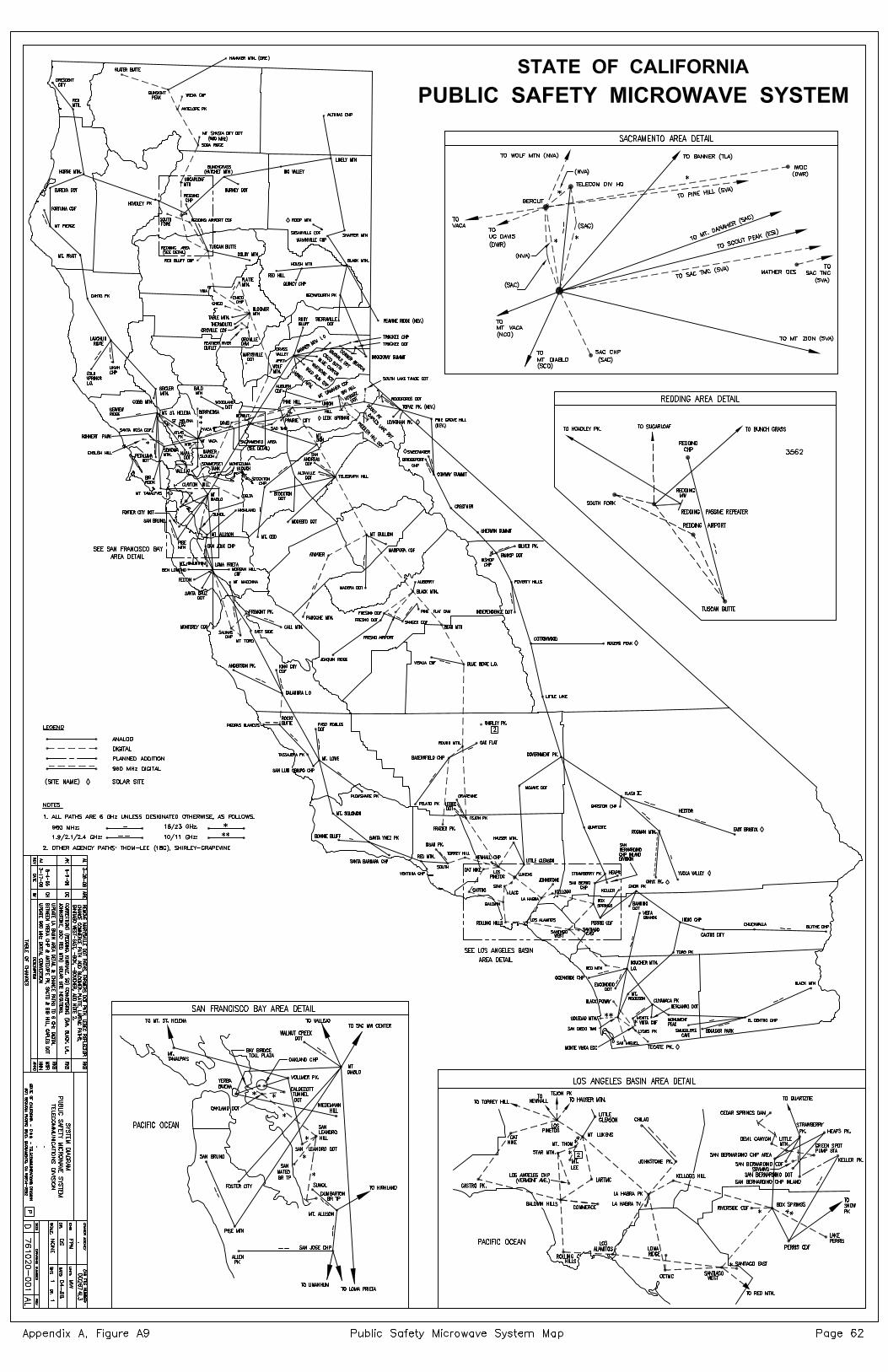
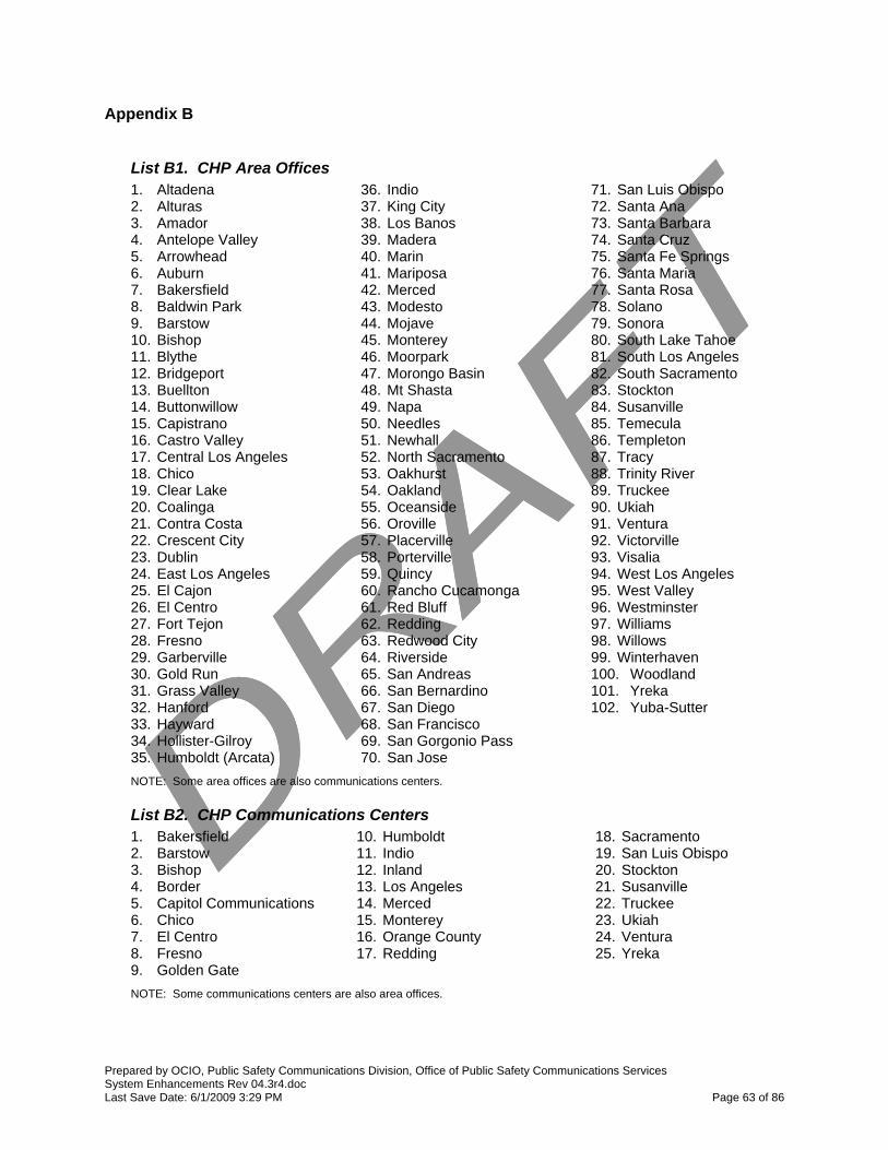
Prepared by OCIO, Public Safety Communications Division, Office of Public Safety Communications Services System Enhancements Rev 04.3r4.doc Last Save Date: 6/1/2009 3:29 PM Page 63 of 86
Appendix B
List B1. CHP Area Offices 1. Altadena 2. Alturas 3. Amador 4. Antelope Valley 5. Arrowhead 6. Auburn 7. Bakersfield 8. Baldwin Park 9. Barstow 10. Bishop 11. Blythe 12. Bridgeport 13. Buellton 14. Buttonwillow 15. Capistrano 16. Castro Valley 17. Central Los Angeles 18. Chico 19. Clear Lake 20. Coalinga 21. Contra Costa 22. Crescent City 23. Dublin 24. East Los Angeles 25. El Cajon 26. El Centro 27. Fort Tejon 28. Fresno 29. Garberville 30. Gold Run 31. Grass Valley 32. Hanford 33. Hayward 34. Hollister-Gilroy 35. Humboldt (Arcata)
36. Indio 37. King City 38. Los Banos 39. Madera 40. Marin 41. Mariposa 42. Merced 43. Modesto 44. Mojave 45. Monterey 46. Moorpark 47. Morongo Basin 48. Mt Shasta 49. Napa 50. Needles 51. Newhall 52. North Sacramento 53. Oakhurst 54. Oakland 55. Oceanside 56. Oroville 57. Placerville 58. Porterville 59. Quincy 60. Rancho Cucamonga 61. Red Bluff 62. Redding 63. Redwood City 64. Riverside 65. San Andreas 66. San Bernardino 67. San Diego 68. San Francisco 69. San Gorgonio Pass 70. San Jose
71. San Luis Obispo 72. Santa Ana 73. Santa Barbara 74. Santa Cruz 75. Santa Fe Springs 76. Santa Maria 77. Santa Rosa 78. Solano 79. Sonora 80. South Lake Tahoe 81. South Los Angeles 82. South Sacramento 83. Stockton 84. Susanville 85. Temecula 86. Templeton 87. Tracy 88. Trinity River 89. Truckee 90. Ukiah 91. Ventura 92. Victorville 93. Visalia 94. West Los Angeles 95. West Valley 96. Westminster 97. Williams 98. Willows 99. Winterhaven 100. Woodland 101. Yreka 102. Yuba-Sutter
NOTE: Some area offices are also communications centers.
List B2. CHP Communications Centers 1. Bakersfield 2. Barstow 3. Bishop 4. Border 5. Capitol Communications 6. Chico 7. El Centro 8. Fresno 9. Golden Gate
10. Humboldt 11. Indio 12. Inland 13. Los Angeles 14. Merced 15. Monterey 16. Orange County 17. Redding
18. Sacramento 19. San Luis Obispo 20. Stockton 21. Susanville 22. Truckee 23. Ukiah 24. Ventura 25. Yreka
NOTE: Some communications centers are also area offices.

Prepared by OCIO, Public Safety Communications Division, Office of Public Safety Communications Services System Enhancements Rev 04.3r4.doc Last Save Date: 6/1/2009 3:29 PM Page 64 of 86
Appendix B – continued
List B3. CHP Inspection Facilities 1. Calexico 2. Castaic 3. Chowchilla River 4. Conejo N/B 5. Conejo S/B 6. Cordelia E/B 7. Cordelia W/B 8. Cottonwood N/B
9. Cottonwood S/B 10. Desert Hills 11. Donner Pass 12. Dunsmuir Grade 13. Gilroy N/B 14. Gilroy S/B 15. Grapevine 16. Mission Grade
17. Nimitz 18. Otay Mesa 19. Rainbow N/B 20. Rainbow S/B 21. San Onofre N/B 22. San Onofre S/B
List B4. CHP Public Scales, Resident Posts and Other Facilities Public Scales 1. Antelope E/B 2. Antelope W/B 3. Blythe 4. Buckhorn 5. Cache Creek 6. Cajon N/B 7. Cajon S/B 8. Camino W/B 9. Carson N/B 10. Carson S/B 11. Keddie 12. Keene 13. Little River 14. Livermore E/B 15. Livermore W/B 16. Lyons Dam W/B 17. Murphys W/B 18. Peralta E/B 19. Peralta W/B 20. Santa Nella N/B 21. Santa Nella S/B 22. Sidewinder Ps 23. St Vincent N/B 24. St Vincent S/B 25. Tecate 26. Terra Linda 27. Two Rock
Resident Posts 1. Big Bear 2. Big Sur 3. Bodega Bay 4. Borrego Springs 5. Burney 6. Camp Nelson 7. Challenge 8. Chester 9. Coleville 10. Death Valley 11. Dorris 12. Downieville 13. Ebbetts Pass 14. Fort Bragg 15. Groveland 16. Happy Camp 17. Indian Valley 18. Inyo Kern 19. Jacumba 20. Julian 21. June Lake 22. Kern Valley 23. Kings River 24. Lake Isabella 25. Laytonville 26. Lee Vining 27. Lone Pine 28. Loyalton 29. Mammoth Lakes 30. Mountain Pass 31. Parker Dam 32. Point Arena 33. Portola 34. Romona 35. Shaver Lake 36. Sonoma Coast 37. Tule Lake
Resident Posts - continued 38. Walnut Grove 39. Willits 40. Willow Creek Other Facilities 1. ACRATT 2. Border Air Operations 3. Central Air Operations 4. Central ISU 5. CHP Academy 6. Coastal Air Operations 7. Coastal ISU 8. Fresno Store Front 9. Golden Gate Air Operations 10. Golden Gate ISU 11. Inland Air Operations 12. Inland CTIP 13. Motor Carrier Bakersfield 14. Motor Carrier Fresno 15. Northern Air Operations 16. Orange County Air Operations 17. SACCATS 18. SJCATS 19. Southern CTIP 20. Valley Air Operations 21. Valley ISU

Prepared by OCIO, Public Safety Communications Division, Office of Public Safety Communications Services System Enhancements Rev 04.3r4.doc Last Save Date: 6/1/2009 3:29 PM Page 65 of 86
Appendix B – continued
List B5. Sites Requiring Facility Upgrades Via the Capital Outlay Process Valley Division 1. Carson Caples 2. Donner Beacon 3. Leviathan Peak 4. Pluto Mt 5. Truckee CC Central Division None Currently Identified
Northern Division 1. Gunsight Peak 2. Hamaker Mt 3. Happy Camp Mtn 4. Humboldt AO 5. Slater Butte 6. Soda Ridge 7. Ukiah CC Coastal Division 1. Anderson Peak 2. Black Mtn (SLO) 3. Dibble Hill 4. Plowshare Peak 5. Tassajara Peak 6. Toro Peak (Monterey) 7. Ventura CC
Inland Division 1. tbd Border Division 1. tbd Southern Division 1. tbd Golden Gate Division 1. tbd
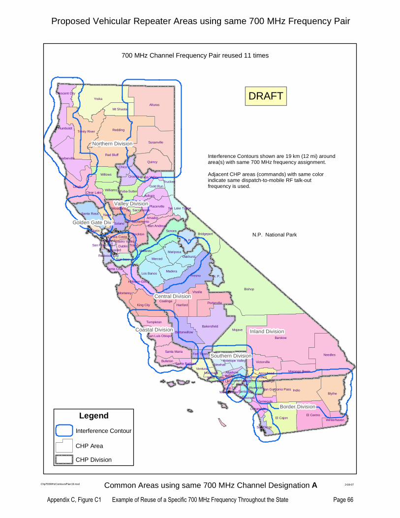
Bishop
Barstow
Yreka
Alturas
Indio
Mojave
Redding
Fresno
Needles
Blythe
Ukiah
El Cajon
Bakersfield
Susanville
Trinity River
Red Bluff
Quincy
El Centro
Bridgeport
N. P.
King City
Sonora
Visalia
Garberville
Buttonwillow
Humboldt
Modesto
Willows
PortervilleCoalinga
Victorville
Monterey
Morongo Basin
Placerville
Auburn
Napa
Los BanosMadera
Ventura
Hanford
N. P.
Williams
Santa Rosa
Chico
Mt Shasta
Merced
Stockton
Santa Maria
Clear Lake
Solano
Templeton
Oroville
Mariposa
Truckee
Hollister-Gilroy
Newhall
Yuba-Sutter
Oakhurst
Woodland
Marin
Dublin
San Andreas
San Jose
Antelope Valley
Winterhaven
San Luis Obispo
Amador
Crescent City
Temecula
Bulleton
Grass Valley
Riverside
Gold Run
Arrowhead
Tracy
Fort Tejon
So. Lake Tahoe
Contra Costa
So. Sacramento
Santa Cruz
San Diego
Oceanside
San Gorgonio Pass
Redwood City
Moorpark
Santa Barbara
San Bernardino
Santa Ana
AltadenaBaldwin Park
South LA
Capistrano
West ValleyWest LA
Hayward
No. Sacramento
Central LA
Westminister
East LARancho Cucamonga
OaklandSan Francisco
Castro Valley
Inland DivisionInland Division
Northern DivisionNorthern Division
Central DivisionCentral Division
Border DivisionBorder Division
Valley DivisionValley Division
Coastal DivisionCoastal Division
Golden Gate Div.Golden Gate Div.
Southern DivisionSouthern Division
Proposed Vehicular Repeater Areas using same 700 MHz Frequency Pair
Interference Contours shown are 19 km (12 mi) aroundarea(s) with same 700 MHz frequency assignment.
Adjacent CHP areas (commands) with same colorindicate same dispatch-to-mobile RF talk-outfrequency is used.
N.P. National Park
Chp700MHzContoursPlan19.mxd 2-08-07
Legend
Interference Contour
CHP Area
CHP Division
DRAFT
700 MHz Channel Frequency Pair reused 11 times
Common Areas using same 700 MHz Channel Designation A
Appendix C, Figure C1 Example of Reuse of a Specific 700 MHz Frequency Throughout the State Page 66

CHP 700 MHz Channel Request
769 MHz ← →
1 2 3 4 5 6 7 8 9 10 11 12 13 14 15 16 17 18 19 20 21 22 23 24 25 26 27 28 29 30 31 32 33 34 35 36 37 38 39 40 41 42 43 44 45 46 47 48 49 50 51 52 53 54 55 56 57 58 59 60 61 62 63 64 65 66 67 68 69 70 71 72 73 74 75 76 77 78 79 80
81 82 83 84 85 86 87 88 89 90 91 92 93 94 95 96 97 98 99 100
101
102
103
104
105
106
107
108
109
110
111
112
113
114
115
116
117
118
119
120
121
122
123
124
125
126
127
128
129
130
131
132
133
134
135
136
137
138
139
140
141
142
143
144
145
146
147
148
149
150
151
152
153
154
155
156
157
158
159
160
770 MHz
161
162
163
164
165
166
167
168
169
170
171
172
173
174
175
176
177
178
179
180
181
182
183
184
185
186
187
188
189
190
191
192
193
194
195
196
197
198
199
200
201
202
203
204
205
206
207
208
209
210
211
212
213
214
215
216
217
218
219
220
221
222
223
224
225
226
227
228
229
230
231
232
233
234
235
236
237
238
239
240
241
242
243
244
245
246
247
248
249
250
251
252
253
254
255
256
257
258
259
260
261
262
263
264
265
266
267
268
269
270
271
272
273
274
275
276
277
278
279
280
281
282
283
284
285
286
287
288
289
290
291
292
293
294
295
296
297
298
299
300
301
302
303
304
305
306
307
308
309
310
311
312
313
314
315
316
317
318
319
320
771 MHz
321
322
323
324
325
326
327
328
329
330
331
332
333
334
335
336
337
338
339
340
341
342
343
344
345
346
347
348
349
350
351
352
353
354
355
356
357
358
359
360
361
362
363
364
365
366
367
368
369
370
371
372
373
374
375
376
377
378
379
380
381
382
383
384
385
386
387
388
389
390
391
392
393
394
395
396
397
398
399
400
401
402
403
404
405
406
407
408
409
410
411
412
413
414
415
416
417
418
419
420
421
422
423
424
425
426
427
428
429
430
431
432
433
434
435
436
437
438
439
440
441
442
443
444
445
446
447
448
449
450
451
452
453
454
455
456
457
458
459
460
461
462
463
464
465
466
467
468
469
470
471
472
473
474
475
476
477
478
479
480
772 MHz
481
482
483
484
485
486
487
488
489
490
491
492
493
494
495
496
497
498
499
500
501
502
503
504
505
506
507
508
509
510
511
512
513
514
515
516
517
518
519
520
521
522
523
524
525
526
527
528
529
530
531
532
533
534
535
536
537
538
539
540
541
542
543
544
545
546
547
548
549
550
551
552
553
554
555
556
557
558
559
560
561
562
563
564
565
566
567
568
569
570
571
572
573
574
575
576
577
578
579
580
581
582
583
584
585
586
587
588
589
590
591
592
593
594
595
596
597
598
599
600
601
602
603
604
605
606
607
608
609
610
611
612
613
614
615
616
617
618
619
620
621
622
623
624
625
626
627
628
629
630
631
632
633
634
635
636
637
638
639
640
773 MHz
641
642
643
644
645
646
647
648
649
650
651
652
653
654
655
656
657
658
659
660
661
662
663
664
665
666
667
668
669
670
671
672
673
674
675
676
677
678
679
680
681
682
683
684
685
686
687
688
689
690
691
692
693
694
695
696
697
698
699
700
701
702
703
704
705
706
707
708
709
710
711
712
713
714
715
716
717
718
719
720
721
722
723
724
725
726
727
728
729
730
731
732
733
734
735
736
737
738
739
740
741
742
743
744
745
746
747
748
749
750
751
752
753
754
755
756
757
758
759
760
761
762
763
764
765
766
767
768
769
770
771
772
773
774
775
776
777
778
779
780
781
782
783
784
785
786
787
788
789
790
791
792
793
794
795
796
797
798
799
800
774 MHz
801
802
803
804
805
806
807
808
809
810
811
812
813
814
815
816
817
818
819
820
821
822
823
824
825
826
827
828
829
830
831
832
833
834
835
836
837
838
839
840
841
842
843
844
845
846
847
848
849
850
851
852
853
854
855
856
857
858
859
860
861
862
863
864
865
866
867
868
869
870
871
872
873
874
875
876
877
878
879
880
881
882
883
884
885
886
887
888
889
890
891
892
893
894
895
896
897
898
899
900
901
902
903
904
905
906
907
908
909
910
911
912
913
914
915
916
917
918
919
920
921
922
923
924
925
926
927
928
929
930
931
932
933
934
935
936
937
938
939
940
941
942
943
944
945
946
947
948
949
950
951
952
953
954
955
956
957
958
959
960
775 MHz
NARROWBAND CHANNELS: Two may be combined provided that the lower channel number is odd (e.g., 1, 3, 5)Four may be combined provided that the lower channel number is 1 + 4n, n = 0 to 479 (e.g., 1, 5,…1917)Channel numbers for combined channels are designated by the lowest and highest channel numbers separated by a hyphen, e.g., "1-2" and 1-4".Narrowband channels must maintain a data throughput efficiency of not less than 4.8 kbps for each 6.25 kHz of bandwidth.
NOTE:
Basic band plan configuration revised per FCC PS Docket 06-229
Adopted From: 700 MHz BAND PLAN per Second R&O of PS Docket 06-229
----
----
----
----
----
----
----
----
----
TV
Ch
64 --
----
----
----
----
----
----
----
----
----
TV
Ch
63 --
CHP GENERAL USE
960 NARROWBAND BASE CHANNELS - (6.25 kHz each, aggregate to 25 kHz)
700 MHz BAND PLAN - Base Channels
INTEROPERABILITY
RESERVE
As an example, a single 12.5 kHz channel is made up of two adjacent 6.25 kHz channel allocations (25-26) from Segment 1 for “base” or "vehicular repeater" transmit that is paired with FCC defined adjacent channel allocations (985-986) from Segment 3 for “mobile” or "portable" transmit.
I/O Low Speed DATA
SEG
MEN
T 1
SEG
MEN
T 2
I/O Nationwide CALL
LOW POWER
STATE LICENSE
2ndary TRUNKING
Revised 7/30/08 700_CaStatePlan2c.xls
Appendix C, Figure C2 Base Station Channels – 700 MHz Public Safety Band Page 67
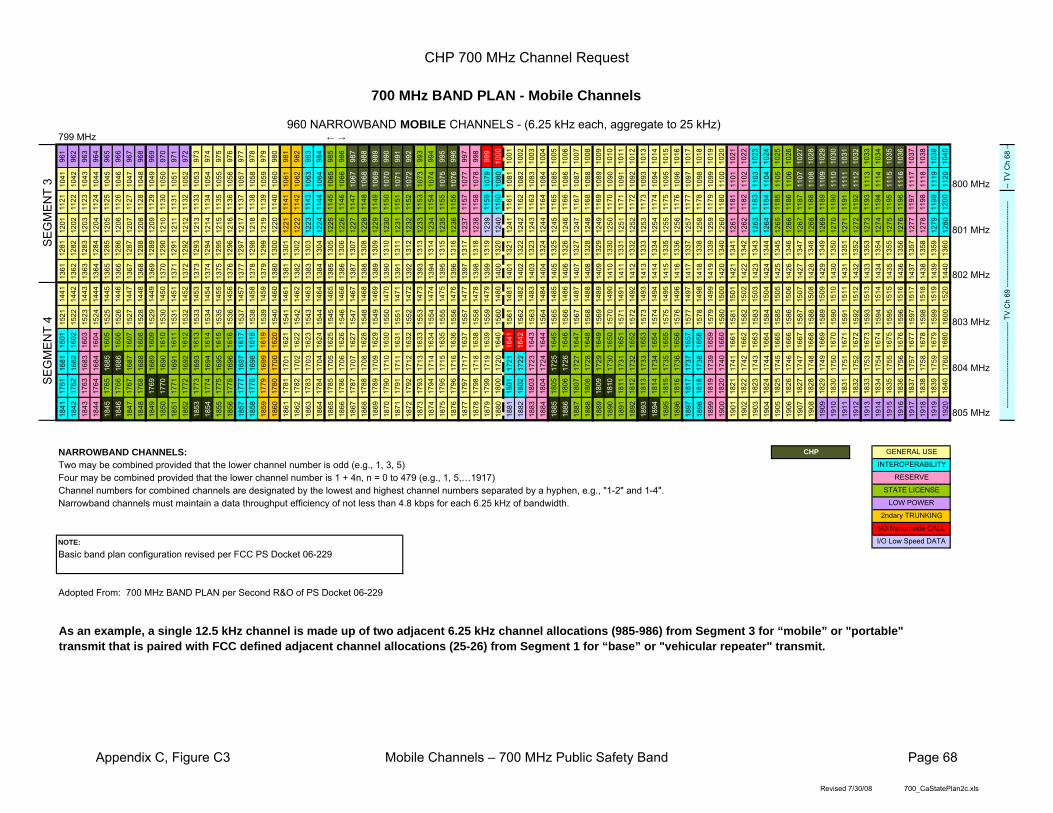
CHP 700 MHz Channel Request
799 MHz ← →
961
962
963
964
965
966
967
968
969
970
971
972
973
974
975
976
977
978
979
980
981
982
983
984
985
986
987
988
989
990
991
992
993
994
995
996
997
998
999
1000
1001
1002
1003
1004
1005
1006
1007
1008
1009
1010
1011
1012
1013
1014
1015
1016
1017
1018
1019
1020
1021
1022
1023
1024
1025
1026
1027
1028
1029
1030
1031
1032
1033
1034
1035
1036
1037
1038
1039
1040
1041
1042
1043
1044
1045
1046
1047
1048
1049
1050
1051
1052
1053
1054
1055
1056
1057
1058
1059
1060
1061
1062
1063
1064
1065
1066
1067
1068
1069
1070
1071
1072
1073
1074
1075
1076
1077
1078
1079
1080
1081
1082
1083
1084
1085
1086
1087
1088
1089
1090
1091
1092
1093
1094
1095
1096
1097
1098
1099
1100
1101
1102
1103
1104
1105
1106
1107
1108
1109
1110
1111
1112
1113
1114
1115
1116
1117
1118
1119
1120
800 MHz
1121
1122
1123
1124
1125
1126
1127
1128
1129
1130
1131
1132
1133
1134
1135
1136
1137
1138
1139
1140
1141
1142
1143
1144
1145
1146
1147
1148
1149
1150
1151
1152
1153
1154
1155
1156
1157
1158
1159
1160
1161
1162
1163
1164
1165
1166
1167
1168
1169
1170
1171
1172
1173
1174
1175
1176
1177
1178
1179
1180
1181
1182
1183
1184
1185
1186
1187
1188
1189
1190
1191
1192
1193
1194
1195
1196
1197
1198
1199
1200
1201
1202
1203
1204
1205
1206
1207
1208
1209
1210
1211
1212
1213
1214
1215
1216
1217
1218
1219
1220
1221
1222
1223
1224
1225
1226
1227
1228
1229
1230
1231
1232
1233
1234
1235
1236
1237
1238
1239
1240
1241
1242
1243
1244
1245
1246
1247
1248
1249
1250
1251
1252
1253
1254
1255
1256
1257
1258
1259
1260
1261
1262
1263
1264
1265
1266
1267
1268
1269
1270
1271
1272
1273
1274
1275
1276
1277
1278
1279
1280
801 MHz
1281
1282
1283
1284
1285
1286
1287
1288
1289
1290
1291
1292
1293
1294
1295
1296
1297
1298
1299
1300
1301
1302
1303
1304
1305
1306
1307
1308
1309
1310
1311
1312
1313
1314
1315
1316
1317
1318
1319
1320
1321
1322
1323
1324
1325
1326
1327
1328
1329
1330
1331
1332
1333
1334
1335
1336
1337
1338
1339
1340
1341
1342
1343
1344
1345
1346
1347
1348
1349
1350
1351
1352
1353
1354
1355
1356
1357
1358
1359
1360
1361
1362
1363
1364
1365
1366
1367
1368
1369
1370
1371
1372
1373
1374
1375
1376
1377
1378
1379
1380
1381
1382
1383
1384
1385
1386
1387
1388
1389
1390
1391
1392
1393
1394
1395
1396
1397
1398
1399
1400
1401
1402
1403
1404
1405
1406
1407
1408
1409
1410
1411
1412
1413
1414
1415
1416
1417
1418
1419
1420
1421
1422
1423
1424
1425
1426
1427
1428
1429
1430
1431
1432
1433
1434
1435
1436
1437
1438
1439
1440
802 MHz
1441
1442
1443
1444
1445
1446
1447
1448
1449
1450
1451
1452
1453
1454
1455
1456
1457
1458
1459
1460
1461
1462
1463
1464
1465
1466
1467
1468
1469
1470
1471
1472
1473
1474
1475
1476
1477
1478
1479
1480
1481
1482
1483
1484
1485
1486
1487
1488
1489
1490
1491
1492
1493
1494
1495
1496
1497
1498
1499
1500
1501
1502
1503
1504
1505
1506
1507
1508
1509
1510
1511
1512
1513
1514
1515
1516
1517
1518
1519
1520
1521
1522
1523
1524
1525
1526
1527
1528
1529
1530
1531
1532
1533
1534
1535
1536
1537
1538
1539
1540
1541
1542
1543
1544
1545
1546
1547
1548
1549
1550
1551
1552
1553
1554
1555
1556
1557
1558
1559
1560
1561
1562
1563
1564
1565
1566
1567
1568
1569
1570
1571
1572
1573
1574
1575
1576
1577
1578
1579
1580
1581
1582
1583
1584
1585
1586
1587
1588
1589
1590
1591
1592
1593
1594
1595
1596
1597
1598
1599
1600
803 MHz
1601
1602
1603
1604
1605
1606
1607
1608
1609
1610
1611
1612
1613
1614
1615
1616
1617
1618
1619
1620
1621
1622
1623
1624
1625
1626
1627
1628
1629
1630
1631
1632
1633
1634
1635
1636
1637
1638
1639
1640
1641
1642
1643
1644
1645
1646
1647
1648
1649
1650
1651
1652
1653
1654
1655
1656
1657
1658
1659
1660
1661
1662
1663
1664
1665
1666
1667
1668
1669
1670
1671
1672
1673
1674
1675
1676
1677
1678
1679
1680
1681
1682
1683
1684
1685
1686
1687
1688
1689
1690
1691
1692
1693
1694
1695
1696
1697
1698
1699
1700
1701
1702
1703
1704
1705
1706
1707
1708
1709
1710
1711
1712
1713
1714
1715
1716
1717
1718
1719
1720
1721
1722
1723
1724
1725
1726
1727
1728
1729
1730
1731
1732
1733
1734
1735
1736
1737
1738
1739
1740
1741
1742
1743
1744
1745
1746
1747
1748
1749
1750
1751
1752
1753
1754
1755
1756
1757
1758
1759
1760
804 MHz
1761
1762
1763
1764
1765
1766
1767
1768
1769
1770
1771
1772
1773
1774
1775
1776
1777
1778
1779
1780
1781
1782
1783
1784
1785
1786
1787
1788
1789
1790
1791
1792
1793
1794
1795
1796
1797
1798
1799
1800
1801
1802
1803
1804
1805
1806
1807
1808
1809
1810
1811
1812
1813
1814
1815
1816
1817
1818
1819
1820
1821
1822
1823
1824
1825
1826
1827
1828
1829
1830
1831
1832
1833
1834
1835
1836
1837
1838
1839
1840
1841
1842
1843
1844
1845
1846
1847
1848
1849
1850
1851
1852
1853
1854
1855
1856
1857
1858
1859
1860
1861
1862
1863
1864
1865
1866
1867
1868
1869
1870
1871
1872
1873
1874
1875
1876
1877
1878
1879
1880
1881
1882
1883
1884
1885
1886
1887
1888
1889
1890
1891
1892
1893
1894
1895
1896
1897
1898
1899
1900
1901
1902
1903
1904
1905
1906
1907
1908
1909
1910
1911
1912
1913
1914
1915
1916
1917
1918
1919
1920
805 MHz
NARROWBAND CHANNELS: Two may be combined provided that the lower channel number is odd (e.g., 1, 3, 5)Four may be combined provided that the lower channel number is 1 + 4n, n = 0 to 479 (e.g., 1, 5,…1917)Channel numbers for combined channels are designated by the lowest and highest channel numbers separated by a hyphen, e.g., "1-2" and 1-4".Narrowband channels must maintain a data throughput efficiency of not less than 4.8 kbps for each 6.25 kHz of bandwidth.
NOTE:
Basic band plan configuration revised per FCC PS Docket 06-229
Adopted From: 700 MHz BAND PLAN per Second R&O of PS Docket 06-229
SEG
MEN
T 3
SEG
MEN
T 4
CHP GENERAL USE
700 MHz BAND PLAN - Mobile Channels
2ndary TRUNKING
I/O Nationwide CALL
I/O Low Speed DATA
INTEROPERABILITY
RESERVE
STATE LICENSE
LOW POWER
As an example, a single 12.5 kHz channel is made up of two adjacent 6.25 kHz channel allocations (985-986) from Segment 3 for “mobile” or "portable" transmit that is paired with FCC defined adjacent channel allocations (25-26) from Segment 1 for “base” or "vehicular repeater" transmit.
-- T
V C
h 68
----
----
----
----
----
----
----
----
----
-- T
V C
h 69
----
----
----
----
----
----
----
----
----
960 NARROWBAND MOBILE CHANNELS - (6.25 kHz each, aggregate to 25 kHz)
Revised 7/30/08 700_CaStatePlan2c.xls
Appendix C, Figure C3 Mobile Channels – 700 MHz Public Safety Band Page 68

Public Safety Low Band VHF Frequency PoolPortion of Spectrum from 39 - 46.6 MHz
0
1
2
3
4
5
6
7
8
9
10
39.0
0
39.2
0
39.4
0
39.6
0
39.8
0
40.0
0
40.2
0
40.4
0
40.6
0
40.8
0
41.0
0
41.2
0
41.4
0
41.6
0
41.8
0
42.0
0
42.2
0
42.4
0
42.6
0
42.8
0
43.0
0
43.2
0
43.4
0
43.6
0
43.8
0
44.0
0
44.2
0
44.4
0
44.6
0
44.8
0
45.0
0
45.2
0
45.4
0
45.6
0
45.8
0
46.0
0
46.2
0
46.4
0
46.6
0
Frequency (MHz)
Freq
uenc
y C
oord
inat
or C
ateg
ory
Height Represents Corresponding Frequency Coordinator Category
Freq Coordinator Category 7 PP Police 6 PS Special Emergency 5 PO Forestry-Conservation 4 PX All, except PS 3 PH Highway Maintenance 2 PF FireGreen - CHP existing use (some frequencies licensed in So Cal, only)
Non-integer height - FCC defined frequency as Mobile-Only operation
HighestNational Plan
frequency45.06
Appendix C, Figure C4 Frequency Overview of Lowband VHF Frequencies Analyzed Page 69

Appendix C, Figure C5Factors Included in Lowband VHF Frequency Analysis Includes Multiple Frequency Searches of Existing FCC Licensed Users by Frequency Page 70
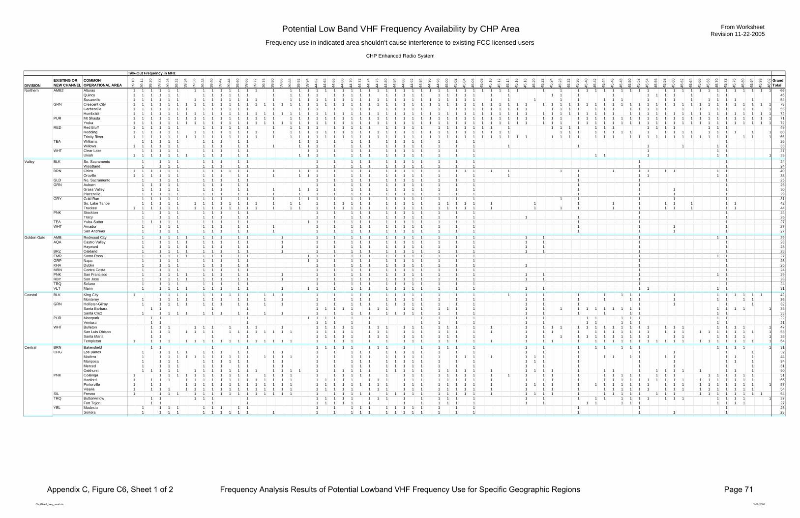
Potential Low Band VHF Frequency Availability by CHP AreaFrequency use in indicated area shouldn't cause interference to existing FCC licensed users
CHP Enhanced Radio System
From WorksheetRevision 11-22-2005
Talk-Out Frequency in MHz
DIVISIONEXISTING ORNEW CHANNEL
COMMONOPERATIONAL AREA 39
.10
39.1
4
39.2
0
39.2
2
39.2
6
39.3
2
39.3
4
39.3
6
39.3
8
39.4
0
39.4
2
39.4
4
39.6
0
39.6
6
39.7
2
39.7
6
39.8
0
39.8
6
39.8
8
39.9
2
39.9
4
44.6
2
44.6
4
44.6
6
44.6
8
44.7
0
44.7
2
44.7
4
44.7
6
44.8
0
44.8
4
44.8
8
44.9
2
44.9
4
44.9
6
44.9
8
45.0
0
45.0
2
45.0
4
45.0
6
45.0
8
45.1
0
45.1
2
45.1
4
45.1
6
45.1
8
45.2
0
45.2
2
45.2
4
45.2
8
45.3
2
45.3
6
45.4
0
45.4
2
45.4
4
45.4
6
45.4
8
45.5
0
45.5
2
45.5
4
45.5
6
45.5
8
45.6
0
45.6
2
45.6
4
45.6
6
45.6
8
45.7
0
45.7
2
45.7
6
45.8
0
45.9
4
45.9
8
46.0
2 GrandTotal
Northern AMB2 Alturas 1 1 1 1 1 1 1 1 1 1 1 1 1 1 1 1 1 1 1 1 1 1 1 1 1 1 1 1 1 1 1 1 1 1 1 1 1 1 1 1 1 1 1 1 1 1 1 1 1 1 1 1 1 1 1 1 1 1 1 1 1 1 1 1 1 1 66Quincy 1 1 1 1 1 1 1 1 1 1 1 1 1 1 1 1 1 1 1 1 1 1 1 1 1 1 1 1 1 1 1 1 1 1 1 1 1 1 1 1 1 1 1 1 1 45Susanville 1 1 1 1 1 1 1 1 1 1 1 1 1 1 1 1 1 1 1 1 1 1 1 1 1 1 1 1 1 1 1 1 1 1 1 1 1 1 1 1 1 1 1 1 1 1 1 1 1 1 1 1 1 1 54
GRN Crescent City 1 1 1 1 1 1 1 1 1 1 1 1 1 1 1 1 1 1 1 1 1 1 1 1 1 1 1 1 1 1 1 1 1 1 1 1 1 1 1 1 1 1 1 1 1 1 1 1 1 1 1 1 1 1 1 1 1 1 1 1 1 1 1 1 1 1 1 1 1 1 1 1 1 73Garberville 1 1 1 1 1 1 1 1 1 1 1 1 1 1 1 1 1 1 1 1 1 1 1 1 1 1 1 1 1 1 1 1 1 1 1 1 1 1 1 1 1 1 1 1 1 1 1 1 1 1 1 1 1 1 1 55Humboldt 1 1 1 1 1 1 1 1 1 1 1 1 1 1 1 1 1 1 1 1 1 1 1 1 1 1 1 1 1 1 1 1 1 1 1 1 1 1 1 1 1 1 1 1 1 1 1 1 1 1 1 1 1 1 1 1 1 1 1 1 1 1 1 1 1 1 1 1 1 1 1 1 72
PUR Mt Shasta 1 1 1 1 1 1 1 1 1 1 1 1 1 1 1 1 1 1 1 1 1 1 1 1 1 1 1 1 1 1 1 1 1 1 1 1 1 1 1 1 1 1 1 1 1 1 1 1 1 1 1 1 1 1 1 1 1 1 1 1 1 1 1 1 1 1 1 1 1 1 1 71Yreka 1 1 1 1 1 1 1 1 1 1 1 1 1 1 1 1 1 1 1 1 1 1 1 1 1 1 1 1 1 1 1 1 1 1 1 1 1 1 1 1 1 1 1 1 1 1 1 1 1 1 1 1 1 1 1 1 1 1 1 1 1 1 1 1 1 1 1 1 1 1 1 1 72
RED Red Bluff 1 1 1 1 1 1 1 1 1 1 1 1 1 1 1 1 1 1 1 1 1 1 1 1 1 1 1 1 1 1 1 1 1 1 1 1 1 1 1 1 1 1 1 1 1 1 1 1 1 49Redding 1 1 1 1 1 1 1 1 1 1 1 1 1 1 1 1 1 1 1 1 1 1 1 1 1 1 1 1 1 1 1 1 1 1 1 1 1 1 1 1 1 1 1 1 1 1 1 1 1 1 1 1 1 1 1 1 1 1 1 1 60Trinity River 1 1 1 1 1 1 1 1 1 1 1 1 1 1 1 1 1 1 1 1 1 1 1 1 1 1 1 1 1 1 1 1 1 1 1 1 1 1 1 1 1 1 1 1 1 1 1 1 1 1 1 1 1 1 1 1 1 1 1 1 1 1 1 1 1 1 66
TEA Williams 1 1 1 1 1 1 1 1 1 1 1 1 1 1 1 1 1 1 1 1 1 1 1 1 1 1 26Willows 1 1 1 1 1 1 1 1 1 1 1 1 1 1 1 1 1 1 1 1 1 1 1 1 1 1 1 1 1 1 1 1 1 33
WHT Clear Lake 1 1 1 1 1 1 1 1 1 1 1 1 1 1 1 1 1 1 1 1 1 1 1 1 1 1 1 27Ukiah 1 1 1 1 1 1 1 1 1 1 1 1 1 1 1 1 1 1 1 1 1 1 1 1 1 1 1 1 1 1 1 1 1 33
Valley BLK So. Sacramento 1 1 1 1 1 1 1 1 1 1 1 1 1 1 1 1 1 1 1 1 1 1 1 1 24Woodland 1 1 1 1 1 1 1 1 1 1 1 1 1 1 1 1 1 1 1 1 1 1 1 1 24
BRN Chico 1 1 1 1 1 1 1 1 1 1 1 1 1 1 1 1 1 1 1 1 1 1 1 1 1 1 1 1 1 1 1 1 1 1 1 1 1 1 1 1 40Oroville 1 1 1 1 1 1 1 1 1 1 1 1 1 1 1 1 1 1 1 1 1 1 1 1 1 1 1 1 1 1 1 1 1 33
GLD No. Sacramento 1 1 1 1 1 1 1 1 1 1 1 1 1 1 1 1 1 1 1 1 1 1 1 1 1 25GRN Auburn 1 1 1 1 1 1 1 1 1 1 1 1 1 1 1 1 1 1 1 1 1 1 1 1 1 1 26
Grass Valley 1 1 1 1 1 1 1 1 1 1 1 1 1 1 1 1 1 1 1 1 1 1 1 1 1 1 1 1 1 1 30Placerville 1 1 1 1 1 1 1 1 1 1 1 1 1 1 1 1 1 1 1 1 1 1 1 1 1 1 1 1 1 29
GRY Gold Run 1 1 1 1 1 1 1 1 1 1 1 1 1 1 1 1 1 1 1 1 1 1 1 1 1 1 1 1 1 1 1 31So. Lake Tahoe 1 1 1 1 1 1 1 1 1 1 1 1 1 1 1 1 1 1 1 1 1 1 1 1 1 1 1 1 1 1 1 1 1 1 1 1 1 1 1 1 1 1 42Truckee 1 1 1 1 1 1 1 1 1 1 1 1 1 1 1 1 1 1 1 1 1 1 1 1 1 1 1 1 1 1 1 1 1 1 1 1 1 1 1 1 1 1 1 1 44
PNK Stockton 1 1 1 1 1 1 1 1 1 1 1 1 1 1 1 1 1 1 1 1 1 1 1 1 24Tracy 1 1 1 1 1 1 1 1 1 1 1 1 1 1 1 1 1 1 1 1 1 1 1 1 1 1 26
TEA Yuba-Sutter 1 1 1 1 1 1 1 1 1 1 1 1 1 1 1 1 1 1 1 1 1 1 1 1 1 1 1 27WHT Amador 1 1 1 1 1 1 1 1 1 1 1 1 1 1 1 1 1 1 1 1 1 1 1 1 1 1 1 27
San Andreas 1 1 1 1 1 1 1 1 1 1 1 1 1 1 1 1 1 1 1 1 1 1 1 1 1 1 1 27
Golden Gate AMB Redwood City 1 1 1 1 1 1 1 1 1 1 1 1 1 1 1 1 1 1 1 1 1 1 1 1 1 1 1 1 1 29AQA Castro Valley 1 1 1 1 1 1 1 1 1 1 1 1 1 1 1 1 1 1 1 1 1 1 1 1 1 1 1 1 28
Hayward 1 1 1 1 1 1 1 1 1 1 1 1 1 1 1 1 1 1 1 1 1 1 1 1 1 1 1 1 28BRZ Oakland 1 1 1 1 1 1 1 1 1 1 1 1 1 1 1 1 1 1 1 1 1 1 1 1 1 1 1 1 28EMR Santa Rosa 1 1 1 1 1 1 1 1 1 1 1 1 1 1 1 1 1 1 1 1 1 1 1 1 1 1 1 27GRP Napa 1 1 1 1 1 1 1 1 1 1 1 1 1 1 1 1 1 1 1 1 1 1 1 1 1 25KHA Dublin 1 1 1 1 1 1 1 1 1 1 1 1 1 1 1 1 1 1 1 1 1 1 1 1 1 25MRN Contra Costa 1 1 1 1 1 1 1 1 1 1 1 1 1 1 1 1 1 1 1 1 1 1 1 1 24PNK San Francisco 1 1 1 1 1 1 1 1 1 1 1 1 1 1 1 1 1 1 1 1 1 1 1 1 1 1 1 1 1 29RBY San Jose 1 1 1 1 1 1 1 1 1 1 1 1 1 1 1 1 1 1 1 1 1 1 1 1 1 1 1 1 28TRQ Solano 1 1 1 1 1 1 1 1 1 1 1 1 1 1 1 1 1 1 1 1 1 1 1 1 24VLT Marin 1 1 1 1 1 1 1 1 1 1 1 1 1 1 1 1 1 1 1 1 1 1 1 1 1 1 1 1 1 1 1 31
Coastal BLK King City 1 1 1 1 1 1 1 1 1 1 1 1 1 1 1 1 1 1 1 1 1 1 1 1 1 1 1 1 1 1 1 1 1 1 1 1 1 1 1 1 1 1 42Monterey 1 1 1 1 1 1 1 1 1 1 1 1 1 1 1 1 1 1 1 1 1 1 1 1 1 1 1 1 1 1 1 1 1 1 1 1 36
GRN Hollister-Gilroy 1 1 1 1 1 1 1 1 1 1 1 1 1 1 1 1 1 1 1 1 1 1 1 1 1 1 1 1 1 1 1 1 32Santa Barbara 1 1 1 1 1 1 1 1 1 1 1 1 1 1 1 1 1 1 1 1 1 1 1 1 1 1 1 1 1 1 1 1 1 1 1 35Santa Cruz 1 1 1 1 1 1 1 1 1 1 1 1 1 1 1 1 1 1 1 1 1 1 1 1 1 1 1 1 1 1 1 1 1 33
PUR Moorpark 1 1 1 1 1 1 1 1 1 1 1 1 1 1 1 1 1 1 1 1 1 1 22Ventura 1 1 1 1 1 1 1 1 1 1 1 1 1 1 1 1 1 1 1 1 1 21
WHT Bulleton 1 1 1 1 1 1 1 1 1 1 1 1 1 1 1 1 1 1 1 1 1 1 1 1 1 1 1 1 1 1 1 1 1 1 1 1 1 1 1 1 1 1 1 1 1 1 1 47San Luis Obispo 1 1 1 1 1 1 1 1 1 1 1 1 1 1 1 1 1 1 1 1 1 1 1 1 1 1 1 1 1 1 1 1 1 1 1 1 1 1 1 1 1 1 1 1 1 1 1 1 1 1 1 1 1 53Santa Maria 1 1 1 1 1 1 1 1 1 1 1 1 1 1 1 1 1 1 1 1 1 1 1 1 1 1 1 1 1 1 1 1 1 1 1 1 1 1 38Templeton 1 1 1 1 1 1 1 1 1 1 1 1 1 1 1 1 1 1 1 1 1 1 1 1 1 1 1 1 1 1 1 1 1 1 1 1 1 1 1 1 1 1 1 1 1 1 1 1 1 1 1 1 1 1 54
Central BRN Bakersfield 1 1 1 1 1 1 1 1 1 1 1 1 1 1 1 1 1 1 1 1 1 1 1 1 1 1 1 1 1 1 1 31ORG Los Banos 1 1 1 1 1 1 1 1 1 1 1 1 1 1 1 1 1 1 1 1 1 1 1 1 1 1 1 1 1 1 1 1 32
Madera 1 1 1 1 1 1 1 1 1 1 1 1 1 1 1 1 1 1 1 1 1 1 1 1 1 1 1 1 1 1 1 1 1 1 1 1 1 1 1 1 1 1 1 1 44Mariposa 1 1 1 1 1 1 1 1 1 1 1 1 1 1 1 1 1 1 1 1 1 1 1 1 1 1 1 1 1 1 1 1 1 1 34Merced 1 1 1 1 1 1 1 1 1 1 1 1 1 1 1 1 1 1 1 1 1 1 1 1 1 1 1 1 1 1 1 31Oakhurst 1 1 1 1 1 1 1 1 1 1 1 1 1 1 1 1 1 1 1 1 1 1 1 1 1 1 1 1 1 1 1 1 1 1 1 1 1 1 1 1 1 1 1 1 1 1 1 1 1 1 50
PNK Coalinga 1 1 1 1 1 1 1 1 1 1 1 1 1 1 1 1 1 1 1 1 1 1 1 1 1 1 1 1 1 1 1 1 1 1 1 1 1 1 1 1 1 1 1 1 1 1 1 1 1 1 1 51Hanford 1 1 1 1 1 1 1 1 1 1 1 1 1 1 1 1 1 1 1 1 1 1 1 1 1 1 1 1 1 1 1 1 1 1 1 1 1 1 1 1 1 1 1 1 1 1 1 1 1 1 1 1 1 1 1 55Porterville 1 1 1 1 1 1 1 1 1 1 1 1 1 1 1 1 1 1 1 1 1 1 1 1 1 1 1 1 1 1 1 1 1 1 1 1 1 1 1 1 1 1 1 1 1 1 1 1 1 1 1 1 1 1 1 1 1 57Visalia 1 1 1 1 1 1 1 1 1 1 1 1 1 1 1 1 1 1 1 1 1 1 1 1 1 1 1 1 1 1 1 1 1 1 1 1 1 1 1 1 1 1 1 1 1 1 1 1 1 1 1 1 1 1 54
SIL Fresno 1 1 1 1 1 1 1 1 1 1 1 1 1 1 1 1 1 1 1 1 1 1 1 1 1 1 1 1 1 1 1 1 1 1 1 1 1 1 1 1 1 1 1 1 1 1 1 1 1 1 1 1 1 1 54TRQ Buttonwillow 1 1 1 1 1 1 1 1 1 1 1 1 1 1 1 1 1 1 1 1 1 1 1 1 1 1 1 1 1 1 1 1 1 1 1 1 1 37
Fort Tejon 1 1 1 1 1 1 1 1 1 1 1 1 1 1 1 1 1 1 1 1 1 1 1 1 1 1 1 27YEL Modesto 1 1 1 1 1 1 1 1 1 1 1 1 1 1 1 1 1 1 1 1 1 1 1 1 1 25
Sonora 1 1 1 1 1 1 1 1 1 1 1 1 1 1 1 1 1 1 1 1 1 1 1 1 1 1 1 1 28
ChpPlan2_freq_avail.xls 3-02-2006
Appendix C, Figure C6, Sheet 1 of 2 Frequency Analysis Results of Potential Lowband VHF Frequency Use for Specific Geographic Regions Page 71
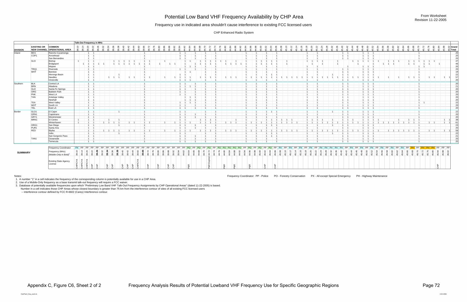
Potential Low Band VHF Frequency Availability by CHP AreaFrequency use in indicated area shouldn't cause interference to existing FCC licensed users
CHP Enhanced Radio System
From WorksheetRevision 11-22-2005
Talk-Out Frequency in MHz
DIVISIONEXISTING ORNEW CHANNEL
COMMONOPERATIONAL AREA 39
.10
39.1
4
39.2
0
39.2
2
39.2
6
39.3
2
39.3
4
39.3
6
39.3
8
39.4
0
39.4
2
39.4
4
39.6
0
39.6
6
39.7
2
39.7
6
39.8
0
39.8
6
39.8
8
39.9
2
39.9
4
44.6
2
44.6
4
44.6
6
44.6
8
44.7
0
44.7
2
44.7
4
44.7
6
44.8
0
44.8
4
44.8
8
44.9
2
44.9
4
44.9
6
44.9
8
45.0
0
45.0
2
45.0
4
45.0
6
45.0
8
45.1
0
45.1
2
45.1
4
45.1
6
45.1
8
45.2
0
45.2
2
45.2
4
45.2
8
45.3
2
45.3
6
45.4
0
45.4
2
45.4
4
45.4
6
45.4
8
45.5
0
45.5
2
45.5
4
45.5
6
45.5
8
45.6
0
45.6
2
45.6
4
45.6
6
45.6
8
45.7
0
45.7
2
45.7
6
45.8
0
45.9
4
45.9
8
46.0
2 GrandTotal
Inland BEI1 Rancho Cucamonga 1 1 1 1 1 1 1 1 1 1 1 1 1 1 1 1 1 1 1 1 20COP1 Arrowhead 1 1 1 1 1 1 1 1 1 1 1 1 1 1 1 1 1 1 1 1 20
San Bernardino 1 1 1 1 1 1 1 1 1 1 1 1 1 1 1 1 1 1 1 1 20GLD Bishop 1 1 1 1 1 1 1 1 1 1 1 1 1 1 1 1 1 1 1 1 1 1 1 1 1 1 1 1 1 1 1 1 1 1 1 1 1 1 1 1 1 1 1 1 1 1 1 47
Bridgeport 1 1 1 1 1 1 1 1 1 1 1 1 1 1 1 1 1 1 1 1 1 1 1 1 1 1 1 1 1 1 1 1 1 1 1 1 1 1 1 1 1 1 1 1 1 1 46Mojave 1 1 1 1 1 1 1 1 1 1 1 1 1 1 1 1 1 1 1 1 20
TRQ1 Riverside 1 1 1 1 1 1 1 1 1 1 1 1 1 1 1 1 1 1 1 1 20WHT Barstow 1 1 1 1 1 1 1 1 1 1 1 1 1 1 1 1 1 1 1 19
Morongo Basin 1 1 1 1 1 1 1 1 1 1 1 1 1 1 1 1 1 1 1 1 1 1 22Needles 1 1 1 1 1 1 1 1 1 1 1 1 1 1 1 1 1 1 1 1 1 1 1 1 1 1 1 1 1 1 1 1 1 1 1 1 1 1 1 1 1 1 1 1 1 1 1 1 1 1 1 1 1 1 1 1 1 57Victorville 1 1 1 1 1 1 1 1 1 1 1 1 1 1 1 1 1 1 1 1 20
Southern BLK Central LA 1 1 1 1 1 1 1 1 1 1 1 1 1 1 1 1 1 1 1 1 20BRN Altadena 1 1 1 1 1 1 1 1 1 1 1 1 1 1 1 1 1 1 1 1 1 21GLD Santa Fe Springs 1 1 1 1 1 1 1 1 1 1 1 1 1 1 1 1 1 1 1 1 20ORG Baldwin Park 1 1 1 1 1 1 1 1 1 1 1 1 1 1 1 1 1 1 1 1 20PNK West LA 1 1 1 1 1 1 1 1 1 1 1 1 1 1 1 1 1 1 1 1 20TAN Antelope Valley 1 1 1 1 1 1 1 1 1 1 1 1 1 1 1 1 1 1 1 1 20
Newhall 1 1 1 1 1 1 1 1 1 1 1 1 1 1 1 1 1 1 1 1 20TEA West Valley 1 1 1 1 1 1 1 1 1 1 1 1 1 1 1 1 1 1 1 1 1 1 22WHT South LA 1 1 1 1 1 1 1 1 1 1 1 1 1 1 1 1 1 1 1 1 20YEL East LA 1 1 1 1 1 1 1 1 1 1 1 1 1 1 1 1 1 1 1 1 20
Border GLD1 El Cajon 1 1 1 1 1 1 1 1 1 1 1 1 1 1 1 1 1 1 1 1 1 1 22GRN1 Capistrano 1 1 1 1 1 1 1 1 1 1 1 1 1 1 1 1 1 1 1 1 20GRY1 Westminister 1 1 1 1 1 1 1 1 1 1 1 1 1 1 1 1 1 1 1 1 20MRN1 El Centro 1 1 1 1 1 1 1 1 1 1 1 1 1 1 1 1 1 1 1 1 1 1 1 1 1 1 1 1 1 1 1 1 1 1 1 1 1 1 1 39
Winterhaven 1 1 1 1 1 1 1 1 1 1 1 1 1 1 1 1 1 1 1 1 1 1 1 1 1 1 1 1 1 1 1 1 1 1 1 1 1 1 1 1 1 1 1 1 1 1 1 1 1 1 1 1 1 1 1 1 1 1 1 1 1 61ORG1 San Diego 1 1 1 1 1 1 1 1 1 1 1 1 1 1 1 1 1 1 1 1 1 1 1 23PUR1 Santa Ana 1 1 1 1 1 1 1 1 1 1 1 1 1 1 1 1 1 1 1 1 20RED Blythe 1 1 1 1 1 1 1 1 1 1 1 1 1 1 1 1 1 1 1 1 1 1 1 1 1 1 1 1 1 1 1 1 1 1 1 1 1 1 1 1 1 1 1 1 1 1 1 1 1 1 1 1 1 1 1 1 1 1 1 59
Indio 1 1 1 1 1 1 1 1 1 1 1 1 1 1 1 1 1 1 1 1 1 1 22San Gorgonio Pass 1 1 1 1 1 1 1 1 1 1 1 1 1 1 1 1 1 1 1 1 1 21
TAN1 Oceanside 1 1 1 1 1 1 1 1 1 1 1 1 1 1 1 1 1 1 1 1 20Temecula 1 1 1 1 1 1 1 1 1 1 1 1 1 1 1 1 1 1 1 1 20
Frequency Coordinator PX PP PP PP PP PP PP PP PP PP PP PP PP PP PP PP PP PP PP PP PP PP PO PP PO PP PO PP PO PO PO PO PO PP PO PP PO PP PO PP PX PP PX PP PX PP PX PP PX PX PX PX PX PP PX PP PX PP PX PP PX PP PX PP PX PP PH PP PH PH PH PP PP PP
SUMMARY Frequency (MHz)(Mobile-Only in Bold)2 39
.10
39.1
4
39.2
0
39.2
2
39.2
6
39.3
2
39.3
4
39.3
6
39.3
8
39.4
0
39.4
2
39.4
4
39.6
0
39.6
6
39.7
2
39.7
6
39.8
0
39.8
6
39.8
8
39.9
2
39.9
4
44.6
2
44.6
4
44.6
6
44.6
8
44.7
0
44.7
2
44.7
4
44.7
6
44.8
0
44.8
4
44.8
8
44.9
2
44.9
4
44.9
6
44.9
8
45.0
0
45.0
2
45.0
4
45.0
6
45.0
8
45.1
0
45.1
2
45.1
4
45.1
6
45.1
8
45.2
0
45.2
2
45.2
4
45.2
8
45.3
2
45.3
6
45.4
0
45.4
2
45.4
4
45.4
6
45.4
8
45.5
0
45.5
2
45.5
4
45.5
6
45.5
8
45.6
0
45.6
2
45.6
4
45.6
6
45.6
8
45.7
0
45.7
2
45.7
6
45.8
0
45.9
4
45.9
8
46.0
2
Existing State Agency License
CH
P/C
YA
CH
P/C
YA
CH
P/C
YA
CH
P
CH
P
CH
P
CH
P
CH
P
CH
P
CH
P
CH
P/C
YA
CH
P
CH
P
CH
P
CH
P
P&R
P&R
Exp
ired
P&R
P&R
P&R
CH
P
CH
P
CH
P
Notes: Frequency Coordinator: PP - Police PO - Forestry Conservation PX - All except Special Emergency PH - Highway Maintenance 1. A number "1" in a cell indicates the frequency of the corresponding column is potentially available for use in a CHP Area. 2. Use of a Mobile-Only frequency as a base transmit talk-out frequency will require a FCC waiver. 3. Database of potentially available frequencies upon which "Preliminary Low Band VHF Talk-Out Frequency Assignments by CHP Operational Areas" (dated 11-22-2005) is based. Number in a cell indicates those CHP Areas whose closest boundary is greater than 75 km from the interference contour of sites of all existing FCC licensed users -- interference contour defined by FCC R-6602 (Carey) Interference contour.
ChpPlan2_freq_avail.xls 3-02-2006
Appendix C, Figure C6, Sheet 2 of 2 Frequency Analysis Results of Potential Lowband VHF Frequency Use for Specific Geographic Regions Page 72
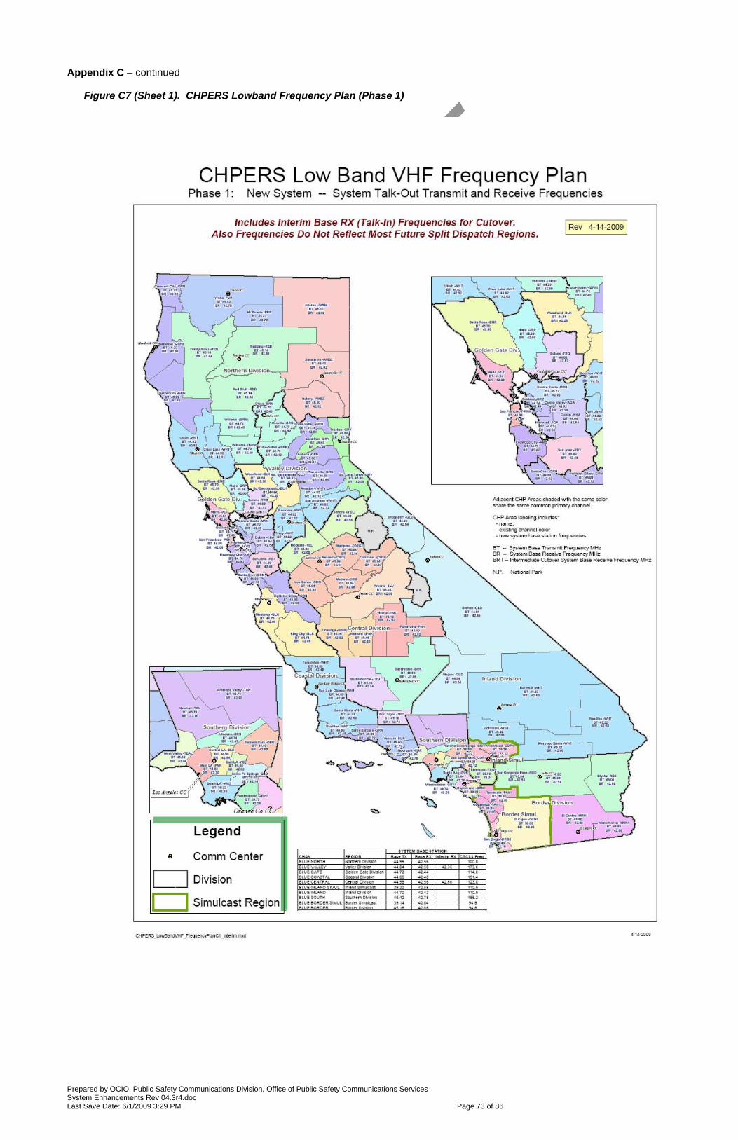
Prepared by OCIO, Public Safety Communications Division, Office of Public Safety Communications Services System Enhancements Rev 04.3r4.doc Last Save Date: 6/1/2009 3:29 PM Page 73 of 86
Appendix C – continued
Figure C7 (Sheet 1). CHPERS Lowband Frequency Plan (Phase 1)

Prepared by OCIO, Public Safety Communications Division, Office of Public Safety Communications Services System Enhancements Rev 04.3r4.doc Last Save Date: 6/1/2009 3:29 PM Page 74 of 86
Appendix C – continued
Figure C7 (Sheet 2). CHPERS Lowband Frequency Plan (Phase 2)

Prepared by OCIO, Public Safety Communications Division, Office of Public Safety Communications Services System Enhancements Rev 04.3r4.doc Last Save Date: 6/1/2009 3:29 PM Page 75 of 86
Appendix C – continued
Figure C7 (Sheet 3). CHPERS Lowband Frequency Plan (Phase 3)

Prepared by OCIO, Public Safety Communications Division, Office of Public Safety Communications Services System Enhancements Rev 04.3r4.doc Last Save Date: 6/1/2009 3:29 PM Page 76 of 86
Exhibits
Exhibit 1. Simple Example of PSCD Work Package (Page 1 of 11)

Prepared by OCIO, Public Safety Communications Division, Office of Public Safety Communications Services System Enhancements Rev 04.3r4.doc Last Save Date: 6/1/2009 3:29 PM Page 77 of 86
Exhibits – continued
Exhibit 1. Simple Example of PSCD Work Package (continued, Page 2 of 11)

Prepared by OCIO, Public Safety Communications Division, Office of Public Safety Communications Services System Enhancements Rev 04.3r4.doc Last Save Date: 6/1/2009 3:29 PM Page 78 of 86
Exhibits – continued
Exhibit 1. Simple Example of PSCD Work Package (continued, Page 3 of 11)

Prepared by OCIO, Public Safety Communications Division, Office of Public Safety Communications Services System Enhancements Rev 04.3r4.doc Last Save Date: 6/1/2009 3:29 PM Page 79 of 86
Exhibits – continued
Exhibit 1. Simple Example of PSCD Work Package (continued, Page 4 of 11)

Prepared by OCIO, Public Safety Communications Division, Office of Public Safety Communications Services System Enhancements Rev 04.3r4.doc Last Save Date: 6/1/2009 3:29 PM Page 80 of 86
Exhibits – continued
Exhibit 1. Simple Example of PSCD Work Package (continued, Page 5 of 11)

Prepared by OCIO, Public Safety Communications Division, Office of Public Safety Communications Services System Enhancements Rev 04.3r4.doc Last Save Date: 6/1/2009 3:29 PM Page 81 of 86
Exhibits – continued
Exhibit 1. Simple Example of PSCD Work Package (continued, Page 6 of 11)

Prepared by OCIO, Public Safety Communications Division, Office of Public Safety Communications Services System Enhancements Rev 04.3r4.doc Last Save Date: 6/1/2009 3:29 PM Page 82 of 86
Exhibits – continued
Exhibit 1. Simple Example of PSCD Work Package (continued, Page 7 of 11)

Prepared by OCIO, Public Safety Communications Division, Office of Public Safety Communications Services System Enhancements Rev 04.3r4.doc Last Save Date: 6/1/2009 3:29 PM Page 83 of 86
Exhibits – continued
Exhibit 1. Simple Example of PSCD Work Package (continued, Page 8 of 11)
Prepared by OCIO, Public Safety Communications Division, Office of Public Safety Communications Services System Enhancements Rev 04.3r4.doc Last Save Date: 6/1/2009 3:29 PM Page 84 of 86
Exhibits – continued
Exhibit 1. Simple Example of PSCD Work Package (continued, Page 9 of 11)

Prepared by OCIO, Public Safety Communications Division, Office of Public Safety Communications Services System Enhancements Rev 04.3r4.doc Last Save Date: 6/1/2009 3:29 PM Page 85 of 86
Exhibits – continued
Exhibit 1. Simple Example of PSCD Work Package (continued, Page 10 of 11)

Prepared by OCIO, Public Safety Communications Division, Office of Public Safety Communications Services System Enhancements Rev 04.3r4.doc Last Save Date: 6/1/2009 3:29 PM Page 86 of 86
Exhibits – continued
Exhibit 1. Simple Example of PSCD Work Package (continued, Page 11 of 11)