system 5cr plus -...
TRANSCRIPT

System 5cr PlusSystem Switcher with Stereo Audio and Projector Control
68-498-01Printed in the USA

This symbol is intended to alert the user of important operating and maintenance(servicing) instructions in the literature provided with the equipment.
This symbol is intended to alert the user of the presence of uninsulated dangerousvoltage within the product's enclosure that may present a risk of electric shock.
CautionRead Instructions • Read and understand all safety and operating instructions before using the
equipment.
Retain Instructions • The safety instructions should be kept for future reference.
Follow Warnings • Follow all warnings and instructions marked on the equipment or in the userinformation.
Avoid Attachments • Do not use tools or attachments that are not recommended by the equipmentmanufacturer because they may be hazardous.
WarningPower sources • This equipment should be operated only from the power source indicated on the
product. This equipment is intended to be used with a main power system with a grounded(neutral) conductor. The third (grounding) pin is a safety feature, do not attempt to bypass ordisable it.
Power disconnection • To remove power from the equipment safely, remove all power cords fromthe rear of the equipment, or the desktop power module (if detachable), or from the powersource receptacle (wall plug).
Power cord protection • Power cords should be routed so that they are not likely to be stepped on orpinched by items placed upon or against them.
Servicing • Refer all servicing to qualified service personnel. There are no user-serviceable partsinside. To prevent the risk of shock, do not attempt to service this equipment yourself becauseopening or removing covers may expose you to dangerous voltage or other hazards.
Slots and openings • If the equipment has slots or holes in the enclosure, these are provided toprevent overheating of sensitive components inside. These openings must never be blocked byother objects.
Lithium battery • There is a danger of explosion if battery is incorrectly replaced. Replace it onlywith the same or equivalent type recommended by the manufacturer. Dispose of used batteriesaccording to the manufacturer's instructions.
Ce symbole sert à avertir l’utilisateur que la documentation fournie avec le matérielcontient des instructions importantes concernant l’exploitation et la maintenance(réparation).
Ce symbole sert à avertir l’utilisateur de la présence dans le boîtier de l’appareil de tensions dangereuses non isolées posant des risques d’électrocution.
AttentionLire les instructions• Prendre connaissance de toutes les consignes de sécurité et d’exploitation avant
d’utiliser le matériel.
Conserver les instructions• Ranger les consignes de sécurité afin de pouvoir les consulter à l’avenir.
Respecter les avertissements • Observer tous les avertissements et consignes marqués sur le matériel ouprésentés dans la documentation utilisateur.
Eviter les pièces de fixation • Ne pas utiliser de pièces de fixation ni d’outils non recommandés par lefabricant du matériel car cela risquerait de poser certains dangers.
AvertissementAlimentations• Ne faire fonctionner ce matériel qu’avec la source d’alimentation indiquée sur
l’appareil. Ce matériel doit être utilisé avec une alimentation principale comportant un fil deterre (neutre). Le troisième contact (de mise à la terre) constitue un dispositif de sécurité :n’essayez pas de la contourner ni de la désactiver.
Déconnexion de l’alimentation• Pour mettre le matériel hors tension sans danger, déconnectez tousles cordons d’alimentation de l’arrière de l’appareil ou du module d’alimentation de bureau (s’ilest amovible) ou encore de la prise secteur.
Protection du cordon d’alimentation • Acheminer les cordons d’alimentation de manière à ce quepersonne ne risque de marcher dessus et à ce qu’ils ne soient pas écrasés ou pincés par desobjets.
Réparation-maintenance • Faire exécuter toutes les interventions de réparation-maintenance par untechnicien qualifié. Aucun des éléments internes ne peut être réparé par l’utilisateur. Afind’éviter tout danger d’électrocution, l’utilisateur ne doit pas essayer de procéder lui-même à cesopérations car l’ouverture ou le retrait des couvercles risquent de l’exposer à de hautes tensionset autres dangers.
Fentes et orifices • Si le boîtier de l’appareil comporte des fentes ou des orifices, ceux-ci servent àempêcher les composants internes sensibles de surchauffer. Ces ouvertures ne doivent jamaisêtre bloquées par des objets.
Lithium Batterie • Il a danger d'explosion s'll y a remplacment incorrect de la batterie. Remplaceruniquement avec une batterie du meme type ou d'un ype equivalent recommande par leconstructeur. Mettre au reut les batteries usagees conformement aux instructions du fabricant.
Safety Instructions • English
Consignes de Sécurité • Français
Sicherheitsanleitungen • Deutsch
Dieses Symbol soll dem Benutzer in der im Lieferumfang enthaltenenDokumentation besonders wichtige Hinweise zur Bedienung und Wartung(Instandhaltung) geben.
Dieses Symbol soll den Benutzer darauf aufmerksam machen, daß im Inneren desGehäuses dieses Produktes gefährliche Spannungen, die nicht isoliert sind unddie einen elektrischen Schock verursachen können, herrschen.
AchtungLesen der Anleitungen • Bevor Sie das Gerät zum ersten Mal verwenden, sollten Sie alle Sicherheits-und
Bedienungsanleitungen genau durchlesen und verstehen.
Aufbewahren der Anleitungen • Die Hinweise zur elektrischen Sicherheit des Produktes sollten Sieaufbewahren, damit Sie im Bedarfsfall darauf zurückgreifen können.
Befolgen der Warnhinweise • Befolgen Sie alle Warnhinweise und Anleitungen auf dem Gerät oder inder Benutzerdokumentation.
Keine Zusatzgeräte • Verwenden Sie keine Werkzeuge oder Zusatzgeräte, die nicht ausdrücklich vomHersteller empfohlen wurden, da diese eine Gefahrenquelle darstellen können.
VorsichtStromquellen • Dieses Gerät sollte nur über die auf dem Produkt angegebene Stromquelle betrieben
werden. Dieses Gerät wurde für eine Verwendung mit einer Hauptstromleitung mit einemgeerdeten (neutralen) Leiter konzipiert. Der dritte Kontakt ist für einen Erdanschluß, und stellteine Sicherheitsfunktion dar. Diese sollte nicht umgangen oder außer Betrieb gesetzt werden.
Stromunterbrechung • Um das Gerät auf sichere Weise vom Netz zu trennen, sollten Sie alleNetzkabel aus der Rückseite des Gerätes, aus der externen Stomversorgung (falls dies möglichist) oder aus der Wandsteckdose ziehen.
Schutz des Netzkabels • Netzkabel sollten stets so verlegt werden, daß sie nicht im Weg liegen undniemand darauf treten kann oder Objekte darauf- oder unmittelbar dagegengestellt werdenkönnen.
Wartung • Alle Wartungsmaßnahmen sollten nur von qualifiziertem Servicepersonal durchgeführtwerden. Die internen Komponenten des Gerätes sind wartungsfrei. Zur Vermeidung eineselektrischen Schocks versuchen Sie in keinem Fall, dieses Gerät selbst öffnen, da beim Entfernender Abdeckungen die Gefahr eines elektrischen Schlags und/oder andere Gefahren bestehen.
Schlitze und Öffnungen • Wenn das Gerät Schlitze oder Löcher im Gehäuse aufweist, dienen diesezur Vermeidung einer Überhitzung der empfindlichen Teile im Inneren. Diese Öffnungen dürfenniemals von anderen Objekten blockiert werden.
Litium-Batterie • Explosionsgefahr, falls die Batterie nicht richtig ersetzt wird. Ersetzen Sieverbrauchte Batterien nur durch den gleichen oder einen vergleichbaren Batterietyp, der auchvom Hersteller empfohlen wird. Entsorgen Sie verbrauchte Batterien bitte gemäß denHerstelleranweisungen.
Este símbolo se utiliza para advertir al usuario sobre instrucciones importantes deoperación y mantenimiento (o cambio de partes) que se desean destacar en elcontenido de la documentación suministrada con los equipos.
Este símbolo se utiliza para advertir al usuario sobre la presencia de elementos convoltaje peligroso sin protección aislante, que puedan encontrarse dentro de la cajao alojamiento del producto, y que puedan representar riesgo de electrocución.
PrecaucionLeer las instrucciones • Leer y analizar todas las instrucciones de operación y seguridad, antes de usar
el equipo.
Conservar las instrucciones • Conservar las instrucciones de seguridad para futura consulta.
Obedecer las advertencias • Todas las advertencias e instrucciones marcadas en el equipo o en ladocumentación del usuario, deben ser obedecidas.
Evitar el uso de accesorios • No usar herramientas o accesorios que no sean especificamenterecomendados por el fabricante, ya que podrian implicar riesgos.
AdvertenciaAlimentación eléctrica • Este equipo debe conectarse únicamente a la fuente/tipo de alimentación
eléctrica indicada en el mismo. La alimentación eléctrica de este equipo debe provenir de unsistema de distribución general con conductor neutro a tierra. La tercera pata (puesta a tierra) esuna medida de seguridad, no puentearia ni eliminaria.
Desconexión de alimentación eléctrica • Para desconectar con seguridad la acometida dealimentación eléctrica al equipo, desenchufar todos los cables de alimentación en el panel traserodel equipo, o desenchufar el módulo de alimentación (si fuera independiente), o desenchufar elcable del receptáculo de la pared.
Protección del cables de alimentación • Los cables de alimentación eléctrica se deben instalar enlugares donde no sean pisados ni apretados por objetos que se puedan apoyar sobre ellos.
Reparaciones/mantenimiento • Solicitar siempre los servicios técnicos de personal calificado. En elinterior no hay partes a las que el usuario deba acceder. Para evitar riesgo de electrocución, nointentar personalmente la reparación/mantenimiento de este equipo, ya que al abrir o extraer lastapas puede quedar expuesto a voltajes peligrosos u otros riesgos.
Ranuras y aberturas • Si el equipo posee ranuras o orificios en su caja/alojamiento, es para evitar elsobrecalientamiento de componentes internos sensibles. Estas aberturas nunca se deben obstruircon otros objetos.
Batería de litio • Existe riesgo de explosión si esta batería se coloca en la posición incorrecta. Cambiaresta batería únicamente con el mismo tipo (o su equivalente) recomendado por el fabricante.Desachar las baterías usadas siguiendo las instrucciones del fabricante.
Instrucciones de seguridad • Español
Precautions

Quick Start — System 5cccccrrrrr Plus
InstallationStep 1Turn off power to the input and output devices,and remove the power cords from them.
Step 2Attach the switcher to the input and output devices.See “Power, video, and audio connections” inchapter 2 for details and diagrams.Input options are:
• RGB for PC 1 and PC 2• RGB, S-video, or composite video for Input 3• S-video or composite video for Vid 1 & Vid 2• Balanced/unbalanced stereo audio for all inputs
Unbalanced Input
TipSleeve
TipSleeve
Balanced Input
TipRing
Sleeve (s)Tip
Ring
TipRing
Sleeve (s)Tip
Ring
Balanced Input(high impedance:
over 10 kohms)(high impedance) (600 ohms)
600 ohms
Output options are:• RGBHV, RGBS, S-video, or composite video
• Balanced or unbalanced audio output via theline level or amplified outputs.
Unbalanced OutputTip
See CautionSleeve (s)
TipSee Caution
Balanced OutputTip
RingSleeve (s)
TipRing
CAUTION Connect sleeve to ground (Gnd).Connecting the sleeve to a negativeterminal will damage the circuits.
Step 3With AC power still removed, connect controldevices and accessories, including an RS-232controller. See “Control device connections” inchapter 2 for details and wiring diagrams.
Step 4Connect power cords and apply power to theswitcher, the input and output devices, and theRS-232 controller.
Step 5Set up (configure) the System 5cr Plus via frontpanel controls, RS-232 SIS commands, or theWindows-based control program.(See the next page.)
VIDMAX.CLIPMIN.
TX RX
IR
LEARNCONFIGRETRYY/C
VID
PC
Y/C
VID
Y/C
ROOMDISPLAY
POWER MUTE MODE PC1 PC2 INPUT 3
VOLUME
AUDIOCOMPUTERAUDIO
PC1 INPUT
PlusSYSTEM 5
VID1 VID2
PC 1 (input 1)RGB computer video input with
audio
IR receiver and IR
learning ports
RGB computer video inputs with audio
IR control LEDs
Audio volume master control or control for
amplified output
Room control
(for Room/ relay port)See pages 2-6 and 4-7.
Display (projector) controls
for setting and sending learned IR commands
(once the button is programmed)
Power LED
S-video or composite video inputs with audio
Front Panel Controls
See “Front Panel Controls and Indicators” in chapter 3 for details. Refer to the Windows-based helpprogram for details on settings.
Audio indicator LEDs (Max, Clip, and Min) — These light in response to changes made via the front panelvolume control knob or RS-232 or control software.Max/Min LEDs (red) – Light when the volume control knob reaches its maximum/minimum limit.
They do not indicate anything about the audio level.Clip LED (green) – Lights when the audio output level starts to peak (overdrive) and the signal is
clipped, often when the input level is too high.
Volume control knob — Adjusts audio volume (audio gain) for the amplified output. It can be used as amaster volume control for both audio outputs if all the inputs have the same level.
IR function LEDs (Tx, Config, Retry) — These indicate stand-alone functions and also are used incombinations during IR learning. See the LED codes table (page 3-7) for details on LED combinations.Transmit (Tx) LED (green) – Lights when the System 5cr Plus transmits infrared signals.Configure (Config) LED (amber) – Lights steadily when the System 5cr Plus is in setup (config.) mode.Retry LED (red) – Lights when the System 5 does not recognize a command during IR learning.

Quick Start — System 5cccccrrrrr Plus, cont’d
50/60 Hz
100-240V 1.3A RS-232R G B
PC 2INPUT 3
VID 1VID 2
H/HV V R G B H/HV VL R
R G/Y
VID
B/C H/HV V
V/Y
V/Y
C
C Y C VID
LiNE OUTL R
L R
L R L
L
R R
L
R
AUX 1 AUX 2 AMPLIFIED OUT
DISPLAY PWRSENSOR
RELAY COMM.
ABCDE
INPUTS
OUTPUTS
Input 3 (configurable)
• RGBHV, RGBS, or RGsB computer video input
or • S-video inputor • composite video input
Room/relay portfor room controls
Input 3
bal./unbal. audio input
PC 2
bal./unbal. audio input
Line level audio output
bal./unbal.
S-video (Y/C)
output
Composite video output
Amplified audiooutput
L/+, R/-
PC 2 (input 2)
RGBHV, RGBS, or RGsB computer video input
RGBHV / RGBSoutput
Vid 2
bal./unbal. audio and• S-video input or
• composite video input
Vid 1
bal./unbal. audio and
• S-video input or• composite video input
Auxiliary outputs
for optional SCP 100P keypads
Communication port
for IR Emitter or IR Broadcaster
RS-232 control port
Power sensor portfor optional display
power sensor
Room Control
To second control pad
SCP 100PControl Panel
Power Sensor
OptionalIR Broadcaster
or
IR Emitter
LCD Projector
SCP 100P
INPUT 3PC2PC1 VID1
MAX.
VOLUME
MIN.
CLIP
VID2
MODEMUTEROOM POWER
Lighting Shades/drapes
IR 401 Remote
System 5cr Plus R
emote
Control Functions
Audio
Input Selection
Display
Power
Display
Mute
Mode
Room
Mute
Volume4
32
15
IR 401
Key to LED Codes
Command has been learned
Continue with setup or exit to normal mode.
Ready to learn the power-off
command
Timeout exit to normal mode
will occur
Press any button to stay in
setup mode.
Try againSetup
mode is active
Configure a
System 5 feature.
Off
On
Off
Blinks once
On
Blinks once
Off
On
Blinks once
Blinks for 5 seconds
Blinks for 5 seconds
Blinks for 5 seconds
Off
On
Blinking
Off
Blinking
Blinking
Off
Blinking
Off
Ready to learn IR
commands
Aim projector's remote at IR learning port.
Press a button for the
function on the remote.
No IR subcarrier
was received
Double-click the System 5's
Display Power button, then press the power button on the projector's
remote.
Press the same System 5 Display button
again,and press the IR remote's
button again.
Press the same button again on the projector's IR remote.
Status
Whatto donext
TXCONFIGRETRY

Press and hold all 3 DISPLAY buttonstogether for 2 seconds.
Press the ROOM button twice.The ROOM LED blinks for 8 seconds.During that time, do one of the following:
Press any desired front panel button to clear & reset only that button's IR configuration.orPress all 3 DISPLAY buttons at the same time for 2 seconds to clear and reset all System 5 settings.
Normal Mode
CONFIG LED lights
Setup(Config)
Mode
With an active audio signal present, press an input's button twice in quick succession to adjust its audio input. The input's LED blinks.
Press the input'sbutton once to save. Repeat foreach audio input.
Turn VOLUME knob up (clockwise)until CLIP LED is on or blinking fast.
Turn VOLUME knob down (counter-clockwise)until the CLIP LED is off or blinks occasionally as the level peaks.
Press and hold the ROOM buttonwhile setting video formats.
Press INPUT3 to toggle betweenvideo formats for that input (an LED
lights to indicate the selected format).
Repeat for VID1 and VID2
Releasethe ROOMbutton
Point the projector's IR remote control at the System 5's IR LEARN port and firmly press the desired button on the remote.
Press theDISPLAY POWER,MUTE, or MODEbutton & hold it for 2 seconds.
CONFIG LED lights steadly while TX & RETRY LEDs flash to indicatethat the signal has been learned.
If the TX LED is off and theRETRY LED blinks once, press thePOWER, MUTE, or MODE button and the IR remote's button again.
For POWER button configuration, if the TX LED is off and both the CONFIG and RETRY LEDs blink, the System 5 is ready to learn the power-off signal.
Press the System 5's POWER button twice in quick succession, then aim the remote and press theIR remote's power button again.
Repeat all steps for eachDISPLAY button to be learned.
CONFIG LED blinks
At any point after entering the setup mode, you can
Configureany of the features described here,
in any order,or
Wait 20 seconds to time out to Normal mode.
Press and hold all 3 DISPLAY buttons together for 2 seconds
to return to Normal Mode.
or
Wait 20 seconds for the System 5 to
time out to Normal Mode.
Settingaudio inputattenuation
levels
InitiatingIR learning
Clearing buttonconfigurations
Selectingvideo formats
TXCONFIGRETRY
ROOMDISPLAY
POWER MUTE MODE
DISPLAYPOWER MUTE MODE
VIDMAX.CLIPMIN.Y/C
VID
PC
Y/C
VID
Y/C
PC1 PC2 INPUT3
VOLUME
AUDIO
VID1 VID2
VID
Y/C
VID
PC
Y/C
VID
Y/C
ROOMDISPLAY
POWER MUTE MODE PC1 PC2 INPUT3 VID1 VID2
TXCONFIGRETRY
TXCONFIGRETRY
orTX
CONFIGRETRY
or
TXCONFIG
RETRY
TX RX LEARNCONFIGRETRY
COMPUTERAUDIOPC1 INPUT IR
PLUSSYSTEM 5
VID
Y/C
VID
PC
Y/C
VID
Y/C
ROOM PC1 PC2 INPUT3 VID1 VID2
1 2 3
4 5 6
7 8
0
9
Setup (Configuration) Procedure

Quick Start — System 5cccccrrrrr Plus, cont’d

iSystem 5cccccrrrrr Plus • Table of Contents
Table of Contents
Chapter 1 • Introduction ....................................................................................................... 1-1
About this Manual ............................................................................................................. 1-2
About the System 5cccccrrrrr Plus ............................................................................................... 1-2What is the System 5cr Plus? .............................................................................................. 1-2Controlling an A/V system ................................................................................................. 1-2
Features and Options ........................................................................................................ 1-4Features .............................................................................................................................. 1-4Options and accessories ..................................................................................................... 1-5
Chapter 2 • Installation .......................................................................................................... 2-1
Mounting the Switcher .................................................................................................... 2-2Table/wall mounting .......................................................................................................... 2-2Rack mounting ................................................................................................................... 2-2
Cabling and Panel Views ................................................................................................. 2-2Power, video, and audio connections ............................................................................... 2-2
Front panel inputs ........................................................................................................ 2-2Rear panel inputs ......................................................................................................... 2-3Outputs ................................................................................................................................ 2-4
Control device connections ............................................................................................... 2-5
Chapter 3 • Setup and Operation .................................................................................... 3-1
Front Panel Controls and Indicators .......................................................................... 3-2
Setting Up the System 5cccccrrrrr Plus ..................................................................................... 3-4Configuring the System 5cr Plus from the front panel ..................................................... 3-4
Clearing configurations ...................................................................................................... 3-4Setting audio input attenuation levels .............................................................................. 3-5Selecting video formats ...................................................................................................... 3-5Initiating IR learning ........................................................................................................... 3-6Key to LED codes ................................................................................................................. 3-7
Remote Control of the System 5cccccrrrrr Plus .................................................................... 3-7
Chapter 4 • Serial Communication ................................................................................. 4-1
RS-232 Programmer’s Guide .......................................................................................... 4-2Host-to-switcher communications .................................................................................... 4-2
Switcher-initiated messages ............................................................................................... 4-2Error responses .................................................................................................................... 4-2Using the command/response tables ................................................................................. 4-3Command/response table for SIS commands .................................................................... 4-4Command/response table for advanced instructions(for the control program for Windows) ............................................................................ 4-5

ii System 5cccccrrrrr Plus • Table of Contents
Table of Contents, cont’d
Control Software for Windows .................................................................................... 4-6Installing the software ...................................................................................................... 4-6Using the software ............................................................................................................ 4-6
Using the control program ................................................................................................. 4-6Saving and restoring configurations ................................................................................. 4-7Using the help program ..................................................................................................... 4-8
Downloading and using projector drivers ........................................................................ 4-8
Appendix A • Appendix ........................................................................................................ A-1
Specifications ....................................................................................................................... A-2
Part Numbers and Accessories .................................................................................... A-4Included parts ................................................................................................................... A-4Accessories ......................................................................................................................... A-4
Firmware Upgrade Installation ................................................................................... A-5
Glossary .................................................................................................................................. A-6
68-498-01 Rev. DPrinted in the USA
02 02

System 5cccccrrrrr Plus
1Chapter One
Introduction
About this Manual
About the System 5cr Plus
Features and Options

Introduction, cont’d
System 5crcrcrcrcr Plus • Introduction1-2
Introduction
About this ManualThis manual discusses how to install, operate and configure the ExtronSystem 5cr Plus switcher and how to operate the IR 401 infrared remote control thatis included with the System 5cr Plus. For information on installing and operatingrelated accessories, see the user’s guides for the following products: Extron’sCurrent/Display Power Sensor (part #68-391-01), IR Broadcaster (part #68-392-02),and SCP 100P Control Pad (part #68-390-01).
Throughout this manual the terms “System 5” and “System 5cr Plus” are usedinterchangeably to refer to the same product.
About the System 5crcrcrcrcr Plus
What is the System 5crcrcrcrcr Plus?The System 5 switcher provides central control for small audio/video (A/V)installations. It offers video and audio switching, room control, and projectorcontrol. Each of these functions can be controlled by the front panel, by a hard-wired control pad (the SCP 100P), and by infrared remote control (the IR 401). Theswitcher can be used to control video and audio input settings; display functionssuch as power, video mute, and video modes; and room functions, such aslowering or raising a display screen or powering lights on or off. The System 5 alsofeatures the ability to “learn” infrared projector control commands.
The System 5 accepts two computer-video (RGB) inputs, two composite video orS-video inputs, and one RGB or composite video or S-video input, for a total of fivevideo inputs. It also accepts five line-level stereo audio inputs.
The System 5 outputs computer video (RGBHV/RGBS/RGsB), or NTSC/PALS-video or composite video to one display device. The System 5 also offers one linelevel (line out) and one amplified stereo audio output. Rear panel ports allowconnection of the IR Emitter and/or the optional IR Broadcaster or hard-wiredprojector remote control, and addition of an optional display power sensor, remotecontrol keypads and an RS-232 controller.
Controlling an A/V systemThe System 5 and other devices can be controlled using one or more of these items:
• The front panel controls.
• A computer, a touch screen panel, or any other device that can send and receiveserial communications through the RS-232 port. Extron’s Simple InstructionSet™ (SIS™) is a set of simple keystroke commands that can be used withany such devices, and Extron’s control software for Windows provides agraphical interface for controlling the switcher from a computer.
• Optional control pads (the SCP 100P) that can be mounted in a wall or podiumand hard-wired to the System 5. Each SCP 100P replicates the front panelfunctions, and it can receive IR signals and pass them to the System 5.
• The IR 401 remote control, which can also perform all of the front panelfunctions.
For the System 5 to control a projector, it must be programmed. The System 5 canprogram itself by learning projector IR commands, or Extron’s IR library ofcommands can be loaded into the System 5’s memory. The IR library and thelatest control software are available on the Extron web site athttp://www.extron.com.
The System 5 learns new projector control commands from infrared (IR) signals itreceives via its front panel IR ports. These commands are added to the panelfunctions. When a function is selected, the System 5 transmits the learned IR signalto the projector through the IR Emitter or the optional IR Broadcaster.

1-3System 5crcrcrcrcr Plus • Introduction
IR commands for the projector can be associated with each of the Display buttons(Power, Mute, and Mode) on the front panel, as well as with each of the five inputbuttons (PC 1, PC 2, Input 3, Vid 1, and Vid 2).
POWER MUTEDISPLAY
SCP 100P
MODE VOLUME
AUDIOROOM
MAX.
CLIP
MIN.
PC1 PC2 INPUT 3 VID1 VID2
IR REMOTE
RGB 406Interface
Front
PlusSystem 5
Rear
SCP 100PControl Pad
To Second Control Pad
VCR
VCR
SVGA Compatible Computeror
Speakers
Powered Speakersor
Cassette RecorderDocument Camera
LCD Projector
Composite
S-video
Audio
IR 401Remote
IR 401 Remote
ComputerInterface
SVGA CompatibleComputer w/ Audio
Laptop Computer
VIDMAX.CLIPMIN.
TX RX
IR
LEARNCONFIGRETRYY/C
Y/C
VID
PC
VID
Y/C
ROOMDISPLAY
POWER MUTE MODE PC1 PC2 INPUT 3
VOLUME
AUDIOCOMPUTERAUDIO
PC1 INPUT
PlusSYSTEM 5
VID1 VID2
50/60 Hz
100-240V 1.3A RS-232R G B
PC 2INPUT 3
VID 1VID 2
H/HV V R G B H/HV VL R
R G/Y
VID
B/C H/HV V
V/Y
V/Y
C
C Y C VID
LINE OUTL R
L R
L R L
L
R R
L
R
AUX 1 AUX 2 AMPLIFIED OUT
DISPLAY PWRSENSOR
RELAY COMM.
INPUTS
OUTPUTS
INPUT HIGH Z
75 Ohm
System 5cr Plus Remote
Control Functions Audio
Input Selection
DisplayPower
DisplayMute
Mode
Room
Mute
Volume
4321
5
IR 401
System 5cr Plus R
emote
Control Functions
Audio
Input Selection
Display
Power
Display
Mute
Mode
Room
Mute
Volume4
32
15
IR 401
A typical System 5crcrcrcrcr Plus application

Introduction, cont’d
System 5crcrcrcrcr Plus • Introduction1-4
Features and OptionsFeatures
250 MHz (-3dB) video bandwidth
Five video inputs —• 2 RGBHV/RGBS/RGsB computer video inputs — A VGA 15-pin HD front
panel connector (PC 1) allows direct connection of a laptop computer, andone set of five BNC rear panel connectors (PC 2) accepts inputs via aninterface.
• 1 RGBHV/RGBS/RGsB computer video or S-video or composite videoinput — A set of five BNC rear panel connectors (Input 3) accepts RGB inputvia an interface, or it can be configured to accept either S-video or compositevideo input instead of RGB input.
• 2 S-video or composite video inputs — Inputs Vid 1 and Vid 2 each havetwo rear-panel BNC connectors.
One video output — A total of eight rear-panel BNC connectors provideconnections for RGB, S-video, or composite video (NTSC/PAL) output. Onlyone output (RGB or S-video or composite video) is active at any one time,even if all three sets of BNCs are connected to the projector.
Five balanced/unbalanced stereo audio inputs — One front panel mini stereo jackand four rear panel captive screw ports accept audio inputs. Each input’slevels can be individually preset, then adjusted by the master volume control.
Two stereo audio outputs —• Line level (line out) output (balanced or unbalanced) via a captive screw
terminal can be treated as a pre-amp. The output can be adjusted using themaster volume control, or it can be set via RS-232 control to provide a fixedoutput level.
• Amplified output (unbalanced) of 24 watts (12 watts per channel with a4 ohm load) or 12 watts ( 6 watts per channel with an 8 ohm load) is availablefor non-powered speakers via spring-loaded captive terminals. The mastervolume control adjusts the output level.
Audio breakaway — Audio and video can be switched separately via RS-232control by using the Windows-based control program.
Three control methods — A computer or other RS-232 control device, the IR 401remote control, or an SCP remote keypad can all be used to control theswitcher.
RS-232 programming — The System 5 can be programmed using an RS-232control device and SIS or Extron’s control software for Windows.
Room control — The System 5 provides a relay for controlling a variety of itemssuch as lighting, window coverings, or display screens.
Projector control — The System 5 can control the projector’s display power, videomute, and mode functions.
IR command learning — The switcher can learn new IR commands from signalsreceived through the front panel or downloaded from Extron’s commandlibrary. Learned commands are output through the IR Emitter or IRBroadcaster.
IR Emitter — The included IR Emitter transmits learned commands and incominginfrared control signals to devices nearby.
Memory — All IR commands are stored in memory.

1-5System 5crcrcrcrcr Plus • Introduction
50/60 Hz
100-240V 1.3A RS-232R G B
PC 2INPUT 3
VID 1VID 2
H/HV V R G B H/HV VL R
R G/Y B/C H/HV V
V/Y
V/Y
C
C Y C VID
LINE OUTL R
L R
L R L
L
R R
L
R
AUX 1 AUX 2 AMPLIFIED OUT
DISPLAY PWRSENSOR
RELAY COMM.
Room Control
Rear
To Second Control Pad
SCP 100PControl Panel
Power Sensor
OptionalIR Broadcaster
or
IR Emitter
LCD Projector RS-232 Control
SCP 100P
INPUT 3PC2PC1 VID1
MAX.
VOLUME
MIN.
CLIP
VID2
MODEMUTEROOM POWER
VID
LIGHTING
SHADES/DRAPES
Front
VIDMAX.CLIPMIN.
TX RX
IR
LEARNCONFIGRETRYY/C
VID
PC
Y/C
VID
Y/C
ROOMDISPLAY
POWER MUTE MODE PC1 PC2 INPUT 3
VOLUME
AUDIOCOMPUTERAUDIO
PC1 INPUT
VID1 VID2
PlusSYSTEM 5
IR 401Remote
IR 401 Remote
System 5cr Plus Remote
Control Functions Audio
Input Selection
DisplayPower
DisplayMute
Mode
Room
Mute
Volume
4321
5
IR 401
System 5cr Plus R
emote
Control Functions
Audio
Input Selection
Display
Power
Display
Mute
Mode
Room
Mute
Volume4
32
15
IR 401
The System 5cr Plus (front and rear) with its options and accessories
Triple-Action Switching™ — With this method, a blank screen is displayed whilethe System 5 switches between RGB inputs.
Versatile mounting options — The System 5 can be rack mounted, or it can bemounted under a desk or table, or on (against) a wall or the side of a desk.Mounting brackets are included.
Options and accessoriesThe System 5’s optional equipment expands a user’s ability to control systemdevices. Optional equipment includes:
• Display power sensor — This sensor (part #60-271-01) detects whether theprojector’s power is on or off in order to keep the System 5 and the projectorin sync.
• Remote control keypad — Up to two hard-wired remote keypads, such asExtron’s SCP 100P control panel (part #60-331-01, -02 or -03) can beconnected via rear panel auxiliary ports. This accessory not only duplicatesthe functions of the System 5’s front panel, it also receives IR signals from theIR 401 and transmits them to the System 5.
• IR broadcast device — A device such as Extron’s IR Broadcaster (part#60-272-01) has a greater range than the IR Emitter and transmits signals overa wide area.

Introduction, cont’d
System 5crcrcrcrcr Plus • Introduction1-6

System 5cccccrrrrr Plus
2Chapter Two
Installation
Mounting the Switcher
Cabling and Panel Views

Installation, cont’d
System 5cccccrrrrr Plus • Installation2-2
TX RX
IR
LEARNCONFIGRETRY
COMPUTERAUDIOPC1 INPUT
PlusSYSTEM 5
Installation
Mounting the SwitcherThe System 5cr Plus comes with two sets of mounting brackets. One set is formounting the switcher under a table or on (against) a wall, and the other set is forrack-mounting.
Table/wall mountingThe table/wall-mounting brackets extend approximately 1/4” (6.3 mm) above thetop surface of the System 5 enclosure, as shown below. This design allows for anair space between the enclosure and the surface on which it is mounted. Attach thetable/wall-mounting brackets to the switcher with the provided machine screws,as shown below.
#8 Screw (4 Plcs)Each Side
Mounting Screws(2 Places)Each Side
or
Rack-mountBracket
Table/Wall-mountBracket
50/60 Hz
100-240V 1.3A
RS-232
R
G
B
PC 2
PC 3
VID 1
VID 2
H/HV
V
R
G
B
H/HV
V
LR
R
G
B
H/HV
V
V/Y
V/Y
C
C
Y
C
VID
PREAMP OUT
LR
LR
LR
L
L
R
R
L
R
AUX 1AUX 2
AMPLIFIED OUT
DISPLAY PWR
SENSOR
RELAYCOMM.
Mounting the System 5crcrcrcrcr Plus
Rack mountingThe switcher can also be rack mounted. Attach the rack-mounting brackets to theswitcher with the provided machine screws, as shown above, then fasten theswitcher to the rack using the supplied machine screws.
Cabling and Panel Views
Power, video, and audio connectionsWith the exception of input PC 1 on the front panel, all input and output connectorsare on the rear panel. The LEDs adjacent to the corresponding buttons on the frontpanel light when each input is active.
Front panel inputsThe PC 1 input on the front panel accepts computer video (RGBHV, RGBS or RGsB)
through a VGA 15-pin HD connector, andunbalanced stereo audio through a 3.5 mm ministereo jack, as shown in the illustration at left.

2-3System 5cccccrrrrr Plus • Installation
To wire the PC 1 audio input plug, follow the wiring diagram shown below.Tip (+) Sleeve (GND)
Tip (L, +)
Ring (R, -)
Sleeve (GND)
PC1 audio input plug wiring
Rear panel inputs
1 AC power connector — Plug a standard IEC power cord into this port toconnect the switcher to a 100 to 240VAC, 50 Hz or 60 Hz power source.
2 PC 2 and Input 3 computer video inputs — These inputs accept VGA-typecomputer-video signals, and each has 5 female BNC connectors for RGB videoinput with composite or separate horizontal and vertical sync. Input 3 can beconfigured for RGB or S-video or composite video.
For PC 2:R G B H/HV VR G B H/HV V
RGBS
R G B H/HV V
RGBHV RGsB (Sync on Green)
For Input 3:R B/C H/HV VR B/C H/HV V
RGBS
R G/Y
VID
G/Y
VID
G/Y
VID
G/Y
VID
G/Y
VID
B/C H/HV V
RGBHV RGsB (Sync on Green)
R B/C H/HV V
S-video (Y/C)
R B/C H/HV V
Composite Video
For S-video, connect the luma (Y) signal to the BNC connector marked G/Yand Vid, and the chroma signal (C) to the BNC marked B/C, as shown above.
Configure the video format via the front panel (see page 3-5) or using RS-232programming (see chapter 4, “Serial Communication”).
3 PC 2, Input 3, Vid 1, and Vid 2 audio inputs — Each input has a 3.5 mm,5-pole captive screw connector for balanced or unbalancedstereo audio input. Connectors are included with each System 5,but the user supplies the audio cable. See the wiring diagramsbelow to wire a connector for the appropriate input type andimpedance level. High impedance is generally over 800 ohms.
Unbalanced Input
TipSleeve
TipSleeve
Balanced Input
TipRing
Sleeve (s)Tip
Ring
TipRing
Sleeve (s)Tip
Ring
Balanced Input(high impedance) (high impedance) (600 ohms)
600 ohms
600 ohms
Captive screw connector wiring for rear panel audio inputs
50/60 Hz
100-240V 1.3A R G B
PC 2INPUT 3
VID 1VID 2
H/HV V L R
R G/Y
VID
B/C H/HV V
V/Y
V/Y
C
CL R
L R
L R
INPUTS
1 3 342

Installation, cont’d
System 5cccccrrrrr Plus • Installation2-4
RS-232R G B H/HV V
Y C VID
LINE OUTL
L
R R
L
R
AUX 1 AUX 2 AMPLIFIED OUT
DISPLAY PWRSENSOR
RELAY COMM.
ABCDE
OUTPUTS
3
1
2 54
4 Vid 1 and Vid 2 composite/S-video inputs — Connect the cables as shownhere. For S-video, connect the luma (Y) signal tothe left BNC connector, marked V/Y, and thechroma signal (C) to the right BNC, marked C.
Configure the video format via the front panel or using RS-232 programming.
Outputs
All three outputs can be connected simultaneously, although only one is activeat a time. The output that is active is determined by the format of the activeinput.
The LED next to the connector(s) for each output (RGB, S-video, or compositevideo) lights when that output is active.
1 RGB output BNC connectors — Connect coaxial cables from the displaydevice to these BNCs for one RGBHV or RGBS video output as follows:
R G B H/HV V
RGBS
R G B H/HV V
RGBHV
2 S-video output (Y, C) — For S-video output, connect the cable for the luma (Y)signal to the Y connector, and the cable for chroma (C) signal to the Cconnector. A BNC-to-4-pin mini DIN (S-video) adapter may be required.
3 Composite video output BNC (Vid) — Connect the display device here, via acoaxial cable, for composite video output.
4 Line level audio output (Line Out) — For unamplified, line level audiooutput, connect an audio device, such as an audio recorder or poweredspeakers, to this 3.5 mm, 5-pole captive screw connector. Follow the wiringdiagram below.
Unbalanced OutputTip
See CautionSleeve (s)
TipSee Caution
Balanced OutputTip
RingSleeve (s)
TipRing
CAUTION Connect the sleeve to ground (Gnd). Connecting the sleeve to a negative(-) terminal will damage the audio output circuits.
The signal at this output comes from the selected audio input. The audio levelfrom the Line Out output can either be variable (in response to front panelvolume adjustment), or it can be set to a fixed level that is not affected bychanges to the front panel volume adjustment. Use the Windows-basedcontrol program to change the output mode setting or to set audio breakaway.See chapter 4, Serial Communication, for details.
5 Amplified audio output — Connect unpowered speakers directly to thesespring-loaded captive terminals for stereo output. Connect the left channelsto positive/L, and the right channels to negative/R.
V/Y C V/Y C
S-video Composite video

2-5System 5cccccrrrrr Plus • Installation
This output provides 24 watts of power (12 watts per channel with a 4 ohmload) or 12 watts ( 6 watts per channel with an 8 ohm load). The output levelvaries depending on the front panel volume adjustment.
Control device connectionsCaptive screw and 3.5 mm stereo jack connectors are included with theSystem 5, but the installer provides the cables.
RS-232
L
R
L
R
AUX 1 AUX 2 AMPLIFIED OUT
DISPLAY PWRSENSOR
RELAY COMM.
ABCDE
2 431 5
1 Auxiliary outputs (Aux 1, Aux 2) — One optional external SCP 100P,SCP 250, or SCP/AAP A control panel can be connected to each of these5-pole captive screw connectors. The control panel replicates the switcher’sfront panel control features. Wire the connectors as shown below.
IR signals in (violet)Gnd (black)
Gnd (drain)+12V (red)
System 5AUX port
AUX
ABCDE
ABCDE
Comm signal (white)
IR signals in (violet)Gnd (black)
Gnd (drain)+12V (red)
Comm signal (white)
Port onSCP
circuitboard
The Aux 1 and Aux 2 ports provide a total of 500 mA, split between the twoports, so each port provides 250 mA of current. Refer to the SCP 100P User’sManual (part #68-390-01) or the SCP/AAP A, SCP 200, SCP 250 User’s Manual(part #68-511-01) for details about the control panels.
2 Room/relay port (Relay) — This allows control of “room” functions – itemssuch as room lighting, window coverings, and display screens – viamomentary or latching contact. These contacts can be used to control anyequipment as long as the contact specifications of a total of 24 volts at1 ampere are not exceeded.
This port has two sets of contacts: one pair is closed by default, the other pairis open by default, as shown below.
Normally closed (2)
Normally closed (1)
Normally open (2)
Normally open (1) Notused
Sys
tem
5R
EL
AY
po
rt
To / fromroom controlequipment
Normally closed (2)Normally closed (1)Normally open (2)Normally open (1)Not used
When the room function is active, the closed contacts open, and the opencontacts close. Contacts can be programmed to operate in one of two ways:• latching (brief contact) (press to turn on, press to turn off), or• momentary (timed) (press to turn on, timeout to turn off).
In the timed mode the default timeout period is 1/8 second. Use the controlsoftware for Windows to change the length of the timeout period. See SerialCommunications, chapter 4, for details.
Installation, cont’d
System 5cccccrrrrr Plus • Installation2-6
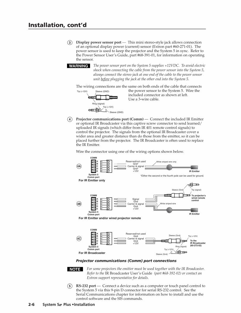
3 Display power sensor port — This mini stereo-style jack allows connectionof an optional display power (current) sensor (Extron part #60-271-01). Thepower sensor is used to keep the projector and the System 5 in sync. Refer tothe Power Sensor User’s Guide, part #68-391-01, for information on operatingthe sensor.
The power sensor port on the System 5 supplies +12VDC. To avoid electricshock when connecting the cable from the power sensor into the System 5,always connect the stereo jack at one end of the cable to the power sensorunit before plugging the jack at the other end into the System 5.
The wiring connections are the same on both ends of the cable that connectsthe power sensor to the System 5. Wire theincluded connector as shown at left.Use a 3-wire cable.
4 Projector communications port (Comm) — Connect the included IR Emitteror optional IR Broadcaster via this captive screw connector to send learned/uploaded IR signals (which differ from IR 401 remote control signals) tocontrol the projector. The signals from the optional IR Broadcaster cover awider area and greater distance than do those from the emitter, so it can beplaced further from the projector. The IR Broadcaster is often used to replacethe IR Emitter.
Wire the connector using one of the wiring options shown below.
Reserved/not usedGnd*
Carrier & signalGnd*+12V
System 5Comm port
System 5Comm port
For IR Emitter only
For IR Emitter and/or wired projector remote
COMM
IR Emitter
*Either the second or the fourth pole can be used for ground.
4A
ABCDE
White striped wire only
SignalGnd
Carrier & signalGnd+12V
COMM
IR Emitter
To projector'swired remotecontrol
Tip (signal)Sleeve (Gnd)
4B
ABCDE
White striped wire
System 5Comm port
For IR Broadcaster
Reserved/not usedGnd
Carrier & signalGnd+12V
COMM
Tip (+12V)Sleeve (Gnd)
Tip (+12V)
Ring (signal)
Sleeve (Gnd)
To theIR Broadcaster(60-272-02)
4C
ABCDE
Projector communications (Comm) port connections
For some projectors the emitter must be used together with the IR Broadcaster.Refer to the IR Broadcaster User’s Guide (part #68-392-02) or contact anExtron support representative for details.
5 RS-232 port — Connect a device such as a computer or touch panel control tothe System 5 via this 9-pin D connector for serial RS-232 control. See theSerial Communications chapter for information on how to install and use thecontrol software and the SIS commands.
Tip (+12V) Sleeve (GND)
Tip (+12V)
Ring (signal)
Sleeve (GND)

System 5cccccrrrrr Plus
3Chapter Three
Operation
Front Panel Controls and Indicators
Setting Up the System 5cr Plus
Remote Control of the System 5cr Plus

Setup and Operation, cont’d
System 5cccccrrrrr Plus • Setup and Operation3-2
Setup and Operation
Front Panel Controls and Indicators
VIDMAX.CLIPMIN.
TX RX
IR
LEARNCONFIGRETRYY/C
VID
PC
Y/C
VID
Y/C
ROOMDISPLAY
POWER MUTE MODE PC1 PC2 INPUT 3
VOLUME
AUDIOCOMPUTERAUDIO
PC1 INPUT
PlusSYSTEM 5
VID1 VID2
1 4 5 9 10 112 6 83 7
Most of the front panel controls described in this section also have another functionduring setup. See Setting Up the System 5cr Plus in this chapter.
The SCP 100P remote keypad and the Windows-based control software replicateitems 2 through 10 shown above, which are described in this chapter. TheIR 401 remote control replicates the controls without the LEDs.
When the System 5 powers up, all of the front panel LEDs light briefly, thenturn off. The Power LED (1) lights and stays on until the System 5 is powereddown. The LED for the last selected input, and the rear panel LED for theselected input format will light and remain on until the input is changed.
1 Power LED — This lights to indicate that the System 5 is receiving power.
2 Room button and LED — This allows control of “room” functions – itemssuch as room lighting, window coverings, and display screens – viamomentary or latching contact through the Relay port. These contacts can beused to control any equipment as long as the contact specifications of a totalof 24 volts at 1 ampere are not exceeded. The LED lights while the roomfunction is active (on). See page 2-5 for information on the room/relay port,and see page 4-7 and refer to the Windows-based System 5cr Help programfor details on changing settings.
Display function controls and LEDsThe settings of the display functions (power, mute, and mode) are customized foreach projector. These buttons function only after they have been programmed,either by “learning” IR commands or by loading projector commands (drivers)from the Extron IR library.
3 Display power (Power) button and LED — Once the System 5 has beenprogrammed with the commands for the specific projector, pressing thisbutton toggles the projector’s power on or off.
The LED lights when projector power is on. The LED blinks quickly duringprojector power-up, and it blinks slowly during projector power-down.While the LED is blinking, do not send commands to the projector becausethe projector is not able to accept them. The blinking periods (power-up/down delay time) are generated within the System 5, not the projector. Theblinking periods can be set only via the Windows-based control program.
4 Display mute (Mute) button — Press this button to toggle the projector’s“mute” function (to turn off/on the displayed image) once the Mute buttonhas been programmed for use with the projector.
5 Display mode (Mode) button — This button can be programmed to switchthe mode of the projector between computer-video (RGB), S-video, andcomposite video. It replicates the 1-button (step) mode function provided onsome projectors’ remote controls.
Input selection controls and LEDsUse these buttons to select the appropriate input source. LEDs next to each buttonindicate the format of the incoming video signal. Only the selected input’s LED

3-3System 5cccccrrrrr Plus • Setup and Operation
lights. If the System 5 has learned commands, it may send IR commands (such as adisplay mode change command) to the projector when an input is selected.
6 PC 1 and PC 2 — Press these buttons to select input 1 (PC 1, front panel) orinput 2 (PC 2, rear panel), respectively. Both inputs accept only RGBcomputer-video and audio.
7 Input 3 — This button corresponds to Input 3 (rear panel), which can beconfigured to accept audio and RGB, or S-video, or composite video. TheLED corresponding to the selected format lights when Input 3 is selected.
8 Vid 1 and Vid 2 — Press these buttons to select input 4 (Vid 1) or input 5 (Vid 2),respectively. Both of these rear panel inputs can be configured to accept audioand either S-video or composite video.
Audio breakaway (the ability to separately switch audio and video signals fromdifferent inputs) is available only via the RS-232 control. While audiobreakaway is active, the flashing LED indicates the input providing the audiosignal, and the steadily lit LED indicates the active video input.
Audio adjustment control and LEDs
9 Audio indicator LEDs (Max, Clip, and Min) — These LEDs light in responseto changes made via the front panel volume control knob or RS-232 or controlsoftware commands.
Max LED (red) – This LED lights when the volume control knob has reachedits maximum limit. It does not indicate anything about the audio level.
Clip LED (green) – This LED lights when the audio output level starts to peak(overdrive) and the signal is clipped, often when the input level is toohigh. It is used mostly during audio input attenuation setup.
Min LED (red) – This LED lights when the volume control knob has reachedits minimum limit. It does not indicate the audio level.
10 Volume control knob — Turn this to adjust the audio volume (audio gain) forthe amplified output. The volume control knob can be used as a mastervolume control for both audio outputs if all the audio inputs have the samelevel. There is no physical limit to this knob’s rotation. The Min or Max LEDwill light briefly when the knob has reached its functional minimum ormaximum limit.
Audio gain/attenuation can be set per input via the front panel controls or viaRS-232 commands or the Windows-based control program. For details, seeSetting Up the System 5cr Plus in this chapter, and chapter 4, SerialCommunication.
Infrared control LEDs
11 IR function LEDs (Tx, Config, Retry) — These three LEDs indicate stand-alone functions and also are used in combinations during IR learning. Forexample, all three LEDs flash at once to indicate a timeout when the System 5is in configuration mode. See Setting Up the System 5cr Plus in this chapter fordetails on when the LEDs light in combination.
Transmit (Tx) LED (green) – This lights while the System 5 transmits infraredsignals.
Configure (Config) LED (amber) – This lights steadily when theSystem 5 is in setup (configuration) mode.
Retry LED (red) – This lights when the System 5 does not recognize acommand during the infrared learning process.

Setup and Operation, cont’d
System 5cccccrrrrr Plus • Setup and Operation3-4
Setting Up the System 5cccccrrrrr PlusThe System 5cr Plus must be set up (configured) before it can control otherequipment. Setup can be done from the front panel, or from a computer using theprovided control software. Setup cannot be done via the IR 401 remote control orthe SCP 100P control pad.
Extron provides preset configurations in the form of projector driver files that canbe downloaded from diskette or the Extron website. See “Downloading and usingprojector drivers” in chapter 4 for details. Projector drivers assign projector IRcommands to the System 5’s front panel controls so that the display power, mute,and mode functions can be used to control the projector.
Configuring the System 5cccccrrrrr Plus from the front panelThe System 5 must be in the setup (config) mode during setup. The Config LEDlights when the setup mode is on. The following configuration procedures can beperformed from within setup mode:
• clear an individual button’s IR function configurations,• clear all System 5 settings,• set audio input attenuation levels,• select video formats,• initiate IR learning.
See the flowcharts in this section for the specific steps for setting up the System 5.
When there has been no activity for at least 20 seconds, the System 5 times outfrom the setup mode to the normal mode, and the Tx, Config, and Retry LEDswill all flash for 5 seconds.
Clearing configurationsClearing configuration settings resets them to factory defaults. To clearconfigurations, see the flowchart below.
Press and hold all 3 DISPLAY buttonstogether for 2 seconds.
Normal Mode
CONFIG LED lights
Setup(Config)
Mode
At any point after entering the Setup mode, you can
Configure any feature in any order,or
Wait 20 seconds to time out to Normal mode.
Press and hold all 3 DISPLAY buttons together for 2 seconds
to return to Normal Mode.
or
Wait 20 seconds for the System 5 to
time out to Normal Mode.
Press the ROOM button twice.The ROOM LED blinks for 8 seconds.During that time, do one of the following:
Press any desired front panel button to clear & reset only that button's IR configuration.orPress all 3 DISPLAY buttons at the same time for 2 seconds to clear and reset all System 5 settings.
TXCONFIGRETRY
ROOMDISPLAY
POWER MUTE MODE
DISPLAYPOWER MUTE MODE
VID
Y/C
VID
PC
Y/C
VID
Y/C
ROOM PC1 PC2 INPUT3 VID1 VID2
Pressing all three Display buttons clears and resets all configuration settingsto the factory defaults. These settings include Display functions, IR commands,room settings, video type, RGB delay, power up/down delay, room relay mode,audio gain, and all other settings.

3-5System 5cccccrrrrr Plus • Setup and Operation
Setting audio input attenuation levelsBefore setting the audio levels, ensure that all the audio input sources are activeand connected to the System 5. To set the audio levels, see the following flowchart.
Press and hold all 3 DISPLAY buttonstogether for 2 seconds.
CONFIG LED lights
Setup(Config)
Mode
At any point after entering the Setup mode, you can
Configure any feature in any order,or
Wait 20 seconds to time out to Normal mode.
Press and hold all 3 DISPLAY buttons together for 2 seconds
to return to Normal Mode.
or
Wait 20 seconds for the System 5 to
time out to Normal Mode.
With an active audio signal present, press an input's button twice in quick succession to adjust its audio input. The input's LED blinks.
Press the input's button once to save.Repeat for each audio input.
Turn VOLUME knob up (clockwise)until CLIP LED is on or blinking fast.
Turn the VOLUME knob down(counter-clockwise) until
the CLIP LED is off or blinksoccasionally as the level peaks.
TXCONFIGRETRY
ROOMDISPLAY
POWER MUTE MODE
VIDMAX.CLIPMIN.Y/C
VID
PC
Y/C
VID
Y/C
PC1 PC2 INPUT3
VOLUME
AUDIO
VID1 VID2
Selecting video formatsInput 3 can be set to accept computer-video (RGB), S-video (Y/C), or compositevideo (Vid, V). Vid 1 (input 4) and Vid 2 (input 5) can be set for S-video orcomposite video. Select the format as shown below.
Press and hold all 3 DISPLAY buttonstogether for 2 seconds.
Normal Mode
CONFIG LED lights
Setup(Config)
Mode
At any point after entering the Setup mode, you can
Configure any feature in any order,or
Wait 20 seconds to time out to Normal mode.
Press and hold all 3 DISPLAY
buttons togetherfor 2 seconds
to return toNormal Mode.
or
Wait 20 seconds for the System 5
to time out to Normal Mode.
Press and hold the ROOM buttonwhile setting video formats.
Press INPUT3 to toggle betweenvideo formats for that input (an LED
lights to indicate the selected format).
Repeat for VID1 and VID2
Releasethe ROOM
button
TXCONFIGRETRY
ROOMDISPLAY
POWER MUTE MODE
VID
Y/C
VID
PC
Y/C
VID
Y/C
ROOMDISPLAY
POWER MUTE MODE PC1 PC2 INPUT3 VID1 VID2

Setup and Operation, cont’d
System 5cccccrrrrr Plus • Setup and Operation3-6
Initiating IR learningThe System 5 can “learn” control commands from projectors’ remote controls.IR learning is only necessary if there is no IR driver available for that projector or ifthe driver is not complete.
The System 5cr Plus has two portholes on its front panel:
TX RX
IR
LEARNCONFIGRETRY
PlusSYSTEM 5• one for the IR receiver (Rx), which receives signals
from the IR 401 remote; and
• one for the IR learning device (Learn), which receivessignals from a projector’s remote control duringIR learning.
During IR learning you might need to hold the projector’s IR remote control as nearto the System 5 as one-half inch and point the remote directly at the IR learning(Learn) device. Blocking ambient light from the IR learning device, particularlyfrom flourescent lights, can also help.
Once the System 5 has been programmed to control the projector, do notperform the learned projector control functions from the projector or theprojector’s remote control. The System 5 will not know that projector controlcommands have been sent by an external device. For example, if a projector ispowered on via the System 5, and then the projector is manually turned off atthe projector’s panel, the System 5 will not know the projector is off, and it willcontinue to send video signals and commands to the projector.
Press and hold all 3 DISPLAY buttonstogether for 2 seconds.
Normal Mode
CONFIG LED lights
Setup(Config)
Mode
At any point after entering the Setup mode, you can
Configure any feature in any order,or
Wait 20 seconds to time out to Normal mode.
Press and hold all 3 DISPLAY buttons together for 2 seconds
to return to Normal Mode.
or
Wait 20 seconds for the System 5 to
time out to Normal Mode.
Point the projector's IR remote control at the System 5's IR LEARN port and firmly press the desired button on the remote.
Press theDISPLAY POWER,MUTE, or MODEbutton & hold it for 2 seconds.
CONFIG LED lights steadlywhile TX & RETRY LEDs flash toindicate that the signal was learned.
If the TX LED is off and theRETRY LED blinks once, retry by pressing the POWER, MUTE, or MODE button and the IR remote's button again.
For POWER button configuration, if the TX LED is off and the CONFIG and RETRY LEDs both blink, the System 5 is ready to learn the power-off signal.
Press the System 5's POWER button twice in quick succession, then aim the remote and press theIR remote's power button again.
Repeat all steps for eachDISPLAY button to be learned.
CONFIG LED blinks
TXCONFIGRETRY
ROOMDISPLAY
POWER MUTE MODE
TXCONFIGRETRY
TXCONFIGRETRY
orTX
CONFIGRETRY
or
TXCONFIG
RETRY
TX RX LEARNCONFIGRETRY
COMPUTERAUDIOPC1 INPUT IR
PLUSSYSTEM 5
1 2 3
4 5 6
7 8
0
9

3-7System 5cccccrrrrr Plus • Setup and Operation
Remote Control of the System 5cccccrrrrr PlusThe System 5 can be controlled by using its front panel controls, the includedIR 401 infrared remote control, optional SCP remote control panels, or anRS-232 control device or computer.
The IR 401 and SCP control panels replicate the System 5’s front panel controls fornormal mode operations. The RS-232 control device also can send front panelnormal mode commands. A computer using Extron’s Windows-based controlprogram can perform both normal mode and setup mode operations, and it offerssome functions that are not available with the other control methods. See chapter 4,Serial Communication, for details.
The IR 401 uses and buttons inplace of the volume knob. It also hasan audio mute button.
Setup mode operations can not beperformed from the IR 401.
Control Functions Audio
Input Selection
DisplayPower
DisplayMute
Mode
Room
Mute
Volume
4321
5System 5cr Plus Remote
Control Functions Audio
Input Selection
DisplayPower
DisplayMute
Mode
Room
Mute
Volume
4321
5
IR 401
To interpret the System 5’s response to the IR learning steps, see the LED responsecodes below.
Key to LED Codes
Command has been learned
Continue with setup or exit to normal mode.
Ready to learn the power-off
command
Timeout exit to normal mode
will occur
Press any button to stay in
setup mode.
Try againSetup
mode is active
Configure a
System 5 feature.
Off
On
Off
Blinks once
On
Blinks once
Off
On
Blinks once
Blinks for 5 seconds
Blinks for 5 seconds
Blinks for 5 seconds
Off
On
Blinking
Off
Blinking
Blinking
Off
Blinking
Off
Ready to learn IR
commands
Aim projector's remote at IR learning port.
Press a button for the
function on the remote.
No IR subcarrier
was received
Double-click the System 5's
Display Power button, then press the power button on the projector's
remote.
Press the same System 5 Display button
again,and press the IR remote's
button again.
Press the same button again on the projector's IR remote.
Status
Whatto donext
TXCONFIGRETRY
The SCP 100P, SCP/AAP A, and SCP 250 can be mounted in a wall or furniture.Each includes an IR remote window (corresponding to the IR receiver port on the
System 5) or IR signal pickup device for receivingcommands from the IR 401 remote control and sendingthem to the System 5. Infrared signals from otherdevices are not passed on to the IR Emitter or the IRBroadcaster. Up to two SCPs can be connected to theSystem 5.
SHOW MEMAX/MIN
AUDIOVOLUME
POWER MUTEDISPLAY
MODE
SCP/ AAP A

Setup and Operation, cont’d
System 5cccccrrrrr Plus • Setup and Operation3-8
SCP 100P
PC1
ROOM POWER MUTE MODE
IR REMOTE
VOLUME
MAX.
MIN.
CLIP
PC2 INPUT 3 VID1 VID2
DISPLAY AUDIO
Setup mode operations can not be performed from the SCP control panel(s).
Refer to the SCP 100P User’s Manual(part #68-390-01) or the SCP/AAP A, SCP 200,SCP 250 User’s Manual (part #68-511-01) fordetails about the control panels.
SCP 250
IR
DISPLAY AUDIO
VOLUME
POWER MUTE MODE MAX/
MIN
ROOM 1 2 3 4 5
The SCP 250 can also be used with theExtron System 7SC switcher. When theSCP 250 is used with the System 5crPlus, the last three buttons are not used.

System 5cccccrrrrr Plus
4Chapter Four
Serial Communication
RS-232 Programmer’s Guide
Control Software for Windows

Serial Communication, cont’d
System 5cccccrrrrr Plus • Serial Communication4-2
Serial Communication
The System 5cr Plus can be remotely controlled via a host computer or other device(such as a control system) attached to the rear panel RS-232 connector. The controldevice (host) can use either Extron’s Simple Instruction Set (SIS) commands or thegraphical control program for Windows.
The System 5 switcher uses a protocol of 9600 baud, 1 stop bit, no parity, andno flow control.
The rear panel RS-232 9-pin D connector has the following pin assignments:
Pin RS-232 function Description
2 Tx Transmit data3 Rx Receive data5 Gnd Signal ground
DB9 Pin LocationsFemale
5
1
9
6
RS-232 Programmer’s Guide
Host-to-switcher communicationsSIS commands consist of one or more characters per field. No special charactersare required to begin or end a command sequence. When the System 5cr Plusdetermines that a command is valid, it executes the command and sends aresponse to the host device. All responses from the switcher to the host end with acarriage return and a line feed (CR/LF = ), which signals the end of the responsecharacter string. A string is one or more characters.
Switcher-initiated messagesWhen a local event such as a front panel (or SCP control pad) selection oradjustment takes place, the System 5 switcher responds by sending a message tothe host. No response is required from the host. The switcher-initiated messagesare listed here (underlined).
(C) Copyright 2000, Extron Electronics, System 5cr Plus, Vx.xx The System 5 sends the copyright message when it first powers on. Vx.xx is thefirmware version number.
RECONFIG When a change is made via a front panel control or another operation occurs thatmust be written to a new memory block, the System 5 sends the reconfigurationmessage. No response is required from the RS-232 host, but the host may request anew status listing via the request information command (I/i). See the command/response table in this chapter for details.
C X1 (where X1 is the input number)The System 5 sends this response when an input is switched. C = both audio andvideo were switched.
Error responsesWhen the switcher receives a valid SIS command, it executes the command andsends a response to the host device. If the System 5 is unable to execute thecommand because the command is invalid or it contains invalid parameters, itreturns an error response to the host.

4-3System 5cccccrrrrr Plus • Serial Communication
The error response codes and their descriptions are as follows:
E01 – Invalid input channel number (the number is too large)E10 – Invalid commandE13 – Invalid value (the number is out of range/too large)E16 – Unit is busyE23 – Checksum error.
Using the command/response tablesThe command/response tables on the next page list valid command ASCII codes,the switcher’s responses to the host, and a description of the command’s functionor the results of executing the command. Lower case characters are acceptable inthe command field only where indicated.
The ASCII to HEXconversion table at left isfor use with thecommand/response tables.
ASCII to HEX Conversion Table
•
ASCII to Hex conversion table
Serial Communication, cont’d
System 5cccccrrrrr Plus • Serial Communication4-4
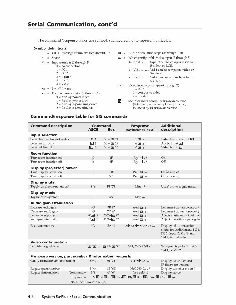
Command/response table for SIS commands
Command description Command Response AdditionalASCII Hex (switcher to host) description
Input selectionSelect both video and audio X1 ! 30 + X1 21 C X1 Video & audio input X1 .Select audio only X1 $ 30 + X1 24 A X1 Audio input X1 .Select video only X1 & 30 + X1 26 V X1 Video input X1 .
Room functionTurn room function on O 4F Rly X2 On.Turn room function off o 6F Rly X2 Off.
Display (projector) powerTurn display power on [ 5B Pwr X3 On (discrete).Turn display power off ] 5D Pwr X3 Off (discrete).
Display muteToggle display mute on/off S/s 53/73 Mut Use S or s to toggle mute.
Display modeToggle display mode J 4A Mde
Audio gain/attenuationIncrease audio gain {G 7B 47 Aud X4 Increment up (amp output).Decrease audio gain }G 7D 47 Aud X4 Increment down (amp out.).Set amp output gain 0* X4 G 30 2A X4 47 Aud X4 Affects master output volume.Set input attenuation 1* X4 G 31 2A X4 47 Aud X4 Adjusts the active input’s gain.
Read attenuators *A 2A 41 X4 • X4 • X4 • X4 • X4 Displays the attenuationstatus for audio inputs PC 1,
PC 2, Input 3, Vid 1, andVid 2, in that order.
Video configurationSet video signal type X5 * X6 \ X5 2A X6 5C Vid/Y-C/RGB Set signal type for Input 3,
Vid 1, or Vid 2.
Firmware version, part number, & information requestsQuery firmware version number Q/q 51/71 Ver X7 • X7 Display controller and
IR firmware version.Request part number N/n 4E/6E N60-269-02 Display switcher’s part #.Request information Command = I/i 49/69 (see below) Display status.
Response = V X1•A X1•T X6 •Pwr X3 •Rly X2 •Clp X2 • Amt X2 •Aud X4
Note: Amt is audio mute.
The command/response tables use symbols (defined below) to represent variables.
X4 = Audio attenuation steps (0 through 100)
X5 = Which configurable video input (3 through 5)3= Input 3 ....... Input 3 can be composite video,
S-video, or RGB.4 = Vid 1 .......... Vid 1 can be composite video or
S-video.5 = Vid 2 .......... Vid 2 can be composite video or
S-video.X6 = Video input signal type (0 through 2)
0 = RGB1 = composite video2 = S-video
X7 = Switcher main controller firmware version(listed to two decimal places e.g.: x.xx),followed by IR firmware version
Symbol definitions= CR/LF (carriage return/line feed) (hex 0D 0A)
• = SpaceX1 = Input number (0 through 5)
0 = no connection1 = PC 12 = PC 23 = Input 34 = Vid 15 = Vid 2
X2 = 0 = off, 1 = on
X3 = Display power status (0 through 3)0 = display power is off1 = display power is on2 = display is powering down3 = display is powering up

4-5System 5cccccrrrrr Plus • Serial Communication
Flag blockThe flag block consists of fifteen bytes (0 to 14) that will be used for handlingspecial operation functions.
Byte 0 – Power on delayByte 1 – Power off delayByte 2 – Triple-action switching delay (0.5 second * value)Byte 3 – Relay controlByte 4 – Not usedByte 5 – Not usedByte 6 – Not usedByte 7 – Mute control and various flags
Bit 7 – true = mute audio upon display power-downBit 6 – true = limit initial system volume (upon switcher power-up)Bit 5 – true = send responses to RS-232 commandsBit 4 – true = send channel change IR command upon display power-upBit 3 – false = disable front panel volume knobBit 2 – false = disable IR while display power is offBit 1 – false = fixed Line Out output level (1 = volume knob controls Line Out)Bit 0 – unused
The factory default for byte 7 is all bits set to On (hex FF).
Byte 8 – Video type (composite video, S-video, or RGB)Bit 5 = video 5 mode
0 = video1 = S-video
Bit 4 = video 4 mode0 = video1 = S-video
Bit 3 = reservedBits 2 & 1 = video 3 mode
00 = RGB01 = S-video10 = video11 = undefined
Bit 0 = reservedByte 14 – Checksum
Command/response table for advanced instructions(for the control program for Windows)
Command Hex. command Response Additional description(host to switcher) (switcher to host)
IR blockRead (upload) 80 83 8k bytes of dataWrite (download) 80 82 [8 kbytes] Dnl Downloads 8 kbytes.
Flag blockRead (upload) 80 85 15 bytes of dataWrite (download) [Byte0]*[Byte1] 91 Flg
[Byte2]*[Byte3] 93 Flg [Byte6]*[Byte7] 97 Flg [Byte8]* 30 99 Flg
Unit resetReset unit 80 81 Upd
Example:To set byte 0 to 21 and
byte 1 to 100, send thefollowing command:30 32 31 2A 31 30 30 91hex
The byte value range is 0-255.

Serial Communication, cont’d
System 5cccccrrrrr Plus • Serial Communication4-6
Control Software for Windows
Installing the softwareThe included graphical control software for Windows offers another way to controlthe System 5 via RS-232 connection in addition to the Simple Instruction Setcommands. The control program’s graphical interface includes the same functionsas those on the switcher’s front panel and some additional features that are onlyavailable through the Configure Unit screen of the Windows-based software.
The control software is compatible with Windows 95/98, and Windows NT.Extron’s System 5cr Control Program is included with the System 5, and updatescan be downloaded from the Extron website (http://www.extron.com).
The control program is contained on two 3.5-inch diskettes, and it requiresapproximately 2 MB (megabytes) of hard disk space.
To install the software on the hard drive:
1. Run SETUP.EXE from the floppy disk.2. Follow the instructions that appear on the screen.
By default the installation creates a C:\System5 directory, and it places two icons(SYSTEM 5cr Control Pgm and SYSTEM 5cr Help) into a group or folder named“Extron Electronics”.
Using the software
Using the control program1. To run the control program, double-click on the SYSTEM 5cr Control Pgm
icon in the Extron Electronics group or folder. The Comm menuappears on the screen.
2. Click on the comm port that is connected to the System 5cr Plus’ RS-232 port.(A view-only emulation mode is also available.) The Extron SYSTEM 5crControl Program window appears. It displays the current settings. There arethree views available:
• the main screen (Normal Mode; the default mode), shown below, whichallows all normal mode front panel functions;
• Executive Mode screen, shown below, which allows input selection only;
and
• Configure Unit screen, shown on the next page, which includes all frontpanel functions plus additional configuration options that are part of thesetup (config) mode. Some operations can be done only via this part ofthe Windows-based program.

4-7System 5cccccrrrrr Plus • Serial Communication
Power-up/down delay, room relay mode, auto-set attenuators, RGB delay, andmiscellaneous options are adjustable only via the Configure Unit control screen.Refer to the System 5cr Help program for details on setting these options.
Power Up/Down Delay — This feature does not control the projector in any way.It simulates projector delays from 10 seconds to 5 minutes (adjusted in10-second increments). For a projector that has a warm-up or cool-down cycleduring which it will not accept commands, adjust the System 5’s power-up orpower-down delay time to match that of the projector. During the delay time,the Power LED will blink as a reminder to not send commands to the projector.
Room relay modes — Select one of the two room relay modes (latched ormomentary) to change how the room relay operates. The default ismomentary contact for 1/8 second.• Select Latched to require a press of the Room button to toggle the relay
on or toggle it off.• Select Momentary to allow the relay to automatically turn off after a set
period time, of from 1/8 second to 2 seconds. Pressing the Room buttonwill turn the relay on, and the relay will automatically shut off when theperiod ends.
RGB delay — This is used in Triple-Action (video mute) switching. With Triple-Action switching, the System 5 switches to the new sync signal beforeswitching RGB (video) signals. That allows the projector to adjust to the newsync timing during a brief delay before displaying the new picture, which willappear without glitches. The blanking period (RGB delay time) can be set to aperiod from 0 seconds to 5 seconds (in half-second steps) via the ConfigureUnit screen.
Saving and restoring configurationsThe System 5 can be configured by various means (IR learning, downloading, frontpanel adjustment, or combinations of those methods), and the configurationsettings can be saved to a file for later use.
1. In the System 5cr Control Program, select File, then selectSave Configuration as... .
2. Save the file as (filename).sy5. An unlimited number of configuration files canbe saved as long as each file has a unique file name ending in .sy5.
3. To retrieve the configuration from within the System 5cr Control Program,select File, then select Restore Configuration from... .

Serial Communication, cont’d
System 5cccccrrrrr Plus • Serial Communication4-8
Using the help programFor information on program features, press the F1 computer key, or click on the
Help menu from within the System 5cr control program, or double-click onthe SYSTEM 5cr Help icon in the Extron Electronics group or folder.
For explanations of buttons or functions, click on a link at the bottom of the mainhelp screen to reach the Configure Unit or Executive Mode screens, or remain in themain screen. Use a mouse or the Tab and Enter keys to select a button/function. Adescription will appear on screen.
To learn how to use the help program, select Using Help from the Help menu orpress the F1 key from within the Help program.
Downloading and using projector driversThe System 5cr Plus must be set up (configured) before it can control otherequipment. Extron provides preset configurations in the form of projector driverfiles. Projector drivers assign projector IR commands to the System 5’s front panelcontrols so that the display power, mute, and mode functions can be used to controlthe projector.
The most recent projector driver files are available at the Extron website athttp://www.extron.com. To download files to computer, do the following:
1. From the Extron website, select Download, then select System 5cr ProjectorDrivers.
2. Locate the model of projector for which a driver is needed, and click on thefile name of the driver used by that projector.
3. Follow the instructions that appear on screen.
4. If the projector driver has been successfully downloaded, the projector driverwill be displayed in the Configure Unit screen of the Windows-based controlprogram. It will also appear in the list of available projector drivers whenRestore Configuration from... is selected from the Windows-based controlprogram’s File menu.
To view the settings and commands in each projector driver file without loadingthe driver into the System 5, run the System 5 control software in emulation mode.
1. Double-click on the SYSTEM 5cr Control Pgm icon in the Extron Electronicsgroup or folder. The Comm menu appears on the screen.
2. Select Emulate instead of one of the comm ports.
3. Select and double-click on the desired projector driver in the(drive):\System5\drivers folder. Projector driver filenames end in .5cr.
To load projector drivers into the System 5, do the following:
1. Upon opening the control program, select and double-click on a comm portinstead of emulation mode.
2. Select the File menu.
3. Select Restore Configuration from... and choose the appropriate driver.

System 5cccccrrrrr Plus
AAppendix
Appendix
Specifications
Part Numbers and Accessories
Firmware Upgrade Installation
Glossary

Appendix, cont’d
System 5cccccrrrrr Plus • AppendixA-2
Appendix
Specifications
VideoGain ............................................... UnityBandwidth .................................... 250 MHz (-3dB)Frequency response ..................... < ± 0.1dB @ 30 MHzDifferential phase error .............. 0.01º, 0 to 10 MHzDifferential gain error ................. 0.01%%, 0 to 10 MHzCrosstalk ....................................... -50dB @ 5 MHz
Video inputNumber/signal type ................... 2 RGBHV/RGBS/RGsB computer video
1 RGBHV/RGBS/RGsB computer video or S-video or composite video2 S-video or composite video
Connectors .................................... 1 15-pin HD female (RGB computer video)2 x 5 BNC female (RGB computer video; RGB/S-video/composite video)2 x 2 BNC female (S-video or composite video)
Minimum/maximum levels ...... Analog ....... 0.3Vto 2V p-p with no offsetImpedance .................................... 75 ohmsHorizontal frequency .................. 15 kHz to 150 kHzVertical frequency ....................... 30 Hz to 150 HzReturn loss .................................... -45dB @ 5 MHzMaximum DC offset .................... 1.5V
Video outputNumber/signal type ................... 1 RGBHV/RGBS/RGsB, or
1 S-video, or1 composite video
Connectors .................................... 1 x 5 BNC female (RGB computer video)1 x 2 BNC female (S-video1 x 1 BNC female (composite video)
Minimum/maximum levels ...... 0.3V to 2.0V p-pImpedance .................................... 75 ohmsReturn loss .................................... -38dB @ 5 MHzDC offset ....................................... ±5mV maximumwith input at 0 offsetSwitching type ............................. Triple-Action
SyncInput type ..................................... RGBHV, RGBS, RGsBOutput type .................................. RGBHV, RGBS, RGsBStandards ...................................... TTL (RGB), NTSC and PAL (S-video and composite video)Input level ..................................... 0.5V to 5V p-pOutput level .................................. 0.5V to 5V p-pInput impedance .......................... 75 ohmsOutput impedance ...................... 75 ohmsMax input voltage ....................... 5V p-pMax. propagation delay .............. 20 nSPolarity .......................................... Positive or negative (follows input)

A-3System 5cccccrrrrr Plus • Appendix
AudioGain ............................................... Unbalanced/balanced -78dB to +40dBFrequency response ..................... 20 Hz to 20 kHz, ±0.05dBTHD + Noise ................................ <0.1% @ 1 kHz at rated maximum output driveS/N ................................................ >95dB, at rated maximum ourput driveCrosstalk ....................................... <-80dB @ 1 kHz, fully loadedStereo channel separation .......... >90dB @ 1 kHzCMRR ............................................ >75dB @ 20 Hz to 20 kHz
Audio inputNumber/signal type ................... 5 stereo, balanced/unbalancedConnectors .................................... 1 3.5 mm mini stereo jack (PC 1)
4 3.5 mm captive screw connectors, 5 poleImpedance .................................... >50 kohms unbalanced, 25 kohms balancedMaximum level ............................ +20dBu, (balanced or unbalanced) at stated %THD+NInput gain adjustment ................. –10dB to +6.5dB, adjustable per input
Audio output — line outNumber/signal type ................... 1 stereo, balanced/unbalancedConnectors .................................... 1 3.5 mm captive screw connector, 5 poleImpedance .................................... 50 ohms unbalanced, 100 ohms balancedMaximum level (Hi-Z) ................ >+21dBu, balanced or unbalanced at stated %THD+NMaximum level (600 ohm) ......... >+15dBm, balanced or unbalanced at stated %THD+N
Audio output — power ampNumber/signal type ................... 1 stereo, unbalancedConnectors .................................... 2 spring-loaded captive terminals, L/R, +/-Protection ...................................... Thermal, short circuit, open circuit, overloadMaximum level (full power out) .. At less than 0.5% THD from 20-20kHz:
24 watts; 12 watts per channel @ 4 ohm load12 watts; 6 watts per channel @ 8 ohm load
0dBu = 0.775 volts (RMS).
Control/remote — switcherSerial control port ........................ RS-232, 9-pin female D connectorBaud rate and protocol ............... 9600, 8-bit, 1 stop bit, no paritySerial control pin configurations 2 = TX, 3 = RX, 5 = GNDExtron remote key pad control .. 2 5 mm, 5-pole captive screw connectors (Aux ports)IR controller module ................... 30 kHz to 60 kHz input frequency compatibilityProgram control ........................... Extron’s control program for Windows
Extron’s Simple Instruction Set™ – SIS™
Control — room relayNumber/type ............................... 1 momentary or latchingConnectors .................................... 1 3.5 mm captive screw connector, 5 poleContact rating ............................... 24V, 1 A
Control — projectorProjector control port (IR) .......... 1 3.5 mm captive screw connector, 5 pole

Appendix, cont’d
System 5cccccrrrrr Plus • AppendixA-4
Part Numbers and Accessories
Included partsThese items are included in each order for a System 5cr Plus switcher:
Included parts Part number
System 5cr Plus 60-269-02
Rack mounting bracket kit 70-077-03
Table mounting bracket kit 70-077-01
IR Emitter 19-823-01
IR 401 remote control 70-144-01
3.5 mm, 5-pole captive screw connectors 10-319-10
System 5cr Plus User’s Manual 68-498-01
AccessoriesThese items can be ordered separately
Accessories Part number
IR Broadcaster 60-272-01
Current/display power sensor 60-271-01
SCP 100P (gray, black, white) 60-331-01, -02, -03
SCP 250 (gray, black, white) 60-356-01, -02, -03
SCP/AAP A (gray, black, white) 60-339-01, -02, -03
GeneralPower ............................................. 100VAC to 240VAC, 50/60 Hz, 70 watts, internal, auto-switchableTemperature/humidity .............. Storage -40° to +158°F (-40° to +70°C) / 10% to 90%, non-condensing
Operating +32° to +122°F (0° to +50°C) / 10% to 90%, non-condensingRack mount ................................... Yes, with included bracketsEnclosure type .............................. MetalEnclosure dimensions ................. 1.75" H x 17.5" W x 9.4" D (1U high, full rack width)
4.4 cm H x 44.4 cm W x 23.9 cm D(Depth excludes connectors.)
Product weight ............................. 6.1 lbs (2.7 kg)Shipping weight ........................... 11 lbs (5.0 kg)Vibration ....................................... ISTA/NSTA 1A in carton (International Safe Transit Association)Listings .......................................... UL, CULCertifications ................................ CEMTBF ............................................. 30,000 hoursWarranty ....................................... 3 years parts and labor
Specifications are subject to change without notice.
(7.32-111501-D1)

A-5System 5cccccrrrrr Plus • Appendix
Firmware Upgrade InstallationIn some cases the System 5’s firmware may require replacement with an updatedversion. The two user-replaceable firmware chips are U1, the main microcontroller,and U7, the carrier signal generator.
Changes to firmware must be performed by authorized service personnelonly.
Follow these steps to replace firmware in the System 5.
1. Disconnect the AC power cord from the System 5 to remove power from theunit.
To prevent electric shock, always unplug the System 5 switcher from theAC power source before opening the enclosure.
2. Remove the switcher from the rack, wall, or furniture.
3. Remove the cover of the switcher (the top half of the enclosure) by removingthe screws, then lifting the cover straight up.
Do not touch any switches or other electronic components inside theswitcher. Doing so could damage the switcher. Electrostatic discharge(ESD) can damage IC chips even though you cannot feel it. You must beelectrically grounded before proceeding with firmware replacement. Agrounding wrist strap is recommended.
4. Locate chips U1 and U7 on the front panel circuit board, as shown below.
50/60 Hz
100-240V 1.3A
RS-232
R
G
B
PC 2
PC 3
VID 1
VID 2
H/HV
V
R
G
B
H/HV
V
LR
R
G
B
H/HV
V
V/Y
V/Y
C
C
Y
C
VID
PREAMP OUT
LR
LR
LR
L
L
R
R
L
R
AUX 1AUX 2
AMPLIFIED OUT
DISPLAY PWR
SENSOR
RELAYCOMM.
U14
HIGH VOLTAGE
CAUTION
U70
Locating firmware IC chips U1 and U7, and aligning thePLCC chip puller tool with firmware chip slots
5. After you are electrically grounded, align the hooks of a PLCC IC puller toolwith the slots located in diagonally opposite corners of the firmware chip thatyou wish to upgrade.

Appendix, cont’d
System 5cccccrrrrr Plus • AppendixA-6
GlossaryAttenuate/attenuation — To reduce the amplitude (strength) of a signal or current.
Balanced audio — A method that uses three conductors for one audio signal. Theyare plus (+), minus (-), and ground. The ground conductor is strictly forshielding, and does not carry any signal. Balanced audio is also called“differential audio”.
Bandwidth — A frequency range, or “band” of frequencies between the limitsdefined by the “half power points”, where the signal loss is -3dB. In audioand video, it is this band of frequencies that can pass through a devicewithout significant loss or distortion. The wider the bandwidth, the betterthe quality that results, such as a sharper picture or better sound. The higherthe bandwidth number, the better the performance. (300 MHz is better than250 MHz.) When a signal passes through a path with more than one device(including cables), the limiting factor (bottleneck) in that path is the devicewith the narrowest bandwidth.
Breakaway — The ability to separate audio and video signals for switching themindependently. For example: the audio and video signals from one sourcemay “break away” and be switched to two different destinations.
Buffer — Generally referred to as a unity gain amplifier, a buffer is used to isolatethe signal source from the load. A buffer can be used for digital or analogsignals.
Clipping — Cutting off the peaks (or excursions) of a signal. A form of distortionthat occurs when the signal excursions exceed the limits of the circuit, and thesignal flattens out.
Clipping level — An electronic limit (short of the distortion point) to which audioshould be set to avoid overdriving an audio signal. Setting the clipping levelappropriately allows headroom for maintaining signal fidelity.
IR learning — The ability of a device, such as Extron’s System 5cr Plus, to receiveand store infrared commands for other devices, such as a projector. Eachcommand is assigned to a system operation (such as selecting an input).When an operation is executed, the associated (learned) command is thentransmitted through an IR emitter or broadcaster to the projector, where it isexecuted.
IR library — Sets of downloadable infrared commands (drivers) for videoprojectors available at Extron’s web site (http://www.extron.com).
6. Insert the hooks into the slots, and squeeze the tool gently to grasp the chip.
7. Pull the chip straight out of the socket, and set it aside.
8. Align the slots of the new firmware IC chip with the angled corners of thesocket in the same orientation as the old chip.
9. Gently but firmly press the chip into place in the socket.
10. If you are replacing both firmware chips, repeat steps 5 to 9 for the other chip.
11. Replace the top cover on the System 5 switcher, and fasten it with the screwsthat were removed in step 3.
12. Rack mount the switcher, and reconnect the AC power cord.

A-7System 5cccccrrrrr Plus • Appendix
Latching — The System 5 room relay can operate in two modes: latching ormomentary. In the latching mode, the relay remains active (latched) until it ismanually reset (unlatched).
Level — The relative intensity (strength, voltage, volume) of an audio or videosignal. The output level can be changed by attenuation (a decrease relative tothe input signal) or gain (an increase in the signal level).
RGB delay — This is used in Triple-Action (video mute) Switching. With triple-action switching, the System 5 switches to the new sync signal beforeswitching RGB (video) signals. That allows the projector to adjust to (lockonto) the new sync timing during a brief delay before displaying the newpicture, which will appear without glitches.

Appendix, cont’d
System 5cccccrrrrr Plus • AppendixA-8

Extron’s WarrantyExtron Electronics warrants this product against defects in materials and workmanship for a periodof three years from the date of purchase. In the event of malfunction during the warranty periodattributable directly to faulty workmanship and/or materials, Extron Electronics will, at its option,repair or replace said products or components, to whatever extent it shall deem necessary to restoresaid product to proper operating condition, provided that it is returned within the warranty period,with proof of purchase and description of malfunction to:
USA, Canada, South America, Europe, Africa, and the Middle East:and Central America: Extron Electronics, EuropeExtron Electronics Beeldschermweg 6C1230 South Lewis Street 3821 AH AmersfoortAnaheim, CA 92805, USA The Netherlands
Asia: Japan:
Extron Electronics, JapanExtron Electronics, Asia Daisan DMJ Bldg. 6F,135 Joo Seng Road, #04-01 3-9-1 Kudan MinamiPM Industrial Bldg. Chiyoda-ku, Tokyo 102-0074Singapore 368363 Japan
This Limited Warranty does not apply if the fault has been caused by misuse, improper handlingcare, electrical or mechanical abuse, abnormal operating conditions or non-Extron authorizedmodification to the product.
If it has been determined that the product is defective, please call Extron and ask for an ApplicationsEngineer at (714) 491-1500 (USA), 31.33.453.4040 (Europe), 65.6383.4400 (Asia), or 81.3.3511.7655 (Japan)to receive an RA# (Return Authorization number). This will begin the repair process as quickly aspossible.
Units must be returned insured, with shipping charges prepaid. If not insured, you assume the riskof loss or damage during shipment. Returned units must include the serial number and adescription of the problem, as well as the name of the person to contact in case there are anyquestions.
Extron Electronics makes no further warranties either expressed or implied with respect to theproduct and its quality, performance, merchantability, or fitness for any particular use. In no eventwill Extron Electronics be liable for direct, indirect, or consequential damages resulting from anydefect in this product even if Extron Electronics has been advised of such damage.
Please note that laws vary from state to state and country to country, and that some provisions ofthis warranty may not apply to you.

Extron Electronics, USA1230 South Lewis StreetAnaheim, CA 92805USA714.491.1500 Fax 714.491.1517
Extron Electronics, EuropeBeeldschermweg 6C3821 AH AmersfoortThe Netherlands+31.33.453.4040 Fax +31.33.453.4050
Extron Electronics, Asia135 Joo Seng Road, #04-01PM Industrial BuildingSingapore 368363+65.6383.4400 Fax +65.6383.4664
Extron Electronics, JapanDaisan DMJ Building 6F3-9-1 Kudan MinamiChiyoda-ku, Tokyo 102-0074 Japan +81.3.3511.7655 Fax +81.3.3511.7656www.extron.com
© 2002 Extron Electronics. All rights reserved.