sysmac c1000hf programmable controller · omron product references all omron products are...
TRANSCRIPT

OPERATION MANUAL
Programmable Controller
SYSMACC1000HF
Cat. No. W149-E1-02

SYSMAC C1000HFProgrammable Controller
Operation Manual
Revised May 2003

iv

!
!
!
v
Notice:OMRON products are manufactured for use according to proper procedures by a qualified operatorand only for the purposes described in this manual.
The following conventions are used to indicate and classify precautions in this manual. Always heedthe information provided with them. Failure to heed precautions can result in injury to people or dam-age to property.
DANGER Indicates an imminently hazardous situation which, if not avoided, will result in death orserious injury.
WARNING Indicates a potentially hazardous situation which, if not avoided, could result in death orserious injury.
Caution Indicates a potentially hazardous situation which, if not avoided, may result in minor ormoderate injury, or property damage.
OMRON Product ReferencesAll OMRON products are capitalized in this manual. The word “Unit” is also capitalized when it refersto an OMRON product, regardless of whether or not it appears in the proper name of the product.
The abbreviation “PC” means Programmable Controller and is not used as an abbreviation for any-thing else.
OMRON, 1989All rights reserved. No part of this publication may be reproduced, stored in a retrieval system, or transmitted, in anyform, or by any means, mechanical, electronic, photocopying, recording, or otherwise, without the prior written permis-sion of OMRON.
No patent liability is assumed with respect to the use of the information contained herein. Moreover, because OMRON isconstantly striving to improve its high-quality products, the information contained in this manual is subject to changewithout notice. Every precaution has been taken in the preparation of this manual. Nevertheless, OMRON assumes noresponsibility for errors or omissions. Neither is any liability assumed for damages resulting from the use of the informa-tion contained in this publication.

vi
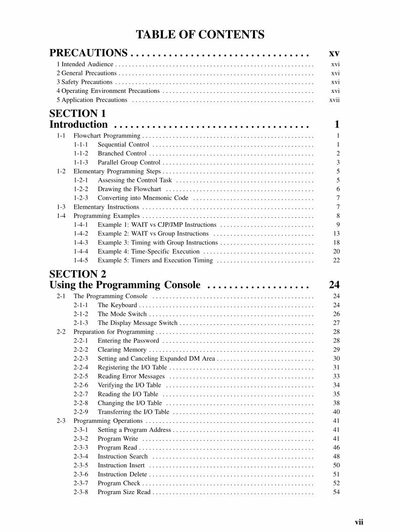
TABLE OF CONTENTS
vii
PRECAUTIONS xv. . . . . . . . . . . . . . . . . . . . . . . . . . . . . . . . . 1 Intended Audience xvi. . . . . . . . . . . . . . . . . . . . . . . . . . . . . . . . . . . . . . . . . . . . . . . . . . . . . . . . . . . 2 General Precautions xvi. . . . . . . . . . . . . . . . . . . . . . . . . . . . . . . . . . . . . . . . . . . . . . . . . . . . . . . . . . 3 Safety Precautions xvi. . . . . . . . . . . . . . . . . . . . . . . . . . . . . . . . . . . . . . . . . . . . . . . . . . . . . . . . . . . 4 Operating Environment Precautions xvi. . . . . . . . . . . . . . . . . . . . . . . . . . . . . . . . . . . . . . . . . . . . . 5 Application Precautions xvii. . . . . . . . . . . . . . . . . . . . . . . . . . . . . . . . . . . . . . . . . . . . . . . . . . . . . .
SECTION 1Introduction 1. . . . . . . . . . . . . . . . . . . . . . . . . . . . . . . . . . . .
1-1 Flowchart Programming 1. . . . . . . . . . . . . . . . . . . . . . . . . . . . . . . . . . . . . . . . . . . . . . . . . . . 1-1-1 Sequential Control 1. . . . . . . . . . . . . . . . . . . . . . . . . . . . . . . . . . . . . . . . . . . . . . . . 1-1-2 Branched Control 2. . . . . . . . . . . . . . . . . . . . . . . . . . . . . . . . . . . . . . . . . . . . . . . . . 1-1-3 Parallel Group Control 3. . . . . . . . . . . . . . . . . . . . . . . . . . . . . . . . . . . . . . . . . . . . .
1-2 Elementary Programming Steps 5. . . . . . . . . . . . . . . . . . . . . . . . . . . . . . . . . . . . . . . . . . . . . 1-2-1 Assessing the Control Task 5. . . . . . . . . . . . . . . . . . . . . . . . . . . . . . . . . . . . . . . . . 1-2-2 Drawing the Flowchart 6. . . . . . . . . . . . . . . . . . . . . . . . . . . . . . . . . . . . . . . . . . . . 1-2-3 Converting into Mnemonic Code 7. . . . . . . . . . . . . . . . . . . . . . . . . . . . . . . . . . . .
1-3 Elementary Instructions 7. . . . . . . . . . . . . . . . . . . . . . . . . . . . . . . . . . . . . . . . . . . . . . . . . . . 1-4 Programming Examples 8. . . . . . . . . . . . . . . . . . . . . . . . . . . . . . . . . . . . . . . . . . . . . . . . . . .
1-4-1 Example 1: WAIT vs CJP/JMP Instructions 9. . . . . . . . . . . . . . . . . . . . . . . . . . . . 1-4-2 Example 2: WAIT vs Group Instructions 13. . . . . . . . . . . . . . . . . . . . . . . . . . . . . . 1-4-3 Example 3: Timing with Group Instructions 18. . . . . . . . . . . . . . . . . . . . . . . . . . . . 1-4-4 Example 4: Time-Specific Execution 20. . . . . . . . . . . . . . . . . . . . . . . . . . . . . . . . . 1-4-5 Example 5: Timers and Execution Timing 22. . . . . . . . . . . . . . . . . . . . . . . . . . . . .
SECTION 2Using the Programming Console 24. . . . . . . . . . . . . . . . . . .
2-1 The Programming Console 24. . . . . . . . . . . . . . . . . . . . . . . . . . . . . . . . . . . . . . . . . . . . . . . . 2-1-1 The Keyboard 24. . . . . . . . . . . . . . . . . . . . . . . . . . . . . . . . . . . . . . . . . . . . . . . . . . . . 2-1-2 The Mode Switch 26. . . . . . . . . . . . . . . . . . . . . . . . . . . . . . . . . . . . . . . . . . . . . . . . . 2-1-3 The Display Message Switch 27. . . . . . . . . . . . . . . . . . . . . . . . . . . . . . . . . . . . . . . .
2-2 Preparation for Programming 28. . . . . . . . . . . . . . . . . . . . . . . . . . . . . . . . . . . . . . . . . . . . . . . 2-2-1 Entering the Password 28. . . . . . . . . . . . . . . . . . . . . . . . . . . . . . . . . . . . . . . . . . . . . 2-2-2 Clearing Memory 29. . . . . . . . . . . . . . . . . . . . . . . . . . . . . . . . . . . . . . . . . . . . . . . . . 2-2-3 Setting and Canceling Expanded DM Area 30. . . . . . . . . . . . . . . . . . . . . . . . . . . . . 2-2-4 Registering the I/O Table 31. . . . . . . . . . . . . . . . . . . . . . . . . . . . . . . . . . . . . . . . . . . 2-2-5 Reading Error Messages 33. . . . . . . . . . . . . . . . . . . . . . . . . . . . . . . . . . . . . . . . . . . 2-2-6 Verifying the I/O Table 34. . . . . . . . . . . . . . . . . . . . . . . . . . . . . . . . . . . . . . . . . . . . 2-2-7 Reading the I/O Table 35. . . . . . . . . . . . . . . . . . . . . . . . . . . . . . . . . . . . . . . . . . . . . 2-2-8 Changing the I/O Table 38. . . . . . . . . . . . . . . . . . . . . . . . . . . . . . . . . . . . . . . . . . . . 2-2-9 Transferring the I/O Table 40. . . . . . . . . . . . . . . . . . . . . . . . . . . . . . . . . . . . . . . . . .
2-3 Programming Operations 41. . . . . . . . . . . . . . . . . . . . . . . . . . . . . . . . . . . . . . . . . . . . . . . . . . 2-3-1 Setting a Program Address 41. . . . . . . . . . . . . . . . . . . . . . . . . . . . . . . . . . . . . . . . . . 2-3-2 Program Write 41. . . . . . . . . . . . . . . . . . . . . . . . . . . . . . . . . . . . . . . . . . . . . . . . . . . 2-3-3 Program Read 46. . . . . . . . . . . . . . . . . . . . . . . . . . . . . . . . . . . . . . . . . . . . . . . . . . . . 2-3-4 Instruction Search 48. . . . . . . . . . . . . . . . . . . . . . . . . . . . . . . . . . . . . . . . . . . . . . . . 2-3-5 Instruction Insert 50. . . . . . . . . . . . . . . . . . . . . . . . . . . . . . . . . . . . . . . . . . . . . . . . . 2-3-6 Instruction Delete 51. . . . . . . . . . . . . . . . . . . . . . . . . . . . . . . . . . . . . . . . . . . . . . . . . 2-3-7 Program Check 52. . . . . . . . . . . . . . . . . . . . . . . . . . . . . . . . . . . . . . . . . . . . . . . . . . . 2-3-8 Program Size Read 54. . . . . . . . . . . . . . . . . . . . . . . . . . . . . . . . . . . . . . . . . . . . . . . .

TABLE OF CONTENTS
viii
2-4 Monitor and Data Change Operations 55. . . . . . . . . . . . . . . . . . . . . . . . . . . . . . . . . . . . . . . . 2-4-1 Force Set/Reset 59. . . . . . . . . . . . . . . . . . . . . . . . . . . . . . . . . . . . . . . . . . . . . . . . . . 2-4-2 Channel Data Changes 59. . . . . . . . . . . . . . . . . . . . . . . . . . . . . . . . . . . . . . . . . . . . . 2-4-3 Single Channel Operations in Binary 60. . . . . . . . . . . . . . . . . . . . . . . . . . . . . . . . . 2-4-4 Three-Channel Operations 62. . . . . . . . . . . . . . . . . . . . . . . . . . . . . . . . . . . . . . . . . . 2-4-5 Group Monitor 64. . . . . . . . . . . . . . . . . . . . . . . . . . . . . . . . . . . . . . . . . . . . . . . . . . .
2-5 Debugging 66. . . . . . . . . . . . . . . . . . . . . . . . . . . . . . . . . . . . . . . . . . . . . . . . . . . . . . . . . . . . . 2-5-1 Step Execution 67. . . . . . . . . . . . . . . . . . . . . . . . . . . . . . . . . . . . . . . . . . . . . . . . . . . 2-5-2 Section Execution 69. . . . . . . . . . . . . . . . . . . . . . . . . . . . . . . . . . . . . . . . . . . . . . . . 2-5-3 Step Trace 71. . . . . . . . . . . . . . . . . . . . . . . . . . . . . . . . . . . . . . . . . . . . . . . . . . . . . .
2-6 File Memory Operations 73. . . . . . . . . . . . . . . . . . . . . . . . . . . . . . . . . . . . . . . . . . . . . . . . . . 2-6-1 File Memory Clear 73. . . . . . . . . . . . . . . . . . . . . . . . . . . . . . . . . . . . . . . . . . . . . . . . 2-6-2 File Memory Write 74. . . . . . . . . . . . . . . . . . . . . . . . . . . . . . . . . . . . . . . . . . . . . . . . 2-6-3 File Memory Verify 76. . . . . . . . . . . . . . . . . . . . . . . . . . . . . . . . . . . . . . . . . . . . . . . 2-6-4 File Memory Read 78. . . . . . . . . . . . . . . . . . . . . . . . . . . . . . . . . . . . . . . . . . . . . . . . 2-6-5 File Memory Read/Write 80. . . . . . . . . . . . . . . . . . . . . . . . . . . . . . . . . . . . . . . . . . . 2-6-6 File Memory Index Read 82. . . . . . . . . . . . . . . . . . . . . . . . . . . . . . . . . . . . . . . . . . .
2-7 Cassette Tape Operations 83. . . . . . . . . . . . . . . . . . . . . . . . . . . . . . . . . . . . . . . . . . . . . . . . . . 2-7-1 Saving a Program to Tape 84. . . . . . . . . . . . . . . . . . . . . . . . . . . . . . . . . . . . . . . . . . 2-7-2 Restoring Program Data 85. . . . . . . . . . . . . . . . . . . . . . . . . . . . . . . . . . . . . . . . . . . . 2-7-3 Verifying Program Data 86. . . . . . . . . . . . . . . . . . . . . . . . . . . . . . . . . . . . . . . . . . . . 2-7-4 DM<–> Cassette Tape: Save, Restore, and Verify 88. . . . . . . . . . . . . . . . . . . . . . .
SECTION 3Data and Memory Areas 90. . . . . . . . . . . . . . . . . . . . . . . . . .
3-1 Overview 90. . . . . . . . . . . . . . . . . . . . . . . . . . . . . . . . . . . . . . . . . . . . . . . . . . . . . . . . . . . . . . 3-2 I/O and Internal Relay Area - IR 91. . . . . . . . . . . . . . . . . . . . . . . . . . . . . . . . . . . . . . . . . . . . 3-3 Special Relay Area SR 95. . . . . . . . . . . . . . . . . . . . . . . . . . . . . . . . . . . . . . . . . . . . . . . . . . . .
3-3-1 Group Continue Control Bit 96. . . . . . . . . . . . . . . . . . . . . . . . . . . . . . . . . . . . . . . . 3-3-2 Data Retention Control Bit 97. . . . . . . . . . . . . . . . . . . . . . . . . . . . . . . . . . . . . . . . . 3-3-3 Output OFF Bit 97. . . . . . . . . . . . . . . . . . . . . . . . . . . . . . . . . . . . . . . . . . . . . . . . . . 3-3-4 FAL Error Code Output Area 97. . . . . . . . . . . . . . . . . . . . . . . . . . . . . . . . . . . . . . . 3-3-5 Battery Alarm Flag 97. . . . . . . . . . . . . . . . . . . . . . . . . . . . . . . . . . . . . . . . . . . . . . . 3-3-6 Indirect Jump Error Flag 97. . . . . . . . . . . . . . . . . . . . . . . . . . . . . . . . . . . . . . . . . . . 3-3-7 I/O Verification Error Flag 97. . . . . . . . . . . . . . . . . . . . . . . . . . . . . . . . . . . . . . . . . . 3-3-8 DM Address Error Flag 97. . . . . . . . . . . . . . . . . . . . . . . . . . . . . . . . . . . . . . . . . . . . 3-3-9 Instruction Execution Error Flag, ER 98. . . . . . . . . . . . . . . . . . . . . . . . . . . . . . . . . 3-3-10 Arithmetic Operation Flags 98. . . . . . . . . . . . . . . . . . . . . . . . . . . . . . . . . . . . . . . . . 3-3-11 Clock Bits 98. . . . . . . . . . . . . . . . . . . . . . . . . . . . . . . . . . . . . . . . . . . . . . . . . . . . . . . 3-3-12 Special I/O Flags and Control Bits 99. . . . . . . . . . . . . . . . . . . . . . . . . . . . . . . . . . .
3-4 Holding Relay Area - HR 102. . . . . . . . . . . . . . . . . . . . . . . . . . . . . . . . . . . . . . . . . . . . . . . . . . 3-5 Auxiliary Relay Area - AR 102. . . . . . . . . . . . . . . . . . . . . . . . . . . . . . . . . . . . . . . . . . . . . . . . 3-6 Link Relay Area - LR 106. . . . . . . . . . . . . . . . . . . . . . . . . . . . . . . . . . . . . . . . . . . . . . . . . . . . . 3-7 Timer/Counter Area - TC 107. . . . . . . . . . . . . . . . . . . . . . . . . . . . . . . . . . . . . . . . . . . . . . . . . . 3-8 Data Memory Area - DM 107. . . . . . . . . . . . . . . . . . . . . . . . . . . . . . . . . . . . . . . . . . . . . . . . . . 3-9 Program Memory 108. . . . . . . . . . . . . . . . . . . . . . . . . . . . . . . . . . . . . . . . . . . . . . . . . . . . . . . . 3-10 File Memory Area - FM 108. . . . . . . . . . . . . . . . . . . . . . . . . . . . . . . . . . . . . . . . . . . . . . . . . . .
SECTION 4Programming Instructions 110. . . . . . . . . . . . . . . . . . . . . . . .
4-1 Introduction 110. . . . . . . . . . . . . . . . . . . . . . . . . . . . . . . . . . . . . . . . . . . . . . . . . . . . . . . . . . . . 4-1-1 Inputting Instructions 110. . . . . . . . . . . . . . . . . . . . . . . . . . . . . . . . . . . . . . . . . . . . . . 4-1-2 Instruction Operand Data Areas and Flags 111. . . . . . . . . . . . . . . . . . . . . . . . . . . . .

TABLE OF CONTENTS
ix
4-2 Basic Instructions 113. . . . . . . . . . . . . . . . . . . . . . . . . . . . . . . . . . . . . . . . . . . . . . . . . . . . . . . . 4-2-1 LD, AND, OR, OUT, and NOT 113. . . . . . . . . . . . . . . . . . . . . . . . . . . . . . . . . . . . . . 4-2-2 Conditional Output - OUTC(00) and OUTC(00) NOT 115. . . . . . . . . . . . . . . . . . . . 4-2-3 Interlock - IL(38)<02> and ILC(39)<03> 116. . . . . . . . . . . . . . . . . . . . . . . . . . . . . . 4-2-4 Differentiation - DIFU(40)<13> and DIFD(41)<14> 116. . . . . . . . . . . . . . . . . . . . . 4-2-5 No Operation - NOP 118. . . . . . . . . . . . . . . . . . . . . . . . . . . . . . . . . . . . . . . . . . . . . .
4-3 Flow Control 119. . . . . . . . . . . . . . . . . . . . . . . . . . . . . . . . . . . . . . . . . . . . . . . . . . . . . . . . . . . . 4-3-1 WAIT and WAIT NOT 119. . . . . . . . . . . . . . . . . . . . . . . . . . . . . . . . . . . . . . . . . . . . . 4-3-2 Label - LBL 120. . . . . . . . . . . . . . . . . . . . . . . . . . . . . . . . . . . . . . . . . . . . . . . . . . . . . 4-3-3 Jump - JMP 120. . . . . . . . . . . . . . . . . . . . . . . . . . . . . . . . . . . . . . . . . . . . . . . . . . . . . 4-3-4 Conditional Jump - CJP and CJP NOT 121. . . . . . . . . . . . . . . . . . . . . . . . . . . . . . . . 4-3-5 Repeat - RPT(37) 122. . . . . . . . . . . . . . . . . . . . . . . . . . . . . . . . . . . . . . . . . . . . . . . . . 4-3-6 Conditional Skip - SKIP(46) and SKIP(46) NOT 124. . . . . . . . . . . . . . . . . . . . . . . . 4-3-7 Branch for Zero - BRZ(59) and BRZ(59) NOT 124. . . . . . . . . . . . . . . . . . . . . . . . .
4-4 Timers and Counters 125. . . . . . . . . . . . . . . . . . . . . . . . . . . . . . . . . . . . . . . . . . . . . . . . . . . . . 4-4-1 Timer - TIM 126. . . . . . . . . . . . . . . . . . . . . . . . . . . . . . . . . . . . . . . . . . . . . . . . . . . . . 4-4-2 Timer Start - TMS(30) 128. . . . . . . . . . . . . . . . . . . . . . . . . . . . . . . . . . . . . . . . . . . . . 4-4-3 Counter - CNT 129. . . . . . . . . . . . . . . . . . . . . . . . . . . . . . . . . . . . . . . . . . . . . . . . . . . 4-4-4 Reversible Counter - CNTR <12> 131. . . . . . . . . . . . . . . . . . . . . . . . . . . . . . . . . . . . 4-4-5 Programming Extended Timers and Counters 132. . . . . . . . . . . . . . . . . . . . . . . . . . . 4-4-6 Timer/Counter Reset - CNR 134. . . . . . . . . . . . . . . . . . . . . . . . . . . . . . . . . . . . . . . . 4-4-7 Multi-output Timer MTIM(80) 134. . . . . . . . . . . . . . . . . . . . . . . . . . . . . . . . . . . . . .
4-5 Data Shifting 135. . . . . . . . . . . . . . . . . . . . . . . . . . . . . . . . . . . . . . . . . . . . . . . . . . . . . . . . . . . 4-5-1 Shift Register - SFT 135. . . . . . . . . . . . . . . . . . . . . . . . . . . . . . . . . . . . . . . . . . . . . . . 4-5-2 Reversible Shift Register - SFTR<84> 138. . . . . . . . . . . . . . . . . . . . . . . . . . . . . . . . 4-5-3 Arithmetic Shift Left - ASL(63)<25> 139. . . . . . . . . . . . . . . . . . . . . . . . . . . . . . . . . 4-5-4 Arithmetic Shift Right - ASR(62)<26> 139. . . . . . . . . . . . . . . . . . . . . . . . . . . . . . . . 4-5-5 Rotate Left - ROL(70)<27> 140. . . . . . . . . . . . . . . . . . . . . . . . . . . . . . . . . . . . . . . . . 4-5-6 Rotate Right - ROR(69)<28> 140. . . . . . . . . . . . . . . . . . . . . . . . . . . . . . . . . . . . . . . 4-5-7 One Digit Shift Left - SLD(75)<74> 141. . . . . . . . . . . . . . . . . . . . . . . . . . . . . . . . . . 4-5-8 One Digit Shift Right - SRD(76)<75> 142. . . . . . . . . . . . . . . . . . . . . . . . . . . . . . . . . 4-5-9 Word Shift - WSFT(94)<16> 142. . . . . . . . . . . . . . . . . . . . . . . . . . . . . . . . . . . . . . . .
4-6 Data Movement 143. . . . . . . . . . . . . . . . . . . . . . . . . . . . . . . . . . . . . . . . . . . . . . . . . . . . . . . . . 4-6-1 Move - MOV(50)<21> and Move Not - MVN(51)<22> 143. . . . . . . . . . . . . . . . . . 4-6-2 Block Set - BSET(73)<71> 144. . . . . . . . . . . . . . . . . . . . . . . . . . . . . . . . . . . . . . . . . 4-6-3 Block Transfer - XFER(72)<70> 145. . . . . . . . . . . . . . . . . . . . . . . . . . . . . . . . . . . . . 4-6-4 Move Bit - MOVB<82> 146. . . . . . . . . . . . . . . . . . . . . . . . . . . . . . . . . . . . . . . . . . . . 4-6-5 Move Digit - MOVD<83> 147. . . . . . . . . . . . . . . . . . . . . . . . . . . . . . . . . . . . . . . . . . 4-6-6 Data Exchange - XCHG(74)<73> 149. . . . . . . . . . . . . . . . . . . . . . . . . . . . . . . . . . . . 4-6-7 Single Channel Distribution - DIST<80> 150. . . . . . . . . . . . . . . . . . . . . . . . . . . . . . 4-6-8 Data Collection - COLL<81> 151. . . . . . . . . . . . . . . . . . . . . . . . . . . . . . . . . . . . . . .
4-7 Data Comparison 152. . . . . . . . . . . . . . . . . . . . . . . . . . . . . . . . . . . . . . . . . . . . . . . . . . . . . . . . 4-7-1 Compare - CMP(52)<20> 152. . . . . . . . . . . . . . . . . . . . . . . . . . . . . . . . . . . . . . . . . . 4-7-2 Compare Long- CMPL<60> 154. . . . . . . . . . . . . . . . . . . . . . . . . . . . . . . . . . . . . . . . 4-7-3 Block Compare - BCMP<68> 154. . . . . . . . . . . . . . . . . . . . . . . . . . . . . . . . . . . . . . . 4-7-4 Table Compare - TCMP<85> 155. . . . . . . . . . . . . . . . . . . . . . . . . . . . . . . . . . . . . . .
4-8 Data Conversion 156. . . . . . . . . . . . . . . . . . . . . . . . . . . . . . . . . . . . . . . . . . . . . . . . . . . . . . . . . 4-8-1 BCD to Binary - BIN(57)<23> 156. . . . . . . . . . . . . . . . . . . . . . . . . . . . . . . . . . . . . . 4-8-2 BCD to Double Binary - BINL<58> 157. . . . . . . . . . . . . . . . . . . . . . . . . . . . . . . . . . 4-8-3 Binary to BCD - BCD(58)<24> 157. . . . . . . . . . . . . . . . . . . . . . . . . . . . . . . . . . . . . . 4-8-4 Double Binary to Double BCD - BCDL<59> 158. . . . . . . . . . . . . . . . . . . . . . . . . . . 4-8-5 4 to 16 Decoder - MLPX(77)<76> 158. . . . . . . . . . . . . . . . . . . . . . . . . . . . . . . . . . . 4-8-6 Encoder - DMPX(78)<77> 160. . . . . . . . . . . . . . . . . . . . . . . . . . . . . . . . . . . . . . . . . 4-8-7 Seven-Segment Decoder - SDEC(79)<78> 162. . . . . . . . . . . . . . . . . . . . . . . . . . . . . 4-8-8 ASCII Code Conversion - ASC<86> 164. . . . . . . . . . . . . . . . . . . . . . . . . . . . . . . . . . 4-8-9 Bit Counter - BCNT<67> 166. . . . . . . . . . . . . . . . . . . . . . . . . . . . . . . . . . . . . . . . . .

TABLE OF CONTENTS
x
4-9 BCD Calculations 168. . . . . . . . . . . . . . . . . . . . . . . . . . . . . . . . . . . . . . . . . . . . . . . . . . . . . . . . 4-9-1 Increment - INC(60)<38> 168. . . . . . . . . . . . . . . . . . . . . . . . . . . . . . . . . . . . . . . . . . 4-9-2 Decrement - DEC(61)<39> 170. . . . . . . . . . . . . . . . . . . . . . . . . . . . . . . . . . . . . . . . . 4-9-3 Set Carry - STC(95)<40> and Clear Carry - CLC(96)<41> 170. . . . . . . . . . . . . . . . 4-9-4 BCD Add - ADD(53)<30> 171. . . . . . . . . . . . . . . . . . . . . . . . . . . . . . . . . . . . . . . . . 4-9-5 Double BCD Add - ADDL<54> 172. . . . . . . . . . . . . . . . . . . . . . . . . . . . . . . . . . . . . 4-9-6 BCD Subtract - SUB(54)<31> 173. . . . . . . . . . . . . . . . . . . . . . . . . . . . . . . . . . . . . . . 4-9-7 Double BCD Subtract - SUBL<55> 175. . . . . . . . . . . . . . . . . . . . . . . . . . . . . . . . . . 4-9-8 BCD Multiply - MUL(55)<32> 176. . . . . . . . . . . . . . . . . . . . . . . . . . . . . . . . . . . . . . 4-9-9 Double BCD Multiply - MULL<56> 177. . . . . . . . . . . . . . . . . . . . . . . . . . . . . . . . . 4-9-10 BCD Divide - DIV(56)<33> 177. . . . . . . . . . . . . . . . . . . . . . . . . . . . . . . . . . . . . . . . 4-9-11 Double BCD Divide - DIVL<57> 178. . . . . . . . . . . . . . . . . . . . . . . . . . . . . . . . . . . . 4-9-12 Floating Point Divide - FDIV<79> 179. . . . . . . . . . . . . . . . . . . . . . . . . . . . . . . . . . . 4-9-13 Square Root - ROOT(64)<72> 182. . . . . . . . . . . . . . . . . . . . . . . . . . . . . . . . . . . . . .
4-10 Binary Calculations 182. . . . . . . . . . . . . . . . . . . . . . . . . . . . . . . . . . . . . . . . . . . . . . . . . . . . . . 4-10-1 Binary Increment - INCB<61> 183. . . . . . . . . . . . . . . . . . . . . . . . . . . . . . . . . . . . . . 4-10-2 Binary Decrement - DECB<62> 183. . . . . . . . . . . . . . . . . . . . . . . . . . . . . . . . . . . . . 4-10-3 Binary Addition - ADB<50> 184. . . . . . . . . . . . . . . . . . . . . . . . . . . . . . . . . . . . . . . . 4-10-4 Binary Subtraction - SBB<51> 184. . . . . . . . . . . . . . . . . . . . . . . . . . . . . . . . . . . . . . 4-10-5 Binary Multiplication - MLB<52> 185. . . . . . . . . . . . . . . . . . . . . . . . . . . . . . . . . . . 4-10-6 Binary Division - DVB<53> 185. . . . . . . . . . . . . . . . . . . . . . . . . . . . . . . . . . . . . . . . 4-10-7 Numeric Conversions -FUN<69> 186. . . . . . . . . . . . . . . . . . . . . . . . . . . . . . . . . . . .
4-11 Logic Instructions 188. . . . . . . . . . . . . . . . . . . . . . . . . . . . . . . . . . . . . . . . . . . . . . . . . . . . . . . . 4-11-1 Complement - COM(71)<29> 188. . . . . . . . . . . . . . . . . . . . . . . . . . . . . . . . . . . . . . . 4-11-2 Logical AND - ANDW(65)<34> 189. . . . . . . . . . . . . . . . . . . . . . . . . . . . . . . . . . . . . 4-11-3 Logical OR - ORW(66)<35> 189. . . . . . . . . . . . . . . . . . . . . . . . . . . . . . . . . . . . . . . . 4-11-4 Exclusive OR - XORW(67)<36> 190. . . . . . . . . . . . . . . . . . . . . . . . . . . . . . . . . . . . . 4-11-5 Exclusive NOR - XNRW(68)<37> 190. . . . . . . . . . . . . . . . . . . . . . . . . . . . . . . . . . .
4-12 Group Programs 191. . . . . . . . . . . . . . . . . . . . . . . . . . . . . . . . . . . . . . . . . . . . . . . . . . . . . . . . . 4-12-1 Basic Instructions - GN(10), GS(11), GE(12), GOFF(15), and GJ(17) 191. . . . . . . 4-12-2 Group Pause - GP(13) and Group Restart - GR(14) 197. . . . . . . . . . . . . . . . . . . . . . 4-12-3 Group Continue - GC(16) 197. . . . . . . . . . . . . . . . . . . . . . . . . . . . . . . . . . . . . . . . . . 4-12-4 AND Group - ANDG(01) and OR Group - ORG(02) 199. . . . . . . . . . . . . . . . . . . . .
4-13 Subroutines and Interrupt Control 199. . . . . . . . . . . . . . . . . . . . . . . . . . . . . . . . . . . . . . . . . . . 4-13-1 Overview 199. . . . . . . . . . . . . . . . . . . . . . . . . . . . . . . . . . . . . . . . . . . . . . . . . . . . . . . 4-13-2 Subroutine Definition - SBN(31)<92> and RET(33)<93> 200. . . . . . . . . . . . . . . . . 4-13-3 Subroutine Entry - SBS(32)<91> 200. . . . . . . . . . . . . . . . . . . . . . . . . . . . . . . . . . . . 4-13-4 Subroutine Test - SBT(34) 201. . . . . . . . . . . . . . . . . . . . . . . . . . . . . . . . . . . . . . . . . . 4-13-5 Interrupt Routines 202. . . . . . . . . . . . . . . . . . . . . . . . . . . . . . . . . . . . . . . . . . . . . . . . 4-13-6 Interrupt Control - MSKS(42) and CLI(43) 204. . . . . . . . . . . . . . . . . . . . . . . . . . . . 4-13-7 Mask Read - MSKR(45) 206. . . . . . . . . . . . . . . . . . . . . . . . . . . . . . . . . . . . . . . . . . .
4-14 Special Instructions 207. . . . . . . . . . . . . . . . . . . . . . . . . . . . . . . . . . . . . . . . . . . . . . . . . . . . . . 4-14-1 Process Display - S(47) 208. . . . . . . . . . . . . . . . . . . . . . . . . . . . . . . . . . . . . . . . . . . . 4-14-2 Failure Alarm - FAL(35)<06> and Severe Failure Alarm - FALS(36)<07> 208. . . 4-14-3 System Definition - FUN<49> 210. . . . . . . . . . . . . . . . . . . . . . . . . . . . . . . . . . . . . .
4-15 Trace Operations 213. . . . . . . . . . . . . . . . . . . . . . . . . . . . . . . . . . . . . . . . . . . . . . . . . . . . . . . . 4-16 File Memory Instructions 214. . . . . . . . . . . . . . . . . . . . . . . . . . . . . . . . . . . . . . . . . . . . . . . . . .
4-16-1 File Memory Read - FILR<42> 215. . . . . . . . . . . . . . . . . . . . . . . . . . . . . . . . . . . . . . 4-16-2 File Memory Write - FILW<43> 216. . . . . . . . . . . . . . . . . . . . . . . . . . . . . . . . . . . . . 4-16-3 External Program Read - FILP<44> 217. . . . . . . . . . . . . . . . . . . . . . . . . . . . . . . . . .
4-17 Intelligent I/O Instructions 218. . . . . . . . . . . . . . . . . . . . . . . . . . . . . . . . . . . . . . . . . . . . . . . . . 4-17-1 Intelligent I/O Write - WRIT(87)<87> 218. . . . . . . . . . . . . . . . . . . . . . . . . . . . . . . . 4-17-2 Intelligent I/O Read - READ(88)<88> 221. . . . . . . . . . . . . . . . . . . . . . . . . . . . . . . .

TABLE OF CONTENTS
xi
4-18 Network Instructions 222. . . . . . . . . . . . . . . . . . . . . . . . . . . . . . . . . . . . . . . . . . . . . . . . . . . . . 4-18-1 Send - SEND(90)<90> 222. . . . . . . . . . . . . . . . . . . . . . . . . . . . . . . . . . . . . . . . . . . . . 4-18-2 Network Receive - RECV(98)<98> 224. . . . . . . . . . . . . . . . . . . . . . . . . . . . . . . . . . 4-18-3 About Network Send and Receive Operations 225. . . . . . . . . . . . . . . . . . . . . . . . . .
SECTION 5Execution Time and I/O Response Time 228. . . . . . . . . . . . .
5-1 Overall PC Operation 228. . . . . . . . . . . . . . . . . . . . . . . . . . . . . . . . . . . . . . . . . . . . . . . . . . . . . 5-2 Changing Time Allocations 230. . . . . . . . . . . . . . . . . . . . . . . . . . . . . . . . . . . . . . . . . . . . . . . . 5-3 Instruction Execution Times 232. . . . . . . . . . . . . . . . . . . . . . . . . . . . . . . . . . . . . . . . . . . . . . . 5-4 I/O Response Time 240. . . . . . . . . . . . . . . . . . . . . . . . . . . . . . . . . . . . . . . . . . . . . . . . . . . . . . .
5-4-1 CPU Rack Response Times 240. . . . . . . . . . . . . . . . . . . . . . . . . . . . . . . . . . . . . . . . . 5-4-2 Remote I/O Systems 242. . . . . . . . . . . . . . . . . . . . . . . . . . . . . . . . . . . . . . . . . . . . . . 5-4-3 PC Link Systems 243. . . . . . . . . . . . . . . . . . . . . . . . . . . . . . . . . . . . . . . . . . . . . . . . . 5-4-4 Host Link Systems 245. . . . . . . . . . . . . . . . . . . . . . . . . . . . . . . . . . . . . . . . . . . . . . . .
SECTION 6Error Messages and Troubleshooting 247. . . . . . . . . . . . . . .
6-1 Programmed Alarms and Error Messages 247. . . . . . . . . . . . . . . . . . . . . . . . . . . . . . . . . . . . . 6-2 Reading and Clearing Errors and Messages 248. . . . . . . . . . . . . . . . . . . . . . . . . . . . . . . . . . . 6-3 System Errors 249. . . . . . . . . . . . . . . . . . . . . . . . . . . . . . . . . . . . . . . . . . . . . . . . . . . . . . . . . . . 6-4 Program Input Errors 253. . . . . . . . . . . . . . . . . . . . . . . . . . . . . . . . . . . . . . . . . . . . . . . . . . . . . 6-5 Program Errors 254. . . . . . . . . . . . . . . . . . . . . . . . . . . . . . . . . . . . . . . . . . . . . . . . . . . . . . . . . . 6-6 File Memory and Cassette Tape Errors 255. . . . . . . . . . . . . . . . . . . . . . . . . . . . . . . . . . . . . . .
AppendicesA Standard Models 256. . . . . . . . . . . . . . . . . . . . . . . . . . . . . . . . . . . . . . . . . . . . . . . . . . . . . . . . . . . B Programming Console Operations 265. . . . . . . . . . . . . . . . . . . . . . . . . . . . . . . . . . . . . . . . . . . . . . C Programming Instructions 275. . . . . . . . . . . . . . . . . . . . . . . . . . . . . . . . . . . . . . . . . . . . . . . . . . . . D Error and Arithmetic Flag Operation 300. . . . . . . . . . . . . . . . . . . . . . . . . . . . . . . . . . . . . . . . . . . . E ASCII Codes 304. . . . . . . . . . . . . . . . . . . . . . . . . . . . . . . . . . . . . . . . . . . . . . . . . . . . . . . . . . . . . . F System Data Sheets 305. . . . . . . . . . . . . . . . . . . . . . . . . . . . . . . . . . . . . . . . . . . . . . . . . . . . . . . . .
Index 309. . . . . . . . . . . . . . . . . . . . . . . . . . . . . . . . . . . . . . . . . . Revision History 319. . . . . . . . . . . . . . . . . . . . . . . . . . . . . . . . .

xiii
About this Manual:
This manual describes the operation of the C1000HF Programmable Controller (PC)and includes thesections described below.
Please read this manual carefully and be sure you understand the information provided before attemptingto operate the C1000HF.
The OMRON C1000HF PC offers an effective way to automate processing. Manufacturing, assembly,packaging, and many other processes can be automated to save time and money. The C1000HF PC isequipped with programming instructions, data areas, and other features to control these processes direc-tly or remotely. Distributed control systems can also be designed to allow centralized monitoring and su-pervision of several separate controlled systems. Monitoring and supervising can also be done through ahost computer, connecting the controlled system to a data bank. It is thus possible to have adjustments insystem operation made automatically to compensate for requirement changes.
Section 1 introduces flowchart programming.
Section 2 focuses on how to use the Programming Console to prepare the system for programming, toenter program data, and to monitor system operations and program execution. If you are not using a Pro-gramming Console, you can skip this section.
Section 3 explains how I/O bits are used to identify individual I/O points and discusses the functions of thevarious types of data and memory areas in the PC.
Section 4 describes the instructions in the C1000HF’s instruction set individually.
Section 5 defines the execution time and I/O response time and shows how to calculate these quantities.Execution times for individual instructions are listed.
Section 6 lists the error messages displayed on the LCD of the Programming Console and describessoftware troubleshooting processes.
WARNING Failure to read and understand the information provided in this manual may result inpersonal injury or death, damage to the product, or product failure. Please read eachsection in its entirety and be sure you understand the information provided in the sectionand related sections before attempting any of the procedures or operations given.
!

xv
PRECAUTIONS
This section provides general precautions for using the C1000HF Programmable Controller (PC) and related devices.
The information contained in this section is important for the safe and reliable application of the Programmable Con-troller. You must read this section and understand the information contained before attempting to set up or operate aPC system.

!
!
!
!
!
4Operating Environment Precautions
xvi
1 Intended AudienceThis manual is intended for the following personnel, who must also have knowl-edge of electrical systems (an electrical engineer or the equivalent).
• Personnel in charge of installing FA systems.
• Personnel in charge of designing FA systems.
• Personnel in charge of managing FA systems and facilities.
2 General PrecautionsThe user must operate the product according to the performance specificationsdescribed in the operation manuals.
Before using the product under conditions which are not described in the manualor applying the product to nuclear control systems, railroad systems, aviationsystems, vehicles, combustion systems, medical equipment, amusement ma-chines, safety equipment, and other systems, machines, and equipment thatmay have a serious influence on lives and property if used improperly, consultyour OMRON representative.
Make sure that the ratings and performance characteristics of the product aresufficient for the systems, machines, and equipment, and be sure to provide thesystems, machines, and equipment with double safety mechanisms.
This manual provides information for programming and operating the Unit. Besure to read this manual before attempting to use the Unit and keep this manualclose at hand for reference during operation.
WARNING It is extremely important that a PC and all PC Units be used for the specifiedpurpose and under the specified conditions, especially in applications that candirectly or indirectly affect human life. You must consult with your OMRONrepresentative before applying a PC System to the above-mentionedapplications.
3 Safety Precautions
WARNING Do not attempt to take any Unit apart while the power is being supplied. Doing somay result in electric shock.
WARNING Do not touch any of the terminals or terminal blocks while the power is beingsupplied. Doing so may result in electric shock.
WARNING Do not attempt to disassemble, repair, or modify any Units. Any attempt to do somay result in malfunction, fire, or electric shock.
4 Operating Environment Precautions
Caution Do not operate the control system in the following locations:
• Locations subject to direct sunlight.
• Locations subject to temperatures or humidity outside the range specified inthe specifications.
• Locations subject to condensation as the result of severe changes in tempera-ture.

!
!
!
!
5Application Precautions
xvii
• Locations subject to corrosive or flammable gases.
• Locations subject to dust (especially iron dust) or salts.
• Locations subject to exposure to water, oil, or chemicals.
• Locations subject to shock or vibration.
Caution Take appropriate and sufficient countermeasures when installing systems in thefollowing locations:
• Locations subject to static electricity or other forms of noise.
• Locations subject to strong electromagnetic fields.
• Locations subject to possible exposure to radioactivity.
• Locations close to power supplies.
Caution The operating environment of the PC System can have a large effect on the lon-gevity and reliability of the system. Improper operating environments can lead tomalfunction, failure, and other unforeseeable problems with the PC System. Besure that the operating environment is within the specified conditions at installa-tion and remains within the specified conditions during the life of the system.
5 Application Precautions
WARNING Always heed these precautions. Failure to abide by the following precautionscould lead to serious or possibly fatal injury.
• Always ground the system to 100 Ω or less when installing the Units. Not con-necting to a ground of 100 Ω or less may result in electric shock.
• Always turn OFF the power supply to the PC before attempting any of the fol-lowing. Not turning OFF the power supply may result in malfunction or electricshock.
• Mounting or dismounting I/O Units, CPU Units, Memory Cassettes, or anyother Units.
• Assembling the Units.
• Setting DIP switches or rotary switches.
• Connecting cables or wiring the system.
• Connecting or disconnecting the connectors.
Caution Failure to abide by the following precautions could lead to faulty operation of thePC or the system, or could damage the PC or PC Units. Always heed these pre-cautions.
• Fail-safe measures must be taken by the customer to ensure safety in theevent of incorrect, missing, or abnormal signals caused by broken signal lines,momentary power interruptions, or other causes.
• Interlock circuits, limit circuits, and similar safety measures in external circuits(i.e., not in the Programmable Controller) must be provided by the customer.
• Always use the power supply voltages specified in the operation manuals. Anincorrect voltage may result in malfunction or burning.
• Take appropriate measures to ensure that the specified power with the ratedvoltage and frequency is supplied. Be particularly careful in places where thepower supply is unstable. An incorrect power supply may result in malfunction.
• Install external breakers and take other safety measures against short-circuit-ing in external wiring. Insufficient safety measures against short-circuiting mayresult in burning.

5Application Precautions
xviii
• Do not apply voltages to the Input Units in excess of the rated input voltage.Excess voltages may result in burning.
• Do not apply voltages or connect loads to the Output Units in excess of themaximum switching capacity. Excess voltage or loads may result in burning.
• Disconnect the functional ground terminal when performing withstand voltagetests. Not disconnecting the functional ground terminal may result in burning.
• Install the Units properly as specified in the operation manuals. Improperinstallation of the Units may result in malfunction.
• Be sure that all the mounting screws, terminal screws, and cable connectorscrews are tightened to the torque specified in the relevant manuals. Incorrecttightening torque may result in malfunction.
• Use crimp terminals for wiring. Do not connect bare stranded wires directly toterminals. Connection of bare stranded wires may result in burning.
• Wire all connections correctly.
• Double-check all wiring and switch settings before turning ON the power sup-ply. Incorrect wiring may result in burning.
• Mount Units only after checking terminal blocks and connectors completely.
• Be sure that the terminal blocks, Memory Units, expansion cables, and otheritems with locking devices are properly locked into place. Improper lockingmay result in malfunction.
• Check switch settings, the contents of the DM Area, and other preparationsbefore starting operation. Starting operation without the proper settings or datamay result in an unexpected operation.
• Check the user program for proper execution before actually running it on theUnit. Not checking the program may result in an unexpected operation.
• Confirm that no adverse effect will occur in the system before attempting any ofthe following. Not doing so may result in an unexpected operation.
• Changing the operating mode of the PC.
• Force-setting/force-resetting any bit in memory.
• Changing the present value of any word or any set value in memory.
• Resume operation only after transferring to the new CPU Unit the contents ofthe DM Area, HR Area, and other data required for resuming operation. Notdoing so may result in an unexpected operation.
• Do not pull on the cables or bend the cables beyond their natural limit. Doingeither of these may break the cables.
• Do not place objects on top of the cables or other wiring lines. Doing so maybreak the cables.
• When replacing parts, be sure to confirm that the rating of a new part is correct.Not doing so may result in malfunction or burning.
• Before touching a Unit, be sure to first touch a grounded metallic object in orderto discharge any static built-up. Not doing so may result in malfunction or dam-age.
1
SECTION 1Introduction
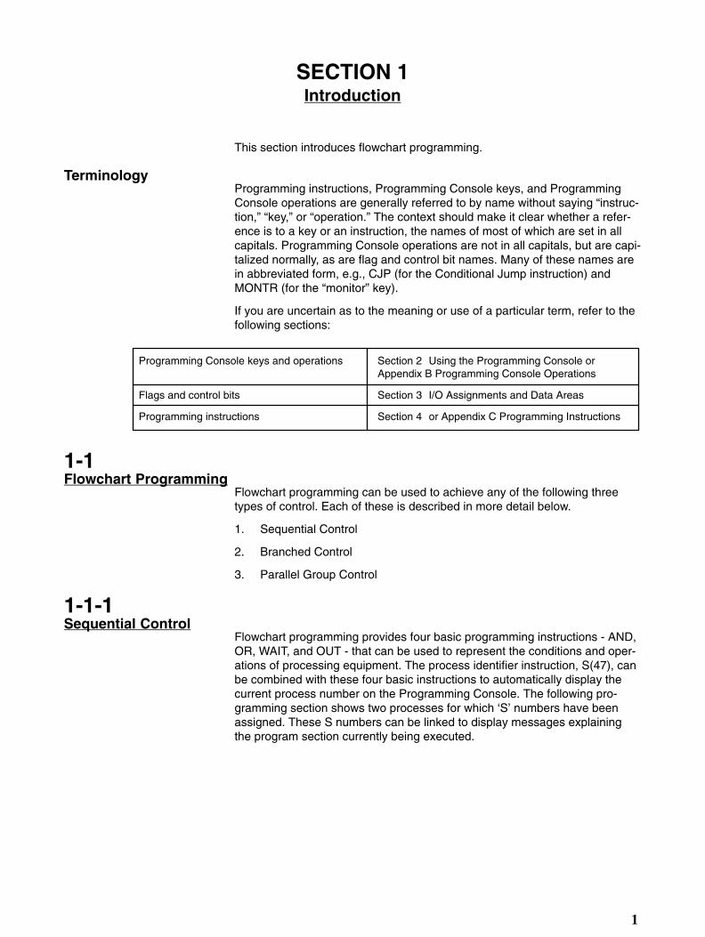
This section introduces flowchart programming.
TerminologyProgramming instructions, Programming Console keys, and ProgrammingConsole operations are generally referred to by name without saying “instruc-tion,” “key,” or “operation.” The context should make it clear whether a refer-ence is to a key or an instruction, the names of most of which are set in allcapitals. Programming Console operations are not in all capitals, but are capi-talized normally, as are flag and control bit names. Many of these names arein abbreviated form, e.g., CJP (for the Conditional Jump instruction) andMONTR (for the “monitor” key).
If you are uncertain as to the meaning or use of a particular term, refer to thefollowing sections:
Programming Console keys and operations
Flags and control bits
Programming instructions
Section 2 Using the Programming Console or Appendix B Programming Console Operations
Section 3 I/O Assignments and Data Areas
Section 4 or Appendix C Programming Instructions
1-1Flowchart Programming
Flowchart programming can be used to achieve any of the following threetypes of control. Each of these is described in more detail below.
1. Sequential Control
2. Branched Control
3. Parallel Group Control
1-1-1Sequential Control
Flowchart programming provides four basic programming instructions - AND,OR, WAIT, and OUT - that can be used to represent the conditions and oper-ations of processing equipment. The process identifier instruction, S(47), canbe combined with these four basic instructions to automatically display thecurrent process number on the Programming Console. The following pro-gramming section shows two processes for which ‘S’ numbers have beenassigned. These S numbers can be linked to display messages explainingthe program section currently being executed.

Introduction Section 1
2
Current ‘S’ number
S 0000
#0000
AND 00002
WAIT
OUT 00501
S 0001
#0000
AND 00004
AND 00005
WAIT
OUT 00503
Process 0
Process 1
Indicates start of process 0.
Indicates that input 00002 is the input condition.
Indicates a wait until the input condition is met, i.e., until input00002 comes ON.
Indicates that output 00501 is to go ON when input 00002 com-es ON.
Indicates the start of process 1. Automatically displayed on Pro-gramming Console as shown below.
1-1-2Branched Control
With flowchart programming, conditional jump (CJP) and label instructions(LBL) can be used to achieve branched control. This type of control closelyfollows the operation of processing equipment in terms of condition-responserequirements, as shown by the following example. The conditions and opera-tions shown at the left for a processing device can be programmed as shownat the right.

Section 1Introduction
3
Rotate arm counterclockwise.
Operations
Device
Conditions Operations
Grasp workpiece.
Rotate arm clockwise.
Release workpiece.
Start button pressed?
Workpiece in position?
Workpiece grasped?
Workpiece positioned?
Program
Conditions
CJP
CJP
CJP
CJP
LBL 0
AND PB1
AND LS3
JMP LBL0
AND LS2
OUT NOT SOL2
OUT NOT SOL3
JMP LBL0
AND LS1
YES
NO
YES
NO
YES
NO
YES
NO
LBL 1
OUT SOL1
JMP LBL2
OUT NOT SOL1
OUT SOL3
JMP LBL4
OUT SOL2
JMP LBL6
LBL 3
LBL 5
LBL 7
YES
NO
YES
NO
YES
NO
YES
NO
1-1-3Parallel Group Control
The C1000HF is equipped with seven group instructions (GN, GS, GE,GOFF, GP, GR, and GJ) that allow multiple processes to be controlled simul-taneously. These group instructions, in combination with the above-men-tioned S instruction, provide many advantages both in programming and inactual control.
Programming Advantages
The programming task can be divided into process groups to enable indepen-dent programming of small portions of the program. This not only simplifiesthe programming task, but also simplifies the structure of the program andreduces the possibility of programming errors. It also enables more than oneprogrammer to divide the programming task to reduce programming time re-
Introduction Section 1
4
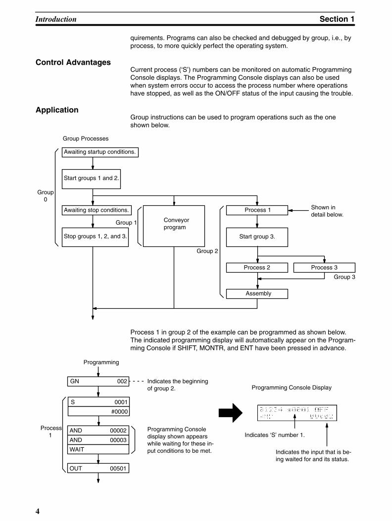
quirements. Programs can also be checked and debugged by group, i.e., byprocess, to more quickly perfect the operating system.
Control AdvantagesCurrent process (‘S’) numbers can be monitored on automatic ProgrammingConsole displays. The Programming Console displays can also be usedwhen system errors occur to access the process number where operationshave stopped, as well as the ON/OFF status of the input causing the trouble.
ApplicationGroup instructions can be used to program operations such as the oneshown below.
Awaiting startup conditions.
Start groups 1 and 2.
Awaiting stop conditions.
Stop groups 1, 2, and 3.
Group 3
Group Processes
Group 0
Group 1 Conveyorprogram
Group 2
Process 1
Start group 3.
Process 2
Assembly
Shown indetail below.
Process 3
Process 1 in group 2 of the example can be programmed as shown below.The indicated programming display will automatically appear on the Program-ming Console if SHIFT, MONTR, and ENT have been pressed in advance.
Programming
Process 1
Indicates the beginningof group 2.
Programming Consoledisplay shown appearswhile waiting for these in-put conditions to be met.
Programming Console Display
Indicates ‘S’ number 1.
Indicates the input that is be-ing waited for and its status.
GN 002
S 0001
#0000
AND 00002
AND 00003
WAIT
OUT 00501
Section 1Introduction
5
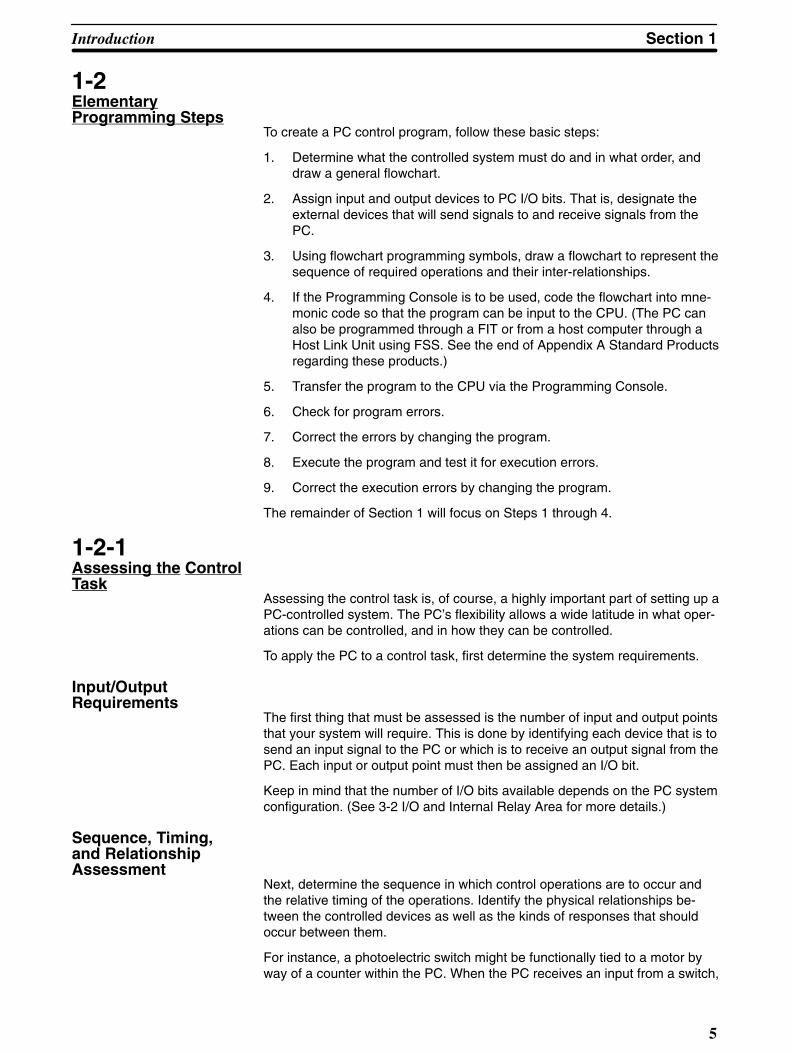
1-2ElementaryProgramming Steps
To create a PC control program, follow these basic steps:
1. Determine what the controlled system must do and in what order, anddraw a general flowchart.
2. Assign input and output devices to PC I/O bits. That is, designate theexternal devices that will send signals to and receive signals from thePC.
3. Using flowchart programming symbols, draw a flowchart to represent thesequence of required operations and their inter-relationships.
4. If the Programming Console is to be used, code the flowchart into mne-monic code so that the program can be input to the CPU. (The PC canalso be programmed through a FIT or from a host computer through aHost Link Unit using FSS. See the end of Appendix A Standard Productsregarding these products.)
5. Transfer the program to the CPU via the Programming Console.
6. Check for program errors.
7. Correct the errors by changing the program.
8. Execute the program and test it for execution errors.
9. Correct the execution errors by changing the program.
The remainder of Section 1 will focus on Steps 1 through 4.
1-2-1Assessing the ControlTask
Assessing the control task is, of course, a highly important part of setting up aPC-controlled system. The PC’s flexibility allows a wide latitude in what oper-ations can be controlled, and in how they can be controlled.
To apply the PC to a control task, first determine the system requirements.
Input/Output Requirements
The first thing that must be assessed is the number of input and output pointsthat your system will require. This is done by identifying each device that is tosend an input signal to the PC or which is to receive an output signal from thePC. Each input or output point must then be assigned an I/O bit.
Keep in mind that the number of I/O bits available depends on the PC systemconfiguration. (See 3-2 I/O and Internal Relay Area for more details.)
Sequence, Timing, and Relationship Assessment
Next, determine the sequence in which control operations are to occur andthe relative timing of the operations. Identify the physical relationships be-tween the controlled devices as well as the kinds of responses that shouldoccur between them.
For instance, a photoelectric switch might be functionally tied to a motor byway of a counter within the PC. When the PC receives an input from a switch,

Introduction Section 1
6
it starts the motor. The PC stops the motor when the counter has receivedfive input signals from the photoelectric switch.
Each of the related tasks must be similarly determined, from the beginning ofthe controlled operation to the end.
Having made this assessment, you will be ready to go to step 2 of program-ming-assigning the input/output devices to I/O bits.
Input/Output Assignments
The PC uses the concept of I/O channels. An I/O channel consists of 16 bits.
The five-digit number used to identify an I/O bit, also known as the address ofthe bit, can be broken down into two parts. The leftmost three digits identifythe channel, and the rightmost two digits identify the bit within the channel.See the discussion on addressing conventions in 3-1 I/O Assignments andData Areas.
Assigning Non-I/O IRBits
Bits that are not used to directly send or receive signals to or from externaldevices act as internal storage bits and are used to control other bits, timers,and counters. Assign these ‘work bits’ when you assign I/O bits during Step2.
Assigning Numbers toTimers and Counters
Identify timers and counters with a number that ranges from 000 to 511.
When assigning timer and counter numbers, be careful not to use the sametimer/counter number for another timer/counter. For example, there cannot bea Timer 001 and a Counter 001.
When you’re finished assigning the I/O bits, work bits, and timer/counter num-bers, proceed to the next step, drawing the Flowchart.
1-2-2Drawing the Flowchart
Once you have determined which devices are to be controlled, how they re-late to each other, and the sequence (or timing) at which the controlled tasksmust take place, draw a flowchart. Some examples of flowcharts are providedin 1-4 Programming Examples.
In the flowchart, use the five-digit addresses that you assigned to the I/O bitsand work bits, as well as the three-digit numbers you gave to the timers andcounters. You’ll also use flowchart symbols such as those shown for instruc-tions in Section 4 Programming Instructions. These consist basically of dia-mond-shaped boxes that represent conditional branches and rectangularboxes that designate inputs, outputs, and other control actions, as well astimers, counters, waits, and other program control steps.
conditional branches are used when the next step or steps to be taken in aprocess depend on certain conditions. There are other means of moving todifferent steps in a program, such as unconditional jumps and group pro-grams. All such jumps, and returns from them, require labels at the destina-tion of the jump or return.
Individual parts of the program consist of one line, or more than one linejoined directly. More than one instruction line joined directly, such as a seriesof AND or OR instructions establishing conditions for a WAIT or other opera-
Section 1Introduction
7
tion, is called a block. If these lines or blocks establish conditions determiningthe outcome of an instruction following them in the program, they are calledcondition lines or condition blocks. The lines or blocks that make up the pro-gram are joined with lines and arrows that indicate the flow of the program.Solid lines indicate direct moves through the program; dotted lines indicatemoves made through a program jump to a label.
When writing a complex flowchart, it is often convenient to make a generalflowchart first showing only the overall processes and their relationships toeach other. Here it is not even necessary to specify all of the instructions thatwill be used. Once a firm grasp of a general flowchart has been made, it canbe turned into a detailed flowchart showing the specific instructions that willbe used and including all labels that will be necessary to move around in theprogram.
When you have finished drawing your detailed flowchart, the next step is toencode the flowchart into a language that the PC can understand. This stepis necessary only if you are using a Programming Console to input the pro-gram.
1-2-3Converting intoMnemonic Code
When programming through the Programming Console, you must convert theflowchart into mnemonic code. If you are using FSS or a FIT (see AppendixA) for programming, you can directly program the PC in flowchart logic. Mne-monic code consists of addresses, instructions, and data.
“Addresses” in this context refers to program addresses-locations in the PC’sProgram Memory where instructions and data are stored. Instructions tell thePC what to do using the operand data that follows each instruction. Each in-struction is a step in the program, and address numbers provide a way to ref-erence steps. When programming, the addresses will automatically be dis-played and do not have to be set unless for some reason a different locationis desired.
Many of the programming examples offered later in this manual show conver-sions of instructions to mnemonic code. The individual codes are given foreach instruction in Section 4 and in Appendix C Programming Instructions.
To keep a program organized and enable it to execute properly, it is importantto input the mnemonic code in the correct order. First, input the main programline of the main program from start to finish. Then go back to the beginning ofthe program and input each branch leaving the main program line, beginningwith the label for it and ending with a return to the proper destination. Once allmain program branches have been input, input the first group program in or-der using the same procedure as for the main program, i.e., input the mainprogram line first, and then any branches starting back at the beginning of themain program line for that group program. Continue on in this fashion until allgroup programs have been input. You’re now ready to start testing the pro-gram.
1-3Elementary Instructions
Each of the indispensable elementary instructions has a corresponding keyon the Programming Console. These include AND, OR, NOT, WAIT, OUT,JMP, CJP, LBL, TIM, CNT, and CNR, any one of which can be entered simply

Introduction Section 1
8
by pressing the appropriate key. The other elementary instruction, LD, is inputby holding down the SFT key and pressing the AND key. See Section 4 Pro-gramming Instructions for details on these instructions.
LD and LD NOTLD or LD NOT starts a line or block of inputs. The first input can also bestarted with AND or OR. LD NOT indicates the opposite of the actual statusof the input.
AND and AND NOTAND or AND NOT is used to serially connect two or more inputs. AND NOTconnects the opposite of the actual status of the second input.
OR and OR NOTOR or OR NOT is used to connect two or more inputs in parallel. OR NOTconnects the opposite of the actual status of the second input.
AND LDAND LD connects two blocks in series. In other words, AND LD logicallyANDs the logical results of two blocks.
OR LDOR LD connects two blocks in parallel. In other words, OR LD logically ORsthe logical results of two blocks.
WAIT and WAIT NOTWAIT is used to pause operation flow until an input goes ON; WAIT NOT, untilan input goes OFF.
OUT and OUT NOTOUT is used to turn outputs ON; OUT NOT, to turn outputs OFF.
JMP, CJP, and LBLJMP is used to jump to other program locations; CJP, to branch programmingaccording to specific conditions; and LBL, to indicate branch and jump desti-nations.
TIM, CNT, and CNRTIM, CNT, and CNR are instructions for timers, counters, and reversiblecounters.
1-4Programming Examples
The following programming examples are designed to introduce basic pro-gramming techniques and instruction applications. All of these examplesshould be studied in detail to gain a thorough understanding of basic flow-chart programming.
Refer to Section 4 Programming Instructions for details on any instructionsused in following examples.

Section 1Introduction
9
1-4-1Example 1: WAIT vsCJP/JMP Instructions
An example control system will be programmed using first WAIT instructionsand then CJP and JMP instructions. In this example system, a bidirectionalcylinder is moved forward by electromagnetic valve 1 (MV1) when a pushbut-ton switch (PB) is pressed. Electromagnetic valve 2 (MV2) then moves thecylinder back to the back limit switch (LS1) 1.5 seconds after the front limitswitch (LS2) is activated. The setup and timing chart for this operation are asshown below.
PB
LS1
LS2
MV1
MV21.5 s
Setup
Back Forward
MV1 MV2
LS1 LS2
Timing Chart
WAIT InstructionsFirst the above operation is prepared in a general flowchart giving the overalloperation.
Conditions to turn MV2 OFF.
START
AND
ON
AND(OR)
OFF
TIM
ON
AND(OR)
OFF
END
LS1 ONPB ON
MV1 ON
LS2
MV1 OFF
1.5 s
MV2 ON
LS1 ON
MV2 OFF
Conditions to turn MV1 ON.
Conditions to turn MV2 ON.
Conditions to turn MV1 OFF.

Introduction Section 1
10
Then I/O points and timers/counters are assigned.
SymbolBit type
Input
Output
PB 00002
LS1 00003
LS2 00004
MV1 00500
MV2 00501
TIM 000 (1.5 s)
Bit #
Timer
Finally a detailed flowchart is prepared to be input via the Programming Con-sole.
Input from LS1
AND 00002
AND 00003
WAIT
OUT 00500
AND 00004
WAIT
OUT NOT 00500
TIM 000
#0015
WAIT
OUT 00501
AND 00003
WAIT
OUT NOT 00501
JMP LBL1
START
An AND between inputs from LS1 and PB
Input from LS2
The final JMP instruction and corresponding label (LBL1) are used to repeatthe operation from the beginning. Label LBL2 is input to allow for debuggingfrom the “OUT 00501” step of the program, and is not associated with a JMPinstruction.

Section 1Introduction
11
CJP and JMP Instructions
Although here only the general flowchart is presented, two important aspectsof branched programming using the CJP instruction are illustrated: program-ming timers and program input sequence. When writing the detailed flow-chart, labels must be added to designate all jump destinations.
OUT MV1
JMP
AND LS1
AND PB
CJP
AND LS2
CJP
OUT NOT MV1
AND MV2
CJP
TIM 0
15
CJP
JMP
OUT NOT MV2
JMP
AND LS1
CJP
OUT MV2
JMP
JMP
Yes
No
Yes
Yes
Yes
No
No
No
No
Yes
MV1 turned ON.
MV2 turned ON.
MV2 turned OFF.

Introduction Section 1
12
• Programming TimersCare must be taken in programming timers when using branching programs.Here the timer must be programmed so that is it on a branch line where it willbe activated only when MV2 is not already operating. If the “AND MV2” andfollowing “CJP” portions of the flowchart were to be eliminated from the pro-gram, the timer would be restarted before LS2 had time to turn OFF.
• Input SequenceProgram steps along the base line of the flowchart must always be input first,followed by program steps on branches flowing off of the base line in order asthey move down the base line. In the example sequence, the CJP instruc-tions (A, B, and C) indicated “1” would be input first, followed by the branch-ing program steps “2,” “3,” and then “4.”
Branch stepsYes
No
Yes
No
Yes
No
JMP
Branch steps JMP
Branch steps JMP
A
B
C
12
3
4

Section 1Introduction
13
1-4-2Example 2: WAIT vsGroup Instructions
An example control system will be programmed using first WAIT instructionsand then group instructions. In this example system, a bin moves forwardwhen a pushbutton (PB) is pressed. When limit switch 2 (LS2) is activated,the bin stops and a hopper opens for eight seconds. After eight seconds, thehopper closes, the bin returns to its original position, and the bottom of thebin opens for five seconds when limit switch 1 (LS1) is activated. This pro-cess is then repeated once before the program ends.
Back Forward
Hopper
LS1 LS2
The I/O point and timer/counter assignment for this system are as follows:
PB 00002
LS1 00003
LS2 00004
Hopper 00500
Forward 00501
Back 00502
Bin 00503
TIM (5 s and 8 s)
SymbolBit type
Input
Output
Bit #
Timer
AR bit 10000 will be used as a work bit to record completion of the first ex-ecution of the operation.
WAIT InstructionsThe flowchart for the above operation written using WAIT instructions wouldbe as shown on the following page.

Introduction Section 1
14
Flowchart
Bin moved forward.
Bin stopped.
Hopper opened.
Hopper closed.
Bin moved back.
Bin stopped.
Bin bottom opened.
Bin bottom closed.
YES (completion at 2nd execution)
START
Waiting for PB to come ON.
JMP LBL2
AND 00002
WAIT
OUT NOT 1000
OUT OO5O1
AND 00004
WAIT
OUT NOT 00501
OUT 00500
TIM 000
#0080
WAIT
OUT NOT 00500
OUT 00502
AND 00003
WAIT
OUT NOT 00502
OUT 00503
TIM 000
#0050
WAIT
OUT NOT 00503
AND 10000
CJP LBL1
OUT 10000
Waiting for LS2 to come ON.
8-second wait
Waiting for LS1 to come ON.
5-second wait.

Section 1Introduction
15
Group InstructionsHere a group is created so that an emergency stop input can be processed inthe main program, allowing normal operations, performed in the group pro-gram, to be stopped as soon as the emergency stop input is received. Thedetailed main program and the flow of the group program have been pro-vided. The following inputs are used in addition to those mentioned above.The start pushbutton is PB1.
Emergency stop pushbutton (PB2): 00005
Manual bin-return pushbutton (PB3): 00006
Manual/automatic selector for bin return (CS): 00007
The GJ instruction is used to jump to the group program. This is necessaryhere because the main program uses only branching instructions, creating aclosed loop.
The GOFF instruction serves to stop execution of the group. All timers and alloutputs from OUT and OUTC instructions in the group are reset when GOFFis executed. Values held in the DM area for counters, shift registers, and oth-er calculated values are not reset. (The CNR instruction can be used when itis necessary to reset a counter in a group.)
The GE instruction inserted at the end of group execution serves to reset thegroup so that the next execution of a GS instruction for it will begin the groupfrom its first step.
Group ProgramMain Program
START
Emergencystop (PB2) Group execution
stopped; groupoutputs OFF.
Manual/automatic selector (CS)
Yes
No
Manual
Automatic
Bin return whenPB3 is pressed.
GE 0
JMP LBL10
LBL10
LBL12
LBL13
LBL11
AND 00005
CJP LBL11
AND 00007
AND 00006
CJP LBL13
GS 0
GJ
JMP LBL10
G OFF 0
JMP LBL12
AND NOT 00003
OUTC 502
Yes
No
GN 0
AND 10000
CJP LBL1
JMP LBL2LBL1
LBL2
Instructions ofgroup program
Group ProgrammingConsiderations
1. Any operation, such as an emergency stop, that must take precedentover general operations must be placed in the main program.

Introduction Section 1
16
2. Group programs are stopped from the main program by inserting theGOFF into the main program. Executing this instruction turns OFF alloutputs made from the group program and stops timers and counters(timers are reset).
3. Groups must be started from the main program using the GS instruction.
4. The GN instruction is required at the beginning of all groups; the GE in-struction, at the end.
5. Although manual operations can be programmed within the main pro-gram as shown for returning the bin in the above example, these aregenerally programmed separately as illustrated below. Because manualoperations must respond to arbitrary control inputs, branched program-ming is usually most appropriate. It is generally best to insert instructionsto stop all group programs before entering manual operations and to turnall outputs OFF when switching between manual and automatic opera-tions.
The main program can be interlocked to groups andall groups interlocked to each other by using AR bits.
Yes
No
GN 7GN 0
GE 7GE 0
Manual?
Main program Group #0 Group #7
Manualoperations(branchedprogram-ming)
SimultaneousOperations
To initiate simultaneous execution of different operations part way through aprocess, a second group can be activated part way through execution of afirst group. An AR bit can then be used to interlock the two groups so thatexecution of a later portion of the first group can be coordinated with comple-tion of execution of the second group. The timing for operations performed inthese groups and a general flowchart that can be used to achieve proper con-trol are provided below.

Section 1Introduction
17
Group B ended.
Start
12
3
45
Operation Timing
Yes
No
Main Program
START
Groups A andB stopped.
Loads Aand B OFF.
Group A
Operation 1
Operation 2
Operation 3
Operation 4
Operation 5
Group B started.
AR bit ON
Waiting for AR bit. Waiting for comple-tion of operation 4.
AR bit OFF.
Group A ended.
GS A
GN A
AND
GJ
JMP
GS B
GN B
GE B
GE A
Group B

Introduction Section 1
18
1-4-3Example 3: Timing withGroup Instructions
This example, which programs a water fountain, shows how a main programcontrolling overall operation is executed simultaneously with a group programthat controls specific operations. The group program utilizes a timer and se-quential programming to achieve programming simplicity. Because sequential(WAIT) programming is used, the same timer (000) is used for all timed inter-vals. Overall operations are as follows:
1. When pushbutton PB1 is activated, jets C are turned on.
2. After five seconds, jets C are turned off and jets A and B are turned on.
3. After another five seconds, jets A are turned off.
4. After a further five seconds, jets B are turned off, and jets A and C areturned on.
5. After two seconds, jets B are turned back on.
6. After five seconds, all jets are turned off.
7. After two seconds, jets C are turned ON and step 2, above, is returnedto.
8. If pushbutton PB2 is activated, all jets are stopped and program execu-tion is halted.
Outputs 00500, 00501, and 00502 turn the jets on and off; inputs 00002 and00004 are from the pushbutton switches.
The timing chart, fountain setup, principle portions of the flowchart, and thecoding used to input this portion via the Programming Console are providedbelow.

Section 1Introduction
19
2s5s
5s
5s 5s
One scan2s
C
A
BB
A A
BB
B AA
Fountain Setup Timing Chart
Flowchart
START
Waiting for input of PB2.
Jets A turned off.
Jets B turned off.
Jets C turned off.
Waiting for input of PB1.
Jets C turned on.
Jets C turned off.
GS 0
AND 00004
WAIT
OUT NOT 00500
OUT NOT 00501
OUT NOT 00502
GN 0
CNR TIM 000
GE 0
JMP LBL1
AND 002
WAIT
OUT 00500
TIM 000
#00500
WAIT
OUT NOT 00500
TIM 000
#0020
WAIT
JMP LBL2

Introduction Section 1
20
Mnemonic Code
0000 LBL 0001
0001 GS 000
0002 AND 00004 PB2
0003 WAIT –––
0004 OUT NOT 00500
0005 OUT NOT 00501
0006 OUT NOT 00502
0007 CNR TIM 000
0008 GE 000
0009 JMP LBL 0001
0010 GN 000
0011 AND 00002 PB1
0012 WAIT –––
0013 LBL 0002
0014 OUT 00500
0015 TIM 000
# 0050 5 S
0016 WAIT –––
0017 OUT NOT 00500
0041 TIM 000
# 0020 2 S
0042 WAIT –––
0043 JMP LBL 0002
Address Instruction Data Comments
1-4-4Example 4: Time-SpecificExecution
The SR area clock bits (see 3-3 Special Relay Area - SR) can be used inDIFU or DIFD and combined with SKIP or SKIP NOT to control the timing ofprogram step execution.
In this example DIFU is combined with a 0.1-second clock pulse (SR bit22500) and SKIP NOT so that an input channel (010) is transferred to thespecified area of the DM area only when a ‘transfer’ pushbutton (PB, input00000) is ON.
The WSFT instruction is used to transfer the contents of channel 010 to DM1000, the contents of DM 1000 to DM 1001, the contents of DM 1001 to DM

Section 1Introduction
21
1002, etc. Because DM 2000 is the designated end channel, its contents arelost.
The contents of channel 010 are input via an Input Unit from a detector thattransfers four digits of BCD. The setup and program section for this operationare shown below. Note that the program is also set up to clear channels DM1000 through DM 2000 each time the transfer pushbutton is turned ON.
Setup
DM1000
DM2000
Detector
BCD (4 digits)
Input Unit
Ch 010
Program Section
One channel ofdata (4-digitBCD) shifted toDM 1000 every0.1 s.
Yes
No
Yes
No
Yes
No
DM 1000 throughDM 2000 clearedonce each timePB (00000) isturned ON.
Data transferredonly while PB(00000) is ON.
(0.1-sclock)
DIFU(40) 00
00000
WSFT(94)
010
DM1000
DM2000
SKIP NOT 1
CNR
DM1000
DM2000
AND 00000
SKIP NOT 3
DIFU(40) 01
25500
SKIP NOT 1

Introduction Section 1
22
Precautions for DIFU/DIFD Instructions
DIFU/DIFD must always be used with certain instructions, such as WSFT inthe above example, to ensure that the instruction is executed only at the de-sired time and only the desired number of times. If DIFU/DIFD is not used, aprogramming step activated by an SR area clock bit may be executed manytimes during the half of the pulse interval during which the clock bit is ON, i.e.,if the CPU processing time is shorter than the clock pulse.
If the CPU processing time is longer than the clock pulse, the reverse prob-lem can also occur, i.e., a programming step activated by DIFU/DIFD using aclock pulse may not be executed during a particular pulse. This can occurwhen a branch from a loop containing the DIFU/DIFD instruction jumps to agroup program. In such cases, scheduled interrupts must be used.
1-4-5Example 5: Timers andExecution Timing
Although little trouble is encountered in combining timers with WAIT in se-quential programming to allow time between programmed operations, at-tempting to achieve the same in branched or group programming can be diffi-cult (see Section 5 Execution Time and I/O Response Time for details on tim-ing).
Sequential ProgrammingThe following program section allows 1.00 second to elapse between opera-tions A and B.
Operation A
Hundredth of seconds
Operation B
TIM 400
#0100
WAIT
Group ProgrammingBecause group programs are jumped to for WAIT, the desired 1.00 secondbetween operations A and B will be exceeded in the following example if op-eration C requires longer than one second to process.

Section 1Introduction
23
TIM 400
#0100
WAIT
Operation A
Operation B
Operation C
GN
GE
Branched ProgrammingProper timing is also difficult to achieve if a CJP instruction is combined with atimer and the branch taken from the timer before time has expired is used forother operations. In the following example, operation B will not be started untilthe TIM instruction is executed after the timer has reached a present value ofzero, i.e., it will be delayed by the time required to finish processing operationC. The longer the processing time for operation C, the longer the possibledelay.
Operation B
TIM 400
#0100
Operation A
Operation C
Yes
No
CJP
TIM instructions are executed again after completing simultaneous program-ming steps in group programs entered through WAIT or GJ instructions. Tim-er accuracy can thus be affected by group execution conditions.

24
SECTION 2Using the Programming Console
This section focuses on how to use the Programming Console to prepare thesystem for programming, to enter program data, and to monitor system oper-ations and program execution. If you are not using a Programming Console,you can skip this section.
Note: It is assumed, unless otherwise indicated, that all operations inthis section begin with the display cleared to 00000 by pressingCLR. Any of the Programming Console operations described inthis section can be cancelled at any time by pressing CLR. Insome cases, CLR may need to be pressed 2 or 3 times.
2-1The ProgrammingConsole
The Programming Console is the most commonly used programming devicefor the C1000HF PC. It is a compact device that is available either as a hand-held model or for direct mounting to the PC and in vertical or horizontal for-mats (see Appendix A Standard Models). Some Programming Consoles re-quire adapters and/or cables for mounting to the PC. Consult your Program-ming Console manual.
SYSFLOW program instructions cannot be directly input through the Pro-gramming Console. There are, however, other programming means as listedat the end of Appendix A Standard Models. Refer to each programming de-vice’s Operation Manual for details about its operations.
2-1-1The Keyboard
The keyboard of the Programming Console is functionally divided into thefollowing three areas:
Numeric KeysThese ten keys are used to input numeric program data such as program ad-dresses, input/output bit numbers and values, and timer/counter numbers andvalues.
The numeric keys are also used in combination with the function key (FUN) toenter instructions with function codes.
Operation KeysThe top two rows of keys and the keys below the numeric keys are used forwriting and correcting programs. Detailed explanations of their functions aregiven later in this section.
SHIFT is similar to the shift key of a typewriter, and is used to obtain the sec-ond function of those keys that have two functions, generally the function indi-cated on the top or in the upper left corner. Two keys do not have their sec-ond function indicated on them: AND becomes LD and CNR becomes ARwhen pressed after SHIFT. Do not confuse SHIFT with SFT, which is used forshift register instructions.
ENT is used to enable further key inputs. It should be pressed to continueProgramming Console operations either after completing steps in operations,or after changing the PC mode.

Section 2Using the Programming Console
25
The +/– key is pressed to change the direction addresses or bit numbers willchange when ENT is pressed. This direction is indicated by a “+” or “–” dis-played in the upper right corner of the display. “+” indicates that the addressor bit number will be incremented; “–” indicates that it will be decremented.
CLR is used either to cancel operations or to clear the display. CLR may haveto be pressed more than once to return the display to “00000.”
The arrow key is used to move the cursor to indicate the portion of the displaythat is to be used in the next operation.
Instruction KeysThe keys at the bottom left are used to insert instructions into your program.These instruction keys have mnemonic names and function as described be-low.
SFT Enters a shift register instruction.
LBL Enters a label to designate a destination for program jumps.
FUN Used to select and enter instructions with function codes. To enter an instructionwith function code, press the FUN key and then the appropriate numerical value.Instructions and their function codes are listed in Appendix C.
TIM Enters timer instructions. After TIM enter the timer data.
CNT Enters counter instructions. After CNT, enter the counter and data.
CNR Enters reversible counter instructions.
AND Enters a logical AND instruction.
OR Enters a logical OR instruction.
HR/NOT Inverts the instruction before it. Often used to form a normally closed input or out-put. Also used to change instructions from differentiated to non-differentiated andvice versa. With SHIFT, used to specify the HR area.
LR/DM Used to specify the DM area. With SHIFT, used to specify the LR area.
*/CH Used to specify a channel. With SHIFT, used to designate an indirect addressesfor the DM area.
SFT
LBL
FUN
TIM
CNT
CNR
AND
OR
HR
NOT
LR
DM
*CH

!
Using the Programming Console Section 2
26
Instruction Keys (Continued)
#/OUT Enters output instructions. With SHIFT, used to specify a constant.
JMP Enters a jump instruction.
CJP Enters a conditional branch instruction.
WAIT Enters a wait instruction.
SHIFT CNR Used to specify the AR area.
SHIFT AND Enters a load instruction.
JMP
CJP
WAIT
SHIFT CNR
ANDSHIFT
#
OUT
2-1-2The Mode Switch
To select one of three operating modes—RUN, MONITOR, or PROGRAM—use the mode switch. This switch will be either a slide switch or a key switch,depending on the Programming Console you are using.
In RUN mode, programs are executed. When the PC is switched into thismode, it begins controlling equipment according to the program instructionswritten in its Program Memory.
DANGER Do not leave the Programming Console connected to the PC by an extensioncable when in RUN mode. Noise entering via the extension cable can enter thePC, affecting the program and thus the controlled system.
MONITOR mode allows you to visually monitor in-progress program execu-tion while controlling I/O status, changing present values, etc. You can alsocheck that a particular input bit is in the correct state at the right time, by mov-ing to the program address (or step) that references that input bit. In MONI-TOR mode, I/O processing is handled in the same way as in RUN mode.MONITOR mode is generally used for trial system operation and final pro-gram adjustments.
In PROGRAM mode, the PC does not execute programs. PROGRAM modeis for creating and changing programs, clearing Program Memory, and regis-tering and changing the I/O table. A special Debug operation is also availablewithin PROGRAM mode that enables checking a program for correct execu-tion before trial operation of the system.

!
Section 2Using the Programming Console
27
Mode ChangesThe PC mode will be set as follows when PC power is tuned on:
1. Peripherals Not Connected
When power is applied to the PC without a peripheral device connected,the PC is automatically set to RUN mode. Program execution is thencontrolled through the CPU Power Supply’s START terminal.
2. Programming Console Connected
If the Programming Console is connected to the PC when PC power isapplied, the PC is set to the mode indicated by the Programming Con-sole’s mode switch.
3. Other Peripheral Connected
If a Peripheral Interface Unit, P-ROM Writer, or a Floppy Disk InterfaceUnit is attached to the PC when PC power is turned on, the PC is auto-matically set to PROGRAM mode.
If the PC power supply is already turned on when any peripheral device isattached to the PC, the PC stays in the same mode it was in before the pe-ripheral device was attached. The mode can be changed, though, if the Pro-gramming Console is attached, with the MODE switch on the ProgrammingConsole. If it is necessary to have the PC in PROGRAM mode, (for thePROM Writer, Floppy Disk Interface Unit, etc.), be sure to select this modebefore connecting the peripheral device, or alternatively, apply power to thePC after the peripheral device is connected.
The mode will also not change when a peripheral device is removed from thePC after PC power is turned on.
WARNING Always confirm that the Programming Console is in PROGRAM mode whenturning on the PC with a Programming Console connected. If the ProgrammingConsole is in RUN mode when PC power is turned on, any program in ProgramMemory will be executed, possibly causing any PC-controlled system to beginoperation.
2-1-3The Display MessageSwitch
Next to the external connector for peripheral tools on the PC there is a smallswitch for selecting either Japanese or English language messages for dis-play on the Programming Console. It is factory set to OFF, which causes En-glish language messages to be displayed.

Using the Programming Console Section 2
28
2-2Preparation forProgramming
The following sequence of operations will be performed before beginning ini-tial program input and execution.
1. Connect the Programming Console to the PC (referring to the Program-ming Console manual).
2. Set mode switch to PROGRAM mode.
3. Turn on PC power.
4. Enter the password.
5. Clear memory.
6. Set or cancel expanded DM area if necessary.
7. Register the I/O table.
8. Check the I/O table until the I/O table and system configuration are cor-rect and in agreement.
Each of these operations from entering the password on is described in detailin the following subsections. Except for password entry, all of the other opera-tions are regularly used Programming Console operations. All operationsshould be done in PROGRAM mode unless otherwise noted.
2-2-1Entering the Password
To gain access to the PC’s programming functions, you must first enter thepassword. The password prevents unauthorized access to the program.
The PC prompts you for a password when PC power is turned on or, if PCpower is already on, after the Programming Console has been connected tothe PC. To gain access to the system when the “Password!” message ap-pears on the console, press CLR and then MONTR. Then press ENT to clearthe display. If an error display appears when ENT is pressed (indicating noprogram in RAM, a battery error, etc.), press CLR to clear the display.
If the Programming Console is connected to the PC when PC power is al-ready on, the first display below will indicate the mode the PC was in beforethe Programming Console was connected. Be sure that the PC is in PRO-GRAM mode before you enter the password. Then, after you enter thepassword, you can change the mode to RUN or MONITOR with the modeswitch.
CLR
MONTR
ENT
BeeperImmediately after the password is input and before ENT is pressed or any-time immediately after the mode has been changed, SHIFT and then the 1

Section 2Using the Programming Console
29
key can be pressed to turn on and off the beeper that sounds when Program-ming Console keys are input. If BZ is displayed in the upper right corner, thebeeper is operative. If BZ is not displayed, the beeper is not operative.
2-2-2Clearing Memory
Using the Memory Clear operation it is possible to clear all or part of the Pro-gram Memory, IR, HR, AR, DM and TC areas. Unless otherwise specified,the clear operation will clear all memory areas above provided that theMemory Unit attached to the PC is a RAM Unit or an EEP-ROM Unit and thewrite-enable switch is ON. If the write-enable switch is OFF, or the MemoryUnit is an EP-ROM Unit, Program Memory cannot be cleared. An expandedDM area is either cleared or not cleared in the same fashion as DM area ex-cept that the extended portion cannot be cleared if it is contained in EP-ROM.
Before beginning to program for the first time or when installing a new pro-gram, clear all areas.
Key Sequence
CLRSHIFT CLR 9 7B
1D
3 ENT
ENT
HR
NOT
[Address]
SHIFT
LR
DM
All memory cleared.
Cleared from input address.
Retained if pressed.
All ClearWhen programming for the first time or to input a totally new program, eraseall memory areas using the following procedure.
SHIFT CLR
CLR
9 7B
1D
3
ENT
ENT

Using the Programming Console Section 2
30
Partial ClearIt is possible to retain the data in specified areas when clearing memory. Toretain the data in the HR/AR or DM area, press the appropriate key after en-tering REC/RESET. For the purposes of this clear operation, the HR and ARareas are considered as a single unit. In other words, specifying that HR is tobe retained will ensure that AR is retained also. Likewise if not specified forretention, both areas will be cleared.
It is also possible to retain a portion of the Program Memory from the begin-ning to a specified address. After pressing ENT for the first time, specify thelast address to be retained.
For example, to leave the program data from 00000 to 00122 untouched, butto clear addresses from 00123 to the end of Program Memory, key in address00123 after pressing ENT.
For example, to leave the HR and AR areas uncleared and retaining memoryup to address 00123, input as follows:
SHIFT CLR
CLR
9 7B
1D
3
ENT
ENT
HR
NOTSHIFT
B C D1 2 3
2-2-3Setting and CancelingExpanded DM Area
The DM area can be expanded from 4,096 channels to 10,000 channels bydesignating 6K words of the Program Memory for use as DM area, creatingan expanded DM area. This operation is only possible in PROGRAM modeand only when a RAM Unit is used for Program Memory, although it can beperformed through the first ENT input in any mode to display the current sizeof the DM area. Remember, if you designate expanded DM area, the capacityof your Program Memory will be reduced by 6K words.
Once an expanded DM area has been created in RAM, it can be converted toROM along with the user program, and the following operation can be used todisplay the highest channel in the DM area (i.e., one less than the number ofchannels) and the size of Program Memory. The displays below are for a 24KRAM Unit.
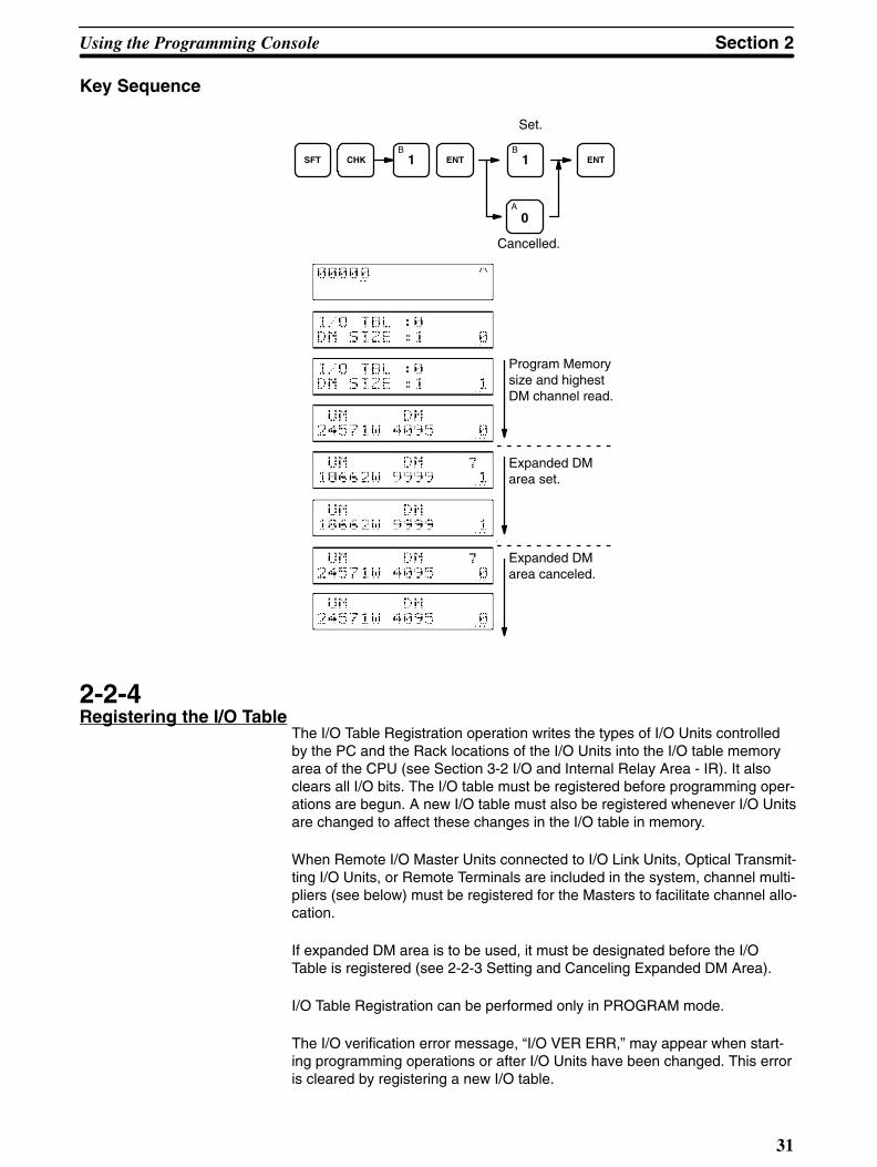
Section 2Using the Programming Console
31
Key Sequence
CHKB
1SFT ENT
A
0
B1
Set.
Cancelled.
ENT
Program Memorysize and highestDM channel read.
Expanded DMarea set.
Expanded DMarea canceled.
2-2-4Registering the I/O Table
The I/O Table Registration operation writes the types of I/O Units controlledby the PC and the Rack locations of the I/O Units into the I/O table memoryarea of the CPU (see Section 3-2 I/O and Internal Relay Area - IR). It alsoclears all I/O bits. The I/O table must be registered before programming oper-ations are begun. A new I/O table must also be registered whenever I/O Unitsare changed to affect these changes in the I/O table in memory.
When Remote I/O Master Units connected to I/O Link Units, Optical Transmit-ting I/O Units, or Remote Terminals are included in the system, channel multi-pliers (see below) must be registered for the Masters to facilitate channel allo-cation.
If expanded DM area is to be used, it must be designated before the I/OTable is registered (see 2-2-3 Setting and Canceling Expanded DM Area).
I/O Table Registration can be performed only in PROGRAM mode.
The I/O verification error message, “I/O VER ERR,” may appear when start-ing programming operations or after I/O Units have been changed. This erroris cleared by registering a new I/O table.

Using the Programming Console Section 2
32
Key Sequence
SFT CHK ENT ENT
9 7B
1D
3 ENTChannel multipliers registerednext, if necessary.
Basic Registration
SHIFT
CHK
ENT
B D79 1 3
ENT
ENT
Registering Channel Mul-tipliers for Masters
When Remote I/O Master Units in the system are connected to I/O Link Units,Optical Transmitting I/O Units, or Remote Terminals, a channel multiplier be-tween 0 and 3 must be assigned to each of the Masters after registering theI/O table. The same channel multiplier can be assigned to more than oneMaster in the same system as long as the same channel is not allocated tomore than one Unit. Channel allocations to I/O Link Units, Optical Transmit-ting I/O Units, and Remote Terminals are computed from the channels set onthe Units and the channel number assigned to the Master controlling the Unitas follows:
(32 x channel multiplier) + (channel setting on the Unit)
Make sure that the lowest channels allocated to I/O Link Units, Optical Trans-mitting I/O Units, or Remote Terminals connected to the Master with the low-est channel multiplier do not overlap with the highest I/O channels on the lastExpansion I/O Rack.

Section 2Using the Programming Console
33
A
0
ENT
ENT
For Remote I/O Units
Automatic I/O channelconfirmation
Appears inabout 2 s.
Input channel multiplier andENT. Display for next Mas-ter appears automatically.
Continue inputting channel multiplierspressing ENT after each.
If asterisk is not displayed, pressENT to leave previously enteredchannel multiplier unchanged, orenter new channel multiplier andthen press ENT.
Appears when all channel mul-tipliers are input/confirmed.
Meaning of Displays
Prompt for channel multiplier
Indicates no channel multiplier has yet been set.
Remote I/O Master No.
Indicates Remote I/O Master.
I/O slot no.
Rack no.
2-2-5Reading Error Messages
After the I/O table has been registered, a check should be made for errors inthe system. Error messages can be displayed by pressing MON, FUN, andthen ENT. This operation can be performed in any mode. If an error messageis displayed, press ENT to clear the error.
Sometimes a beeper will sound and the error cannot be cleared. If this hap-pens, take the appropriate corrective action (see Section 6 Error Messagesand Troubleshooting) to eliminate the error.
When several errors occur, further error messages can be displayed bypressing ENT. The sequence in which error messages are displayed dependson the priority levels of the errors. Some errors are fatal and will cause theCPU to halt; others are non-fatal.
If no errors exist or when all existing errors have been cleared, SYS FAIL OKwill be displayed. Refer to 6-2 Reading Error Messages for actual displays.

Using the Programming Console Section 2
34
Key Sequence
MONTR FUN ENT ENT
2-2-6Verifying the I/O Table
The I/O Table Verification operation is used to check the I/O table registeredin memory to see if it matches the actual sequence of I/O Units mounted onthe Racks. It can be performed in any mode. The first inconsistency discov-ered will be displayed as shown below. Every subsequent pressing of ENTdisplays the next inconsistency.
Key Sequence
SFT
CHK
ENT
C2 ENT
ENT
No discrepancies
Discrepancies
I/O slot no. Rack no.
Actual mount-ing condition
Meaning of Displays
Optical Transmitting I/O Unit No. Error
Remote I/O Error
Same unit no. used twice
This is a Remote I/O Unit thathas not been registered
Indicates too many Slaves in system.

Section 2Using the Programming Console
35
2-2-7Reading the I/O Table
The I/O Table Read operation is used to access the I/O table that is currentlyregistered in the CPU memory. It can be performed in any mode.
Example of I/O UnitMounting
Expansion I/O Racks
Rack 0
0 1 2 3 4 5 6 7
Slot no.
CPU Rack
Rack 1
Rack 2
Rack 3

Using the Programming Console Section 2
36
Key Sequence
SFT CHK ENTB
1 ENT
[0—7] [0—7] ENT
SFT ENT
Rackno.
Slotno.
SHIFT
CHK
ENT
B1
ENT
C
D
2
3
ENT
ENT
+ / –
ENT
SHIFT ENT
SHIFT ENT
+ / –

Section 2Using the Programming Console
37
Meaning of Displays
I/O Unit Designations for Displays
No. of Points Input Unit Output Unit
16
32
64
• I/O Units, Special I/O Units, I/O Link Units
I/O channel no.
I/O Unit type: I (input), O (out-put), or N (reserved)
Slot no.
Rack No.
• Remote I/O Master Units
Channel Multiplier (0 to 3)
Master no. (0 to 7)
Note: The channel multiplier is displayed only when Optical TransmittingI/O Units, I/O Link Units, or Remote Terminals are connected tothe Remote I/O Master Unit.

Using the Programming Console Section 2
38
• Remote I/O Slave Units
I/O channel no.
I/O Unit type: I (input), O (output), or N (reserved)
Slot no.
Remote I/O Slave Unit no. (0 to 7)
Remote I/O Master Unit no. (0 to 7)
Indicates a Remote I/O Unit.
• Interrupt Units
Interrupt Unit no.
• Optical Transmitting I/O Units, I/O LinkUnits, and Remote Terminals
I/O Unit type: I (input), O (out-put), or N (reserved)
Remote I/O Master no. (0 to 7)
Channel (H,L)
I/O Channel no. (0 to 127)
2-2-8Changing the I/O Table
The I/O Table Change operation allows you to register non-existent I/O Unitsin the I/O table. By reserving an entry in the I/O table with this operation, youcan prevent channel number discrepancies when an I/O Unit is to be addedto the system in the future. A non-existent I/O Unit can also be registered toprevent discrepancies after an I/O Unit is removed.
When this operation is performed for the first time, the I/O verification errormessage is displayed because the registered I/O table does not agree withthe actually mounted Units. Disregard this error message. This message willnot be displayed for channel reservations (3, see below).
Register the I/O table (I/O TBL WRIT) before performing the I/O TableChange operation. If you register the I/O table after the I/O Table Change op-eration, the non-existent I/O Unit registrations will be cleared.

Section 2Using the Programming Console
39
Non-existent I/O table entries can be made for Input Units (use the 1 key),Output Units (use the 0 key), and for channels (use the 3 key). Press the keyonce for each Unit or channel, e.g., pressing the 3 key twice before pressingWRITE will reserve two channels.
Note: An Input Unit reservation cannot be used for an Output Unit and viceversa. Also, non-existent I/O Units cannot be registered for Remote I/O Units,Optical Transmitting I/O Units, or Interrupt Units.
Key Sequence
I/O Table Readin progress.
CHGA
0 ENT
D3
B1
O: Output Unit
1: Input Unit
3: Channel
Example
CHG
A
0A
0
ENT
ENT
ENTSHIFT
CHG
B1
ENT
ENTSHIFT
CHG
D3
D3
ENT
Reserving slot for a32-point Output Unit
When I/O Table Is First Changed
When I/O Table Has Been Changed Before
Reading slot withno I/O Unit
Reserving slot for a16-point Input Unit
Reserving 2 channels
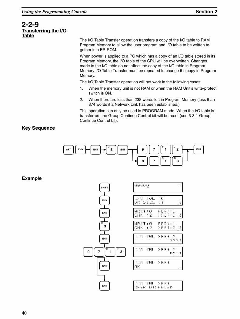
Using the Programming Console Section 2
40
2-2-9Transferring the I/OTable
The I/O Table Transfer operation transfers a copy of the I/O table to RAMProgram Memory to allow the user program and I/O table to be written to-gether into EP-ROM.
When power is applied to a PC which has a copy of an I/O table stored in itsProgram Memory, the I/O table of the CPU will be overwritten. Changesmade in the I/O table do not affect the copy of the I/O table in ProgramMemory I/O Table Transfer must be repeated to change the copy in ProgramMemory.
The I/O Table Transfer operation will not work in the following cases:
1. When the memory unit is not RAM or when the RAM Unit’s write-protectswitch is ON.
2. When there are less than 238 words left in Program Memory (less than374 words if a Network Link has been established.)
This operation can only be used in PROGRAM mode. When the I/O table istransferred, the Group Continue Control bit will be reset (see 3-3-1 GroupContinue Control bit).
Key Sequence
SFT CHK ENTD
3 ENT 9
9
7
7
B1
B1
C2
D3
ENT
Example
CHK
SHIFT
ENT
ENT
ENT
ENT
B D79 1 3
D3

Section 2Using the Programming Console
41
2-3ProgrammingOperations
The Programming Console operations described in this section can generallybe cancelled by pressing CLR.
2-3-1Setting a ProgramAddress
To write, insert, read, or delete program instructions, you must first specify theaddress at which to read or make changes.
Leading 0’s of the address expression need not be keyed in. That is, whenspecifying an address such as 00053 you need to enter 53 only.
After specifying the address, press READ and ENT to display the contents ofthe address.
Key Sequence
CLR [Address]
Example
CLR
EB C D41 2 3
2-3-2Program Write
Programs are written into Program Memory using mnemonic code. The mainline of the program is written in first, followed by any branches and then groupprograms. The main line of a group program is also written in first, follow byany branches in the group program. The operation shown below is also usedin changing or inserting new instructions into programs that already exist.
Programs can be written after the required address has been set. Be sure toclear all data areas and Program Memory if you are writing in a new program,even if the Memory Unit is new. Then press CLR to go to address 00000.
To begin writing, press WRITE, input the instruction along with any data or setvalues required by it, and then press ENT. Continue on by inputting instruc-tions, any data or set values required by them, and then ENT after completingeach instruction.
Most instructions can be input by function number. To do so, press FUN, thetwo-digit function number, and then ENT followed by any data or set valuesrequired by the instruction and then ENT again. See Section 4 ProgrammingInstructions or Appendix C Programming Instructions for specific functionnumbers.
Error DisplaysIf any of the following appear in the upper right corner of the display, an errorhas been made in writing the program. Respond as indicated.

Using the Programming Console Section 2
42
The capacity of Program Memory has been exceeded. Use a largerMemory Unit or reduce the size of the program.
The Memory Unit is ROM and cannot be written into. Use a RAMUnit.
Either the format of an instruction is incorrect or data required forthe instruction was missing when ENT was pressed. Check the for-mat and data requirements in Section 4 Programming Instructions.
The last address in Program Memory has been exceeded. Use alarger Memory Unit or reduce the size of the program.
Display Error and correction
Key Sequence
Address currentlydisplayed.
[Instruction] ENTWRITE
ExampleThe following operation is programmed and converted to mnemonic code,and the operations and displays for writing it into memory are provided.
1. The ON time of a photoelectric switch (input 00002) is measured to de-termine the length of products passing by on a conveyor belt.
2. A solenoid (output 00500) is activated to push all products with an ONtime of less then 2 seconds down chute 1 and a sensor (input 00003) atthe bottom of the chute confirms that the product has passed.
3. Another solenoid (output 00501) is activated to push all products with anON time of 2 seconds or greater down chute 2 and a sensor (input00004) at the bottom of the chute confirms that the product has passed.

Section 2Using the Programming Console
43
Program Mnemonic Code
Yes
No
Yes
No
LBL 0000
LD 00002
WAIT
TIM 000
#0100
CJP LBL 0001
LBL 0001
AND NOT 00002
WAIT
CMP(52)
TIM000
#0080
AND 25507
CJP LBL 0002
OUT 00500
LBL 0003
OR 00003
OR 00004
WAIT
OUT NOT 00500
OUT NOT 00501
CNR TIM000
JMP LBL0000
LBL 0002
OUT 00501
JMP LBL0003
(SW 1 ON)
(SW 1 OFF)
(10-s timer)
Timer’s current valuecompared to 8 “seconds.”
Less Than flag (ON if timerruns longer than 2 seconds.)
Outputs
Productconfirmed.
Outputs andtimer reset.
Address Instruction Data
00000 LBL 0000
00001 LD 00002
00002 WAIT ---
00003 TIM 000
# 0100
00004 CJP LBL 0001
00005 LBL 0001
00006 AND NOT 00002
00007 WAIT ---
00008 CMP(52) ---
TIM 000
# 0080
00009 AND 25507
00010 CJP LBL 0002
00011 OUT 00500
00012 LBL 0003
00013 OR 00003
00014 OR 00004
00015 WAIT ---
00016 OUT NOT 00500
00017 OUT NOT 00501
00018 CNR TIM 000
00019 JMP LBL 0000
00020 LBL 0002
00021 OUT 00501
00022 JMP LBL 0003
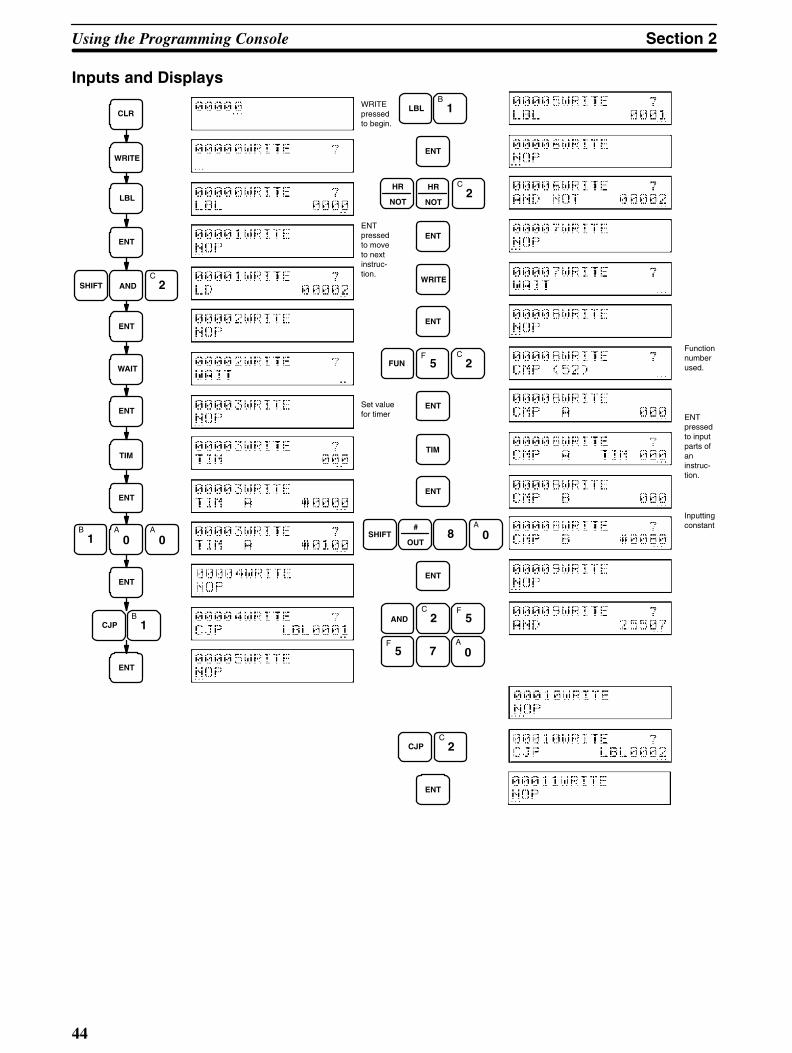
Using the Programming Console Section 2
44
Inputs and Displays
WRITEpressedto begin.
ENTpressedto moveto next instruc-tion.
Set valuefor timer
CLR
WRITE
LBL
ENT
SHIFT ANDC
2
WAIT
ENT
ENT
TIM
ENT
B A1 0
A
0
CJPB
1
ENT
ENT
#
OUTSHIFT 8
A
0
LBLB
1
ENT
ENT
HR
NOT
HR
NOT
C2
FUNF
5C
2
ENT
WRITE
ENT
ENT
TIM
ENT
ENT
7
F5AND
C2
A
0F
5
C2CJP
Functionnumberused.
ENTpressedto inputparts ofan instruc-tion.
Inputtingconstant

Section 2Using the Programming Console
45
#
OUT
F A5 0
A
0
LBL
ENT
D3
ENT
ENT
ENT
D3
ORE
4
OR
WAIT
ENT
#
OUT
HR
NOT
F5
A
0A
0
ENT
CNR TIM
ENT
#
OUT
HR
NOT
F5
A
0
ENT
B1
LBLC
2
ENT
D3JMP
#
OUT
F5
A
0B
1
JMP
ENT
ENT
ENT
Programming YESbranch from CJP.

Using the Programming Console Section 2
46
2-3-3Program Read
To read out program data from the Program Memory, specify the addressfrom which to read, then press READ and ENT.
After a display has appeared for the specified address, ENT is then pressedto display either the next display for the same address (if more than one dis-play is required to show all input data) or a display for the next address.
The “+” in the upper right corner of the display indicates that addresses willbe incremented as ENT is pressed. If the +/– key is pressed, the “+” willchange to “–” and addresses will be decremented as ENT is pressed. The +/–key can be pressed whenever desired during readout to change the directionaddresses will change.
If ENT is held down, addresses will change at high speed.
This operation can be performed in any mode, and address can be monitoredif it is used in RUN or MONITOR mode. It can also be used to change setvalues for timers and counters during program execution (see below).
Error DisplaysIf an O is displayed in the upper right corner, the address range has been ex-ceeded; press CLR and repeat the Program Read operation from the desiredaddress.
Key Sequence
Address currentlydisplayed.
READ ENT
+ / –

Section 2Using the Programming Console
47
ExampleReading part of the program example used in 2-3-2 Program Write would re-sult in the following displays.
CLR
8
READ
ENT
ENT
ENT
ENT
ENT
ENT
+ / –
+ / –
ENT
Change to addressdecrementing
Change to addressincrementing
Timer/Counter SVChanges
When a timer or counter is displayed during Program Read, CHG can bepressed to change the set value of the timer or counter. This is possible onlywhile the program is being executed in MONITOR or in the Debug operationunder PROGRAM mode. If the program is not being executed, change setvalues in PROGRAM mode (but not in the Debug operation) using the Pro-gram Write operation.
To change the set value, read the desired timer or counter, press CHG, inputthe new set value, and press ENT. Once a set value has been changed, Pro-gram Read can be continued as normal.

Using the Programming Console Section 2
48
2-3-4Instruction Search
To search for specific instructions in Program Memory, first either set the ad-dress (see 2-3-1 Setting a Program Address) or read through the program(see 2-3-3 Program Read) to the address from which the instruction is to besearched for. Then, specify the instruction you wish to search for and pressSRCH. To continue searching for the same instruction in the remainder of theprogram, press ENT. Any further occurrences of the instruction will be dis-played until the last Program Memory address is encountered.
To access operands for any instructions requiring more than one display,press READ and then ENT.
This operation can be performed in any mode.
Error DisplaysIf a O is displayed in the upper right corner during a search operation, the lastaddress has been exceeded. If an N is displayed, the instruction that wassearched for does not exist from the starting point to the end of ProgramMemory.
Key Sequence
Address currentlydisplayed.
[Instruction] ENTSRCH
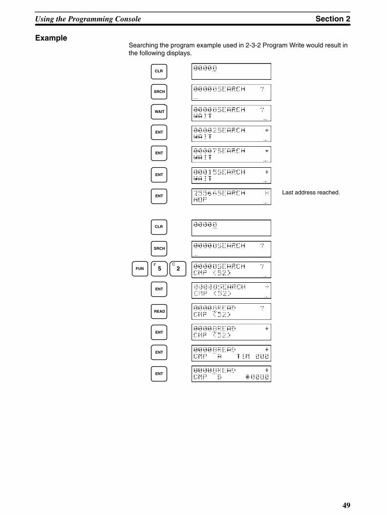
Section 2Using the Programming Console
49
ExampleSearching the program example used in 2-3-2 Program Write would result inthe following displays.
Last address reached.
CLR
SRCH
WAIT
ENT
ENT
ENT
ENT
CLR
SRCH
FUNF
5C
2
ENT
READ
ENT
ENT
ENT

Using the Programming Console Section 2
50
2-3-5Instruction Insert
This operation is used to change a program by inserting an instruction. Insert-ing an instruction will increase the address for all following instructions byone.
To insert, read the address before which the instruction is to be inserted,press INS, and then write in the instruction in the same manner as when writ-ing a program (see 2-3-2 Program Write). More than one instruction can beinserted at once.
Instructions cannot be inserted into a program during RUN or MONITORmode or during the Debug operation. They cannot be inserted if there is notenough space remaining in Program Memory to hold them.
After inserting one or more instructions, it is best to check the inserted in-structions and then perform a Program Check.
Error DisplaysIf a P is displayed in the upper right corner during a insert operation, there isnot enough room left in Program Memory for the instruction to be inserted. Ifan O is displayed, the last address has been exceeded. If an R is displayed,the program is in ROM and cannot be changed.
Key Sequence
Addressread
[Program Writeoperation]
ENTINS
Example
Address Instruction Data
00000 LBL 0000
00001 LD 00002
00002 AND 00005
00003 WAIT --
00004 TIM 000
# 0100
Address Instruction Data
00000 LBL 0000
00001 LD 00002
00003 WAIT --
00004 TIM 000
# 0100
Inserted.
Before Insertion After Insertion
LBL 0000
LD 00002
WAIT
TIM 000
#0100
AND 00005
Inserted here.

Section 2Using the Programming Console
51
Example Continued
CLR
C2
READ
ENT
INS
ANDF
5
ENT
Reading the address before whichinstruction is to be inserted
INS followed by ProgramWrite operation
2-3-6Instruction Delete
This operation is used to change a program by deleting an instruction. In-structions can be deleted only in PROGRAM mode.
When you delete an instruction, you must first read it. The actual deletion isaccomplished by pressing DEL and then ENT. Further instructions can bedeleted as they appear by again pressing ENT. If DEL is pressed at any butthe first address of an instruction that requires more than one address, thedisplay with return to the first address for that instruction and await input ofENT.
The program addresses following the deleted instruction are automaticallydecremented according to the number of instructions deleted.
Be careful not to inadvertently delete instructions.
Error DisplaysIf an R is displayed, the program is in ROM and cannot be changed. If an O isdisplayed, the last address has been exceeded.
Key Sequence
Address currentlyread. DEL ENT

Using the Programming Console Section 2
52
ExampleThe operation and displays for deleting the indicated instruction in the exam-ple flowchart are provided along with the mnemonic code for the flowchart.
Before Deletion
Address Instruction Data
00000 LBL 0000
00001 LD 00002
00003 WAIT --
00004 TIM 000
# 0100
Address Instruction Data
00000 LBL 0000
00001 LD 00002
00002 AND 00005
00003 WAIT --
00004 TIM 000
# 0100
LBL 0000
LD 00002
AND 00005
WAIT
TIM 000
#0100Before Deletion After Deletion
CLR
ENT
C2
READ
DEL
ENT
2-3-7Program Check
This operation does a syntax check on a program. When a program has beenchanged in any way, it should first be checked for programming errors beforeexecution. A program can be checked only in PROGRAM mode.
If there are no errors in the program, “OK” will be displayed. If an error is dis-covered, the display will stop at the address that generates the error and indi-cate the nature of the error (see table below). The entire program can then bechecked by pressing ENT for every error display until the end of the programis reached, at which time “END” will be displayed. The display will indicate the
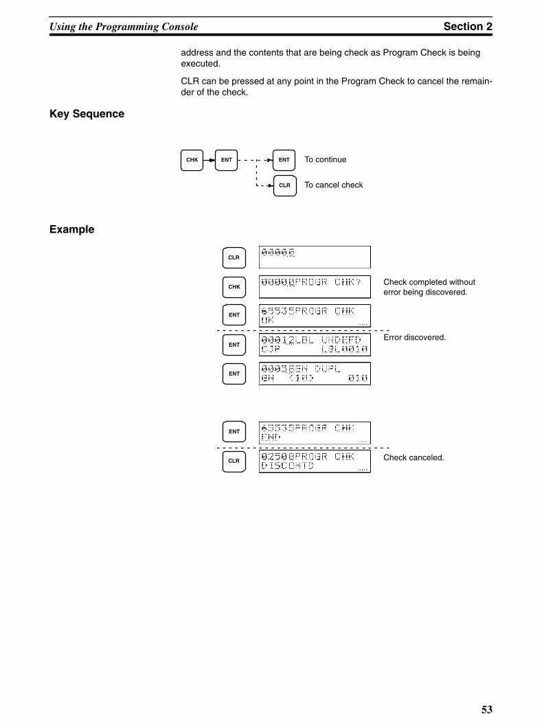
Section 2Using the Programming Console
53
address and the contents that are being check as Program Check is beingexecuted.
CLR can be pressed at any point in the Program Check to cancel the remain-der of the check.
Key Sequence
CHK ENT ENT
CLR
To continue
To cancel check
Example
CLR
Check completed withouterror being discovered.
Error discovered.
Check canceled.
CHK
ENT
ENT
ENT
ENT
CLR
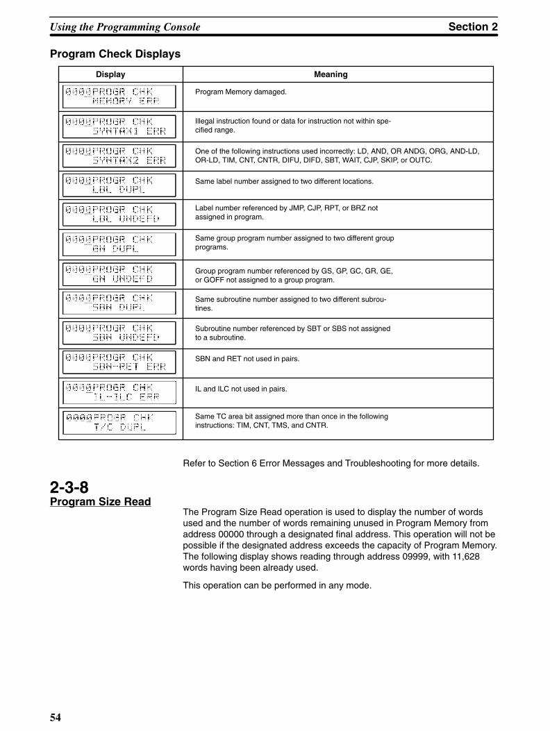
Using the Programming Console Section 2
54
Program Check Displays
Display Meaning
Program Memory damaged.
Illegal instruction found or data for instruction not within spe-cified range.
One of the following instructions used incorrectly: LD, AND, OR ANDG, ORG, AND-LD,OR-LD, TIM, CNT, CNTR, DIFU, DIFD, SBT, WAIT, CJP, SKIP, or OUTC.
Same label number assigned to two different locations.
Label number referenced by JMP, CJP, RPT, or BRZ notassigned in program.
Same group program number assigned to two different groupprograms.
Group program number referenced by GS, GP, GC, GR, GE,or GOFF not assigned to a group program.
Same subroutine number assigned to two different subrou-tines.
Subroutine number referenced by SBT or SBS not assignedto a subroutine.
SBN and RET not used in pairs.
IL and ILC not used in pairs.
Same TC area bit assigned more than once in the followinginstructions: TIM, CNT, TMS, and CNTR.
Refer to Section 6 Error Messages and Troubleshooting for more details.
2-3-8Program Size Read
The Program Size Read operation is used to display the number of wordsused and the number of words remaining unused in Program Memory fromaddress 00000 through a designated final address. This operation will not bepossible if the designated address exceeds the capacity of Program Memory.The following display shows reading through address 09999, with 11,628words having been already used.
This operation can be performed in any mode.

Section 2Using the Programming Console
55
Key Sequence
Final addressdesignated.
SHIFT READ ENT
CLR
9 9 9 9
SHIFT READ
ENT
No. of words remaining unused
2-4Monitor and DataChange Operations
The Monitor and Data Change operations allow you to monitor the status ofbits, channels, or timers/counters during program execution while also moni-toring the status of program execution itself. While monitoring channels/bits,present values for timers/counters and other channels can be modified andoutput status can be controlled.
Address MonitoringThe simplest form of monitoring is to perform the Program Read operation(see 2-3-3 Program Read) while running the PC program. The status of eachaddress will be displayed along with the contents of the address. To monitoraddresses, set the Programming Console to either RUN or MONITOR mode,press ENT, and preform the Program Read operation while executing the PCprogram. The key sequence and status displays are as follows:
Key Sequence
Address currentlydisplayed.
READ ENT
+ / –

Using the Programming Console Section 2
56
I/O Displays ON or OFF status of I/O point
Timers and CountersTime or count expiredPresent value
Channel Data
Data in channel
Group InstructionsGroup program statusACT: on standbyEXE: being executed
Execution Address Monitor
Addresses can also be monitored with the Execution Address Monitor opera-tion, which not only allows addresses and associated status to be monitored,but also enables automatic monitoring of the address that is being executedso that you can follow program execution as it occurs. This operation is possi-ble only in RUN and PROGRAM modes, and only while the program is beingexecuted.
After pressing SHIFT and then MONITOR, ENT can be pressed to control theaddress being displayed or SHIFT and then ENT can be pressed to automati-cally follow the address that is being executed. If ENT is pressed withoutshift, HR/NOT can be pressed to switch back and forth between normal dis-plays and displays of the contents of any “S” messages inserted into the pro-gram using S (see 4-14-1 Process Display - S(47)). Any S numbers insertedinto the program will be displayed and will not change until another S numberoccurs in the program.
Any time after the Execution Address Monitor operation has been entered,ENT can be pressed to gain control of the address being displayed, or SHIFTand then ENT can be pressed to activate automatic display of the addressbeing executed.

Section 2Using the Programming Console
57
• Key Sequence
SHIFT MONTR
SHIFT ENT
ENTDesignated addressdisplayed.
Currently executedaddress displayed.
HR
NOT
CLR
SHIFT
MONTR
ENT
ENT
HR
NOT
HR
NOT
ENTSHIFT
ENT
S message
Displays automaticallychange according toexecution status.
• Meaning of DisplaysNormal displays show the address, any S number that has been defined, andthe status of the operand of the instruction. If the operand is a bit, the statusshows whether the bit is ON or OFF; if it is a timer/counter or channel, thepresent value of the timer/counter or channel; and if it is a group program, thecurrent execution status of the group program. S message displays show theaddress, S number and contents of the “S” message.
Address S no. Status Address S no.
Normal Displays S Messages
Data Area MonitorThis operation is used as the starting point for all operations described in fol-lowing subsections. It is used to monitor the status of any point or channel inthe IR, AR, HR, SR, LR, TC, or DM area. This operation can be used in anymode (although some operations entered though it cannot).

Using the Programming Console Section 2
58
To monitor a bit in the IR or AR area, designate the instruction used with thepoint (e.g., AND, OR, OUT), input the bit number, and press ENT. To monitora timer or counter, input either TIM or CNT, the timer/counter number, andENT. To monitor any other channel, input */CH, the data area designation keyfor any other than an IR or AR channel, the channel number, and ENT.
Up to three channels/bits can be monitored simultaneously. To monitor anoth-er channel/bit, move the cursor to the left with the arrow key and repeat theabove operation for the desired channel/bit. The arrow key can then be usedagain to designate a third channel/bit, or to return to a previously designatedchannel/bit to designate a new channel/bit or to designated a displayed chan-nel/bit for use in one of the functions described in following subsections.
Once a channel or bit has been displayed ENT and the +/– key can bepressed to display the channel/bit one higher or lower than the one currentlyindicated by the cursor just as in Program Read (see 2-3-3 Program Read).
• Key Sequence
MONTR [Bit no.]
[Bit in-struction]
[*/CH and data areakey if required.]
TIMor CNT
[Channelno.]
[Timer/counterno.]
ENT
+ / –
ENT
MONTR
AND
ENT
BD A13 0
B1
SHIFTHR
NOT*
CH
B1
A
0
ENT
Monitorsinput03101
Cursorreturn
MonitorschannelHR 10

Section 2Using the Programming Console
59
• Meaning of DisplaysData areas are indicated in the displays with the following letters.
No letter
c
H
cH
A
cA
L
cL
T
C
D
IR or SR area bit
IR or SR area channel
HR area bit
HR area channel
AR area bit
AR area channel
LR area bit
LR area channel
Timer number (small box in lower left corner: time expired)
Counter number
DM area channel
• HEX-ASCII DisplaysChannel displays of hexadecimal data can be changed to ASCII-code dis-plays by pressing HR/NOT. The data for all channels displayed will bechanged. NR/NOT can then be pressed again to return the display to hexade-cimal data.
When using this function with Channel Value Changes (see 2-4-2 ChannelData Changes), data can be changed while displayed in ASCII, but all datainputs must be in hexadecimal.
2-4-1Force Set/Reset
Whenever the cursor is positioned at an IR, HR, AR, or LR bit under the DataArea Monitor operation, SET or RESET can be pressed to force-set or force-reset the bit. It can also be used to force set/reset timers and counters.Force-setting and force-resetting is not possible in RUN mode.
When timers or counters are set, the present value goes to zero and the TCbit assigned for it goes ON. When timers or counters are reset, the presentvalue goes to the set value (counters to zero) and the assigned bit goes OFF.
Key Sequence
[Data Area Monitor] SET
RESET
ENT
2-4-2Channel Data Changes
Any decimal or hexadecimal value of a channel in the IR, LR, HR, AR, TC, orDM area can be changed when displayed under Data Area Monitor. This ispossible only in MONITOR mode or in the Debug operation under PRO-GRAM mode. The present value of timers and counters may be changedwhile the timer/counter is operating.

Using the Programming Console Section 2
60
To change channel data, position the cursor at the desired channel or timer/counter, press CHG, enter the new value, and press ENT. Normal Data AreaMonitor operations are then returned to.
This operation cannot be used to change the set value of a timer or counter.Set values are changed either using Program Read when the program is be-ing executed or using Program Write when the program is not being executed(see 2-3-3 Program Read for details).
Key Sequence
[Data Area Monitor] CHK [New value ] ENT
Example
[Data Area Monitor]
CHG
ENT
C A2 0
A
0
2-4-3Single ChannelOperations in Binary
A channel being displayed under Data Area Monitor can be displayed andchanged in binary, i.e., each bit of a channel can be displayed/controlled indi-vidually.
Binary MonitorTo display a channel in binary, position the cursor under the desired channeland press SHIFT and then ENT. The channels before and after the displayedchannel can be moved to by using ENT and the +/– key to increment anddecrement the display channel number, just as in Program Read (see 2-3-3Program Read).
At any point in a binary display, SHIFT and then ENT can be pressed to re-turn to a normal channel display.
Binary displays are possible in any mode.
Key Sequence
SHIFT ENT[Data Area Monitor] EXT
+ / –

Section 2Using the Programming Console
61
Example
[Data Area Monitor]
SHIFT ENT
+ / –
SHIFT ENT
ENT
ENT
Binary ChangeChannels, except for those in the SR area, displayed in binary can bechanged bit by bit in any but RUN mode.
To change a bit value, position the cursor under the desired bit and press ei-ther the 1 or 0 key. To move the cursor to the left, press the arrow key. Thecursor will automatically move to the right when the 1 or 0 key is input. Aftercompleting all changes to the channel, press ENT to return to the binary mon-itor display.
Key Sequence
[Binary Monitor CHGA
0
B1
ENT

Using the Programming Console Section 2
62
Example
[Binary Monitor]
CHG
ENT
B
A
1
0
2-4-4Three-ChannelOperations
Any three consecutive channels or group programs can be monitored orchanged together by entering the Data Area Monitor operation and using thefollowing procedures.
Three-Channel MonitorTo monitor three consecutive channels/group programs together, position thecursor under the lowest numbered channel/group program, press EXT, andthen press ENT to display the status of the specified channel/group programsand the two channels/group programs that follow it.
If group program status is displayed, SHIFT and then ENT may be pressed todisplay the S numbers for the three groups. These key inputs are then re-peated to return to status displays.
To return to the original display using the leftmost channel/group program cur-rently displayed, press CLR.
Once three channels/group programs have been displayed, ENT and the +/–key can be pressed to shift the displayed channels/group program one higheror lower than the ones currently displayed, similar to the use of these keys inProgram Read (see 2-3-3 Program Read). Whenever a channel/group pro-gram is thus shifted onto the display, the channel/group program at the oppo-site end of the display will be shifted off the display.
This operation is possible in any mode.

Section 2Using the Programming Console
63
Key Sequence
[Data Area Monitor] EXT + / – ENT
SFT ENT(Group programmonitoring)
Example
[Data Area Monitor]
EXT
CLR
ENT
+ / –
ENT
ENT
Three-Channel ChangeAny of the three channels displayed for Three-Channel Monitor can bechanged by pressing CHG, positioning the cursor under the desired channeldata using the arrow key, inputting the new value, and pressing ENT. Morethan one channel can be changed before pressing ENT.
This operation cannot be used to change data if an SR channel is displayed.Change operations are not possible for group programs, nor are they possi-ble in RUN mode.
If CLR is pressed before WRITE, the change operation will be cancelled andthe Three-Channel Monitor operation will resume.
Key Sequence
[Three-Channel Monitor] CHG New value ENT

Using the Programming Console Section 2
64
Example
[Three-Channel Monitor]
CHG
CLR
ENT
E F
B
C D4 5
1
2 3
2-4-5Group Monitor
With the Group Monitor operations, the status of up to three group programs,or the main program and up to two group programs, can be monitored at thesame time. Interrupt or scheduled interrupt programs may also be displayed.Group number 128 is used to designate the main program; 129, to designateinterrupt programs; and 130, to designate scheduled interrupt programs.Group Monitor can be entered either from the Data Area Monitor operation ordirectly from a cleared display (“00000”).
To enter Group Monitor from a cleared display, press MONTR, FUN, the 1key, and then ENT. The display will show the status of a currently activatedgroup.
To enter Group Monitor from Data Area Monitor, press FUN, input the numberof the desired group, and then press ENT.
The operation after displaying the first group program status is the same re-gardless of how Group Monitor is entered. Another group program can bedesignated by moving the cursor to the left with the arrow key and inputtingFUN, the group number, and ENT. This process can then be repeated for athird group.
Once three group programs have been displayed, ENT and the +/– key canbe pressed to shift the displayed group programs one higher or lower thanthe ones currently displayed, similar to the use of these keys in ProgramRead (see 2-3-3 Program Read). Whenever a group program is thus shiftedonto the display, the group program at the opposite end of the display will beshifted off the display.
Group Monitor is not possible in PROGRAM mode.

Section 2Using the Programming Console
65
Meaning of DisplaysThe status, group number, and address currently being executed in the groupprogram are displayed as shown below. Symbols (other than actual groupnumbers) used in the display are as follows:
Status Group Numbers
e Being executed M Main program
a Awaiting execution Ixx Interrupt programs (xx is interrupt no.)
= Pause IT Scheduled interrupt program
– Ended
If an interrupt program is being executed, its number will be displayed.
Status
Currently executedaddress
Group no.
S Number and MessageDisplays
If SHIFT and then ENT are pressed from a Group Monitor display, and Snumbers designated with the S instruction will be displayed when the S in-struction is executed. Once an S number has been displayed, it will remainuntil another S instruction is executed. “S––––” will be displayed if no S in-struction has yet been executed. SHIFT and then ENT can be pressed againto return to the normal Group Monitor display. (See 4-14-1 Process Displayfor details on S numbers and S messages.)
If HR/NOT is pressed during an S number display, the S message for thatnumber will be displayed. If no S instruction has been executed in the group,“S––––” will be displayed. HR/NOT can be pressed again to return to the nor-mal S number display.
Key Sequence
Address currently read. ENTDEL

Using the Programming Console Section 2
66
Example
DEL
READ
CLR
ENT
C2
ENT
2-5Debugging
Debugging is the program development step during which a programmerfinds and fixes errors in the program. Debugging can require extensive time,especially if the program being debugged is complex. The debugging opera-tions presented in following subsections help to make debugging less time-consuming.
The Debug operation is entered from PROGRAM mode to access specialdebugging operations. There are basically three different operations avail-able. The first operation, Step Execution, enables step-by-step program ex-ecution. It also provides control of branching, skipping, and waiting in the pro-gram to enable execution of desired program sections regardless of input sta-tus. The second operation, Section Execution, allows for a program sectionbetween designated starting and ending addresses to be executed. This op-eration is usually applied to a program only after it has been subjected toStep Execution. The third operation, Program Tracing, allows 250 steps of aprogram to be executed and the results stored in Trace Memory.
Except for the third operation, Program Trace, these debugging operationsare available only after the Debug operation has been entered from PRO-GRAM mode.
Entering the DebugOperation
The PC must be in PROGRAM mode to enter the Debug operation. Althoughthe Clear Memory, Program Write, Instruction Insert, and Instruction Deleteoperations are not possible under the Debug operation, all other PROGRAMmode operations are available.
To enter the Debug operation, press SHIFT, the 0 or the 1 key (0 is the de-fault), CHG, and ENT. If the 0 key is pressed, program jumps to group pro-grams, between group programs, or from group programs to the main pro-gram will not be made during execution regardless of program status. If the 1key is pressed, the program will jump as written.
To leave the debug operation, press SHIFT and then CHG.
When Debug mode is entered or left, data in the IR, AR, and LR areas iscleared unless the Data Retention control bit is ON (see 3-3-2 Data RetentionControl Bit).

Section 2Using the Programming Console
67
Key Sequence
Entering Debug Operation
SHIFT CHKA
0 ENT
B1
No group jumps
Jumps as written
Leaving Debug Operation
SHIFT CHK ENT
CHGSHIFT
CLR
ENTA
0
ENT
CHGSHIFT
2-5-1Step Execution
Step Execution is used to execute a program step by step. After pressingSHIFT, SET, the starting address, and ENT, one step of the program will beexecuted each time ENT is pressed thereafter. If the desired starting addressis already displayed, only ENT is necessary.
All I/O points will be active during Step Execution. Outputs can be preventedby turning ON the Output OFF bit (25215). Execution may be held up atWAIT, CJP, or SKIP if required conditions are not present to continue execu-tion. Conditions for these can be controlled(see Forced Condition Execution,below).
Execution of FALS will cancel Step Execution.
Program Read, Instruction Search, and monitor operations are possible dur-ing Step Execution. After any of these operations have been performed, StepExecution can be resumed by pressing CLR.

Using the Programming Console Section 2
68
Key Sequence
SHIFT SET [Start address] ENT ENT ENT
Step execution
SHIFT SET
ENT
B C D1 2 3
ENT
ENT
ENT
Forced Condition Execution
Conditions determining execution routes from WAIT, CJP, and SKIP (or any ofthese with NOT) can be controlled during Step Execution. To designate thenext step after any of these instructions, input SET or RESET instead of ENTwhen the instruction is displayed.
SET (YES) for WAIT will move execution to the step following WAIT; for CJP,to the jump destination label designated by CJP; and for SKIP, to the instruc-tion designated to be skipped to.
RESET (NO) for WAIT will move execution to the beginning of the conditionline or block for WAIT; for CJP or SKIP, to the next instruction following CJPor SKIP.
Key Sequence
[Step Execution]
SET
RESET
ENT

Section 2Using the Programming Console
69
2-5-2Section Execution
Once a program has been checked for proper execution with Step Execution,I/O points should actually be wired and the program should be executed totest-operate the controlled system using Section Execution.
Section Execution lets you run a program between a designated starting ad-dress and a designated stopping address. Press SHIFT and the SET underthe Debug operation, designate the starting and stopping addresses if differ-ent from the displayed address pressing ENT after each, and then pressSHIFT and ENT to activate program execution. The address being executedwill be automatically displayed.
ENT can be pressed during program execution to cancel Section Execution.The address displayed after ENT is pressed is not executed. ENT can thenbe pressed to continue program execution using Step Execution.
After execution has completed, press CLR. Step Execution will be switchedto.
Program execution can get caught in loops if required inputs are not presentfor WAIT or CJP. Either wire the system to ensure all required inputs arepresent or use forced condition operation under Step Execution (see 2-5-1Step Execution).

Using the Programming Console Section 2
70
Key Sequence
SHIFT SET [Startingaddress]
ENTStoppingaddress]
ENT SHIFT ENT[
When execution completed to stopping address
Return to Step Execution at completion
Return to Step Execution midway
SHIFT SET
ENT
E F
B C D
4 5 6
1 2 3
ENT
ENTSHIFT
Other Operations duringSection Execution
Data Area Monitor, Group Monitor, Execution Address Monitor, Step Trace,Channel Data Change, Program Read, and Instruction Search operations canbe entered from Section Execution by pressing MONTR, READ, or SRCHduring Section Execution and then proceeding as normal for these opera-tions. If Program Read is entered, set values for timers and counters can alsobe changed (see 2-3-3 Program Read).
To designate the address from which to start a search, move the cursor to theaddress part of the display after pressing SRCH, designate the starting ad-dress, and press ENT to begin the search.
To return to Section Execution after any of the above operations has beenperformed, press CLR. The address currently being executed will be dis-

Section 2Using the Programming Console
71
played, or if Section Execution has been completed, Step Execution for thestopping address will be displayed.
2-5-3Step Trace
The Step Trace operation is used to execute a section of 250 instructionsteps and store the results in Trace Memory (see 4-15 Trace Operations).Step Trace will not be executed if 250 steps are not available for execution,as can happen if the stopping address is reached when Step Trace is ex-ecuted during Section Execution.
To run a Step Trace operation, press MONTR and LBL, input CHG and a trig-ger address or input a label number, and input a delay value and ENT. Thedelay value, which can be any integer from –249 to +250, indicates wheretracing is to begin relative to the trigger address or label. Use the +/– key tochange between positive and negative delays. If the trigger address is 01000and the delay value is –211, the trace area will range from 00789 (01000 –211) to 01038 (00789 + 250).
Step Trace can be canceled during execution by pressing CLR and then ENT.Other operations can also be performed during Step Trace by pressing CLRtwice, which will clear the display, but not cancel Step Trace execution.

Using the Programming Console Section 2
72
Key Sequence
MONTR LBL CHG[Trigger addressor label]
ENT + / – [Delay] ENT
[Label no.]
ReadingTraceMemory(see below)
MONTR
CHG
CLR
ENT
LBL
BC
A
12
0
B1
C2
B1
A
0
ENT
ENT
ENT
ENT
Reading Trace MemoryThe contents of Trace Memory can be read immediately upon execution ofStep Trace by pressing ENT and/or the +/– key, just as in Program Read (see2-3-3 Program Read). It can also be read by clearing the display to 00000,then pressing MONTR, FUN, the 2 key, and ENT, and then pressing ENTand/or the +/– key to control the display.
Reading Trace Memory is not possible until “TRIG OK” is displayed, indicat-ing that the trace has been completed.

Section 2Using the Programming Console
73
Key Sequence
MONTR FUNC
2 ENT
+ / –[Step Trace]
Meaning of Display Address
Number of addresses from trigger
2-6File Memory Operations
When a File Memory Unit is connected to the PC, contents of the ProgramMemory and data areas can be transferred to and from the File Memory(FM).
The FM area can thus be used for auxiliary Program Memory (UM) and DataMemory (IOM) storage, as well as for Comment Memory storage (CM) forflowchart program comments.
Except where specifically noted, these operations are available only in MONI-TOR and PROGRAM modes.
The Programming Console operations described in this subsection can becancelled by pressing CLR during or after the normal key sequence.
2-6-1File Memory Clear
This operation clears the FM. Clearing the entire FM initializes it and pre-pares it for future data storage. This must be done when using a FM Unit forthe first time or when an FM error occurs because of memory damage.
To clear a portion of the FM, you must specify a starting block number and anending block number.

Using the Programming Console Section 2
74
Key Sequence
CLR SHIFT EXT ENT
B1 ENT 9 7
B1
D3
ENT[Startingblock]
ENT[Endingblock]
ENT Total clear
Partial clear
SHIFT
EXT
ENT
B A1 0
ENT
ENT
ENT
ENT
A9 0
A
0
B1
B D79 1 3
ENT
CLR
Partial clear
Total clear
Canceled with CLR
2-6-2File Memory Write
The File Memory Write operation writes data to the FM area. Data either fromProgram Memory or a data area can be transferred to the FM area with thisoperation. Data is written in blocks of 128 words or channels.
When transferring from Program Memory, data between the specified startingaddress and the ending address is moved into the FM area starting at the FM

Section 2Using the Programming Console
75
starting block. If the size of the program data exceeds the space between theFM start block and the end of the FM area, only that part of the program datawhich will fit into the FM area will be transferred and a display will indicatethat transfer was disabled. The block containing the last address transferredwill be registered as the end block for use in reading and verifying FM (seenext two subsections).
When transferring from a data area, data between the specified starting chan-nel and the last channel in the data area designated for transfer will be trans-ferred. For data transfer from the DM area, you must also specify the numberof blocks to be transferred.
Key Sequence
CLR SHIFT EXTB
1 ENTB
1 ENT
SHIFT
SHIFT
SHIFT
TIM
CNT
CNR
HR
NOT
LR
DM
LR
DM
[Starting DMchannel]
ENT[No. ofblocks]
ENT [Startingblock]
ENT
[Startingchannel]
ENT*CH
ENT ENT [Startingaddress]
ENT [Endingaddress]
ENT [Startingblock]
ENT

Using the Programming Console Section 2
76
Example
Transferringto FM
Endblock
Program Memory
Data Area
EXT
SHIFT
LR
DM
ENT
E
B
C D
A
4
1
2 3
0
B1
ENT
ENT
B1
ENT
C2
B1
ENT
B1
A
0A
0
ENT
D3
A
0A
0
ENT
ENT
ENT
8A
0A
0
ENT
FC52
ENT
2-6-3File Memory Verify
The File Memory Verify operation compares data either in Program Memoryor a data area with data stored in the FM area. If the two sets of data differ, a“VER ERR” message will be displayed on the Programming Console.
When data in Program Memory is being verified, this operation comparesProgram Memory data starting at the specified address with FM data be-tween the specified starting block and the ending block registered when datawas transferred to FM (see 2-6-2 File Memory Write).
When data in a data area is being verified, this operation compares data be-tween the specified starting channel and the last channel in the designateddata area to FM data beginning at the designated starting block. For DM areaverification, you must specify the number of blocks to be verified (one blockconsists of 128 channels).

Section 2Using the Programming Console
77
Key Sequence
CLR SHIFT EXTB
1 ENTB
1 ENT
SHIFT
SHIFT
SHIFT
TIM
CNT
CNR
HR
NOT
LR
DM
LR
DMENT ENT ENT
ENT*CH
ENT ENT ENT ENT
[Starting DMchannel]
[No. ofblocks]
[Startingblock]
[Startingchannel]
[Startingaddress]
[Startingblock]
ENTC
2
C2

Using the Programming Console Section 2
78
Example
EXT
SHIFT
LR
DM
ENT
E
B
C
D
A
4
1
2
3
0
B1
ENT
ENT
C2
B1
ENT
C2
B1
ENT
B1
A
0A
0
ENT
ENT
C2
ENT
A
0D
3B
1
ENT
A
0B
1
ENT
Discrepancydiscovered
Non-agreeingblock
Program Memory
Data Area
2-6-4File Memory Read
The File Memory Read operation is used to read program data (UM) stored inthe FM area and transfer it to a specified area in RAM Program Memory, or toread user data (IOM) in the FM area and transfer it to one of the PC dataareas. The data is read and transferred in blocks of 128 words or channels.FM data cannot be read in any mode other than PROGRAM mode and can-not be read under the Debug operation in PROGRAM mode.
When reading data for Program Memory, reading begins at the specified FMstart block. Reading and block transfer ends when either the first end block

Section 2Using the Programming Console
79
(registered when data is transferred to FM) or non-UM (i.e., CM or IOM) FMblock is encountered, or when the RAM Program Memory area to which thedata is being transferred overflows.
When reading data for a data area, reading begins at the specified FM start-ing block and continues to the end. If a non-IOM block is encountered, anerror message will be displayed and transfer will not be possible. When tran-sferring data to the DM area, you must specify the number of blocks to beread and transferred.
Key Sequence
[Starting DMchannel]
[Startingblock]
[No. ofblocks]
ENT
CLR SHIFT EXTB
1 ENTB
1 ENT
SHIFT
SHIFT
SHIFT
TIM
CNT
CNR
HR
NOT
LR
DM
LR
DMENT ENT
ENT*CH
ENT ENT ENT ENT
ENT
[Startingchannel]
[Startingaddress]
[Startingblock]
B1
B1

Using the Programming Console Section 2
80
Example
EXT
SHIFT
E4
B1
D3
LR
DM
A
0
ENT
B1
ENT
ENT
C2
B1
ENT
C2
B1
ENT
B1
A
0A
0
ENT
B1
ENT
C2
ENT
A
0D
3B
1
ENT
A
0B
1
ENT
Program Memory
Data Area
2-6-5File Memory Read/Write
The File Memory Read/Write operation allows you to read and modify non-program data stored in the FM area (IOM). Data can be read in RUN modewith this function, but it can be modified only when in MONITOR or PRO-GRAM mode.
If you do not specify a start block, the reading will begin at the first block ofthe FM area. To access channels within the current block, move the cursor tothe channel number position on the display, input the channel number, thenpress ENT. To specify a new block, move the cursor to the block number po-sition, enter the new block number, and press ENT

Section 2Using the Programming Console
81
To change the contents of an FM area channel being displayed, enter thenew data for the current channel, followed by WRITE. This will write the datainto the FM area channel. Program and comment data stored in the FM areacannot be rewritten with this operation.
Key Sequence
CLR SHIFT EXT[Startingblock]
C2 ENT ENT [Channel]
+ / –
WRITE [New data] ENT
Example
Startingblock
Desiredchannel
New blocknumber
Datachange
Displayed for Programor Comment Data
CLR
SHIFT EXT
ENTC
2
F5
B1
ENT
A9 0
ENT
B1
A
0A
0 ENT
WRITE
B1
C2
ED43
ENT
User Program
Comment

Using the Programming Console Section 2
82
Meaning of Displays Block number
Channel contents
Channel number in block
Block IndexIOM: Data area dataUM: Program dataCM: Comment data***: Empty block*4*: User designation #4*5*: User designation #5*6*: User designation #6*7*: User designation #7
User designations are not possible from Programming Console.
2-6-6File Memory Index Read
This operation can be used in any mode to determine if the contents of a FMblock is data area data, program data, or comment data. The block index willbe displayed for the designated block and the nine blocks that follow it. Thenumber of blocks free in FM area will also be displayed.
Once an index display has appeared, ENT and the +/– key can be used toshift the displayed blocks forward or backward ten blocks at a time, similar tothe use of these keys in 2-3-3 Program Read.
Indexes are as follows:
I Data area data
U Program data
u End block in program data
C Comment data
* Empty block
4 User designation #4
5 User designation #5
6 User designation #6
7 User designation #7
User designations are not possible from Programming Console.
Key Sequence
CLR SHIFT EXTC
2 ENTBlocknumber]
SHIFT READ ENT
+ / –
[Blocknumber]
[

Section 2Using the Programming Console
83
Example
EXT
SHIFT
READ
ENT
+ / –
FB
C
51
2
SHIFT
ENT
ENT
ENT
Meaning of Displays Designated block(block ‘n’)
Index of ‘n’
Index of ‘n+1’Index of ‘n+2’
Index of ‘n+9’
No. of free blocks
2-7Cassette TapeOperations
PC programs (from user Program Memory-UM) or DM data may be backed-up on a standard commercially available cassette tape recorder. Any high-quality magnetic tape of adequate length will suffice. (To save a 16K-wordprogram, the tape must be 30 minutes long.) Always allow about 5 secondsof blank tape leader before the taped data begins. Store only one program ona single side of a tape; there is no way to identify separate programs storedon the same side of the tape.
Use patch cords to connect the cassette recorder earphone (or LINE-OUT)jack to the Programming Console EAR jack and the cassette recorder micro-phone (or LINE-IN) jack to the Programming Console MIC jack. Set the cas-sette recorder volume and tone controls to maximum levels.
For all operations, saving, loading, and verifying:
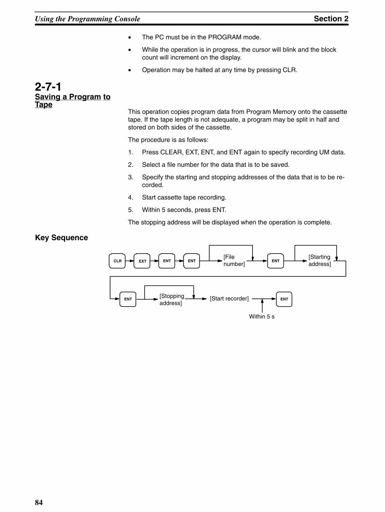
Using the Programming Console Section 2
84
• The PC must be in the PROGRAM mode.
• While the operation is in progress, the cursor will blink and the blockcount will increment on the display.
• Operation may be halted at any time by pressing CLR.
2-7-1Saving a Program toTape
This operation copies program data from Program Memory onto the cassettetape. If the tape length is not adequate, a program may be split in half andstored on both sides of the cassette.
The procedure is as follows:
1. Press CLEAR, EXT, ENT, and ENT again to specify recording UM data.
2. Select a file number for the data that is to be saved.
3. Specify the starting and stopping addresses of the data that is to be re-corded.
4. Start cassette tape recording.
5. Within 5 seconds, press ENT.
The stopping address will be displayed when the operation is complete.
Key Sequence
[Startingaddress]
CLR EXT ENT ENT[Filenumber]
ENT
ENT[Stoppingaddress]
[Start recorder] ENT
Within 5 s

Section 2Using the Programming Console
85
Example
Start recorder.Within 5 s
Flashing duringrecording
EXT
ENT
EB C D
A
41 2 3
0
ENT
ENT
ENT
E4
A
0A
0
ENT
2-7-2Restoring Program Data
This operation restores program data from a cassette tape and writes it toProgram Memory (UM).
The procedure is as follows:
1. Press CLEAR, EXT, and ENT to specify UM data.
2. Press the 1 key and ENT to specify restoring.
3. Enter the file number of the data that is to be restored and press ENT.
4. Specify the Program Memory starting address where the data is to berestored.
5. Start cassette tape playback.
6. Within 5 seconds, press ENT.
Data will be restored through the last address recorded on the tape, and thestopping address will be displayed.

Using the Programming Console Section 2
86
Key Sequence
CLR EXT ENTB
1 ENT[Filenumber]
ENT
[Startingaddress] [Start recorder] ENT
Within 5 s
Example
Start recorder.Within 5 s
Flashing duringrestoring
EXT
E4
C2
D3
B1
B1 ENT
ENT
ENT
ENT
2-7-3Verifying Program Data
This operation verifies that the contents of user Program Memory (UM) andthe cassette tape program data match.
The procedure is as follows:
1. Press CLEAR, EXT, and ENT to specify UM data.
2. Press the 2 key and ENT to specify verification.
3. Enter the file number of the data that is to be verified and press ENT.
4. Specify the Program Memory starting address of the data that is to beverified.
5. Start cassette tape playback.
6. Within 5 seconds, press ENT.
Data will be compared through the last address recorded on the tape, andeither OK or VER ERR will be displayed.

Section 2Using the Programming Console
87
Key Sequence
CLR EXT ENT ENT ENT
ENT
[Filenumber]
[Startingaddress] [Start recorder]
Within 5 s
C2
Example
Start recorder.Within 5 s
Flashing duringrecording
EXT
E4
C2
D3
B1
B1 ENT
ENT
ENT
ENT

Using the Programming Console Section 2
88
2-7-4DM<–> Cassette Tape:Save, Restore, and Verify
Procedures for Save/Restore/Verify operations for the DM area are identicalto those for the UM (Program Memory) except that the DM area is specifiedrather than Program Memory by inputting the 1 key before the first ENT input.It is also not necessary to input starting and stopping addresses when savingthe DM area; the entire area will be saved. Refer to the relevant operation inthe preceding sections 2-7-1 through 2-7-3. An example sequence for eachoperation is given below.
Key Sequence
CLRB
1
C2
[Saving]
[Restor-ing]
[Verify-ing]
ENT [File number]
[Start recorder] ENT
Within 5 s
EXT

Section 2Using the Programming Console
89
Example
EXT
ENT
E
B
C D4
1
2 3
ENT
B1
ENT
Saving
Start recorder.Within 5 s
Flashesduringsave
Restor-ing
Flashesduringrestore
ENT
E4
C2
D3
B1
ENT
Verifying
Start recorder.Within 5 s
Flashesduring verify
C2
ENT
E4
C2
D3
B1
ENT
Start recorder.Within 5 s
B1

90
SECTION 3Data and Memory Areas
3-1Overview
This section explains how I/O bits are used to identify individual I/O pointsand discusses the functions of the various types of data and memory areas inthe PC.
I/O ChannelsThe PC operates by monitoring input signals from such sources as pushbut-tons, sensors, and limit switches. Then, according to the program in its mem-ory, the PC reacts to the inputs by outputting signals to external loads suchas relays, motor controls, indicator lights, and alarms.
I/O channels are used to identify the bits that correspond to the external I/Opoints through which the PC interacts with physical devices.
Each channel consists of 16 I/O bits. The I/O bits are assigned addresses asdescribed below.
Addressing ConventionsI/O channel numbers are three-digit expressions and bit numbers are two-dig-it. Altogether, five digits are used to address a particular I/O bit. Examples ofI/O bit addresses are given below.
I/O Channel # + Bit # (0 - 15) ==> I/O address
Channel 63, bit 3 : 063 03 ==> 06303
Channel 3, bit 15 : 003 15 ==> 00315
Like I/O bit addresses, data and memory area locations are also referencedby specifying a channel number and a bit number.
When the data is read as a four-digit decimal or hexadecimal number, eachdigit represents a set of four bits in the channel (16 bits in all). The rightmostdigit of the decimal or hexadecimal number therefore represents the right-most four bits (3 to 0) of the channel.
One channel
15 14 13 12 11 10 9 8 7 6 5 4 3 2 1 0
3 2 1 0
If, for example, the ON/OFF status of the rightmost four bits is 0101 in binary,the corresponding digit would be 5 in decimal or hexadecimal. If the ON/OFFstatus is 1111 in binary, the hexadecimal number would be F (decimal 15).
Types of Data and Memory Areas
I/O bits are part of the I/O and Internal Relay (IR) Area. Bits that are not usedfor actual input or output operations constitute the remaining part of the IR
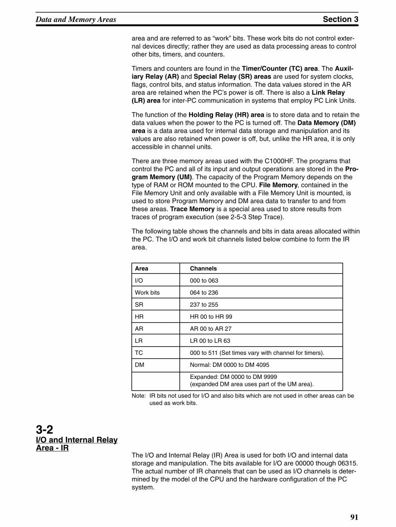
Section 3Data and Memory Areas
91
area and are referred to as “work” bits. These work bits do not control exter-nal devices directly; rather they are used as data processing areas to controlother bits, timers, and counters.
Timers and counters are found in the Timer/Counter (TC) area. The Auxil-iary Relay (AR) and Special Relay (SR) areas are used for system clocks,flags, control bits, and status information. The data values stored in the ARarea are retained when the PC’s power is off. There is also a Link Relay(LR) area for inter-PC communication in systems that employ PC Link Units.
The function of the Holding Relay (HR) area is to store data and to retain thedata values when the power to the PC is turned off. The Data Memory (DM)area is a data area used for internal data storage and manipulation and itsvalues are also retained when power is off, but, unlike the HR area, it is onlyaccessible in channel units.
There are three memory areas used with the C1000HF. The programs thatcontrol the PC and all of its input and output operations are stored in the Pro-gram Memory (UM). The capacity of the Program Memory depends on thetype of RAM or ROM mounted to the CPU. File Memory, contained in theFile Memory Unit and only available with a File Memory Unit is mounted, isused to store Program Memory and DM area data to transfer to and fromthese areas. Trace Memory is a special area used to store results fromtraces of program execution (see 2-5-3 Step Trace).
The following table shows the channels and bits in data areas allocated withinthe PC. The I/O and work bit channels listed below combine to form the IRarea.
Area Channels
I/O 000 to 063
Work bits 064 to 236
SR 237 to 255
HR HR 00 to HR 99
AR AR 00 to AR 27
LR LR 00 to LR 63
TC 000 to 511 (Set times vary with channel for timers).
DM Normal: DM 0000 to DM 4095
Expanded: DM 0000 to DM 9999 (expanded DM area uses part of the UM area).
Note: IR bits not used for I/O and also bits which are not used in other areas can beused as work bits.
3-2I/O and Internal RelayArea - IR
The I/O and Internal Relay (IR) Area is used for both I/O and internal datastorage and manipulation. The bits available for I/O are 00000 though 06315.The actual number of IR channels that can be used as I/O channels is deter-mined by the model of the CPU and the hardware configuration of the PCsystem.

Data and Memory Areas Section 3
92
I/O ChannelsThe channels shaded may not be used for I/O with the C1000HF. Thesechannels are used in Remote I/O Systems when the PC controls Remote I/OUnits.
Ch 066
00
01
02
03
04
05
06
07
08
09
10
11
12
13
14
15
Ch 000
00
01
02
03
04
05
06
07
08
09
10
11
12
13
14
15
Ch 001
00
01
02
03
04
05
06
07
08
09
10
11
12
13
14
15
Ch 061
00
01
02
03
04
05
06
07
08
09
10
11
12
13
14
15
Ch 062
00
01
02
03
04
05
06
07
08
09
10
11
12
13
14
15
Ch 063
00
01
02
03
04
05
06
07
08
09
10
11
12
13
14
15
Ch 064
00
01
02
03
04
05
06
07
08
09
10
11
12
13
14
15
Ch 065
00
01
02
03
04
05
06
07
08
09
10
11
12
13
14
15
Ch 125
00
01
02
03
04
05
06
07
08
09
10
11
12
13
14
15
Ch 126
00
01
02
03
04
05
06
07
08
09
10
11
12
13
14
15
Ch 127
00
01
02
03
04
05
06
07
08
09
10
11
12
13
14
15
Ch 002
00
01
02
03
04
05
06
07
08
09
10
11
12
13
14
15
Channel Number
Work Channels
Ch 130
00
01
02
03
04
05
06
07
08
09
10
11
12
13
14
15
Ch 064
00
01
02
03
04
05
06
07
08
09
10
11
12
13
14
15
Ch 065
00
01
02
03
04
05
06
07
08
09
10
11
12
13
14
15
Ch 125
00
01
02
03
04
05
06
07
08
09
10
11
12
13
14
15
Ch 126
00
01
02
03
04
05
06
07
08
09
10
11
12
13
14
15
Ch 127
00
01
02
03
04
05
06
07
08
09
10
11
12
13
14
15
Ch 128
00
01
02
03
04
05
06
07
08
09
10
11
12
13
14
15
Ch 129
00
01
02
03
04
05
06
07
08
09
10
11
12
13
14
15
Ch 234
00
01
02
03
04
05
06
07
08
09
10
11
12
13
14
15
Ch 235
00
01
02
03
04
05
06
07
08
09
10
11
12
13
14
15
Ch 236
00
01
02
03
04
05
06
07
08
09
10
11
12
13
14
15
Ch 066
00
01
02
03
04
05
06
07
08
09
10
11
12
13
14
15
Channel Number

Section 3Data and Memory Areas
93
Input Bit UsageInput bits can directly input external signals to the PC and can be used in anyorder in programming. They cannot be used for output instructions. As manyNO or NC inputs can be used as required as long as the I/O capacity of thePC is not exceeded. Any unused input bits can be used as work bits in pro-gramming. Input bits are used with LD, AND, OR, DIFU, DIFD, and other in-structions.
Output Bit UsageOutput bits are used to output program execution results and can be used inany order in programming. As many NO or NC outputs as required can beused as long as the I/O capacity of the PC is not exceeded. Any unused out-put bits can be used as work bits in programming. Output bits are used withOUT and OUT NOT.
I/O Unit Mounting Location
When mounting I/O Units to the PC Racks, any type of I/O Unit can bemounted in any order. I/O channel numbers will be assigned serially accord-ing to the mounting order of the I/O Units. The mounting order of the I/O Unitsmust then be registered using the I/O Table Register operation (see 2-2-4Registering the I/O Table). The registered I/O table can then be checked withthe I/O Table Read or I/O Table Verify operations. Note that vacant slots arenot registered. Space may be reserved using a Dummy I/O Unit. The I/O ta-ble can also be changed to allow for vacant slots or for other reasons (seeSlot Reservation, below).
The I/O channel numbers are automatically assigned in sequence to the I/OUnits mounted to the Racks. The top leftmost position is the starting point (i.e.00000; channel 000, bit 00) and bit numbers are assigned top to bottom, leftto right.
Starting position for I/O bit assignments CPU Rack
Expansion I/O Rack
Vacant slot to which no I/O Unit is mounted and which isnot reserved by either a Dummy I/O or the I/O TableChange operation.

Data and Memory Areas Section 3
94
Slot ReservationIf an I/O Unit is later mounted to an unreserved vacant slot, the I/O Unit loca-tions will disagree with the registered table and will cause an I/O verificationerror to occur. If an unplanned I/O Unit is required, change the programmedchannel numbers for the I/O Units to the right of the added I/O Unit and regis-ter the table again.
Likewise, if a mounted I/O Unit is replaced with an I/O Unit with a differentnumber of points, the channel numbers assigned to the I/O Units alreadymounted to the right of the new I/O Unit will need to be reassigned. The sameis also true when a mounted I/O Unit is removed from the Rack, resulting in avacancy.
The channel numbers will not be changed, however, if an I/O Unit is replacedwith another Unit having the same number of points.
Space can be reserved for future addition of an I/O Unit(s) with a Dummy I/OUnit or by changing the I/O table after it has been registered (see 2-2-6Changing the I/O Table).

Section 3Data and Memory Areas
95
3-3Special Relay Area SR
The SR area is used for monitoring system operation, generating clockpulses, and signalling errors. The SR area addresses range from 23700 to25515.
The following table lists the functions of SR area flags and control bits. Un-less otherwise stated, flags are OFF until the specified condition arises, thenthey are turned ON by the system. Restart bits are usually OFF, but when theuser turns one ON then OFF again, it will restart the specified link. Other con-trol bits are usually OFF until set by the user.
SR bits 25209 through 25215 can be turned ON and OFF from the program,i.e., they can be manipulated with output instructions. Other SR bits cannotbe changed from the program.
Ch Bit Function
237 00:07
Output area for end codes after execution ofSEND/RECV instructions when usingSYSMAC LINK
238:241
--- Output area for level 0 data link status whenusing SYSMAC LINK or SYSMAC NET
242:245
--- Output area for level 1 data link status whenusing SYSMAC LINK or SYSMAC NET
247 00:07
PC Link level 1, Units 24 to 31 Run flags(see Note)
08:15
PC Link level 1, Units 24 to 31 Error flags(see Note)
248 00:07
PC Link level 1, Units 16 to 23 Run flags(see Note)
08:15
PC Link level 1, Units 16 to 23 Error flags(see Note)
249 00:07
PC Link level 0, Units 8 to 15 Run flags(see Note)
08:15
PC Link level 0, Units 8 to 15 Error flags(see Note)
250 00:07
PC Link level 0, Units 0 to 7 Run flags(see Note)
08:15
PC Link level 0, Units 0 to 7 Error flags(see Note)
251 00:15
Remote I/O Error flags
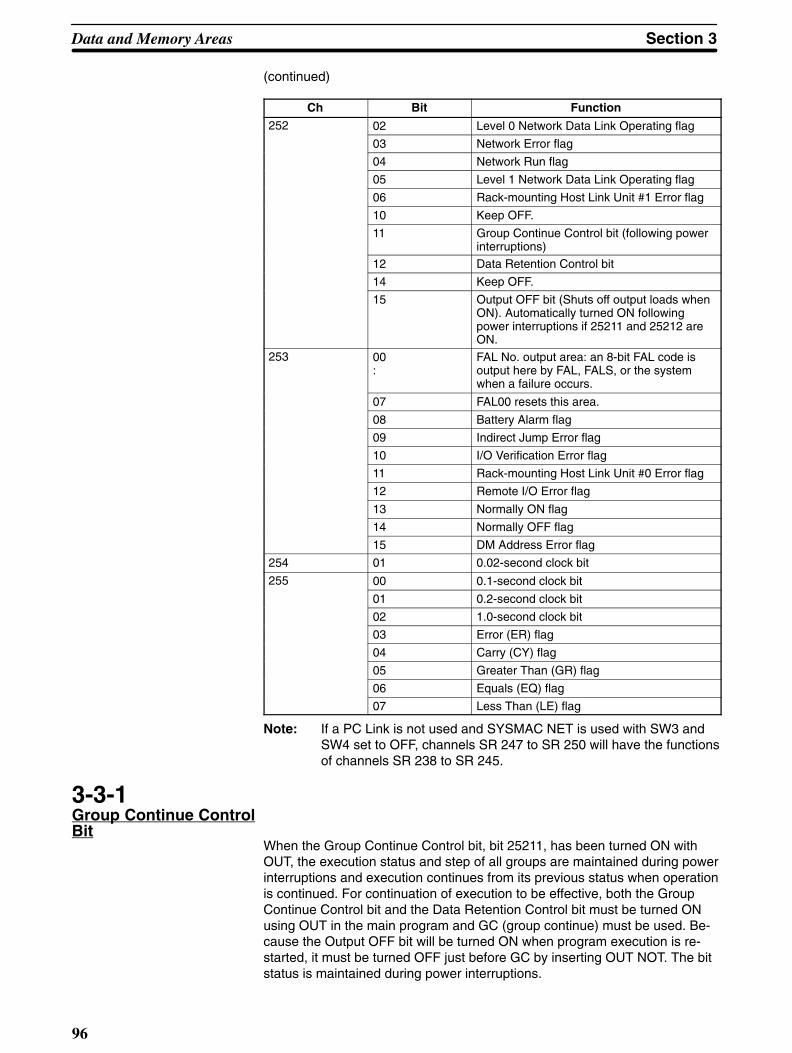
Data and Memory Areas Section 3
96
(continued)
Ch Bit Function
252 02 Level 0 Network Data Link Operating flag
03 Network Error flag
04 Network Run flag
05 Level 1 Network Data Link Operating flag
06 Rack-mounting Host Link Unit #1 Error flag
10 Keep OFF.
11 Group Continue Control bit (following powerinterruptions)
12 Data Retention Control bit
14 Keep OFF.
15 Output OFF bit (Shuts off output loads whenON). Automatically turned ON followingpower interruptions if 25211 and 25212 areON.
253 00:
FAL No. output area: an 8-bit FAL code isoutput here by FAL, FALS, or the systemwhen a failure occurs.
07 FAL00 resets this area.
08 Battery Alarm flag
09 Indirect Jump Error flag
10 I/O Verification Error flag
11 Rack-mounting Host Link Unit #0 Error flag
12 Remote I/O Error flag
13 Normally ON flag
14 Normally OFF flag
15 DM Address Error flag
254 01 0.02-second clock bit
255 00 0.1-second clock bit
01 0.2-second clock bit
02 1.0-second clock bit
03 Error (ER) flag
04 Carry (CY) flag
05 Greater Than (GR) flag
06 Equals (EQ) flag
07 Less Than (LE) flag
Note: If a PC Link is not used and SYSMAC NET is used with SW3 andSW4 set to OFF, channels SR 247 to SR 250 will have the functionsof channels SR 238 to SR 245.
3-3-1Group Continue ControlBit
When the Group Continue Control bit, bit 25211, has been turned ON withOUT, the execution status and step of all groups are maintained during powerinterruptions and execution continues from its previous status when operationis continued. For continuation of execution to be effective, both the GroupContinue Control bit and the Data Retention Control bit must be turned ONusing OUT in the main program and GC (group continue) must be used. Be-cause the Output OFF bit will be turned ON when program execution is re-started, it must be turned OFF just before GC by inserting OUT NOT. The bitstatus is maintained during power interruptions.

Section 3Data and Memory Areas
97
When the Group Continue Controlbit is OFF, all execution status for allgroups will be initialized when operation starts.
3-3-2Data Retention ControlBit
If the Data Retention Control bit, bit 25212, is ON, the current status of I/Obits, work bits, and LR bits are retained when changing from PROGRAMmode to MONITOR or RUN mode or vice versa. However, when power isturned on and off again, the status of all these data is cleared.
Turning OFF the Data Retention Control bit clears this data when PC opera-tion starts or stops. This bit is normally OFF. Bit status is maintained forpower failures.
3-3-3Output OFF Bit
When the Output OFF bit, bit 25215, is ON, all outputs to the Output Units areinhibited and the OUT INHB. indicator on the front panel of the CPU is lit.
When the Output OFF bit is OFF, Output Units are refreshed normally. TheOutput OFF bit is normally OFF, and bit status is maintained for power fail-ures.
3-3-4FAL Error Code OutputArea
The FAL error code is output to bits 25300 to 25307.
FAL(35) or FALS(36) execution outputs a 2-digit BCD FAL code (for error di-agnosis) to these 8 bits. The system also outputs a FAL code here when analarm output occurs, such as one caused by battery failure.
This area can be reset by executing FAL(35) 00 or through a Failure ReadProgramming Console operation. (See 4-14-2)
3-3-5Battery Alarm Flag
When the Battery Alarm flag, bit 25308, is ON, it indicates that the supplyvoltage of the CPU or File Memory Unit backup battery has dropped. Thewarning indicator lamp on the front panel of the CPU will also be lit.
3-3-6Indirect Jump Error Flag
The Indirect Jump Error flag, bit 25309, turns ON when an undefined label fora jump destination is used for an indirect jump or when a label number is notBCD. If the label number is not BCD, the Instruction Execution Error flag, ER,will also be ON.
3-3-7I/O Verification Error Flag
The I/O Verification Error flag, bit 25310, turns ON when the number of I/OUnits mounted on the CPU Rack and Expansion I/O Racks disagrees with theI/O table registered.
3-3-8DM Address Error Flag
The DM Address Error flag, bit 25315, turns ON if an expanded DM area isdesignated when an expanded DM area is not being used or if the contents of

Data and Memory Areas Section 3
98
an indirectly addressed DM area are not BCD. The Instruction Execution Er-ror flag, ER, will also be ON in either case.
3-3-9Instruction ExecutionError Flag, ER
Attempting to execute an instruction with incorrect data turns the ER flag, bit25503, ON. Common causes of an instruction error are non-BCD operanddata when BCD data is required, or an indirectly addressed DM channel thatis non-existent. When the ER flag is ON, the current instruction will not beexecuted.
3-3-10Arithmetic OperationFlagsCarry Flag, CY
The CY flag, bit 25504, turns ON when there is a carry in the result of anarithmetic operation, or when a rotate or shift instruction moves a “1” into CY.This flag is set and cleared by STC and CLC, respectively. Be sure to useCLC before any instruction using CY. (See 4-9-3)
Greater Than Flag, GRThe GR flag, bit 25505, turns ON when the result of CMP (compare) showsthe second of two operands to be greater than the first.
Equal Flag, EQThe EQ flag, bit 25506, turns ON when the result of CMP (compare) showstwo operands to be equal, or when the result of an arithmetic operation iszero.
Less Than Flag, LEThe LE flag, bit 25507, turns ON when the result of CMP (compare) showsthe second of two operands to be less than the first.
3-3-11Clock Bits
Four clock bits are available to control program timing. Each clock bit is ONfor the first half of the rated pulse time, then OFF for the second half. In otherwords, each clock pulse has a duty factor of 1 to 1.

!
Section 3Data and Memory Areas
99
0.5s0.5s
0.05 s
Pulse width 1 min 0.02 s 0.1 s 1.0 s
Bit 25400 25401 25500 25502
Generates 1-min clock pulse
30s 30s
1 minBit 25400
Generates 0.1-s clock pulse
0.1 sBit 25500
Generates 0.2-s clock pulse
0.1s 0.1s
0.2 sBit 25501
Generates 0.02-s clock pulse
0.01s 0.01s 0.02 sBit 25401
Generates 1-s clock pulse
1 sBit 25502
0.05 s
Caution Because the 0.1-second and 0.02-second clock pulses have ON times of 50 and10 ms, respectively, the CPU may not be able to accurately read the pulse if pro-gram execution time is too long.
3-3-12Special I/O Flags andControl Bits
Use of the following SR flags and control bits depends on the particular con-figuration of your PC system. These flags and control bits are used whencomponents such as PC Link Units, Remote I/O Units, Network Link Units, orHost Link Units are contained within the PC system. For additional informa-tion, consult the System Manual for the particular Units involved.
The following bits can be employed as work bits when the special type of Unitassociated with them is not connected to the system.
• PC Link Error and RUN FlagsWhen PC Link Units are used in the system, channels 247 to 250 are used tomonitor the operating status of up to 32 PC Link Units.

Data and Memory Areas Section 3
100
Channel PC Link Units
247 Nos 24 to 31
248 Nos 16 to 23
249 Nos 8 to 15
250 Nos 0 to 7
For each channel, bits 00 to 07 are ON when the Unit is in RUN mode andbits 08 to 15 are ON when an error occurs in the corresponding PC Link Unit.
Bit no.
00
01
02
03
04
05
06
07
08
09
10
11
12
13
14
15
Ch 247
24(#1-8)
25(#1-9)
26(#1-10)
27(#1-11)
28(#1-12)
29(#1-13)
30(#1-14)
31(#1-15)
24(#1-8)
25(#1-9)
26(#1-10)
27(#1-11)
28(#1-12)
29(#1-13)
30(#1-14)
31(#1-15)
Ch 248
16(#1-0)
17(#1-1)
18(#1-2)
19(#1-3)
20(#1-4)
21(#1-5)
22(#1-6)
23(#1-7)
16(#1-0)
17(#1-1)
18(#1-2)
19(#1-3)
20(#1-4)
21(#1-5)
22(#1-6)
23(#1-7)
Ch 249
8(#0-8)
9(#0-9)
10(#0-10)
11(#0-11)
12(#0-12)
13(#0-13)
14(#0-14)
15(#0-15)
8(#0-8)
9(#0-9)
10(#0-10)
11(#0-11)
12(#0-12)
13(#0-13)
14(#0-14)
15(#0-15)
Ch 250
0(#0-0)
1(#0-1)
2(#0-2)
3(#0-3)
4(#0-4)
5(#0-5)
6(#0-6)
7(#0-7)
0(#0-0)
1(#0-1)
2(#0-2)
3(#0-3)
4(#0-4)
5(#0-5)
6(#0-6)
7(#0-7)
The numbers in parentheses indicate the Unit number and the link level. Forexample, if, as shown below, the contents of channel 248 are 02FF, then itmeans that Units 0 to 7 of link level 1 are in RUN mode, and Unit 1 of linklevel 1 has an error.
0000 0010 1111 1111
0 2 F F

Section 3Data and Memory Areas
101
• PC Link Restart BitThe PC Link Restart bits are turned ON then OFF to restart the PC Link Sys-tem.
Link level
# 0
# 1
Bit
25214
25210
• Remote I/O Error FlagsChannel 251 is used for Remote I/O Unit Error flags. The functions of each bitare described below. Refer to the appropriate Remote I/O System Manual forfurther details.
Bit 00
If there are errors in more than one Remote I/O Unit, they can be read byturning this bit ON and OFF.
Bits 01 and 02
Not used (not accessible).
Bit 03
Indicates that an error has occurred in a Remote I/O Unit or an Optical Trans-mitting I/O Unit.
Bit 04
Indicates which Optical Transmitting I/O Unit has failed. This bit is ON if theUnit assigned to the “H” (high) channel bits fails and OFF if the “L” channel-bits Unit fails.
Bits 05 and 06
Indicate the number of the rack (0 to 3) to which the error-generating OpticalTransmitting I/O Unit is mounted.
Bit 07
Indicates an error in a Remote I/O Master Unit.
Bits 08 to 15
Depending on which kind of Unit is in error, bits 08 to 15 will indicate one ofthe following:
•The Remote I/O Master Unit number (B0 to B7) in which the error occurred.
•The Optical Transmitting I/O Unit channel number (00 to 31) in which the I/Oerror occurred.
•The I/O Link Unit channel number (00 to 31) in which the I/O error occurred.
• I/O Bus Error and Run FlagsThese flags indicate the state of the I/O Bus system.
Flag Bit
Error Flag 25203
Run Flag 25204
Link Operating flag 25205

Data and Memory Areas Section 3
102
• Host Link Error FlagsA Host Link Error flag turns ON if an error occurs in a Host Link Unit on thePC. The PC has two Host Link Error flags, one to indicate an error in HostLink Unit #0 (bit 25311), and the other to indicate an error in Host Link Unit #1(bit 25206).
3-4Holding Relay Area - HR
The HR area is used to store and manipulate various kinds of data. Its ad-dresses range from HR 0000 through HR 9915.
HR bits retain status when the system operating mode changes and also dur-ing power failure. HR bits used between IL and ILC also retain status duringinterlocks (see 4-2-3) and HR bits in group programs retain status when GEand GOFF are executed.
To access HR bits, prefix the address number with “HR” (e.g., HR 0101 for bit01 in HR channel 01) by pressing SHIFT and then HR/NOT on the Program-ming Console. HR bits can be used in any order and as often as required in aprogram.
HR97
00
01
02
03
04
05
06
07
08
09
10
11
12
13
14
15
HR02
00
01
02
03
04
05
06
07
08
09
10
11
12
13
14
15
HR06
00
01
02
03
04
05
06
07
08
09
10
11
12
13
14
15
HR05
00
01
02
03
04
05
06
07
08
09
10
11
12
13
14
15
HR03
00
01
02
03
04
05
06
07
08
09
10
11
12
13
14
15
HR00
00
01
02
03
04
05
06
07
08
09
10
11
12
13
14
15
HR01
00
01
02
03
04
05
06
07
08
09
10
11
12
13
14
15
HR04
00
01
02
03
04
05
06
07
08
09
10
11
12
13
14
15
HR07
00
01
02
03
04
05
06
07
08
09
10
11
12
13
14
15
HR98
00
01
02
03
04
05
06
07
08
09
10
11
12
13
14
15
HR99
00
01
02
03
04
05
06
07
08
09
10
11
12
13
14
15
Channel No./ Bit No.
3-5Auxiliary Relay Area - AR
Part of the AR area is available for internal data storage and manipulation,i.e., AR 0800 through AR 1715, AR 2200 through AR 2215, and AR 2500through AR 2715, and may be accessed by the user and used in the sameway as HR bits. The rest of the AR area is reserved for various system func-tions, as described in the tables on the following pages. These bits are onlyoperative in MONITOR or RUN mode. Except where otherwise indicated, theAR bits dedicated for system use are updated periodically by the system.
The AR area also retains data status during a power failure except for AR2400 through AR 2405, which are reset to 0 whenever PC power is turned

Section 3Data and Memory Areas
103
on, or when switching from MONITOR or RUN mode to PROGRAM mode orfrom PROGRAM mode to MONITOR or RUN mode.
To access bits in this area from the Programming Console, prefix the addressnumber with “AR” (e.g., AR 0700) by pressing SHIFT and then CNR.
AR Channels
AR16
00
01
02
03
04
05
06
07
08
09
10
11
12
13
14
15
AR15
00
01
02
03
04
05
06
07
08
09
10
11
12
13
14
15
AR00
00
01
02
03
04
05
06
07
08
09
10
11
12
13
14
15
AR25
00
01
02
03
04
05
06
07
08
09
10
11
12
13
14
15
AR01
00
01
02
03
04
05
06
07
08
09
10
11
12
13
14
15
AR17
00
01
02
03
04
05
06
07
08
09
10
11
12
13
14
15
AR14
00
01
02
03
04
05
06
07
08
09
10
11
12
13
14
15
AR18
00
01
02
03
04
05
06
07
08
09
10
11
12
13
14
15
AR26
00
01
02
03
04
05
06
07
08
09
10
11
12
13
14
15
AR27
00
01
02
03
04
05
06
07
08
09
10
11
12
13
14
15
Channel No./ Bit No.

Data and Memory Areas Section 3
104
AR Area Flags andControl Bits
Ch Bit Function
00 00: 15
Group Execution flags for group programs 0 through 15. If the flag is ON, a specific groupprogram is awaiting execution, is actually being executed, or is being temporarily held.The flag turns ON for a specific group program when GS is executed for it and turns OFFwhen GOFF or GEND is executed for it.
01 00: 15
Group Execution flags for group programs 16 through 31 (0100: 16, 0101: 17, etc.)
02 00: 15
Group Execution flags for group programs 32 through 47 (0200: 32, 0201: 33, etc.)
03 00: 15
Group Execution flags for group programs 48 through 63 (0300: 48, 0301: 49, etc.)
04 00: 15
Group Execution flags for group programs 64 through 79 (0400: 64, 0401: 65, etc.)
05 00: 15
Group Execution flags for group programs 80 through 95 (0500: 80, 0501: 81, etc.)
06 00: 15
Group Execution flags for group programs 96 through 111 (0600: 96, 0601: 97, etc.)
07 00: 15
Group Execution flags for group programs 112 through 127 (0700: 112, 0701: 113, etc.)
08 00: 15
SYSMAC LINK Network Status flags for level 0 nodes 1 through 16 (0800: node 1, 0801:node 2, etc.) Turn ON if the corresponding node is part of a SYSMAC LINK Network.Refreshed at each cycle when operating in SYSMAC LINK.
09 00: 15
SYSMAC LINK Network Status flags for level 0 nodes 17 through 32 (0900: node 17,0901: node 18, etc.)
10 00: 15
SYSMAC LINK Network Status flags for level 0 nodes 33 through 48 (1000: node 33,1001: node 34, etc.)
11 00: 13
SYSMAC LINK Network Status flags for level 0 nodes 49 through 62 (1100: node 49,1101: node 50, etc.)
14 Communications Controller Error flag
15 EEPROM Error flag
12 00: 15
SYSMAC LINK Network Status flags for level 1 nodes 1 through 16 (1200: node 1, 1201:node 2, etc.) Turn ON if the corresponding node is part of a SYSMAC LINK Network.Refreshed at each cycle when operating in SYSMAC LINK.
13 00: 15
SYSMAC LINK Network Status flags for level 1 nodes 17 through 32 (1300: node 17,1301: node 18, etc.)
14 00: 15
SYSMAC LINK Network Status flags for level 1 nodes 33 through 48 (1400: node 33,1401: node 34, etc.)
15 00: 13
SYSMAC LINK Network Status flags for level 1 nodes 49 through 62 (1500: node 49,1501: node 50, etc.)
14 Communications Controller Error flag
15 EEPROM Error flag
16 00: 15
Level 0 network link servicing time. Calculates the servicing time for each CPU Unit cyclein the network and outputs it in BCD (000.0 ms to 999.9 ms).

Section 3Data and Memory Areas
105
Ch FunctionBit
17 00: 15
Level 1 network link servicing time.
18 12 Trace Complete flag
13 Tracing flag
14 Trace Start bit (Written to by the user program)
15 Sampling Start bit
19 00 File Memory Unit Error Reset bit. At the leading edge of the ON pulse, bits AR 1903through AR 1906 are reset.
01 FM Data Transfer flag (For program-initiated transfer)
02 Transfer Direction flag (ON for user program write to FM; OFF for read from FM)
03 Attempt made to write different type of FM block to the CPU memory
04 FM write to a write-protected FM block was attempted
05 Unsuccessful FM write attempt to EEP-ROM FM
06 Checksum error during FM read
07 File Memory Unit Battery Alarm flag
08 Blocks 0 to 249 FM Write-Protect bit (see Note)
09 Blocks 250 to 499 FM Write-Protect bit (see Note)
10 Blocks 500 to 749 FM Write-Protect bit (see Note)
11 Blocks 750 to 999 FM Write-Protect bit (see Note)
12 Blocks 1,000 to 1,249 FM Write-Protect bit (see Note)
13 Blocks 1,250 to 1,499 FM Write-Protect bit (see Note)
14 Blocks 1,500 to 1,749 FM Write-Protect bit (see Note)
15 Blocks 1,750 to 1,999 FM Write-Protect bit (see Note)
20 00 A 4-digit BCD number that indicates the number of the FM block currently beingtransferred by the program. Updated every time a block is transferred.
21 00 A 4-digit BCD number that indicates the remaining number of blocks to be transferredto/from FM. This number is decremented every time a block is transferred.
22 00: 07
SYSMAC LINK Data Link Setting bits (See the tables on the following page.)
23 00 Power-on counter: a 4-digit BCD number showing how many times the power has beenturned on. Be sure to reset this bit as necessary.
24 00 ON when servicing of PC Link Subsystem assigned level 1 is stopped.
01 ON when servicing of PC Link Subsystem assigned level 0 or a single-level PC LinkSystem is stopped.
02 ON when servicing of Network Link or Host Link Unit #1 is stopped.
03 ON when servicing of Network Link or Host Link Unit #0 is stopped.
04 ON when servicing of peripheral tools is stopped.
05 ON when servicing of periodic I/O updating or a Remote I/O System is stopped.
06 ON when the actual value for the network parameter (greatest node address) of level 1SYSMAC LINK differs from the value set with FIT.
07 ON when the actual value for the network parameter (greatest node address) of level 0SYSMAC LINK differs from the value set with FIT.
10 Used in combination with FUN(49). When this bit is turned ON by the user, servicingsystem Units will take priority over executing instructions. Reset to 0 when PC power isturned on.
11 PC Link Level 1 Connected flag
12 PC Link Level 0 (or single-level system) Connected flag
13 Network Link or Host Link Unit #1 Connected flag
14 Host Link Unit #0 Connected flag
15 CPU-mounted device Connected flag
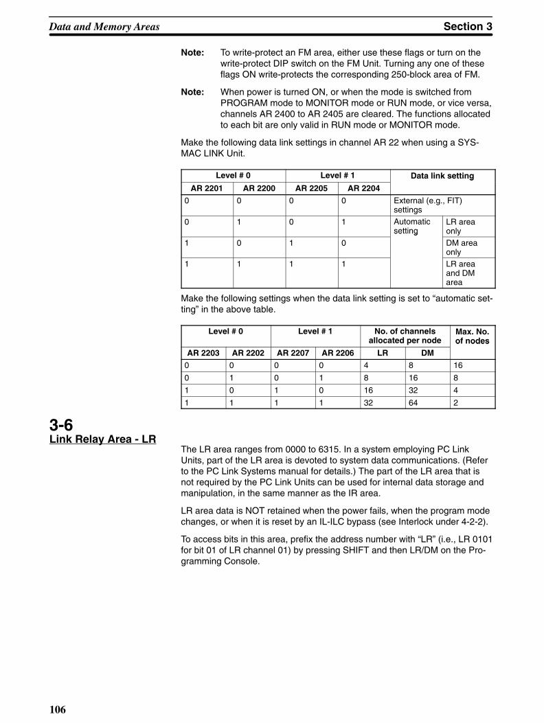
Data and Memory Areas Section 3
106
Note: To write-protect an FM area, either use these flags or turn on thewrite-protect DIP switch on the FM Unit. Turning any one of theseflags ON write-protects the corresponding 250-block area of FM.
Note: When power is turned ON, or when the mode is switched fromPROGRAM mode to MONITOR mode or RUN mode, or vice versa,channels AR 2400 to AR 2405 are cleared. The functions allocatedto each bit are only valid in RUN mode or MONITOR mode.
Make the following data link settings in channel AR 22 when using a SYS-MAC LINK Unit.
Level # 0 Level # 1 Data link setting
AR 2201 AR 2200 AR 2205 AR 2204
g
0 0 0 0 External (e.g., FIT)settings
0 1 0 1 Automaticsetting
LR areaonly
1 0 1 0
se g
DM areaonly
1 1 1 1 LR areaand DMarea
Make the following settings when the data link setting is set to “automatic set-ting” in the above table.
Level # 0 Level # 1 No. of channelsallocated per node
Max. No.of nodes
AR 2203 AR 2202 AR 2207 AR 2206 LR DMo odes
0 0 0 0 4 8 16
0 1 0 1 8 16 8
1 0 1 0 16 32 4
1 1 1 1 32 64 2
3-6Link Relay Area - LR
The LR area ranges from 0000 to 6315. In a system employing PC LinkUnits, part of the LR area is devoted to system data communications. (Referto the PC Link Systems manual for details.) The part of the LR area that isnot required by the PC Link Units can be used for internal data storage andmanipulation, in the same manner as the IR area.
LR area data is NOT retained when the power fails, when the program modechanges, or when it is reset by an IL-ILC bypass (see Interlock under 4-2-2).
To access bits in this area, prefix the address number with “LR” (i.e., LR 0101for bit 01 of LR channel 01) by pressing SHIFT and then LR/DM on the Pro-gramming Console.

Section 3Data and Memory Areas
107
LR05
00
01
02
03
04
05
06
07
08
09
10
11
12
13
14
15
LR04
00
01
02
03
04
05
06
07
08
09
10
11
12
13
14
15
LR00
00
01
02
03
04
05
06
07
08
09
10
11
12
13
14
15
LR61
00
01
02
03
04
05
06
07
08
09
10
11
12
13
14
15
LR01
00
01
02
03
04
05
06
07
08
09
10
11
12
13
14
15
LR06
00
01
02
03
04
05
06
07
08
09
10
11
12
13
14
15
LR03
00
01
02
03
04
05
06
07
08
09
10
11
12
13
14
15
LR07
00
01
02
03
04
05
06
07
08
09
10
11
12
13
14
15
LR62
00
01
02
03
04
05
06
07
08
09
10
11
12
13
14
15
LR63
00
01
02
03
04
05
06
07
08
09
10
11
12
13
14
15
Channel No./ Bit No.
LR02
00
01
02
03
04
05
06
07
08
09
10
11
12
13
14
15
3-7Timer/Counter Area - TC
The TC area, addresses for which range from 000 to 511, is a single dataarea in which timer and counter data is stored for use by TIM, TIMS, CNT,and CNTR. This area is accessible in channel units only, which serve as thestorage area for the set value (SV) and the present value (PV) of the timer/counter. Timer/counter numbers are three digits. To specify a timer or acounter, prefix the three-digit TC number with “TIM” or CNT” (e.g., TIM 001 orCNT 126) or, for TIMS and CNTR, prefix the number with the appropriateFUN code (see Section 4 Programming Instructions).
Once a given TC address has been specified as the number for TIM, TIMS,CNT, or CNTR, that same address cannot be specified again for any othertimer or counter. For example, if TIM 010 has been specified in a program, asubsequent attempt to specify CNT 010 will generate an error.
Specifying the SV for TIM and TIMS varies with the timer number used (see4-4-1 and 4-4-2 for details).
The TC area retains the SV of both timers and counters during power failure.The PV of timers is reset when operations are initialized, when CNR is exe-cuted, when the IL condition is OFF (i.e., during interlocks), and when GOFFis executed. The PV of counters is reset when operations are initialized andwhen CNR is executed, but not during interlocks nor when GOFF is exe-cuted.
3-8Data Memory Area - DM
The DM area is used for internal data storage and manipulation and is acces-sible only in 16-bit channel units. The DM area retains data during power fail-ure. If a RAM Unit is used in the CPU, 5,964 words of the Program Memory

Data and Memory Areas Section 3
108
area can be converted for usage as Expanded DM area (see 2-2-3 Settingand Cancelling Expanded DM Area).
Converting Program Memory for use as expanded DM area naturally reducesthe amount of Program Memory available for user programs. Also, if the userprogram is converted to ROM, the expanded DM area will also be convertedto ROM. DM area ranges are as follows:
Normal DM 0000 to DM 4095
Expanded DM 0000 to DM 9999
DM or expanded DM area cannot be used by instructions with bit-size oper-ands, such as LD, OUT, AND, and OR.
Indirect AddressingNormally, when data is specified for an instruction, the instruction operation isperformed directly on that data. For example, suppose CMP (compare) withIR 005 as the first operand and DM 0010 as the second operand is used inthe program. When this instruction is executed, the data in IR 005 is com-pared with that in DM 0010.
It is possible, however to use indirect DM addresses as operands for instruc-tions. If *DM 0100 is specified as the data for a programming instruction, thecontent of DM 0100 specifies another DM channel at which the actual oper-and data is to be found. If, in this case, the content of DM 0100 is 0324, then*DM 0100 is the same as DM 0324 and the data that the program instructionactually uses is the content of DM 0324.
To access bits in the DM area, prefix the address number with “DM” (i.e., DM01 for DM channel 01) by pressing LR/DM on the Programming Console. Toindirectly address a DM channel, prefix the channel that contains the addressof the channel whose contents is to be used, with “*DM” by by pressingSHIFT and then */CH on the Programming Console.
3-9Program Memory
Program Memory is where the user program is stored. The amount of Pro-gram Memory available depends on the type of Memory Unit attached to thePC. Memory Units come in different types, such as RAM and ROM Units, andfor each type there are different sizes. (Refer to the Installation Guide for de-tails.)
To store instructions in Program Memory, input the instructions through theProgramming Console, or download programming data from an FIT, floppydisk, cassette tape, or host computer, or from a File Memory Unit if one ismounted to the CPU Rack (see end of Appendix A Standard Products for in-formation on FIT and other special products).
3-10File Memory Area - FM
The File Memory area is available only when a File Memory Unit is mountedto the PC. This area can be used for internal data storage and manipulation,and for storing additional PC programs for system flexibility. The area is ac-cessible in block units only. The block numbers are four digits, and eachblock consists of 128 channels.

Section 3Data and Memory Areas
109
File Memory addresses range from 0000 through 999 or from 0000 through1999, depending on the model of File Memory Unit that is used (see Appen-dix A Standard Models and 4-16 File Memory instructions).
The FM area retains data during power failure.

110
Section 4Programming Instructions
4-1Introduction
The C1000HF PC has a large programming instruction set that allows foreasy programming of complicated control processes. Each instruction’s ex-planation includes the flowchart symbol, data areas, and flags used with theinstruction. Examples of how to use some of the more complicated instruc-tions are also provided.
The many instructions provided by the C1000HF are described in followingsubsections by instruction group. These groups include Basic, Flow Control,Timer and Counter, Group Program, Subroutine and Interrupt Control, DataShift, Data Movement, Data Comparison, Data Conversion, Binary Calcula-tion, BCD Calculation, Logic, Special, Intelligent I/O Unit, and Network In-structions.
4-1-1Inputting Instructions
Basic instructions are input using the Programming Console keys providedfor them (see Section 2 Using the Programming Console). All other instruc-tions are input using function codes, of which there are two types: flowchartfunction codes and ladder diagram function codes.
To input a flowchart function code, which will be indicated after the instructionacronym between normal parentheses, press FUN, the function code, andENT on the Programming Console. Ladder diagram function codes are usedfor some instructions. To input a ladder diagram function code, which will beindicated after the instruction acronym between pointed parentheses (like this<00>), press SHIFT first, and then press FUN, the function code, and ENT.
If both a ladder and a flowchart function code are provided for an instruction,either may be used to input the instruction. In explanations, only one functioncode will be provided for each instruction, the flowchart function code, if thereis one, and if not, the ladder diagram function code. If no function code is giv-en, then there should be a Programming Console key for that instruction.
After inputting the instruction itself, each operand required for the instructionmust be input. After inputting each operand, you must press ENT before en-tering the next operand or the next instruction. In the flowchart symbols givenin following subsections for any instructions, operands are listed on lines un-der the instruction line; ENT must be pressed at the end of each of theselines, i.e., once for the instruction (unless a Programming Console key isavailable) and once after each operand line.
Note: Input function codes with care and be sure to press SHIFT whenrequired. If the wrong number is input or if SHIFT is not input whenrequired, an incorrect instruction will result.

Section 4Programming Instructions
111
ExampleThe BCD Add instruction, ADD(53), may be input using either of the followingkey sequences:
Using Flowchart Function code
Using Ladder Diagram Function code
FUNF
5D
3 ENT
SHIFT FUND
3A
0 ENT
After completing either of the above key sequences, the augend, the addend,and the channel where the result is to be placed would need to be desig-nated, pressing ENT after each of these three operands (see 4-8-4 BCD Add- ADD(53)<30>).
Some instructions require numbers that are integral parts of the instruction.These numbers are not considered as operands because they serve more toidentify the instruction. For example, SBN(31), which defines the beginning ofa subroutine, requires a number that identifies the subroutine so that it can beaccessed by other instructions. This number, identified as N, is input as partof the instruction line, i.e. it is input between the function code and ENT. ForSBN(31) 006 (i.e., the first instruction in subroutine 6), either of the followingkey sequences may be used.
FUN
Using Flowchart Function code
Using Ladder Diagram Function code
D3
B1
A
0A
0 6 ENT
SHIFT FUN 9C
2A
0A
0 6 ENT
Refer to 4-12-2 Subroutine Definition - SBN(31)<92> and RET(33)<93> fordetails on subroutines.
4-1-2Instruction Operand DataAreas and Flags
For each instruction, the Data Areas and Flags subsections list the dataareas that can be specified for each operand required for the instruction andthe flags that are applicable to it.
All consecutive channels required for any single operand must be in the samedata area. When only the first of these channels is input, be careful not to ex-ceed the last channel in the area you have selected. For example, if twochannels are required, you may not input SR channel 255 or AR 27. If boththe IR and SR areas are available for an operand, however, channels desig-

Programming Instructions Section 4
112
nated for operands may cross over from channel 246 to channel 247. Basi-cally, all the channel numbers for a single operand must have the same prefix(or, as in the case of IR and SR, no prefix).
Unless a limit is specified, any bit/channel in the area can be used. Refer toSection 2 I/O Assignments and Data Areas for the address of each flag andcontrol bit. The following abbreviations are used.
Data AreasIR: I/O and Internal Relay Area (bits 00000 through 24615, channels 000
through 246)
SR: Special Relay Area (bits 24700 through 25515, channels 247 through255; see note below)
HR: Holding Relay Area (bits HR 0000 through HR 9915, channels HR 00through HR 99)
AR: Auxiliary Relay Area (bits AR 0000 through AR 2715, channels AR 00through AR 27)
LR: Link Relay Area (bits LR 0000 through LR 6315, channels LR 00 throughLR 63)
TC: Timer/Counter Area (numbers TC 000 through TC 511)
DM: Data Memory Area (see note below)
#: Constants (see note below)
Note: In the SR area, only bits 25209 through 25215 can be manipulatedby the program.
When the DM area is specified for an operand, an indirect addresscan be used unless otherwise specified (*DM indicates an indirectData Memory address). If expanded DM area has been specified,DM 0000 through DM 9999 can be addressed; if expanded DMarea has not been specified, the normal upper limit of the area (DM4095) must not be exceeded.
The range in which a number can be specified for a given constantdepends on the particular instruction that uses it. If the constant isto specify a data area channel, it must correspond to an allowablechannel address within the data area. If the constant is a value tobe contained within a channel, it may be hexadecimal or decimal,as required by the instruction.
FlagsER: Error flagCY: Carry flagEQ: Equals flagGR: Greater Than flagLE: Less Than flagER is the flag most often used for monitoring an instruction’s execution.When ER goes ON, it indicates that an error has occurred in attempting toexecute the current instruction. The Flags subsection of each instruction listspossible reasons for ER being ON. ER will turn ON for any instruction if oper-ands are not input within established parameters.
TIM, TMS, CNT, and CNTR<12> (timer and counter instructions) are ex-ecuted when ER is ON. All other instructions, unless specifically specified,are not executed when ER is ON.
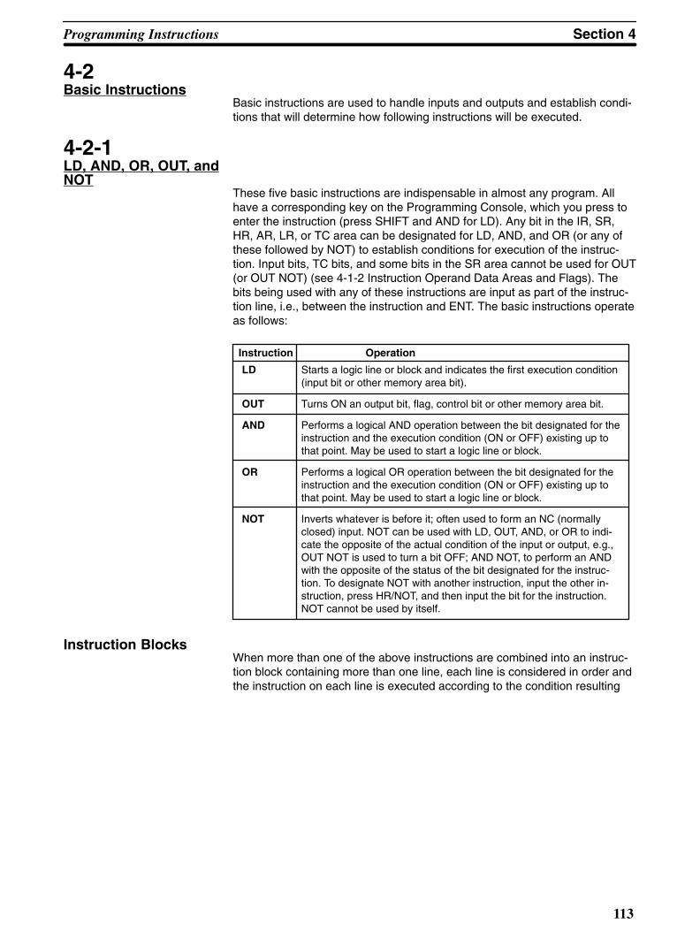
Section 4Programming Instructions
113
4-2Basic Instructions
Basic instructions are used to handle inputs and outputs and establish condi-tions that will determine how following instructions will be executed.
4-2-1LD, AND, OR, OUT, andNOT
These five basic instructions are indispensable in almost any program. Allhave a corresponding key on the Programming Console, which you press toenter the instruction (press SHIFT and AND for LD). Any bit in the IR, SR,HR, AR, LR, or TC area can be designated for LD, AND, and OR (or any ofthese followed by NOT) to establish conditions for execution of the instruc-tion. Input bits, TC bits, and some bits in the SR area cannot be used for OUT(or OUT NOT) (see 4-1-2 Instruction Operand Data Areas and Flags). Thebits being used with any of these instructions are input as part of the instruc-tion line, i.e., between the instruction and ENT. The basic instructions operateas follows:
Instruction Operation
LD Starts a logic line or block and indicates the first execution condition(input bit or other memory area bit).
OUT Turns ON an output bit, flag, control bit or other memory area bit.
AND Performs a logical AND operation between the bit designated for theinstruction and the execution condition (ON or OFF) existing up tothat point. May be used to start a logic line or block.
OR Performs a logical OR operation between the bit designated for theinstruction and the execution condition (ON or OFF) existing up tothat point. May be used to start a logic line or block.
NOT Inverts whatever is before it; often used to form an NC (normallyclosed) input. NOT can be used with LD, OUT, AND, or OR to indi-cate the opposite of the actual condition of the input or output, e.g.,OUT NOT is used to turn a bit OFF; AND NOT, to perform an ANDwith the opposite of the status of the bit designated for the instruc-tion. To designate NOT with another instruction, input the other in-struction, press HR/NOT, and then input the bit for the instruction.NOT cannot be used by itself.
Instruction BlocksWhen more than one of the above instructions are combined into an instruc-tion block containing more than one line, each line is considered in order andthe instruction on each line is executed according to the condition resulting

Programming Instructions Section 4
114
from all lines up to that point. Consider the following flowchart block.
LD 00000
AND 00001
OR 00002
OR NOT 00003
AND NOT TIM 000
OR HR 0000
AND NOT 0004
Here, the result of ANDing 00001 with 00000 (indicated with LD) is ORed with00002 and then the result is OR NOTed with 00003, i.e., the result up to ORNOT 00003 in this block will be ON if 00002 is ON, if 00003 is OFF, or if both00000 and 00001 are ON. The result up to this point will be OFF if none ofthese conditions are met. For convenience we’ll call the status at this pointCondition 1.
An AND NOT is then executed between Condition 1 and TIM 000, the resultis ORed with HR 0000, and the result of this is AND NOTed with 00004, i.e.,the final condition of this block is ON only if 00004 is OFF and either HR 0000is ON, or Condition 1 is ON and TIM 000 is OFF.
As described above, an “execution condition” is created for the next instruc-tion according to the result of executing one of the basic instructions. The ex-ecution condition is accumulative (i.e., each condition is determined accord-ing to the accumulative result up to that point) until a conditional instruction isexecuted that uses this condition to change program flow or output condi-tions. Conditional instructions include WAIT, CJP, SKIP(46), and OUTC(00)).Execution conditions can also be established by combining instruction blocks,as described next.
Combining Blocks:AND LD and OR LD
Instruction blocks can be logically ANDed and ORed by combining LD withAND or OR. To indicate the beginning line in a new block, simply use LD orLD NOT as the first instruction in the new block.
OR 00000
OR 00001
AND NOT 00002
LD 00003
OR 00004
OR NOT 00005
AND LD
Block 1
Block 2
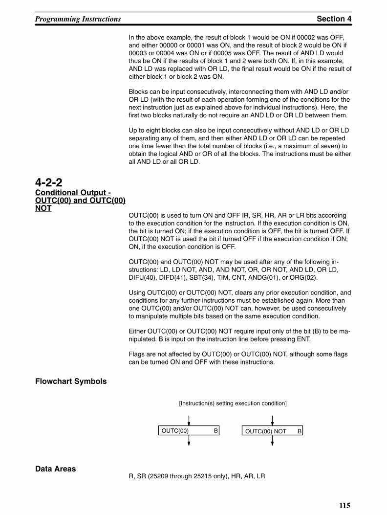
Section 4Programming Instructions
115
In the above example, the result of block 1 would be ON if 00002 was OFF,and either 00000 or 00001 was ON, and the result of block 2 would be ON if00003 or 00004 was ON or if 00005 was OFF. The result of AND LD wouldthus be ON if the results of block 1 and 2 were both ON. If, in this example,AND LD was replaced with OR LD, the final result would be ON if the result ofeither block 1 or block 2 was ON.
Blocks can be input consecutively, interconnecting them with AND LD and/orOR LD (with the result of each operation forming one of the conditions for thenext instruction just as explained above for individual instructions). Here, thefirst two blocks naturally do not require an AND LD or OR LD between them.
Up to eight blocks can also be input consecutively without AND LD or OR LDseparating any of them, and then either AND LD or OR LD can be repeatedone time fewer than the total number of blocks (i.e., a maximum of seven) toobtain the logical AND or OR of all the blocks. The instructions must be eitherall AND LD or all OR LD.
4-2-2Conditional Output -OUTC(00) and OUTC(00)NOT
OUTC(00) is used to turn ON and OFF IR, SR, HR, AR or LR bits accordingto the execution condition for the instruction. If the execution condition is ON,the bit is turned ON; if the execution condition is OFF, the bit is turned OFF. IfOUTC(00) NOT is used the bit if turned OFF if the execution condition if ON;ON, if the execution condition is OFF.
OUTC(00) and OUTC(00) NOT may be used after any of the following in-structions: LD, LD NOT, AND, AND NOT, OR, OR NOT, AND LD, OR LD,DIFU(40), DIFD(41), SBT(34), TIM, CNT, ANDG(01), or ORG(02).
Using OUTC(00) or OUTC(00) NOT, clears any prior execution condition, andconditions for any further instructions must be established again. More thanone OUTC(00) and/or OUTC(00) NOT can, however, be used consecutivelyto manipulate multiple bits based on the same execution condition.
Either OUTC(00) or OUTC(00) NOT require input only of the bit (B) to be ma-nipulated. B is input on the instruction line before pressing ENT.
Flags are not affected by OUTC(00) or OUTC(00) NOT, although some flagscan be turned ON and OFF with these instructions.
Flowchart Symbols
[Instruction(s) setting execution condition]
OUTC(00) B OUTC(00) NOT B
Data AreasR, SR (25209 through 25215 only), HR, AR, LR
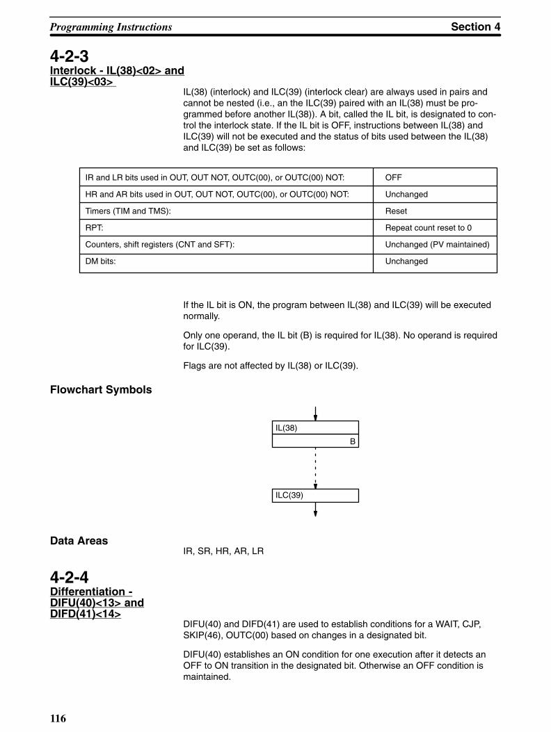
Programming Instructions Section 4
116
4-2-3Interlock - IL(38)<02> andILC(39)<03>
IL(38) (interlock) and ILC(39) (interlock clear) are always used in pairs andcannot be nested (i.e., an the ILC(39) paired with an IL(38) must be pro-grammed before another IL(38)). A bit, called the IL bit, is designated to con-trol the interlock state. If the IL bit is OFF, instructions between IL(38) andILC(39) will not be executed and the status of bits used between the IL(38)and ILC(39) be set as follows:
IR and LR bits used in OUT, OUT NOT, OUTC(00), or OUTC(00) NOT: OFF
HR and AR bits used in OUT, OUT NOT, OUTC(00), or OUTC(00) NOT: Unchanged
Timers (TIM and TMS): Reset
RPT: Repeat count reset to 0
Counters, shift registers (CNT and SFT): Unchanged (PV maintained)
DM bits: Unchanged
If the IL bit is ON, the program between IL(38) and ILC(39) will be executednormally.
Only one operand, the IL bit (B) is required for IL(38). No operand is requiredfor ILC(39).
Flags are not affected by IL(38) or ILC(39).
Flowchart Symbols
IL(38)
B
ILC(39)
Data AreasIR, SR, HR, AR, LR
4-2-4Differentiation -DIFU(40)<13> andDIFD(41)<14>
DIFU(40) and DIFD(41) are used to establish conditions for a WAIT, CJP,SKIP(46), OUTC(00) based on changes in a designated bit.
DIFU(40) establishes an ON condition for one execution after it detects anOFF to ON transition in the designated bit. Otherwise an OFF condition ismaintained.

!
Section 4Programming Instructions
117
DIFD(41) establishes an ON condition for one execution after it detects anON to OFF transition in the designated bit. Otherwise an OFF condition ismaintained.
Each DIFU(40) and DIFD(41) must be assigned a number (N) from 000through 511. This number is input as part of the instruction line, i.e., after thefunction code and before pressing ENT. The same number can be used onlyonce, regardless of whether it is used with DIFU(40) or DIFD(41).
Both DIFU(40) and DIFD(41) require only one operand, the bit (B) that ismonitored to determine the ON/OFF condition established by the instruction.
Caution A change in the bit designated for DIFU(40) or DIFD(41) may not be detected ifmore time is required before the next execution of DIFU(40) or DIFD(41) than thelength of time for which the designated bit is in a changed status. (The status ofthe designated bit is monitored when the DIFU(40) or DIFD(41) is executed andcompared to the status of this bit the last time the same instruction was executed;any changes in the bit in between are ignored if the status at the time of executionremains the same.)
Flowchart Symbol
DIFU(40) N
B
DIFD(41) N
B
Data AreasIR, SR HR, AR, LR
Application Examples• With WAIT
When DIFU(40) is used as the condition for a WAIT, as shown below, execu-tion will stop at the WAIT each time the DIFU(40) is executed until the bit des-ignated for the DIFU(40) (00000 in this example) goes from OFF to ON.
DIFU(40) 000
00000
WAIT
OUT 00500

Programming Instructions Section 4
118
• With CJPIn the following example program section, the NO branch will be taken fromCJP LBL 100 as long as HR 1000 remains in the same status or changesfrom ON to OFF. The first time DIFU(40) 010 is executed after HR 1000 goesfrom OFF to ON, the YES branch will be taken from CJP LBL 100, turning ONoutput 00501.
DIFU(40) 010
HR 1000
CJP LBL 100Yes
No OUT NOT 00501
LBL 0100OUT 00501
• With SKIP(46)Here with a DIFD(41), the NO branch will be taken (skipping two instructions)only the first time after input 00200 goes from ON to OFF, and outputs 00502and 00503 will be turned ON. At all other times, the NO branch will be taken,and these two outputs will be turned ON.
DIFD(41) 100
00200
SKIP NOT
OUT 00502
OUT 00503
OUT 00504
Yes
No
4-2-5No Operation - NOP
When NOP is found in a program, nothing is executed and the next instruc-tion is moved to. When memory is cleared prior to programming, NOP is writ-ten at all addresses. NOP is not normally required in programming, althoughit can be input by pressing DISP CLR and ENT if desired. NOP naturally doesnot require operands and does not affect flags.

!
Section 4Programming Instructions
119
Flowchart Symbol
NOP
4-3Flow Control
The following instructions are used to control basic flow of the program. Moresophisticated flow control can be achieved with Group, Subroutine, and Inter-rupt Control instructions (see 4-12 Group Programs and 4-13 Subroutine andInterrupt Control).
4-3-1WAIT and WAIT NOT
WAIT pauses program execution until the execution condition for it goes ON.WAIT NOT pauses execution until the execution condition for it goes OFF.
WAIT and WAIT NOT are used following LD, AND, OR, AND LD, OR LD,DIFU(40), DIFD(41), TIM, CNT, CNTR<12>, ANDG(01), ORG(02), andSBT(34), or any allowable combination of these in an instruction block(s). Allof the instructions logically relevant to the WAIT or WAIT NOT are repeated ina ‘loop’ until the WAIT or WAIT NOT condition is met.
No operands are required for WAIT, and flags are not affected.
To input WAIT NOT, press WAIT, HR/NOT, and ENT.
Caution If WAIT is used with TIM, CNT, or CNTR<12> and the SV for such produces aBCD or indirect addressing error, the WAIT will not be executed, and programexecution will continue without pausing.
Flowchart Symbol
[Instruction(s) setting condition]
WAIT WAIT NOT
Application ExampleIn the following example, output 00500 is not output until input 00000 is ONand input 00001 is OFF, or until HR 0100 is ON.
AND 00000
AND NOT 00001
OR HR 0100
WAIT
OUT 00500
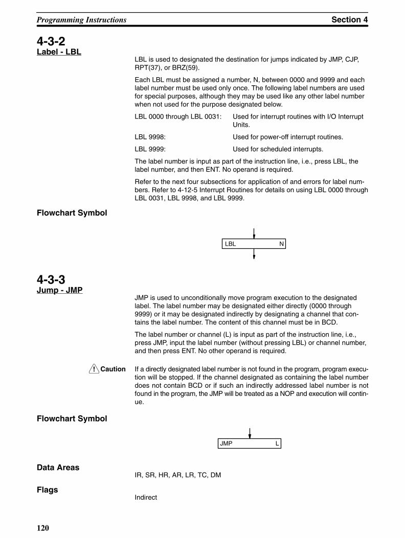
!
Programming Instructions Section 4
120
4-3-2Label - LBL
LBL is used to designated the destination for jumps indicated by JMP, CJP,RPT(37), or BRZ(59).
Each LBL must be assigned a number, N, between 0000 and 9999 and eachlabel number must be used only once. The following label numbers are usedfor special purposes, although they may be used like any other label numberwhen not used for the purpose designated below.
LBL 0000 through LBL 0031: Used for interrupt routines with I/O InterruptUnits.
LBL 9998: Used for power-off interrupt routines.
LBL 9999: Used for scheduled interrupts.
The label number is input as part of the instruction line, i.e., press LBL, thelabel number, and then ENT. No operand is required.
Refer to the next four subsections for application of and errors for label num-bers. Refer to 4-12-5 Interrupt Routines for details on using LBL 0000 throughLBL 0031, LBL 9998, and LBL 9999.
Flowchart Symbol
LBL N
4-3-3Jump - JMP
JMP is used to unconditionally move program execution to the designatedlabel. The label number may be designated either directly (0000 through9999) or it may be designated indirectly by designating a channel that con-tains the label number. The content of this channel must be in BCD.
The label number or channel (L) is input as part of the instruction line, i.e.,press JMP, input the label number (without pressing LBL) or channel number,and then press ENT. No other operand is required.
Caution If a directly designated label number is not found in the program, program execu-tion will be stopped. If the channel designated as containing the label numberdoes not contain BCD or if such an indirectly addressed label number is notfound in the program, the JMP will be treated as a NOP and execution will contin-ue.
Flowchart Symbol
JMP L
Data AreasIR, SR, HR, AR, LR, TC, DM
Flags Indirect

!
Section 4Programming Instructions
121
Jump Error(25309) Channel containing label number is not in BCD.
Label designated by indirect addressing channel is not in program.
ER Channel containing label number is not in BCD.Indirectly addressed DM channel is non-existent.(DM data is not in BCD or the DM area has been exceeded.)
Application ExampleThe following example shows the use of an indirect DM address to accessthe DM channel that contains the label number. Here the content of DM 0002would designate a channel that contains 0020, returning the program as indi-cated so that instructions following LBL 0020 would be executed next.
LBL 0020
JMP *DM 0002
4-3-4Conditional Jump -CJP and CJP NOT
CJP and CJP NOT are used to change the flow of a program according to theexecution condition.
CJP moves program execution to the designated label number if the preced-ing condition is ON, and to the instruction immediately following CJP if thepreceding condition is OFF.
CJP NOT moves program execution to the designated label number if thepreceding condition is OFF, and to the instruction immediately following CJPif the preceding condition is ON.
“YES” and “NO” in the flowchart always indicate that the CJP or CJP NOTcondition is met, i.e., YES is ON for CJP; OFF for CJP NOT.
CJP and CJP NOT are always used after one or more of the following instruc-tions: LD, AND, OR, AND LD, OR LD, DIFU(40), DIFD(41), TIM , CNT,CNTR<12>, ANDG(01), ORG(02), and SBT(34).
The label number may be designated either directly (0000 through 9999) or itmay be designated indirectly by designating a channel that contains the labelnumber. The content of this channel must be in BCD.
The label number or channel (L) is input as part of the instruction line, i.e.,press CJP (and NOT, if required), input the label number (without pressingLBL) or channel number, and then press ENT.
Caution If a directly designated label number is not found in the program, program execu-tion will be stopped. If channel designated as containing the label number doesnot contain BCD or if such an indirectly addressed label number is not found inthe program, the CJP will be treated as a NOP and execution will continue. If CJP is used with TIM, CNT, or CNTR<12> and the SV for such produces a BCDor indirect addressing error, the CJP will be treated as a NOP and execution willcontinue.

Programming Instructions Section 4
122
Flowchart Symbol
CJP NOT LYes
No
Yes
No
[Preceding ON/OFF condition] [Preceding ON/OFF condition]
To designated LBL To designated LBL
CJP L
Data AreasIR, SR, HR, AR, LR, TC, DM
Flags IndirectJump Error(25309) Channel containing label number is not in BCD.
Label designated by indirect addressing channel is not in program.ER Channel containing label number is not in BCD.
Indirectly addressed DM channel is non-existent.(DM data is not in BCD or the DM area has been exceeded.)
Application ExampleIn the following example, LBL 0100 will be jumped to and output 00500 willbe turned ON when input 00000 is ON and input 00001 is OFF; otherwiseoutput 00500 will be turned OFF.
After LBL 0100 is jumped to and output 00500 is turned ON, LBL 0000 (notshown) will be jumped to if input 00002 is OFF or the step following CJP NOTLBL 0 (not shown) will be executed if input 00002 is ON.
OUT NOT 00500
CJP NOT LBL 0
LBL 0100
OUT 00500
AND 00000
AND NOT 00001
CJP LBL 100Yes
No
AND 00002
Yes
No
4-3-5Repeat - RPT(37)
RPT(37) is used to return to a LBL and repeat the instructions between theLBL and RPT(37) a specified number of times before proceeding to the in-struction following RPT.

!
Section 4Programming Instructions
123
The label number may be designated either directly (0000 through 9999) or itmay be designated indirectly by designating a channel that contains the labelnumber. The content of this channel must be BCD.
The label number or channel (L) is input as part of the instruction line, i.e.,press FUN, 3, 7 , input the label number (without pressing LBL) or channelnumber, and then press ENT.
Nesting RPT(37) is not allowed, i.e., there must not be any other RPT(37) ora LBL used for another RPT(37) between the RPT(37) and the LBL beingreturned to.
The number of repetitions (R) must be 99 or fewer and is input either directlyas a constant or indirectly as the content of a designated channel. Includingthe first execution, the designated program section will be repeated one moretime than R, or R + 1 repetitions. R must be designated in BCD.
Caution If a directly designated label number is not found in the program, program execu-tion will be stopped. If channel designated as containing the label number doesnot contain BCD or if such an indirectly addressed label number is not found inthe program, the RPT(37) will be treated as a NOP and execution will continue.
Flowchart Symbol
RPT(37) L
R
Data AreasIR, SR, HR, AR, LR, TC, DM
Flags IndirectJump Error(25309) Channel containing label number is not in BCD.
Label designated by indirect addressing channel is not in program.Number of repetitions exceeds 99.
ER Channel containing label number or number of repetitions is not inBCD.Indirectly addressed DM channel is non-existent.(DM data is not in BCD or the DM area has been exceeded.)
Interlock HandlingIf RPT(37) is found between and IL(38)-ILC(39) pair and the interlock condi-tion is met, the number of repetitions will automatically be set to zero and theinstruction following RPT(37) will be executed without repeating.
Power InterruptionsThe number of repetitions for any RPT(37) used in the main program will bereset when program execution is restarted after a power interruption, and ex-ecution of the main program will be restarted from address 00000.
If the RPT(37) is found in a group program and GC(16) is used (see 4-11-3Group Continue - GC(16)), execution following a power interruption will con-tinue from the instruction being executed when power was interrupted and, it

!
Programming Instructions Section 4
124
a RPT(37) was being executed, the designated number of repetitions will becompleted properly. The designated number of repetitions will also be com-pleted when pauses, jumps to other group programs, or interrupt processingoccurs during RPT(37) execution.
If GC(16) is not used, the number of repetitions for any RPT(37) in a groupprogram will be cleared.
4-3-6Conditional Skip -SKIP(46) and SKIP(46)NOT
SKIP(46) and SKIP(46) NOT are used to change the flow of a program ac-cording to the execution condition.
SKIP(46) moves program execution to the instruction immediately after thedesignated number of instructions (i.e., skips these instructions) if the preced-ing condition is ON, and to the instruction immediately following SKIP(46) ifthe preceding condition is OFF.
SKIP(46) NOT moves program execution to the instruction immediately afterthe designated number of instructions if the preceding condition is OFF, andto the instruction immediately following SKIP(46) if the preceding condition isON.
“YES” and “NO” in the flowchart always indicate that the SKIP(46) orSKIP(46) NOT condition is met, i.e., YES is ON for SKIP(46); OFF forSKIP(46) NOT.
The number of instructions to be skipped, N, must be between 1 and 9, inclu-sive, and it must be input directly as a constant and as part of the instructionline, i.e., press FUN, 4, 6 (and then NOT if required), input the number ofsteps, and then press ENT. No other operand is required and flags are notaffected.
SKIP(46) and SKIP(46) NOT are always used after one or more of the follow-ing instructions: LD, AND, OR, AND LD, OR LD, DIFU(40), DIFD(41), TIM ,CNT, CNTR<12>, ANDG(01), ORG(02), and SBT(34).
Caution If SKIP(46) is used with TIM, CNT, or CNTR<12> and the SV for such produces aBCD or indirect addressing error, the SKIP(46) will be treated as a NOP and ex-ecution will continue to the instruction just after SKIP(46).
Flowchart Symbol
SKIP(46) NOT NYes
No
Yes
No
[Instruction(s) establishing condition] [Instruction(s) establishing condition]
To instruction “N”instructions downthe program
To instruction “N”instructions downthe program
SKIP(46) N
4-3-7Branch for Zero -BRZ(59) and BRZ(59)NOT
BRZ(59) and BRZ(59) NOT are used to change the flow of a program accord-ing whether the content of an operand channel (C) is all zeros or not.

!
Section 4Programming Instructions
125
BRZ(59) moves program execution to the designated label (L) if the operandchannel is all zeros, and to the instruction immediately following BRZ(59) ifthe channel contains anything else.
BRZ(59) NOT moves program execution to the instruction immediately follow-ing BRZ(59) if the operand channel is all zeros, and to the designated label ifthe channel contains anything else.
“YES” and “NO” in the flowchart always indicate that the BRZ(59) or BRZ(59)NOT condition is met, i.e., YES is all zeros for BRZ(59); anything other thanall zeros for BRZ(59) NOT.
The label number may be designated either directly (0000 through 9999) or itmay be designated indirectly by designating a channel that contains the labelnumber. The content of this channel must be BCD.
The label number or channel (L) is input as part of the instruction line, i.e.,press FUN, 5, 9 (and NOT if required) , input the label number (without press-ing LBL) or channel number, and then press ENT.
Caution If a directly designated label number is not found in the program, program execu-tion will be stopped. If the channel designated as containing the label numberdoes not contain BCD or if such an indirectly addressed label number is notfound in the program, the BRZ(59) will be treated as a NOP and execution willcontinue.
Flowchart Symbol
BRZ(59) NOT L
C
BRZ(59) L
L
Yes
No
Yes
No
Data AreasIR, SR, HR, AR, LR, TC, DM
Flags IndirectJump Error(25309) Channel containing label number is not in BCD.
Label designated by indirect addressing channel is not in program.ER Channel containing label number is not in BCD.
Indirectly addressed DM channel is non-existent.(DM data is not in BCD or the DM area has been exceeded.)
EQ Operand channel (C) is all zeros.
4-4Timers and Counters
TIM and TMS are decrementing timer instructions which require a timer num-ber and a set value (SV) as the operand. When the specified SV has elapsed,the timer number in the TC area turns ON. TIM is used in combination withconditional instructions, such as WAIT or CJP; TMS is used independently.The SV for either can be designated directly or as the content of a specifiedchannel.
CNT is a decrementing counter instruction and CNTR<12> is a reversiblecounter instruction. CNT requires a counter number, SV, and a count bit;CNTR<12> requires a counter number, SV, and a control channel containingincrement and decrement bits.

!
Programming Instructions Section 4
126
CNR is used to stop timers and counters and reset them to their SV.
The timer/counter number refers to the actual address in the TC area where abit is turned ON at the end of the timer or counter operation. Each numbermust not be used more than once, regardless of whether it is assigned to atimer or counter. TC addresses (i.e., timer/counter numbers) range from TC000 to TC 511.
4-4-1Timer - TIM
TIM 000 through TIM 383 measure in increments of 0.1 second from a setvalue (SV) between 0 and 999.9 seconds with an accuracy of +0/–0.1 sec-ond. TIM 384 through TIM 511 measure in increments of 0.01 second from aset value (SV) between 0 and 99.99 seconds with an accuracy of +0/–0.01second.
TIM must be used just before WAIT, CJP, SKIP(46), or OUTC(00). A TC areabit assigned to TIM can be used as the operand for another instruction. It canbe designated either as a bit, indicating the ON/OFF status of the timer, or asa channel, indicating the PV (present value) of the timer.
A TIM timer is started from its SV when executed, and the TC area bit isturned ON when the timer’s present value reaches zero. In other words, theconditional instruction used in combination with TIM is executed for an OFFcondition until time expires, when it is executed for an ON condition.
The SV for a TIM must be in BCD and can be input directly as a constant be-tween 0000 and 9999, or it can be designated as the content of a specifiedchannel. To specify a channel, input */CH before inputting the channel num-ber. The specified channel can be used to input the SV through an Input Unitto produce an externally set, variable timer. #/OUT need not be pressed be-fore an SV input as a constant.
When a TIM is first executed, it produces an OFF condition for the followinginstruction. This condition is maintained each time the TIM is executed whilethe timer is operating. When time has expired, an ON condition is created forthe following instruction. If the TIM is again executed, it will be reset to its SVand start operating again.
The timer number refers to an actual address in the TC area. Since this areais also shared by counters, the same number must not be used twice, regard-less of whether it is used for a timer or for a counter. Timer/counter numbersextend from 000 through 511. The timer number is input as part of the instruc-tion line, i.e. press TIM, input the timer number, and then press ENT. The onlyrequired operand is the SV.
Caution If ER goes ON while a timer is operating, the next WAIT, CJP or SKIP(46) will beexecuted as a NOP.

Section 4Programming Instructions
127
Flowchart Symbol
TIM N
SV
Reset ConditionsTimers between an IL(38)-ILC(39) pair are reset to their SV when the IL(38)condition goes OFF. Timers are also reset if a CNR or GOFF(15) is executedfor them, when power is interrupted, or when the PC mode is changed.
Data AreasIR, HR, AR, LR, DM, #
Flags ER SV is not in BCD.
Indirectly addressed DM channel is non-existent.(DM data is not in BCD, or the DM area has been exceeded.)
Application ExamplesThe operation of timers with WAIT and OUTC(00) is reasonable straight for-ward. The following examples show TIM with CJP and SKIP(46). In the firstexample, output 00501 is turned ON for 10 seconds and then turned OFFwhen the SV (10 seconds) for TIM 400 expires. The flowchart section wouldlook as follows. Note that if program flow following OUT 00501 returned torestart the timer immediately, output 00501 would be turned OFF only instan-taneously, being turned ON as soon as the timer was restarted at the nextexecution.
TIM 400
#1000
CJP LBL 100
10 s
OUT NOT 00501
LBL 0100
OUT 00501
Yes
No

Programming Instructions Section 4
128
When combined with SKIP(46) NOT, a program section using TIM would looklike the following.
OUT HR 1000
SVTIM 100
DM 0100
SKIP NOT 2
OUT 00502
OUT 00503
Yes
No
DM 0100
0 1 5 5 15.5 s
Here, outputs 00502 and 00503 would be turned ON only after the timer’s SV(15.5 seconds) had expired. Up until that point, only HR 1000 would beturned ON.
4-4-2Timer Start - TMS(30)
TMS is used to define and start a timer in the TC area by designating a timernumber (TIM 000 through TIM 511) and set value.
TMS 000 through TMS 383 measure in increments of 0.1 second for a setvalue (SV) between 0 and 999.9 seconds with an accuracy of +0/–0.1 sec-ond. TMS 384 through TMS 511 measure in increments of 0.01 second for aset value (SV) between 0 and 99.99 seconds with an accuracy of +0/–0.01second.
TMS differs from TIM in that TMS is used independently and can be followedby any instruction. The next instruction is executed immediately after the tim-er set by TMS is started. A timer number used for TMS can be programmedas the operand for another instruction. It can be designated either as a bit,indicating the ON/OFF status of the timer, or as a channel, indicating the PV(present value) of the timer.
A TMS timer is started from its SV when executed, and the TC area bit isturned ON when the timer’s present value reaches zero. If a TMS is executedduring the countdown operation, it will be reset to its SV and started again.
The SV for a TMS must be in BCD and can be input directly as a constantbetween 0000 and 9999, or it can be designated as the content of a specifiedchannel. To specify a channel, input */CH before inputting the channel num-ber. The specified channel can be used to input the SV through an Input Unitto produce an externally set, variable timer. #/OUT need not be pressed be-fore an SV input as a constant.
The timer number is input as part of the instruction line, i.e., press FUN, 3,and 0, input the timer number, and then press ENT. The only required oper-and is the SV.

Section 4Programming Instructions
129
Flowchart Symbol
TMS(30) N
SV
Reset ConditionsTimers between an IL(38)-ILC(39) pair are reset to their SV when the IL(38)condition goes OFF. Timers are also reset if a CNR or GOFF(15) is executedfor them, when power is interrupted, or when the PC mode is changed.
Data AreasIR, HR, AR, LR, DM, #
Flags ER SV is not in BCD.
Indirectly addressed DM channel is non-existent.(DM data is not in BCD, or the DM area has been exceeded.)
Application ExampleTMS can be used with CMP(52) to control program flow as shown below. TheCMP(52) compares the present value of the timer (TMS 100, which is ad-dressed as TIM 100) with 50 seconds (#0500), and the EQ flag is tested withCJP following the CMP(52) to see if 50 seconds has expired. When the 50seconds has expired, EQ (25506) will be activated and 00500 will be turnedON. GR and LE can be used in similar programming.
EQ flag
LBL 0100
OUT 00500No
Yes
TMS(30) 100
#9999
CMP(52)
TIM100
#0500
AND 25506
CJP LBL 100
4-4-3Counter - CNT
CNT is a preset decrementing counter. That is, it decrements its presentcount value (PV) when the count input pulse goes from OFF to ON. Strictlyspeaking, the count input pulse (CP) is counted only when the signal is ONfor any one execution after being OFF for the execution immediately prior.The greater length of the count input pulse cycle in comparison to the instruc-
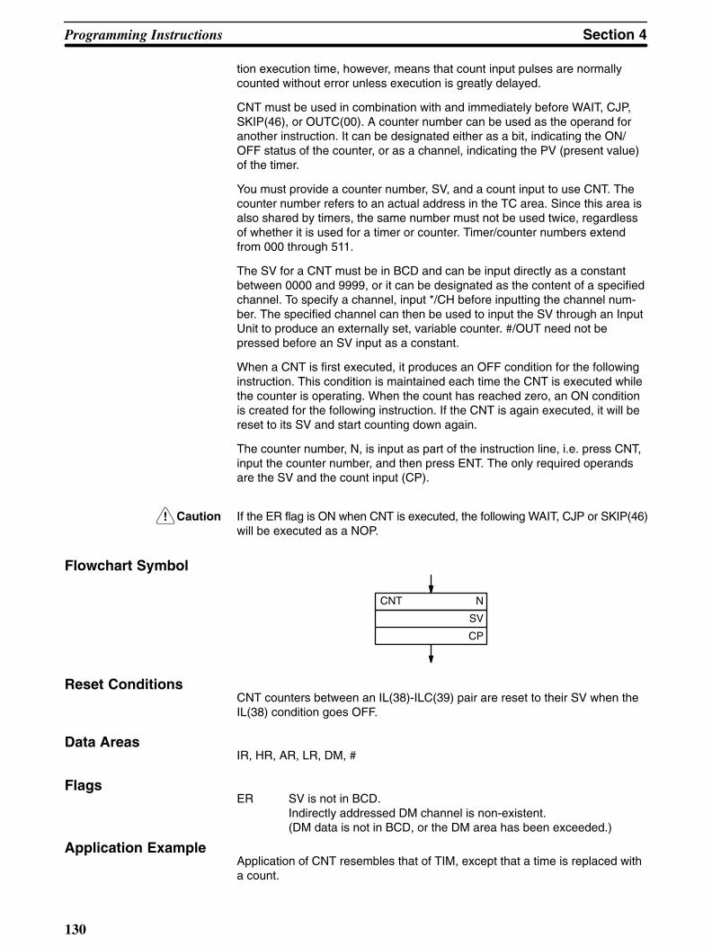
!
Programming Instructions Section 4
130
tion execution time, however, means that count input pulses are normallycounted without error unless execution is greatly delayed.
CNT must be used in combination with and immediately before WAIT, CJP,SKIP(46), or OUTC(00). A counter number can be used as the operand foranother instruction. It can be designated either as a bit, indicating the ON/OFF status of the counter, or as a channel, indicating the PV (present value)of the timer.
You must provide a counter number, SV, and a count input to use CNT. Thecounter number refers to an actual address in the TC area. Since this area isalso shared by timers, the same number must not be used twice, regardlessof whether it is used for a timer or counter. Timer/counter numbers extendfrom 000 through 511.
The SV for a CNT must be in BCD and can be input directly as a constantbetween 0000 and 9999, or it can be designated as the content of a specifiedchannel. To specify a channel, input */CH before inputting the channel num-ber. The specified channel can then be used to input the SV through an InputUnit to produce an externally set, variable counter. #/OUT need not bepressed before an SV input as a constant.
When a CNT is first executed, it produces an OFF condition for the followinginstruction. This condition is maintained each time the CNT is executed whilethe counter is operating. When the count has reached zero, an ON conditionis created for the following instruction. If the CNT is again executed, it will bereset to its SV and start counting down again.
The counter number, N, is input as part of the instruction line, i.e. press CNT,input the counter number, and then press ENT. The only required operandsare the SV and the count input (CP).
Caution If the ER flag is ON when CNT is executed, the following WAIT, CJP or SKIP(46)will be executed as a NOP.
Flowchart Symbol
CNT N
SV
CP
Reset ConditionsCNT counters between an IL(38)-ILC(39) pair are reset to their SV when theIL(38) condition goes OFF.
Data AreasIR, HR, AR, LR, DM, #
Flags ER SV is not in BCD.
Indirectly addressed DM channel is non-existent.(DM data is not in BCD, or the DM area has been exceeded.)
Application ExampleApplication of CNT resembles that of TIM, except that a time is replaced witha count.

!
Section 4Programming Instructions
131
4-4-4Reversible Counter -CNTR <12>
The CNTR<12> is a reversible, up-down circular counter. It increases or de-creases the present value (PV) by one whenever the increment or decrementinput signal goes from OFF to ON. If both the increment and decrement inputsignals are ON at the same time, the PV will not change. The increment sig-nal is bit 15 of a control channel (C) input as the second operand. The decre-ment signal is bit 14. All other control channel bits are ignored.
CNT must be used in combination with and immediately before WAIT, CJP,SKIP(46), or OUTC(00). A counter number can be used as the operand foranother instruction. It can be designated either as a bit, indicating the ON/OFF status of the counter, or as a channel, indicating the PV (present value)of the timer.
Besides the increment and decrement input signals, you must also providethe set value (SV) and a counter number. The set value can be designated asa constant or as the content of a specified channel. The counter number re-fers to an actual address in the TC area. Since this area is also shared bytimers, the same number must not be used twice, regardless of whether thenumber is used for a timer or for a counter. Timer/counter numbers extendfrom 000 through 511.
When decremented from 0000, the present value (PV) is set to SV. Whenincremented past the SV, the PV is set to 0000.
The SV for a CNTR<12> must be in BCD and can be input directly as a con-stant between 0000 and 9999, or it can be designated as the content of aspecified channel. To specify a channel, input */CH before inputting the chan-nel number. The specified channel can then be used to input the SV throughan Input Unit to produce an externally set, variable counter. #/OUT need notbe pressed before an SV input as a constant.
CNTR<12> retains its PV within an IL(38)/ILC(39) loop when the IL(38) condi-tion is OFF.
CNTR<12> counters are reset using CNR.
The counter number, N, is input as part of the instruction line, i.e., pressSHIFT, FUN, 1, and 2, input the counter number, and then press ENT. Theonly required operands are the SV and the control channel (C).
Caution If the ER flag is ON when CNTR<12> is executed, the following WAIT, CJP orSKIP(46) will be executed as a NOP. If a SV designated as the content of a dataarea channel is not in BCD, the counter will operate, but accuracy cannot beguaranteed.
Flowchart Symbol
CNTR(12) N
SV
C
Reset ConditionsCNTR<12> counters between an IL(38)-ILC(39) pair retain their PV while theIL(38) condition is OFF.
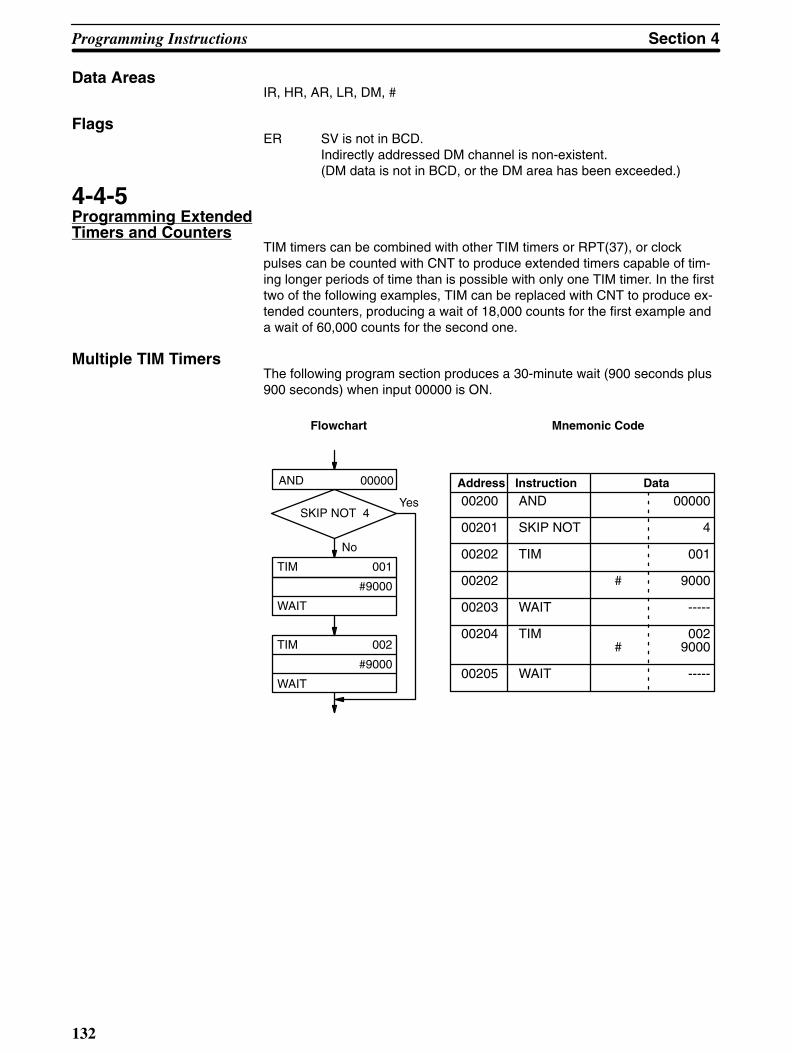
Programming Instructions Section 4
132
Data AreasIR, HR, AR, LR, DM, #
Flags ER SV is not in BCD.
Indirectly addressed DM channel is non-existent.(DM data is not in BCD, or the DM area has been exceeded.)
4-4-5Programming ExtendedTimers and Counters
TIM timers can be combined with other TIM timers or RPT(37), or clockpulses can be counted with CNT to produce extended timers capable of tim-ing longer periods of time than is possible with only one TIM timer. In the firsttwo of the following examples, TIM can be replaced with CNT to produce ex-tended counters, producing a wait of 18,000 counts for the first example anda wait of 60,000 counts for the second one.
Multiple TIM TimersThe following program section produces a 30-minute wait (900 seconds plus900 seconds) when input 00000 is ON.
00200 AND 00000
00201 SKIP NOT 4
00202 TIM 001
00202 # 9000
00203 WAIT -----
00204 TIM 002# 9000
00205 WAIT -----
Yes
No
AND 00000
SKIP NOT 4
TIM 001
#9000
WAIT
TIM 002
#9000
WAIT
Address Instruction Data
Flowchart Mnemonic Code

Section 4Programming Instructions
133
TIM with RPTIn the following program section, output 00501 will go ON 100 minutes (60seconds times 100) after input 00000 goes ON.
00200 AND 00000
00201 WAIT
00202 LBL 0100
00203 TIM 001
# 0600
00204 WAIT -----
00205 RPT LBL 0100
# 0099
00206 OUT 00501
RPT LBL 0100
#0099
AND 00000
WAIT
LBL 0100
TIM 001
#0600
WAIT
OUT 00501
Address Instruction Data
Flowchart Mnemonic Code
Timing with Clock PulsesThe clock pulses provided in the SR area (see 3-3 Special Relay Area - SR)can be counted to produce extended timers as shown below. This programsection will loop for 700 seconds, and then jump to label 200 to turn ON out-put 00503.
00200 AND 00000
00201 WAIT -----
02002 LBL 0100
00203 CNT 002
# 0700
25502
00204 CJP LBL 0200
00205 JMP LBL 0100
:
00250 LBL 0200
00251 OUT 00503
AND 00000
WAIT
LBL 0100
CNT 002
#0700
25501
Yes
No
CJP LBL 200
JMP LBL 100
LBL 0200
OUT 00503
1.0 s clock pulse
Address Instruction Data
Flowchart Mnemonic Code

Programming Instructions Section 4
134
4-4-6Timer/Counter Reset -CNR
CNR is used to reset timer and counters to their SV or to reset other channelsto zero. Timers and counters will not begin operation when reset with CNR.
To reset just one timer or counter, input the timer/counter number (N) as partof the instruction line, i.e., press CNR, TIM or CNT, the timer/counter number,and then ENT.
To reset multiple timers/counters or to reset other channels, input the starting(St) and ending (E) channels as the first and second operands after pressingCNR and ENT. Both the starting and ending channels must be in the samedata area and the starting channel must be less than the end channel.
If the TC data area is designated, all timers/counters between the startingchannel and the end channel will be reset to their SV. Channels designated inany other data area will be reset to zero.
Flowchart Symbol
CNR
St
E
Data AreasTC, IR, HR, AR, LR, DM, *DM
Flags ER The B and E channels are in different areas, or B is greater than E.
Indirectly addressed DM channel is non-existent.(DM data is not in BCD, or the DM area has been exceeded.)
4-4-7Multi-output TimerMTIM(80)
MTIM(80) is an incrementing timer instruction for which up to eight set valuescan be established to turn ON eight corresponding output bits in a resultchannel (R). Channel R is input as the first operand. Bits 00 through 07 of theresult channel are turned ON when the corresponding SV is reached. Bit 08of the result channel serves as the reset input; bit 09, as the timer pause in-put (see below). The remainder of the result channel is not used.
The channel containing the first SV (FSV), which corresponds to bit 00, isdesignated as the third operand. The rest of the SV are contained in theseven channels consecutively following the FSV, with the SV in the last chan-nel (FSV + 7) corresponding to bit 07 in the output channel. If any of theseven channels following FSV contains all zeros, all channels past it will beignored.
SV must be in BCD and are input in increments of 0.1 second, e.g., inputting0155 indicates 15.5 seconds.
The second operand indicates the channel (PVC) to which the PV of the timerwill be output.
When the timer reaches 9999, it will return to 0000 and continue timing, andall outputs in the result channel will turn OFF.

!
Section 4Programming Instructions
135
Caution If a SV is not in BCD, the timer will operate, but accuracy of the outputs corre-sponding to the SV cannot be guaranteed. If MTIM(80) is not executed at leastevery 1.6 seconds, error will result in the PV. SV are compared to the PV andresult channel bits are turned ON only when MTIM(80) is executed. If high preci-sion is required, MTIM(80) must be executed frequently enough so that programexecution time does not affect timing.
Flowchart Symbol
MTIM(80)
R
PVC
FSV
Data AreasIR, HR, AR, LR, DM, *DM
Flags ER R or PVC is not in BCD.
Indirectly addressed DM channel is non-existent.(DM data is not in BCD, or the DM area has been exceeded.)
Resetting and PausingThe MTIM(80) timer can be reset by turning ON bit 08 of the result channeland stopped by turning ON bit 09 of the result channel. These bits can bemanipulated by using OUT or OUT NOT unless the result channel is desig-nated in the DM area. DM area bits can be turned ON by using ORW(66)(with constant 0200 for pausing and 0100 for resetting) and turned OFF byusing ANDW(65) (with constant FDFF for pausing and FEFF for resetting) forthe result channel. See 4-11-3 ORW(66) and 4-11-2 ANDW(65).
If MTIM(80) is executed when bit 09 is ON and bit 08 is OFF, the MTIM(80)will be processed as a NOP. If MTIM(80) is executed when bit 09 is ON, thePV will be reset to 0000, bits 00 through 07 of the result channel will beturned OFF, and the timer will be stopped.
4-5Data Shifting
The instructions described in this section all shift data, but in differingamounts and directions. Each of the shift instructions except for SFT is pro-grammed with a function code.
To input these instructions through the Programming Console, you mustpress FUN followed by the appropriate function code. Data for the operandsalso has to be entered where required.
4-5-1Shift Register - SFT
SFT shifts the status of a designated bit into a shift register defined betweena starting and end channel, and shifts all bits in the shift register by 1 bit, asshown below.
Status of specified bitLost data
End channel Intermediate channels Starting channel

Programming Instructions Section 4
136
Three operands are required: a starting channel (St), an end channel (E), thebit (B) whose status is to be input into the bit 00 of the beginning channel. Stmust be less than or equal to St, and St and E must be in the same dataarea.
Before using using a shift register with SFT, CNR can be used to clear thechannels to zero.
Flowchart Symbol
SFT
B
St
E
Data AreasIR, HR, AR, LR

Section 4Programming Instructions
137
Application ExampleThe following program controls the conveyor line shown below so that faultyproducts detected at the sensor are pushed down a shoot. To do this, inputsfrom the sensor (input 00001) are stored in a shift register: ON for good prod-ucts; OFF for faulty ones. Bit 3 of the shift register is timed to activate thepusher (output 00500) when a faulty product reaches it.
The program is set up to that a rotary encoder (input 00000) controls execu-tion of SFT. Another sensor (input 00002) is used to detect faulty products inthe shoot so that the pusher output and bit 3 of the shift register can be resetas required.
Shoot
0 1 2 3
Sensor
(00001)
Pusher
(00500)
Rotary encoder(00000)
Sensor
(00002)
OUT NOT 00500
OUT NOT HR 0003
Yes
No
Yes
No
LBL 0100
DIFU(40) 000
00000
SKIP NOT 3
SFT
00001
HR 00
HR 00
AND HR 0003
OUTC(00) 00500
LD 00002
SKIP NOT 2
JMP LBL 100
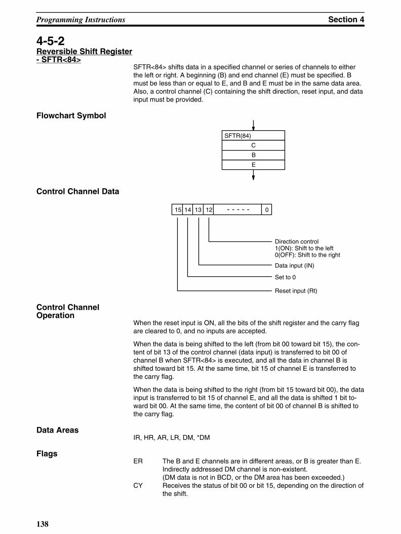
Programming Instructions Section 4
138
4-5-2Reversible Shift Register- SFTR<84>
SFTR<84> shifts data in a specified channel or series of channels to eitherthe left or right. A beginning (B) and end channel (E) must be specified. Bmust be less than or equal to E, and B and E must be in the same data area.Also, a control channel (C) containing the shift direction, reset input, and datainput must be provided.
Flowchart Symbol
C
B
E
SFTR(84)
Control Channel Data
15 14 13 12 0
Direction control 1(ON): Shift to the left0(OFF): Shift to the right
Data input (IN)
Set to 0
Reset input (Rt)
Control Channel Operation
When the reset input is ON, all the bits of the shift register and the carry flagare cleared to 0, and no inputs are accepted.
When the data is being shifted to the left (from bit 00 toward bit 15), the con-tent of bit 13 of the control channel (data input) is transferred to bit 00 ofchannel B when SFTR<84> is executed, and all the data in channel B isshifted toward bit 15. At the same time, bit 15 of channel E is transferred tothe carry flag.
When the data is being shifted to the right (from bit 15 toward bit 00), the datainput is transferred to bit 15 of channel E, and all the data is shifted 1 bit to-ward bit 00. At the same time, the content of bit 00 of channel B is shifted tothe carry flag.
Data AreasIR, HR, AR, LR, DM, *DM
Flags ER The B and E channels are in different areas, or B is greater than E.
Indirectly addressed DM channel is non-existent.(DM data is not in BCD, or the DM area has been exceeded.)
CY Receives the status of bit 00 or bit 15, depending on the direction ofthe shift.
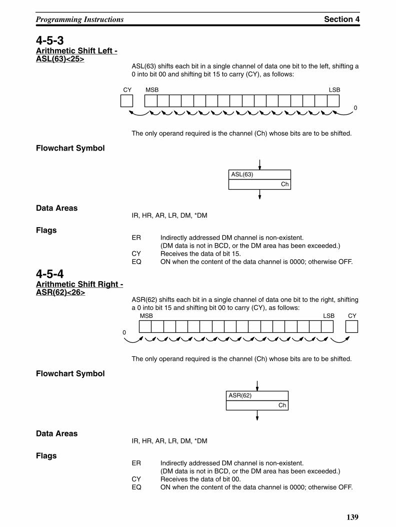
Section 4Programming Instructions
139
4-5-3Arithmetic Shift Left -ASL(63)<25>
ASL(63) shifts each bit in a single channel of data one bit to the left, shifting a0 into bit 00 and shifting bit 15 to carry (CY), as follows:
0
CY MSB LSB
The only operand required is the channel (Ch) whose bits are to be shifted.
Flowchart Symbol
ASL(63)
Ch
Data AreasIR, HR, AR, LR, DM, *DM
Flags ER Indirectly addressed DM channel is non-existent.
(DM data is not in BCD, or the DM area has been exceeded.)CY Receives the data of bit 15.EQ ON when the content of the data channel is 0000; otherwise OFF.
4-5-4Arithmetic Shift Right -ASR(62)<26>
ASR(62) shifts each bit in a single channel of data one bit to the right, shiftinga 0 into bit 15 and shifting bit 00 to carry (CY), as follows:
0
CYMSB LSB
The only operand required is the channel (Ch) whose bits are to be shifted.
Flowchart Symbol
ASR(62)
Ch
Data AreasIR, HR, AR, LR, DM, *DM
Flags ER Indirectly addressed DM channel is non-existent.
(DM data is not in BCD, or the DM area has been exceeded.)CY Receives the data of bit 00.EQ ON when the content of the data channel is 0000; otherwise OFF.

Programming Instructions Section 4
140
4-5-5Rotate Left -ROL(70)<27>
ROL(70) rotates the bits in a single channel of data one bit to the left, withcarry (CY). ROL(70) moves CY into bit 00 of the specified channel, and bit 15into CY as follows:
CYMSB LSB
Use STC(95) or CLC(96) to force-set or force-reset the content of CY as de-sired before doing a rotate operation.
The only operand required is the channel (Ch) whose bits are to be rotated.
Flowchart Symbol
ROL(70)
Ch
Data AreasIR, HR, AR, LR, DM, *DM
Flags ER Indirectly addressed DM channel is non-existent.
(DM data is not in BCD, or the DM area has been exceeded.)CY Receives the data of bit 00.EQ ON when the content of the data channel is 0000; otherwise OFF.
4-5-6Rotate Right -ROR(69)<28>
ROR(69) rotates the bits in a single channel of data one bit to the right, withcarry (CY). ROR(69) moves CY into bit 15 of the specified channel, and bit 00into CY.
CY MSB LSB
Use STC(95) or CLC(96) to force-set or force-reset the content of CY as de-sired before doing a rotate operation.
The only operand required is the channel (Ch) whose bits are to be rotated.

Section 4Programming Instructions
141
Flowchart Symbol
ROR(69)
Ch
Data AreasIR, HR, AR, LR, DM, *DM
Flags ER Indirectly addressed DM channel is non-existent.
(DM data is not in BCD, or the DM area has been exceeded.)CY Receives the data of bit 00.EQ ON when the content of the data channel is 0000; otherwise OFF.
4-5-7One Digit Shift Left -SLD(75)<74>
SLD(75) left shifts data between the starting (St) and end (E) channels byone digit (four bits). SLD writes 0 into the first digit of the beginning channel.The content of the last digit of the end channel is lost.
0
E channel St+1 St channel
E channel St+1 St channel
Lost data
8 F C 5 0 7 82 D 7 9 1
F C 5 0 7 82 D 7 9 1 0
St and E must be in the same data area, and E must be greater than or equalto B.
The only required operands are the starting channel (St) and the end channel(E)
Flowchart Symbol
SLD(75)
St
E
Data AreasIR, HR, AR, LR, DM, *DM
Flags ER The St and E channels are in different areas, or St is greater than
E.Indirectly addressed DM channel is non-existent.(DM data is not in BCD, or the DM area has been exceeded.)

Programming Instructions Section 4
142
4-5-8One Digit Shift Right -SRD(76)<75>
SRD(76) right shifts data between the starting (St) and end (E) channels byone digit (four bits). SRD(76) writes 0 into the left digit of the end channel.The content of the first digit of the beginning channel is lost.
0
E channel St+1 St channel
E channel St+1 St channel
Lost data
3 4 5 2 A 6 21 F 8 C 1
0 3 4 5 2 6A 1 2 F 8 C
St and E must be in the same data area, and E must be greater than or equalto B.
The only required operands are the starting channel (St) and the end channel(E)
Flowchart Symbol
SRD(76)
St
E
Data AreasIR, HR, AR, LR, DM, *DM
Flags ER The St and E channels are in different areas, or St is greater than
E.Indirectly addressed DM channel is non-existent.(DM data is not in BCD, or the DM area has been exceeded.)
4-5-9Word Shift -WSFT(94)<16>
WSFT(94) left shifts data between the starting (St) and end (E) channels inchannel units. The content of a specified channel (Ch) is written into the be-ginning channel and the content of the end channel is lost.
Three operands are required, St, E and Ch.

Section 4Programming Instructions
143
Flowchart Symbol
WSFT(94)
Ch
St
E
Data AreasSt and E
IR, HR, AR, LR, DM, *DM
Ch
IR, SR, HR, AR, LR, TC, DM, *DM
Flags ER The B and E channels are in different areas, or B is greater than E.
Indirectly addressed DM channel is non-existent.(DM data is not in BCD, or the DM area has been exceeded.)
4-6Data Movement
This section describes the instructions used for moving data between dataareas. Data movement is essential for utilizing all of the internal data areas ofthe PC. Communication in linked systems also requires data movement.
Each instruction is programmed with a function code. To input these instruc-tions through the Programming Console, press FUN followed by the appropri-ate function code. Data for the operands also has to be entered where re-quired.
4-6-1Move - MOV(50)<21> andMove Not - MVN(51)<22>
MOV(50) transfers source data (S) (either the data in a specified channel or afour-digit hexadecimal constant) to a destination channel (D) (some specifiedchannel). The source channel is not changed.
MVN(51) inverts the source data and then transfers it to the destination chan-nel. The source channel is not changed.
Timers and counters cannot be designated as destinations of MOV(50) orMVN(51). You can, however, easily change a timer’s PV or a counter’s PV byusing BSET(73).

Programming Instructions Section 4
144
Flowchart Symbols
MOV(50)
S
D
MOV(51)
S
D
Data Areas S
IR, SR, HR, AR, LR, TC, DM, *DM, #
D
IR, HR, AR, LR, DM, *DM
FlagsER Indirectly addressed DM channel is non-existent.
(DM data is not in BCD, or the DM area has been exceeded.)EQ ON when source and destination channel content is 0000; other-
wise OFF.
4-6-2Block Set -BSET(73)<71>
BSET(73) copies the content of one channel or a constant to several consec-utive channels.
Three operands are required: a starting channel (St), an end channel (E), andthe channel or constant (Ch) to be copied. St must be less than or equal to E,and St and E must be in the same data area.
BSET(73) can be used to change timer/counter data. (This cannot be donewith MOV(50) or MVN(51).)
Although BSET(73) can be used to clear consecutive channels to zero, fewerwords will be required to clear channels if CNR is used.
Flowchart Symbols
BSET(73)
Ch
St
E
Data Areas St and E
IR, SR, HR, AR, LR, TC, DM, *DM, #
Ch
IR, HR, AR, LR, TC, DM, *DM
FlagsER The St and E channels are in different areas, or St is greater than
E.Indirectly addressed DM channel is non-existent.(DM data is not in BCD, or the DM area has been exceeded.)

Section 4Programming Instructions
145
Application ExampleThe following program uses BSET(73) to change the PV of a timer. The pro-gram is designed to change the timer to a different PV depending on execu-tion conditions. More specifically, if input 00001 is ON, the timer’s PV will beset to 8 seconds and output 0050 will be made in 8 seconds. If input 00002 isON, the timer’s PV will be set to 5 seconds and output 0050 will be made in 5seconds.
Yes
No
Yes
No
OUT 00500
SKIP NOT 1
SKIP NOT 1
LD 00000
WAIT
TMS(30) 000
#0100
LD 00001
AND NOT 00002
BSET(73)
#0080
TIM 000
TIM 000
LD 00002
AND NOT 00001
BSET(73)
#0050
TIM 000
TIM 000
AND TIM 000
WAIT
4-6-3Block Transfer -XFER(72)<70>
XFER(72) moves the content of several consecutive source channels (S: be-ginning source channel) to consecutive destination channels (D: beginningdestination channel).

Programming Instructions Section 4
146
N, the number of channels to be transferred, must be a four-digit BCD num-ber. Both the source and destination channels must be in the same data area,and their respective blocks must not overlap.
Flowchart Symbol
XFER(72)
N
S
D
Data AreasN
IR, HR, AR, LR, TC, DM, *DM, #
S
IR, HR, AR, LR, TC, DM, *DM
D
IR, SR, HR, AR, LR, TC, DM, *DM, #
Flags ER N is not in BCD, or when added to the source channel, the end ad-
dress lies outside of the data area of the source channel.Indirectly addressed DM channel is non-existent.(DM data is not in BCD, or the DM area has been exceeded.)
4-6-4Move Bit - MOVB<82>
MOVB<82> transfers the designated bit of a designated source channel orconstant (S) to the designated bit of a designated destination channel (D).
The source (S) and destination (D) channels (or source constant) are input asoperands. The specifications for the source and destination bits are both made in the third operand, control data (C). The control data must be in BCD.

Section 4Programming Instructions
147
Flowchart Symbol
MOVB(82)
S
C
D
Control Data
Bit 15 Bit 00
Source bit specification (BCD - 0 to 15)
Destination bit specification (BCD - 0 to 15)
Data Areas S
IR, SR, HR, AR, LR, DM, *DM, #
C
IR, HR, AR, LR, TC, DM, *DM, #
D
IR, HR, AR, LR, DM, *DM
Note: Bits of the source data are handled as individual binary units, re-gardless of whether the channels contain binary or BCD data.
Flags ER Control data is not in BCD, or it is specifying a non-existent bit (i.e.,
bit specification must be between 00 and 15).Indirectly addressed DM channel is non-existent.(DM data is not in BCD, or the DM area has been exceeded.)
4-6-5Move Digit - MOVD<83>
MOVD<83> moves the hexadecimal digit content of the specified four-bitsource digit to the specified destination digit(s). Up to four digits can be trans-ferred at one time.
The source channel or constant (S) and destination channel (D) are input asoperands. The third operand, control data (C), provides the starting sourcedigit, the number of digits to be transferred, and the starting destination digit.

Programming Instructions Section 4
148
Flowchart Symbol
MOVD(83)
S
C
D
Control Data Bit 15 Bit 00
Specifies which source digit (0 to 3) to be moved first
Specifies the first destination digit (0 to 3)
Number of digits to be moved (0 to 3) 0:1 digit (4 bits) 1:2 digits (8 bits) 2:3 digits (12 bits) 3:4 digits (16 bits)
Not used (Set to 0)
Note: The source and destination may involve two channels if the firstdigit is designated high enough and enough digits are designated.
Data Area S
IR, SR, HR, AR, LR, TC, DM, *DM, #
C
IR, HR, AR, LR, TC, DM, *DM, #
D
IR, HR, AR, LR, TC, DM, *DM
FlagsER Control data is specifying a digit that is not 0, 1, 2, or 3.
Indirectly addressed DM channel is non-existent.(DM data is not in BCD, or the DM area has been exceeded.)
Application ExampleThe following example performs floating point division, dividing the four-digitcontent of IR channel 10 by the content of DM 0000 and DM 0001. The resultis placed in HR 20 and HR 21. Here the leftmost digit of the highest channelis used to hold the exponent indicating the decimal place.
1. First, the constant 4000 is transferred to DM 0101 to write the exponentinto the leftmost digit.
2. The leftmost three digits of IR channel 10 are transferred to the right-most three digits of DM 0101.
3. The constant 0000 is transferred to DM 0100 to write zeros into the right-most three digits.
4. The rightmost digit of IR channel 10 is transferred to the leftmost digit ofDM 0100.
5. FDIV<79> is then used to divide the content of DM 0100 and DM 1010by that of DM 0000 and DM 0001, placing the result in HR 20 and HR21.

Section 4Programming Instructions
149
The flowchart and data movements for this operation are as follows (3025 isused as the content of IR channel 10:
MOVD(83)
010
#0021
DM 0101
LD 00000
WAIT
MOV(50)
#4000
DM 0101
MOV(50)
#0000
DM 0100
MOVD(83)
010
#0300
DM 0100
FDIV(79)
DM 0100
DM 0000
HR 20
3 0 2
3 0 2 5
4 0 0 0 0 0 0 0
#0000#4000
DM 0101 DM 0100
Ch 010
5
4 3 0 2 5 0 0 0
DM 0101 DM 0100
4 3 0 2 5 0 0 0
DM 0001 DM 0000=
4 3 0 2 5 0 0 0
HR 21 HR 20
104 × 0.3025
4-6-6Data Exchange -XCHG(74)<73>
XCHG(74) exchanges the contents of two different channels (E1 and E2).
If you want to exchange contents between 2 blocks whose size is greaterthan 1 channel, use another data area as an intermediate buffer and transferdata to that area with the block transfer XFER(72) instruction.

Programming Instructions Section 4
150
Flowchart Symbol
XCHG(74)
D1
D2
Data Areas IR, HR, AR, LR, TC, DM, *DM
FlagsER Indirectly addressed DM channel is non-existent.
(DM data is not in BCD, or the DM area has been exceeded.)
4-6-7Single ChannelDistribution - DIST<80>
DIST<80> moves one channel of source data (S) to a destination channelwhose address is given by a destination base channel (DBs) plus an offset(Of). That is, the offset is added to the destination base channel to determinethe actual destination channel.
The offset data must be a four-digit BCD value. Also, the final destination ad-dress must be in the same data area as the destination base channel.
Flowchart Symbol
DIST(80)
S
Bs
Of
Data AreasS
IR, SR, HR, AR, LR, TC, DM, *DM, #
DBs
IR, HR, AR, LR, TC, DM, *DM
Of
IR, HR, AR, LR, TC, DM, *DM, #
Flags ER The specified offset data is not in BCD, or final destination channel
lies outside the data area of the destination base channel.Indirectly addressed DM channel is non-existent.(DM data is not in BCD, or the DM area has been exceeded.)
EQ ON when source channel content is 0000; otherwise OFF.
Application ExampleIn the following example, INC(60) is used to increment HR 10, the offset forDIST(80). DIST(80) places lengths (input to IR channel 10) measured on aconveyor belt, with the objects being detected by a photocell (input 00000).

Section 4Programming Instructions
151
Each time input 00000 comes ON, a length from IR channel 10 is placed inthe next DM channel, which starts at DM 0100, the destination base forDIST(80). This is repeated until 100 lengths have been stored. The flowchartand basic setup for this process are as follows:
RPT LBL 100
#0099
MOV(50)
#0000
HR 10
LBL 0100
DIFU(40) 200
00000
WAIT
DIST(80)
010
DM 0100
HR 10
INC(60)
HR 10
DM0198
DM0104
DM0103
DM0102
DM0101
DM0199
DM0100
0098
0004
0003
0002
0001
0099
0000
Ch 010
HR 10
VDM Ch 010
Ph 00000
4-6-8Data Collection -COLL<81>
COLL<81> extracts data from the source channel and writes it to a destina-tion channel (D). The address of the source channel is determined by addingan offset (Of) to the source base channel (SBs).
The offset data must be a four-digit BCD value. Also, the source channelmust be in the same data area as the source base channel.
Flowchart Symbol
COLL(81)
Bs
Of
D
Data Areas SBs

Programming Instructions Section 4
152
IR, SR, HR, AR, LR, TC, DM, *DM, #
Of
IR, HR, AR, LR, TC, DM, *DM, #
D
IR, HR, AR, LR, TC, DM, *DM
FlagsER The specified offset data is not in BCD, or the source base channel
lies outside of the data area of the source channel.Indirectly addressed DM channel is non-existent.(DM data is not in BCD, or the DM area has been exceeded.)
EQ ON when source channel content is 0000.
4-7Data Comparison
This section describes the instructions used for comparing data. Direct com-parisons for equality are possible as well as range checks.
Each data comparison instruction is programmed with a function code. Toinput these instructions through the Programming Console, press FUN fol-lowed by the appropriate function code.
4-7-1Compare - CMP(52)<20>
CMP(52) compares two sets of four-digit hexadecimal data (C1 and C2) andoutputs the result to the GR, EQ, and LE flags in the SR area. (Refer to3-3-10 Arithmetic Operation Flags.)
When comparing a constant to the PV of a timer or counter, the constantmust be a four-digit BCD value.
Flowchart Symbol
CMP(52)
C1
C2
Data AreasIR, SR, HR, AR, LR, TC, DM, *DM, #
Flags ER Indirectly addressed DM channel is non-existent.
(DM data is not in BCD, or the DM area has been exceeded.)EQ ON only if C1 equals C2.LE ON only if C2 is less than C1.GR ON only if C2 is greater than C1.Note: Placing other instructions between CMP(52) and accessing the EQ,
LE, and GR flags may change the status of these flags. Be sure toaccess them before the desired status is changed.

Section 4Programming Instructions
153
Application ExampleThe following example uses a timer, CMP(52), and the LE flag to produceoutputs at particular points in the countdown. Output 00200 is output after100 seconds; output 00201, after 200 seconds; output 00202, after 300 sec-onds; and output 00204, after 500 seconds.
Output at 300 s.
Yes
No
Output at 500 s.
Output at 100 s.
Output at 200 s.
AND 00000
WAIT
LBL 0100
TIM 010
#5000
CJP LBL 700
CMP(52)
TIM 010
#4000
AND 25506
OUTC 00200
CMP(52)
TIM 010
#3000
AND 25506
OUTC 00201
CMP(52)
TIM 010
#2000
AND 25506
OUTC 00202
JMP LBL 0100
LBL 0700
OUT 00204

Programming Instructions Section 4
154
4-7-2Compare Long-CMPL<60>
CMPL<60> compares two sets of eight-digit hexadecimal data (C1 and C2)and outputs the result to the GR, EQ, and LE flags in the SR area. (Refer to3-3-10 Arithmetic Operation Flags.)
Two operands are required: the first channel of each of the two sets of chan-nels that are to be compared (C1 and C2). The first channel holds the right-most bits of the eight-digit value.
Flowchart Symbol
CMPL(60)
C1
C2
Data AreasIR, SR, HR, AR, LR, TC, DM, *DM, #
Flags ER Indirectly addressed DM channel is non-existent.
(DM data is not in BCD, or the DM area has been exceeded.)EQ ON only if the two hexadecimal values are equal.LE ON only if the second hexadecimal value (C2) is less than the first
(C1).GR ON only if the second hexadecimal value (C2) is greater than the
first (C1).Note: Placing other instructions between CMP(52) and accessing the EQ,
LE, and GR flags may change the status of these flags. Be sure toaccess them before the desired status is changed.
4-7-3Block Compare -BCMP<68>
BCMP<68> takes a 1-channel binary value (CD) and compares it with 16ranges in a comparison table (CB: First channel of the comparison table). Ifthe value falls within any of the ranges, BCMP<68> sets corresponding bits ofthe specified result channel (R).
The comparison table consists of 32 channels, with every two consecutivechannels indicating a range. Beginning with channel CB, for each of the 16ranges in the comparison table, the first of the two channels contains the low-er limit value and the second channel, the upper limit value. The BCMP<68>operation thus involves the comparison of a 16-bit value with the lower limit16-bit value and the higher limit 16-bit value of each range in the comparisontable. If, for example, CB ≤ CD ≤ CB+1, bit 0 of the result channel to indicatethat the comparison data lies within the first range.
The first channel of the comparison table must be set so that the entire tableis contained in one data area.
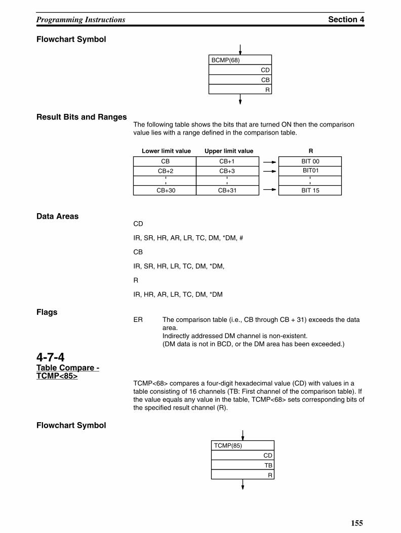
Section 4Programming Instructions
155
Flowchart Symbol
BCMP(68)
CD
CB
R
Result Bits and RangesThe following table shows the bits that are turned ON then the comparisonvalue lies with a range defined in the comparison table.
Upper limit valueLower limit value
CB
CB+2
CB+30
CB+3
CB+31
CB+1 BIT 00
BIT01
BIT 15
R
Data AreasCD
IR, SR, HR, AR, LR, TC, DM, *DM, #
CB
IR, SR, HR, LR, TC, DM, *DM,
R
IR, HR, AR, LR, TC, DM, *DM
Flags ER The comparison table (i.e., CB through CB + 31) exceeds the data
area.Indirectly addressed DM channel is non-existent.(DM data is not in BCD, or the DM area has been exceeded.)
4-7-4Table Compare -TCMP<85>
TCMP<68> compares a four-digit hexadecimal value (CD) with values in atable consisting of 16 channels (TB: First channel of the comparison table). Ifthe value equals any value in the table, TCMP<68> sets corresponding bits ofthe specified result channel (R).
Flowchart Symbol
TCMP(85)
CD
TB
R
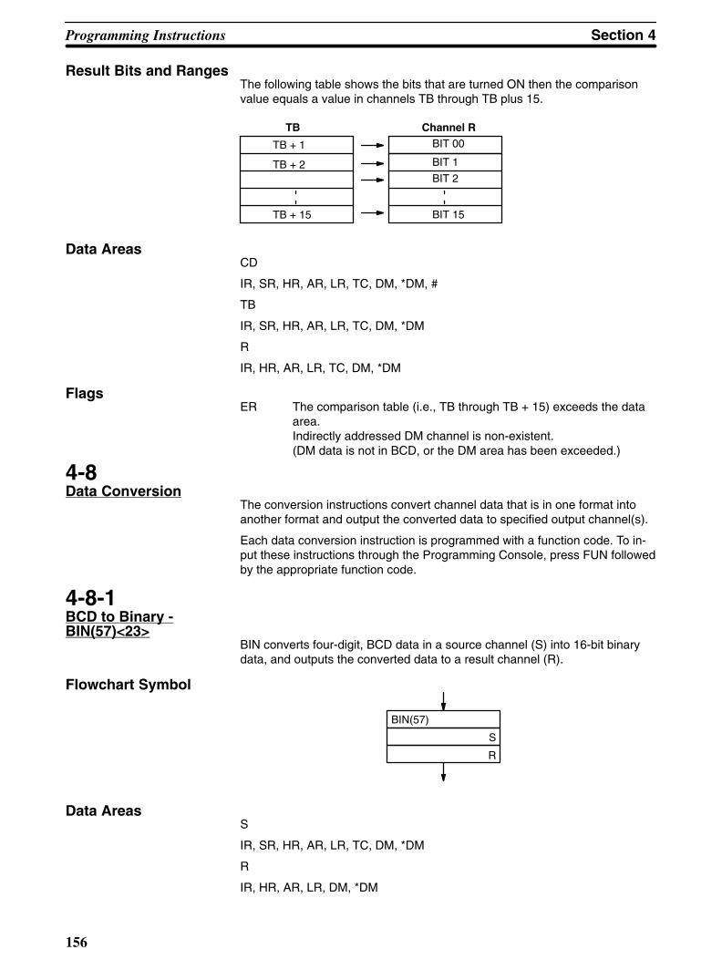
Programming Instructions Section 4
156
Result Bits and RangesThe following table shows the bits that are turned ON then the comparisonvalue equals a value in channels TB through TB plus 15.
BIT 1
BIT 2
BIT 15
TBBIT 00TB + 1
TB + 2
TB + 15
Channel R
Data AreasCD
IR, SR, HR, AR, LR, TC, DM, *DM, #
TB
IR, SR, HR, AR, LR, TC, DM, *DM
R
IR, HR, AR, LR, TC, DM, *DM
FlagsER The comparison table (i.e., TB through TB + 15) exceeds the data
area.Indirectly addressed DM channel is non-existent.(DM data is not in BCD, or the DM area has been exceeded.)
4-8Data Conversion
The conversion instructions convert channel data that is in one format intoanother format and output the converted data to specified output channel(s).
Each data conversion instruction is programmed with a function code. To in-put these instructions through the Programming Console, press FUN followedby the appropriate function code.
4-8-1BCD to Binary -BIN(57)<23>
BIN converts four-digit, BCD data in a source channel (S) into 16-bit binarydata, and outputs the converted data to a result channel (R).
Flowchart Symbol
BIN(57)
S
R
Data AreasS
IR, SR, HR, AR, LR, TC, DM, *DM
R
IR, HR, AR, LR, DM, *DM

Section 4Programming Instructions
157
Flags ER The content of the source channel is not in BCD.
Indirectly addressed DM channel is non-existent.(DM data is not in BCD, or the DM area has been exceeded.)
EQ ON when the content of the result channel is 0000.
4-8-2BCD to Double Binary -BINL<58>
BINL<58> (double-length BIN) converts an eight-digit BCD value in twosource channels into 32-bit binary data and outputs the converted data to tworesult channels.
Two operands are required: the lower (rightmost) of the two source channels(S) and that of the two result channels (R).
Flowchart Symbol
BINL(58)
S
R
Data AreasS
IR, SR, HR, AR, LR, TC, DM, *DM
R
IR, HR, AR, LR, DM, *DM
Flags ER Content of the S and/or S+1 channel is not in BCD.
Indirectly addressed DM channel is non-existent.(DM data is not in BCD, or the DM area has been exceeded.)
EQ ON when content of the result channels is 0000 0000.
4-8-3Binary to BCD -BCD(58)<24>
The BCD(58) (binary-to-BCD conversion) instruction converts 16-bit binarydata in a source channel (S) into four-digit, BCD data, and outputs the con-verted data to a result channel (R).
If the content of the source channel exceeds “270F,” the converted resultwould exceed “9999” and the instruction will not be executed. When the in-struction is not executed, R remains unchanged.
Flowchart Symbol
BCD(58)
S
R

Programming Instructions Section 4
158
Data AreasS
IR, SR, HR, AR, LR, DM, *DM
R
IR, HR, AR, LR, DM, *DM
Flags ER Result channel overflow (i.e, content of R is greater than 9999).
Indirectly addressed DM channel is non-existent.(DM data is not in BCD, or the DM area has been exceeded.)
EQ ON when the content of the result channel is 0000.
4-8-4Double Binary to DoubleBCD - BCDL<59>
BCDL<59> (double-length BCD) converts 32-bit binary data in two sourcechannels into eight digits of BCD data, and outputs the converted data to tworesult channels.
Two operands are required: the lower (rightmost) of the two source channels(S) and that of the two result channels (R).
If the content of the source channels exceeds “05F5 E0FF,” the convertedresult will exceed “9999 9999” and the instruction will not be executed. Whenthe instruction is not executed, R and R+1 remain unchanged.
Flowchart Symbol
BCDL(59)
S
R
Data AreasS
IR, SR, HR, AR, LR, TC, DM, *DM
R
IR, HR, AR, LR, DM, *DM
Flags ER Result channels, R and R+1, overflow (i.e, content of R and R+1
exceeds 99999 99999).Indirectly addressed DM channel is non-existent.(DM data is not in BCD, or the DM area has been exceeded.)
EQ ON when the content of the result channels is 0000 0000.
4-8-54 to 16 Decoder -MLPX(77)<76>
MLPX(77) converts up to four, four-bit hexadecimal digits in the source chan-nel (S) into decimal values from 0 to 15 and then turns ON in the result chan-nel(s) the bit(s) whose bit number(s) corresponds to the converted value. Ifmore than one source digit is specified, then one bit will be turned ON foreach in consecutive channels following the designated beginning result chan-nel (RB).

Section 4Programming Instructions
159
The first digit and the number of digits to be converted are designated in thesecond operand (Di). If more digits are designated than remain in the channel(counting from the designated first digit), the remaining digits will be takenstarting back at the beginning of the source channel.
The final channel required to store the converted result (RB plus the numberof digits to be converted) must be in the same data area as the designatedfirst result channel.
Flowchart Symbol
MLPX(77)
S
Di
RB
Digit Designator Bit 15 Bit 00
Specifies the first digit to be converted (0 to 3)
Number of digits to be converted (0 to 3) 0:1 digit (4 bits) 1:2 digits (8 bits) 2:3 digits (12 bits) 3:4 digits (16 bits)
Not used (Set to 00)
Data AreasS
IR, SR, HR, AR, LR, TC, DM, *DM
Di
IR, HR, AR, LR, TC, DM, *DM, #
RB
IR, HR, AR, LR, DM, *DM
FlagsER Incorrect digit designator, or RB plus number of digits exceeds the
data area.Indirectly addressed DM channel is non-existent.(DM data is not in BCD, or the DM area has been exceeded.)
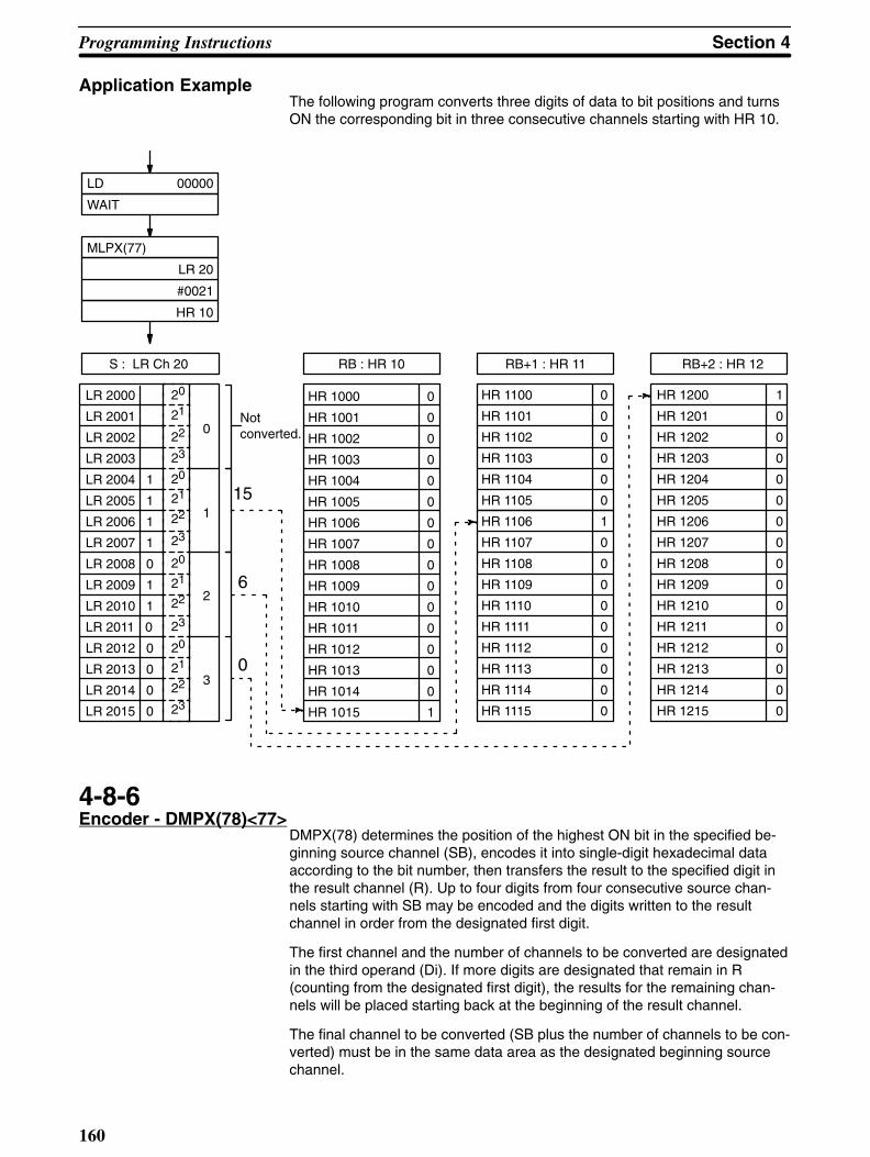
Programming Instructions Section 4
160
Application ExampleThe following program converts three digits of data to bit positions and turnsON the corresponding bit in three consecutive channels starting with HR 10.
MLPX(77)
LR 20
#0021
HR 10
LD 00000
WAIT
HR 1200 1
HR 1201 0
HR 1202 0
HR 1203 0
HR 1204 0
HR 1205 0
HR 1206 0
HR 1207 0
HR 1208 0
HR 1209 0
HR 1210 0
HR 1211 0
HR 1212 0
HR 1213 0
HR 1214 0
HR 1215 0
LR 2000
LR 2001
LR 2002
LR 2003
LR 2004 1
LR 2005 1
LR 2006 1
LR 2007 1
LR 2008 0
LR 2009 1
LR 2010 1
LR 2011 0
LR 2012 0
LR 2013 0
LR 2014 0
LR 2015 0
HR 1000 0
HR 1001 0
HR 1002 0
HR 1003 0
HR 1004 0
HR 1005 0
HR 1006 0
HR 1007 0
HR 1008 0
HR 1009 0
HR 1010 0
HR 1011 0
HR 1012 0
HR 1013 0
HR 1014 0
HR 1015 1
HR 1100 0
HR 1101 0
HR 1102 0
HR 1103 0
HR 1104 0
HR 1105 0
HR 1106 1
HR 1107 0
HR 1108 0
HR 1109 0
HR 1110 0
HR 1111 0
HR 1112 0
HR 1113 0
HR 1114 0
HR 1115 0
20
21
22
23
20
21
22
23
20
21
22
23
20
21
22
23
0
1
2
3
Not converted.
15
6
0
S : LR Ch 20 RB : HR 10 RB+1 : HR 11 RB+2 : HR 12
4-8-6Encoder - DMPX(78)<77>
DMPX(78) determines the position of the highest ON bit in the specified be-ginning source channel (SB), encodes it into single-digit hexadecimal dataaccording to the bit number, then transfers the result to the specified digit inthe result channel (R). Up to four digits from four consecutive source chan-nels starting with SB may be encoded and the digits written to the resultchannel in order from the designated first digit.
The first channel and the number of channels to be converted are designatedin the third operand (Di). If more digits are designated that remain in R(counting from the designated first digit), the results for the remaining chan-nels will be placed starting back at the beginning of the result channel.
The final channel to be converted (SB plus the number of channels to be con-verted) must be in the same data area as the designated beginning sourcechannel.

Section 4Programming Instructions
161
Flowchart Symbol
DMPX(78)
S
R
Di
Data Areas
SB
IR, SR, HR, AR, LR, TC, DM, *DM,
R
IR, HR, AR, LR, DM, *DM,
Di
IR, HR, AR, LR, TC, DM, *DM, #
Flags ER Incorrect digit designator data, or SB plus the number of channels
exceeds a data area.Indirectly addressed DM channel is non-existent.(DM data is not in BCD, or the DM area has been exceeded.)Content of an source input channel (SB, SB+1, SB+2, or SB+3) is0000.

Programming Instructions Section 4
162
Application ExampleThe following program encodes IR channels 10 and 11 to the first two digitsof HR 20 and then encodes LR 10 and 11 to the last two digits of HR 20.
LR 1000
LR 1001 1
LR 1002 0
LR 1015 0
DMPX(78)
010
HR 20
#0010
DMPX(78)
LR 10
HR 20
#0012
DIFU(40) 20
00000
WAIT
LR 1100
LR 1108 1
LR 1109 0
LR 1115 0
01000
01011 1
01012 0
01015 0
01100
01109 1
01110 0
01115 0
LR 20B
9
1
8
0 digit
1 digit
2 digit
3 digit
Ch 010 Ch 011
LR 11LR 10
4-8-7Seven-Segment Decoder- SDEC(79)<78>
SDEC(79) converts up to four digits of hexadecimal values from a sourcechannel (S) to eight-bit data for seven-segment display output. The result isoutput to consecutive half channels starting at the leftmost or rightmost half ofthe beginning destination channel (DB).

Section 4Programming Instructions
163
The first digit to be converted, the number of digits to be converted, and thehalf of the beginning destination channel to receive the first result are desig-nated in the second operand, the digit designator (Di)
The specified destination channel plus the number of channels required tostore the result must be in the same data area as the beginning destinationchannel.
Flowchart Symbol
SDEC(79)
S
Di
DB
Digit Designator Bit 15 Bit 00
Specifies the first digit to be converted (0 to 3)
Destination designation “0”: Right most 8 bits “1”: Left most 8 bits
Number of digits to be converted (0 to 3) 0:1 digit (4 bits) 1:2 digits (8 bits) 2:3 digits (12 bits) 3:4 digits (16 bits)
Not used (Set to 0)
Data AreasS
IR, SR, HR, AR, LR, TC, DM, *DM,
Di
IR, HR, AR, LR, TC, DM, *DM, #
DB
IR, HR, AR, LR, DM, *DM
Flags ER Incorrect digit designator, or DB plus the required number of chan-
nels exceeds the data area.Indirectly addressed DM channel is non-existent.(DM data is not in BCD, or the DM area has been exceeded.)

!
Programming Instructions Section 4
164
Application ExampleThe following Di and S data would produce the data required to display an 8as shown.
1: Begin decoding with the second digit of the source channel.
0: Decode onedigit.
0: Transfer the decoded value to the right most 8 bits of the destinationchannel.
This area is not used.
a
b
c
d
e
f
g
Bit 00Bit 001
1
1
1
1
1
1
0
0
0
0
0
0
1
0
1
0
1
1
1
1
0
1
1
20
21
22
23
20
21
22
23
20
21
22
23
20
21
22
23
0
1
2
3
Bit 15Bit 15
×100
0
0
0
0
0
0
0
0
0
0
0
1
×101
×102
×103
Di S DB
Externally wired display
Caution FAL(35) and FALS(36) output error codes to the rightmost eight bits of SR chan-nel 253.
4-8-8ASCII Code Conversion -ASC<86>
ASC<86> converts up to four digits of hexadecimal values from a sourcechannel (S) to eight-bit ASCII code. The result is output to consecutive halfchannels starting at the leftmost or rightmost half of the beginning destinationchannel (DB).
The first digit to be converted, the number of digits to be converted, the half ofthe beginning destination channel to receive the first result, and the parity tobe set are designated in the second operand, the digit designator (Di)
The specified destination channel plus the number of channels required tostore the result must be in the same data area as the beginning destinationchannel.

Section 4Programming Instructions
165
Flowchart Symbol
ASC(86)
S
Di
DB
Digit Designator
Bit 15 Bit 00
Specifies the first digit to be converted (0 to 3)
Destination designation 0: Right most 8 bits 1: Left most 8 bits
Number of digits to be converted (0 to 3) 0:1 digit (4 bits) 1:2 digits (8 bits) 2:3 digits (12 bits) 3:4 digits (16 bits)
Parity designation 0: No parity (always 0) 1: Even parity 2: Odd parity
Data AreasS
IR, SR, HR, AR, LR, TC, DM, *DM,
Di
IR, HR, AR, LR, TC, DM, *DM, #
DB
IR, HR, AR, LR, DM, *DM
Flags ER Incorrect digit designator data, or DB plus the required number of
channels exceed a data area.Indirectly addressed DM channel is non-existent.(DM data is not in BCD, or the DM area has been exceeded.)

Programming Instructions Section 4
166
Application ExampleThe following block of instructions converts the first digit of DM 0010 to theASCII code $38, and outputs the code to the rightmost eight bits of IR chan-nel 001. Since no parity is designated, a 0 is output to bit 7 of 001.
0
0
0
0
0
0
1
1
1
1
0
20
21
22
23
20
21
22
23
20
21
22
23
20
21
22
23
0
1
2
3
S : DM0010
1
0
0
0
0
8
$ 38
0
0
0
0
0
1
1
00100
8
3
DB : 001 N
1
Right-most bits
Leftmostbits
00101
00102
00103
00104
00105
00106
00107
00108
00109
00110
00111
00112
00113
00114
00115
ASC(86)
DM 0010
#0000
001
4-8-9Bit Counter - BCNT<67>
BCNT<67> counts the number of ON bits in one or more channels and out-puts the result to specified channel.
Three operands are required: the number of channels to be counted (N), thebeginning channel to be counted (SB), and the result channel (R).
The N must be in BCD, and the result is output in BCD.

Section 4Programming Instructions
167
Flowchart Symbol
BCNT(67)
N
SB
R
Data AreasN
IR, SR, HR, AR, LR, TC, DM, *DM, #
SB
IR, SR, HR, AR, LR, TC, DM, *DM
D
IR, HR, AR, LR, TC, DM, *DM, #
Flags ER Incorrect digit designator, or DB plus the required number of chan-
nels exceeds the data area.N is 0.Total number of ON bits exceeds 9999.Indirectly addressed DM channel is non-existent.(DM data is not in BCD, or the DM area has been exceeded.)
EQ ON when no bits are ON in the designated channels
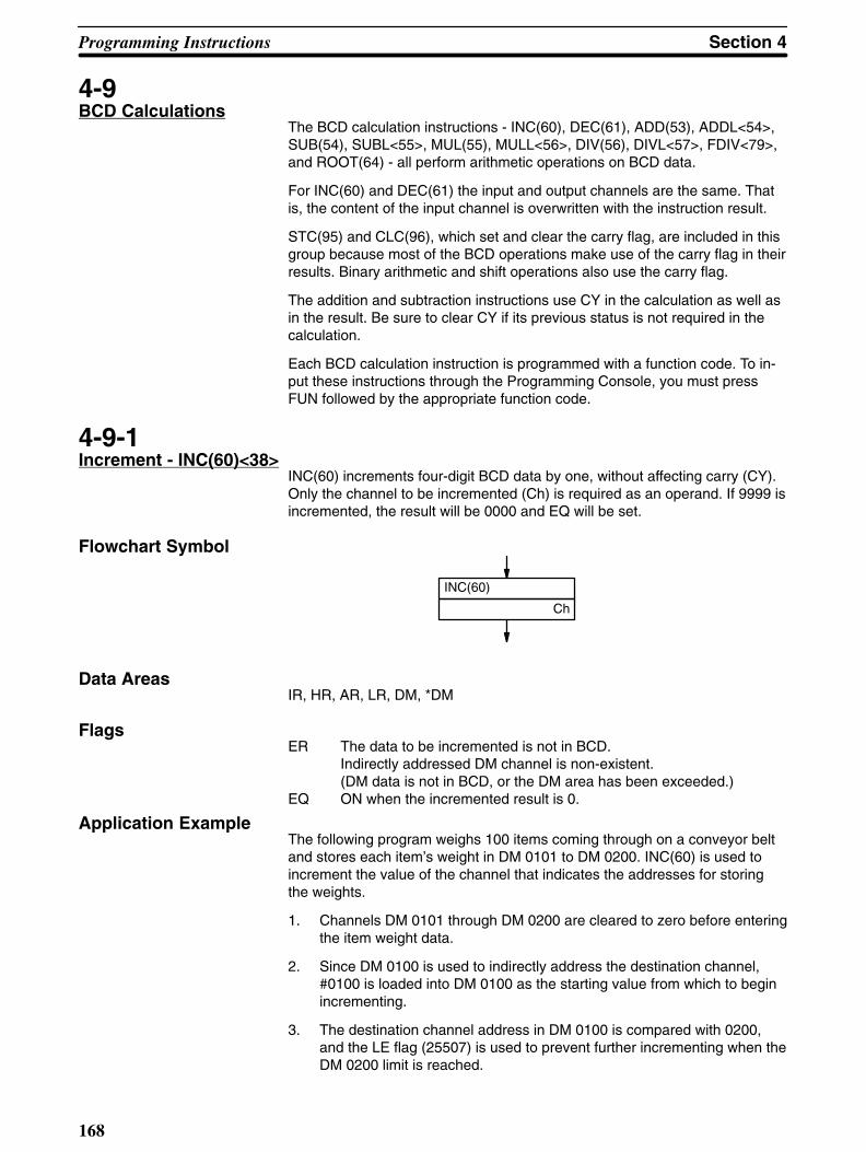
Programming Instructions Section 4
168
4-9BCD Calculations
The BCD calculation instructions - INC(60), DEC(61), ADD(53), ADDL<54>,SUB(54), SUBL<55>, MUL(55), MULL<56>, DIV(56), DIVL<57>, FDIV<79>,and ROOT(64) - all perform arithmetic operations on BCD data.
For INC(60) and DEC(61) the input and output channels are the same. Thatis, the content of the input channel is overwritten with the instruction result.
STC(95) and CLC(96), which set and clear the carry flag, are included in thisgroup because most of the BCD operations make use of the carry flag in theirresults. Binary arithmetic and shift operations also use the carry flag.
The addition and subtraction instructions use CY in the calculation as well asin the result. Be sure to clear CY if its previous status is not required in thecalculation.
Each BCD calculation instruction is programmed with a function code. To in-put these instructions through the Programming Console, you must pressFUN followed by the appropriate function code.
4-9-1Increment - INC(60)<38>
INC(60) increments four-digit BCD data by one, without affecting carry (CY).Only the channel to be incremented (Ch) is required as an operand. If 9999 isincremented, the result will be 0000 and EQ will be set.
Flowchart Symbol
INC(60)
Ch
Data AreasIR, HR, AR, LR, DM, *DM
Flags ER The data to be incremented is not in BCD.
Indirectly addressed DM channel is non-existent.(DM data is not in BCD, or the DM area has been exceeded.)
EQ ON when the incremented result is 0.
Application ExampleThe following program weighs 100 items coming through on a conveyor beltand stores each item’s weight in DM 0101 to DM 0200. INC(60) is used toincrement the value of the channel that indicates the addresses for storingthe weights.
1. Channels DM 0101 through DM 0200 are cleared to zero before enteringthe item weight data.
2. Since DM 0100 is used to indirectly address the destination channel,#0100 is loaded into DM 0100 as the starting value from which to beginincrementing.
3. The destination channel address in DM 0100 is compared with 0200,and the LE flag (25507) is used to prevent further incrementing when theDM 0200 limit is reached.

Section 4Programming Instructions
169
4. When an item arrives at the position of the scale, the photoswitch PHturns ON and increments the content of DM 0100.
5. Every time input 00001 turns ON, it outputs a weight from input channel010 to the DM channel indirectly addressed through DM 0100.
AND 00000
WAIT
Detector input: 00001
Weight input: 010
Yes
No
Jump taken after 100items completed.
MOV(50)
010
*DM 0100
JMP LBL 10
CNR
DM 0101
DM 0200
MOV(50)
#0100
DM 0100
LBL 0010
CMP(52)
DM 0100
#0200
AND 25506
CJP LBL 20
DIFU(40) 0
00001
WAIT
INC(60)
DM 0100
LBL 0020

Programming Instructions Section 4
170
4-9-2Decrement -DEC(61)<39>
DEC(61) decrements four-digit BCD data by 1, without affecting carry (CY).DEC(61) works the same way as INC(60) except that it decrements the valueinstead of incrementing it. Only the channel to be decremented (Ch) is re-quired as an operand. If 0000 is decremented, the result will be 9999.
Flowchart Symbol
DEC(61)
Ch
Data AreasIR, HR, AR, LR, DM, *DM
Flags ER The data to be decremented is not in BCD.
Indirectly addressed DM channel is non-existent.(DM data is not in BCD, or the DM area has been exceeded.)
EQ ON when the decremented result is 0.
4-9-3Set Carry - STC(95)<40>and Clear Carry -CLC(96)<41>
STC(95) sets the carry flag, CY (i.e.,turns CY ON).
CLC(96) clears the carry flag, CY (i.e, turns CY OFF).
Flowchart Symbols
CLC(96)STC(95)

!
Section 4Programming Instructions
171
The carry flag is affected by the following instructions:
Instruction Function codes Meaning of Carry Flag
1 0
ADD (53)<30> There was an overflow No overflow occurred.
ADDL <54> in the result of an
ADB <50> addition operation.
SUB (54)<31>
SUBL <55> Subtraction result Subtraction result
SBB <51> is negative is positive.
ASL (63)<25> Before shifting, bit 15 Before shifting,
ROL (70)<27> was ON. bit 15 was OFF.
ASR (62)<26> Before shifting, bit 00 Before shifting,
ROR (69)<28> was ON. bit 00 was OFF.
SFTR <84> If right-shifting, bit 00 If right-shifting, bit 00
was ON; was OFF.
If left-shifting, bit 15 If left-shifting, bit 15
was ON; was OFF.
STC (95)<40> STC was executed. ----
CLC (96)<41> ----- CLC was executed.
Caution You should execute CLC(96) before any addition, subtraction, or shift operationto ensure a correct result.
4-9-4BCD Add - ADD(53)<30>
ADD(53) adds two four-digit BCD values and the content of CY, and outputsthe result to the specified result channel. CY will be set if the result is greaterthan 9999.
Three operands are required: the augend (Au), the addend (Ad), and the re-sult channel (R).
Flowchart Symbol
ADD(53)
Au
Ad
R
Data AreasAu and Ad
IR, SR, HR, AR, LR, TC, DM, *DM, #
R
IR, HR, AR, LR, DM, *DM

Programming Instructions Section 4
172
Flags ER One or both of the channels to be added are not in BCD.
Indirectly addressed DM channel is non-existent.(DM data is not in BCD, or the DM area has been exceeded.)
CY Indicates a carry in the result.EQ ON when the resulting sum is 0.
Application ExampleThe following example adds two four-digit values and then adds two zerostogether and places the result in the channel following the first result channel.Adding zeros places the value of the carry flag into the next channel so thatany carry to the fifth digit is preserved. This same type of programming is alsouseful when adding eight-digit values to ensure that a ninth digit is not lost.
ADD(53)
#0000
#0000
DM 0101
CLC(96)
ADD(53)
LR 25
#6103
DM 0100
LR25CH
#6103
DM0101 DM0100
5 8 1 1
6 1 0 3
0 0 0 1 1 9 1 4
CY (25504) cleared to 0 with CLC(96)
Places CYin Dm 0101
4-9-5Double BCD Add -ADDL<54>
ADDL<54> totals two eight-digit values (2 channels each) and the content ofCY, and outputs the result to the specified channels. CY will be set if the re-sult is greater than 9999 9999.
Three operands are required: the first of the two augend channels (Au), thefirst of the two addend channels (Ad), and the first of the two result channels.
Flowchart Symbol
ADDL(54)
Au
Ad
R
Data AreasAu and Ad
IR, SR, HR, AR, LR, TC, DM, *DM
R
IR, HR, AR, LR, DM, *DM
Flags ER One or more of the channel contents to be added is
not in BCD.

Section 4Programming Instructions
173
Indirectly addressed DM channel is non-existent.(DM data is not in BCD, or the DM area has been exceeded.)
CY Indicates a carry in the result.EQ ON when the result is 0.
Application ExampleThe following program adds two twelve-digit values, each held in two consec-utive channels, and stores the result in four consecutive channels. The au-gend, addend, and result are 1,209,995,855, 999,090,647,200, and1,000,300,643,055, respectively. Note that CY is cleared initially because it isincluded in the first addition.
The first addition adds the rightmost eight digits of both values. The secondaddition adds the leftmost four digits of both values (because CY is set by thefirst addition, the carry from the 8th digit is included). The last addition is per-formed to place the carry from the second addition into the leftmost resultchannel.
ADD(53)
#0000
#0000
HR 13
Second addition
LR20
5 8 5 5
7 2 0 0
0 0 6 4 3 0 5 5
LR21
0 9 9 9
9 0 6 4
DM0011 DM0010
HR11 HR10
First additionCY (25504) cleared
1
1
LR22
0 0 1 2
9 9 9 0
0 0 0 3
DM0012
HR12
CY (25504) setby first addition
CLC(96)
ADDL(54)
LR 20
DM 0010
HR 10
ADD(53)
LR 22
DM 0012
HR 12
Places CYin HR13
4-9-6BCD Subtract -SUB(54)<31>
SUB(54) subtracts both a four-digit BCD subtrahend (Su) and the content ofCY from a four-digit BCD minuend (Mi) and outputs the result to the specifiedresult channel (R).
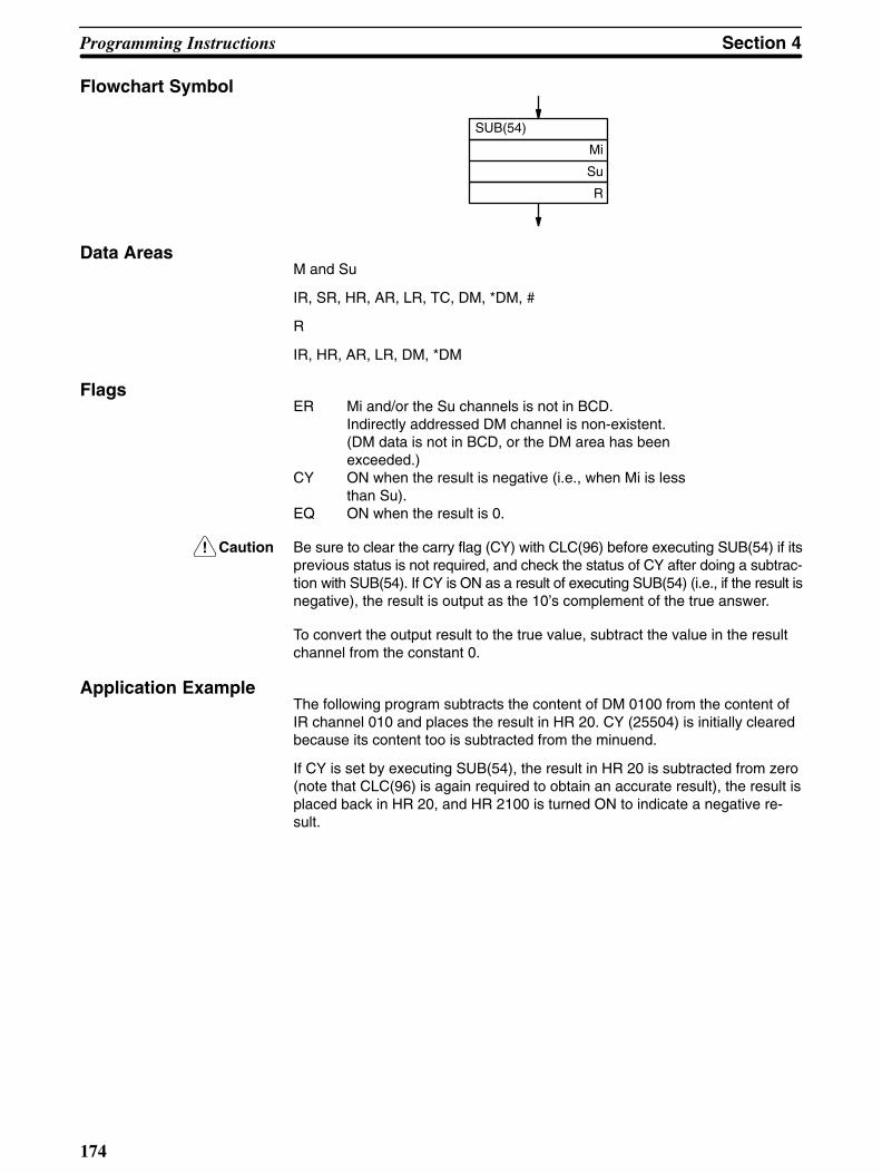
!
Programming Instructions Section 4
174
Flowchart Symbol
SUB(54)
Mi
Su
R
Data AreasM and Su
IR, SR, HR, AR, LR, TC, DM, *DM, #
R
IR, HR, AR, LR, DM, *DM
FlagsER Mi and/or the Su channels is not in BCD.
Indirectly addressed DM channel is non-existent.(DM data is not in BCD, or the DM area has been exceeded.)
CY ON when the result is negative (i.e., when Mi is less than Su).
EQ ON when the result is 0.
Caution Be sure to clear the carry flag (CY) with CLC(96) before executing SUB(54) if itsprevious status is not required, and check the status of CY after doing a subtrac-tion with SUB(54). If CY is ON as a result of executing SUB(54) (i.e., if the result isnegative), the result is output as the 10’s complement of the true answer.
To convert the output result to the true value, subtract the value in the resultchannel from the constant 0.
Application ExampleThe following program subtracts the content of DM 0100 from the content ofIR channel 010 and places the result in HR 20. CY (25504) is initially clearedbecause its content too is subtracted from the minuend.
If CY is set by executing SUB(54), the result in HR 20 is subtracted from zero(note that CLC(96) is again required to obtain an accurate result), the result isplaced back in HR 20, and HR 2100 is turned ON to indicate a negative re-sult.

Section 4Programming Instructions
175
If CY is not set by executing SUB(54), the result is positive, and SKIP(46)NOT 3 skips the steps required to convert negative results.
CLC(96)
SUB(54)
#0000
HR 20
HR 20
Yes
No
OUT NOT HR 2100
CLC(96)
SUB(54)
010
DM 0100
HR 20
LD 25504
SKIP NOT 3
OUT HR 2100
4-9-7Double BCD Subtract -SUBL<55>
SUBL<55> subtracts both an eight-digit BCD subtrahend and the content ofCY from an eight-digit BCD minuend and outputs the result to the specifiedresult channels.
Three operands are required: the first subtrahend channel (Su), the first min-uend channel (Mi), and the first result channel (R).
Flowchart Symbol
SUBL(55)
Mi
Su
R
Data AreasMi and Su
IR, SR, HR, AR, LR, TC, DM, *DM,
R
IR, HR, AR, LR, DM, *DM

!
Programming Instructions Section 4
176
Flags ER The content of the Mi, Mi+1, Su, or Su+1 channel is
not in BCD.Indirectly addressed DM channel is non-existent.(DM data is not in BCD, or the DM area has been exceeded.)
CY ON when the resulting content of R and R+1 is negative.(i.e., when M is less than Su).
EQ ON when the result is 0.
Caution Be sure to clear the carry flag (CY) with CLC(96) before executing SUBL<55> ifits previous status is not required, and check the status of CY after doing a sub-traction with SUBL<55>. If CY is ON as a result of executing SUBL<55> (i.e., ifthe result is negative), the result is output as the 10’s complement of the true an-swer.
To convert the output result to the true value, subtract the value in the resultchannel from zero. Because inputting an eight-digit constant is not possible,use CNR or BSET(73) to clear two channels to zero, and then subtract theresult from these two channels. The use of CY to check for a negative resultis the same as for SUB (see previous subsection).
4-9-8BCD Multiply -MUL(55)<32>
MUL(55) multiplies a four-digit BCD multiplicand (Md) and a four-digit BCDmultiplier (Mr) and outputs the result to the specified result channels. Twochannels are required to output the result. The first result channel (R) is inputas the third operand.
Flowchart Symbol
MUL(55)
Md
Mr
R
Data AreasMd and Mr
IR, SR, HR, AR, LR, TC, DM, *DM, #
R
IR, HR, AR, LR, DM, *DM
Flags ER The content of the Md and/or the Mr channel is not in BCD.
Indirectly addressed DM channel is non-existent.(DM data is not in BCD, or the DM area has been exceeded.)
EQ ON when the result is 0.

Section 4Programming Instructions
177
Application ExampleIn the following example, the BCD data in IR channel 067 is multiplied by theBCD data in HR 05, and the eight-digit result is output to HR 07 and HR 08.
MUL(55)
067
HR 05
HR 07
4-9-9Double BCD Multiply -MULL<56>
MULL<56> multiplies an eight-digit BCD multiplicand and an eight-digit BCDmultiplier and outputs the result to the specified result channels. Two chan-nels each are required for the multiplicand and the multiplier; four channelsare required for the result.
Three operands are required: the first multiplicand channel (Md), the first mul-tiplier channel (Mr), and the first result channel (R).
The use of MULL<56> is the same as that of MUL(55), except that longerunits of data are manipulated.
Flowchart Symbol
MULL(56)
Md
Mr
R
Data AreasMd and Mr
IR, SR, HR, AR, LR, TC, DM, *DM, #
R
IR, HR, AR, LR, DM, *DM
FlagsER Content of Md, Md+1, M, or M + 1 channels is not in
BCD.Indirectly addressed DM channel is non-existent.(DM data is not in BCD, or the DM area has been exceeded.)
EQ ON when the result is 0.
4-9-10BCD Divide - DIV(56)<33>
DIV(56) divides a four-digit BCD dividend (Dd) by a four-digit BCD divisor (Dr)and outputs the result to the specified result channels. Two channels are re-quired for the output result. The first result channel (R) is input as the thirdoperand and will receive the quotient. The second result channel will receivethe remainder.

Programming Instructions Section 4
178
Flowchart Symbol
DIV(56)
Dd
Dr
R
Data AreasDd and Dr
IR, SR, HR, AR, LR, TC, DM, *DM, #
R
IR, HR, AR, LR, DM, *DM
Flags ER The content of the Dd and/or the Dr channel is not in BCD.
Dr contains zero.Indirectly addressed DM channel is non-existent.(DM data is not in BCD, or the DM area has been exceeded.)
EQ ON when the result is 0.
4-9-11Double BCD Divide -DIVL<57>
DIVL<57> divides an eight-digit BCD dividend by an eight-digit BCD divisorand outputs the result to the specified result channels. Two channels eachare required for the dividend and the divisor; four channels are required forthe result.
Three operands are required: the first dividend channel (Dd), the first divisorchannel (Dr), and the first result channel (R). The quotient is placed in thefirst two result channels, the remainder is placed in the third and fourth.
The use of DIVL<57> is the same as that of DIV(56), except that longer unitsof data are manipulated.
Flowchart Symbol
DIVL(57)
Dd
Dr
R
Data AreasDd and Dr
IR, SR, HR, AR, LR, TC, DM, *DM
R
IR, HR, AR, LR, DM, *DM

Section 4Programming Instructions
179
Flags ER Content of Dd, Dd +1, Dr, or Dr + 1 channels is not in BCD.
Dr and Dr+1 contain zero.Indirectly addressed DM channel is non-existent.(DM data is not in BCD, or the DM area has been exceeded.)
EQ ON when the value of the result is 0.
Application ExampleThe following example divides the content of IR channels 070 and 071 by thecontent of LR 00 and LR 01. The quotient is placed in DM 1234 and DM1235; the remainder, in DM 1236 and DM 1237.
Remainder
2 3 0 0
0 0 3 5
0 2 8 1 5 7 8 0
9 8 5 5
0 0 0 0
0 0 0 0 0 0 0 0
Dd+1 : 071 Dd+1 : 070
Dr+1 : LR01 Dr : LR00
R+1 : DM1235 R : DM1234
R+3 : DM1237 R+2 : DM1236
Quotient
DIV(57)
070
LR 00
DM 1234
4-9-12Floating Point Divide -FDIV<79>
FDIV<79> divides a floating point value by another and outputs a floatingpoint result. The dividend, divisor, and resulting quotient each require twochannels (8 digits). The rightmost seven digits of each set of channels areused for the mantissa and the leftmost digit is used for the exponent. The val-id range for both the input and result is thus 0.0000001 X 10⁻⁷ through0.9999999 X 107. The resulting quotient is truncated to 7 digits.
Three operands are required: the beginning (rightmost) dividend channel(Dd), the beginning divisor channel (Dr), and the beginning result channel(R).
Flowchart Symbol
FDIV(79)
Dd
Dr
R
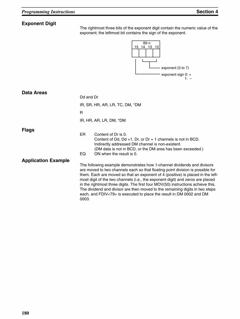
Programming Instructions Section 4
180
Exponent DigitThe rightmost three bits of the exponent digit contain the numeric value of theexponent; the leftmost bit contains the sign of the exponent.
Bit n15 14 13 12
exponent (0 to 7)
exponent sign 0: + 1: –
Data AreasDd and Dr
IR, SR, HR, AR, LR, TC, DM, *DM
R
IR, HR, AR, LR, DM, *DM
Flags ER Content of Dr is 0.
Content of Dd, Dd +1, Dr, or Dr + 1 channels is not in BCD.Indirectly addressed DM channel is non-existent.(DM data is not in BCD, or the DM area has been exceeded.)
EQ ON when the result is 0.
Application ExampleThe following example demonstrates how 1-channel dividends and divisorsare moved to two channels each so that floating point division is possible forthem. Each are moved so that an exponent of 4 (positive) is placed in the left-most digit of the two channels (i.e., the exponent digit) and zeros are placedin the rightmost three digits. The first four MOV(50) instructions achieve this.The dividend and divisor are then moved to the remaining digits in two stepseach, and FDIV<79> is executed to place the result in DM 0002 and DM0003.

Section 4Programming Instructions
181
FDIV(79)
HR 00
HR 02
DM 0002
JMP LBL 0100
FDIV<79> Execution
LBL 0100
DIFU(40) 10
00000
WAIT
MOV(50)
#0000
HR 00
MOV(50)
#0000
HR 02
MOV(50)
#4000
HR 01
MOV(50)
#4000
HR 03
MOVD(83)
DM 0000
#0021
HR 01
MOVD(83)
DM 0000
# 0300
HR 00
MOVD(83)
DM 0001
# 0021
HR 03
MOVD(83)
DM 0001
# 0300
HR 02
HR00
2 0 0 0
9 0 0 0
2 4 3 6 9 6 2 0
HR01
4 3 4 5
4 0 0 7
HR03 HR02
DM0003 DM0002
HR01
4 3 4 5
3 4 5 2
2 0 0 0
DM0000
HR00 HR03
4 0 0 7
0 0 7 9
9 0 0 0
DM0001
HR02
Dividend Divisor
#4000 initially transferred. #0000 initially transferred.
Preparations
0.3452000×10⁴
0.0079000×10⁴
0.4369620×10²
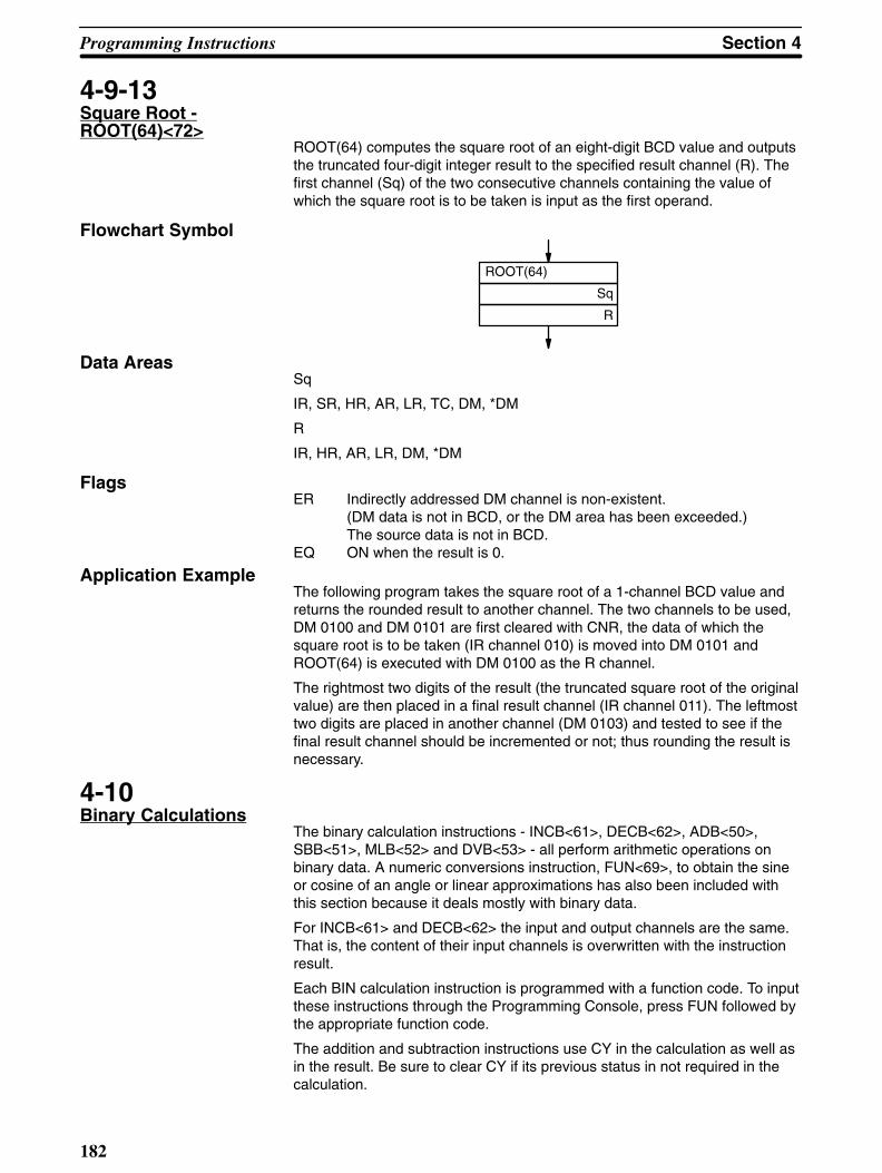
Programming Instructions Section 4
182
4-9-13Square Root -ROOT(64)<72>
ROOT(64) computes the square root of an eight-digit BCD value and outputsthe truncated four-digit integer result to the specified result channel (R). Thefirst channel (Sq) of the two consecutive channels containing the value ofwhich the square root is to be taken is input as the first operand.
Flowchart Symbol
ROOT(64)
Sq
R
Data AreasSq
IR, SR, HR, AR, LR, TC, DM, *DM
R
IR, HR, AR, LR, DM, *DM
Flags ER Indirectly addressed DM channel is non-existent.
(DM data is not in BCD, or the DM area has been exceeded.)The source data is not in BCD.
EQ ON when the result is 0.
Application ExampleThe following program takes the square root of a 1-channel BCD value andreturns the rounded result to another channel. The two channels to be used,DM 0100 and DM 0101 are first cleared with CNR, the data of which thesquare root is to be taken (IR channel 010) is moved into DM 0101 andROOT(64) is executed with DM 0100 as the R channel.
The rightmost two digits of the result (the truncated square root of the originalvalue) are then placed in a final result channel (IR channel 011). The leftmosttwo digits are placed in another channel (DM 0103) and tested to see if thefinal result channel should be incremented or not; thus rounding the result isnecessary.
4-10Binary Calculations
The binary calculation instructions - INCB<61>, DECB<62>, ADB<50>,SBB<51>, MLB<52> and DVB<53> - all perform arithmetic operations onbinary data. A numeric conversions instruction, FUN<69>, to obtain the sineor cosine of an angle or linear approximations has also been included withthis section because it deals mostly with binary data.
For INCB<61> and DECB<62> the input and output channels are the same.That is, the content of their input channels is overwritten with the instructionresult.
Each BIN calculation instruction is programmed with a function code. To inputthese instructions through the Programming Console, press FUN followed bythe appropriate function code.
The addition and subtraction instructions use CY in the calculation as well asin the result. Be sure to clear CY if its previous status in not required in thecalculation.

Section 4Programming Instructions
183
Data displays on the Programming Console and explanations in followingsubsections all use hexadecimal representation and refer to the number ofhexadecimal digits. Names of instructions, however, have been kept in binaryterms because actual computer operations are in binary. The arithmetic resultwill always be the same, regardless of whether hexadecimal or the equivalentbinary representation of numbers are manipulated. Binary and hexadecimalrepresentations are easily converted back and forth because four binary dig-its always represent one hexadecimal digit, e.g., binary 1111 represents hexa-decimal F; binary 0010, hexadecimal 2; and binary 1111 0010, hexadecimalF2.
Programming applications of binary instructions are similar to those of BCDinstructions. Basically only the type of data being dealt with is different. Referto Application Examples under corresponding instructions in 4-8 BCD Calcu-lations as necessary.
4-10-1Binary Increment -INCB<61>
INCB<61> increments 4 digits of hexadecimal data by one, without affectingcarry (CY). Only the channel to be incremented (Ch) is required as an oper-and. If FFFF is incremented, the result will be 0000 and EQ will be set.
Flowchart Symbol
INCB(61)
Ch
Data AreasIR, HR, AR, LR, DM, *DM
Flags ER Indirectly addressed DM channel is non-existent.
(DM data is not in BCD, or the DM area has been exceeded.)EQ ON when the incremented result is 0.
4-10-2Binary Decrement -DECB<62>
DECB<62> decrements four digits of hexadecimal data by 1, without affectingcarry. Only the channel to be decremented (Ch) is required as an operand. If0000 is decremented, the result will be FFFF.
Flowchart Symbol
DECB(62)
Ch
Data AreasIR, HR, AR, LR, DM, *DM
Flags ER Indirectly addressed DM channel is non-existent.
(DM data is not in BCD, or the DM area has been exceeded.)EQ ON when the decremented result is 0.

Programming Instructions Section 4
184
4-10-3Binary Addition -ADB<50>
ADB<50> adds a four-digit augend (Au), a four-digit addend (Ad), and thecontent of CY and outputs the result to the specified result channel. If the re-sulting sum is greater than FFFF, the carry flag (CY) will be set.
Flowchart Symbol
ADB(50)
Au
Ad
R
Data AreasAu and Ad
IR, SR, HR, AR, LR, TC, DM, *DM, #
R
IR, HR, AR, LR, DM, *DM
Flags ER Indirectly addressed DM channel is non-existent.
(DM data is not in BCD, or the DM area has been exceeded.)CY ON when the result is greater than FFFF.EQ ON when the result is 0.
4-10-4Binary Subtraction -SBB<51>
SBB<51> subtracts a four-digit hexadecimal subtrahend (Su) and the contentof carry from a four-digit hexadecimal minuend (Mi) and outputs the result tothe specified result channel (R).
If the difference is a negative value, SBB<51> sets CY and outputs the 2’scomplement of the difference to the result channel. CY must therefore betested after using SBB<51> and the result must be subtracted from zero toobtain the true negative difference if CY is set.
Flowchart Symbol
SBB(51)
Mi
Su
R
Data AreasMi and Su
IR, SR, HR, AR, LR, TC, DM, *DM, #
R
IR, HR, AR, LR, DM, *DM

Section 4Programming Instructions
185
FlagsER Indirectly addressed DM channel is non-existent.
(DM data is not in BCD, or the DM area has been exceeded.)CY ON when the result less than 0.EQ ON when the result is 0.
4-10-5Binary Multiplication -MLB<52>
MLB<52> multiplies a four-digit hexadecimal multiplicand (Md) by a four-digitmultiplier (Mr) and outputs the eight-digit hexadecimal result to the specifiedresult channels. The first result channel (R) is input as the third operand.
Flowchart Symbol
MLB(52)
Md
Mr
R
Data AreasMd and Mr
IR, SR, HR, AR, LR, TC, DM, *DM, #
R
IR, HR, AR, LR, DM, *DM
Flags ER Indirectly addressed DM channel is non-existent.
(DM data is not in BCD, or the DM area has been exceeded.)EQ ON when the result is 0.
4-10-6Binary Division -DVB<53>
DVB<53> divides a four-digit hexadecimal dividend (Dd) by a four-digit divisor(Dr) and outputs the quotient to the specified result channel (R). The remain-der is output to the next channel after R.
Flowchart Symbol
DVB(53)
Dd
Dr
R
Data AreasDd and Dr
IR, SR, HR, AR, LR, TC, DM, *DM, #
R
IR, HR, AR, LR, DM, *DM

Programming Instructions Section 4
186
Flags ER Dr is zero.
Indirectly addressed DM channel is non-existent.(DM data is not in BCD, or the DM area has been exceeded.)
EQ ON when the result is 0.
4-10-7Numeric Conversions-FUN<69>
This instruction is used to compute the sine and cosine of angles between 0°and 90°, as well as to compute linear approximations from tables definingpoints forming connected line segments.
Three operands are required: the control data (C), the source channel (S),and the result channel (R). The control data defines which operation is to beused, i.e., #0000 is input as the control data for sine calculation; #0001 is in-put for cosine calculation; and a channel is designated for linear approxima-tion.
If a channel is designated for linear approximation, then the designated chan-nel defines parameters for the approximation and the line table defining thepoints used for approximation follows in channels immediately after C (seebelow for details). The line table must all be in the same data area and it can-not be in both the normal DM area and the expanded portion of DM area (ifexpanded DM area is used), although it can be completely in either normalDM area or completely in the expanded portion (i.e., beyond DM 4096).
Flowchart Symbol
FUN(69)
C
S
R
Data AreasC
IR, SR, HR, AR, LR, DM, *DM, # (0000 or 0001 only)
S
IR, SR, HR, AR, LR, DM, *DM
R
IR, HR, AR, LR, DM, *DM
Flags ER Indirectly addressed DM channel is non-existent.
(DM data is not in BCD, or the DM area has been exceeded.)An angle greater than 90° has been designated for sine or cosineconversion.Table data for linear approximation is not in proper format.
EQ ON when result is 0.
Sine and CosineIf #0000 is input for the control data, the content of the source channel is as-sumed to be an angle with one decimal place (e.g., 0300 is 30.0°) and thesine of the angle will placed in the result channel to the forth place past thedecimal point (e.g., 5000 is 0.5). The fifth place past the decimal is truncated.

Section 4Programming Instructions
187
If #0001 is input for the control data, the cosine of the content of the sourcechannel will be placed in the result channel in the same fashion as the sine isfor #0000.
Linear ApproximationIf the control data is a channel designation, the content of the designatedchannel will set parameters for linear approximation based on connected linesegments formed from the table of points found in the channels following thechannel designated as control data. The content of the source channel will beassumed to be an X coordinate and the Y coordinate necessary to produce apoint on one of the line segments in the line table will be output to the resultchannel.
Parameters given in the channel designated for control data are as follows:Bit 1 is set to 0 if source data is in BCD, 1 if it is binary; bit 2 is set to 0 if theresult is to be in BCD, 1 if it is to be in binary; and bits 0 through 7 are set toone less than the number of points defined in the line table. Bits 8 through 13of the designated channel are not used and should be set to zero.
The points in the line table, Xn and Yn, must be input in binary so that Yn is afunction of Xn and so that Xn is less than Xn+1 (i.e., X coordinates must be inascending order). These points will form connected lines segments and areheld in the data area following channel C shown below. Note that the last Xcoordinate, Xm is listed both first and next to last, and that X0, which is as-sumed to be zero, is not listed in the table.
Y0
Y1
Y2
X1
X2
Yn
Xn
Ym
Xm
Xm
Y
X
Y2
Y0
Y1
Y3
Y4
X0 X1 X2 X3 X4 Xm
C+1
C+2
C+3C+4
C+5
C+6
C+ (2m+1)
C+ (2m+2)
The Y coordinate for a given X coordinate will be computed from the two Xcoordinates in the table between which the given X coordinate lies. If the giv-en X coordinate falls between Xn and Xn+1, the equation for the resulting Ycoordinate is as follows:
Y = Yn + (X – Xn) x (Yn+1 – Yn)/(Xn+1 – Xn)
Linear ApproximationApplication Example
The following instruction block and line table show how linear approximationworks. Here the corresponding Y coordinate (R) for an X coordinate (S) of0014 (content of IR channel 010) is computed using a table containing 12

Programming Instructions Section 4
188
points. The line segments are also plotted below for convenience. Actual cal-culations are as follows:
Y (R) = F00 + (14 – 5) x (402 – F00)/(1A–5)
= F00 – F x 86
= 726
FUN(69)
DM0000
010
011
1 1 0 0 1 0 1DM0000
DM0001
DM0002DM0003
DM0004
DM0005
DM0006
DM0025DM0026
C 0 0 B
0 5 F 0
0 0 0 0
0 0 0 5
0 F 0 0
0 0 1 A
0 4 0 2
0 5 F 0
1 F 2 0
Y0
X12
Y1
X1
Y2
X2
X12
Y12
1
15 14 3 2 1 0
Channel designation for linear approximation
Source channel
Result channel
S and R both binary 12 (# of points) – 1
1F20
0F00
07260402
0005 0014 001A 05F0
Y
X
4-11Logic Instructions
The logic instructions - COM(71), ANDW(65), ORW(66), XORW(67), andXNRW(68) - perform logic operations on channel data.
Each logic instruction is programmed with a function code. To input these in-structions through the Programming Console, press FUN followed by the ap-propriate function code.
4-11-1Complement -COM(71)<29>
COM(71) inverts the bit status of one channel of data. That is, COM(71)clears all ON bits and sets all OFF bits in the channel specified (Ch).
To obtain the inverted status of a channel when working in hexadecimal, sub-tract each hexadecimal digit from 15 to get the hexadecimal digit correspond-ing to the inverted bits.
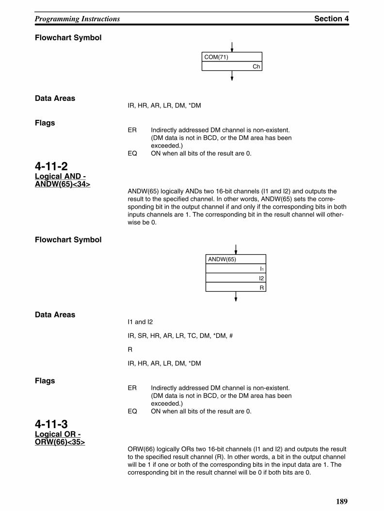
Section 4Programming Instructions
189
Flowchart Symbol
COM(71)
Ch
Data Areas IR, HR, AR, LR, DM, *DM
Flags ER Indirectly addressed DM channel is non-existent.
(DM data is not in BCD, or the DM area has been exceeded.)
EQ ON when all bits of the result are 0.
4-11-2Logical AND -ANDW(65)<34>
ANDW(65) logically ANDs two 16-bit channels (I1 and I2) and outputs theresult to the specified channel. In other words, ANDW(65) sets the corre-sponding bit in the output channel if and only if the corresponding bits in bothinputs channels are 1. The corresponding bit in the result channel will other-wise be 0.
Flowchart Symbol
ANDW(65)
I1
I2
R
Data AreasI1 and I2
IR, SR, HR, AR, LR, TC, DM, *DM, #
R
IR, HR, AR, LR, DM, *DM
Flags ER Indirectly addressed DM channel is non-existent.
(DM data is not in BCD, or the DM area has been exceeded.)
EQ ON when all bits of the result are 0.
4-11-3Logical OR -ORW(66)<35>
ORW(66) logically ORs two 16-bit channels (I1 and I2) and outputs the resultto the specified result channel (R). In other words, a bit in the output channelwill be 1 if one or both of the corresponding bits in the input data are 1. Thecorresponding bit in the result channel will be 0 if both bits are 0.

Programming Instructions Section 4
190
Flowchart Symbol
ORW(66)
I1
I2
R
Data AreasI1 and I2
IR, SR, HR, AR, LR, TC, DM, *DM, #
R
IR, HR, AR, LR, DM, *DM
Flags ER Indirectly addressed DM channel is non-existent.
(DM data is not in BCD, or the DM area has been exceeded.)
EQ ON when all bits of the result are 0.
4-11-4Exclusive OR -XORW(67)<36>
XORW(67) exclusively ORs two 16-bit data channels (I1 and I2) and outputsthe result to the specified result channel (R). In other words, a bit in the out-put channel will be set to 1 only when the corresponding bits in the inputchannels differ. If corresponding bits are both 1 or both 0, the resulting bit willbe 0.
Flowchart Symbol
XORW(67)
I1
I2
R
Data AreasI1 and I2
IR, SR, HR, AR, LR, TC, DM, *DM, #
R
IR, HR, AR, LR, DM, *DM
Flags ER Indirectly addressed DM channel is non-existent.
(DM data is not in BCD, or the DM area has been exceeded.)EQ ON when all bits of the result are 0.
4-11-5Exclusive NOR -XNRW(68)<37>
XNRW(68) exclusively NORs two 16-bit channels (I1 and I2) and outputs theresult to the specified result channel (R). In other words, a bit in the output

Section 4Programming Instructions
191
channel will be 1 only when the corresponding bits in the input channels arethe same. If the status of corresponding bits differ, the result channel will beset to 0.
Flowchart Symbol
XNRW(68)
I1
I2
R
Data AreasI1 and I2
IR, SR, HR, AR, LR, TC, DM, *DM, #
R
IR, HR, AR, LR, DM, *DM
Flags ER Indirectly addressed DM channel is non-existent.
(DM data is not in BCD, or the DM area has been exceeded.)EQ ON when all bits of the result are 0.
4-12Group Programs
Programming groups of instructions allows various processes to proceed to-gether. Although only one group program or the main program is executing atany one time, execution moves between the main program and the variousgroup programs whenever certain conditions are met, resulting in essentiallyparallel execution when considering the high execution speed.
Group programs are always programmed at addresses after the end of themain program.
4-12-1Basic Instructions -GN(10), GS(11), GE(12),GOFF(15), and GJ(17)
Group Start, GS(11), prepares group programs for execution; Group Number,GN(10), defines a group program; Group End, GE(12), defines the end of agroup program; Group Off, GOFF(15), turns a group program off or definesthe end of a group program; and Group Jump, GJ(17), moves execution tothe next group program awaiting execution. All of these instructions exceptfor GJ(27) require a group program number (N) between 000 and 127. Eachnumber must be used for one group program only, and the same numbermust be used at the beginning and end of the same group program.
All group program programs must begin with GN(11) and end with eitherGE(12) or GOFF(15).
The group program number is input as part of the instruction line, i.e., be-tween the FUN number and ENT. No operands are required for any of theseinstructions.

Programming Instructions Section 4
192
Flowchart Symbols
GOFF(15) N
GS(11) N
GJ(17)
GN(10) N
GE(12) N
Group Program Execution
Although group programs allow for parallel execution of several programs,the programs are not actually executed simultaneously, but in order accordingto the group program numbers. Execution always begins with the main pro-gram and then moves to the next group program that is awaiting execution.
All group programs are placed in an ‘off’ (ended) condition when PC power isturned on or when the PC is changed from PROGRAM to RUN or MONITORmode. To prepare a program for execution, it must be placed on standby byusing GS(11). GS(11) must again be used if a program is going to be ex-ecuted again after reaching GE(12) (or GOFF(15)) or after having beenstopped with GOFF(15).
Group program execution is actually begun when one of four conditions isencountered in the main program: GJ(17), WAIT with an OFF execution con-dition, WAIT NOT with an ON execution condition, or SBS(32) for a subrou-tine that is already under execution. If there is one or more group programsawaiting execution (i.e., GS(11) has been executed for them) when one ofthese conditions is encountered, execution moves to the lowest numberedgroup program awaiting execution.
Once a group program has begun execution, it will continue execution untilGE(12) (or GOFF(15)) has been reached or until one of the above four condi-tions is encountered. Once GE(12) or one of these conditions is encountered,execution of the next lowest number group program awaiting execution is be-gun and continues until GE(12) has been reached or until one of the four con-ditions is encountered again.
When the last group program awaiting execution has begun execution andhas reached GE(12) or has encountered one of the above conditions, themain program is returned to at the point from which program execution wasbegun. The main program will continue execution until again one of the aboveconditions for group program execution is encountered, when group programexecution will again be performed as described above. The process will con-tinue in cyclic fashion, moving from the main program to the lower numbergroup program awaiting execution, then through the group programs in orderaccording to group program number, and then back to the main programonce the highest numbered group program awaiting execution has been left.
When a group program that has not completed execution is re-entered, ex-ecution continues from the point where execution was interrupted. A group

Section 4Programming Instructions
193
program will thus be entered as many times as necessary to reach GE(12)(or GOFF(15)).
Once GE(12) has been executed for a group program, that group program isno longer on standby, and GS(11) must be re-executed for it before it will beexecuted again (i.e., before it will be placed back on standby. GS(11) mustalso be re-executed for a group program for which GOFF(15) has been ex-ecuted.
GOFF(15) and GE(12)Either GOFF(16) or GE(12) may be used at the end of a group program withthe following differences.
When GE(12) is executed for a group program, it goes off standby, but thestatus of all outputs, counters, and timers in the group program are main-tained and timers continue operation.
A designated group program also goes off standby when GOFF(15) is ex-ecuted for it; however, all IR and LR outputs bits (i.e., those used in OUT,OUT NOT, OUTC(00), and OUTC(00) NOT) and timers will be reset throughthe first SBN(31) or GN(10) for any program group number or the firstGE(12), or GOFF(15) for the designated program group number, following theGN(10) of the designated program group number. If none of these are en-countered, resetting will continue through the final address.
Jumps and Labels inGroup Programs
CJP, RPT(37), SKIP(46), and BRZ(59) may be used in a group program tobranch within the group program. All branches (i.e., destinations) for theseinstructions must lie within the same group program. You cannot branch fromone group program to another or to/from the main program. All jumps be-tween group programs and to/from the main program must be achieved asdescribed above.
Monitoring Group StatusThe four statuses of a group, awaiting execution, under execution, ended,and pause (see 4-11-2 Group Pause - GP(13) and Group Restart - GR(14)),can be monitored from the Programming Console. See 2-4-11 Group Monitor.Group program status can also be monitored through Group Execution flagsin AR channels 00 through 07. These flags are ON when a group is awaitingexecution, under execution, or pausing. See 3-5 Auxiliary Relay Area - AR.

Programming Instructions Section 4
194
Application Example:Basic Group ProgramExecution
The following program using two group programs is described below.
Emergencystop button
Yes
No
Yes
No
Start button
GE(12) 001
LBL 0000
AND 00000
SKIP NOT 2
GS(11) 000
GS(11) 001
AND 00007
SKIP NOT 2
GOFF(15) 000
GOFF(15) 001
GJ(17)
JMP LBL 000
GN(10) 000
OUT 00500
AND 00001
WAIT
OUT NOT 00500
OUT 00502
AND 00003
WAIT
OUT 00501
AND 00002
WAIT
OUT NOT 00501
OUT NOT 00502
GE(12) 000
GN(10) 001
AND 00004
WAIT
OUT 00503
AND 00005
WAIT
OUT NOT 00503
OUT 00504
AND 00006
WAIT
OUT NOT 00504
1. When the start button goes ON, group programs 0 and 1 are placed onstandby.
2. If the emergency button is OFF, GJ is executed, moving execution to thebeginning of group program 0.
3. Group program 0 is executed through AND 00001. If input 00001 is OFF,execution moves to group program 1. If input 00001 is ON, execution ofgroup program 0 continues.
4. When execution moves to group program 1, execution continuesthrough AND 00004. If input 00004 is OFF, execution moves back to themain program. If input 00004 is ON, execution of group program 1 con-tinues.
5. When the main program is returned to and loops back to the beginning,the GS(11) are ignored if the group programs are already on standby.
6. When GJ is executed again, execution returns to group program 0, re-turning to the point from which it was left (to the beginning if it was com-pleted).
7. Execution continues moving though the programs until execution isstopped.

Section 4Programming Instructions
195
8. If the emergency stop button is pressed during execution, GOFF(15)resets the group programs.
Note that if all WAITs in the group programs cause jumps out of the groupprograms, then each group program would have to be entered four times be-fore reaching GE(12).
Application Example:Sequential Execution
The following example shows the use of Group Execution flags to control thesequence of group program execution. In the following example, the mainprogram is divided into three sections linked with CJP jumps. These jumpsare taken only when the group program(s) associated with that section of themain program has completed execution.
The first section places group program 0 on standby, executes program sec-tion 1 (indicated by the dotted line), and then jumps to group 0 (we’ll assumethat nothing in program section 1 would cause a jump). When group 0 is left,execution returns to the main group (because no other group programs areawaiting execution). If group program 0 was executed through completion,AR 0000 (the Group Execution flag for group program 0) will be OFF, and thenext section of the main program will be jumped to from CJP LBL 2. If groupprogram 0 has not completed execution, label 1 will be returned to, programsection 1 will be executed again, group program 0 will be jumped to, and theprocess will be repeated until group program 0 is completed and label 2 atthe beginning of the second section of the main program is jumped to.
The second section of the main program places groups 1 and 2 on standby,then repeats program section 2 and group programs 1 and 2 until both groupprograms 1 and 2 are completed. Note that because now two group pro-grams are awaiting execution, jumps will be made from group program 1 togroup program 2 (as long as both group programs are awaiting execution)before returning to the main program. When execution of both group pro-grams 1 and 2 has completed, CJP LBL 4 moves execution to the third sec-tion of the main program.

Programming Instructions Section 4
196
The third section of the main program is link to group program 3, which is ex-ecuted alternately with program section 3 until the group program is com-pleted. When group program 3 has completed execution, the first section ofthe main program is returned to, beginning the process again.
Yes
No
Yes
No
Yes
No
GE(12) 002
LBL 0000
GS(11) 000
LBL 0001
GJ(17)
AND NOT AR 0000
CJP LBL 2
JMP LBL 1
LBL 0002
GS(11) 001
GS(11) 002
LBL 0003
GJ(17)
AND NOT AR 0001
AND NOT AR 0002
CJP LBL 4
JMP LBL 3
LBL 0004
GS(11) 003
LBL 0005
GJ(17)
AND NOT AR 0003
CJP LBL 0
JMP LBL 5
GE(12) 000
GN(10) 000 GN(10) 001
GE(12) 001
GN(10) 003
GE(12) 003
GN(10) 002

Section 4Programming Instructions
197
4-12-2Group Pause - GP(13)and Group Restart -GR(14)
Any group for which GS(11) has been executed, but for which neither GE(12)nor GOFF(15) has be executed, can be placed in a “pause” condition by ex-ecuting GP(13) for that group program number. The group program will thenremain in a pause condition until GR(14), GS(11), GE(12) or GOFF(15) isexecuted for it.
If GR(14) is executed for a paused group program, the group program will goon standby and continue execution from the point at which GP(13) was ex-ecuted the next time the group program is jumped to.
If GS(11) is executed for a paused group program, the group program will goon standby and continue execution from the beginning of that group programthe next time the group program is jumped to.
If GE(12) or GOFF(15) is executed for a paused group program, the groupprogram will be ended and GS(11) must be executed for it again to execute it.
GP(13) will be ignored if executed for a group program already in a pausecondition or for a group program that has been ended and not placed back onstandby.
If GP(13) is executed for a group program that is being executed, a jump willbe made to the next group program awaiting execution or back to the mainprogram if no group programs are awaiting execution.
The group program number (N) of the group program for which GP(13) orGR(14) is being executed is input as part of the instruction line, i.e., betweenthe function code and ENT. No operands are required. The group programnumber must be between 000 and 127, inclusive.
Flowchart Symbols
GR(14) NGP(13) N
4-12-3Group Continue - GC(16)
GC(16) is used together with the Group Continue Control bit, SR bit 25211,and the Data Retention Control bit, SR bit 25212, to continue group programexecution or interrupt routine execution when restarting after a power inter-ruption.
If SR bits 25211 and 25212 are ON, all group programs for which GC(16) isexecuted after restarting will be continued from the point of interruption thenext time they are entered (program execution following power interruptionsalways begins at the beginning of the main program (address 00000).
If GS(11) is executed for a group program before GC(16) for any group pro-gram, execution of that group program will be restarted from the beginningthe next time it is entered.
Timers and counters will retain status during power interruptions. (These canbe reset as necessary using CNR.) Timers in group programs will be re-started following power interruption only after GJ(17) has been executed.

Programming Instructions Section 4
198
The group program number, N, is input as part of the instruction line, i.e., af-ter inputting the FUN number and before pressing ENT. Group program num-bers are between 000 and 127, inclusive. Designate group program number129 to execute GC(16) for I/O interrupt routines; number 130, for the sched-uled interrupt routine.
Flowchart Symbol
GC(16) N
Application ExampleThe following program shows use of the Output OFF bit, 25215, to jump to aprogram section that determines group program execution following powerinterruption. (Bit 25215 is automatically turned ON following a power interrup-tion if the Group Continue Control bit and Data Retention Control bits, bits25211 and 25212, are both ON.)
The following program is designed to continue execution of group programs 0though 99 at the point where they were interrupted and to restart execution ofgroup program 100 from the beginning.
Note that bit 25215 is reset so that it will not necessarily be ON the next timethe program is executed.
GOFF(15) 100
OUT NOT 25215
JMP LBL2
Group program100 reset.
Yes
No Group program0 through 99continued.
OUT 25211
OUT 25212
AND 25215
CJP LBL 0
LBL 0001
GS(11) 000
GS(11) 001
GS(11) 100
LBL 0002
GJ(17)
JMP LBL1
LBL 0000
GC(16) 000
GC(16) 001

Section 4Programming Instructions
199
4-12-4AND Group - ANDG(01)and OR Group - ORG(02)
ANDG(01) and ORG(02) are used to designate group program or interruptroutine status as the execution condition for WAIT, CJP, SKIP(46), orOUTC(00).
An ‘ON’ condition is created if GS(11) has been executed for the group pro-gram, but neither GE(12) nor GOFF(15) has been. Otherwise an ‘OFF’ condi-tion is created. ANDG(01) and ORG(02) can also be used with NOT to re-verse these conditions.
ANDG(01) ANDs the execution condition with the execution condition beforeit; ORG(02) ORs it.
The group program number, N, is input as part of the instruction line, i.e., af-ter inputting the FUN number and before pressing ENT. Group program num-bers are between 000 and 127, inclusive. Designate group program number129 to execute for I/O interrupt routines; number 130, for the scheduled inter-rupt routine.
Note: If a group program number that is not used in the program is desig-nated, an OFF condition will be created.
Flowchart Symbols
ORG(02) NOT N
ANDG(01) N
ORG(02) N
ANDG(01) NOT N
4-13Subroutines andInterrupt Control
4-13-1Overview
Subroutines break large control tasks into smaller ones and enable you toreuse a given set of instructions. When the main program calls a subroutine,control is transferred to the subroutine and the subroutine instructions areexecuted. The instructions within a subroutine are written in the same way asmain program code. When all the subroutine instructions have been ex-ecuted, control returns to the main program to the point just after the subrou-tine call.
Interrupt routines are different from subroutines in that they are activated byinterrupt signals, by power interruptions, or at specific time intervals ratherthan by subroutine calls. Like subroutine calls, interrupts cause a break in theflow of the main program execution such that the flow can be resumed fromthat point at a later time. Interrupts are used to deal with special circum-stances, such as emergency situations, power interruptions, status confirma-tions, etc.

Programming Instructions Section 4
200
Multiple interrupts from different sources can occur at the same time. To ef-fectively deal with this, the PC employs a priority scheme for handling inter-rupts.
In the case of the scheduled interrupt, the time interval between interrupts isset by the user and is unrelated to the program execution time. This capabilityis useful for periodic supervisory or executive program execution.
Interrupts can be masked to prevent an interrupt routine from being executedwhere it is not needed or where interrupting the program is not desirable.
4-13-2Subroutine Definition -SBN(31)<92> andRET(33)<93>
SBN(31) and RET(33) mark the beginning and end, respectively, of a subrou-tine definition. All subroutines are defined with a subroutine number (N) thatmust be between 000 and 999. N is input as part of the SBN(31) instructionline, i.e. after the function code but before pressing ENT. The subroutinenumber is not required when inputting RET.
Flowchart Symbols
RET(33)SBN(31) N
Instructions for subroutines (i.e., instructions bounded by SBN(31) and RET)should be placed just after the main program code. When the CPU reachesthe first SBN(31) in the program, it assumes that it has reached the end of themain program area. That is, the CPU scans that portion of the program fromaddress 00000 to the first SBN(31).
A total of 1,000 subroutines may be defined (i.e., from 000 to 999).
4-13-3Subroutine Entry -SBS(32)<91>
The main program calls a subroutine by means of SBS(32).
When SBS(32) is encountered during program execution, program control istransferred to the subroutine whose number, N, is input with SBS(32). Whenthe subroutine instructions between SBN(31) and RET(33) for the designatesubroutine have been executed, control returns to the instruction following theSBS(32) that called the subroutine.
Flowchart Symbol
SBS(32) N
The number of subroutine calls (i.e., the number of times that SBS(32) can beused) that can be made is unlimited.
Subroutines can be nested (i.e., a subroutine can call another subroutine) upto as many levels as required. There is no limit.
FlagsER The specified subroutine does not exist.
A subroutine has called itself.

Section 4Programming Instructions
201
RestrictionsAny SBS(32) that calls an undefined subroutine will be processed as a NOPand program execution will continue to the next instruction.
A subroutine may not call itself. If an attempt is made to call a subroutinefrom within the same subroutine, program execution will stop.
If a jump to a subroutine that is already under execution is attempted (as canhappen with group programs), a jump will be made to the next group programawaiting execution and the attempted jump to the subroutine will be madewhen the initial execution of the subroutine has completed. If the jump to thesubroutine under execution was attempted from an interrupt routine, however,program execution will stop and remain on standby without jumping to anoth-er group program.
Subroutine execution status can be check with SBT(34) to ensure that an at-tempt in not made to jump to a subroutine under execution (see next subsec-tion).
4-13-4Subroutine Test -SBT(34)
SBT(34) is used to check the execution status of a subroutine to preventjumps to subroutines under execution. The number of the subroutine (N: 000through 999) to be tested is input as part of the instruction line, i.e., after thefunction code and before pressing ENT.
SBT(34) must be used in combination and just before WAIT, CJP, SKIP(46),or OUTC(00). The instruction following SBT(34) is executed with the execu-tion condition determined by the status of the subroutine (YES: not under ex-ecution; NO: under execution).
If SBT(34) is used before WAIT, program execution will pause until the sub-routine is not being executed and then proceed to the next instruction. If agroup program is awaiting execution, this WAIT will cause a jump to the nextgroup program.
IF SBT(34) is used before CJP or SKIP(46), the program will follow the YESand NO branches according to the execution status of the designated subrou-tine.
If SBT(34) is used before OUTC(00), the output will be turned ON if the sub-routine is not being executed.
NOT may be combined with any of these instructions to reverse the responsegiven above.
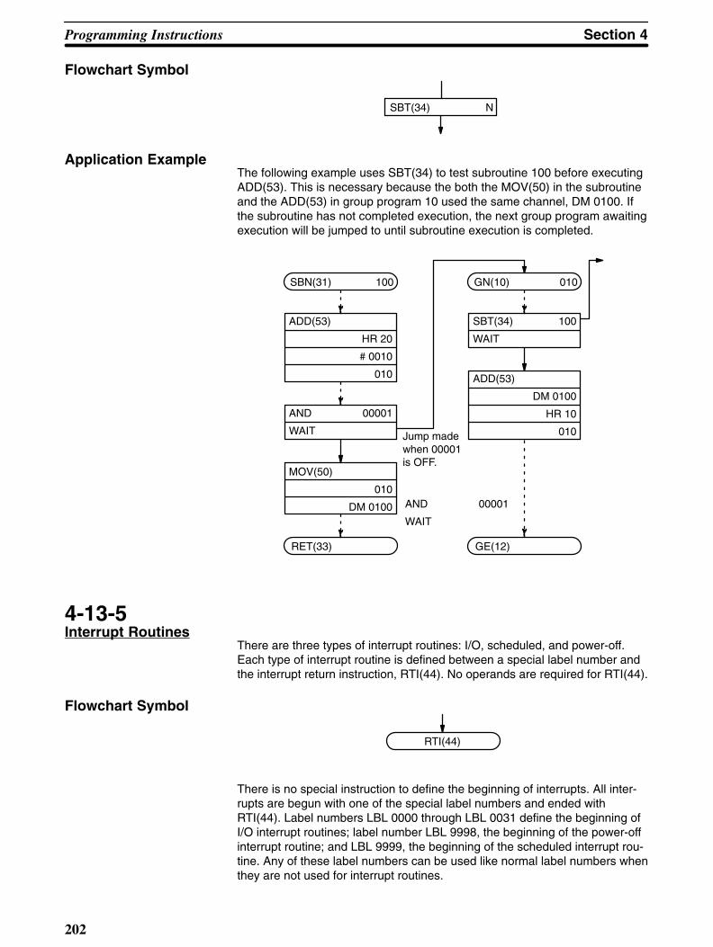
Programming Instructions Section 4
202
Flowchart Symbol
SBT(34) N
Application ExampleThe following example uses SBT(34) to test subroutine 100 before executingADD(53). This is necessary because the both the MOV(50) in the subroutineand the ADD(53) in group program 10 used the same channel, DM 0100. Ifthe subroutine has not completed execution, the next group program awaitingexecution will be jumped to until subroutine execution is completed.
ADD(53)
DM 0100
HR 10
010Jump madewhen 00001is OFF.
SBN(31) 100
ADD(53)
HR 20
# 0010
010
AND 00001
WAIT
AND 00001
WAIT
MOV(50)
010
DM 0100
RET(33)
GN(10) 010
SBT(34) 100
WAIT
GE(12)
4-13-5Interrupt Routines
There are three types of interrupt routines: I/O, scheduled, and power-off.Each type of interrupt routine is defined between a special label number andthe interrupt return instruction, RTI(44). No operands are required for RTI(44).
Flowchart Symbol
RTI(44)
There is no special instruction to define the beginning of interrupts. All inter-rupts are begun with one of the special label numbers and ended withRTI(44). Label numbers LBL 0000 through LBL 0031 define the beginning ofI/O interrupt routines; label number LBL 9998, the beginning of the power-offinterrupt routine; and LBL 9999, the beginning of the scheduled interrupt rou-tine. Any of these label numbers can be used like normal label numbers whenthey are not used for interrupt routines.

!
Section 4Programming Instructions
203
Whenever an interrupt routine is triggered, the instruction being executed atthat time is completed and a jump is made to the label number defining theinterrupt routine that has been triggered. Normal program execution is re-turned to at the point it was interrupted following completion of the interruptroutine (i.e., when RTI(44) is executed), except for power-off interrupts, whichend program execution after completion of the routine.
I/O interrupt routines are not executed when masked, and all I/O interruptsare masked immediately after PC power is turned ON (see next subsectionfor details).
Caution If a WAIT instruction in an interrupt routine produces a wait or a subroutine underexecution is called from an interrupt routine, execution will stop. If a subroutine isrequired in an interrupt routine and group programs have been used, test thesubroutine with SBT(34) before calling it from the interrupt routine. Execution ofinterrupt routines will be delayed by the time required to compete the current in-struction or to service I/O. This is particularly true with FLIP<44> and FLIR<42>,which have long execution times. Interrupt routines cannot be called from withinother interrupt routines.
I/O Interrupt RoutinesExecution of I/O interrupt routines is triggered by the leading-edge of an inter-rupt signal from an Interrupt Input Unit. Up to four (0 to 3) Interrupt Input Unitscan be used. Interrupt Input Unit numbers are assigned sequentially startingfrom 0 at the left (Interrupt Input Units must be mounted to the CPU Rack).
For each Interrupt Input Unit, inputs 0 through 7 may be used for interruptsignals (unassigned bits in channels assigned to Interrupt Input Units may beused as work bits in programming). A unique label number is associated witheach bit according to the following table. The ON/OFF status of these bitsshow whether an I/O interrupt is ON or OFF, and can be used in program-ming.
0
LBL 0000
LBL 0001
LBL 0002
LBL 0003
LBL 0004
LBL 0005
LBL 0006
LBL 0007
1
LBL 0008
LBL 0009
LBL 0010
LBL 0011
LBL 0012
LBL 0013
LBL 0014
LBL 0015
2
LBL 0016
LBL 0017
LBL 0018
LBL 0019
LBL 0020
LBL 0021
LBL 0022
LBL 0023
3
LBL 0024
LBL 0025
LBL 0026
LBL 0027
LBL 0028
LBL 0029
LBL 0030
LBL 0031
0
1
2
3
4
5
6
7
Inputnumber
InterruptInput Unit #
These labels are used to define the starting point for I/O interrupt routinesexecuted when the input assigned to that interrupt comes ON (as long as theinterrupt is not masked, see 4-12-6 Interrupt Control - MSKS(42) andCLI(43)). If any of these label numbers are not used for an interrupt routine,they may be used like any other label number.
Scheduled InterruptsA scheduled interrupt routine can be programmed by using label number LBL9999 together with RTI(44). Once activated, the scheduled interrupt routine
!
Programming Instructions Section 4
204
will be executed at the specified time interval regardless of program execu-tion status. Both MSKS(42) and CLI(43) are required to initiate scheduledinterrupt execution (and Interrupt Input Unit is not required). Once scheduledinterrupt execution has been initiated, MSKS(42) is used to either change thetime interval or to cancel execution of the scheduled interrupts. Refer to4-12-6 Interrupt Control - MSKS(42) and CLI(43) for details.
Scheduled interrupt routines should be as short and concise as possible andmust never be longer than the time interval set for their execution.
Power-Off InterruptsA power-off interrupt routine is programmed to provide emergency measuresnecessary when system power is interrupted. The power-off interrupt routinewill automatically be executed whenever system power is interrupted as longas system operation defines it as an operating parameter (see 4-14-3 SystemDefinition - FUN<49> and as long as a power-off interrupt routine is definedbetween label number LBL 9998 and RTI(44).
The power-off interrupt routine is executed only in RUN or MONITOR mode.
Caution The power-off interrupt routine must be programmed to execute within 3 ms. Ifthis time limit is exceeded, normal completion of the entire routine cannot beguaranteed, possibly resulting in a failure to preform required emergency mea-sures.
The user program will not be returned to and the control system will stop afterthe power-off interrupt routine has been executed.
Interrupt Priority LevelsWhen an I/O interrupt is being serviced (i.e., when the interrupt routine is ex-ecuting), another incoming I/O interrupt must wait for servicing until after thefirst is finished.
If two or more I/O interrupt inputs are turned ON simultaneously or if two ormore I/O interrupt routines are awaiting execution when another one finishes(regardless of the order they entered during execution), the interrupt routineswill be executed in order from the lowest label number.
If a scheduled interrupt occurs during execution of an I/O interrupt routine, theI/O interrupt routine will be interrupted, the scheduled interrupt routine will beserviced, and then the I/O interrupt routine will be returned to at the point itwas interrupted.
4-13-6Interrupt Control -MSKS(42) and CLI(43)
MSKS(42) and CLI(43) are used to control the interrupt signals for both theInterrupt Input Units and the scheduled interrupt. MSKS(42) is used to maskand unmask I/O interrupt signal, to set the time interval for scheduled inter-rupts, and to cancel execution of scheduled interrupts; CLI(43) is used to setthe time to the first scheduled interrupt and to designate where to maintain orclear I/O interrupt signals that occur while another I/O interrupt routine is be-ing executed.
CLI(43)If an Interrupt Input Unit (N) is designated as part of the instruction line forCLI(43), i.e., input after the function code, but before pressing ENT, the con-trol data (C) designates which inputs on that Unit are to be maintained and
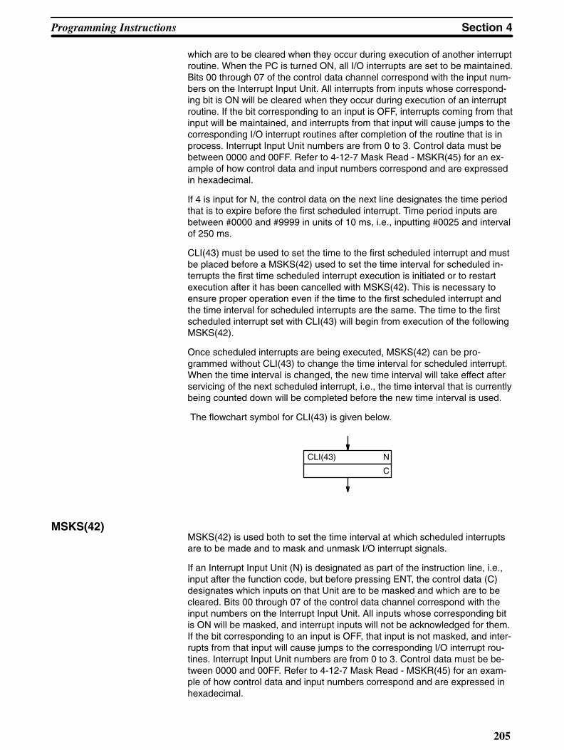
Section 4Programming Instructions
205
which are to be cleared when they occur during execution of another interruptroutine. When the PC is turned ON, all I/O interrupts are set to be maintained.Bits 00 through 07 of the control data channel correspond with the input num-bers on the Interrupt Input Unit. All interrupts from inputs whose correspond-ing bit is ON will be cleared when they occur during execution of an interruptroutine. If the bit corresponding to an input is OFF, interrupts coming from thatinput will be maintained, and interrupts from that input will cause jumps to thecorresponding I/O interrupt routines after completion of the routine that is inprocess. Interrupt Input Unit numbers are from 0 to 3. Control data must bebetween 0000 and 00FF. Refer to 4-12-7 Mask Read - MSKR(45) for an ex-ample of how control data and input numbers correspond and are expressedin hexadecimal.
If 4 is input for N, the control data on the next line designates the time periodthat is to expire before the first scheduled interrupt. Time period inputs arebetween #0000 and #9999 in units of 10 ms, i.e., inputting #0025 and intervalof 250 ms.
CLI(43) must be used to set the time to the first scheduled interrupt and mustbe placed before a MSKS(42) used to set the time interval for scheduled in-terrupts the first time scheduled interrupt execution is initiated or to restartexecution after it has been cancelled with MSKS(42). This is necessary toensure proper operation even if the time to the first scheduled interrupt andthe time interval for scheduled interrupts are the same. The time to the firstscheduled interrupt set with CLI(43) will begin from execution of the followingMSKS(42).
Once scheduled interrupts are being executed, MSKS(42) can be pro-grammed without CLI(43) to change the time interval for scheduled interrupt.When the time interval is changed, the new time interval will take effect afterservicing of the next scheduled interrupt, i.e., the time interval that is currentlybeing counted down will be completed before the new time interval is used.
The flowchart symbol for CLI(43) is given below.
CLI(43) N
C
MSKS(42)MSKS(42) is used both to set the time interval at which scheduled interruptsare to be made and to mask and unmask I/O interrupt signals.
If an Interrupt Input Unit (N) is designated as part of the instruction line, i.e.,input after the function code, but before pressing ENT, the control data (C)designates which inputs on that Unit are to be masked and which are to becleared. Bits 00 through 07 of the control data channel correspond with theinput numbers on the Interrupt Input Unit. All inputs whose corresponding bitis ON will be masked, and interrupt inputs will not be acknowledged for them.If the bit corresponding to an input is OFF, that input is not masked, and inter-rupts from that input will cause jumps to the corresponding I/O interrupt rou-tines. Interrupt Input Unit numbers are from 0 to 3. Control data must be be-tween 0000 and 00FF. Refer to 4-12-7 Mask Read - MSKR(45) for an exam-ple of how control data and input numbers correspond and are expressed inhexadecimal.
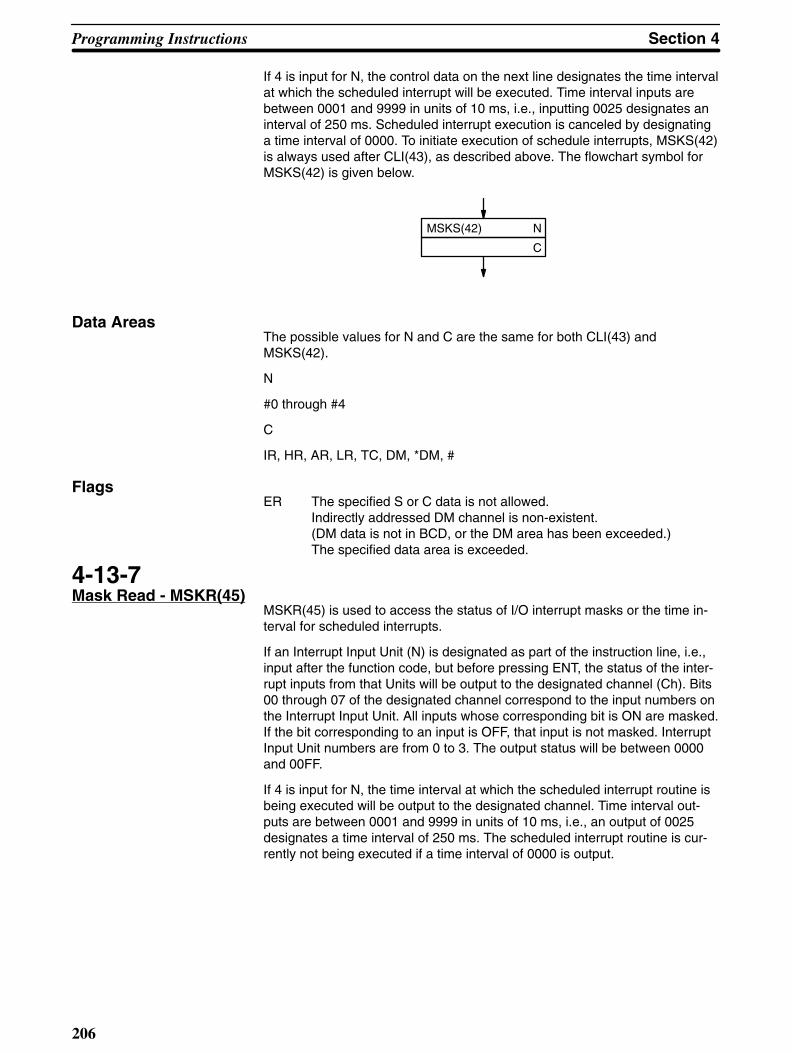
Programming Instructions Section 4
206
If 4 is input for N, the control data on the next line designates the time intervalat which the scheduled interrupt will be executed. Time interval inputs arebetween 0001 and 9999 in units of 10 ms, i.e., inputting 0025 designates aninterval of 250 ms. Scheduled interrupt execution is canceled by designatinga time interval of 0000. To initiate execution of schedule interrupts, MSKS(42)is always used after CLI(43), as described above. The flowchart symbol forMSKS(42) is given below.
MSKS(42) N
C
Data Areas The possible values for N and C are the same for both CLI(43) andMSKS(42).
N
#0 through #4
C
IR, HR, AR, LR, TC, DM, *DM, #
Flags ER The specified S or C data is not allowed.
Indirectly addressed DM channel is non-existent.(DM data is not in BCD, or the DM area has been exceeded.)The specified data area is exceeded.
4-13-7Mask Read - MSKR(45)
MSKR(45) is used to access the status of I/O interrupt masks or the time in-terval for scheduled interrupts.
If an Interrupt Input Unit (N) is designated as part of the instruction line, i.e.,input after the function code, but before pressing ENT, the status of the inter-rupt inputs from that Units will be output to the designated channel (Ch). Bits00 through 07 of the designated channel correspond to the input numbers onthe Interrupt Input Unit. All inputs whose corresponding bit is ON are masked.If the bit corresponding to an input is OFF, that input is not masked. InterruptInput Unit numbers are from 0 to 3. The output status will be between 0000and 00FF.
If 4 is input for N, the time interval at which the scheduled interrupt routine isbeing executed will be output to the designated channel. Time interval out-puts are between 0001 and 9999 in units of 10 ms, i.e., an output of 0025designates a time interval of 250 ms. The scheduled interrupt routine is cur-rently not being executed if a time interval of 0000 is output.

Section 4Programming Instructions
207
Flowchart Symbol
MSKR(45) N
Ch
Data AreasIR, HR, AR, LR, DM, *DM
Flags ER Indirectly addressed DM channel is non-existent.
(DM data is not in BCD, or the DM area has been exceeded.)
Application ExampleThe following program outputs the status of interrupt input from Interrupt InputUnit #0 to DM 0100 and the time interval for scheduled interrupts to HR 20.As shown, interrupt input #3 is currently enabled (not masked) and the rest ofthe interrupt inputs on Unit #0 are masked. The time interval output to HR 20in the example is 100 ms.
100 ms (0010 x 10)
MSKR(45) 0
DM 0100
MSKR(45) 4
HR 20
Interrupt input 7 6 5 4 3 2 1 0
Mask data 1 1 1 1 0 1 1 1
DM0100 0 0 F 7
HR20 0 0 1 0
4-14Special Instructions
Each of the following instructions serves a special purpose that aids in pro-gramming, debugging, or system operation.
The process display instruction, S(47) provides process numbers and mes-sages that aid in monitoring system operation. The failure alarm instructionsFAL(35) and FALS(36) provide error codes and messages that can aid in sys-tem recovery in the event of a system error. Finally, the system definition in-struction FUN(49) provides a means to change program execution parame-ters.
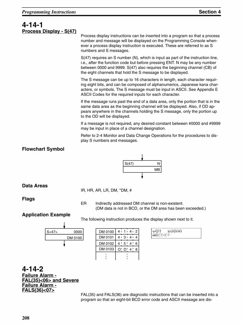
Programming Instructions Section 4
208
4-14-1Process Display - S(47)
Process display instructions can be inserted into a program so that a processnumber and message will be displayed on the Programming Console when-ever a process display instruction is executed. These are referred to as Snumbers and S messages.
S(47) requires an S number (N), which is input as part of the instruction line,i.e., after the function code but before pressing ENT. N may be any numberbetween 0000 and 9999. S(47) also requires the beginning channel (CB) ofthe eight channels that hold the S message to be displayed.
The S message can be up to 16 characters in length, each character requir-ing eight bits, and can be composed of alphanumerics, Japanese kana char-acters, or symbols. The S message must be input in ASCII. See Appendix EASCII Codes for the required inputs for each character.
If the message runs past the end of a data area, only the portion that is in thesame data area as the beginning channel will be displayed. Also, if OD ap-pears anywhere in the channels holding the S message, only the portion upto the OD will be displayed.
If a message is not required, any desired constant between #0000 and #9999may be input in place of a channel designation.
Refer to 2-4 Monitor and Data Change Operations for the procedures to dis-play S numbers and messages.
Flowchart Symbol
S(47) N
MB
Data AreasIR, HR, AR, LR, DM, *DM, #
Flags ER Indirectly addressed DM channel is non-existent.
(DM data is not in BCD, or the DM area has been exceeded.)
Application ExampleThe following instruction produces the display shown next to it.
S<47> 0000
DM 0100
DM 0100
DM 0101
DM 0102
DM 0103
4 1 4 2
4 3 4 4
4 5 4 6
O D 4 8
4-14-2Failure Alarm -FAL(35)<06> and SevereFailure Alarm -FALS(36)<07>
FAL(35) and FALS(36) are diagnostic instructions that can be inserted into aprogram so that an eight-bit BCD error code and ASCII message are dis-

Section 4Programming Instructions
209
played on the Programming Console whenever FAL(35) or FALS(36) is ex-ecuted. The system also outputs FAL(35) and FALS(36) error codes, but theerror codes output by the system are beyond the limit of 99 for programmederror codes.
Both FAL(35) and FALS(36) require an error code (N), which is input as partof the instruction line, i.e., after the function code but before pressing ENT. Nmay be any number between 00 and 99 for FAL(35) and any number be-tween 01 and 99 for FALS(36). FAL(35) 00, however, is used to reset theFAL(35) output area (see below). Each number must be used only once, re-gardless of whether it is used for FAL(35) or for FALS(36).
Both instructions also require the beginning channel (CB) of the eight chan-nels that hold the error message to be displayed. The error message can beup to 16 characters in length, each character requiring eight bits, and can becomposed of alphanumerics, Japanese kana characters, or symbols. Theerror message must be input in ASCII. See Appendix E ASCII Codes for therequired inputs for each character.
If the message runs past the end of a data area, only the portion that is in thesame data area as the beginning channel will be displayed. Also, if OD ap-pears anywhere in the channels holding the error message, only the portionup to the OD will be displayed.
If a message is not required, any desired constant between #0000 and #9999may be input in place of a channel designation.
FAL(35) Output AreasFAL execution lights the warning indicator lamp on the front panel of theCPU, but program execution continues. FALS(36), however, lights the errorindicator lamp and stops the CPU, suspending program execution. FAL(35)and FALS(36) error codes are also output to bits 00 through 07 of SR channel253. This area is also used for system-output error codes.
Resetting FAL(35) Output
All FAL(35) error codes and numbers are retained in memory even thoughonly one is output at a time. To reset the FAL(35) area, execute FAL(35) 00.Each time FAL(35) 00 is executed, another FAL(35) error retained in memoryis output to the FAL(35) area.
Resetting the FALS(36)Output
To reset the FALS(36) output, remove the cause of the FALS(36) error andthen perform Error/Message Read through the Programming Console (See2-2-5 Reading Error Messages and 6-2 Reading Error Messages).
Flowchart Symbols
FALS(36) N
CB
FAL(35) N
CB
Data AreasIR, HR, AR, LR, DM, DM*, #
Flags ER Indirectly addressed DM channel is non-existent.
(DM data is not in BCD, or the DM area has been exceeded.)

!
Programming Instructions Section 4
210
Caution If improper CB designation causes ER to be turned ON, FALS(36) will not be ex-ecuted, and program execution will continue without stopping, in spite of the ex-istence of an emergency, creating a possibly dangerous situation.
Application ExampleThe following program will execute FAL(35) 01, output the message con-tained in DM 0100 through DM 0017, and turn ON output 00500 whenevereither 00000 or 00001 is ON. When both of these inputs are OFF, theFAL(35) area will be cleared and output 00500 is turned OFF. FALS(36) 50will then be executed whenever input 00002 is ON, stopping program execu-tion. If 00002 is OFF, FALS(36) 50 will be skipped.
FALS(36) 50
DM 0100
Yes
No
Yes
No
AND 00000
OR 00001
CJP LBL 100
FAL(35) 00
#0000
OUT NOT 00500
LBL 0010
AND 00002
SKIP NOT 1
LBL 0100
FAL(35) 01
DM 0100
OUT 00500
JMP LBL 0010
Managing FAL(35) andFALS(36)
It is a good practice to make a table of all error codes, error messages, andnotes on all FAL(35) and FALS(36) instructions used in the program.
4-14-3System Definition -FUN<49>
Although system operating parameters are set automatically in the CPU, thesystem definition instruction allows the user access to certain operating pa-rameters. These include selecting power-off interrupt routine execution, ex-panding indirect addressing, changing the scheduler for Unit servicing, inhibit-ing automatic FAL(35) displays, and enabling programming in other thanPROGRAM mode.
FUN<49> must be preceded by a CMP <20> between AR 10 and AR 01(never input CMP(52) for this purpose). This CMP<20> must be placed at
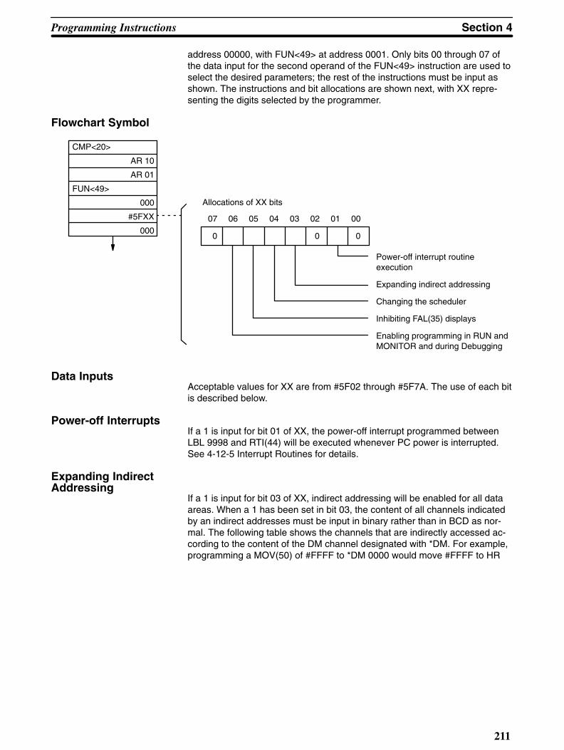
Section 4Programming Instructions
211
address 00000, with FUN<49> at address 0001. Only bits 00 through 07 ofthe data input for the second operand of the FUN<49> instruction are used toselect the desired parameters; the rest of the instructions must be input asshown. The instructions and bit allocations are shown next, with XX repre-senting the digits selected by the programmer.
Flowchart Symbol
CMP<20>
AR 10
AR 01
FUN<49>
000
#5FXX
000
Power-off interrupt routine execution
Expanding indirect addressing
Changing the scheduler
Inhibiting FAL(35) displays
Enabling programming in RUN andMONITOR and during Debugging
0 0 0
07 06 05 04 03 02 01 00
Allocations of XX bits
Data InputsAcceptable values for XX are from #5F02 through #5F7A. The use of each bitis described below.
Power-off InterruptsIf a 1 is input for bit 01 of XX, the power-off interrupt programmed betweenLBL 9998 and RTI(44) will be executed whenever PC power is interrupted.See 4-12-5 Interrupt Routines for details.
Expanding Indirect Addressing
If a 1 is input for bit 03 of XX, indirect addressing will be enabled for all dataareas. When a 1 has been set in bit 03, the content of all channels indicatedby an indirect addresses must be input in binary rather than in BCD as nor-mal. The following table shows the channels that are indirectly accessed ac-cording to the content of the DM channel designated with *DM. For example,programming a MOV(50) of #FFFF to *DM 0000 would move #FFFF to HR
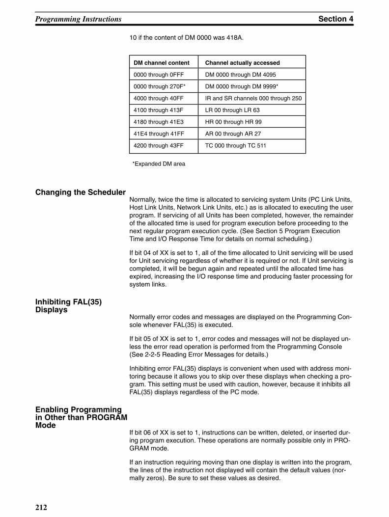
Programming Instructions Section 4
212
10 if the content of DM 0000 was 418A.
*Expanded DM area
DM channel content
0000 through 0FFF
0000 through 270F*
4000 through 40FF
4100 through 413F
4180 through 41E3
41E4 through 41FF
4200 through 43FF
Channel actually accessed
DM 0000 through DM 4095
DM 0000 through DM 9999*
IR and SR channels 000 through 250
LR 00 through LR 63
HR 00 through HR 99
AR 00 through AR 27
TC 000 through TC 511
Changing the SchedulerNormally, twice the time is allocated to servicing system Units (PC Link Units,Host Link Units, Network Link Units, etc.) as is allocated to executing the userprogram. If servicing of all Units has been completed, however, the remainderof the allocated time is used for program execution before proceeding to thenext regular program execution cycle. (See Section 5 Program ExecutionTime and I/O Response Time for details on normal scheduling.)
If bit 04 of XX is set to 1, all of the time allocated to Unit servicing will be usedfor Unit servicing regardless of whether it is required or not. If Unit servicing iscompleted, it will be begun again and repeated until the allocated time hasexpired, increasing the I/O response time and producing faster processing forsystem links.
Inhibiting FAL(35) Displays
Normally error codes and messages are displayed on the Programming Con-sole whenever FAL(35) is executed.
If bit 05 of XX is set to 1, error codes and messages will not be displayed un-less the error read operation is performed from the Programming Console(See 2-2-5 Reading Error Messages for details.)
Inhibiting error FAL(35) displays is convenient when used with address moni-toring because it allows you to skip over these displays when checking a pro-gram. This setting must be used with caution, however, because it inhibits allFAL(35) displays regardless of the PC mode.
Enabling Programmingin Other than PROGRAMMode
If bit 06 of XX is set to 1, instructions can be written, deleted, or inserted dur-ing program execution. These operations are normally possible only in PRO-GRAM mode.
If an instruction requiring moving than one display is written into the program,the lines of the instruction not displayed will contain the default values (nor-mally zeros). Be sure to set these values as desired.

!
Section 4Programming Instructions
213
Caution Changing a program during execution may produce a dangerous situation un-less the consequences of the change for the system being controlled by the pro-gram are fully understood. Change the program only after considering all possi-ble consequences of the change.
When ENT is pressed to write an instruction into memory, program executionwill pause for a maximum of 2 seconds. Confirm that interrupting programexecution for this period of time will not create a dangerous situation beforepressing ENT.
4-15Trace Operations
Trace functions include data and step tracing and make debugging user pro-grams an easier task. To set up and use the data trace functions it is neces-sary to have a FIT or FA Computer (FC-984) with FSS. Data tracing is possi-ble either by using TRSM<45> to mark tracing locations or by specifying atime interval for scheduled tracing.
Data tracing can be used for individual bits or channels in the IR, SR, HR,AR, and LR area, for bits or present values in the TC area, or for channels inthe DM area. Up to 12 bits and 3 channels can be designated for tracing atthe same time.
Step tracing is possible from the Programming Console. See 2-5-3 StepTrace for details. The operation of data tracing using the FIT or FSS is de-scribed in the FIT and FSS Operation Manuals.
Trace Memory Sampling- TRSM<45>
TRSM<45> causes the data bits or channels specified from the FIT or FAComputer to be stored in the Trace Memory of the PC. The specified datamay be recorded either at regular intervals or whenever TRSM<45> is ex-ecuted.
TRSM<45> can be incorporated anywhere in a program and any number oftimes to indicate the locations where sampling is to occur. The data in theTrace Memory can then be monitored through the Programming Console.(See Section 2)
TRSM<45> requires no operands. All settings for TRSM<45> are made fromthe FIT or FA Computer and are not part of the program.
Flowchart Symbol
TRSM(45)
Flags 1812 Trace Complete flag1813 Tracing flag1814 Trace Start bit1815 Sampling Start bitThe Sampling Start bit is set to begin the sampling process, but data is notactually written to the PC’s Trace Memory until the Trace Start bit is turnedON. The Sampling Start bit should not be turned ON from the program, onlyfrom the FIT or FA Computer. The Trace Start bit may be turned ON from the

Programming Instructions Section 4
214
program if desired. The Tracing and Trace Complete flags can be accessedfrom the program as required.
Application ExampleThe following merely outlines the data sampling process. Refer to the FIT orFSS Operation Manual for details.
TRSM<45>
AND 00000
OUTC(00) AR 1814
First, the Sampling Start bit AR 1815 is force-set from the FIT or FA Comput-er (i.e., turned from OFF to ON) to start the sampling process. When input AR1815 turns ON, the trace initiator AR 1814 turns ON, and data is sampledaccording to the delay frequency (assuming it has been set - refer to the FITor FSS Operation Manual).
Monitoring and Trace Memory reading is done from the Programming Con-sole, FIT or FA Computer.
Delay frequency
AR1815
AR1814
AR1813
AR1812
Sampling
4-16File Memory Instructions
File memory instructions all involve the transfer of data between the FileMemory area and the PC memory areas. Since the File Memory area resides

Section 4Programming Instructions
215
on an external File Memory Unit, the instructions described in this section canonly be used if there is a File Memory Unit mounted.
File Memory transfers are done in blocks of 128 channels. File Memory Unitsare available with a capacity of either 1000 or 2000 blocks. The blocks arenumbered from zero.
Exercise care when transferring a very large number of blocks or channelssince this can greatly increase the overall execution time of the program.
AR 19 through AR 21 contain flags and data channels that provide informa-tion of file memory instruction execution. Refer to 3-5 Auxiliary Relay Area -AR for details.
4-16-1File Memory Read -FILR<42>
FILR<42> reads data from the File Memory area in 128-channel block units,and outputs the data to the specified PC destination channels. All destinationchannels must be in the same data area.
Three operands are required: the number of blocks to be transferred (N), thebeginning source block (S), and the beginning destination channel (D). S andN must be in BCD.
If the destination area is too small to accommodate all of the transfer data,only the portion that will fit will be transferred. Data cannot be transferred tothe extended portion of an expanded DM area if an EPROM chip is beingused for Program Memory.
If a power failure occurs during FILR<42> execution, transfer of the blockwhich was being transferred when the power failed will be completed beforeoperation stops.
Flowchart Symbol
FILR<42>
N
S
D
Data AreasN and S
IR, SR, HR, AR, LR, TC, DM, *DM, #
D
IR, HR, AR, LR, TC, DM, *DM
Flags ER File Memory Unit is not mounted.
Content of block data is not in BCD.The specified number of blocks is greater than 999 or 1999.N and/or S is not in BCD.Indirectly addressed DM channel is non-existent.(DM data is not in BCD, or the DM area has been exceeded.)

Programming Instructions Section 4
216
AR Flags
AR 1901 Data Transfer flag (ON during transfer)
AR 1902 Transfer Direction flag (OFF for FILR)
AR 1903 - AR 1906 Error while transfer in progress
AR 20 Ch Total number of transfer blocks (four-digit BCD)
AR 21 Ch Remaining number of blocks to be transferred (four-digit BCD)
4-16-2File Memory Write -FILW<43>
FILW<43> transfers data from a PC memory area to the File Memory area.The data is transferred in 128-channel (block) units.
Three operands are required: the number of blocks to be transferred (N), thebeginning source channel (S), and the beginning destination block (D). D andN must be in BCD.
If a power failure occurs during FILW<43> execution, transfer of the blockwhich was being transferred to when the power failed will be completed be-fore transfer stops.
If the last block of the source transfer area does not have a full 128 channels,the unused channels of the File Memory block will be left empty (0000).
Flowchart Symbol
FILW<43>
N
S
D
Data AreasN
IR, SR, HR, AR, LR, TC, DM, *DM, #
S
IR, SR, HR, AR, LR, TC, DM, *DM
D
IR, HR, AR, LR, TC, DM, *DM, #
Flags ER File Memory Unit is not mounted.
N and/or S is not in BCD.The specified number of blocks is greater than 999 or 1999.Indirectly addressed DM channel is non-existent.(DM data is not in BCD, or the DM area has been exceeded.)

!
Section 4Programming Instructions
217
AR Flags
AR 1901 Data Transfer flag (ON during transfer)
AR 1902 Transfer Direction flag (ON for FILW<43>)
AR 1903 - AR 1906 Error while transfer in progress
AR 20 Ch Total number of transfer blocks (four-digit BCD)
AR 21 Ch Remaining number of blocks to be transferred(four-digit BCD)
Caution If power-off interrupts are being used, data transfer to the File Memory area maynot be completed if a power failure occurs while FILW<43> is being executed. Toensure proper data execution, FILW<43> should be re-executed after restartingthe system.
4-16-3External Program Read -FILP<44>
FLIP<44> reads data stored in the specified File Memory blocks, transfers itto the Program Memory area at the addresses immediately followingFLIP<44>, and then executes the transferred program. The transferred pro-gram data replaces existing program data. Data cannot be transferred whenan EPROM chip is being used for Program Memory.
The transfer data area starts at the specified block and continues to the lastblock in the File Memory area.
The only operand required is the beginning block number (BB) of of the datato be transferred.
Flowchart Symbol
FILP<44>
BB
Data AreasIR, SR, HR, AR, LR, TC, DM, *DM, #
Flags ER ROM is being used for memory.
File Memory Unit is not mounted.Content of B is not in BCD.The specified number of blocks is greater than 999 or 1999.Specified blocks are not program (UM) blocks.

!
Programming Instructions Section 4
218
AR Flags
AR 1901 Data Transfer flag (ON during transfer)
AR 1902 Transfer Direction flag (ON for FLIP<44>)
AR 1903 - AR 1906 Error while transfer in progress
AR 20 Ch Total number of transfer blocks (four-digit BCD)
AR 21 Ch Remaining number of blocks to be transferred(four-digit BCD)
Caution If the File Memory area contains more data than will fit in the designated area ofProgram Memory, ER will be set and FLIP<44> will not be executed.
If the content of any block between the specified block and the last block in theFile Memory is not program data (UM), ER will be set and FLIP<44> will not beexecuted.
If the beginning of a group program (i.e., GN) is rewritten, that group program willbe ended (i.e., placed off standby), regardless of whether it was being executedor awaiting execution before execution FLIP.
When FLIP is used in a group program, that group program will be continued af-ter execution of FLIP until the GE(12) or a jump condition is reached.
When transferring in parts of programs, be sure that all labels, group programends (GE), and other instructions with corresponding instructions in the programbefore FLIP are provided.
Do not transfer in ladder diagram programs (e.g., those for the C1000H orC2000H). These will not execute correctly in the C1000HF.
4-17Intelligent I/OInstructions
The intelligent I/O instructions are used for input/output operations with anIntelligent I/O Unit, such as an ASCII Unit. These instructions allow the PC tosend data to and to receive data from an Intelligent I/O Unit.
4-17-1Intelligent I/O Write -WRIT(87)<87>
WRIT transfers channel data through the I/O channel allocated to an Intelli-gent I/O Unit and sequentially writes the data to the memory area of the Intel-ligent I/O Unit.
Three operands are required: the number of channels to be transferred (N),the beginning PC source channel to be transferred (S), and the channel allo-cated to the Intelligent I/O Unit to receive the transfer (D). Channel D must bebetween 000 and 127 and must be allocated to an Intelligent I/O Unit. All PCchannels to be transferred must be in the same data area.
Completion of the transfer can be confirmed by using EQ. If the Intelligent I/OUnit is busy and unable to receive data, the data will be transferred the nexttime the WRIT instruction is executed.

Section 4Programming Instructions
219
Flowchart Symbol
WRIT(87)
N
S
D
Data AreasN
IR, SR, HR, AR, LR, TC, DM, *DM,#
S
IR, SR, HR, AR, LR, TC, DM, *DM
D
IR (000-127)
Flags ER Destination channel not allocated to an Intelligent I/O Unit.
N is not in BCD.Indirectly addressed DM channel is non-existent.(DM data is not in BCD, or the DM area has been exceeded.)The specified data range exceeds a data area.
EQ OFF while WRIT is in progress; ON when WRIT completes.
Application ExampleProducts are carried along a conveyor to a scale where they are weighed.When 100 products have been weighed, the weights are transferred to theIntelligent I/O Unit through IR channel 003 and then to a printer or other ex-ternal device.
Scale
PH: 00001
Ch 002
DM 0001
DM 0100
Ch 003
ASCII Unit
Indirect addressing through DM 0000 and incrementing of DM 0000 enablesplacing the weights in consecutive channels. A sensor (PH: input 00000) isused to detect each product as it is being weighted, and the weight is inputthrough IR channel 002. The flowchart for this process would be as follows:

Programming Instructions Section 4
220
LBL 30
OUT NOT 00100
OUT 00101
JMP LBL 50
Yes
No
Yes
No
MOV(50)
# 0000
DM 0000
LBL 0010
DIFU(40) 000
00000
WAIT
RPT(37)LBL 10
#0099
AND 25503
LBL 20
WRIT(87)
#0100
DM 0001
003
INC(60)
DM 0000
MOV(50)
002
*DM 0000
CJP LBL 30
AND 25506
CJP LBL 40
JMP LBL 20
LBL 40
OUT NOT 00101
OUT 00100
LBL 50
BSET(73)
#0000
DM 0000
DM 0100
JMP LBL 10
Note that the ER flag is checked and, if an error has occurred, output 00101is turned ON and that the EQ flag is check and, if transfer is completed, out-put 00100 is turned ON. In either case, the DM channels being used for the

Section 4Programming Instructions
221
data are reset to all zeros and the entire process is repeated. If the EQ flagshows that transfer has not been completed, the WRIT(87) is repeated. Out-puts 00100 and 00101 can be used for lighting indicators or other appropriateresponses.
4-17-2Intelligent I/O Read -READ(88)<88>
READ(88) reads data from the memory area of an Intelligent I/O Unit andtransfers it through the channel allocated to the Intelligent I/O Unit to the des-tination channels.
Three operands are required: the number of channels to be transferred (N),the channel allocated to the Intelligent I/O Unit to be transferred from (S), andthe beginning PC destination channel to receive the transfer (D). Channel Smust be between 000 and 127 and must be allocated to an Intelligent I/OUnit. All PC channels to receive the transfer must be in the same data area.
Completion of the transfer can be confirmed by using EQ. If the Intelligent I/OUnit is busy and unable to receive data, the data will be transferred the nexttime the WRIT instruction is executed.
Flowchart Symbol
READ(88)
N
S
D
Data AreasN
IR, SR, HR, AR, LR, TC, DM, *DM, #
S
IR (000 - 127)
D
IR, HR, AR, LR, TC, DM, *DM
Flags ER Source channel is not allocated to an Intelligent I/O Unit.
Indirectly addressed DM channel is non-existent.(DM data is not in BCD, or the DM area has been exceeded.)The specified data range exceeds a data area.
EQ OFF while READ is in progress; ON when READ completes.

Programming Instructions Section 4
222
4-18Network Instructions
The Network instructions are used for communicating with devices on a LANlinked to the PC through a Network Link Unit.
The following flags are used with Network instructions:
25202 - Level 0 Network Data Link Operating flag
25203—Network Error flag
25204—Network Run flag
25205—Level 1 Network Data Link Operating flag
AR 2402—ON when servicing of Network Link or Host Link Unit #1 is stopped
AR 2403 - ON when servicing of Network Link or Host Link Unit #0 is stopped
AR 2413—Network Link or Host Link Unit #1 Connected flag
AR 2414 - Network Link or Host Link Unit #0 Connected flag
4-18-1Send - SEND(90)<90>
SEND(90) sends data to a device linked through a Network Link Unit.
Three operands are required: the beginning source channel to be sent fromthe PC (S), the beginning destination channel on the node to receive thetransmission (D), and the first of the three control channels (C).
The data that will be transmitted is that which is present when SEND(90) isexecuted. Do not change the status of any of this data until the transmissionhas been completed. Use the Network Error and Run Flags to check whetheror not the transmission operation is finished.
Flowchart Symbol
SEND(90)
S
D
C
Control Data for SYSMAC NET
Channel Bits 15 to 8 Bits 7 to 0
C Number of channels: 0000 Hex to 03E8 Hex (0 to 1,000)
C + 1 Bit 14:0: Operating level 11: Operating level 0
Network number: 00 Hex to 7F Hex(0 to 127)
C + 2 Destination port numberNSB: 00, NSU: 01, 02
Destination node number: 00 Hexto 7E Hex (0 to 126)
Set the network number to 00 Hex when sending within the local network.
NSB: Network Service Board
NSU: Network Service Unit

Section 4Programming Instructions
223
The destination port number is normally set to 00. Refer to the Network LinkSystem Operation Manual for details.
SEND(90) takes the specified number of channels of data, starting with thesource beginning channel S, sends them to node N, and writes the data tothe destination channels beginning at channel D.
If the node number is set to 0, data will be sent to all linked PC and computernodes.
Control Data for SYS-MAC LINK
Channel Bits 15 to 12 Bits 11 to 08 Bits 7 to 0
C Number of channels: 0000 Hex to 0100 Hex (0 to 256)
C + 1 Bit 12: Set to 0.
Bit 13:1: Response not required.0: Response required.
Bit 14:1: Operating level 0.0: Operating level 1.
Bit 15: Set to 1.
Number of retries:0 Hex to F Hex (0 to 15)
Response time limit00 Hex to FF Hex(0.1 to 25.4 s)
Note: The responsetime limit will be 2 s ifset to 00 Hex. Therewill be no responsetime limit if set toFF Hex.
C + 2 0 0 Destination nodenumber: 00 Hex to3E Hex (0 to 62)
Number of retries: If there is no response within the set time, the data will beresent for the number of times specified in these bits or until a response isreceived, whichever comes first.
SEND(90) takes the specified number of channels of data, starting with thesource beginning channel S, sends them to node N, and writes the data tothe destination channels beginning at channel D.
If the node number is set to 0, data will be sent to all linked PC and computernodes. There will be no response and no resending regardless of other set-tings.
Data AreasS
IR, SR, HR, AR, LR, TC, DM, *DM
D and C
IR, HR, AR, LR, TC, DM, *DM
FlagsER The specified node number is greater than 126 when using SYSMAC
NET or greater than 62 when using SYSMAC LINK.Indirectly addressed DM channel is non-existent.(DM data is not in BCD, or the DM area has been exceeded.)The data sent overflows a data area.There is no Network Link Unit.
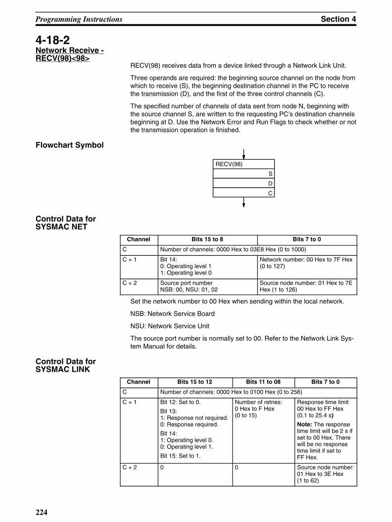
Programming Instructions Section 4
224
4-18-2Network Receive -RECV(98)<98>
RECV(98) receives data from a device linked through a Network Link Unit.
Three operands are required: the beginning source channel on the node fromwhich to receive (S), the beginning destination channel in the PC to receivethe transmission (D), and the first of the three control channels (C).
The specified number of channels of data sent from node N, beginning withthe source channel S, are written to the requesting PC’s destination channelsbeginning at D. Use the Network Error and Run Flags to check whether or notthe transmission operation is finished.
Flowchart Symbol
RECV(98)
S
D
C
Control Data forSYSMAC NET
Channel Bits 15 to 8 Bits 7 to 0
C Number of channels: 0000 Hex to 03E8 Hex (0 to 1000)
C + 1 Bit 14:0: Operating level 11: Operating level 0
Network number: 00 Hex to 7F Hex(0 to 127)
C + 2 Source port numberNSB: 00, NSU: 01, 02
Source node number: 01 Hex to 7EHex (1 to 126)
Set the network number to 00 Hex when sending within the local network.
NSB: Network Service Board
NSU: Network Service Unit
The source port number is normally set to 00. Refer to the Network Link Sys-tem Manual for details.
Control Data for SYSMAC LINK
Channel Bits 15 to 12 Bits 11 to 08 Bits 7 to 0
C Number of channels: 0000 Hex to 0100 Hex (0 to 256)
C + 1 Bit 12: Set to 0.
Bit 13:1: Response not required.0: Response required.
Bit 14:1: Operating level 0.0: Operating level 1.
Bit 15: Set to 1.
Number of retries:0 Hex to F Hex (0 to 15)
Response time limit00 Hex to FF Hex(0.1 to 25.4 s)
Note: The responsetime limit will be 2 s ifset to 00 Hex. Therewill be no responsetime limit if set toFF Hex.
C + 2 0 0 Source node number:01 Hex to 3E Hex (1 to 62)

Section 4Programming Instructions
225
The response returned/not returned setting is normally set to 0 (response re-turned).
Number of retries: If there is no response within the set time, the request tosend will be resent for the number of times specified in these bits or until aresponse is received, whichever comes first.
Data AreasS
IR, SR, HR, AR, LR, TC, DM, *DM
D and C
IR, HR, AR, LR, TC, DM, *DM
FlagsER The specified node number is not in the range 1 to 126 when using
SYSMAC NET or 1 to 62 when using SYSMAC LINK.Indirectly addressed DM channel is non-existent.(DM data is not in BCD, or the DM area has been exceeded.)The data sent overflows a data area.There is no Network Link Unit.
4-18-3About Network Send andReceive Operations
Network send and receive operations are based on command/response pro-cessing. That is, the transmission does not complete until the requestingnode acknowledges a response from the target node. Refer to the relevantSYSMAC LINK Unit or SYSMAC NET Link Unit Operation Manual for detailsabout command/response operations.
A Network send or receive instruction is executed only once; however multi-ple send/receive instructions are permitted. To coordinate the error-free ex-ecution of Network send and receive instructions, use the SR flags describedin the following table.
SR Flag Functions
Network RUN Flag(SR 25204) 0 during SEND/RECV(98) execution (including command
response processing).
Network Error Flag(SR 25203) 0 following normal completion of SEND/RECV(98) (i.e,
after reception of response signal)
1 after an unsuccessful SEND/RECV(98) attempt.Error status is maintained until the next SEND/RECV(98) occurs.
Error types: Timeout Error(command/response time is greater than 1 S)SEND/RECV(98) Data Error

Programming Instructions Section 4
226
Flag Timing
NetworkRun flag
NetworkError flag
Instructionreceived
Transmissioncompleted normally
Instructionreceived
Transmission error
Instruc-tion re-ceived
Application Example :Multiple SEND/RECV(98)
To guarantee the success of multiple SEND/RECV(98) operations, your pro-gram must have exclusive control of the Network Run and Error Flags to con-firm normal completion of transmissions. Always check the Network Run flagto confirm that transmissions are not already in process.
The following program can be used for multiple transmissions usingSEND(90) and RECV(98). Either ten channels of data in the PC starting fromDM 0010 are transmitted to ten channels starting at DM 0020 of node #3(NSB), or sixteen channels of data starting from HR 10 of node 126 (NSB,port #1) are received into sixteen channels in the PC starting at LR 10.

Section 4Programming Instructions
227
LBL 0030
OUT 00201
JMP LBL 40
XFER(72)
#0010
00000
DM 0010
LBL 0020
MOV(50)
#0010
DM 0003
MOV(50)
#0100
DM 0004
Yes
No
LBL 0010
AND 25204
WAIT
AND NOT 00000
CJP LBL 20
MOV(50)
#000A
DM 0000
MOV(50)
#0000
DM 0001
MOV(50)
#0010
DM 0002
SEND(90)
DM 0010
DM 0020
DM 0000
AND 25204
WAIT
AND 25203
OUTC(00) 00200
LBL 40
Network Run flag
Send/receive input
MOV(50)
#017E
DM 0005
RECV(98)
HR 10
LR 10
DM 0003
Control data set in DM0000 through DM 0002
Data from IR channels 000through 009 moved to DM0010 through DM 0019 to setdesired data for the transfer.
Network transmission
Network Error flag
Output 00200 turned ON toindicate an error if NetworkError flag is ON
Yes
No
AND 25204
WAIT
AND 25203
CJP LBL 30
OUT NOT 00201
XFER(72)
#0016
LR 10
DM 0030
JMP LBL 40
Data received in LR 10 through LR25 moved to DM 0030 to 0045 iftransmission is normal
Control data set inDM 0003 throughDM 0005
Output 00201 turnedON to indicate an error

228
Section 5Execution Time and I/O Response Time
One of the most important factors when designing a PC-based control systemis timing. How long does it take the PC to execute all the instructions in theprogram? How long does it take the PC to produce an output in response toan input signal? For accurate system operations, these values must beknown.
Although the execution time of the program can be automatically accessedthrough the Programming Console, it is important to understand the conceptof timing when designing and programming a control system.
The purpose of this section is to define execution time and I/O response timeand to show how to calculate these quantities. Execution times for individualinstructions are listed in 5-3 Instruction Execution Times.
5-1Overall PC Operation
When the PC is turned on, a number of preparations are made before goinginto program execution and Unit servicing. These consist of clearing the IRarea and checking hardware and software, including checking the user pro-gram. If these preparations have been completed normally, the PC moves toactual system control.
System operation is cyclic, as shown below. The operations on the right sideare separated because they are not handled in the same way as instructionexecution and other Unit servicing (see Time Allocations, below). NetworkLink servicing is shown at two different locations because some of it is han-dled at fixed intervals and some of it is handled as a part of normal peripheralservicing (see Time Allocations, below). “Required operations” vary with thesystem and system status.
Servicing Host Link Unit#1or Network link servicing
Network link servicing
Preparations
1 cycle
Required operations
I/O bus check
I/O refreshing
Instruction execution
Peripheral servicing
Servicing Host Link Unit #0
Remote I/O Unit servicing
PC link servicing
Timer processing
Only the first three of these operations are completed each cycle, i.e., it maytake more than one cycle to complete the user program or to complete servic-ing all Units. The next cycle will start operations at the point they were left thelast cycle.

Section 5Execution Time and I/O Response Time
229
The operation cycle of the PC is fixed to a maximum of 48 ms when a Net-work Link Unit is not being used and to a maximum of 72 ms Network LinkUnit is being used.
I/O Unit RefreshingI/O Units mounted to the CPU Rack or to Expansion I/O Racks connecteddirectly to the CPU Rack are refreshed each time instructions are executed,except for 64-point Dynamic I/O Units. Dynamic I/O Units are refreshed every20 ms.
I/O Units mounted to Slave Racks or to Expansion I/O Racks connected toSlave Racks are refreshed during Remote I/O servicing.
Time AllocationsAlthough shown as one step in the execution cycle above, instruction execu-tion and unit servicing is actually broken down into smaller time units asshown below.
Every 5 ms(approx.)
0.5 ms 1.0 ms 0.5 ms 1.0 ms
Instructionexecution
Unitservicing
Instructionexecution
Unitservicing
Remote I/O Unit servicing
PC link servicing
Timer processing
Network link servicing
Every 5 ms(approx.)
Every 20 ms
Every 20 ms
As shown above, Unit servicing is scheduled in two different ways. NormalUnit servicing is performed alternately with instruction execution, whereasRemote I/O, PC link, timer, and some Network link servicing is performed atfixed intervals.
Twice as long is allocated to Unit servicing as is allocated to instruction ex-ecution. If all required Unit servicing for that cycle has been completed, how-ever, the remainder of Unit serving time will be used for instruction executionbefore moving on to the next 0.5-ms portion of instruction execution. Approxi-mately 0.01 ms of each 1-ms portion of the time allocated to Unit servicingwill be required regardless of whether or not the relevant Units are included inthe system. The 1.0-ms portions allocated to Unit servicing sometime requireup to 0.3 ms extra to complete Remote I/O servicing.
One Master Remote I/O Unit is serviced every 5 ms. If there is more than oneMaster in the system, multiply the number of Masters by 5 ms to calculate thetime required to service each, e.g., if eight Master are included, any one Mas-ter will be serviced every 40 ms. This naturally delays I/O response time onSlave Racks.

Execution Time and I/O Response Time Section 5
230
The following tables describe PC operations and provide the number of repe-titions and total serving time per cycle for systems with and without Networklinks.
Systems without Network Links
Operation
Required operations (battery error checks, modechange check, Memory Unit check, output check)
I/O bus check (hardware check)
I/O refreshing (reading Input Unit terminal status toand setting Output Unit terminals according to IR bits)
Instruction execution
Peripheral servicing (Programming Console, FIT, P-ROM Writer, etc.)
Servicing of Host Link Unit #0
Servicing of Host Link Unit #1
Remote I/O Unit servicing
PC link servicing
Timer processing (updating PV)
Repetitions per cycle
1
1
1
32
8
8
8
9 to 10
2 to 3
4 to 5
Total time per cycle
Approx. 1 ms
Approx. 1 ms
Approx. 1 ms
16 ms min.
8 ms max.
8 ms max.
8 ms max.
3 ms max.
3 ms max.
5 ms max.
Systems with Network Links
Operation
Required operations (battery error checks, modechange check, Memory Unit check, output check)
I/O bus check (hardware check)
I/O refreshing (reading Input Unit terminal status to andsetting Output Unit terminals according to IR bits)
Instruction execution
Peripheral servicing (Programming Console, FIT, P-ROM Writer, etc.)
Servicing of Host Link Unit #0
Network link servicing
Remote I/O Unit servicing
PC link servicing
Timer processing (updating PV)
Repetitions per cycle
1
1
1
48
8
8
22
14 to 15
3 to 4
7 to 8
Total time per cycle
Approx. 1 ms
Approx. 1 ms
Approx. 1 ms
24 ms min.
8 ms max.
8 ms max.
22 ms max.
5 ms max.
4 ms max.
8 ms max.
5-2Changing TimeAllocations
Time allocated to Unit servicing can be altered in two ways: by inhibiting serv-icing of certain Units to increase the time used for instruction execution or byforcing the PC to service Units for the entire allocated time.

Section 5Execution Time and I/O Response Time
231
Increasing InstructionExecution
Servicing can be inhibited to increase the time used for instruction executionby setting one or more of six control bits in the AR area. If servicing is inhib-ited, the time normally used for it will be allocated to instruction execution.The six control bits are as follows:
Control bit
AR 2400
AR 2401
AR 2402
AR 2403
AR 2404
AR 2405
Inhibited servicing
PC Link Unit #1
PC Link Unit #0
Host Link Unit #1 or Network Link Unit
Host Link Unit #0
Peripheral devices
I/O refreshing and Remote I/O Units
These control bits are effective only in MONITOR or PROGRAM mode andmust be set from the program. All of these bits are OFF immediately after PCpower is turned on.
Unit Servicing PriorityThe system definition instruction can be used to give priority to Unit servicingover instruction execution thereby increasing the response speed for HostLinks and SYSMAC NET links.
CMP<20>
AR 10
AR 01
FUN<49>
000
#5FXX
000
0 1 0 0
07 06 05 04 03 02 01 00
Allocations of XX bits(The settings for bits not indicated here are de-termined by other system definition settings.)
System Definition Instruction:FUN<49>
Always use CMP<20> and not CMP(52).
Place the above instructions at addresses 00000 and 00001 to give Unit ser-vicing priority over instruction execution.
If the setting above is not made and there is no Unit for Unit servicing 1 (seediagram), servicing will be completed in approx. 0.01 ms, and the remainingtime will be allocated to instruction execution as shown below.

Execution Time and I/O Response Time Section 5
232
Unit servicing 1
Instruction execution Unit servicing 2
0.5 ms 0.5 msIn
stru
ctio
n ex
ecut
ion
1 ms
If the setting above is made and there is no Unit for Unit servicing 1 (see dia-gram below), the remaining time will not be allocated to instruction execution.Unit servicing 2 will be performed before the next instruction is executed.
Unit servicing 2
Unit servicing 1
Unit servicing 3
0.5 ms 0.5 ms
Inst
ruct
ion
exec
utio
n
1 ms
Inst
ruct
ion
exec
utio
n
If AR 2400 to AR 2405 are ON (servicing prohibited) or if AR 2410 is OFF,instruction execution will be given priority even if the system definition instruc-tion above is executed. If AR 2410 is turned ON, the system definition instruc-tion above will become valid, and Unit servicing will be given priority.
5-3Instruction ExecutionTimes
This subsection lists the execution times for all instructions that are availablefor the C1000HF. The conditions which may affect the execution time of agiven instruction are described briefly where relevant.
Both maximum and minimum execution times are listed with the conditionsfor each being given. IL times are the execution time required when the in-struction is in an interlock portion of the program and the interlock executioncondition is OFF.

Section 5Execution Time and I/O Response Time
233
Execution times are expressed in µs except where noted. The “Lines” columnprovides the number of instruction lines required to input the instruction andall required operands.
When step tracing in MONITOR mode, add 31 µs per instructions.
Instruction Execution Times
FunctionCode
Instruction Lines ExecutionTime
Conditions IL
--- And AND 1 5.8 As second or later instruction andusing HR bit
---
13.0 As first instruction and using IR bit
--- Or OR 1 5.2 As second or later instruction andusing HR bit
13.0 As first instruction and using IR bit
--- Load LD 1 6.1 As second or later instruction andusing HR bit
13.0 As first instruction and using IR bit
--- Block AND ANDLD
1 3.3 ---
--- Block OR OR LD 1 3.1 ---
--- Output OUT 2 8.5 Using HR bit 7.0
11.5 Using IR bit 10.6
--- Wait WAIT 1 4.0 No wait produced 3.4
16.2 Wait produced ---
--- Label LBL 2 3.0 --- 3.4
--- Jump JMP 2 11.0 Direct jump to label
29.1 Jump using channel contents aslabel number
--- Conditional Jump
CJP 2 8.0 NO branch (next step)Jump
11.9 YES branch (to label)
--- Timer TIM 3 12.9 After time has expired
43.9 Starting timer with SV in IR channel
--- Counter CNT 4 22.4 After count has expired
42.4 Starting counter with SV in IRchannel
--- Timer/Counter Reset
CNR 2 14.7 For CNT with SV designated withconstant
30.5 For TIM with SV designatedthrough indirect DM address
3 33.6 Resetting stopped TIM or CNT SV
21.4 ms Resetting 10,000 DM channels
--- Shift Register SFT 4 36.8 One-channel shift in HR area 3.4
2.4 ms 128-channel shift in IR area
--- No Operation NOP 1 2.5 --- ---
(00) Conditional Output OUTC 2 9.4 Outputting to HR bit 7.0
12.5 Outputting to IR bit 10.6

Execution Time and I/O Response Time Section 5
234
Instruction Execution Times (Continued)
FunctionCode
ILConditionsExecutionTime
LinesInstruction
(01) AND Group ANDG 2 10.5 ---
11.5 As first instruction
(02) OR Group ORG 2 10.5 As second or later instruction
11.5 As first instruction
(10) Basic Instructions GN 2 2.5 --- 3.4
(11) Group Start GS 2 20.7 ---
(12) Group End GE 2 23.7 When group program is ended
37.7 At end of group program
(13) Group Pause GP 2 17.6 ---
(14) Group Restart GR 2 17.3 ---
(15) Group Off GOFF 2 35.25 min.* When group program is ended
53.45 min.* At end of group program
(16) Group Continue GC 2 20.1 ---
(17) Group Jump GJ 1 14.3 ---
(30) Timer Start TMS 3 15.4 For active timer with SV input asconstant
40.0 For non-active timer with SV des-ignated through indirect DM ad-dress
(31)<92>
Subroutine Definition SBN 2 2.5 --- ---
(32)<91>
Subroutine Entry SBS 2 18.8 --- 3.4
(33)<93>
Return RET 1 13.0 ---
(34) Subroutine Test SBT 2 10.4 ---
(35)<06>
FAL(35) Clear FAL(35) 00
3 15.1 No FAL(35) code present<06> (35) 00
411 FAL(35) code present
Failure Alarm FAL(35)
3 48.8 No message present(35)01—99
60.0 Message designated through indi-rect DM address
(36)<07>
Severe Failure Alarm FALS 3 38.6 No message present 4.7<07>
51.1 Message designated through indi-rect DM address
(37) Repeat RPT 3 15.6 Last repetition 3.4
19.8 First repetition
(38)<02>
Interlock IL 2 12.2 --- ---
(39)<03>
Interlock Clear ILC 1 3.3 ---
(40)<13>
Differentiation Up DIFU 3 10.8 Using HR bit<13>
15.8 Using IR channel
(41)<14>
Differentiation Down DIFD 3 11.0 Using HR bit<14>
15.5 Using IR channel
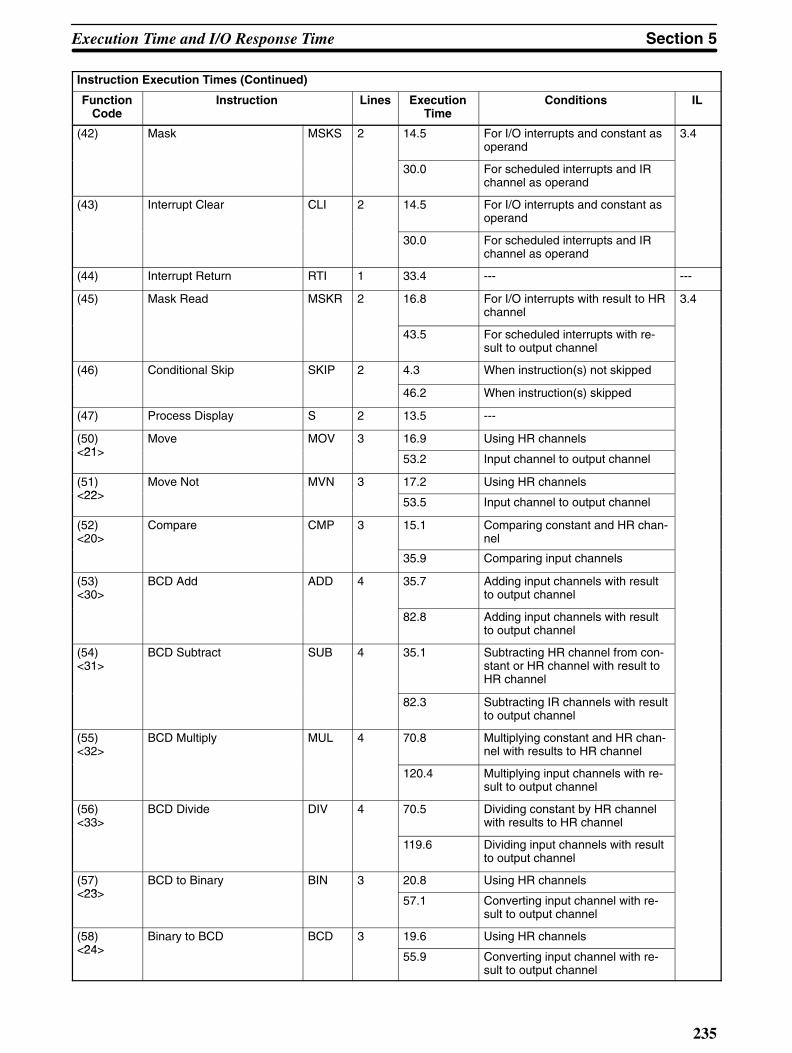
Section 5Execution Time and I/O Response Time
235
Instruction Execution Times (Continued)
FunctionCode
ILConditionsExecutionTime
LinesInstruction
(42) Mask MSKS 2 14.5 For I/O interrupts and constant asoperand
3.4
30.0 For scheduled interrupts and IRchannel as operand
(43) Interrupt Clear CLI 2 14.5 For I/O interrupts and constant asoperand
30.0 For scheduled interrupts and IRchannel as operand
(44) Interrupt Return RTI 1 33.4 --- ---
(45) Mask Read MSKR 2 16.8 For I/O interrupts with result to HRchannel
3.4
43.5 For scheduled interrupts with re-sult to output channel
(46) Conditional Skip SKIP 2 4.3 When instruction(s) not skipped
46.2 When instruction(s) skipped
(47) Process Display S 2 13.5 ---
(50)<21>
Move MOV 3 16.9 Using HR channels<21>
53.2 Input channel to output channel
(51)<22>
Move Not MVN 3 17.2 Using HR channels<22>
53.5 Input channel to output channel
(52)<20>
Compare CMP 3 15.1 Comparing constant and HR chan-nel
35.9 Comparing input channels
(53)<30>
BCD Add ADD 4 35.7 Adding input channels with resultto output channel
82.8 Adding input channels with resultto output channel
(54)<31>
BCD Subtract SUB 4 35.1 Subtracting HR channel from con-stant or HR channel with result toHR channel
82.3 Subtracting IR channels with resultto output channel
(55)<32>
BCD Multiply MUL 4 70.8 Multiplying constant and HR chan-nel with results to HR channel
120.4 Multiplying input channels with re-sult to output channel
(56)<33>
BCD Divide DIV 4 70.5 Dividing constant by HR channelwith results to HR channel
119.6 Dividing input channels with resultto output channel
(57)<23>
BCD to Binary BIN 3 20.8 Using HR channels<23>
57.1 Converting input channel with re-sult to output channel
(58)<24>
Binary to BCD BCD 3 19.6 Using HR channels<24>
55.9 Converting input channel with re-sult to output channel

Execution Time and I/O Response Time Section 5
236
Instruction Execution Times (Continued)
FunctionCode
ILConditionsExecutionTime
LinesInstruction
(59) Branch for Zero BRZ 2 13.3 Using HR channel, no jump 3.4
46.8 Using input channel with jump toinput-channel designated label
(60)<38>
Increment INC 2 21.6 Incrementing non-I/O channel<38>
47.0 Incrementing output channel
(61)<39>
Decrement DEC 2 20.7 Using any but I/O channel<39>
46.1 Using output channel
(62)<26>
Arithmetic Shift Right ASR 2 15.9 Using any but I/O channel<26>
41.3 Using output channel
(63)<25>
Arithmetic Shift Left ASL 2 15.9 Using any but I/O channel<25>
41.3 Using output channel
(64)<72>
Square Root ROOT 3 100.0 Using HR channels<72>
133.9 Using input channels with result tooutput channel
(65)<34>
Logical AND ANDW 4 21.8 Using HR channels<34>
69.0 Using input channels with result tooutput channel
(66)<35>
Logical OR ORW 4 21.5 Using HR channels<35>
68.7 Using input channels with result tooutput channel
(67)<36>
Exclusive OR XORW 4 21.9 Using HR channels<36>
69.0 Using input channels with result tooutput channel
(68)<37>
Exclusive NOR XNRW 4 21.9 Using HR channels<37>
69.0 Using input channels with result tooutput channel
(69)<28>
Rotate Right ROR 2 16.7 Using HR channel<28>
41.9 Using output channel
(70)<27>
Rotate Left ROL 2 16.7 Using HR channel<27>
42.2 Using output channel
(71)<29>
Complement COM 2 13.5 Using HR channel<29>
39.0 Using output channel
(72)<70>
Block Transfer XFER 4 49.0 Constant to HR channel<70>
24.4 ms Writing 9999 DM channels to indi-rectly address destination
(73)<71>
Block Set BSET 4 36.1 Constant to HR channel<71>
21.3 ms Writing 9999 DM channels usingindirectly addressed source anddestination
(74)<73>
Data Exchange XCHG 3 19.7 Exchanging HR channels<73>
30.0 Exchanging output channels
(75)<74>
One Digit Shift Left SLD 3 37.8 Shifting HR channel<74>
18.5 ms Shifting 10,000 DM channels
(76)<75>
One Digit Shift Right SRD 3 37.8 Shifting HR channel<75>
18.5 ms Shifting 10,000 DM channels

Section 5Execution Time and I/O Response Time
237
Instruction Execution Times (Continued)
FunctionCode
ILConditionsExecutionTime
LinesInstruction
(77)<76>
4 to 16 Decoder MLPX 4 35.5 Decoding HR channel to HR chan-nel
3.4
105.0 Decoding input channel to outputchannel
(78)<77>
Encoder DMPX 4 41.9 Encoding HR channel to HR chan-nel
107.8 Encoding input channel to outputchannel
(79)<78>
Seven-Segment Decoder SDEC 4 39.4 Decoding HR channel to HR chan-nel
104.9 Decoding input channel to outputchannel
(80) Multi-output Timer MTIM 4 59.7 Using HR channels
191.7 Using I/O channels
(87)<87>
Intelligent I/O Write WRIT 4 83.2 Writing HR channel<87>
1.7 ms Writing 255 DM channels
(88)<88>
Intelligent I/O Read READ 4 81.0 Reading HR channel<88>
1.3 ms Reading 255 DM channels
(90)<90>
Send SEND 4 107.7 Sending HR channel<90>
3.5 ms Sending 1,000 DM channels
(94)<16>
Word Shift WSFT 4 37.9 Shifting constant to HR channel<16>
22.0 ms Shifting input channel to 10,000DM channels
(95)<40>
Set Carry STC 1 5.2 ---
(96)<41>
Clear Carry CLC 1 4.9 ---
(98)<98>
SYSNET Receive RECV 4 58.3 Receiving HR channel
104.0 Receiving input channel
<12> Reversible Counter CNTR 3 21.6 During operation with no incre-ment or decrement
49.0 First execution with SV designatedthrough input channel
<42> File Memory Read FILR 4 2.9 ms One block
177 ms 79 blocks
<43> File Memory Write FILW 4 3.0 ms One block
171 ms 79 blocks
<44> External Program Read FILP 2 48.6 ms One block
1.15 s 256 blocks
<45> Trace Memory Sampling TRSM 1 4.0 When not tracing ---
94.0 When tracing
<49> System Definition FUN 4 2.5 3.4
<50> Binary Addition ADB 4 24.2 Using HR channels
65.6 Using input channels with result tooutput channel

Execution Time and I/O Response Time Section 5
238
Instruction Execution Times (Continued)
FunctionCode
ILConditionsExecutionTime
LinesInstruction
<51> Binary Subtraction SBB 4 24.2 Using HR channels 3.4
65.9 Using input channels with result tooutput channel
<52> Binary Multiplication MLB 4 47.9 Using HR channels
92.1 Using input channels with result tooutput channel
<53> Binary Division DVB 4 56.7 Using HR channels
110.1 Using input channels with result tooutput channel
<54> Double BCD Add ADDL 4 79.0 Using HR channels
162.0 Using input channels with result tooutput channel
<55> Double BCD Subtract SUBL 4 80.6 Using HR channels
161.5 Using input channels with result tooutput channel
<56> Double BCD Multiply MULL 4 203.5 Using HR channels
283.0 Using input channels with result tooutput channel
<57> Double BCD Divide DIVL 4 192.5 Using HR channels
287.2 Using input channels with result tooutput channel
<58> BCD to Double Binary BINL 3 39.7 Converting HR channel to HRchannel
96.4 Converting input channel to outputchannel
<59> Double Binary to DoubleBCD
BCDL 3 44.2 Converting HR channel to HRchannel
99.7 Converting input channel to outputchannel
<60> Compare Long CMPL 3 25.7 Using HR channels
80.3 Comparing input channels with re-sult to output channel
<61> Binary Increment INCB 2 13.5 Incrementing any but output chan-nel
38.9 Incrementing output channel
<62> Binary Decrement DECB 2 13.5 Decrementing any but outputchannel
38.9 Decrementing output channel
<67> Bit Counter BCNT 4 44.7 Counting HR channel with result toHR channel
33.6 ms Counting 9999 indirectly ad-dressed DM channels with resultto output channel
<68> Block Compare BCMP 4 62.1 Using HR channels
594.9 Comparing input channels with re-sult to output channel

Section 5Execution Time and I/O Response Time
239
Instruction Execution Times (Continued)
FunctionCode
ILConditionsExecutionTime
LinesInstruction
<69> Numeric Conversions FUN 4 96.4 Computing sine or cosine 3.4
1.4 ms Using maximum size table andchannel operand
<79> Floating Point Divide FDIV 4 58.5 Using HR channels
265.0 Dividing input channels with 0 re-sult to output channel
<80> Single Channel Distribution DIST 4 30.0 Using HR channels
66.8 Moving input channel to outputchannel with input-channel desig-nation for offset
<81> Data Collection COLL 4 31.7 Using HR channels
81.6 Moving input channel to outputchannel with input-channel desig-nation for offset
<82> Move Bit MOVB 4 34.9 Moving HR channel to HR channel
82.1 Moving input channel to outputchannel
<83> Move Digit MOVD 4 30.7 Moving HR channel to HR channel
77.9 Moving input channel to outputchannel
<84> Reversible Shift Register SFTR 4 40.5 One-channel HR shift with HRcontrol data
15.4 ms 10,000-channel DM shift with inputchannel IR control data
<85> Table Compare TCMP 4 64.5 Comparing HR channels
335.3 Comparing input channels
<86> ASCII Code Conversion ASC 41.5 Converting HR channel to HRchannel
116.9 Converting input channel to outputchannel

Execution Time and I/O Response Time Section 5
240
5-4I/O Response Time
Response time is the time it takes for the PC to output a control signal after ithas received an input signal. How long it takes to respond depends on factorssuch as the system configuration and when the CPU receives the input signalrelative to program execution. For more details on response times for config-urations involving the systems below, refer to the appropriate systems manu-al as indicated.
PC to Remote I/O Systems: Remote I/O Systems Operation Manual
PC Link Systems: PC Link Systems Operation Manual
Host Link Systems: Host Link Systems Operation Manual
An input will naturally not produce an output unless both an input instructionand an output instruction are executed for it. In the following calculations Xindicates the time that expires between the receiving the input and executingan input instruction for it. Y indicates the time from beginning execution of theinput instruction until an output instruction is executed (i.e., the program ex-ecution time for all instructions from the input instruction through the outputinstruction).
5-4-1CPU Rack ResponseTimes
The following equations can be used to compute the maximum and minimumresponse times for I/O Units mounted to the CPU Rack or to an ExpansionI/O Rack connected directly to the CPU Rack. The timing charts serve to ex-plain the various elements of the equations.
Normal I/O Units• Minimum I/O Response Time
The minimum response time occurs when X, the input ON-delay time, is zerobecause the instruction using the input was processed immediately after theinput was received (i.e., after the delay time had expired).
Input instructionexecuted.
Output instructionexecuted.
PC
Input ON-delay time
Input
Output
Minimum I/O response time
Output ON-delay time
Y
Minimum I/O Response Time = Input ON-delay time + Y + Output ON delaytime

Section 5Execution Time and I/O Response Time
241
• Maximum I/O Response Time
PC
Input ON-delay time
Input
Output
Minimum I/O response time
Output ON-delay time
Y
Input instructionexecuted.
Output instructionexecuted.
X
Maximum I/O Response Time = Input ON-delay time + X + Y + Output ONdelay time
64-Point I/O UnitsIn the following calculations [Y/20] indicates the truncated integer of Y dividedby 20.
• Minimum I/O Response Time
Y
PC
Input ON-delay time
Input
Output
Minimum I/O response time
Output ON-delay time
Input instructionexecuted.
Output instructionexecuted.
Dynamic I/OUnit refreshing
Minimum I/O response time = Input ON-delay time + (([Y/20] +1) x 20) + Out-put ON-delay time
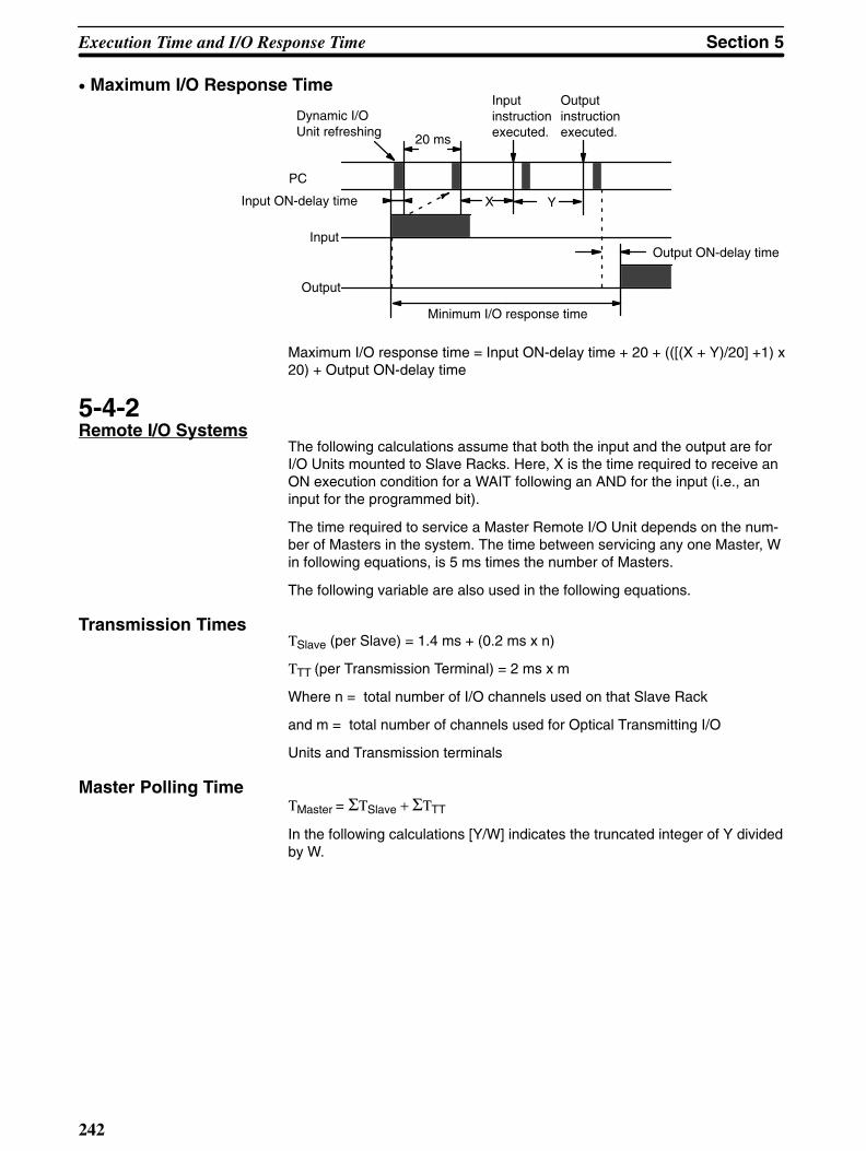
Execution Time and I/O Response Time Section 5
242
• Maximum I/O Response Time
X Y
PC
Input ON-delay time
Input
Output
Minimum I/O response time
Output ON-delay time
Input instructionexecuted.
Output instructionexecuted.
Dynamic I/OUnit refreshing
20 ms
Maximum I/O response time = Input ON-delay time + 20 + (([(X + Y)/20] +1) x20) + Output ON-delay time
5-4-2Remote I/O Systems
The following calculations assume that both the input and the output are forI/O Units mounted to Slave Racks. Here, X is the time required to receive anON execution condition for a WAIT following an AND for the input (i.e., aninput for the programmed bit).
The time required to service a Master Remote I/O Unit depends on the num-ber of Masters in the system. The time between servicing any one Master, Win following equations, is 5 ms times the number of Masters.
The following variable are also used in the following equations.
Transmission TimesΤSlave (per Slave) = 1.4 ms + (0.2 ms x n)
ΤTT (per Transmission Terminal) = 2 ms x m
Where n = total number of I/O channels used on that Slave Rack
and m = total number of channels used for Optical Transmitting I/O
Units and Transmission terminals
Master Polling TimeΤMaster = ΣΤSlave + ΣΤTT
In the following calculations [Y/W] indicates the truncated integer of Y dividedby W.

Section 5Execution Time and I/O Response Time
243
Minimum ResponseTime
Minimum Response time
Remote I/O servicing
W
Y
PC
Master
Transmissiontime
Transmissiontime
SlaveInput ON-delay time
Output ON-delay timeInput
Output
Minimum Response time = Input ON-delay time + (([Y/W] +1) x W) + OutputON-delay time
Maximum ResponseTime
Output ON-delay time
X+Y
W
Remote I/O servicing
PC
Master
Master polling time Master polling time
Transmission time
Slave
Input
Output
Input ON-delay time
Maximum Response time = Input ON-delay time + W (([(X + Y)/W] +1) x W) +(Master polling time + transmission time) x 2 + Output ON-delay time
5-4-3PC Link Systems
When PC links are serviced, the following operations are performed in order.
1.Data exchange between link buffer in PC Link Unit and PC link buffer in PC
2.Data exchange between PC link buffer in PC and LR area
Each PC Link Unit is serviced every 20 ms.
The PC link transmission time is 2.5 ms.

Execution Time and I/O Response Time Section 5
244
The following equations show calculation of the time required from an outputfrom the LR area of the PC of PC Link Unit #0 to an input in the LR area ofthe PC of PC Link Unit #1.
Minimum ResponseTime
PC ofPC LinkUnit #0
PC LinkUnit
LR area
PC linkbuffer
Linkbuffer
PC
20 ms PC link processing cycle
PC link service timeTransmissiontime
PC ofPC LinkUnit #7
PC LinkUnit
PC
LR area
PC linkbuffer
Linkbuffer
PC link transmission
Minimum Response time = 20 ms + Transmission time + 3 x PC link servicetime
Maximum ResponseTime
The PC link cycle time is the time required for one PC Link Subsystem fromthe time a particular PC Link Unit is serviced until the same Unit is servicedagain. This time equals 5 ms plus 2.5 ms times the number of PC Link Unitsin the PC Link Subsystem, where 5 ms is for overhead processing and 2.5 isthe transmission time per Unit.

Section 5Execution Time and I/O Response Time
245
V is 20 ms unless the PC cycle time is less than 20 ms and PC Link Unit linkbuffer data cannot be transferred to the PC link buffer in the PC within thistime, in which case it is 40 ms.
PC link cycle time
PC ofPC LinkUnit #0
PC LinkUnit
LR area
PC linkbuffer
Linkbuffer
PC
20 ms PC link processing cycle
PC link servicetime
Transmission time
PC ofPC LinkUnit #7
PC LinkUnit
PC
LR area
PC linkbuffer
Linkbuffer
PC link transmission
Maximum Response time = 20 ms + PC link cycle time + Transmission time +V + 3 x PC link service time
5-4-4Host Link Systems
The following equations show calculation of the time required from an outputof a command from the host computer until a response to the command isreceived.
In the following equations, U is the Host Link service interval and equals 48/8,or 6 ms, if there is no Network link in the system, and 72/8, or 9 ms, is thereis a Network link. “n” is the number of execution processing times required toprocess the command. “2n” is required in the equations because data trans-fer between the PC and Host Link Unit buffer is executed alternately with ex-ecution processing.
Command and response processing in the Host Link Unit varies, but togetherrequired a maximum of approximately 10 ms.
A minimum of three service times are required for the PC to receive the hostcomputer command, process it, and return a response. Processing host com-puter commands sometimes requires more than one service time.

Execution Time and I/O Response Time Section 5
246
Minimum ResponseTime
Execution pro-cessing time
Hostcomputer
Buffer in HostLink Unit
PC
Command
Command
Command
Response
Response
Response
UU
Minimum Response time = Command transmission time + command pro-cessing time + 2U + U x 2n + Host Link servicing time + Host Link responseprocessing time + response transmission time
Maximum ResponseTime
The maximum response time can be lengthened by 2U by reception timing(i.e., if Host Link servicing has just been completed).
Command Response
Execution processing time
Command
Host computer
Buffer in HostLink Unit
PC
Command
Command
Response
Response
Maximum Response time = Command transmission time + command pro-cessing time + 4U + U x 2n + Host Link servicing time + Host Link responseprocessing time + response transmission time
Command and ResponseTransmission Times
The following transmission times are required at a baud rate of 9,600 bpswith the given command and response formats to read I/O bits from the IRarea.
@ RR 0001Command
Response @ ××××
××
×× RR
0000
0000
FCS
FCS
Transmission time
18.3 ms
18.3 ms
Calculation ExampleThe following calculations show the minimum and maximum response timesunder the conditions described above, as well as the following conditions: thesystem does not include a Network Link Unit; U is 6 ms, the Host Link servicetime is 1 ms, and the combined Host Link command and response process-ing time is 5 ms.
Minimum response time = 18.3 + 2 x 6 +1 + 5 + 18.3 = 54.6 ms
Maximum response time = 18.3 + 4 x 6 +1 + 5 + 18.3 = 62.5 ms

247
SECTION 6Error Messages and Troubleshooting
The C1000HF has self-diagnostic functions to identify many types of abnor-mal system conditions. These functions minimize downtime and enable quick,smooth error correction.
The error light on the front panel of the Programming Console indicates hard-ware errors such as CPU, I/O Unit, and Remote I/O Unit malfunctions. Thewarning light indicates such things as battery error or user-defined errors.
In addition, the Programming Console acts as a monitor by displaying expliciterror messages and FAL error codes.
This section lists the error messages displayed on the LCD of the Program-ming Console.
6-1Programmed Alarms andError Messages
Use the diagnostic instructions, FAL(35) and FALS(36), to program displaysof error codes and messages when user-defined error conditions arise. Notethat it is entirely up to the user to decide the conditions under which aFAL(35) or FALS(36) is executed. Refer to 4-14-2 Failure Alarm -FAL(35)<06> and Severe Failure Alarm - FALS(36)<07> for details about howto use these diagnostic instructions in your program.
When “FAL(35) N” is executed, the value of the FAL(35) error code “N” isstored as a 2-digit BCD code in the SR area (See 3-3-4 FAL Error Code Out-put Area). FAL(35) also lights the warning indicator on the front panel of theCPU.
AND XXXXX
Yes
No
Input indicating abnormal condition
Beginning addressof message
LBL
FAL(35) 01 to 99
DM 0000
CJP

Error Messages and Troubleshooting Section 6
248
When FALS(36) is executed, the error indicator on the front panel of the CPUlights and system operations are halted.
Yes
No
AND XXXXX
Beginning addressof message
LBL
FALS(36) 01 to 99
DM 0100
CJP
Input indicating emergency
To resume system operations, determine the cause of the error, make correc-tions, then clear the error. FALS(36) errors must be cleared from the Pro-gramming Console in PROGRAM mode using the procedure given in 6-2Reading and Clearing Errors and Messages.
FAL error codes 01 to 99 are assigned as desired by the programmer.FAL(35) 00 is reserved for clearing other FAL codes and messages present inthe system.
6-2Reading and ClearingErrors and Messages
To display an error code or a message on the Programming Console, pressCLR, MONTR, FUN, and ENT. (See 2-2-5 Reading Error Messages for moreinformation.)
To display the next error or message, press ENT again. If the system is inPROGRAM mode, pressing ENT clears the error message and code thatwere being displayed. Continue pressing ENT, taking note of the errors ormessages, until all have been cleared and the message “ERR CHK OK” isdisplayed. Then correct each of the errors.
The buzzer will sound if the system cannot clear an error code or a messagefor some reason. If this situation arises, remove the cause of the error andthen display and clear the error again.
The asterisks in the error messages on the following pages indicate variablenumerals in actual displays.

Not operating
Fatal
means that the LED is lit, that the LED is not lit.
means that the LED being lit or not makes no difference.
Section 6Error Messages and Troubleshooting
249
6-3System Errors
Error CPU Leds
State Item Error Display Power Run Error Warning LoadOFF
Waiting for start in-put
Waiting for RemoteI/O Units
Power interruption
CPU error
Memory error
Program error
I/O bus error
I/O table overflow
Invalid I/O table
System error
Jump error
RTI error

Error Messages and Troubleshooting Section 6
250
Runoutput
SRArea
ErrorCode
Probable cause of error Correction
Start input of CPU Power Unit is OFF. Short-circuit the start input terminal of the CPUPower Unit.
OFFRemote I/O Unit power off.Terminator not set or two terminators setfor same Subsystem.
Check the power supply and the terminator set-tings.
OFFPower has been cut off for at least 10ms.
Check voltage source and power lines. Try topower-up again.
OFFWatchdog timer 130 ms or more. In PROGRAM mode, power-up the system again.
Check the user program again.
OFF F1Memory Unit is incorrectly mounted ormissing. Memory parity error occurred.Improper instruction.
Do a program check and fix the error.Make sure that the Memory Unit is mounted cor-rectly.Check that the battery is inserted properly.Clear error after fixing.
OFF F0Capacity of Program Memory area ex-ceeded.
Check the program
OFF(Note)
Failure is in the bus line between theCPU Rack and the Expansion I/O Racks.
Check the number of points with I/O Table Read,and use I/O Table Register to match the registertable to the actual table.Clear error after fixing.
OFFE1
Same Unit number assigned to morethan one Special I/O Unit.I/O limitations exceeded when usingCPU02.
Check the Unit numbers with I/O Table Read.With CPU02 use only slots 0 to 4 on CPU Rackand no Masters.Use CPU01 or place I/O Units on Expansion I/ORack.
OFF E0I/O Units have been replaced and theregistered I/O table does not agree withthe I/O Units actually mounted to the PC.
Check the I/O table with I/O Table Verify, and useI/O Table Register to match the registered tableto the actual table.
OFF 01 to99
FALS(36) has been executed by the pro-gram.
Check the program.
OFF F2Label for jump not in program. Check the program.
OFF F4RTI used for other than interrupt proc-essing.
Check the program.

Non-fatal
means that the LED is lit,
means that the LED being lit or not makes no difference.
Section 6Error Messages and Troubleshooting
251
Error CPU Leds
State Item Error Display Power Run Error Warning LoadOFF
System error
I/O table verificationerror
Remote I/O errorRemoteI.O Unit #
Battery error
Host link error
PC link error
Indirect jump error
DM address error
* Load cut-off error

Error Messages and Troubleshooting Section 6
252
Runoutput
SRArea
ErrorCode
Probable cause of error Correction
ON---
01 to99
FAL(35) has been executed by the pro-gram.
Check the program.
ON 25310ON
E7The registered I/O table does not agreewith the actual I/O Units.
Check the I/O Unit connections with I/O Table Verify,and set the I/O Units properly. Then use I/O TableRegister to match the registered table to the actualtable.
ON seeRef. #1below
B0 toB7(Note)
A failure has occurred in the transmissionline between a Master and Slave.
Check the transmission line between the Masterand Slave.
ON seeRef. #2below
F7Battery is bad or is not installed properly. Check battery connections, or replace battery.
ON seeRef. #3below
--- An error between the Host Link Units. Refer to the Host Link Systems Operation Manual.
ON seeRef. #4below
--- An error occurred in the PC Link Unit. Refer to the PC Link Systems Operation Manual.
ON 25309ON
F9Indirectly addressed label out of range. Check the program.
ON 25315ON
F8 DM address out of range.Indirectly addressed DM address is not inBCD or is out of range.
Check the program.
ON 25215ON
The Output OFF bit is ON (SR 25215).
Ref. #1: 25312 ONRefer to Ch 251
Ref. #2: 25308 ONFile Memory Unit Battery Alarm flag AR 1907 ON.
Ref. #3: For Rack-mounting Unit #0, 25311 ONFor Rack-mounting Unit #1, 25206 ON
Ref. #4: See SR 247 to 250
Note: “0 to 7” is the number of the Remote I/O Master Unit.
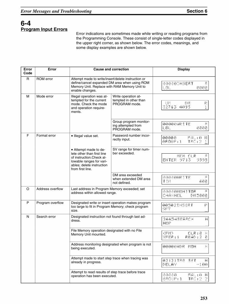
Section 6Error Messages and Troubleshooting
253
6-4Program Input Errors
Error indications are sometimes made while writing or reading programs fromthe Programming Console. These consist of single-letter codes displayed inthe upper right corner, as shown below. The error codes, meanings, andsome display examples are shown below.
ErrorCode
Error Cause and correction Display
R ROM error Attempt made to write/insert/delete instruction ordefine/cancel expanded DM area when using ROMMemory Unit. Replace with RAM Memory Unit toenable changes.
M Mode error Illegal operation was at-tempted for the currentmode. Check the modeand operation require-ments.
Write operation at-tempted in other thanPROGRAM mode.
Group program monitor-ing attempted fromPROGRAM mode.
F Format error • Illegal value set. Password number incor-rectly input.
• Attempt made to de-lete other than first lineof instruction.Check al-lowable ranges for vari-ables; delete instructionfrom first line.
SV range for timer num-ber exceeded.
DM area exceededwhen extended DM areanot defined.
O Address overflow Last address in Program Memory exceeded; setaddress within allowed range.
P Program overflow Designated write or insert operation makes programtoo large to fit in Program Memory; check programsize.
N Search error Designated instruction not found through last ad-dress.
File Memory operation designated with no FileMemory Unit mounted.
Address monitoring designated when program is notbeing executed.
Attempt made to start step trace when tracing wasalready in progress.
Attempt to read results of step trace before traceoperation has been executed.

Error Messages and Troubleshooting Section 6
254
6-5Program Errors
The following error messages indicate a problem with the structure or syntaxof the program.
Error Message Probable cause and correction
The program has been destroyed. Write the program into memory again.
The program has been destroyed. Write the program into memory again.
Instructions have not been combined properly:• LD, AND, OR, AND LD, and/or OR LD.• WAIT, WAIT NOT, CJP, CJP NOT, SKIP(46), SKIP(46) NOT, OUTC(00) and/orOUTC(00) NOT with one of the following: AND, OR, LD, TIM, CNT, CNTR<12>,DIFU(40), DIFD(41).
• A channel between DM 4096 and DM 9999 has been designated as an operand whenexpanded DM area has not been designated.• The variable operand data specified is incorrect. Check the operand data range for each instruction.
The I/O table cannot be registered, possibly because of too many remote I/O points,duplicated Unit numbers for Optical Transmitting I/O Units or Transmission Terminals,no Remote I/O Units, or too many I/O points in system; check all I/O points.
The same label number has been assigned twice; use LBL only once with each labelnumber.
The corresponding LBL for a given JMP, CJP, etc. does not exist; correct the programto define all labels used.
GN has been used twice with the same group program number; use GN only once witheach number.
GN has not been used to define a group program number used in GS, GE, GP, GR,GOFF or GC; correct the program to define all group program numbers used.
SBN has been used twice with the same subroutine number; use SBN only once witheach number.
SBN has not been used to define a subroutine number used in SBS or SBT; correct theprogram to define all subroutine numbers used.
SBN and RET have not been used in pairs or a GN has been used between SBN andRET; correct the program to remove unpaired SBN or RET or remove group programinstruction from middle of subroutine.

Section 6Error Messages and Troubleshooting
255
Error Message Probable cause and correction
IL and ILC have not been used in pairs; correct the program to remove unpaired IL orILC.
Same timer/counter number (TC address) has been used twice for TIM, CNT, and/orCNTR; correct the program to remove duplication.
6-6File Memory andCassette Tape Errors
The following messages indicate errors involving File Memory Unit or cas-sette tape operations.
File Memory Errors
Error Message Probable cause and correction
Writing has been attempted to a write-protected portion of the File Memory Unit or datato be read from the File Memory Unit has been destroyed; check File Memory Unit dataand AR 1908 through AR1915, and reset if necessary.
The designated address exceeds the highest Program Memory address.
The verification operation has shown a discrepancy.
Data transfer has been attempted from the File Memory Unit to the PC with a ROMMemory Unit or a write-protected RAM Memory Unit.No end block was found in the File Memory Unit; check the content of the ProgramMemory block.
UM or CM (Program Memory or Comment Memory) block data cannot be read fromthe Programming Console.
Cassette Tape Errors
Error Message Probable cause and correction
The cassette file number and the file number specified by the user do not agree; makesure the file number is entered correctly, then try the operation again.
The cassette tape contains an error; replace the tape.
The tape was replayed past the proper area:• For Program Memory data, check the capacity of the Program Memory.• For DM data, check expanded DM area setting and check to be sure that the ex-panded portion of DM area is held in RAM.

256
Appendix A
Standard Models
CPU and Associated Units
Name Specifications Model
CPU Backplane 8 slots 3 linkable slots C500-BC081
5 linkable slots C500-BC082
5 slots 3 linkable slots C500-BC051
5 linkable slots C500-BC052
8 slots 6 linkable slots C500-BC091
6 slots 5 linkable slots C500-BC061
3 slots 3 linkable slots C500-BC031
CPU RAM and ROM Units are optional. C1000HF-CPUA1-V1
RAM Unit 8K words C2000-MR831-V2
16K words C2000-MR141-V2
24K words C2000-MR241-V2
32K words C2000-MR341-V2
ROM Unit 32K words max., EPROM chips are optional. C2000-MP341-V1
EP-ROM 2764 150 ns, write voltage: 21 V ROM-HD
27128 150 ns, write voltage: 21 V ROM-ID-B
CPU Backplane Power Supply 100 to 120 VAC or 200 to240 VAC (selectable)
Output ratings: 7 A, 5VDC
C500-PS221
Output ratings: 12 A, 5VDC
C500-PS223
24 VDC Output ratings: 7 A, 5VDC
C500-PS211
I/O Control Unit Necessary to connect Expansion I/O Backplane C500-II101
File Memory Unit RAM type, 1K blocks C1000H-FMR11
RAM type, 2K blocks C1000H-FMR21
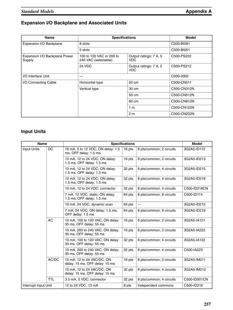
Appendix AStandard Models
257
Expansion I/O Backplane and Associated Units
Name Specifications Model
Expansion I/O Backplane 8 slots C500-BI081
5 slots C500-BI051
Expansion I/O Backplane PowerSupply
100 to 120 VAC or 200 to240 VAC (selectable)
Output ratings: 7 A, 5VDC
C500-PS222
24 VDC Output ratings: 7 A, 5VDC
C500-PS212
I/O Interface Unit --- C500-II002
I/O Connecting Cable Horizontal type 50 cm C500-CN511
Vertical type 30 cm C500-CN312N
50 cm C500-CN512N
80 cm C500-CN812N
1 m C500-CN122N
2 m C500-CN222N
Input Units
Name Specifications Model
Input Units DC 16 mA, 5 to 12 VDC; ON delay: 1.5ms, OFF delay: 1.5 ms
16 pts 8 pts/common; 2 circuits 3G2A5-ID112
10 mA, 12 to 24 VDC; ON delay:1.5 ms, OFF delay: 1.5 ms
16 pts 8 pts/common; 2 circuits 3G2A5-ID213
10 mA, 12 to 24 VDC; ON delay:1.5 ms, OFF delay: 1.5 ms
32 pts 8 pts/common; 4 circuits 3G2A5-ID215
10 mA, 12 to 24 VDC; ON delay:1.5 ms, OFF delay: 1.5 ms
32 pts 8 pts/common; 4 circuits 3G2A5-ID218
10 mA, 12 to 24 VDC; connector 32 pts 8 pts/common; 4 circuits C500-ID218CN
7 mA, 12 VDC; static; ON delay:1.5 ms, OFF delay: 1.5 ms
64 pts 8 pts/common; 8 circuits C500-ID114
10 mA, 24 VDC; dynamic scan 64 pts --- 3G2A5-ID212
7 mA, 24 VDC; ON delay: 1.5 ms,OFF delay: 1.5 ms
64 pts 8 pts/common; 8 circuits 3G2A5-ID219
AC 10 mA, 100 to 120 VAC; ON delay:35 ms, OFF delay: 55 ms
16 pts 8 pts/common; 2 circuits 3G2A5-IA121
10 mA, 200 to 240 VAC; ON delay:35 ms, OFF delay: 55 ms
16 pts 8 pts/common; 2 circuits 3G2A5-IA222
10 mA, 100 to 120 VAC; ON delay:35 ms, OFF delay: 55 ms
32 pts 8 pts/common; 4 circuits 3G2A5-IA122
10 mA, 200 to 240 VAC; ON delay:35 ms, OFF delay: 55 ms
32 pts 8 pts/common; 4 circuits C500-IA223
AC/DC 10 mA, 12 to 24 VAC/DC; ONdelay: 15 ms, OFF delay: 15 ms
16 pts 8 pts/common; 2 circuits 3G2A5-IM211
10 mA, 12 to 24 VAC/DC; ONdelay: 15 ms, OFF delay: 15 ms
32 pts 8 pts/common; 4 circuits 3G2A5-IM212
TTL 3.5 mA, 5 VDC; connector 32 pts 8 pts/common; 4 circuits C500-ID501CN
Interrupt Input Unit 12 to 24 VDC, 13 mA 8 pts Independent commons C500-ID216

Standard Models Appendix A
258
Output Units
Name Specifications Model
Output Units Contact 2 A, 250 VAC/24 VDC; with relaysockets; 8 commons
16 pts 8 pts/common; 2 circuits 3G2A5-OC221
2 A, 250 VAC/24 VDC; with relaysockets; all outputs independent
16 pts Independent commons 3G2A5-OC223
2 A, 250 VAC/24 VDC; with relaysockets
32 pts 8 pts/common; 4 circuits 3G2A5-OC224
Transistor 1 A, 12 to 24 VDC; no output whenexternal power supply is OFF
16 pts 8 pts/common; 2 circuits C500-OD217
2.1 A, 12 to 24 VDC 16 pts 8 pts/common; 2 circuits C500-OD219
1 A, 12 to 48 VDC 16 pts 16 pts/common; 1 circuit 3G2A5-OD411
50 mA, 24 VDC; all outputs inde-pendent
16 pts Independent commons 3G2A5-OD215
0.3 A, 12 to 24 VDC 32 pts 16 pts/common; 2 circuits C500-OD218
0.3 A, 12 to 48 VDC 32 pts 16 pts/common; 2 circuits C500-OD414
0.3 A, 12 to 48 VDC; negativecommon; terminal block
32 pts 32 pts/common; 1 circuit 3G2A5-OD412
0.3 A, 12 to 24 VDC; positive com-mon
32 pts 16 pts/common; 2 circuits 3G2A5-OD212
0.3 A, 12 to 48 VDC; negativecommon; connector
32 pts 16 pts/common; 2 circuits C500-OD415CN
0.1 A, 24 VDC; dynamic scan 64 pts --- 3G2A5-OD211
0.1 A, 24 VDC; static connector 64 pts 8 pts/common; 8 circuits 3G2A5-OD213
Triac 1 A, 100 to 240 VAC 32 pts 8 pts/common; 4 circuits C500-OA225
1.2 A, 100 to 240 VAC 16 pts 8 pts/common; 2 circuits C500-OA226
TTL 35 mA, 5 VDC; connector 32 pts 8 pts/common; 4 circuits C500-OD501CN
DC Input/Transistor OutputUnit
12 to 24-VDC inputs: 10 mA; 12 to24-VDC outputs: 0.3 connector
16 ptseach
--- C500-MD211CN
Dummy I/O Unit Input or output 16, 32,or 64points
--- 3G2A5-DUM01
I/O Power Supply Unit Input: 100 to 120/200 to 240 VAC Output:2A, 24 VDC
--- CV500-IPS01

Appendix AStandard Models
259
Special I/O UnitsName Specifications Model
Analog Input Unit 4 to 20 mA, 1 to 5 V; 2 inputs 2 pts 3G2A5-AD001
0 to 10 V; 2 inputs 2 pts 3G2A5-AD002
0 to 5 V; 2 inputs 2 pts 3G2A5-AD003
–10 to 10 V; 2 inputs 2 pts 3G2A5-AD004
–5 to 5 V; 2 inputs 2 pts 3G2A5-AD005
4 to 20 mA, 1 to 5 V; 4 inputs 4 pts 3G2A5-AD006
0 to 10 V; 4 inputs 4 pts 3G2A5-AD007
0 to 10 V, 0 to 20 mA (selectable); 8 inputs 8 pts C500-AD101
0 to 5 V, 0 to 10 V –5 to 5 V, –10 to 10 V, 0 to 20 mA,–20 to 20 mA; 16 inputs
16 pts C500-AD501
Analog Output Unit 4 to 20 mA, 1 to 5 V; 2 outputs 2 pts 3G2A5-DA001
0 to 10 V; 2 outputs 2 pts 3G2A5-DA002
0 to 5 V; 2 outputs 2 pts 3G2A5-DA003
–10 to 10 V; 2 outputs 2 pts 3G2A5-DA004
–5 to 5 V; 2 outputs 2 pts 3G2A5-DA005
0 to 20 mA, 1 to 5 V/0 to 10 V (selectable); 4 outputs 4 pts C500-DA101
–10 to 10 V, 4 outputs 4 pts C500-DA103
Temperature Sensor Unit Voltage inputs, supports 8 types of thermocouples 8 pts C500-TS501p
Platinum resistance thermometer
p
C500-TS502
High-speed Counter Unit 6-digit BCD; 50 kcps; one counted input; 1 pair of SV 1 pt 3G2A5-CT001
6-digit BCD; 50 kcps; one counted input; 8 pair of SV 1 pt 3G2A5-CT012
50 kcps; 7 operating modes 2 pts C500-CT021
6-digit BCD; 20 kcps; four counted inputs; 6 modes 4 pts C500-CT041
Position Control Unit For stepping motor; one axis 3G2A5-NC111-EV1
For pulse motors; two axes C500-NC222-E
1-axis control C500-NC113
2-axis control C500-NC211
Encoder Adapter 3G2A5-AE001
Teaching Box For 1 axis 3G2A5-TU001-E
For 2 axes C500-TU002-E
Connecting Cable: To connect C500-TU002-E Teach-i B t C500 NC222 E
2 m C200H-CN222ging Box to C500-NC222-E. 4 m C200H-CN422
Connecting Cable: To connect C500-TU002-E Teaching Box to3G2A5-NC103-E/NC111-EV1 Position Control Unit.
C500-CN422
Cam Positioner Unit External outputs: 8 pts; Words output to PC: 2 (16 pts.) C500-CP131
ASCII Unit RAM and EEPROM C500-ASC04
Ladder Program I/O Unit Has 40 instructions (same as a C20P.) Input and output points(16 each.)
C500-LDP01-V1

Standard Models Appendix A
260
Special I/O Units (Continued)
Name Specifications Model
SYSMAC NET Link Unit General-purpose C500-SNT31-V4
SYSMAC LINK Unit Optical C1000H-SLK11
Coaxial C1000H-SLK21-V1
SYSMAC BUS Optical Remote I/O MasterUnit
APF/PCF 3G2A5-RM001-PEV1
Unit
PCF 3G2A5-RM001-EV1
Optical Remote I/O Slave Unit APF/PCF
W/1 optical connector 3G2A5-RT001-PEV1PCF
W/2 optical connectors 3G2A5-RT002-PEV1
PCF W/1 optical connector 3G2A5-RT001-EV1
W/2 optical connectors 3G2A5-RT002-EV1
Wired Remote I/O Master Unit --- C500-RM201
Wired Remote I/O Slave Unit --- C500-RT201
SYSMAC BUSOptical I/O Units
DC Input No-voltage con-tact
8 pts 100-VAC pow-er supply
APF/PCF 3G5A2-ID001-PEOptical I/O Units tact er supply
PCF 3G5A2-ID001-E
AC/DC Input
12 to 24 VAC/DC 8 pts APF/PCF 3G5A2-IM211-PEInput
PCF 3G5A2-IM211-E
AC Input 100 VAC 8 pts APF/PCF 3G5A2-IA121-PE
PCF 3G5A2-IA121-E
ContactOutput
2 A, 250 VAC/24 VDC
8 pts 100/200-VACpower supply
APF/PCF 3G5A2-OC221-PEOutput 24 VDC power supply
PCF 3G5A2-OC221-E
TransistorOutput
0.3 A, 12 to48 VDC
8 pts APF/PCF 3G5A2-OD411-PEOutput 48 VDC
PCF 3G5A2-OD411-E
Voice Unit --- C500-OV001
Associated Units Voice Memory Unit Standard message 12 sec-onds
C500-MP501-H
Specified message 12 sec-onds
C500-MP501-T
32 sec-onds
C500-MP503-T
40 sec-onds
C500-MP504-T
Link Units
Name Specifications Model
Host Link Unit Rack-mounting APF/ PCF C500-LK103-P
PCF C500-LK103
RS-232C/RS-422 C500-LK203
PC Link Unit Maximum of 32 PCs can be linked C500-LK009-V1
Network Link Unit C500-SNT31-V4
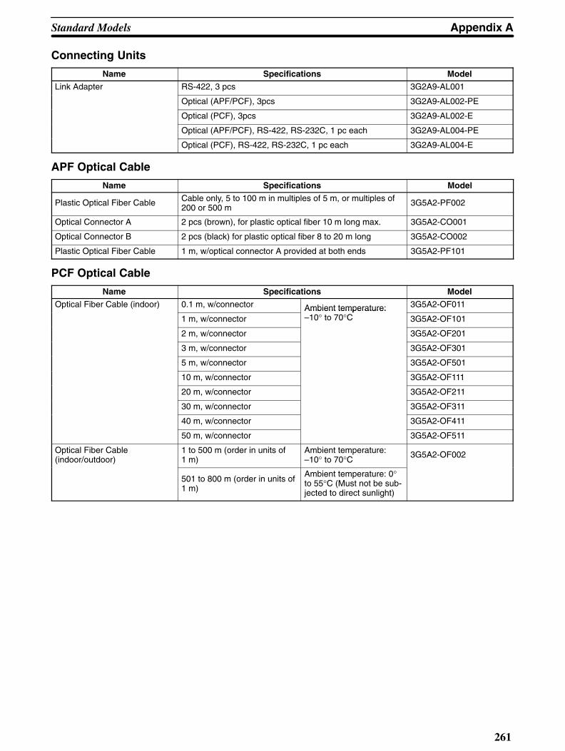
Appendix AStandard Models
261
Connecting Units
Name Specifications Model
Link Adapter RS-422, 3 pcs 3G2A9-AL001
Optical (APF/PCF), 3pcs 3G2A9-AL002-PE
Optical (PCF), 3pcs 3G2A9-AL002-E
Optical (APF/PCF), RS-422, RS-232C, 1 pc each 3G2A9-AL004-PE
Optical (PCF), RS-422, RS-232C, 1 pc each 3G2A9-AL004-E
APF Optical Cable
Name Specifications Model
Plastic Optical Fiber Cable Cable only, 5 to 100 m in multiples of 5 m, or multiples of200 or 500 m
3G5A2-PF002
Optical Connector A 2 pcs (brown), for plastic optical fiber 10 m long max. 3G5A2-CO001
Optical Connector B 2 pcs (black) for plastic optical fiber 8 to 20 m long 3G5A2-CO002
Plastic Optical Fiber Cable 1 m, w/optical connector A provided at both ends 3G5A2-PF101
PCF Optical Cable
Name Specifications ModelOptical Fiber Cable (indoor) 0.1 m, w/connector Ambient temperature: 3G5A2-OF011
1 m, w/connectorAmbient temperature:–10° to 70°C 3G5A2-OF101
2 m, w/connector 3G5A2-OF201
3 m, w/connector 3G5A2-OF301
5 m, w/connector 3G5A2-OF501
10 m, w/connector 3G5A2-OF111
20 m, w/connector 3G5A2-OF211
30 m, w/connector 3G5A2-OF311
40 m, w/connector 3G5A2-OF411
50 m, w/connector 3G5A2-OF511
Optical Fiber Cable(indoor/outdoor)
1 to 500 m (order in units of1 m)
Ambient temperature:–10° to 70°C 3G5A2-OF002
501 to 800 m (order in units of1 m)
Ambient temperature: 0°to 55°C (Must not be sub-jected to direct sunlight)

Standard Models Appendix A
262
Hard-plastic-clad Quartz Fiber Cable: H-PCFUp to 800 m of H-PCF cable can be used between Units in the following systems: SYSMAC NET and SYSMACLINK. In the SYSMAC BUS system, up to 100 m of H-PCF cable can be used between Units whose model numbersuffix contains a P and up to 200 m between other Units whose model number does not contain a P.
You can used connector-equipped cables or assemble cables yourself. The following are required to assembleH-PCF cable: the cable itself, Optical Connectors, Cable Assembly Tool, Cable Cutter Optical Power Tester, HeadUnit, and Master Fiber. The user must assemble and test the optical connectors. Refer to the H-PCF InstallationManual for details.
H-PCF cables can be used at an ambient temperature of between –20° and 70°C.
H-PCF Optical Fiber Cords and CablesCable type Cable color Cable length Model
Two optical conductors withf d
Black 10 meters S3200-HCLB101pfeeder 50 meters S3200-HCLB501
100 meters S3200-HCLB102500 meters S3200-HCLB5021,000 meters S3200-HCLB103
Orange 10 meters S3200-HCLO10150 meters S3200-HCLO501100 meters S3200-HCLO102500 meters S3200-HCLO5021,000 meters S3200-HCLO103
Without feeder Black 10 m S3200-HCCB10150 m S3200-HCCB501100 m S3200-HCCB102500 m S3200-HCCB502
Orange 10 m S3200-HCCO10150 m S3200-HCCO501100 m S3200-HCCO102500 m S3200-HCCO502
Two-core optical cord Black 10 m S3200-HBCB10150 m S3200-HBCB501100 m S3200-HBCB102500 m S3200-HBCB5021,000 m S3200-HBCB103

Appendix AStandard Models
263
H-PCF Optical Fiber Cords and Cables with ConnectorsThe following diagram illustrates the model number for cables with connectors. tension members and power linesare provided in the cable. Half-lock connectors use the S3200-COCF2511 and are compatible with C200H SYS-MAC LINK or SYSMAC NET Link Unit connectors. Full-lock connectors use the S3200-COCF2011 and are com-patible with CV-series SYSMAC LINK or SYSMAC NET and C1000H SYSMAC LINK Link Unit connectors. Full-lock connectors cannot be used with C200H connectors.The above connectors cannot be used with C500 SYSMAC NET Link Unit connectors, cable relays, or NSB. Referto the SYSMAC NET Link System Manual for appropriate connectors for these applications.
S3200-CN--
Cable Length201 2 m501 5 m102 10 m152 15 m202 20 mBlank Over 20 m* *Specify lengths over 20 m separately when ordering.
Connector Type20-20 Full-lock connecter on each end20-25 One full-lock and one half-lock connector25-25 Full lock connector on each end
Optical ConnectorsName Model
SYSMAC NET: CV500-SNT31
SYSMAC LINK: CV500-SLK11, C1000H-SLK11
SYSMAC BUS/2: CV500-RM211/RT211
S3200-COCF2011
SYSMAC NET: C200H-SNT31
SYSMAC LINK: C200H-SLK11
S3200-COCF2511
SYSMAC NET: C500-SNT31-V4S3200-LSU03-01E/NSB11-ES3200-NSUA1-00E/NSUG4-00EFIT10-IF401
S3200-COCH62M
SYSMAC BUS: 3G2A5-RM001-(P)EV13G2A5-RT001/RT002-(P)EV13G2A9-AL-(P)E
S3200-COCH82
SYSMAC NET Relay (M) Connector S3200-COCF62M
SYSMAC NET Relay (F) Connector S3200-COCF62F
Cable Assembly Tool and CutterName Model
Cable Assembly Tool S3200-CAK1062
Optical Power TesterName Model
SYSMAC NET: CV500-SNT31 S3200-CAT2000
SYSMAC LINK: CV500-SLK11
SYSMAC BUS/2: CV500-RM211/RT211
S3200-CAT2700
SYSMAC BUS: 3G2A5-RM001-(P)EV13G2A5-RT001/RT002-(P)EV1
S3200-CAT2820
SYSMAC NET: S3200-LSU03-01EFIT10-IF401
S3200-CAT3200
Note Each Optical Power Tester is provided with a replaceable Head Unit. There is no difference in type among allOptical Power Testers except for the head unit. This means the S3200-CAT2000 Optical Power Tester, forexample, can be used as the S3200-CAT2700, S3200-CAT2820, or S3200-CAT3200 Optical Power Testerby just replacing the Head Unit of the S3200-CAT2000 with those for the S3200-CAT2700,S3200-CAT2820, or S3200-CAT3200.

Standard Models Appendix A
264
Peripheral Devices
Name Specifications Model
Programming Console Vertical type, w/backlight C500F-PRO19
Programming Console Adapter
Optional extension cable is necessary. C500-AP001
Programming Console BaseUnit
C500-BP001
Programming Console Handheld type C500F-PRO29
Programming Console Adapter
Necessary for Handheld Programming Console C500-AP003
Connecting Cable Necessary for Handheld Pro-gramming Console
Cable length: 2 m C200H-CN222gramming Console
Cable length: 4 m C200H-CN422
Programming Console Connecting Cable
For extension and connectionof FIT
Cable length: 2 m 3G2A2-CN221Connecting Cable of FIT
Cable length: 5 m C500-CN523
Cable length: 10 m C500-CN131
Cable length: 20 m C500-CN231
Cable length: 30 m C500-CN331
Cable length: 40 m C500-CN431
Cable length: 50 m C500-CN531
Cassette Recorder Connect-ing Cable
Cable length: 1 m SCYP0R-PLG01
Flowchart Support Software 3.5-inch, 2HD (to be released soon) C1000HF-SU410
5-inch 2HD (to be released soon) C1000HF-SU610
8-inch 2D (to be released soon) C1000HF-SU810
Optional Products
Name Specifications Model
Battery --- 3G2A5-BAT08
I/O Terminal Cover For 38-pin block, special type 3G2A5-COV11
For 38-pin block, standard C500-COV12
For 20-pin block, standard C500-COV13
Connector Cover (see note) Protector for I/O bus connector 3G2A5-COV01
Space Unit For I/O Unit 3G2A5-SP002
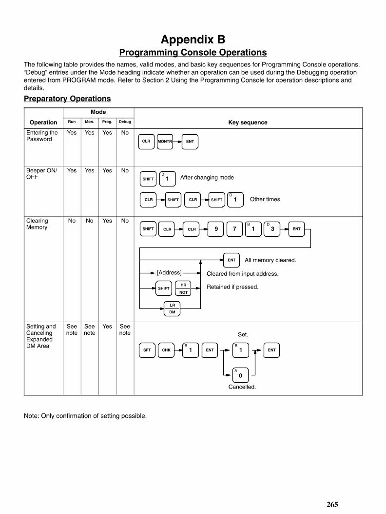
Note: Only confirmation of setting possible.
265
Appendix BProgramming Console Operations
The following table provides the names, valid modes, and basic key sequences for Programming Console operations.“Debug” entries under the Mode heading indicate whether an operation can be used during the Debugging operationentered from PROGRAM mode. Refer to Section 2 Using the Programming Console for operation descriptions anddetails.
Preparatory Operations
Mode
Operation Run Mon. Prog. Debug Key sequence
Entering thePassword
Yes Yes Yes NoCLR MONTR ENT
Beeper ON/OFF
Yes Yes Yes NoSHIFT
B1 After changing mode
CLR SHIFT CLR SHIFTB
1 Other times
ClearingMemory
No No Yes NoCLRSHIFT CLR 9 7
B1
D3 ENT
ENT
HR
NOTSHIFT
LR
DM
[Address]
All memory cleared.
Cleared from input address.
Retained if pressed.
Setting andCancelingExpandedDM Area
Seenote
Seenote
Yes Seenote
CHKB
1SFT ENT
A
0
B1ENT
Set.
Cancelled.

Programming Console Operations Appendix B
266
Mode
Operation Key sequenceDebugProg.Mon.Run
Registeringthe I/O Table
No No Yes No
SFT CHK ENT ENT
9 7B
1D
3 ENTChannel multipliers registerednext, if necessary.
Verifying theI/O Table
Yes Yes Yes Yes
SHIFT CHK ENTC
2 ENT ENT
Reading theI/O Table
Yes Yes Yes Yes
SFT CHK ENTB
1 ENT
ENT
SFT ENT
[0—7] [0—7]
Rackno.
Slotno.
+ / –
Changingthe I/O Table
No No Yes No
CHGA
0 ENT
D3
B1
I/O Table Readin progress. O: Output Unit
1: Input Unit
3: Channel
Transferringthe I/O Table
No No Yes No
SFT CHK ENTD
3 ENT 9
9
7
7
B1
B1
C2
D3
ENT
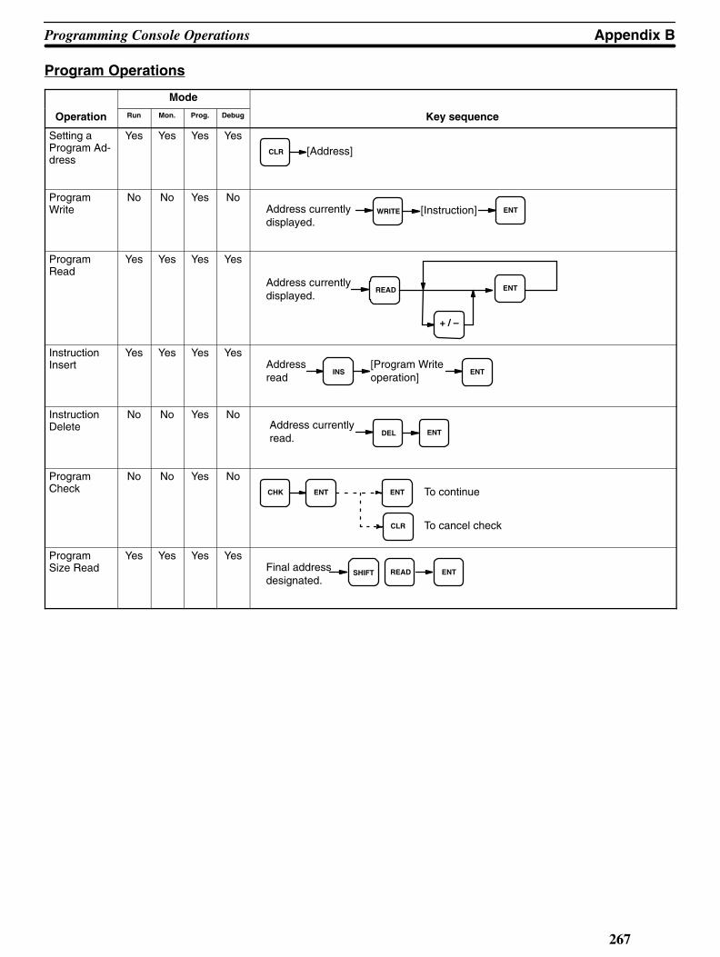
Appendix BProgramming Console Operations
267
Program Operations
Mode
Operation Run Mon. Prog. Debug Key sequence
Setting aProgram Ad-dress
Yes Yes Yes YesCLR [Address]
ProgramWrite
No No Yes NoENTWRITEAddress currently
displayed.[Instruction]
ProgramRead
Yes Yes Yes Yes
READ ENTAddress currentlydisplayed.
+ / –
InstructionInsert
Yes Yes Yes Yes
ENTINSAddressread
[Program Writeoperation]
InstructionDelete
No No Yes No
DEL ENTAddress currentlyread.
ProgramCheck
No No Yes NoCHK ENT ENT
CLR
To continue
To cancel check
ProgramSize Read
Yes Yes Yes Yes
SHIFT READ ENTFinal addressdesignated.

Programming Console Operations Appendix B
268
Debugging Operations
Mode
Operation Run Mon. Prog. Debug Key sequence
Entering theDebug Oper-ation
No No Yes Yes
SHIFT CHKA
0 ENT
B1
SHIFT CHK ENT
Entering Debug Operation
No group jumps
Jumps as written
Leaving Debug Operation
Step Execu-tion
No No Yes Yes
SHIFT SET ENT ENT ENT[Start address]
Step execution
Forced Con-dition Execu-tion
No No No Yes
SET
RESET
ENT[Step Execution]
Section Execution
No No No Yes
SHIFT SET ENT
ENT SHIFT ENT
[Startingaddress]
Stoppingaddress]
[

Appendix BProgramming Console Operations
269
Mode
Operation Key sequenceDebugProg.Mon.Run
Step Trace No No Yes Yes
MONTR LBL CHG ENT
+ / – ENT
[Trigger addressor label]
[Delay]
[Label no.]
ReadingTraceMemory
No Yes Yes Yes
MONTR FUNC
2 ENT
+ / –[Step Trace]
Monitoring and Data Change Operations
Mode
Operation Run Mon. Prog. Debug Key sequence
AddressMonitoring
Yes Yes No No
READ ENTAddress currentlydisplayed.
+ / –
ExecutionAddressMonitor
Yes Yes Yes Yes
SHIFT MONTR
SHIFT ENT
ENT HR
NOT
Designated addressdisplayed.
Currently executedaddress displayed.

Programming Console Operations Appendix B
270
Mode
Operation Key sequenceDebugProg.Mon.Run
Data AreaMonitor
Yes Yes Yes Yes
MONTR ENT
+ / –
ENT
[Bit no.]
[Bit in-struction]
[*/CH and data areakey if required.]
TIM or CNT
[Channel no.]
[Timer/counter no.]
Force Set/Reset
No Yes Yes Yes
SET
RESET
ENT[Data AreaMonitor]
ChannelDataChanges
No Yes Yes Yes
CHK ENT[Data Area Monitor] [New value ]
Binary Monitor
Yes Yes Yes Yes
SHIFT ENTEXT
+ / –
[Data AreaMonitor]
BinaryChange
No Yes Yes YesA
0
B1
ENT[BinaryMonitor CHG
Three-Chan-nel Monitor
Yes Yes Yes Yes
EXT + / – ENT
SFT ENT
[Data AreaMonitor]
(Group programmonitoring)

Appendix BProgramming Console Operations
271
Mode
Operation Key sequenceDebugProg.Mon.Run
Three-Chan-nel Change
No Yes Yes Yes
ENT[Three-ChannelMonitor] CHG New value
S Numberand Mes-sage Displays
No Yes Yes YesENTDEL
Address currentlyread.
File Memory Cassette Operations
Mode
Operation Run Mon. Prog. Debug Key sequence
File MemoryClear
No Yes Yes YesCLR SHIFT EXT ENT
B1 ENT 9 7
B1
D3
ENT ENT
ENT
[Startingblock]
[Endingblock]
File MemoryWrite
No Yes Yes Yes[Endingaddress]
CLR SHIFT EXTB
1 ENTB
1 ENT
SHIFT
SHIFT
SHIFT
TIM
CNT
CNR
HR
NOT
LR
DM
LR
DMENT ENT ENT
ENT*CH
ENT ENT ENT ENT ENT
[Starting DMchannel]
[No. ofblocks]
[Startingblock]
[Startingchannel]
[Startingaddress]
[Startingblock]

Programming Console Operations Appendix B
272
Mode
Operation Key sequenceDebugProg.Mon.Run
File MemoryVerify
No Yes Yes Yes
[Startingblock]
CLR SHIFT EXTB
1 ENTB
1 ENT
SHIFT
SHIFT
SHIFT
TIM
CNT
CNR
HR
NOT
LR
DM
LR
DMENT ENT ENT
ENT*CH
ENT ENT ENT ENT
ENTC
2
C2
[Starting DMchannel]
[No. ofblocks]
[Startingchannel]
[Startingaddress]
[Startingblock]
File MemoryRead
No No Yes No
CLR SHIFT EXTB
1 ENTB
1 ENT
SHIFT
SHIFT
SHIFT
TIM
CNT
CNR
HR
NOT
LR
DM
LR
DMENT ENT ENT
ENT*CH
ENT ENT ENT ENT
ENT
B1
B1
[Starting DMchannel]
[No. ofblocks]
[Startingblock]
[Startingchannel]
[Startingaddress]
[Startingblock]

Appendix BProgramming Console Operations
273
Mode
Operation Key sequenceDebugProg.Mon.Run
File MemoryRead/Write
Yes Yes Yes YesCLR SHIFT EXT
C2 ENT
ENT
+ / –
WRITE ENT
[Startingblock]
[Channel] [New data]
File MemoryIndex Read
Yes Yes Yes Yes Blocknumber]
CLR SHIFT EXTC
2 ENT
SHIFT READ ENT
+ / –
[Blocknumber]
[
Saving aProgram toTape
No No Yes No
[Startingaddress]
CLR EXT ENT ENT ENT[Filenumber]
ENT
ENT
[Stoppingaddress]
[Start recorder]
Within 5 s
RestoringProgramData
No No Yes No
CLR EXT ENTB
1 ENT ENT
ENT
[Filenumber]
[Startingaddress] [Start recorder]
Within 5 s

Programming Console Operations Appendix B
274
Mode
Operation Key sequenceDebugProg.Mon.Run
VerifyingProgramData
No No Yes No
CLR EXT ENT ENT ENT
ENT
C2
[Filenumber]
[Startingaddress] [Start recorder]
Within 5 s
DM<–> Cas-sette Tape:Save, Re-store, andVerify
No No Yes No
CLRB
1
C2
ENT
ENT
EXT
[Saving]
[Restor-ing]
[Verify-ing]
[File num-ber]
[Start recorder]
Within 5 s

275
Appendix CProgramming Instructions
This appendix offers only a short description of the function of each instruction, along with the flowchart sym-bol and data areas used for each. Be sure you understand the limits and requirements of any instruction be-fore you use it. Refer to Section 4 Programming Instructions for details. Both flowchart (in normal parentheseslike these) and ladder diagram <in pointed parentheses like these> function codes have been provided whereavailable. Programming Console keys are available for those instructions that do not have function codes.
Programming Instructions: Basic Instructions
Instruction Mnemonic Symbol Function Operands
Load LD
LD B
Used to start instruction block with sta-tus of designated bit.
B:IRSRHRAR
Load Inverse LD NOT
LD NOT B
Used to start instruction block with in-verse of designated bit.
ARLRTC
AND AND
AND B
Logically ANDs status of designated bitwith execution condition.
AND IN-VERSE
AND NOT
AND NOT B
Logically ANDs inverse of designatedbit with execution condition.
OR OR
OR B
Logically ORs status of designated bitwith execution condition.
OR INVERSE OR NOT
OR NOT B
Logically ORs inverse of designated bitwith execution condition.
Block AND AND LD
AND LD
Logically ANDs result of precedingblocks
None
Block OR OR LD
OR LD
Logically ORs result of preceding blocks

Programming Instructions Appendix C
276
IR SR HR AR LR TC DM #
00000 TO 24615000 TO 246
24700 TO 25515247 TO 255
HR 0000 TO HR 9915HR 00 TO HR 99
AR 0000 TO AR 2715AR 00 TO AR 27
LR 0000 TO LR 6315LR 00 TO LR 63
TC 000 TO TC 511 Normal: DM 0000TO DM 4095Expanded: DM 0000TO DM 9999
0000 to 9999
Instruction OperandsFunctionSymbolMnemonic
Output OUT
OUT B
Turns ON designated bit. B:IRSRHRAR
OutputInverse
OUT NOT
OUT NOT B
Turns OFF designated bit.ARLR
ConditionalOutput
OUTC(00)
OUTC B
If execution condition is ON, designatedbit is turned ON; if OFF, bit is turnedOFF.
Inverse ConditionalOutput
OUTC(00)NOT
OUTC NOT B
If execution condition is ON, designatedbit is turned OFF; if OFF, bit is turnedON.
Interlock IL(38)<02>
IL(38)
B
Designates beginning of interlockedprogram. If interlock bit (B) is OFF, alloutputs turned OFF and all timer PV re-set between IL(38) and ILC(39). Otherinstructions treated as NOP; counter PVmaintained.
B:IRSRHRARLR
Interlock Clear ILC(39)<03>
ILC(39)
Designates end of interlocked program.If interlock bit is OFF, all outputs turnedOFF and all timer PV reset betweenIL(38) and ILC(39). Other instructionstreated as NOP; counter PV main-tained.
None
DifferentiationUp
DIFU(40)<13>
DIFU(40) N
B
Establishes ON condition for one ex-ecution after it detects OFF to ON tran-sition in designated bit (B). OtherwiseOFF condition is maintained. Used be-fore WAIT, CJP, SKIP(46), OUTC(00).
B:IRSR HRARLR
DifferentiationDown
DIFD(41)<14>
DIFU(41) N
B
Establishes ON condition for one ex-ecution after it detects ON to OFF tran-sition in designated bit (B). OtherwiseOFF condition is maintained. Used be-fore WAIT, CJP, SKIP(46), OUTC(00).
No Operation NOP
NOP
Nothing is executed and next instructionis moved to.
None

Appendix CProgramming Instructions
277
Programming Instructions: Flow Control
Instruction Mnemonic Symbol Function Operands
Wait WAIT
WAIT
Pauses program execution until execu-tion condition for it goes ON. Used fol-lowing LD, AND, OR, AND LD, OR LD,DIFU(40), DIFD(41), TIM, CNT,CNTR<12>, ANDG(01), ORG(02), orSBT(34).
None
Inverse Wait WAIT NOT
WAIT NOT
Pauses execution until execution condi-tion for it goes OFF. Used following LD,AND, OR, AND LD, OR LD, DIFU(40),DIFD(41), TIM, CNT, CNTR<12>,ANDG(01), ORG(02), or SBT(34).
Label LBL
LBL N
Used to designate destination for jumpsindicated by JMP, CJP, RPT(37), orBRZ(59).
N:000 through999
Jump JMP
JMP L
Used to unconditionally move programexecution to designated label.
L:IRSRHRARLRTCDM
ConditionalJump
CJP
CJP
Moves program execution to designatedlabel number if preceding condition isON, and to instruction immediately fol-lowing CJP if preceding condition isOFF.
L:IRSRHRARLR
Inverse ConditionalJump
CJP NOT
CJP NOT
Moves program execution to designatedlabel number if preceding condition isOFF, and to instruction immediately fol-lowing CJP if preceding condition is ON.
LRTCDM
Repeat RPT(37)
RPT(37) L
R
Used to return to LBL (L) and repeat in-structions between LBL and RPT(37)specified number of times (R) beforeproceeding to instruction following RPT.
L/R:IRSRHRARLRTCDM
ConditionalSkip
SKIP(46)
Yes
No
SKIP(46) N
Moves program execution to instructionimmediately after designated number ofinstructions if preceding condition isON, and to instruction immediately fol-lowing SKIP(46) if preceding conditionis OFF.
N:1 through 9
Inverse ConditionalSkip
SKIP(46) NOT
Yes
No
SKIP(46) NOT N
Moves program execution to instructionimmediately after designated number ofinstructions if preceding condition isOFF, and to instruction immediately fol-lowing SKIP(46) if preceding conditionis ON.
N:1 through 9

Programming Instructions Appendix C
278
IR SR HR AR LR TC DM #
00000 TO 24615000 TO 246
24700 TO 25515247 TO 255
HR 0000 TO HR 9915HR 00 TO HR 99
AR 0000 TO AR 2715AR 00 TO AR 27
LR 0000 TO LR 6315LR 00 TO LR 63
TC 000 TO TC 511 Normal: DM 0000TO DM 4095Expanded: DM 0000TO DM 9999
0000 to 9999
Instruction OperandsFunctionSymbolMnemonic
Branch forZero
BRZ(59)
BRZ(59) L
C
Moves program execution to designatedlabel (L) if operand channel (C) is allzeros, and to instruction immediatelyfollowing BRZ(59) if channel containsanything else.
L/C:IRSRHRARLRTC
InverseBranch forZero
BRZ(59) NOT
BRZ(59) NOT L
C
Moves program execution to instructionimmediately following BRZ(59) if oper-and channel (C) is all zeros; to desig-nated label (L) if channel contains any-thing else.
TCDM

Appendix CProgramming Instructions
279
Programming Instructions: Timers and Counters
Instruction Mnemonic Symbol Function Operands
Timer TIM
TIM N
SV
TIM 000 through TIM 383 measure indecrements of 0.1 second from SV be-tween 0 and 999.9; TIM 384 throughTIM 511, in decrements of 0.01 secondfrom SV between 0 and 99.99 seconds.Used before WAIT, CJP, SKIP(46), orOUTC(00).
N: 000—511SV:IRHRARLRDM#
Timer Start TMS(30)
TMS(30) N
SV
Used to define and start timer by desig-nating timer number (N) and SV.
#CP:IRSRHRARLR
Counter CNT
CNT N
SV
CP
A preset decrementing counter. Decre-ments PV when count input pulse goesfrom OFF to ON. Used before WAIT,CJP, SKIP(46), or OUTC(00).
LRC:IRHRARLRDM
ReversibleCounter
CNTR <12>
CNTR(12) N
SV
C
Increases or decreases PV by onewhenever increment or decrement inputsignal goes from OFF to ON. Incrementsignal is bit 15 of control channel (C).Decrement signal is bit 14. Used beforeWAIT, CJP, SKIP(46), or OUTC(00).
Timer/CounterReset
CNR
CNR N
St
E
Used to reset timers and counters totheir SV or to reset other channels tozero. To reset one timer or counter, in-put TC number (N) as part of instructionline. To reset multiple timers/counters orother channels, input starting (St) andend (E) channels.
N: 000—511St/E:IRHRARLRTCDM*DM
Multi-outputTimer
MTIM(80)
MTIM(80)
R
PVC
FSV
An incrementing timer instruction witheight set values to turn ON eight corre-sponding output bits in result channel(R). Bit 08 of result channel is reset in-put; bit 09, timer pause input. Channelcontaining first SV: FSV; Channel towhich PV is output: PVC
FSV/PVC/R:IRHRARLRDM*DM

Programming Instructions Appendix C
280
IR SR HR AR LR TC DM #
00000 TO 24615000 TO 246
24700 TO 25515247 TO 255
HR 0000 TO HR 9915HR 00 TO HR 99
AR 0000 TO AR 2715AR 00 TO AR 27
LR 0000 TO LR 6315LR 00 TO LR 63
TC 000 TO TC 511 Normal: DM 0000TO DM 4095Expanded: DM 0000TO DM 9999
0000 to 9999
Programming Instructions: Data Shifting
Instruction Mnemonic Symbol Function Operands
Shift Register SFT
SFT
S
B
E
Shifts status of designated bit (S) intoshift register defined between beginning(B) and end (E) channel, and shifts allbits in register by one.
E B15 150 0
IN
B/E/S:IRSRHRARLR
ReversibleShift Register
SFTR<84>
C
B
E
SFTR(84)
Shifts data in specified channel or se-ries of channels to either left or right.Beginning (B) and end channel (E)must be specified. Control channel (C)contains shift direction, reset input, anddata input.
E B
CY
E B
15 D2 0 15 D1
IN 15 D2 0 15 D1
CY
B/E/C:IRHRARLRDM*DM
Arithmetic ShiftLeft
ASL(63)<25>
ASL(63)
Ch
Shifts each bit in single channel (Ch) ofdata one bit to left, with CY.
Ch15 00
CY
Ch:IRHRARLRDM*DMArithmetic Shift
RightASR(62)<26>
ASR(62)
Ch
Shifts each bit in single channel (Ch) ofdata one bit to right, with CY.
0 Ch CY
15 00
*DM
Rotate Left ROL(70)<27>
ROL(70)
Ch
Rotates bits in single channel (Ch) ofdata one bit to left, with carry (CY).
15 00
CYCh
Rotate Right ROR(69)<28>
ROR(69)
Ch
Rotates bits in single channel (Ch) ofdata one bit to right, with carry (CY).
15 00
CY Ch

Appendix CProgramming Instructions
281
Instruction OperandsFunctionSymbolMnemonic
One Digit ShiftLeft
SLD(75)<74>
SLD(75) St
B
E
Left shifts data between starting (St)and end (E) channels by one digit (fourbits).
E
B
B+ 1
St/E IR HR AR LR DM *DM
One Digit ShiftRight
SRD(76)<75>
SRD(76)
St
E
0 E
Right shifts data between starting (St)and end (E) channels by one digit (fourbits)
B
B+ 1
Word Shift WSFT(94)<16>
WSFT(94)
Ch
St
E
Left shifts data between starting (St)and end (E) channels in channel units,writing content of specified channel (Ch)into starting channel.
St/E:IRHRARLRDMDM
Ch:IRSRHRARLRTCDM*DM

Programming Instructions Appendix C
282
IR SR HR AR LR TC DM #
00000 TO 24615000 TO 246
24700 TO 25515247 TO 255
HR 0000 TO HR 9915HR 00 TO HR 99
AR 0000 TO AR 2715AR 00 TO AR 27
LR 0000 TO LR 6315LR 00 TO LR 63
TC 000 TO TC 511 Normal: DM 0000TO DM 4095Expanded: DM 0000TO DM 9999
0000 to 9999
Programming Instructions: Data Movement
Instruction Mnemonic Symbol Function Operands
Move MOV(50)<21>
MOV(50)
S
D
Transfers source data (S) (channel orfour-digit constant) to destination chan-nel (D).
S:IRSRHRARLRTCDM*DM
Move Not MVN(51)<22>
MVN(51)
S
D
Inverts source data (S) (channel or four-digit constant) and then transfers it todestination channel(D).
*DM#D:IRHRARLRDM*DM
Block Set BSET(73)<71>
BSET(73)
Ch
St
E
Copies content of one channel or con-stant (Ch) to several consecutive chan-nels (starting channel (St) through endchannel (E)). Used to change timer/counter data.
S B
E
St/E:IRSRHRARLRTCDM*DM#
Ch:IRHRARLRTCDM*DM
Block Transfer XFER(72)<70>
XFER(72)
N
S
D
Moves content of several consecutivesource channels (S: beginning sourcechannel) to consecutive destinationchannels (D: beginning destinationchannel). N: number of channels
S
S + 1
D
D + 1
S + n D + n
No. ofWords
N:IRHRARLRTCDM*DM#
S :IRHRARLRTCDM*DMD:IRSRHRARLRTCDM*DM#

Appendix CProgramming Instructions
283
Instruction OperandsFunctionSymbolMnemonic
Move Bit MOVB<82>
MOVB(82)
S
C
D
Transfers designated bit of designatedsource channel or constant (S) to des-ignated bit of designated destinationchannel (D). Source and destinationbits specified in control data (C).
S
D
S:IRSRHRARLRDM*DM#
C:IRHRARLRTCDM*DM#D:IRHRARLRDM*DM
Move Digit MOVD<83>
MOVD(83)
S
C
D
Moves hexadecimal content of speci-fied four-bit source digit (S: sourcechannel) to specified destination digit(s)(D: destination channel) for up to fourdigits at once. Source and destinationdigits specified in control data (C).
S
D
15 0
S:IRSRHRARLRTCDM*DM#
C:IRHRARLRTCDM*DM#D:IRHRARLRTCDM*DM
Data Exchange
XCHG(74)<73>
XCHG(74)
D1
D2
Exchanges contents of two differentchannels (E1 and E2).
E1 E2
D1/D2:IRHRARLRTCDM*DM

Programming Instructions Appendix C
284
IR SR HR AR LR TC DM #
00000 TO 24615000 TO 246
24700 TO 25515247 TO 255
HR 0000 TO HR 9915HR 00 TO HR 99
AR 0000 TO AR 2715AR 00 TO AR 27
LR 0000 TO LR 6315LR 00 TO LR 63
TC 000 TO TC 511 Normal: DM 0000TO DM 4095Expanded: DM 0000TO DM 9999
0000 to 9999
Instruction OperandsFunctionSymbolMnemonic
Single Channel Distribution
DIST<80>
DIST(80)
S
DBs
Of
Moves one channel of source data (S)to pl destination channel whose ad-dress is given by destination basechannel (DBs) plus offset (Of).
SBase(DBs)
+Offset (OF)
( S ) ( DBs + Of )
S:IRSRHRARLRTCDM*DM#
DBs:IRHRARLRTCDM*DM Of:RHRARLRTCDM*DM#
Data Collection
COLL<81>
COLL(81)
SBs
Of
D
Extracts data from source channel andwrites it to destination channel (D).Source channel is determined by add-ing offset (Of) to source base channel(SBs).
Base(DBs)+
Offset (OF)
( SBs+Of ) ( D )
SBs:IRSRHRARLRTCDM*DM
Of:IRHRARLRTCDM*DM# D:IRHRARLRTCDM*DM
Programming Instructions: Data Comparison
Instruction Mnemonic Symbol Function Operands
Compare CMP(52)<20>
CMP(52)
C1
C2
Compares two sets of four-digit hexade-cimal data (C1 and C2) and outputs re-sult to GR, EQ, and LE.
C1/C2:IRSRHRARLRTCDM
Compare Long CMPL<60>
CMPL(60)
C1
C2
Compares two sets of eight-digit hexa-decimal data (C1 and C2: rightmostchannels) and outputs result to GR, EQ,and LE flags in SR area.
DM*DM#

Appendix CProgramming Instructions
285
Instruction OperandsFunctionSymbolMnemonic
Block Compare
BCMP<68>
BCMP(68)
CD
CB
R
Compares 1-channel binary value (CD)with 16 ranges in comparison table(CB: First channel of comparison table).If value falls within any ranges, corre-sponding bits of result channel (R) set.
CD
CR CB+1CB+2 CB+3
CB+4 CB+5
CB+30 CB+31
101
0
Lower limit Upper limit
Lower limit S Upper limit 1
CD:IRSRHRARLRTCDM*DM#
CB:IRSRHRLRTCDM*DMR:IRHRARLRTCDM*DM
Table Compare
TCMP<85>
TCMP(85)
CD
TB
R
Compares four-digit hexadecimal value(CD) with values in table consisting of16 channels (TB: First channel of com-parison table). If value equals any val-ue, corresponding bit of result channel(R) set.
CD CB
CB+ 1
CB+ 13CB+ 14CB+ 15
1:agreement0:disagreement
010
101
CD:IRSRHRARLRTCDM*DM#
TB:IRSRHRARLRTCDM*DM R:IRHRARLRTCDM*DM

Programming Instructions Appendix C
286
IR SR HR AR LR TC DM #
00000 TO 24615000 TO 246
24700 TO 25515247 TO 255
HR 0000 TO HR 9915HR 00 TO HR 99
AR 0000 TO AR 2715AR 00 TO AR 27
LR 0000 TO LR 6315LR 00 TO LR 63
TC 000 TO TC 511 Normal: DM 0000TO DM 4095Expanded: DM 0000TO DM 9999
0000 to 9999
Programming Instructions: Data Conversion
Instruction Mnemonic Symbol Function Operands
BCD to Binary BIN(57)<23>
BIN(57)
S
R
Converts four-digit, BCD data in sourcechannel (S) into 16-bit binary data, andoutputs converted data to result chan-nel (R).
x100
x101
x102
x103
x160
x161
x162
x163
S R (BCD) (BIN)
S:IRSRHRARLRTCDM*DM
R:IRHRARLRDM*DM
BCD to Double Binary
BINL<58>
BINL(58)
S
R
Converts BCD value in two sourcechannels (S: beginning source channel)into binary and outputs converted datato two result channels (R: beginningchannel).
S
S + 1
R
R + 1
S:IRSRHRARLRTCDM*DM
R:IRHRARLRDM*DM
Binary to BCD BCD(58)<24>
BCD(58)
S
R
Converts binary data in source channel(S) into BCD, and outputs converteddata to result channel (R).
S:IRSRHRARLRDM*DM
R:IRHRARLRDM*DM
Double Binaryto Double BCD
BCDL<59>
BCDL(59)
S
R
Converts binary value in two sourcechannels (S: beginning channel) intoeight digits of BCD data, and outputsconverted data to two result channels(R: beginning channel).
S
S + 1
R
R + 1
S:IRSRHRARLRTCDM*DM
R:IRHRARLRDM*DM

Appendix CProgramming Instructions
287
Instruction OperandsFunctionSymbolMnemonic
4 to 16 Decoder
MLPX(77)<76>
MLPX(77)
S
Di
RB
Converts up to four hexadecimal digitsin source channel (S) into decimal val-ues from 0 to 15 and turns ON, in resultchannel(s) (R), bit(s) corresponding toconverted value. Digits designated in Dichannel.
S 3 2 1 0
3
0 to F
Di
S:IRSRHRARLRTCDM*DM
Di:IRHRARLRTCDM*DMRB:IRHRARLRDM*DM #
Encoder DMPX(78)<77>
DMPX(78)
SB
R
Di
Determines position of highest ON bit inspecified beginning source channel(SB) and turns ON corresponding bit(s)in result channel (R). First digit desig-nated with Di
.
S
15 0
3 0
R 3 2 1 0 0 to F
SB:IRSRHRARLRTCDM*DM
R:IRHRARLR DM*DMDi:IRHRARLRTCDM*DM#
Seven-Segment Decoder
SDEC(79)<78>
SDEC(79)
S
Di
DB
Converts hexadecimal values fromsource channel (S) to data for seven-segment display. Result to consecutivehalf channels starting at beginning des-tination channel (DB). Di designatesdigit and destination details.
.S 3 2 1 0
Di 0 to F
S:IRSRHRARLRTCDM*DM
Di:IRHRARLRTCDM*DM# DB:IRHRARLRDM*DM

Programming Instructions Appendix C
288
IR SR HR AR LR TC DM #
00000 TO 24615000 TO 246
24700 TO 25515247 TO 255
HR 0000 TO HR 9915HR 00 TO HR 99
AR 0000 TO AR 2715AR 00 TO AR 27
LR 0000 TO LR 6315LR 00 TO LR 63
TC 000 TO TC 511 Normal: DM 0000TO DM 4095Expanded: DM 0000TO DM 9999
0000 to 9999
Instruction OperandsFunctionSymbolMnemonic
ASCII CodeConversion
ASC<86>
ASC(86)
S
Di
DB
Converts hexadecimal values fromsource channel (S) to eight-bit ASCIIcode beginning at leftmost or rightmosthalf of beginning destination channel(DB). Di designates digit and destina-tion details.
S 3 2 1 0
Di8-bit
data
0 to F
S:IRSRHRARLRTCDM*DM
Di:IRHRARLRTCDM*DM# DB:IRHRARLRDM*DM
Bit Counter BCNT<67>
BCNT(67)
N
St
R
Counts number of ON bits in one ormore channels (St:: starting channel)and outputs result to specified channel(R). N: number of channels to becounted
N:IRSRHRARLRTCDM*DM
St:IRSRHRARLRTCDM*DMD:IRHRARLRTCDM*DM#
Programming Instructions: BCD Calculations
Instruction Mnemonic Symbol Function Operands
Increment INC(60)<38>
INC(60)
Ch
Increments four-digit BCD channel (Ch)by one, without affecting carry (CY).
Ch:IRHRARLRDM*DMDecrement DEC(61)<39>
DEC(61)
Ch
Decrements four-digit BCD channel by1, without affecting carry (CY).
*DM
Set Carry STC(95)<40>
STC(95)
Sets carry flag (i.e.,turns CY ON). None
Clear Carry CLC(96)<41>
CLC(96)
CLC(96) clears carry flag (i.e, turns CYOFF).
None
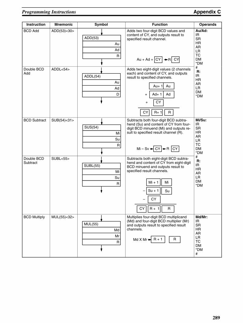
Appendix CProgramming Instructions
289
Instruction OperandsFunctionSymbolMnemonic
BCD Add ADD(53)<30>
ADD(53)
Au
Ad
R
Adds two four-digit BCD values andcontent of CY, and outputs result tospecified result channel.
CY CYAu + Ad + R
Au/Ad:IRSRHRARLRTCDM*DM#Double BCD
AddADDL<54>
ADDL(54)
Au
Ad
D
CY R+ 1 R
Adds two eight-digit values (2 channelseach) and content of CY, and outputsresult to specified channels.
Au+ 1 Au
+ Ad+ 1 Ad
+ CY
# R:IRHRARLRDM*DM
BCD Subtract SUB(54)<31>
SUS(54)
Mi
Su
R
Subtracts both four-digit BCD subtra-hend (Su) and content of CY from four-digit BCD minuend (Mi) and outputs re-sult to specified result channel (R).
Mi – Sv RCY CY
Mi/Su:IRSRHRARLRTCDM*DM#Double BCD
SubtractSUBL<55>
SUBL(55)
Mi
Su
R
Subtracts both eight-digit BCD subtra-hend and content of CY from eight-digitBCD minuend and outputs result tospecified result channels.
Mi + 1 Mi
– Su + 1 Su
– CY
CY R + 1 R
# R:IRHRARLRDM*DM
BCD Multiply MUL(55)<32>
MUL(55)
Md
Mr
R
Multiplies four-digit BCD multiplicand(Md) and four-digit BCD multiplier (Mr)and outputs result to specified resultchannels.
Md X Mr R + 1 R
Md/Mr:IRSRHRARLRTCDM*DM#

Programming Instructions Appendix C
290
IR SR HR AR LR TC DM #
00000 TO 24615000 TO 246
24700 TO 25515247 TO 255
HR 0000 TO HR 9915HR 00 TO HR 99
AR 0000 TO AR 2715AR 00 TO AR 27
LR 0000 TO LR 6315LR 00 TO LR 63
TC 000 TO TC 511 Normal: DM 0000TO DM 4095Expanded: DM 0000TO DM 9999
0000 to 9999
Instruction OperandsFunctionSymbolMnemonic
Double BCDMultiply
MULL<56>
MULL(56)
Md
Mr
R
Multiplies eight-digit BCD multiplicandand eight-digit BCD multiplier and out-puts result to specified result channels.
Md+ 1 Md
Mr+ 1 Md
R + 3 R + 2 R + 1 R
X
R:IRHRARLRDM*DM
BCD Divide DIV(56)<33>
DIV(56)
Dd
Dr
R
Divides four-digit BCD dividend (Dd) byfour-digit BCD divisor (Dr) and outputsresult to specified result channels. Rreceives quotient; R + 1 receives re-mainder.
R + 1 RDd ÷ Dr
Dd/Dr:IRSRHRARLRTCDM*DM#
Double BCDDivide
DIVL<57>
DIVL(57)
Dd
Dr
R
Divides eight-digit BCD dividend byeight-digit BCD divisor and outputs re-sult to specified result channels.
Dd + 1 Dd
Dr + 1 Dr
R + 1 R
R + 3 R + 2
Qotient
Remainder
÷
#R:IRHRARLRDM*DM
Floating PointDivide
FDIV<79>
FDIV(79)
Dd
Dr
R
Divides floating point value by anotherand outputs floating point result. Right-most seven digits of each set of chan-nels used for mantissa and leftmost dig-it used for exponent.
Square Root ROOT(64)<72>
ROOT(64)
Sq
R
Computes square root of eight-digitBCD value and outputs truncated four-digit integer result to specified resultchannel (R).
Sq Sq
R
Sq:IRSRHRARLRTCDM*DM
R:IRHRARLRDM*DM

Appendix CProgramming Instructions
291
Programming Instructions: Binary Calculations
Instruction Mnemonic Symbol Function Operands
Binary Increment
INCB<61>
INCB(61)
Ch
Increments hexadecimal channel (Ch)by one, without affecting carry (CY).
Ch:IRHRARLRDM*DMBinary
DecrementDECB<62>
DECB(62)
Ch
Decrements hexadecimal channel (Ch)by one, without affecting carry (CY).
*DM
Binary Addition
ADB<50>
ADB(50)
Au
Ad
R
Adds four-digit augend (Au), four-digitaddend (Ad), and content of CY andoutputs result to specified result chan-nel.
Ad
Au
+
+ CY
R
CY
Au/Ad:IRSRHRARLRTCDM*DM#
R:IRHRARLRDM*DM
Binary Subtraction
SBB<51>
SBB(51)
Mi
Su
R
Subtracts four-digit hexadecimal subtra-hend (Su) and content of carry fromfour-digit hexadecimal minuend (Mi)and outputs result to specified resultchannel (R).
Mi
Su
CY
R
CY
–
–
Mi/Su:IRSRHRARLRTCDM*DM#
R:IRHRARLRDM*DM
Binary Multiplication
MLB<52>
MLB(52)
Md
Mr
R
Multiplies four-digit hexadecimal multi-plicand (Md) by four-digit multiplier (Mr)and outputs eight-digit hexadecimal re-sult to specified result channels.
Md
Mr
R
R+ 1
X
Quotient
Remainder
Md/Mr:IRSRHRARLRTCDM*DM#
R;IRHRARLRDM*DM

Programming Instructions Appendix C
292
IR SR HR AR LR TC DM #
00000 TO 24615000 TO 246
24700 TO 25515247 TO 255
HR 0000 TO HR 9915HR 00 TO HR 99
AR 0000 TO AR 2715AR 00 TO AR 27
LR 0000 TO LR 6315LR 00 TO LR 63
TC 000 TO TC 511 Normal: DM 0000TO DM 4095Expanded: DM 0000TO DM 9999
0000 to 9999
Instruction OperandsFunctionSymbolMnemonic
Binary Division
DVB<53>
DVB(53)
Dd
Dr
R
Divides four-digit hexadecimal dividend(Dd) by four-digit divisor (Dr) and out-puts result to designated channels (R).
Dd
Dr
R
R+ 1
÷
Quotient
Remainder
Dd/Dr:IRSRHRARLRTCDM*DM#
R:IRHRARLRDM*DM
Numeric Conversions
FUN<69>
FUN(69)
C
S
R
Computes sine or cosine of angle, orcomputes linear approximations fromtables defining points. Operands re-quired: control data (C), source channel(S), and result channel (R). Control datadefines operation (0000: sine; 0001: co-sine; channel: linear approximation).
C:IRSRHRARLRDM*DM#(0000or0001)
S:IRSRHRARLRDM*DMR:IRHRARLRDM*DM
Programming Instructions: Logic Instructions
Instruction Mnemonic Symbol Function Operands
Complement COM(71)<29>
COM(71)
Ch
Inverts bit status of one channel (Ch) ofdata.
Ch:IRHRARLRDM*DM
Logical AND ANDW(65)<34>
ANDW(65)
I1
I2D
Logically ANDs two 16-bit channels (I1and I2) and sets corresponding bit inresult channel (R) if corresponding bitsin inputs channels are 1.
I1/I2:IRSRHRARLRTCDM*DM#Logical OR ORW(66)<35>
ORW(66)
I1
I2
R
Logically ORs two 16-bit channels (I1and I2) and sets corresponding bit inoutput channel if one or both of corre-sponding bits in input data are 1.
# R:IRHRARLRDM*DM

Appendix CProgramming Instructions
293
Instruction OperandsFunctionSymbolMnemonic
Exclusive OR XORW(67)<36>
XORW(67)
I1
I2
R
Exclusively ORs two 16-bit data chan-nels (I1 and I2) and sets bit in result (R)channel when corresponding bits in in-put channels differ in status.
I1/I2:IRSRHRARLRTCDM*DM#Exclusive
NORXNRW(68)<37>
XNRW(68)
I1
I2
R
Exclusively NORs two 16-bit channels(I1 and I2) and sets bit in result channel(R) when corresponding bits in inputchannels are same in status.
# R:IRHRARLRDM*DM

Programming Instructions Appendix C
294
IR SR HR AR LR TC DM #
00000 TO 24615000 TO 246
24700 TO 25515247 TO 255
HR 0000 TO HR 9915HR 00 TO HR 99
AR 0000 TO AR 2715AR 00 TO AR 27
LR 0000 TO LR 6315LR 00 TO LR 63
TC 000 TO TC 511 Normal: DM 0000TO DM 4095Expanded: DM 0000TO DM 9999
0000 to 9999
Programming Instructions: Group Programs
Instruction Mnemonic Symbol Function Operands
Group Number GN(10)GN(10) N
Defines beginning of group program. N: 000-127
Group Start GS(11)
GS(11) N
Prepares group program for execution(i.e., places it on standby).
N: 000-127
Group End GE(12)
GE(12) N
Defines end of group program. N: 000-127
Group OFF GOFF(15)
GOFF(15) N
Turns group program off and/or definesend of group program.
N: 000-127
Group Jump GJ(17)
GJ(17)
Moves execution to next group programawaiting execution.
None
Group Pause GP(13)
GP(13) N
Places group program in “pause” condi-tion.
N: 000—127
Group Restart GR(14)
GR(14) N
Places a paused group program backonto standby.
N: 000—127
Group Continue
GC(16)
GR(16) N
Used with SR bit 25211 and SR bit25212 to continue group program or in-terrupt routine execution after powerinterruption.
N: 000—127
AND Group ANDG(01)
ANDG(01) N
Used to designate group program orinterrupt routine status as condition (ONif executing, pausing, or awaiting ex-ecution) for AND operation with execu-tion condition before WAIT, CJP,SKIP(46), or OUTC(00).
N: 000—127
Inverse ANDGroup
ANDG(01)NOT
ANDG(01) NOT N
Used to designate group program orinterrupt routine status as condition(OFF if executing, pausing, or awaitingexecution) for AND operation with ex-ecution condition before WAIT, CJP,SKIP(46), or OUTC(00).
N: 000—127

Appendix CProgramming Instructions
295
Instruction OperandsFunctionSymbolMnemonic
OR Group ORG(02)
ORG(02) N
Used to designate group program orinterrupt routine status as condition (ONif executing, pausing, or awaiting ex-ecution) for OR operation with execu-tion condition before WAIT, CJP,SKIP(46), or OUTC(00).
N: 000—127
Inverse ORGroup
ORG(02) NOT
ORG(02) NOT N
Used to designate group program orinterrupt routine status as condition(OFF if executing, pausing, or awaitingexecution) for OR operation with execu-tion condition before WAIT, CJP,SKIP(46), or OUTC(00).
N: 000—127

Programming Instructions Appendix C
296
IR SR HR AR LR TC DM #
00000 TO 24615000 TO 246
24700 TO 25515247 TO 255
HR 0000 TO HR 9915HR 00 TO HR 99
AR 0000 TO AR 2715AR 00 TO AR 27
LR 0000 TO LR 6315LR 00 TO LR 63
TC 000 TO TC 511 Normal: DM 0000TO DM 4095Expanded: DM 0000TO DM 9999
0000 to 9999
Programming Instructions: Subroutines and Interrupt Control
Instruction Mnemonic Symbol Function Operands
Subroutine SBN(31)<92>SBN(31) N
Marks beginning of subroutine pro-gram.
N: 000—999
Subroutine Re-turn
RET(33)<93>
RET(33)
Marks end of subroutine program andreturns control.
N: 000—999
SubroutineEntry
SBS(32)<91>
SBS(32) N
Calls subroutine (jumps to it). N: 000—999
SubroutineTest
SBT(34)
SBT(34) N
Checks execution status of subroutineand sets execution condition (YES: notunder execution; NO: under execution)for next instruction. Used before WAIT,CJP, SKIP(46), or OUTC(00).
N: 000—999
Interrupt Re-turn
RTI(44)
RTI(44)
Defines end of interrupt routine andends execution (power-off interrupts) orreturns control (other interrupts).
None
Clear Interrupt CLI(43)
CLI(43) N
C
Used to set time to first scheduled in-terrupt and to designate whether tomaintain or clear I/O interrupt signalsthat occur while another I/O interruptroutine is being executed.
N:0—4
C:IRHRARLRTCDMMask Interrupt MSKS(42)
MSKS(42) N
C
Used to mask and unmask I/O interruptsignals, to set time interval for sched-uled interrupts, and to cancel executionof scheduled interrupts.
DM*DM#
Mask Read MSKR(45)
MSKR(45) N
Ch
Used to access status of I/O interruptmasks or time interval for schedules in-terrupts.
N: 0—4 Ch:IRHRARLRDM*DM

Appendix CProgramming Instructions
297
Programming Instructions: Special Instructions
Instruction Mnemonic Symbol Function Operands
Process Display
S(47)
S(47) N
MB
Inserted into program so that processnumber and message (starting fromchannel CB) will be displayed on Pro-gramming Console whenever instruc-tion is executed.
N:0000—9999CB:IRHRARLRDM*DM#
Failure Alarm FAL(35)<06>
FAL(35) N
CB
Diagnostic instruction inserted into pro-gram so that error code and message(starting from channel CB) are dis-played on Programming Console wheninstruction is executed.
N: 01—99CB:IRHRARLRDMDM*#
Failure Reset FAL(35)<06>
FAL(35) N
CB
Special application of FAL(35) used toreset FAL output area.
N:00CB:IRHRARLRDMDM*#
Severe FailureAlarm
FALS(36)<07>
FALS(36) N
CB
Diagnostic instruction inserted into pro-gram so that error code and message(starting from channel CB) are dis-played on Programming Console andprogram stops when instruction is ex-ecuted.
N: 01—99CB:IRHRARLRDMDM*#
System Definition
FUN<49>CMP<20>
AR 10
AR 01
FUN<49>
000
#5FXX
000
Provides access to operating parame-ters, including selecting power-off inter-rupt routine execution, expanding indi-rect addressing, changing scheduler forUnit servicing, inhibiting automaticFAL(35) displays, and enabling pro-gramming in other than PROGRAMmode.
XX:5F02—5F7A
Trace MemorySampling
TRSM<45>
TRSM(45)
Stores data bits or channels specifiedfrom FIT or FA Computer in TraceMemory.
None

Programming Instructions Appendix C
298
IR SR HR AR LR TC DM #
00000 TO 24615000 TO 246
24700 TO 25515247 TO 255
HR 0000 TO HR 9915HR 00 TO HR 99
AR 0000 TO AR 2715AR 00 TO AR 27
LR 0000 TO LR 6315LR 00 TO LR 63
TC 000 TO TC 511 Normal: DM 0000TO DM 4095Expanded: DM 0000TO DM 9999
0000 to 9999
Programming Instructions: File Memory Instructions
Instruction Mnemonic Symbol Function Operands
File MemoryRead
FILR<42>
FILR<42>
N
S
D
Reads data from File Memory area in128-channel block units, and outputsdata to specified PC destination chan-nels. N: number of blocks to be trans-ferred; S: beginning source block; D:beginning destination channel
N/S:IRSRHRARLRTCDM*DM#
D:IRHRARLRTCDM*DM
File MemoryWrite
FILW<43>
FILW<43>
N
S
D
Transfers data from PC memory areato File Memory area in 128-channel(block) units. N: number of blocks to betransferred; S: beginning source chan-nel; D: beginning destination block
N:IRSRHRARLRTCDM*DM#
S:IRSRHRARLRTCDM*DMD:IRHRARLRTCDM*DM#
External Program Read
FILP<44>
FILP<44>
St
Reads data stored in specified FileMemory blocks (St): starting block num-ber), transfers it to Program Memoryarea at addresses immediately followingFLIP<44>, and then executes trans-ferred program.
St:IRSRHRARLRTCDM*DM#

Appendix CProgramming Instructions
299
Programming Instructions: Intelligent I/O Instructions
Instruction Mnemonic Symbol Function Operands
Intelligent I/OWrite
WRIT(87)<87>
WRIT(87)
N
S
D
Transfers channel data through I/Ochannel (D) allocated to Intelligent I/OUnit and sequentially writes data tomemory area of Intelligent I/O Unit. N:number of channels to be transferred;S: beginning source PC channel to betransferred
N:IRSRHRARLRTCDM*DM,#
S:IRSRHRARLRTCDM*DMD:IR000—127
Intelligent I/ORead
READ(88)<88>
READ(88)
N
S
D
READ(88) reads data from memoryarea of Intelligent I/O Unit and transfersit through channel (S) allocated to Intel-ligent I/O Unit to destination channels(D: starting channel). N: number ofchannels to be transferred
N:IRSRHRARLRTCDM*DM#
S:IR000—127D:IRHRARLRTCDM*DM
Programming Instructions: Network Instructions
Instruction Mnemonic Symbol Function Operands
Send SEND(90)<90>
SEND(90)
S
D
C
Sends data to device linked throughNetwork Link Unit. S: beginning sourcechannel to be sent from PC; D: begin-ning destination channel on node to re-ceive transmission; C first of three con-trol channels
The SEND instruction can be used forSYSMAC NET Link and SYSMAC LINKUnits. The settings of control data varyaccording to the type of system used.
S:IRSRHRARLRTCDM*DM
D/C:IRHRARLRTCDM*DM
NetworkReceive
RECV(98)<98>
RECV(98)
S
D
C
Receives data from device linkedthrough Network Link Unit. S: begin-ning source channel on node fromwhich to receive; D: beginning destina-tion channel in PC to receive transmis-sion; C: first of three control channels
The RECV instruction can be used forSYSMAC NET Link and SYSMAC LINKUnits. The settings of control data varyaccording to the type of system used.
S:IRSRHRARLRTCDM*DM
D/C:IRHRARLRTCDM*DM

300
Appendix D
Error and Arithmetic Flag OperationThe following table shows which instructions affect the ER, CY, GR, LE, and EQ flags. In general, ER indi-cates that operand data is not within requirements or that mistakes have been made in indirect addressing.CY indicates arithmetic or data shift results. GR indicates that a compared value is larger than some standard;TL, that it is smaller; and EQ, that it is the same. EQ also indicates a result of zero for arithmetic operations.Refer to subsections of Section 4 Programming Instructions for details.
Vertical arrows in the table indicate the flags that are turned ON and OFF according to the result of the instruc-tion. Dashes indicate flags that are not affected by the instruction.
Although TIM, TMS, CNT, and CNTR are executed when ER is ON, other instructions with a vertical arrowunder the ER column are not executed if ER is ON. All of the other flags in the following table will also not op-erate when ER is ON.
Instructions not shown do not affect any of the flags in the table.
Mnemonic Name ER (25503) CY (25504) GR (25505) EQ (25506) LE (25507)
TIM Timer
CNT Counter
CNR Timer/Counter Reset --- --- --- ---
JMP Jump
CJP Conditional Jump
SFT Shift Register
GN(10) Basic Instructions
GS(11) Group Start
GE(12) Group End
GP(13) Group Pause --- --- --- --- ---
GR(14) Group Restart
GOFF(15) Group Off
GC(16) Group Continue
GJ(17) Group Jump
TMS(30) Timer Start --- --- --- ---
SBN(31)<92> Subroutine Definition
SBS(32)<91> Subroutine Entry --- --- --- --- ---
RET(33)<93> Return
SBT(34) Subroutine Test
FAL(35)<06> Failure Alarm
FALS(36)<07> Severe Failure Alarm --- --- --- ---
RPT(37) Repeat
IL(38)<02> Interlock --- --- --- --- ---

Appendix DError and Arithmetic Flag Operation
301
ILC(39)<03> Interlock Clear
DIFU(40)<13> Differentiation Up --- --- --- --- ---
DIFD(41)<14> Differentiation Down
MSKS(42) Mask --- --- --- ---
CLI(43) Interrupt Clear
RTI(44) Interrupt Return --- --- --- --- ---
MSKR(45) Mask Read --- --- --- ---
SKIP(46) Conditional Skip --- --- --- --- ---
S(47) Process Display --- --- --- ---
MOV(50)<21> Move --- --- ---
MVN(51)<22> Move Not
CMP(52)<20> Compare ---
ADD(53)<30> BCD Add --- ---
SUB(54)<31> BCD Subtract
MUL(55)<32> BCD Multiply
DIV(56)<33> BCD Divide
BIN(57)<23> BCD to Binary
BCD(58)<24> Binary to BCD --- --- ---
BRZ(59) Branch for Zero
INC(60)<38> Increment
DEC(61)<39> Decrement
ASR(62)<26> Arithmetic Shift Right --- ---
ASL(63)<25> Arithmetic Shift Left
ROOT(64)<72> Square Root
ANDW(65)<34> Logical AND
ORW(66)<35> Logical OR --- --- ---
XORW(67)<36> Exclusive OR
XNRW(68)<37> Exclusive NOR
ROR(69)<28> Rotate Right --- ---
ROL(70)<27> Rotate Left
COM(71)<29> Complement --- --- ---
XFER(72)<70> Block Transfer
BSET(73)<71> Block Set --- --- --- ---
XCHG(74)<73> Data Exchange
Mnemonic Name ER (25503) CY (25504) GR (25505) EQ (25506) LE (25507)

Error and Arithmetic Flag Operation Appendix D
302
SLD(75)<74> One Digit Shift Left
SRD(76)<75> One Digit Shift Right
MLPX(77)<76> 4 to 16 Decoder --- --- --- ---
DMPX(78)<77> Encoder
SDEC(79)<78> Seven-Segment Decoder
MTIM(80) Multi-output Timer
WRIT(87)<87> Intelligent I/O Write --- --- ---
READ(88)<88> Intelligent I/O Read
SEND(90)<90> Send --- --- --- ---
WSFT(94)<16> Word Shift
STC(95)<40> Set Carry --- ON --- --- ---
CLC(96)<41> Clear Carry --- OFF --- --- ---
RECV(98)<98> Network Receive
CNTR<12> Reversible Counter
FILR<42> File Memory Read --- --- --- ---
FILW<43> File Memory Write
FILP<44> External Program Read
TRSM<45> Trace Memory Sampling --- --- --- --- ---
FUN<49> System Definition
ADB<50> Binary Addition --- ---
SBB<51> Binary Subtraction
MLB<52> Binary Multiplication --- --- ---
DVB<53> Binary Division
ADDL<54> Double BCD Add --- ---
SUBL<55> Double BCD Subtract
MULL<56> Double BCD Multiply
DIVL<57> Double BCD Divide --- --- ---
BINL<58> BCD to Double Binary
BCDL<59> Double Binary to DoubleBCD
CMPL<60> Compare Long ---
INCB<61> Binary Increment
DECB<62> Binary Decrement --- --- ---
BCNT<67> Bit Counter
Mnemonic Name ER (25503) CY (25504) GR (25505) EQ (25506) LE (25507)

Appendix DError and Arithmetic Flag Operation
303
BCMP<68> Block Compare
FUN<69> Numeric Conversions
FDIV<79> Floating Point Divide --- --- ---
DIST<80> Single Channel Distribution
COLL<81> Data Collection
MOVB<82> Move Bit --- --- --- ---
MOVD<83> Move Digit
SFTR<84> Reversible Shift Register --- --- ---
TCMP<85> Table Compare --- --- ---
ASC<86> ASCII Code Conversion --- --- --- ---
Mnemonic Name ER (25503) CY (25504) GR (25505) EQ (25506) LE (25507)

304
Appendix EASCII Codes
1
2
3
4
5
6
7
8
9
A
B
C
D
E
F
0
0,1, 8,9
2 3 4 5 6 7 A B C D E F
UPPER DIGITS ( Upper 4 bits )
LOWER DIGITS (LOWER4 BITS )

305
Appendix FSystem Data Sheets
The pages in this appendix can be copied and used for managing system data, in-cluding I/O channel allocations, program addresses, and FAL(35)/FALS(36) contents.

System Data Sheets Appendix F
306
I/O Allocations
System Prepared by
PC model Diagram number
Inspected by Approved by
Ch Rack # Unit # Unit model Ch Rack # Unit # Unit model
00010203040506070809101112131415
00010203040506070809101112131415
00010203040506070809101112131415
00010203040506070809101112131415
00010203040506070809101112131415
00010203040506070809101112131415
Ch Rack # Unit # Unit model Ch Rack # Unit # Unit model
Ch Rack # Unit # Unit model Ch Rack # Unit # Unit model

Appendix FSystem Data Sheets
307
Program Coding Sheet.
5 05 15 25 35 45 55 65 75 85 96 06 16 26 36 46 56 66 76 86 97 07 17 27 37 47 57 67 77 87 98 08 18 28 38 48 58 68 78 88 99 09 19 29 39 49 59 69 79 89 9
0 00 10 20 30 40 50 60 70 80 91 01 11 21 31 41 51 61 71 81 92 02 12 22 32 42 52 62 72 82 93 03 13 23 33 43 53 63 73 83 94 04 14 24 34 44 54 64 74 84 9
System Prepared by
PC model Diagram number
Inspected by Approved by
Address Instruction andfunction code
Data Address Instruction andfunction code
Data

System Data Sheets Appendix F
308
FAL Instructions, Error Numbers, and Error Messages
5051525354555657585960616263646566676869707172737475767778798081828384858687888990919293949596979899
0001020304050607080910111213141516171819202122232425262728293031323334353637383940414243444546474849
System Prepared by
PC model Diagram number
Inspected by Approved by
FAL #(error #)
Message Appropriate response FAL #(error #)
Message Appropriate response

309
Index
Aabbreviations
for data areas, 112for flags, 112
ADB, 184data areas, 184flags, 184flowchart symbol, 184
ADD, 171application example of, 172data areas, 171flags, 172flowchart symbol, 171
ADDL, 172application example of, 173flags, 172flowchart, 172flowchart symbol, 172
AND, 113
ANDG(01), 199flowchart symbol, 199
ANDW(65), 189data areas, 189flags, 189flowchart symbol, 189
applications, precautions, xvii
ASC, 164application example of, 166data areas, 165digit designator, 165flags, 165symbol flowchart, 165
ASCII, display of data, 59
ASL, 139data areas, 139flags, 139flowchart symbol, 139
ASR(62), 139data areas, 139flags, 139flowchart symbol, 139
assembly tool, 263
Bbasic instructions, 113
conditional output, 115differentiation, 116interlock, 116LD, AND, OR, OUT & NOT, 113no operation, 118
BCD, 157data areas, 158flags, 158flowchart symbol, 157
BCD calculation, double BCD subtract, 175
BCD calculations, 168BCD Add, 171BCD divide, 177BCD multiply, 176BCD subtract, 173decrement, 170double BCD add, 172double BCD divide, 178double BCD multiply, 177floating point divide, 179increment, 168set carry and clear carry, 170square root, 182
BCDL, 158data areas, 158flags, 158flowchart symbol, 158
BCMP, 154data areas, 155flags, 155flowchart symbol, 155result bits and ranges, 155
BCNT, 166data areas, 167flags, 167symbol flowchart, 167
beepererror signal, 33on/off, 28sounding of, 248
BIN, 156data areas, 156flags, 157flowchart symbol, 156
binary calculations, 182binary addition, 184binary decrement, 183binary division, 185binary increment, 183binary multiplication, 185binary subtraction, 184numeric conversions, 186
binary channel display, 60
BINL, 157data areas, 157flags, 157flowchart symbol, 157
Index
310
bitdefinition of, 90HR area access, 102identification (or address), 6link restart;, 99LR area access, 104restart setting of, 95state monitoring, 57unused I/O for work, 90, 98
BRZ(59), 124data areas, 125flags, 125flowchart symbol, 125
BRZ(59) NOT, 124data areas, 125flags, 125flowchart symbol, 125
BSET((73), flowchart symbols, 144
BSET(73), 144application example of, 145data areas, 144flags, 144
Ccables, Hard-plastic-clad Quartz Fiber: H-PCF, 262
cassette tape errors, list,explanation of, & solution for, 255
cassette tape operation, 83
channel changes, 59
channelsdefinition of, 90I/O use of , 92reassigning a number, 94work rather than I/O use of, 92
CJP, 2, 121data areas, 122flags, 122flowchart symbol, 122
CJP & CJP NOT, application example of, , 122
CJP NOT, 121data areas, 122flags, 122flowchart, 122
CLC, 98
CLC(96), 170flowchart symbol, 170
clearing, of errors & messages, 248
CLI(43), 204data areas, 206flowchart symbol, 205
clockduty factor, 98in timer/counter area, 106
CMP, 152application example of, 153data areas, 152
flags, 152flowchart symbol, 152
CMPL, 154data areas, 154flags, 154flowchart symbol, 154
CNR, 134data areas, 134flags, 134flowchart symbol, 134
CNT, 129application example of, 130data areas, 130flags, 130flowchart symbol, 130reset conditions, 130
CNTR, 131data areas, 132flags, 132flowchart symbol, 131reset conditions, 131
COLL, 151data areas, 151flags, 152flowchart symbol, 151
COM(71), 188data areas, 189flags, 189flowchart symbol, 189
conditional branches, 6
condition-response, 2
CPU rack response times, 240
cycle operation, of PC system, 228
DDA, monitoring bits in the area, 57
data comparison, 152block compare, 154compare, 152compare long, 154table compare, 155
data conversion, 1564 to 16 decoder, 158ASCII code conversion, 164BCD to binary, 156BCD to double binary, 157binary to BCD, 157bit counter, 166double binary to double BCD, 158encoder, 160seven-segment decoder, 162

Index
311
data movement, 143block set, 144block transfer, 145data collection, 151data exchange, 149move and move not, 143move bit, 146move digit, 147single channel distribution, 150
data shifting, 135arithmetic shift left, 139arithmetic shift right, 139one digit shift left, 141one digit shift right, 142reversible shift register, 138rotate left, 140rotate right, 140shift register, 135word shift, 142
debugging, 66operation of, 66
DEC, 170data areas, 170flags, 170flowchart symbol, 170
DECB, 183data areas, 183flags, 183flowchart symbol, 183
delete, instruction, 51
DIFD(41), 116data areas, 117flowchart symbol, 117
DIFU(40), 116data areas, 117flowchart symbol, 117
DIFU(40) & DIFD(41), application examples of, , 117
DIFU/DIFD, 22
display meanings, 37
displays, explanation of, 65
DIST, 150data areas, 150flags, 150flowchart symbol, 150spplication example of, 150
DIV, 177data areas, 178flags, 178flowchart symbol, 178
DIVL, 178application example of, 179data areas, 178flags, 179flowchart symbol, 178
DM, saving,restoring and verification, 88
DMPX(78), 160application example of, 162data areas, 161flags, 161flowchart symbol, 161
DVB, 185data areas, 185flags, 186flowchart symbol, 185
EEP-ROM, I/O table correction when using, 40
ER flag, explanation of, 112
errorsafter emergency actions, 15battery alarm flag, 97concurrent display of, 33display to user, 33due to absent units, 94due to startup in RUN mode, 27from Host Link Unit (s), 101I/O table corruption, 40I/O verification message, 38illegal BCD use, 97in clock timing, 98in I/O table registration, 31in timing, 12link unit flag, 98o, 48P, 50power loss error code FAL, 97R, 51remote I/O, 99shown in upper right of display, 41syntax, 52
errors & messages, reading & clearing of, 248
execution times, of instructions, 232
FFAL(35), 208
application example of, 210data areas, 209diagnostic instruction, 247flags, 209flowchart symbol, 209output areas, 209resetting output, 209
FAL(35) & FALS(36), management of, 210
FALS(36), 208application example of, 210data areas, 209diagnostic instruction, 248flags, 209flowchart symbol, 209resetting output, 209
Index
312
FDIV, 179application example of, 180data areas, 180exponent digit, 180flags, 180flowchart symbol, 179
file memoryclearing of, 73index read, 82operations, 73reading of, 78reading/writing of, 80verification of, 76writing to, 74
file memory errors, list,explanation of, & solution for, 255
file memory instructions, 214external program read, 217file memory write, 216
FILP, 217data areas, 217flags, 217flowchart symbol, 217
FILR, 215data areas, 215flags, 215flowchart symbol, 215
FILW, 216data areas, 216flags, 216flowchart symbols, 216
flags, SR area defaults, 95
flow chart, wait instructions, 119
flow control, 119branch for zero, 124conditional jump, 121conditional skip, 124jump, 120label, 120repeat, 122
flowchart function codes, 110
flowchart planning, 6
FM, 108
forcing bit changes, 59
FUN, 186, 210data areas, 186data inputs, 211expanding indirect addressing, 211flags, 186flowchart stmbol, 186flowchart symbol, 211linear approximation, 187linear approximation example, 187power-off interrupts, 211sine and cosine, 186use during programming, 41
GGC(16), 197
application example of, 198flowchart symbol, 198
GN(10),GS(11),GE(12),GOFF(15) & GJ(17), 191flowchart symbols, 192
GP(13), 197flowchart symbol, 197
GR(14), 197flowchart symbol, 197
group continue control, 96
group monitor, 64
group programexample of basic group program execution, 194example of sequential execution, 195execution, 192monitoring group status, 193
group programs, 191AND group & OR group, 199basic instructions, 191group continue, 197group pause & group restart, 197
HHard-plastic-clad Quartz Fiber: H-PCF, 262
hex, display of data, 59
Host Link System, maximum I/O response time, 246
host link system, minimum I/O response time, 246
HR bit access, 101
II/O
channel assignment, 93dummy units, 94interrupt routines, 203no. of points required, 5optical transmission, 32points required, 5response time, 240table changes, 38table read, 35table registration, 31table registration and multipliers, 32table registration/verification, 93verifiaction of table, 34
I/O area, 91
I/O Unit (64-point)maximum I/O response time, 242minimum I/O response time, 241
I/O Units, specifications, 257
IL times, definition of, 232

Index
313
IL(38), 116data areas, 116flags, 116flowchart symbols, 116
ILC(39)data areas, 116flags, 116flowchart symbols, 116
INC, 168application example of, 168data areas, 168flags, 168flowchart symbol, 168
INCB, 183data areas, 183flags, 183flowchart symbol, 183
increasing instruction execution, 231
indirect addressing, 107
insert, instructions, 50
instruction blocks, 113combination of, 114
instruction execution, increase of, 231
instruction execution times, 232
instruction input, 110example of BCD add, 111
instructions, file memory read, 215
intelligent I/O instructions, 218intelligent I/O read, 221intelligent I/O write, 218
interrupt routinesinterrupt priority levels, 204power-off interrupts, 204scheduled interrupts, 203
J–KJMP, 120
application example of, 121data areas, 120flags, 120flowchart symbol, 120
key, SHIFT, 24
key sequence, 42
keys, on the Programming Console, 24
Lladder diagram function codes, 110
language display switch Japanese/English, 27
LBL, 2, 120flowchart symbol, 120
LD, 113
loading data from tape, 85
logic instructions, 188complement, 188
logical instructionsexclusive NOR, 190exclusive OR, 190logical AND, 189logical OR, 189
Mmaximum I/O response time
of 64-point I/O unit, 242of host link system, 246of normal I/O unit, 241of PC link system, 244of remote I/O system, 243
meaning of displays, 34, 37
memoryall clear, 29allocation of areas;, 91areas TC, AR, LR & SR, 91areas UM & TM, 91clearing areas, 29partial clear, 30PM/DM space constraints;, 107RAM/ROM use;, 108size of program in, calculation, 54
minimum I/O response timeof 64-point I/O unit, 241of host link system, 246of normal I/O unit, 240of PC link system, 244of remote I/O system, 243
MLB, 185data areas, 185flags, 185flowchart symbol, 185
MLPX(77), 158flowchart symbol, 159
mnemonic code, 7
mode changes, 27
MONITOR mode, 26
monitoring, execution address, 56
MOV(50), 143data areas, 144flags, 144flowchart symbols, 144
MOVB, 146control data, 147data areas, 147flags, 147flowchart symbol, 147
MOVD, 147application example of, 148control data, 148data areas, 148flowchart symbol, 148

Index
314
MPLX(77)application example of, 160data areas, 159digit designator, 159flags, 159
MSKR(45), 206application example of, 207data areas, 207flags, 207flowchart symbol, 207
MSKS(42), 205data areas, 206flowchart symbol, 206
MTIM(80), 134data areas, 135flags, 135flowchart symbol, 135resettiing and pausing, 135
MUL(55), 176application example of, 177data areas, 176flags, 176
MULL, 177data areas, 177flags, 177flowchart symbol, 176, 177
multiple processes, 3
MVN(51), 143data areas, 144flags, 144flowchart symbols, 144
NNetwork instructions, 222
Network receive, 224send, 222send and receive operations, 225
NOP, 118flowchart symbol, 119
normal I/O unitmaximum I/O response time, 241minimum I/O response time, 240
NOT, 113
Ooperating environment, precautions, xvi
optical connectors, 263
Optical Power Tester, 263
OR, 113
ORG(02), flowchart symbol, 199
ORW(66), 189data areas, 190flags, 190flowchart symbol, 190
OUT, 113
OUTC(00), 115data areas, 115flags, 115flowchart symbol, 115
OUTC(00) NOT, 115data areas, 115flags, 115
output OFF bit, 96
Ppassword, 28
PC link systemmaximum I/O response time, 244minimum I/O response time, 244
power lossAR area response to, 102battery alarm flag, 97continuation after, 95error code produced by, 97LR area response, 102starting up again, 27TIM/CNT response, 107
precautions, xvapplications, xviigeneral, xvioperating environment, xvisafety, xvi
program, mode, 26
program data, verification of, 86
program errors, list,explanation of,& solution for, 254
program input errors, list,explanation of,& solution for, 253
program read, 46
program saving, 84
program tracing, 66
programmed alarms & error messages, 247
programmingaddresses, 7blocks, 7branches, 7console display, 4example, 9group priorities, 15groups of commands, 3input sequence, 12label use, 10mnemonics, 7RUN, 26steps , 5

Index
315
Programming Console Operationsdebugging operations, 268file memory cassette operations, 271monitoring & data change operations, 269preparatory operations, 265program operations, 267
programming instructionsBCD calculations, 288binary calculations, 291data comparison, 284data conversion, 286data movement, 282data shifting, 280file memory instructions, 298flow control, 277group programs, 294intelligent I/O instructions, 299logic instructions, 292Network instructions, 299special instructions, 297subroutines & interrupt control, 296timers & counters, 279
programming timers, 12
Rrack, reservation of channel , 94
READ, 221data areas, 221flags, 221flowchart symbol, 221
reading, of errors & messages, 248
recovering data from tape, 85
RECV(98), 224control data, 224data areas, 225flags, 225flowchart symbol, 224operation of, 225
refreshing, of I/O units, 229
remote I/O, 92
remote I/O systemmaximum I/O response time, 243minimum I/O response time, 243
repetitions, number of, 229
response time, of I/O, 240
response timescalculation of min/max, 240of CPU rack, 240
RET(33), 200flowchart symbol, 200
ROL(70), 140data areas, 140flags, 140flowchart symbol, 140
ROOT(64), 182application example, 182data areas, 182flags, 182flowchart symbol, 182
ROR(69), 140data areas, 141flags, 141flowchart symbol, 141
RPT(37), 122data areas, 123flags, 123flowchart symbol, 123interlock handling, 123power interruptions, 123
RTI(44), 202flowchart symbol, 202
runtime monitoring, 55
SS number an message display, 65
S numbers, 1
S(47), 208application example of, 208data areas, 208flags, 208flowchart symbol, 208
safety precautions. See precautions
SBB, 184data areas, 184flags, 185flowchart symbol, 184
SBN(31), 200
SBS(32), 200flags, 200flowchart symbol, 200restructions, 201
SBT(34), 201application example of, 202flowchart symbol, 202
SDEC(79), 162application example of, 164data areas, 163digit designator, 163flags, 163flowchart symbol, 163
section execution, 66operation of, 69other operations during, 70
self-diagnostic functions, 247
SEND(90), 222control data, 222, 223, 224data areas, 223flags, 223flowchart symbol, 222operation of, 225

Index
316
SEND(90) & RECV(98)application example of, 226flag timing, 225
SFT, 135application example of, 137data areas, 136flowchart symbol, 136
SFTR, 138control channel data, 138control channel operation, 138data areas, 138flags, 138flowchart symbol, 138
single channel operations, 60
SKIP(46), 124flowchart symbol, 124
SKIP(46) NOT, 124flowchart symbol, 124
SLD(75), 141data areas, 141flags, 141flowchart symbol, 141
special instructions, 207failure alarm and severe failure alarm, 208process display, 208system definition, 210
SRD(75)data areas, 142flags, 142flowchart symbol, 142
SRD(76), 142
STC, 97
STC(95), 170flowchart symbol, 170
step execution, 66forced condition execution in, 68
step trace, operation of, 71
SUB, 173application example of, 174data areas, 174flags, 174flowchart symbol, 174
SUBL, 175data areas, 175flags, 176flowchart symbol, 175
subroutines & interrupt control, 199, 202interrupt control, 204mask read, 206subroutine definition, 200subroutine entry, 200subroutine test, 201
SYSFLOW, 2
system errors, list, explanation of, & solution for, 249
system operation, explanation of, 228
TTC area, 107
TCMP, 155data areas, 156flags, 156flowchart symbol, 155result bits and ranges, 156
three channelchange of, 63display of, 62
TIM, 126application examples of, 127data areas, 127flags, 127flowchart symbol, 127multiple timers, 132reset conditions, 127with RPT, 133
TIM instructions, 23
TIM/CNT, change, 47
time allocations, changing of, 230
timer/counter, assignment of numbers, 6
timers & counters, 125counter, 129multi-output timer, 134programming extended, 132reversible counter, 131timer, 126timer start, 128timer/counter reset, 134
timingduring program branches, 22of specific actions, 20source of data, 98within a group of instructions, 18
timing with clock pulses, 133
TMS(30), 128application example of, 129data areas, 129flags, 129flowchart symbol, 129reset conditions, 129
total serving time per cycle, 229
trace memory, how to read, 72
trace operations, 213trace memory sampling, 213
transmission times, for command & response, 246
TRSM, 213application example of, 214flags, 213flowchart symbol, 213

Index
317
U–Wunit servicing, different ways of, 229
verification of program data, 86
WAIT, 119flowchart symbol, 119
WAIT instruction, 9
WAIT NOT, 119flowchart symbol, 119
WRIT, 218application example, 219data areas, 219flags, 219flowchart symbol, 219
write protection, 40
write protestion, FM area;, 102
WSFT(94), 142data areas, 143flags, 143flowchart symbol, 143
X
XCHG(74), 149data areas, 150flags, 150flowchart symbol, 150
XFER(72), 145data areas, 146flags, 146flowchart symbol, 146
XNRW(67), flags, 191
XNRW(68), 190data areas, 191flowchart symbol, 191
XORW(67), 190data areas, 190flags, 190flowchart symbol, 190

319
Revision History
A manual revision code appears as a suffix to the catalog number on the front cover of the manual.
Cat. No. W149-E1-02
Revision code
The following table outlines the changes made to the manual during each revision. Page numbers refer to theprevious version.
Revision code Date Revised content
1 1989 Original production
02 May 2003 Changes for new product versions.
Changes for SYSMAC LINK.
Additions of new Units.
Addition of PLP information.
Addition of safety precautions.

OMRON CorporationFA Systems Division H.Q.66 Matsumoto Mishima-city, Shizuoka 411-8511 JapanTel: (81)55-977-9181/Fax: (81)55-977-9045
Regional Headquarters
OMRON EUROPE B.V.Wegalaan 67-69, NL-2132 JD HoofddorpThe NetherlandsTel: (31)2356-81-300/Fax: (31)2356-81-388
OMRON ELECTRONICS LLC1 East Commerce Drive, Schaumburg, IL 60173U.S.A.Tel: (1)847-843-7900/Fax: (1)847-843-8568
OMRON ASIA PACIFIC PTE. LTD.83 Clemenceau Avenue, #11-01, UE Square,Singapore 239920Tel: (65)6835-3011/Fax: (65)6835-2711

Cat. No. W149-E1-02 Note: Specifications subject to change without notice. Printed in Japan
Authorized Distributor:

Cat
. No
. W14
9-E
1-02
C10
00H
F P
rog
ram
mab
le C
on
tro
ller
OP
ER
AT
ION
MA
NU
AL