synthesizing asynchronous micropipelines with design compiler · synthesizing asynchronous...
TRANSCRIPT
Synthesizing Asynchronous Micropipelines with Design Compiler
Alexander Smirnov, Alexander Taubin
ECE, Boston University
{alexbs, taubin}@bu.edu
ABSTRACT We present an asynchronous micropipeline synthesis flow supporting conventional synthesizable HDL specifications. Using Synopsys Design Compiler as the front-end interfacing behavior specification, the synthesis core and the final netlist front-end ensures easy integration into conventional design flow. With our RTL to micropipeline re-implementation engine in the back-end, conventional HDL specification is implemented as an asynchronous micropipeline. Synthesis can be targeted at a wide range of micropipeline protocols and implementations through standard cell library approach. Primary target applications include high throughput low power using domino-like low-latency cells and designs requiring side channel attack resistance using a power balanced micropipeline library.

SNUG Boston 2006 Synthesizing Asynchronous Micropipelines with Design Compiler
2
Table of Contents 1.0 Introduction ......................................................................................................................... 4 2.0 Asynchronous micropipelines ............................................................................................. 5 2.1 Delay models ...................................................................................................................... 5 2.2 Matched delay versus data driven control .......................................................................... 6 3.0 Asynchronous micropipeline synthesis tools ...................................................................... 9 3.1 Synchronous-to-Asynchronous Direct Translation (SADT) tools...................................... 9 3.2 Other tools automating design of asynchronous circuits .................................................... 9 4.0 Synchronous netlist to micropipeline re-implementation ................................................. 10 4.1 Combinational case ........................................................................................................... 10 4.2 Constants and open outputs .............................................................................................. 12 4.3 Synchronous netlists with memory ................................................................................... 12 4.4 Controlled clocking and data dependent token flow ........................................................ 13 4.5 Micropipeline implementation correctness ....................................................................... 15 4.6 Required library contents .................................................................................................. 15 5.0 Micropipeline library using Liberty extensibility ............................................................. 16 5.1 What is a micropipeline library ........................................................................................ 16 5.2 Micropipeline vs. conventional standard-cell library characterization ............................ 17 5.3 Liberty extensions for micropipeline characterization ..................................................... 18 5.4 Library components and installation ................................................................................. 20 6.0 Weaver synthesis flow ...................................................................................................... 22 6.1 Synthesis flow ................................................................................................................... 22 6.1.1 RTL synthesis ............................................................................................................... 22 6.1.2 Re-implementation ........................................................................................................ 23 6.1.3 Fan-out/load optimization, ungrouping ........................................................................ 28 6.2 Extending the Design Compiler ........................................................................................ 28 7.0 Results and application areas ............................................................................................ 30 7.1 Power-performance trade-off ............................................................................................ 30 7.2 Area-performance trade-off .............................................................................................. 31 7.3 Micropipeline application areas ........................................................................................ 32 8.0 Acknowledgements ........................................................................................................... 33 References ..................................................................................................................................... 33

SNUG Boston 2006 Synthesizing Asynchronous Micropipelines with Design Compiler
3
List of Figures Figure 1 Delay penalties in a synchronous system ......................................................................... 4 Figure 2 Most popular delay models compared .............................................................................. 6 Figure 3 Synchronous, matched delay and QDI design styles ....................................................... 7 Figure 4 Micropipeline cell implementation example .................................................................... 8 Figure 5 Combinational logic mapping example: AND2 with fan-out 2 ..................................... 11 Figure 6 Constant "0" mapping example (assuming that: request and acknowledgement are
present and both are active low, data encoding is one-hot with “00” reserved for spacer). .. 12 Figure 7 Mapping clocked d-latches and d-flip-flops to micropipeline ....................................... 13 Figure 8 Mapping non-clocked latches to micropipeline ............................................................. 13 Figure 9 Example of clock gating re-implementation .................................................................. 14 Figure 10 Selective fork and joins with token sources/sinks ........................................................ 15 Figure 12 Simplified Weaver flow library structure ..................................................................... 21 Figure 13 Design flow using Weaver ........................................................................................... 23 Figure 14 Simplified re-implementation block diagram ............................................................... 24 Figure 15 Level assignment and module annotation example: two independent adders grouped
into a hierarchical module ...................................................................................................... 25 Figure 16 Example of loop with too small token capacitance ...................................................... 26 Figure 17 Slack matching of the adder circuit .............................................................................. 27 Figure 18 Simulating asynchronous micropipeline implementation with legacy VHDL test bench
................................................................................................................................................ 27 Figure 19 Sample Weaver flow initialization script ..................................................................... 29 Figure 20 Speed (MHz) and power consumption (for one stage) measured (SPICE simulation)
for one stage of a FIFO using our proof of concept m2pchb library cells at different VDD levels (nominal VDD is 1.8V)................................................................................................ 30
Figure 21 Energy per operation (E) and power efficiency (Etc) measured (SPICE simulation) for one stage of a FIFO using our proof of concept m2pchb library cells at different VDD levels (nominal VDD is 1.8V) .......................................................................................................... 31
Figure 22 Area-performance trade-off: slack matching of a 10-round AES ECB implementation ................................................................................................................................................ 32
SNUG Boston 2006 Synthesizing Asynchronous Micropipelines with Design Compiler
4
1.0 Introduction Clocking simplified circuit design by allowing designing functionality separately from
designing temporal behavior. This simplification gave rise to automated RTL synthesis that has been driving the VLSI progress for more than a decade.
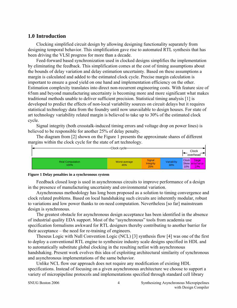
Feed-forward based synchronization used in clocked designs simplifies the implementation by eliminating the feedback. This simplification comes at the cost of timing assumptions about the bounds of delay variation and delay estimation uncertainty. Based on these assumptions a margin is calculated and added to the estimated clock cycle. Precise margin calculation is important to ensure a good yield on one hand and implementation efficiency on the other. Estimation complexity translates into direct non-recurrent engineering costs. With feature size of 65nm and beyond manufacturing uncertainty is becoming more and more significant what makes traditional methods unable to deliver sufficient precision. Statistical timing analysis [1] is developed to predict the effects of non-local variability sources on circuit delays but it requires statistical technology data from the foundry until now unavailable to design houses. For state of art technology variability related margin is believed to take up to 30% of the estimated clock cycle.
Signal integrity (both crosstalk-induced timing errors and voltage drop on power lines) is believed to be responsible for another 25% of delay penalty.
The diagram from [2] shown on the Figure 1 presents the approximate shares of different margins within the clock cycle for the state of art technology.
Worst-average45%
Signal Integrity
25%
Variability30%
Real Computation100%
ClockSkew10%
Clock cycleClock
overheadStage
imballance20%
Figure 1 Delay penalties in a synchronous system
Feedback closed loop is used in asynchronous circuits to improve performance of a design in the presence of manufacturing uncertainty and environmental variation.
Asynchronous methodology has long been proposed as a solution to timing convergence and clock related problems. Based on local handshaking such circuits are inherently modular, robust to variations and low power thanks to on-need computation. Nevertheless [so far] mainstream design is synchronous.
The greatest obstacle for asynchronous design acceptance has been identified in the absence of industrial quality EDA support. Most of the “asynchronous” tools from academia use specification formalisms awkward for RTL designers thereby contributing to another barrier for their acceptance – the need for re-training of engineers.
Theseus Logic with Null Convention Logic (NCL) [3] synthesis flow [4] was one of the first to deploy a conventional RTL engine to synthesize industry scale designs specified in HDL and to automatically substitute global clocking in the resulting netlist with asynchronous handshaking. Present work evolves this idea of exploiting architectural similarity of synchronous and asynchronous implementations of the same behavior.
Unlike NCL flow our approach does not require any modification of existing HDL specifications. Instead of focusing on a given asynchronous architecture we choose to support a variety of micropipeline protocols and implementations specified through standard cell library
SNUG Boston 2006 Synthesizing Asynchronous Micropipelines with Design Compiler
5
approach. We use Synopsys Liberty parser to interface with library specifications. Complex functionality, special purpose pins and other parameters inherent to asynchronous micropipeline stages are specified through the Liberty user-defined attributes. Unlike Haste from Handshake Solutions [5] and its public domain version Balsa [6] we target synthesis from unchanged standard synthesizable HDL specifications to allow reuse of legacy RTL designs. That is achieved by using Design Compiler (DC) as a specification front-end. Likewise, by using DC as a final netlist front-end we solve load/fan-out violations and ensure seamless interfacing with post-synthesis tools. Our flow implementation extends the original set of DC commands/procedures to reuse design environment as much as possible. Automatic fine grain pipelining not supported by other flows contributes very high performance.
We tested our flow on a number of examples with libraries implementing different micropipeline protocols and signaling schemes. As expected these proof-of-concept libraries developed using 180nm TSMC process exhibit good tolerance to variations. Implementations gracefully slow down at lower voltages. Synopsys NanoSim simulations show that our cells are functional with VDDs down to 0.6V. FIFO performance of 780MHz at nominal 1.8V drops to 135MHz at the safe 0.8V with 14.2x lower power consumption opening an ample space for power-performance trade-off. Designs with no data loops are automatically optimized to closely approach these rates affected by the amount of synchronization.
2.0 Asynchronous micropipelines Ivan Sutherland in [7] assigned the name micropipeline to “a particularly simple form of
event-driven elastic pipeline with or without internal processing. The micro part of this name seems appropriate to me because micropipelines contain very simple circuitry, because micropipelines are useful in very short lengths, and because micropipelines are suitable for layout in microelectronic form”. Pipeline is referred to as elastic if the number of data portions in a given pipeline can vary with time. Elastic pipelines can be implemented synchronously like for instance in superscalar processors. We are considering only asynchronous pipelines. Data path in asynchronous micropipeline may be implemented exactly the same way as in synchronous implementation while the clock is no longer global – it is computed locally for every register.
2.1 Delay models
Clocking allows designers to ignore timing, switching order, glitches and races when designing functionality. Timing behavior is designed separately thereby simplifying the complete design process. Contrariwise asynchronous circuits need to take into account all of the above since any of those problems may lead to incorrect computation. Redundancy is used in asynchronous implementations to explicitly define the execution order, eliminate glitches etc. The amount of redundancy depends on locality of timing assumptions. Localized assumptions are easier to meet in a design because they simplify timing convergence and provide better modularity. However ensuring the correctness of such assumptions can be costly because it requires more system redundancy at the functional level. Asynchronous design styles differ in the way they handle the trade-off between locality of timing assumptions and design cost.
The following are some of the most popular asynchronous design styles categorized based on their delay models: • Delay-insensitive (DI) circuits impose no timing assumptions, allowing arbitrary gate and
wire delays. Unfortunately, this class is limited and impractical.

SNUG Boston 2006 Synthesizing Asynchronous Micropipelines with Design Compiler
6
Timing assumptions localityR
edun
danc
y
MDSI
QDI
Synchronous
DI
Global
(cloc
k dom
ain)
None
Some f
orks i
soch
ronic
All fork
s iso
chron
ic
Logic
islan
d
Figure 2 Most popular delay models compared
• Speed-independent (SI) circuits assume that the wire delays are negligible compared to gate delays. Imposed for all wire forks such a restriction is becoming increasingly impractical for large designs and with shrinking feature size where the share of wire delays is growing.
• Quasi-delay-insensitive (QDI) circuits use assumptions similar to that of SI, but partition wires into critical and non-critical. No assumptions are made about non-critical wires while in critical wires the skew between different branches is assumed to be smaller than the minimum gate delay. Critical wire forks are also called isochronic forks.
• Matched delay (MD) circuits use delay lines to match the delay of a combinational logic island. The delay of the delay line is assumed to exceed the maximum delay of each is smaller than that of a reference logic path (usually called matched delay). Matched delays are implemented using the same gate library as the rest of the data path and they are subject to the same operating conditions (temperature, voltage). This results in consistent tracking of data path delays by matched delays and allows reducing design margins with respect to synchronous design. In the following section we consider the most practical for large systems and as such the
most popular QDI and MD design styles.
2.2 Matched delay versus data driven control
Much like in synchronous RTL, in MD and QDI circuits the data is transferred between state holding elements. In synchronous implementations those transfers are controlled by a global signal – clock. It arrives in defined periods of time and all data is assumed to be ready by the time of clock arrival. In MD and QDI implementations the transfer is controlled by local handshake. The sender has a way to determine the data readiness and to signal it to the receiver(s). The receiver has a way to acknowledge the receipt of data to the sender(s) as soon as the input data is processed and can be safely invalidated. Many handshaking protocols and implementations have been developed for both MD and QDI styles. They differ in degree of concurrency, implementation complexity and timing assumptions imposed on communication. The primary difference between MD and QDI styles lies in the way handshake implementation detects data readiness.
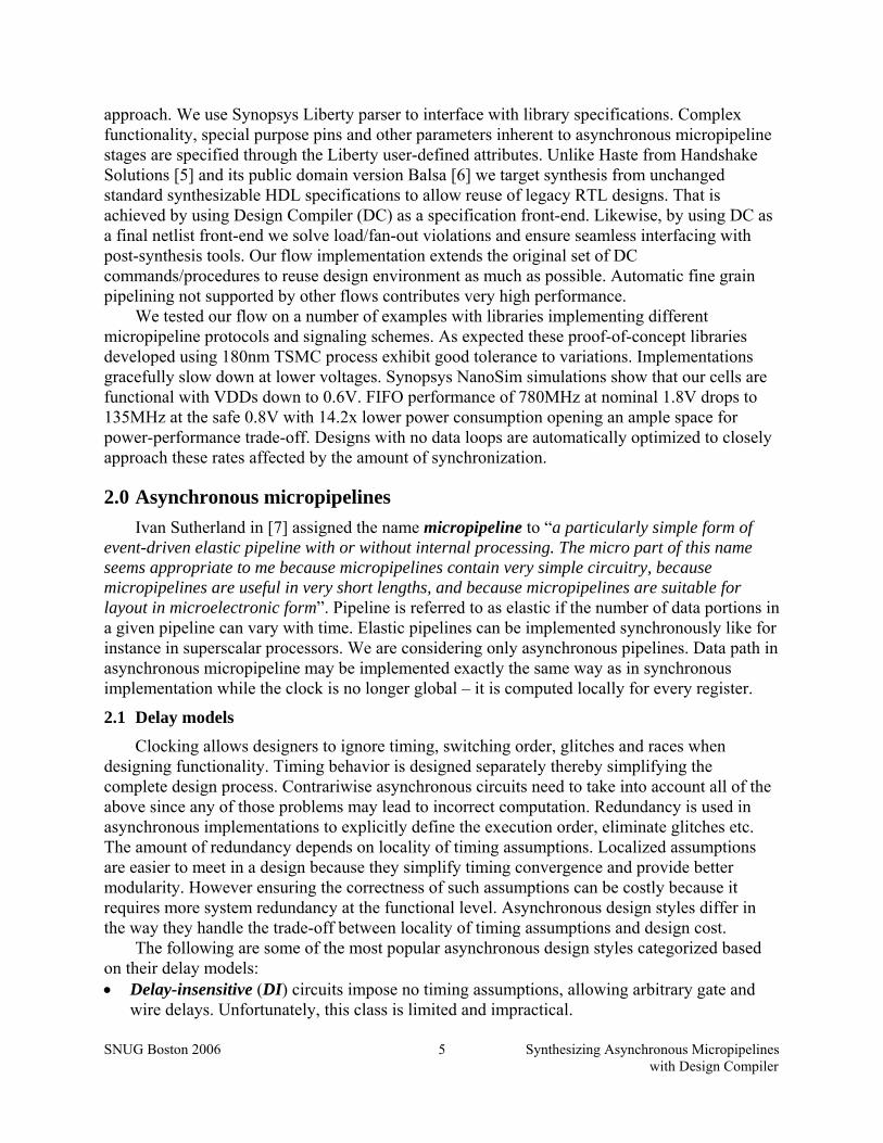
Matched delay, QDI and synchronous RTL design styles are compared on the Figure 3.
SNUG Boston 2006 Synthesizing Asynchronous Micropipelines with Design Compiler
7
Figure 3 Synchronous, matched delay and QDI design styles
Matched delay design style shown on the Figure 3b is similar to synchronous in that its design is based on estimating the time τCL it takes for all computations in combinational logic (CL) to complete. In synchronous implementation the maximum of all τCL with safety margin (Figure 1), set-up and hold time sums up to define the clock period. Unlikely in MD circuits the τCL with added margin to account for errors in estimation and variability is used to obtain the delay τMD of a delay line. The delay line can be placed next to the combinational (CL) island that it is matching. Then its variation is likely to follow that of the CL island. That allows using a smaller margin compared to the synchronous implementation where variations across the clock domain must be taken into account. Acknowledging the data receipt to the sender(s) ensures that the pace of the data transfer adjusts to delays caused by IR drop as well as other variations keeping the system functionality correct regardless of inter-stage variation.
Matched delay implementations often use synchronization at registration points since implementing the latch control and the delay line for every data bit would provide unnecessary area overhead. Because of this matched delay design style is often referred to as bundled data (BD).
Quasi-delay insensitive circuit examples are shown on the Figure 3c,d. QDI circuits do not rely on delay assumptions/estimations but instead encode data in such a way that one more value “no data” called spacer (or, sometimes, NULL) can be transmitted in addition to the actual data values. Most popular encodings are one-hot: dual-rail encoding with “00” being a spacer and “10”, “01” – TRUE and FALSE respectively and four-rail with “0000” reserved as a spacer and “1000” through “0001” – for data values “00” through “11”. Other possible combinations are invalid and can be used for testing, error detection etc. For the micropipelines using such data encoding it is usually assumed that every two consecutive data portions are separated with a spacer. Such distinct data portions are referred to as data tokens. Spacing data along with encoding allows determining data validity just by examining data wires. Such implementations are often called data driven. For the encodings mentioned above data validity check usually

SNUG Boston 2006 Synthesizing Asynchronous Micropipelines with Design Compiler
8
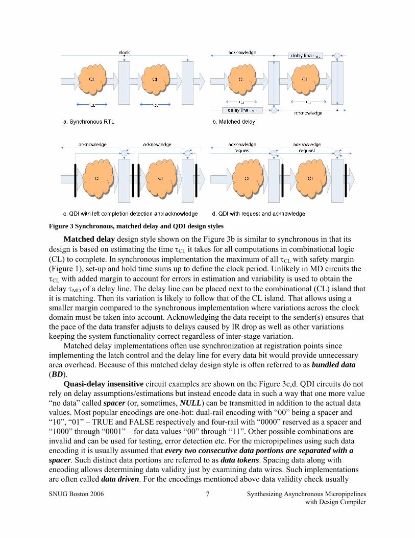
referred to as completion detection is performed using a NOR gate. In describing asynchronous circuits channel is often used to denote the set of wires dedicated to transmitting one codeword (corresponding to one bit of data for dual-rail one-hot or two data bits for four-rail one-hot encoding) and including all other wires (request, acknowledge) associated with this transmission. Synchronizing completion signals from several channels (Figure 4a) is usually done with Muller C-gate [8]. Karnaugh map, symbol and one of the implementations (quasi-static) for the C-gate are shown on the Figure 4c. C-gate is often used for synchronization thanks to its unique properties of synchronizing both falling and rising edges of its inputs. Figure 4b depicts an example of AND2 gate implementation as a QDI stage. It can use a request line – synchronized requests provided by the data senders as on the Figure 3d or the input completion detector (Figure 4a) as it is shown on the Figure 3c connected to the Req input.
In some implementations instead of using input completion detection the function is implemented with some redundancy to eliminate early propagation. In such cases they say that the output indicates inputs meaning that the output appears only after all valid inputs have arrived. An implementation can indicate data, spacer or both. The implementation on the Figure 4b does not indicate inputs either way. Indeed A0 or B0 high result in early evaluation (Z0 going high) without waiting for a data token arriving through the other input channel. Since logic inputs are only connected to the n-stack transistors the implementation does not indicate the spacer.
C
M
CDPC
ACK
F
RReq
RAck
parasitic capacitances
LAck
LReq
A0
B0
A1
B1
Z0
Z1
weak
C
CD2
(a) Input completion detection (b) AND2 stage implementation example
CD CD
(c) C-gate (quasi-static)
00
z
ab00 01 11 10
01
0 1 01 1 1
C
weak
a
b
z
Figure 4 Micropipeline cell implementation example
This two-input stage requires one two-input C-gate to synchronize completion signals from input channels. The completion detector complexity and latency is increasing fast with growing number of inputs. Building synchronization trees for large number of channels has been first presented in [9]. Implementing such synchronization at every registration point for an entire bus (8, 16 or more bits) induces large area and latency overhead. This is one of the primary reasons for on-need only synchronization in data driven implementations.
Every micropipeline stage has built in memory for one token while the data propagation is controlled by handshakes. In popular Return-To-Zero (RTZ) protocols data tokens need to be separated by spacers allowing storing N tokens in a 2N stage FIFO. Such stages are called half-buffer (HB) stages. Alternatively a stage can be implemented as a full-buffer (FB) stage allowing storing N tokens in N-stage FIFO.
SNUG Boston 2006 Synthesizing Asynchronous Micropipelines with Design Compiler
9
3.0 Asynchronous micropipeline synthesis tools The main problems for asynchronous methodology acceptance are often referred to be the
following: • absence of industrial quality EDA support; • significantly different methodology requiring re-training of engineers and re-engineering
legacy designs; • low benefits compared to required investment; The progress in VLSI technology (shrinking the feature size, lowering power supply voltage
etc) leads to increase in variability and thereby complicates STA and exacerbates clock related problems thereby slowly changing the third – most important economical problem. Academia and several start-ups were meanwhile tackling the first two.
3.1 Synchronous-to-Asynchronous Direct Translation (SADT) tools
Complete EDA support cannot realistically be created from scratch. In these circumstances existing EDA tools are being reused as much as possible. So called Synchronous-to-Asynchronous Direct Translation (SADT) is one of such approaches. SADT takes advantage of architectural similarity between synchronous and asynchronous implementations of the same behavior. They start from a conventional synthesizable HDL specification, synthesize it into a gate-level netlist using off-the-shelf logic synthesis tools, and then translate it into asynchronous implementation. Translation usually does not alter the system architecture and simply replaces global clocking by asynchronous handshaking.
Theseus Logic with their Null Conventional Logic (NCL) [4] design flow pioneered SADT approach. NCL used a proprietary library comprising heavy threshold gates to implement QDI pipelines of the same granularity as in the original synchronous netlist. NCL circuits suffer from synchronization delay and area overhead at registration points while the synthesis flow required manual modifications of the original HDL specification for NCL synthesis.
Phased Logic [10] replaces every combinational gate with its dual-rail implementation. Unlike most asynchronous pipeline implementations (that use one-hot data encoding) in Phased Logic the two rails carry data and phase. Such encoding does not require spacers for tokens separation since every two consecutive code words are distinct regardless of data. This gives Phased Logic a potential for reducing dynamic power consumption at the price of using specialized gates and complex synthesis procedure.
De-synchronization [11] – the most recent synthesis approach using conventional standard cell libraries and substituting global synchronization at registration points by local handshaking between registration points. It is primarily targeted at matched delay pipeline architecture that allows for virtually no overhead compared to the original synchronous implementation still offering robustness to variations.
Weaver – our synthesis flow is also a SADT flow. It implements automatic synthesis of fine-grain micropipeline implementations using a user specified micropipeline library. Weaver flow [12, 13] supports large variety of asynchronous handshake protocols and data encodings while it is best suited the protocols with weak or no timing assumptions on handshaking.
3.2 Other tools automating design of asynchronous circuits
Academia and industry developed a number of tools automating design of asynchronous circuits. The tools selected for this section solve design problems different from our design flow.

SNUG Boston 2006 Synthesizing Asynchronous Micropipelines with Design Compiler
10
These are mature asynchronous circuits design tools that can even be used in conjunction with the Weaver flow. For instance Petrify can be helpful for developing a handshake protocol and/or its implementation while CHAINworks – to interconnect the synthesized designs into a SoC.
Petrify [14] from Polytechnic University of Cataluña is one of the widely used tools for manipulating concurrent specifications and synthesizing primarily SI asynchronous circuits from Signal Transition Graphs (an event causality based formalism for specifying concurrent behaviors with choice), State Graphs and some other specifications. By taking into account the environment and circuit behavior specification Petrify is able to synthesize high quality implementations in a number of implementation styles. Algorithms implemented in Petrify manipulate the state space of the circuit that grows exponentially with the number of signals. Due to complexity limitation Petrify is best suited for synthesizing small control circuits.
Haste from Handshake Solutions [5] is a development of an earlier (created in and used exclusively by Philips) asynchronous circuits design tool called Tangram. Haste is also a language [15] based on Communicating Sequential Processes (CSP) [16] – the formalism well suited for designing asynchronous architectures [6, 17]. Haste syntax is similar to Verilog but unlike Verilog it features explicit constructs for parallelism, communication, and hardware sharing. Specifications written in Haste can be compiled to behavioral Verilog for functional verification. Its main advantage is the ability to achieve all the advantages of asynchronous implementation by controlling the activation of both control and data path units (and hence power and energy consumption) at a very fine level.
CHAINworks from Silistix [18] unlike other tools mentioned in this section is not designed to synthesize general purpose circuits but rather focuses in one of the areas where self-timed delay insensitive and therefore variation tolerant communication is most beneficial – CHip Area INterconnect. Scalable packet switching on-chip network is built from delay-insensitive links using 5-rail one-hot encoding encoded data channel with a dedicated acknowledge line. Resulting implementation is known as Globally Asynchronous Locally Synchronous (GALS). The company provides user-friendly tools that support popular IP cores and bus interfaces to synthesize interconnect with user specified topology.
4.0 Synchronous netlist to micropipeline re-implementation The idea behind our synthesis flow is that of SADT – substitution based re-implementation
of an RTL netlist as a micropipeline. This RTL netlist is synthesized with Design Compiler using a virtual library (VL) – an imaginary single-rail conventional library that does not exist in silicon (or other tangible implementation) but available to the Design Compiler. As long as the library for which the netlist has been synthesized is functionally equivalent to the micropipeline library re-implementation remains substitution based and therefore computationally inexpensive.
In this paper we avoid including any formal models of micropipeline or synchronous implementations or proofs of correctness instead giving the intuition behind re-implementation. Petri net based models and a sketch of correctness proof are available in [12, 13].
4.1 Combinational case
The main property of combinational logic is that it is memoryless i.e. the output is entirely dependent on its inputs. Such circuits are mapped to functionally equivalent micropipeline stages initialized to spacers. This way the first data token to appear on the output of the micropipeline implementation is a valid data token propagated from the primary inputs.

SNUG Boston 2006 Synthesizing Asynchronous Micropipelines with Design Compiler
11
We start from a combinational case as it is the simplest. As long as VL is functionally equivalent to our micropipeline set of stages all that needs to be done is:
• substituting the gate instances by the corresponding stages, • interconnecting channel signals and reset. Mapping of a small netlist consisting of an AND2 gate is shown on the Figure 5. The cell
found in the synchronous netlist is available in the virtual library so its functionality is known. A functionally equivalent cell initializable to spacer is always found in the stage library with its dependencies annotated (Figure 5b) for level assignment (section 6.1.2). Assume that the only available functionally equivalent micropipeline cell has one request line shared between input channels (like on the Figure 4b). After the model has been identified the micropipeline implementation is generated as it is shown on the Figure 5c assuming the micropipeline protocol with one request and one acknowledgement line.
The model of our module shown on the Figure 5b depicts the model of the AND2 gate with two input channels and one output channel that depends on each of the outputs and each of the dependencies (aka timing arcs) is 1 HB stage long. We use such models through the paper to present the structure of more complex micropipeline blocks.
The design interface is expanded to include all wires used in the channels (in our example data[0], data[1], request and acknowledge). The design in our example (Figure 4) needs two synchronizers (usually C-gates): for input channel req and output channel ack signals. Input requests and input acknowledgements are fed from environment. With no information about the environment initialization req synchronizer (join) is conservatively chosen initializable to spacer (shown as a circle with N inside) and the ack synchronizer (fork) – initializable to data (shown as a circle with D inside). Reset signals of necessary polarity are connected to the reset inputs of the instantiated cells.
AND2
X
Y
A
B
micropipeline stageF0=A0+B0,F1=A1&B1
ACK
PC
CD
F MB
A X
Z
reqack
reqack
ackreq
reset
spaced data forkjoin
spaced data
spaced data
spaced data
(a) Virtual library cell (b) Model (c) Micropipeline implementation in general
11
X
Y
A
B
ackreq
DN
Figure 5 Combinational logic mapping example: AND2 with fan-out 2
Intuition behind the synchronizers initialization is the following. Suppose our design (Figure 4) is instantiated in the environment where the consumers are stages initialized one to data and the other to spacer. In these circumstances initializing the ack synchronizer to be signaling spacer may lead to a data token propagating to AND2 stage before the previous token was removed from the following stage (initialized to a data token). This will violate the handshake protocol and may lead to data loss or deadlock depending on the stages implementation. As a rule acknowledge synchronizer is initialized to active data level. Following the inverse argument it is easy to see that request synchronizers must be initialized to the level corresponding to spacer. These synchronizer initialization considerations are correct if and only if for every two connected HB stages only one is initialized to a data token.
Inverters in dual-rail implementations using one-hot data encoding are implemented as a zero-area wire crossing. That allows for reducing the micropipeline library size by including only one from every pair of dual gates. De-Morgan transformation is used to instantiate such cells.

SNUG Boston 2006 Synthesizing Asynchronous Micropipelines with Design Compiler
12
4.2 Constants and open outputs
We call micropipeline deterministic as long as data (token rather than value) propagation does not depend on the contents of data. In deterministic micropipeline every module consumes one token per input channel to produce one token per output channel. That assumption causes a deadlock if channel wires are simply hardwired to VDD (or ground) or left open. Token source – simple circuit (Figure 6) that produces data tokens on its only output in compliance with the micropipeline handshake protocol, and token consumer acknowledging outgoing tokens are used in such cases to ensure deadlock freedom.
X
gnd
(c) Constant feeder(b) Model
req
ack
data(0)
data(1)
X
(a) Constant
X00
Figure 6 Constant "0" mapping example (assuming that: request and acknowledgement are present and both are active low, data encoding is one-hot with “00” reserved for spacer).
The circle with “0” inside on the Figure 6b signifies that the token source produces series of “0” data tokens.
4.3 Synchronous netlists with memory
Assuming that the only state holding elements included in the virtual library are d-flip-flops and d-latches three types of implementing a state holding circuit remain: using a flip-flop, latch or a combinational loop. Here we consider the first two.
Consider d-flip-flop as two sequentially connected orthogonally clocked d-latches. Then both a d-latch and d-flip-flop connected to clock pass the input data value to its output in one and two clock edges respectively. From another point of view a D-flip-flop has two memory elements with alternating store/transparent states. This allows for safe data propagation of N data tokens through N d-flip-flops long FIFO or a FIFO consisting of 2N memory elements.
Every micropipeline stage has built in memory for one token while the data propagation is controlled by handshakes. Data tokens need to be separated by spacers making it possible to store N tokens in a 2N stage FIFO. Such stages are called half-buffer (HB) stages. Alternatively a stage can be implemented as a full-buffer (FB) stage allowing storing N tokens in N-stage FIFO.
Intuitively these are the reasons for mapping each of the d-latches onto single half-buffer micropipeline stage implementing identity function.
Orthogonal clocking makes one of the latches initially transparent while the other can be initialized. This initialized value of a non-transparent latch is propagated through the output channel. Initialization is preserved in micropipeline implementation by using stages initialized to a data value. The mapping is shown on the Figure 7. Note the depth of dependency, initialization and the distance of the stage with a token from the output of the module on the Figure 7b,d.
Identity function stages (or buffer stages) inferred from clocked flip-flops and latches perform no data processing and in many cases are optimized out as it is described in section 6.1.2 while always preserving initialization.
SNUG Boston 2006 Synthesizing Asynchronous Micropipelines with Design Compiler
13
(a) D-latch (b) D-latch model (c) Micropipeline implementation in general
XA
Q
QSET
CLR
D
LD-latch
A
reset
clock
Xmicropipeline stageF0=A0, F1=A1Initially D1
ACK
PC
CD
F M
A X
reset
(d) D-flip-flop (e) D-flip-flop model (f) Micropipeline implementation in general
XA
Q
QSET
CLR
D
LDFF
A
reset
clock
X
A Xreqack
reset
spaced data
micropipeline stageF0=A0, F1=A1Initially D1
ACK
PC
CD
F M
micropipeline stageF0=A0, F1=A1Initially N
ACK
PC
CD
F M
2 01
1 01
reqack
spaced data
reqack
spaced data
reqack
spaced data
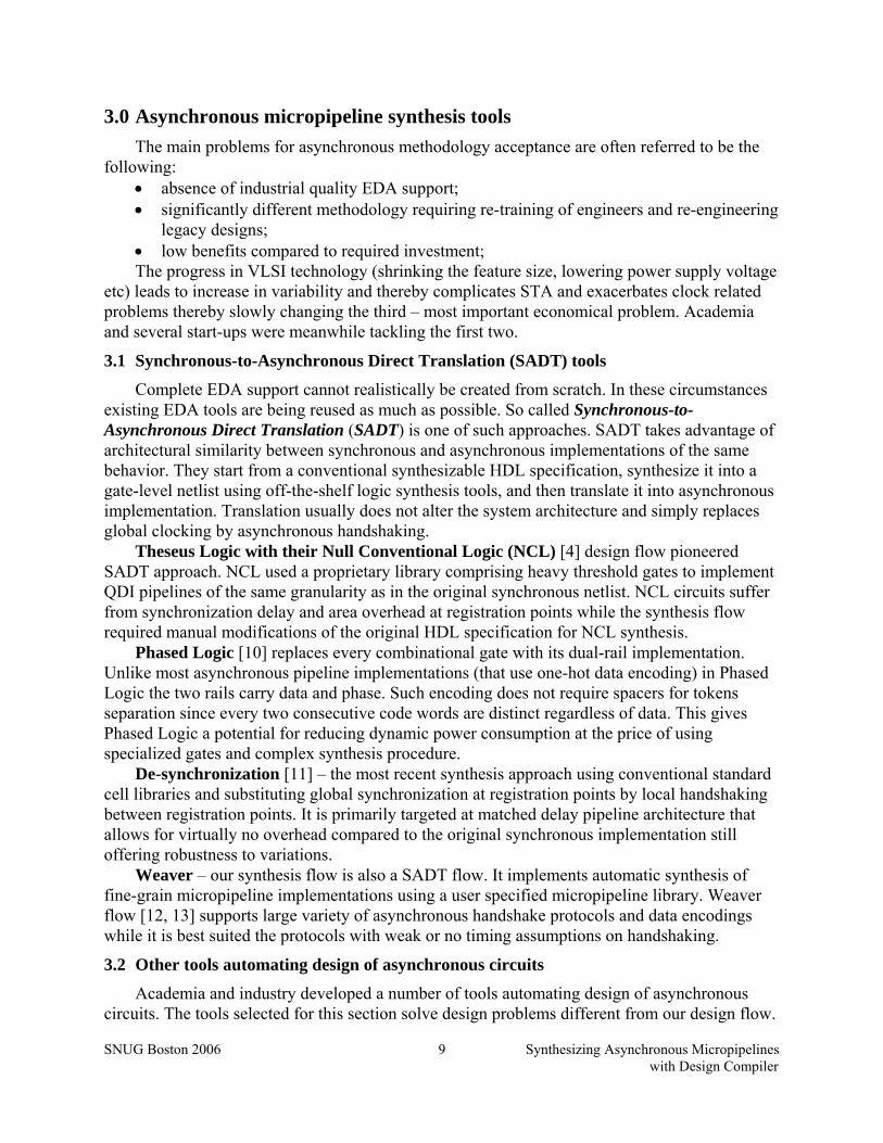
Figure 7 Mapping clocked d-latches and d-flip-flops to micropipeline
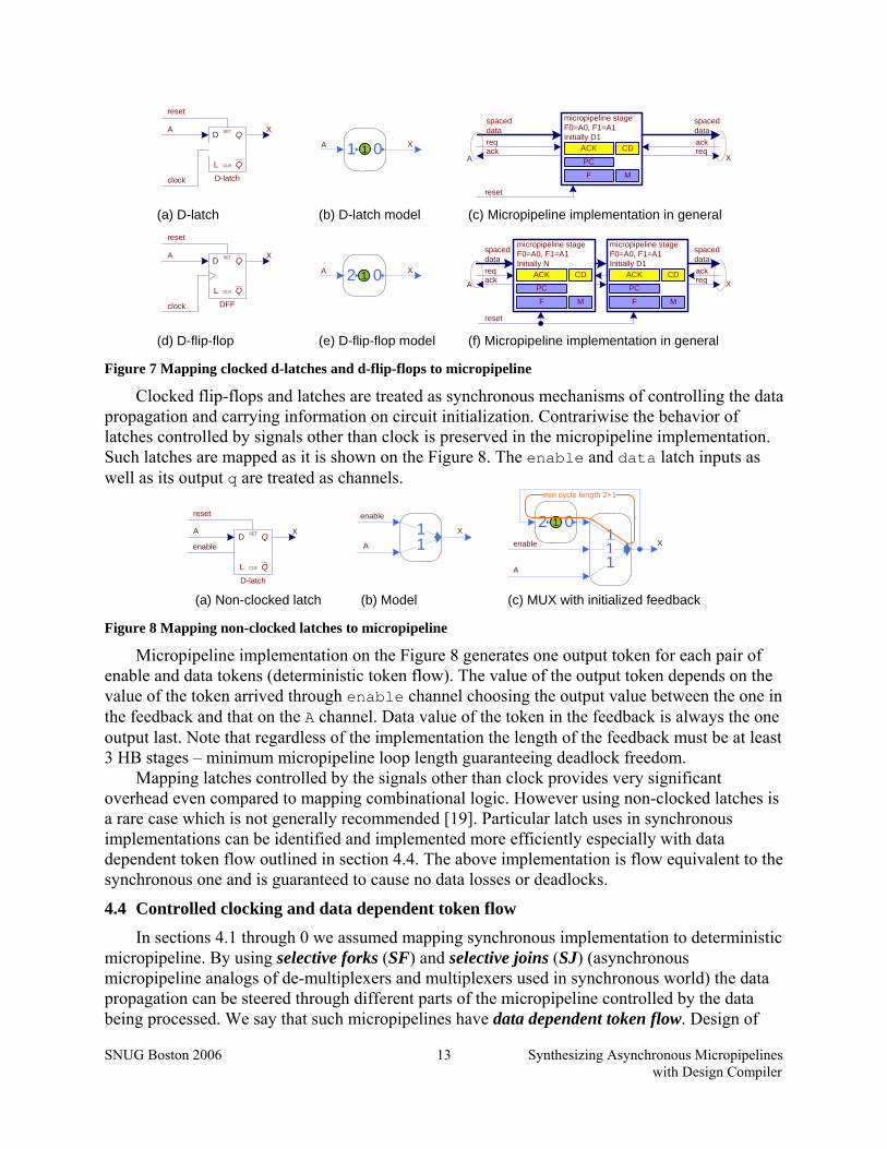
Clocked flip-flops and latches are treated as synchronous mechanisms of controlling the data propagation and carrying information on circuit initialization. Contrariwise the behavior of latches controlled by signals other than clock is preserved in the micropipeline implementation. Such latches are mapped as it is shown on the Figure 8. The enable and data latch inputs as well as its output q are treated as channels.
Q
QSET
CLR
D
LD-latch
A
reset
enable
X X
A111
enable
A
X
min cycle length 2+1
2 01
(c) MUX with initialized feedback
11
enable
(b) Model(a) Non-clocked latch Figure 8 Mapping non-clocked latches to micropipeline
Micropipeline implementation on the Figure 8 generates one output token for each pair of enable and data tokens (deterministic token flow). The value of the output token depends on the value of the token arrived through enable channel choosing the output value between the one in the feedback and that on the A channel. Data value of the token in the feedback is always the one output last. Note that regardless of the implementation the length of the feedback must be at least 3 HB stages – minimum micropipeline loop length guaranteeing deadlock freedom.
Mapping latches controlled by the signals other than clock provides very significant overhead even compared to mapping combinational logic. However using non-clocked latches is a rare case which is not generally recommended [19]. Particular latch uses in synchronous implementations can be identified and implemented more efficiently especially with data dependent token flow outlined in section 4.4. The above implementation is flow equivalent to the synchronous one and is guaranteed to cause no data losses or deadlocks.
4.4 Controlled clocking and data dependent token flow
In sections 4.1 through 0 we assumed mapping synchronous implementation to deterministic micropipeline. By using selective forks (SF) and selective joins (SJ) (asynchronous micropipeline analogs of de-multiplexers and multiplexers used in synchronous world) the data propagation can be steered through different parts of the micropipeline controlled by the data being processed. We say that such micropipelines have data dependent token flow. Design of
SNUG Boston 2006 Synthesizing Asynchronous Micropipelines with Design Compiler
14
selective forks and joins for various micropipeline styles is considered for instance in [20, 21]. Data dependent token propagation has been used in asynchronous circuits for a long time to reduce dynamic power consumption by means of on-need only computation.
Clock gating (CG) is a dynamic power saving technique used in synchronous designs. It consists in data dependent switching off clocking (and hence data propagation) in the circuit domain(s) unused for current computation. For instance it is reasonable to turn off the multiplier for as long as there are no instructions involving multiplication in the queue. CG is automated in Synopsys Power Compiler [22].
Selective forks and joins can be used to choose alternative computation branches. Synchronous implementations are often designed to compute both results and choose the right one using a MUX. It is the stringent power constraints that make it necessary to eliminate unnecessary switching activity by using clock gating or operand isolation (also supported by Synopsys Power Compiler [22]), etc.
The data path points for inserting selective forks and joins (that can be safely inserted only in pairs controlled by the same channel) are identified by transitive backtracking from the MUXes in the design. Clock gating simplifies the branching point identification since the set of deactivated registers is immediately known. Similarly with operand isolation both branching and merging points (MUX) are easily identified.
CG implementation is lower complexity compared to selective fork that must be used for every data channel compared to one clock gate used per register bank. Selective join complexity is usually higher than deterministic multiplexer implementation. Increased area affects the power consumption that must be estimated for every particular case prior to choosing whether or not to use the data dependent token flow.
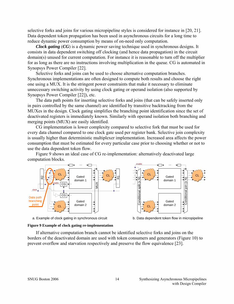
Figure 9 shows an ideal case of CG re-implementation: alternatively deactivated large computation blocks.
a. Example of clock gating in synchronous circuit b. Data dependent token flow in micropipeline
Gated domain 1
enable
......CL...
Gated domain 2... ...CL
...
...
...
...CL...
Con
ditio
nal s
plit
(x N
)
Con
ditio
nal j
oin
(x N
)Gated domain 1
CGenable
clock
......CL...
Gated domain 2... ...CL
CG
...
...
...
...CL
R1
R2
MU
X
Data path branching
point
Figure 9 Example of clock gating re-implementation
If alternative computation branch cannot be identified selective forks and joins on the borders of the deactivated domain are used with token consumers and generators (Figure 10) to prevent overflow and starvation respectively and preserve the flow equivalence [23].

SNUG Boston 2006 Synthesizing Asynchronous Micropipelines with Design Compiler
15
Token consumer
0
0
enable
Din
Dout
(b) SJ with initialized feedback (c) SJ with const generator(a) SF with token consumer
2 01
0
00
Din
enable
Dout
01
enable
Dout
Din
0
00
Figure 10 Selective fork and joins with token sources/sinks
SJ with feedback (Figure 10b) is used if it is important that the value stored in the last register of the deactivated bank is sampled by the circuit connected to its output (default). Simplified implementation (Figure 10c) can be used otherwise if the data is not important.
4.5 Micropipeline implementation correctness
Similarly to [11] we say that micropipeline implementation is correct if and only if it is deadlock free and flow equivalent (originally from [24]) to the synchronous implementation used for re-implementation. For deterministic micropipelines these conditions are defined as follows.
Deadlock freedom means that the micropipeline does not halt as long as • input data is fed (in compliance with implemented handshake protocol) to all
micropipeline input channels; • output data is acknowledged (in compliance with implemented handshake protocol) on all
output channels; Flow equivalence requires that the sequences of data tokens received from corresponding
synchronous and micropipeline implementations are identical for corresponding output channels if the data token sequences supplied to the corresponding input channels are identical.
Correctness of the micropipeline implementations with data dependent token flow is expressed in a similar fashion but since some of the tokens are not propagated through some of the paths (function of the circuit logic and input data) we apply the above notions for the informative data tokens.
For an example of an informative token consider a latch on the output of a computation block. Such latches are used to trigger the last correct (or informative value) if the computation may take several clock cycles. In deterministic case a latch is mapped as it is shown on the Figure 8. In micropipeline with data dependent token flow instead of generating the last token as many times as it takes to compute the next one we use a SJ implementation shown on the Figure 10c to generate only one (informative) token per correct value.
4.6 Required library contents
Now that the basic synchronous-to-micropipeline mappings are presented we define the set of modules – micropipeline building blocks that must be present in the library to enable reimplementation of any netlist.
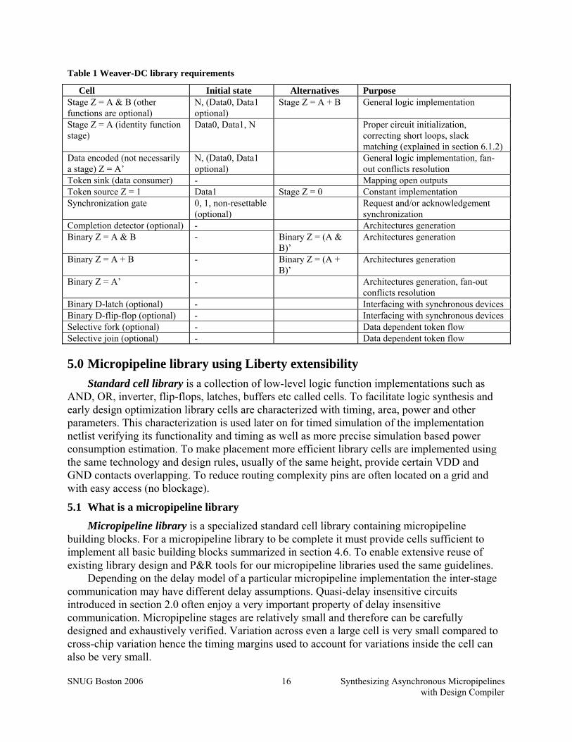
Required micropipeline library contents include basic micropipeline elements – stages and synchronization gates as well as general purpose binary logic gates used in the Weaver flow to solve fan-out conflicts and generate some of the above architectures not found in the library. Required micropipeline library contents are summarized in the Table 1.
SNUG Boston 2006 Synthesizing Asynchronous Micropipelines with Design Compiler
16
Table 1 Weaver-DC library requirements
Cell Initial state Alternatives Purpose Stage Z = A & B (other functions are optional)
N, (Data0, Data1 optional)
Stage Z = A + B General logic implementation
Stage Z = A (identity function stage)
Data0, Data1, N Proper circuit initialization, correcting short loops, slack matching (explained in section 6.1.2)
Data encoded (not necessarily a stage) Z = A’
N, (Data0, Data1 optional)
General logic implementation, fan-out conflicts resolution
Token sink (data consumer) - Mapping open outputs Token source Z = 1 Data1 Stage Z = 0 Constant implementation Synchronization gate 0, 1, non-resettable
(optional) Request and/or acknowledgement
synchronization Completion detector (optional) - Architectures generation Binary Z = A & B - Binary Z = (A &
B)’ Architectures generation
Binary Z = A + B - Binary Z = (A + B)’
Architectures generation
Binary Z = A’ - Architectures generation, fan-out conflicts resolution
Binary D-latch (optional) - Interfacing with synchronous devices Binary D-flip-flop (optional) - Interfacing with synchronous devices Selective fork (optional) - Data dependent token flow Selective join (optional) - Data dependent token flow
5.0 Micropipeline library using Liberty extensibility Standard cell library is a collection of low-level logic function implementations such as
AND, OR, inverter, flip-flops, latches, buffers etc called cells. To facilitate logic synthesis and early design optimization library cells are characterized with timing, area, power and other parameters. This characterization is used later on for timed simulation of the implementation netlist verifying its functionality and timing as well as more precise simulation based power consumption estimation. To make placement more efficient library cells are implemented using the same technology and design rules, usually of the same height, provide certain VDD and GND contacts overlapping. To reduce routing complexity pins are often located on a grid and with easy access (no blockage).
5.1 What is a micropipeline library
Micropipeline library is a specialized standard cell library containing micropipeline building blocks. For a micropipeline library to be complete it must provide cells sufficient to implement all basic building blocks summarized in section 4.6. To enable extensive reuse of existing library design and P&R tools for our micropipeline libraries used the same guidelines.
Depending on the delay model of a particular micropipeline implementation the inter-stage communication may have different delay assumptions. Quasi-delay insensitive circuits introduced in section 2.0 often enjoy a very important property of delay insensitive communication. Micropipeline stages are relatively small and therefore can be carefully designed and exhaustively verified. Variation across even a large cell is very small compared to cross-chip variation hence the timing margins used to account for variations inside the cell can also be very small.
SNUG Boston 2006 Synthesizing Asynchronous Micropipelines with Design Compiler
17
Implementing a complete micropipeline stage in one cell ensures the physical implementation functionality regardless of placement, routing, manufacturing and environmental variations since the only timing assumptions are those about delays inside the library stage. Note here that the function implementation in such stages is usually dynamic domino-like what eliminates the need for a data dependent p-stack and thereby allows for low latency and area efficient implementations of cells with large number of inputs.
This approach is feasible only for very fine-grain pipelines where the stages are gate-level. Other drawbacks of such implementation are the following:
• The stage-cell size even for fine-grain pipelines can significantly exceed the size of smaller cells such as synchronization cells, token consumers and producers. Such variations in cell sizes although potentially mitigated by using double high for large cells still lead to less efficient placement and even more increased area.
• High overhead of handshake implementation. • Pipeline stage granularity cannot be changed. Alternatively library cells implement stage building blocks. This approach is more flexible
since it is appropriate for variable pipeline granularity. It can also be more efficient from the placement efficiency point of view. On the downside the placement and routing may have to be constrained to satisfy in-stage timing assumptions.
In the absence of synthesis tools asynchronous micropipeline libraries are developed in the form of templates (like [25-27]). Two of them [26, 27] are implemented in TSMC 0.25μm process and available through MOSIS.
We did not use the libraries presented in [25-27] and instead developed our own proof-of-concept libraries. One of them – M2PCHB is similar to PCHB (from [21]). It uses dual-rail binary data encoding with acknowledge signaling and similar implementation but equipped with input completion detection to ensure delay insensitive communication. Another one – Balanced Symmetric with Discharge Tree (BSDT) [28] uses request line to signal data validity (what imposes an easy to satisfy inter-stage communication timing assumption but saves area), dual-rail data encoding and acknowledge wire. It is designed specifically for secure applications requiring that the cell power consumption is data independent.
5.2 Micropipeline vs. conventional standard-cell library characterization
Precise timing characterization is crucial for the RTL synthesis to balance the pipeline stages across the clock domain to ensure correct functionality while maintaining efficiency – maximum achievable amount of computation per clock cycle.
Micropipelines (introduced in section 2.0) are handshake based. Handshakes explicitly signal data validity to the receivers and acknowledge data portion consumption to the sender(s). That eliminates the impact of timing on the circuit functionality. Timing and power characterization of micropipeline cells is still important for quick performance and power consumption estimation of large systems.
Data driven micropipelines use data encoding to determine data validity (see section 2.2). That requires additional wires to transmit one bit value. The notion of channel in micropipelines replaces that of a wire.
Multiple outputs and the complexity of handshake implementation result in the cell functionality unsupported by the Library Compiler (LC). Current version restrictions include very limited support for multiple-output gates with memory, etc. However the exact truth tables

SNUG Boston 2006 Synthesizing Asynchronous Micropipelines with Design Compiler
18
for the handshake implementation are not necessary for the synthesis engine assuming the handshake protocol is uniform across the design.
Data encoding that allows transmitting additional (spacer) information increase the functional block complexity. For example with one-hot dual-rail encoding every gate implements direct and dual functions to provide direct and inverse outputs independently. In general the function implementation is data encoding and implementation dependent. Under assumption of uniform data encoding across the design it is sufficient to represent the gate functionality with its direct function.
In order to generalize the micropipeline support and simplify re-implementation we abstract as much as possible from the protocol, data encoding and its implementation. In section 5.3 we introduce the Liberty extensions that allow library designers specifying channels, particular pins that belong to channels and their role in the channel (much like the clock_pin, clock_gate_enable_pin, etc Liberty attributes specify the roles of signals in synchronous gates). Requests – the signals propagating in the same direction as data and acknowledgements – the signals propagating in the opposite direction belong to one or more channels. Data wires (the number of data wires per channel can be specified) belong to only one channel. The functionality of a micropipeline cell is expressed either through the cell type (synchronizer etc) following the practice of using attributes like clock_gating_integrated_cell or as an equation with channels (instead of pins) as its variables.
At this point our tool supports only gate-level pipelining therefore the timing characterization is currently only used for simulation. However the length of in-module dependencies in HB stages is important to ensure the pipeline deadlock freedom. In addition channel capacity has direct impact on the implementation performance (see slack matching in sections 6.1.2 and 7.2). That requires specifying these dependencies between input and output channels similarly to timing arcs. Some of the micropipeline Liberty extensions are presented in the section 5.3. For the complete list of Liberty extensions recognized by the Weaver engine refer to [29] found with the Weaver flow distribution.
5.3 Liberty extensions for micropipeline characterization
With protocol and data encoding uniformity assumptions building a micropipeline from a dataflow is reduced to simple mapping. Channel interconnection is defined by the data flow while the particular wires in the channel are interconnected based on their type. To automate interconnection for every pin we specify its micropipeline type and the channel(s) it belongs to.
An example of the use of our Liberty extensions to represent a spacer initialized micropipeline stage implementing AND2 functionality is shown on the Figure 11. Timing and power characterization was dropped to save space and improve readability.
User specified attributes introduced to characterize micropipeline stages start with the gtl_ prefix1. They specify parameters that are not defined in [30]. The attribute names are self-explanatory for most of the time but some deserve mentioning. gtl_channel specifies the names of the list of channels (separated by a whitespace) this particular pin belongs to. Data pins always represent one channel while the request and acknowledge pins may signal a set of channels. In our example on the Figure 11 l_ack acknowledges both A and B channels like on the Figure 4 (except the cell described on the Figure 11 does not have request lines). 1 GTL stands for “Gate Transfer Level” – as we presented the fine-grain micropipeline synthesis framework in our previous publications [12,13]. As opposed to RTL synthesis we used GTL to emphasize data-dependent only synchronization (no synchronization at registration points) and very-fine-grain – gate level pipelining.

SNUG Boston 2006 Synthesizing Asynchronous Micropipelines with Design Compiler
19
Similarly to the combinational gate functionality expressed using function Liberty
attribute high-level functionality is specified by gtl_function pin attribute. Likewise gtl_depth attribute in the timing group specifies the length of this particular timing arc in half-buffer stages. Depth is used for level assignment described below in section 6.1.2 and important for insuring deadlock freedom and optimizations. Timing arc specification is unchanged. Potentially used for slack fine tuning timing is not used during re-implementation at the moment.
gtl_active_level if specified for request or acknowledge pin is used to specify the logic level indicating data token (spacer is indicated otherwise). If gtl_active_level is not
cell ("AND2_N") { area : 223.91; gtl_cell : "GEN"; bus (A) { bus_type : "BusType00"; direction : "input"; pin ("A[0]") { gtl_level : 0; gtl_channel : "A"; gtl_channel_type : "Data"; gtl_pin_type : "D0"; fanout_load : 1; } pin ("A[1]") { gtl_level : 0; gtl_channel : "A"; gtl_channel_type : "Data"; gtl_pin_type : "D1"; } } bus (B) { bus_type : "BusType00"; direction : "input"; pin ("B[0]") { gtl_level : 0; gtl_channel : "B"; gtl_channel_type : "Data"; gtl_pin_type : "D0"; fanout_load : 1; } pin ("B[1]") { gtl_level : 0; gtl_channel : "B"; gtl_channel_type : "Data"; gtl_pin_type : "D1"; } } pin ("Z_ack") { direction : "input"; gtl_pin_type : "A"; gtl_channel : "Z"; gtl_active_level : "0"; } pin (rst1) { direction : "input"; gtl_pin_type : "Reset"; gtl_active_level : "0"; } pin (rst2) { direction : "input"; gtl_pin_type : "Reset"; gtl_active_level : "1"; }
Page 1
bus (Z) { bus_type : "BusType00"; direction : "output"; pin ("Z[0]") { gtl_level : 1; gtl_channel : "Z"; gtl_channel_type : "Data"; gtl_pin_type : "D0"; max_fanout : 2; gtl_function : "(A & B)"; gtl_initial_value : "N"; gtl_ch_initial_value : "N"; timing () { related_pin : "A[0]"; gtl_related_channel : "A"; gtl_depth : 1; } timing () { related_pin : "B[0]"; gtl_related_channel : "B"; gtl_depth : 1; } } pin ("Z[1]") { gtl_level : 1; gtl_channel : "Z"; gtl_channel_type : "Data"; gtl_pin_type : "D1"; gtl_function : "(A & B)"; gtl_initial_value : "N"; gtl_ch_initial_value : "N"; timing () { related_pin : "A[0]"; gtl_related_channel : "A"; gtl_depth : 1; } timing () { related_pin : "B[0]"; gtl_related_channel : "B"; gtl_depth : 1; } } } pin ("l_ack") { direction : "output"; gtl_pin_type : "A"; gtl_channel : "A B"; max_fanout : 1; gtl_active_level : "0"; gtl_initial_value : "N"; } }
Page 2
Figure 11 Liberty micropipeline stage representation example
11
a
bz

SNUG Boston 2006 Synthesizing Asynchronous Micropipelines with Design Compiler
20
specified for a request or acknowledge pin the default is used that is specified with gtl_ack_data_received_level or gtl_req_data_ready_level library level attribute respectively. Inverter is inserted during re-implementation if the active levels of pins to be connected do not match. Specified for reset pins gtl_active_level specifies the logic level used to reset the cell. Micropipeline cells are complex and two (active level “1” and active level “0”) reset inputs are used sometimes to save the cell area. gtl_active_level attribute is ignored if specified for the pins of other types.
gtl_ch_initial_value pin attribute can be specified for any channel, request, acknowledge or data pin and specifies the value the corresponding channel is initialized to. “N” signifies spacer (stands for NULL) while “1” and “0” signify data values “1” and “0” respectively. Specifying different values for two pins representing the same channel causes an error.
gtl_cell cell attribute specifies the cell type. If this attribute is not specified the cell is treated a standard cell conforming to the Liberty specification [30]. This attribute is a string type that takes a set of predefined values. Most often used are “gen”, specifying a complete generic micropipeline stage cell or lower level hierarchical module, and “sync”, specifying the cell as a cell used for handshake synchronization.
gtl_slack_factor is a library scope integer attribute to define the default slack factor for use with the library (see Slack matching in sections 6.1.2 and 7.2). For the complete list of Liberty extensions recognized by the Weaver engine refer to [29].
5.4 Library components and installation
A standard cell library provides a designer with information to synthesize the implementation netlist, estimate the design area, performance and power consumption, simulate it on HDL level to verify functionality and timing and obtain simulation based power consumption estimations, place and route the design, extract and simulate on a lower level to obtain more precise design characteristics. Our extensions presented above in section 5.3 concern the micropipeline netlist synthesis being the primary focus of our tool.
The main library components are shown on the Figure 12. Cell library contains characterization of the physical cells available in the library in Liberty
and their functional specification (suitable for simulation) in VHDL. It is often impossible to specify the micropipeline cells functionality using Liberty. In such cases it is omitted from the characterization. Functional VHDL models of the micropipeline cells with correct timing are necessary for final netlist simulation based verification. Such models (often using VITAL VHDL package) can be generated using Synopsys Library Compiler from Liberty specification. However if the cell functionality is too complex to be specified using Liberty format or to be recognized by the Library Compiler the models need to be created otherwise. One possibility is to use models generated by the library characterization tool like Cadence SignalStorm Library Characterizer.
We used a hack – split the complex cells into smaller parts that could be specified using Liberty and generated VITAL models for those cells. The VITAL models were interconnected using VHDL netlists. This approach prone to errors and thus infeasible for general use especially for larger libraries gave us a simple temporary working solution.
Stage library specifies basic micropipeline stages. While the cells in the cell library may implement stage building blocks the stage library specifies only complete stages. VHDL netlist specifies the way physically implemented cells are interconnected to form stages.
SNUG Boston 2006 Synthesizing Asynchronous Micropipelines with Design Compiler
21
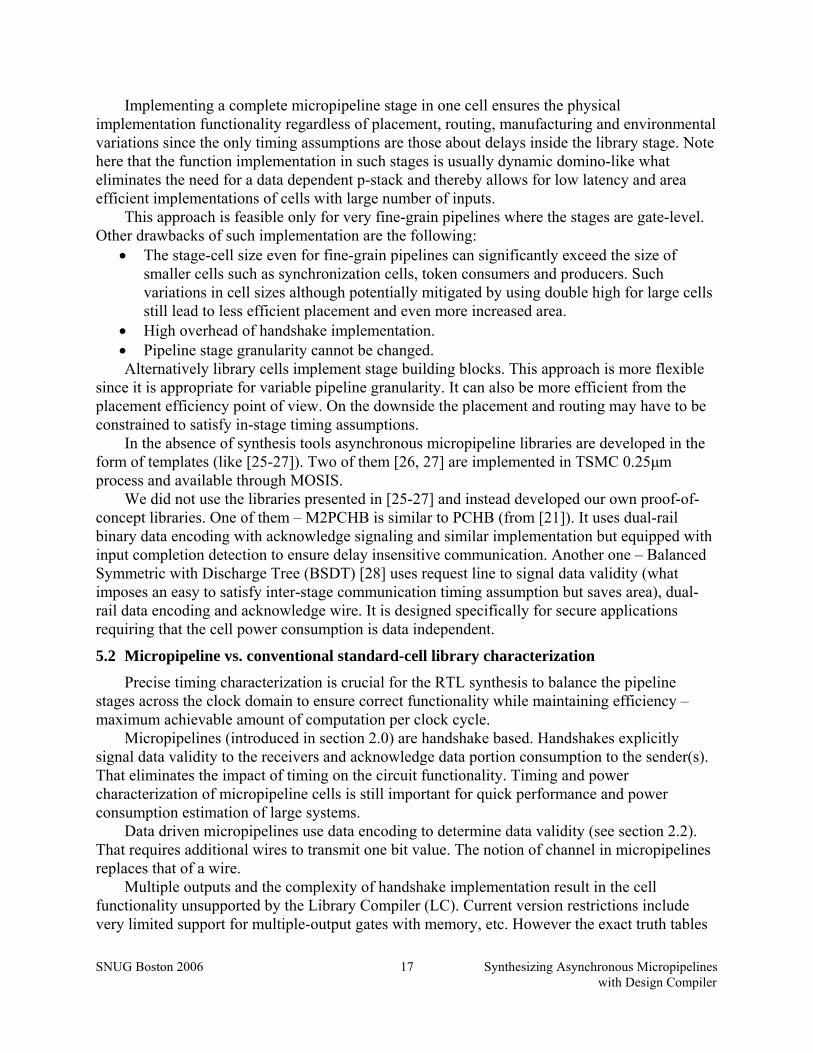
During library installation the cell and stage libraries are analyzed and validated for syntax, required set of cells and consistency by the Weaver engine. If the libraries are valid two more libraries (with Liberty characterization and VHDL specification) are generated: complete stage library and virtual library.
Stage characterization
(Liberty)
Cell characterization
(Liberty)
Cell functionality (VHDL)
Stage functionality (VHDL)
Stage library Cell library
Library validation and pre-synthesizing missing modules (Weaver engine)
Complete stage characterization
(Liberty)
Complete stage functionality
(VHDL)
Complete stage library
Virtual library characterization
(Liberty)
Virtual library functionality
(VHDL)
Virtual library
Pre-compilation (Synopsys Library Compiler, Weaver engine)
Figure 12 Simplified Weaver flow library structure
Complete stage library is the stage library complete with missing modules that can be generated automatically such as inverter (can be generated for dual-rail one-hot encoded libraries), token source, token sink, etc.
An effort is under way to support variable granularity asynchronous pipelining. This requires dynamically synthesizing stages out of simpler building blocks. When complete it will eliminate the need for the stage library required for the current version of our tool.
Virtual library (VL) is a single-rail conventional library functionally equivalent to the stage library (see Figure 5 and Figure 7 for examples of VL cells and corresponding micropipeline library stages). In addition to combinational gates it contains d-latch and d-flip-flop to prevent the Design Compiler from generating state-holding gates out of combinational logic. Characterization of the micropipeline stages is transferred to the VL cells wherever possible to render optimizations correct and estimations close to the final result. There are currently two approaches for fan-out/load characterization in the VL. One approach is to copy the data wires fan-out/load characterization from the cell library and let Design Compiler optimize it during the synthesis step. This approach may lead to replicating logical structures later mapped to resulting in replicating micropipeline structures and therefore unnecessary area overhead. By default fan-outs of the gates in VL are set to very large values to prevent any replication or buffering during RTL synthesis. VHDL specification of the VL cells is generated using Synopsys Library Compiler using VITAL package. Note that the VL does not contain any tri-state logic. This is one of the current limitations of the flow. Specifications requiring tri-state logic currently cannot be re-implemented. They must be re-written to use multiplexers. Alternatively CHAINworks from Silistix can be used to generate complex interconnect.
Lastly the virtual, complete stage and cell libraries are pre-compiled with Synopsys Library Compiler, Design Compiler and Weaver Engine.
SNUG Boston 2006 Synthesizing Asynchronous Micropipelines with Design Compiler
22
6.0 Weaver synthesis flow Weaver design flow exploits architectural similarity of micropipeline and synchronous RTL
implementations of the same design. It uses Synopsys Design Compiler as a front-end facing design specification, synthesis core and as the final netlist front-end. This allows for support for synthesizable HDL as it is defined for Synopsys Design Compiler and seamless interface with the tools following synthesis in the design flow. Micropipeline architecture mimics the initial RTL architecture and Synopsys DC acts as a familiar highly customizable front-end that allows the designer to architect the implementation further re-implemented as a micropipeline.
Re-implementation engine we called Weaver engine (WE) implements primarily re-implementation and library preparation functionality. WE is written in C++ and uses SAVANT [31] VHDL analyzer maintained by Clifton Labs for interfacing with VHDL specifications and Synopsys Liberty Parser to interface with library specifications in Synopsys Liberty format.
A set of Tcl scripts implements interoperation of the Weaver engine with Design Compiler and other tools thereby automating the entire flow as described in section 6.2.
6.1 Synthesis flow
Figure 13 presents the basic micropipeline synthesis flow. The specification front-end and final netlist front-end processes shown are executed using the Synopsys Design Compiler. Its three major steps are described in the following sections 6.1.1, 6.1.2 and 6.1.3.
Our design flow supports hierarchical designs through Synopsys Automated Chip Synthesis. The implementation architecture is defined during RTL synthesis and achieved through customizing and if necessary iterating the ACS runs. Once the desired architecture is synthesized the synthesis can proceed. Minor architectural changes can be made during re-implementation. Re-implementation is currently bottom-up since every submodule needs to be characterized as a micropipeline module. WE uses Liberty format with micropipeline extensions (described in section 5.3) to communicate the module characterization for use during re-implementation of higher level hierarchical modules. 6.1.1 RTL synthesis
RTL implementation is synthesized with Synopsys Design Compiler from a specification in a synthesizable HDL using virtual library. RTL synthesis step defines the design architecture. It can be customized as if a synchronous implementation was the target. VITAL functionality specifications of the VL cells can be used to simulate this intermediate implementation.
When architecting design for micropipeline implementation the designer should follow the following guidelines. • Micropipeline performance is limited by the maximum latency through a loop divided by the
number of tokens in the loop. If the design has no loops its performance is defined by the library implementation (the only loops are those formed by the acknowledgement lines) and slack matching (explained in section 6.1.2). Implementation loops thus must be either shortened (to decrease the latency through the loop) or pipelined if possible (to increase the number of tokens in the loop). In an effort to shorten the loops for example FSMs can be synthesized using one-hot encoding.
• If gate-level micropipeline is the target implementation (currently Weaver does not implement variable degree pipelining) most of the registers will be optimized out therefore specifying different clock periods is likely to produce the same result.

SNUG Boston 2006 Synthesizing Asynchronous Micropipelines with Design Compiler
23
Syn
opsy
s D
esig
n C
ompi
ler
RTL synthesis
Re-implementation(Weaver engine)
Fan-out/load optimization, ungrouping
Final micropipeline netlist
Stage library
Virtual library
Cell library
Synchronous netlist (VHDL)
Synchronous netlist (VHDL)
Synchronous netlist (VHDL)
Synthesizable design
specification
Synthesizable design
specification
Synthesizable design
specification
Synchronous netlist (VHDL)
Synchronous netlist (VHDL)
Micropipeline netlist (VHDL)
place & route etc tools following synthesis in EDA flow
Figure 13 Design flow using Weaver
6.1.2 Re-implementation The theory behind re-implementation is partly presented in [12, 23] and briefly in section
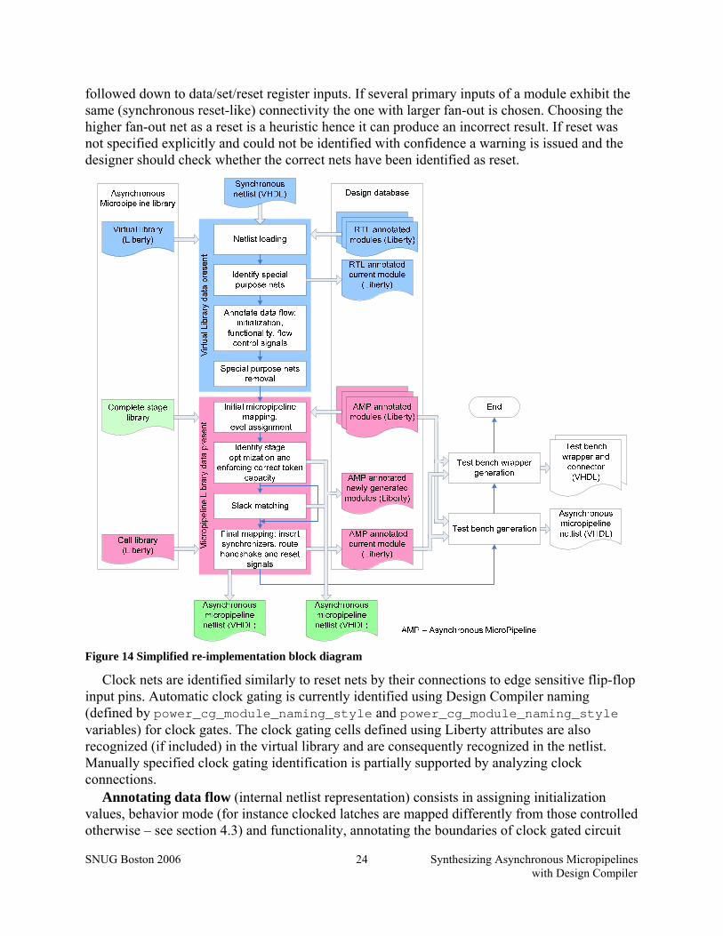
4.0 of this paper. In practice re-implementation follows the steps shown on the Figure 14. Netlist loading consists in reading and initial elaboration of the VHDL netlist. Instantiated
cells are matched against the previously loaded virtual library and the set of Liberty files (available from the design database) with reset, clock, clock gates and etc nets annotated. Re-implementation cannot proceed unless all lower level modules have been identified.
Special purpose nets identified on the following step currently include reset, clock and clock gating control signals. These signals are not mapped to channels but used for determining initial state, behavior of state holding elements as well as the signals controlling the data flow (clock gating control). Active “1” and/or active “0” reset signals as well as clocks can be specified by user (currently through configuration file). If not specified explicitly the special nets can be identified automatically.
In synchronous netlist asynchronously resettable registers feature set and/or clear input pins connected to the reset net. Synchronous reset sets the register input data to the reset value and the register gets reset at the next clock cycle. Reset architectures determine the reset nets identification. First the nets connected to asynchronous set/reset register inputs are tracked down to the module interface and annotated as reset. With no registers with asynchronous reset pins (synchronous reset only) and when reset name is not specified explicitly (by the designer) reset nets are identified as input net(s) connected directly or through buffers and/or inverters and user defined number (usually one) levels of logic to register data inputs. Once identified reset nets are
SNUG Boston 2006 Synthesizing Asynchronous Micropipelines with Design Compiler
24
followed down to data/set/reset register inputs. If several primary inputs of a module exhibit the same (synchronous reset-like) connectivity the one with larger fan-out is chosen. Choosing the higher fan-out net as a reset is a heuristic hence it can produce an incorrect result. If reset was not specified explicitly and could not be identified with confidence a warning is issued and the designer should check whether the correct nets have been identified as reset.
Figure 14 Simplified re-implementation block diagram
Clock nets are identified similarly to reset nets by their connections to edge sensitive flip-flop input pins. Automatic clock gating is currently identified using Design Compiler naming (defined by power_cg_module_naming_style and power_cg_module_naming_style variables) for clock gates. The clock gating cells defined using Liberty attributes are also recognized (if included) in the virtual library and are consequently recognized in the netlist. Manually specified clock gating identification is partially supported by analyzing clock connections.
Annotating data flow (internal netlist representation) consists in assigning initialization values, behavior mode (for instance clocked latches are mapped differently from those controlled otherwise – see section 4.3) and functionality, annotating the boundaries of clock gated circuit

SNUG Boston 2006 Synthesizing Asynchronous Micropipelines with Design Compiler
25
domain and the corresponding control channels. Functionality annotation simplifies the logic used in synchronous resetting eliminating the reset input(s). Token generators and consumers are inferred for the signals connected to VDD or ground and those left open respectively.
Special nets removal is done after annotation to leave the annotated nodes interconnected by data channels only. The special nets’ buffering, original clock gates and other logic associated with special nets and not needed for data computations are also removed.
Initial micropipeline mapping consists in identifying micropipeline stages/submoules to implement nodes of the circuit. It is necessary for level assignment used later on for slack matching and checking the minimum token capacity of closed loops.
The library of available micropipeline stages and micropipeline annotated specifications of lower level submodules are needed on this step to determine the lengths of the dependencies inside the modules. A simple level assignment example is presented on the Figure 15.
Figure 15b shows simplified internal representation of a module shown on the Figure 15a. Internally wires and functional dependencies between module pins (aka timing arcs) are annotated with their length in the number of HB stages (shown as numbers on arcs). Numbers at the connection points show the levels of those connection points.
Figure 15 Level assignment and module annotation example: two independent adders grouped into a hierarchical module
Leveling implementation is based on topological sort executed from each of the token sources stages initialized to a data token, token generators and primary inputs. The algorithm is progress driven to make the overall complexity lower than the upper bound (|V|+|E|)*|nts|, where nts is the number of token sources (primary inputs, toucan sources and stages initialized with data tokens), |V| is the number of connection points and |E| number of dependencies between connection points. The first component is coming from the Θ(|V|+|E|) complexity of the single source depth first search based topological sort algorithm.
The algorithm is assigning the smallest levels possible to the primary outputs and the largest possible to the primary inputs. This can potentially reduce the critical path length and therefore the implementation latency and area. The dependencies inside submodules (or gates) are treated as non-stretchable. Therefore if one of the inputs of an AND2 gate is found to be on the level 2 its output is assigned the level 3 and the other input – level 2.
Once the levels are computed the lengths of dependencies can be annotated for the modules it is shown on the Figure 15c. Note that when the higher level module (for which our module
SNUG Boston 2006 Synthesizing Asynchronous Micropipelines with Design Compiler
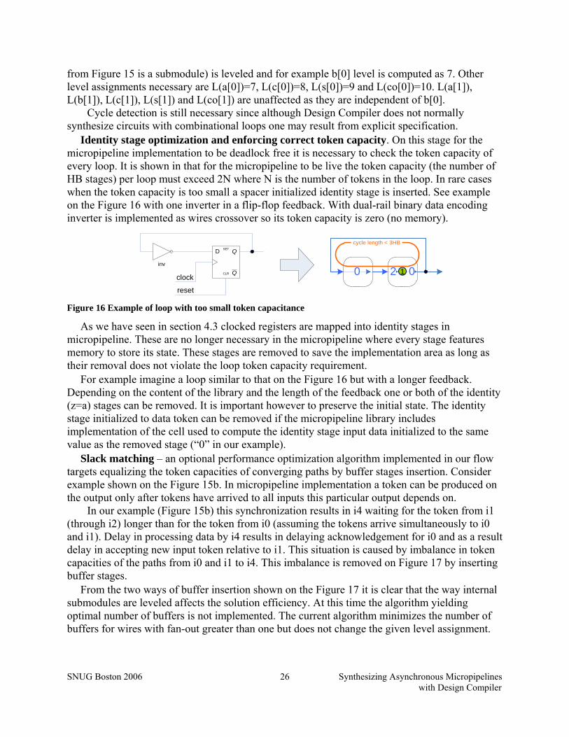
26
from Figure 15 is a submodule) is leveled and for example b[0] level is computed as 7. Other level assignments necessary are L(a[0])=7, L(c[0])=8, L(s[0])=9 and L(co[0])=10. L(a[1]), L(b[1]), L(c[1]), L(s[1]) and L(co[1]) are unaffected as they are independent of b[0].
Cycle detection is still necessary since although Design Compiler does not normally synthesize circuits with combinational loops one may result from explicit specification.
Identity stage optimization and enforcing correct token capacity. On this stage for the micropipeline implementation to be deadlock free it is necessary to check the token capacity of every loop. It is shown in that for the micropipeline to be live the token capacity (the number of HB stages) per loop must exceed 2N where N is the number of tokens in the loop. In rare cases when the token capacity is too small a spacer initialized identity stage is inserted. See example on the Figure 16 with one inverter in a flip-flop feedback. With dual-rail binary data encoding inverter is implemented as wires crossover so its token capacity is zero (no memory).
0 2 01Q
QSET
CLR
D
inv
clock
reset
cycle length < 3HB
Figure 16 Example of loop with too small token capacitance
As we have seen in section 4.3 clocked registers are mapped into identity stages in micropipeline. These are no longer necessary in the micropipeline where every stage features memory to store its state. These stages are removed to save the implementation area as long as their removal does not violate the loop token capacity requirement.
For example imagine a loop similar to that on the Figure 16 but with a longer feedback. Depending on the content of the library and the length of the feedback one or both of the identity (z=a) stages can be removed. It is important however to preserve the initial state. The identity stage initialized to data token can be removed if the micropipeline library includes implementation of the cell used to compute the identity stage input data initialized to the same value as the removed stage (“0” in our example).
Slack matching – an optional performance optimization algorithm implemented in our flow targets equalizing the token capacities of converging paths by buffer stages insertion. Consider example shown on the Figure 15b. In micropipeline implementation a token can be produced on the output only after tokens have arrived to all inputs this particular output depends on.
In our example (Figure 15b) this synchronization results in i4 waiting for the token from i1 (through i2) longer than for the token from i0 (assuming the tokens arrive simultaneously to i0 and i1). Delay in processing data by i4 results in delaying acknowledgement for i0 and as a result delay in accepting new input token relative to i1. This situation is caused by imbalance in token capacities of the paths from i0 and i1 to i4. This imbalance is removed on Figure 17 by inserting buffer stages.
From the two ways of buffer insertion shown on the Figure 17 it is clear that the way internal submodules are leveled affects the solution efficiency. At this time the algorithm yielding optimal number of buffers is not implemented. The current algorithm minimizes the number of buffers for wires with fan-out greater than one but does not change the given level assignment.

SNUG Boston 2006 Synthesizing Asynchronous Micropipelines with Design Compiler
27
11
11
11
11
0
00
11
0
1 00
0
1
1
12
2
32 2
1
1
1
1
1
2
11
11
11
11
0
00
11
0
00
0
1
1
12
2
3
22
1
1
1
1
1
21
1
011i0
i1
i2
i3
i4
i0
i1
i2
i3
i4
b0
b1
b0
Figure 17 Slack matching of the adder circuit
Micropipeline mapping consists in synthesizing the micropipeline implementation from the dataflow-like internal representation using the cells available in the library and annotated micropipeline versions of the lower level modules found in the design database. Mapping involves choosing appropriate modules, inserting appropriate synchronization cells, connecting data, handshake and reset signals.
Muller C-elements are often used as synchronization cells. These are state holding elements. Resettable synchronization cells are usually slightly more expensive (area-wise) than cells without synchronization. At the same time resettable synchronization cells are only necessary where initial values of its inputs differ. WE analyze initial values of the synchronized signals and inserts synchronizers without reset input wherever possible.
Test bench generation is optional. For micropipeline input data must be alternated with spacers and the handshake signals must conform to the implemented protocol. That makes writing a test bench tedious. The automatically generated VHDL test bench consists of a set of token generators and token consumers independent of each other. This test bench is primarily intended for verifying the implementation deadlock freedom, cycle time and overall implementation dynamics. Simple functionality checks can be performed as well.
Test bench wrapper generation is also optional and produces two VHDL entities that convert asynchronous interface of the micropipeline implementation into synchronous clocked interface thus allowing using the legacy test bench created for synchronous implementation as it is shown on the Figure 18. This wrapper consists of a set of data generators that every clock cycle feed the data received from the test bench to the micropipeline implementation performing the data encoding and generating the necessary handshake signals. The test bench wrapper observes the acknowledgement signals (if supported by the protocol) to determine if all data has been consumed by the implementation before the next clock cycle. If the micropipeline implementation is unable to keep up with the clock provided by the synchronous test bench an assertion fails requesting lowering the clock frequency and restarting the simulation.
Asynchronous micropipeline
implementation (VHDL)
Test bench wrapper (VHDL)
Synchronous test bench (VHDL)
Connecting entity (VHDL)
Figure 18 Simulating asynchronous micropipeline implementation with legacy VHDL test bench
SNUG Boston 2006 Synthesizing Asynchronous Micropipelines with Design Compiler
28
The data receivers synchronize output data i.e. bits of a bus are only given to the test bench as the circuit output as soon as all the bits are received. Upon receipt of all bits they are acknowledged to the implementation. Synchronization is necessary for the synchronous test bench and simplifies observing the output data. Without synchronization depending on the implementation the bits may be significantly skewed relative to each other. In such case synchronization may slow down the implementation by creating congestion on the output bits that appear before others. That makes the test bench wrapper best suited for functionality verification and not for checking its dynamics. 6.1.3 Fan-out/load optimization, ungrouping
Design compiler is used on this stage as a final netlist front-end to: • analyze fan-out/load and buffer insufficiently strong nets with conventional single-rail
binary buffers and/or inverters; • optionally ungroup user defined compound stages and other modules found in the stage
library and the modules generated on the fly to ensure that the final netlist is mapped to the cells found in technology library;
• translate the final netlist to formats other than VHDL; No optimization (except for fan-out/load) is performed on this stage. This is ensured by
specifying technology library cells as “black boxes”. If the library has been characterized it contains timing arcs which due to the nature of handshaking introduce lots of timing loops. These timing arcs are disabled to prevent Design Compiler from needlessly detecting and breaking all the timing loops during constraints generation.
6.2 Extending the Design Compiler
We chose to implement micropipeline synthesis by including new commands implemented as Synopsys Tcl procedures in the Design Compiler interface. It is done using define_proc_attributes to specify a set of options used with the newly included procedures as well as brief information on their usage available from under the DC shell. Weaver commands are included in the DC interface by including (source) the initialization script usually from the configuration file .synopsys_dc.setup. Alternatively the initialization script can be included explicitly by the designer. The initialization script for m2pchb library is shown on the Figure 19. Liberty and VHDL library file locations are specified in the WE configuration file.
In order to support synthesizing hierarchical designs our synthesis flow is based on the Synopsys Automatic Chip Synthesis (ACS).
After the design has been read into memory (using acs_read_hdl) and its partitioning has been defined the acs_compile_design would normally be used to compile a synchronous implementation. Instead we defined the wvr_acs_compile_design command to compile the micropipeline implementation. wvr_acs_compile_design executes the synthesis flow presented on the Figure 13. In order to let the designer iterate on every design stage each of the design steps can be executed separately.
The commands are wvr_acs_compile_rtl, wvr_acs_reimplement and wvr_acs_compile_qdi respectively.

SNUG Boston 2006 Synthesizing Asynchronous Micropipelines with Design Compiler
29
Figure 19 Sample Weaver flow initialization script
RTL synthesis performed by the wvr_acs_compile_rtl is almost identical to acs_compile_design. Since only VHDL can be used to communicate with WE (re-implementation engine) VHDL code is generated for every synthesized synchronous netlists and saved in a temporary directory. Although the design hierarchy could be determined by the WE, currently re-implementation is performed in the order in which ACS compiled the designs during this step. It is crucial for re-implementation that the library used for synthesis on this step is the virtual library generated during the library installation (as described in section 5.4). Hence the target and link library are set automatically. These and some other DC global variables should not be customized by the designer (are overwritten).
The above functionality is implemented in wvr_compile_rtl that calls compile and performs the above operations. The wvr_acs_compile_rtl separates generating the constraints and script files from compilation itself and modifies automatically generated compile scripts in between to substitute the compile by the wvr_acs_compile_rtl and set the necessary variables (ACS scripts are executed with gmake and the current global variables are not available for the scripts). Such implementation enables using ACS commands for hierarchical designs and reusing with little changes the scripts written for DC and using the compile command.
Re-implementation is performed by WE called from under wvr_acs_reimplement for every netlist in hierarchy. WE saves the re-implemented netlists and the netlists for modules generated during the re-implementation (for example chains of buffer stages inserted during slack matching). Weaver engine is customized through a separate configuration file named .weaver_engine.setup located in the design directory and through the command line options. Command line options have priority. Actual configurable parameters are recorded to .weaver_engine.setup.out that can be used to reproduce the last run.
############################################################################### ###### specify the names of micropipeline cells library files ###### ############################################################################### ## VHDL library name set base_lib_name "m2pchb" ## stage library name set stage_lib_name "m2pchb4wvr" ## technology library name set cell_lib_name "m2pchb4pr" ###### specify the list of VHDL packages to be included in the final netlist set vhdlout_use_packages [list ieee.std_logic_1164.all m2pchb.m2pchb4pr.all \ m2pchb.m2pchb4wvr.all m2pchb.m2pchb4wvr_warc.all weaver.wvr_definitions.all \ m2pchb.vcomponents.all ] ############################################################################### # DO NOT EDIT THE FOLLOWING CODE USED TO INITIALIZE THE WEAVER-DC ENVIRONMENT # ############################################################################### set weaver_home [getenv WEAVER_FLOW] if { $weaver_home == {} } { echo "\nError:\tWEAVER_FLOW environment variable is not set. It MUST specify" echo "\tthe directory containing the Weaver-DC synthesis flow installation." echo "\nDefine WEAVER_FLOW environment variable and try again." quit } ###### initialize the Weaver-DC environment source [format %s%s $weaver_home "/scr/weaver_init.tcl"] ###############################################################################
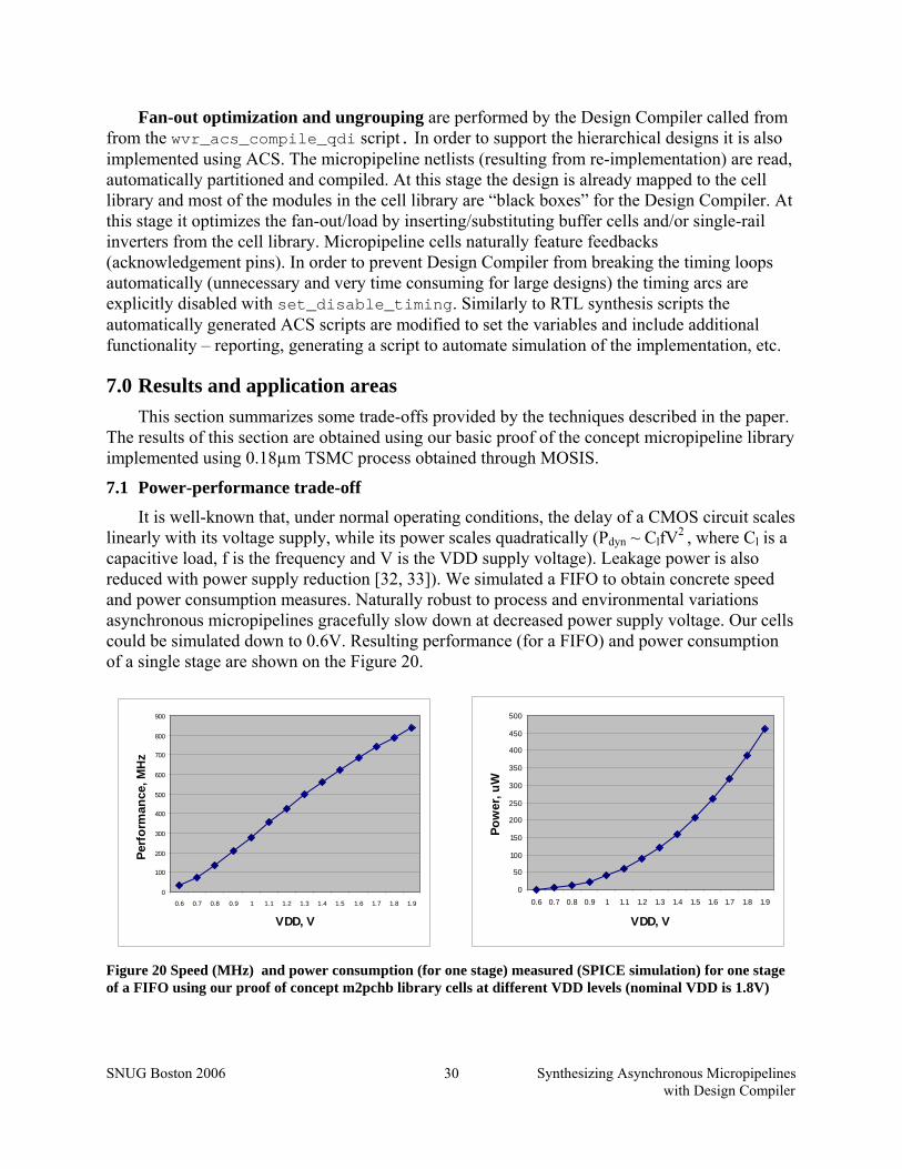
SNUG Boston 2006 Synthesizing Asynchronous Micropipelines with Design Compiler
30
Fan-out optimization and ungrouping are performed by the Design Compiler called from from the wvr_acs_compile_qdi script. In order to support the hierarchical designs it is also implemented using ACS. The micropipeline netlists (resulting from re-implementation) are read, automatically partitioned and compiled. At this stage the design is already mapped to the cell library and most of the modules in the cell library are “black boxes” for the Design Compiler. At this stage it optimizes the fan-out/load by inserting/substituting buffer cells and/or single-rail inverters from the cell library. Micropipeline cells naturally feature feedbacks (acknowledgement pins). In order to prevent Design Compiler from breaking the timing loops automatically (unnecessary and very time consuming for large designs) the timing arcs are explicitly disabled with set_disable_timing. Similarly to RTL synthesis scripts the automatically generated ACS scripts are modified to set the variables and include additional functionality – reporting, generating a script to automate simulation of the implementation, etc.
7.0 Results and application areas This section summarizes some trade-offs provided by the techniques described in the paper.
The results of this section are obtained using our basic proof of the concept micropipeline library implemented using 0.18µm TSMC process obtained through MOSIS.
7.1 Power-performance trade-off
It is well-known that, under normal operating conditions, the delay of a CMOS circuit scales linearly with its voltage supply, while its power scales quadratically (Pdyn ~ ClfV2 , where Cl is a capacitive load, f is the frequency and V is the VDD supply voltage). Leakage power is also reduced with power supply reduction [32, 33]). We simulated a FIFO to obtain concrete speed and power consumption measures. Naturally robust to process and environmental variations asynchronous micropipelines gracefully slow down at decreased power supply voltage. Our cells could be simulated down to 0.6V. Resulting performance (for a FIFO) and power consumption of a single stage are shown on the Figure 20.
0
100
200
300
400
500
600
700
800
900
0.6 0.7 0.8 0.9 1 1.1 1.2 1.3 1.4 1.5 1.6 1.7 1.8 1.9
VDD, V
Perf
orm
ance
, MH
z
0
50
100
150
200
250
300
350
400
450
500
0.6 0.7 0.8 0.9 1 1.1 1.2 1.3 1.4 1.5 1.6 1.7 1.8 1.9
VDD, V
Pow
er, u
W
Figure 20 Speed (MHz) and power consumption (for one stage) measured (SPICE simulation) for one stage of a FIFO using our proof of concept m2pchb library cells at different VDD levels (nominal VDD is 1.8V)
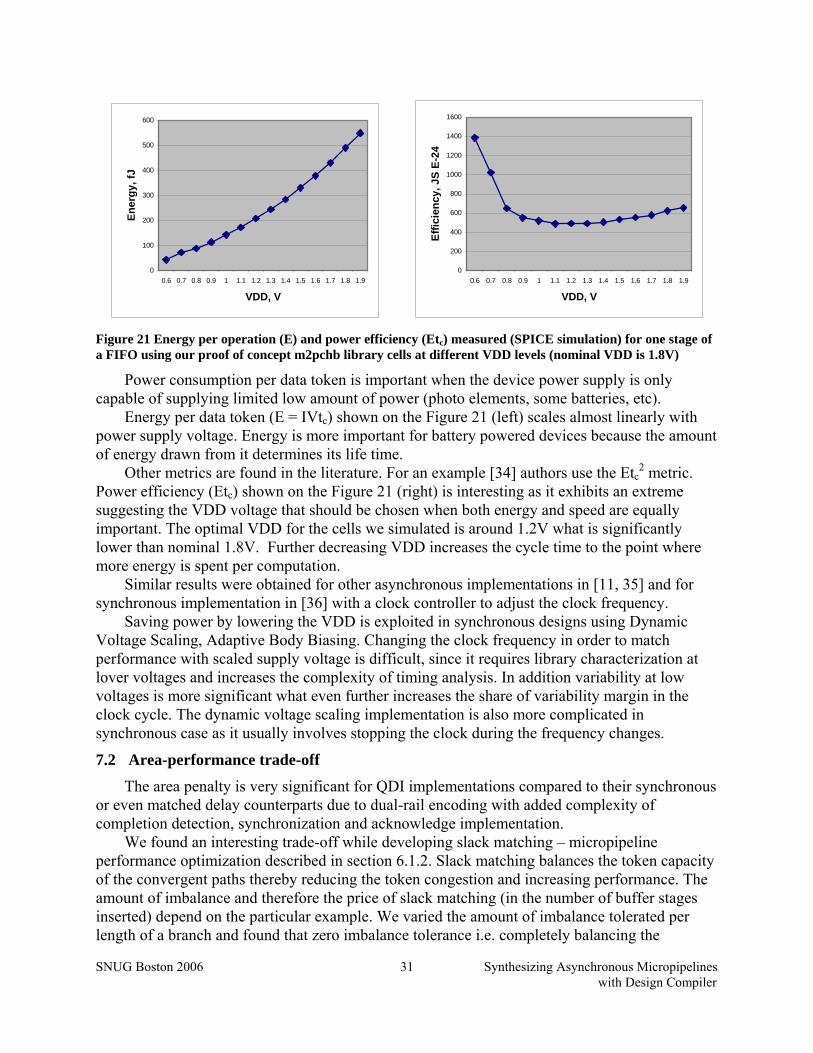
SNUG Boston 2006 Synthesizing Asynchronous Micropipelines with Design Compiler
31
0
100
200
300
400
500
600
0.6 0.7 0.8 0.9 1 1.1 1.2 1.3 1.4 1.5 1.6 1.7 1.8 1.9
VDD, V
Ener
gy, f
J
0
200
400
600
800
1000
1200
1400
1600
0.6 0.7 0.8 0.9 1 1.1 1.2 1.3 1.4 1.5 1.6 1.7 1.8 1.9
VDD, V
Effic
ienc
y, J
S E-
24
Figure 21 Energy per operation (E) and power efficiency (Etc) measured (SPICE simulation) for one stage of a FIFO using our proof of concept m2pchb library cells at different VDD levels (nominal VDD is 1.8V)
Power consumption per data token is important when the device power supply is only capable of supplying limited low amount of power (photo elements, some batteries, etc).
Energy per data token (E = IVtc) shown on the Figure 21 (left) scales almost linearly with power supply voltage. Energy is more important for battery powered devices because the amount of energy drawn from it determines its life time.
Other metrics are found in the literature. For an example [34] authors use the Etc2 metric.
Power efficiency (Etc) shown on the Figure 21 (right) is interesting as it exhibits an extreme suggesting the VDD voltage that should be chosen when both energy and speed are equally important. The optimal VDD for the cells we simulated is around 1.2V what is significantly lower than nominal 1.8V. Further decreasing VDD increases the cycle time to the point where more energy is spent per computation.
Similar results were obtained for other asynchronous implementations in [11, 35] and for synchronous implementation in [36] with a clock controller to adjust the clock frequency.
Saving power by lowering the VDD is exploited in synchronous designs using Dynamic Voltage Scaling, Adaptive Body Biasing. Changing the clock frequency in order to match performance with scaled supply voltage is difficult, since it requires library characterization at lover voltages and increases the complexity of timing analysis. In addition variability at low voltages is more significant what even further increases the share of variability margin in the clock cycle. The dynamic voltage scaling implementation is also more complicated in synchronous case as it usually involves stopping the clock during the frequency changes.
7.2 Area-performance trade-off
The area penalty is very significant for QDI implementations compared to their synchronous or even matched delay counterparts due to dual-rail encoding with added complexity of completion detection, synchronization and acknowledge implementation.
We found an interesting trade-off while developing slack matching – micropipeline performance optimization described in section 6.1.2. Slack matching balances the token capacity of the convergent paths thereby reducing the token congestion and increasing performance. The amount of imbalance and therefore the price of slack matching (in the number of buffer stages inserted) depend on the particular example. We varied the amount of imbalance tolerated per length of a branch and found that zero imbalance tolerance i.e. completely balancing the
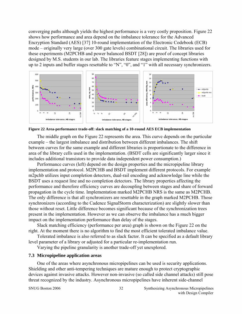
SNUG Boston 2006 Synthesizing Asynchronous Micropipelines with Design Compiler
32
converging paths although yields the highest performance is a very costly proposition. Figure 22 shows how performance and area depend on the imbalance tolerance for the Advanced Encryption Standard (AES) [37] 10-round implementation of the Electronic Codebook (ECB) mode – originally very large (over 300 gate levels) combinational circuit. The libraries used for these experiments (M2PCHB and power balanced BSDT [28]) are proof of concept libraries designed by M.S. students in our lab. The libraries feature stages implementing functions with up to 2 inputs and buffer stages resettable to “N”, “0”, and “1” with all necessary synchronizers.
Figure 22 Area-performance trade-off: slack matching of a 10-round AES ECB implementation
The middle graph on the Figure 22 represents the area. This curve depends on the particular example – the largest imbalance and distribution between different imbalances. The shift between curves for the same example and different libraries is proportionate to the difference in area of the library cells used in the implementation. (BSDT cells are significantly larger since it includes additional transistors to provide data independent power consumption.)
Performance curves (left) depend on the design properties and the micropipeline library implementation and protocol. M2PCHB and BSDT implement different protocols. For example m2pchb utilizes input completion detectors, dual-rail encoding and acknowledge line while the BSDT uses a request line and no completion detectors. The library properties affecting the performance and therefore efficiency curves are decoupling between stages and share of forward propagation in the cycle time. Implementation marked M2PCHB NRS is the same as M2PCHB. The only difference is that all synchronizers are resettable in the graph marked M2PCHB. Those synchronizers (according to the Cadence SignalStorm characterization) are slightly slower than those without reset. Little difference becomes significant because of the synchronization trees present in the implementation. However as we can observe the imbalance has a much bigger impact on the implementation performance than delay of the stages.
Slack matching efficiency (performance per area) graph is shown on the Figure 22 on the right. At the moment there is no algorithm to find the most efficient tolerated imbalance value.
Tolerated imbalance is also referred to as slack factor. It can be specified as a default library level parameter of a library or adjusted for a particular re-implementation run.
Varying the pipeline granularity is another trade-off yet unexplored.
7.3 Micropipeline application areas
One of the areas where asynchronous micropipelines can be used is security applications. Shielding and other anti-tempering techniques are mature enough to protect cryptographic devices against invasive attacks. However non-invasive (so called side channel attacks) still pose threat recognized by the industry. Asynchronous micropipelines have inherent side-channel
0
100
200
300
400
500
600
0 3 6 12 24
no S
M
imbalance tolerance, HB stages
perf
orm
ance
, MH
z
0
10
20
30
40
50
60
70
80
90
0 3 6 12 24no
SM
imbalance tolerance, HB stages
area
, sq.
mm
0
2
4
6
8
10
12
14
16
18
0 3 6 12 24
no S
M
imbalance tolerance, HB stages
area
eff
icie
ncy,
MH
z/Sq
.mm
m2pchb
m2pchb nrs
bsdt
SNUG Boston 2006 Synthesizing Asynchronous Micropipelines with Design Compiler
33
attack resistance features (robustness to glitch and timing attacks etc) that can be well combined with power balancing used to resist differential power attacks (DPA) [38, 39]. The area overhead suffered by the asynchronous fine-grain micropipelines is acceptable in this kind of applications where duplication and triplication are not uncommon.
High performance achieved with very fine-grain pipelining and low latency achieved through dynamic logic based stage implementation that can perform at its maximum possible speed unconstrained by margins based on worst case delay assumptions make micropipelines attractive for high speed applications. Fulcrum Microsystems with their family of micropipeline based products.
As we have shown in sections 4.4 and 7.1, micropipelines’ robustness to variations and on-need operation can be exploited in low-power architectures. Numerous examples of this include AMULET processors [40-43], SNAP sensor network microprocessor [44] and many others.
8.0 Acknowledgements Authors thank Omnibase Logic for partial support of this work, M.S. students Ming Su and
Daniel McDonald for developing micropipeline libraries for the flow as well as Mohamad Said for help with test bench wrapper generator implementation.
References 1. Aseem Agarwal, et al. Statistical Timing Analysis Using Bounds. in Design, Automation
and Test in Europe (DATE). 2003. 2. P. Beerel, J. Cortadella, and A. Kondratyev. Bridging the gap between asynchronous
design and designers. (Tutorial). in VLSI Design Conference. 2004. Mumbai. 3. Karl M. Fant and Scott A. Brandt, NULL Conventional Logic: A Complete and
Consistent Logic for Asynchronous Digital Circuit Synthesis, in International Conference on Application-specific Systems, Architectures, and Processors. 1996. p. 261--273.
4. Ross Smith and Michiel Ligthart. Asynchronous Logic Design with Commercial High Level Design Tools. in Synopsys Users Group. 2000. San Jose.
5. Handshake Solutions http://www.handshakesolutions.com. 6. Kees van Berkel, Handshake Circuits: an Asynchronous Architecture for VLSI
Programming. Vol. 5. 1993: Cambridge University Press. 7. Ivan E. Sutherland, Micropipelines. Communications of the ACM, 1989. 32(6): p. 720--
738. 8. David E. Muller and W. S. Bartky, A Theory of Asynchronous Circuits, in Proceedings of
an International Symposium on the Theory of Switching. 1959, Harvard University Press. p. 204--243.
9. V.I. Varshavsky, et al., Self-timed Control of Concurrent Processes. 1990: Kluwer Academic Publishers.
10. Daniel H. Linder and James C. Harden, Phased Logic: Supporting the Synchronous Design Paradigm with Delay-Insensitive Circuitry. IEEE Transactions on Computers, 1996. 45(9): p. 1031--1044.
11. I. Blunno, et al. Handshake protocols for de-synchronization. in International Symposium on Advanced Research in Asynchronous Circuits and Systems. 2004.

SNUG Boston 2006 Synthesizing Asynchronous Micropipelines with Design Compiler
34
12. A. Smirnov, A. Taubin, and M. Karpovsky. Automated Pipelining in ASIC Synthesis Methodology: Gate Transfer Level. in IWLS 2004 Thirteenth International Workshop on Logic and Synthesis. 2004.
13. Alexander Smirnov, et al. An Automated Fine-Grain Pipelining Using Domino Style Asynchronous Library. in Fifth International Conference on Application of Concurrency to System Design (ACSD). 2005. St.Malo, France: IEEE CS Press.
14. Jordi Cortadella, et al., Petrify: a tool for manipulating concurrent specifications and synthesis of asynchronous controllers, in XI Conference on Design of Integrated Circuits and Systems. 1996: Barcelona.
15. Ad Peeters and Mark de Wit, Haste Manual. 2005, Handshake Solutions. 16. C. A. R. Hoare, Communicating Sequential Processes. 1985: Prentice-Hall. 17. Alain J. Martin, Programming in VLSI: From Communicating Processes to Delay-
Insensitive Circuits, in Developments in Concurrency and Communication, C.A.R. Hoare, Editor. 1990, Addison-Wesley. p. 1--64.
18. Silistix http://www.silistix.com. 19. Michael D. Ciletti, Advanced Digital Design with the Verilog HDL. 2003, Upper Saddle
River: Pearson Education Inc. 20. Recep O. Ozdag, et al., High-Speed Non-Linear Asynchronous Pipelines, in Proc.
Design, Automation and Test in Europe (DATE). 2002. p. 1000--10007. 21. Recep O. Ozdag and Peter A. Beerel, High-Speed QDI Asynchronous Pipelines, in Proc.
International Symposium on Advanced Research in Asynchronous Circuits and Systems. 2002. p. 13--22.
22. Power Compiler User Guide, in Synopsys On-Line Documentation. 23. Alexander Smirnov, et al. Gate Transfer Level Synthesis as an Automated Approach to
Fine-Grain Pipelining. in Workshop on Token Based Computing (ToBaCo). 2004. Bologna, Italy.
24. P. L. Guernic, J.-P. Talpin, and J.-C. L. Lann, Polychrony for system design. Journal of Circuits, Systems and Computers, 2003.
25. Sunan Tugsinavisut and Peter A. Beerel, Control Circuit Templates for Asynchronous Bundled-Data Pipelines, in Proc. Design, Automation and Test in Europe (DATE). 2002. p. 1098.
26. Marcos Ferretti and Peter A. Beerel, Single-Track Asynchronous Pipeline Templates Using 1-of-N Encoding, in Proc. Design, Automation and Test in Europe (DATE). 2002. p. 1008--1015.
27. Recep O. Ozdag and Peter A. Beerel. A Channel Based Asynchronous Low Power High Performance Standard-Cell Based Sequential Decoder Implementated with QDI Templates. in International Symposium on Advanced Research in Asynchronous Circuits and Systems. 2004.
28. Daniel Jay MacDonald, MS Thesis. A Balanced-Power Domino-Style Standard Cell Library for Fine-Grain Asynchronous Pipelined Design to Resist Differential Power Analysis Attacks, in Department of Electrical and Computer Engeneering. 2005, Boston University: Boston. p. 121.
29. Alexander Smirnov, Weaver library specification guide: Configuration and Extensions of the Synopsys Liberty Format. 2006, Boston University: Boston.
30. Synopsys, Liberty™ User Guide.
SNUG Boston 2006 Synthesizing Asynchronous Micropipelines with Design Compiler
35
31. D. E. Martin, et al., Analysis and Simulation of Mixed-Technology VLSI Systems. Journal of Parallel and Distributed Computing, 2002. 62(3): p. 468-493.
32. NS Kim, et al., Leakage Current: Moore's Law Meets Static Power. IEEE Comp. Society Magazine, 2003. 36(12): p. 68-75.
33. W Elgharbawy and M Bayoumi, Leakage Sources and Possible Solutions in Nanometer CMOS Technologies. IEEE Circuits and Systems Magazine, 2005. 5(4).
34. A. J. Martin, et al., The Design of an Asynchronous MIPS R3000 Microprocessor. Proceedings of Advanced Research in VLSI, 1997: p. 164-181.
35. Luca Necchi, et al. An ultra-low energy asynchronous processor for Wireless Sensor Networks. in ASYNC. 2006.
36. Noureddine Chabini, et al., Methods for Minimizing Dynamic Power Consumption in Synchronous Designs with Multiple Supply Voltages. IEEE Transactions on Computer-Aided Design of Integrated Circuits and Systems, 2003. 22(3).
37. FIPS PUB 197: Advanced Encryption Standard, http://csrc.nist.gov/publications/fips/fips197/fips-197.pdf.
38. Konrad Kulikowski, Alexander Smirnov, and Alexander Taubin. Automated Design of Cryptographic Devices resistant to Multiple Side-Channel Attacks (CHES). in Workshop on Cryptographic Hardware and Embedded Systems. 2006. Yokohama, Japan.
39. Konrad Kulikowski, et al. Delay Insensitive Encoding and Power Analysis: A Balancing Act. in International Symposium on Advanced Research in Asynchronous Circuits and Systems. 2005. New York: IEEE.
40. Stephen B. Furber, et al., AMULET2e: An Asynchronous Embedded Controller. Proceedings of the IEEE, 1999. 87(2): p. 243--256.
41. S. B. Furber, et al., AMULET1: A micropipelined ARM, in Proceedings IEEE Computer Conference (COMPCON). 1994. p. 476--485.
42. J. D. Garside, et al., AMULET3i --- an Asynchronous System-on-Chip, in Proc. International Symposium on Advanced Research in Asynchronous Circuits and Systems. 2000, IEEE Computer Society Press. p. 162--175.
43. S. B. Furber, D. A. Edwards, and J. D. Garside, AMULET3: a 100 MIPS Asynchronous Embedded Processor, in Proc. International Conf. Computer Design (ICCD). 2000.
44. C. Kelly IV, V. Ekanayake, and R. Manohar. SNAP: A Sensor Network Asynchronous Processor. in 9th International Symposium on Asynchronous Circuits and Systems. 2003. Vancouver, BC.