synthesis of symmetrical and anisotropic core-shell...
TRANSCRIPT
Synthesis of Symmetrical and Anisotropic Core-Shell Magnetic Composite Particles
and Progress in Controllable Migration of Magnetic Core in Composite Particles
by
Pingsan Song
Bachelor of Science, Nanjing University, 2007
Submitted to the Graduate Faculty of
School of Arts and Sciences in partial fulfillment
of the requirements for the degree of
Master of Science
University of Pittsburgh
2010
ii
UNIVERSITY OF PITTSBURGH
SCHOOL OF ARTS AND SCIENCES
This thesis was presented
by
Pingsan Song
It was defended on
April 12, 2010
and approved by
Nathaniel Rosi, Assistant Professor, Department of Chemistry
Alexander Star, Assistant Professor, Department of Chemistry
Thesis Director: Sanford Asher, Distinguished Professor, Department of Chemistry

iii
Copyright © by Pingsan Song
2010
iv
In this work, a two-step method is developed to synthesize both symmetrical and anisotropic
magnetic composite particles. First of all, magnetic-polymer seed particles are synthesized from
iron oxide, styrene and methyl methacrylate by emulsion polymerization. Then magnetic
composite particles are produced from synthesized seeds and styrene by seeded dispersion
polymerization. The anisotropy of the magnetic composite particles could be achieved by the
addition of a small amount of tetrahydrofuran (THF) into the alcohol-based polymerization
medium. Moreover, two solvent compositions were found to be effective to swell the synthesized
magnetic composite particles and enable the migration of magnetic cores inside the polymer
spheres. The structure of magnetic core or the morphology and monodispersity of the composite
particles were not destroyed during this swelling process. One mixture solvent contains THF,
ethylene glycol (ETG), ethanol and water, with particles protected by a suitable amount of poly
vinyl pyrrolidone-40 (PVP-40), and the other is a mixture of ETG and THF.
Synthesis of Symmetrical and Anisotropic Core-Shell Magnetic Composite Particles
and Progress in Controllable Migration of Magnetic Core in Composite Particles
Pingsan Song, M.S.
University of Pittsburgh, 2010
v
TABLE OF CONTENTS
PREFACE .................................................................................................................................... XI
1.0 INTRODUCTION TO POLYMER AND POLYMERIZATION ........................... 1
1.1 OVERVIEW OF RADICAL POLYMERIZATION ............................................... 2
1.2 EMULSION POLYMERIZATION .......................................................................... 4
1.3 DISPERSION POLYMERIZATION ........................................................................ 5
1.4 SEEDED POLYMERIZATION ................................................................................ 6
1.5 THETA STATE AND POLYMER SWELLING ..................................................... 7
2.0 INTRODUCTION TO MAGNETISM .................................................................... 10
2.1 FERROMAGNETISM, FERRIMAGNETISM AND
ANTIFERROMAGNETISM ............................................................................................. 10
2.2 SUPERPARAMAGNETISM ................................................................................... 12
3.0 CHAPTER 3: SYNTHESIS OF CORE-SHELL COMPOSITE MAGNETIC
PARTICLES AND CONTROLLABLE MIGRATION OF MAGNETIC CORE ............... 13
3.1 MOTIVATION .......................................................................................................... 13
3.2 EXPERIMENTAL METHODS ............................................................................... 14
3.2.1 Materials: ........................................................................................................ 14
3.2.2 Equipments: .................................................................................................... 14
3.2.3 Synthesis of iron oxide magnetic nanoparticles: .......................................... 15
vi
3.2.4 Synthesis of magnetic composite seed particles: .......................................... 15
3.2.5 Synthesis of symmetrical and anisotropic core-shell magnetic composite
particles: ...................................................................................................................... 16
3.2.6 Migration of magnetic core in core-shell magnetic composite particles: .. 17
3.2.7 Structure analysis of particles: ...................................................................... 18
3.3 RESULTS AND DISCUSSION ................................................................................ 18
3.3.1 Synthesis of iron oxide magnetic nanoparticles ........................................... 18
3.3.2 Synthesis of magnetic composite seed particles ........................................... 19
3.3.3 Synthesis of symmetrical and anisotropic core-shell magnetic composite
particles ....................................................................................................................... 20
3.3.4 Swelling of symmetrical core-shell magnetic composite particles .............. 24
3.4 CONCLUSIONS ........................................................................................................ 38
BIBLIOGRAPHY ....................................................................................................................... 40
vii
LIST OF TABLES
Table 1. Composition of solvents used in dispersion polymerization of core-shell magnetic
particle synthesis and corresponding particle morphologies ........................................................ 21
Table 2. Particles swollen by solvents similar to dispersion polymerization media .................... 31
viii
LIST OF FIGURES
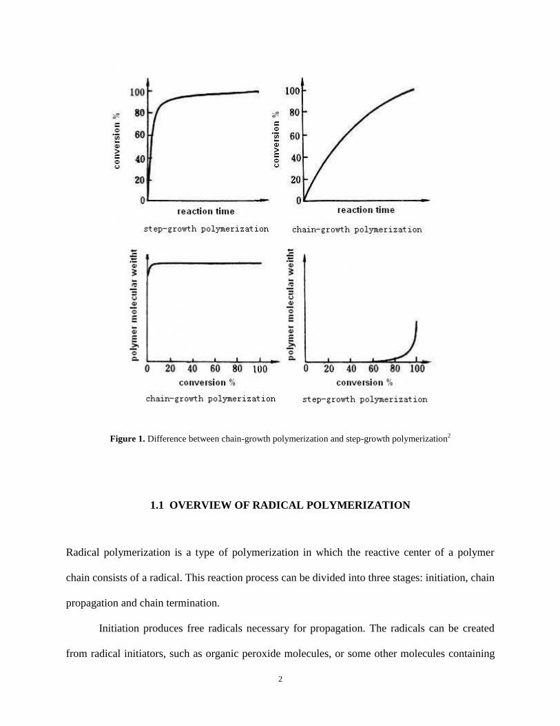
Figure 1. Difference between chain-growth polymerization and step-growth polymerization2 .... 2
Figure 2. Dissociation reaction of APS .......................................................................................... 3
Figure 3. Dissociation reaction of AIBN ....................................................................................... 4
Figure 4. Structure of Brij-35 ......................................................................................................... 5
Figure 5. Structure of poly (vinyl pyrrolidone).............................................................................. 6
Figure 6. Illustration of ferromagnetism, ferrimagnetism and antiferromagnetism .................... 11
Figure 7. Transmission electron microscopy measurement of nanoscale iron oxide .................. 19
Figure 8. Transmission electron microscopy measurement of magnetic composite seed particles
at different magnifications (left: low magnification; right: high magnification) .......................... 20
Figure 9. Transmission electron microscopy measurement of symmetrical core-shell magnetic
composite particles pis-0729009 at different magnifications (upper left: low magnification; upper
right: medium magnification, bottom, high magnification to show magnetic core) .................... 21
Figure 10. Transmission electron microscopy measurement of anisotropic core-shell magnetic
composite particles pis-080709 at different magnifications (left: low magnification; right: high
magnification) ............................................................................................................................... 22
ix
Figure 11. Transmission electron microscopy measurement of anisotropic core-shell magnetic
composite particles pis-082009 at different magnifications (left: low magnification; right: high
magnification) ............................................................................................................................... 23
Figure 12. Three interfaces of PS/PMMA composite particles suspended in a solvent. (From
Satio’s paper) ................................................................................................................................ 26
Figure 13. Transmission electron microscopy measurement of symmetrical core-shell magnetic
composite particles pis-072909 swollen by 50% (v/v) THF water solution (left: swollen under
magnetic field; right: swollen without magnetic field) ................................................................. 28
Figure 14. Transmission electron microscopy measurement of symmetrical core-shell magnetic
composite particles pis-072909 swollen by 40% (v/v) THF water solution (left: swollen under
magnetic field; right: swollen without magnetic field) ................................................................. 28
Figure 15. Transmission electron microscopy measurement of symmetrical core-shell magnetic
composite particles pis-072909 swollen by 30% (v/v) THF water solution (top 2: swollen under
magnetic field; bottom 2: swollen without magnetic field) .......................................................... 29
Figure 16. Transmission electron microscopy measurement of symmetrical core-shell magnetic
composite particles pis-072909 swollen by 20% (v/v) THF water solution (top 2: swollen under
magnetic field; bottom 2: swollen without magnetic field) .......................................................... 30
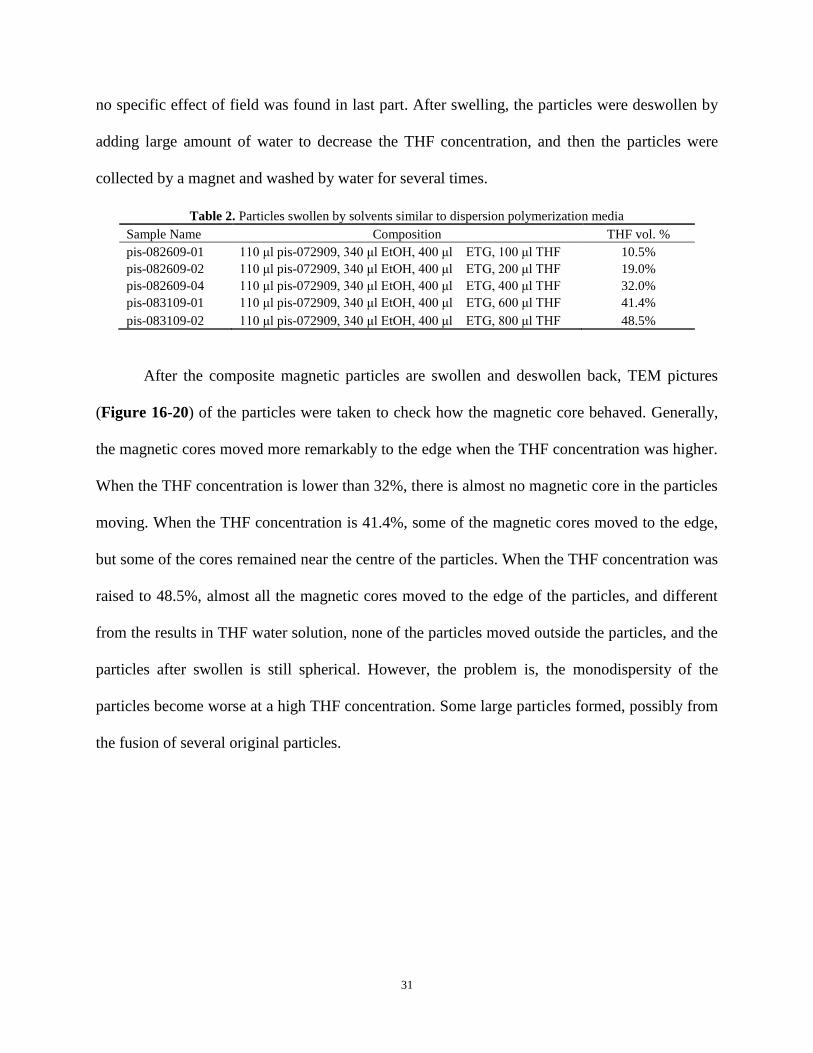
Figure 17. Transmission electron microscopy measurement of swollen magnetic composite
particles pis-082609-01 ................................................................................................................. 32
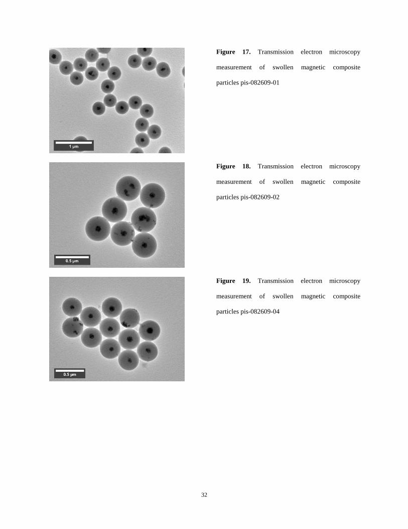
Figure 18. Transmission electron microscopy measurement of swollen magnetic composite
particles pis-082609-02 ................................................................................................................. 32
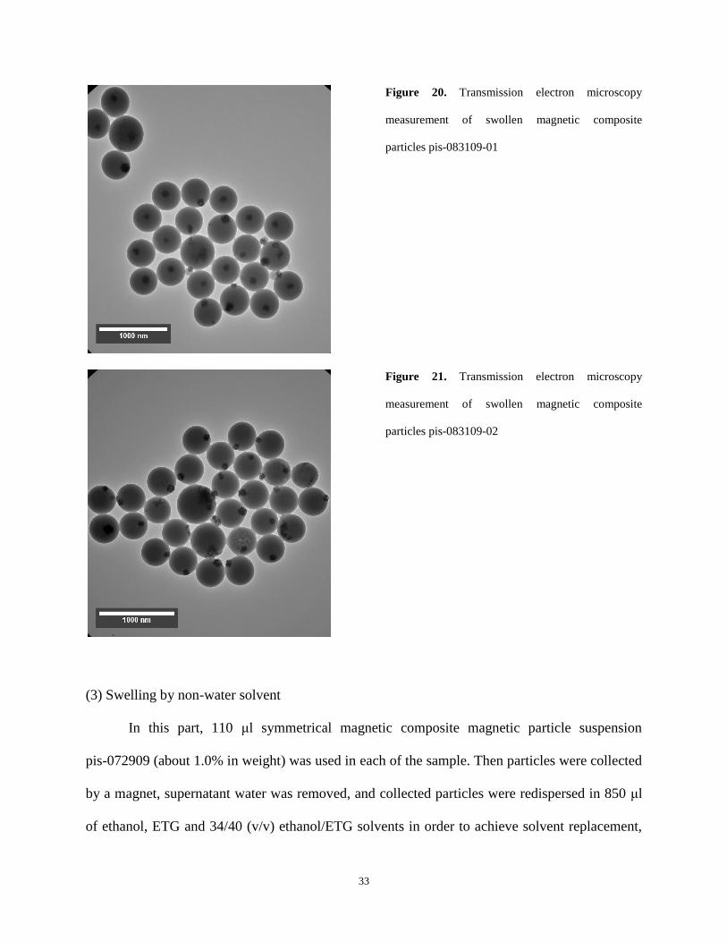
Figure 19. Transmission electron microscopy measurement of swollen magnetic composite
particles pis-082609-04 ................................................................................................................. 32
x
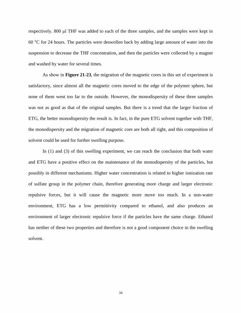
Figure 20. Transmission electron microscopy measurement of swollen magnetic composite
particles pis-083109-01 ................................................................................................................. 33
Figure 21. Transmission electron microscopy measurement of swollen magnetic composite
particles pis-083109-02 ................................................................................................................. 33
Figure 22. Transmission electron microscopy measurement of symmetrical core-shell magnetic
composite particles pis-072909 swollen by 850 μl ethanol and 800μl THF ................................ 35
Figure 23. Transmission electron microscopy measurement of symmetrical core-shell magnetic
composite particles pis-072909 swollen by 850 μl ETG and 800μl THF .................................... 35
Figure 24. Transmission electron microscopy measurement of symmetrical core-shell magnetic
composite particles pis-072909 swollen by 850 μl (34/40 v/v) ethanol/ETG solution and 800μl
THF ............................................................................................................................................... 35
Figure 25. Transmission electron microscopy measurement of symmetrical core-shell magnetic
composite particles pis-072909 protected by PVP-40: 110 μl particle suspension and 20 μl 0.05
g/ml PVP-40 solution .................................................................................................................... 37
Figure 26. Transmission electron microscopy measurement of symmetrical core-shell magnetic
composite particles pis-072909 protected by PVP-40: 110 μl particle suspension and 50 μl 0.05
g/ml PVP-40 solution .................................................................................................................... 37
Figure 27. Transmission electron microscopy measurement of symmetrical core-shell magnetic
composite particles pis-072909 protected by PVP-40: 110 μl particle suspension and 100 μl 0.05
g/ml PVP-40 solution .................................................................................................................... 38
Figure 28. Transmission electron microscopy measurement of symmetrical core-shell magnetic
composite particles pis-072909 protected by PVP-40: 110 μl particle suspension and 150 μl 0.05
g/ml PVP-40 solution .................................................................................................................... 38
xi
PREFACE
I would like to express my gratitude to my research advisor Prof. Sanford A. Asher, who guided
me through the course of my study and stimulated my thoughts. I also thank my thesis committee
members Prof. David Waldeck and Prof. Nathaniel Rosi for their helpful suggestions during the
manuscript preparation as well as discussions that helped me to finish my projects. Special
thanks to my senior coworkers Dr. Dan Qu, Dr. Justin Bohn, Dr. Sasha Tikhonov, Dr. Michelle
Muscatello and Dr. Sergei Bykov for their help in introducing me to the theoretical and
experimental aspects of colloid science. I also thank my graduate student peers: Jia Luo, Luling
Wang, Zhenmin Hong, Lu Ma, Kan Xiong and Bhavya Sharma for their participation in my
research projects and creating productive environment in the group. I also appreciate Dr. Thomas
Harper, Mr. Albert Stewart and Mr. Cole van Ormer for their help in the electron microscope
field.
And last, but not least I want to thank my parents, who gave me life and offered me
support all the time, and also my wife Dan, who always helped me and gave me truly family
warmth, and encouraged me to pursue my utmost career goal...…
1
1.0 INTRODUCTION TO POLYMER AND POLYMERIZATION
A polymer is a long molecule which contains a chain of atoms held together by covalent bonds.
Polymerization is a process by which monomer molecules react together chemically to form
either linear chains or a three-dimensional network of polymer chains.1
Polymerization could be generally divided into two large categories: chain-growth
polymerization (mainly addition reaction) and step-growth polymerization (mainly condensation
polymerization) by the way how the polymer chain grows. Chain-growth polymer is produced by
continuously adding monomer molecule to propagating center, and step-growth polymer is
formed by the stepwise reaction between functional groups of monomers. Chain-growth
polymerization includes mainly anionic polymerization, cationic polymerization and free radical
polymerization. In this work, we mainly use free radical polymerization as our experiment
method.
2
Figure 1. Difference between chain-growth polymerization and step-growth polymerization2
1.1 OVERVIEW OF RADICAL POLYMERIZATION
Radical polymerization is a type of polymerization in which the reactive center of a polymer
chain consists of a radical. This reaction process can be divided into three stages: initiation, chain
propagation and chain termination.
Initiation produces free radicals necessary for propagation. The radicals can be created
from radical initiators, such as organic peroxide molecules, or some other molecules containing
3
an OO single bond or NN double bond (azo-compound). The bond between the two oxygen
atoms breaks homogeneously or the two nitrogen atoms form nitrogen gas and escape to produce
two free radicals. Propagation is the rapid reaction of radical or radicalized monomer molecule
with another monomer molecule, with the lone electron of the radical attacking the
carbon-carbon double bond in the monomer. This reaction will generate a new radical with the
new reacted monomer linked at the end of this chain. Termination occurs when a radical reacts in
a way that prevents further propagation. The most common method of termination is the
coupling of two radical species, forming a single molecule. Another less common method is
chain disproportionation between two chain radical, generating one saturated chain and one
unsaturated by exchanging one proton.
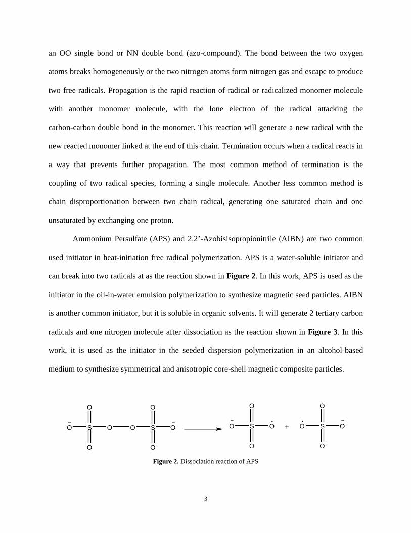
Ammonium Persulfate (APS) and 2,2’-Azobisisopropionitrile (AIBN) are two common
used initiator in heat-initiation free radical polymerization. APS is a water-soluble initiator and
can break into two radicals at as the reaction shown in Figure 2. In this work, APS is used as the
initiator in the oil-in-water emulsion polymerization to synthesize magnetic seed particles. AIBN
is another common initiator, but it is soluble in organic solvents. It will generate 2 tertiary carbon
radicals and one nitrogen molecule after dissociation as the reaction shown in Figure 3. In this
work, it is used as the initiator in the seeded dispersion polymerization in an alcohol-based
medium to synthesize symmetrical and anisotropic core-shell magnetic composite particles.
Figure 2. Dissociation reaction of APS
S
O
O
OO S
O
O
O O S
O
O
OO S
O
O
O O+

4
Figure 3. Dissociation reaction of AIBN
1.2 EMULSION POLYMERIZATION
Emulsion polymerization is a type of heterogeneous radical polymerization that is often used to
synthesize monodisperse polymer nanoparticles. In a typical emulsion polymerization, the
reaction starts with an emulsion of monomer, surfactant and reaction medium. The monomer is
insoluble (or its solubility is very small) in the polymerization medium, but is emulsified with the
help of the surfactant and exists mainly in the form of droplets. The initiator is soluble in the
medium but not in the monomer.3
After the temperature is raised above the initiation temperature, reaction first starts only
in the medium, forming oligomers which are either surrounded by dissolved monomer and
surfactant molecules or absorbed into already existing surfactant micelles. The formed
oligoradicals produce stabilized nuclei, and subsequently absorb other oligoradicals and
monomer from the medium or the monomer droplet, becoming the main location of the
polymerization. This reaction will continue until all monomer is consumed, leaving
monodispersed latex particles dispersed in water in the form of colloid.4
The emulsion polymerization used in this work is oil-in-water emulsion system, which
means that the monomer (styrene and methyl methacrylate) is hydrophobic, and the initiator
(ammonium persulfate) is in inorganic medium phase (water). Brij-35 (Aldrich), which is a
N N
CH3
CH3
CN
CH3
CH3
CN
CH3
CH3
CN
CH3
CH3
CN +
+ N2
5
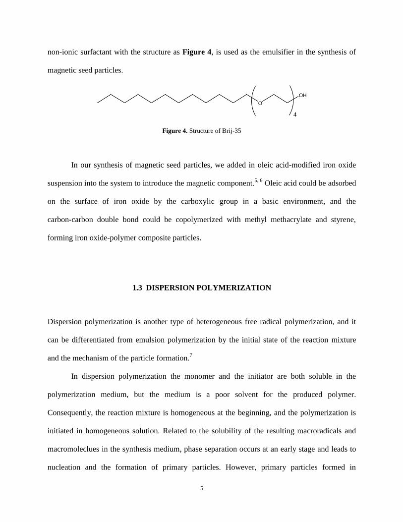
non-ionic surfactant with the structure as Figure 4, is used as the emulsifier in the synthesis of
magnetic seed particles.
Figure 4. Structure of Brij-35
In our synthesis of magnetic seed particles, we added in oleic acid-modified iron oxide
suspension into the system to introduce the magnetic component.5, 6
Oleic acid could be adsorbed
on the surface of iron oxide by the carboxylic group in a basic environment, and the
carbon-carbon double bond could be copolymerized with methyl methacrylate and styrene,
forming iron oxide-polymer composite particles.
1.3 DISPERSION POLYMERIZATION
Dispersion polymerization is another type of heterogeneous free radical polymerization, and it
can be differentiated from emulsion polymerization by the initial state of the reaction mixture
and the mechanism of the particle formation.7
In dispersion polymerization the monomer and the initiator are both soluble in the
polymerization medium, but the medium is a poor solvent for the produced polymer.
Consequently, the reaction mixture is homogeneous at the beginning, and the polymerization is
initiated in homogeneous solution. Related to the solubility of the resulting macroradicals and
macromoleclues in the synthesis medium, phase separation occurs at an early stage and leads to
nucleation and the formation of primary particles. However, primary particles formed in
O
OH
4
6
dispersion polymerization are swollen by the polymerization medium and/or the monomer. As a
result, polymerization proceeds largely in the individual particles, and finally forms spherical
particles.
Particle dispersions produced by dispersion polymerization in the absence of any
stabilizer are not sufficiently stable and may coagulate during their formation. Addition of a
small amount of a suitable stabilizer to the polymerization mixture produces stable particle
dispersions. Good stabilizers for dispersion polymerization are polymer and oligomer
compounds with low solubility in the polymerization medium and moderate affinity for the
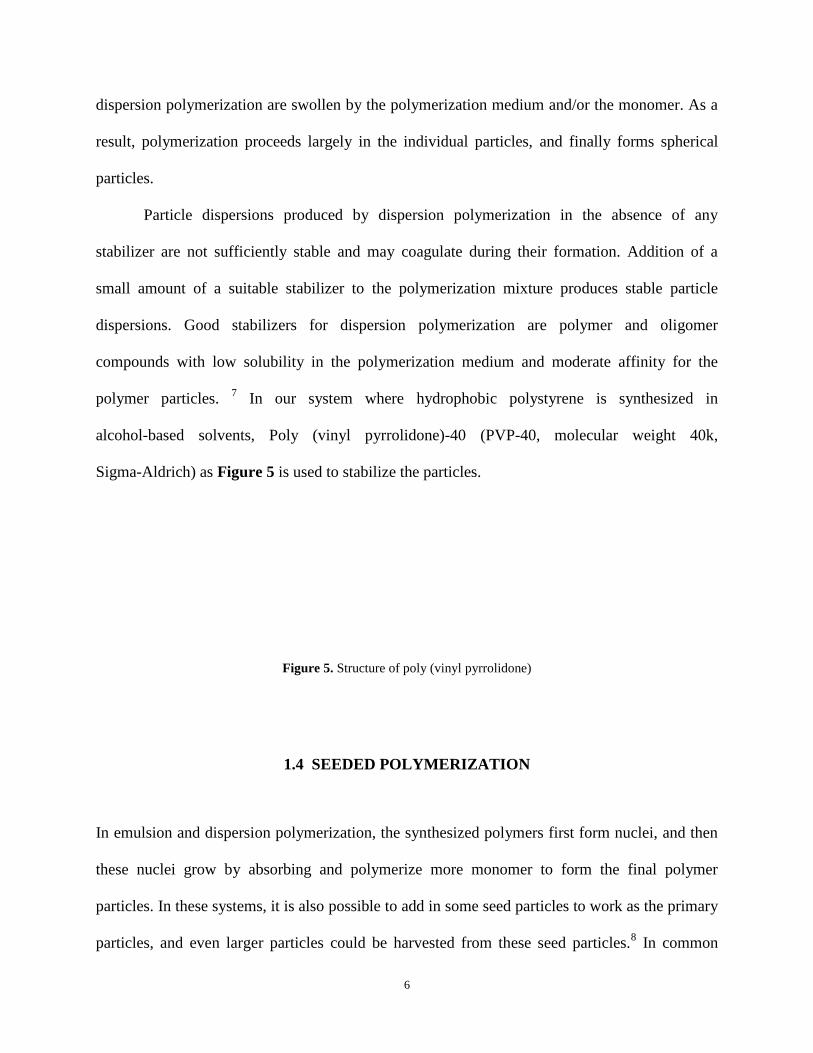
polymer particles. 7 In our system where hydrophobic polystyrene is synthesized in
alcohol-based solvents, Poly (vinyl pyrrolidone)-40 (PVP-40, molecular weight 40k,
Sigma-Aldrich) as Figure 5 is used to stabilize the particles.
Figure 5. Structure of poly (vinyl pyrrolidone)
1.4 SEEDED POLYMERIZATION
In emulsion and dispersion polymerization, the synthesized polymers first form nuclei, and then
these nuclei grow by absorbing and polymerize more monomer to form the final polymer
particles. In these systems, it is also possible to add in some seed particles to work as the primary
particles, and even larger particles could be harvested from these seed particles.8 In common
N
H
H
O
n

7
seeded polymerization, one of the most important issues the selection of a suitable
polymerization condition, under which no secondary nuclei will form; otherwise, the resulting
particles suspension will include particles of two or more sizes.
In this work, the symmetrical and anisotropic core-shell magnetic particles are
synthesized by a seeded dispersion polymerization. This two-step method makes it easier to
obtain relative large particles. Additionally, it also helps to better control the amount of iron
oxide contained in each composite particles and therefore decrease the polydispersity of
magnetic cores, since the amount of iron oxide is determined by the size of the seed particles
which are used in the dispersion polymerization.
1.5 THETA STATE AND POLYMER SWELLING
The theta state is defined as that state of a polymer solution at which the excess chemical
potential, and correspondingly, the excess of Gibbs energy of dilution is zero. For a given
polymer-solvent system, this state is obtained at a certain characteristic temperature, the theta
temperature Θ, and the solvent at this temperature is called a theta solvent.9
The exact definition of the theta state is given by chemical thermodynamics. The
chemical potential of a solvent l, Δμ1, can be split into an ideal term and an excess term:
Δμ1 = Δμ id1 + Δμ exc
1 (1)
Where the excess chemical potential at the thermodynamic temperature T is given by the
enthalpy of dilution, ΔH1, and the excess of entropy of dilution, ΔS exc1
Δμ exc1 = ΔH1 - TΔS exc
1 (2)
8
The theta state (zero excess chemical potential Δμ exc1 ) hence means that the terms at the
right side of Equation 2 compensate each other at the theta temperature Θ.
Generally speaking, if the temperature T is higher than the theta temperature Θ for a
specific polymer-solvent system of a concentration, the excess chemical potential will be
negative, meaning that the diluting process by more solvent is thermodynamically favorable and
that the polymer can be better dissolved. If the actual temperature is lower than Θ, the polymer
will precipitate in such a solvent.
Therefore, the theta temperature may also be phenomenologically defined as the critical
miscibility temperature. At the theta state, polymer-solvent interactions are just balanced by
polymer-polymer and solvent-solvent interactions, a critical situation just between dissolution
and precipitation. While at a temperature higher than the theta temperature, the same solvent as
in the theta state becomes a good solvent, and the polymer-solvent interactions are larger than the
polymer-polymer and solvent-solvent interactions. The polymer chain expands in order to
minimize polymer-polymer contacts, implicating that the polymer phase is dissolved in this
solvent.
Dissolution results from interactions between polymer-solvent, polymer-polymer and
solvent-solvent, we can change the property of a solvent gradually by changing the composition
of a mixed solvent: one is a good solvent for the polymer and the other is a poor solvent. If we
carefully control the composition and temperature to just a state near the theta state, it is possible
to swell the polymer particles while not completely dissolve them.
There are several solvents that have a theta temperature for styrene near or lower than
room temperature, including toluene, ethyl acetate and THF etc.9 Here THF is a better choice
than the other two, since THF is water-soluble; therefore, its concentration can be easily
9
controlled. It is also convenient to deswell particles by just diluting the THF solution to decrease
its concentration. Toluene and ethyl acetate are not soluble in water, and hence a longer time is
necessary for these two solvents to diffuse into the particles dispersed in water, and it is also
necessary to apply a high temperature to remove these swelling solvents when the swelling
process is ready.10
10
2.0 INTRODUCTION TO MAGNETISM
In physics, the term magnetism is used to describe the magnetic property of a material, and it is
defined by the respondence of a material to an applied magnetic field on the microscopic level.
Some are attracted to a magnetic field (paramagnetism); some are repulsed by a magnetic field
(diamagnetism); others have a much more complex relationship with an applied magnetic field
(including ferromagnetism, ferrimagnetism and antiferromagnetism, etc).
Magnetism mainly arises from two sources: electric currents, or more generally moving
electric charges, such as the electrons' orbital angular motion around the nucleus, and nonzero
"intrinsic" magnetic moments, such as the electrons' intrinsic magnetic moment. While the
magnetic behavior of a material depends on its structure listed above, it is also related to the
temperature, since at high temperatures, random thermal motion makes it more difficult for the
electrons to maintain alignment.
2.1 FERROMAGNETISM, FERRIMAGNETISM AND ANTIFERROMAGNETISM
Ferromagnetism, Ferrimagnetism and Antiferromagnetism are all properties of magnetic
materials, and the difference between them results from the arrangements of the magnetic atoms
or ions.11
(Figure 6)

11
Figure 6. Illustration of ferromagnetism, ferrimagnetism and antiferromagnetism
Ferromagnetism means that in a magnetic domain, all of the magnetic atoms or ions add a
positive contribution to the net magnetization. If some of the magnetic ions subtract from the net
magnetization, this property is called ferrimagnetism. If the moments of the aligned and
anti-aligned ions balance completely so as to have zero net magnetization, the materials is said to
have antiferromagnetism. All of these alignment effects only occur at temperatures below a
certain critical temperature, called the Curie temperature (for ferromagnets and ferrimagnets) or
the Neel temperature (for antiferromagnets).
Magnetic domain is a concept to describe a region within a magnetic material which has
uniform magnetization. The direction of magnetization inside a magnetic domain is the same,
and neighboring domains have different magnetization directions. The regions separating
magnetic domains are called domain walls where the magnetization directions change from one
direction to the other continuously. Magnetic domain structure is responsible for the magnetic
12
behavior of ferromagnetic and ferrimagnetic materials. When a ferromagnet or a ferrimagnet is
magnetized, the directions of different magnetic domains are aligned identical, and larger domain
will form from several smaller ones.
2.2 SUPERPARAMAGNETISM
Superparamagnetism is a form of magnetism, which appears in small ferromagnetic or
ferrimagnetics particle, when the particle size is smaller than the size of its magnetic domain. In
superparamagnets, the magnetic moments of different atoms or irons in one particle are exactly
ordered (ferromagnetic) or partially ordered (ferrimagnetic), but the direction of the
magnetization of each particle can randomly change due to the influence of thermal motion. In
this state, an external magnetic field is able to magnetize the small particles, similarly to a
paramagnet. However, their magnetic susceptibility is much larger than that of paramagnets.
When an external magnetic field is applied to superparamagnetic nanoparticles, they tend to
align along the magnetic field, leading to a net magnetization. And when the external field is
removed, the magnetization will disappear gradually, the rate related to both the size of materials
and the temperature.
Fe3O4 is generally a ferrimagnetic material, but it will express superparamagnetism when
its size is reduced to smaller than 35 nm at normal temperature.12
In our experiments, the size of
Fe3O4 is smaller than 15 nm; therefore, they are superparamagnetic materials in our experiments
and there is no macroscopic magnetization influencing the polymerization reaction.
13
3.0 CHAPTER 3: SYNTHESIS OF CORE-SHELL COMPOSITE MAGNETIC
PARTICLES AND CONTROLLABLE MIGRATION OF MAGNETIC CORE
3.1 MOTIVATION
Anisotropic particles have been a research subject of significant interest over several years.
Particle anisotropy can be in the form of shape, surface property or composite internal
distribution. In all of these cases, the anisotropic particles differ from isotropic particles,
potentially useful in engineering biomaterials and colloid structures. Lots of approaches have
been developed to synthesize such anisotropic particles13
, including micro-contact printing14
,
suspension polymerization15
, miniemulsion polymerization16, 17
, soap-free emulsion
polymerization18, 19, precipitation polymerization20
, phase-separation seed polymerization21, 22
,
decomposition reducing method23
, hydrothermal approach24
, and metal vapor deposition25, etc.
On the other hand, magnetic nanomaterials also receive special attention, since the
ferromagnetic, ferrimagnetic or superparamagnetic properties of these materials enable the control of
these materials by a magnetic way besides other conventional ways. Consequently, they have some
uncommon application, such as for drug delivery26
, magnetic biosensors27, magnetothermo therapy28,
magnetically controllable photonic crystals29-32 and nanoelectromechanical systems33, etc.
Therefore, materials with both anisotropy and magnetism will have even broader potential for
applications, since they will have the assets from both of these two kinds of materials. In this work
we developed a method to synthesize symmetric and anisotropic core-shell magnetic composite
14
particles and also an appropriate to move the magnetic core from one position to another inside the
particle. In the future work, we will explorer more about the controllable migration of the magnetic
core and use these particles as bricks to fabricate particles with multiple reactive sites and to build
photonic crystals.
3.2 EXPERIMENTAL METHODS
3.2.1 Materials:
FeCl3·6H2O (J. T. Baker), FeCl2·4H2O (Sigma-Aldrich), NH3·H2O (J. T. Baker),
Tetramethylammonium Hydroxide (TMAOH, Sigma-Aldrich), Hydrochloric Acid (J. T. Baker),
Oleic Acid (Aldrich), Styrene (Aldrich), Methyl Methacrylate (MMA, Polysciences), Sodium
p-Styrenesulfonate (NaSS, Aldrich), Ammonium Persulfate (APS, Aldrich),
2,2’-Azobisisopropionitrile (AIBN, Aldrich), Polyvinylpyrrolidone-40 (PVP-40, molecular
weight 40,000, Sigma-Aldrich), Brij-35 (Molecular weight 362.5, Aldrich), Ethanol (EtOH,
Pharmco-AAPER), Ethylene Glycol (ETG, J. T. Baker), Tetrahydrofuran (THF, EMD Chemicals)
were all used as received.
3.2.2 Equipments:
Transmission Electron Microscope (TEM, JEOL 200CX and Philips Mogagni 268),
Carboncoated Copper Grid (Ted Pella, Inc.), Dynamic Light Scattering Photometer (DLS,
Brookhaven Z-90 plus)
15
3.2.3 Synthesis of iron oxide magnetic nanoparticles:
Nanoscale iron oxide was prepared by the coprecipitation of ferric and ferrous ions in
ammonium hydroxide solution.32, 34-37
A 5.4 g portion of FeCl3·6H2O and 4.0 g FeCl2·4H2O were
dissolved in 25 ml water, and this resulting solution was poured into 250 ml of 1.0 M NH3·H2O
solution while mechanically stirred at a rate of 350 rpm. After 10 minutes’ stirring, the resulting
black precipitate was collected with a magnet, and the supernatant was discarded. A 250 ml
portion of 0.4 M TMAOH solution was added to the precipitate, and the mixture was sonicated
for 1 hour. After this sonication, 1.25 g oleic acid was added into the particle suspension to
modify the magnetic colloid surface properties.
3.2.4 Synthesis of magnetic composite seed particles:
Magnetic composite seed particles were synthesized by emulsion polymerization of styrene and
MMA in the presence of the above iron oxide magnetic nanoparticles by modifying Xu et al’s
methods.32
These particles were synthesized by using a jacketed cylindrical reaction vessel
containing a reflux condenser, a Teflon mechanical stirrer, an additional funnel and a nitrogen
inlet. The temperature was controlled through the jacket with the use of a circulating temperature
bath. A nitrogen blanket and a stirring rate of 350 rpm were maintained throughout the
polymerization.
In a typical synthesis, 10 ml of the above iron oxide suspension was diluted by 10 ml
water and further modified by another 0.13 g oleic acid. Then 2.8 g 0.1g/L Brij-35 nonionic
surfactant solution was added into the iron oxide suspension, and 5 ml 0.02 g/ml NaSS solution
16
and 72 ml water were added. This suspension was well stirred and the pH of this suspension was
adjusted to 12.3 by hydrochloric acid.
This modified iron oxide suspension was transferred into the jacket reactor and purged
with N2 for 30 minutes at a stir rate of 60 rpm. Simultaneously, 10 ml styrene and 1.5 ml MMA
were added into the addition funnel and also purged N2 for 30 minutes. After 30 minutes, the
circulating bash was turned on to increase the reaction temperature to 50 °C, and the stir rate was
raised to 350 rpm. 5 minutes after the temperature reached 50 °C, the N2 blanketing was started,
and the mixture of the MMA and styrene were added into the reactor at a constant rate. After
another 10 minutes’ stirring at 50 °C, the reactor temperature was increased to 70 °C. When the
temperature reached 70 °C, 5 ml 16.7% (weight fraction) APS water solution was injected into
the reactor to start the polymerization, and the polymerization was carried out for 4 hours. After
the reaction was finished, the product suspension appeared brown. A magnet was used to collect
synthesized particles containing iron oxide nanoclusters inside. The collected particles were
washed with water several times to remove pure polymer particles. At last, this particle
suspension was diluted to 20 ml and the weight percentage is determined to be ~1.0 % by drying
this suspension.
3.2.5 Synthesis of symmetrical and anisotropic core-shell magnetic composite particles:
Symmetrical and anisotropic core-shell magnetic composite particles were synthesized by
dispersion polymerization with the above composite particles as seeds in several alcohol-based
solvents in the same reactors as last part. The anisotropy or symmetry could be achieved by
simply adjusting the composition of the reaction medium made from water, EtOH, ETG and
THF.
17
In a typical synthesis, 6 ml 0.05 g/ml PVP-40 ethanol solution as a particle stabilizer was
added to 6 ml of the seed particle suspension, and this mixture was added into a specific
alcohol-based polymerization medium (as shown in Table 1). This mixture suspension was
transferred into the reactor, and then N2 was purged into this suspension for 30 minutes while
mechanically stirring at 120 rpm. After 30 minutes, the N2 blanketing was started, and the stir
rate was raised to 350 rpm. 3 ml styrene and 3 ml 0.01 g/ml AIBN ethanol solution were injected
to the reactor. After another 20 minutes’ stirring was applied to the reactor, the temperature of
the reactor was increased to 60 °C to start the polymerization, and this reaction was carried out
for 3 hours and 40 minutes. After the reaction was finished, the product suspension appeared
pale-yellow. A magnet was used to collect synthesized particles containing iron oxide magnetic
cores. The collected particles were washed with water several times to remove pure polymer
particles and then diluted to 20 ml.
3.2.6 Migration of magnetic core in core-shell magnetic composite particles:
The migration of magnetic core inside core-shell magnetic composite particles was achieved by
solvent swelling, with or without the presence of a magnetic field. Particles of different structure
could be obtained by the change of solvent composition, swelling temperature or length of
swelling time. Generally, a small amount of core-shell magnetic composite particles were
dispersed at a low concentration in a mixture solvent made from water, EtOH, ETG, THF, and
sometimes PVP-40 was used as stabilizer. Then this suspension was sealed in a glass vial and
left still at room temperature for 1 hour to let particles reach equilibrium. Subsequently, this
suspension was placed in a 60°C or 70°C oven for up to 48 hours, letting magnetic cores migrate
inside particles, and at last this suspension was quenched by a large amount of water to deswell

18
the particles and lock the position of the magnetic core. These resulting particles were washed
with water and collected by a magnet for several times.
3.2.7 Structure analysis of particles:
The size and structure of particles synthesized were analyzed by TEM (200 kV for JEOL 200CX
and 80 kV for Philips Mogagni 268) after drying several drops of particles suspension on a
carboncoated copper grid. The size and size distribution of some of the particles were also
analyzed by DLS after diluting particle suspensions in water.
3.3 RESULTS AND DISCUSSION
3.3.1 Synthesis of iron oxide magnetic nanoparticles
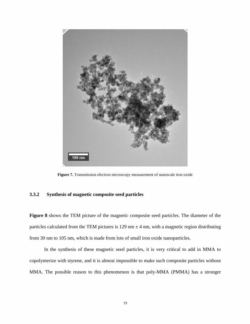
Figure 7 shows the TEM picture of the iron oxide magnetic nanoparticles. The iron oxide
nanoparticles have a broad size distribution of 2-15 nm, and the average diameter is about 10 nm.
According to Xu’s work before32
, iron oxide synthesized in this coprecipitation method is
superparamagnetic. These iron oxide magnetic nanoparticles are modified by oleic acid and
stabilized in 0.4 M TMAOH for further use.
19
Figure 7. Transmission electron microscopy measurement of nanoscale iron oxide
3.3.2 Synthesis of magnetic composite seed particles
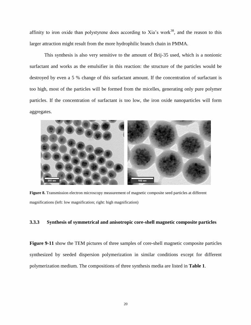
Figure 8 shows the TEM picture of the magnetic composite seed particles. The diameter of the
particles calculated from the TEM pictures is 129 nm ± 4 nm, with a magnetic region distributing
from 30 nm to 105 nm, which is made from lots of small iron oxide nanoparticles.
In the synthesis of these magnetic seed particles, it is very critical to add in MMA to
copolymerize with styrene, and it is almost impossible to make such composite particles without
MMA. The possible reason to this phenomenon is that poly-MMA (PMMA) has a stronger
20
affinity to iron oxide than polystyrene does according to Xia’s work38
, and the reason to this
larger attraction might result from the more hydrophilic branch chain in PMMA.
This synthesis is also very sensitive to the amount of Brij-35 used, which is a nonionic
surfactant and works as the emulsifier in this reaction: the structure of the particles would be
destroyed by even a 5 % change of this surfactant amount. If the concentration of surfactant is
too high, most of the particles will be formed from the micelles, generating only pure polymer
particles. If the concentration of surfactant is too low, the iron oxide nanoparticles will form
aggregates.
Figure 8. Transmission electron microscopy measurement of magnetic composite seed particles at different
magnifications (left: low magnification; right: high magnification)
3.3.3 Synthesis of symmetrical and anisotropic core-shell magnetic composite particles
Figure 9-11 show the TEM pictures of three samples of core-shell magnetic composite particles
synthesized by seeded dispersion polymerization in similar conditions except for different
polymerization medium. The compositions of three synthesis media are listed in Table 1.
21
Table 1. Composition of solvents used in dispersion polymerization of core-shell magnetic
particle synthesis and corresponding particle morphologies
Sample Name Solvent composition Resulting particle morphology
pis-072909 11 ml water, 34 ml EtOH, 40 ml ETG Symmetrical, monodisperse
pis-080709 11 ml water, 34 ml EtOH, 40 ml ETG, 10 ml THF Anisotropic, monodisperse
pis-082009 27 ml water, 57 ml EtOH, 10 ml THF Anisotropic, not monodisperse
As shown in Table 1 and Figure 9-11, three samples synthesized in different media
showed different structures and polydispersities, even they were made from the same seed
particle and under identical other experimental conditions. All these three samples have in the
polymer sphere a concentrated magnetic core, which is made from lots of small iron oxide
nanoparticles and whose size is directly determined by the iron oxide content contained in the
seed composite particles.
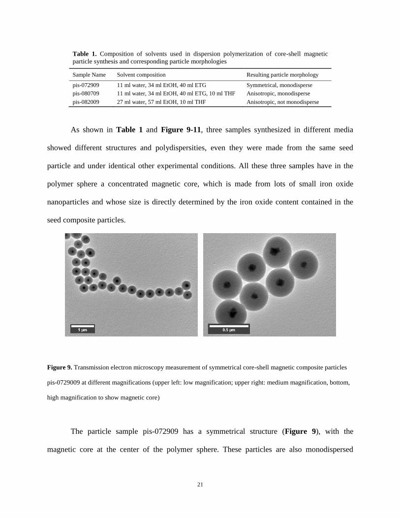
Figure 9. Transmission electron microscopy measurement of symmetrical core-shell magnetic composite particles
pis-0729009 at different magnifications (upper left: low magnification; upper right: medium magnification, bottom,
high magnification to show magnetic core)
The particle sample pis-072909 has a symmetrical structure (Figure 9), with the
magnetic core at the center of the polymer sphere. These particles are also monodispersed
22
generally, with the average diameter 381 nm ± 20 nm determined from TEM picture. The solvent
used in the synthesis of this sample is mixture of 11 ml water, 34 ml ethanol and 40 ETG, which
is not a good solvent for polystyrene nor PMMA. Consequently, the seed particle polymer matrix
remains its original structure during the polymerization, and the magnetic core remains at the
center of the particle with new-formed polystyrene growing at the surface of the outer shell
homogeneously.
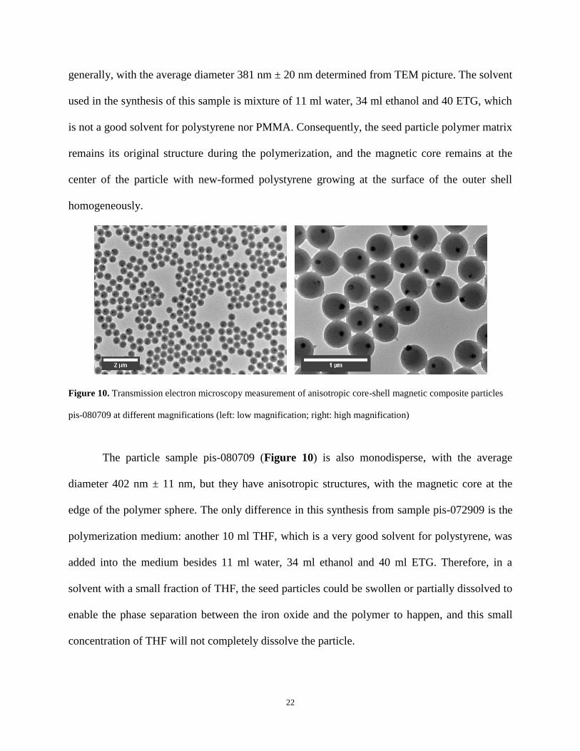
Figure 10. Transmission electron microscopy measurement of anisotropic core-shell magnetic composite particles
pis-080709 at different magnifications (left: low magnification; right: high magnification)
The particle sample pis-080709 (Figure 10) is also monodisperse, with the average
diameter 402 nm ± 11 nm, but they have anisotropic structures, with the magnetic core at the
edge of the polymer sphere. The only difference in this synthesis from sample pis-072909 is the
polymerization medium: another 10 ml THF, which is a very good solvent for polystyrene, was
added into the medium besides 11 ml water, 34 ml ethanol and 40 ml ETG. Therefore, in a
solvent with a small fraction of THF, the seed particles could be swollen or partially dissolved to
enable the phase separation between the iron oxide and the polymer to happen, and this small
concentration of THF will not completely dissolve the particle.
23
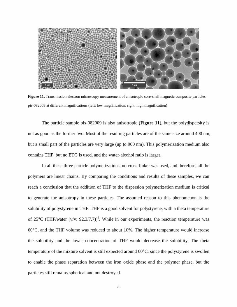
Figure 11. Transmission electron microscopy measurement of anisotropic core-shell magnetic composite particles
pis-082009 at different magnifications (left: low magnification; right: high magnification)
The particle sample pis-082009 is also anisotropic (Figure 11), but the polydispersity is
not as good as the former two. Most of the resulting particles are of the same size around 400 nm,
but a small part of the particles are very large (up to 900 nm). This polymerization medium also
contains THF, but no ETG is used, and the water-alcohol ratio is larger.
In all these three particle polymerizations, no cross-linker was used, and therefore, all the
polymers are linear chains. By comparing the conditions and results of these samples, we can
reach a conclusion that the addition of THF to the dispersion polymerization medium is critical
to generate the anisotropy in these particles. The assumed reason to this phenomenon is the
solubility of polystyrene in THF. THF is a good solvent for polystyrene, with a theta temperature
of 25°C (THF/water (v/v: 92.3/7.7))9. While in our experiments, the reaction temperature was
60°C, and the THF volume was reduced to about 10%. The higher temperature would increase
the solubility and the lower concentration of THF would decrease the solubility. The theta
temperature of the mixture solvent is still expected around 60°C, since the polystyrene is swollen
to enable the phase separation between the iron oxide phase and the polymer phase, but the
particles still remains spherical and not destroyed.
24
From these experiments, we can also obtain some conclusion about the polydispersity.
The dispersion polymerization without ETG in the medium gave out a result of a poor
polydispersity. The mechanism of ETG’s effect here is not clear, but one possible explanation to
this phenomenon could be attributed to the lower dielectric constant of ETG. The high
concentration of ETG in the polymerization medium results in lower dielectric constant of the
medium, and it therefore allows higher electronic repulsive force (inverse proportional to the
dielectric constant) between individual particles to prevent them from approaching one another.
3.3.4 Swelling of symmetrical core-shell magnetic composite particles
One objective of this project is to magnetically control the magnetic core migration of the
composite particles. And this part is a preparatory work to the total objective, since it will give a
condition under which the polymer properties of the magnetic composite particles can be
changed enough to enable such migration and under which the magnetic core made from small
iron oxide clusters would not be destroyed.
THF is selected as the effective part of the mixture solvent, since it is a good solvent for
polystyrene, and the theta condition for this pair9 is: THF/water (v/v: 92.3/7.7), theta temperature:
25°C. Some work has been done on the swelling effect of styrene by THF, such as in 39
,
styrene particles can be best swollen by 50% THF water solution at room temperature, with the
diameter largest measured by DLS. If the THF concentration is lower, the polystyrene particles
would be less effectively swollen, and if the THF concentration is higher, the polystyrene chains
would be removed from the particle into the solvent, causing the dissociation of the particles.
After the swelling, it is also very convenient to deswell the particles by just diluting the solvent
25
to decrease THF concentration, making the particles contract to almost the original size. Since
the temperature used in this lab is a little higher, a lower concentration of THF might also work.
(1) Swelling by THF water solution
In this part, THF water solutions with THF volume fraction 50%, 40%, 30% and 20%
were used. At each concentration, two parallel particle samples were swollen under magnetic
field and without magnetic field. The temperature of the swelling is 70 °C and the swelling
duration is 48 hours. After 48 hours, the particles were deswollen by adding large amount of
water into the particle suspension. Later, particles are collected by a magnet, and washed several
times with water.
From the TEM picture of all the four sets samples (Figures 12-15), it can be seen that the
magnetic core of the composite magnetic particles moved from the center to the outside of the
polymer sphere. The shape of the magnetic core were kept, and the size of the magnetic region
became a little smaller than in the magnetic seed particles. Generally, there is a one-to-one
linkage between migrated magnetic core and its original polymer particle in most of the samples
(the only exception is in 50% THF solution, under magnetic field), and this linkage was strong,
since the magnetic core kept its position even under the very strong surface tension when drying
on TEM grid and in the high vacuum of TEM measurements.
The mechanism of this core movement is not clear, but one possible reason could be
attributed to the minimization of interfacial free energy between different phases:
polystyrene/PMMA, polystyrene/solvent and PMMA/solvent. The formation of the original
composite core-shell particles might be a kinetic process: polystyrene grows continuously on the
surface of existing particles, and therefore, the structure might not be at the global minimum of
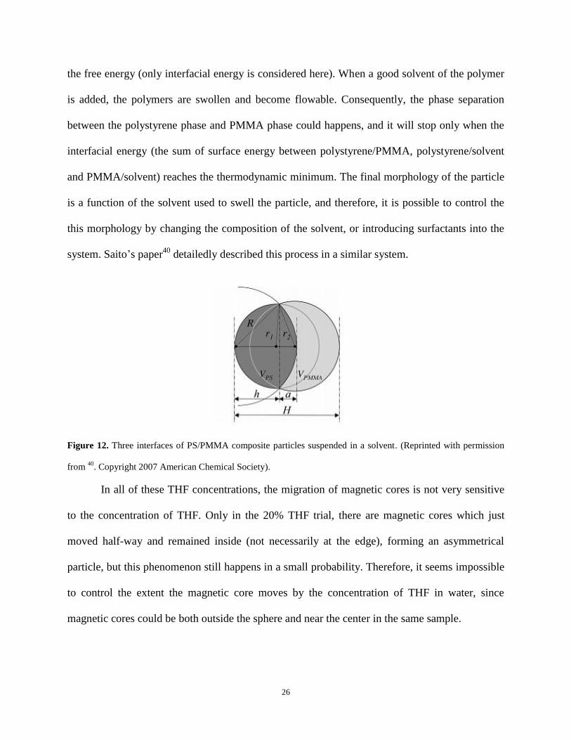
26
the free energy (only interfacial energy is considered here). When a good solvent of the polymer
is added, the polymers are swollen and become flowable. Consequently, the phase separation
between the polystyrene phase and PMMA phase could happens, and it will stop only when the
interfacial energy (the sum of surface energy between polystyrene/PMMA, polystyrene/solvent
and PMMA/solvent) reaches the thermodynamic minimum. The final morphology of the particle
is a function of the solvent used to swell the particle, and therefore, it is possible to control the
this morphology by changing the composition of the solvent, or introducing surfactants into the
system. Saito’s paper40
detailedly described this process in a similar system.
Figure 12. Three interfaces of PS/PMMA composite particles suspended in a solvent. (Reprinted with permission
from 40
. Copyright 2007 American Chemical Society).
In all of these THF concentrations, the migration of magnetic cores is not very sensitive
to the concentration of THF. Only in the 20% THF trial, there are magnetic cores which just
moved half-way and remained inside (not necessarily at the edge), forming an asymmetrical
particle, but this phenomenon still happens in a small probability. Therefore, it seems impossible
to control the extent the magnetic core moves by the concentration of THF in water, since
magnetic cores could be both outside the sphere and near the center in the same sample.
27
The concentration of THF has some effect on the polydispersity of the particles at this
concentration range, but it is not very remarkable. At higher THF concentration (50%), some
particles may fuse and form larger ones, while at lower (20% or 30%), most particles are still of
their original size.
The magnetic field applied to the particles suspensions during the swelling process had
almost no effect to the final results. Almost no difference could be recognized between the
samples swollen with and without magnetic field, and the only one that can be found is that at
high concentration (50%), the samples swollen under field did not show an exact one-to-one
magnetic core – polymer sphere ratio.
This part is also an evidence of the strong repulsive interaction between individual
particles. When the particles were swollen under magnetic field, they were all attracted to the
wall soon, forming a yellow block at the wall of the glass vial and leaving clear supernatant.
However, even at the highest concentration (50% THF, where particles are fully swollen), the
particles did not fuse together or form a huge polymer clump even after 48 hours at 70°C and can
be redispersed into particle suspension by simple shaking for several seconds, which is a definite
evidence of the existence of high repulsive forces between particles.
28
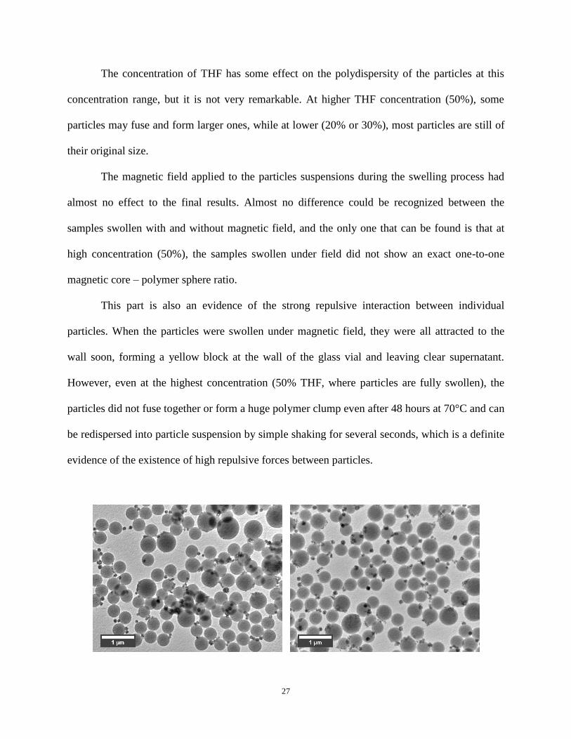
Figure 13. Transmission electron microscopy measurement of symmetrical core-shell magnetic composite particles
pis-072909 swollen by 50% (v/v) THF water solution (left: swollen under magnetic field; right: swollen without
magnetic field)
Figure 14. Transmission electron microscopy measurement of symmetrical core-shell magnetic composite particles
pis-072909 swollen by 40% (v/v) THF water solution (left: swollen under magnetic field; right: swollen without
magnetic field)
29
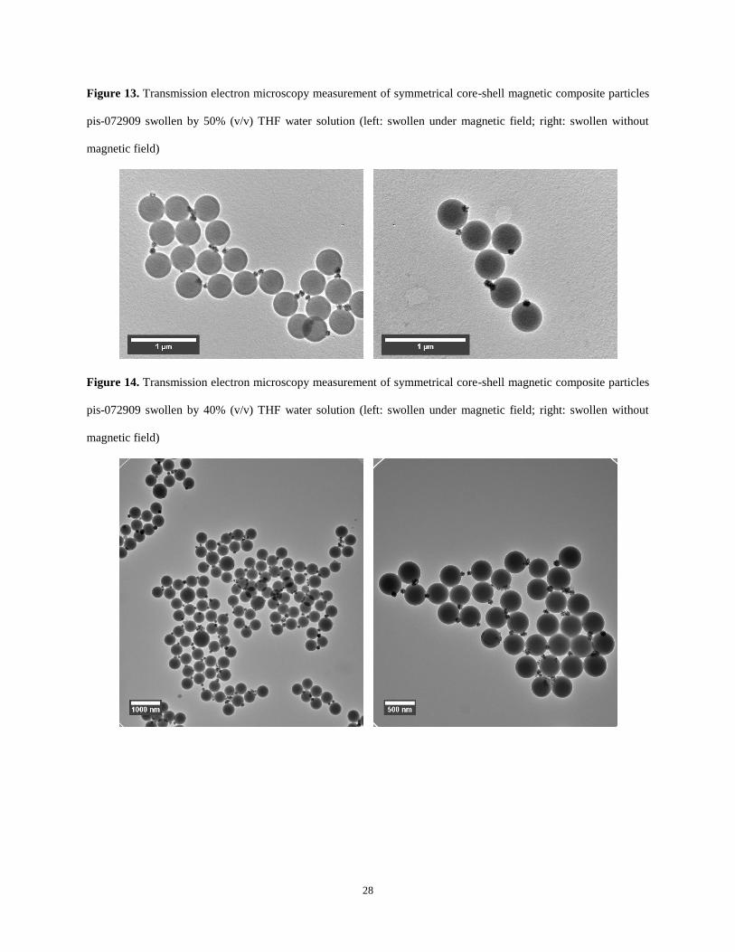
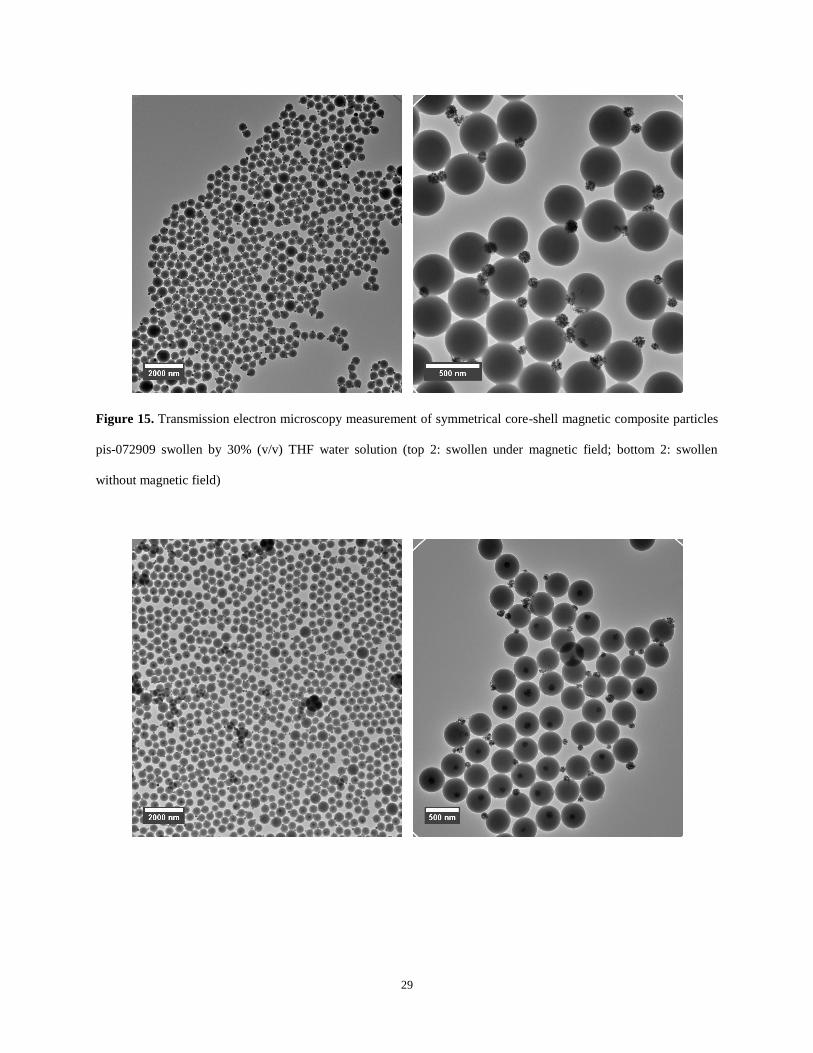
Figure 15. Transmission electron microscopy measurement of symmetrical core-shell magnetic composite particles
pis-072909 swollen by 30% (v/v) THF water solution (top 2: swollen under magnetic field; bottom 2: swollen
without magnetic field)
30
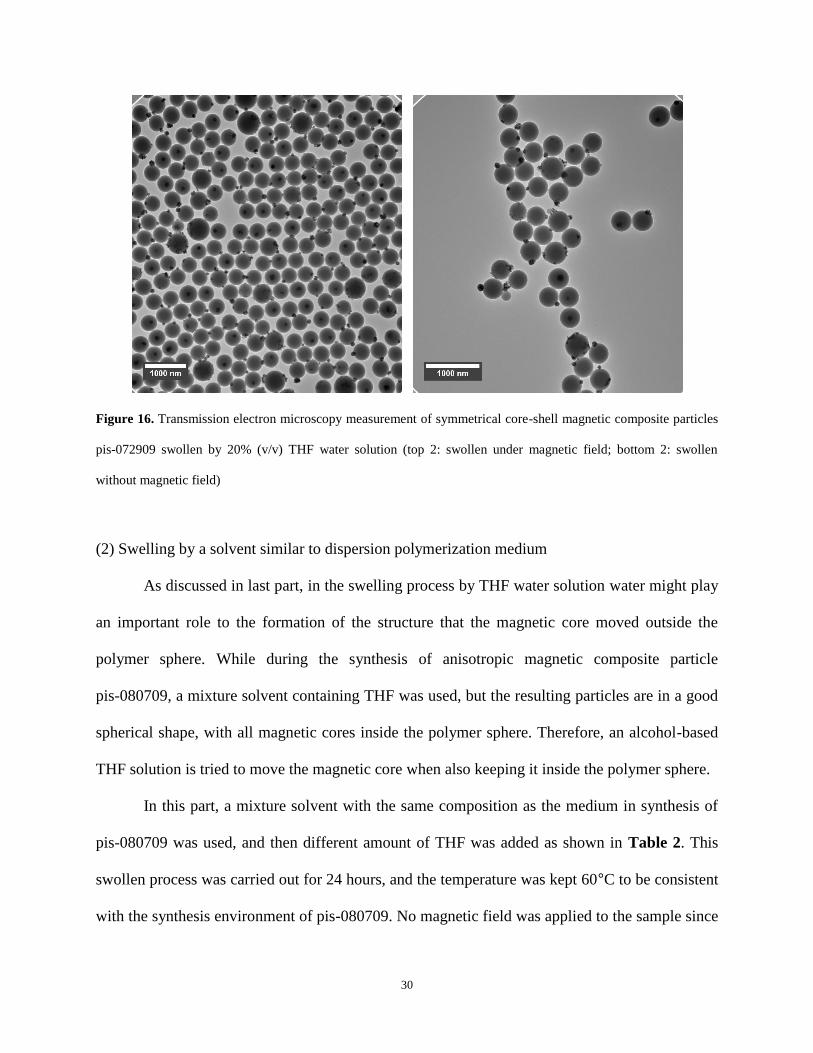
Figure 16. Transmission electron microscopy measurement of symmetrical core-shell magnetic composite particles
pis-072909 swollen by 20% (v/v) THF water solution (top 2: swollen under magnetic field; bottom 2: swollen
without magnetic field)
(2) Swelling by a solvent similar to dispersion polymerization medium
As discussed in last part, in the swelling process by THF water solution water might play
an important role to the formation of the structure that the magnetic core moved outside the
polymer sphere. While during the synthesis of anisotropic magnetic composite particle
pis-080709, a mixture solvent containing THF was used, but the resulting particles are in a good
spherical shape, with all magnetic cores inside the polymer sphere. Therefore, an alcohol-based
THF solution is tried to move the magnetic core when also keeping it inside the polymer sphere.
In this part, a mixture solvent with the same composition as the medium in synthesis of
pis-080709 was used, and then different amount of THF was added as shown in Table 2. This
swollen process was carried out for 24 hours, and the temperature was kept 60°C to be consistent
with the synthesis environment of pis-080709. No magnetic field was applied to the sample since
31
no specific effect of field was found in last part. After swelling, the particles were deswollen by
adding large amount of water to decrease the THF concentration, and then the particles were
collected by a magnet and washed by water for several times.
Table 2. Particles swollen by solvents similar to dispersion polymerization media
Sample Name Composition THF vol. %
pis-082609-01 110 μl pis-072909, 340 μl EtOH, 400 μl ETG, 100 μl THF 10.5%
pis-082609-02 110 μl pis-072909, 340 μl EtOH, 400 μl ETG, 200 μl THF 19.0%
pis-082609-04 110 μl pis-072909, 340 μl EtOH, 400 μl ETG, 400 μl THF 32.0%
pis-083109-01 110 μl pis-072909, 340 μl EtOH, 400 μl ETG, 600 μl THF 41.4%
pis-083109-02 110 μl pis-072909, 340 μl EtOH, 400 μl ETG, 800 μl THF 48.5%
After the composite magnetic particles are swollen and deswollen back, TEM pictures
(Figure 16-20) of the particles were taken to check how the magnetic core behaved. Generally,
the magnetic cores moved more remarkably to the edge when the THF concentration was higher.
When the THF concentration is lower than 32%, there is almost no magnetic core in the particles
moving. When the THF concentration is 41.4%, some of the magnetic cores moved to the edge,
but some of the cores remained near the centre of the particles. When the THF concentration was
raised to 48.5%, almost all the magnetic cores moved to the edge of the particles, and different
from the results in THF water solution, none of the particles moved outside the particles, and the
particles after swollen is still spherical. However, the problem is, the monodispersity of the
particles become worse at a high THF concentration. Some large particles formed, possibly from
the fusion of several original particles.
32
Figure 17. Transmission electron microscopy
measurement of swollen magnetic composite
particles pis-082609-01
Figure 18. Transmission electron microscopy
measurement of swollen magnetic composite
particles pis-082609-02
Figure 19. Transmission electron microscopy
measurement of swollen magnetic composite
particles pis-082609-04
33
Figure 20. Transmission electron microscopy
measurement of swollen magnetic composite
particles pis-083109-01
Figure 21. Transmission electron microscopy
measurement of swollen magnetic composite
particles pis-083109-02
(3) Swelling by non-water solvent
In this part, 110 μl symmetrical magnetic composite magnetic particle suspension
pis-072909 (about 1.0% in weight) was used in each of the sample. Then particles were collected
by a magnet, supernatant water was removed, and collected particles were redispersed in 850 μl
of ethanol, ETG and 34/40 (v/v) ethanol/ETG solvents in order to achieve solvent replacement,
34
respectively. 800 μl THF was added to each of the three samples, and the samples were kept in
60 °C for 24 hours. The particles were deswollen back by adding large amount of water into the
suspension to decrease the THF concentration, and then the particles were collected by a magnet
and washed by water for several times.
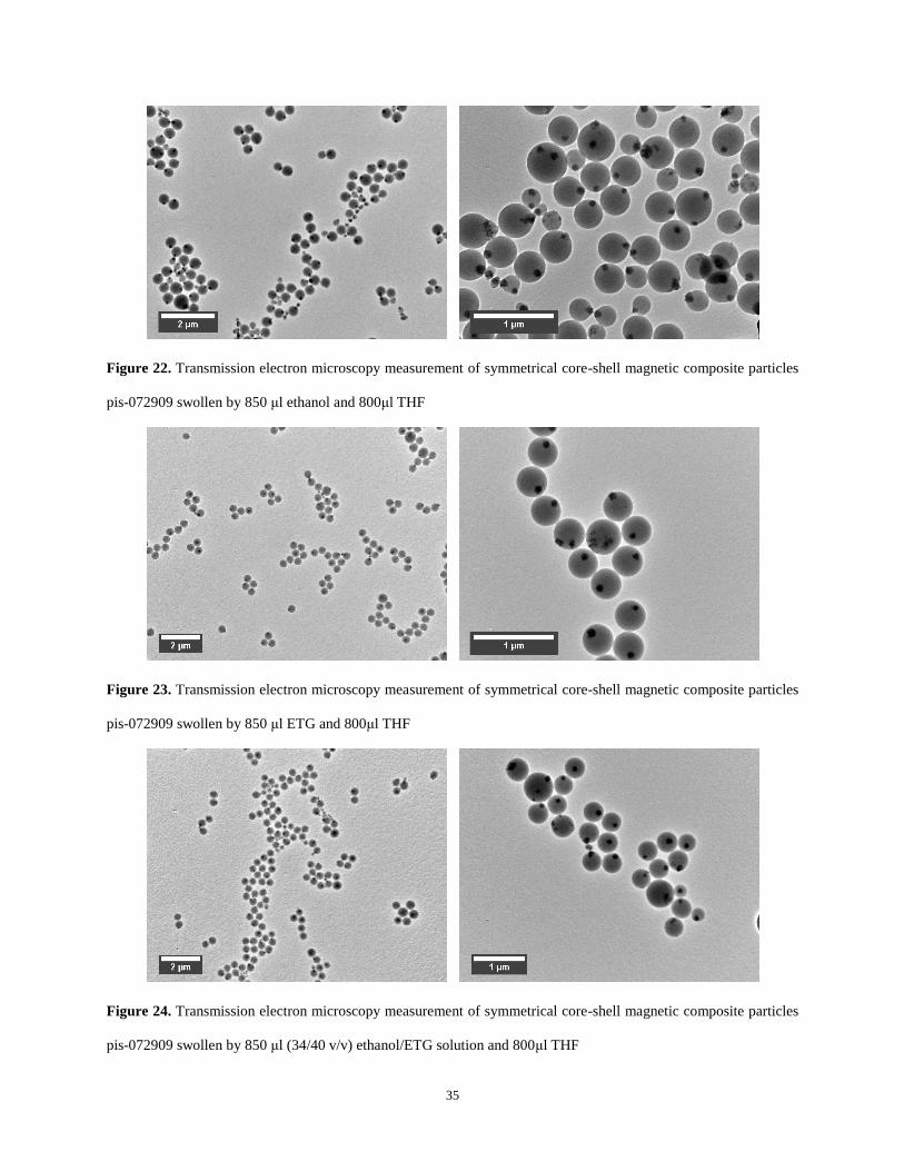
As show in Figure 21-23, the migration of the magnetic cores in this set of experiment is
satisfactory, since almost all the magnetic cores moved to the edge of the polymer sphere, but
none of them went too far to the outside. However, the monodispersity of these three samples
was not as good as that of the original samples. But there is a trend that the larger fraction of
ETG, the better monodispersity the result is. In fact, in the pure ETG solvent together with THF,
the monodispersity and the migration of magnetic core are both all right, and this composition of
solvent could be used for further swelling purpose.
In (1) and (3) of this swelling experiment, we can reach the conclusion that both water
and ETG have a positive effect on the maintenance of the monodispersity of the particles, but
possibly in different mechanisms. Higher water concentration is related to higher ionization rate
of sulfate group in the polymer chain, therefore generating more charge and larger electronic
repulsive forces, but it will cause the magnetic more move too much. In a non-water
environment, ETG has a low permittivity compared to ethanol, and also produces an
environment of larger electronic repulsive force if the particles have the same charge. Ethanol
has neither of these two properties and therefore is not a good component choice in the swelling
solvent.
35
Figure 22. Transmission electron microscopy measurement of symmetrical core-shell magnetic composite particles
pis-072909 swollen by 850 μl ethanol and 800μl THF
Figure 23. Transmission electron microscopy measurement of symmetrical core-shell magnetic composite particles
pis-072909 swollen by 850 μl ETG and 800μl THF
Figure 24. Transmission electron microscopy measurement of symmetrical core-shell magnetic composite particles
pis-072909 swollen by 850 μl (34/40 v/v) ethanol/ETG solution and 800μl THF
36
(4) Swelling by alcohol-based THF solution while protected by PVP-40 as stabilizer
In the last several parts, it has been proved that mixture solvent of water, ethanol, ETG
and THF could effectively swell the magnetic composite particles and enable the magnetic core
to migrate to the edge from the center. In order to solve the problem that the fusion happened
between particles when they were swollen by high concentration of THF, another method is
tested. PVP-40 was used as stabilizer to protect particles from getting too close to one another,
forming new larger particles and therefore further destroying the monodispersity.
In this part, 110 μl symmetrical magnetic composite particle pis-072909 suspension
(about 1.0% in weight) was used in each of the sample, and then 340 μl ethanol and 400 μl ETG
were added in. Then 20, 50, 100 and150 μl 0.05 g/ml PVP-40 ethanol solution were added into
the four samples, respectively. All swelling processes were carried out at 60 °C for 24 hours, and
then the particles were deswollen back by adding large amount of water into the suspension to
decrease the THF concentration. Then the particles were collected by a magnet and washed by
water for several times.
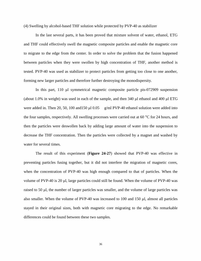
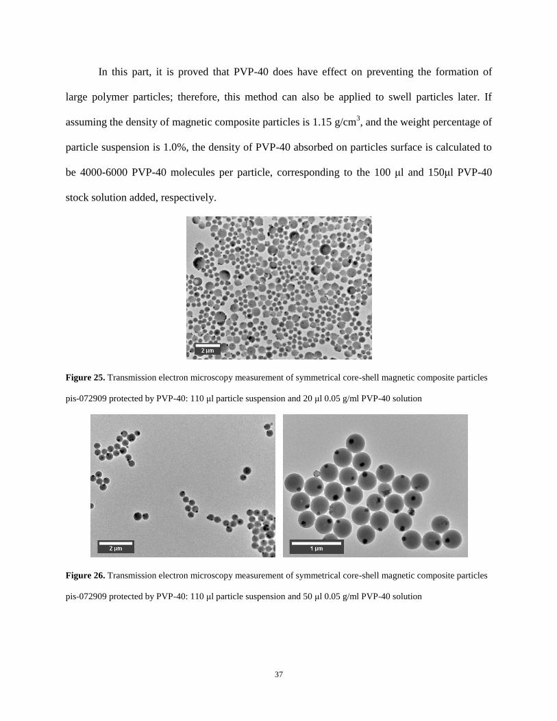
The result of this experiment (Figure 24-27) showed that PVP-40 was effective in
preventing particles fusing together, but it did not interfere the migration of magnetic cores,
when the concentration of PVP-40 was high enough compared to that of particles. When the
volume of PVP-40 is 20 μl, large particles could still be found. When the volume of PVP-40 was
raised to 50 μl, the number of larger particles was smaller, and the volume of large particles was
also smaller. When the volume of PVP-40 was increased to 100 and 150 μl, almost all particles
stayed in their original sizes, both with magnetic core migrating to the edge. No remarkable
differences could be found between these two samples.
37
In this part, it is proved that PVP-40 does have effect on preventing the formation of
large polymer particles; therefore, this method can also be applied to swell particles later. If
assuming the density of magnetic composite particles is 1.15 g/cm3, and the weight percentage of
particle suspension is 1.0%, the density of PVP-40 absorbed on particles surface is calculated to
be 4000-6000 PVP-40 molecules per particle, corresponding to the 100 μl and 150μl PVP-40
stock solution added, respectively.
Figure 25. Transmission electron microscopy measurement of symmetrical core-shell magnetic composite particles
pis-072909 protected by PVP-40: 110 μl particle suspension and 20 μl 0.05 g/ml PVP-40 solution
Figure 26. Transmission electron microscopy measurement of symmetrical core-shell magnetic composite particles
pis-072909 protected by PVP-40: 110 μl particle suspension and 50 μl 0.05 g/ml PVP-40 solution
38
Figure 27. Transmission electron microscopy measurement of symmetrical core-shell magnetic composite particles
pis-072909 protected by PVP-40: 110 μl particle suspension and 100 μl 0.05 g/ml PVP-40 solution
Figure 28. Transmission electron microscopy measurement of symmetrical core-shell magnetic composite particles
pis-072909 protected by PVP-40: 110 μl particle suspension and 150 μl 0.05 g/ml PVP-40 solution
3.4 CONCLUSIONS
In this work, a two-step method, first emulsion polymerization and then seeded dispersion
polymerization, was developed to synthesize symmetrical and anisotropic magnetic core-shell
composite particles. The anisotropy of the resulting particles can be easily controlled by the
addition of a small amount (~10%) of THF in dispersion polymerization medium. And further,
39
two compositions of solvents were found to effectively swell the synthesized magnetic
composite particles and enable the migration of magnetic core inside the polymer sphere, without
destroying the structure of magnetic core or the morphology and monodispersity of the
composite particles. One recipe is a mixture solvent made from THF, ETG, ethanol and water,
with particles protected by a suitable amount of PVP-40, and the other is just a mixture of ETG
and THF.
40
BIBLIOGRAPHY
1. Young, R. J., Introduction to polymers. Chapman and hall Ltd.: New York, 1981.
2. Pan, Z., Polymer Chemistry. Chemical Industry Press: Beijing, 1986.
3. Wang, Q.; Fu, S. K.; Yu, T. Y., Emulsion Polymerization. Progress in Polymer Science
1994, 19, (4), 703-753.
4. Arshady, R., Suspension, Emulsion, and Dispersion Polymerization - a Methodological
Survey. Colloid and Polymer Science 1992, 270, (8), 717-732.
5. Yanase, N.; Noguchi, H.; Asakura, H.; Suzuta, T., Preparation of Magnetic Latex-Particles
by Emulsion Polymerization of Styrene in the Presence of a Ferrofluid. Journal of Applied
Polymer Science 1993, 50, (5), 765-776.
6. Shen, L. F.; Laibinis, P. E.; Hatton, T. A., Bilayer surfactant stabilized magnetic fluids:
Synthesis and interactions at interfaces. Langmuir 1999, 15, (2), 447-453.
7. Kawaguchi, S.; Ito, K., Dispersion polymerization. In Polymer Particles, Springer-Verlag
Berlin: Berlin, 2005; Vol. 175, pp 299-328.
8. Kim, J. W.; Suh, K. D., Monodisperse polymer particles synthesized by seeded
polymerization techniques. Journal of Industrial and Engineering Chemistry 2008, 14, (1),
1-9.
9. Brandrup, J.; H., I. E.; A., E. E., Polymer Handbook. 4th ed.; JOHN WILEY & SONS, INC.:
New York, 1999.
10. Kim, A. J.; Manoharan, V. N.; Crocker, J. C., Swelling-based method for preparing stable,
functionalized polymer colloids. Journal of the American Chemical Society 2005, 127, (6),
1592-1593.
11. Cullity, B. D., Introduction to magnetic materials. Addison-wesley publishing company:
London, 1972.
12. Saini, S.; Frankel, R. B.; Stark, D. D.; Ferrucci, J. T., Jr., Magnetism: a primer and review.
Am J Roentgenol 1988, 150, (4), 735-43:.
13. Yang, S. M.; Kim, S. H.; Lim, J. M.; Yi, G. R., Synthesis and assembly of structured
colloidal particles. Journal of Materials Chemistry 2008, 18, (19), 2177-2190.
14. Cayre, O.; Paunov, V. N.; Velev, O. D., Fabrication of asymmetrically coated colloid
particles by microcontact printing techniques. Journal of Materials Chemistry 2003, 13, (10),
2445-2450.
15. Dyab, A. K. F.; Ozmen, M.; Ersoz, M.; Paunov, V. N., Fabrication of novel anisotropic
magnetic microparticles. Journal of Materials Chemistry 2009, 19, (21), 3475-3481.
16. Ge, X. P.; Wang, M. Z.; Yuan, Q.; Wang, H.; Ge, X. W., The morphological control of
anisotropic polystyrene/silica hybrid particles prepared by radiation miniemulsion
polymerization. Chemical Communications 2009, (19), 2765-2767.
41
17. Ge, J. P.; Hu, Y. X.; Zhang, T. R.; Yin, Y. D., Superparamagnetic composite colloids with
anisotropic structures. Journal of the American Chemical Society 2007, 129, (29), 8974-+.
18. Nagao, D.; Hashimoto, M.; Hayasaka, K.; Konno, M., Synthesis of anisotropic polymer
particles with soap-free emulsion polymerization in the presence of a reactive silane
coupling agent. Macromolecular Rapid Communications 2008, 29, (17), 1484-1488.
19. Nagao, D.; Yokoyama, M.; Saeki, S.; Kobayashi, Y.; Konno, M., Preparation of composite
particles with magnetic silica core and fluorescent polymer shell. Colloid and Polymer
Science 2008, 286, (8-9), 959-964.
20. Ohnuma, A.; Cho, E. C.; Camargo, P. H. C.; Au, L.; Ohtani, B.; Xia, Y. N., A Facile
Synthesis of Asymmetric Hybrid Colloidal Particles. Journal of the American Chemical
Society 2009, 131, (4), 1352-+.
21. Kim, J. W.; Larsen, R. J.; Weitz, D. A., Synthesis of nonspherical colloidal particles with
anisotropic properties. Journal of the American Chemical Society 2006, 128, (44),
14374-14377.
22. Guan, N. N.; Liu, C.; Sun, D. J.; Xu, J., A facile method to synthesize
carboxyl-functionalized magnetic polystyrene nanospheres. Colloids and Surfaces
a-Physicochemical and Engineering Aspects 2009, 335, (1-3), 174-180.
23. Xuan, S. H.; Liang, F. X.; Shu, K. Y., Novel method to fabricate magnetic hollow silica
particles with anisotropic structure. Journal of Magnetism and Magnetic Materials 2009,
321, (8), 1029-1033.
24. Guo, S. R.; Gong, J. Y.; Jiang, P.; Wu, M.; Lu, Y.; Yu, S. H., Biocompatible, luminescent
silver@phenol formaldehyde resin core/shell nanospheres: Large-scale synthesis and
application for in vivo bioimaging. Advanced Functional Materials 2008, 18, (6), 872-879.
25. Smoukov, S. K.; Gangwal, S.; Marquez, M.; Velev, O. D., Reconfigurable responsive
structures assembled from magnetic Janus particles. Soft Matter 2009, 5, (6), 1285-1292.
26. Nasongkla, N.; Bey, E.; Ren, J. M.; Ai, H.; Khemtong, C.; Guthi, J. S.; Chin, S. F.; Sherry,
A. D.; Boothman, D. A.; Gao, J. M., Multifunctional polymeric micelles as cancer-targeted,
MRI-ultrasensitive drug delivery systems. Nano Letters 2006, 6, (11), 2427-2430.
27. Lin, P. C.; Chou, P. H.; Chen, S. H.; Liao, H. K.; Wang, K. Y.; Chen, Y. J.; Lin, C. C.,
Ethylene glycol-protected magnetic nanoparticles for a multiplexed immunoassay in human
plasma. Small 2006, 2, (4), 485-489.
28. Jordan, A.; Scholz, R.; Wust, P.; Fahling, H.; Felix, R., Magnetic fluid hyperthermia (MFH):
Cancer treatment with AC magnetic field induced excitation of biocompatible
superparamagnetic nanoparticles. Journal of Magnetism and Magnetic Materials 1999, 201,
413-419.
29. Gates, B.; Xia, Y. N., Photonic crystals that can be addressed with an external magnetic field.
Advanced Materials 2001, 13, (21), 1605-+.
30. Xu, X. L.; Majetich, S. A.; Asher, S. A., Mesoscopic monodisperse ferromagnetic colloids
enable magnetically controlled photonic crystals. Journal of the American Chemical Society
2002, 124, (46), 13864-13868.
31. Xu, X. L.; Asher, S. A., Synthesis and utilization of monodisperse hollow polymeric
particles in photonic crystals. Journal of the American Chemical Society 2004, 126, (25),
7940-7945.
32. Xu, X. L.; Friedman, G.; Humfeld, K. D.; Majetich, S. A.; Asher, S. A., Synthesis and
utilization of monodisperse superparamagnetic colloidal particles for magnetically
controllable photonic crystals. Chemistry of Materials 2002, 14, (3), 1249-1256.
42
33. Craighead, H. G., Nanoelectromechanical systems. Science 2000, 290, (5496), 1532-1535.
34. Liz, L.; Quintela, M. A. L.; Mira, J.; Rivas, J., Preparation of Colloidal Fe3o4 Ultrafine
Particles in Microemulsions. Journal of Materials Science 1994, 29, (14), 3797-3801.
35. Kang, Y. S.; Risbud, S.; Rabolt, J. F.; Stroeve, P., Synthesis and characterization of
nanometer-size Fe3O4 and gamma-Fe2O3 particles. Chemistry of Materials 1996, 8, (9),
2209-&.
36. Perez, J. A. L.; Quintela, M. A. L.; Mira, J.; Rivas, J.; Charles, S. W., Advances in the
preparation of magnetic nanoparticles by the microemulsion method. Journal of Physical
Chemistry B 1997, 101, (41), 8045-8047.
37. Sauzedde, F.; Elaissari, A.; Pichot, C., Hydrophilic magnetic polymer latexes. 1. Adsorption
of magnetic iron oxide nanoparticles onto various cationic latexes. Colloid and Polymer
Science 1999, 277, (9), 846-855.
38. Xia, A.; Hu, J. H.; Wang, C. C.; Jiang, D. L., Synthesis of magnetic microspheres with
controllable structure via potymerization-triggered self-positioning of nanocrystals. Small
2007, 3, (10), 1811-1817.
39. Dewalt, L. E.; Ouyang, H. D.; Dimonie, V. L., Competition between Micellization and
Adsorption of Diblock Copolymers in a Colloidal System. Journal of Applied Polymer
Science 1995, 58, (2), 265-269.
40. Saito, N.; Kagari, Y.; Okubo, M., Revisiting the morphology development of
solvent-swollen composite polymer particles at thermodynamic equilibrium. Langmuir 2007,
23, (11), 5914-5919.