synthesis and characterization of …etd.lib.metu.edu.tr/upload/3/12610723/index.pdf ·...
TRANSCRIPT

SYNTHESIS AND CHARACTERIZATION OF ELECTROCHEMICALLY POLYMERIZED METAL-FREE, NICKEL AND ZINC CONTAINING
PHTHALOCYANINE DERIVATIVES
A THESIS SUBMITTED TO THE GRADUATE SCHOOL OF NATURAL AND APPLIED SCIENCES
OF MIDDLE EAST TECHNICAL UNIVERSITY
BY
ARZU YAVUZ
IN PARTIAL FULFILLMENT OF THE REQUIREMENTS FOR
THE DEGREE OF DOCTOR OF PHILOSOPHY IN
POLYMER SCIENCE AND TECHNOLOGY
JULY 2009
Approval of the thesis:
SYNTHESIS AND CHARACTERIZATION OF ELECTROCHEMICALLY POLYMERIZED METAL-FREE, NICKEL AND ZINC CONTAINING PHTHALOCYANINE
DERIVATIVES submitted by ARZU YAVUZ in partial fulfillment of the requirements for the degree of Doctor of Philosophy of Science in Polymer Science and Technology Department, Middle East Technical University by, Prof. Dr. Canan Özgen Dean, Graduate School of Natural and Applied Sciences Prof. Dr. Cevdet Kaynak Head of Department, Polymer Science and Technology Prof. Dr. Leyla Aras Supervisor, Chemistry Department, METU Examining Committee Members: Prof. Dr. Ahmet M. Önal Chemistry Dept., METU Prof. Dr. Leyla Aras Chemistry Dept., METU Assoc. Prof. Dr. Göknur Bayram Chemical Engineering Dept., METU Assoc. Prof. Dr. Cemil Alkan Chemistry Dept., GOU Assoc. Prof. Dr. Atilla Cihaner Chemistry Group, Atılım University
Date: July 10, 2009

iii
I hereby declare that all information in this document has been obtained and presented in accordance with academic rules and ethical conduct. I also declare that, as required by these rules and conduct, I have fully cited and referenced all materials and rules that are not original to this work.
Name, Last Name : Arzu YAVUZ
Signature :

iv
ABSTRACT
SYNTHESIS AND CHARACTERIZATION OF ELECTROCHEMICALLY
POLYMERIZED METAL-FREE, NICKEL AND ZINC CONTAINING PHTHALOCYANINE DERIVATIVES
Yavuz, Arzu
Ph.D., Department of Polymer Science and Technology
Supervisor: Prof. Dr. Leyla Aras
July 2009, 93 pages
In the first part of this study, 4-(2,5-di-2-thiophen-2-yl-pyrrol-1-yl)-phthalonitrile
(SNS-PN) was synthesized by utilizing 1,4-di(2-thienyl)-1,4- butadione (SOOS) and
4-aminophthalonitrile via Knorr-Paal Reaction. Nuclear magnetic resonance (1H
NMR and 13C NMR) and fourier transform infrared (FTIR) spectroscopies were
utilized for the characterization of this compound. SNS-PN monomer was then
electrochemically polymerized in acetonitrile/0.2 M LiClO4 solvent/electrolyte
couple. Characterizations of the resulting polymer P(SNS-PN) were carried out by
cyclic voltammetry (CV), UV–vis and FTIR spectroscopic techniques.
Spectroelectrochemical studies revealed that P(SNS-PN) has an electronic band gap
of 2.5 eV and exhibits electrochromic behaviour. The switching ability of polymer
was also monitored. It was also found that P(SNS-PN) was fluorescent and its
fluorescence intensity enhanced in the presence of cations.
In the second part, novel tetrakis (4-(2,5-di-2-thiophen-2-yl-pyrrol-1-yl)) substituted
metal-free (H2Pc-SNS), zinc (ZnPc-SNS) and nickel phthalocyanine (NiPc-SNS)
complexes were synthesized and characterized by elemental analysis, FTIR and UV-
v
Vis spectroscopies. The solution redox properties of these complexes were also
studied by using CV and differential pulse voltammetry. All of the complexes
showed two reversible reduction peaks having ligand-based character and one
irreversible oxidation peak. Also, the electrochemical polymerization of these
complexes was performed in dichloromethane/tetrabutylammonium perchlorate
solvent/electrolyte couple. Resulting polymer films were characterized by UV–vis
and FTIR spectroscopic techniques and their electrochemical behaviors were
investigated utilizing CV. In-situ spectroelectrochemical investigations revealed that
all the polymer films could be reversibly cycled and exhibit electrochromic behavior.
Furthermore, the band gap of P(H2Pc-SNS), P(ZnPc-SNS) and P(NiPc-SNS) were
calculated as 2.38 eV, 2.25 eV and 2.69 eV, respectively. Moreover, the fluorescence
property of the P(ZnPc-SNS) was investigated in dimethyl sulfoxide and toluene.
Keywords: Phthalocyanines, Spectroelectrochemistry, Electrochemical
Polymerization, Electrochromism, Fluorescence Spectroscopy.

vi
ÖZ
ELEKTROKİMYASAL OLARAK POLİMERLEŞTİRİLEN METALSİZ, NİKEL ve
ÇİNKO İÇEREN FTALOSİYANİN TÜREVLERİNİN SENTEZ VE KARAKTERİZASYONU
Yavuz, Arzu
Doktora, Polimer Bilim ve Teknolojisi Bölümü
Tez Yöneticisi: Prof. Dr. Leyla Aras
Temmuz 2009, 93 sayfa
Bu çalışmanın ilk kısmında 1,4-di(2-thienyl)-1,4- butadione (SOOS) ve 4-
aminophthalonitrile’in Knorr-Paal reaksiyonu sonucu 4-(2, 5-di-2-thiophen-2-yl-
pyrrol-1-yl) phthalonitrile (SNS-PN) sentezlenmiştir. Bu malzemenin yapısı Nükleer
Manyetik Rezonans (1H-NMR ve 13C-NMR) ve Fourier Dönüşüm Kızılötesi
Spektroskopileri (FTIR) kullanılarak karakterize edilmiştir. SNS-PN daha sonra
asetonitril/0.2 M LiClO4 çözücü/elektrolit çifti içerisinde elektrokimyasal olarak
polimerleştirilmiştir. Elde edilen polimerin, P(SNS-PN), karakterizasyonu, döngülü
voltametre (CV), UV-Vis ve FTIR spektroskopik teknikleriyle gerçekleştirilmiştir.
Spektroelektrokimyasal çalışmalar göstermiştir ki P(SNS-PN) 2.5 eV değerinde bir bant
aralığına sahiptir ve elektrokromik özellik göstermektedir. Polimerin anahtarlama
özelliği de çalışılmıştır. P(SNS-PN) floresan özellik göstermiş ve katyonların
varlığında floresan şiddeti artmıştır.
İkinci kısımda ise yeni, (4-(2, 5-di-2-thiophen-2-yl-pyrrol-1-yl)) eklenmiş metalsiz
(H2Pc-SNS), çinko (ZnPc-SNS) ve nikel ftalosyanin (NiPc-SNS), kompleksleri
vii
sentezlenmiş ve elemental analiz, FTIR ve Uv-Vis spektroskopileri kullanılarak
karakterize edilmişlerdir. Komplekslerin çözelti redoks özellikleri CV ve diferansiyel
puls voltametresi ile çalışılmıştır. Bütün komplekslerde ftalosyanin halkasından
kaynaklanan iki adet tersinir indirginme ve bir adet tersinmez yükseltgenme piki
gözlenmiştir. Bu komplekslerin elektrokimyasal polimerleşmeleri de
diklorometan/tetrabütilamonyum perklorat çözücü/elektrolit çifti içerisinde
gerçekleştrilmiştir. Oluşan polimer filmleri, P(H2Pc-SNS), P(ZnPc-SNS) ve P(NiPc-
SNS), UV–vis ve FTIR spektroskopik teknikleriyle karakterize edilmiş ve
elektrokimyasal davranımları CV tekniği ile incelenmiştir. Spektroelektrokimyasal
çalışmalar, polimer filmlerinin tersinir bir şekilde indirgenmiş ve oksitlenmiş hallerine
dönüştürüldüğünü ve elektrokromik özellik gösterdiğini açığa çıkartmıştır. Bununla
birlikte, P(H2Pc-SNS), P(ZnPc-SNS) ve P(NiPc-SNS) filmlerinin bant aralıkları
sırasıyla 2.38 eV, 2.25 eV ve 2.69 eV olarak hesaplanmıştır. Ayrıca P(ZnPc-SNS)’in
floresan özelliği dimetilsülfoksit ve toluen içerisinde incelenmiştir.
Anahtar Kelimeler: Ftalosiyanin, Spektroelektrokimya, Elektrokimyasal
Polimerleşme, Elektrokromizm, Floresan Spektroskopisi

viii
To My Beloved Husband
For his love and patience
To My Parents
For their endless support

ix
ACKNOWLEDGEMENTS I would like to give many thanks to my supervisor, Prof. Dr. Leyla Aras, for her
patience, valuable guidance and enthusiasm throughout the success of this work. Her
continual encouragement allowed me to improve my abilities and become a better
chemist.
I give great thanks to the members of my Ph.D. examining committee, Prof. Dr.
Ahmet M. Önal for his support, guidance and helps for electrochemical
measurements and Assoc. Prof. Dr. Göknur Bayram, for their time and deliberative
consideration of this work.
Special thanks go to my dear friend Buket Bezgin for her endless help during
electrochemical study and bighearted friendship.
I also wish to express my thanks to my friends Cemil Alkan, Tuba Ecevit, Gözde
Tuzcu, Ayşegül Elmacı, Asuman Aybey and Fadile Kapaklı for their friendship,
moral supports and encouragement.
For being a hospitable laboratory, many thanks go to the members of B-24 research
group. For elemental analyses, I would like to give my thanks to Leyla Karabey Molu
and Central Laboratory of METU.
Last, but not least, I thank my mother, father and brothers and my beloved husband
for their patience, support and constant encouragement. Appreciation is extended to
colleagues in the Department of Chemistry, METU.

x
TABLE OF CONTENTS
ABSTRACT................................................................................................................. iv
ÖZ ................................................................................................................................vi
ACKNOWLEDGEMENTS ......................................................................................... ix
TABLE OF CONTENTS.............................................................................................. x
LIST OF FIGURES ...................................................................................................xiv
LIST OF TABLES ...................................................................................................xviii
ABBREVIATIONS ...................................................................................................xix
CHAPTERS
1. INTRODUCTION..................................................................................................... 1
1.1 Phthalocyanines ............................................................................................. 1
1.1.1 History of Phthalocyanines ............................................................... 1
1.1.2 Structures of Phthalocyanines ........................................................... 3
1.1.3 Synthesis of Phthalocyanines............................................................ 6
1.1.3.1 Soluble Phthalocyanines....................................................... 9
1.1.3.1.1 Tetra-Substituted Phthalocyanines......................... 10
1.1.3.1.2 Octa-Substituted Phthalocyanines.......................... 11
1.1.4 Mechanism of Phthalocyanine formation ....................................... 11
1.1.5 Application of Phthalocyanines ...................................................... 14
1.2 Chemistry of Phthalocyanines ..................................................................... 15
1.2.1 Spectral Properties .......................................................................... 15
1.2.1.1 Absorption Spectra of Phthalocyanines.............................. 15
1.2.1.2 Infrared Spectroscopy......................................................... 17
1.2.2 Electrochemistry of Phthalocyanines .............................................. 17
1.3 Phthalocyanine Polymers ............................................................................ 18
1.3.1 Polymeric Phthalocyanines by Cyclotetramerization Reactions..... 18

xi
1.3.2 Polymeric Phthalocyanines by Electropolymerization ................... 20
1.3.2.1 The Electrochemical Polymerization Strategy ................... 20
1.4 Electrochemical Basics................................................................................ 22
1.4.1 Cyclic Voltammetry ........................................................................ 22
1.4.2 Constant Potential Methods (Potentiostatic) ................................... 24
1.4.3 Constant Current Methods (Galvanostatic)..................................... 25
1.4.4 Differential Pulse Voltammetry (DPV) .......................................... 25
1.4.5 Spectroelectrochemistry .................................................................. 26
1.4.6 Electrochromism ............................................................................. 27
1.5 Aim of the study .......................................................................................... 28
2. EXPERIMENTAL .................................................................................................. 30
2.1 Materials ...................................................................................................... 30
2.2 Instrumentation............................................................................................ 30
2.2.1 Nuclear Magnetic Resonance (NMR) Spectrometer....................... 30
2.2.2 Fourier Transform Infrared (FTIR) Spectrometer........................... 31
2.2.3 Fluorescence Spectrophotometer .................................................... 31
2.2.4 Scanning Electron Microscopy ....................................................... 31
2.2.5 Elemental Analyzer ......................................................................... 31
2.3 Electropolymerization and Characterization ............................................... 32
2.3.1 Electropolymerization of SNS-PN.................................................. 32
2.3.2 Electropolymerization of H2Pc-SNS, ZnPc-SNS and NiPc-SNS ...33
2.3.3 Spectroelectrochemistry .................................................................. 33
2.3.4 Switching Properties of Polymers................................................... 35
2.4 Experimental Procedure .............................................................................. 35
2.4.1 Synthesis of 4-aminophthalonitrile ................................................. 35
2.4.2 Synthesis of 1,4-di(2-thienyl)-1,4-butadione (SOOS) .................... 36
2.4.3 Synthesis of 4-(2,5-di-2-thiophen-2-yl-pyrrol-1-yl)phthalonitrile
(SNS-PN) ................................................................................................. 37
xii
2.4.4 Synthesis of tetrakis(4-(2,5-di-2-thiophen-2-yl-pyrrol-1-yl))
phthalocyanine (H2Pc-SNS)..................................................................... 38
2.4.5 Synthesis of tetrakis(4-(2,5-di-2-thiophen-2-yl-pyrrol-1-yl))
phthalocyaninato zinc (ZnPc-SNS).......................................................... 38
2.4.6 Synthesis of tetrakis(4-(2,5-di-2-thiophen-2-yl-pyrrol-1-yl))
phthalocyaninato nickel (NiPc-SNS) ....................................................... 39
3. RESULTS AND DISCUSSION ............................................................................. 41
3.1 Spectroscopic Characterizations.................................................................. 42
3.1.1 SNS-PN and P(SNS-PN)................................................................. 42
3.1.1.1 1H and 13C NMR Spectroscopies ....................................... 42
3.1.1.2 Infrared Spectrometry ......................................................... 44
3.1.1.3 Elemental Analysis ............................................................. 45
3.1.2 H2Pc-SNS, ZnPc-SNS and NiPc-SNS ............................................ 46
3.1.2.1 1H and 13C NMR Spectroscopies ....................................... 46
3.1.2.2 Elemental Analysis ............................................................. 46
3.1.2.3 UV-Vis Absorption Spectroscopy ...................................... 47
3.1.2.4 Infrared Spectrometry ......................................................... 49
3.1.3 P(H2Pc-SNS), P(ZnPc-SNS) and P(NiPc-SNS).............................. 53
3.2 Electrochemical Characterization................................................................ 55
3.2.1 H2Pc-SNS, ZnPc-SNS and NiPc-SNS ............................................ 55
3.3 Electropolymerization ................................................................................. 60
3.3.1 SNS-PN ........................................................................................... 60
3.3.2 H2Pc-SNS, ZnPc-SNS and NiPc-SNS ............................................ 63
3.4 Spectroelectrochemistry .............................................................................. 71
3.4.1 P(SNS-PN) ...................................................................................... 71
3.4.2 P(H2Pc-SNS), P(ZnPc-SNS) and P(NiPc-SNS).............................. 73
3.5 Electrochromic Switching ........................................................................... 76
3.5.1 P(SNS-PN) ...................................................................................... 77

xiii
3.5.2 P(H2Pc-SNS), P(ZnPc-SNS) and P(NiPc-SNS).............................. 78
3.6 Fluorescence Study...................................................................................... 80
3.6.1 P(SNS-PN) ...................................................................................... 80
3.6.2 P(ZnPc-SNS)................................................................................... 82
3.7 Morphologies of P(H2Pc-SNS), P(ZnPc-SNS) and P(NiPc-SNS) ............. 83
4. CONCLUSION....................................................................................................... 85
REFERENCES............................................................................................................ 87
VITA ........................................................................................................................... 93

xiv
LIST OF FIGURES
FIGURES
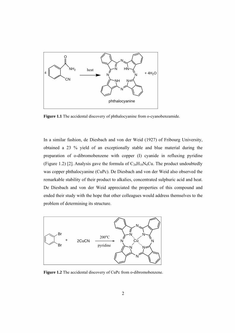
Figure 1.1 The accidental discovery of phthalocyanine from o-cyanobenzamide....... 2
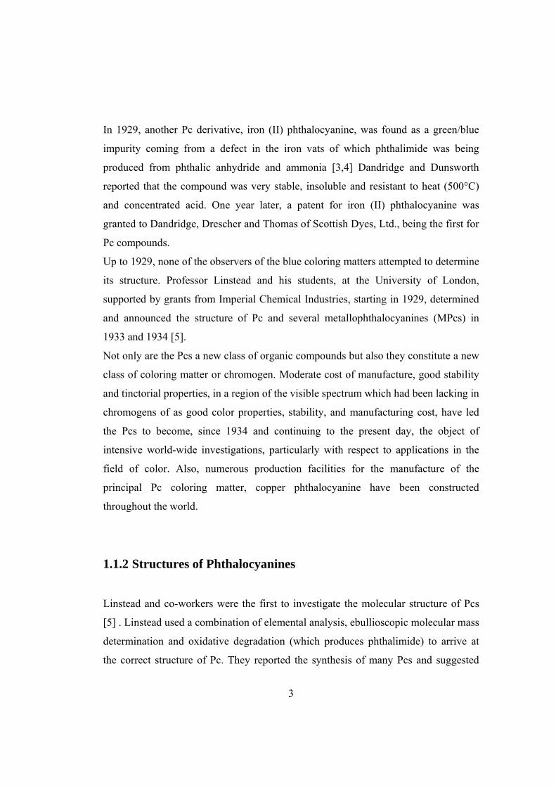
Figure 1.2 The accidental discovery of CuPc from o-dibromobenzene....................... 2
Figure 1.3 Structures of pyrrole, porphyrin, Pc and MPc ............................................ 4
Figure 1.4 Numbering in phthalocyanine molecule. .................................................... 5
Figure 1.5 Synthesis of phthalocyanines...................................................................... 7
Figure 1.6 Possible constitutional isomers of tetra-substituted Pcs ........................... 10
Figure 1.7 Structures of a) 1,4 and b) 2,3 -octa substituted Pcs................................ 11
Figure 1.8 Mechanism of phthalocyanine formation
in the presence of an alcohol [12]. .............................................................................. 13
Figure 1.9 Classic electronic absorption spectra of
a) Pc and b) MPc with B and Q bands ........................................................................ 16
Figure 1.10 Gouterman’s four model showing electron transitions and
the origin of Q and B bands for MPc .......................................................................... 17
Figure 1.11 Typical cyclic voltammogram for a reversible process .......................... 23
Figure 1.12 Structure of SNS-PN............................................................................... 28
Figure 1.13 Structures of H2SNS-Pc, ZnSNS-Pc and NiSNS-Pc .............................. 29
Figure 2.1 Schematic representation of a voltammetric cell ...................................... 32
Figure 2.2 Schematic representation of a spectroelectrochemical cell ...................... 34
Figure 2.3 Synthetic route of 4-aminophthalonitrile.................................................. 36
Figure 2.4 Synthetic route of 1,4-di(2-thienyl)-1,4-butanedione ............................... 37
Figure 2.5 Synthetic route of 4-(2,5-di-2-thienyl-1H-pyrrol-1-yl)phthalonitrile....... 37
Figure 2.6 Synthetic route of H2Pc-SNS, ZnPc-SNS and NiPc-SNS ........................ 39
Figure 3.1 Synthesis of all of the compounds ............................................................ 41
Figure 3.2 1H NMR spectrum of SNS-PN ................................................................. 43
Figure 3.3 13C NMR spectrum of SNS-PN ................................................................ 43

xv
Figure 3.4 FTIR spectra of (a) SNS-PN and (b) P(SNS-PN)..................................... 45
Figure 3.5 UV-vis spectra of 1.0 x 10⁻⁴ mol.L-1 for
H2Pc-SNS, ZnPc-SNS and NiPc-SNS in DCM .......................................................... 48
Figure 3.6 FTIR spectra of SNS-PN and H2Pc-SNS.................................................. 50
Figure 3.7 FTIR spectra of SNS-PN and ZnPc-SNS ................................................. 50
Figure 3.8 FTIR spectra of SNS-PN and NiPc-SNS.................................................. 51
Figure 3.9 FTIR spectra of H2Pc-SNS, ZnPc-SNS and NiPc-SNS............................ 52
Figure 3.10 FTIR spectra of H2Pc-SNS and P(H2Pc-SNS)........................................ 53
Figure 3.11 FTIR spectra of ZnPc-SNS and P(ZnPc-SNS) ....................................... 54
Figure 3.12 FTIR spectra of Pc-SNS and P(NiPc-SNS) ............................................ 54
Figure 3.13 Cyclic voltammogram of H2Pc-SNS on a Pt disc electrode at
100 mVs-1 in 0.1 M TBAP / DCM.............................................................................. 57
Figure 3.14 DPV of H2Pc-SNS in 0.1 M TBAP/DCM.............................................. 57
Figure 3.15 Cyclic voltammogram of ZnPc-SNS on a Pt disc electrode at
100 mVs-1 in 0.1 M TBAP/DCM................................................................................ 58
Figure 3.16 DPV of ZnPc-SNS in 0.1 M TBAP/DCM.............................................. 58
Figure 3.17 Cyclic voltammogram of NiPc-SNS on a Pt disc electrode at
100 mVs-1 in 0.1 M TBAP / DCM.............................................................................. 59
Figure 3.18 DPV of NiPc-SNS in 0.1 M TBAP/DCM .............................................. 59
Figure 3.19 Repeated scan electrochemical polymerization of
2.0 x 10⁻³ M SNS-PN .................................................................................................. 60
Figure 3.20 Cyclic voltammogram of P(SNS-PN) film on a Pt disc electrode at
100 mV/s in acetonitrile solution containing 0.2 M LiClO4. ...................................... 61
Figure 3.21 Cyclic voltammogram of P(SNS-PN) film (25 mC/cm2) on
a Pt disc electrode in acetonitrile containing 0.2 M LiClO4, NaClO4, and TBAP...... 62
Figure 3.22 Repeated potential scan electropolymerization of
0.1 mM H2Pc-SNS on a Pt disc electrode at 100 mVs-1 in 0.1 M TBAP/DCM ......... 64
Figure 3.23 Repeated potential scan electropolymerization of
0.1 mM ZnPc-SNS on a Pt disc electrode at 100 mVs-1 in 0.1 M TBAP/DCM ......... 64
xvi
Figure 3.24 Repeated potential scan electropolymerization of
0.1 mM NiPc-SNS on a Pt disc electrode at 100 mVs-1 in 0.1 M TBAP/DCM ......... 65
Figure 3.25 Scan rate dependence of P(H2Pc-SNS ) films (25 cycle)
on a Pt disc electrode in 0.1M TBAP/DCM at different scan rates
between 20 mV/s and 100 mV/s ................................................................................. 66
Figure 3.26 Scan rate dependence of P(ZnPc-SNS ) film (25 cycle)
on a Pt disc electrode in 0.1M TBAP/DCM at different scan rates
between 20 mV/s and 100 mV/s. ................................................................................ 66
Figure 3.27 Scan rate dependence of P(NiPc-SNS ) film (25 cycle) .............................
on a Pt disc electrode in 0.1M TBAP/DCM at different scan rates
between 20 mV/s and 100 mV/s. ................................................................................ 67
Figure 3.28 Relationship of anodic (Iac) and cathodic (Icc) current peaks
as a function of scan rate for neutral and oxidized H2Pc-SNS in
0.1 M TBAP/DCM...................................................................................................... 68
Figure 3.29 Relationship of anodic (Iac) and cathodic (Icc) current peaks
as a function of scan rate for neutral and oxidized ZnPc-SNS in
0.1 M TBAP/DCM...................................................................................................... 69
Figure 3.30 Relationship of anodic (Iac) and cathodic (Icc) current peaks
as a function of scan rate for neutral and oxidized NiPc-SNS in
0.1 M TBAP / DCM.................................................................................................... 69
Figure 3.31 Cyclic voltammogram of P(H2Pc-SNS) film (10 cycle)
on a Pt disc electrode in DCM containing 0.1 M zinc (II) acetate and TBAP ........... 70
Figure 3.32 In-situ absorption spectra of P(SNS-PN) (55 mC/cm2)
recorded in acetonitrile containing 0.2 M LiClO4 at various applied potentials. ........ 72
Figure 3.33 Electronic absorption spectra of P(H2Pc-SNS) (25 mC/ cm2) on ITO in
0.1 M TBAP/DCM solution during anodic oxidation of the polymer film ................ 74
Figure 3.34 Electronic absorption spectra of P(ZnPc-SNS) (25 mC/ cm2) on ITO in
0.1 M TBAP/DCM solution during anodic oxidation of the polymer film. ............... 75
Figure 3.35 Electronic absorption spectra of P(NiPc-SNS) (25 mC/ cm2)
xvii
on ITO in 0.1 M TBAP/DCM solution during anodic oxidation
of the polymer film. .................................................................................................... 76
Figure 3.36 Absorption and emission spectra of P(SNS-PN) in DMSO ................... 81
Figure 3.37 Emission spectra of P(SNS-PN) recorded in the presence of
3.3x10⁻⁵ M LiClO4 and NaClO4 in DMF .................................................................... 82
Figure 3.38 Emission spectra of P(ZnPc-SNS) (excited at 370 nm) in
(a) DMSO and (b) toluene .......................................................................................... 83
Figure 3.39 SEM micrographs of solution side of (a) P(H2Pc-SNS)
(b) P(ZnPc-SNS) and (c) P(NiPc-SNS) ...................................................................... 84
xviii
LIST OF TABLES TABLES
Table 3.1 Elemental analysis data for SNS-PN.......................................................... 45
Table 3.2 Elemental analysis data for Pc complexes ................................................. 46
Table 3.3 Summary of redox potentials (E1/2 vs Ag/AgCl) of the Pc complexes
in 0.1 M TBAP dissolved in DCM ............................................................................ 56
Table 3.4 Voltammetric and spectroelectrochemical data for P(SNS-PN)
recorded in AN containing 0.1 M LiClO4................................................................... 78
Table 3.5 Voltammetric and spectroelectrochemical data for P(H2Pc-SNS)
recorded in DCM containing 0.1 M TBAP................................................................. 79
Table 3.6 Voltammetric and spectroelectrochemical data for P(ZnPc-SNS)
recorded in DCM containing 0.1 M TBAP................................................................. 79
Table 3.7 Voltammetric and spectroelectrochemical data for P(NiPc-SNS)
recorded in DCM containing 0.1 M TBAP................................................................. 80
xix
ABBREVIATIONS Ag/AgCl Silver/silver chloride
AN Acetonitrile
CE Coloration efficiency
CV Cyclic voltammetry
DBN 1,5-Diazabicyclo[4.3.0]non-5-ene
DBU 1,8-Diazabicyclo[5.4.0]undec-7-ene
DCM Dichloromethane
DMF Dimethylformamide
DMAE N,N-dimethylaminoethanol
DMSO Dimethylsulfoxide
DPV Differential pulse voltammetry
Eg Band gap
Epa Anodic peak potential
Epc Cathodic peak potential
EQCM Electrochemical quartz crystal microbalance
FTIR Fourier transform infrared spectroscopy
H2Pc Metal-free phthalocyanine
H2Pc-SNS Tetrakis(4-(2,5-di-2-thiophen-2-yl-pyrrol-1-yl)) phthalocyanine
HOMO Highest occupied molecular orbital
Ipa Anodic peak current
Ipc Cathodic peak current
IR Infrared
ITO Indium-tin oxide
LiClO4 Lithium perchlorate
LUMO Lowest unoccupied molecular orbital
MPc Metallophthalocyanine
xx
NaClO4 Sodium perchlorate
NiPc-SNS Tetrakis(4-(2,5-di-2-thiophen-2-yl-pyrrol-1-yl)) phthalocyaninato
nickel
NMR Nuclear magnetic resonance spectroscopy
OTTLE Optically transparent thin layer electrode
Pc Phthalocyanine
PDT Photodynamic therapy
P(SNS-PN) Poly((2,5-di-2-thiophen-2-yl-pyrrol-1-yl)-phthalonitrile)
PTSA p-toluene sulfonic acid
SCE Saturated calomel electrode
SEM Scanning electron microscopy
SNS-PN 4-(2,5-di-2-thiophen-2-yl-pyrrol-1-yl)-phthalonitrile
SOOS 1,4-di(2-thienyl)-1,4-butadione
SPEL Spectroelectrochemical
TBAP Tetrabutylammonium perchlorate
UV Ultraviolet
vis Visible
ZnPc-SNS Tetrakis(4-(2,5-di-2-thiophen-2-yl-pyrrol-1-yl)) phthalocyaninato
zinc
1
CHAPTER 1
1 INTRODUCTION
1.1 Phthalocyanines
1.1.1 History of Phthalocyanines
The word phthalocyanine is derived from the Greek terms for naphtha (rock oil) and
for cyanine (dark blue). Naphtha was mentioned in ancient Greek literature.
Dioscorides stated naphtha to be a clear, combustible rock oil procured from
Babylonian asphalt. Cyanine was in the written vocabulary of several ancient Greek
writers, including Homer. The phthalocyanines (Pcs) (Figure 1.1) were discovered by
chance. In 1907, Braun and Tscherniac [1], at the South Metropolitan Gas Company
in London, upon examining the properties of o-cyanobenzamide which they made
from the reaction of phthalimide and acetic anhydride, found a trace amount of a blue
substance after heating o-cyanobenzamide, cooling, dissolving in alcohol, and
filtration. This substance undoubtedly was phthalocyanine.
2
O
NH2
CN
4heat
NN
N
NHN
N
N
HN
phthalocyanine
+ 4H2O
Figure 1.1 The accidental discovery of phthalocyanine from o-cyanobenzamide.
In a similar fashion, de Diesbach and von der Weid (1927) of Fribourg University,
obtained a 23 % yield of an exceptionally stable and blue material during the
preparation of o-dibromobenzene with copper (I) cyanide in refluxing pyridine
(Figure 1.2) [2]. Analysis gave the formula of C26H18N6Cu. The product undoubtedly
was copper phthalocyanine (CuPc). De Diesbach and von der Weid also observed the
remarkable stability of their product to alkalies, concentrated sulphuric acid and heat.
De Diesbach and von der Weid appreciated the properties of this compound and
ended their study with the hope that other colleagues would address themselves to the
problem of determining its structure.
Br
Br+ 2CuCN
200oCN
N
N
NN
N
N
N
pyridineCu
Figure 1.2 The accidental discovery of CuPc from o-dibromobenzene.
3
In 1929, another Pc derivative, iron (II) phthalocyanine, was found as a green/blue
impurity coming from a defect in the iron vats of which phthalimide was being
produced from phthalic anhydride and ammonia [3,4] Dandridge and Dunsworth
reported that the compound was very stable, insoluble and resistant to heat (500°C)
and concentrated acid. One year later, a patent for iron (II) phthalocyanine was
granted to Dandridge, Drescher and Thomas of Scottish Dyes, Ltd., being the first for
Pc compounds.
Up to 1929, none of the observers of the blue coloring matters attempted to determine
its structure. Professor Linstead and his students, at the University of London,
supported by grants from Imperial Chemical Industries, starting in 1929, determined
and announced the structure of Pc and several metallophthalocyanines (MPcs) in
1933 and 1934 [5].
Not only are the Pcs a new class of organic compounds but also they constitute a new
class of coloring matter or chromogen. Moderate cost of manufacture, good stability
and tinctorial properties, in a region of the visible spectrum which had been lacking in
chromogens of as good color properties, stability, and manufacturing cost, have led
the Pcs to become, since 1934 and continuing to the present day, the object of
intensive world-wide investigations, particularly with respect to applications in the
field of color. Also, numerous production facilities for the manufacture of the
principal Pc coloring matter, copper phthalocyanine have been constructed
throughout the world.
1.1.2 Structures of Phthalocyanines
Linstead and co-workers were the first to investigate the molecular structure of Pcs
[5] . Linstead used a combination of elemental analysis, ebullioscopic molecular mass
determination and oxidative degradation (which produces phthalimide) to arrive at
the correct structure of Pc. They reported the synthesis of many Pcs and suggested
4
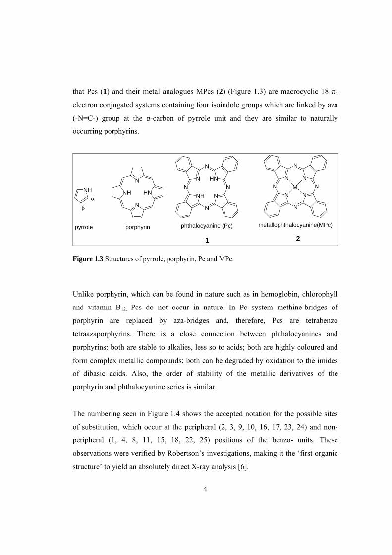
that Pcs (1) and their metal analogues MPcs (2) (Figure 1.3) are macrocyclic 18 π-
electron conjugated systems containing four isoindole groups which are linked by aza
(-N=C-) group at the α-carbon of pyrrole unit and they are similar to naturally
occurring porphyrins.
NN
N
NHN
N
N
HN
phthalocyanine (Pc)
NHα
β
pyrrole
NN
N
NN
N
N
N
metallophthalocyanine(MPc)
MHN
N
NH
N
porphyrin
1 2 Figure 1.3 Structures of pyrrole, porphyrin, Pc and MPc.
Unlike porphyrin, which can be found in nature such as in hemoglobin, chlorophyll
and vitamin B12, Pcs do not occur in nature. In Pc system methine-bridges of
porphyrin are replaced by aza-bridges and, therefore, Pcs are tetrabenzo
tetraazaporphyrins. There is a close connection between phthalocyanines and
porphyrins: both are stable to alkalies, less so to acids; both are highly coloured and
form complex metallic compounds; both can be degraded by oxidation to the imides
of dibasic acids. Also, the order of stability of the metallic derivatives of the
porphyrin and phthalocyanine series is similar.
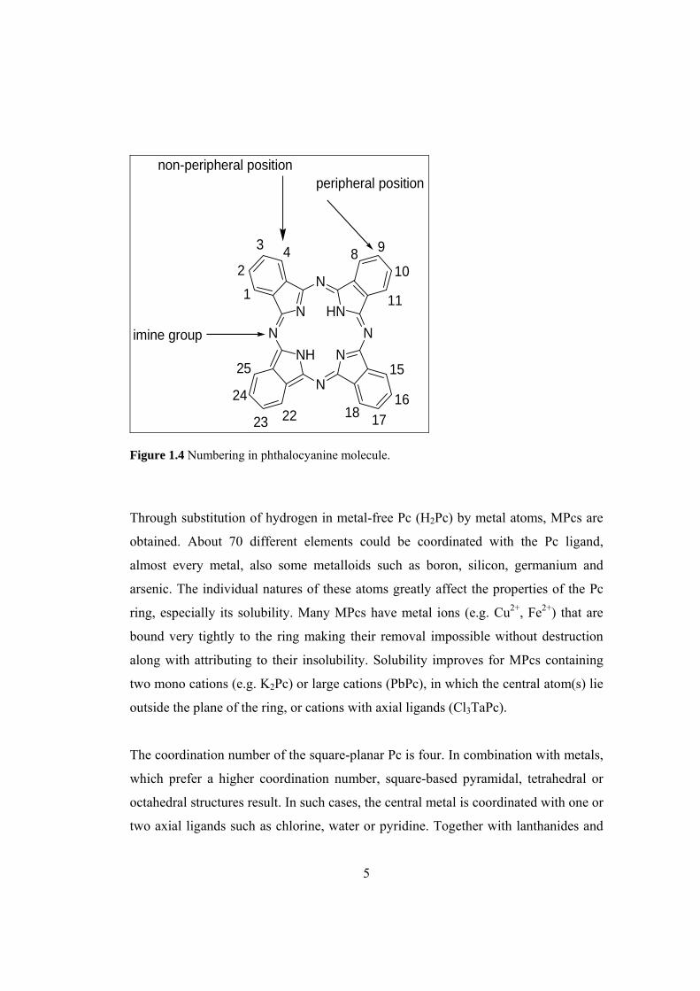
The numbering seen in Figure 1.4 shows the accepted notation for the possible sites
of substitution, which occur at the peripheral (2, 3, 9, 10, 16, 17, 23, 24) and non-
peripheral (1, 4, 8, 11, 15, 18, 22, 25) positions of the benzo- units. These
observations were verified by Robertson’s investigations, making it the ‘first organic
structure’ to yield an absolutely direct X-ray analysis [6].
5
NN
N
NHN
N
N
HN1
2
3 4 8 9
10
11
15
1617182223
24
25
peripheral positionnon-peripheral position
imine group
Figure 1.4 Numbering in phthalocyanine molecule.
Through substitution of hydrogen in metal-free Pc (H2Pc) by metal atoms, MPcs are
obtained. About 70 different elements could be coordinated with the Pc ligand,
almost every metal, also some metalloids such as boron, silicon, germanium and
arsenic. The individual natures of these atoms greatly affect the properties of the Pc
ring, especially its solubility. Many MPcs have metal ions (e.g. Cu2+, Fe2+) that are
bound very tightly to the ring making their removal impossible without destruction
along with attributing to their insolubility. Solubility improves for MPcs containing
two mono cations (e.g. K2Pc) or large cations (PbPc), in which the central atom(s) lie
outside the plane of the ring, or cations with axial ligands (Cl3TaPc).
The coordination number of the square-planar Pc is four. In combination with metals,
which prefer a higher coordination number, square-based pyramidal, tetrahedral or
octahedral structures result. In such cases, the central metal is coordinated with one or
two axial ligands such as chlorine, water or pyridine. Together with lanthanides and

6
actinides, complexes of a sandwich structure formed by two Pcs and one central
metal with eight coordinated nitrogen atoms result [7].
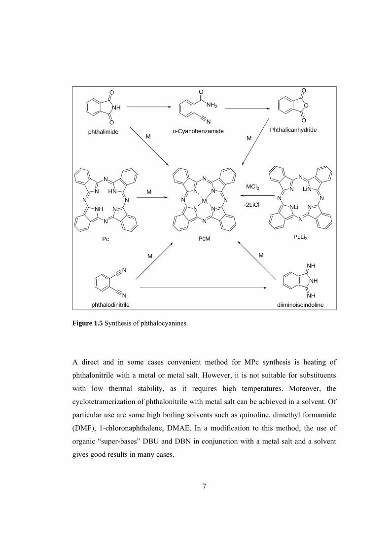
1.1.3 Synthesis of Phthalocyanines
Synthesis of Pcs can be achieved using different routes depending on the type of Pcs
to be synthesized; metal free, symmetrical and asymmetrical MPcs (Figure 1.5). Pcs
have been commonly synthesized by cyclotetramerization reaction of phthalyl
derivatives, namely, phthalic acid, phthalic anhydride, phthalimide, phthalonitrile,
and 1,2-dibromobenzene or 1,3-diiminoisoindoline [8]. A fairly mild, clean and direct
method for metal-free phthalocyanine (H2Pc) synthesis involves heating of
phthalonitrile with a base (1,8-diazabicyclo[5.4.0]undec-7-ene (DBU), 1,5-
diazabicyclo[4.3.0]non-5-ene (DBN) or NH3) in a solvent (e.g. 1-pentanol) or use of
basic solvent N,N-dimethylaminoethanol (DMAE).
Of particular interest and value is the method in which lithium, sodium or magnesium
alkoxides are used in primary alcohols (usually n- or iso-pentan-1-ol) for the
cyclotetramerization. The metal ions are easily removed to give H2Pc by acidic or
aqueous work-up. Another approach involves reducing agent (usually inexpensive
hydroquinone) that is melted together with phthalonitrile. The cyclotetramerization of
1,3- diiminoisoindoline is usually performed in a refluxing DMAE.
7
O
O
NH
phthalimide
O
NH2
No-Cyanobenzamide
O
O
O
Phthalicanhydride
NN
N
NHN
N
N
HN
Pc
NN
N
NN
N
N
N
PcM
NN
N
NLiN
N
N
LiN
PcLi2
M
N
Nphthalodinitrile
NH
NH
NHdiiminoisoindoline
M M
M
MCl2M
M
-2LiCl
Figure 1.5 Synthesis of phthalocyanines.
A direct and in some cases convenient method for MPc synthesis is heating of
phthalonitrile with a metal or metal salt. However, it is not suitable for substituents
with low thermal stability, as it requires high temperatures. Moreover, the
cyclotetramerization of phthalonitrile with metal salt can be achieved in a solvent. Of
particular use are some high boiling solvents such as quinoline, dimethyl formamide
(DMF), 1-chloronaphthalene, DMAE. In a modification to this method, the use of
organic “super-bases” DBU and DBN in conjunction with a metal salt and a solvent
gives good results in many cases.
8
Phthalimide, phthalic anhydride and phthalic acid have been used successfully for
MPc synthesis. Of special interest is phthalic anhydride as a precursor, as most
commercial processes are based upon this compound. Such reactions are commonly
carried out in melted urea, which serves as a convenient source of nitrogen
(ammonia). In addition to the appropriate metal salt, ammonium molybdate is usually
added as a catalyst. Nitrobenzene has been used in some cases as a solvent. It is
accepted that phthalic acid is converted to phthalimide via phthalic anhydride under
the reaction conditions.
Diiminoisoindoline, prepared from the reaction of phthalonitrile and ammonia in the
presence of catalytic amount of sodium methoxide, proved to be an excellent
precursor for metal-containing phthalocyanines. It has been widely used for silicon
and germanium phthalocyanine preparation. It is common to obtain some copper(II)
phthalocyanine directly from 1,2- dibromobenzene. This reaction involves heating the
dibromide with CuCN in a solvent, usually DMF or quinoline.
Historically, the eldest method for phthalocyanine synthesis is the reaction of 2-
cyanobenzamide in the presence of metal or metal salt in a bulk reaction or in a
solution. However, this method is limited to very few cases and has not received
much attention in daily lab practice. The complexation of metal-free phthalocyanine
is usually a clean and efficient reaction.
Additionally, subphthalocyanines can undergo ring expansion reaction to yield
unsymmetrical phthalocyanines. Nearly every metal from the periodic system can
replace two hydrogen atoms in the centre of the macrocycle. Moreover, the axial
substituents can be attached to many metals. Additionally, multinuclear structures can
be formed either through metal or through peripheral substituents. And finally, there
are sixteen positions on the periphery that can be replaced by many substituents.
Taking into account all these facts, today it is possible to prepare bespoken
9
phthalocyanine derivatives with highly tailored properties (e.g. Q-band position,
solubility, light absorption, self-assembling, etc.). There are two excellent reviews on
phthalocyanines preparation; one by Leznoff et al. [9] and the other, actually the most
up-to-date, by Neil B. McKeown [10]. Pc and related compounds synthesis has been
rapidly developing field with yearly appearing new achievements and publications.
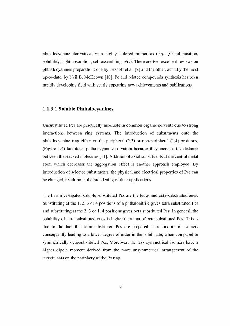
1.1.3.1 Soluble Phthalocyanines
Unsubstituted Pcs are practically insoluble in common organic solvents due to strong
interactions between ring systems. The introduction of substituents onto the
phthalocyanine ring either on the peripheral (2,3) or non-peripheral (1,4) positions,
(Figure 1.4) facilitates phthalocyanine solvation because they increase the distance
between the stacked molecules [11]. Addition of axial substituents at the central metal
atom which decreases the aggregation effect is another approach employed. By
introduction of selected substituents, the physical and electrical properties of Pcs can
be changed, resulting in the broadening of their applications.
The best investigated soluble substituted Pcs are the tetra- and octa-substituted ones.
Substituting at the 1, 2, 3 or 4 positions of a phthalonitrile gives tetra substituted Pcs
and substituting at the 2, 3 or 1, 4 positions gives octa substituted Pcs. In general, the
solubility of tetra-substituted ones is higher than that of octa-substituted Pcs. This is
due to the fact that tetra-substituted Pcs are prepared as a mixture of isomers
consequently leading to a lower degree of order in the solid state, when compared to
symmetrically octa-substituted Pcs. Moreover, the less symmetrical isomers have a
higher dipole moment derived from the more unsymmetrical arrangement of the
substituents on the periphery of the Pc ring.
10
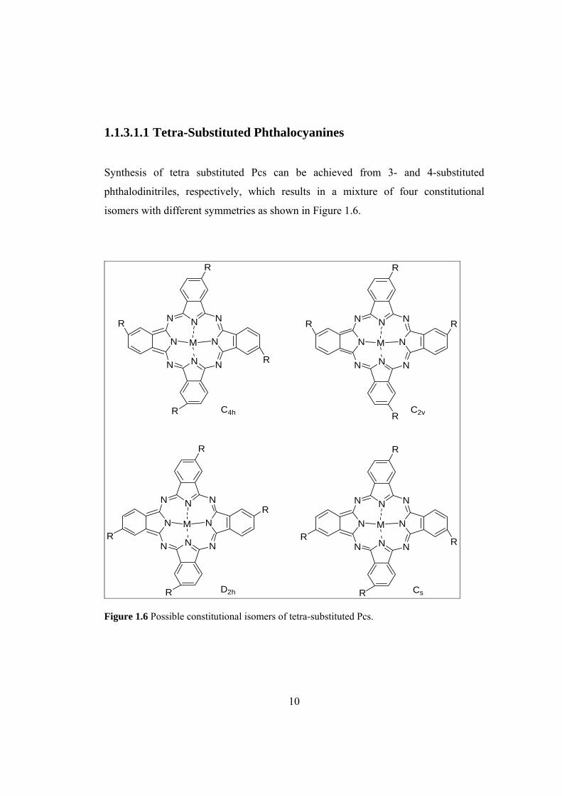
1.1.3.1.1 Tetra-Substituted Phthalocyanines
Synthesis of tetra substituted Pcs can be achieved from 3- and 4-substituted
phthalodinitriles, respectively, which results in a mixture of four constitutional
isomers with different symmetries as shown in Figure 1.6.
NNN
N
N N N
NM
R
R
R
R
NNN
N
N N N
NM
R
R
NNN
N
N N N
NM
R
R
NNN
N
N N N
NM
R
R
R
R
R
R
R
R
C4h C2v
D2h Cs Figure 1.6 Possible constitutional isomers of tetra-substituted Pcs.
11
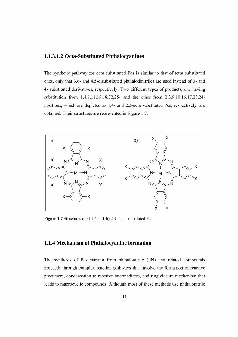
1.1.3.1.2 Octa-Substituted Phthalocyanines
The synthetic pathway for octa substituted Pcs is similar to that of tetra substituted
ones, only that 3,6- and 4,5-disubstituted phthalodinitriles are used instead of 3- and
4- substituted derivatives, respectively. Two different types of products, one having
substitution from 1,4,8,11,15,18,22,25- and the other from 2,3,9,10,16,17,23,24-
positions, which are depicted as 1,4- and 2,3-octa substituted Pcs, respectively, are
obtained. Their structures are represented in Figure 1.7.
NNN
N
N N N
NM
NNN
N
N N N
NM
X X
X
X
XX
X
X
X X
X
X
XX
X
X
a) b)
Figure 1.7 Structures of a) 1,4 and b) 2,3 -octa substituted Pcs.
1.1.4 Mechanism of Phthalocyanine formation
The synthesis of Pcs starting from phthalonitrile (PN) and related compounds
proceeds through complex reaction pathways that involve the formation of reactive
precursors, condensation to reactive intermediates, and ring-closure mechanism that
leads to macrocyclic compounds. Although most of these methods use phthalonitrile

12
as starting material, the reaction conditions are fairly different and therefore they do
not necessarily occur through identical mechanisms or intermediates. A detailed
comprehension of the mechanism is difficult to achieve because of the reaction
conditions employed in the synthesis of these compounds. In some synthetic routes,
intermediates have been isolated, thus facilitating the understanding of the
mechanism.
There are generally different suggested mechanisms for the Pc formation depending
on the starting materials and the reaction promoters [12].
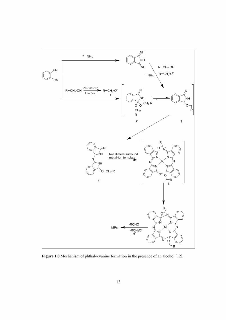
In presence of an alcohol, firstly, some basic promoters such as DBU or DBN
deprotonate the alcohol forming strong nucleophillic alkoxide species 1. These
species then attack the nitrile or the imide linkage in case of phthalonitrile and
diiminoisoindoline, respectively. The intermediates 2 and 3 are formed which are
suggested to condense or add further phthalonitrile in a template reaction forming the
intermediate 4. Metal-ion template is surrounded by the two dimers of 4 to form the
tetramer intermediate 5 which losses aldehyde and a hydride equivalent driven by the
aromatization of the formed phthalocyanine molecule.
The template effect of the central metal ion and the resulting stabilization this
complex causes, seem to be the driving force for the Pc macrocycle formation. The
same mechanism is also suggested for the reactions, which involve the use of Li or
Na. In this case the metal serves as electron donor for the template cyclization
according to the following equation:
4PN + 2e- → Pc2-
The Pc synthesis in presence of an alcohol is illustrated in Figure 1.8.
13
R CH2 OHDBU or DBN
Li or NaR CH2 O
1
CN
CN
NH3NH
NH
NH
+
NH
N
O OCH2R
CH2 RNH
N
O
R CH2 OH
R CH2 O
2 3
NH
N
NHN
O CH2 R
NH3-
two dimers surroundmetal-ion template N
NN
N
N
NN
N
R
O
O
M
N
NN
N
N
NN
N
R
O
O
M-RCHO
-RCH2O-
-H+
MPc
45
R
R
R Figure 1.8 Mechanism of phthalocyanine formation in the presence of an alcohol [12].

14
The high temperature reactions of phthalonitrile with a metal or a metal salt, either
neat or in a high boiling solvent, are likely to proceed by a similar mechanism to that
shown in Figure 1.8.
1.1.5 Application of Phthalocyanines
Pcs and MPcs have been a subject of extensive study for many years in much detail
because of their increasing diverse applications from industrial to biomedical.
• Owing to beautiful color, usually blue or green, considerable chemical and
photochemical stability, Pcs are used worldwide as dyestuffs. They are an important
industrial commodity. They are widely used in inks (ballpoint pens, printing inks
etc.), coloring for plastics and metal surfaces as well as dyestuff for jeans and other
clothing. Interestingly, copper phthalocyanine was certified as a food dyestuff in
Germany and for coloring contact lenses in the United States [9].
• Photodynamic therapy (PDT) uses a combination of a photosensitizing drug
(dye) and light in the presence of molecular oxygen to obtain a therapeutic effect that
depends on selective cell injury. PDT has been developed as an alternative to
conventional treatments such as radiotherapy and chemotherapy. The photosensitizer
is harmless unless it is activated by light. Light can be therefore selectively focused
on the tumor through an optical fiber, followed by the photosensitizer activation and
cell destruction afforded in a predetermined area. Among the second-generation
photosensitizers developed for PDT, the phthalocyanines have received particular
attention due to their high molar absorption coefficient (ε ca. 105 M-1*cm-1) in the red
part of the spectrum (640- 710 nm), which allows increased tissue penetration of the
activating light. Low toxicity of Pcs makes them promising for PDT application. Both
lipophilic and water-soluble Pcs have been considered as candidates for PDT [13-15].
15
• Due to the narrow bandwidth, excellent thermal, chemical as well as
photochemical stability and compatibility with semiconductor diode lasers, Pcs have
been successfully applied as a laser-optical recording media. They are particularly
attractive candidates for applications in long-term optical data storage (i.e. write once
read many times (WORM) discs) [16].
• The phenomena of electrochromism relays on the reversible color change of the
material upon application of an electric field. Many Pcs are famous for their
electrochromic properties. Films of dyes can be switched over many colors which
make them useful for display devices construction [17].
• Besides, Pcs find uses in the petroleum industry as catalysts in sulphur
compounds oxidation (Merox process) [18-22].
• MPcs have several potential technological applications, including energy
conversion [23-25], liquid crystal displays [26,27], gas sensing [9,28] and
electrocatalysis in fuel cells [29,30]. Moreover, MPcs are widely used as
photoconductors in the printer and photocopier industry [31,32] as well as non-linear
optical devices [33-35].
1.2 Chemistry of Phthalocyanines
1.2.1 Spectral Properties
1.2.1.1 Absorption Spectra of Phthalocyanines
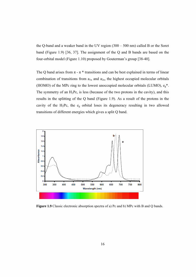
The main and most characteristic feature of the absorption spectra of Pcs is the
presence of very intensive two bands; one in the visible region (600 – 800 nm) called
16
the Q-band and a weaker band in the UV region (300 – 500 nm) called B or the Soret
band (Figure 1.9) [36, 37]. The assignment of the Q and B bands are based on the
four-orbital model (Figure 1.10) proposed by Gouterman’s group [38-40].
The Q band arises from π - π * transitions and can be best explained in terms of linear
combination of transitions from a1u and a2u, the highest occupied molecular orbitals
(HOMO) of the MPc ring to the lowest unoccupied molecular orbitals (LUMO), eg*.
The symmetry of an H2Pc, is less (because of the two protons in the cavity), and this
results in the splitting of the Q band (Figure 1.9). As a result of the protons in the
cavity of the H2Pc, the eg orbital loses its degeneracy resulting in two allowed
transitions of different energies which gives a split Q band.
Figure 1.9 Classic electronic absorption spectra of a) Pc and b) MPc with B and Q bands.

17
Figure 1.10 Gouterman’s four model showing electron transitions and the origin of Q and B bands for MPc.
1.2.1.2 Infrared Spectroscopy
The infrared (IR) spectra of MPc complexes are typically complex but similar. The
main bands are the C-H stretching vibration at around 3030 cm-1, C-C ring skeletal
stretching vibrations at around 1600 and 1475 cm-1 , C-H out of plane bending
vibrations at around 750-790 cm-1, all these bands are from the aromatic ring of the
MPc. The unmetallated Pcs can be distinguished from the metallated ones by the
presence of N-H stretching vibration at around 3298 cm-1 in the former but absence of
the band in the latter.
1.2.2 Electrochemistry of Phthalocyanines
The neutral form of Pc skeleton exists as a dianion, i.e. Pc-2 [41], which may be
reduced or oxidized. The electrochemical activity of unmetallated Pcs is related to
processes occurring on the ring; on the other hand, the MPcs containing electroactive

18
central metals exhibit electroactivity associated with the central metals, in addition to
ring processes. Examples of electroactive metals include cobalt, iron and manganese
while electrochemically inactive metals include zinc, nickel and magnesium.
Moreover, electroactive ligands substituted on the Pc also exhibit their own
characteristic redox peaks or couples [42].
The redox activity of Pcs is directly related to HOMO and LUMO in the molecule.
Oxidation is the removal of electron(s) from HOMO (a1u) while reduction is the
addition of electron(s) to the LUMO (Figure 1.10). Successive removal of up to two
electrons from HOMO (a1u) results in the formation of Pc(-1) and Pc(0). In the same
way, successive gain of one to four electrons by the LUMO of the Pc complex results
in the formation of Pc-3, Pc-4, Pc-5 and Pc-6 [43]. These processes can be monitored
with electrochemical methods such as amperometry and complexes are influenced by:
the nature of the substituents on the Pc ring; the nature and oxidation state of the
central metal; the nature of any axial ligands and solvents [44].
1.3 Phthalocyanine Polymers
Polymeric Pcs are prepared by two methods: polycyclotetramerization of
tetracarbonitriles and electropolymerization of suitably designed Pc monomer.
1.3.1 Polymeric Phthalocyanines by Cyclotetramerization Reactions
For polycyclotetramerization, bifunctional monomers based on tetracarbonitriles,
various oxy-, arylenedioxy-, and alkylenedioxy-bridged diphthalonitriles and other
19
nitriles or tetra carboxylic acid derivatives are employed mainly in the presence of
metal salts or metals in bulk at higher temperatures.
The polymers exhibit good thermal stability under an inert gas atmosphere up to ≈
500 oC and under oxidative conditions up to ≈ 350 oC. Low molecular weight
phthalocyanines can be purified depending on either being unsubstituted or
containing suitable substituents by zone sublimation or liquid chromatography.
Common instrumental techniques are employed for their analytical characterization.
In contrast, polymeric Pcs are not soluble in organic solvents (sometimes only
partially soluble in conc. sulphuric acid) and are not vaporizable. Therefore,
separation from unreacted monomers, metal salts and perhaps by-products is only
possible by treatment with organic solvents (e. g., in a Soxhlet apparatus) or dilute
acids. In the polycyclotetramerization of tetracarbonitriles, the formation of by-
products, such as polyisoindolenine and polytriazine can occur. They are covalently
incorporated into the polymers as co-units and cannot be separated from the Pc
structural elements [45, 46]. Hence, a structurally uniform formation of polymeric
Pcs is crucial.
For a complete characterization of the polymers, the following points must be
considered: structural uniformity, nature of end groups, metal content and degree of
polymerization (molecular weight). In very few reports only, sufficient statements
regarding these points are made and really structurally uniform polymers were
prepared [46]. It should be pointed out that the preparation of structurally uniform
polymeric Pc is restricted to well-defined reaction conditions. For various
investigations with respect to electrical, photoelectrical, catalytic and photocatalytic
properties, the preparation of thin films on flat surfaces (e.g., glass, Ti, glass/ITO
(indium-tin oxide), KCl) or coatings on particles (e.g., SiO2, TiO2, Al2O3) is
necessary. Since polymeric Pcs are insoluble and not vaporizable, special techniques
must be employed.
20
1.3.2 Polymeric Phthalocyanines by Electropolymerization
This method allows formation of polymer films when there exists a suitable
substituent in the peripheral benzene rings of Pc forming differently structured
polymeric films. Lots of work has been done on the study of mechanisms of polymer
formations from monomers containing groups such as amino, aniline, pyrrole and
thiophene [47-49].Factors such as solubility of monomer, nature of solvent, electrode
size and nature, and ability to form an insoluble polymer govern the polymer growth
mechanism. The mechanism of polymer growth of polypyrrole, polythiophene and
polyaniline has been studied using cyclic voltammetry, electrochemical quartz crystal
microbalance (EQCM) and spectroelectrochemical methods [50-53].
MPc complexes with ring substituents such as amino, pyrrole, sulphonate and
mercaptopyrimidine groups have been used to modify various electrodes as polymer
films for analytes such as glycine, chlorophenols, dopamine, Lcysteine, hydrazine
and oxygen.
1.3.2.1 The Electrochemical Polymerization Strategy
Electrochemical polymerization is an elegant, attractive and easy strategy for the
immobilization of metal complexes [54-59] on the surface of electrodes. The principle
is based on the electrochemical oxidation (or reduction) of a suitably designed
monomer to form a polymeric film incorporating the metal complex. Pyrrole-,
thiophene- and aniline-based monomers have been the most commonly used
materials [57-60]. Such chemically substituted monomers have many interesting
features, including a high flexibility in their molecular design.
21
Additionally, such materials offer the possibility of using either aqueous or organic
solutions to carry out the electropolymerization. The electrochemical deposition
process is controlled by the electrode potential. This can be achieved either by
controlled potential, controlled current electrolysis or cyclic voltammetry within a
well-defined potential range.
Growth of the polymeric films or more precisely, control of the amount of deposited
materials (or the polymer film thickness), can be easily achieved by monitoring the
total charge passed during the electrooxidative (or reductive) polymerization process.
In the general case, the mechanism of electropolymerization of such substituted
monomers has still not been completely explained, despite the large quantity of data
on this subject.
However, it is now well accepted that in the case of pyrrole and aniline derivatives,
the first step in the electropolymerization process is the electrooxidative formation of
a radical cation from the chosen monomer [57-60]. This oxidation reaction is
followed by a dimerization process, followed by further oxidation and coupling
reactions. This leads to the formation of oligomers and polymers on the electrode
surface. It also appears that the morphology and the physical properties of the
polymer films depend largely upon the electrochemical polymerization conditions.
Thus, one can induce a supplementary design parameter during the polymerization
step by adjusting the solution composition or the electrode potential.
In this way, electrochemical polymerization can be carefully controlled, resulting in
multilayered structures and copolymers from multicomponent solutions.
22
1.4 Electrochemical Basics
The electrochemical techniques taking place when an electric potential is applied to
the system under study give information on the processes.
1.4.1 Cyclic Voltammetry
Cyclic voltammetry is a kind of electrochemical measurement and used for studying
the redox properties of chemicals. The three-electrode method is the most widely
used because the potential of reference does not change easily during the
measurement. This method needs a reference electrode, working electrode, and
counter electrode. Electrolyte is added to the compound solution to ensure sufficient
conductivity. The combination of the solvent and the electrolyte determines the range
of the potential.
The most important electrode in cyclic voltammetry is the working electrode.
Electrochemical reactions being studied occur at the working electrode and polymer
coating is formed on it. The working electrode can be made from a variety of
materials including: platinum, gold, silver, glassy carbon, nickel and palladium.
Counter (auxiliary) electrode conducts the electricity from the signal source into the
solution, maintaining the correct current. It is usually inert conduct like platinum or
graphite. A reference electrode is used in measuring the working electrode potential.
A reference electrode should have a constant electrochemical potential as long as no
current flows through it. The potential that is cycled is the potential difference
between the working electrode and the reference electrode. It is usually made from
silver/silver chloride (Ag/AgCl) or saturated calomel electrode (SCE).

23
In this system, the potential of the electrode is cycled from a starting potential, Ei to a
final potential, Ef (the potential is also called the switching potential) and then back to
Ei, Figure 1.11. The potential at which the peak current occurs is known as the peak
potential, Ep (anodic peak potential (Epa), cathodic peak potential (Epc) ). At this
potential, redox species have been depleted at the electrode surface and the current is
diffusion limited. The magnitude of the Faradaic current, Ipa (anodic peak current) or
Ipc (cathodic peak current), is an indication of the rate at which electrons are being
transferred between the redox species and the electrode. Cyclic voltammetric
processes could be reversible, quasi-reversible and irreversible.
Figure 1.11 Typical cyclic voltammogram for a reversible process.

24
The voltammogram obtained provides us to understand the electroactivity and redox
potential of the material, mechanism of the electrochemical reactions, reversibility of
electron transfer, whether the reaction products are further reduced or oxidized. In the
case of the polymers, cyclic voltammetry gives basic information on the oxidation
potential of the monomers, on film growth, on the redox behavior of the polymer, and
on the surface concentration (charge consumed by the polymer).
Conclusions can also be drawn from the cyclic voltammograms regarding the rate of
charge transfer, charge transport processes, and the interactions that occur within the
polymer segments, at specific sites and between the polymer and the ions and solvent
molecules. For very thin films and/or at low scan rates, when the charge transfer at
the interfaces and charge transport processes within the film are fast, i.e.,
electrochemically reversible (equilibrium) behavior prevails, and if no specific
interactions (attractive or repulsive) occur between the redox species in the polymer
film.
1.4.2 Constant Potential Methods (Potentiostatic)
Potentiostatic method is conducted with a three-electrode system. The potential
between the working and reference electrodes is maintained by a potentiostat. An
electronic feedback circuit continually compares and controls the working electrode
potential with respect to the reference electrode. Several factors should be considered
in choosing the appropriate electrolysis potential, including the threshold reaction
potential determined by voltammetry, the potential at which interfering reactions may
occur and the desired rate of the electrochemical reaction.
The voltage between the working and the reference electrode may be called the
polymerization potential. By keeping the potential constant, creation of undesired

25
species is prevented; hence the initiation becomes selective, that is, through the
monomer itself. Chronoamperometry, i.e. measuring the current as a function of time,
is the method of choice to study the kinetic of polymerization and especially the first
steps.
1.4.3 Constant Current Methods (Galvanostatic)
Galvanostatic method is also named as Chronopotentimetry and carried out by
applying a constant current between the working and auxiliary electrodes using a
galvanostat. Only a simple, two-electrode configuration is required for galvanostatic
electrolysis. The galvanostat ensures a constant current density and thus a controlled
rate of the electrochemical reaction.
Common applications of the galvanostat include constant current stripping
potentiometry and constant current electrolysis. One advantage of all constant current
techniques is that the ohmic drop due to solution resistance is also constant, as it is
equal to the product of the current and the solution resistance. However, as the
reaction proceeds, the potential on the working electrode may change, new
electrochemical processes may occur at different potentials and a change in the
composition or character of the product may result and for that reason, complications
may arise in initiation and propagation steps.
1.4.4 Differential Pulse Voltammetry (DPV)
This technique is comparable to normal pulse voltammetry in that the applied
potentials are an overlapping of a fixed amplitude pulse and a linear potential ramp.
However, it differs from normal pulse voltammetry because each potential pulse is
26
fixed, of small amplitude (10 to 100 mV), and is superimposed on a slowly changing
base potential. Current is measured at two points for each pulse, the first point just
before the application of the pulse and the second at the end of the pulse. These
sampling points are selected to allow for the decay of the nonfaradaic (charging)
current. The difference between current measurements at these points for each pulse
is determined and plotted against the base potential.
1.4.5 Spectroelectrochemistry
Spectroelectrochemistry combines the use of electrochemistry and spectroscopy. A
particular electrochemical cell, called an OTTLE (Optically Transparent Thin Layer
Electrode) cell, holds the redox active compound, which is either oxidized or reduced.
Product formation is then monitored in situ by spectroscopic techniques providing
information about the material’s band gap and intraband states created upon doping
as well as give electrochromic properties of conducting polymers at various applied
potentials.
Several spectroscopic techniques have been combined with electrochemical methods.
UV/VIS/NIR spectrometries have become routine methods in investigations of
conducting polymer films, where they are used to monitor the chemical changes
occurring in the surface film [61-65]. In most experiments the transmission mode has
been applied. Optically transparent electrodes (OTEs) are usually employed, which
are either indium–tin oxide (ITO) or a very thin (less than 100 nm) layer of gold or
platinum on a glass or quartz substrate. Another type of electrode used is a partially
transparent metal grid or mesh. In some cases the simple grid electrode is replaced by
a LIGA structure (LIGA, or lithographic galvanic up-forming, is a technique based on
a synchrotron radiation patterned template); however, these systems can be used for
27
the detection of soluble species. The reflection mode is seldom used in UV/VIS
spectroelectrochemistry.
1.4.6 Electrochromism
The term electrochromism is analogous to thermochromism (change in color
produced by heat) and photochromism (change in color produced by light) [66] and
can be defined as the capability of a material to change its optical properties within
the whole electromagnetic spectrum under an applied voltage. Electrochromic
materials exhibit a change in absorbance, reflection, or transmission of
electromagnetic radiation induced by an electrochemical oxidation–reduction
reaction.
Most often, the color change is between a transmissive state and a colored state, but
many materials switch between multiple colored states and are referred to as
polyelectrochromic materials. Some of the most commonly studied electrochromic
materials include transition metal oxides (e.g., tungsten oxide, WO3) organic
molecules (e.g., viologens), and inorganic complexes (e.g., Prussian Blue [PB]) [67-
70]. With many of these materials, along with conducting polymers, the
electrochromic effect is reversible and can occur not only in the visible region but
also in the ultraviolet (UV), infrared (IR), and even microwave regions of the
spectrum [71-73]. Compared to other electrochromic materials polymers have some
potentially achievable advantages. These polymers offer better processability, faster
switching, and color tunability than their inorganic and molecular counterparts.
Conjugated polymers can be either anodically coloring (color upon oxidation) or
cathodically coloring (color upon reduction), and can exhibit multiple color states in
the same material. Through minimal structural modifications, these polymers can be
28
made soluble in common organic solvents, which allow straightforward preparation
of polymer films for large-scale applications.
1.5 Aim of the study
In our laboratory, the novel synthesis of diazophenylene and diazodiphenylene
bridged Co/Ni/Cu/Ce/Er Pc polymers were performed by Cemil Alkan [74-76]. With
the help of the results of this study, it was aimed:
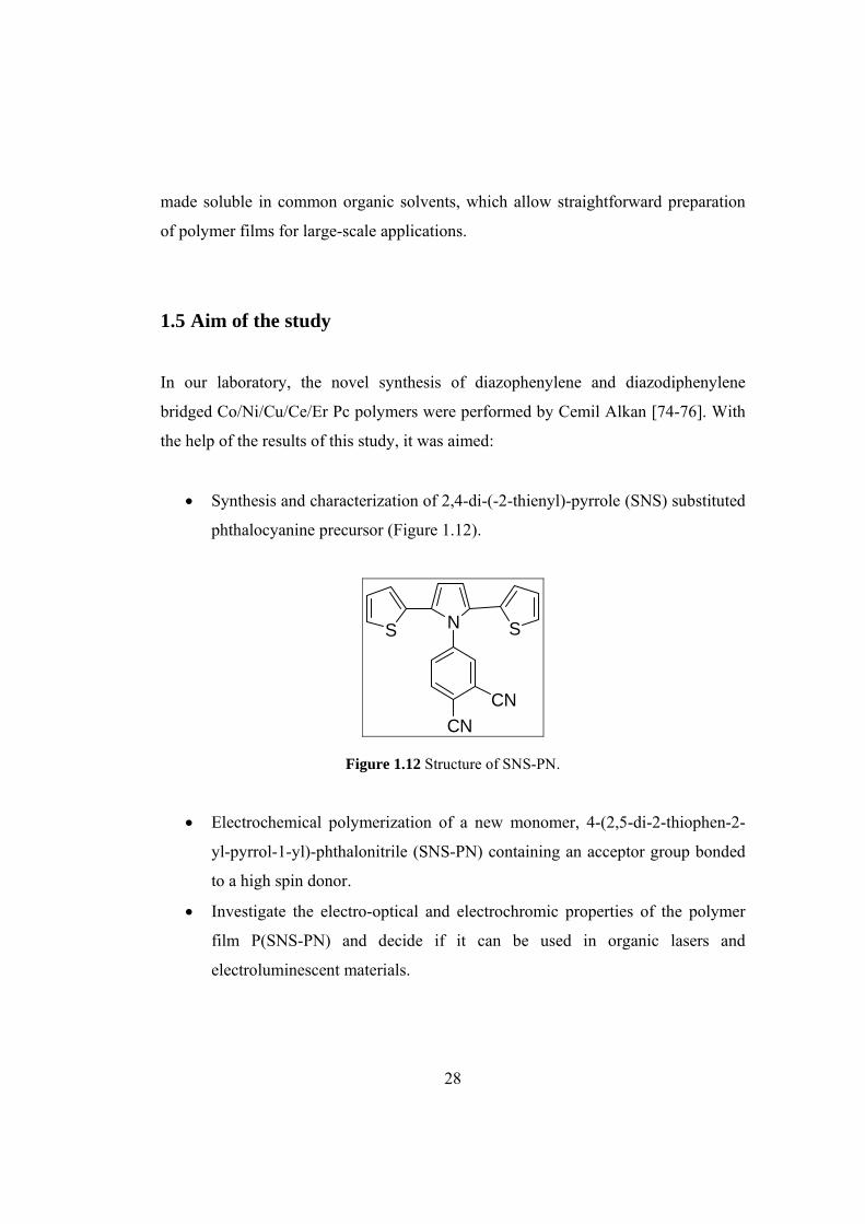
• Synthesis and characterization of 2,4-di-(-2-thienyl)-pyrrole (SNS) substituted
phthalocyanine precursor (Figure 1.12).
SS N
CNCN
Figure 1.12 Structure of SNS-PN.
• Electrochemical polymerization of a new monomer, 4-(2,5-di-2-thiophen-2-
yl-pyrrol-1-yl)-phthalonitrile (SNS-PN) containing an acceptor group bonded
to a high spin donor.
• Investigate the electro-optical and electrochromic properties of the polymer
film P(SNS-PN) and decide if it can be used in organic lasers and
electroluminescent materials.
29
• Study whether electron withdrawing cyanide groups of P(SNS-PN) can
interact with any metal cation through its nitrogen atoms and can be used as
cation sensing material.
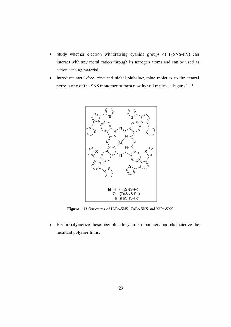
• Introduce metal-free, zinc and nickel phthalocyanine moieties to the central
pyrrole ring of the SNS monomer to form new hybrid materials Figure 1.13.
NN
N
NN
N
N
N
N
S
S
NS
S
N
S
S
NS
S
M
M: H (H2SNS-Pc) Zn (ZnSNS-Pc) Ni (NiSNS-Pc)
Figure 1.13 Structures of H2Pc-SNS, ZnPc-SNS and NiPc-SNS.
• Electropolymerize these new phthalocyanine monomers and characterize the
resultant polymer films.

30
CHAPTER 2
2 EXPERIMENTAL 2.1 Materials
AlCl3 (Aldrich), succinyl chloride (Aldrich), thiophene (Merck), p-toluenesulfonic
acid (PTSA) (Aldrich), 4-nitrophthalonitrile (Across), n-hexanol (Merck), n-pentanol
(Merck), 1,8-diazabicyclo[5.4.0]undec-7-ene (DBU) (Merck), zinc (II) acetate 2-
hydrate (Merck), nickel (II) chloride (Merck), ethanol (Riedel-de-Haen), methanol
(Merck), n-hexane (Merck), diethyl ether (Merck), dimethylsulfoxide (DMSO),
hydrochloric acid (HCl) (Merck), sodium hydrogencarbonate (NaHCO3) (Aldrich),
magnesium sulphate (MgSO4), lithium perchlorate (LiClO4) (Aldrich),
tetrabutylammonium perchlorate (TBAP), iron powder were used as received.
Acetonitrile (AN) (Merck), dichloromethane (DCM), and toluene were distilled
before use.
2.2 Instrumentation
2.2.1 Nuclear Magnetic Resonance (NMR) Spectrometer 1H NMR and 13C NMR spectra were recorded on a Bruker NMR Spectrometer (DPX-
400) in CDCl3 as the solvent and chemical shifts (δ) were given relative to
tetramethylsilane as the internal standard.

31
2.2.2 Fourier Transform Infrared (FTIR) Spectrometer
Fourier Transform Infrared spectroscopy (FTIR) spectra of the monomers and their
polymers were recorded with a Bruker Vertex 70 spectrophotometer.
2.2.3 Fluorescence Spectrophotometer
Fluorescence measurements were recorded on a Varian Cary Eclipse Fluorescence
Spectrophotometer.
2.2.4 Scanning Electron Microscopy
The scanning electron microscope (SEM) is a type of electron microscope capable of
producing high-resolution images of a sample surface. Due to the manner in which
the image is created, SEM images have a characteristic three-dimensional appearance
and are useful for judging the surface structure of the sample. The morphological
features of the polymer coated ITO electrodes were performed by using QUANTA
400F Field Emission scanning electron microscope.
2.2.5 Elemental Analyzer
Elemental determination of carbon, hydrogen, nitrogen, and sulfur were carried out
by LECO CHNS-93 elemental analyzer.

32
2.3 Electropolymerization and Characterization
2.3.1 Electropolymerization of SNS-PN
The polymers of SNS-PN were synthesized from an electrolytic medium containing
2.0 mM monomer and 0.2 M LiClO4 in acetonitrile via repetitive cycling at a scan
rate of 100 mV/s or constant potential electrolysis at 1.0 V vs Ag wire using Gamry
PCI4/300 potentiostat-galvanostat. The polymer was coated on platinum (0.02 cm2)
or indium-tin oxide (ITO, Delta Tech. 8–12 Ω, 0.7x5 cm) working electrode. The
resulting polymer films were washed with acetonitrile to remove LiClO4 and
unreacted monomers after the electrolysis.
Figure 2.1 Schematic representation of a voltammetric cell.
33
2.3.2 Electropolymerization of H2Pc-SNS, ZnPc-SNS and NiPc-SNS
Prior to electrochemical polymerization, redox behavior of the phthalocyanine
complexes (H2Pc-SNS, ZnPc-SNS and NiPc-SNS) were investigated using CV and
differential pulse voltammetry (DPV) in DCM solution containing 0.1 M TBAP on
platinum electrode.
The monomers were successfully electropolymerized via potentiodynamic or
potentiostatic methods using three-electrode system containing a platinum disc (0.02
cm2), a platinum wire as working and counter electrodes, respectively, as well as
Ag/AgCl electrode as a reference electrode. Electrochemical behavior of
corresponding polymer films, coated on working electrode was investigated in
monomer-free electrolytic medium after washing with DCM to remove the
oligomeric species and unreacted monomer.
All the solutions were degassed with N2 and measurements were performed at room
temperature under nitrogen atmosphere using Gamry PCI4/300 potentiostat-
galvanostat before electrochemical measurements.
2.3.3 Spectroelectrochemistry
Spectroelectrochemical (SPEL) measurements provide key properties of conjugated
polymers such as band gap (Eg), the intraband states created upon doping, as well as
give electrochromic properties at various applied potentials.
Experimentally, the band gap is related to the wavelength of the first absorption band
in the electronic spectrum of the substance. Thus, a photon with λ (wavelength) can

34
excite an electron from HOMO to LUMO level π →π* if the energy condition is
fulfilled.
ΔE = E(LUMO)-E(HOMO)
ΔE = hν=h(c/λ)
ΔE = The band gap (Energy gap)
For electro-optical studies, ITO electrodes were coated by the polymer films. Prior to
SPEL investigations, the polymer films were switched between their neutral and
doped states several times in order to equilibrate redox behavior in monomer-free
electrolytic solution. In-situ SPEL studies were performed using Hewlett–Packard
8453A diode array spectrometer. A Pt wire was used as a counter electrode and a Ag
wire as pseudo-reference electrode which was calibrated externally using 5 mM
solution of ferrocene/ferrocenium couple in the electrolytic solution.
Figure 2.2 Schematic representation of a spectroelectrochemical cell.

35
2.3.4 Switching Properties of Polymers
Electrochromic switching studies monitor the ability of a polymer to switch rapidly
and exhibit a striking color change. It is important for electrochromic applications of
the polymer films. For this aim, square wave potential step method was coupled with
optical spectroscopy to investigate the switching ability of P(SNS-PN), P(H2Pc-SNS),
P(ZnPc-SNS) and P(NiPc-SNS) between their neutral and oxidized states.
In this double potential step experiment, the potential was set at an initial potential for
a set period of time, and was stepped to a second potential for a set period of time,
before being switched back to the initial potential again. In order to study switching
properties of polymers, they were deposited on ITO-coated glass slides as in the form
of thin films.
After coating the polymers on ITO electrode, a potential square wave was applied in
the monomer free electrolyte solution while recording the percent transmittance
between its neutral and doped states at a fixed maximum absorption wavelength.
Switching properties of polymer films were investigated by application of potential
square wave technique with a residence time of 10 seconds between their oxidized
and reduced potential ranges.
2.4 Experimental Procedure
2.4.1 Synthesis of 4-aminophthalonitrile
Following the general procedure of Griffiths and Roozpeikar [77] a suspension of 4-
nitrophthalonitrile (3.89 g, 22.5 mmol) in a mixture of methanol (80 mL) and
concentrated hydrochloric acid (17.5 mL) was heated to reflux. Iron powder (4.0 g,
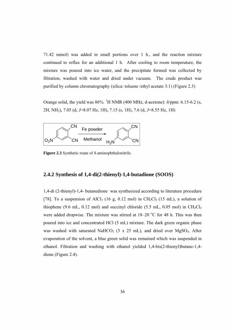
36
71.42 mmol) was added in small portions over 1 h., and the reaction mixture
continued to reflux for an additional 1 h. After cooling to room temperature, the
mixture was poured into ice water, and the precipitate formed was collected by
filtration, washed with water and dried under vacuum. The crude product was
purified by column chromatography (silica: toluene /ethyl acetate 3:1) (Figure 2.3)
Orange solid, the yield was 86%. 1H NMR (400 MHz, d-acetone): δ/ppm: 6.15-6.2 (s,
2H, NH2), 7.05 (d, J=8.07 Hz, 1H), 7.15 (s, 1H), 7.6 (d, J=8.55 Hz, 1H)
CN
CNO2N H2N
CN
CN
Fe powder
Methanol
Figure 2.3 Synthetic route of 4-aminophthalonitrile.
2.4.2 Synthesis of 1,4-di(2-thienyl)-1,4-butadione (SOOS)
1,4-di (2-thienyl)-1,4- butanedione was synthesized according to literature procedure
[78]. To a suspension of AlCl3 (16 g, 0.12 mol) in CH2Cl2 (15 mL), a solution of
thiophene (9.6 mL, 0.12 mol) and succinyl chloride (5.5 mL, 0.05 mol) in CH2Cl2
were added dropwise. The mixture was stirred at 18–20 oC for 48 h. This was then
poured into ice and concentrated HCl (5 mL) mixture. The dark green organic phase
was washed with saturated NaHCO3 (3 x 25 mL), and dried over MgSO4. After
evaporation of the solvent, a blue green solid was remained which was suspended in
ethanol. Filtration and washing with ethanol yielded 1,4-bis(2-thienyl)butane-1,4-
dione (Figure 2.4).

37
SCl
ClO
O+
O SS O
AlCl3
CH2Cl218-20oC
Figure 2.4 Synthetic route of 1,4-di(2-thienyl)-1,4-butanedione.
2.4.3 Synthesis of 4-(2,5-di-2-thiophen-2-yl-pyrrol-1-yl)phthalonitrile
(SNS-PN)
The monomer was synthesized by utilizing SOOS and 4-aminophthalonitrile via
Knorr-Paal Reaction [78-81]. 0.938 g (3.75 mmol) of SOOS, 0.75 g (5.25 mmol) of
the 4-aminophthalonitrile, 0.075 g (0.435 mmol) of PTSA were dissolved in 40 mL of
dry toluene. The mixture was stirred and refluxed for 120 h under argon atmosphere.
Toluene was evaporated and the product was separated by column chromatography
on silica gel (eluent: DCM/hexane (1:1)).
H2N
CN
CN+
O SS O SS N
CNCN
PTSA
Toluenereflux, 110oC
Figure 2.5 Synthetic route of 4-(2,5-di-2-thienyl-1H-pyrrol-1-yl)phthalonitrile.
Yellow solid, 80 % yield. Elemental analysis (%) cald. For C20H11N3S2 : C 67.20, H
3.10, N 11.76, S 17.94; found: C 67.20, H 3.31, N 11.52, S 17.97.
38
1H NMR (400 MHz, CDCl3): δ/ppm: 7.68 (d, J = 8.27 Hz, 1H), 7.53 (d, J = 1.82 Hz,
1H), 7.45 (d, J = 1.96–1.80 Hz, 1H), 7.14 (d, J = 2.68 Hz, 2H), 6.8 (t, J = 4.29 Hz,
2H), 6.53 (d, J = 2.2 Hz, 2H), 6.47 (s, 2H).
13C NMR (100 MHz, CDCl3): δ/ppm: 142.82, 134.13, 134.10, 134.03, 133.04,
129.46, 127.36, 126.61, 126.07, 116.52, 115.19, 114.78, 114.42, 112.35.
2.4.4 Synthesis of tetrakis(4-(2,5-di-2-thiophen-2-yl-pyrrol-1-yl))
phthalocyanine (H2Pc-SNS)
SNS-PN (0.28 mmol) was dissolved in n-hexanol (2 mL) under nitrogen in the
presence of DBU (0.05 mL) with stirring at 140 oC for 2 days under N2. The mixture
was then cooled to room temperature and the product was precipitated by adding the
reaction mixture drop wise into ethanol. The crude product (Figure 2.6) was washed
several times with ethanol, methanol and diethyl ether to dissolve unreacted
impurities and dried in vacuum oven.
Blue solid, Yield 30%. Elemental analysis (%), calcd. for C80H46N12S8: C 67.11, H
3.24, N 11.74, S 17.92; found: C 66.42, H 3.84, N 11.74, S 18.00.
2.4.5 Synthesis of tetrakis(4-(2,5-di-2-thiophen-2-yl-pyrrol-1-yl))
phthalocyaninato zinc (ZnPc-SNS)
SNS-PN (0.21 mmol) and zinc (II) acetate 2-hydrate (0.012 g) were dissolved in n-
hexanol (2 mL) under nitrogen in the presence of DBU (0.05 mL) and heated with
stirring at 140 oC for 2 days. The mixture was then cooled to room temperature and
the product was precipitated by adding the reaction mixture drop wise into ethanol.

39
The green crude product (Figure 2.6) was washed with ethanol, methanol, hot ethanol
and diethyl ether in order to remove any unreacted metal salts and dried in vacuum
oven.
Green solid, Yield 50%. Elemental analysis (%), calcd. for C80H44N12S8Zn : C 64.26,
H 2.97, N 11.24, S 17.16; found: C 64.65, H 3.09, N 11.17, S 17.56.
NN
N
NN
N
N
N
N
S
S
NS
S
N
S
S
NS
S
S SN
CNCN
DBUn-hexanol140oC
M
M: H (H2Pc-SNS) Zn (ZnPc-SNS) Ni (NiPc-SNS)
Figure 2.6 Synthetic route of H2Pc-SNS, ZnPc-SNS and NiPc-SNS.
2.4.6 Synthesis of tetrakis(4-(2,5-di-2-thiophen-2-yl-pyrrol-1-yl))
phthalocyaninato nickel (NiPc-SNS)
SNS-PN (0.28 mmol) and nickel (II) chloride (9.1 mg) were dissolved in pentanol (3
mL) under nitrogen in the presence of DBU (0.05 mL) and heated with stirring at 140 oC for 2 days. The mixture was then cooled to room temperature and the product was
precipitated by adding the reaction mixture drop wise into ethanol. The green crude

40
product (Figure 2.6) was purified using silica gel column chromatography with
DCM-hexane (ratio 2:1) as the eluting solvent.
Green solid, Yield 40%. Elemental analysis (%), calcd. for C80H44N12S8Ni: C 64.55,
H 2.98,, N 11.29, S 17.23; found: C 64.41, H 3.11, N 11.49, S 16.95.
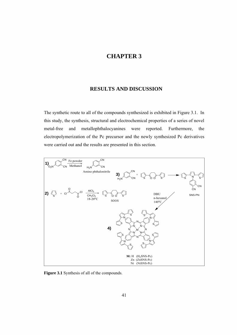
41
CHAPTER 3
3 RESULTS AND DISCUSSION
The synthetic route to all of the compounds synthesized is exhibited in Figure 3.1. In
this study, the synthesis, structural and electrochemical properties of a series of novel
metal-free and metallophthalocyanines were reported. Furthermore, the
electropolymerization of the Pc precursor and the newly synthesized Pc derivatives
were carried out and the results are presented in this section.
CN
CNO2N H2N
CN
CN
Fe powderMethanol
SCl Cl
O
O+
O SS O
AlCl3CH2Cl218-20oC
H2N
CN
CN O SS O S SN
CNCN
DBUn-hexanol140oC
+
SOOS
SNS-PN
Amino phthalonitrile
NN
N
NN
N
N
N
N
S
S
NS
S
N
S
S
NS
S
M
M: H (H2SNS-Pc) Zn (ZnSNS-Pc) Ni (NiSNS-Pc)
1)
3)
2)
4)
Figure 3.1 Synthesis of all of the compounds.

42
Substituted phthalocyanines are prepared by cyclotetramerization of substituted
phthalonitriles. 2(3),9(10),16(17),23(24) (4-tetrasubstituted) Pcs can be synthesized
from 4-substituted phthalonitriles (as in the case of the study) while
1(4),8(11),15(18),22(25) (3-tetrasubstituted) Pcs are obtained from 3-substituted
analogues [9]. In both cases, a mixture of four possible structural isomers is obtained
and they are differentiated by their molecular symmetry: C4h, C2v, Cs and D2h [82].
The 4-tetrasubstituted compounds always occur in the expected statistical mixture of
the isomers as 12.5% C4h, 25% C2v, 50% Cs and 12.5% D2h. However, for the 3-
tetrasubstituted Pcs depending on the central metal ion and the structure of the
peripheral substituent, the composition of the isomers varies [82].
It is also expected in this study that synthesized 4-tetrasubstituted Pc compounds
were prepared as a statistical mixture of four regioisomers. Attempts to separate these
isomers with column chromatography method using different solvents were not
successful.
3.1 Spectroscopic Characterizations
3.1.1 SNS-PN and P(SNS-PN)
3.1.1.1 1H and 13C NMR Spectroscopies
Spectra obtained from 1H NMR and 13C NMR experiments are very useful to confirm
the structural characteristics of the desired SNS-PN (Figure 3.2Figure 3.3)

43
Figure 3.2 1H NMR spectrum of SNS-PN.
Figure 3.3 13C NMR spectrum of SNS-PN.

44
3.1.1.2 Infrared Spectrometry
It is well known that FTIR spectrum of unsubstituted SNS exhibits three strong bands
centered at 692, 778 and 841 cm-1 due to the C-H out of plane bendings of α-
hydrogens of thiophene rings, β-hydrogens of pyrrole ring and β/β’-hydrogens of
thiophene rings, respectively [83].
The FTIR spectra of SNS-PN and its polymer P(SNS-PN) are presented in Figure 3.4.
SNS-PN also exhibits these three strong peaks at 702 cm-1, 770 cm-1and 836 cm-1 due
to the C-H bendings of α/β hydrogens of the five-membered aromatic rings.
Furthermore, the peaks in the region of 1600-1420 cm-1 are assigned skeletal
vibrations of benzene ring and the peak at 2240 cm-1 is due to the cyanide group.
A close inspection of Figure 3.4 reveals that all these peaks are also present in the
FTIR spectrum of P(SNS-PN) except for the peak at 702 cm-1. This peak is due to α-
hydrogens of external thiophene rings and its disappearance confirms the formation
of linear polymer chains via α-α’ linkages.
The broad band observed at around 1650 cm-1 proves the presence of polyconjugation
[84] and the peaks at 1072 cm-1 and 627 cm-1 in the polymer spectrum are due to the
presence of ClO4- dopant [85].
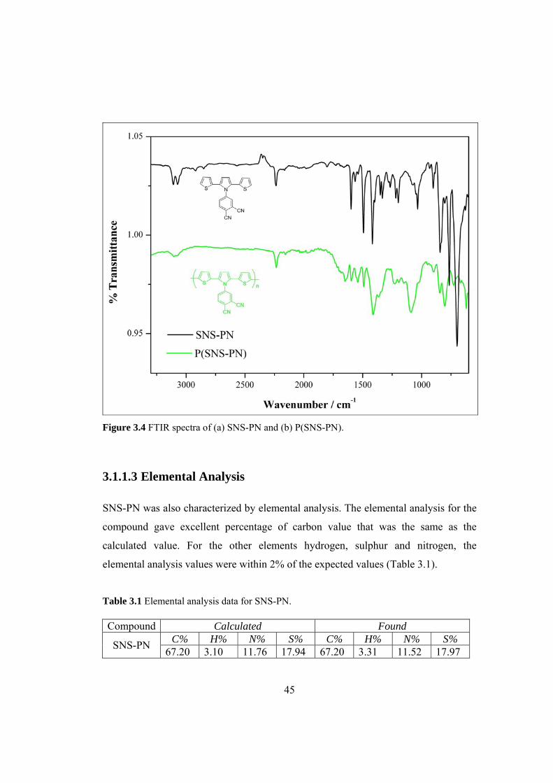
45
Figure 3.4 FTIR spectra of (a) SNS-PN and (b) P(SNS-PN).
3.1.1.3 Elemental Analysis
SNS-PN was also characterized by elemental analysis. The elemental analysis for the
compound gave excellent percentage of carbon value that was the same as the
calculated value. For the other elements hydrogen, sulphur and nitrogen, the
elemental analysis values were within 2% of the expected values (Table 3.1).
Table 3.1 Elemental analysis data for SNS-PN. Compound Calculated Found
C% H% N% S% C% H% N% S% SNS-PN 67.20 3.10 11.76 17.94 67.20 3.31 11.52 17.97

46
3.1.2 H2Pc-SNS, ZnPc-SNS and NiPc-SNS
3.1.2.1 1H and 13C -NMR Spectroscopies
NMR Spectra obtained for Pc complexes were unresolvable in the aromatic region
due to their poor solubility, high aggregation tendency, which results in a low signal
to noise ratio of the spectra, and the compounds being isomerically impure. Thus,
formation of the compounds was supported by FTIR Spectroscopy and elemental
analyses.
3.1.2.2 Elemental Analysis
Elemental analysis was performed in order to verify the composition and purity of Pc
complexes. Percent composition of carbon, hydrogen, nitrogen and sulphur were
determined and are reported in Table 3.2.
Table 3.2 Elemental analysis data for Pc complexes.
Calculated Found
Compound Formula
Mol
Wt
(g/mol)
C
(%)
H
(%)
N
(%)
S
(%)
C
(%)
H
(%)
N
(%)
S
(%)
H2Pc-SNS C80H46N12S8 1431.8 67.11 3.24 11.74 17.92 66.42 3.84 11.74 18.00
ZnPc-SNS C80H44N12S8Zn 1495.2 64.26 2.97 11.24 17.16 64.65 3.09 11.17 17.56
NiPc-SNS C80H44N12S8Ni 1488.5 64.55 2.98 11.29 17.23 64.41 3.11 11.49 16.95

47
Generally, a compound is considered to be pure if the determined composition of
each element remains within a 0.5 % deviation of the calculated value.
The elemental analyses for compounds H2Pc-SNS, ZnPc-SNS and NiPc-SNS gave
percentage carbon results with a deviation smaller than 1.5 %. For compounds ZnPc-
SNS and NiPc-SNS nitrogen and sulphur values were within 2 % of the expected
values. The small differences between calculated and determined compositions can be
greatly assumed to be due to the large number of carbon and hydrogen atoms present
in the molecule. It has been reported before that for large Pc molecules, elemental
analyses often gives unsatisfactory results [86].
Elemental compositions can be affected in several ways. The compound can contain
impurities, unreacted starting material or undesired by-products. It is also common
for compositional determinations to be skewed due to solvent molecules being
trapped within structure of the compound.
3.1.2.3 UV-Vis Absorption Spectroscopy
UV-Vis spectroscopy is a very suitable technique to monitor the presence of
phthalocyanine groups, their substituents and interactions between them.
UV-Vis spectra of the phthalocyanine complexes exhibit characteristic Q- and B-
bands. The Q band in the visible region at 600-750 nm is attributed to the π-π*
transition from HOMO to LUMO of the phthalocyanine ring, and the B-band in the
UV region at 300-400 nm arises from the deeper π-π* transitions [87].

48
The electronic spectra of the complexes in DCM at room temperature are shown in
Figure 3.5. It exhibited a typical Q band at 700 and 665 nm for H2Pc-SNS, 680 nm
for ZnPc-SNS and 670 nm for NiPc-SNS. Compared with H2Pc, the λmax of the MPcs
moved to shorter wavelengths and decreased in the order of ZnPc-SNS, NiPc-SNS,
due to the nature of the central metal ion [88].
Figure 3.5 UV-vis spectra of 1.0 x 10⁻⁴ mol.L-1 for H2Pc-SNS, ZnPc-SNS and NiPc-SNS in DCM. The metal-free phthalocyanine complex H2Pc-SNS gave a doublet (narrow) Q band
as a result of the non-degenerate symmetry of metal-free phthalocyanine which is the
D2h symmetry [89]. All synthesized complexes exhibited B or Soret band between
300 – 350 nm which results from the transition of the deeper π orbitals (b2u and a2u) to
the π* orbitals (eg). These bands overlapped with the absorption band of the SNS unit
[90]. The small absorption bands that appear around 630 nm might be due to the

49
aggregation. Aggregation in Pc complexes is typified by a broadened or split Q band,
with the high energy band being due to the aggregate and the low energy band due to
the monomer [91]. It is usually depicted as a coplanar association of rings progressing
from monomer to dimer and higher order complexes. It is dependent on the
concentration, nature of the solvent, nature of the substituents, complexed metal ions
and temperature [92]. In the aggregated state the electronic structure of the
complexed phthalocyanine rings is perturbed resulting in alternation of the ground
and excited state electronic structures [93].
3.1.2.4 Infrared Spectrometry
It has widely been accepted that vibrational spectroscopy is a versatile technique for
studying the intrinsic properties of Pcs. The FTIR spectra of MPc complexes are
generally complex but similar. The main bands are the C-H stretching vibration at
around 3030 cm-1, C-C ring skeletal stretching vibrations at around 1600 and 1475
cm-1 , C-H out of plane bending vibrations at around 750-790 cm-1 [94], all these
bands are from the aromatic ring of the MPc. The unmetallated Pcs can be
distinguished from the metallated ones by the presence of N-H stretching vibration at
about 3298 cm-1 in the former but absence of the band in the latter [95].
In the case of our monomers, the characteristic nitrile (C≡N) stretching at 2240 cm-1
of SNS-PN disappeared after conversion, indicative of phthalocyanine formation
Figures 3.6, 3.7 and 3.8)

50
Figure 3.6 FTIR spectra of SNS-PN and H2Pc-SNS.
Figure 3.7 FTIR spectra of SNS-PN and ZnPc-SNS.
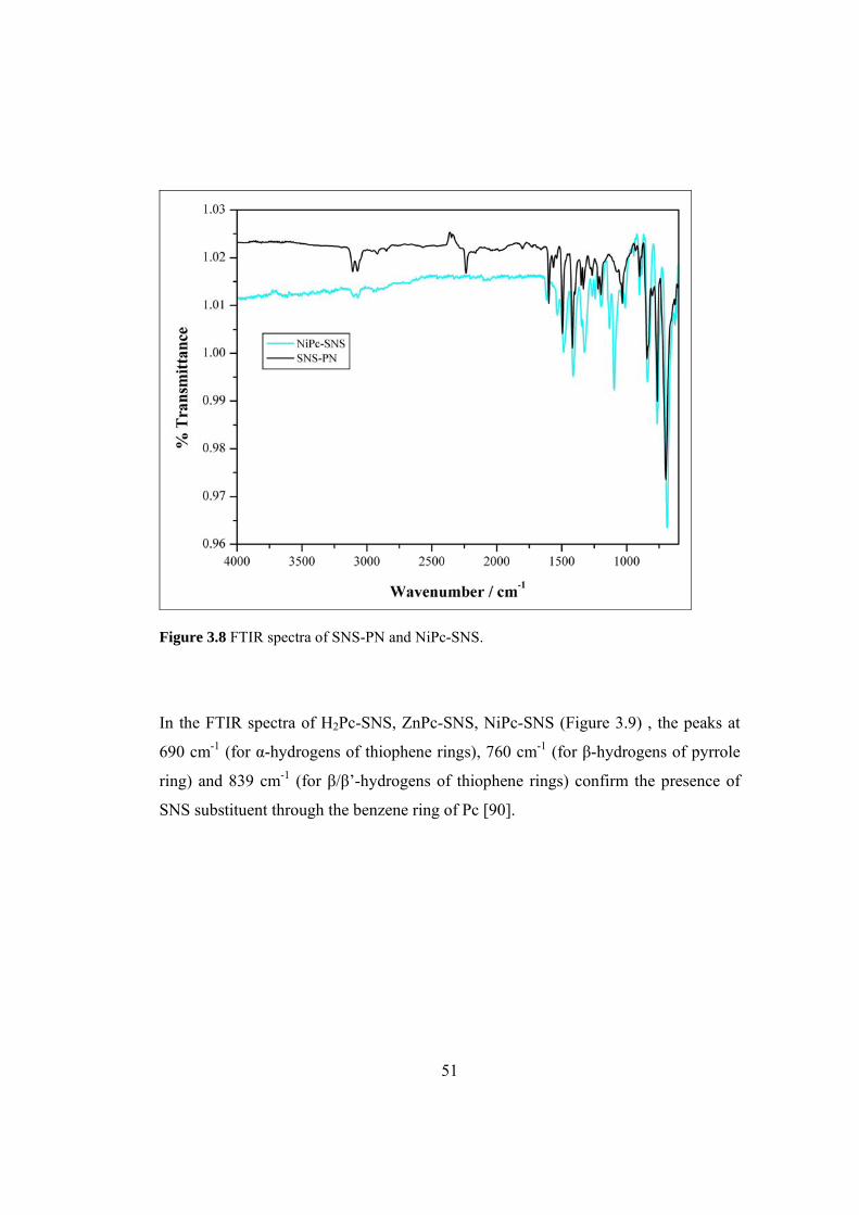
51
Figure 3.8 FTIR spectra of SNS-PN and NiPc-SNS.
In the FTIR spectra of H2Pc-SNS, ZnPc-SNS, NiPc-SNS (Figure 3.9) , the peaks at
690 cm-1 (for α-hydrogens of thiophene rings), 760 cm-1 (for β-hydrogens of pyrrole
ring) and 839 cm-1 (for β/β’-hydrogens of thiophene rings) confirm the presence of
SNS substituent through the benzene ring of Pc [90].
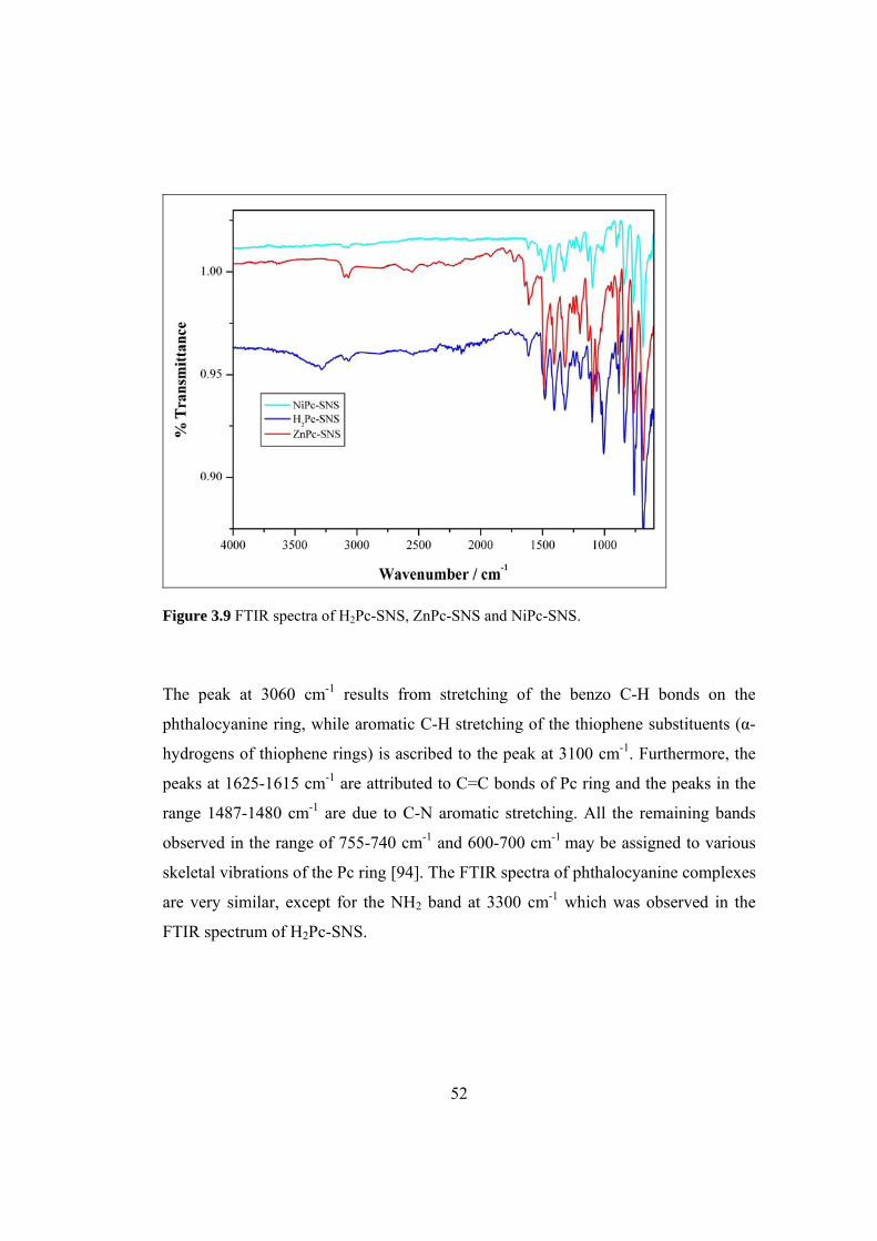
52
Figure 3.9 FTIR spectra of H2Pc-SNS, ZnPc-SNS and NiPc-SNS.
The peak at 3060 cm-1 results from stretching of the benzo C-H bonds on the
phthalocyanine ring, while aromatic C-H stretching of the thiophene substituents (α-
hydrogens of thiophene rings) is ascribed to the peak at 3100 cm-1. Furthermore, the
peaks at 1625-1615 cm-1 are attributed to C=C bonds of Pc ring and the peaks in the
range 1487-1480 cm-1 are due to C-N aromatic stretching. All the remaining bands
observed in the range of 755-740 cm-1 and 600-700 cm-1 may be assigned to various
skeletal vibrations of the Pc ring [94]. The FTIR spectra of phthalocyanine complexes
are very similar, except for the NH2 band at 3300 cm-1 which was observed in the
FTIR spectrum of H2Pc-SNS.
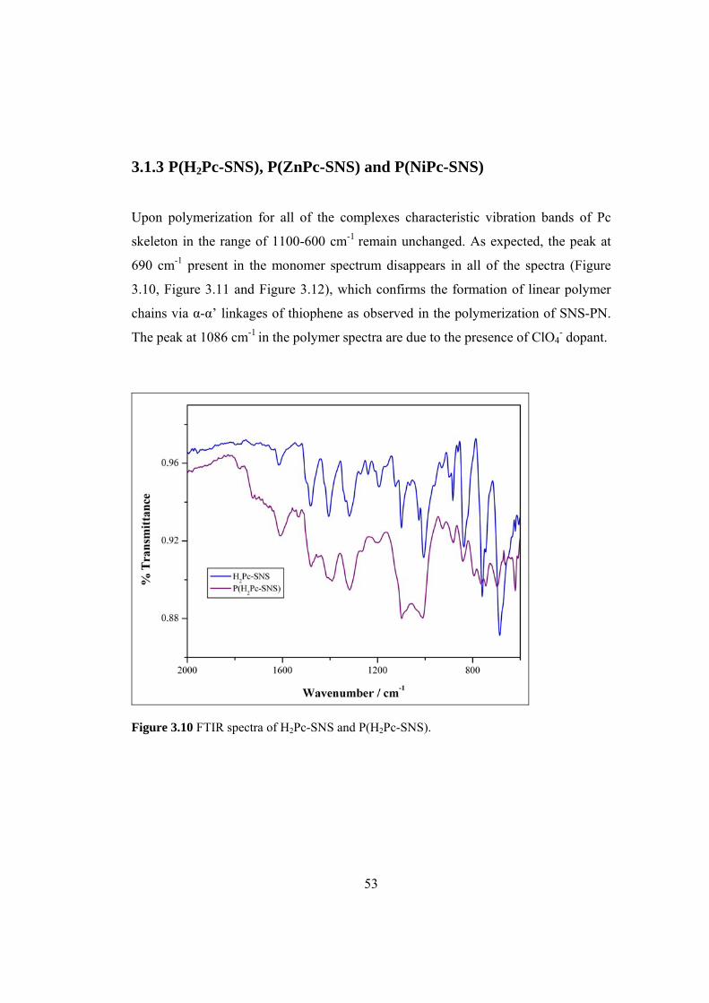
53
3.1.3 P(H2Pc-SNS), P(ZnPc-SNS) and P(NiPc-SNS)
Upon polymerization for all of the complexes characteristic vibration bands of Pc
skeleton in the range of 1100-600 cm-1 remain unchanged. As expected, the peak at
690 cm-1 present in the monomer spectrum disappears in all of the spectra (Figure
3.10, Figure 3.11 and Figure 3.12), which confirms the formation of linear polymer
chains via α-α’ linkages of thiophene as observed in the polymerization of SNS-PN.
The peak at 1086 cm-1 in the polymer spectra are due to the presence of ClO4- dopant.
Figure 3.10 FTIR spectra of H2Pc-SNS and P(H2Pc-SNS).
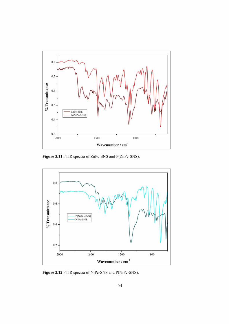
54
Figure 3.11 FTIR spectra of ZnPc-SNS and P(ZnPc-SNS).
Figure 3.12 FTIR spectra of NiPc-SNS and P(NiPc-SNS).
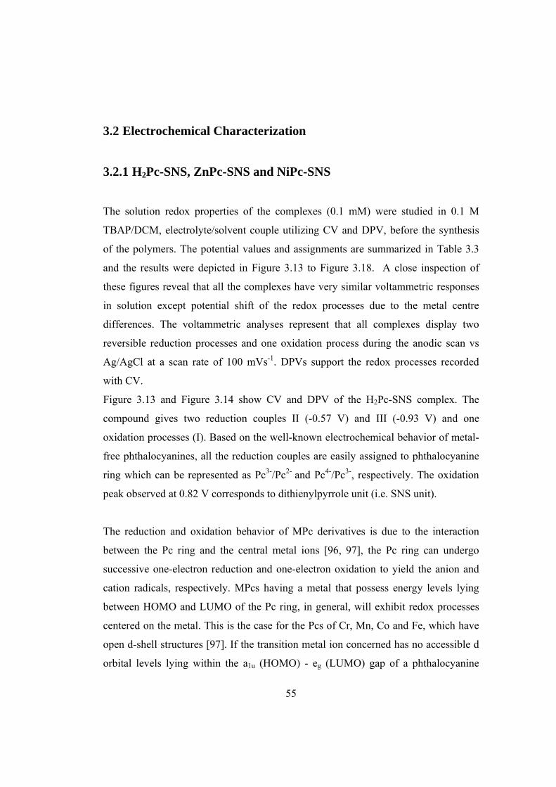
55
3.2 Electrochemical Characterization
3.2.1 H2Pc-SNS, ZnPc-SNS and NiPc-SNS
The solution redox properties of the complexes (0.1 mM) were studied in 0.1 M
TBAP/DCM, electrolyte/solvent couple utilizing CV and DPV, before the synthesis
of the polymers. The potential values and assignments are summarized in Table 3.3
and the results were depicted in Figure 3.13 to Figure 3.18. A close inspection of
these figures reveal that all the complexes have very similar voltammetric responses
in solution except potential shift of the redox processes due to the metal centre
differences. The voltammetric analyses represent that all complexes display two
reversible reduction processes and one oxidation process during the anodic scan vs
Ag/AgCl at a scan rate of 100 mVs-1. DPVs support the redox processes recorded
with CV.
Figure 3.13 and Figure 3.14 show CV and DPV of the H2Pc-SNS complex. The
compound gives two reduction couples II (-0.57 V) and III (-0.93 V) and one
oxidation processes (I). Based on the well-known electrochemical behavior of metal-
free phthalocyanines, all the reduction couples are easily assigned to phthalocyanine
ring which can be represented as Pc3-/Pc2- and Pc4-/Pc3-, respectively. The oxidation
peak observed at 0.82 V corresponds to dithienylpyrrole unit (i.e. SNS unit).
The reduction and oxidation behavior of MPc derivatives is due to the interaction
between the Pc ring and the central metal ions [96, 97], the Pc ring can undergo
successive one-electron reduction and one-electron oxidation to yield the anion and
cation radicals, respectively. MPcs having a metal that possess energy levels lying
between HOMO and LUMO of the Pc ring, in general, will exhibit redox processes
centered on the metal. This is the case for the Pcs of Cr, Mn, Co and Fe, which have
open d-shell structures [97]. If the transition metal ion concerned has no accessible d
orbital levels lying within the a1u (HOMO) - eg (LUMO) gap of a phthalocyanine

56
species, then, its redox chemistry will appear very similar to that of redox inactive
MPcs. Zinc and nickel behave in this fashion, with the Zn(II) and Ni(II) central ions
being unchanged as the Pc unit is either oxidized or reduced [9].
In this study, it is clearly pointed out that all of these processes can be ascribed to the
Pc ring electron transfer reactions. ZnPc-SNS and NiPc-SNS complexes have very
similar CV and DPV responses. CV and DPV of the complexes are given in Figure
3.15 to Figure 3.18 to represent the voltammetric response of the MPs having redox
inactive metal centre.
Both metal complexes give two reversible reduction couples upon negative potential
scan, II (-0.84 V) and III (-1.19 V) for ZnPc-SNS, II (-0.58 V) and III (-0.81 V) for
NiPc-SNS. During the positive potential scan as observed for H2Pc-SNS, the
oxidation couple corresponding to dithienylpyrrole unit is seen for both complexes at
0.84 V and 0.88 V, respectively [90].
Since zinc and nickel Pc complexes are known not to show any redox activity, the
peak couples observed for ZnPc-SNS and NiPc-SNS are also associated with the ring
based processes of Pc.
Table 3.3 Summary of redox potentials (E1/2 vs Ag/AgCl) of the Pc complexes in 0.1 M TBAP dissolved in DCM.
Complex (II) Pc3-/Pc2- (III) Pc4-/Pc3- SNS unit
H2Pc-SNS -0.57 -0.93 0.82
ZnPc-SNS -0.84 -1.19 0.84
NiPc-SNS -0.59 -0.82 0.88

57
Figure 3.13 Cyclic voltammogram of H2Pc-SNS on a Pt disc electrode at 100 mVs-1 in 0.1 M TBAP/DCM
Figure 3.14 DPV of H2Pc-SNS in 0.1 M TBAP/DCM.

58
Figure 3.15 Cyclic voltammogram of ZnPc-SNS on a Pt disc electrode at 100 mVs-1 in 0.1 M TBAP/DCM.
Figure 3.16 DPV of ZnPc-SNS in 0.1 M TBAP / DCM.

59
Figure 3.17 Cyclic voltammogram of NiPc-SNS on a Pt disc electrode at 100 mVs-1 in 0.1 M TBAP/DCM.
Figure 3.18 DPV of NiPc-SNS in 0.1 M TBAP/DCM.

60
3.3 Electropolymerization
3.3.1 SNS-PN
Electrochemical behavior of SNS-PN was investigated in 0.2 M LiClO4/acetonitrile,
electrolyte/solvent couple utilizing CV, before the synthesis of the polymers. Cyclic
voltammogram of electrolytic solution containing 2.0 mM SNS-PN exhibits one
irreversible oxidation peak at 0.92 V vs Ag wire in the first anodic scan. A new
reduction peak is also noted during the reverse scan which intensifies upon successive
scans in the potential range of 0.0 to 1.15 V.
Figure 3.19 Repeated scan electrochemical polymerization of 2.0 x 10⁻³ M SNS-PN at a scan rate of 100mV/s.
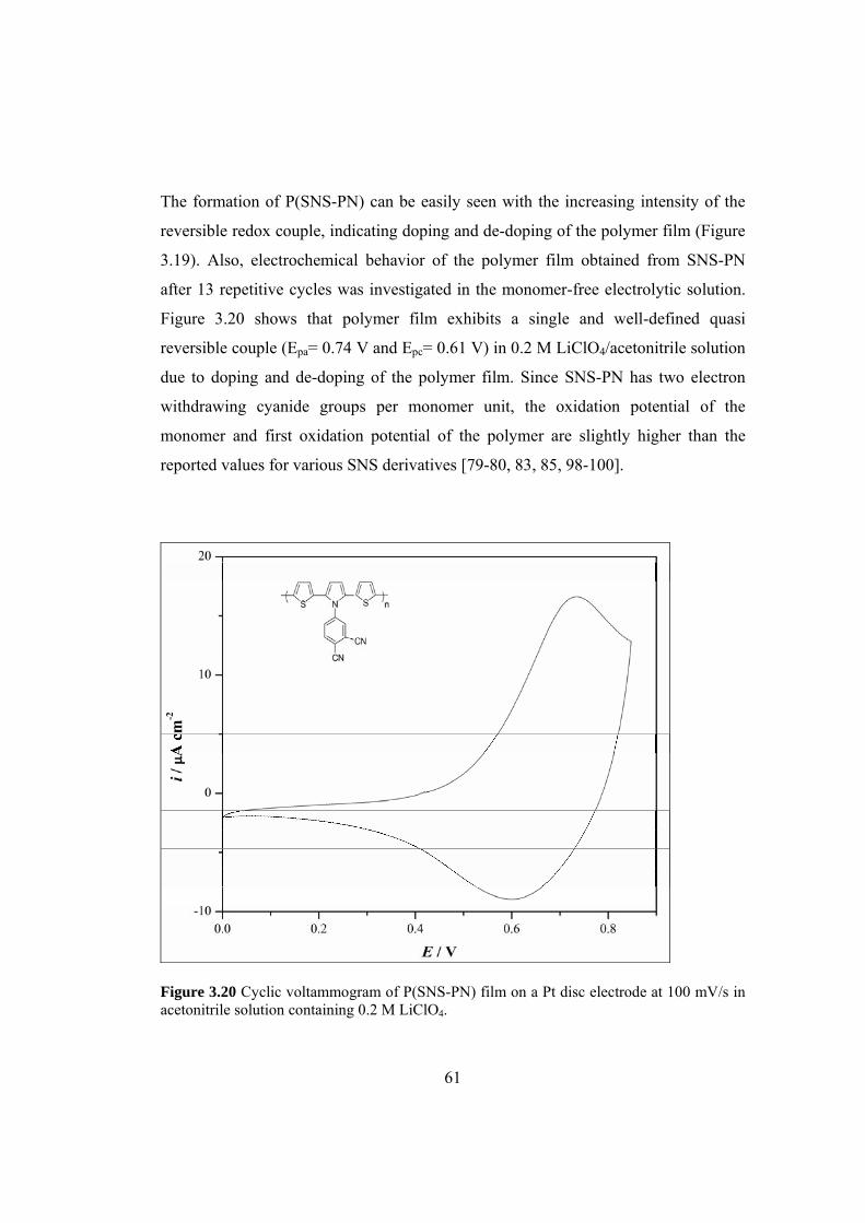
61
The formation of P(SNS-PN) can be easily seen with the increasing intensity of the
reversible redox couple, indicating doping and de-doping of the polymer film (Figure
3.19). Also, electrochemical behavior of the polymer film obtained from SNS-PN
after 13 repetitive cycles was investigated in the monomer-free electrolytic solution.
Figure 3.20 shows that polymer film exhibits a single and well-defined quasi
reversible couple (Epa= 0.74 V and Epc= 0.61 V) in 0.2 M LiClO4/acetonitrile solution
due to doping and de-doping of the polymer film. Since SNS-PN has two electron
withdrawing cyanide groups per monomer unit, the oxidation potential of the
monomer and first oxidation potential of the polymer are slightly higher than the
reported values for various SNS derivatives [79-80, 83, 85, 98-100].
Figure 3.20 Cyclic voltammogram of P(SNS-PN) film on a Pt disc electrode at 100 mV/s in acetonitrile solution containing 0.2 M LiClO4.

62
In order to see if these electron withdrawing cyanide groups can interact with any
metal cation through nitrogen atoms, cyclic voltammograms of the polymer film were
also recorded after keeping the film in contact with a solution containing either TBAP
or sodium perchlorate (NaClO4) for five minutes.
The results are depicted in Figure 3.21. As seen from Figure 3.21, oxidation peak of
the polymer film shifted anodically. This result clearly indicates an interaction
between cyanide groups present on the polymer chains and cations, thus reducing the
electron withdrawing effect of these groups on the polymer film oxidation.
Figure 3.21 Cyclic voltammogram of P(SNS-PN) film (25 mC/cm2) on a Pt disc electrode in acetonitrile containing 0.2 M LiClO4, NaClO4, and TBAP.
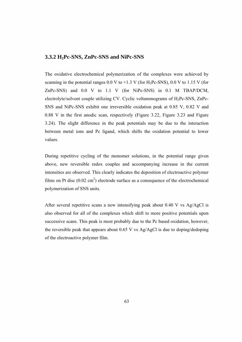
63
3.3.2 H2Pc-SNS, ZnPc-SNS and NiPc-SNS
The oxidative electrochemical polymerization of the complexes were achieved by
scanning in the potential ranges 0.0 V to +1.3 V (for H2Pc-SNS), 0.0 V to 1.15 V (for
ZnPc-SNS) and 0.0 V to 1.1 V (for NiPc-SNS) in 0.1 M TBAP/DCM,
electrolyte/solvent couple utilizing CV. Cyclic voltammograms of H2Pc-SNS, ZnPc-
SNS and NiPc-SNS exhibit one irreversible oxidation peak at 0.85 V, 0.82 V and
0.88 V in the first anodic scan, respectively (Figure 3.22, Figure 3.23 and Figure
3.24). The slight difference in the peak potentials may be due to the interaction
between metal ions and Pc ligand, which shifts the oxidation potential to lower
values.
During repetitive cycling of the monomer solutions, in the potential range given
above, new reversible redox couples and accompanying increase in the current
intensities are observed. This clearly indicates the deposition of electroactive polymer
films on Pt disc (0.02 cm2) electrode surface as a consequence of the electrochemical
polymerization of SNS units.
After several repetitive scans a new intensifying peak about 0.40 V vs Ag/AgCl is
also observed for all of the complexes which shift to more positive potentials upon
successive scans. This peak is most probably due to the Pc based oxidation, however,
the reversible peak that appears about 0.65 V vs Ag/AgCl is due to doping/dedoping
of the electroactive polymer film.

64
Figure 3.22 Repeated potential scan electropolymerization of 0.1 mM H2Pc-SNS on a Pt disc electrode at 100 mVs-1 in 0.1 M TBAP/DCM.
Figure 3.23 Repeated potential scan electropolymerization of 0.1 mM ZnPc-SNS on a Pt disc electrode at 100 mVs-1 in 0.1 M TBAP/DCM.
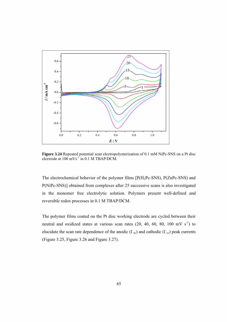
65
Figure 3.24 Repeated potential scan electropolymerization of 0.1 mM NiPc-SNS on a Pt disc electrode at 100 mVs-1 in 0.1 M TBAP/DCM.
The electrochemical behavior of the polymer films [P(H2Pc-SNS), P(ZnPc-SNS) and
P(NiPc-SNS)] obtained from complexes after 25 successive scans is also investigated
in the monomer free electrolytic solution. Polymers present well-defined and
reversible redox processes in 0.1 M TBAP/DCM.
The polymer films coated on the Pt disc working electrode are cycled between their
neutral and oxidized states at various scan rates (20, 40, 60, 80, 100 mV s-1) to
elucidate the scan rate dependence of the anodic (I ac) and cathodic (I cc) peak currents
(Figure 3.25, Figure 3.26 and Figure 3.27).
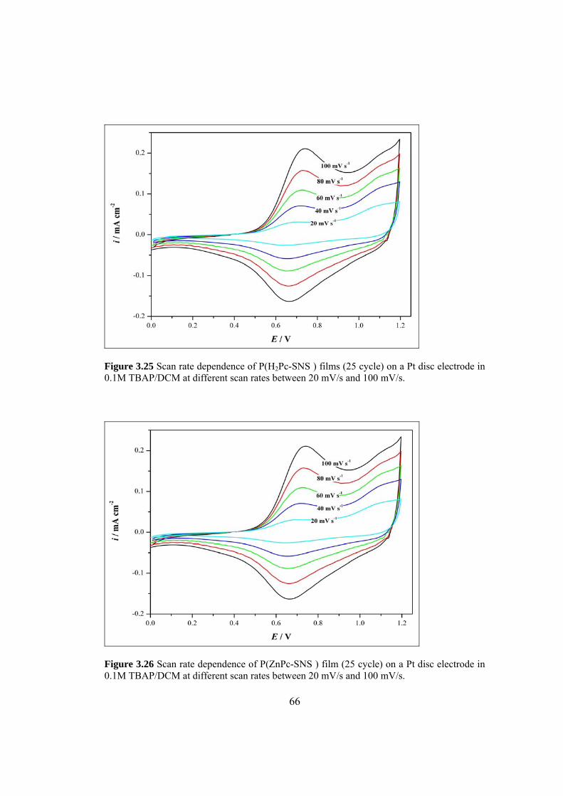
66
Figure 3.25 Scan rate dependence of P(H2Pc-SNS ) films (25 cycle) on a Pt disc electrode in 0.1M TBAP/DCM at different scan rates between 20 mV/s and 100 mV/s.
Figure 3.26 Scan rate dependence of P(ZnPc-SNS ) film (25 cycle) on a Pt disc electrode in 0.1M TBAP/DCM at different scan rates between 20 mV/s and 100 mV/s.

67
Figure 3.27 Scan rate dependence of P(NiPc-SNS ) film (25 cycle) on a Pt disc electrode in 0.1M TBAP/DCM at different scan rates between 20 mV/s and 100 mV/s.
The Randles-Sevcik equation states that the peak current is given by ip = (2.69×10⁵) n3/2 A D1/2 Cb ν1/2 (1) where n is the number of electrons in the reaction, A is the surface area of the
electrode (cm2), D is the diffusion coefficient (cm2s-1), Cb is the bulk concentration of
the electroactive species (mol cm-3), ν is the scan rate (V s-1). From this equation it
can be concluded that for a diffusion-controlled system, the peak current is
proportional to the square root of the scan rate in a reversible system. For these
processes, it was assumed that the reactants and products are soluble in solution and
the surface processes (adsorption of reactants and products) can be neglected.
However, the rules change in electroactive polymer electrochemistry, because the
polymer is adhered to electrode surface. Therefore, the process is not diffusion-
controlled, and cannot be described by the Randles-Sevcik equation discussed above.
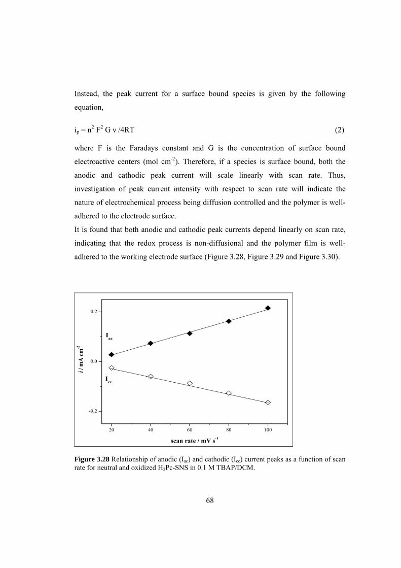
68
Instead, the peak current for a surface bound species is given by the following
equation,
ip = n2 F2 G ν /4RT (2) where F is the Faradays constant and G is the concentration of surface bound
electroactive centers (mol cm-2). Therefore, if a species is surface bound, both the
anodic and cathodic peak current will scale linearly with scan rate. Thus,
investigation of peak current intensity with respect to scan rate will indicate the
nature of electrochemical process being diffusion controlled and the polymer is well-
adhered to the electrode surface.
It is found that both anodic and cathodic peak currents depend linearly on scan rate,
indicating that the redox process is non-diffusional and the polymer film is well-
adhered to the working electrode surface (Figure 3.28, Figure 3.29 and Figure 3.30).
Figure 3.28 Relationship of anodic (Iac) and cathodic (Icc) current peaks as a function of scan rate for neutral and oxidized H2Pc-SNS in 0.1 M TBAP/DCM.

69
Figure 3.29 Relationship of anodic (Iac) and cathodic (Icc) current peaks as a function of scan rate for neutral and oxidized ZnPc-SNS in 0.1 M TBAP/DCM.
Figure 3.30 Relationship of anodic (Iac) and cathodic (Icc) current peaks as a function of scan rate for neutral and oxidized NiPc-SNS in 0.1 M TBAP/DCM.

70
In order to see if the cavity of the metal free phthalocyanine ring can interact with any
metal cation, cyclic voltammograms of P(H2Pc-SNS) are also recorded after keeping
the film in contact with a solution containing TBAP and zinc (II) acetate solutions for
ten minutes.
The results are depicted in Figure 3.31. As seen from Figure 3.31, oxidation peak of
the polymer film shifted anodically after being kept in contact with zinc (II) acetate
solution. A comparison of this voltammogram with that of recorded for P(ZnPc-
SNS) (Figure 3.26) clearly indicates an interaction between zinc (II) ion and Pc ring.
Figure 3.31 Cyclic voltammogram of P(H2Pc-SNS) film (10 cycle) on a Pt disc electrode in DCM containing 0.1 M zinc (II) acetate and TBAP .

71
3.4 Spectroelectrochemistry
3.4.1 P(SNS-PN)
The important modifications of the absorption spectra of the polymers are reflected in
the electronic transitions between their doped and neutral states of polymers result in.
On the basis of these electro-optical properties, the use of the films as active element
in smart windows and electrochromic display devices is possible.
For this purpose, P(SNS-PN) film was deposited on ITO and its electrochemical
behavior was studied in the monomer-free electrolytic solution containing 0.2 M
LiClO4 and acetonitrile. After polymerization, the films were rinsed with acetonitrile
to remove any unreacted monomer. Prior to spectroelectrochemical investigation, the
polymer film on ITO was switched between neutral and doped states several times in
order to equilibrate its redox behavior in monomer-free electrolytic solution. The
changes in electronic absorption spectra recorded in-situ at various applied potentials
are depicted in Figure 3.32.

72
Figure 3.32 In-situ absorption spectra of P(SNS-PN) (55 mC/cm2) recorded in acetonitrile containing 0.2 M LiClO4 at various applied potentials.
As seen from Figure 3.32, the electronic absorption spectrum of the neutral form of
the polymer film exhibits a band at about 389 nm due to π-π* transition and from its
commencement on the low energy end the band gap (Eg) was found to be 2.45 eV
[79, 84, 98, 99]. This value is slightly lower than the band gap of PSNS (2.6 eV) [83]
and this difference may be attributed to the presence of electron withdrawing cyanide
groups which induce a decrease in both HOMO and LUMO levels. [103]. Beyond
0.6 V, two new bands at 618 nm (~2.01 eV) and at 864 nm (~1.44 eV) start to
intensify indicating the formation of polarons [104], and bipolarons, respectively. It is
also noteworthy that P(SNS-PN) film can be reversibly switched between its neutral

73
and oxidized states and exhibits electrochromic behavior; yellow in the neutral and
blue in the oxidized state.
3.4.2 P(H2Pc-SNS), P(ZnPc-SNS) and P(NiPc-SNS)
For spectroelectrochemical investigations, the polymer films were electrodeposited
on ITO electrode via constant potential electrolysis at 1.1 V (25 mC/cm2). When 25
mC/cm2 achieved the electropolymerization was stopped, the electrodes were then
rinsed with DCM to remove the traces of unreacted monomers or oligomeric species
and then transferred into monomer-free electrolytic solution.
The changes in the electronic absorption spectrum were recorded during potential
scanning from -0.2 V to 1.2 V with a voltage scan rate of 100 mV/s and the results
are depicted in Figure 3.33, Figure 3.34 and Figure 3.35.
An inspection of Figure 3.33 reveals that P(H2Pc-SNS) film, in its neutral state,
exhibits three absorption bands at 345 nm, 675 nm and 705 nm which makes the
polymer appear in green color. The Eg of the P(H2Pc-SNS) was found as 2.38 eV by
the commencement on the low energy end of the π-π* transitions at 345 nm. Upon
increasing the potential, the color of the P(H2Pc-SNS) film turns to turquoise green,
which is accompanied with the corresponding changes in the absorption bands.
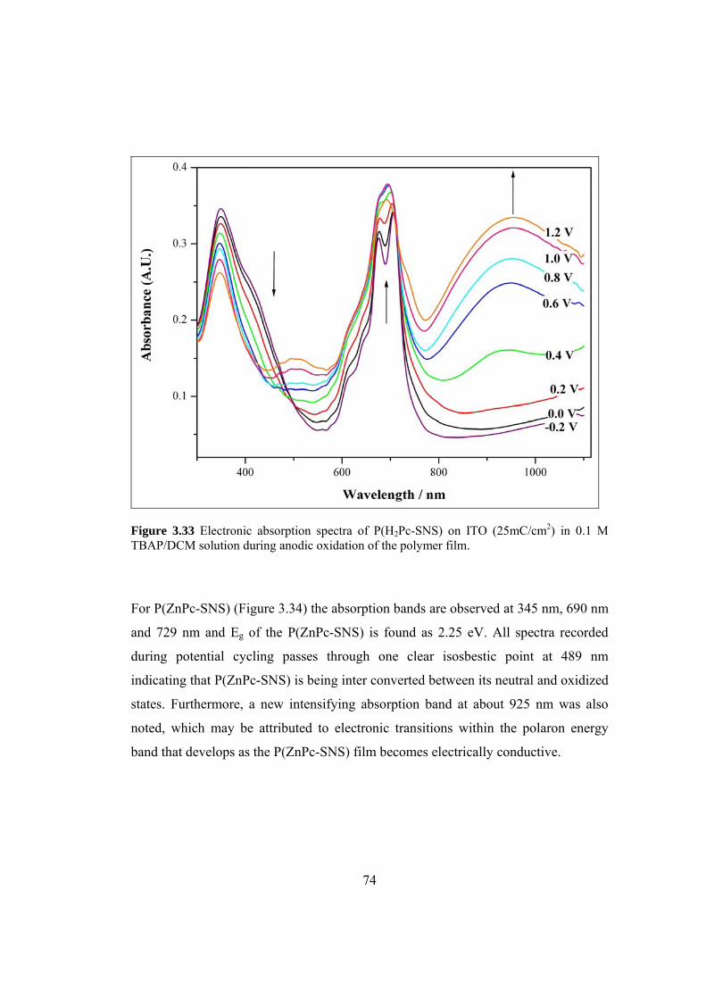
74
Figure 3.33 Electronic absorption spectra of P(H2Pc-SNS) on ITO (25mC/cm2) in 0.1 M TBAP/DCM solution during anodic oxidation of the polymer film.
For P(ZnPc-SNS) (Figure 3.34) the absorption bands are observed at 345 nm, 690 nm
and 729 nm and Eg of the P(ZnPc-SNS) is found as 2.25 eV. All spectra recorded
during potential cycling passes through one clear isosbestic point at 489 nm
indicating that P(ZnPc-SNS) is being inter converted between its neutral and oxidized
states. Furthermore, a new intensifying absorption band at about 925 nm was also
noted, which may be attributed to electronic transitions within the polaron energy
band that develops as the P(ZnPc-SNS) film becomes electrically conductive.

75
Figure 3.34 Electronic absorption spectra of P(ZnPc-SNS) on ITO (25mC/cm2) in 0.1 M TBAP/DCM solution during anodic oxidation of the polymer film.
Figure 3.35 shows the electronic absorption spectra of P(NiPc-SNS) with the bands at
340 nm, 616 nm and 680 nm. By the commencement on the low energy end of the π-
π* transitions at 340 nm, Eg of the P(NiPc-SNS) is found as 2.69 eV. Upon increasing
the potential, the green color of the P(NiPc-SNS) film turns to blue.
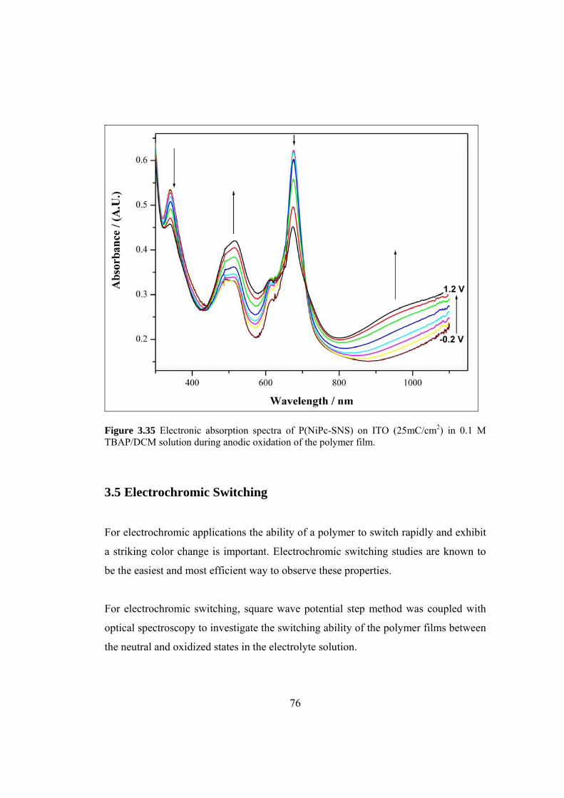
76
Figure 3.35 Electronic absorption spectra of P(NiPc-SNS) on ITO (25mC/cm2) in 0.1 M TBAP/DCM solution during anodic oxidation of the polymer film.
3.5 Electrochromic Switching
For electrochromic applications the ability of a polymer to switch rapidly and exhibit
a striking color change is important. Electrochromic switching studies are known to
be the easiest and most efficient way to observe these properties.
For electrochromic switching, square wave potential step method was coupled with
optical spectroscopy to investigate the switching ability of the polymer films between
the neutral and oxidized states in the electrolyte solution.
77
The coloration efficiency (CE) of the polymer films which is a measure of optical
density change (∆OD) as a function of injected/ejected charge (Qd) were also
calculated utilizing the following equations [105, 106].
CE = ∆OD/Qd (3)
where ∆OD is the change in optical density and Qd is the charge (C/cm2) passed
during this process. ∆OD is determined from the percent transmittance (%T) before
and after a full switch and is calculated using eqn (4), where Tcolored and Tbleached are
the transmittance in the oxidized and neutral states, respectively,
∆OD = log (%T of bleached state / %T of colored state) (4)
3.5.1 P(SNS-PN)
It was found that P(SNS-PN) film can be reversibly switched between its neutral and
oxidized states and exhibits electrochromic behavior; yellow in the neutral and blue
in the oxidized state. Switching times and optical contrast in the polymer film on ITO
are determined with a change in transmittance at 389, 618 and 864 nm where the
maximum transmittance difference between redox states was observed in the visible
and near infrared region.
The charge passed at 95 % of the optical switch was used to evaluate CE since
beyond which the naked eye cannot sense the color difference. The polymer film
coated on ITO (55 mC/cm2) was switched between 0.0 V and 1.1 V vs Ag-wire and
the time required to attain 95 % of the total transmittance difference was found to be
1.7 s for fully oxidized state and 1.5 s for fully neutral state at 389 nm. Also, the
value of CE at 864 nm was found as 266 cm2/C (see Table 3.4).

78
Table 3.4 Voltammetric and spectroelectrochemical data for P(SNS-PN) recorded in AN containing 0.1 M LiClO4.
3.5.2 P(H2Pc-SNS), P(ZnPc-SNS) and P(NiPc-SNS)
The switching ability of the polymer films P(H2Pc-SNS), P(ZnPc-SNS) and P(NiPc-
SNS) between neutral and doped states in the electrolytic solution was investigated
and it was observed that the polymer films exhibit electrochromic behavior.
The change in electro-optical responses was recorded in situ while switching between
0.0 V and 1.1 V with a residence time of 10 s. The ∆OD and CE of the polymer films
were calculated using equations (3) and (4) (Sec. 3.5).
Values are reported at 90% of a full switch, beyond which the naked eye cannot sense
the difference. As seen from Table 3.5, Table 3.6 and Table 3.7 the CE of P(NiPc-
SNS) is notably higher than that of P(H2Pc-SNS) and P(ZnPc-SNS). This can be
expressed by different doping levels of phthalocyanine polymers.
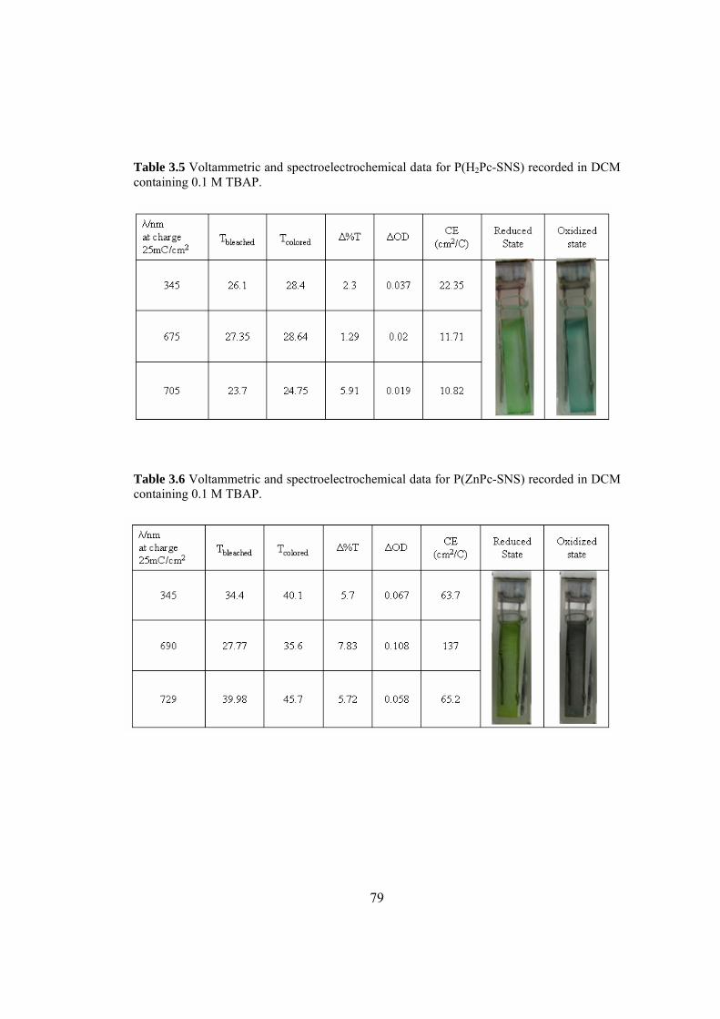
79
Table 3.5 Voltammetric and spectroelectrochemical data for P(H2Pc-SNS) recorded in DCM containing 0.1 M TBAP.
Table 3.6 Voltammetric and spectroelectrochemical data for P(ZnPc-SNS) recorded in DCM containing 0.1 M TBAP.

80
Table 3.7 Voltammetric and spectroelectrochemical data for P(NiPc-SNS) recorded in DCM containing 0.1 M TBAP.
3.6 Fluorescence Study
3.6.1 P(SNS-PN)
Since the electrochemically obtained P(SNS-PN) was found to be soluble in DMF
(0.034 g/100 mL) and partially soluble in DMSO, the fluorescence property of both
monomer and polymer were investigated in these solvents.
Although the monomer exhibits a weak emission at about 400 nm, its polymer has a
relatively intense emission band at the same wavelength when excited at 340 nm,
corresponding to blue color (Figure 3.36). These results indicate that this polymer is
a blue light emitter and it may find applications in various fields, such as organic
lasers and electroluminescent materials.
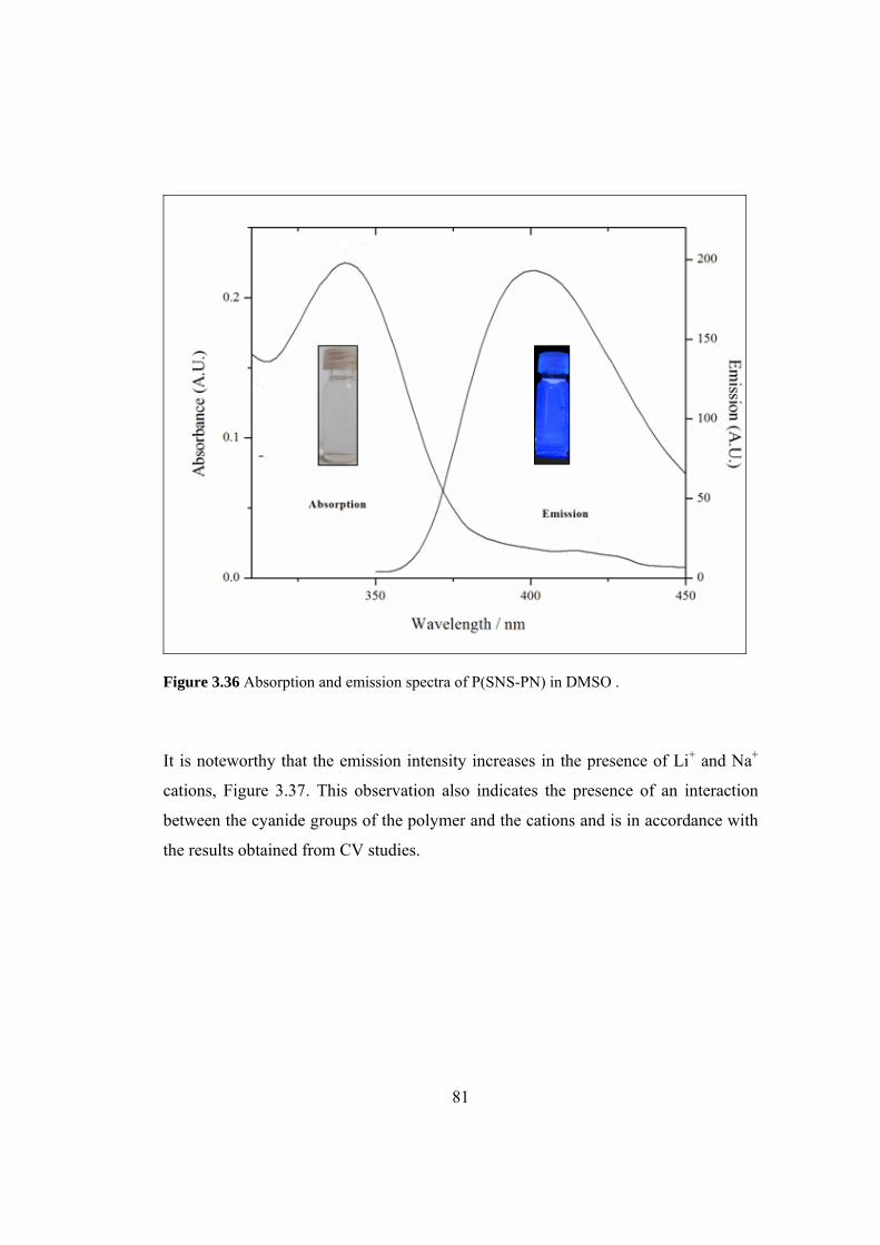
81
Figure 3.36 Absorption and emission spectra of P(SNS-PN) in DMSO .
It is noteworthy that the emission intensity increases in the presence of Li+ and Na+
cations, Figure 3.37. This observation also indicates the presence of an interaction
between the cyanide groups of the polymer and the cations and is in accordance with
the results obtained from CV studies.
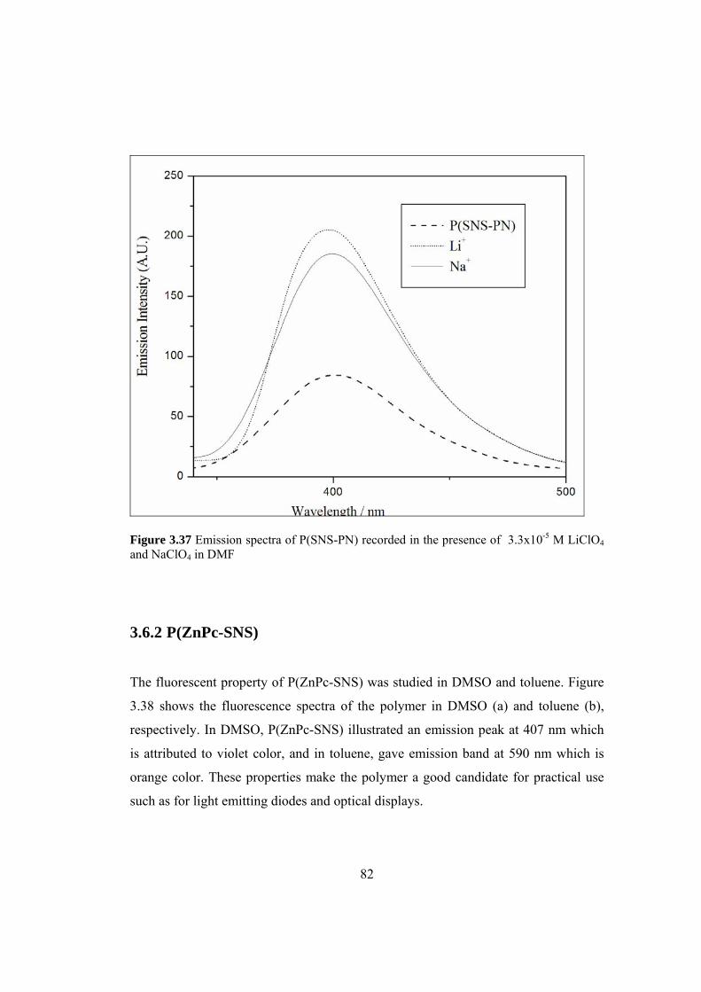
82
Figure 3.37 Emission spectra of P(SNS-PN) recorded in the presence of 3.3x10⁻⁵ M LiClO4 and NaClO4 in DMF
3.6.2 P(ZnPc-SNS)
The fluorescent property of P(ZnPc-SNS) was studied in DMSO and toluene. Figure
3.38 shows the fluorescence spectra of the polymer in DMSO (a) and toluene (b),
respectively. In DMSO, P(ZnPc-SNS) illustrated an emission peak at 407 nm which
is attributed to violet color, and in toluene, gave emission band at 590 nm which is
orange color. These properties make the polymer a good candidate for practical use
such as for light emitting diodes and optical displays.
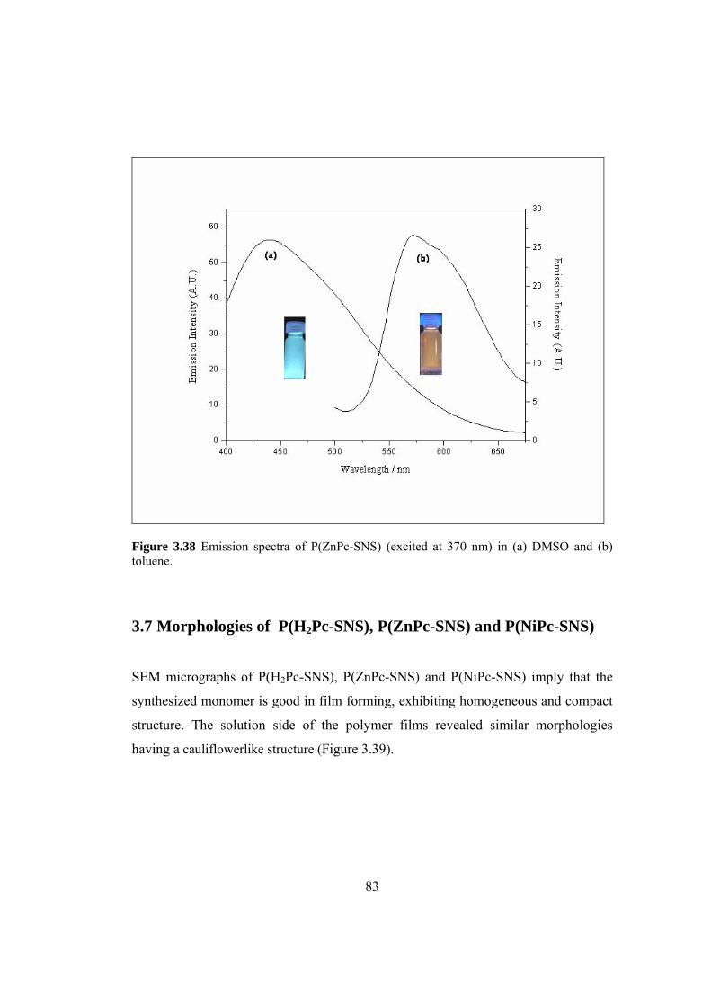
83
Figure 3.38 Emission spectra of P(ZnPc-SNS) (excited at 370 nm) in (a) DMSO and (b) toluene.
3.7 Morphologies of P(H2Pc-SNS), P(ZnPc-SNS) and P(NiPc-SNS)
SEM micrographs of P(H2Pc-SNS), P(ZnPc-SNS) and P(NiPc-SNS) imply that the
synthesized monomer is good in film forming, exhibiting homogeneous and compact
structure. The solution side of the polymer films revealed similar morphologies
having a cauliflowerlike structure (Figure 3.39).
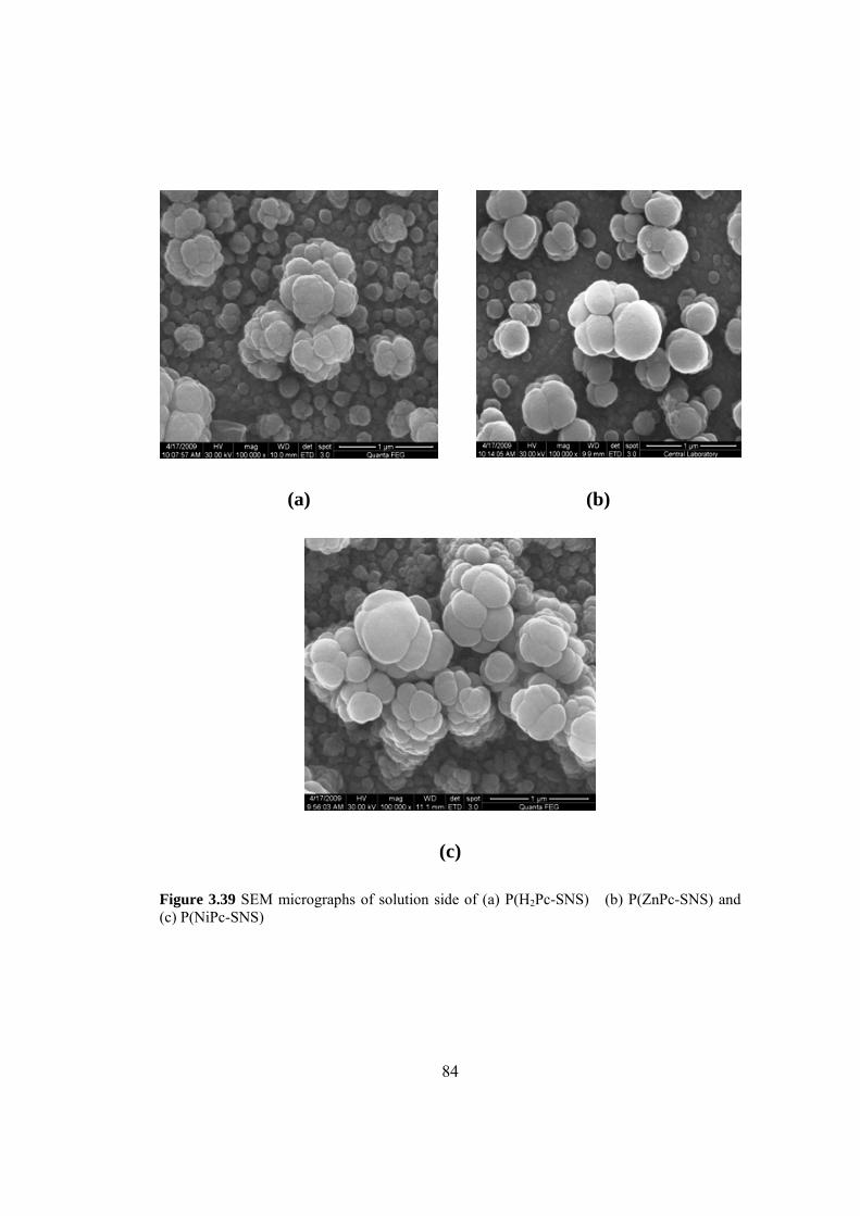
84
(a) (b)
(c)
Figure 3.39 SEM micrographs of solution side of (a) P(H2Pc-SNS) (b) P(ZnPc-SNS) and (c) P(NiPc-SNS)

85
CHAPTER 4
CONCLUSION
In the first part of this study, the synthesis of a new Pc precursor, SNS-PN, was
successfully achieved by utilizing 1,4-di(2-thienyl)-1,4-butadione and 4-
aminophthalonitrile via Knorr-Paal Reaction. Characterization of this compound was
performed by NMR and FTIR spectroscopies and elemental analysis. Its
corresponding polymer was synthesized by electropolymerization in
LiClO4/acetonitrile electrolytic medium and characterized by CV, UV–vis and FTIR
spectroscopic techniques. Since SNS-PN has two electron withdrawing cyanide
groups per monomer unit, the oxidation potential of the monomer and first oxidation
potential of the polymer are slightly higher than the reported values for various SNS
derivatives.
Spectroelectrochemical analyses revealed that the polymer of SNS-PN has electronic
band gap of 2.45 eV. The time required to attain 95% of the total transmittance
difference was found to be 1.7 s for P(SNS-PN). Optical contrast values were
measured as 24 %. The polymer film, besides exhibiting a well-defined and reversible
redox process in acetonitrile, also exhibits stable electrochromic behavior: yellow in
the neutral state and blue in the oxidized state. Soluble part of the polymer in DMSO
has the fluorescent property emitting blue light. Moreover, the fluorescence intensity
enhances in the presence of several cations, in DMF, due to the interactions between
cyanide groups and cations. This result and the shifts in the oxidation potential of the
polymer film makes P(SNS-PN) also a candidate in cation sensing, besides its use in
organic lasers and electroluminescent materials.

86
In the second part, novel tetrakis SNS substituted H2Pc-SNS, ZnPc-SNS and NiPc-
SNS complexes were synthesized and characterized by elemental analysis, FTIR and
UV-Vis spectroscopies. The oxidative electrochemical polymerization of these
complexes were achieved in 0.1 M TBAP/DCM, electrolyte/solvent couple utilizing
CV. Cyclic voltammograms of H2Pc-SNS, ZnPc-SNS and NiPc-SNS exhibited one
irreversible oxidation peak at 0.85 V, 0.82 V and 0.88 V in the first anodic scan,
respectively. The slight difference in the peak potentials may be due to the interaction
between metal ions and Pc ligand, which shifts the oxidation potential to lower
values.
Electrochemical and spectroelectrochemical properties of the polymer films were
investigated via in-situ spectroelectrochemical and CV techniques in monomer free
electrolytic medium. The polymer films were found to exhibit a well-defined and
reversible redox processes accompanied by electrochromic changes which make both
polymers a candidate for electrochromic material applications. Although all of the
polymer films were green in their neutral states, they exhibit different colors in their
oxidized state (P(H2Pc-SNS) turquoise green, P(ZnPc-SNS) black and P(NiPc-SNS)
blue). The Eg of the P(H2Pc-SNS), P(ZnPc-SNS) and P(NiPc-SNS) were found as
2.38 eV, 2.25 eV and 2.69 eV, respectively. The fluorescent property of P(ZnPc-
SNS) was studied in DMSO and toluene. Fluorescence measurement showed that the
P(ZnPc-SNS) is a good blue and orange light emitter which may find applications in
organic lasers and/or LEDs.
87
REFERENCES
[1] A. Braun, J. Tscherniac, Berichte der Deutschen Chemischen Gesellschaft 40
(1907) 2709.
[2] H. Diesbach, E. Weid, Helv. Chim. Acta 10 (1927) 886.
[3] A.G. Dandridge, H.A.E. Drescher, A.R. Thomas, Dyes 322 (1929) 169.
[4] C.T.J. Cronshaw, Endeavour 1 (1942) 79.
[5] (a) R. Linstead, A.Lowe, J. Chem. Soc. (1934) 1016 (b) M. Hesse, H. Meier, B.
Zeeh, Spektroskopische Methoden in der Organischen Chemie. Auflage Goerge
Thieme Verlag Stuttgart, New York (1991) (c) G. Byrne, R. Linstead, A. Lowe,
J. Chem. Soc. (1934) 1017 (d) R. Linstead, A. Lowe, J. Chem. Soc. (1934)
1022 (e) C. Dent, R. Linstead, J. Chem. Soc. (1934) 1027.
[6] (a) J. Robertson, J. Chem. Soc. (1934) 615 (b) J. Robertson, I. Woodward, J.
Chem. Soc. (1937) 219.
[7] (a) P. Turek, P. Petit, J. Andre, J. Simon, R. Even, J. Am. Chem. Soc. 109
(1987) 5119 (b) P. Moskalev, I. Kirin, Russ. J. Phys. Chem. 46 (1972) 1778 (c)
J. Andre, K. Holczer, P. Petit, R. Even, Chem. Phys. Lett. 115 (1985), 115 463.
[8] W.M. Sharman, J.E. van Lier, Synthesis of Phthalocyanine Precursors in The
Porphyrin Handbook, Vol. 15, Academic Press (2003).
[9] C.C. Leznoff, A.B.P. Lever (Eds.) Phthalocyanine: Properties and application
Vol.1-4, VCH, New York, (1989-1996).
[10] N. McKeown The synthesis of symmetrical phthalocyanines in The Porphyrin
Handbook, Vol. 15, Academic Press, (2003).
[11] M. Sommerauer, C. Rager, M. Hanack, J. Am. Chem. Soc. 118 (1996) 10085
[12] N. McKeown, Science of Synthesis, Vol. 17, Capital 9, Thieme Chemistry,
Rochdale, UK, (2005).
[13] I. Rosenthal, E. Ben-Hur, Phthalocyanines Properties and Applications, in
C.C. Leznoff, A.B.P. Lever, VCH, Vol. 1, 393-425 (1989).

88
[14] I. Rosenthal, Photochem. Photobiol. 53 (1991) 859.
[15] B.W. Henderson, T.J. Dougherty, Photochem. Photobiol. 55 (1992) 145.
[16] M.K. Emmelius, G. Pawlowski, H. Vollman, Angew. Chem. 28 (1989) 1445.
[17] M.M Nicolson, in C.C. Leznoff, A.B.P. Lever, Phthalocyanines Properties and
Applications, VCH, New York, Vol. 3, 75-117 (1993).
[18] K.M. Brown, K.T. Gleim, P. Urban, Oil Gas 57 (1959) 73.
[19] P. Salazar, Handbook of Petroleum Process, in R.A. Meyers Part 9, McGraw-
Hill, New York.
[20] G. Schneider, D. Wohrle, W. Spiller, J. Stark, G. Schulz-Ekloff, Photochem.
Photobiol. 60 (1994) 333.
[21] R. Gerdes, O. Bartels, G. Schneider, D. Wohrle, G. Schulz-Ekloff, Int. J.
Photoenergy 1 (1999) 41.
[22] D. Wohrle, O. Suvorova, R. Gerdes, O. Bartels, L. Lapok, N. Baziakina, S.
Makarov, A. Slodek, Processes of Petrochemistry and Oil Refining 3 (2002) 30.
[23] D. Wohrle, D. Meissner, Adv. Mater. 3 (1991) 129.
[24] M.K. Nazeeruddin, M. Humphry-Baker, M. Gratzel, B.A. Murrer, Chem.
Commun. (1998) 719.
[25] M.K. Nazeeruddin, M. Humphry-Baker, M. Gratzel, D.Wohrle, G. Schnurpfeil,
G. Schneider, A. Hirth, N. Trombach, J. Porphyrins Phthalocyanines 3 (1999)
230.
[26] C. Piechocki, J. Simon, A. Skoulious, D. Guillon, P. Weber, J. Am. Chem. Soc.
104 (1982) 5245.
[27] A.N. Cammidge, M.J. Cook, K.J. Harrison, N.B. McKeown, J. Chem.
Soc.,Perkin Trans. 1 (1991) 3053.
[28] J. Batey, M.C. Petty, G.G. Roberts, D.R. Wright, Electron. Lett. 20 (1984) 489.
[29] J.H. Zagal, J. Electroanal. Chem. 109 (1980) 389.
[30] T. Kilcuchi, H. Sasaki, S. Toshima, Chem. Lett. (1980) 5.
[31] M.M. Nicolson, Phthalocyanine: Properties and Applications, in C.C. Leznoff,
A.B.P. Lever, New York, VCH, Vol. 4, 79-181 (1996).
89
[32] R.C. Ahuja, K. Hauffe, Ber. Bunsenges. Phys. Chem. 84 (1980) 68.
[33] N.B. McKeown, Chem. Industry (1999) 92.
[34] K.Y. Law, in H.S. Nalwa, Handbook of Organic Conductive Molecules and
Polymers, Wiley, Chichester, Vol. 1, 487-551 (1997).
[35] A. Grund, A. Kaltbeitzel, A. Mathy, R. Schwartz, C. Bubeck, P. Vernmehren,
M. Hanack, J. Phys. Chem. 96 (1992) 7450.
[36] M.J. Cook, Pure Appl. Chem. 71 (2002) 2145.
[37] X. Lu, K.W. Hipps, X.D. Wang, U. Mazur, J. Am. Chem. Soc. 118 (1996) 7197.
[38] M. Gouterman, in D. Dolphin, The Porphyrins, Part A. Physical Chemistry,
Academic Press, New York (1978).
[39] A. J. McHugh, M. Gouterman, C. Weiss, Theoret. Chim. Acta 24 (1987) 246.
[40] A. M. Schaffer, M. Gouterman, E. R. Davidson, Theoret. Chim. Acta 30 (1973)
9.
[41] J.F. Myers, R.G.W. Canham, A.B.P. Lever, Inorg. Chem. 14 (1975) 461.
[42] M.N. Golovin, P. Seymour, K. Jayaraj, Y.S. Fu, A.B.P. Lever, Inorg. Chem, 29
(1990) 1719.
[43] H. S. Nalwa, Appl. Organomet. Chem. 5 (1991) 349.
[44] A.B.P. Lever, Adv. Inorg. Radiochem. 7 (1965) 28.
[45] D. Wöhrle, Phthalocyanines in Polymer Phases, in: Phthalocyanines, Properties
and Applications, in C. C. Leznoff, A. B. P. Lever, VCH, New York (1989).
[46] D. Wöhrle, U. Marose, R. Knoop, Makromol. Chem. 186 (1985) 2209.
[47] H. Li, T.F. Guarr, J. Chem. Soc. Chem. Commun. (1989) 832.
[48] F. Xu, H. Li, Q. Peng, T.F. Guarr, Synth. Met, 55-57 (1993) 1668.
[49] F. Xu, H. Li, S.J. Cross, T.F. Guarr, J. Electroanal. Chem. 368 (1994) 221.
[50] E.M. Genies, G. Bidan, A.F. Diaz, J. Electroanal. Chem. 149 (1983) 101.
[51] E.W. Paul, A.J. Ricco, M.S. Wrighton, J. Phys. Chem. 89 (1985) 1441.
[52] Y.B. Shim, S.M. Park, J. Electrochem. Soc. 144 (1997) 3027.
[53] H.J. Lee, S.Y. Cui, S.M. Park, J. Electrochem. Soc. 148 (2001) D139.

90
[54] R.G. Linford, Electrochemical Science and Technology of Polymers, Elsevier,
London and New York (1987).
[55] J. Heinze, Top. Curr. Chem. 152 (1990) 1.
[56] A. Merz, Topics Curr. Chem. 152 (1990) 49.
[57] T.A. Skotheim, Handbook of Conducting Polymers, Vols. 1 and 2, Marcel
Dekker, New York (1986).
[58] A. Deronzier, J.C. Moutet, Acc. Chem. Res. 22 (1989) 249.
[59] D. Curran, J. Grimshaw, S.D. Perera, Chem. Soc. Rev. 20 (1991) 391.
[60] J. Roncali, Chem. Rev. 92 (1992) 711.
[61] R. Varma, J.R. Selman Techniques for characterization of electrodes and
electrochemical processes, Wiley, New York (1991).
[62] M. Kalaji, L.M. Peter, J. Chem. Soc. Faraday Trans. 87 (1991) 853.
[63] C. Bonazzola, E.J. Calvo, J. Electroanal. Chem. 449 (1998) 111.
[64] M.C. Miras, C. Barbero, R. Kötz, O. Haas, V.M. Schmidt, J. Electroanal.
Chem. 338 (1992) 279.
[65] P.M.S. Monk, R.J. Mortimer, D.R. Rosseinsky, Electrochromism, VCH,
Weinheim, 124–143 (1995).
[66] J.R. Platt, J. Chem. Phys. 34 (1961) 862.
[67] P.M.S Monk, R.J. Mortimer, D.R. Rosseinsky, Electrochromism:
Fundamentals and applications, Weinheim, Germany, Wiley, VCH (1995).
[68] R.J. Mortimer, Chem. Soc. Rev. 26 (1997) 147.
[69] D.R. Rosseinsky, R.J. Mortimer, Adv. Mater. 13 (2001) 783.
[70] P.R. Somani, S. Radhakrishnan, Mater. Chem. Phys. 77 (2002) 117.
[71] T.L. Rose, S. D’Antonio, M.H. Jillson, A.B. Kon, R. Suresh, F. Wang, Synth.
Met. 85 (1997) 1439.
[72] E.B. Franke, C.L. Trimble, J.S. Hale, M. Schubert, J.A. Woollam, J. Appl.
Phys. 88 (2000) 5777.
[73] P. Topart, P. Hourquebie, Thin Solid Films 352 (1999) 243.
[74] C. Alkan, L. Aras, G. Gündüz J. Appl. Polym. Sci. 106 (2007) 378.

91
[75] C. Alkan, L. Aras, G. Gündüz J. Appl. Polym. Sci. Part A: Polym. Chem. 44
(2006) 5692.
[76] C. Alkan, L. Aras, G. Gündüz, e-Polymers no.070 (2004).
[77] J. Griffiths, B. Roozpeikar, J. Chem. Soc. Perkin Trans. 1 (1976) 42.
[78] A. Merz, F. Ellinger, Synthesis 6 (1991) 462.
[79] S. Tarkuç, E. Sahmetlioğlu, C. Tanyeli, I.M. Akhmedov, L. Toppare,
Electrochim. Acta 51 (2006) 5412.
[80] F. Algı, A. Cihaner, Tetrahedron Lett. 49 (2008) 3530.
[81] P.E. Just, K.I. Chane-Ching, P.C. Lacaze, Tetrahedron 58 (2002) 3467.
[82] M. Durmuş, S. Yeşilot, V. Ahsen, New J. Chem. 30 (2006) 675.
[83] J.P. Ferraris, T.R. Hanlon, Polymer 30 (1989) 1319.
[84] E. Şahin, E. Sahmetlioglu, I.M. Akhmedov, C. Tanyeli, L. Toppare, Organic
Electronics 7 (2006) 351.
[85] A. Cihaner, F. Algı, Electrochim. Acta 53 (2008) 2574.
[86] S. Marcuccio, P.I. Svirskaya, S. Greenberg, A.B.P. Lever, Can.J.Chem. 63
(1985) 3057.
[87] M. Gouterman, The porphyrins. In: D. Dolphin, editor 3, New York, Academic,
1 (1978).
[88] S. Wie, D. Huang, L. Li, Q. Meng, Dyes Pigments 51 (2003) 51.
[89] M.J. Stillman, T. Nyokong, Phthalocyanines: properties and applications, in:
C.C. Leznoff, A.B.P. Lever (Eds.), chapter 3, VCH, New York, Vol. 1 (1989).
[90] A. Yavuz, B. Bezgin, M.A. Önal, J. Appl. Polym. Sci. in Press, (2009) DOI:
10.1002/app.30269.
[91] H. Enkelkamp, R.J.M. Nolte, J. Porphyrins Phthalocyanines 4 (2000) 454.
[92] D.D. Dominguez, A.W. Snow, J.S. Shirkn, R.G.S. Pong, J. Porphyrins
Phthalocyanines 5 (2001) 582.
[93] W.J. Kroenke, M.E. Kenney, Inorg. Chem. 3 (1964) 696.
[94] A.N. Sidorov, I.P. Kotlyar, Opt. I. Spektr. 11 (1961) 175.

92
[95] T.F Guarr, Handbook of Organic Conductive Molecules and Polymers, in: H.S.
Nalwa (Ed.), Wiley, Chichester, vol.4, 461, (1997).
[96] D.P. Goldberg, L.J.S. Michel, A.J.P. White, D.J. Williams, A.G.M. Barrett,
B.M. Hoffman, Inorg. Chem. 37 (1998) 2100.
[97] A.B.P. Lever, E.R. Milaeva, G. Speier, The Redox Chemistry of
Metallophthalocyanines in Solution in Phthalocyanines: Properties and
Applications, in: C.C. Leznoff, A.B.P. Lever (Eds.), vol. 3, VCH, New York,
(1993)
[98] S. Tarkuç, E. Sahmetlioğlu, C. Tanyeli, I.M. Akhmedov, L. Toppare, Sensor
Actuat. B: Chem. 121 (2007) 622.
[99] S. Varış, M. Ak, C. Tanyeli, I.M. Akhmedov, L. Toppare, Eur. Polym. J. 42
(2006) 2352.
[100] A. Cihaner, F. Algı, J. Electroanal. Chem. 614 (2008) 101.
[101] R.F. Lane, A. T. Hubbard, J. Phys. Chem. 77 (1973) 1401.
[102] E. Lavion, J. Electroanal. Chem. 39 (1972) 1.
[103] J. Roncali, J. Macromol. Rapid Commun. 28 (2007) 1761.
[104] T. Yamamoto, J. Chem. Soc. Chem. Commun. (1981) 187.
[105] C.L. Gaupp, D.M. Welsh, R.D. Rauh, J.R. Reynolds, Chem. Mater. 14 (2002)
3964.
[106] B.D. Reeves, C.R.G Grenier, A.A. Argun, A. Çırpan, T.D. Mccarley, J.R.
Reynolds, Macromolecules 37 (2004) 7559.
93
CURRICULUM VITAE
PERSONAL INFORMATION Surname, Name: Yavuz, Arzu Nationality: Turkish (TC) Date and Place of Birth: 2 March 1979 , Karaman Marital Status: Married Phone: +90 312 210 32 09 Fax: +90 312 210 32 00 email: [email protected] EDUCATION Degree Institution Year of Graduation MS METU Chemistry 2004 BS METU Chemistry 2001 High School Karaman Anadolu High School 1997 WORK EXPERIENCE Year Place Enrollment 2008-Present MTA Genel Müdürlüğü, Ankara Analyst 2001-2008 METU Department of Chemistry Research Assistant FOREIGN LANGUAGES Advanced English PUBLICATIONS 1. A. Yavuz, B. Bezgin, A. M. Önal “Synthesis and Characterization of a New Conducting Polymer Based on 4-(2,5-di-2-thiophen-2-ylpyrrol- 1-yl)-phthalonitrile”, Journal of Applied Polymer Science, in Press (2009) DOI: 10.1002/app.30269.
2. A. Yavuz, G. Tuzcu, L. Aras “Synthesis of copolymers of methoxy polyethylene glycol acrylate and 2-acrylamido-2-methyl-1-propanesulfonic acid: Its characterization and application as superplasticizer in concrete” Cement and Concrete Research, 39 (2009) 629. HOBBIES Movies, Swimming, Tennis.