synopsys sentaurus tutorial - for ee 130/230m project dr. nuo xu spring 2013
TRANSCRIPT
Synopsys Sentaurus Tutorial- For EE 130/230M Project
Dr. Nuo Xu
Spring 2013
CONFIDENTIAL INFORMATION– The following material is being disclosed to you
pursuant to a non-disclosure agreement between UC Berkley and Synopsys. Information disclosed in this presentation may be used only as permitted under such an agreement.
LEGAL NOTICE– Information contained in this presentation reflects
Synopsys plans as of the date of this presentation. Such plans are subject to completion and are subject to change. Products may be offered and purchased only pursuant to an authorized quote and purchase order. Synopsys is not obligated to develop the software with the features and functionality discussed in the materials.
Outline
• Software Setups and Configurations
• Introduction to Sentaurus TCAD
• Basic Sentaurus Operations
• Project Tips
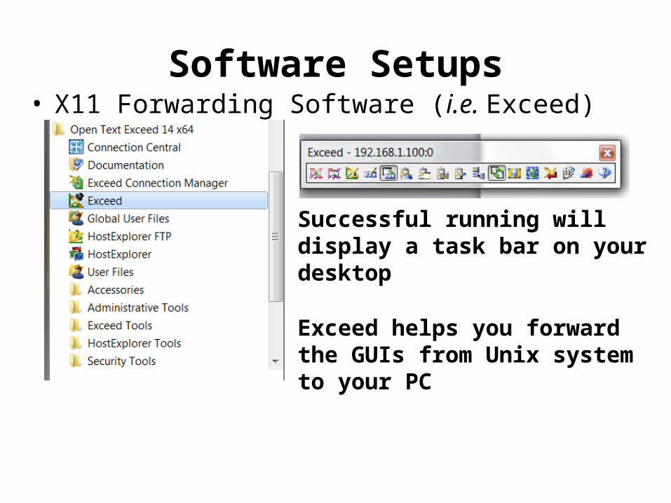
Software Setups• X11 Forwarding Software (i.e. Exceed)
Successful running will display a task bar on your desktop
Exceed helps you forward the GUIs from Unix system to your PC
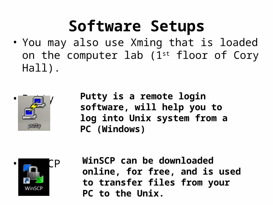
Software Setups• You may also use Xming that is loaded on the
computer lab (1st floor of Cory Hall).
• Putty
• WinSCP
Putty is a remote login software, will help you to log into Unix system from a PC (Windows)
WinSCP can be downloaded online, for free, and is used to transfer files from your PC to the Unix.
Servers and Performance• Instructional servers (login with the instructional
accounts): pulsar.eecs.berkeley.edu quasar.eecs.berkeley.edu c199.eecs.berkeley.edu• Shared servers are going to be slow, due to the
multiple-thread tasking. Do not wait until the last day!• For those who want to WFH: The connection speed is
going to be slow, if you are off campus and do the direct forwarding from the servers.
My suggestion: leave a computer on campus running Sentaurus and remote log into it.
Configurations• .cshrc file A system configuration file under your folder, to define
all the environmental variables needed in Unix system Append the following codes to the bottom of your
existing .cshrc file:
• X11 Forwarding Make sure you have enabled the X11 forwarding
option in putty.
setenv LM_LICENSE_FILE [email protected] path = ($path /usr/eesww/synopsys/G_2012.06/bin)setenv STDB $HOME/SYNOPSYS/STDB
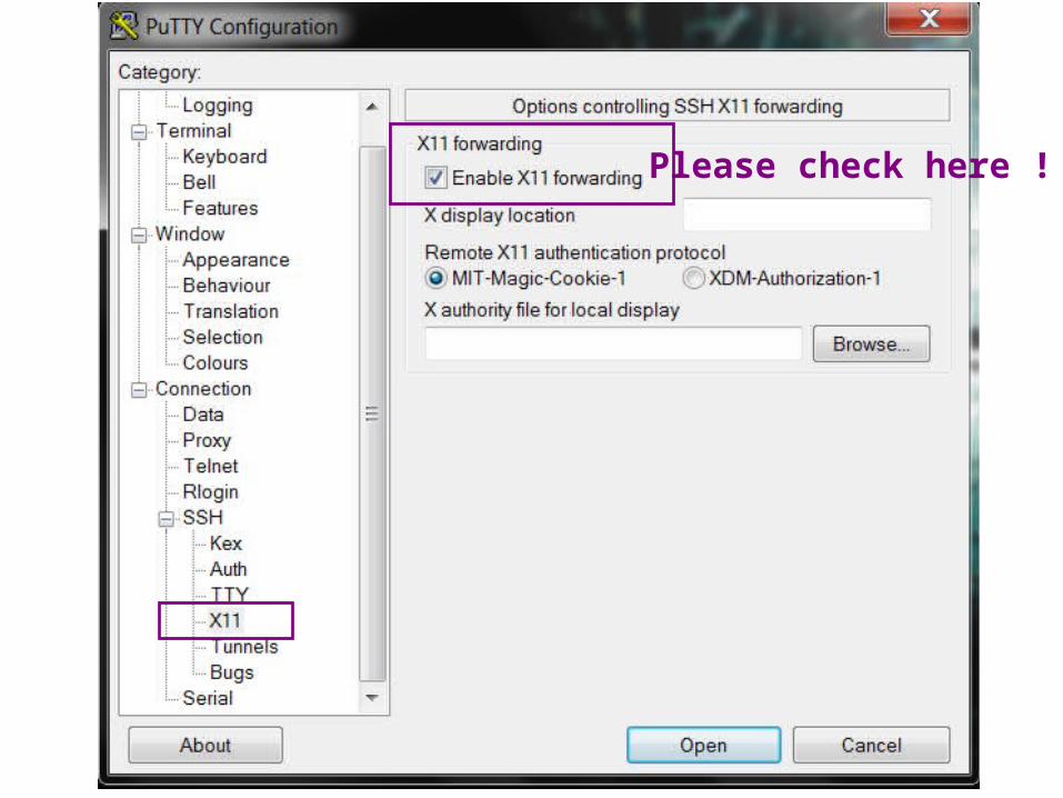
Please check here !
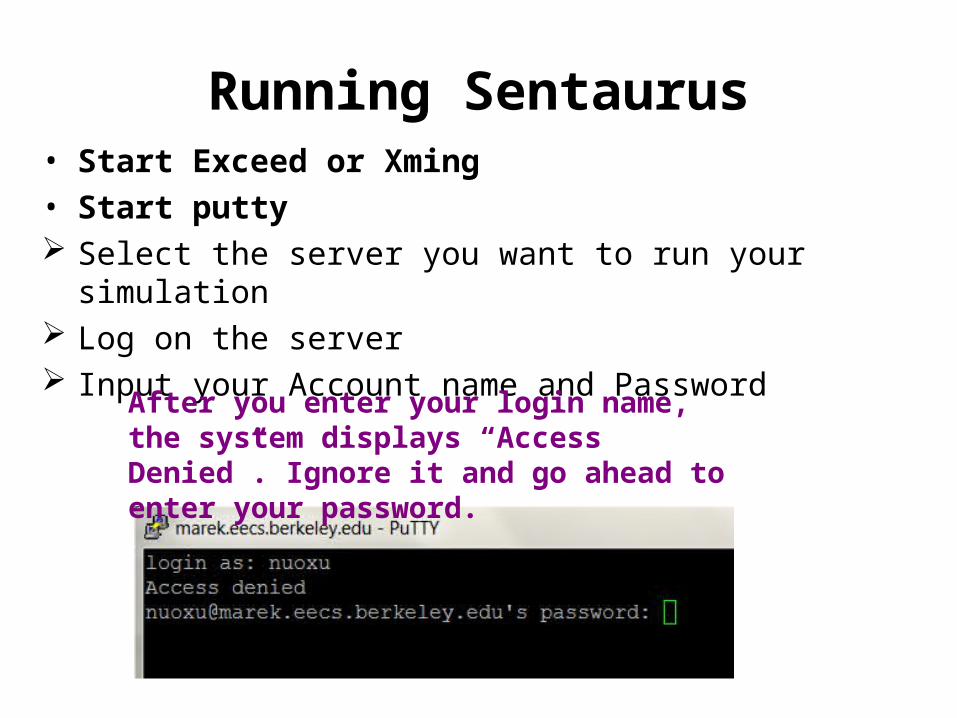
Running Sentaurus• Start Exceed or Xming• Start putty Select the server you want to run your simulation Log on the server Input your Account name and Password
After you enter your login name, the system displays “Access Denied”. Ignore it and go ahead to enter your password.
Transfer of Project Folder to Unix
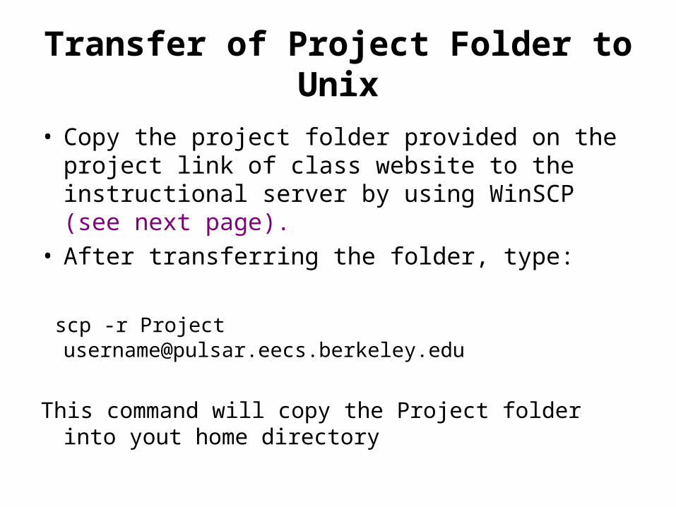
• Copy the project folder provided on the project link of class website to the instructional server by using WinSCP (see next page).
• After transferring the folder, type:
scp -r Project [email protected]
This command will copy the Project folder into yout home directory
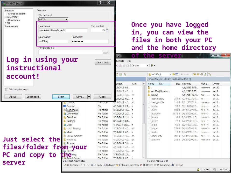
Log in using your instructional account!
Once you have logged in, you can view the files in both your PC and the home directory of the server
Just select the files/folder from your PC and copy to the server
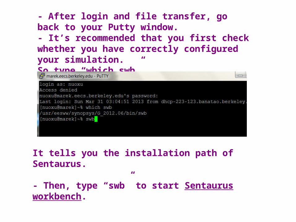
- After login and file transfer, go back to your Putty window.- It’s recommended that you first check whether you have correctly configured your simulation.So type “which swb”
It tells you the installation path of Sentaurus.
- Then, type “swb” to start Sentaurus workbench.
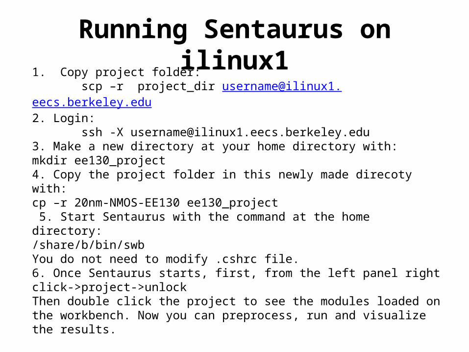
Running Sentaurus on ilinux11. Copy project folder: scp –r project_dir [email protected]. Login: ssh -X [email protected]. Make a new directory at your home directory with:mkdir ee130_project4. Copy the project folder in this newly made direcoty with:cp –r 20nm-NMOS-EE130 ee130_project 5. Start Sentaurus with the command at the home directory:/share/b/bin/swbYou do not need to modify .cshrc file. 6. Once Sentaurus starts, first, from the left panel right click->project->unlockThen double click the project to see the modules loaded on the workbench. Now you can preprocess, run and visualize the results.
For Windows: •install MobaXterm from http://mobaxterm.mobatek.net/. On MobaXterm, you have a unix like command line using which you can login using the same unix like commands as above.
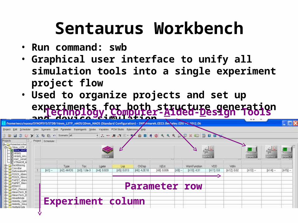
Sentaurus Workbench• Run command: swb• Graphical user interface to unify all simulation tools
into a single experiment project flow• Used to organize projects and set up experiments
for both structure generation and device simulation
Technology Computer-Aided-Design Tools
Parameter row
Experiment column
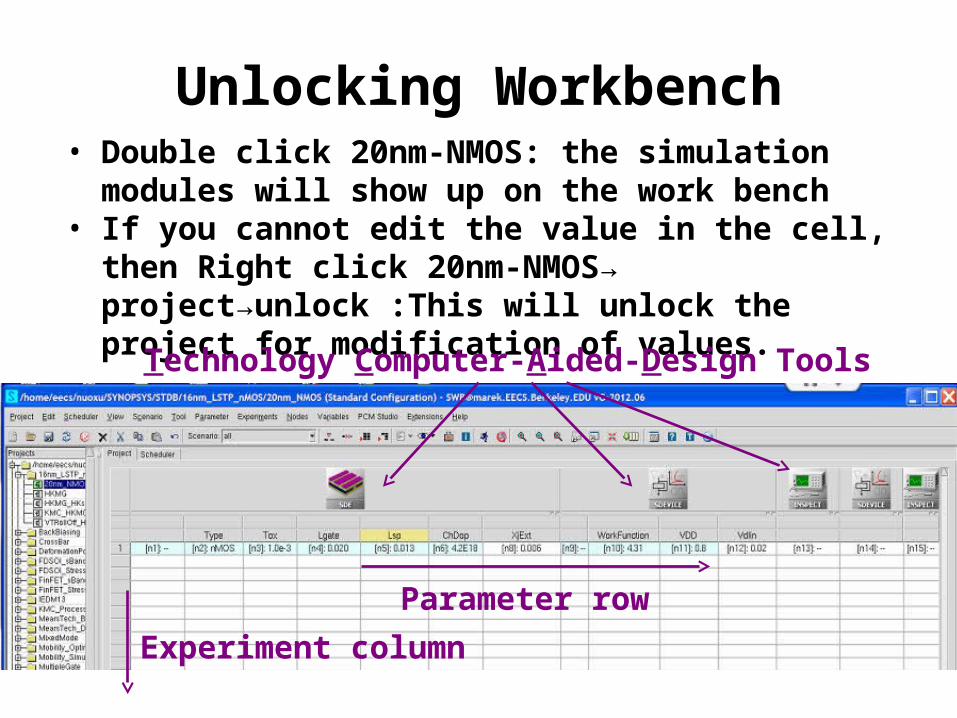
Unlocking Workbench• Double click 20nm-NMOS: the simulation modules
will show up on the work bench• If you cannot edit the value in the cell, then Right
click 20nm-NMOS→ project→unlock :This will unlock the project for modification of values.
Technology Computer-Aided-Design Tools
Parameter row
Experiment column
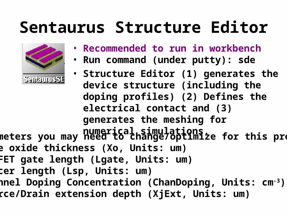
Sentaurus Structure Editor• Recommended to run in workbench• Run command (under putty): sde• Structure Editor (1) generates the device
structure (including the doping profiles) (2) Defines the electrical contact and (3) generates the meshing for numerical simulations.
Parameters you may need to change/optimize for this project•Gate oxide thickness (Xo, Units: um)•MOSFET gate length (Lgate, Units: um)•Spacer length (Lsp, Units: um)•Channel Doping Concentration (ChanDoping, Units: cm-3)•Source/Drain extension depth (XjExt, Units: um)
Sentaurus Device• Recommended to run in workbench• Run command (under putty): sdevice• Sentaurus Device simulates the device
performance by solving multiple, coupled physical equations based on the meshing.
• Inputs: gate voltage (Vgs), drain voltage (Vds), workfunction value
Common Physical models:•Si band structure (Ec/v, Nc/v and bandgap narrowing)•Fermi-Dirac Statistics•Poisson equation, continuity equation•Band-to-band tunneling, R-G current•Drift-Diffusion current, carrier mobility, velocity saturation
Sentaurus Inspect• Recommended to run in workbench• Used to automatically extract critical
device performance parameters such as:Vt_lin Id_linVt_sat Id_sat I_OFF
• Also used to plot the Id-Vg and Id-Vd curves
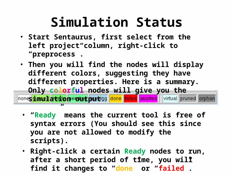
Simulation Status• Start Sentaurus, first select from the left project
column, right-click to “preprocess”.
• Then you will find the nodes will display different colors, suggesting they have different properties. Here is a summary. Only colorful nodes will give you the simulation output.
• “Ready” means the current tool is free of syntax errors (You should see this since you are not allowed to modify the scripts).
• Right-click a certain Ready nodes to run, after a short period of time, you will find it changes to “done” or “failed”.
Basic Operations for Sentaurus Structure Editor
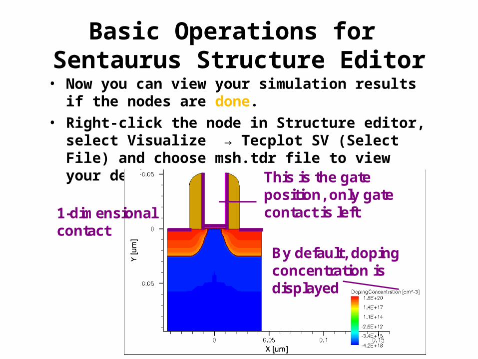
• Now you can view your simulation results if the nodes are done.
• Right-click the node in Structure editor, select Visualize → Tecplot SV (Select File) and choose msh.tdr file to view your device structure.
This is the gate position, only gate contact is left1-dimensional
contact
By default, doping concentration is displayed
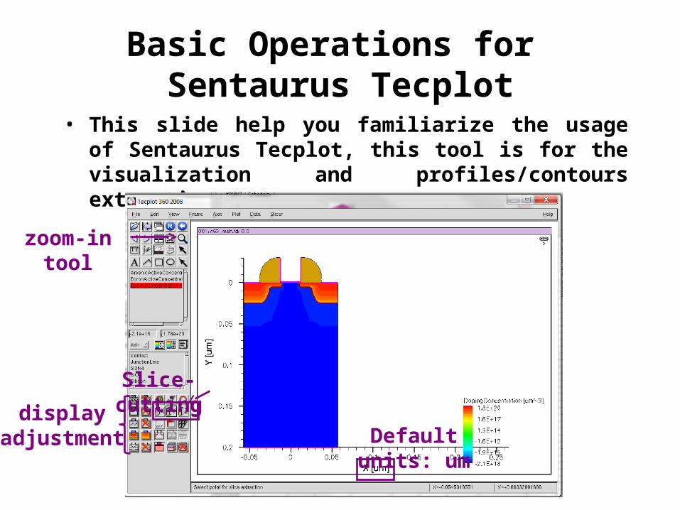
Basic Operations for Sentaurus Tecplot
• This slide help you familiarize the usage of Sentaurus Tecplot, this tool is for the visualization and profiles/contours extraction purposes.
zoom-in tool
display adjustment
Slice-cutting
Default units: um
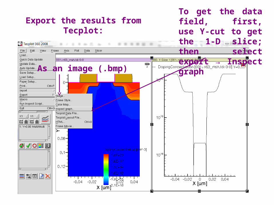
Export the results from Tecplot:
As an image (.bmp)
To get the data field, first, use Y-cut to get the 1-D slice; then select export → Inspect graph
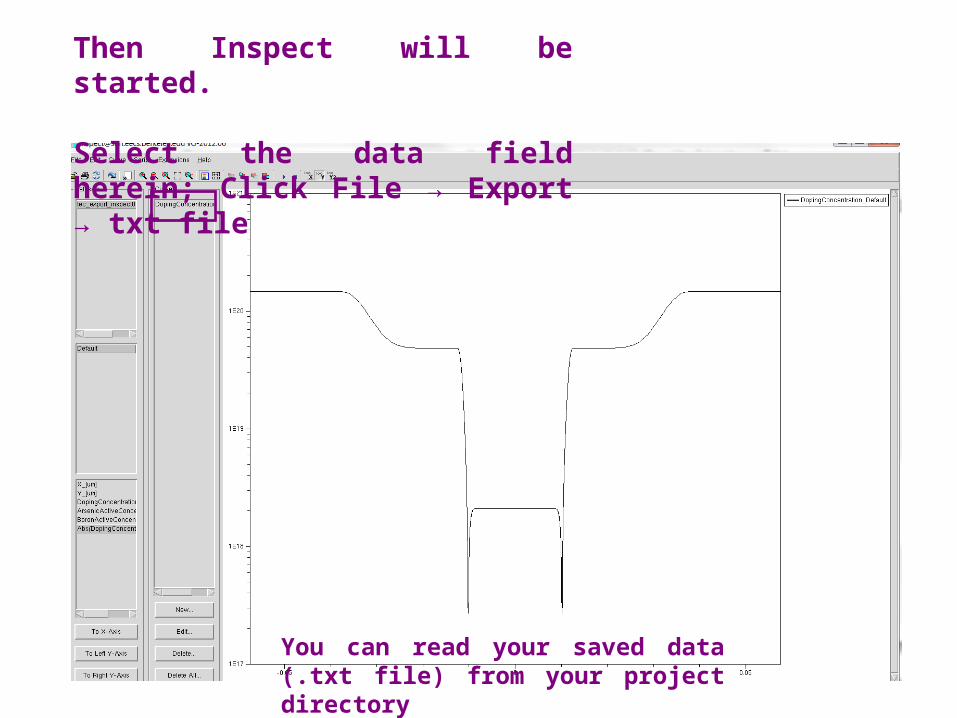
Then Inspect will be started.
Select the data field herein; Click File → Export → txt file
You can read your saved data (.txt file) from your project directory
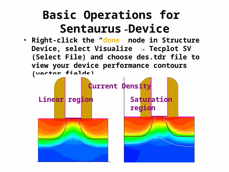
Basic Operations for Sentaurus Device
• Right-click the “done” node in Structure Device, select Visualize → Tecplot SV (Select File) and choose des.tdr file to view your device performance contours (vector fields).
Linear region Saturation region
Current Density
Basic Operations for Sentaurus Device Cont.’d
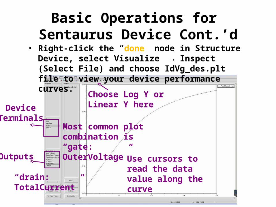
• Right-click the “done” node in Structure Device, select Visualize → Inspect (Select File) and choose IdVg_des.plt file to view your device performance curves.
Choose Log Y or Linear Y here
Use cursors to read the data value along the curve
Most common plot combination is “gate: OuterVoltage”
“drain: TotalCurrent”
Device Terminals
Outputs
Project Tips
• Typical Performance Figure-of-Merits
• Performance Specifications for this Project
• Performance Optimization Hints for a Short-Channel MOSFET
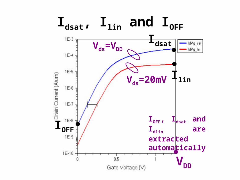
Idsat, Ilin and IOFF
VDD
IOFF
Idsat
Ilin
Vds=VDD
Vds=20mV
IOFF, Idsat and Idlin are extracted automatically
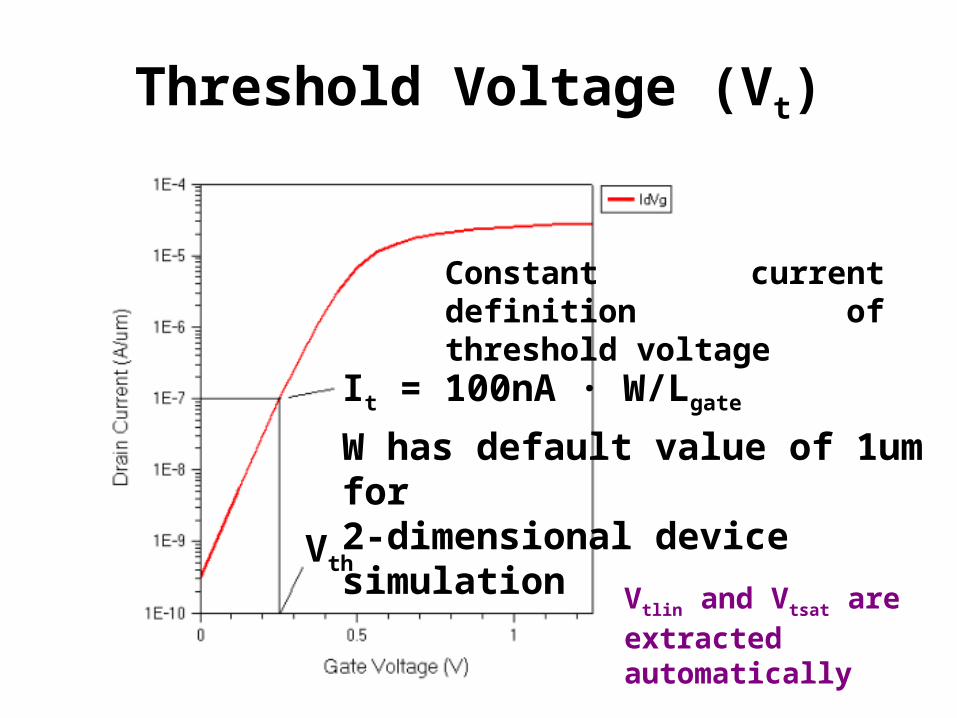
Threshold Voltage (Vt)
Constant current definition of threshold voltage
Vth
It = 100nA · W/Lgate
W has default value of 1um for 2-dimensional device simulation
Vtlin and Vtsat are extracted automatically
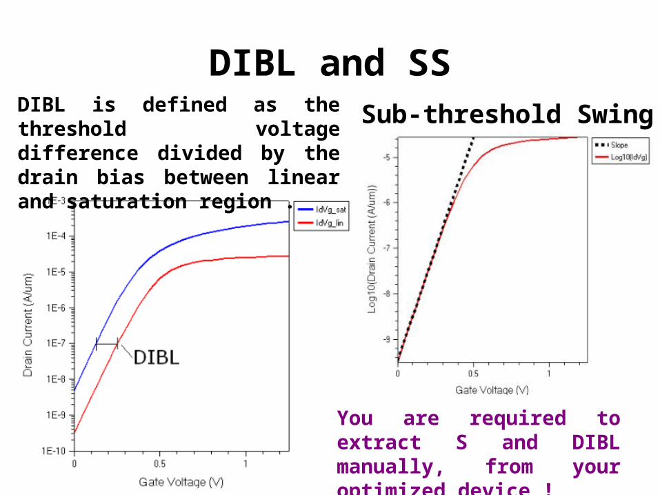
DIBL and SSSub-threshold SwingDIBL is defined as the threshold
voltage difference divided by the drain bias between linear and saturation region .
You are required to extract S and DIBL manually, from your optimized device !
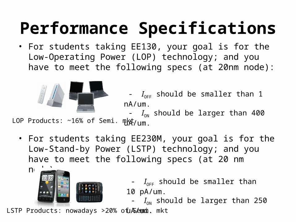
Performance Specifications• For students taking EE130, your goal is for the Low-Operating
Power (LOP) technology; and you have to meet the following specs (at 20nm node):
• For students taking EE230M, your goal is for the Low-Stand-by Power (LSTP) technology; and you have to meet the following specs (at 20 nm node):
LOP Products: ~16% of Semi. mkt
LSTP Products: nowadays >20% of Semi. mkt
- IOFF should be smaller than 1 nA/um. - ION should be larger than 400 uA/um.
- IOFF should be smaller than 10 pA/um. - ION should be larger than 250 uA/um.

Hints for Your Optimizations• Impacts of channel doping concentration (Nch): Increasing
Nch generally helps to reduce IOFF, until it touches the band-to-band tunneling limits. On the other hand, high Nch will degrade the carrier mobility values, resulting in a low ION.
• Impacts of Junction Depth (Xj): smaller extension Xj helps to reduce IOFF, however it will result in a larger Source/Drain series resistance value to degrade ION.
• Impacts of SiN spacer width (Lsp): Wider spacer helps to reduce the impact from deep Source/Drain regions; however it will also result in the larger series resistance problem.
So as you can see, there exist trade-offs to optimize ION/IOFF ☺
Project Hints• Since our performance targets are mainly for ION and IOFF,
so you should start working on the saturation-region device simulation first.
• Once you are able to meet the specs, then you should perform the linear-region device simulation to get the current and threshold voltage values, as well as to measure the DIBL value.

Project Hints (Con’d)• The next task is to study the Short-Channel Effect, by
changing the gate length ONLY. Perform the simulations in both linear and saturation regions, and then plot the threshold voltage values vs. gate length.
Refer to Lecture 22, Slide 12.
• Lastly, you should run the last SDevice component, to generate the Ids vs. Vds curves under 4 Vgs values. Then take a look at the I-V curves to decide whether your device performance is limited by the “pinch-off” or the carrier velocity saturation.
How to determine this? Refer to Lecture 22 Slide 10

Q&A
Please - come to Dr. Xu’s office hours (Mon 12-1PM & Tue 3-4PM) OR - send him emails ([email protected]) OR - Post a question note on Piazzafor any technical issues/problems.