sentaurus workbench - jmbussat/physics290e/fall-2006/... · sentaurus workbench contents iii...
TRANSCRIPT
Sentaurus WorkbenchVersion Y-2006.06, June 2006

ii
Copyright Notice and Proprietary InformationCopyright © 2006 Synopsys, Inc. All rights reserved. This software and documentation contain confidential and proprietary information that is the property of Synopsys, Inc. The software and documentation are furnished under a license agreement and may be used or copied only in accordance with the terms of the license agreement. No part of the software and documentation may be reproduced, transmitted, or translated, in any form or by any means, electronic, mechanical, manual, optical, or otherwise, without prior written permission of Synopsys, Inc., or as expressly provided by the license agreement.
Right to Copy DocumentationThe license agreement with Synopsys permits licensee to make copies of the documentation for its internal use only. Each copy shall include all copyrights, trademarks, service marks, and proprietary rights notices, if any. Licensee must assign sequential numbers to all copies. These copies shall contain the following legend on the cover page:
“This document is duplicated with the permission of Synopsys, Inc., for the exclusive use of __________________________________________ and its employees. This is copy number __________.”
Destination Control StatementAll technical data contained in this publication is subject to the export control laws of the United States of America. Disclosure to nationals of other countries contrary to United States law is prohibited. It is the reader’s responsibility to determine the applicable regulations and to comply with them.
DisclaimerSYNOPSYS, INC., AND ITS LICENSORS MAKE NO WARRANTY OF ANY KIND, EXPRESS OR IMPLIED, WITH REGARD TO THIS MATERIAL, INCLUDING, BUT NOT LIMITED TO, THE IMPLIED WARRANTIES OF MERCHANTABILITY AND FITNESS FOR A PARTICULAR PURPOSE.
Registered Trademarks (®)Synopsys, AMPS, Arcadia, C Level Design, C2HDL, C2V, C2VHDL, Cadabra, Calaveras Algorithm, CATS, CRITIC, CSim, Design Compiler, DesignPower, DesignWare, EPIC, Formality, HSIM, HSPICE, Hypermodel, iN-Phase, in-Sync, Leda, MAST, Meta, Meta-Software, ModelTools, NanoSim, OpenVera, PathMill, Photolynx, Physical Compiler, PowerMill, PrimeTime, RailMill, RapidScript, Saber, SiVL, SNUG, SolvNet, Superlog, System Compiler, TetraMAX, TimeMill, TMA, VCS, Vera, and Virtual Stepper are registered trademarks of Synopsys, Inc.
Trademarks (™)Active Parasitics, AFGen, Apollo, Apollo II, Apollo-DPII, Apollo-GA, ApolloGAII, Astro, Astro-Rail, Astro-Xtalk, Aurora, AvanTestchip, AvanWaves, BCView, Behavioral Compiler, BOA, BRT, Cedar, ChipPlanner, Circuit Analysis, Columbia, Columbia-CE, Comet 3D, Cosmos, CosmosEnterprise, CosmosLE, CosmosScope, CosmosSE, Cyclelink, Davinci, DC Expert, DC Professional, DC Ultra, DC Ultra Plus, Design Advisor, Design Analyzer, Design Vision, DesignerHDL, DesignTime, DFM-Workbench, Direct RTL, Direct Silicon Access, Discovery, DW8051, DWPCI, Dynamic-Macromodeling, Dynamic Model Switcher, ECL Compiler, ECO Compiler, EDAnavigator, Encore, Encore PQ, Evaccess, ExpressModel, Floorplan Manager, Formal Model Checker, FoundryModel, FPGA Compiler II, FPGA Express, Frame Compiler, Galaxy, Gatran, HANEX, HDL Advisor, HDL Compiler, Hercules, Hercules-Explorer, Hercules-II, Hierarchical Optimization Technology, High Performance Option, HotPlace, HSIMplus, HSPICE-Link, iN-Tandem, Integrator, Interactive Waveform Viewer, i-Virtual Stepper, Jupiter, Jupiter-DP, JupiterXT, JupiterXT-ASIC, JVXtreme, Liberty, Libra-Passport, Library Compiler, Libra-Visa, Magellan, Mars, Mars-Rail, Mars-Xtalk, Medici, Metacapture, Metacircuit, Metamanager, Metamixsim, Milkyway, ModelSource, Module Compiler, MS-3200, MS-3400, Nova Product Family, Nova-ExploreRTL, Nova-Trans, Nova-VeriLint, Nova-VHDLlint, Optimum Silicon, Orion_ec, Parasitic View, Passport, Planet, Planet-PL, Planet-RTL, Polaris, Polaris-CBS, Polaris-MT, Power Compiler, PowerCODE, PowerGate, ProFPGA, ProGen, Prospector, Protocol Compiler, PSMGen, Raphael, Raphael-NES, RoadRunner, RTL Analyzer, Saturn, ScanBand, Schematic Compiler, Scirocco, Scirocco-i, Shadow Debugger, Silicon Blueprint, Silicon Early Access, SinglePass-SoC, Smart Extraction, SmartLicense, SmartModel Library, Softwire, Source-Level Design, Star, Star-DC, Star-MS, Star-MTB, Star-Power, Star-Rail, Star-RC, Star-RCXT, Star-Sim, Star-SimXT, Star-Time, Star-XP, SWIFT, Taurus, TimeSlice, TimeTracker, Timing Annotator, TopoPlace, TopoRoute, Trace-On-Demand, True-Hspice, TSUPREM-4, TymeWare, VCS Express, VCSi, Venus, Verification Portal, VFormal, VHDL Compiler, VHDL System Simulator, VirSim, and VMC are trademarks of Synopsys, Inc.
Service Marks (SM)MAP-in, SVP Café, and TAP-in are service marks of Synopsys, Inc.
SystemC is a trademark of the Open SystemC Initiative and is used under license.ARM and AMBA are registered trademarks of ARM Limited.All other product or company names may be trademarks of their respective owners.
Sentaurus Workbench, Y-2006.06
SENTAURUS WORKBENCH CONTENTS
Sentaurus WorkbenchAbout this manual ................................................................................................................................ ix
Audience ............................................................................................................................................................. ixRelated publications.............................................................................................................................................xTypographic conventions .....................................................................................................................................xCustomer support................................................................................................................................................ xi
Chapter 1 Overview...............................................................................................................................1Introduction ..........................................................................................................................................................1Sentaurus Workbench projects ............................................................................................................................2Compatibility with previous versions ....................................................................................................................2Projects browser ..................................................................................................................................................2
Viewing trees..................................................................................................................................................3Multiple roots ..................................................................................................................................................3Updating the view...........................................................................................................................................3
Project Editor........................................................................................................................................................4Toolbar buttons ..............................................................................................................................................4Projects browser.............................................................................................................................................6Project tab ......................................................................................................................................................6
Scheduler .............................................................................................................................................................6Scheduler tab .................................................................................................................................................6
Batch tools ...........................................................................................................................................................7gpp .................................................................................................................................................................7spp..................................................................................................................................................................7gsub................................................................................................................................................................7gjob.................................................................................................................................................................7gcleanup.........................................................................................................................................................8gtclsh ..............................................................................................................................................................8
Chapter 2 Managing projects ...............................................................................................................9Creating a project or folder...................................................................................................................................9Opening a project.................................................................................................................................................9Copying a project ...............................................................................................................................................10Saving a project, Save As, and Save Clean As .................................................................................................10Moving a project or folder...................................................................................................................................11
Drag-and-drop operation ..............................................................................................................................11Cut-and-paste operation...............................................................................................................................11
Deleting a project or folder .................................................................................................................................12Renaming a project or folder..............................................................................................................................12Opening a Web-based project ...........................................................................................................................13Project documentation .......................................................................................................................................13
Chapter 3 Project view........................................................................................................................15View configuration..............................................................................................................................................15Configuring the column width.............................................................................................................................16Showing tool names and database tools ...........................................................................................................17Family Tree view ................................................................................................................................................17Experimental Plan view......................................................................................................................................19Parameter Values view ......................................................................................................................................19Variable Values view..........................................................................................................................................19Real and virtual family nodes .............................................................................................................................19Viewing node output files ...................................................................................................................................20Copying table parts to other tools ......................................................................................................................21
iii

SENTAURUS WORKBENCHCONTENTS
Exporting a spreadsheet ....................................................................................................................................21Exporting spreadsheet to spreadsheet viewer .............................................................................................21Exporting spreadsheet to Inspect.................................................................................................................22
Viewing Sentaurus Workbench and Optimizer system log files .........................................................................22Visualizing response surfaces............................................................................................................................22Scheduler view...................................................................................................................................................23
Viewing running nodes in projects................................................................................................................23Configuring user queues ..............................................................................................................................23Configuring project queues ..........................................................................................................................24Configuring DMW queues ............................................................................................................................24Editing queue files ........................................................................................................................................25
Chapter 4 Editing projects..................................................................................................................27Undoing changes ...............................................................................................................................................27Tools ..................................................................................................................................................................27
Adding tools..................................................................................................................................................27Deleting tools................................................................................................................................................30Changing tool properties ..............................................................................................................................30Editing tool input files ...................................................................................................................................30Importing files ...............................................................................................................................................31Viewing tool database information ...............................................................................................................31
Parameters.........................................................................................................................................................32Adding parameters .......................................................................................................................................32Deleting parameters .....................................................................................................................................33Changing parameter properties....................................................................................................................34Removing parameter values ........................................................................................................................34
Variables ............................................................................................................................................................35Defining global variables ..............................................................................................................................35Changing variable properties .......................................................................................................................36Deleting variables.........................................................................................................................................36Formatting variables.....................................................................................................................................36Defining variables per node..........................................................................................................................37Changing and deleting variable values at a node ........................................................................................37
Using PCM library to evaluate PCM variables ...................................................................................................38Nodes.................................................................................................................................................................41
Viewing and editing properties of nodes ......................................................................................................41Experiments and scenarios................................................................................................................................42
Adding experiments......................................................................................................................................42Deleting experiments....................................................................................................................................43Sorting experiments .....................................................................................................................................44Importing experiments from a file .................................................................................................................44Viewing experiment properties .....................................................................................................................45Adding scenarios..........................................................................................................................................46Deleting scenarios........................................................................................................................................46Copying and moving experiments between scenarios .................................................................................46Copying and moving experiments between projects....................................................................................46Pruning and unpruning .................................................................................................................................47Locking nodes ..............................................................................................................................................47Quick-running nodes ....................................................................................................................................48
iv

SENTAURUS WORKBENCH CONTENTS
Chapter 5 Design-of-experiments and Taguchi wizards .................................................................49Design-of-experiments (DoE) Wizard ................................................................................................................49
Screening .....................................................................................................................................................51Response surface model..............................................................................................................................51Stochastic design .........................................................................................................................................52Square design ..............................................................................................................................................53User-defined parameters..............................................................................................................................53Final step......................................................................................................................................................54
Taguchi Wizard ..................................................................................................................................................54
Chapter 6 Preprocessing projects.....................................................................................................59Global and run-time preprocessing ....................................................................................................................59Preprocessor #-commands ................................................................................................................................60@-references and tree navigation......................................................................................................................61Node filters .........................................................................................................................................................62Node expressions ..............................................................................................................................................62Split points..........................................................................................................................................................62Preprocessed variables......................................................................................................................................63Extracted variables.............................................................................................................................................64Execution dependencies ....................................................................................................................................66Tcl command blocks ..........................................................................................................................................66
Creating Tcl command blocks ......................................................................................................................66Tcl preprocessing .........................................................................................................................................68Tcl blocks and Sentaurus Workbench variables ..........................................................................................69Input and output operations inside Tcl command blocks .............................................................................69Summary of rules for using Tcl command blocks.........................................................................................70When to use Tcl command blocks ...............................................................................................................71
Chapter 7 Running projects ...............................................................................................................73From the Project Editor ......................................................................................................................................73From the command line .....................................................................................................................................74Preprocessing ....................................................................................................................................................76Aborting projects ................................................................................................................................................77Aborting nodes ...................................................................................................................................................77Viewing log or history files..................................................................................................................................78Project summary ................................................................................................................................................78
Chapter 8 Cleaning up projects .........................................................................................................81Cleaning up projects ..........................................................................................................................................81Cleaning up the output of nodes ........................................................................................................................82Cleaning up projects from the command line.....................................................................................................82
Chapter 9 Configuring Sentaurus Workbench .................................................................................85Configuring preferences.....................................................................................................................................85Tool databases...................................................................................................................................................88
Delimiters of a tool database file ..................................................................................................................89Tool DB Editor ..............................................................................................................................................91
Graphical user interface ........................................................................................................................91File Types..............................................................................................................................................92Tools .....................................................................................................................................................92Input Editors ..........................................................................................................................................95Output Viewers .....................................................................................................................................96Create New Tool DB File ......................................................................................................................96
v

SENTAURUS WORKBENCHCONTENTS
Edit Cleanup Patterns ...........................................................................................................................97Open With Text Editor...........................................................................................................................99
Chapter 10 Remote computing ........................................................................................................101Using remote computing ..................................................................................................................................101
Chapter 11 Integrating Sentaurus Workbench with other tools ...................................................103Visualizing response surfaces..........................................................................................................................103Taurus Workbench to Sentaurus Workbench converter ..................................................................................106
Restrictions.................................................................................................................................................107
Chapter 12 Reference guide.............................................................................................................109System requirements and setup ......................................................................................................................109
Sentaurus Workbench options ...................................................................................................................109Sentaurus Workbench menus..........................................................................................................................110
Project menu ..............................................................................................................................................110Edit menu ...................................................................................................................................................111Scheduler menu .........................................................................................................................................112View menu..................................................................................................................................................113Scenario menu ...........................................................................................................................................114Tool menu ..................................................................................................................................................114Parameter menu.........................................................................................................................................115Experiments menu .....................................................................................................................................115Nodes menu ...............................................................................................................................................116Variables menu ..........................................................................................................................................117Optimization menu .....................................................................................................................................117Calibration menu ........................................................................................................................................118Extensions menu........................................................................................................................................118Help menu ..................................................................................................................................................118Keyboard navigation keys ..........................................................................................................................119
Preprocessor and reference syntax .................................................................................................................119@-references and tree navigation ..............................................................................................................119#-commands...............................................................................................................................................121Split commands..........................................................................................................................................123Node expressions.......................................................................................................................................124
Schedulers .......................................................................................................................................................125Scheduling systems ...................................................................................................................................125DMW Scheduler .........................................................................................................................................126
Host database .....................................................................................................................................127Constraint database/queues ...............................................................................................................128Host allocation policy ..........................................................................................................................128Troubleshooting DMW ........................................................................................................................129
LSF Scheduler............................................................................................................................................130Configuring the scheduling system ............................................................................................................131
Global queue configuration file............................................................................................................131HostDB (for DMW) ..............................................................................................................................134Tool associations ................................................................................................................................134
Sentaurus Workbench files ..............................................................................................................................136Project files.................................................................................................................................................136User configuration files...............................................................................................................................137Global configuration files ............................................................................................................................137Typical input and output files......................................................................................................................137
vi

SENTAURUS WORKBENCH CONTENTS
Appendix A DMW Scheduler: Frequently asked questions ..........................................................139Limitations of Sentaurus Workbench ...............................................................................................................139Requirements for using DMW in a network......................................................................................................139Global queue and global host database files ...................................................................................................140Administrator: Setting up DMW queues ...........................................................................................................140User: Setting up user queues and project queues ...........................................................................................141User: Excluding a specific host and running on a specific set of hosts............................................................141Checking the DMWUmpire...............................................................................................................................142Standard tests to troubleshoot a particular machine in the DMW network ......................................................143Using ssh and DMW Scheduler together .........................................................................................................144
vii

SENTAURUS WORKBENCHCONTENTS
viii

SENTAURUS WORKBENCH ABOUT THIS MANUAL
Sentaurus Workbench
About this manual
Sentaurus Workbench is the primary graphical front end for the integration of Sentaurus simulationsoftware into one environment.
Sentaurus Workbench is a software package that provides a convenient framework to design, organize,and automatically run complete TCAD simulation projects. It provides users with a graphical userinterface to drive a variety of Synopsys simulation and visualization tools and other third-party tools,and to automate the execution of fully parameterized projects. Sentaurus Workbench also supportsdesign-of-experiments, extraction and analysis of results, optimization, and uncertainty analysis. It hasan integrated job scheduler to speed up simulations and takes full advantage of distributed,heterogeneous, and corporate computing resources.
The main chapters are:
Chapter 1 gives an overview of Sentaurus Workbench.
Chapter 2 presents information for managing projects in Sentaurus Workbench.
Chapter 3 describes how to alter the viewing configuration of projects in Sentaurus Workbench.
Chapter 4 describes how projects can be edited.
Chapter 5 describes the design-of-experiments (DoE) and Taguchi wizards.
Chapter 6 presents information about preprocessing projects.
Chapter 7 discusses how to run projects in Sentaurus Workbench.
Chapter 8 discusses how to clean up projects.
Chapter 9 describes how to configure Sentaurus Workbench.
Chapter 10 discusses how to use remote computing from Sentaurus Workbench.
Chapter 11 provides information about how to use other tools from Sentaurus Workbench.
Chapter 12 is a reference guide.
AudienceThis manual is intended for users of the Sentaurus Workbench software package.
ix

SENTAURUS WORKBENCHABOUT THIS MANUAL
Related publicationsFor additional information about Sentaurus Workbench, see:
The documentation installed with the Sentaurus Workbench software and available through theSentaurus Workbench Help menu.
The Sentaurus Workbench release notes, available on SolvNet (see Accessing SolvNet on page xi).
Documentation on the Web, which is available through SolvNet athttps://solvnet.synopsys.com/DocsOnWeb.
Synopsys Online Documentation (SOLD), which is included with the software for CD users or isavailable to download through the Synopsys Electronic Software Transfer (EST) system.
Typographic conventionsConvention Explanation
[ ] Brackets
Blue text Identifies a cross-reference (only on the screen).
Bold text Identifies a selectable icon, button, menu, or tab. It also indicates the name of a field, window, dialog box, or panel.
Courier font Identifies text that is displayed on the screen or that the user must type. It identifies the names of files, directories, paths, parameters, keywords, and variables.
Italicized text Used for emphasis, the titles of books and journals, and non-English words. It also identifies components of an equation or a formula, a placeholder, or an identifier.
Key+Key Indicates keyboard actions, for example, Ctrl+I (press the I key while pressing the Control key).
Menu > Command Indicates a menu command, for example, File > New (from the File menu, select New).
NOTE Identifies important information.
x

SENTAURUS WORKBENCH ABOUT THIS MANUAL
Customer supportCustomer support is available through SolvNet online customer support and through contacting theSynopsys Technical Support Center.
Accessing SolvNet
SolvNet includes an electronic knowledge base of technical articles and answers to frequently askedquestions about Synopsys tools. SolvNet also gives you access to a wide range of Synopsys onlineservices including software downloads, documentation on the Web, and “Enter a Call to the SupportCenter.”
To access SolvNet:
1. Go to the SolvNet Web page at http://solvnet.synopsys.com.
2. If prompted, enter your user name and password. (If you do not have a Synopsys user name andpassword, follow the instructions to register with SolvNet.)
If you need help using SolvNet, click HELP in the top-right menu bar or in the footer.
Contacting the Synopsys Technical Support Center
If you have problems, questions, or suggestions, you can contact the Synopsys Technical Support Centerin the following ways:
Open a call to your local support center from the Web by going to http://solvnet.synopsys.com(Synopsys user name and password required), then clicking “Enter a Call to the Support Center.”
Send an e-mail message to your local support center:
• E-mail [email protected] from within North America.
• Find other local support center e-mail addresses at http://www.synopsys.com/support/support_ctr.
Telephone your local support center:
• Call (800) 245-8005 from within the continental United States.
• Call (650) 584-4200 from Canada.
• Find other local support center telephone numbers at http://www.synopsys.com/support/support_ctr.
xi

SENTAURUS WORKBENCHABOUT THIS MANUAL
Contacting your local TCAD Support Team directly
Send an e-mail message to:
[email protected] from within North America and South America.
[email protected] from within Europe.
[email protected] from within Asia Pacific (China, Taiwan, Singapore, Malaysia,India, Australia).
[email protected] from Korea.
[email protected] from Japan.
xii
SENTAURUS WORKBENCH CHAPTER 1 OVERVIEW
Sentaurus Workbench
CHAPTER 1 Overview
This chapter provides an overview of Sentaurus Workbench.
IntroductionSentaurus Workbench is the Synopsys framework designed to make the use of Synopsys TCAD toolseasier. It frees the user from typing system commands for the handling of data files or startingapplications. One of its main advantages over a traditional simulation session is the possibility ofparameterizing input files to run simulation groups automatically. The main features of the SentaurusWorkbench framework include:
Intuitive graphical user interface (GUI) with functionality that simplifies the editing and handlingof complex simulation projects
Organization of simulations into projects and folders provides a clear overview of the overallsimulation environment
Project database is mapped to the underlying, native file systems and allows robust file managementin a multiuser, distributed environment
Tool flow with multiple instances of the same tool
Simulation parameters can be used in any input file; the resulting simulation experiments can beedited before running the simulations
Scenarios-to-group simulation experiments
Design-of-experiments (DoE), optimization, and statistical analysis can be performed
Scheduler within same GUI to schedule and monitor the running of simulation projects
Access to two back end batch systems to run large simulations in parallel on a network ofworkstations
Extensive collection of example projects that can be copied and modified as required
Flexible open tool interface makes it possible to plug in third-party tools
The Sentaurus Workbench framework has one graphical application consisting of two tabs for theProject Editor (Project tab) and the Scheduler (Scheduler tab), and batch tools (gpp, spp, gsub, gjob,gcleanup, and gtclsh).
1

SENTAURUS WORKBENCHCHAPTER 1 OVERVIEW
Sentaurus Workbench projectsA project consists of a family of scenarios. Each scenario consists of a family of experiments wherecertain sensible input variables take different values. Parameters can be introduced at any point in thesimulation flow, from the process to the device simulation phases. A parameterized project isrepresented as a tree structure, the so-called Family Tree, which is derived from a simulation flow anda combination of all the parameter values. Each level in the Family Tree corresponds to a simulationphase, as defined in the simulation flow.
To distinguish between real and virtual simulation phases: real phases correspond to the execution oftool instances, and virtual phases are introduced by parameters and do not lead to any tool execution. Ina real simulation phase, there are as many tool instances as nodes in the corresponding tree level. Eachtool instance is characterized by a combination of parameter values that defines the path from the rootnode to the tool instance node.
In the Family Tree, each node has a unique number – the node key (<nkey>). A real node represents theend of a simulation phase and holds the output of the corresponding tool instance. Sentaurus Workbenchassociates output to a node by adding the prefix n<nkey>_ to all of the output file names of the tool used.
In physical form, a project exists as a directory in the file system. The directory contains a .project filethat indicates to the Sentaurus Workbench framework that the current directory is a project directory.
Compatibility with previous versionsSentaurus Workbench is designed to be backward compatible. Old projects can be loaded, edited, andrun by Sentaurus Workbench. All necessary conversions are made automatically by SentaurusWorkbench.
Sentaurus Workbench is not forward compatible, that is, it is not possible to edit new projects withearlier versions of the software. However, for a smooth conversion to Sentaurus Workbench, there is away to save a new project using the old naming scheme, in order to use it with earlier versions (seeSaving a project, Save As, and Save Clean As on page 10).
Projects browserProjects are managed in the projects browser, which has a Windows Explorer–like appearance andlayout. The projects browser is organized like a tree, with the leaves of the tree being the projectdirectories. The tree displays the current file system under the STDB setting. Project directories can thenbe attached to the window.
2
SENTAURUS WORKBENCH CHAPTER 1 OVERVIEW
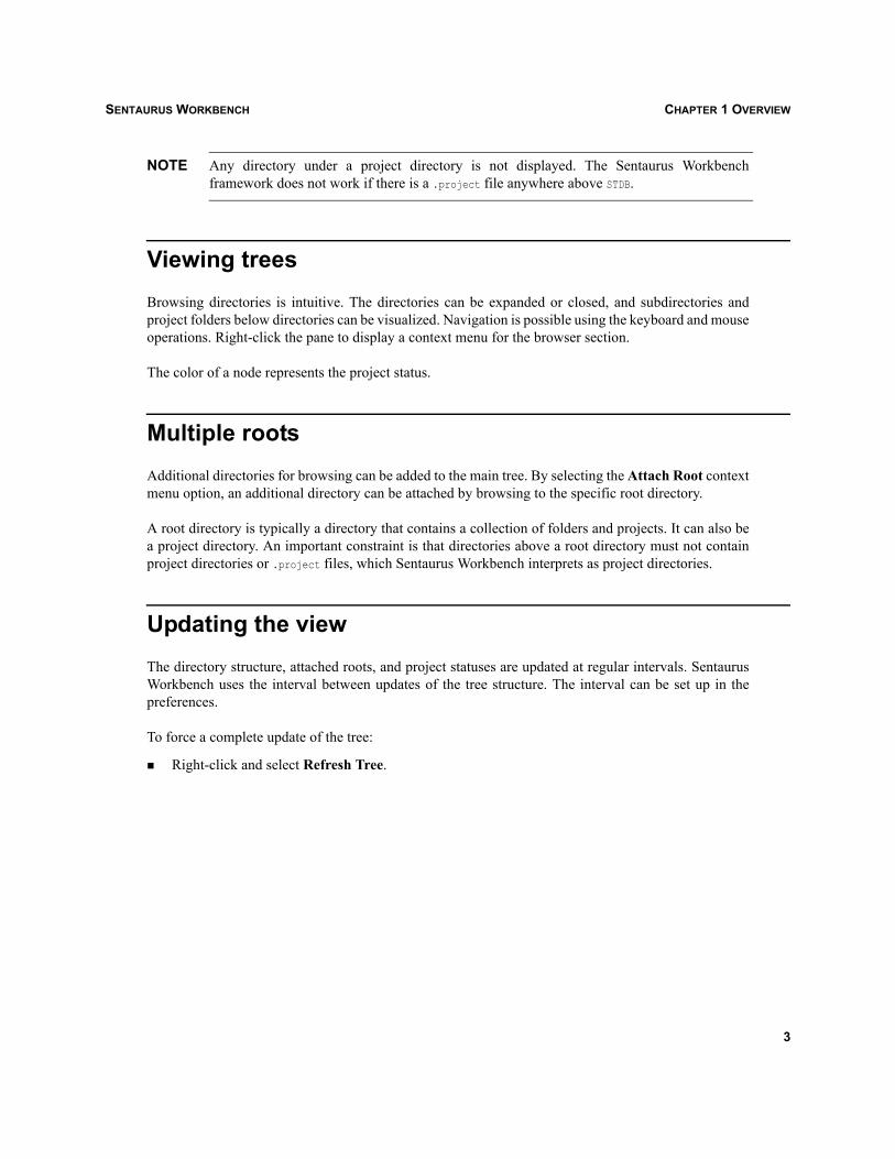
NOTE Any directory under a project directory is not displayed. The Sentaurus Workbenchframework does not work if there is a .project file anywhere above STDB.
Viewing treesBrowsing directories is intuitive. The directories can be expanded or closed, and subdirectories andproject folders below directories can be visualized. Navigation is possible using the keyboard and mouseoperations. Right-click the pane to display a context menu for the browser section.
The color of a node represents the project status.
Multiple rootsAdditional directories for browsing can be added to the main tree. By selecting the Attach Root contextmenu option, an additional directory can be attached by browsing to the specific root directory.
A root directory is typically a directory that contains a collection of folders and projects. It can also bea project directory. An important constraint is that directories above a root directory must not containproject directories or .project files, which Sentaurus Workbench interprets as project directories.
Updating the viewThe directory structure, attached roots, and project statuses are updated at regular intervals. SentaurusWorkbench uses the interval between updates of the tree structure. The interval can be set up in thepreferences.
To force a complete update of the tree:
Right-click and select Refresh Tree.
3
SENTAURUS WORKBENCHCHAPTER 1 OVERVIEW
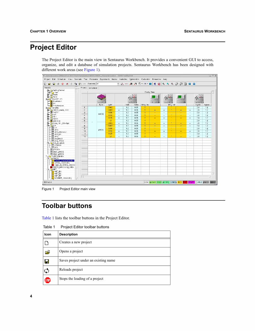
Project EditorThe Project Editor is the main view in Sentaurus Workbench. It provides a convenient GUI to access,organize, and edit a database of simulation projects. Sentaurus Workbench has been designed withdifferent work areas (see Figure 1).
Figure 1 Project Editor main view
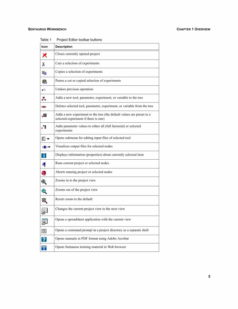
Toolbar buttonsTable 1 lists the toolbar buttons in the Project Editor.
Table 1 Project Editor toolbar buttons
Icon Description
Creates a new project
Opens a project
Saves project under an existing name
Reloads project
Stops the loading of a project
4
SENTAURUS WORKBENCH CHAPTER 1 OVERVIEW
Closes currently opened project
Cuts a selection of experiments
Copies a selection of experiments
Pastes a cut or copied selection of experiments
Undoes previous operation
Adds a new tool, parameter, experiment, or variable to the tree
Deletes selected tool, parameter, experiment, or variable from the tree
Adds a new experiment to the tree (the default values are preset to a selected experiment if there is one)
Adds parameter values to either all (full factorial) or selected experiments
Opens submenu for editing input files of selected tool
Visualizes output files for selected nodes
Displays information (properties) about currently selected item
Runs current project or selected nodes
Aborts running project or selected nodes
Zooms in to the project view
Zooms out of the project view
Resets zoom to the default
Changes the current project view to the next view
Opens a spreadsheet application with the current view
Opens a command prompt in a project directory as a separate shell
Opens manuals in PDF format using Adobe Acrobat
Opens Sentaurus training material in Web browser
Table 1 Project Editor toolbar buttons
Icon Description
5

SENTAURUS WORKBENCHCHAPTER 1 OVERVIEW
Projects browserIn the left pane of Figure 1 on page 4, the projects browser shows a global view of the project databaseof the user as a hierarchy of folders and projects. It features a tree representation to navigate through thishierarchy, to open and close folders, and to load projects, and for diverse operations on entire projectsand folders, such as copying and moving projects.
Project tabThe Project tab in the right pane of Figure 1 shows an individual project as a table of experiments andsimulation results. The rows from left to right represent the simulation flow followed by extractedresults. The simulation flow is the sequence of tools running the simulations steps, split by parameters.Columns represent different experiments and their corresponding parameter and variable values. Theuser can add, remove, and modify experiments, and control the running of experiments.
SchedulerThe Scheduler is used to schedule and monitor the running of simulation jobs of a project. It providesusers with an overview of the jobs that are running and their distribution on the local area network. Italso allows users to submit and abort jobs, and to define scheduling queues and job mapping constraints.
To open the Scheduler:
Scheduler > Show Scheduler or click the Scheduler tab.
Figure 2 Scheduler main view
Scheduler tabIn Figure 2, the right pane shows the Scheduler tab, which displays a table of running jobs with differentscheduling information, such as running time and running host. Only jobs belonging to the selectedproject or folder are shown. Individual jobs can also be aborted.
6

SENTAURUS WORKBENCH CHAPTER 1 OVERVIEW
Batch tools
gppThe batch tool gpp is the preprocessor of Sentaurus Workbench. It prepares a project for execution. Itsgoals are to:
Calculate an optimum execution graph from the simulation tree to take advantage of parallelcomputing while enforcing start–completion job interdependencies.
Generate actual tool input files from user-provided templates to differentiate experiments.
NOTE The batch tool gpp has been replaced by a new and faster preprocessor (see spp). FromSentaurus Workbench Version Y-2006.06, spp is specified as the default preprocessor. Tocontinue to use gpp, specify the path to the gpp binary in the user preferences and set theenvironment variable NEW_PP to 0.
sppThe batch tool spp is the new preprocessor of Sentaurus Workbench and replaces gpp. The advantages ofspp are its speed and the possibility to process @-character expressions that are supported by simulatorssuch as TSUPREM-4.
NOTE Since spp has all of the functions that apply to gpp, any examples using gpp in this manual canalso be applied to spp.
gsubThe batch tool gsub consists of a simple command to submit jobs to the scheduler for execution. It alsoconstitutes the interface of Sentaurus Workbench to different internal or external batch systems.
gjobThe batch tool gjob manages the execution of each individual job. It controls the evaluation of the jobprologue and epilogue, and the running of the corresponding simulation tool.
7

SENTAURUS WORKBENCHCHAPTER 1 OVERVIEW
gcleanupThe batch tool gcleanup is a useful utility to clean up a project from the command line. All operationsincluding the renumbering of the tree can be performed using this tool.
gtclshThe batch tool gtclsh is a tool command language (Tcl) shell that has been extended with all of theinternal commands of the Sentaurus Workbench framework, such as tree manipulation.
8
SENTAURUS WORKBENCH CHAPTER 2 MANAGING PROJECTS
Sentaurus Workbench
CHAPTER 2 Managing projects
This chapter describes the operations that can be performed on the projects and directories by using theprojects browser.
Creating a project or folderTo create a project:
Project > New > New Project.
To create a folder:
1. Select the folder in which a new folder is to be created.
2. Project > New > New Folder, or right-click and select New Folder.
3. Type the name of the new folder.
4. Press the Return key.
The new folder is saved.
NOTE It is not possible to create new folders inside projects.
Opening a projectTo open a project from the browser:
Double-click the project in the tree.
Alternatively:
1. Browse through the tree and select the project to be opened.
2. Press the Return key, or double-click the selection, or right-click and select Open.
The project opens in the main view.
9

SENTAURUS WORKBENCHCHAPTER 2 MANAGING PROJECTS
Copying a projectTo copy a project:
1. Browse through the tree and select the project to be copied.
2. Copy the selection by using Ctrl+C, or right-click and select Copy.
3. Browse to the required destination folder or keep the selection.
4. Paste the selection by using Ctrl+V, or right-click and select Paste.
NOTE Projects (and folders) cannot be copied inside other projects.
NOTE If the project is being pasted over the original project, the new project is created in the samefolder with ‘Copy_of_’ before the project name. If the folder is being pasted over the originalfolder, the new folder together with all its content is created in the same parent folder with‘Copy_of_’ before the folder name.
Saving a project, Save As, and Save Clean AsTo save the current project in the same directory:
Project > Save or Ctrl+S.
To save a project with a different name or in a different directory:
Project > Save As.
All the contents of the project directory is copied to the new directory, and the project is saved.
To save time and omit copying all of the preprocessed and node output files:
Project > Save Clean As.
To create a new project on the basis of selected experiments:
Project > Save Selected Experiments As.
To create a new project on the basis of selected experiments, but without copying the simulation results:
Project > Save Selected Experiments Clean As.
10
SENTAURUS WORKBENCH CHAPTER 2 MANAGING PROJECTS
To save a Sentaurus Workbench project in a previously used format, select the Pre-Sentaurus SaveMode option. With this option, Sentaurus Workbench saves the project using the old namingconventions.
NOTE With this release of Sentaurus Workbench, changes to the naming conventions for tools andfiles have been introduced. Several new tools have been incorporated into SentaurusWorkbench and some previously used tools have been renamed. A project saved withSentaurus Workbench will not load into earlier versions of the software, unless the optionPre-Sentaurus Save Mode is selected on saving.
Moving a project or folderThere are two methods for moving projects and folders across directories.
Drag-and-drop operation1. Browse through the tree and select the project or folder to be moved.
2. Drag the project or folder to the destination project or folder.
Cut-and-paste operation1. Browse through the tree and select the project or folder to be moved.
2. Cut the selection by using Ctrl+X, or right-click and select Cut.
3. Browse to the destination project or folder.
4. Paste the selection by using Ctrl+V, or right-click and select Paste.
Note the following:
Projects opened in the browser or projects that are running cannot be moved.
Folders with any open or running project cannot be moved.
Projects or folders cannot be placed inside projects.
Projects without write permission are copied.
11

SENTAURUS WORKBENCHCHAPTER 2 MANAGING PROJECTS
Deleting a project or folderTo delete a project or folder:
1. Browse through the tree and select the project or folder to be deleted.
2. Edit > Delete, or right-click and select Delete.
NOTE This operation irrecoverably removes the project directory.
Renaming a project or folderTo rename a project or folder:
1. Browse through the tree and select the project or folder to be renamed.
2. Right-click and select Rename.
3. Type the new name.
4. Press the Return key. (The new name is saved.)
NOTE Locked projects cannot be renamed or deleted.To unlock a project, open the project and Project > Unlock.
NOTE The operations on the tree directly act on the file system. Therefore, any delete, move, orrename operation cannot be undone.
NOTE A file name can only contain characters permitted by the operating system. Even though thebrowser is configured to identify all illegal names and characters, with extreme file names, itis likely to cause some unpredictable behavior and may result in a loss of work.
12

SENTAURUS WORKBENCH CHAPTER 2 MANAGING PROJECTS
Opening a Web-based projectSentaurus Workbench offers the functionality to open gzip’ed projects stored at a Web location.Sentaurus Workbench supports HyperText Transfer Protocol (HTTP).
For example, to access a gzip’ed project located at http://www.apage.com/project.gzp, the user can typethis address in the URL field of the Open a Web Project dialog box. Sentaurus Workbench retrievesthe project from the location, downloads it to a temporary directory, and opens the project for viewing.
Figure 3 Open a Web Project dialog box
NOTE If the user utilizes a proxy server, the proxy configurations can be set in the user preferences.HTTP proxy is supported.
Project documentationA documentation file can be attached to a project. The file format must be PDF and the file name shouldbe greadme.pdf. The file can contain any information concerning the project.
To open a project documentation file in Adobe Acrobat Reader:
1. Select a project in the projects browser.
2. Project > Documentation.
13

SENTAURUS WORKBENCHCHAPTER 2 MANAGING PROJECTS
14

SENTAURUS WORKBENCH CHAPTER 3 PROJECT VIEW
Sentaurus Workbench
CHAPTER 3 Project view
This chapter describes how to alter the viewing configuration of projects in Sentaurus Workbench.
View configurationThe project view consists of four sections: Family Tree, Experimental Plan, Parameter Values, andVariable Values. These sections can be switched on and off independently by selecting the appropriateoptions in the View menu.
Figure 4 Different parts of the project view
NOTE The default view options, that is, the sections that are visible when Sentaurus Workbenchstarts, can be configured in the preferences (see Configuring preferences on page 85).
15

SENTAURUS WORKBENCHCHAPTER 3 PROJECT VIEW
Configuring the column widthSentaurus Workbench can ‘remember’ the column width for the next project loadings. This feature isswitched off by default.
To switch on the feature:
View > Column Width > Remember Column Width.
It can be switched on for all sessions of Sentaurus Workbench in preferences (F12 key). If this option isswitched on, the current column widths are saved in the column configuration file when saving a projector when explicitly using View > Column Width > Save Column Width.
NOTE When the Remember Column Width option is selected, the column widths are notautomatically adjusted to the project data.
To change the column width, drag the vertical line of the column.
To show hidden columns or to hide columns:
View > Column Width > Show/Hide Columns or Ctrl+F6 (see Figure 5).
To show all columns and restore their widths to the project default:
View > Column Width > Restore Column Width or F6.
Figure 5 Show/Hide Columns dialog box
16

SENTAURUS WORKBENCH CHAPTER 3 PROJECT VIEW
Showing tool names and database toolsThe tool icons show only the database tool name at the bottom of each icon. It is possible to see the toolname as rollover text. This feature is switched off by default.
To switch on the feature:
View > Tree Options > Show Tool Names.
It can be switched on for all sessions of Sentaurus Workbench in the preferences (F12 key).
Family Tree viewTo switch on or off the tree view:
View > Show Tree or F1.
The Family Tree view shows the simulations in Sentaurus Workbench. The horizontally shownsimulation flow is the backbone of any project. It defines the sequence of tools and parameters involvedin simulations. Each parameter belongs to a tool. The experiments are shown vertically. The cells areexpanded to represent a tree view, with the cells themselves being either virtual or nonvirtual tree nodesassociated with individual simulations.
Figure 6 Family Tree view
Figure 6 shows the main parts of the Family Tree view of Sentaurus Workbench. The different areas are:
Tool row Contains all of the tools of the project.
Tool name row Contains all of the tool names used in the project. Set Default View Options >Tool Names in a Row to true in the user preferences and reload the project.
Parameter row Contains all of the parameters of the project.
Experiments column Contains all of the experiments, which are numbered.
Tool Row
Tool Name RowParameter Row
Expe
rimen
ts
Tool Flow with Parameter Splits
17

SENTAURUS WORKBENCHCHAPTER 3 PROJECT VIEW
The tree view can be changed to display information about the node or from the node status files. Theshortcut keys Ctrl+1 to Ctrl+6 allow users to switch between multiple views:
Parameter Values View > Tree Options > Parameter Values or Ctrl+1Displays the parameter values of the loaded project.
Node Numbers View > Tree Options > Node Numbers or Ctrl+2 Displays the node numbers.
Host View > Tree Options > Host or Ctrl+3Displays the last host on which the node was run.
Date View > Tree Options > Date or Ctrl+4Displays the time when the last run of the node was completed.
Execution Time View > Tree Options > Execution Time or Ctrl+5Displays the time taken for the last run of the node or an error message.
Variables View > Tree Options > Variables or Ctrl+6Displays the variables associated with the nodes.
NOTE To change views sequentially, click .
Figure 7 Family Tree host view
18
SENTAURUS WORKBENCH CHAPTER 3 PROJECT VIEW
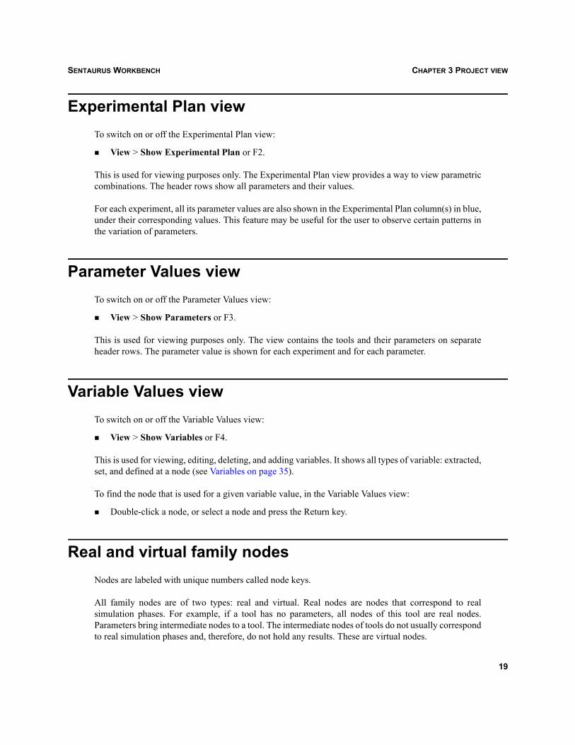
Experimental Plan viewTo switch on or off the Experimental Plan view:
View > Show Experimental Plan or F2.
This is used for viewing purposes only. The Experimental Plan view provides a way to view parametriccombinations. The header rows show all parameters and their values.
For each experiment, all its parameter values are also shown in the Experimental Plan column(s) in blue,under their corresponding values. This feature may be useful for the user to observe certain patterns inthe variation of parameters.
Parameter Values viewTo switch on or off the Parameter Values view:
View > Show Parameters or F3.
This is used for viewing purposes only. The view contains the tools and their parameters on separateheader rows. The parameter value is shown for each experiment and for each parameter.
Variable Values viewTo switch on or off the Variable Values view:
View > Show Variables or F4.
This is used for viewing, editing, deleting, and adding variables. It shows all types of variable: extracted,set, and defined at a node (see Variables on page 35).
To find the node that is used for a given variable value, in the Variable Values view:
Double-click a node, or select a node and press the Return key.
Real and virtual family nodesNodes are labeled with unique numbers called node keys.
All family nodes are of two types: real and virtual. Real nodes are nodes that correspond to realsimulation phases. For example, if a tool has no parameters, all nodes of this tool are real nodes.Parameters bring intermediate nodes to a tool. The intermediate nodes of tools do not usually correspondto real simulation phases and, therefore, do not hold any results. These are virtual nodes.
19

SENTAURUS WORKBENCHCHAPTER 3 PROJECT VIEW
However, tools with split capabilities such as Sentaurus Process, Sentaurus Device, and Dios can createreal intermediate nodes (see Split points on page 62).
Real nodes are colored according to the execution status of the corresponding tool instance. Virtualnodes are white. The color codes in the status bar of the main window show the meaning of each color.For more information about a simulation detail, double-click the corresponding node or press the Enterkey.
NOTE Sentaurus Workbench shows the real status of intermediate nodes if the option View > TreeOptions > Check Virtual Nodes is selected. Otherwise, all intermediate nodes will be shownas virtual ones, that is, they will be white. By default, this option is switched off each timeSentaurus Workbench starts. The default setting can be changed through the user preferences(Edit > User Preferences) or by pressing the F12 key. In the user preferences, Table >Default View Options > Check Virtual Nodes should be selected.
Viewing node output filesFor each real family node, there can be several output files that can be viewed by using visualizationtools.
To view the output files of a node:
1. Select a node or nodes in the Project tab.
2. Click the visualize button in the toolbar.
All visualization tools are made available for the selected nodes.
NOTE The visualization tools and the maximum number of files are configured in the tool database.
Alternatively, to make all visualization tools available:
Nodes > Visualize.
If no output files correspond to a particular node, there is the option of opening a tool that has no files.
20
SENTAURUS WORKBENCH CHAPTER 3 PROJECT VIEW
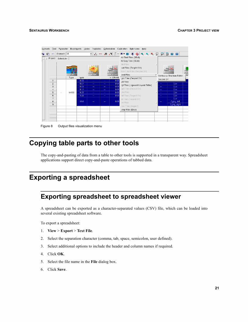
Figure 8 Output files visualization menu
Copying table parts to other toolsThe copy-and-pasting of data from a table to other tools is supported in a transparent way. Spreadsheetapplications support direct copy-and-paste operations of tabbed data.
Exporting a spreadsheet
Exporting spreadsheet to spreadsheet viewerA spreadsheet can be exported as a character-separated values (CSV) file, which can be loaded intoseveral existing spreadsheet software.
To export a spreadsheet:
1. View > Export > Text File.
2. Select the separation character (comma, tab, space, semicolon, user defined).
3. Select additional options to include the header and column names if required.
4. Click OK.
5. Select the file name in the File dialog box.
6. Click Save.
21
SENTAURUS WORKBENCHCHAPTER 3 PROJECT VIEW
To open spreadsheet software with the current view:
View > Export > Run Spreadsheet Application or click .
This saves the current view to a temporary text file and loads it with a spreadsheet application that isconfigured in the user preferences (Miscellaneous > Spreadsheet Application).
Exporting spreadsheet to InspectA spreadsheet can be exported for viewing in Inspect.
To export a spreadsheet:
1. View > Export > Plot File.
2. Select the file name in the File dialog box.
3. Click Save.
To open Inspect with the current view:
View > Export > Run Inspect.
This saves the current view to a temporary plot file and loads it into Inspect.
Viewing Sentaurus Workbench and Optimizer system log files
The preprocessor and project log files for projects of Sentaurus Workbench can be viewed using:
Project > Logs > Preprocessor or Project > Logs > Project.
To view Optimizer log files:
Optimization > View Log.
Visualizing response surfacesSee Visualizing response surfaces on page 103.
22

SENTAURUS WORKBENCH CHAPTER 3 PROJECT VIEW
Scheduler view
Viewing running nodes in projectsAll the running nodes that belong to the running projects under STDB are listed. The status of nodes isupdated based on the refresh frequency setting.
Configuring user queuesUser-level tool queue assignments (see Tool associations on page 134) can be modified using Scheduler> Configure Queues > User Queues. Users can modify the tool queue assignments and put in specificoptions associated with the Scheduler.
Figure 9 Configure User Queues dialog box
23

SENTAURUS WORKBENCHCHAPTER 3 PROJECT VIEW
Configuring project queuesProject-level tool queue assignments (see Tool associations on page 134) can be modified usingScheduler > Configure Queues > Project Queues. Users can modify the tool queue assignments, andthese assignments are applied only to a particular project.
Figure 10 Configure Project Queues dialog box
Configuring DMW queuesDMW queues are easily configured for user and project levels. The GUI provides a list of availablequeues and a list of available tools. Each queue has a set of hosts defined by the systems administrator.Users can assign the tools to a particular queue. If users need to exclude hosts, these hosts can bedeselected.
DMW queues can be configured for user-level and project-level tool queue associations (see DMWScheduler on page 126).
To create DMW user tool associations:
Scheduler > Configure Queues > User DMW Queues.
24

SENTAURUS WORKBENCH CHAPTER 3 PROJECT VIEW
To create DMW project tool associations:
Scheduler > Configure Queues > Project DMW Queues.
Figure 11 Configure DMW User Queues dialog box
Editing queue filesThe Scheduler does not provide a GUI to add node constraints for user-level or project-level queues.Therefore, the only way to add node constraints is by manually editing the user queue or project queuefiles.
To edit user queues:
Scheduler > Configure Queues > Edit User Queues.
To edit project queues:
Scheduler > Configure Queues > Edit Project Queues.
25

SENTAURUS WORKBENCHCHAPTER 3 PROJECT VIEW
26

SENTAURUS WORKBENCH CHAPTER 4 EDITING PROJECTS
Sentaurus Workbench
CHAPTER 4 Editing projects
This chapter describes how projects can be edited in Sentaurus Workbench. A project can be edited onlyif it is in edit mode, that is, it is in a disk-writable area, is not locked, and is not running (see Chapter 2on page 9).
Undoing changesTo undo a change:
Edit > Undo or Ctrl+Z.
NOTE Only tree modifications can be undone. Modified or deleted input or output files cannot berestored.
The ‘undo’ data is not released after saving the project.
To free the ‘undo’ data:
Project > Cleanup (see Chapter 8 on page 81).
ToolsTools are, in general, TCAD simulation tools. Other tools may be available depending on theconfiguration of the tool databases of Sentaurus Workbench (see Tool databases on page 88).
NOTE There can be multiple instances of the same tool in the simulation flow.
Adding toolsIn a new project, to add the first tool to the flow:
1. Tool > Add.
2. Type a unique tool instance name.
3. Select the tool from the list of available tools.
27

SENTAURUS WORKBENCHCHAPTER 4 EDITING PROJECTS
4. Type command-line options.
5. If applicable, select the Use Ligament option, and enter Ligament command-line options.
6. Click OK.A dialog box is displayed as shown in Figure 12. It appears if no experiments have been defined.
7. Click OK.
The default experiment is created.
Figure 12 Create Default Experiment dialog box
NOTE Ligament supports Sentaurus Process, Sentaurus Structure Editor, TSUPREM-4, and Dios.
To add subsequent tools:
1. Select a tool icon from the tool row.
2. Tool > Add or press the Insert key.The Add Tool dialog box is displayed (see Figure 13).
3. Type a unique tool instance name.
4. Select the database tool. Click the Tools button to select a tool from a graphical list of all availabletools (see Figure 14 on page 29).
5. Type command-line options.
6. If applicable, select the Use Ligament option.
7. Select the location of the new tool instance, before or after the selected tool.
8. Click OK to complete adding a tool or click Apply to add more tools.
Figure 13 Add Tool dialog box
28

SENTAURUS WORKBENCH CHAPTER 4 EDITING PROJECTS
Figure 14 List of all available database tools
NOTE Currently, Raphael NXT cannot be used in the Sentaurus Workbench tool flow forsimulations. Raphael NXT is a 3D capacitance extractor, which extracts capacitance of netsin large designs to better than 1% accuracy. Raphael NXT can be used by itself (stand-alonemode) or as part of Synopsys Star-RCXT. A distributed processing option is available withRaphael NXT that allows jobs to be run in parallel on a network of workstations with a near-linear increase in performance.
29

SENTAURUS WORKBENCHCHAPTER 4 EDITING PROJECTS
Deleting toolsTo delete a tool instance from the flow:
1. Select the required tool icon in the tool row.To select multiple tools, press the Ctrl key during selection.
2. Tool > Delete or press the Delete key.
If the tool to be deleted has parameters, the parameters can be assigned to the previous tool. To deleteparameters together with the tool, first delete the parameters.
NOTE When a tool is deleted, the corresponding tool input files are not deleted, which means thatthe changes can be undone (Edit > Undo). The file browser of Sentaurus Workbench can beused to delete the corresponding files (Project > File Browser).
Changing tool propertiesTo change tool properties:
1. Select the required tool in the tool row.
2. Tool > Properties or double-click the tool.
If the project is in edit mode, you can change the tool command-line options in the correspondingtext entry. Additionally, you can change the Ligament command-line options if applicable.
3. Click OK.
Editing tool input filesTo edit tool input files:
1. Select the required tool in the tool row.
2. Tool > Edit Input.
3. Select the file to edit from the submenu.The list of file types is taken from the tool databases (Edit > Tool DB).
If the user has writing permissions, the file can be edited. Otherwise, the file is read only.
30

SENTAURUS WORKBENCH CHAPTER 4 EDITING PROJECTS
Figure 15 Edit tool input file
Importing files
NOTE This operation is possible only for projects in edit mode.
To import a file:
1. Select the required tool in the tool row.
2. Tool > Import File.
3. Select the file to import.
4. Click Open.
NOTE This operation cannot be undone. The imported file replaces the current tool input file.
Viewing tool database informationTo view tool database information:
1. Select the required tool in the tool row.
2. Tool > Tool DB Info.
31

SENTAURUS WORKBENCHCHAPTER 4 EDITING PROJECTS
Figure 16 Tool database information dialog box
ParametersA parameter splits the flow at the insertion point to derive variations of the current tool. Each parameteris characterized by a unique name, a default value, and an arbitrary number of values. The purpose ofparameters is to create a family of similar simulations represented as a tree structure – the simulationtree – where levels from root to leaves (left to right) match the steps in the simulation flow.
Adding parametersParameters are part of a tool, so parameters can be added to existing tools only.
To add the first parameter to a flow with one tool:
1. Parameter > Add.
2. Type the name of the parameter.
3. Type the default value, which can be any alphanumeric value.
4. Click OK.
32
SENTAURUS WORKBENCH CHAPTER 4 EDITING PROJECTS
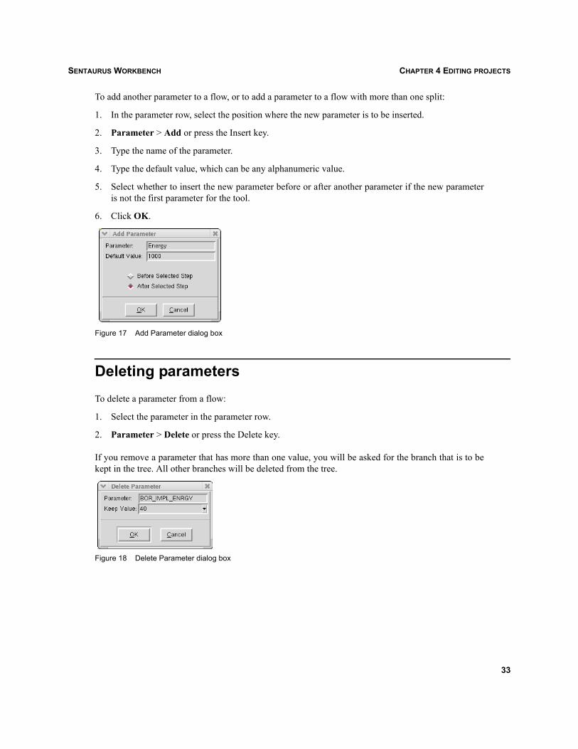
To add another parameter to a flow, or to add a parameter to a flow with more than one split:
1. In the parameter row, select the position where the new parameter is to be inserted.
2. Parameter > Add or press the Insert key.
3. Type the name of the parameter.
4. Type the default value, which can be any alphanumeric value.
5. Select whether to insert the new parameter before or after another parameter if the new parameteris not the first parameter for the tool.
6. Click OK.
Figure 17 Add Parameter dialog box
Deleting parametersTo delete a parameter from a flow:
1. Select the parameter in the parameter row.
2. Parameter > Delete or press the Delete key.
If you remove a parameter that has more than one value, you will be asked for the branch that is to bekept in the tree. All other branches will be deleted from the tree.
Figure 18 Delete Parameter dialog box
33

SENTAURUS WORKBENCHCHAPTER 4 EDITING PROJECTS
Changing parameter propertiesTo view or edit (in edit mode only) properties of a parameter:
1. Select the required parameter in the parameter row.
2. Parameter > Properties or double-click the parameter.
3. If the project is in edit mode, you can rename the parameter in the parameter text entry and changethe default value of the parameter in the default value text entry as required.
4. Click OK.
Figure 19 Parameter Properties dialog box
NOTE If a parameter name is changed, it is changed in the tree only. All references to that parameterin input files and variables are not changed.
Removing parameter valuesTo remove a parameter value (in edit mode only):
1. Select the required parameter in the parameter row.
2. Parameter > Remove Value.
3. Select the value to be removed.
4. Click OK.
Figure 20 Remove Parameter Value dialog box
34
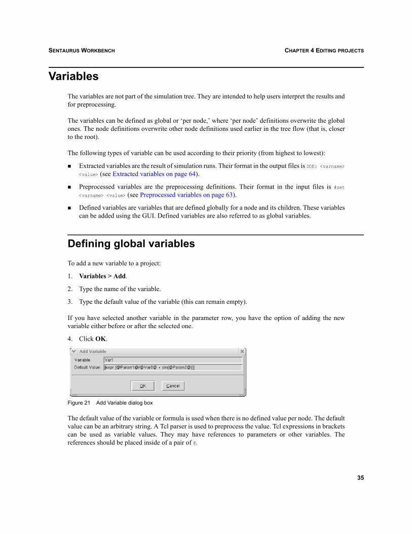
SENTAURUS WORKBENCH CHAPTER 4 EDITING PROJECTS
VariablesThe variables are not part of the simulation tree. They are intended to help users interpret the results andfor preprocessing.
The variables can be defined as global or ‘per node,’ where ‘per node’ definitions overwrite the globalones. The node definitions overwrite other node definitions used earlier in the tree flow (that is, closerto the root).
The following types of variable can be used according to their priority (from highest to lowest):
Extracted variables are the result of simulation runs. Their format in the output files is DOE: <varname>
<value> (see Extracted variables on page 64).
Preprocessed variables are the preprocessing definitions. Their format in the input files is #set<varname> <value> (see Preprocessed variables on page 63).
Defined variables are variables that are defined globally for a node and its children. These variablescan be added using the GUI. Defined variables are also referred to as global variables.
Defining global variablesTo add a new variable to a project:
1. Variables > Add.
2. Type the name of the variable.
3. Type the default value of the variable (this can remain empty).
If you have selected another variable in the parameter row, you have the option of adding the newvariable either before or after the selected one.
4. Click OK.
Figure 21 Add Variable dialog box
The default value of the variable or formula is used when there is no defined value per node. The defaultvalue can be an arbitrary string. A Tcl parser is used to preprocess the value. Tcl expressions in bracketscan be used as variable values. They may have references to parameters or other variables. Thereferences should be placed inside of a pair of @.
35

SENTAURUS WORKBENCHCHAPTER 4 EDITING PROJECTS
The default values of a variable can also be used for formatting by using the Tcl format command (thiscommand has similar formatting arguments as the ANSI C printf command).
Some examples of default values of a variable are:[format %f10 @param1@]
[expr 2*@param1@ + sin(@var1@)]
[if {@param1@ > 0.5} { set var1 "passed" } else { set var1 "failed" }]
Changing variable propertiesTo change a global default value:
1. Select the required variable in the parameter row.
2. Variables > Properties.
3. Type the default value of the variable.
4. Click OK.
Deleting variablesTo delete a variable:
1. Select the required variable in the parameter row.To select multiple variables, press the Ctrl key during selection.
2. Variables > Delete or press the Delete key.
Formatting variablesTo format a variable:
1. Select the required variable in the parameter row.
2. Variables > Format.
3. Select one of the predefined format options or type in a new format using ANSI C sprintf or Tclformat (refer to the rollover text for examples).
4. Click OK.
36
SENTAURUS WORKBENCH CHAPTER 4 EDITING PROJECTS
Defining variables per nodeIf you define a variable at a particular node, it will overwrite the default value of that variable as well asany value of the variable that is defined higher in the tree (that is, closer to the root).
To define a variable at a node:
1. Select the required node.
2. Nodes > Set Variable Value.
3. Select a variable that you want to define for this node.
4. Type the variable value.The default value of the variable is preset in the text entry.
NOTE The value of a variable at a node, unlike the default value of a variable, is not parsed by theTcl parser, but is taken as a string.
Changing and deleting variable values at a node
NOTE Variable values at a node can be modified only for defined variables. To see which nodes havedefined variables, Tree > View Options > Variables.
To change or delete a variable at a node:
1. Select the required node.
2. Nodes > Properties or double-click the node.
3. Go to the Defined Variables group box and select the required variable.Only previously defined variables are shown.
4. Type the new value of the variable.
5. Click OK to change a value or click Delete to delete the variable from the node.
37

SENTAURUS WORKBENCHCHAPTER 4 EDITING PROJECTS
Figure 22 Node information dialog box
Using PCM library to evaluate PCM variablesProcess compact models (PCMs) are used to make accurate predictions of the results of an experiment.It is possible to know the responses of an experiment without running any complex simulations. To dothis, PCM Studio creates a PCM model on the basis of already executed experiments, and this PCMmodel is imported back to Sentaurus Workbench.
The following describes how to import such a model and how to evaluate the corresponding responsesof non-executed experiments.
38
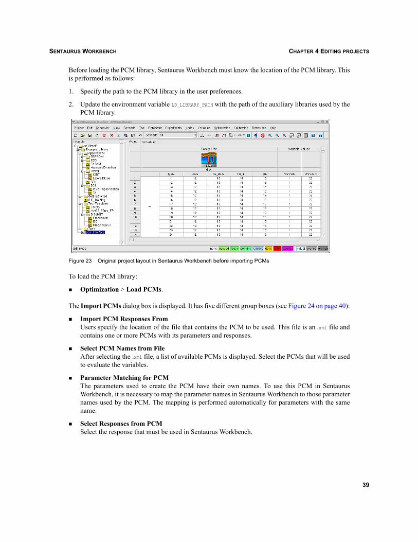
SENTAURUS WORKBENCH CHAPTER 4 EDITING PROJECTS
Before loading the PCM library, Sentaurus Workbench must know the location of the PCM library. Thisis performed as follows:
1. Specify the path to the PCM library in the user preferences.
2. Update the environment variable LD_LIBRARY_PATH with the path of the auxiliary libraries used by thePCM library.
Figure 23 Original project layout in Sentaurus Workbench before importing PCMs
To load the PCM library:
Optimization > Load PCMs.
The Import PCMs dialog box is displayed. It has five different group boxes (see Figure 24 on page 40):
Import PCM Responses FromUsers specify the location of the file that contains the PCM to be used. This file is an .xml file andcontains one or more PCMs with its parameters and responses.
Select PCM Names from FileAfter selecting the .xml file, a list of available PCMs is displayed. Select the PCMs that will be usedto evaluate the variables.
Parameter Matching for PCMThe parameters used to create the PCM have their own names. To use this PCM in SentaurusWorkbench, it is necessary to map the parameter names in Sentaurus Workbench to those parameternames used by the PCM. The mapping is performed automatically for parameters with the samename.
Select Responses from PCMSelect the response that must be used in Sentaurus Workbench.
39

SENTAURUS WORKBENCHCHAPTER 4 EDITING PROJECTS
User-Defined Response NamesThe default naming scheme of the PCM responses in Sentaurus Workbench is %<RESPONSE>_NR. Theuser can modify the default response name (<RESPONSE>_NR) as required, but the percent symbol (%)must always precede the response name.
Figure 24 Import PCMs dialog box
After clicking OK, the PCM library is imported and evaluates the selected PCM according to themapped parameters. The results are displayed in the Family Tree view.
Figure 25 Family Tree view showing results of PCM evaluation
40

SENTAURUS WORKBENCH CHAPTER 4 EDITING PROJECTS
NodesA node is a point in the Family Tree where (possibly virtual) parametric splits can occur or where asimulation tool can be changed in the tool flow. Nonvirtual nodes have simulation results. In one sense,a node is an ‘atom’ of the simulation.
Viewing and editing properties of nodesIn a new project, to add the first tool to the flow:
1. Select a node in the simulation flow.
2. Nodes > Properties.A dialog box is displayed as shown in Figure 26.
3. Change the value of the node in the Value box.
4. Change the status of the node in the Status list.
5. Click OK.
Figure 26 Node information dialog box
41

SENTAURUS WORKBENCHCHAPTER 4 EDITING PROJECTS
Experiments and scenariosAn experiment or parameter setting is a tuple that contains one value for each parameter of the flow. Ascenario is a subtree of a simulation tree of Sentaurus Workbench that contains a particular subset ofexperiments. Scenarios can overlap, that is, a particular node or path can be part of more than onescenario. Scenarios can be run and edited independently.
NOTE All projects have a scenario ‘all’ that includes all the scenarios of a project.
Adding experimentsAn experiment can be added only if parameters are defined in a flow.
To add a single experiment:
1. Experiments > Add New Experiment.
2. Choose a scenario where the new experiment is to be added (the current scenario is preset).
3. Select or type values for all parameters.If an experiment is selected, the values are preset to those of the selected experiment.
4. Click Apply to add more experiments or click OK to add the experiment and close the dialog box.
Figure 27 Add New Experiment dialog box
To add experiments by adding parameter values:
1. Experiments > Add Values.
2. Choose a scenario where the new experiment is to be added (the current scenario is preset).
3. Select a parameter for which you want to add a value.
4. Select a minimum value for the parameter. It can be alphanumeric if only one value is added; it must be numeric if more than one value isadded.
42
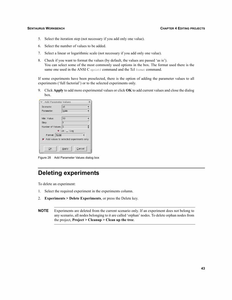
SENTAURUS WORKBENCH CHAPTER 4 EDITING PROJECTS
5. Select the iteration step (not necessary if you add only one value).
6. Select the number of values to be added.
7. Select a linear or logarithmic scale (not necessary if you add only one value).
8. Check if you want to format the values (by default, the values are passed ‘as is’).You can select some of the most commonly used options in the box. The format used there is thesame one used in the ANSI C sprintf command and the Tcl format command.
If some experiments have been preselected, there is the option of adding the parameter values to allexperiments (‘full factorial’) or to the selected experiments only.
9. Click Apply to add more experimental values or click OK to add current values and close the dialogbox.
Figure 28 Add Parameter Values dialog box
Deleting experimentsTo delete an experiment:
1. Select the required experiment in the experiments column.
2. Experiments > Delete Experiments, or press the Delete key.
NOTE Experiments are deleted from the current scenario only. If an experiment does not belong toany scenario, all nodes belonging to it are called ‘orphan’ nodes. To delete orphan nodes fromthe project, Project > Cleanup > Clean up the tree.
43

SENTAURUS WORKBENCHCHAPTER 4 EDITING PROJECTS
Sorting experimentsSentaurus Workbench can sort experiments according to the values of a selected parameter.
To sort experiments:
1. Select experiments.
2. Experiments > Sort Experiments.The Select Parameters to Sort dialog box is displayed.
3. Select the scenario, parameter, and sorting order as required.
4. Click OK.
Figure 29 Select Parameters to Sort dialog box
Importing experiments from a fileTo import experiments from a text file that contains character-separated values, for example, a .csv file:
1. Experiments > Import From a File.
2. Select the required file.
3. Select or type a scenario where the experiment is to be imported.
4. For each parameter or variable, select either a column number in the file from which you want totake this parameter values (the column number starts from 0) or a constant value that will be usedfor all imported experiments.
5. Select a delimiter between columns in the file.
6. Select the number of first lines that will be skipped when reading experiments.
7. Select how many experiments (lines) are read from the file.This number is preset to the number of lines in the file.
8. Select whether consecutive delimiters are to be treated as one.This option is often used for space-separated values.
9. Click Preview to view which experiments will be imported.
10. Click OK.
44

SENTAURUS WORKBENCH CHAPTER 4 EDITING PROJECTS
Figure 30 Import Experiments dialog box
Viewing experiment propertiesTo view experiment properties:
1. Select the required experiment in the experiments column.
2. Experiments > Properties or double-click the experiment.
45

SENTAURUS WORKBENCHCHAPTER 4 EDITING PROJECTS
Adding scenariosTo add a scenario to the simulation tree:
1. Scenario > Add.
2. Type a new scenario name.
3. Click OK.
Deleting scenariosTo delete a scenario from the simulation tree:
1. Scenario > Delete.
2. Select the required scenario.To select multiple scenarios, press the Ctrl key during selection.
3. Click OK.
Copying and moving experiments between scenariosTo copy or move experiments between scenarios:
1. Select the experiments to be copied in the experiment column.To select multiple experiments, press the Ctrl key during selection.
2. Edit > Copy to copy experiments or Edit > Cut to move experiments.
3. Select the scenario where you want to copy experiments from the scenario box in the toolbar, or Scenario > Next, or Scenario > Previous.
4. Edit > Paste.
Copying and moving experiments between projectsTo copy and move experiments between projects if both projects have same number of parameters in theflow:
1. Select the experiments to be copied in the experiments column.To select multiple experiments, press the Ctrl key during selection.
2. Edit > Copy to copy experiments or Edit > Cut to move experiments.
3. Open a project where you want to copy experiments in the same instance of Sentaurus Workbench.
46
SENTAURUS WORKBENCH CHAPTER 4 EDITING PROJECTS
4. Select the scenario where you want to copy experiments from the scenario box in the toolbar, or Scenario > Next, or Scenario > Previous.
5. Edit > Paste.
Pruning and unpruningPruning is a useful operation to remove superfluous paths from a tree. An entire subtree can be removed,reducing the simulation tree. Pruning and unpruning is not as important as in previous versions ofSentaurus Workbench, since it is no longer necessary to use a full factorial tree. The feature is here forbackward compatibility and special applications that require partial trees.
To prune or unprune a tree:
1. Select the required nodes. The whole subtree starting with these nodes will be pruned (or unpruned).
2. Nodes > Prune or Nodes > Unprune.
Pruned and orphaned nodes can be hidden from view. To hide or show nodes:
View > Show Pruned or F8.
Locking nodesNode locking is useful for large projects where preprocessing all nodes is cumbersome. In addition, ifusers need to keep the current status of the preprocessing results for a specific tool, scenario, or node,the corresponding nodes can be locked. Locking the nodes prevents the nodes from being preprocessed.These nodes can be unlocked if preprocessing is required.
To lock or unlock nodes:
1. Select the required nodes.
2. Nodes > Lock or Nodes > UnLock.
47

SENTAURUS WORKBENCHCHAPTER 4 EDITING PROJECTS
Quick-running nodesThe quick-running of nodes submits the nodes directly to the queue specified and the nodes are run basedon the function of the queue. The project is set to a running state.
To quick-run a node:
1. Select the nodes.
2. Nodes > Quick Run and select the required queue.
NOTE The queue list is loaded from the global queue definition file.
48
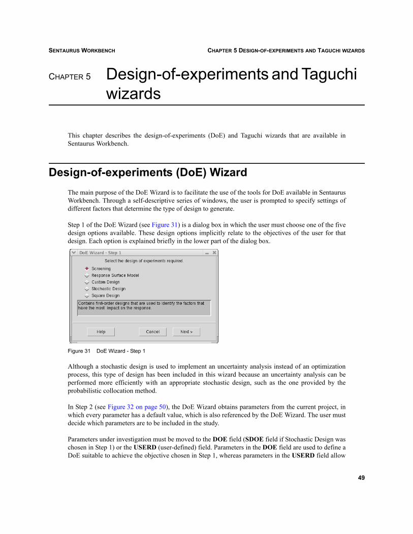
SENTAURUS WORKBENCH CHAPTER 5 DESIGN-OF-EXPERIMENTS AND TAGUCHI WIZARDS
Sentaurus Workbench
CHAPTER 5 Design-of-experiments and Taguchi wizards
This chapter describes the design-of-experiments (DoE) and Taguchi wizards that are available inSentaurus Workbench.
Design-of-experiments (DoE) WizardThe main purpose of the DoE Wizard is to facilitate the use of the tools for DoE available in SentaurusWorkbench. Through a self-descriptive series of windows, the user is prompted to specify settings ofdifferent factors that determine the type of design to generate.
Step 1 of the DoE Wizard (see Figure 31) is a dialog box in which the user must choose one of the fivedesign options available. These design options implicitly relate to the objectives of the user for thatdesign. Each option is explained briefly in the lower part of the dialog box.
Figure 31 DoE Wizard - Step 1
Although a stochastic design is used to implement an uncertainty analysis instead of an optimizationprocess, this type of design has been included in this wizard because an uncertainty analysis can beperformed more efficiently with an appropriate stochastic design, such as the one provided by theprobabilistic collocation method.
In Step 2 (see Figure 32 on page 50), the DoE Wizard obtains parameters from the current project, inwhich every parameter has a default value, which is also referenced by the DoE Wizard. The user mustdecide which parameters are to be included in the study.
Parameters under investigation must be moved to the DOE field (SDOE field if Stochastic Design waschosen in Step 1) or the USERD (user-defined) field. Parameters in the DOE field are used to define aDoE suitable to achieve the objective chosen in Step 1, whereas parameters in the USERD field allow
49

SENTAURUS WORKBENCHCHAPTER 5 DESIGN-OF-EXPERIMENTS AND TAGUCHI WIZARDS
for the abovementioned DoE to be run under different conditions, each parameter measuring a differentresponse.
Figure 32 DoE Wizard - Step 2
Unselected parameters remain in the left pane and are considered as constants during the simulation.Their values are the default ones assigned by the user in the creation of the project.
The SDOE field becomes active only when the Stochastic Design option has been selected in Step 1,that is, only if the goal is to perform an uncertainty analysis. Therefore, it is not possible to mix, in thesame experimental plan, parameters that by definition have different objectives, such as deterministicparameters that are used to optimize the response and stochastic parameters intended to perform anuncertainty analysis.
Step 2 is the same for every option chosen in Step 1, but the following steps are different depending onthe objective defined in Step 1.
Figure 33 DoE Wizard - Step 3
50

SENTAURUS WORKBENCH CHAPTER 5 DESIGN-OF-EXPERIMENTS AND TAGUCHI WIZARDS
ScreeningFor a screening process, Step 3 corresponds to a dialog box such as the one in Figure 33 on page 50.Here, the user must specify the levels for each parameter and the scale in which they are measured.
When the parameters are defined, the DoE Wizard provides, in a fourth step, a list of the suitable designsto fit a first-order model. The length of the list depends on the number of parameters selected in the DOEfield (Step 2). Step 4 (shown in Figure 34) has a column that displays the required number of runs tocomplete each design and a column that shows the resolution of each design.
The user must choose one of the designs. Consider that the higher the resolution, the better the qualityof the fitted model will be and the higher the cost of the experimental plan will be.
Figure 34 DoE Wizard - Step 4 for screening
Response surface modelStep 3 for a response surface model (RSM) is the same as for screening (see Figure 34), nevertheless,the user must be aware that, this time, the objective is to fit a second-order model. This implies that theDoE Wizard adds automatically at least one more level to each parameter.
Step 4 for a RSM (see Figure 37 on page 53) provides a list of designs that allow the fitting of a second-order model. The second column in the table shows the number of simulations or runs required tocomplete each experimental plan.
If Central Composite Complete or Central Composite Small is chosen, the user must define the axialdistance. To do so, there is a special step (see Figure 35 on page 52).
51

SENTAURUS WORKBENCHCHAPTER 5 DESIGN-OF-EXPERIMENTS AND TAGUCHI WIZARDS
Figure 35 DoE Wizard - Step 5 for response surface model
Stochastic designStep 3 for stochastic design (see Figure 36) allows for the definition of characteristics for the stochasticparameters. This means that the user must associate each parameter with a probabilistic distribution anda number of collocation points (parameter settings).
Figure 36 DoE Wizard - Step 3 for stochastic design
52

SENTAURUS WORKBENCH CHAPTER 5 DESIGN-OF-EXPERIMENTS AND TAGUCHI WIZARDS
Square designSquare designs are deterministic designs that are used to study more than two levels for each parameterin an economical way, using Latin or Greco Latin or Hyper Greco Latin square. In this case, Step 3 (seeFigure 37) allows for the definition of three up to eight levels for each parameter.
Figure 37 DoE Wizard - Step 3 for square design
User-defined parametersUntil now, only DoE and SDoE parameters have been explained, but user-defined parameters can bedefined in the same way, despite the option selected in Step 1. These parameters can be defined as eithercontinuous with any number of levels or categorical.
Figure 38 DoE Wizard - Step 3 for user-defined parameters
53
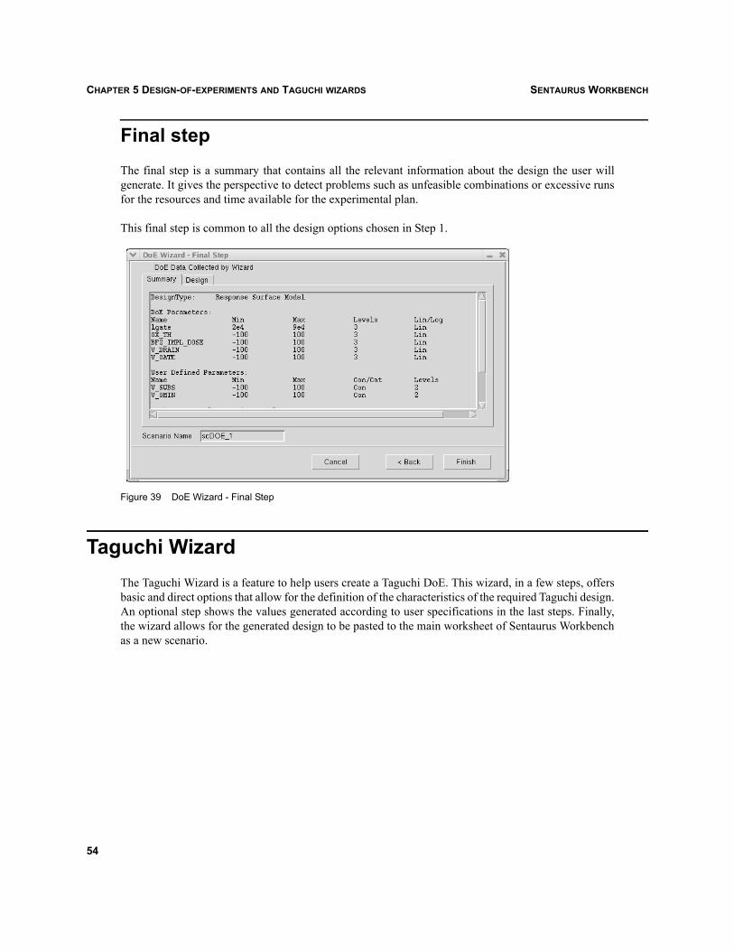
SENTAURUS WORKBENCHCHAPTER 5 DESIGN-OF-EXPERIMENTS AND TAGUCHI WIZARDS
Final stepThe final step is a summary that contains all the relevant information about the design the user willgenerate. It gives the perspective to detect problems such as unfeasible combinations or excessive runsfor the resources and time available for the experimental plan.
This final step is common to all the design options chosen in Step 1.
Figure 39 DoE Wizard - Final Step
Taguchi WizardThe Taguchi Wizard is a feature to help users create a Taguchi DoE. This wizard, in a few steps, offersbasic and direct options that allow for the definition of the characteristics of the required Taguchi design.An optional step shows the values generated according to user specifications in the last steps. Finally,the wizard allows for the generated design to be pasted to the main worksheet of Sentaurus Workbenchas a new scenario.
54

SENTAURUS WORKBENCH CHAPTER 5 DESIGN-OF-EXPERIMENTS AND TAGUCHI WIZARDS
In the first step (see Figure 40), the number level of the Taguchi design is selected.
Figure 40 Taguchi Wizard - Select Design
Note that:
Choices are divided between two group boxes: 2 Level and Multilevel with noise.
When a Multilevel with noise design is selected, the Select Outer Array Design options areavailable to allow the user to define the design to be used as noise.
In the next steps:
The Factors column is a non-editable header column, containing the experiment referencesdesignated alphabetically, A, B, C, and so on.
The Parameters column allows for the selection of one of the valid parameters from SentaurusWorkbench. When a parameter is selected, it is not available for any further selection on the otherboxes.
In the second step of 2 Level models (see Figure 41 on page 56), users define the design correspondingto the Taguchi inner array. The columns Center and Shift must be set to define parameter values ascenter shift. ±
55
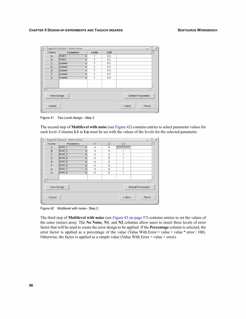
SENTAURUS WORKBENCHCHAPTER 5 DESIGN-OF-EXPERIMENTS AND TAGUCHI WIZARDS
Figure 41 Two Level design - Step 2
The second step of Multilevel with noise (see Figure 42) contains entries to select parameter values foreach level. Columns L1 to Ln must be set with the values of the levels for the selected parameter.
Figure 42 Multilevel with noise - Step 2
The third step of Multilevel with noise (see Figure 43 on page 57) contains entries to set the values ofthe outer (noise) array. The No Noise, N1, and N2 columns allow users to insert three levels of errorfactor that will be used to create the error design to be applied. If the Percentage column is selected, theerror factor is applied as a percentage of the value (Value With Error = value + value * error / 100).Otherwise, the factor is applied as a simple value (Value With Error = value + error).
56

SENTAURUS WORKBENCH CHAPTER 5 DESIGN-OF-EXPERIMENTS AND TAGUCHI WIZARDS
Figure 43 Multilevel with noise - Step 3
By clicking View Design (see Figure 43) in the last step of the wizard, the optional View Design dialogbox is displayed (see Figure 44), where the user can see the design that will be generated.
Figure 44 Taguchi Wizard - View Design dialog box
57

SENTAURUS WORKBENCHCHAPTER 5 DESIGN-OF-EXPERIMENTS AND TAGUCHI WIZARDS
After clicking Finish, the selected design is created in the main view (see Figure 45).
Figure 45 Taguchi Wizard results
58

SENTAURUS WORKBENCH CHAPTER 6 PREPROCESSING PROJECTS
Sentaurus Workbench
CHAPTER 6 Preprocessing projects
As previously mentioned in Parameters on page 32, one of the most important features of SentaurusWorkbench is the support for project parameterization. A parameterized project consists of a set ofexperiments where certain sensible input variables take different values. A parameterized project isrepresented as a tree structure called gtree.
In a project, the user provides the set of input file templates for each tool as defined in the tool database.The user can express variations in templates using the preprocessor language of Sentaurus Workbench.There are two categories of preprocessor language constructs: preprocessor #-commands (seePreprocessor #-commands on page 60) and @-references (see @-references and tree navigation onpage 61). The Sentaurus Workbench preprocessor supports also special Tcl command blocks, whichcontain arbitrary Tcl commands (see Tcl command blocks on page 66).
To differentiate the nodes in gtree and to take into account already computed results, spp – the SentaurusWorkbench preprocessor – automatically generates actual input files at run-time. Dynamicpreprocessing enables a simulation to be dependent on the results of other simulations, that is, thebehavior of a node can vary as a function of variables extracted at other nodes.
Global and run-time preprocessingPreprocessing is performed in two phases:
1. A global, projectwide preprocessing phase, before project execution. This phase does not create realinput files (pp*). Instead, it scans the user input templates of the tool to extract the jobinterdependencies and produce the project execution graph (file gexec.cmd), and to find the #setcommands and insert variable values into the project variable file (gvars.dat). In addition, globalpreprocessing can be used on expressions, nodes, and scenarios (see Node expressions on page 62).
2. Generation of job input files before a job is started. All preprocessor commands and @-referencesare resolved and replaced at that time. A variable reference is replaced with the most recentlyextracted value or with the value given at the closest #set command if there is no extracted value.Finally, all preprocessor Tcl blocks are extracted, evaluated, and substituted with the result of theTcl evaluation (standard output).
To perform phase 1 only, use the command:
gpp PROJECT
To perform both phases for the whole project (create the execution graph and variable file, and generateall pp* input files), use the command:
gpp -input PROJECT
59
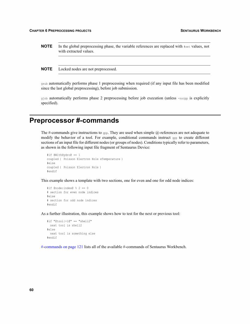
SENTAURUS WORKBENCHCHAPTER 6 PREPROCESSING PROJECTS
NOTE In the global preprocessing phase, the variable references are replaced with #set values, notwith extracted values.
NOTE Locked nodes are not preprocessed.
gsub automatically performs phase 1 preprocessing when required (if any input file has been modifiedsince the last global preprocessing), before job submission.
gjob automatically performs phase 2 preprocessing before job execution (unless -nocpp is explicitlyspecified).
Preprocessor #-commandsThe #-commands give instructions to gpp. They are used when simple @-references are not adequate tomodify the behavior of a tool. For example, conditional commands instruct gpp to create differentsections of an input file for different nodes (or groups of nodes). Conditions typically refer to parameters,as shown in the following input file fragment of Sentaurus Device:
#if @WithHydro@ == 1coupled { Poisson Electron Hole eTemperature }#elsecoupled { Poisson Electron Hole }#endif
This example shows a template with two sections, one for even and one for odd node indices:
#if @node:index@ % 2 == 0# section for even node indices#else# section for odd node indices#endif
As a further illustration, this example shows how to test for the next or previous tool:
#if "@tool|+1@" == "shell2" next tool is shell2#else next tool is something else#endif
#-commands on page 121 lists all of the available #-commands of Sentaurus Workbench.
60

SENTAURUS WORKBENCH CHAPTER 6 PREPROCESSING PROJECTS
@-references and tree navigationSince Sentaurus Workbench must control all tool input and output files in the simulation tree anddetermine job interdependencies, file names should only appear as file references in input files. Do notuse absolute, hard-coded file names. Use node references instead of hard-coded node keys. At run-time,gpp substitutes file references and node references with the corresponding file names or node keys.
The following conventions and notations are used. Each node is uniquely identified by its key noted nkey.Node keys can be displayed in the Project Editor. Tool output file names are prefixed withn<nkey>_<acronym>, where <acronym> is a three-character string identifying a specific tool. The set of nodesat a certain tree level represents all occurrences of the tool at that level. These nodes are indexed from 1to n, where 1 denotes the leftmost and n the rightmost node. A node index is the absolute position of thenode in its tree level.
A simple reference of Sentaurus Workbench usually refers to the current node. Navigation operators canbe used to move the reference from the current node to another node in the tree. Relative navigation canbe in all directions around the current node: up, down, left, right, and also in absolute indices.
To illustrate the use of file references, a typical Sentaurus Device File section is:
File {grid = "@grid@"doping = "@doping@”plot = "@dat@"current = "@plot@"output = "@log@"
}
NOTE For historical reasons, the meaning of the keyword plot is different in Sentaurus Device andSentaurus Workbench. In Sentaurus Device, plot refers to the plots of primary and derivedquantities over the computational domain. In Sentaurus Workbench, plot refers to I–V curves.
NOTE It is necessary to differentiate between @-references and @-character expressions:@-references can be parameters, expressions, or commands that are enclosed by a pair of @.The enclosed content is evaluated and substituted by the preprocessor.@-character expressions are not substituted by the preprocessor. They are treated verbatimbecause they have a special meaning for their target tools. A character expression is definedby @<string><blank>.
61
SENTAURUS WORKBENCHCHAPTER 6 PREPROCESSING PROJECTS
Node filtersA node filter is a Tcl expression that evaluates to true (!=0) or false (0) for any existing node in thesimulation tree. The syntax of a filter is:
filter: "{" EXPR "}"
where EXPR is a Tcl expression that evaluates to a number. EXPR can refer to parameters or variablesexisting in the current tree using the $NAME notation, for example, the expression:
{ $P2 == 3 && $V1 > 2 }
will evaluate to true for nodes where the value of parameter P2 is equal to 3 and the value of variable V1is greater than 2.
Nodes for which a referenced parameter or variable is not defined are rejected (evaluated to false). Inother words, the previous expression is equivalent to:
{ ([info exists P2] && $P2 == 3) && ([info exists V1] && $V1 > 2) }
Additionally, EXPR recognizes the two predefined functions min(NAME) and max(NAME). For example:
{ $P2 == min(P2) }
will evaluate to true for nodes where the value of parameter P2 is equal to the minimal value of P2.
Node expressionsSentaurus Workbench provides expressions – abbreviated gexpr – to select nodes in the simulation tree.A gexpr returns a list of node keys and is especially used in the Scheduler to submit nodes for execution.The syntax of a gexpr is detailed in Node expressions on page 124. For example:
"sc1|last:{$P1 == 1} * sc2|last:{$P1 == 1}"
will return the leaf nodes belonging to both scenarios sc1 and sc2, where parameter P1 is equal to 1.
Split pointsA parameter introduces a new level in the simulation tree to the right of the tool step. Viewed from thetree, a parameter splits the overall tool simulation phase into two subphases. This is only an abstract viewbecause each tool instance usually executes the entire simulation phase from the beginning to end in onerun.
As a result, the same first subphase(s) is unnecessarily executed several times. This is only true for toolswhose command file defines a linear control flow (that is, a flow executed sequentially from the
62

SENTAURUS WORKBENCH CHAPTER 6 PREPROCESSING PROJECTS
beginning to end, command after command). These tools are called linear tools. Typically, processsimulation tools are linear tools.
Sentaurus Workbench provides a splitting facility so that linear tools can save and restore their state;each intermediate branch in the tree can be executed only once. This facility can save considerablecomputing time, especially for lengthy jobs with multiple phases.
A tool can only be split when the Save and Load commands are defined in the tool database. For example,Dios has the following two lines in the standard tool database:
set WB_tool(dios,split,save_cmd) "Save(File='n@node@', type=dmp.gz)"set WB_tool(dios,split,load_cmd) "Load(File='n@previous@')"
NOTE To ensure that Sentaurus Workbench shows the real status of the intermediate nodes, checkwhether the option View > Tree Options > Check Virtual Nodes is selected (see Real andvirtual family nodes on page 19).
Preprocessed variablesLike a parameter, a variable holds a value and can be referenced in any form of @-references. The maindifference is that a variable does not create a split in the simulation flow and, therefore, does not changethe shape of the simulation tree.
The #set command is used to define a preprocessed variable and assign a value to it:
#set <varname> <value>
A defined variable can then be referenced by its name in any @-reference notation. A variable referencecreates an execution dependency from the node where the reference is performed to the first ancestorwhere the variable has been set. The scope of a variable is similar to that of a parameter, that is, from thenode with the first #set directive to all of its descendants.
A variable can be reassigned in two ways:
By another #set directive, that is, by overriding it with another preprocessed value.
Through an extraction, that is, by overriding it with an extracted value (see Extracted variables onpage 64).
All variables are shown in the Family Tree.
A typical use of #set commands is to define a set of variables bound to a parameter, such as the fields ofa record:
#if @PARAM@ == 1#set PARAM_V1 1.5#set PARAM_V2 2.5#elif @PARAM@ == 2
63

SENTAURUS WORKBENCHCHAPTER 6 PREPROCESSING PROJECTS
#set PARAM_V1 11.5#set PARAM_V2 12.5#endif
This construct avoids the declaration of two artificial parameters and reduces the size of the overallproject tree.
Extracted variablesAnother common use of variables is to extract a value from the tool output file and refer to it in the nexttool input file.
Values are extracted from node output files. After the node has been successfully executed, its outputfile is parsed for strings that match the following mask:
DOE: <varname> <value>
Then, the values found are written to the gvars.dat file. If the specified variable already exists, theextracted value will overwrite the existing one. If the specified variable does not exist, that is, it was notdefined globally or with the #set command, a new variable will be created. After that, the extractedvariable can be referenced in any subsequent tool input files by using standard preprocessor@-references.
The only way to inform Sentaurus Workbench that a value must be extracted during the simulation andassigned to some variable is to provide the DOE: <varname> <value> string in the node output file. Usually,it should be printed in the tool command file. The corresponding command strictly depends on the tooland its command syntax. For example, for Sentaurus Process, it can be a simple Tcl command:
puts "DOE: ENERGY 120.56"
Inspect supports another way of exporting of values to the Family Tree. It is possible to use the ft_scalarfunction in the Inspect command file:
ft_scalar <varname> <value>
This function assigns the value to the specified variable of Sentaurus Workbench. If the variable doesnot exist, it will be created. In this way, nothing is sent to the node output file: the exported value goesdirectly to the variable definition.
Extracted values and preprocessed values are separated from each other. Extracted values becomeavailable during the simulation running phase, while preprocessed values are already known at thepreprocessing stage.
64
SENTAURUS WORKBENCH CHAPTER 6 PREPROCESSING PROJECTS
The following example demonstrates how the algorithm extracts values from the simulation step andaccesses them in the subsequent simulation steps:
1. In the tool where the extraction is performed, an arbitrary default value must be assigned to theextracted variable:
#set EXTRACTED_VAR 0
This command could be also specified in any preceding tools if any.
2. In the tool where the extraction is performed, the printing command must be specified in the toolcommand file. In the case of Sentaurus Process, it could be:
puts "DOE: ENERGY 120.56"
or:
puts "DOE: ENERGY @ENERGY_2@"
where ENERGY_2 is another variable.
3. The variable EXTRACTED_VAR can be referenced in any subsequent tool input files by using standardpreprocessor @-references and #-commands, such as:
@EXTRACTED_VAR@@< @EXTRACTED_VAR:+1@ / 2 >@#if @EXTRACTED_VAR@ > 1.5e15...#endif
NOTE A common cause of errors when using extracted variables is that a corresponding variabledoes not exist during preprocessing. In this case, preprocessing of the project can fail if thereare any references to this variable in the input files of other tools. To avoid this error, globallydeclare the variable or use the #set preprocessing command.
NOTE Extracted variables work only for tools for which the extracting algorithm has been definedin the tool database. For example, the global tool database defines it for Sentaurus Process inthis way: set WB_tool(sprocess,epilogue) { extract_vars $wdir @stdout@ @node@; ... }
where the extract_vars function is defined also in the global tool database. This definitionmeans that the values for each executed node will be extracted from the output file on thebasis of the DoE: the pattern specified in the function. In the global tool database, thisextraction algorithm is defined for Sentaurus Process, Dios, TSUPREM-4, Taurus Process,Taurus Device, Medici, Davinci, Aurora, Raphael, Inspect, and Measure. To enable othertools to support extracted variables, the corresponding definition must be specified in the useror project tool database. It is also possible to define a user-specific extracting algorithm forextracting values between Family Tree steps.
65

SENTAURUS WORKBENCHCHAPTER 6 PREPROCESSING PROJECTS
Execution dependenciesDuring preprocessing, all dependencies in the files are analyzed in the following way:
If there is a file reference @file_type@ with possible, additional, relative direction suffixes (seePreprocessor and reference syntax on page 119 for information about @-references and tree navigation)in any of the command files or parameterized input files, the execution is made dependent on thesuccessful completion of the pointed node.
NOTE @node@ references do not create any dependencies and there are no implicit child to parentdependencies.
Dependencies can be forced using the #setdep directive. For example, #setdep @node|-1:all@ creates abarrier before the current level, that is, no node at the current level can start execution before all nodesat the previous level have been successfully completed. gpp checks for circular references and fails if oneis found.
Dependencies can be explicitly removed using the #remdep command, for example:
#remdep @node|+1@
NOTE The order in which dependencies are set or unset is important. Unsetting a dependency doesnot have any effect if the dependency is set again later in the same input file, either implicitlyor explicitly. Therefore, a #remdep directive at the beginning of the file does not have anyeffect; this directive typically appears at the end of an input file.
NOTE Although the reference @previous@ is, in principle, equivalent to @node|-1@, the difference isthat @previous@ creates a dependency, while @node|-1@ does not.
Tcl command blocks
Creating Tcl command blocksThe concept of Tcl command blocks is to bring additional power to inflexible and hard-to-use languagefor some tools incorporated into Sentaurus Workbench. Tcl command blocks consist of an arbitrary setof Tcl command lines that are delimited by "!(" and ")!". During the final stage of preprocessing, Tclcommand blocks are extracted and evaluated by the preprocessor. In the node input file, each Tcl blockis replaced with the standard output of its Tcl evaluation.
66

SENTAURUS WORKBENCH CHAPTER 6 PREPROCESSING PROJECTS
The following example illustrates the use of Tcl command blocks to power some Sentaurus Device code.Consider the following part of an input file for Sentaurus Device (Tcl blocks are italicized):
#if @<polarization>@ == "on"!(#=============================================================# Computation of piezo/spontaneous charge# using new SWB capability to interpret Tcl command blocks# SWB version 2006.06#=============================================================set q 1.602e-19;# elementary chargeset Psp_AlN [expr -8.1e-6/$q];# AlN build-in spontaneous polarizationset Psp_GaN [expr -2.9e-6/$q];# GaN build-in spontaneous polarizationset Psp_AlGaN [expr @x@*$Psp_AlN+(1-@x@)*$Psp_GaN]; # AlGaN spontaneous polarizationset DPsp [expr $Psp_GaN-$Psp_AlGaN]; # interface charge due to spontaneous polarizationset e33i [expr (@x@*1.46e-4+(1-@x@)*0.73e-4)/$q]set e31i [expr (@x@*-0.60e-4+(1-@x@)*-0.49e-4)/$q]set c13i [expr @x@*108+(1-@x@)*103]set c33i [expr @x@*373+(1-@x@)*405]set straini [expr @x@*(3.189-3.112)/(@x@*3.112+(1-@x@)*3.189)]set Ppz_AlGaN [expr 2*$straini*($e31i-$c13i/$c33i*$e33i)]set DPpz $Ppz_AlGaNset intCharge [expr $DPsp+$DPpz]; # resulting value of the interface charge# Transfer the resulting charge to the project Family Tree as SWB variableset SWB_VARIABLES(Charge) [format %.6e $intCharge])!* Spontaneous polarization for AlGaN: !(puts -nonewline [format %.2e $Psp_AlGaN])!* Piezopolarization for AlGaN: !(puts -nonewline [format %.2e $Ppz_AlGaN])!* Total AlGaN Polarization: !(puts [format %.2e [expr $Psp_AlGaN+$Ppz_AlGaN]])!* Total GaN Polarization: !(puts [format %.2e $Psp_GaN])!#endif...Physics(materialinterface="GaN/AlGaN"){#if @<polarization>@ == "on"
Charge( Conc=!(puts -nonewline [format %.4e $intCharge])! )#endif#if [string match "*NL*" "@model@"]* hetero barrier non-local barrier tunnelingRecombination(eBarrierTunneling(nonlocal))
#endif}...
This file is preprocessed to the following node file:
* Spontaneous polarization for AlGaN: -5.06e+13* Piezopolarization for AlGaN: -1.85e+13* Total AlGaN Polarization: -6.91e+13* Total GaN Polarization: -1.81e+13...Physics(materialinterface="GaN/AlGaN"){
Charge( Conc=1.3925e+13 )
67
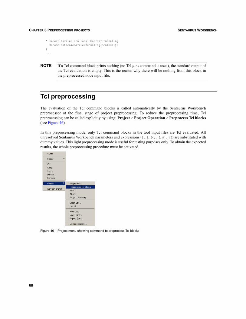
SENTAURUS WORKBENCHCHAPTER 6 PREPROCESSING PROJECTS
* hetero barrier non-local barrier tunnelingRecombination(eBarrierTunneling(nonlocal))
}...
NOTE If a Tcl command block prints nothing (no Tcl puts command is used), the standard output ofthe Tcl evaluation is empty. This is the reason why there will be nothing from this block inthe preprocessed node input file.
Tcl preprocessingThe evaluation of the Tcl command blocks is called automatically by the Sentaurus Workbenchpreprocessor at the final stage of project preprocessing. To reduce the preprocessing time, Tclpreprocessing can be called explicitly by using: Project > Project Operation > Preprocess Tcl blocks(see Figure 46).
In this preprocessing mode, only Tcl command blocks in the tool input files are Tcl evaluated. Allunresolved Sentaurus Workbench parameters and expressions (@..@, @<..>@, @[..]@) are substituted withdummy values. This light preprocessing mode is useful for testing purposes only. To obtain the expectedresults, the whole preprocessing procedure must be activated.
Figure 46 Project menu showing command to preprocess Tcl blocks
68
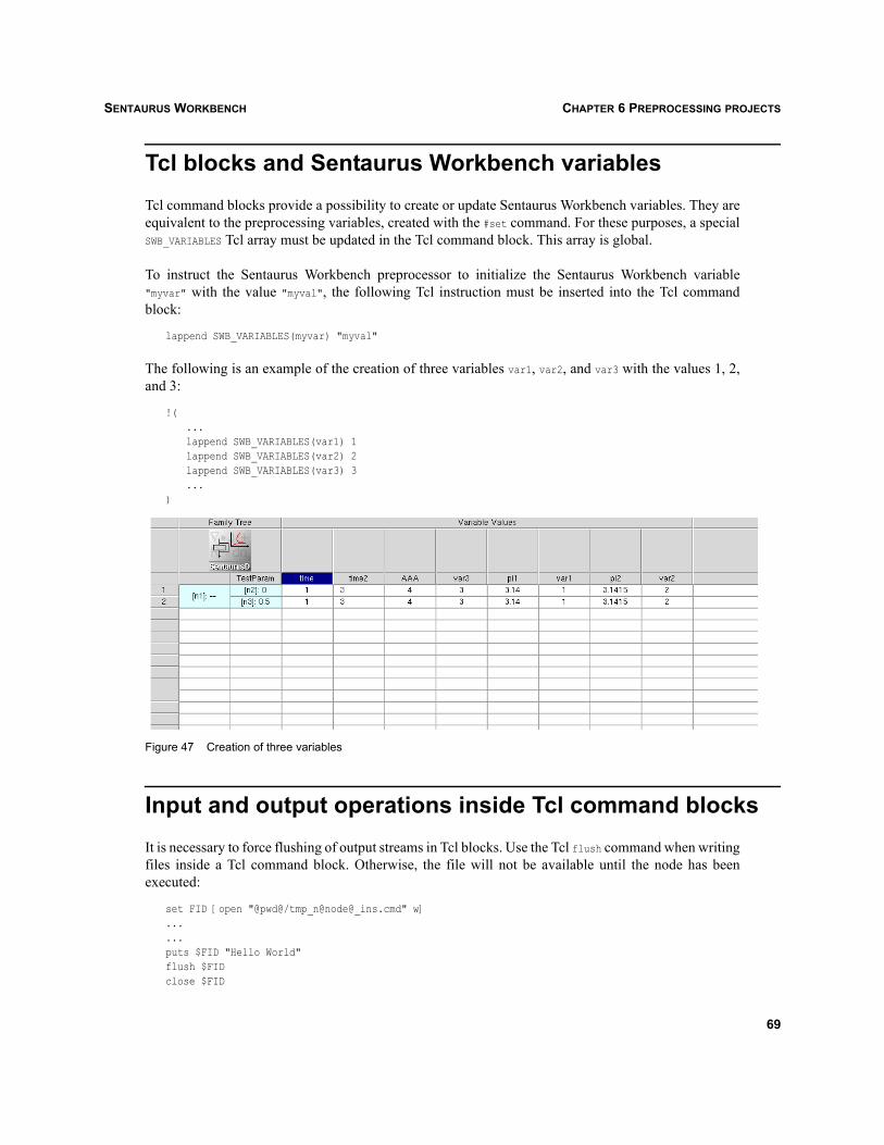
SENTAURUS WORKBENCH CHAPTER 6 PREPROCESSING PROJECTS
Tcl blocks and Sentaurus Workbench variablesTcl command blocks provide a possibility to create or update Sentaurus Workbench variables. They areequivalent to the preprocessing variables, created with the #set command. For these purposes, a specialSWB_VARIABLES Tcl array must be updated in the Tcl command block. This array is global.
To instruct the Sentaurus Workbench preprocessor to initialize the Sentaurus Workbench variable"myvar" with the value "myval", the following Tcl instruction must be inserted into the Tcl commandblock:
lappend SWB_VARIABLES(myvar) "myval"
The following is an example of the creation of three variables var1, var2, and var3 with the values 1, 2,and 3:
!(...lappend SWB_VARIABLES(var1) 1lappend SWB_VARIABLES(var2) 2lappend SWB_VARIABLES(var3) 3...
)
Figure 47 Creation of three variables
Input and output operations inside Tcl command blocksIt is necessary to force flushing of output streams in Tcl blocks. Use the Tcl flush command when writingfiles inside a Tcl command block. Otherwise, the file will not be available until the node has beenexecuted:
set FID [open "@pwd@/tmp_n@node@_ins.cmd" w]......puts $FID "Hello World"flush $FIDclose $FID
69

SENTAURUS WORKBENCHCHAPTER 6 PREPROCESSING PROJECTS
Summary of rules for using Tcl command blocksWhen using Tcl command blocks, note the following requirements:
A Tcl block contains an arbitrary number of native Tcl instructions between a "!(" and ")!" pair ofsymbols.
Tcl blocks cannot be nested.
A Tcl block can be inserted in any place of any preprocessed file (tool command files, parameterfiles for Sentaurus Device, and so on).
Each file can contain an arbitrary number of Tcl blocks.
All Tcl blocks are evaluated by a separate Tcl interpreter, which is specific for each experiment inthe project.
All Tcl blocks are evaluated for each tool, from left to right, and from the beginning to the end ofeach file.
A Tcl block can contain a reference to the Tcl variable set in a previous block (which can be placedin the same file or another file of the same experiment).
Sentaurus Workbench replaces each Tcl block with the result of its output (standard output).Therefore, to extract the value of the Tcl variable "aaa", it is necessary to specify "puts $aaa". Thisprovides transparency for the interpreting of Tcl blocks: All blocks are evaluated in the same way.If the Tcl block does not provide any output, nothing will go to the preprocessed file. However, allthe Tcl variables and procedures declared in that block, of course, will exist in the interpreter of thecurrent experiment and could be used further.
The Sentaurus Workbench preprocessor evaluates all the Tcl blocks after the standard preprocessingof #... commands and the resolving of @..@, @<..>@, and @[..]@ expressions. This means that the usercan use any of these standard preprocessing directives inside the Tcl blocks.
Sentaurus Workbench has a new preprocessing mode (Project > Preprocess Tcl blocks), which isused to evaluate only Tcl blocks without standard Sentaurus Workbench preprocessing. Thispreprocessing mode is reasonably fast and can be used for checking purposes.
Sentaurus Workbench provides a way to show the values of the Tcl variables in the SentaurusWorkbench variables table. The Tcl block must contain a special Tcl command such as:
set out ... (comprehensive calculations)set SWB_VARIABLES(myvar) $out
After the successful evaluation of the Tcl block, you can see the new Sentaurus Workbench variable"myvar" in the Sentaurus Workbench variables table. This feature works like the standard SentaurusWorkbench #set var value instruction.
70
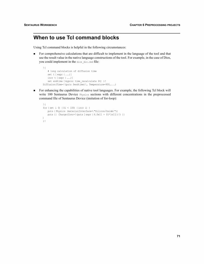
SENTAURUS WORKBENCH CHAPTER 6 PREPROCESSING PROJECTS
When to use Tcl command blocksUsing Tcl command blocks is helpful in the following circumstances:
For comprehensive calculations that are difficult to implement in the language of the tool and thatuse the result value in the native language constructions of the tool. For example, in the case of Dios,you could implement in the dios_dio.cmd file:
!(# long calculation of diffusion timeset t [expr {...}]incr t [expr {...}]set endtime [myproc time_recalculate $t] )!
Diffusion(Time=!(puts $endtime)!, Temperature=900,...)
For enhancing the capabilities of native tool languages. For example, the following Tcl block willwrite 100 Sentaurus Device Physics sections with different concentrations in the preprocessedcommand file of Sentaurus Device (imitation of for-loop):
!(for {set i 0} {$i < 100} {incr i} {
puts {Physics (materialInterface=\"Silicon/Oxide\")}puts {{ Charge(Conc=!(puts [expr {6.0e11 + $i*1e11])!) }}
})!
71

SENTAURUS WORKBENCHCHAPTER 6 PREPROCESSING PROJECTS
72

SENTAURUS WORKBENCH CHAPTER 7 RUNNING PROJECTS
Sentaurus Workbench
CHAPTER 7 Running projects
This chapter discusses how to run projects in Sentaurus Workbench. Projects can be run from the ProjectEditor, the Scheduler (see Schedulers on page 125), or the command line.
From the Project EditorTo run a project:
1. Browse the projects on the tree.
2. Open the project in the Project Editor.
3. Select the nodes or open the required scenario.
To run the selected nodes or scenario:
Project > Project Operations > Run, Ctrl+R, or click the Run button.
The Run Project dialog box is displayed and nodes are assigned, based on the queue definitions andtool assignments of the user. The Run button submits the nodes to the corresponding scheduler orqueues.
In addition, the Execution Time button allows users to define the time at which the nodes are submitted.It is also used to set a delay in the execution of the different nodes.
NOTE Nodes that do not have a ‘done’ status can be run by selecting the remaining option from theNodes box in the Run Project dialog box.
NOTE The particular node(s) or scenario can run by suitably changing the gexpr.
NOTE It is possible to specify the execution order of the nodes from the user preferences. The defaultorder (specified in Miscellaneous preferences, Nodes Running Order) is Breadth_First (seeTable 6 on page 87). This instructs Sentaurus Workbench to execute the nodes by row. Toexecute the nodes by column, change Breadth_First to Depth_First. These settings are onlytaken into account when no node dependencies are specified in the command file.
73
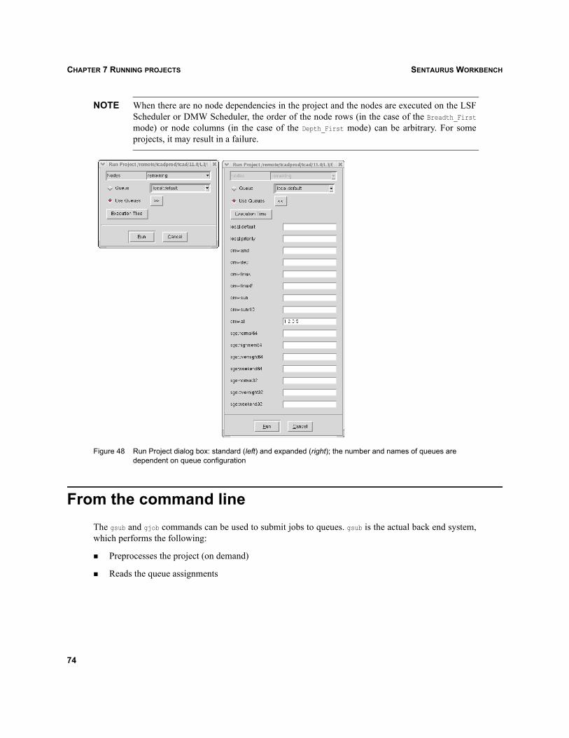
SENTAURUS WORKBENCHCHAPTER 7 RUNNING PROJECTS
NOTE When there are no node dependencies in the project and the nodes are executed on the LSFScheduler or DMW Scheduler, the order of the node rows (in the case of the Breadth_Firstmode) or node columns (in the case of the Depth_First mode) can be arbitrary. For someprojects, it may result in a failure.
Figure 48 Run Project dialog box: standard (left) and expanded (right); the number and names of queues are dependent on queue configuration
From the command lineThe gsub and gjob commands can be used to submit jobs to queues. gsub is the actual back end system,which performs the following:
Preprocesses the project (on demand)
Reads the queue assignments
74

SENTAURUS WORKBENCH CHAPTER 7 RUNNING PROJECTS
Expands the generic expression to determine the node or takes the nodes from the list provided
Submits jobs to the queues, calls gjob on several machines, and executes the jobs:
Usage: gsub [options] (FILENAME | PROJECT)
DESCRIPTIONSubmits specified nodes/jobs to batch system and waits for completion
Example: gsub -e all @STDB@/folder/project
Options:-h[elp] : displays this help message-v[ersion] : displays version information-verbose : displays additional initialization and loading information-e[xpr] "GEXPR" : nodes resulting from the GEXPR expression
-n[odes] [<scenario> | "<list of nodes>"]: remaining nodes in <scenario>, or given node numbers
-q[ueue] "queue name": submits all the jobs to a queue
-m[achine] "machine name": executes all the jobs on a machine
exits after spawning the job-w[ait] : this is used in conjunction with -m option, the gsub
does not wait after master spawns job in the remote machineThe controlling gsub runs on the machine indicated using -m
-startTime : Define a time schedule to launch gsubformat: HH:MM:SS
-delay : Delay between the execution of two nodes in seconds Arguments:FILENAME : text file defining a list of jobsPROJECT : project directory
Note: -m and -q can be used together.
gjob runs the given job or the node of the project locally.
NOTE gjob cannot use the node-queue or tool-queue assignments. It essentially runs each nodelocally.
Example:
gjob -job 2 @STDB@/folder/project
Options:
-h[elp] : displays the help message-v[ersion] : displays version information-verbose : displays additional initialization and run-time information-nopp : no preprocessing; does not produce input files of node
75

SENTAURUS WORKBENCHCHAPTER 7 RUNNING PROJECTS
-p[ack] : does not generate empty lines while preprocessing-nice NUMBER : job scheduling priority-edir DIRNAME : temporary running directory (remote execution)
Arguments:
-j[ob] NAME : job name, or node numberFILENAME : text file defining jobs, orPROJECT : project directory
PreprocessingPreprocessing, which is the initial step before jobs actually run, can be performed separately fromexecution either directly from the GUI (Project > Project Operations > Preprocess or Ctrl+P) or thecommand line by calling gpp.
NOTE gpp is executed as a separate process from the GUI and the result of gpp is stored in the filepreprocessor.log, which can be accessed using Project > Logs > Preprocessor.
NOTE As previously mentioned in gpp and spp on page 7, gpp has been replaced by spp. Thecommand-line options of spp are the same as for gpp, and spp can be used in the same way.
The gpp (preprocessor) preprocesses the given tool input file to standard output or performs a globalpreprocessing pass in a project, for example:
gpp "BOR_IMPL_ENRGY80" "N_DOSE1e15" @STDB@/nmos,process/lig.cmdgpp -verbose @STDB@/nmos,processgpp -expr "scnr_name" @STDB@/nmos,process
Options:-h[elp] : displays this help message-v[ersion] : displays version information-verbose : displays additional initialization and run-time information-i[nput] : generates all of the initial, preprocessed pp* files in project-p[ack] : does not generate empty lines while preprocessing-n[odes] : preprocess just these nodes-e[xpr] : preprocess based on an expression-onlytcl : preprocess only Tcl blocks in command files
Arguments:FILENAME : marked tool input filePROJECT : project directory
76

SENTAURUS WORKBENCH CHAPTER 7 RUNNING PROJECTS
Aborting projectsA project that is running can be aborted from the Project Editor, the projects browser, or the commandline.
To abort a project from the Project Editor:
1. Browse through the tree and select the project to be aborted.
2. Double-click the selection, or right-click and select Open.The project opens in running mode.
3. Project > Project Operations > Abort, or Ctrl+T, or click the corresponding toolbar button.
4. Confirm that the project is to be aborted.
To abort a project from the projects browser:
1. Browse through the tree and select the project to be aborted.
2. Project > Abort Running Project, or Ctrl+T, or right-click and select Project > Abort.
3. Confirm that the project is to be aborted.
To abort a project from the command line:
1. Navigate to the project directory.
2. Create the file gcmds.dat using a text editor.
3. Inside the file, type abort all.The project is aborted without confirmation.
Aborting nodesSpecific running nodes in a project can be aborted from the Project Editor, the Scheduler, or thecommand line.
To abort a running node from the Project Editor:
1. Browse through the tree and select a project.
2. Double-click the selection, or right-click and select Open.The project opens in running mode.
3. Select the node to be aborted.
4. Nodes > Abort, or right-click and select Abort, or click the corresponding toolbar button.
5. Confirm that the node is to be aborted.
77

SENTAURUS WORKBENCHCHAPTER 7 RUNNING PROJECTS
To abort a running node from the Scheduler:
1. Select the node to be aborted from the right pane of the Scheduler, which displays the current list ofrunning nodes.
2. Nodes > Abort, or right-click and select Abort.
3. Confirm that the node is to be aborted.
To abort a running node from the command line:
1. Navigate to the project directory.
2. Create the file gcmds.dat using a text editor.
3. Inside the file, type abort <node(s) numbers>, for example, abort 4 5 7 9.The nodes are aborted without confirmation.
Viewing log or history filesTo view project output files:
1. Select a project.
2. Project > Logs > Project or Project > Logs > History, or right-click and select Project > ViewLog or Project > View History.
Project summaryThe project summary provides a short description of a project that was run. The summary file is storedunder gsummary.txt in the project directory and is generated automatically when the project finishes. Thefollowing information is provided in this file:
Project details:
• Current status
• When the last modification occurred
• Who modified the file
• On which host it was run
Total number of nodes
• Active nodes
• Virtual nodes
Nodes by status: list of nodes sorted by status
78

SENTAURUS WORKBENCH CHAPTER 7 RUNNING PROJECTS
Hosts and execution information followed by a list of hosts and run-time on each host and numberof nodes executed
Total run-time
To view the project summary:
Project > Project Operations > Project Summary or Ctrl+V.
79

SENTAURUS WORKBENCHCHAPTER 7 RUNNING PROJECTS
80

SENTAURUS WORKBENCH CHAPTER 8 CLEANING UP PROJECTS
Sentaurus Workbench
CHAPTER 8 Cleaning up projects
This chapter discusses how to clean up projects in Sentaurus Workbench.
Cleaning up projectsTo clean up a project:
1. Project > Cleanup.
2. Select the required options (see Table 2).
3. Click OK.
NOTE To make the Renumber the tree option available, all preprocessor and simulation dataoptions must be selected.
Table 2 Project cleanup options
Option Description
Preprocessor Data Preprocessed files Set variables
Deletes preprocessor data. Forces preprocessing before running a project.Deletes all preprocessor files (pp*).Deletes variables set by preprocessor from gvars.dat.
Simulation Data Output files Extracted variables
Deletes data left after simulation.Deletes all output files (n<nkey>*).Deletes extracted variables from gvars.dat.
Project Data Clean up the tree Renumber the tree Free the undo stack Log files Project queues Project summary
Deletes data on the project level (in the project directory).Deletes all orphan nodes (not belonging to any scenario) from the tree.Renumbers the tree, column by column.Deletes the undo stack, freeing the associated memory.Deletes log files (preprocessor, history, Sentaurus Workbench, and Optimizer).Deletes the project queues configuration file.Deletes the project summary file.
81

SENTAURUS WORKBENCHCHAPTER 8 CLEANING UP PROJECTS
Figure 49 Cleanup Options dialog box with the default options
Cleaning up the output of nodesTo delete output and preprocessor data of selected nodes:
1. Select required nodes.
2. Nodes > Clean Up Node Output.
3. Select whether you want to delete simulation-extracted variables from gvars.dat.
4. Select whether you want to delete preprocessed variables from gvars.dat.
5. Select output and preprocessor files to be deleted.All output and preprocessor files associated with the selected nodes are preset.
6. Click OK.
Cleaning up projects from the command lineThe batch tool gcleanup is used to clean up a project from command line. For example:
gcleanup -default /folder/project
Options:
-pp : clean up preprocessed files-sv : clean up set variables-res : clean up output files-xv : clean up extracted variables-orp : clean up orphan nodes-ren : renumber (automatically enables pp,sv,xv, and res)-log : clean up log files-sum : clean up gsummary.txt-pq : remove project queue file-uq : remove user queue file-ul : remove user log file-bm : remove bookmarks file
82

SENTAURUS WORKBENCH CHAPTER 8 CLEANING UP PROJECTS
-default : following options are enabled pp, sv, res, xv, sum, orp, and log-unlock : deletes the project status file-a : uses all the above options-v[ersion] : displays version information-verbose : displays additional information-h[elp] : displays this help
Arguments:
PROJECT : project directory (provide complete pathname)
83

SENTAURUS WORKBENCHCHAPTER 8 CLEANING UP PROJECTS
84

SENTAURUS WORKBENCH CHAPTER 9 CONFIGURING SENTAURUS WORKBENCH
Sentaurus Workbench
CHAPTER 9 Configuring Sentaurus Workbench
This chapter discusses how to configure Sentaurus Workbench.
Configuring preferencesTo access the preferences:
1. Edit > User Preferences or F12.
2. Select a preference.
3. Type a new value in the text entry.
4. Click the Accept Changes button or press the Return key.
5. Click Save.
The preferences have four sections: binaries, table, scheduler, and miscellaneous. These are detailedfrom Table 3 to Table 6 on page 87.
Table 3 Binary preferences
Preference name Type Default value Description or reference
Editor File (subentries) From the tool database
Location of different binaries for editing (such as text, Ligament Flow Editor).
Tool File (subentries) From the tool database
Location of different binaries for tools (such as Sentaurus Device, Dios).
Viewer File (subentries) From the tool database
Location of different binaries for viewers (such as Inspect, Tecplot SV).
Table 4 Table preferences
Preference name Type Default value Description or reference
Background Enumeration System default (white or gray) or from .Xdefaults
Background color of table.
Double Click Action Enumeration Show Properties Action when double-click a node: either to show node properties or launch a tool.
Foreground Enumeration System default (black) or from .Xdefaults
Foreground color of table.
85

SENTAURUS WORKBENCHCHAPTER 9 CONFIGURING SENTAURUS WORKBENCH
Font Enumeration System default or from .Xdefaults
Font used in table.
Rows per Variable Integer 1 Specifies the number of rows to be displayed for a variable.
Mouse wheel Integer 1 Number of experiments moved when moving the mouse wheel (if supported).
Title Background Foreground
EnumerationEnumeration
GrayBlack
Background color of table title.Foreground color of table title.
Default View Options Check Virtual Node
Remember Column Width
Tree View
Show Exp PlanShow Node Numbers
Show Parameters Show Pruned Show Tree Show Variables Row Span Show Tool Names
Tool Names in a RowAutomatically
Update Variables
Boolean
Boolean
BooleanBoolean
BooleanBooleanBooleanBooleanBooleanBooleanBooleanBoolean
True
False
FalseFalse
FalseTrueTrueTrueTrueFalseFalseFalse
Default options when showing the tree:View > Tree Options > Check Virtual
NodesView > Column Width > Remember
Column WidthOne of View > Tree Options > Parameter Values, Node Numbers, Host, Date, Execution Time, or VariablesView > Show Experimental PlanView > Tree Options > Show Node
NumbersView > Show ParametersView > Show PrunedView > Show TreeView > Show VariablesView > Tree Options > Row SpanView > Tree Options > Show Tool NamesDisplays an additional row with tool names.Variables > Automatically Update
Variables
Table 5 Scheduler preferences
Preference name Type Default value Description or reference
Scheduler Idle Task Frequency
Job Polling Interval Number of Local
Simultaneous Jobs DMW Nice Level
Nonnegative integerIntegerNonnegative integerInteger (0 to 19)
15000
10001
19
Idle task frequency for updating node statues in scheduler (in milliseconds).The interval between sequential checks of the status of the running job (in milliseconds).Maximum number of jobs that can be launched on the local machine.An argument for the UNIX nice command.
Table 4 Table preferences
Preference name Type Default value Description or reference
86

SENTAURUS WORKBENCH CHAPTER 9 CONFIGURING SENTAURUS WORKBENCH
Table 6 Miscellaneous preferences
Preference name Type Default value Description or reference
Acrobat Reader File From the tool database
Location of Acrobat Reader executable file.
Attached Roots on Start Up
Directory (subentries)
env(STDB)Examples Library
Attached roots when starting up projects browser.
Number of Bookmarks Integer(0 to 200)
10 Number of last projects visited in Project > Recent Projects.
Default Browser File Name of the default browser to visualize the training material.
Spreadsheet Application File Excel for Windows, oocalc for UNIX
Location of the executable for View > Export > Run Spreadsheet Application
Manuals Front Page File From the tool database
Location of front page for Help > Manuals.
HTTP Configuration Proxy Host Proxy Port
StringInteger 80
Configuration required for Web projects download if behind a firewall.
Idle Task Frequency
Automatically Calculate Refresh Rate
Explorer Node Refresh
Boolean
Nonnegative integer
True
3000010000
Idle task frequency for refreshing (milliseconds):When true, calculates the refresh rate automatically.
Projects browser.Status of nodes (when running).
Sentaurus Device Materials Database
Directory Path to the MaterialDB file.
Old Projects Preserve Pruned Nodes
Boolean False When true, preserves pruned nodes when converting old projects.
PCM Library Path File Path to the PCM library.
Tailing File Size Integer 1024 Specifies the maximum size of a node output file, which should be displayed without tailing (in kilobytes). If this size is exceeded, only the tail of the file is displayed in Sentaurus Workbench.
Tailing Lines Number Integer 1000 Specifies the number of lines of a node output file to be displayed in the tailing mode.
Nodes Running Order Enumeration Breadth_First Specifies the order of the running nodes when no predefined node dependencies exist. The alternative is Depth_First.
87

SENTAURUS WORKBENCHCHAPTER 9 CONFIGURING SENTAURUS WORKBENCH
NOTE To restore default settings, run Sentaurus Workbench with the command-line option -default.The scheduler is an independent process; therefore, to use its default settings, savepreferences in the preferences file before calling the scheduler (Edit > User Preferences,then Save).
Tool databasesAll the tools are defined in the tool databases of Sentaurus Workbench. The three tool databases (tooldb)are global, user, and project.
The global tool database is usually set up by the systems administrator and is not writable. Initially, theglobal tool database contains the complete set of TCAD simulation tools and an example of thedefinition of a ‘user tool,’ mytool.
Users can add their own tools or modify existing ones by changing the user or project tool database.Entries in the user tool database complement or override entries in the global tool database, and entriesin the project tool database complement or override entries in the other tool databases.
To access a tool database, select the appropriate command:
Edit > Tool DB > Global.
Edit > Tool DB > User.
Edit > Tool DB > Project.
Simulation tools are divided into several categories:
Sentaurus Process Simulation and Structure Generation
Sentaurus Grid Generation
Sentaurus Device Simulation
Sentaurus Visualization
Exit Warning Boolean False Asks for a confirmation from the user when closing Sentaurus Workbench.
Remote GSUB Path File Location of the gsub executable in the remote machine used during remote computing.
Temp Directory Directory STDB/tmp Location of temporal directory of Sentaurus Workbench.
Training Documentation File Path to the training material.
Table 6 Miscellaneous preferences
Preference name Type Default value Description or reference
88

SENTAURUS WORKBENCH CHAPTER 9 CONFIGURING SENTAURUS WORKBENCH
Extraction
Utilities
Process Simulation and Structure Generation (Other)
Device Simulation (Other)
The order in which these categories are displayed (from top to bottom) reflects the order in which thecorresponding simulation phases are linked to each other (apart from the utilities). For example, it is notusual for a grid generation tool to precede a process simulation tool in the tool flow.
NOTE The global and user tool databases are loaded when starting Sentaurus Workbench or anybatch tools such as gsub and gjob. The project tool database is loaded with the project and isapplied only to that project.
User functions can be defined in the user and project tool databases. These functions can customizestandard Sentaurus Workbench preprocessing.
For example, users can redefine the standard value extraction algorithm (see Extracted variables onpage 64). First, create your own extract function in the user or project tool database:
proc ::myextract_vars { wdir from_file nkey } {...
}
Then, in the same tool database file, redefine the tool epilogue. In the case of Sentaurus Process, it wouldlook like:
set WB_tool(sprocess,epilogue) { ::myextract_vars $wdir @stdout@ @node@ }
NOTE It is necessary to provide the ‘::’ prefix for user-defined functions in a project tool database.The project tool database is stored in a separate Tcl namespace for each of the loaded projects.
Tool databases can be modified in two ways: using the standard text editor (SEdit) or a special graphicaluser interface integrated into Sentaurus Workbench, referred to as the Tool DB Editor. Since all thesettings are available through the text editor, the Tool DB Editor provides only frequently used andpopular settings of the tool databases to modify.
Delimiters of a tool database fileTo allow the Tool DB Editor to work on the different tool databases, it was necessary to ‘encapsulate’some data. This encapsulation is implemented by using delimiters.
Every tool database file must contain these delimiters; otherwise, the editor will not work.
89

SENTAURUS WORKBENCHCHAPTER 9 CONFIGURING SENTAURUS WORKBENCH
Table 7 lists the delimiters that are available to be used in the tool databases.
The following are examples of the use of delimiters:
#SPECIAL_SETTINGS BEGINglobal tcl_platformglobal env#SPECIAL_SETTINGS END
#TOOL BEGIN inspectset WB_tool(inspect,category) visualization...set WB_tool(inspect,visual_category) visualizationlappend WB_tool(all) inspect#TOOL END
Table 7 Delimiters
Delimiter Description and use
#BEGIN FILE Instructs the Tool DB Editor that a tool database file will be read.
#SPECIAL_SETTINGS BEGIN In this section, the global variables are defined such as tcl_platform and env.
#SPECIAL_SETTINGS END Ends this section.
#FILE-TYPES BEGIN This section is for the definition of the different file types used by the different tools.
#FILE-TYPES END Ends this section.
#DEFAULT VIEWER BEGIN In this section, the default viewer is defined.
#DEFAULT VIEWER END Ends this section.
#TOOL BEGIN <TOOLNAME> This section is for the definition of a new tool, for example:#TOOL BEGIN gsched.
#TOOL END Ends this section.
#INPUT-EDITORS BEGIN In this section, all the editors for the different input command files are defined.
#INPUT-EDITORS END Ends this section.
#OUTPUT-VIEWERS BEGIN This section is for the definition of the output viewers.
#OUTPUT-VIEWERS END Ends this section.
#CONDITION BEGIN (<KEYWORD>)
This section is used to mark different conditions, for example, the use of different binaries according to the current operating system. <KEYWORD> is the reference to a tool database specification and is reserved for future releases.
#CONDITION END Ends this section.
#TCL-SOURCE BEGIN This section is for the definition of user-specific Tcl procedures.
#TCL-SOURCE END Ends this section.
90

SENTAURUS WORKBENCH CHAPTER 9 CONFIGURING SENTAURUS WORKBENCH
#OUTPUT-VIEWERS BEGINset WB_viewer(all) [list]set WB_viewer(text,files) "*{n,N,pp}@node@\{.,_???.,_sdevice.\}\{???,????\}"set WB_viewer(text,label) "All Text Files (SEdit)"set WB_viewer(text,nbfiles) 0set WB_viewer(text,cmd_line) @files@set WB_viewer(text,exec_dir) "@pwd@"set WB_binaries(viewer,text) $app_data(bin_dir)/seditlappend WB_viewer(all) text...#CONDITION BEGIN (after,viewer,dmp/dios)if { [ string match $tcl_platform(platform) "windows" ] } {
set WB_binaries(viewer,dmp/dios) "[file join $env(ComSpec)] /c $app_data(bin_dir)/dios"}#CONDITION ENDlappend WB_viewer(all) dmp/dios#OUTPUT-VIEWERS END
Tool DB EditorThe Tool DB Editor has been written according to the structure of the tool database files. With thedifferent delimiters, the tool database has been divided in sections. These sections are displayed now onthe main graphical user interface of the Tool DB Editor.
Graphical user interface
To open the Tool DB Editor, from the menu bar of Sentaurus Workbench, select one of the threeavailable tool databases:
Edit > Tool DB > Global.
Edit > Tool DB > User.
Edit > Tool DB > Project.
Figure 50 Tool DB Editor dialog box
91

SENTAURUS WORKBENCHCHAPTER 9 CONFIGURING SENTAURUS WORKBENCH
To save changes, click Save. A new tool database will be written.
To quit without saving, click Cancel.
To work on the tools or other settings, select the appropriate option and click OK.
Each of the options available from the Tool DB Editor is discussed.
File Types
This interface is used to set the values for the different file types, which are encapsulated by the#FILE-TYPES BEGIN and #FILE-TYPES END delimiters.
Figure 51 Set File Types dialog box
NOTE If you open a write-protected tool database file (for example, the global tool database), youcannot save any settings. For this reason, the Apply and Delete buttons are not available.
The functions of the buttons of the Set File Types dialog box are:
Click Apply to save settings.
The settings are saved in the memory but not in the tool database file. To save your settings in thetool database file, click Save on the Tool DB Editor (see Figure 50 on page 91).
Click Delete to delete settings.
Click Exit to discard any changes.
Tools
The different fields in the tool settings are generated according to the array indices in the tool databasefile. If a new index is inserted in the tool database file, the corresponding field will be generated for alltools when the Tool DB Editor is launched. For example:
#TOOL BEGIN <toolname>set WB_tool(<toolname>,category) processset WB_tool(<toolname>,acronym) fpsset WB_tool(<toolname>,after) [list START cshell sde noffset3d]
The corresponding fields in the Tool DB Editor for these settings would be category, acronym, and after.
92

SENTAURUS WORKBENCH CHAPTER 9 CONFIGURING SENTAURUS WORKBENCH
Figure 52 Tools dialog box
The only exceptions have been made for icons, binaries, manuals, and the cleanup patterns. In the tooldatabase, the cleanup patterns are defined as:
set WB_tool(sprocess,output,files) "n@node@_@index@_fps.* \n@node@_@index@_mdr.* \n@node@*.{dmf,plx,PLX} \n@node@_fps.{log,dmf,grd,grd.gz,dat,dat.gz,plx,PLX,out,err,sta,job,tdr} \p@node@*.plx n@[email protected] \n@node@_mdr.{cmd,bnd}"
The corresponding settings will appear inside the cleanup field.
NOTE If the values consist of a list, use a backslash to separate the different list elements. Otherwise,the Tool DB Editor will not read all elements.
The available options are:
To create a new tool, select the New Tool option.
To define the input or output files for a given tool, select the Set Tool Input List or Set Tool OutputList option.
To create a new field, select the Create a New Field option.
93

SENTAURUS WORKBENCHCHAPTER 9 CONFIGURING SENTAURUS WORKBENCH
Figure 53 Output List dialog box for TSUPREM-4
In Figure 53, you can define the input or output files for a given tool. In the left pane are all of theavailable file types. Using the >> or << buttons, you can add or remove files from the input or outputfile list. The corresponding settings in the tool database would be:
set WB_tool(<toolname>,input) [list commands fdmp plot grid doping pref]......set WB_tool(<toolname>,output) [list log boundary plot tdr]
If the Set Tool Input List or Set Tool Output List option is selected, a new dialog box will be displayed(see Figure 54 on page 95).
The values of these fields correspond to the settings in the input or output file section of the tooldatabase:
set WB_tool(<tool>,input|output,<file>,file) <value_1>set WB_tool(<tool>,input|output,<file>,input) <value_2>set WB_tool(<tool>,input|output,<file>,oldfile) <value_3>set WB_tool(<tool>,input|output,<file>,newfile) <value_4>set WB_tool(<tool>,input|output,<file>,label) <value_5>set WB_tool(<tool>,input|output,<file>,editor) <value_6>set WB_tool(<tool>,input|output,<file>,parametrized) <value_7>set WB_tool(<tool>,input|output,<file>,output) <value_8>set WB_tool(<tool>,input|output,<file>,user) <value_9>set WB_tool(<tool>,input|output,<file>,files) <value_10>set WB_tool(<tool>,input|output,<file>,preamble) <value_11>set WB_tool(<tool>,input|ouput,<file>,cmd) <value_11>
94

SENTAURUS WORKBENCH CHAPTER 9 CONFIGURING SENTAURUS WORKBENCH
Figure 54 Output Settings dialog box
Input Editors
The values of the fields correspond to the settings:
set WB_binaries(editor,<Editor>) <Path>
Figure 55 Editors dialog box
95
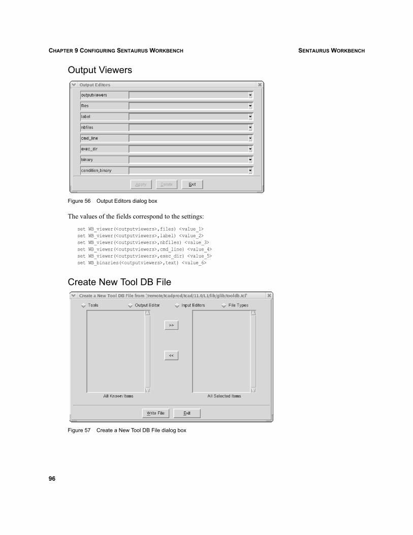
SENTAURUS WORKBENCHCHAPTER 9 CONFIGURING SENTAURUS WORKBENCH
Output Viewers
Figure 56 Output Editors dialog box
The values of the fields correspond to the settings:
set WB_viewer(<outputviewers>,files) <value_1>set WB_viewer(<outputviewers>,label) <value_2>set WB_viewer(<outputviewers>,nbfiles) <value_3>set WB_viewer(<outputviewers>,cmd_line) <value_4>set WB_viewer(<outputviewers>,exec_dir) <value_5>set WB_binaries(<outputviewers>,text) <value_6>
Create New Tool DB File
Figure 57 Create a New Tool DB File dialog box
96
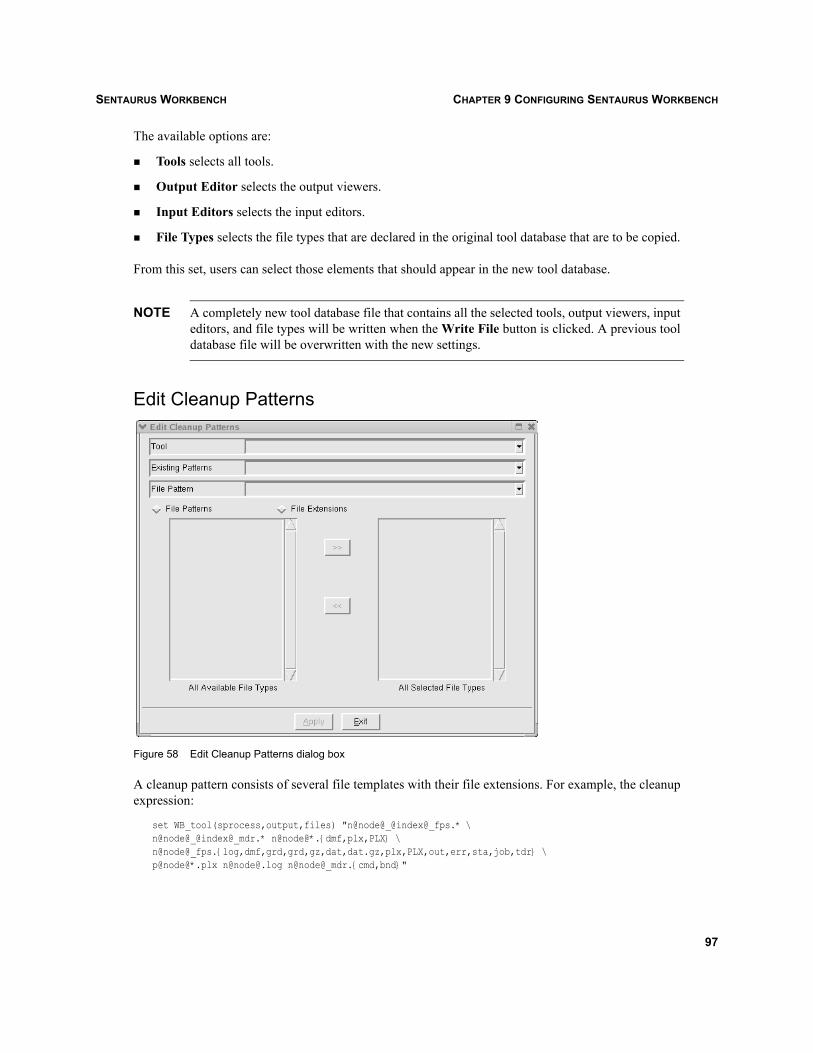
SENTAURUS WORKBENCH CHAPTER 9 CONFIGURING SENTAURUS WORKBENCH
The available options are:
Tools selects all tools.
Output Editor selects the output viewers.
Input Editors selects the input editors.
File Types selects the file types that are declared in the original tool database that are to be copied.
From this set, users can select those elements that should appear in the new tool database.
NOTE A completely new tool database file that contains all the selected tools, output viewers, inputeditors, and file types will be written when the Write File button is clicked. A previous tooldatabase file will be overwritten with the new settings.
Edit Cleanup Patterns
Figure 58 Edit Cleanup Patterns dialog box
A cleanup pattern consists of several file templates with their file extensions. For example, the cleanupexpression:
set WB_tool(sprocess,output,files) "n@node@_@index@_fps.* \n@node@_@index@_mdr.* n@node@*.{dmf,plx,PLX} \n@node@_fps.{log,dmf,grd,grd,gz,dat,dat.gz,plx,PLX,out,err,sta,job,tdr} \p@node@*.plx n@[email protected] n@node@_mdr.{cmd,bnd}"
97
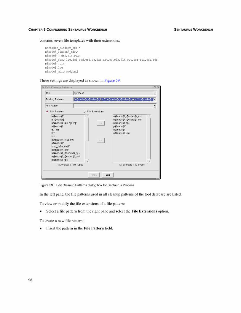
SENTAURUS WORKBENCHCHAPTER 9 CONFIGURING SENTAURUS WORKBENCH
contains seven file templates with their extensions:
nn@node@_@index@_fps.*n@node@_@index@_mdr.*n@node@*.{dmf,plx,PLX}n@node@_fps.{log,dmf,grd,grd,gz,dat,dat.gz,plx,PLX,out,err,sta,job,tdr}p@node@*.plxn@[email protected]@node@_mdr.{cmd,bnd}
These settings are displayed as shown in Figure 59.
Figure 59 Edit Cleanup Patterns dialog box for Sentaurus Process
In the left pane, the file patterns used in all cleanup patterns of the tool database are listed.
To view or modify the file extensions of a file pattern:
Select a file pattern from the right pane and select the File Extensions option.
To create a new file pattern:
Insert the pattern in the File Pattern field.
98
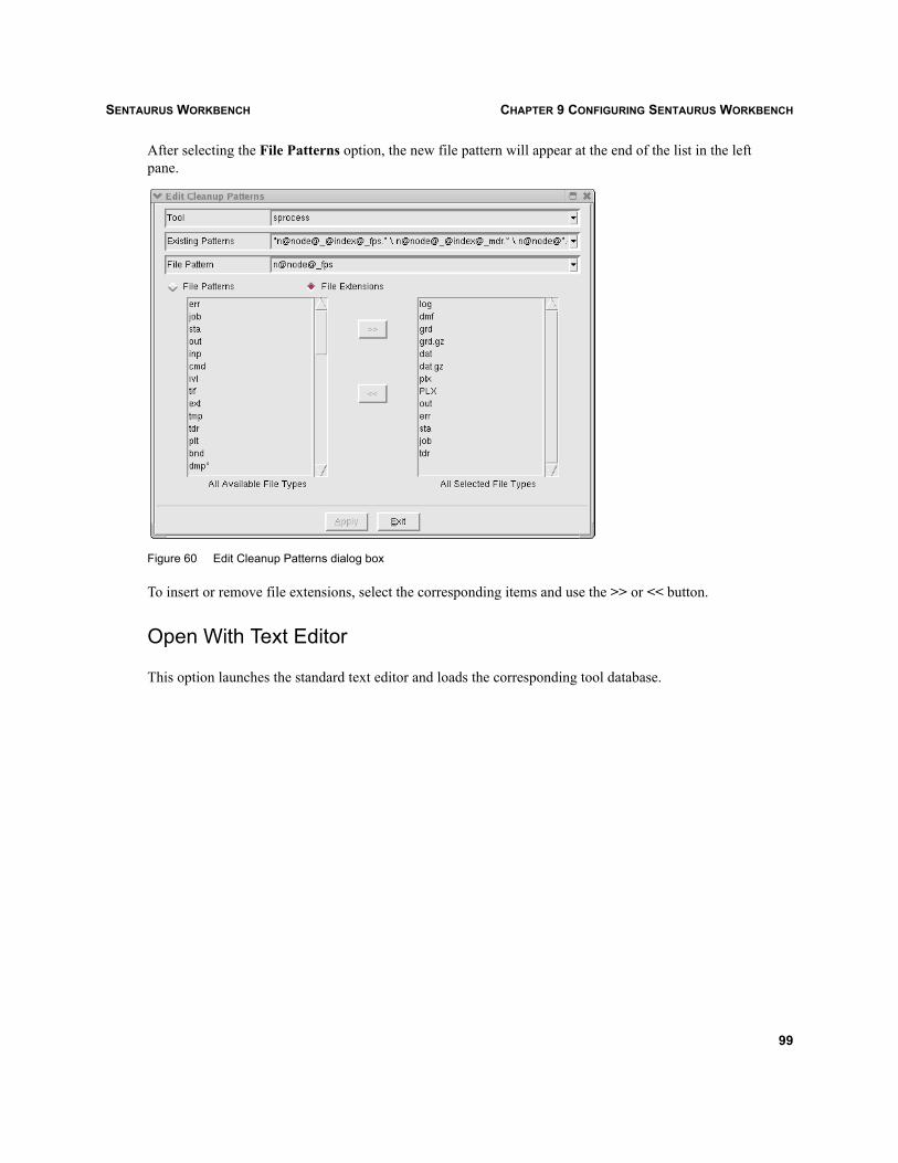
SENTAURUS WORKBENCH CHAPTER 9 CONFIGURING SENTAURUS WORKBENCH
After selecting the File Patterns option, the new file pattern will appear at the end of the list in the leftpane.
Figure 60 Edit Cleanup Patterns dialog box
To insert or remove file extensions, select the corresponding items and use the >> or << button.
Open With Text Editor
This option launches the standard text editor and loads the corresponding tool database.
99

SENTAURUS WORKBENCHCHAPTER 9 CONFIGURING SENTAURUS WORKBENCH
100

SENTAURUS WORKBENCH CHAPTER 10 REMOTE COMPUTING
Sentaurus Workbench
CHAPTER 10 Remote computing
This chapter discusses how to use remote computing from Sentaurus Workbench.
Using remote computingRemote computing permits users to launch jobs on clusters from their PC or laptop. The concept ofremote computing is to allow users to use powerful machines without having to stay connected to thenetwork when all submitted jobs are finished. The requirements for remote computing are:
rsh or ssh to machine is silent, that is:
> rsh machine_name echo coucoucoucou
If rsh is not possible, users can configure ssh to connect to the cluster by setting the environmentvariable GSUB_RSH_PATH to point to the appropriate executable.
gsub (the back-end executable) is in the path of the user environment. If gsub is not available, the usermust configure the preference file at the remote machine to point to the correct gsub. This can betested by using:
rsh machine_name gsub -vSynopsys TCAD Software Release Y-2006.06Sentaurus Workbench gsub Version 12.0.4Compiled Fri Apr 14 02:20:39 CEST 2006 on redhat118 (ia32, linux_gnu)Copyright (c) 1994-2006 Synopsys, Inc.
If all these requirements are satisfied, remote computing can be activated from the Sentaurus WorkbenchGUI:
Scheduler > Remote Computing.
NOTE Click the Reload project icon or Project > Reload to obtain information about the status ofthe nodes.
Remote computing can also be used from the command line using gsub, for example:
gsub -verbose -m machine A -q local:default @STDB@/nmos,process
This command runs the project located in the directory @STDB@/nmos,process on the remote machine A inthe local queue.
The remote computing feature allows users to copy a project automatically from a local machine to adestination machine, to execute it there, and to copy the results back to the local machine.
101

SENTAURUS WORKBENCHCHAPTER 10 REMOTE COMPUTING
To avoid using tools such as gzip or tar for project synchronization, rsync is used to copy projects to aremote machine and, if necessary, to copy the simulation results back. rsync uses rsh for itscommunications. As previously mentioned, it is important that rsh is configured in silent mode.Otherwise, the password request will be treated by Sentaurus Workbench as an error.
To run rsync, some environment variables must be set:
On UNIX:setenv RSYNC_PATH = <path to rsync binary>
If RSYNC_PATH is not set, Sentaurus Workbench will use the standard installed rsync.
If users want to use rsync with ssh instead of rsh, the environment variable RSYNC_RSH must be set tothe path to the ssh binary:
setenv RSYNC_RSH <path to ssh binary>
On Windows:RSYNC_PATH = <path to rsync binary>
If RSYNC_PATH is not set, Sentaurus Workbench will search the rsync binary in the System32 directory.
Follow the installation instructions of your rsync supplier, for example:
If the rsync version that you use requires some additional settings: Create a batch file (rsetup.bat) inthe rsync directory:
set PATH=<PATH TO RSYNC>;%PATH%set CYGWIN=binmode ttyset TERM=ansiset USERNAME=<USERNAME>set HOME= <HOME_DIRECTORY_RSYNC>set RSYNC_RSH=ssh.exe
To force gsub to copy back the simulation results, the option -w must be selected. If not, gsub will onlycopy and execute the project on a remote machine.
102
SENTAURUS WORKBENCH CHAPTER 11 INTEGRATING SENTAURUS WORKBENCH WITH OTHER TOOLS
Sentaurus Workbench
CHAPTER 11 Integrating Sentaurus Workbench with other tools
This chapter discusses how to use other tools and features from Sentaurus Workbench.
Visualizing response surfacesThis tool is used to display in Tecplot SV a surface corresponding to a response surface model (RSM).To use this tool:
1. Run Sentaurus Workbench and open a project containing response values.
2. Optimization > RSM Visualization.
In the first step of RSM visualization (see Figure 61 on page 104, left), select the following options todefine the RSM to be visualized:
Scenario The scenario in the loaded project that will be used to make the RSM.
X axis The parameter to be used as the x-axis of the plot.
Y axis The parameter to be used as the y-axis of the plot.
Z axis The response to be used as the z-axis of the plot.
Type The type of RSM model (standard or Kriging).
Model The RSM model degree (first order or second order).
After these values are set, click Next to continue.
103

SENTAURUS WORKBENCHCHAPTER 11 INTEGRATING SENTAURUS WORKBENCH WITH OTHER TOOLS
Figure 61 RSM Visualization - Step 1 (left) and RSM Visualization - Step 2 (right)
In the second step (see Figure 61, right), select the values that determine the plot ranges and values forthe parameters other than the ones selected to be visualized on the x-axis and y-axis:
Xmin Lowest value of the parameter to be plotted on the x-axis. By default, it takesthe minimum value of such a parameter.
Xmax Highest value of the parameter to be plotted on the x-axis. By default, it takesthe maximum value of such a parameter.
Xnpts Number of points in the x-axis range; the default is 30.
Ymin Lowest value of the parameter to be plotted on the y-axis. By default, it takesthe minimum value of such a parameter.
Ymax Highest value of the parameter to be plotted on the y-axis. By default, it takesthe maximum value of such a parameter.
Ynpts Number of points in the y-axis range; the default is 30.
Dimension Dimension of the Tecplot1 plot.
1. Tecplot is a registered trademark of Tecplot, Inc., Bellevue, WA, U.S.A.
104
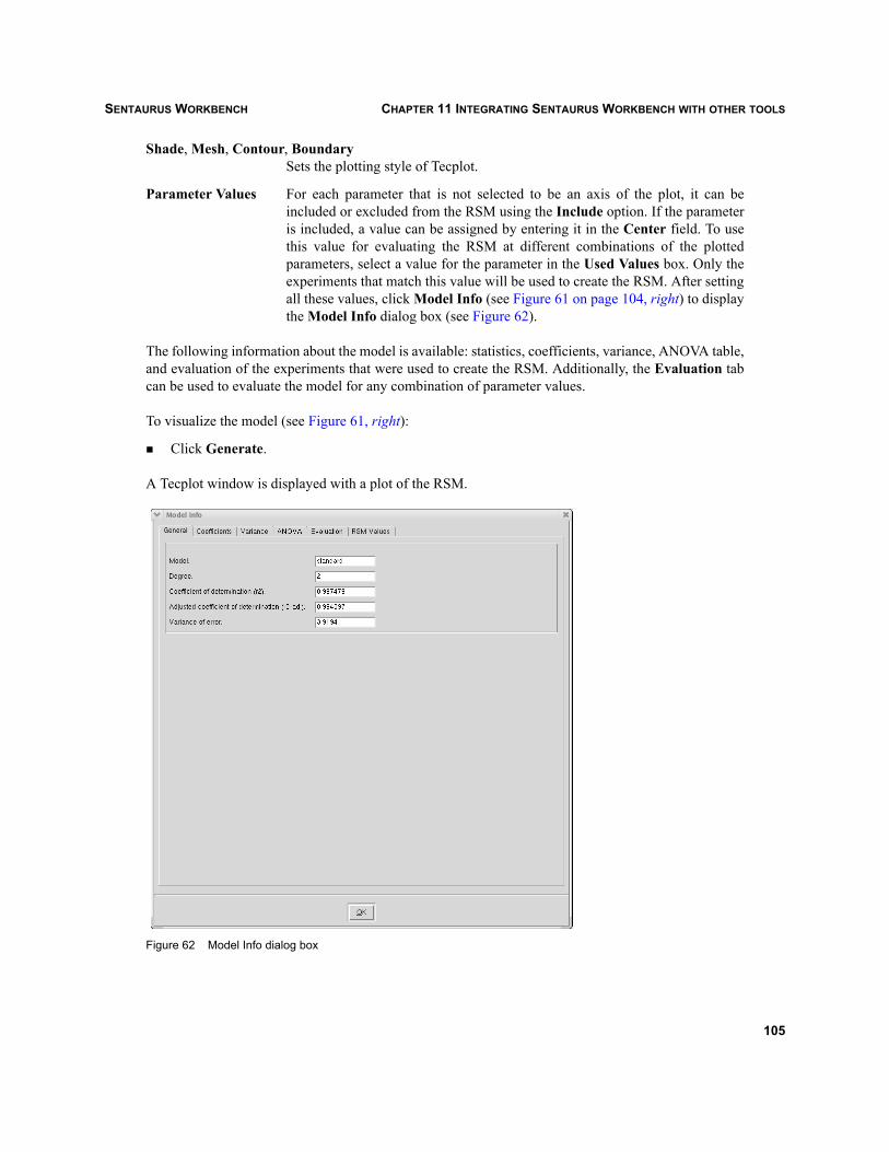
SENTAURUS WORKBENCH CHAPTER 11 INTEGRATING SENTAURUS WORKBENCH WITH OTHER TOOLS
Shade, Mesh, Contour, BoundarySets the plotting style of Tecplot.
Parameter Values For each parameter that is not selected to be an axis of the plot, it can beincluded or excluded from the RSM using the Include option. If the parameteris included, a value can be assigned by entering it in the Center field. To usethis value for evaluating the RSM at different combinations of the plottedparameters, select a value for the parameter in the Used Values box. Only theexperiments that match this value will be used to create the RSM. After settingall these values, click Model Info (see Figure 61 on page 104, right) to displaythe Model Info dialog box (see Figure 62).
The following information about the model is available: statistics, coefficients, variance, ANOVA table,and evaluation of the experiments that were used to create the RSM. Additionally, the Evaluation tabcan be used to evaluate the model for any combination of parameter values.
To visualize the model (see Figure 61, right):
Click Generate.
A Tecplot window is displayed with a plot of the RSM.
Figure 62 Model Info dialog box
105

SENTAURUS WORKBENCHCHAPTER 11 INTEGRATING SENTAURUS WORKBENCH WITH OTHER TOOLS
Taurus Workbench to Sentaurus Workbench converterTo import a Taurus Workbench (TWB) project into the Sentaurus Workbench (SWB) environment:
Double-click the TWB project folder.
Sentaurus Workbench will search for a file called <projectName>.vfl. If this file exists, then you have avalid TWB project and conversion starts.
Figure 63 Projects Browser
After that, the converter will ask for the destination path to store the converted project (see Figure 64).
Figure 64 Save Project As dialog box
During the conversion, the converter will perform the following steps:
Generate a new SWB project.
Create a tool flow according to the existing one inside the TWB project.
Create experiments according to the experiment tree structure and the ‘control values’ in the TWBproject.
Copy all relevant files like the mask files and the root wafer file.
Create simulator command files according to the instructions that are stored in the differentmodules, inside the .vfl file.
106

SENTAURUS WORKBENCH CHAPTER 11 INTEGRATING SENTAURUS WORKBENCH WITH OTHER TOOLS
Figure 65 Taurus Workbench project converted to Sentaurus Workbench project
RestrictionsTaurus Workbench allows tool splits inside the experiment tree on a more general basis than SentaurusWorkbench. In Sentaurus Workbench, a split is defined by different parameter values, while in TaurusWorkbench, a split can be defined by different tools or different command files (for the same tool).
The converter has three strategies to detect tool splits:
1. Different tool names on the same tree level.
2. Different module names on the same tree level.
3. Different number of command lines for the simulators on the same tree level.
If an imported project has fewer experiments than the original one in Taurus Workbench, then open theproject in Taurus Workbench and rename all modules on the corresponding tree level.
107
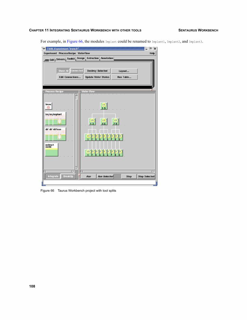
SENTAURUS WORKBENCHCHAPTER 11 INTEGRATING SENTAURUS WORKBENCH WITH OTHER TOOLS
For example, in Figure 66, the modules Implant could be renamed to Implant1, Implant2, and Implant3.
Figure 66 Taurus Workbench project with tool splits
108
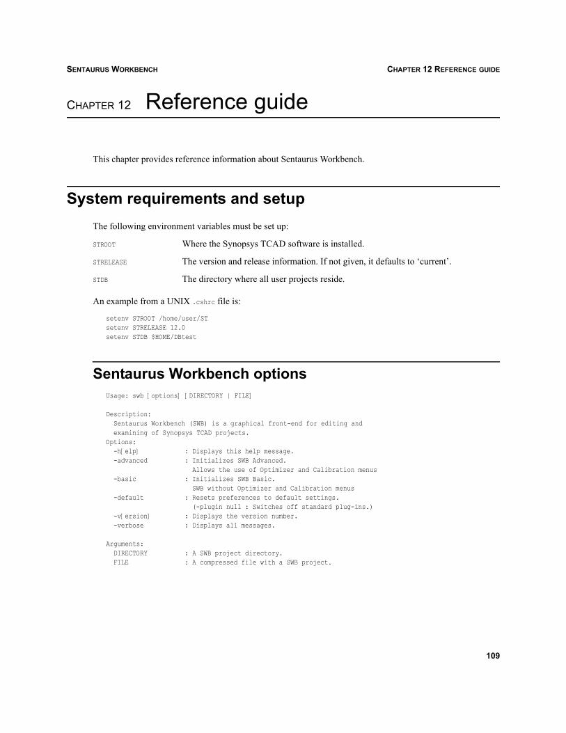
SENTAURUS WORKBENCH CHAPTER 12 REFERENCE GUIDE
Sentaurus Workbench
CHAPTER 12 Reference guide
This chapter provides reference information about Sentaurus Workbench.
System requirements and setupThe following environment variables must be set up:
STROOT Where the Synopsys TCAD software is installed.
STRELEASE The version and release information. If not given, it defaults to ‘current’.
STDB The directory where all user projects reside.
An example from a UNIX .cshrc file is:
setenv STROOT /home/user/STsetenv STRELEASE 12.0setenv STDB $HOME/DBtest
Sentaurus Workbench optionsUsage: swb [options] [DIRECTORY | FILE]
Description:Sentaurus Workbench (SWB) is a graphical front-end for editing andexamining of Synopsys TCAD projects.
Options:-h[elp] : Displays this help message.-advanced : Initializes SWB Advanced.
Allows the use of Optimizer and Calibration menus-basic : Initializes SWB Basic.
SWB without Optimizer and Calibration menus-default : Resets preferences to default settings.
(-plugin null : Switches off standard plug-ins.)-v[ersion] : Displays the version number.-verbose : Displays all messages.
Arguments:DIRECTORY : A SWB project directory.FILE : A compressed file with a SWB project.
109
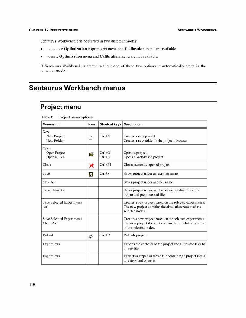
SENTAURUS WORKBENCHCHAPTER 12 REFERENCE GUIDE
Sentaurus Workbench can be started in two different modes:
-advanced: Optimization (Optimizer) menu and Calibration menu are available.
-basic: Optimization menu and Calibration menu are not available.
If Sentaurus Workbench is started without one of these two options, it automatically starts in the-advanced mode.
Sentaurus Workbench menus
Project menuTable 8 Project menu options
Command Icon Shortcut keys Description
New New Project New Folder
Ctrl+N Creates a new projectCreates a new folder in the projects browser
Open Open Project Open a URL
Ctrl+OCtrl+U
Opens a projectOpens a Web-based project
Close Ctrl+F4 Closes currently opened project
Save Ctrl+S Saves project under an existing name
Save As Saves project under another name
Save Clean As Saves project under another name but does not copy output and preprocessed files
Save Selected Experiments As
Creates a new project based on the selected experiments. The new project contains the simulation results of the selected nodes.
Save Selected Experiments Clean As
Creates a new project based on the selected experiments. The new project does not contain the simulation results of the selected nodes.
Reload Ctrl+D Reloads project
Export (tar) Exports the contents of the project and all related files to a .gzp file
Import (tar) Extracts a zipped or tarred file containing a project into a directory and opens it
110

SENTAURUS WORKBENCH CHAPTER 12 REFERENCE GUIDE
Edit menu
Command Icon Shortcut keys Description
Project Operations Preprocess
Preprocess Tcl Blocks Run Abort Project Summary
Ctrl+PCtrl+BCtrl+RCtrl+TCtrl+Y
Preprocesses current projectPreprocesses Tcl command blocksRuns current projectAborts running projectShows project summary
Readme Opens an editor with the project readme file
Logs Preprocessor Project History
Ctrl+JCtrl+H
Options for viewing project-related logs:View preprocessor logView project logView history log
File Browser F11 Browses directory files of project
Clean Up Ctrl+L Shows several project cleanup options
Rename Renames project in the projects browser
Unlock Ctrl+K Unlocks project and sets it in edit mode
Documentation Opens a project documentation file greadme.pdf in Adobe Acrobat Reader
Recent Projects List of recently opened projects
Exit Ctrl+Q Exits Sentaurus Workbench
Table 9 Edit menu options
Command Icon Shortcut keys Description
Undo Ctrl+Z Undoes previous operation
Command Prompt Here Opens a command prompt in the selected project
Cut Ctrl+X Cuts a selection of experiments
Copy Ctrl+C Copies a selection of experiments
Paste Ctrl+V Pastes a cut or copied selection of experiments
Delete Delete key Deletes currently selected item
Stop Loading Esc key Stops the loading of a project and closes it
Table 8 Project menu options
111

SENTAURUS WORKBENCHCHAPTER 12 REFERENCE GUIDE
Scheduler menu
Command Icon Shortcut keys Description
Attach Root Attaches a new root in the projects browser
Detach Root Detaches root selected in the projects browser
Tool DB Global User Project
Options for viewing tool database files:Global tool databaseUser tool databaseProject tool database
User Preferences F12 Opens Preferences dialog box
Table 10 Scheduler menu options
Command Icon Shortcut keys Description
Show/Hide Scheduler Opens Scheduler
Set Scan Root Optimizes scheduler scanning by setting a different root
Configure Queues User Queues Project Queues User DMW Queues Project DMW Queues Edit User Queues Edit Project Queues
Configures tool associations and node expressions:Configures user and project queues, using user interface
Configures user and project DMW queues, also stored under user_queues, using user interfaceEdits user queues using standard text editorEdits project queues using standard text editor
View Global Queues Views the global queue settings in read-only mode
Remote Computing Launches the back end scheduler on a remote machine
Table 9 Edit menu options
112

SENTAURUS WORKBENCH CHAPTER 12 REFERENCE GUIDE
View menuTable 11 View menu options
Command Icon Shortcut keys Description
Tree Options Show Node Numbers
Show Tool NamesCheck Virtual Nodes
Row Span Parameter Values Node Numbers Host Date Execution Time Variables
F9Ctrl+F9Ctrl+0
Ctrl+1Ctrl+2Ctrl+3Ctrl+4Ctrl+5Ctrl+6
Submenu for viewing tree options:When true, always displays node numbersWhen true, shows rollover text with names of toolsWhen true, checks the node status of virtual nodes when runningWhen true, spans cells with nodes that have childrenShows parameter values in node table cellsShows node numbers in node table cellsShows running host in node table cellsShows running date in node table cellsShows execution time in node table cellsShows variables information in node table cells
Show Tree F1 When true, shows simulation tree
Show Experimental Plan F2 When true, shows experimental plan
Show Parameters F3 When true, shows parameter information
Show Variables F4 When true, shows variable information
Show Pruned F8 When true, shows pruned and orphan nodes
Zoom In Ctrl+Plus sign Zooms in to the project view
Zoom Out Ctrl+Minus sign
Zooms out of the project view
Zoom Off Ctrl+0 Resets zoom to the default
Export Text File Plot File Run Inspect Run Spreadsheet
Application
Submenu for exporting current project view:Exports view into a Microsoft Excel–compatible fileExports view into an Inspect-compatible fileExports view into a file and opens it with InspectExports view into a file and opens it with a spreadsheet application configurable in user preferences
Column Width Remember Column Width Save Column Width Restore Column Width Show/Hide Columns
F6Ctrl+F6
When true, remembers columns widthSaves column width to the diskSets column width to the defaultDisplays dialog box to show or hide columns
Refresh F5 Refreshes the tree or browser view
Properties Shows the basic properties of the tree
113

SENTAURUS WORKBENCHCHAPTER 12 REFERENCE GUIDE
Scenario menu
Tool menu
Table 12 Scenario menu options
Command Icon Shortcut keys Description
Add Adds a new scenario to the tree
Delete Deletes scenarios from the tree
Next Alt+ Shows next scenario in the tree
Previous Alt+ Shows previous scenario in the tree
Lock Locks all nodes of current scenario from preprocessing
Unlock Unlocks all nodes of current scenario for preprocessing
Preprocess Preprocesses current scenario
Table 13 Tool menu options
Command Icon Shortcut keys Description
Add Insert key Adds a new tool, parameter, experiment, or variable to the tree
Delete Delete key Deletes selected tool, parameter, experiment, or variable from the tree
Properties Shows basic properties of selected tool
Edit Input Opens submenu for editing input files of selected tool
Import File Submenu for importing input files of selected tool
All DB Tools Displays a dialog box with all available database tools
Tool DB Info Shows input and output file names of selected tool according to the tool database
Preprocess Preprocesses all nodes belonging to the selected tool(s)
Hide Hides selected tool(s)
Show All Shows all hidden tools
→
←
114

SENTAURUS WORKBENCH CHAPTER 12 REFERENCE GUIDE
Parameter menu
Experiments menu
Table 14 Parameter menu options
Command Icon Shortcut keys Description
Add Insert key Adds a parameter to the flow
Delete Delete key Deletes selected parameter from the flow
Properties Shows properties of selected parameter
Add Values Displays dialog box to add values to the selected parameter
Edit Values Displays dialog box to edit values of the selected parameter
Remove Value Removes a value of the selected parameter
Hide Hides selected parameter(s)
Show All Shows all hidden parameters
Table 15 Experiments menu options
Command Icon Shortcut keys Description
Create Default Experiment Creates a new experiment for a specified scenario; default values are used for all parameters
Add New Experiment Insert key Adds a new experiment to the tree (the default values are preset to a selected experiment if there is one)
Add Values Adds parameter values to all experiments (full factorial) or selected experiments
Delete Experiments Delete key Deletes selected experiments from the flow
DoE DoE Wizard Taguchi Wizard
Design-of-experiments options
Import From File Imports experiments from a text file
Properties Shows parameter values of selected experiment
Sort Experiments Sorts experiments according to a defined parameter
115
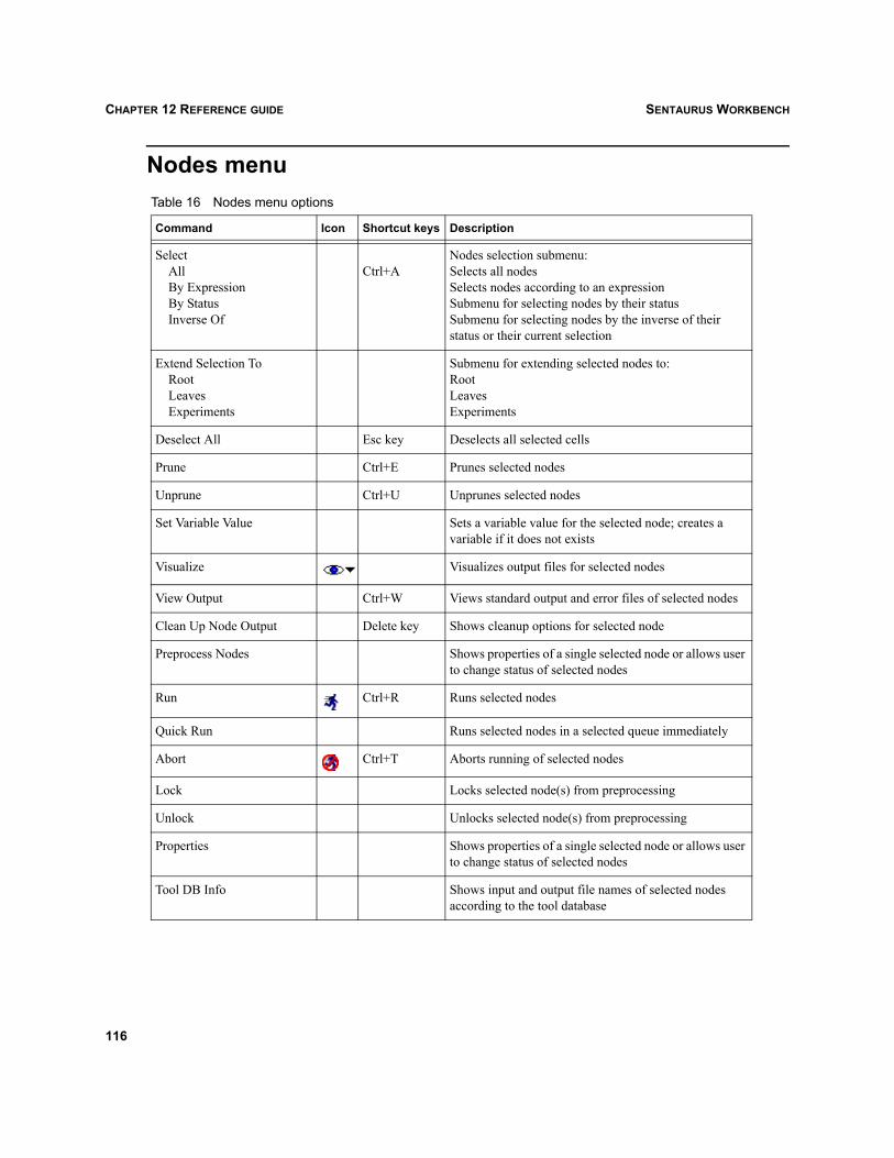
SENTAURUS WORKBENCHCHAPTER 12 REFERENCE GUIDE
Nodes menuTable 16 Nodes menu options
Command Icon Shortcut keys Description
Select All By Expression By Status Inverse Of
Ctrl+ANodes selection submenu:Selects all nodesSelects nodes according to an expressionSubmenu for selecting nodes by their statusSubmenu for selecting nodes by the inverse of their status or their current selection
Extend Selection To Root Leaves Experiments
Submenu for extending selected nodes to:RootLeavesExperiments
Deselect All Esc key Deselects all selected cells
Prune Ctrl+E Prunes selected nodes
Unprune Ctrl+U Unprunes selected nodes
Set Variable Value Sets a variable value for the selected node; creates a variable if it does not exists
Visualize Visualizes output files for selected nodes
View Output Ctrl+W Views standard output and error files of selected nodes
Clean Up Node Output Delete key Shows cleanup options for selected node
Preprocess Nodes Shows properties of a single selected node or allows user to change status of selected nodes
Run Ctrl+R Runs selected nodes
Quick Run Runs selected nodes in a selected queue immediately
Abort Ctrl+T Aborts running of selected nodes
Lock Locks selected node(s) from preprocessing
Unlock Unlocks selected node(s) from preprocessing
Properties Shows properties of a single selected node or allows user to change status of selected nodes
Tool DB Info Shows input and output file names of selected nodes according to the tool database
116
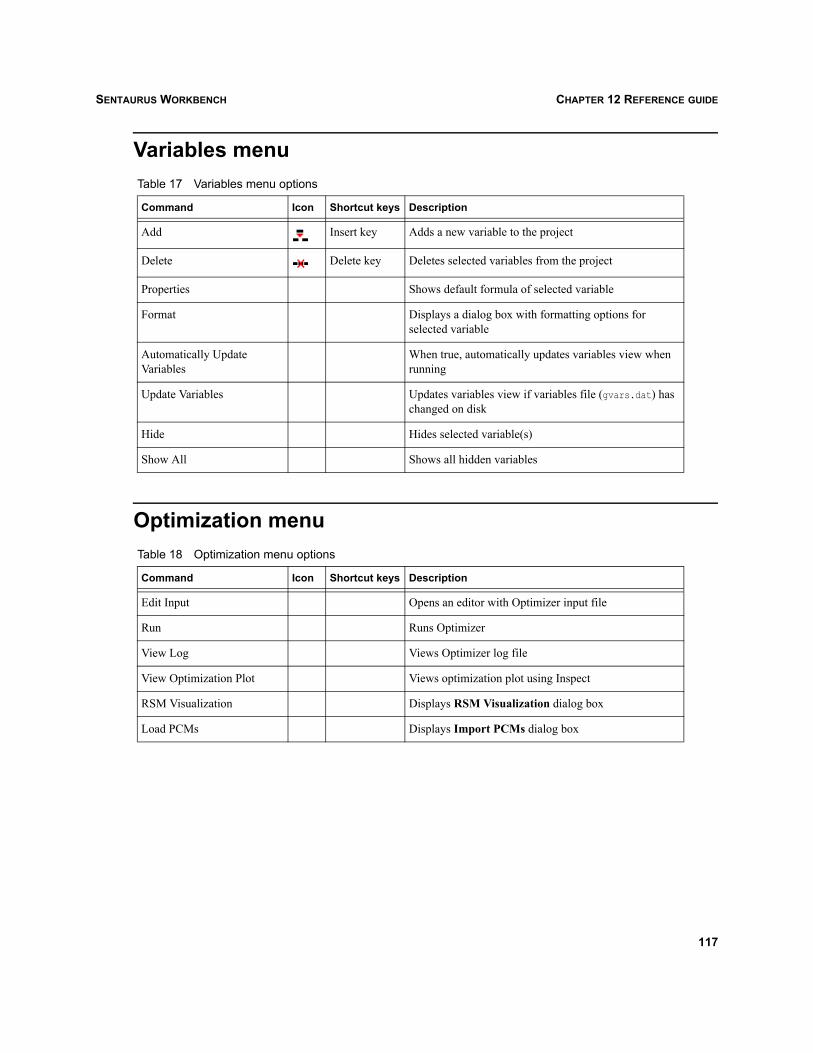
SENTAURUS WORKBENCH CHAPTER 12 REFERENCE GUIDE
Variables menu
Optimization menu
Table 17 Variables menu options
Command Icon Shortcut keys Description
Add Insert key Adds a new variable to the project
Delete Delete key Deletes selected variables from the project
Properties Shows default formula of selected variable
Format Displays a dialog box with formatting options for selected variable
Automatically Update Variables
When true, automatically updates variables view when running
Update Variables Updates variables view if variables file (gvars.dat) has changed on disk
Hide Hides selected variable(s)
Show All Shows all hidden variables
Table 18 Optimization menu options
Command Icon Shortcut keys Description
Edit Input Opens an editor with Optimizer input file
Run Runs Optimizer
View Log Views Optimizer log file
View Optimization Plot Views optimization plot using Inspect
RSM Visualization Displays RSM Visualization dialog box
Load PCMs Displays Import PCMs dialog box
117

SENTAURUS WORKBENCHCHAPTER 12 REFERENCE GUIDE
Calibration menu
Extensions menu
Help menu
Table 19 Calibration menu options
Command Icon Shortcut keys Description
Project Wizard See the Calibration Kit manual
Scenario Wizard See the Calibration Kit manual
Process Wizard See the Calibration Kit manual
Parameter Wizard See the Calibration Kit manual
Optimization Wizard See the Calibration Kit manual
Table 20 Extensions menu options
Command Icon Shortcut keys Description
New Script Creates and opens a new file for a Tcl script
Run Script Runs a Tcl script
Edit Script Edits a file containing a Tcl script
Run Dios Opens a new command prompt and runs Dios
Run Sentaurus Process Opens a new command prompt and runs Sentaurus Process
Run Inspect Opens a new command prompt and runs Inspect
Run Tecplot SV Opens a new command prompt and runs Tecplot SV
Run Merger Opens a new command prompt and runs Merger
Table 21 Help menu options
Command Icon Shortcut keys Description
About Ctrl+B Provides version information
Manuals Opens a front page to the technical documentation (PDF) in Acrobat Reader
Training Opens Sentaurus training material in a Web browser
118

SENTAURUS WORKBENCH CHAPTER 12 REFERENCE GUIDE
Keyboard navigation keys
Preprocessor and reference syntax
@-references and tree navigationThe syntax of @-references in EBNF notation is:
reference: simple_reference [ operator [ operator] ]
simple_reference: ("node" | "previous" | "tool" | file_type["/i"]|["/o"] | parameter_name |variable_name)
operator: (":"|"|") (["+"|"-"] number | tool_name | "first" | "last" | "index" | "all" |"min" | "max")
where:
file_type One of the file types defined in the tool database.
/i and /o Extensions to file_type refer to the corresponding input and output files of thecurrent tool. Without extensions, an implicit input file generated by a precedingtool is searched further up the tree.
parameter_name One of the declared parameters.
variable_name One of the known variables.
tool_name The name of a tool instance in the simulation flow; the corresponding tool isdefined in the tool database of Sentaurus Workbench.
The following relative direction suffixes can be used:
| A horizontal navigation operator.
: A vertical navigation operator.
+number A relative reference in right horizontal or downward vertical direction.
-number A relative reference in left horizontal or upward vertical direction.
number An absolute index reference in right horizontal or downward vertical direction.
Table 22 Keyboard navigation keys
Key Description
Tab Moves between the projects browser and project viewer panel
119
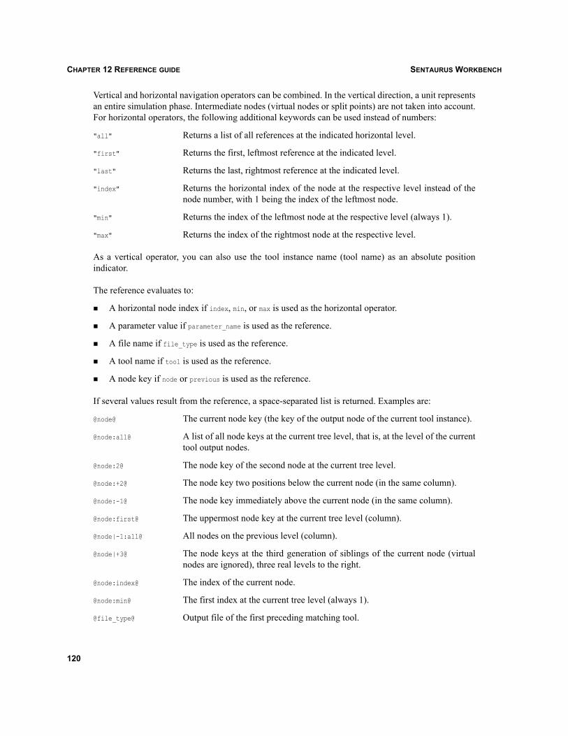
SENTAURUS WORKBENCHCHAPTER 12 REFERENCE GUIDE
Vertical and horizontal navigation operators can be combined. In the vertical direction, a unit representsan entire simulation phase. Intermediate nodes (virtual nodes or split points) are not taken into account.For horizontal operators, the following additional keywords can be used instead of numbers:
"all" Returns a list of all references at the indicated horizontal level.
"first" Returns the first, leftmost reference at the indicated level.
"last" Returns the last, rightmost reference at the indicated level.
"index" Returns the horizontal index of the node at the respective level instead of thenode number, with 1 being the index of the leftmost node.
"min" Returns the index of the leftmost node at the respective level (always 1).
"max" Returns the index of the rightmost node at the respective level.
As a vertical operator, you can also use the tool instance name (tool name) as an absolute positionindicator.
The reference evaluates to:
A horizontal node index if index, min, or max is used as the horizontal operator.
A parameter value if parameter_name is used as the reference.
A file name if file_type is used as the reference.
A tool name if tool is used as the reference.
A node key if node or previous is used as the reference.
If several values result from the reference, a space-separated list is returned. Examples are:
@node@ The current node key (the key of the output node of the current tool instance).
@node:all@ A list of all node keys at the current tree level, that is, at the level of the currenttool output nodes.
@node:2@ The node key of the second node at the current tree level.
@node:+2@ The node key two positions below the current node (in the same column).
@node:-1@ The node key immediately above the current node (in the same column).
@node:first@ The uppermost node key at the current tree level (column).
@node|-1:all@ All nodes on the previous level (column).
@node|+3@ The node keys at the third generation of siblings of the current node (virtualnodes are ignored), three real levels to the right.
@node:index@ The index of the current node.
@node:min@ The first index at the current tree level (always 1).
@file_type@ Output file of the first preceding matching tool.
120

SENTAURUS WORKBENCH CHAPTER 12 REFERENCE GUIDE
@file_type:all@ A list of all file names of type file_type produced by the tool at the current treelevel.
@file_type:3@ The file name of type file_type of the third tool instance at the current tree level.
@file_type:tool@ The file of type file_type at the level of tool.
@file_type:+1@ The file of type file_type at the node below the current node (in the samecolumn).
@file_type:last@ The rightmost file of type file_type at the current level.
@file_type/i@ Input file of type file_type of the current tool (by default tool_acronym.file_acronym, for example, des.grd).
@file_type/o@ Output file of type file_type of the current tool if defined as an output file.
@file_type/o|-1@ Output file of type file_type of the previous tool if defined as an output file.
@node:max@ The last index at the current tree level, the number of nodes at the current level.
@tool@ The name of the tool at the current node.
@tool|all@ A list of the sequence of tools appearing in the simulation flow.
@tool|1@ The first tool in the simulation flow, the tool at absolute level 1.
@tool|+1@ The name of the following tool.
@tool|-1@ The name of the previous tool.
@tool|first@ The first tool in the simulation flow.
@tool|last@ The last tool in the simulation flow.
An additional reference that returns the current directory can be used without suffixes only:
@pwd@ Absolute path of project.
@pwd@/@file_type@ File reference with absolute path.
#-commandsAny preprocessor command starts with an #-sign as the first character on a line. White space (space ortab characters) are allowed after the initial # for indentation. gpp recognizes the following commands:
#<string> This is a comment. gpp strips all comment lines from the preprocessed file andreplaces them with empty lines. <string> is any string not listed here as apreprocessor command.
#define <name> <string>
This defines the new macro <name>. gpp replaces subsequent instances of <name>with <string>.
121

SENTAURUS WORKBENCHCHAPTER 12 REFERENCE GUIDE
#setdep <list of nodes>
Explicitly sets dependencies of these nodes.
#remdep <list of nodes>
Explicitly removes dependencies from these nodes.
#include "<filename>" Includes the contents of file name at this point. gpp processes the included fileas if it were part of the current file.
#includeext "<filename>"
This is the same as the #input command, but with advanced processing of<filename>. It allows <filename> to contain macros already defined with the#define command.
#if <expression> Subsequent lines up to the matching #else, #elif, or #endif commands, appearin the output only if <expression> evaluates to nonzero. <expression> is anystandard Tcl expression that evaluates to a number. Before evaluation, all@-substitutions are expanded in <expression>.
#if in <gexpr> Same as the previous #if command, but evaluated to true when the current nodebelongs to the nodes returned by gexpr (see Node expressions on page 62).
#elif <expression> Any number of #elif commands may appear between an #if command and amatching #else or #endif command. If the expression evaluates to nonzero,subsequent #elif and #else commands are ignored up to the matching #endif.Any expression allowed in an #if command is allowed in an #elif command.The lines following the #elif command appear in the output only if all of thefollowing conditions are met:– The expression in the preceding #if command is evaluated to zero.– The expressions in all preceding #elif commands are evaluated to zero.– The current expression evaluates to nonzero.
#else Inverts the sense of the conditional command otherwise in effect. If thepreceding conditional indicates that lines are to be included, lines between the#else and the matching #endif are ignored. If the preceding conditional indicatesthat lines would be ignored, subsequent lines are included in the output.Conditional commands and corresponding #else commands can be nested.
#endif Ends an #if section.
#exit Stops preprocessing at this line; the following lines are stripped.
#verbatim <string> A line starting with #verbatim is not stripped, that is, the prefix #verbatim isremoved, but the rest of the line is not touched.
#rem <string> A line starting with #rem is not stripped, but @-substitutions are expanded in therest of the line.
#noexec Does not execute (submit to scheduler) the current node.
#set <varname> <value> Sets the value of <varname>.
122

SENTAURUS WORKBENCH CHAPTER 12 REFERENCE GUIDE
Split commandsThe following preprocessor commands handle split points:
#header Marks the first line of the header section. The header section is copied in thebeginning of each partial input file before the load command. Only one headercan be defined.
This command is mandatory for projects that are preprocessed using gpp. Withthe preprocessor spp, this command is supported but it can be omitted.
#endheader Last line of the header section, replaced by a blank line.
This command is mandatory for projects that are preprocessed using gpp. Withthe preprocessor spp, this command is supported but it can be omitted.
#postheader A postheader is an input file section that is copied after the load command ineach partial input file. This is useful to define simulator defaults, which must bereset after a load command. Any number of postheaders can be defined at anyposition in the original input file. They are appended after the load command inthe order of their definition. Nesting or overlapping postheaders are notallowed.
#endpostheader Last line of a postheader section, replaced by a blank line.
#split PNAME Defines a split on parameter PNAME. The input file is cut at this point into (1) apartial input file from the previous split point to the current line and (2) anotherpartial input file from the current line to the next split point (or to the end of thefile). The current line is replaced with a save command at the end of the firstpartial input file. The second partial input file starts with the header, followedby the simulator load command, the optional postheaders and, finally, the realpartial input section. param_name denotes the tree level where the split applies.
NOTE Multiple split points are valid only if they appear in the same order as the correspondingparameters in the simulation flow. If that is not the case, the preprocessor takes only the bestpossible match, ignoring certain split points.
NOTE A partial input file (corresponding to a split section) is considered a conventional tool inputfile regarding forward references. A common mistake is to introduce a split point after aparameter @-reference, when the referenced parameter appears after the split parameter inthe simulation flow.
123

SENTAURUS WORKBENCHCHAPTER 12 REFERENCE GUIDE
NOTE Every #-preprocessor command that is supposed to be unique (common) to all split files mustbe placed in the header section (#header ... #endheader). For example, the following threemacro definitions will appear in all files produced by #split:
#header
...
#define macro1 string1
#define macro2 string2
#define macro3 string3
...
#endheader
Otherwise, these macro definitions will be placed in the first file only and will be unknownto the other files that were created after splitting. It can result in a preprocessing error.
Node expressionsThe EBNF syntax of a node expression GEXPR is:
gexpr : gterm [operator gterm]operator : "+" | "*" | "-" | "^"gterm : scnr["|"level][":{" filter "}"] | tool[":{" filter "}"] | node | "(" gterm ")" | "~" gtermnode : integerscnr : "all" | identifierlevel : integer | "last" | tooltool : identifierfilter : tcl_expr
where:
scnr Name of a scenario
tool Name of a tool instance
node Node number
level Tree level, starting from 0
last Last tree level
"+" The ‘or’ or ‘union’ binary operator
"*" The ‘and’ or ‘intersection’ binary operator
"-" The ‘difference’ binary operator
"^" The ‘exclusive-or’ binary operator
"~" The ‘extend-to-root’ binary operator
filter Tcl expression
124

SENTAURUS WORKBENCH CHAPTER 12 REFERENCE GUIDE
Schedulers
Scheduling systemsParameter studies involving several parameters usually require a large number of simulation runs. Thelimited interdependency of the individual simulation steps makes this type of application an excellentcandidate for exploiting coarse grain parallelism on a network of workstations.
To take advantage of this situation, Sentaurus Workbench offers access to different, more or lesssophisticated, back end job scheduling systems. Access to these systems is transparent. However, theinstallation and initialization of a distributed scheduling system is usually a complicated task, as itrequires many conditions to be fulfilled in the network environment.
A distributed system is also much more difficult to troubleshoot than a conventional application. Thissection provides guidelines to set up, test, and successfully operate the scheduling facilities of SentaurusWorkbench, with a strong emphasis on the ‘in-house’ DMW system. Details of installing and runningthe Load Sharing Facility (LSF) system can be found in the appropriate vendor manuals.
Sentaurus Workbench provides a unified scheduling approach, by which users can submit jobs to anyscheduler or queue. Each node can be assigned to any queue defined by the systems administrator.
Sentaurus Workbench supports three back end execution engines:
Local Executes jobs sequentially on the local machine; does not require any specialsetup and does not produce any scheduling overhead. Useful for running shortsimulations, or setting up and debugging more complex projects.
DMW Load-sharing scheduler embedded into gsub, using a ‘centrally coordinated’scheduling approach. Useful for distributing the execution of large projects ona network of heterogeneous workstations.
LSF Load Sharing Facility is a widely used third-party load-sharing systemdeveloped by Platform Computing Inc. It offers a wide range of schedulingoptions and a complete set of administration tools; better suited for largecorporate networks.
The DMW and LSF systems work on a cluster of heterogeneous workstations sharing a common filenamespace. Therefore, the following conditions are mandatory for proper DMW and LSF exploitation:
Synopsys TCAD simulation software is installed on all of the workstations that will be used. STROOTis identical (same absolute path) on all workstations. The easiest way to obtain this is to share (NFSmount) the file system where the Synopsys software is installed.
The user project space is shared by all participating workstations and accessible through the sameabsolute path. Again, the easiest way to obtain this is to NFS mount the file system where the STDBof the user resides.
125

SENTAURUS WORKBENCHCHAPTER 12 REFERENCE GUIDE
A global queue definition file must be set up by the systems administrator, who provides the listcontaining queue names. For DMW, the systems administrator sets up a list of hosts (HostDB) that isavailable for that particular queue.
DMW1 SchedulerThe general goal of DMW is to distribute jobs over a cluster of network workstations to speed upsimulations and better exploit available computing resources, while avoiding the overloading ofindividual workstations and ensuring users have equal access opportunity to shared computingresources.
To achieve this goal, DMW uses a centrally coordinated scheduling approach. A global arbiter runs ona single host; this is the DMWUmpire daemon. The task of the arbiter is to globally allocate hosts toclients (gsub processes). On a client request, the DMWUmpire decides which is the best machinecurrently available for that client. If it finds a suitable host, it allocates it to the client and keeps thecorresponding resource busy until the client explicitly releases it (when the job is completed).
To obtain an overview of the current activity on the workstations, the DMWUmpire requires local stateinformation from each host. It evaluates the state of a machine using three indicators:
Current ‘load average’ (the average number of jobs in the run queue over the last minute; see alsothe UNIX uptime command)
Free physical memory
Number of processors
A daemon running on each host, the DMWMole, captures local state information and sends it to theDMWUmpire upon request.
Actual job execution is initiated by the gsub program. For each ‘ready-to-run’ job, gsub asks the globalDMWUmpire for a host and then dispatches the job by using a job-monitoring daemon, theDMWLaunchPad. The job-monitoring daemon runs together with its job on the target machine andreports the state of its protégé to the gsub instance that initiated the execution.
After installation of the Synopsys software, the systems administrator needs to configure the DMWsystem for the particular computing environment. The following files store the initial DMWconfiguration information:
Host database Describes the computing environment, that is, which workstations are availableand their relative powers.
Constraint database Describes job-to-host constraints, that is, which types of job are susceptible torun on which hosts.
1. The acronym DMW stands for ‘the Devil Makes Work for idle hands.’
126

SENTAURUS WORKBENCH CHAPTER 12 REFERENCE GUIDE
Host database
The DMW host database enumerates the workstations eligible for hosting jobs. All of the listed hostsmust be interconnected at the TCP level to be able to communicate using sockets (they need notnecessarily belong to the same physical network), they must trust each other in the sense of the rshprotocol, and they must share a common file namespace. A global database is stored in a simple text filecalled HostDB and located in the directory $STROOT/tcad/$STRELEASE/lib/glib, or alternatively, $STROOT/tcad/$STRELEASE/lib.
The format of the HostDB file is that lines starting with a # character are considered comments and areignored. All other lines should contain the following fields separated by spaces:
1. Name of workstation (host name) or host IP address.
2. Hardware architecture of host (refer to the Installation Guide).
3. Operating system of host (refer to the Installation Guide).
4. A positive real number greater than zero as an indicator of the performance index of the workstation.The default value is 1.0. Practical values should be 0.8 or greater.
5. Optionally, an integer as the maximum number of simultaneous jobs the workstation can accept. Thedefault value is 1.
An exclamation point (!) preceding a host definition indicates that the corresponding host is temporarilydisabled (no jobs will be dispatched to it).
Fields 2 and 3 are purely informative; they are not used by the scheduler.
Value 4 is an indicator of the comparative ‘quality’ of the workstations and has a proportional weight inthe host allocation policy of the DMWUmpire. Value 4 should reflect the overall machine performancein terms of processor speed and amount of memory, but should not consider the number of processors(the number of processors is already taken into account in the host allocation policy). Hosts with a highperformance index tend to receive jobs before less powerful hosts and, as a consequence, are more busy.
NOTE The performance index has strictly no influence on the type of job a host will receive (it is notthat a host with a high performance index will have ‘memory-gluttonous’ jobs and so on).
Value 5 indicates the maximum number of jobs the host will accept. This value should usually match thenumber of processors. In typical conditions, it is a waste of resources to run jobs in time-sharing mode.However, for special jobs, such as interactive jobs or jobs performing a lot of output, it may beadvantageous to set a value higher than the number of processors.
NOTE Value 5 is authoritative: no more jobs are dispatched to a host already running its maximumnumber of jobs.
127

SENTAURUS WORKBENCHCHAPTER 12 REFERENCE GUIDE
Furthermore, the first host in the HostDB file (regardless of whether this host is enabled) is used to specifythe arbitration host (the host where DMWUmpire will run). Ensure that this host is a reliable machinein your network. A simple and good solution is to specify the host that is running the license daemon asthe global arbitration host.
An example of a host database is:
## Example host database#speedy sun4u Solaris8 1woody ix86 Linux 1turtle sun4u Solaris8 2! rabbit ix86 Linux 2
In this example, woody and rabbit are Linux machines, while speedy and turtle are ones with the Sunplatform. turtle and rabbit are equipped with two processors; rabbit is disabled.
The global HostDB file must be created at installation time and should be maintained by the systemsadministrator.
Constraint database/queues
Based on the global, user, and project definitions, the constraint database is created as a temporary fileat run-time. DMW scans the constraint database to determine the suitable hosts for a job running the tooltool and queued into the queue queue.
In Sentaurus Workbench, the queue definition file encompasses all of ConstraintDB, therefore, creationand maintenance of ConstraintDB is performed internally. To modify ConstraintDB, users can set up theirhosts in their user queue definition file.
Host allocation policy
The role of the DMWUmpire daemon is to globally allocate hosts to gsub clients. DMWUmpiremaintains a list of eligible hosts under its control and monitors their state. A host can be:
dysfunctional Unreachable; DMWMole does not respond.
embargoed Excluded for 90 seconds after being allocated, to stabilize the ‘load average.’
overworked The maximum number of jobs of the host has been reached.
intolerable When Load / PEs 0.9 or FreeMem 20000 KB.
available When none of the previous conditions apply.
≥ ≤
128

SENTAURUS WORKBENCH CHAPTER 12 REFERENCE GUIDE
where:
Load is the UNIX standard ‘1 min load average’, that is, the average number of jobs in the run queueover the last minute.
PEs is the number of processors.
FreeMem is the amount of free physical memory in kilobyte.
DMWUmpire allocates only available hosts and uses a ‘best-first’ allocation policy. Hosts are sorted bytheir score, a weighted assessment of their load average:
score = 100 * PerfIndex / ((Load / PEs) + 1.0)
where PerfIndex is the most recent performance index announced for that host.
DMWUmpire satisfies the next request of the client by granting the available host with the highest score.If there is no available host, the request is denied and the client waits until a host is available.
Troubleshooting DMW
The DMW system automatically starts daemons (DMWUmpire, DMWMole, and DMWLaunchPad)when and where it is necessary; no explicit user intervention is required. DMW starts daemons and jobsusing the remote shell protocol (rsh or remsh on HP-UX machines). In order for rsh and DMW to work,the following two conditions must be satisfied:
The workstations should mutually trust each other, that is, rsh (remsh on HP-UX machines) can beused to launch a job from or to any participating workstation.
User log-in sessions must be silent (no message is printed by the log-in script).
To check these conditions, the following command should succeed for any user from all to allworkstations:
Input: % rsh <hostname> echo coucou
Output: coucou
The login is silent if nothing other than coucou is printed.
The DMWMole daemon monitors the load average, free memory, and number of processors of the hoston which it is running. To check the current values on the local host, type the command:
Input: % DMWMole -test
Output: Load averages: 1.20,1.70,2.28 Memory: 1703936K real,70440K free
NOTE This command does not start the daemon and it does not interfere with a daemon running inthe background.
129

SENTAURUS WORKBENCHCHAPTER 12 REFERENCE GUIDE
The DMWTest utility makes it possible to exercise the DMW daemons and to highlight connectivity orcommunication problems. DMWTest uses the same protocol as the DMW system to start the daemonsin the background, to connect to the daemons, to send requests, and to receive responses. For example,to check the DMW daemons on all the hosts listed in the global host database, type the command:
DMWTest
If everything is satisfactory, the output is similar to:
Loading host database '/remote/tcadprod/tcad/12.0/L1/lib/HostDB'Checking DMWUmpire@speedy [170.1.1.72]
connecting..................... -> OK (DMWUmpire version [20050901])Checking DMWMole@woody [170.1.1.178]
connecting......... -> OK (DMWMole version [20050901])getting machine info.. -> R 0.04 798024 1
Checking DMWMole@turtle [170.1.1.112]connecting......... -> OK (DMWMole version [20050901])getting machine info.. -> R 0.02 890024 2
...
To check the connection from the local host to a DMWMole on a specific host, use the command:
DMWTest <hostname>
DMWTest can also be used to shut down already running daemons. For example, the command:
DMWTest -s <hostname>
performs the same test as the previous command, but shuts down the daemon afterwards.
NOTE Shutting down daemons is especially necessary before an upgrade of the DMW softwarecomponents.
LSF SchedulerAs an alternative to the DMW scheduling system, Sentaurus Workbench provides an interface to theLoad Sharing Facility (LSF) system. LSF integrates a cluster of heterogeneous workstations into a singlesystem environment and provides sophisticated job scheduling policies. It can be used to submit anddistribute project simulation jobs over the local network. As with DMW, LSF queues can be accessedthrough the Scheduler window.
To use LSF, the following conditions must be fulfilled:
1. The local host (the one running Sentaurus Workbench and gsub) is a LSF client or server.
2. On the local host, the LSF binaries are accessible through the variable PATH (add $LSF/bin to yourPATH variable before starting Sentaurus Workbench).
130

SENTAURUS WORKBENCH CHAPTER 12 REFERENCE GUIDE
3. Synopsys TCAD simulation software is accessible to all LSF server workstations.
4. The project space is accessible to all LSF servers with the same absolute path.
To check points 1 and 2, the following two commands should succeed on the local host:
% lsidLSF 5.0, May 31 2002Copyright 1992-2002 Platform Computing CorporationMy cluster name is test_clusterMy master name is <local hostname>
% bqueuesQUEUE_NAME PRIO STATUS MAX JL/U JL/P...big_jobs 1 Open:Active - 2 2......
gsub uses the bsub command to submit jobs to LSF and the bjobs command to track job status. Users canspecify additional bsub command-line options using the queue options (see Configuring the schedulingsystem on page 131). To execute each node, gsub does not directly submit the corresponding toolcommand line, but launches a job wrapper, the gjob utility. The latter updates the job status and locallyexecutes the prologue tool and epilogue of the corresponding tool as defined in the tool database.
The DMW host database has no effect on LSF. Refer to the appropriate LSF manuals to obtain similarconfigurations.
NOTE Tool database settings control which bsub and bjobs will be executed. The correspondingsettings are WB_binaries(tool,bsub) and WB_binaries(tool,bjobs).
Configuring the scheduling systemThe scheduling system requires a global queue configuration file and HostDB to function properly. Thesetwo files must be set up by the systems administrator. To set up these files, the following information isrequired:
List of computing machines available in the network
Details of machines such as number of processors
In addition to the queue configuration, tools must be properly associated with the queues in thescheduling systems.
Global queue configuration file
A queue configuration file (gqueues.dat) consists of definitions of all the scheduling systems availableto users. It consists of the name of the back end scheduler and a unique name for each queue.
131

SENTAURUS WORKBENCHCHAPTER 12 REFERENCE GUIDE
The queue configuration file is located at $STROOT/tcad/$STRELEASE/lib/glib or $STROOT/tcad/$STRELEASE/lib. The queue definitions in the file are used by the front ends of Sentaurus Workbench and thecommand-line job submission utilities.
An example of a queue definition file is:
#local queue nice levelqueue local:default "19" queue local:priority "10"
#dmw queues hostsqueue dmw:long "sun101 sun102 sun104"queue dmw:hpux11 "hp101"#lsf queues bsub stringqueue lsf:default "bsub"queue lsf:short "bsub"
The scheduling system of Sentaurus Workbench supports three different schedulers, which can be usedsimultaneously.
For local queues
The queue configuration for local queues (that is, for jobs that are run on the local machine) is set up asfollows:
queue local:<queue_name> <desired nice level>
For example, a priority queue can have a lower nice level:
queue local:priority "10"
For LSF queues
For installing and setting up LSF queues, refer to the LSF Installation Manual.
From the Sentaurus Workbench side, in the global queue configuration, the systems administrator mustlist all LSF queues that users can access. The systems administrator also must set up the resource strings,specifying applicable resource restrictions.
The format of the LSF queue specification string for the global queue configuration file is:
queue lsf:<lsf_queue_name> <bsub constraint_options>
where lsf_queue_name is the name of the corresponding LSF queue and constraint_options containsarbitrary constraint specifications.
For example, a queue <mylsfqueue> with additional resource constraints can be defined for SentaurusWorkbench as:
queue lsf:mylsfqueue "bsub -R \"linux && mem>1000\""
132

SENTAURUS WORKBENCH CHAPTER 12 REFERENCE GUIDE
When Sentaurus Workbench runs a job using this queue, the following command will be generated onthe basis of the queue definition:
bsub -R "linux && mem>1000" -o <log_file> -q mylsfqueue -P <project_id> -J <job_name> \<gjobs command string>
NOTE Using the backslash (\) in the specification of an LSF resource string to protect doublequotation marks is mandatory; otherwise, Sentaurus Workbench removes double quotationmarks during Tcl evaluation and the LSF bsub command fails on the wrong syntax.
The name of a real LSF queue and the name of the corresponding queue in the global queueconfiguration file of Sentaurus Workbench usually are the same, but it is not obligatory. SentaurusWorkbench allows users to create so-called queue aliases, where Sentaurus Workbench queues havedifferent names and resource strings, and refer to the same LSF queue. For example:
queue lsf:refqueue1 "bsub -R \"swp > 5 && mem > 10\" -q normal"
queue lsf:refqueue2 "bsub -R \"swp > 10 && mem > 20\" -q normal"
queue lsf:refqueue3 "bsub -R \"swp > 15 && mem > 30\" -q normal"
These three Sentaurus Workbench queues refqueue1, refqueue2, and refqueue3 are not real LSF queues,that is, they do not exist in the LSF environment. In fact, these queues refer to the same LSF normalqueue. The LSF bsub command supports multiple -q command-line options, but the last one specifies theLSF queue for the execution. That is why, in the example above, simulations scheduled among threequeues will be submitted to the same LSF queue normal, but with different resource restrictions.
When the lsf:default queue for LSF is specified in the global queue configuration file, SentaurusWorkbench expects explicit specification of the LSF queue in the constraint options, for example:
queue lsf:default "bsub -R \"linux && mem>1000\" -q mylsfqueue"
For additional bsub options, refer to the LSF Manual.
For DMW queues
Setting up DMW queues requires more effort compared to local and LSF queues. All availablecomputing hosts must be grouped in a logical manner and each group must be assigned a group name.Then, each group must be added to the queue configuration file as follows:
queue dmw:<queue_name> "<list of hosts>"
For example, a company with hosts "hp1 hp2, sun1 sun2 sun3, linux1 linux2 linux3" can have three DMWgroups, such as hp_queue, sun_queue, and linux_queue.
The configuration can now be set up as:
queue dmw:hp_queue "hp1 hp2"queue dmw:sun_queue "sun1 sun2 sun3" queue dmw:linux_queue "linux1 linux2 linux3"
133
SENTAURUS WORKBENCHCHAPTER 12 REFERENCE GUIDE
HostDB (for DMW)
All hosts that are listed in the DMW queues must be put in the HostDB setup by the systems administrator.For setting up the HostDB, see Host database on page 127.
Tool associations
Sentaurus Workbench supports four levels of tool-queue associations: global, user, project, and node.The systems administrator sets up the global tool-queue association. Users can configure the other threelevels to meet their requirements.
It is not possible to use the queue keyword in the user-project queues files. This means it is not possibleto set up new queues on the user and project levels. These levels have permission to assign the tools andthe nodes to specific queues.
Global, user, and project tool-queue associations have a specific format:
tool <tool_name> "options" <scheduler:queue_name>
For example:
tool dios "" dmw:long
defines the running of all nodes associated with the tool dios on the hosts specified by the queue dmw:long.
Another example is:
tool dios "sun101 suns102" dmw:long
which defines the running of all nodes associated with the tool dios on the hosts sun101 or sun102. This isthe way to reduce the globally specified queue on the user or project level. The specified list of hostsshould be a subset of the main host list, which is specified for the queue on the global level.
The keyword default can be used to specify all tools, that is, the assignment:
tool default "hp1 hp2 sun101 sun102" dmw:long
means that all tools will run in the dmw:long queue with the subset of hosts provided in the options field.
The options are specific to the scheduler used and differ accordingly, and are explained in Global queueconfiguration file on page 131.
NOTE Of the following options, the user tool associations and project tool associations can bemodified from the Scheduler GUI. The node-specific constraints can be edited manually fromthe Scheduler GUI or by using a text editor (see Configuring project queues on page 24).
134

SENTAURUS WORKBENCH CHAPTER 12 REFERENCE GUIDE
Global tool associations
Global tool associations are written to the global queue configuration file and are loaded with the setup.These associations apply to all users.
User tool associations
Users can use the list of queues and prepare the assignment of tools to queues. The options can bemodified according to the requirements. The user tool associations are stored in the filegqueues_<username>.dat in the $STDB directory of the user. All the definitions specified complement andoverride any definitions at the global level and apply to all projects of the user.
Project tool associations
Users can configure the tool queue associations at the project level. These definitions are stored in thegqueues.dat file in the project directory.
All definitions override any setting at the global level or user level, and apply to the current project only.
For Local Scheduler The option field represents the nice level at which the tool needs to be run.
For LSF Scheduler The option re-defines the resource string.
For DMW Scheduler The option is the subset of the hosts, belonging to the particular DMW queue.
Node-specific constraints
Node-specific constraints are handled by expanding the expression and applying the constraints to thenodes that match the expression. Node level constraints are applied during run-time:
node "gexpr" <queue:name> "options"
For example:
node "all:{ @P1@ > 2.0 }" local:default "11"
Node-specific constraints can be set up at global, user, or project level. These settings are stored in therespective definition files as previously mentioned.
NOTE The definitions are cascaded with the latest setting overwriting the setting of the previouslevel, that is, the global queue file is loaded initially, and the global tool-queue associationsand their corresponding strings are loaded. Then, the user-queue definition file is loaded. Anyprevious definition related to a particular tool is overwritten. Similarly, the project queuedefinition overwrites the user definitions.
NOTE Users cannot set up new queues. However, tool queue assignments can be overwritten.
135

SENTAURUS WORKBENCHCHAPTER 12 REFERENCE GUIDE
Run-time assignments in the GUI
A finer control is available to the user at project run-time. Just before the user commits a project to run,the queue definitions are loaded and the nodes are assigned as per the queue tool definitions.
However, the user can manually alter the assignment of nodes to any queue. A simple cut-and-pasteinterface is available (see Figure 49 on page 82).
Sentaurus Workbench files
Project filesThe project files that are specific to Sentaurus Workbench are:
gtree.dat Contains the simulation tree.
gvars.dat Contains all variables of a project.
gtooldb.tcl The tool database of a project.
glog.txt Contains the project log data.
greadme.txt The readme file of a project.
greadme.pdf The documentation file of a project.
preprocessor.log Contains preprocessor log data.
gexec.cmd Jobs execution graph.
gcmds.dat Intermediate file consisting of new jobs to the scheduling system.
gopt.cmd Optimizer input file.
gopt.log Optimizer log file.
gqueues.dat Queues configuration file.
gsummary.txt Summary of a project.
The following files are hidden files, which are not necessarily visible in the directory listings of theproject:
.project An empty file indicating that the current directory is a project directory.
.status Project status.
.history The events history of a project (including preprocessing, runs, cleanup, and soon).
136

SENTAURUS WORKBENCH CHAPTER 12 REFERENCE GUIDE
.gindex Snapshot of current node status (usually for a running project).
.gview Project columns configuration file.
User configuration filesAll these files are in the env(STDB) directory:
gqueues_<user>.dat Queues configuration file.
tooldb_<user> The tool database of the user.
Global configuration filesThese files are in the following directories:
$STROOT/tcad/$STRELEASE/lib/glib:
HostDB Host definition file for DMW (non-Windows versions only).
gqueues.dat Queues configuration file.
$STROOT/tcad/$STRELEASE/lib:
tooldb.tcl Global tool database.
Typical input and output filesThese are some typical file patterns seen in projects. The actual file names depend on the definitions ofthe tool database:
<tool_name>_<tool_acronym>.cmd Input file template: the command file of a tool.
<tool_name>_lig.cmd Ligament command file.
<tool_name>_<tool_acronym>.* The other input files of a tool that are configurable in the tool database.
pp<node_number>_<tool_acronym>.* Node input files created by preprocessing.
n<node_number>_<tool_acronym>.* Node output files.
137

SENTAURUS WORKBENCHCHAPTER 12 REFERENCE GUIDE
138
SENTAURUS WORKBENCH APPENDIX A DMW SCHEDULER: FREQUENTLY ASKED QUESTIONS
Sentaurus Workbench
APPENDIX A DMW Scheduler: Frequently asked questions
This appendix presents frequently asked questions regarding the DMW Scheduler.
Limitations of Sentaurus WorkbenchSentaurus Workbench does not permit the use of USER_HOSTDB. This is primarily a security feature.Previous versions of Sentaurus Workbench permitted users to use the hosts in their host database (HostDB)indiscriminately and to define queues, which are not defined globally. Only systems administrators canmodify the computation hosts, that is, add or remove hosts from running jobs.
Requirements for using DMW in a networkThe following requirements must be met to use DMW in a network environment:
On UNIX, DMW works on several UNIX flavors. (Windows systems are not supported.)
Shared file system: DMW requires the Network File System (NFS). All the directories are expectedto be the same throughout the network. DMW does not copy files across the network.
The following environment variables are exported by DMW across the job execution machine,while executing the jobs:
STROOTSTRELEASESTROOT_LIBSTDBDATEXLM_LICENSE_FILE
The time on the different network computers must be synchronized because Sentaurus Workbenchuses file creation times for updating the project status. Although Sentaurus Workbench cancompensate for some variation, different times on the machines can lead to problems with thescheduling process.
139

SENTAURUS WORKBENCHAPPENDIX A DMW SCHEDULER: FREQUENTLY ASKED QUESTIONS
Global queue and global host database filesThe global queue is the gqueues.dat file, which must be set up by the systems administrator. Thegqueues.dat file is read from either STROOT/tcad/STRELEASE/lib/glib or STROOT/tcad/STRELEASE/lib/.
The HostDB is the file that contains the list of computational hosts. The HostDB file is read from eitherSTROOT/tcad/STRELEASE/lib/glib or STROOT/tcad/STRELEASE/lib/. The HostDB setup is similar to earlierversions of Sentaurus Workbench.
The gqueues.dat file specifies the queue arrangements and queue configurations. The HostDB specifies theresource index and the number of jobs for hosts. The resource constraints of the hosts specified in thegqueues.dat file are specified in the HostDB.
Essentially, gqueues.dat is a file of Sentaurus Workbench whereas the HostDB file is read by DMW at run-time.
NOTE Since several versions of glib are possible, to avoid multiple copying, it is recommended toput the gqueues.dat and HostDB files in STROOT/tcad/STRELEASE/lib.
Administrator: Setting up DMW queuesThe systems administrator sets up the DMW queues in the following way:
1. Collect all computational hosts, for example, hp1, hp2, redhat1, redhat2, sun1, sun2.
2. Collect information about the hosts, such as the number of jobs that the host can run andperformance index.
3. Load the information about the hosts into the HostDB file.
4. Sort the hosts based on requirements. For example, the collection of hosts can be sorted based onplatform such as:
queue dmw:hp "hp1 hp2"queue dmw:sun "sun1 sun2"queue dmw:linux "redhat1 redhat2"
5. Write the information to the gqueues.dat file.
NOTE It is recommended that the systems administrator sets up a queue called dmw:all, whichincludes all hosts in the HostDB.
140

SENTAURUS WORKBENCH APPENDIX A DMW SCHEDULER: FREQUENTLY ASKED QUESTIONS
NOTE A host can be specified in as many queues as required. The hosts used under the gqueues.datfile must match the HostDB and vice versa.
User: Setting up user queues and project queuesThe user queue definitions file is located at STDB/gqueues_username.dat and the project queue definitionsfile is located inside the project directory as gqueues.dat.
The user cannot use the queue keyword in the user queue and project queue files. This means that the usercannot set up the queues. The user has permission to assign the tools to specific queues.
To assign a specific tool to a particular queue, type:
tool dios "" dmw:normal
The above definition will run all nodes associated with the tool Dios on the hosts specified by the queuedmw:normal.
The keyword default can be used to specify all the tools, that is, the assignment:
tool default "hp1 hp2 sun1 sun2" dmw:all
means all tools will be run in the dmw:all queue with the subset of hosts provided in the options field.
NOTE Always include the following header in the queue configuration files: isequeues: <identifier string>
User: Excluding a specific host and running on a specific set of hosts
The option string is the location to add or remove hosts from a specific queue. For example, assume thefollowing lines are in the global queue file:
isequeues: generic queuesqueue dmw:normal "hp1 hp2 sun1 sun2"queue dmw:linux "redhat1 redhat2"queue dmw:all "hp1 hp2 sun1 sun2 redhat1 redhat2"
141

SENTAURUS WORKBENCHAPPENDIX A DMW SCHEDULER: FREQUENTLY ASKED QUESTIONS
If the user needs to remove the host hp1 from the dmw:normal queue for all their projects, the user candefine this in the user queue file as:
tool default "hp2 sun1 sun2" dmw:normal
This excludes the host hp1 from execution and also restricts the host list to a specific subset of hosts.
Checking the DMWUmpireFirst, check the HostDB, which is located at STROOT/tcad/STRELEASE/lib/ or STROOT/tcad/STRELEASE/lib/glib.The master controller – DMWUmpire – is started in the first host in the HostDB.
To check the DMWUmpire, it is first necessary to establish a connection. For example, assume the firsthost in the HostDB is sun101.
To connect to the DMWUmpire, secure the credentials of the DMWUmpire:
1. Execute the command:
% rsh sun101 DMWUmpireM [xxx] A B
The reply indicates the M [Protocol Number] port_number cookie.
2. Connect to the DMWUmpire, using:
% telnet sun101 A
where A is the port number returned in the previous command.
3. Type:
E B [B is the second number, with cookie]M [xxxxx] F G
When a response is obtained, a connection to the DMWUmpire has been established.
4. The above commands can now be typed at the Telnet connection and responses can be obtained. Forexample, typing D will list the available hosts and the current status of the host. Typing S will shutdown the DMWUmpire.
The following commands and responses are possible with DMWUmpire:
Queries:
'E' cookie nl -- Establish credentials (must be first request)'J' jobs nl -- Confess to prior jobs'N' nl -- No Op, just confirm (with 'O')'H' IP/name [weight [#]]nl-- Host declaration (Reply 'D'/'I')'D' nl -- Dump list of hosts'C' nl -- Dump list of clients'T' nl -- Toggle logging'I' 0101010101... nl -- Interesting hosts'W' nl -- Want a host (Reply 'G'/'D')
142
SENTAURUS WORKBENCH APPENDIX A DMW SCHEDULER: FREQUENTLY ASKED QUESTIONS
'R' ID nl -- Release host (Reply 'D'/'O')'S' nl -- Shut down umpire'L' nl -- Load Limit on the Umpire (default is 0.9)'Q' nl -- Quit
Replies:
'M' protocol port cookie nl -- Protocol version, Master port & random password cookie'O' nl -- Still alive'I' ID nl -- Host ID'G' ID nl -- Grant host for launching a process'D' nl -- Denied request'H' nl -- Hasta la vista -- connection closed
Standard tests to troubleshoot a particular machine in the DMW network
Assume that machine A does not work on the DMW network. To troubleshoot this problem, thefollowing tests must be performed on machine A:
1. Ensure that rsh A works without asking for a password.
2. Ensure rsh is silent, for example:
% rsh A echo coucoucoucou
3. Run DMWTest:
% DMWTest AChecking DMWMole@A [XX.XX.XX.XXX]connecting..... -> OK (DMWMole version [_number_])getting machine info.. -> R 2.38 32864 2OVERWORKED: load average > 0.9 per processor
4. Run the DMWMole test:
% rsh A DMWMole -testLoad averages: 2.42, 2.37, 2.42 Memory: 2097152K real, 31456K free
5. Log on to the first host in the HostDB file.This is where the DMWUmpire resides.
6. From this machine, repeat Steps 1–4.
If the problem is not obvious at this stage:
1. Modify the HostDB file and replace the first host name with machine A.
2. Start a job and view the log.
If the problem persists, log on to the DMWUmpire and shut it down (see Checking the DMWUmpire onpage 142).
143

SENTAURUS WORKBENCHAPPENDIX A DMW SCHEDULER: FREQUENTLY ASKED QUESTIONS
Using ssh and DMW Scheduler togetherIt is generally advisable not use to systems other than rsh for a successful operation of DMW. In caseswhere ssh is the only means of communication, the following procedure must be adhered to:
ssh must be silent and no password must be requested, that is:
% ssh A echo testtest
DMW does not work across domains even with ssh.
If the above conditions are met, in addition to the requirements previously mentioned, to use ssh, setup the following environment variable to point to the location of ssh:
DMW_RSH_PATH = /my_path/ssh
NOTE /my_path/ssh must be the same in all machines; otherwise, the log-on scripts must beconfigured appropriately to reflect the changes.
NOTE It is not always guaranteed that ssh will work efficiently because of inherent differencesbetween rsh and ssh.
144