synchro-cyclotron - cern document server 1. foreword ... shielding walls and magnet foundation), and...
TRANSCRIPT
SYNCHRO-CYCLOTRON
1. Foreword
During 1955 the work of the Division consisted mainly in finally settling the design of the 600 Me V Synchro-cyclotron, working out detailed drawings for a number of its components, preparing specifications and placing contracts for the most important items to be manufactured by outside suppliers, and preparing for and starting construction on the site.
The greater part of the building programme was carried out according to schedule; and by the end of the year the most important sections of the outdoor work had been finished.
The task of organising the future experimental programme was also begun, and in this connection several meetings were held with a view to forming a team of physicists to work with the accelerator. During the year the staff of the Synchro-cyclotron Division increased from 12 to 32 persons; and regular meetings with the nine consultants of the Division were held in Geneva. It is estimated that the staff will be further increased during 1956.
No major delay has so far occurred in the machine programme, and work is proceeding in accordance with the schedules laid down in 1953 and 1954.
2. Building
As most of the excavation had been completed during the second half of 1954, the programme for 1955 began with the laying of the foundations. Reinforcing steel bars were laid and concrete cast for the foundations of the two experimental rooms, the central Synchro-cyclotron hall (including shielding walls and magnet foundation), and the auxiliary equipment room.
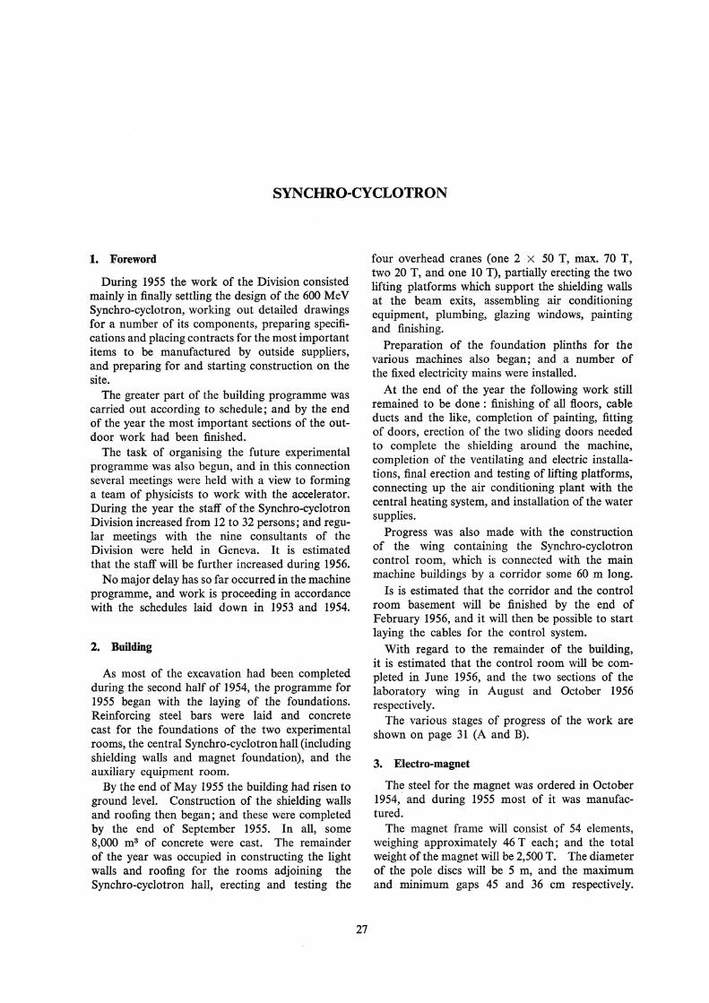
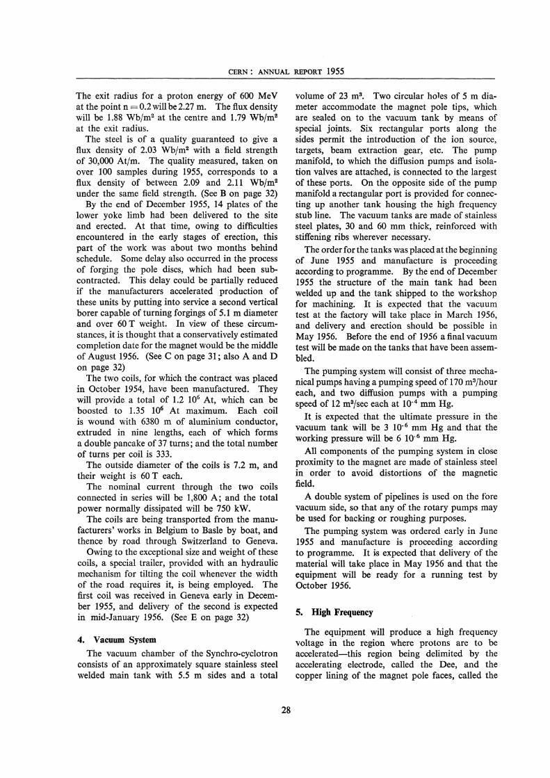
By the end of May 1955 the building had risen to ground level. Construction of the shielding walls and roofing then began; and these were completed by the end of September 1955. In all, some 8,000 m3 of concrete were cast. The remainder of the year was occupied in constructing the light walls and roofing for the rooms adjoining the Synchro-cyclotron hall, erecting and testing the
27
four overhead cranes (one 2 x 50 T, max. 70 T, two 20 T, and one 10 T), partially erecting the two lifting platforms which support the shielding walls at the beam exits, assembling air conditioning equipment, plumbing, glazing windows, painting and finishing.
Preparation of the foundation plinths for the various machines also began; and a number of the fixed electricity mains were installed.
At the end of the year the following work still remained to be done : finishing of all floors, cable ducts and the like, completion of painting, fitting of doors, erection of the two sliding doors needed to complete the shielding around the machine, completion of the ventilating and electric installations, final erection and testing of lifting platforms, connecting up the air conditioning plant with the central heating system, and installation of the water supplies.
Progress was also made with the construction of the wing containing the Synchro-cyclotron control room, which is connected with the main machine buildings by a corridor some 60 m long.
Is is estimated that the corridor and the control room basement will be finished by the end of February 1956, and it will then be possible to start laying the cables for the control system.
With regard to the remainder of the building, it is estimated that the control room will be completed in June 1956, and the two sections of the laboratory wing in August and October 1956 respectively.
The various stages of progress of the work are shown on page 31 (A and B).
3. Electro-magnet
The steel for the magnet was ordered in October 1954, and during 1955 most of it was manufactured.
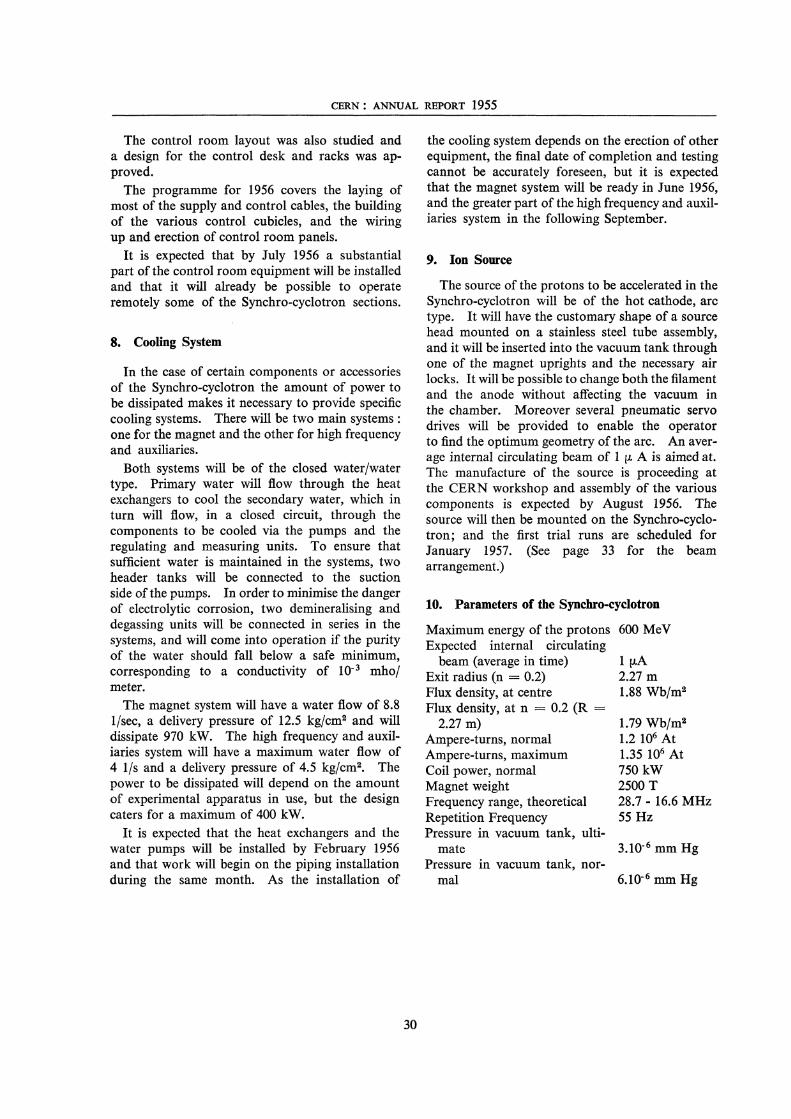
The magnet frame will consist of 54 elements, weighing approximately 46 T each; and the total weight of the magnet will be 2,500 T. The diameter of the pole discs will be 5 m, and the maximum and minimum gaps 45 and 36 cm respectively.
CERN : ANNUAL REPORT 1955
The exit radius for a proton energy of 600 Me V at the point n = 0.2 will be 2.27 m. The flux density will be 1.88 Wb/m2 at the centre and 1.79 Wb/m2
at the exit radius. The steel is of a quality guaranteed to give a
flux density of 2.03 Wb/m2 with a field strength of 30,000 At/m. The quality measured, taken on over 100 samples during 1955, corresponds to a flux density of between 2.09 and 2.11 Wb/m2
under the same field strength. (See B on page 32) By the end of December 1955, 14 plates of the
lower yoke limb had been delivered to the site and erected. At that time, owing to difficulties encountered in the early stages of erection, this part of the work was about two months behind schedule. Some delay also occurred in the process of forging the pole discs, which had been subcontracted. This delay could be partially reduced if the manufacturers accelerated production of these units by putting into service a second vertical borer capable of turning forgings of 5.1 m diameter and over 60 T weight. In view of these circumstances, it is thought that a conservatively estimated completion date for the magnet would be the middle of August 1956. (See Con page 31; also A and D on page 32)
The two coils, for which the contract was placed in October 1954, have been manufactured. They will provide a total of 1.2 106 At, which can be boosted to 1.35 106 At maximum. Each coil is wound with 6380 m of aluminium conductor, extruded in nine lengths, each of which forms a double pancake of 37 turns; and the total number of turns per coil is 333.
The outside diameter of the coils is 7.2 m, and their weight is 60 T each.
The nominal current through the two coils connected in series will be 1,800 A; and the total power normally dissipated will be 750 kW.
The coils are being transported from the manufacturers' works in Belgium to Basle by boat, and thence by road through Switzerland to Geneva.
Owing to the exceptional size and weight of these coils, a special trailer, provided with an hydraulic mechanism for tilting the coil whenever the width of the road requires it, is being employed. The first coil was received in Geneva early in December 1955, and delivery of the second is expected in mid-January 1956. (See E on page 32)
4. Vacuum System
The vacuum chamber of the Synchro-cyclotron consists of an approximately square stainless steel welded main tank with 5.5 m sides and a total
28
volume of 23 m3• Two circular holes of 5 m diameter accommodate the magnet pole tips, which, are sealed on to the vacuum tank by means of special joints. Six rectangular ports along the sides permit the introduction of the ion source, targets, beam extraction gear, etc. The pump manifold, to which the diffusion pumps and isolation valves are attached, is connected to the largest of these ports. On the opposite side of the pump manifold a rectangular port is provided for connecting up another tank housing the high frequency stub line. The vacuum tanks are made of stainless steel plates, 30 and 60 mm thick, reinforced with stiffening ribs wherever necessary.
The order for the tanks was placed at the beginning of June 1955 and manufacture is proceeding according to programme. By the end of December 1955 the structure of the main tank had been welded up and the tank shipped to the workshop for machining. It is expected that the vacuum test at the factory will take place in March 1956, and delivery and erection should be possible in May 1956. Before the end of 1956 a final vacuum test will be made on the tanks that have been assembled.
The pumping system will consist of three mechanical pumps having a pumping speed of 170 m3/hour each, and two diffusion pumps with a pumping speed of 12 m3/sec each at 10-4 mm Hg.
It is expected that the ultimate pressure in the vacuum tank will be 3 10- 6 mm Hg and that the working pressure will be 6 10- 6 mm Hg.
All components of the pumping system in close proximity to the magnet are made of stainless steel in order to avoid distortions of the magnetic field.
A double system of pipelines is used on the fore vacuum side, so that any of the rotary pumps may be used for backing or roughing purposes.
The pumping system was ordered early in June 1955 and manufacture is proceeding according to programme. It is expected that delivery of the material will take place in May 1956 and that the equipment will be ready for a running test by October 1956.
5. High Frequency
The equipment will produce a high frequency voltage in the region where protons are to be accelerated-this region being delimited by the accelerating electrode, called the Dee, and the copper lining of the magnet pole faces, called the

SYNCHRO-CYCLOTRON
Dee liner. The Dee will be connected to a variable condenser through a section of transmission line. The other side of the condenser will be grounded through a transmission line stub. In this way the whole system will behave like a single transmission line, shorted at one end, open at the other end, and with the variable condenser inserted at a point approximately one-third of the length from the shorted end. The resonance frequency will depend on the capacitance of the condenser. For large capacitances the behaviour of the system will approach that of a resonant quarter wave line and operate at its minimum frequency. At the minimum capacitance the behaviour of the system will approach that of a resonant ! wave line.
The Dee will be located in the magnetic gap of the electromagnet and will be of a hollow light alloy construction with copper lining, having a clearance radius of 2.4 m and a clear internal height of 12 cm.
The frequency of the oscillator will be modulated at a repetition frequency of 55 Hz. The frequency range necessary for the acceleration of the protons is 28.7 to 16.6 MHz.
The equipment will incorporate a device to block the oscillator tube, if necessary, during the time the Dee voltage is not required. This device will also enable the operator to run the Synchrocyclotron for one or more pulses according to a desired programme.
The variable condenser will be of the tuning fork type and will incorporate a driving system and position indicators with protecting gear. Timing pulses will be obtained from the modulator in order to trigger the blocking device and the external experimental apparatus as required. A Dee and stub bias will be provided to reduce glow discharges and spark-over.
The whole high frequency system will be watercooled and it will be possible to control the equipment either locally or remotely.
The order for the high frequency system was placed in September 1955 and manufacture of the Dee and other components is proceeding at the factory.
A full-scale model of the system, and several small-scale models of the various components, were built and tested. Two tuning forks have already been manufactured. It is expected that delivery at the site will commence in September 1956 and that the whole system will be erected and ready for running tests by May 1957. (See C on page 32)
29
6. Power Installation
In order to supply the Synchro-cyclotron with power, a transformer substation will be placed in the electrical equipment room. According to the design, which was completed early in 1955, the total power installed will be 2,500 kV A. The substation will be supplied through one 18 kV cable, and a second low voltage cable will provide an emergency supply of 150 kVA for the lighting and vacuum equipment, in case of failure of the normal supply. Two 500 kVA transformers will reduce the voltage to 380/220 V and feed the various low voltage circuits. A third transformer, having a power of 1,500 kVA, will provide the voltage of 6 kV for the operation of the synchronous motor of the magnet motor-generator.
All equipment and instruments will be housed in two metal-clad switchboards. All transformers will be filled with non-inflammable oil. The order for the substation was placed in February 1955 and delivery started in December 1955. It is expected that the equipment will be tested and put into operation in February 1956.
The magnet motor-generator set will be housed in the same electrical equipment room. The generator will be rated for 1000 kW continuous power, 2000 A.500 V, and 1500 r.p.m. The motor will be of the synchronous type, with asynchronous starting, 6 kV normal voltage, and 3.3 kV starting voltage.
The order for this generator was placed in February 1955 and manufacture is proceeding satisfactorily. Delivery is expected in March 1956.
7. Control System
During 1955, the majority of the schematics and circuit diagrams for the various parts of the Synchro-cyclotron were completed. This work was based on the fundamental principles and circuits established during the two previous years and for which prototypes had been built and tested.
The standardised alarm and control units, for which contracts had been placed earlier in the year, were being delivered and undergoing acceptance tests by the end of 1955. Similarly, most of the other components-such as cables, racks, cubicles, and 24 V supply-were purchased and delivered in the course of the year.
Work is still proceeding on the final determination of the circuits for the high frequency and watercooling controls; but the schematics for the vacuum system and the magnet motor-generator have already been fixed.
CERN : ANNUAL REPORT 1955
The control room layout was also studied and a design for the control desk and racks was approved.
The programme for 1956 covers the laying of most of the supply and control cables, the building of the various control cubicles, and the wiring up and erection of control room panels.
It is expected that by July 1956 a substantial part of the control room equipment will be installed and that it will already be possible to operate remotely some of the Synchro-cyclotron sections.
8. Cooling System
In the case of certain components or accessories of the Synchro-cyclotron the amount of power to be dissipated makes it necessary to provide specific cooling systems. There will be two main systems : one for the magnet and the other for high frequency and auxiliaries.
Both systems will be of the closed water/water type. Primary water will flow through the heat exchangers to cool the secondary water, which in turn will flow, in a closed circuit, through the components to be cooled via the pumps and the regulating and measuring units. To ensure that sufficient water is maintained in the systems, two header tanks will be connected to the suction side of the pumps. In order to minimise the danger of electrolytic corrosion, two demineralising and degassing units will be connected in series in the systems, and will come into operation if the purity of the water should fall below a safe minimum, corresponding to a conductivity of 10- 3 mho/ meter.
The magnet system will have a water flow of 8.8 1/sec, a delivery pressure of 12.5 kg/cm2 and will dissipate 970 kW. The high frequency and auxiliaries system will have a maximum water flow of 4 1/s and a delivery pressure of 4.5 kg/cm2• The power to be dissipated will depend on the amount of experimental apparatus in use, but the design caters for a maximum of 400 kW.
It is expected that the heat exchangers and the water pumps will be installed by February 1956 and that work will begin on the piping installation during the same month. As the installation of
30
the cooling system depends on the erection of other equipment, the final date of completion and testing cannot be accurately foreseen, but it is expected that the magnet system will be ready in June 1956, and the greater part of the high frequency and auxiliaries system in the following September.
9. Ion Source
The source of the protons to be accelerated in the Synchro-cyclotron will be of the hot cathode, arc type. It will have the customary shape of a source head mounted on a stainless steel tube assembly, and it will be inserted into the vacuum tank through one of the magnet uprights and the necessary air locks. It will be possible to change both the filament and the anode without affecting the vacuum in the chamber. Moreover several pneumatic servo drives will be provided to enable the operator to find the optimum geometry of the arc. An average internal circulating beam of I µ A is aimed at. The manufacture of the source is proceeding at the CERN workshop and assembly of the various components is expected by August 1956. The source will then be mounted on the Synchro-cyclotron; and the first trial runs are scheduled for January 1957. (See page 33 for the beam arrangement.)
10. Parameters of the Synchro-cyclotron
Maximum energy of the protons Expected internal circulating
beam (average in time) Exit radius (n = 0.2) Flux density, at centre Flux density, at n = 0.2 (R =
2.27 m) Ampere-turns, normal Ampere-turns, maximum Coil power, normal Magnet weight Frequency range, theoretical Repetition Frequency Pressure in vacuum tank, ulti
mate Pressure in vacuum tank, nor
mal
600 MeV
1 µA 2.27 m 1.88 Wb/m2
1.79 Wb/m2
1.2 106 At 1.35 106 At 750kW 2500 T 28.7 - 16.6 MHz 55 Hz
3.10- 6 mm Hg
6.10-6 mm Hg
A. Synchro-cyclotron building, East side.
C. Arrival of the first lower yoke member of
B. Synchro-cyclotron building, West side.

A. First vertical yoke member of the magnet.
C. Model of the tuning fork with driving S)'Stem.
B. Working model of Synchro-cyclotron magnet with magnetic field measuring device (Hall effect) . .
D. Measuring the alignment of the 18 lower yoke members of the magnet.
E. First coil.

ExrY"Dc\-ed Pr-ot-on 6eom./
I I
J/ 11
11
/1 I
I I
I
1\_ ! (/ I I I I . --- ·----------------! 1· ~
Ion Source
A. Arrangement of internal targets, beam extraction system and ion source.
These Channels also used f'~ue Beoms
\""' e""'Q'>-
1

tQ
0
"'
0 0
~
(~ N\i==JS ·~
-t JS_ I _ZOO I ~- i rr __ j __ , r---~ ..... _I --- · -~ r--1----11 I I 1 t I \ t- I I
I I I<-----~I IL - _JI I IL __ _JI I II I 1 I 11 I I
:! 1n,nn, 3.4 !, ---1-Jll I L_JI L_J L_J I __ 1__ I I I ;+ _IL!. II ·-' - 1'111
~~--- --- - '-'Ill-+-
•'W . , 0
27.05 r Ip , 'NEUTRON EXPERIMENT~L -.~-~v .SO mm.1~ Ci LI} --- -== _ ___J'.B_ANE 201-" _____ J._m 16.25 ~ L01AD 010t/m - · • m~~~0c
- - ' I' ..
-0
--,---.------:: __ '. - .i:: i H :· ~ ,_~,!>Q_I 1!1 's ---- -- . i.!!1 -, ~ F' . .. 0 I ---<IHI. / I-• - . -i'oo.-- \.1.QS 1 --------L- _ -- I I li~=-~~"J--~ - H -21.85_ - __.::::~- _:-J ...__.,_bo_~ ---~
!----------=--=--.::- - . . A. Floor plan.
0 0
"'
0
R
----I.
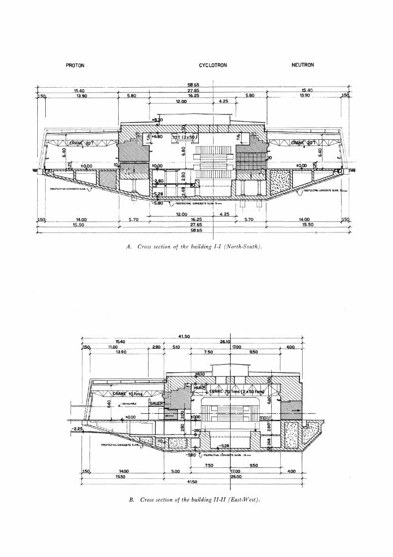
PROTON CYCLOTRON NEUTRON
.Q
5.80
I I
•
I _i -t------ 12.00_16_.2_5 _ _,,__4=.,,.25..,___,,_ ~"5-q. ____ - --,-d·2.~..,,.~,,,,o _____ j,,_. _ _,.,5_,_..1...,o._____,~------2"'1"".s""s'----1---_,,_ 5.70 14.00
~!-.------------------------~S=B.65 15.50
A. Cross section of the building I-I (North-South).
___ JS.4Q --------.J<--------
.,,...."'Jc------'-11~.oo.,,,__ ~~~~9=o._,,~~5~l~o _ _,.~ _____ _,__,_~.___ _____ __,,_-"~~o"'----' 13.90 7.50 9.50
4.00 -------~1=s.=so~ _____ __,~ __________ __,2~s=.o=o,__ _________ _,___
- - _____ __.4"'1.5"'0"'----------+-----------_,__
B. Cross section of the building II-II (East-West).

A. Multiplate J!Vilson cloud chamber.