symmetrical+faults+ - university of florida€¦ · 10/8/13 symmetrical&faults& 3...
TRANSCRIPT

SYMMETRICAL FAULTS
Revised: 10/8/13 1:49 PM
10/8/13 Symmetrical Faults 1

10/8/13 Symmetrical Faults 2
What is a “fault”? A faults is any failure which interferes with the normal flow of current. Most faults on transmission lines of 115 kV and higher are caused by lightning, which results in the flashover of insulators causing a low impedance path to ground. Line-‐to-‐line faults not involving ground are less common. Experience shows that 70 to 80% of transmission line failures are single line-‐to-‐ground faults. Permanent faults are caused by lines being on the ground, insulator strings breaking, ice loads, and equipment failure.

10/8/13 Symmetrical Faults 3
What is a “fault”? Roughly 5% of all faults involve all three phases and these are called symmetrical three-‐phase faults or just symmetrical faults. Line-‐to-‐line faults that do not involve ground and double line-‐to-‐ground faults are called unsymmetrical faults since they cause an imbalance between the phases. The currents which flow in a power system immediately a\er the occurrence of a fault differ from those flowing a few cycles later just before the circuit breakers are called upon to open the line on both sides of the fault.

10/8/13 Symmetrical Faults 4
What is a “fault”? Two factors which determine the proper selec^on of circuit breakers are the current flowing immediately a\er the fault occurs and the current which the breaker must interrupt. In fault analysis values of these currents are calculated for different types of faults at different loca^ons in the system. The informa^on obtained form these calcula^ons are used to determine the relay se_ng that control the circuit breakers.
10/8/13 Symmetrical Faults 5
Transients in Series RL Circuits The selec^on of a circuit breaker depends on: • normal opera^ng current • the current it has to interrupt • the maximum current it may have to momentarily carry
How does an over-‐current occur? To approach the problem of calcula^ng the ini^al current when a system is short-‐circuited, consider what happens when an ac voltage is applied to an RL circuit.

10/8/13 Symmetrical Faults 6
Mo^va^on – Transients in Series RL Circuits Differen^al equa^on: Solu^on:
R L
Vmax sin ωt +α( )
t = 0
i t( )
Vmax sin ωt +α( ) = Ri + L di
dt
i t( ) = Vmax
Zsin ωt +α −θ( )− e−Rt L sin α −θ( )⎡⎣ ⎤⎦
Z = R2 +ω 2L2 , θ = tan−1 ωL R( )

Mo^va^on – Transients in Series RL Circuits What about when a real synchronous generator is shorted?
10/8/13 Symmetrical Faults 7
i t( ) = Vmax
Zsin ωt +α −θ( )− e−Rt L sin α −θ( )⎡⎣ ⎤⎦
α −θ = 0
α −θ = − π
2
dc-‐component exponen^ally decaying
ac-‐component constant amplitude

Review of Synchronous Generators.
10/8/13 Symmetrical Faults 8
The Synchronous Generator The synchronous generator is driven by a turbine to convert mechanical energy into electrical energy. The windings of the synchronous machine consDtute a group of inducDvely coupled electric circuits, some of which rotate relaDve to others so that the mutual inductances are variable. The models developed for the the various windings are applicable to both steady-‐state and transient analysis. Only linear magneDc circuits are considered.
10/8/13 Symmetrical Faults 9
The Synchronous Generator The two principal parts of a synchronous machine are ferromagneDc structures. The staDonary part (a hollow cylinder), called the armature (see next slide), has longitudinal slots in which there are coils of the armature windings. These carry the current to an electrical load. The rotor is the part of the machine which is mounted on the shaM and rotates ins ide the hollow stator. The winding on the rotor, called the field winding, is supplied with dc current. The flux across the air gap between the armature and rotor generates voltages in the coils of the armature windings.
10/8/13 Symmetrical Faults 10

The Synchronous Generator – Two Types
10/8/13 Symmetrical Faults 11
Armature
Gap
The cylindrical rotor is called a non-salient pole machine.
Rotor
Armature
Gap
The non-cylindrical rotor is called a salient pole machine.
X
Rotor X
N S

The Synchronous Generator For the two-‐pole machine, one cycle of voltage is generated for each revoluDon of the two-‐pole rotor. In the four-‐pole machine, two cycles are generated in each armature coil per revoluDon. Since the number of cycles of revoluDon equals the number of pairs of poles, the frequency of the generated voltage is: where f is the electrical frequency in Hertz, P is the number of poles, N is the rotor speed in RPM, and fm = N/60 is the mechanical frequency in rpm. We see that a two-‐pole, 60 Hz machine operates at 3600 rpm, while a four-‐pole machine operates at 1800 rpm.
10/8/13 Symmetrical Faults 12
f = P
2N60
= P2
fm Hertz

The Synchronous Generator – Cylindrical Rotor, Non-‐Salient Pole Machine
10/8/13 Symmetrical Faults 13
Armature
Gap X
Rotor
X
N S d-‐axis
Direct Axis

The Synchronous Generator
10/8/13 Symmetrical Faults 14
Rotor
Armature
Gap
N N
S
S
q-‐axis
d-‐axis
The Synchronous Generator – Non-‐cylindrical Rotor, Salient Pole Machine WE’LL COME BACK TO THIS SHORTLY.
Direct Axis
Quadrature Axis

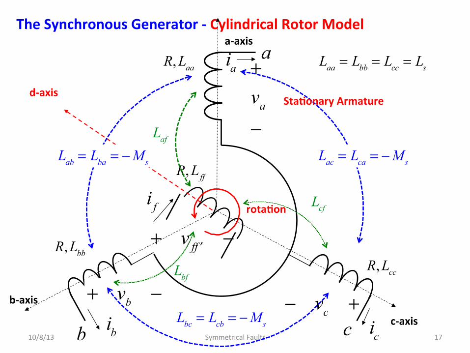
The Synchronous Generator -‐ Cylindrical Rotor Model
10/8/13 Symmetrical Faults 15
d-‐axis
a-‐axis
c-‐axis
b-‐axis
R, Laa
R, Lbb R, Lcc
R, Lff
ia
ib ic
+va
−
a
c b
i f
+ vb − − vc +
+ v f ′f −
rota^on
Sta^onary Armature
d-‐axis
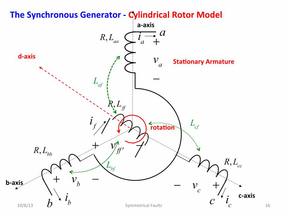
The Synchronous Generator -‐ Cylindrical Rotor Model
10/8/13 Symmetrical Faults 16
d-‐axis
a-‐axis
c-‐axis
b-‐axis
R, Laa
R, Lbb
R, Lcc
R, Lff
ia
ib ic
+va
−
a
c b
i f
+ vb − − vc +
+ v f ′f −
Laf
Lcf
Lbf
rota^on
Sta^onary Armature
The Synchronous Generator -‐ Cylindrical Rotor Model
10/8/13 Symmetrical Faults 17
d-‐axis
a-‐axis
c-‐axis
b-‐axis
R, Laa
R, Lbb
R, Lcc
R, Lff
ia
ib ic
+va
−
a
c b
i f
Laa = Lbb = Lcc = Ls
Lab = Lba = −Ms Lac = Lca = −Ms
Lbc = Lcb = −Ms
+ vb − − vc +
+ v f ′f −
Laf
Lcf
Lbf
rota^on
Sta^onary Armature
The Synchronous Generator -‐ Cylindrical Rotor Model
10/8/13 Symmetrical Faults 18
d-‐axis
a-‐axis
c-‐axis
b-‐axis
R, Laa
R, Lbb
R, Lcc
R, Lff
ia
ib ic
+va
−
a
c b
i f
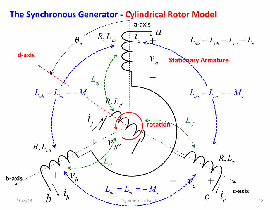
Laa = Lbb = Lcc = Ls
Lab = Lba = −Ms Lac = Lca = −Ms
Lbc = Lcb = −Ms
+ vb − − vc +
+ v f ′f −
Laf
Lcf
Lbf
θd
rota^on
Sta^onary Armature
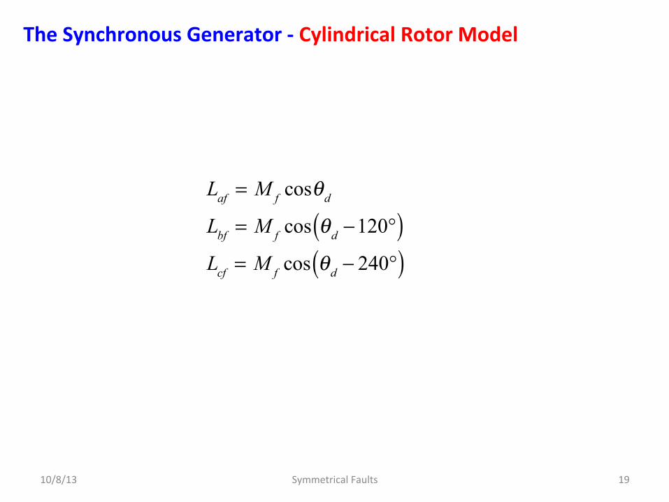
The Synchronous Generator -‐ Cylindrical Rotor Model
10/8/13 Symmetrical Faults 19
Laf = M f cosθd
Lbf = M f cos θd −120°( )Lcf = M f cos θd − 240°( )

Armature Flux Linkages Armature Flux Linkages Balanced Three-‐Phase System
10/8/13 Symmetrical Faults 20
λa = Laaia + Labib + Lacic + Laf i f = Lsia − Ms ib + ic( ) + Laf i f
λb = Lbaia + Lbbib + Lbcic + Lbf i f = Lsib − Ms ia + ic( ) + Lbf i f
λc = Lcaia + Lcbib + Lccic + Lcf i f = Lsic − Ms ia + ib( ) + Lcf i f
λ f = Laf ia + Lbf ib + Lcf ic + Lff i f
ia + ib + ic = 0
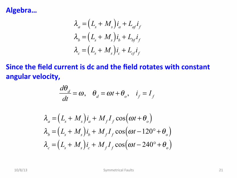
Algebra… Since the field current is dc and the field rotates with constant angular velocity,
10/8/13 Symmetrical Faults 21
λa = Ls + Ms( )ia + Laf i f
λb = Ls + Ms( )ib + Lbf i f
λc = Ls + Ms( )ic + Lcf i f
dθd
dt=ω , θd =ωt +θo , i f = I f
λa = Ls + Ms( )ia + M f I f cos ωt +θo( )λb = Ls + Ms( )ib + M f I f cos ωt −120° +θo( )λc = Ls + Ms( )ic + M f I f cos ωt − 240° +θo( )

Circuit Equa^ons Internal emf: (or synchronous emf) where: For convenience (it’s arbitrary anyway) set We have the circuit model…
10/8/13 Symmetrical Faults 22
va = −↑
Raia −↑
dλa
dt
generator
= −Raia − Ls + Ms( ) dia
dt+ ω M f I f sin ωt +θo( )
e ′a = 2 Ei sin ωt +θo( )
e ′a = 2 Ei sin ωt +θo( )
Ei =
ω M f I f
2
θo = δ + 90°

The Synchronous Generator -‐ Cylindrical Rotor Model
10/8/13 Symmetrical Faults 23
+
va
_+ _
~
ia
Ls + Ms
R
ib
ic
−
vb
+
−vc
+
e ′a = 2 Ei cos ωt +δ( )
e ′b e ′c
a
c
b
Ls + Ms Ls + Ms
R R
va = −Raia − Ls + Ms( ) dia
dt+ω M f I f sin ωt +θo( )
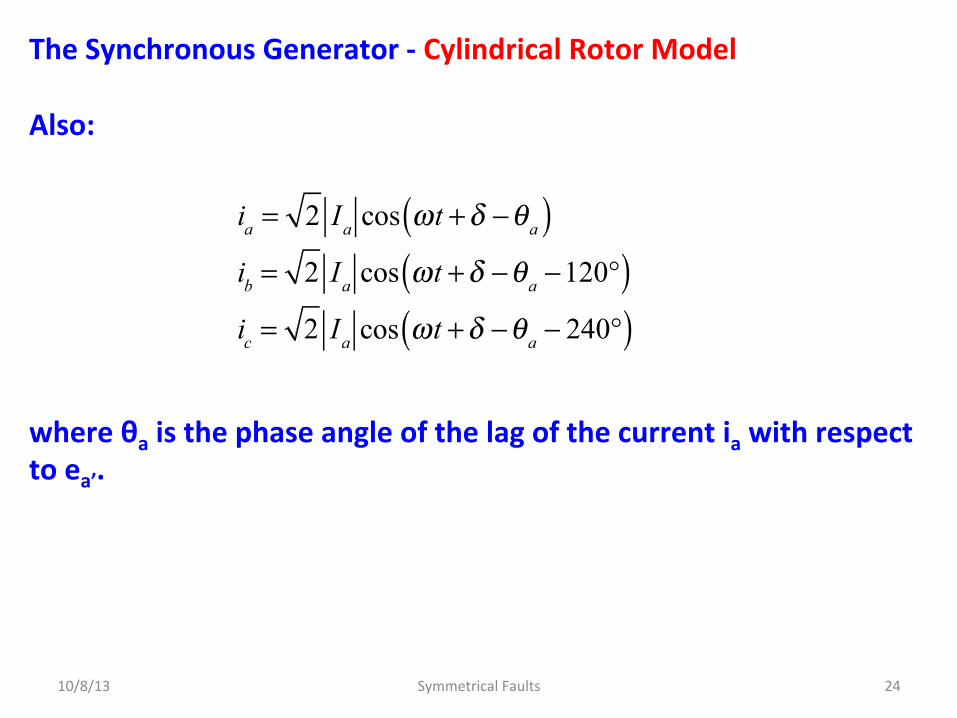
The Synchronous Generator -‐ Cylindrical Rotor Model Also: where θa is the phase angle of the lag of the current ia with respect to ea’.
10/8/13 Symmetrical Faults 24
ia = 2 Ia cos ωt +δ −θa( )ib = 2 Ia cos ωt +δ −θa −120°( )ic = 2 Ia cos ωt +δ −θa − 240°( )

The Synchronous Generator -‐ Cylindrical Rotor Model This is a steady-‐state model that misses details of the field current needed for transient analysis.
10/8/13 Symmetrical Faults 25
ia = 2 Ia cos ωt +δ −θa( )
±
+
va = 2 Va cosωt
−
Ls + Ms
e ′a = 2 Ei cos ωt +δ( )
R

The Synchronous Generator -‐ Cylindrical Rotor Model To facilitate transient analysis (as with a fault) it is necessary to recast this model into a different form. Recall: and: Subs^tu^ng:
10/8/13 Symmetrical Faults 26
λ f = Laf ia + Lbf ib + Lcf ic + Lff i f
Laf = M f cosθd
Lbf = M f cos θd −120°( )Lcf = M f cos θd − 240°( )
λ f = M f ia cosθd + ib cos θd −120°( ) + ic cos θd − 240°( )
⎡
⎣⎢⎢
⎤
⎦⎥⎥+ Lff i f
ia cosθd = 2 Ia cosθd cos ωt +δ −θa( )= 2 Ia cos ωt +δ + 90°( )cos ωt +δ −θa( )

To facilitate a symmetric fault it helps to recast this model a bit.
10/8/13 Symmetrical Faults 27
ia cosθd = 2 Ia cosθd cos ωt +δ −θa( )= 2 Ia cos ωt +δ + 90°( )cos ωt +δ −θa( )
=Ia
2cos θa + 90°( ) + cos 2ωt + 2δ −θa + 90°( )⎡⎣ ⎤⎦
=Ia
2−sinθa − sin 2ωt + 2δ −θa( )⎡⎣ ⎤⎦
2cosα cosβ = cos α − β( ) + cos α + β( )

ia cosθd + ib cos θd −120°( ) + ic cos θd − 240°( )
= −Ia
2
3sinθa
+sin 2ωt + 2δ −θa( ) + sin 2ωt + 2δ −θa −120°( ) + sin 2ωt + 2δ −θa − 240°( )= 0
⎡
⎣
⎢⎢⎢
⎤
⎦
⎥⎥⎥
= −3Ia
2sinθa
Similarly for the other two terms: Subs^tu^ng:
This is a balanced second harmonic terms that sums to zero at every point in Dme.
10/8/13 Symmetrical Faults 28
ib cos θd −120°( ) = Ia
2−sinθa − sin 2ωt + 2δ −θa −120°( )⎡⎣ ⎤⎦
ic cos θd − 240°( ) = Ia
2−sinθa − sin 2ωt + 2δ −θa − 240°( )⎡⎣ ⎤⎦
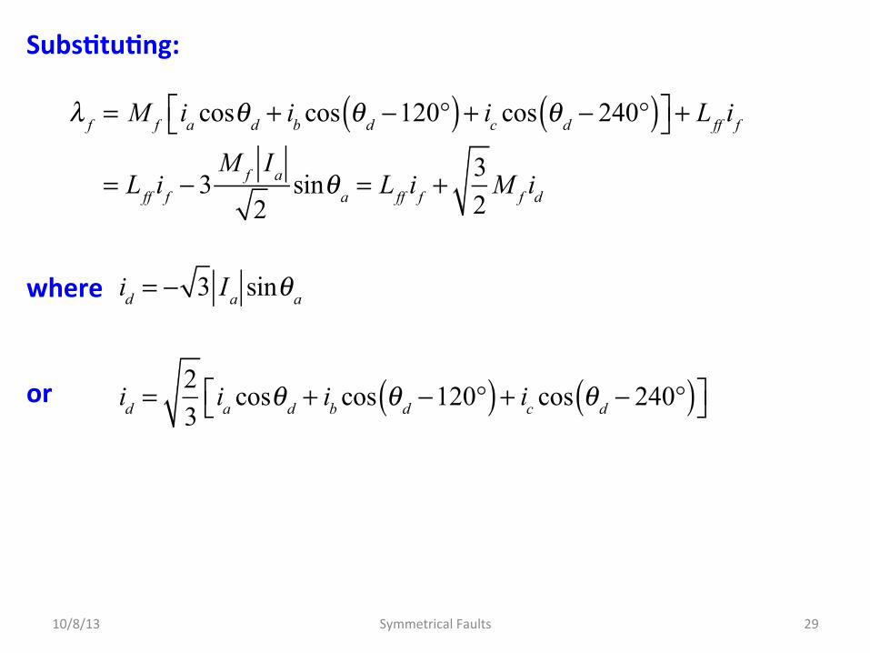
Subs^tu^ng: where or
10/8/13 Symmetrical Faults 29
λ f = M f ia cosθd + ib cos θd −120°( ) + ic cos θd − 240°( )⎡⎣ ⎤⎦ + Lff i f
= Lff i f − 3M f Ia
2sinθa = Lff i f +
32
M f id
id = − 3 Ia sinθa
id =23
ia cosθd + ib cos θd −120°( ) + ic cos θd − 240°( )⎡⎣ ⎤⎦
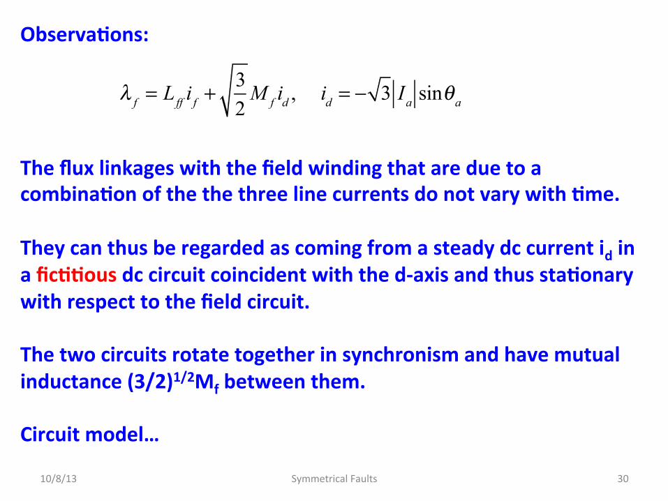
Observa^ons: The flux linkages with the field winding that are due to a combina^on of the the three line currents do not vary with ^me. They can thus be regarded as coming from a steady dc current id in a fic^^ous dc circuit coincident with the d-‐axis and thus sta^onary with respect to the field circuit. The two circuits rotate together in synchronism and have mutual inductance (3/2)1/2Mf between them. Circuit model…
10/8/13 Symmetrical Faults 30
λ f = Lff i f +
32
M f id , id = − 3 Ia sinθa

Alternate Circuit Model Suitable for Transient Analysis
10/8/13 Symmetrical Faults 31
d-‐axis
a-‐axis
c-‐axis
b-‐axis
R, Lff
i f
+ v f ′f
−
32
M f
θd
id
Field winding rota^ng with rotor
Armature equivalent winding rota^ng with rotor

Example – A 60-‐Hz three-‐phase synchronous generator with negligible armature resistance has the following inductance parameters: The machine is rated at 635 MVA, 0,9 power-‐factor lagging, 3600 rpm, 24 kV. When opera^ng under rated condi^ons, the line-‐to-‐neutral terminal voltage and the line current of phase a are Determine the magnitude of the synchronous internal voltage, the field current If, and the flux linkages with the field winding. Repeat these calcula^ons when a load of 635 MVA is served at rated voltage and unity power factor. What is the field current for rated armature voltage on a open circuit?
10/8/13 Symmetrical Faults 32
Laa = Ls = 2.7656mH , Lab = Ms = 1.3828mH
Lff = 433.6569mH , M f = 31.6950mH
va = 19596cosωt V , ia = 21603cos ωt − 25.6569°( )

Example Synchronous Internal Voltage:
10/8/13 Symmetrical Faults 33
vamax= 2
24,000
3= 19596V
iamax= VA
V= 2
635,000
3 × 24= 21603A
θ = cos−1 0.9 = 25.8419°, lagging
e ′a = 2 Ei cos ωt +δ( )= Ra
=0ia + va + Ls + Ms( ) dia
dt= va + 2.7656+1.3828( )10−3 dia
dt
= 19596cosωt + 21603 2.7656+1.3828( )10−3 ddt
cos ωt − 25.6569°( )= 19596cosωt −ω21603 2.7656+1.3828( )10−3 sin ωt − 25.6569°( )

Example Synchronous Internal Voltage: Field Current:
10/8/13 Symmetrical Faults 34
2 Ei cos ωt +δ( )= 19596cosωt −ω21603 2.7656+1.3828( )10−3 sin ωt − 25.6569°( )= 19596cosωt − 33875sin ωt − 25.6569°( )= 34323cosωt − 30407sinωt= 45855cos ωt + 41.5384°( )⇒ 2 Ei = 45855, δ = 41.5384°
ω = 120πsin x − y( ) = sin xcos y − cos xsin y
Ei =
ω M f I f
2⇒ I f = 2
Ei
ω M f
= 3838A

Example Flux linkages with field windings: θa is the angle of lag measured wrt ea’. Since ia lags 25.8419o behind va, which lags 41.5384o behind ea’, then θa = 25.8419o + 41.5384o = 67.3803o Thus:
10/8/13 Symmetrical Faults 35
λ f = Lff i f − 3
M f Ia
2sinθa
Ia sinθa =
216032
sin67.3803° = 14100.6A
λ f = Lff i f − 3M f Ia
2sinθa
= 433.6569× 3838×10−3 − 3× 31.69502
×14100.6×10−3
= 1664.38− 948.06 = 716.31 Weber-turns

Example – Repea^ng for unity power factor: The current ia is in-‐phase with va, and lags ea’ by 59.8854o
10/8/13 Symmetrical Faults 36
e ′a = 2 Ei cos ωt +δ( ) = va + 2.7656+1.3828( )10−3 dia
dt= 19596cosωt − 33785sinωt = 39057cos ωt +59.8854°( )
I f = 2
Ei
ω M f
= 3905745855
× 3838 = 3269A
Ia sinθa = 15276sin59.8854° = 13214A
λ f = 433.6569× 3269×10−3 − 3× 31.69502
×13214×10−3
= 1417.62−888.43= 529.19 Weber-turns

Example – We see that when the power factor of the load goes from 0.9 lagging to 1.0 under rated mega-‐voltamperes loading and voltage condiDons, the field current is reduced from 3838 to 3269 A . Also, the net air-‐gap flux linking the field winding of the generator is reduced along with the demagneDzing influence of armature reacDon. The field current required to maintain rated terminal voltage in the machine under open-‐circuit condiDons (ia = 0) is
10/8/13 Symmetrical Faults 37
I f = 2
Ei
ω M f
= 19596×103
120π × 31.695= 1640A

The Synchronous Generator -‐ Salient Rotor Model The round-‐rotor theory already just considered gives good results for the steady-‐state performance of the synchronous machine. However, for transient analysis we need to consider a two-‐axis model. We now introduce the two-‐axis model by means of the equaDons of the salient-‐pole machine in which the air gap varies between poles. The largest generaDng units are steam-‐turbine driven with round-‐rotor construcDon; fossil-‐fired units have two poles and nuclear units have four pole s for reasons of economical design and efficiency. Hydroelectric generators usually have more pole-‐pairs and are of salient-‐pole construcDon. These units run at lower speeds so as to avoid mechanical damage due to centrifugal forces.
10/8/13 Symmetrical Faults 38

The Synchronous Generator -‐ Salient Rotor Model The three-‐phase salient-‐pole machine, like its round-‐rotor counterpart, has three symmetrically distributed armature windings a, b, and c, and a field winding f on the rotor which produces a sinusoidal flux distribuDon around the air gap. In both types of machines the field “sees” the same air gap and magneDzing paths in the stator regardless of the rotor posiDon. Thus, the field winding has constant self-‐inductance Lff. Moreover, both machine have the same sinusoidal varying mutual inductances as before. The difference is that the self-‐ inductances Laa , Lbb, and Lcc and the mutual inductances Lab, Lbc, and Lca between them are no longer constant but also vary as a funcDon of the rotor angular displacement.
10/8/13 Symmetrical Faults 39
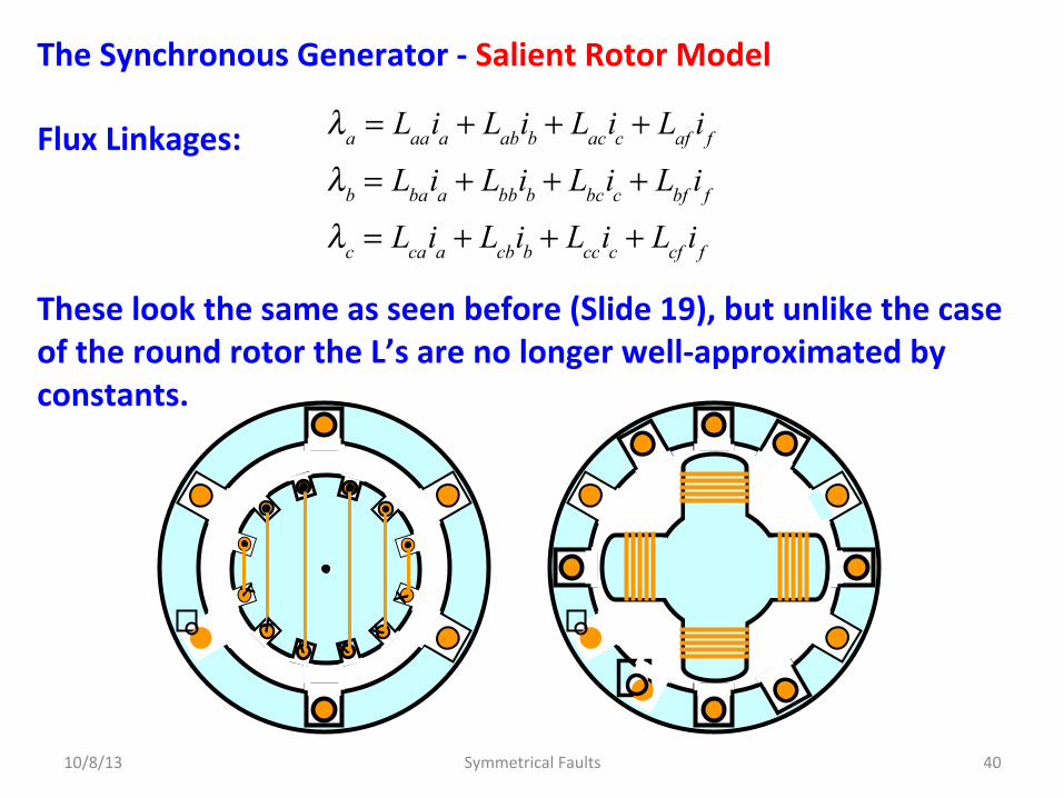
The Synchronous Generator -‐ Salient Rotor Model Flux Linkages: These look the same as seen before (Slide 19), but unlike the case of the round rotor the L’s are no longer well-‐approximated by constants.
10/8/13 Symmetrical Faults 40
λa = Laaia + Labib + Lacic + Laf i f
λb = Lbaia + Lbbib + Lbcic + Lbf i f
λc = Lcaia + Lcbib + Lccic + Lcf i f
X X

The Synchronous Generator -‐ Salient Rotor Model For the armature, Self-‐inductances: Mutual-‐inductances:
10/8/13 Symmetrical Faults 41
Laa = Ls + Lm cos2θd
Lbb = Ls + Lm cos2 θd − 2π 3( )Lcc = Ls + Lm cos2 θd + 2π 3( )
Ls > Lm > 0
Lab = Lba = −Ms − Lm cos2 θd +π 6( )Lbc = Lcb = −Ms − Lm cos2 θd −π 2( )Lca = Lac = −Ms − Lm cos2 θd +5π 6( )
Ms > Lm > 0Mostly based on geometrical considera^ons

The Synchronous Generator -‐ Salient Rotor Model For the rotor, Self-‐inductances:
Field winding: D-‐Damper winding: Q-‐Damper winding:
Mutual-‐inductances:
Field/D-‐winding: Field/Q-‐winding: D-‐winding/Q-‐winding:
Armature/Field:
10/8/13 Symmetrical Faults 42
Lff
LD
LQ
Mr
00
Laf = Lfa = M f cos2θd
Lbf = Lfb = M f cos2 θd − 2π 3( )Lcf = Lfc = M f cos2 θd − 4π 3( )
Mostly based on geometrical considera^ons

The Synchronous Generator -‐ Salient Rotor Model Armature-‐damper winding mutual-‐inductances, Armature/D-‐winding: Armature/Q-‐winding:
10/8/13 Symmetrical Faults 43
LaD = LDa = M D cos2θd
LbD = LDb = M D cos2 θd − 2π 3( )LcD = LDc = M D cos2 θd − 4π 3( )
LaQ = LQa = MQ cos2θd
LbQ = LQb = MQ cos2 θd − 2π 3( )LcQ = LQc = MQ cos2 θd − 4π 3( )
Mostly based on geometrical considera^ons
What are these?

The Synchronous Generator -‐ Salient Rotor Model
10/8/13 Symmetrical Faults 44
Field Windings
Damper Windings or Amortisseur Windings
Shorting Bar

Two-‐Axis Machine Model Clearly the equaDons for the flux linkages of the salient-‐pole machine are more complicated than their round-‐rotor counterparts. Fortunately, the equaDons of the salient-‐pole machine can °be expressed in a simple form by transforming the a , b, and c variables of the stator into corresponding sets of new variables, called the direct-‐axis , quadrature-‐axis , and zero-‐sequence quanDDes which are disDnguished by the subscripts d, q , and 0: respecDvely. The three stator currents ia, ib, and ic can be transformed into three equivalent currents, called the direct-‐axis current id, the quadrature-‐axis current iq and the zero-‐sequence current io. The transformaDon is made by a matrix P called Park’s Transforma^on.
10/8/13 Symmetrical Faults 45

Park’s Transforma^on Recall for the round rotor machine we found (Slide 30) id, what we will now call the direct current as: Note how the q-‐axis lags the d-‐axis by – 90-‐degrees.
10/8/13 Symmetrical Faults 46
id =
23
ia cosθd + ib cos θd −120°( ) + ic cos θd − 240°( )⎡⎣ ⎤⎦
X X
N S d-‐axis N N
d-‐axis
q-‐axis
Direct Axis
Quadrature Axis
S
S
rota^on

Park’s Transforma^on Note how the q-‐axis lags the d-‐axis by – 90-‐degrees. Define P as a unitary matrix: The unitary property assures that the power is unaltered by P.
10/8/13 Symmetrical Faults 47
id =23
ia cosθd + ib cos θd −120°( ) + ic cos θd − 240°( )⎡⎣ ⎤⎦
iq =23
ia sinθd + ib sin θd −120°( ) + ic sin θd − 240°( )⎡⎣ ⎤⎦
P = 23
cosθd cos θd −120°( ) cos θd − 240°( )sinθd sin θd −120°( ) sin θd − 240°( )
? ? ?
⎡
⎣
⎢⎢⎢⎢
⎤
⎦
⎥⎥⎥⎥
P−1 = PT

Park’s Transforma^on Park’s transformaDon gives what is known as the Two-‐Axis Model of a salient pole generator.
10/8/13 Symmetrical Faults 48
P = 23
cosθd cos θd −120°( ) cos θd − 240°( )sinθd sin θd −120°( ) sin θd − 240°( )
1
2
1
2
1
2
⎡
⎣
⎢⎢⎢⎢⎢⎢
⎤
⎦
⎥⎥⎥⎥⎥⎥
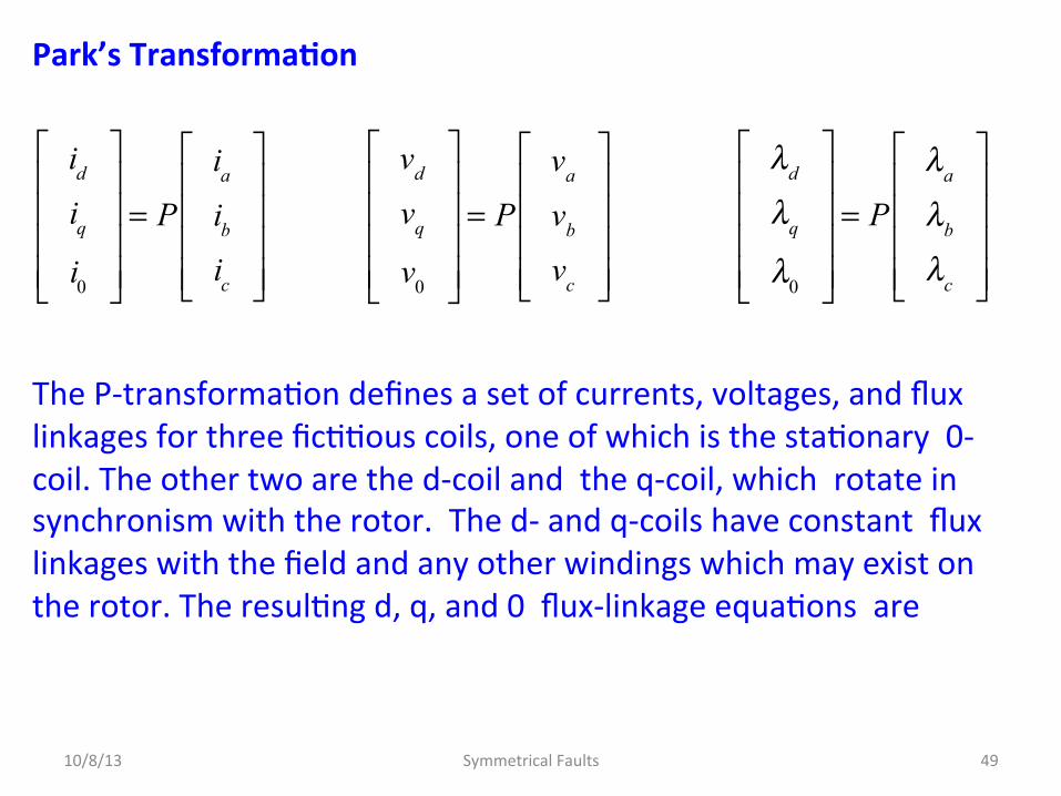
Park’s Transforma^on The P-‐transformaDon defines a set of currents, voltages, and flux linkages for three ficDDous coils, one of which is the staDonary 0-‐coil. The other two are the d-‐coil and the q-‐coil, which rotate in synchronism with the rotor. The d-‐ and q-‐coils have constant flux linkages with the field and any other windings which may exist on the rotor. The resulDng d, q, and 0 flux-‐linkage equaDons are
10/8/13 Symmetrical Faults 49
id
iqi0
⎡
⎣
⎢⎢⎢⎢
⎤
⎦
⎥⎥⎥⎥
= Pia
ibic
⎡
⎣
⎢⎢⎢⎢
⎤
⎦
⎥⎥⎥⎥
vd
vq
v0
⎡
⎣
⎢⎢⎢⎢
⎤
⎦
⎥⎥⎥⎥
= Pva
vb
vc
⎡
⎣
⎢⎢⎢⎢
⎤
⎦
⎥⎥⎥⎥
λd
λq
λ0
⎡
⎣
⎢⎢⎢⎢
⎤
⎦
⎥⎥⎥⎥
= Pλa
λb
λc
⎡
⎣
⎢⎢⎢⎢
⎤
⎦
⎥⎥⎥⎥

Park’s Transforma^on For example, the resulDng d, q, and 0 flux-‐linkage equaDons are from the stator flux-‐linkages as follows:
10/8/13 Symmetrical Faults 50
λa = Laaia + Labib + Lacic + Laf i f
λb = Lbaia + Lbbib + Lbcic + Lbf i f
λc = Lcaia + Lcbib + Lccic + Lcf i f
⎫
⎬⎪⎪
⎭⎪⎪
⇒
λa
λb
λc
⎡
⎣
⎢⎢⎢⎢
⎤
⎦
⎥⎥⎥⎥
=
Laa Lab Lac
Lab Lbb Lbc
Lac Lbc Lcc
⎡
⎣
⎢⎢⎢⎢
⎤
⎦
⎥⎥⎥⎥
ia
ibic
⎡
⎣
⎢⎢⎢⎢
⎤
⎦
⎥⎥⎥⎥
+
Laf
Lbf
Lcf
⎡
⎣
⎢⎢⎢⎢
⎤
⎦
⎥⎥⎥⎥
i f
λd
λq
λ0
⎡
⎣
⎢⎢⎢⎢
⎤
⎦
⎥⎥⎥⎥
= Pλa
λb
λc
⎡
⎣
⎢⎢⎢⎢
⎤
⎦
⎥⎥⎥⎥
⇒
λa
λb
λc
⎡
⎣
⎢⎢⎢⎢
⎤
⎦
⎥⎥⎥⎥
= P−1
λd
λq
λ0
⎡
⎣
⎢⎢⎢⎢
⎤
⎦
⎥⎥⎥⎥
P−1
λd
λq
λ0
⎡
⎣
⎢⎢⎢⎢
⎤
⎦
⎥⎥⎥⎥
=
Laa Lab Lac
Lab Lbb Lbc
Lac Lbc Lcc
⎡
⎣
⎢⎢⎢⎢
⎤
⎦
⎥⎥⎥⎥
P−1
λd
λq
λ0
⎡
⎣
⎢⎢⎢⎢
⎤
⎦
⎥⎥⎥⎥
+
Laf
Lbf
Lcf
⎡
⎣
⎢⎢⎢⎢
⎤
⎦
⎥⎥⎥⎥
i f
λd
λq
λ0
⎡
⎣
⎢⎢⎢⎢
⎤
⎦
⎥⎥⎥⎥
= PLaa Lab Lac
Lab Lbb Lbc
Lac Lbc Lcc
⎡
⎣
⎢⎢⎢⎢
⎤
⎦
⎥⎥⎥⎥
P−1
λd
λq
λ0
⎡
⎣
⎢⎢⎢⎢
⎤
⎦
⎥⎥⎥⎥
+ P
Laf
Lbf
Lcf
⎡
⎣
⎢⎢⎢⎢
⎤
⎦
⎥⎥⎥⎥
i f

Park’s Transforma^on SubsDtuDng for the L’s from the previous table:
10/8/13 Symmetrical Faults 51
Laa Lab Lac
Lab Lbb Lbc
Lac Lbc Lcc
⎡
⎣
⎢⎢⎢⎢
⎤
⎦
⎥⎥⎥⎥
=
Ls + Lm cos2θd −Ms − Lm cos2 θd +π 6( ) −Ms − Lm cos2 θd +5π 6( )−Ms − Lm cos2 θd +π 6( ) Ls + Lm cos2 θd − 2π 3( ) −Ms − Lm cos2 θd −π 2( )−Ms − Lm cos2 θd +5π 6( ) −Ms − Lm cos2 θd −π 2( ) Ls + Lm cos2 θd + 2π 3( )
⎡
⎣
⎢⎢⎢⎢
⎤
⎦
⎥⎥⎥⎥
=
Ls −Ms −Ms
−Ms Ls −Ms
−Ms −Ms Ls
⎡
⎣
⎢⎢⎢⎢
⎤
⎦
⎥⎥⎥⎥
− Lm
−cos2θd cos2 θd +π 6( ) cos2 θd +5π 6( )cos2 θd +π 6( ) −cos2 θd − 2π 3( ) cos2 θd −π 2( )cos2 θd +5π 6( ) cos2 θd −π 2( ) −cos2 θd + 2π 3( )
⎡
⎣
⎢⎢⎢⎢
⎤
⎦
⎥⎥⎥⎥
= Ls + Ms( )1 0 00 1 00 0 1
⎡
⎣
⎢⎢⎢
⎤
⎦
⎥⎥⎥− M
1 1 11 1 11 1 1
⎡
⎣
⎢⎢⎢
⎤
⎦
⎥⎥⎥− Lm
−cos2θd cos2 θd +π 6( ) cos2 θd +5π 6( )cos2 θd +π 6( ) −cos2 θd − 2π 3( ) cos2 θd −π 2( )cos2 θd +5π 6( ) cos2 θd −π 2( ) −cos2 θd + 2π 3( )
⎡
⎣
⎢⎢⎢⎢
⎤
⎦
⎥⎥⎥⎥

Park’s Transforma^on Now for the tedious part – subsDtute all this… to get…
10/8/13 Symmetrical Faults 52
Laa Lab Lac
Lab Lbb Lbc
Lac Lbc Lcc
⎡
⎣
⎢⎢⎢⎢
⎤
⎦
⎥⎥⎥⎥
= Ls + Ms( )1 0 00 1 00 0 1
⎡
⎣
⎢⎢⎢
⎤
⎦
⎥⎥⎥− M
1 1 11 1 11 1 1
⎡
⎣
⎢⎢⎢
⎤
⎦
⎥⎥⎥− Lm
−cos2θd cos2 θd +π 6( ) cos2 θd +5π 6( )cos2 θd +π 6( ) −cos2 θd − 2π 3( ) cos2 θd −π 2( )cos2 θd +5π 6( ) cos2 θd −π 2( ) −cos2 θd + 2π 3( )
⎡
⎣
⎢⎢⎢⎢
⎤
⎦
⎥⎥⎥⎥
λd
λq
λ0
⎡
⎣
⎢⎢⎢⎢
⎤
⎦
⎥⎥⎥⎥
= PLaa Lab Lac
Lab Lbb Lbc
Lac Lbc Lcc
⎡
⎣
⎢⎢⎢⎢
⎤
⎦
⎥⎥⎥⎥
P−1
λd
λq
λ0
⎡
⎣
⎢⎢⎢⎢
⎤
⎦
⎥⎥⎥⎥
+ P
M f cos2θd
M f cos2 θd − 2π 3( )M f cos2 θd − 4π 3( )
⎡
⎣
⎢⎢⎢⎢
⎤
⎦
⎥⎥⎥⎥
i f
P = 23
cosθd cos θd −120°( ) cos θd − 240°( )sinθd sin θd −120°( ) sin θd − 240°( )
1
2
1
2
1
2
⎡
⎣
⎢⎢⎢⎢⎢⎢
⎤
⎦
⎥⎥⎥⎥⎥⎥
, P−1 = PT

Park’s Transforma^on to get… where:
Direct-‐axis inductance:
Quadrature-‐axis inductance:
Zero-‐sequence inductance:
all constants!
10/8/13 Symmetrical Faults 53
λd
λq
λ0
⎡
⎣
⎢⎢⎢⎢
⎤
⎦
⎥⎥⎥⎥
=
Ld 0 0
0 Lq 0
0 0 L0
⎡
⎣
⎢⎢⎢⎢
⎤
⎦
⎥⎥⎥⎥
id
iqi0
⎡
⎣
⎢⎢⎢⎢
⎤
⎦
⎥⎥⎥⎥
+
32
M f
00
⎡
⎣
⎢⎢⎢⎢⎢
⎤
⎦
⎥⎥⎥⎥⎥
i f
Ld = Ls + Ms +
32
Lm
Lq = Ls + Ms −
32
Lm
L0 = Ls − 2Ms
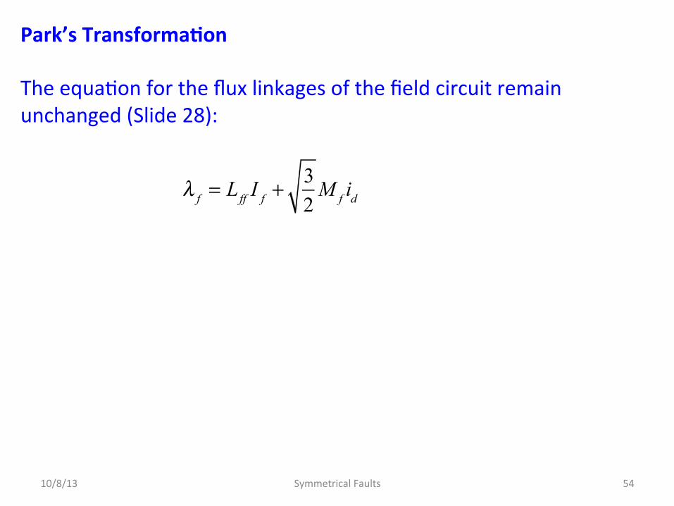
Park’s Transforma^on The equaDon for the flux linkages of the field circuit remain unchanged (Slide 28):
10/8/13 Symmetrical Faults 54
λ f = Lff I f +
32
M f id
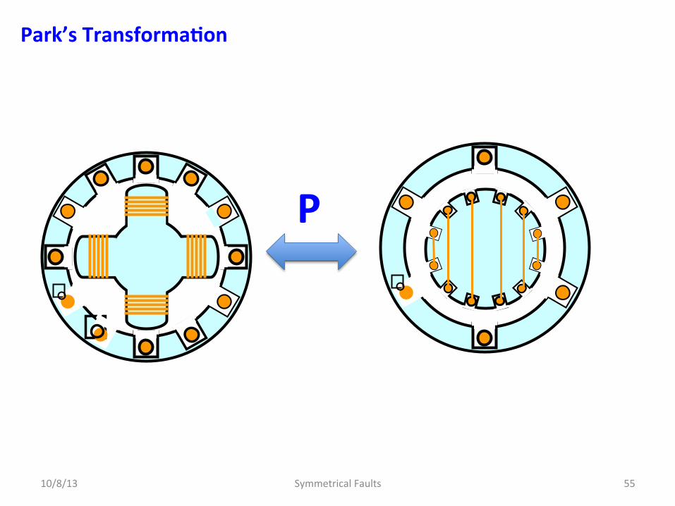
Park’s Transforma^on
10/8/13 Symmetrical Faults 55
P
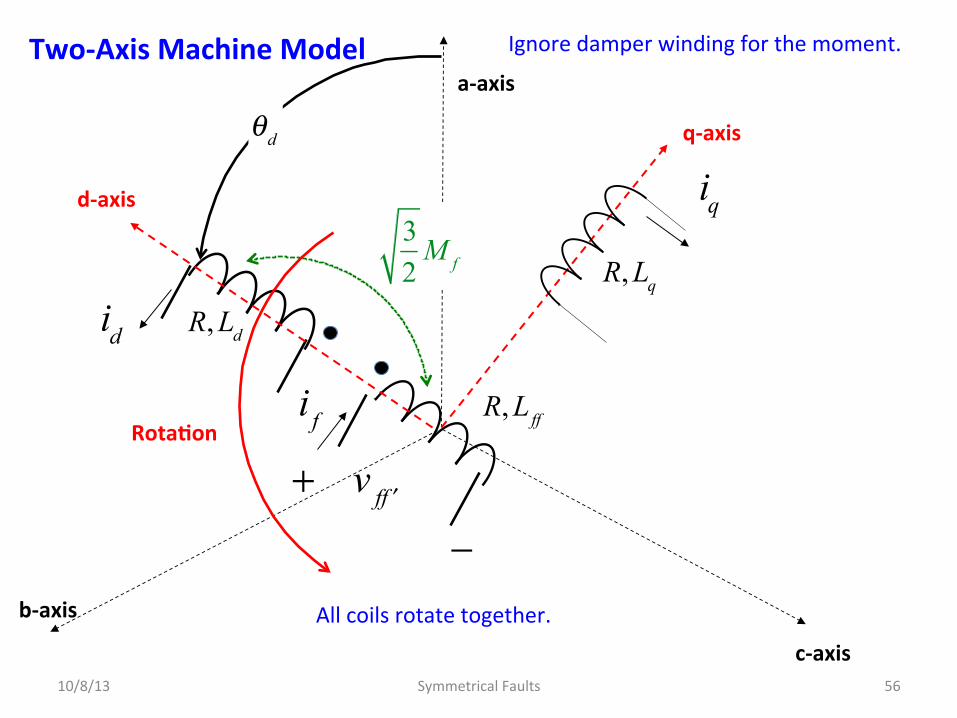
Two-‐Axis Machine Model
10/8/13 Symmetrical Faults 56
q-‐axis
a-‐axis
c-‐axis
b-‐axis
R, Lff
i f
+ v f ′f
−
32
M f
iq
All coils rotate together.
d-‐axis
Rota^on
θd
R, Lq
R, Ld id
Ignore damper winding for the moment.
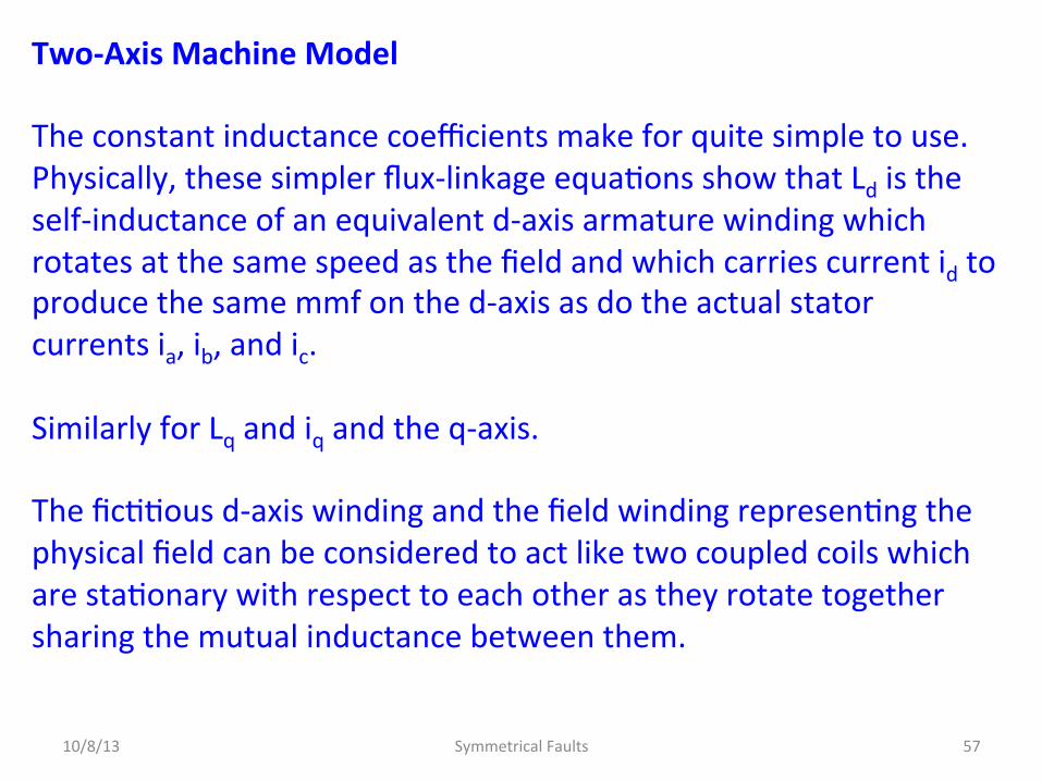
Two-‐Axis Machine Model The constant inductance coefficients make for quite simple to use. Physically, these simpler flux-‐linkage equaDons show that Ld is the self-‐inductance of an equivalent d-‐axis armature winding which rotates at the same speed as the field and which carries current id to produce the same mmf on the d-‐axis as do the actual stator currents ia, ib, and ic. Similarly for Lq and iq and the q-‐axis. The ficDDous d-‐axis winding and the field winding represenDng the physical field can be considered to act like two coupled coils which are staDonary with respect to each other as they rotate together sharing the mutual inductance between them.
10/8/13 Symmetrical Faults 57
Two-‐Axis Machine Model Furthermore, the field and the d-‐axis coil do not couple magneDcally with ficDDous q winding since it lags the d-‐axis in space by 90°. The zero-‐sequence inductance L0 is associated with a staDonary ficDDous armature coil with no coupling to any other coils. Under balanced condiDons this coil carries no current, and therefore we omit it from our discussion .
10/8/13 Symmetrical Faults 58

Example – To get a feeling for Park’s Transforma^on Under steady-‐state operaDng condiDons the armature of the salient-‐pole synchronous generator carries symmetrical sinusoidal three-‐phase currents: Find the corresponding d-‐q-‐0 currents of the armature.
10/8/13 Symmetrical Faults 59
ia = 2 Ia sin θd −θa( )ib = 2 Ia sin θd −120°−θa( )ic = 2 Ia sin θd − 240°−θa( )

Example – To get a feeling for Park’s Transforma^on MulDply through:
balanced three-‐phase
10/8/13 Symmetrical Faults 60
id
iqi0
⎡
⎣
⎢⎢⎢⎢
⎤
⎦
⎥⎥⎥⎥
= 23
cosθd cos θd −120°( ) cos θd − 240°( )sinθd sin θd −120°( ) sin θd − 240°( )
1
2
1
2
1
2
⎡
⎣
⎢⎢⎢⎢⎢⎢
⎤
⎦
⎥⎥⎥⎥⎥⎥
ia
ibic
⎡
⎣
⎢⎢⎢⎢
⎤
⎦
⎥⎥⎥⎥
id =23
cosθdia + cos θd −120°( )ib + cos θd − 240°( )ic⎡⎣ ⎤⎦
iq =23
sinθdia + sin θd −120°( )ib + sin θd − 240°( )ic⎡⎣ ⎤⎦
i0 =23
1
2ia + ib + ic( )⎡
⎣⎢
⎤
⎦⎥ = 0

Example – To get a feeling for Park’s Transforma^on Simplifying…
10/8/13 Symmetrical Faults 61
2sin xcos y = sin x + y( ) + sin x − y( )
ia cosθd = 2 Ia sin θd −θa( )cosθd =Ia
2sin 2θd −θa( )− sinθa⎡⎣ ⎤⎦
ib cos θd −120°( ) = 2 Ia cos θd −120°( )sin θd −120°−θd( )=
Ia
2sin 2θd − 240°−θa( )− sinθa⎡⎣ ⎤⎦
ic cos θd − 240°( ) = 2 Ia cos θd − 240°( )sin θd − 240°−θd( )=
Ia
2sin 2θd − 480°−θa( )− sinθa⎡⎣ ⎤⎦
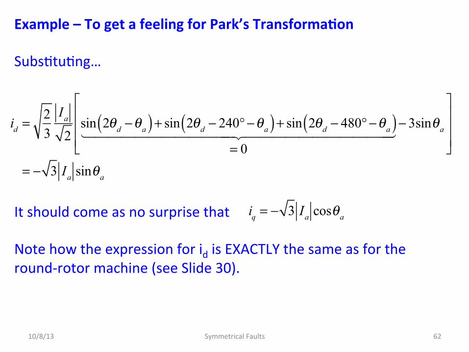
Example – To get a feeling for Park’s Transforma^on SubsDtuDng… It should come as no surprise that Note how the expression for id is EXACTLY the same as for the round-‐rotor machine (see Slide 30).
10/8/13 Symmetrical Faults 62
id =23
Ia
2sin 2θd −θa( ) + sin 2θd − 240°−θa( ) + sin 2θd − 480°−θa( )
= 0
− 3sinθa
⎡
⎣
⎢⎢⎢
⎤
⎦
⎥⎥⎥
= − 3 Ia sinθa
iq = − 3 Ia cosθa

VOLTAGE EQUATIONS Remarkably simple in d, q, 0 variables. As before, the line to neutral voltages are: These would be EXTREMELY difficult to deal with if leM in terms of a, b, c, but simplify TREMENDOUSLY using Park’s transformaDon, but going from a, b, c to d, q, 0 is a bit tedious.
10/8/13 Symmetrical Faults 63
va = −↑
Ria −↑
dλa
dt
generator
vb = −Rib −dλb
dt
vc = −Ric −dλc
dt

Voltage Equa^ons General procedure – lots of algebra:
MulDply both sides by P Note: since
10/8/13 Symmetrical Faults 64
va
vb
vc
⎡
⎣
⎢⎢⎢⎢
⎤
⎦
⎥⎥⎥⎥
= −Ria
ibic
⎡
⎣
⎢⎢⎢⎢
⎤
⎦
⎥⎥⎥⎥
− ddt
λa
λb
λc
⎡
⎣
⎢⎢⎢⎢
⎤
⎦
⎥⎥⎥⎥
⇒ Pva
vb
vc
⎡
⎣
⎢⎢⎢⎢
⎤
⎦
⎥⎥⎥⎥
= −RPia
ibic
⎡
⎣
⎢⎢⎢⎢
⎤
⎦
⎥⎥⎥⎥
− P ddt
λa
λb
λc
⎡
⎣
⎢⎢⎢⎢
⎤
⎦
⎥⎥⎥⎥
vd
vq
v0
⎡
⎣
⎢⎢⎢⎢
⎤
⎦
⎥⎥⎥⎥
= −R
id
iqi0
⎡
⎣
⎢⎢⎢⎢
⎤
⎦
⎥⎥⎥⎥
− P ddt
P−1
λd
λq
λ0
⎡
⎣
⎢⎢⎢⎢
⎤
⎦
⎥⎥⎥⎥
⎛
⎝
⎜⎜⎜⎜
⎞
⎠
⎟⎟⎟⎟
θd =ωt +θo P = P t( )

vd
vq
v0
⎡
⎣
⎢⎢⎢⎢
⎤
⎦
⎥⎥⎥⎥
= −R
id
iqi0
⎡
⎣
⎢⎢⎢⎢
⎤
⎦
⎥⎥⎥⎥
− P ddt
P−1
λd
λq
λ0
⎡
⎣
⎢⎢⎢⎢
⎤
⎦
⎥⎥⎥⎥
⎛
⎝
⎜⎜⎜⎜
⎞
⎠
⎟⎟⎟⎟
= −R
id
iqi0
⎡
⎣
⎢⎢⎢⎢
⎤
⎦
⎥⎥⎥⎥
− PP−1 ddt
λd
λq
λ0
⎡
⎣
⎢⎢⎢⎢
⎤
⎦
⎥⎥⎥⎥
− P ddt
P−1⎛⎝⎜
⎞⎠⎟
λd
λq
λ0
⎡
⎣
⎢⎢⎢⎢
⎤
⎦
⎥⎥⎥⎥
= −R
id
iqi0
⎡
⎣
⎢⎢⎢⎢
⎤
⎦
⎥⎥⎥⎥
− ddt
λd
λq
λ0
⎡
⎣
⎢⎢⎢⎢
⎤
⎦
⎥⎥⎥⎥
− P ddt
PT⎛⎝⎜
⎞⎠⎟
λd
λq
λ0
⎡
⎣
⎢⎢⎢⎢
⎤
⎦
⎥⎥⎥⎥
Voltage Equa^ons General procedure – lots of algebra:
10/8/13 Symmetrical Faults 65
This is the work.
vd
vq
v0
⎡
⎣
⎢⎢⎢⎢
⎤
⎦
⎥⎥⎥⎥
= −R
id
iqi0
⎡
⎣
⎢⎢⎢⎢
⎤
⎦
⎥⎥⎥⎥
−
dλd
dtdλq
dtdλ0
dt
⎡
⎣
⎢⎢⎢⎢⎢⎢⎢⎢
⎤
⎦
⎥⎥⎥⎥⎥⎥⎥⎥
+−ωλq
ωλd
0
⎡
⎣
⎢⎢⎢⎢
⎤
⎦
⎥⎥⎥⎥
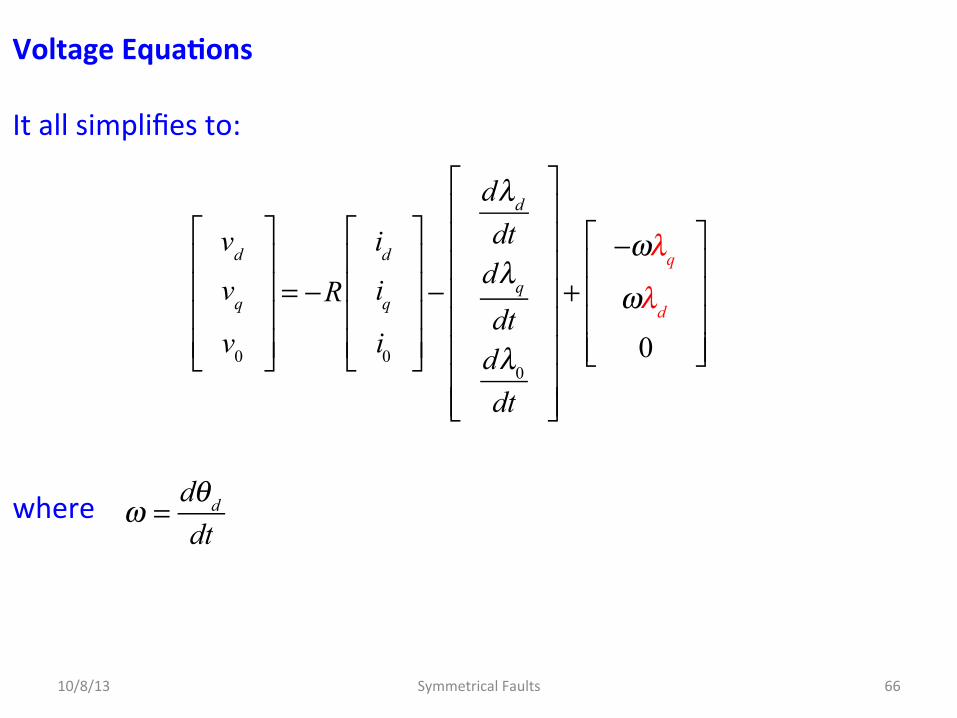
Voltage Equa^ons It all simplifies to: where
10/8/13 Symmetrical Faults 66
ω =
dθd
dt

Voltage Equa^ons Summary: d-‐axis q-‐axis and since the field winding is not subject to the P-‐transformaDon
vd = −Rid −dλd
dt−ωλq
λ f = Lff i f +32
M f id
λd = Ldid +32
M f if
10/8/13 Symmetrical Faults 67
vq = −Riq −dλq
dt+ωλd
λq = Lqiq
v f ′f = Rf i f +
dλ f
dt

Circuit Model
10/8/13 Symmetrical Faults 68
v f ′f = Rf i f +
dλ f
dt
v f ′f
Rf
Lff
vd = −Rid − Ld
did
dt−ωλq
32
M f
id
iq
+vd
−
+vq
−
−ωλq +
+ωλd −
vq = −Riq − Lq
diqdt
−ωλd
Ld
Lq
R
R
d-‐axis armature equivalent winding
q-‐axis armature equivalent winding
i f
Field winding

Circuit Model We see that the field coil is mutually coupled to the d-‐coil on the d-‐axis. The q-‐coil is magneDcally uncoupled from the other two windings since the d-‐axis and the q-‐axis are spaDally in quadrature with one another. However, there is interacDon between the two axes by means of the voltage sources which are rotaDonal emfs or speed voltages internal to the machine due to the rotaDon of the rotor. Note that the speed voltage in the d-‐axis depends on λq, and similarly, the speed voltage in the q-‐axis depends on λd. These sources represent ongoing electromechanical energy conversion.
10/8/13 Symmetrical Faults 69

Example – No numbers, but again to appreciate the model A direct current If is supplied to the field winding of an unloaded salient-‐pole synchronous generator rotaDng with constant angular velocity ω. Determine the open-‐circuit armature voltages and their d-‐q-‐0 components. Since open circuited: SubsDtuDng these into: gives…
10/8/13 Symmetrical Faults 70
id
iqi0
⎡
⎣
⎢⎢⎢⎢
⎤
⎦
⎥⎥⎥⎥
= Pia
ibic
⎡
⎣
⎢⎢⎢⎢
⎤
⎦
⎥⎥⎥⎥
=000
⎡
⎣
⎢⎢⎢
⎤
⎦
⎥⎥⎥
vd = −Rid −dλd
dt−ωλq , λ f = Lff i f +
32
M f id , λd = Ldid +32
M f if
vq = −Riq −dλq
dt+ωλd , λq = Lqiq , v f ′f = Rf i f +
dλ f
dt

Example – No numbers, but again to appreciate the model gives… Thus:
10/8/13 Symmetrical Faults 71
λd =32
M f if
λq = 0
λ0 = 0
⇒
vd = −dλd
dt−ωλq = 0
vq = −dλq
dt+ωλd =ω
32
M f if
v0 = −Ri0dλ0
dt= 0
vd
vq
v0
⎡
⎣
⎢⎢⎢⎢
⎤
⎦
⎥⎥⎥⎥
= Pva
vb
vc
⎡
⎣
⎢⎢⎢⎢
⎤
⎦
⎥⎥⎥⎥
⇒
va
vb
vc
⎡
⎣
⎢⎢⎢⎢
⎤
⎦
⎥⎥⎥⎥
= PT
vd
vq
v0
⎡
⎣
⎢⎢⎢⎢
⎤
⎦
⎥⎥⎥⎥

Example – No numbers, but again to appreciate the model Again this is idenDcal to the round-‐rotor machine.
10/8/13 Symmetrical Faults 72
va
vb
vc
⎡
⎣
⎢⎢⎢⎢
⎤
⎦
⎥⎥⎥⎥
= PT
vd
vq
v0
⎡
⎣
⎢⎢⎢⎢
⎤
⎦
⎥⎥⎥⎥
= 23
cosθd sinθd
1
2
cos θd −120°( ) sin θd −120°( ) 1
2
cos θd − 240°( ) sin θd − 240°( ) 1
2
⎡
⎣
⎢⎢⎢⎢⎢⎢⎢⎢
⎤
⎦
⎥⎥⎥⎥⎥⎥⎥⎥
0
ω 32
M f if
0
⎡
⎣
⎢⎢⎢⎢⎢
⎤
⎦
⎥⎥⎥⎥⎥
= 32
sinθd
sin θd −120°( )sin θd − 240°( )
⎡
⎣
⎢⎢⎢⎢
⎤
⎦
⎥⎥⎥⎥
ω M f if

Summary Park's transformaDon replaces the physical staDonary windings of the armature by: 1. A direct-‐axis circuit which rotates with the field circuit and is
mutually coupled to it. 2. A quadrature-‐axis circuit which is displaced 90° from the d-‐axis,
and thus has no mutual inductance with the field or other d-‐axis circuits although it rotates in synchronism with them, and
3. A staDonary stand-‐alone 0-‐coil with no coupling to any other circuit, and thus not shown.
This model is most useful in analyzing the performance of the synchronous machine under short-‐circuit condiDons, which we now (finally!) consider.
10/8/13 Symmetrical Faults 73

TRANSIENT AND SUBTRANSIENT EFFECTS When a fault occurs in a power network, the current flowing is determined by the internal emfs of the machines in the network, by their impedances, and by the impedances in the network between the machines and the fault. The current flowing in a synchronous machine immediately aMer the occurrence of a fault differs from that flowing a few cycles later and from the sustained, or steady-‐state, value of the fault current. This is because of the effect of the fault current in the armature on the flux generaDng the voltage in the machine. The current changes relaDvely slowly from its iniDal value to its steady-‐state value owing to the changes in reactance of the synchronous machine.
10/8/13 Symmetrical Faults 74

TRANSIENT AND SUBTRANSIENT EFFECTS Our interest now is in the inductance effecDve in the armature of the synchronous machine when a three-‐phase short circuit suddenly occurs at its terminals. Before the fault occurs, suppose that the armature voltages are va, vb, and vc, and that these give rise to the voltages vd, vq, and v0 according to Park’s TransformaDon. The short circuit of phases a , b, and c imposes the condiDons va = vb = vc = 0 which lead to the condiDons vd = vq = 0. Thus, to simulate short-‐circuit condiDons, the terminals of the d-‐axis and q-‐axis circuits of the circuit model must also be shorted.
10/8/13 Symmetrical Faults 75
TRANSIENT AND SUBTRANSIENT EFFECTS
10/8/13 Symmetrical Faults 76
v f ′f
Rf
Lff
32
M f
id
iq
+vd
−
+vq
−
−ωλq +
+ωλd −
Lq
R
R
S
+vd
−+−vd
−
+vq
−+−vq
−
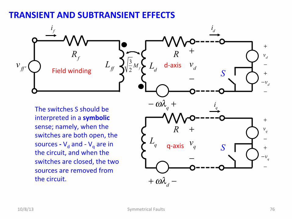
The switches S should be interpreted in a symbolic sense; namely, when the switches are both open, the sources -‐ Vd and -‐ Vq are in the circuit, and when the switches are closed, the two sources are removed from the circuit.
S
i f
Ldd-‐axis
q-‐axis
Field winding
TRANSIENT AND SUBTRANSIENT EFFECTS Since the model is linear we now use superposiDon. Assume that the rotor speed ω remains at its pre-‐fault steady-‐state value. With both switches closed we have the steady-‐state operaDon of the machine since the added sources vd and vq do nothing. Suddenly opening the switches adds the series voltage sources – vd and – vq producing the required short circuits. Thus, the sources – vd and – vq determine the instantaneous changes from the steady state due to the sudden short-‐circuit fault.
10/8/13 Symmetrical Faults 77
TRANSIENT AND SUBTRANSIENT EFFECTS We can calculate the fault-‐induced changes of all variables by sewng the external sources vff, vd and vq equal to zero and suddenly applying the voltages – vd and – vq to the unexcited rotaDng machine, as shown in the next slide. The internal speed voltages ωλq and ωλd are iniDally zero because flux linkages with all coils are zero in the (next) figure before applying the voltages – vd and – vq.
10/8/13 Symmetrical Faults 78

TRANSIENT AND SUBTRANSIENT EFFECTS
10/8/13 Symmetrical Faults 79
v f ′f = 0
Rf
Lff
32
M f
id
iq
−ωλq+ = 0
+ωλd− = 0
Lq
R
R
+−vd
−
+−vq
−
i f
t = 0
t = 0
Ldd-‐axis
q-‐axis
Field winding
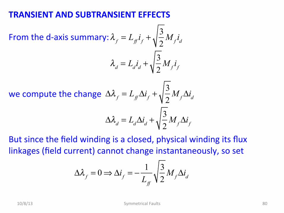
TRANSIENT AND SUBTRANSIENT EFFECTS From the d-‐axis summary: we compute the change But since the field winding is a closed, physical winding its flux linkages (field current) cannot change instantaneously, so set
10/8/13 Symmetrical Faults 80
Δλ f = Lff Δi f +32
M f Δid
Δλd = LdΔid +32
M f Δi f
λ f = Lff i f +32
M f id
λd = Ldid +32
M f if
Δλ f = 0⇒Δi f = − 1
Lff
32
M f Δid
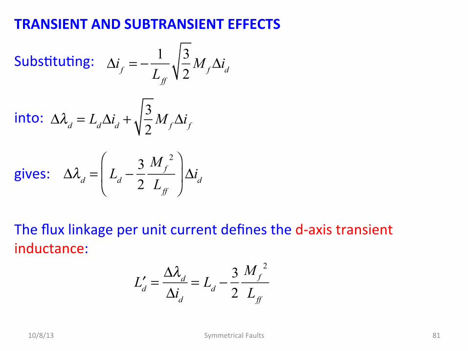
TRANSIENT AND SUBTRANSIENT EFFECTS SubsDtuDng: into: gives: The flux linkage per unit current defines the d-‐axis transient inductance:
10/8/13 Symmetrical Faults 81
Δλd = Ld −
32
M f2
Lff
⎛
⎝⎜
⎞
⎠⎟ Δid
Δi f = − 1
Lff
32
M f Δid
Δλd = LdΔid +
32
M f Δi f
′Ld =
Δλd
Δid
= Ld −32
M f2
Lff

TRANSIENT AND SUBTRANSIENT EFFECTS The d-‐axis transient inductance: Since the direct-‐axis transient reactance X’d = ωL’d is always less than the direct-‐axis synchronous reactance Xd = ωLd. Thus, following abrupt changes at its terminals, the synchronous machine reflects in its armature a transient reactance which is less than its steady-‐state reactance.
10/8/13 Symmetrical Faults 82
′Ld = Ld −
32
M f2
Lff
32
M f2
Lff
> 0

TRANSIENT AND SUBTRANSIENT EFFECTS – Further Considera^ons In defining X’d, we assume that the field is the only physical rotor winding. As previously menDoned, most salient-‐pole machines of pracDcal importance have damper windings consisDng of shorted copper bars through the pole faces of the rotor; and even in a round-‐rotor machine, under short-‐circuit condiDons eddy currents are induced in the solid rotor as if in damper windings. The effects of the eddy-‐current damping circuits are represented by direct-‐axis and quadrature-‐axis closed coils, which are treated in very much the same way as the field winding except that they have no applied voltage.
10/8/13 Symmetrical Faults 83
TRANSIENT AND SUBTRANSIENT EFFECTS – Further Considera^ons To account for the addiDon of damper windings, we need only add to our model the closed D-‐circuit and Q-‐circuit shown on the next slide, which have self-‐inductances LD and LQ and mutual inductances with the other windings as shown. In the steady state the flux linkages are constant between all circuits on the same rotor axis. The D-‐ and Q-‐circuits are then passive (having neither induced nor applied voltages) and do not enter into steady-‐state analysis.
10/8/13 Symmetrical Faults 84

TRANSIENT AND SUBTRANSIENT EFFECTS – Further Considera^ons
10/8/13 Symmetrical Faults 85
d-‐axis
q-‐axis
Field winding
D-‐damper winding
Q-‐damper winding
+v f ′f
−
Rf
Lff
32
M f id
iq
−ωλq +
+ωλd −
Lq
R
R
+vd
−
+vq
−
i f
Ld
32
MQ
RD
RQ
LD
LQ
M R
32
M D iD
iQ
+vD = 0
−
+vQ = 0
−
TRANSIENT AND SUBTRANSIENT EFFECTS – Further Considera^ons Under short-‐circuit condiDons, however, we can determine from the iniDal d-‐axis flux-‐ linkage changes resulDng from sudden shorDng of the synchronous machine with damper-‐winding effects. The procedure is the same as already discussed. The field and D-‐damper circuits represenDng closed physical windings are mutually coupled to each other and to the d-‐coil represenDng the armature along the direct axis. There cannot be sudden change in the flux linkages of the closed windings, and so we can write the flux-‐linkage changes along the d-‐axis by modifying our earlier results as follows:
10/8/13 Symmetrical Faults 86

TRANSIENT AND SUBTRANSIENT EFFECTS – Further Considera^ons Note how these are similar to our previous equaDons but have extra terms because of the addiDonal self-‐ and mutual inductances associated with the D-‐damper circuit.
10/8/13 Symmetrical Faults 87
Δλ f = Lff Δi f +32
M f Δid + MrΔiD = 0
Δλd = LdΔid +32
M f Δi f +32
M DΔiD
ΔλD = 32
M DΔid + M RΔi f + LDΔiD = 0

TRANSIENT AND SUBTRANSIENT EFFECTS – Further Considera^ons Solving: and subsDtuDng: This is the direct-‐axis sub-‐transient inductance. A similar inductance can be defined for the q-‐axis.
10/8/13 Symmetrical Faults 88
Δλd
Δid
= ′′Ld = Ld −32
M f2LD + M D
2Lff − 2M f Mr M D
Lff LD − Mr2
⎡
⎣⎢⎢
⎤
⎦⎥⎥
Δi f = −
32
M f LD − 32
Mr M D
Lff LD − Mr2 Δid
ΔiD = −
32
M D Lff −32
Mr M f
Lff LD − Mr2 Δid
TRANSIENT AND SUBTRANSIENT EFFECTS – Further Considera^ons The direct-‐axis sub-‐transient reactance is X’’d = ωL’’d X’’d is considerably smaller than X’d, hence X’’d < X’d < Xd We have shown that the synchronous machine has different reactances when it is subjected to short-‐circuit faults at its terminals. Immediately upon occurrence of the short circuit, the armature of the machine behaves with an effecDve reactance X’’d, which combines with an effecDve resistance determined by the damping circuits to define a direct-‐axis, short-‐circuit sub-‐transient Dme constant T’’d, typically in the range of 0.03 seconds.
10/8/13 Symmetrical Faults 89
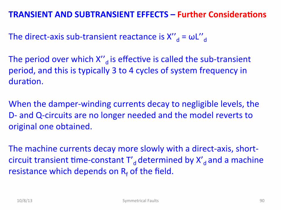
TRANSIENT AND SUBTRANSIENT EFFECTS – Further Considera^ons The direct-‐axis sub-‐transient reactance is X’’d = ωL’’d The period over which X’’d is effecDve is called the sub-‐transient period, and this is typically 3 to 4 cycles of system frequency in duraDon. When the damper-‐winding currents decay to negligible levels, the D-‐ and Q-‐circuits are no longer needed and the model reverts to original one obtained. The machine currents decay more slowly with a direct-‐axis, short-‐circuit transient Dme-‐constant T’d determined by X’d and a machine resistance which depends on Rf of the field.
10/8/13 Symmetrical Faults 90

TRANSIENT AND SUBTRANSIENT EFFECTS – Further Considera^ons The period of effecDveness of X’d is called the transient period and T’d is of the order of 1 second. Finally , for sustained steady-‐state condiDons the d-‐ and q-‐axis reactances Xd = ωLd and Xq = ωLq determine the performance of the saient-‐pole machine, just as the synchronous reactance Xd applies to the round-‐rotor synchronous machine in the steady state. The various reactances are supplied by the machine manufacturers.
10/8/13 Symmetrical Faults 91
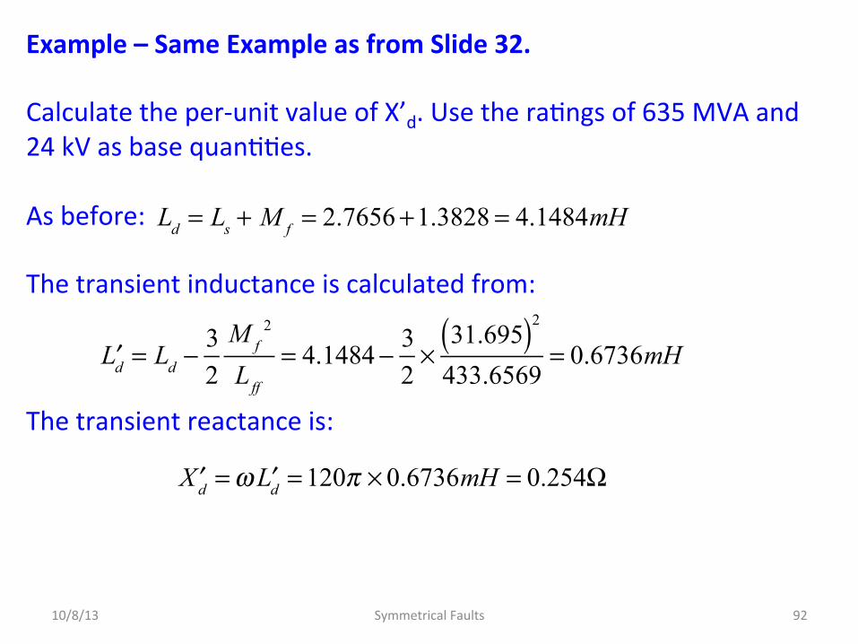
Example – Same Example as from Slide 32. Calculate the per-‐unit value of X’d. Use the raDngs of 635 MVA and 24 kV as base quanDDes. As before: The transient inductance is calculated from: The transient reactance is:
10/8/13 Symmetrical Faults 92
′Ld = Ld −
32
M f2
Lff
= 4.1484− 32×
31.695( )2
433.6569= 0.6736mH
Ld = Ls + M f = 2.7656+1.3828 = 4.1484mH
′Xd =ω ′Ld = 120π × 0.6736mH = 0.254Ω

Example – Same Example as from Slide 33. The impedance base on the machine raDngs is Thus: Note: Hence
10/8/13 Symmetrical Faults 93
Zbase =
Vbase2
VIbase
= 242
635= 0.907Ω
′Xd =
0.2540.907
= 0.28 per − unit
Xd =ωLd = 120π × 4.1484mH = 1.5639Ω⇒1.72 per − unit
′Xd Xd

Short-‐Circuit Currents As seen in the beginning, when an ac voltage is applied suddenly across a series R-‐L circuit the current generally has two components:
a dc component, which decays according to the Dme constant L/R of the circuit, and a steady-‐state sinusoidally varying component of constant amplitude.
A similar but more complex phenomenon occurs when a short circuit appears suddenly across the terminals of a synchronous machine. We have the model – do the short-‐circuit analysis.
10/8/13 Symmetrical Faults 94

Short-‐Circuit Currents The resulDng phase currents in the machine will have dc components, which cause them to be offset or asymmetrical when ployed as a funcDon of Dme as we have seen. We generally neglect the dc-‐components of the currents. If we were to examine the current in one of the phases we would find that the ac-‐component varied as: We see the influence of the transient and sub-‐transient reactances.
10/8/13 Symmetrical Faults 95
i t( ) = 2 Ei cosωt 1
Xd
+ 1′Xd
− 1Xd
⎛
⎝⎜⎞
⎠⎟e−t ′Td + 1
′′Xd
− 1′Xd
⎛
⎝⎜⎞
⎠⎟e−t ′′Td
⎡
⎣⎢⎢
⎤
⎦⎥⎥

TRANSIENT AND SUBTRANSIENT EFFECTS
10/8/13 Symmetrical Faults 96
2 Ei cosωtXd
e−t ′′Td e
−t ′Td
2 Ei cosωtXd
Time t = 0 Short occurs at t = 0.
i t( )
a
b
c
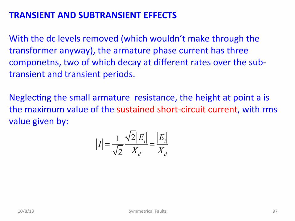
TRANSIENT AND SUBTRANSIENT EFFECTS With the dc levels removed (which wouldn’t make through the transformer anyway), the armature phase current has three componetns, two of which decay at different rates over the sub-‐transient and transient periods. NeglecDng the small armature resistance, the height at point a is the maximum value of the sustained short-‐circuit current, with rms value given by:
10/8/13 Symmetrical Faults 97
I = 1
2
2 Ei
Xd
=Ei
Xd

TRANSIENT AND SUBTRANSIENT EFFECTS If the envelope of the current wave is extended back to zero Dme and the first few cycles where the falloff is very rapid were neglected, the intercept is at height b. The rms value of this current is known as the transient current: Similarly, the rms value of the current whose height is at c is known as the sub-‐transient current:
10/8/13 Symmetrical Faults 98
′I =
Ei
′Xd
′′I =
Ei
′′Xd
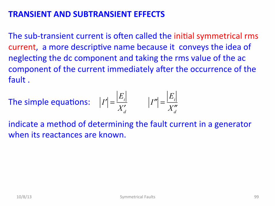
TRANSIENT AND SUBTRANSIENT EFFECTS The sub-‐transient current is oMen called the iniDal symmetrical rms current, a more descripDve name because it conveys the idea of neglecDng the dc component and taking the rms value of the ac component of the current immediately aMer the occurrence of the fault . The simple equaDons: indicate a method of determining the fault current in a generator when its reactances are known.
10/8/13 Symmetrical Faults 99
′I =
Ei
′Xd ′′I =
Ei
′′Xd

TRANSIENT AND SUBTRANSIENT EFFECTS If the generator is unloaded when the fault occurs, the machine is represented by the no-‐load voltage to neutral in series with the proper reactance:
10/8/13 Symmetrical Faults 100
j ′′Xd
± Ei ± Ei ± Ei
j ′Xd jXd
Used to calculate currents for sub-‐transient condiDons.
Used to calculate currents for transient condiDons.
Used to calculate currents for steady-‐state condiDons.
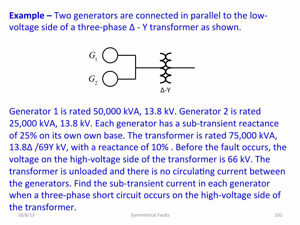
Example – Two generators are connected in parallel to the low-‐voltage side of a three-‐phase Δ -‐ Y transformer as shown. Generator 1 is rated 50,000 kVA, 13.8 kV. Generator 2 is rated 25,000 kVA, 13.8 kV. Each generator has a sub-‐transient reactance of 25% on its own own base. The transformer is rated 75,000 kVA, 13.8Δ /69Y kV, with a reactance of 10% . Before the fault occurs, the voltage on the high-‐voltage side of the transformer is 66 kV. The transformer is unloaded and there is no circulaDng current between the generators. Find the sub-‐transient current in each generator when a three-‐phase short circuit occurs on the high-‐voltage side of the transformer.
10/8/13 Symmetrical Faults 101
G1
G2Δ-‐Y

Example Select 69 kV, 75,000 kVA as the base in the high-‐voltage circuit. Then, the base voltage on the low-‐voltage side is 13.8 kV. For Generator 1:
Note: How did I get this?
10/8/13 Symmetrical Faults 102
′′Xd1 = 0.25× 75,000
50,000= 0.365 p.u.
G1
G2Δ-‐Y
50,000 kVA 13.8 kV
25,000 kVA 13.8 kV 75,000 kVA
13.8Δ /69Y kV
VABase = 75,000 kVA VBase = 69 kV
VABase = 75,000 kVA VBase = 13.8 kV
Ei1
= Ei2= 66
69= 0.957 p.u.
Z p.u. = Zrated
Vrated
Vbase
⎛
⎝⎜⎞
⎠⎟
2VABase
VArated
.
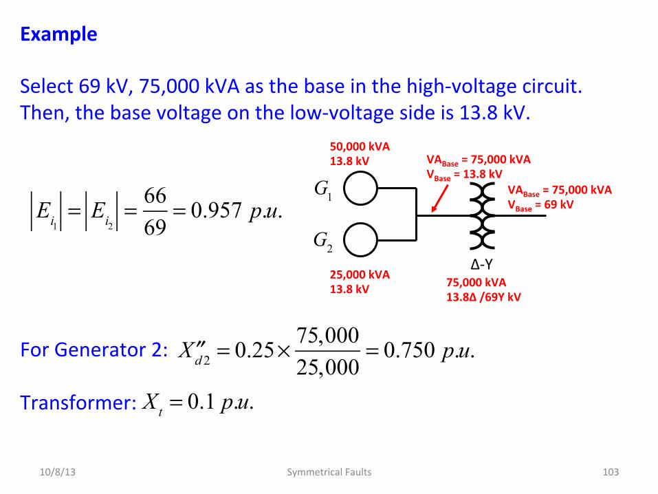
Example Select 69 kV, 75,000 kVA as the base in the high-‐voltage circuit. Then, the base voltage on the low-‐voltage side is 13.8 kV. For Generator 2: Transformer:
10/8/13 Symmetrical Faults 103
′′Xd 2 = 0.25× 75,000
25,000= 0.750 p.u.
G1
G2Δ-‐Y
50,000 kVA 13.8 kV
25,000 kVA 13.8 kV 75,000 kVA
13.8Δ /69Y kV
VABase = 75,000 kVA VBase = 69 kV
VABase = 75,000 kVA VBase = 13.8 kV
Ei1
= Ei2= 66
69= 0.957 p.u.
Xt = 0.1 p.u.

Example Pictured below is the reactance diagram before the fault. A three-‐phase fault is simulated by closing the switch. The internal voltages of the two machines may be considered to be in parallel since they are idenDcal in magnitude and phase and no circulaDng current flows between them.
10/8/13 Symmetrical Faults 104
G1
G2
S j ′′Xd 2 = j0.75
jXt = j0.1 j ′′Xd1 = j0.375
P (fault) Ei1
Ei2
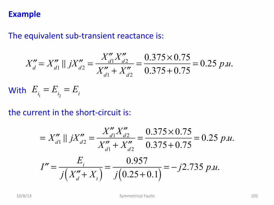
Example The equivalent sub-‐transient reactance is: With the current in the short-‐circuit is:
10/8/13 Symmetrical Faults 105
′′Xd = ′′Xd1 j ′′Xd 2 =
′′Xd1 ′′Xd 2
′′Xd1 + ′′Xd 2
= 0.375× 0.750.375+ 0.75
= 0.25 p.u.
Ei1
= Ei2= Ei
= ′′Xd1 j ′′Xd 2 =′′Xd1 ′′Xd 2
′′Xd1 + ′′Xd 2
= 0.375× 0.750.375+ 0.75
= 0.25 p.u.
′′I =Ei
j ′′Xd + Xt( ) =0.957
j 0.25+ 0.1( ) = − j2.735 p.u.
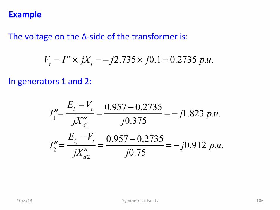
Example The voltage on the Δ-‐side of the transformer is: In generators 1 and 2:
10/8/13 Symmetrical Faults 106
Vt = ′′I × jXt = − j2.735× j0.1= 0.2735 p.u.
′′I1 =Ei1
−Vt
j ′′Xd1
= 0.957 − 0.2735j0.375
= − j1.823 p.u.
′′I2 =Ei2
−Vt
j ′′Xd 2
= 0.957 − 0.2735j0.75
= − j0.912 p.u.

Summary The steady-‐state performance of the synchronous machine relies on the concept of synchronous reactance Xd, which is the basis of the steady-‐state equivalent circuit of the machine. Transient analysis of the synchronous generator requires a two-‐axis machine model. We have seen that the corresponding equaDons involving physical a-‐b-‐c phase variables can be simplified by Park’s transformaDon, which introduces d,q,0 currents, voltages, and flux linkages. Simplified equivalent circuits which follow from the d-‐q-‐0 equaDons of the machine allow definiDons of the subtransient reactance Xd” and transient reactance Xd’. The transient reactance is also important for system stability analysis.
10/8/13 Symmetrical Faults 107

Power Systems Three-‐Phase Short Circuits AssumpDons made to calculate the sub-‐transient fault current for a three-‐phase short circuit in a power system: 1. Transformers are represented by their leakage reactances.
Winding resistances, shunt admiyances, and Δ–Y phase shiMs are neglected.
2. Transmission lines are represented by their equivalent series reactances. Series resistances and shunt admiyances are neglected.
3. Synchronous machines are represented by constant-‐voltage sources behind subtransient reactances. Armature resistance, saliency, and saturaDon are neglected.
10/8/13 Symmetrical Faults 108

Power Systems Three-‐Phase Short Circuits These assumpDons are made for simplicity, and may not always apply. For example, in distribuDon systems, the resistances of primary and secondary distribuDon lines may in some cases significantly reduce fault current magnitudes. Saliency: The word saliency is used as a short expression for the fact that the rotor of a synchronous machine has different electric and magneDc properDes on two axes 90o apart; the direct axis, or axis of symmetry of a field pole, and the quadrature axis, or axis of symmetry midway between two field poles. This difference between the two axes is present not only in salient-‐pole machines but also, to a lesser extent, in round-‐rotor machines, because of the presence of the field winding on the direct axis only.
10/8/13 Symmetrical Faults 109

Power Systems Three-‐Phase Short Circuits Consider a generator that is loaded when a fault occurs. Pre-‐Fault Model If a three-‐phase short circuit fault occurs from P to neutral, the equivalent circuit shown above does not saDsfy the condiDons for calculaDng sub-‐transient current.
10/8/13 Symmetrical Faults 110
+Eg
−
Zext
ZL
jXdg
+
Vt
−
IL
+
VL =Vf
−
Pre-‐fault current
Terminal voltage
No-‐Load voltage
Synchronous reactance
Fault loca^on P
Neutral
This is a steady-‐state model. It does not capture transient behavior.

Power Systems Three-‐Phase Short Circuits AMer the fault occurs, here is the correct circuit:
Fault Model
10/8/13 Symmetrical Faults 111
+′′Eg
−
Zext
ZL
j ′′Xdg
+
Vt
−
IL
+
Vf
−
S
Neutral
P
′′Eg =Vt + j ′′Xdg IL =Vf + Zext + j ′′Xdg( ) IL

Power Systems Three-‐Phase Short Circuits With the switch open: This equaDons defines E’’g, the sub-‐transient internal voltage, is used to calculate the subtransient current I’’. Similarly, to calculate the transient current I’, it must be supplied through the transient reactance X’dg and the transient internal voltage E’g:
10/8/13 Symmetrical Faults 112
′′Eg =Vt + j ′′Xdg IL =Vf + Zext + j ′′Xdg( ) IL
′Eg =Vt + j ′Xdg IL =Vf + Zext + j ′Xdg( ) IL

Power Systems Three-‐Phase Short Circuits Thus, the value of the load current IL determines the values of the voltages E’’g and E’g, which are both equal to the no-‐load voltage Eg only when IL is zero so that Eg is then equal to Vt. It is important to note that the parDcular value of E’’g in series with X’’g represents the generator immediately before and immediately aMer the fault occurs only if the prefault current in the generator has the corresponding value of IL. On the other hand, Eg in series with the synchronous reactance Xdg is the equivalent circuit of the machine under steady-‐state condiDons for any value of the load current. The magnitude of Eg is determined by the field current of the machine, and so for a different value of IL in the pre-‐fault circuit lEgI would remain the same but a new value of E’’g would be required.
10/8/13 Symmetrical Faults 113

Power Systems Three-‐Phase Short Circuits Synchronous motors have reactances of the same type as generators. When a motor is short-‐circuited, it no longer receives electric energy from the power line, but its field remains energized and the inerDa of its rotor and connected load keeps it rotaDng for a short period of Dme.
10/8/13 Symmetrical Faults 114
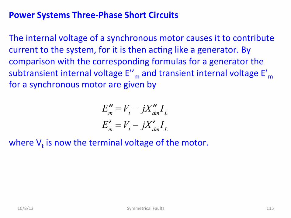
Power Systems Three-‐Phase Short Circuits The internal voltage of a synchronous motor causes it to contribute current to the system, for it is then acDng like a generator. By comparison with the corresponding formulas for a generator the subtransient internal voltage E’’m and transient internal voltage E’m for a synchronous motor are given by where Vt is now the terminal voltage of the motor.
10/8/13 Symmetrical Faults 115
′′Em =Vt − j ′′XdmIL
′Em =Vt − j ′XdmIL
Power Systems Three-‐Phase Short Circuits Fault currents in systems containing generators and motors under load may be solved in one of two ways: 1. by calculaDng the subtransient (or transient) internal voltages of
the machines or 2. by using Thévenin's theorem. An example will illustrate.
10/8/13 Symmetrical Faults 116
Power Systems Three-‐Phase Short Circuits Suppose that a synchronous generator is connected to a synchronous motor by a line of external impedance Zext. The motor is drawing load current IL from the generator when a symmetrical three-‐phase fault occurs at the motor terminals. The equivalent circuits and current flows of the system immediately before and immediately aMer the fault occurs are…
10/8/13 Symmetrical Faults 117

Power Systems Three-‐Phase Short Circuits Before the Fault:
10/8/13 Symmetrical Faults 118
Zext
+
Vt
−
IL
+
Vf
−
Neutral
P
+′′Eg
−
j ′′Xdg j ′′Xdm
+′′Em
−

Power Systems Three-‐Phase Short Circuits A\er the Fault:
10/8/13 Symmetrical Faults 119
+′′Eg
−
Zext
j ′′Xdg
+
Vt
−
′′Ig
+
Vf
−
j ′′Xdm
+′′Em
−
Neutral
′′Im
I '' f
P

Power Systems Three-‐Phase Short Circuits By replacing the synchronous reactances of the machines by their subtransient reactances, we calculate the subtransient internal voltages of the machine immediately before the fault occurs using our earlier results (Slide 113 and 116): Now from the faulted circuit:
10/8/13 Symmetrical Faults 120
′′Ig =′′Eg
Zext + j ′′Xdg
=Vf + Zext + j ′′Xdg( ) IL
Zext + j ′′Xdg
=Vf
Zext + j ′′Xdg
+ IL
′′Im =′′Em
j ′′Xdg
=Vf − j ′′Xdg IL
j ′′Xdg
=Vf
j ′′Xdg
− IL
′′Eg =Vf + j ′′Xdg IL =Vf + Zext + j ′′Xdg( ) IL
′′Em =Vf − j ′′Xdg IL

Power Systems Three-‐Phase Short Circuits Adding: Note that the fault current does not include the pre-‐fault current, i.e., the load current – an important observaDon. Again, Vf is the pre-‐fault voltage at the fault point.
10/8/13 Symmetrical Faults 121
′′I f = ′′Ig + ′′Im
=Vf
Zext + j ′′Xdg
+ IL +Vf
j ′′Xdm
− IL
=Vf
Zext + j ′′Xdg
+Vf
j ′′Xdm
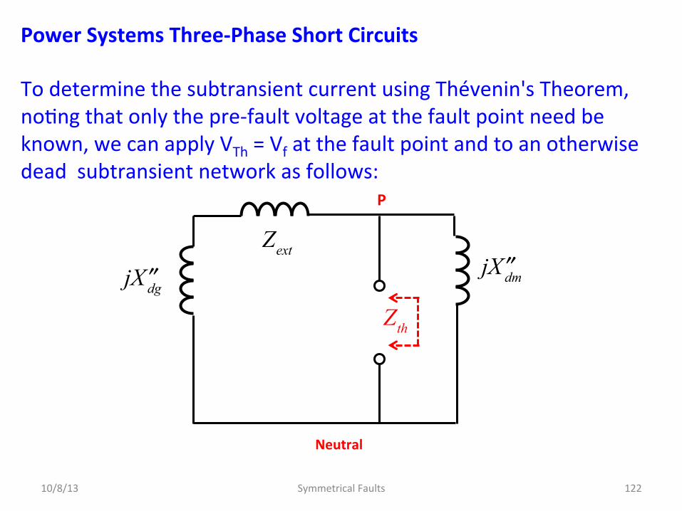
Power Systems Three-‐Phase Short Circuits To determine the subtransient current using Thévenin's Theorem, noDng that only the pre-‐fault voltage at the fault point need be known, we can apply VTh = Vf at the fault point and to an otherwise dead subtransient network as follows:
10/8/13 Symmetrical Faults 122
j ′′Xdg j ′′Xdm
Neutral
P
Zext
Zth
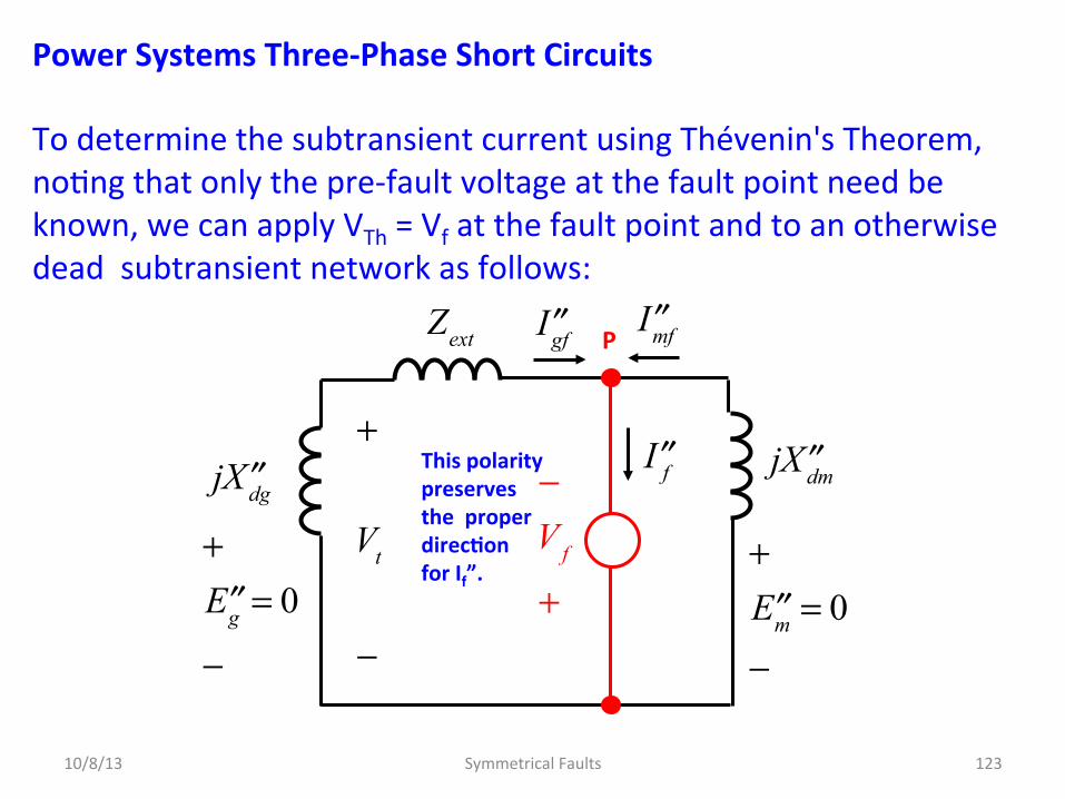
Power Systems Three-‐Phase Short Circuits To determine the subtransient current using Thévenin's Theorem, noDng that only the pre-‐fault voltage at the fault point need be known, we can apply VTh = Vf at the fault point and to an otherwise dead subtransient network as follows:
10/8/13 Symmetrical Faults 123
+′′Eg = 0
−
Zext
j ′′Xdg
+
Vt
−
′′Igf
−Vf
+
j ′′Xdm
+′′Em = 0
−
′′Imf
′′I f
P
This polarity preserves the proper direc^on for If”.
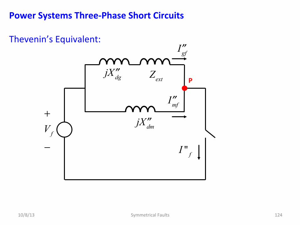
Power Systems Three-‐Phase Short Circuits Thevenin’s Equivalent:
10/8/13 Symmetrical Faults 124
Zext
+Vf
− I '' f
P
′′Igf
j ′′Xdm
′′Imf
j ′′Xdg

Power Systems Three-‐Phase Short Circuits
10/8/13 Symmetrical Faults 125
ZTh = Zext + j ′′Xdg( ) || jX ''dm
=j ′′Xdm Zext + j ′′Xdg( )Zext + j ′′Xdg( ) + j ′′Xdm
′′I f =Vf
ZTh
=Vf
Zext + j ′′Xdm + ′′Xdg( )j ′′Xdm Zext + j ′′Xdg( )

Example: A synchronous generator and motor are rated 30,000 kVA, 13.2 kV, and both have subtransient reactances of 20%. The line connecDng them has a reactance of 10% on the base of the machine raDngs. The motor is drawing 20,000 kW at 0.8 power-‐factor leading and a terminal voltage of 12.6 kV when a symmetrical three-‐phase fault occurs at the motor terminals. Find the subtransient currents in the generator, the motor, and the fault by using the internal voltages of the machine.
10/8/13 Symmetrical Faults 126

Example: SoluDon
10/8/13 Symmetrical Faults 127
Example: SoluDon
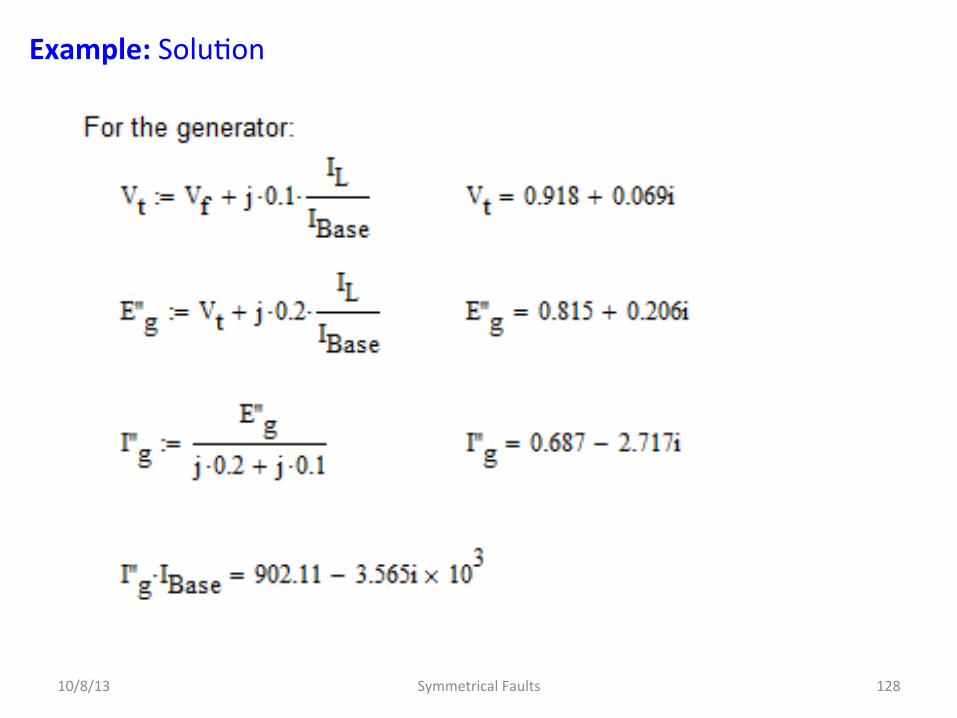
10/8/13 Symmetrical Faults 128

Example: SoluDon
10/8/13 Symmetrical Faults 129

Example: SoluDon (via Thevenin’s Theorem)
10/8/13 Symmetrical Faults 130

Example: Remember, the total current is the transient response plus the steady-‐state response, hence:
10/8/13 Symmetrical Faults 131
′′Ig = ′′Igf + IL
′′Im = ′′Imf − IL

Example: Usually, load current is omiyed in determining the current in each line upon occurrence of a fault. In the Thévenin method neglect of load current means that the prefault current in each line is not added to the component of current flowing toward the fault in the line. The previous example neglects load current if the subtransient internal voltages of all machines are assumed equal to the voltage Vf at the fault before the fault occurs, for such is the case if no current flows anywhere in the network prior to the fault. More on this later…
10/8/13 Symmetrical Faults 132
Example: Resistances, charging capacitances, and off-‐nominal tap-‐changing of transformers are also usually omiyed in fault studies since they are not likely to influence the level of fault current significantly. CalculaDon of the fault current is thus simplified since the network model becomes an interconnecDon of inducDve reactances and all currents throughout the faulted system are in-‐phase, as the Thevenin example demonstrated.
10/8/13 Symmetrical Faults 133
What About More Complicated Networks? We first need to consider some aspects of Network CalculaDons
10/8/13 Symmetrical Faults 134