sxc sxd ami - golz uk drill motor.pdf · the beluga sxc / sxd represent a whole new generation of...
TRANSCRIPT

DR. BENDER GmbH Innovative Power Tools Operating Manual Drive unit Beluga sXc / SXD
HF III Issued 11.2015 Subject to change
All rights reserved
DR. BENDER GmbH • D-75382 Althengstett • Tel 07051-9291-0 • Fax 07051-9291-91 We are on the internet at http://www.dr-bender.de • eMail: [email protected]
2
Declaration of conformity
DR.BENDER GmbH Innovative Power Tools
EC – Declaration of conformity for machines (EG-RL 2006/42/EG) Herewith, the manufacturer,
Dr. BENDER GmbH Industriestrasse 22 75382 Althengstett
declares that the machine
BELUGA SXC / SCBELUGA SXC / SCBELUGA SXC / SCBELUGA SXC / SCDDDD
conforms with the aforementioned Directive and the following Directives
- Machinery Directive of the European Parliament and Council (EC-RL 2006/42/EC) - Electromagnetic compatibility (EMC) (2004/108/EC) - Low Voltage Directive (2006/95/EC)
The following harmonised standards have been used for assessment of the appliance:
EN 50144-1 EN 50144-2-1 EN 55014-1 EN 61000-3-2 EN 61000-3-3 EN 55014-2 EN 61029-1
The person authorized to compile the relevant technical documentation is: Bernhard Brehm c/o Dr. BENDER GmbH
Industriestrasse 22 75382 Althengstett
Germany DR.BENDER GmbH Althengstett, 25.11.2015 Industriestraße 22 D-75382 Althengstett Tel. 07051/9291-0, Fax 07051/9291-91
B. Brehm, Managing Director
This Declaration does not constitute a warranty of properties. The safety instructions in the supplied product documentation must be followed.
3
Contents Page Declaration of conformity 2 Contents 3 1.0 Symbol and pictogram description 4 1.1 Function description 6 2.0 General instructions 7 2.1 Technical description 7 2.2 Applications 7 2.3 Safety 8 3.0 Transport and storage 8 3.1 Transport 8 3.2 Storage 8 4.0 Main dimensions and technical data 9 4.1 Dimensions 9 4.1.1 Beluga SXC 9 4.1.2 Beluga SXD 9 4.2 Technical data 10 4.2.1 Beluga SXC 10 4.2.2 Beluga SXD 10 4.3 Noise emission and vibration [EN 50144] 10 4.4 Operating temperatures 10 5.0 Commissioning 11 5.1 Mains connection 11 5.2 Water connection 11 5.3 Operation panel 12 5.4 Drill bits 13 6.0 Safety instructions 13 7.0 Repair and maintenance 13 7.1 Daily maintenance 13 7.2 Service after approx. 120 operating hours 14 7.3 Quarterly 14 8.0 Speed setting depending on cutting speed 14 9.0 Warranty 14 10.0 General Safety Instructions 14 11.0 Spare parts lists 15 11.1 Driving machine SXC 15 11.2 Driving machine SXD 16 11.3 Motor complete SXC 18 11.4 Motor complete SXD 20 11.5 Gear complete 22

4
Attention The safety instructions included in this operating manual must be followed! Custom models and design variants may deviate from the basic type in technical details. In the event of any discrepancie s, we recommend that you
contact DR.BENDER GmbH urgently. Always give the ma chine type and machine number in any correspondence. 1.0 Symbol and pictogram description
Attention Indicates instructions may endanger your health or the functionality of the unit if they are not followed. The warranty shall become null and void if you cause defects to the unit by non-compliance with these instructions.
Attention Warning: high voltage. Prior to service, the system have to be disconnected from power source and secured against reconnection. Electric shocks can cause seriously or lethal injuries.
Recycling Please recycle waste.
Disposal For recycling, please follow national laws.

5
Safety signs on the unit
Wear safety shoes
Wear protective gloves
Wear protective helmet
Wear protective goggles
Wear ear protection
Wear respiratory mask
Disconnect power before working
Read instructions

6
1.1 Function description
Drill spindle 1 ¼“ UNC
Drill spindle 1 ¼“ UNC
Switch box
Nameplate
Mains connection
beluga SX D
Nameplate
Water connection
Beluga SXC
Base
Switch box halves
Mains connection
Base
Operation panel
Air inlet
Water connection

7
2.0 General instruction 2.1 Technical description The BELUGA SXC / SXD represent a whole new generation of drive units for stone cutting. The excep-tionally comprehensive modular system offers the flexibility needed today when performing cutting work in concrete and stone. To achieve this, newly developed high-frequency motor parts are used in the motor. The frequency range is controlled by the frequency converter from 0 - 1000 Hz integrated into the Power-box. At 1000 Hz, the rotor reaches a speed of 30.000 min-1. A major benefit lies in the exceptional weight / power ratio (motor power output = 12 kW / weight = 8.2 kg -> 1.4). Using conventional technology e.g. type BBM33extra (motor power output = 2.4 kW / weight = 13.5 kg -> 0.17) It means that the weight of the ma-chine has been reduced sevenfold using the high frequency technology. We have succeeded in running the Powerbox as well as the drive units on a 230V single phase network or on a 400 V three-phase network. This means that only one piece of equipment is needed for use on both voltage sources. Further benefits lie in the stepless speed control. This enables the best speed to be assigned to each tool diameter, in order to attain the best possible cutting speed on the tool. During work, the speed can be steplessly reduced if you come up against steel reinforcements and thus can be optimised according to the progress of the work. Here, you can run the unit at much higher cutting speeds (Attention! depends on the tool) and in doing so, the progress of the job can be speeded up by up to 150%. With conventional machines, the torque drops very sharply at the higher speeds. Therefore, this advantage does not apply to conventional machines. 2.2 Applications The drill motors BELUGA SXC / SXD and the related Powerboxes can be used according to the data attached to the information plate. When you are using custom-built machines, the details on the quotation and the order confirmation also apply. . The drive units and the Powerboxes are essentially Class I appliances, only this guarantees the full high-quality protection of the residual current circuit breaker. When suitable saw blades and drill bits are used, a wide range of materials can be cut:
- Concrete (even with strong reinforcement) - Sandstone and limestone - All building materials for solid walls - Asphalt road surfacing
The machines must be connected to the Powerbox RX/SX 12.

8
2.3 Safety
Warning Before commissioning, check that the mains voltage and frequency match the data given on the information plate. ± 5 % voltage and/or ± 2 % frequency deviation are permitted. Repairs may only be perfor med by suitably qualified staff based on their training and experience.
Pay particular attention to: - the technical data and information on the permitted use (commissioning, standard operating
conditions), which are included e.g. in the catalogue, the operating manual, the information plate details, and other product information.
- the relevant accident prevention regulations - the correct use of tools - the use of personal protective equipment
3.0 Transport and storage 3.1 Transport
Warning The drive units must be inspected for transport dam age after receipt. Any damage present must be recorded in writing.
3.2 Storage The storage location should be dry, clean, and at a constant temperature wherever possible. In order that the lubrication film in the bearings and the seal systems does not separate, the drive shaft should be turned several times manually after a lengthy storage period, e.g. at monthly intervals. The roller bearings of the devices should be replaced (or re-lubricated) if the period between delivery and commissioning is more than 4 years. This period will be significantly reduced if the storage conditions are unsuitable.

9
4.0 Main dimensions and technical data 4.1 Dimensions 4.1.1 Beluga SX C 4.1.2 Beluga SX D

10
4.2 Technical data 4.2.1 Beluga SX C Rated voltage 400 3~ / 230 1~ V
Current rating 16 / 16 A
Power consumption 8.000 / 3.700 W
Frequency 50 – 60 Hz
Idle - full load speed continuously variable 0 - 850 min-1
Power output 5.400 / 2.400 W
Torque 180 / 120 Nm
Drilling diameter 40 – 450 mm
Weight 7,8 kg
Core bit connection 1 ¼“ UNC -
Cooling medium air -
4.2.2 Beluga SX D
Rated voltage 430 3~ / 230 1~ V
Current rating 18 / 16 A
Power consumption 12.000 / 3.700 W
Frequency 50 – 60 Hz
Idle - full load speed continuously variable 0 - 850 min-1
Power output 8.200 / 2.400 W
Torque 220 / 120 Nm
Drilling diameter 40 – 450 mm
Weight 8,2 kg
Core bit connection 1 ¼“ UNC -
Cooling medium water -
4.3 Noise emission and vibration [EN 50144]
Sound pressure level Sound power level Vibration dB(A) dB m/s2
83 96 < 2,5
4.4 Operating temperatures
If the system is sufficiently cooled, the Beluga SXD attains to the cooling water temperature. The plas-tic housing of the air cooled Beluga SXC attains temperatures of up to 45°C.

11
5.0 Commisionning
5.1 Mains connection
Attention Check whether the mains voltage matches the voltage given on the information plate. Check whether the mains voltage matches the voltage given on the information plate.
Remove the protective covers on the plug sockets. These protective covers are designed to protect the socket against the ingress of water when the plug is not connected. This significantly increases the service life of the high-quality cable sockets. Connect the electrical power lead of the Beluga drive unit to the round socket located on the front of the Powerbox. Lock the bayonet sleeve of the plug socket until you hear it click, in order to maintain the required IP 67 protection. 5.2 Water connection The water must first flow through the Powerbox, then through the drive unit, and only then to the drill bit. Therefore, connect the water supply to the water line (with tap) provided on the Powerbox. Attention: If possible, do not exceed a maximum water pressure of 3 bar. The Beluga SX D drive motor is water-cooled. During operation, always supply sufficient cold cooling water (cooling water should not exceed 30 °C). The machine must be operated during full load operation with at least 1/2 litre of water per minute. Only use clean tap water, no contaminated or waste water, since otherwise the heat transfer to the cooling surfaces is no longer guaranteed and the motor may suffer irreparable damage. The Powerbox PB RX/SX 12 is normally air-cooled and therefore does not require the water connection. Water supply fittings (part no. 102122) are available as custom accessories. Please take the necessary information from the Powerbox PB RX/SX 12 operating manual.

12
5.3 Bedienung Beluga SXD / SXCBeluga SXD / SXCBeluga SXD / SXCBeluga SXD / SXC
If the Powerbox will be connected to the net, the green LED flashes. This means that the power box is in standby mode. When you turn on the green pushbutton, the power box is switched on. The green LED changes from blinking to a steady light. With the speed control the speed from 0 to 100% can be selected. In the operation with the drilling motors, this value should always be set to 100% to obtain the maximum speed of the drill spindle. The panel of Beluga SXW / SXC now showing Speed 000 min-1 and the green LED is flashing. By pressing the Plus + or minus - button you can change the speed from 0 rpm up to 850 rpm. By pressing the On-Off switch of the drill motor Beluga SXD / SXC will now be accelerated to the preset speed. During the drilling operation can be adjusted at any time-the rotational speed. The power display is mirrored by the Powerbox on the control panel. This is described in detail in the operating instructions of the Powerbox.

13
5.4 Drill bits You can use any drill bit with a connection thread of 1 ¼“ UNC or with a four-hole flange or a six-hole flange. Only use drill bits that are suitable for the stone type. Using only concentric drill bits that are not deformed prolongs the service life of the drive unit. Ensure that the diamond segments have an adequate undercut in relation to the drill bits. 6.0 Safety instructions
Attention The units must be attended when in use. Disconnect the mains plug and check that the switch is disabled,
- when the units remain unattended - during assembly and disassembly - during voltage drop (rated voltage 400 V 3~ under 340 V), (rated voltage 230 V 1~ under 200 V), - if the mains voltage fluctuates (phase imbalance) or during interruption of a phase (phase failure), - when adjusting or fitting an accessory.
Switch the machine off when you stop operation for any reason. This prevents the unit from suddenly starting while unattended. Do not use the unit if,
- a part of the housing is missing or defective, - There is damage to switches, lines, or plug connections (daily inspection!) - when operating the units, cooling water must not penetrate the electrical components in whichever
location the units are used. - If water is dripping from the unit, stop work and take the unit to an authorised service centre. - After a break in operation, only switch on again if the saw blade or drill bit can rotate freely. - Check the work area with a pipe detector in order to avoid cutting into electrical cables, water pipes
or gas pipes etc. 7.0 Repair and maintenance
Warning Always disconnect from the mains before starting re pair or maintenance work. After any repair, the unit must be checked by a qua lified electrician (legal requirement pursuant to VBG4 since 1.1.1990).
7.1 Daily maintenance Check that no water is leaking out of the unit. This may impair the electrical safety of the unit and lead to damage to the gearbox. In this case, please contact an authorised service centre. Visual inspection for damage to the switches, the lines, or the plug sockets. Clean the units after completion of the work. Check that no water gets into the units during cleaning. Drain the cooling water after using the machine. (Open the tap and blow out the water using compressed air). This is particularly important in case of frost formation in winter.

14
7.2 Service after 120 operating hours A service is due after 120 operating hours. The machine counts the operating hours itself and tells you when 120 operating hours are reached by a blue LED on the handle. All worn parts are replaced during this service. The next service is carried out at further intervals of 120 operating hours. The service interval may be extended by max. 10 %, so you can complete your work with the machine at your own convenience. If the maximun service interval of 120 + 12 operating hours is exceeded, the warranty becomes null and void. 7.3 Quarterly Have the cables, switches, plugs checked by a qualified specialist (provision pursuant to VBG4) and record this. Replacing the gearbox oil significantly increases the service life of the gearbox. 8.0 Speed setting depending on cutting speed The drive units of the Beluga series allow stepless speed adjustment. You can thus set the best cutting speed for your drill bit. This also provides a perfect, quick cut and the service life of the tool is also significantly extended. 9.0 Warranty Pursuant to our Terms & Conditions of Sale, we offer a warranty of 12 months from the date of purchase. This covers the free repair of material and production defects which are shown to have been caused prior to sale. An original sales receipt must always be produced when asserting a warranty claim. It must include the full address of the dealer, purchase date, and type code of the product. The user manual for the relevant prod-uct as well as the safety instructions must have been followed. Damage caused by operating errors is not covered by the warranty. The manufacturer’s products are developed and built for specific applications. If the product is used for purposes other than the intended purpose based on the user manual, or in the event of misuse, or if unap-proved accessories are used, the warranty shall become null and void. The products must be regularly maintained and cleaned according to the instructions in the user manual. The warranty shall become null and void in the event of an intervention by third parties (opening the ma-chine). The warranty does not cover maintenance and cleaning work. You must ensure that only original spare parts and accessories are used. The products must be purchased from an authorised dealer. If non-original parts are used, this may result in consequential damage and in-creased risk of accidents. The manufacturer is not liable for such damage. Disassembled, partially disas-sembled units, and units repaired with third party parts are not covered by the warranty. Certain parts are subject to normal wear and tear depending on use. These parts include e.g. carbon brushes, ball bearings, switches, mains cables, seals, etc. These consumable parts are not covered by the warranty. Consumable parts are highlighted in the spare parts lists. 10.0 General Safety instructions The general safety instructions can be found in the supplied safety instruction booklet.

15
11.0 Spare parts lists 11.1 Driving machine SXC
Item Part no. Description No. 1 302189 Driving machine SXC 1 2 302197 Motor complete 1 3 302186 Gear complete 1 4 802463 Water connection complete 1 ** 5 802402 Thread nipple 1 6 802464 Hose 1 ** 7 801801 Ball valve complete 1 8 802465 Nipple 1 9 800040 O ring 1 **
Wearing parts **
16
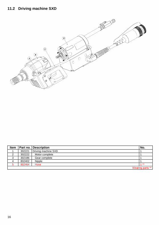
11.2 Driving machine SXD
Item Part no. Description No.
1 302221 Driving machine SXD 1 2 302222 Motor complete 1 3 302186 Gear complete 1 4 802402 Nipple 1 5 802464 Hose 1 **
Wearing parts **

17

18
11.3 Motor complete SXC

19
Item Part no. Description No. 1 302197 Motor complete SX C 1 2 102314 Motor housing 1 3 802022 Stator 1 4 302266 Rotor kompl. 1 5 901370 Groove ball bearing 1 ** 6 900801 Locking ring 1 ** 7 800380 Spring ring 1 8 901138 Shim ring 1 9 901208 Groove ball bearing 1 ** 10 801574 Cup spring 1 11 401768 Distance bush 1 12 802354 Resolver rotor 1 13 102302 Stored cap 1 14 802353 Resolver stator 1 15 800092 O ring 2 ** 16 301941 Cover 1 17 802029 O ring 1 ** 18 802433 Hexagon socket head cap screw with centre hole 4 19 102445 Switch box half left 1 20 803019 Sealing tape 2 21 802713 Keypad 1 22 802792 Passage grommet 1 23 102438 Platine complete 1 24 102357 Switch box half right 1 25 402158 Screw plug 1 26 802744 Counter nut 1 27 803022 O ring 1 ** 28 402037 Air cooler complete 1 29 802303 O ring 1 ** 30 800076 Locking washer 3 31 900719 Hexagon socket head cap screw with centre hole 3 32 900756 Hexagon socket head cap screw with centre hole 4 33 901298 Hexagon socket countersunk head screw 2 34 150549 Hexagon socket countersunk head screw 2 35 802855 Connection cable conf. 1
Wearing parts **

20
11.4 Motor complete SXD

21
Item Part no. Description No. 1 302222 Motor complete SX D 1 2 201015 Motor housing 1 3 802022 Stator 1 4 302266 Rotor complete 1 5 901370 Groove ball bearing 1 ** 6 900801 Locking ring 1 ** 7 800380 Spring ring 1 8 901138 Shim ring 1 9 901208 Groove ball bearing 1 ** 10 801574 Cup spring 1 11 401768 Distance bush 1 12 802354 Resolver rotor 1 13 401892 Flat sealing 1 ** 14 401421 Flat sealing 1 ** 15 802353 Resolver stator 1 16 800092 O ring 2 ** 17 102009 Sleeve 1 18 800100 O ring 1 ** 19 800076 Locking washer 3 20 902026 Hexagon socket head cap screw with centre hole 3 21 102010 stored cap 1 22 800391 Sealing ring 4 ** 23 802197 Hexagon socket head cap screw with centre hole 4 24 900231 Washer 1 25 900181 Wave spring washer 1 26 900412 Slotted pan head screw 1 27 802481 O ring 1 ** 28 201178 Switch box 1 29 102384 Platine complete 1 30 902090 Hexagon socket countersunk head screw 6 31 802402 Nipple 1 32 803017 Connection cable conf. 1 33 402157 Cover plate 1 34 900623 Cross recessed pan head tapping screw 4 35 802713 Keypad 1 36 800359 Water connection complete 1 ** 37 800415 Hose complete 1 38 800028 Sealing ring 2 ** 39 800023 Ball valve complete 1 40 800020 Nipple 1 41 800040 O ring 1 ** 42 802898 Sticker 1 43 802479 Sticker 1
Wearing parts **

22
11.5 Gear complete

23
Item Part no. Description No. 1 302186 Gear complete 1 2 201164 Gear housing 1 3 901139 Groove ball bearing 1 ** 4 900687 Shaft seal 2 ** 5 901354 Shim ring 1 6 302293 Drill spindle complete 1 7 901355 Taper roller bearing 1 ** 8 901202 Shaft seal 1 ** 9 901247 Parallel key 1 10 301597 Counter gear 1 11 901356 Locking plate 1 12 901357 Slotted round nut for hook spanner 1 13 401684 O ring 1 ** 14 302188 Gear V complete 1 15 201189 Housing 1 16 901139 Groove ball bearing 1 ** 17 301385 Pinion shaft 2 1 18 901071 Parallel pin 2 19 302267 Gear 2 slip coupling 1 20 302249 Hub 1 21 401563 Brake disc 4 22 401562 Support washer I 2 23 401339 Plate spring 1 24 401561 Hub 1 25 301252 Support washer A 1 26 401566 Nut 1 27 101866 Pin 1 28 800107 Shim washer 1 29 900209 Snap ring 1 30 800077 Lock washer 6 31 900312 Hexagon socket head cap screw with centre hole 6 32 900708 Shaft seal 1 ** 33 800027 Sealing ring 1 ** 34 800026 Screw plug 1 35 201165 Base 1 36 402135 Angle support 1 37 801379 Button head socket screw 9 38 801736 Button head socket screw 2
Wearing parts **