svu - donaldson company
TRANSCRIPT
SVU
INSTALLATION, OPERATION AND MAINTENANCE MANUAL
DOC-AM06204-01 0620 MASTER LANGUAGE - ENGLISH

Installation, Operation and Maintenance manual
2
SVU

Installation, Operation and Maintenance manual
3
SVU
CONTENTS
TABLE OF CONTENTS ........................................................................................ 3
SAFETY ................................................................................................................ 4
General safety recommendations ............................................................. 4
Maintenance safety ................................................................................... 6
INTRODUCTION .................................................................................................. 7
Product information ................................................................................... 7
Function ..................................................................................................... 7
Specifications ............................................................................................ 8
Component overview ................................................................................ 9
PRIOR TO INSTALLATION ..................................................................................10
Location ....................................................................................................10
Required tools and equipment .................................................................10
Delivery and inspection ............................................................................10
INSTALLATION ...................................................................................................11
Unload and transport of the unit ...............................................................11
Installation of unit .................................................................................... 13
Installation of PowerCore elements ........................................................ 14
Controller ................................................................................................. 16
Electrical connections .........................................................................17
Controller settings .............................................................................. 18
Compressed air connections ................................................................... 20
START-UP CHECKLIST ....................................................................................... 21
OPERATION SCHEDULE ................................................................................... 22
SERVICE ............................................................................................................ 22
TROUBLESHOOTING GUIDE ............................................................................ 22
SUPPLEMENTARY INFORMATION ................................................................... 23
DECLARATION OF CONFORMITY....................................................................A1
Installation, Operation and Maintenance manual
4
SVU
SAFETY
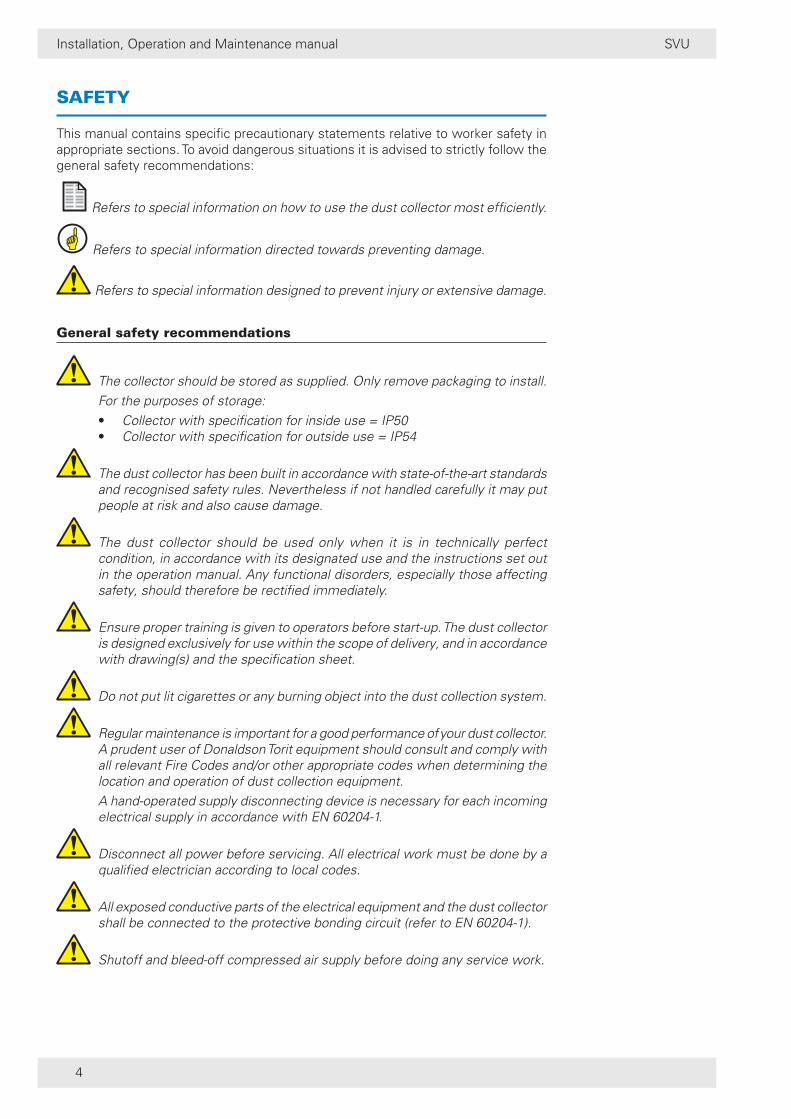
This manual contains specific precautionary statements relative to worker safety in appropriate sections. To avoid dangerous situations it is advised to strictly follow the general safety recommendations:
Refers to special information on how to use the dust collector most efficiently.
Refers to special information directed towards preventing damage.
Refers to special information designed to prevent injury or extensive damage.
General safety recommendations
The collector should be stored as supplied. Only remove packaging to install. For the purposes of storage:
• Collector with specification for inside use = IP50• Collector with specification for outside use = IP54
The dust collector has been built in accordance with state-of-the-art standards and recognised safety rules. Nevertheless if not handled carefully it may put people at risk and also cause damage.
The dust collector should be used only when it is in technically perfect condition, in accordance with its designated use and the instructions set out in the operation manual. Any functional disorders, especially those affecting safety, should therefore be rectified immediately.
Ensure proper training is given to operators before start-up. The dust collector is designed exclusively for use within the scope of delivery, and in accordance with drawing(s) and the specification sheet.
Do not put lit cigarettes or any burning object into the dust collection system.
Regular maintenance is important for a good performance of your dust collector. A prudent user of Donaldson Torit equipment should consult and comply with all relevant Fire Codes and/or other appropriate codes when determining the location and operation of dust collection equipment.
A hand-operated supply disconnecting device is necessary for each incoming electrical supply in accordance with EN 60204-1.
Disconnect all power before servicing. All electrical work must be done by a qualified electrician according to local codes.
All exposed conductive parts of the electrical equipment and the dust collector shall be connected to the protective bonding circuit (refer to EN 60204-1).
Shutoff and bleed-off compressed air supply before doing any service work.

Installation, Operation and Maintenance manual
5
SVU
In each individual case vent design, vent ducts and pressure resistant design are worked out by Donaldson Torit for the specific products, circumstances and environment, and should never be altered unless Donaldson Torit has given explicit admission.
All electrical equipment should be dust explosion proof according to the zoning and surface temperature limitations of the equipment.
The dust collector cannot be used in a potentially explosive atmosphere (according to ATEX directive 2014/34/EU), unless stated otherwise on the nameplate of the unit and the scope of delivery.
The collector should never handle explosive or flammable materials or explosive dusts.
The collector should never be used for products that can cause bacteriological contamination.
The collector should be located at a minimum distance of 10 meter from any heat source to prevent sparks from jumping over.
The user of the dust collector is responsible for disposal of any dust generated by the process, in acoordance with local regulations.
The SVU can not be used as an element for discharging overpressure inside closed volumes. One or more blow-off valves must be provided on the silo to keep the pressure level within the filter resistance limits.
The dust collector will not prevent explosions or overpressure. The Silo Vent Unit is not a pressure relief valve.
The air flow handled by the dust collector must never exceed the value defined in our product specifications.
Using the dust collector when the components (filter elements, cleaning system, etc.) are not in perfect condition can cause personal injuries and/or pollution.
Do not start operating the dust collector before the equipment in which it is to be incorporated has been declared conforming to the relevant national and local legislative provisions in force.
A prudent user of Donaldson Torit dust collectors should:
• Take every possible precaution to prevent a fire or explosion from occurring.
• Consult with their insurance carrier or local authorities regarding the hazardous nature of dust produced.
• Use only authorised replacement parts supplied by Donaldson Torit.• Unless otherwise specified, DO NOT exceed operating pressure
as specified by technical data.• Insure that the operating temperature of the dust collector does not
exceed 60° C.• Refer to guidelines VDI 3673.

Installation, Operation and Maintenance manual
6
SVU
Donaldson will not accept responsibility for safety of persons or objects or operation failure of the SVU if the loading/unloading operations from trucks, transport, positioning at the site, use repairs, maintenance etc. have not been executed in compliance with the warnings described in this manual, and in accordance with the legislation in force.
Always wear gloves when performing maintenance on the SVU. Components of the SVU, in particular the tube sheet, can be hot after silo filling.
Maintenance safety
Personnel cannot perform maintenance on the unit, or open the unit, when windspeeds exceed 19 m/s (≈ 70 km/h).
Before performing any maintenance, make sure the compressed air and the electrical power supply are shut off.
If the dust collector’s original design or the actual process is changed without implementing the changes in the safety design of the collection system, it’s safety can be jeopardised. However, poor and/or incorrect maintenance can also jeopardise the safety of the system.

Installation, Operation and Maintenance manual
7
SVU
INTRODUCTION
Product information
The SVU is a very compact and service friendly silo venting filter with innovative PowerCore® Filter Packs.
With a main body manufactured from 304L stainless steel as standard, it is a much better alternative to a sock filter and ensures compliance with the relevant health and safety and CoSHH legislation.
The entire cleaning system and the innovative PowerCore® filter packs are protected against any weather condition by a specially designed cover which guarantees the correct airflow in the filter and perfect drainage on the outside.
The innovative PowerCore® filter packs separate dust and prevent dust from escaping the silo.
A reverse pulse jet cleaning system cleans the packs automatically and captured dust gets blown back into the silo, preventing loss of raw materials.
The complete SVU system is fully automatic and has no influence on the filling or functioning of the silo.
Function
The SVU is a compact, service and environment-friendly silo venting solution. The SVU captures raw material during silo loading and blows it back into the silo, preventing waste and pollution.
This is achieved by the use of PowerCore® filter packs and an automated reverse compressed air cleaning system.
The innovative technology of the PowerCore® filter packs ensures easy and safe servicing.
Installation, Operation and Maintenance manual
8
SVU
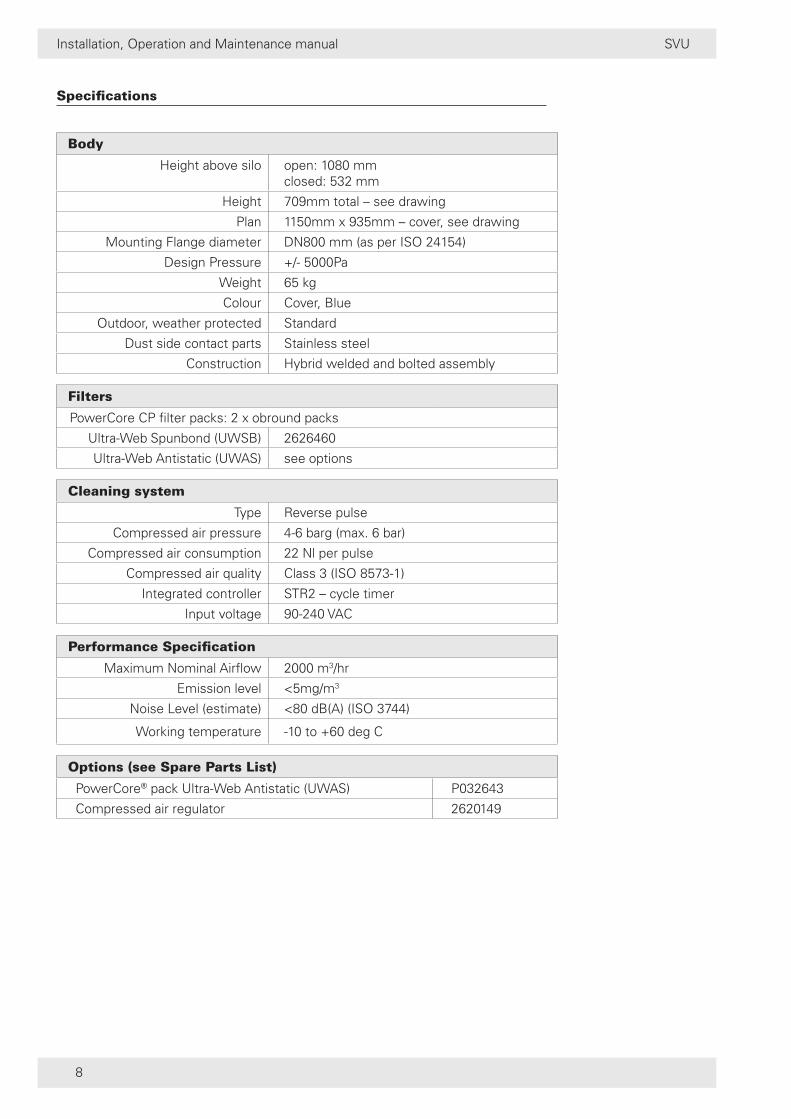
Specifications
Body
Height above silo open: 1080 mmclosed: 532 mm
Height 709mm total – see drawing
Plan 1150mm x 935mm – cover, see drawing
Mounting Flange diameter DN800 mm (as per ISO 24154)
Design Pressure +/- 5000Pa
Weight 65 kg
Colour Cover, Blue
Outdoor, weather protected Standard
Dust side contact parts Stainless steel
Construction Hybrid welded and bolted assembly
Filters
PowerCore CP filter packs: 2 x obround packs
Ultra-Web Spunbond (UWSB) 2626460
Ultra-Web Antistatic (UWAS) see options
Cleaning system
Type Reverse pulse
Compressed air pressure 4-6 barg (max. 6 bar)
Compressed air consumption 22 Nl per pulse
Compressed air quality Class 3 (ISO 8573-1)
Integrated controller STR2 – cycle timer
Input voltage 90-240 VAC
Performance Specification
Maximum Nominal Airflow 2000 m3/hr
Emission level <5mg/m3
Noise Level (estimate) <80 dB(A) (ISO 3744)
Working temperature -10 to +60 deg C
Options (see Spare Parts List)
PowerCore® pack Ultra-Web Antistatic (UWAS) P032643
Compressed air regulator 2620149

Installation, Operation and Maintenance manual
9
SVU
Component overview
1 weather cover 6 compressed air line
2 latch clamp 7 controller
3 mounting flange 8 diaphragm valve
4 PowerCore® filter pack 9 DUNGS pressure switch
5 pack supports 10 t-piece
7
8
9
10
1
2
3
4 5
6
Figure 1: Component overview

Installation, Operation and Maintenance manual
10
SVU
PRIOR TO INSTALLATION
Location
The silo venting unit (SVU) is to be used for venting silos during filling operations.
Consult the technical specification sheet and drawings for the dust collector weight and dimensions.
Required tools and equipment
• crane/fork lift• slings/clevis pins and adequate lifting equipment• standard tools (screwdrivers, wrenches, etc.)• drill• pipe sealant
Delivery and inspection
The dust collector is normally shipped by truck and should be checked for any damage that may have occurred during shipping.
Compare the parts received against the packing list. If there is damage or parts missing, notify the delivery company and your local Donaldson Torit representative.
Packing list consists of:
• 1 SVU (see datasheet)
• 2 Donaldson PowerCore® packs
• 1 lifting lug bar + 1 lifting lug hench (installed on unit)
to be removed after installation
• 1 compressed air regulator (optional)

Installation, Operation and Maintenance manual
11
SVU
INSTALLATION
Unload and transport of the unit
Before unloading, remove all packing and strapping.
The unit is packed in horizontal position, without the filter packs installed. The installation of the filter packs is described in chapter ‘Installation of elements’.
A crane or pallet truck is recommended for the unloading and transport of the SVU.
Do not attempt to lift the unit manually as this may result in serious injuries or damage to the dust collector.
A crane is needed for the installation of the unit. Use appropriate equipment (lifting rope, d-ring shackles, lifting hooks etc.) to lift the entire unit by the lifting parts provided on the unit.
Figure 2: Lifting hooking points
The unit must be lifted by connecting the D-ring shackles / safety hooks to the 3 lifting lugs (= anchor points). Use of any other system does not provide adequate safety.
Before lifting the unit higher than 1 meter, make sure it is properly balanced.

Installation, Operation and Maintenance manual
12
SVU
Figure 3: Lifting unit
Remove the lifting aids after installation and store them in a dry location.
Figure 4: Removal of lifting aids

Installation, Operation and Maintenance manual
13
SVU
Installation of unit
The installation has to be carried out by authorized personnel only. Make sure the safety of the surroundings and operating personnel is guaranteed before commencing the installation.
Make sure all necessary equipment is present and clear installation procedures are laid out.
Ensure that the silo coupling flange is cleaned and that both silo coupling flange and unit coupling flange are free of damage.
The unit must be installed in a horizontal position so that the silo coupling flange and the unit coupling flange are completely aligned. Use a proper sealant or gasket between the flanges to prevent leakage (refer to illustration 6).
If necessary, install a transition piece on the silo to ensure proper fixation of the SVU unit.
The flange of the unit has 24 holes that fit 24 x M8 bolts.
Ø 8
50
EX
T
Ø 10
15°7° 30’
Ø 8
08
Ø 7
73
IN
T S
LEE
VE
All 24 provided holes MUST be used.
Figure 5: Unit coupling flange
The connection between the SVU unit and the silo must be properly sealed (hard seal, liquid seal, ...).

Installation, Operation and Maintenance manual
14
SVU
Apply MS polymer sealant around every hole and along inside of hole pattern, as shown in figure, to ensure correct sealing.
Figure 6: Sealing details
Installation of PowerCore elements
Before performing any maintenance or work on the unit, make sure that: • the electricity is disconnected• the compressed air is disconnected• the manifold is empty
Do not open the unit when windspeed < 19 m/s, during truck unloading or while the unit is performing offline cleaning.
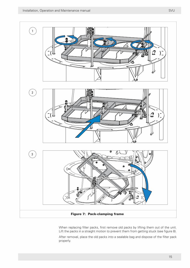
To install/replace elements (see figure 7)1. Unscrew the wing nuts on the pack-clamping frame.2. Slide the frame to the back of the unit.3. Tilt the clamping frame out of the unit and set aside (to the right).
Installation, Operation and Maintenance manual
15
SVU
2
3
1
Figure 7: Pack-clamping frame
When replacing filter packs, first remove old packs by lifting them out of the unit. Lift the packs in a straight motion to prevent them from getting stuck (see figure 8).
After removal, place the old packs into a sealable bag and dispose of the filter pack properly.

Installation, Operation and Maintenance manual
16
SVU
If in doubt regarding the safe disposal of the used filter pack, consult your local regulations.
Figure 8: Removing / replacing filter packs
Before installing new filter packs, clean the surface around the openings where the filter packs will be seated in order to ensure a good seal.
To install new packs, take them out of the carboard box, make sure they do not get in contact with any liquids, and insert them into the unit in a straight motion (see figure 8).
Make sure that the packs are properly sealed against the surface of the unit as to prevent leakages.
After insertion of the new filter packs, reinstall the pack-clamping frame and tighten the wing nuts (reverse of figure 7).
Controller
It is a requirement of the Supply of Machinery (Safety) Regulations 1992 to provide adequate isolation and emergency stop facilities. Due to the varied nature of site installations this cannot be provided by Donladson but instead is the responsibility of the customer.
All electrical work should be carried out by competent personnel.
Before connecting to, or modifying the wiring, make sure that the mains voltage has been removed.
WARNINGS
• It is always mandatory to connect the device to earth through the dedicated terminal on the power supply DIN connector.
• Be careful not to exchange the two DIN connectors (even if the polarisation key on the power supply connector don’t allow dangerous wrong insertions, and the different colour helps to not confuse them). Don’t try to enforce

Installation, Operation and Maintenance manual
17
SVU
the plug-in of the connectors: it is better to renounce and carefully check the connection.
• The DIN 43650 connectors are rated for IP65 protection level, but they should be correctly installed. It is necessary to follow the next steps:
1. Before every manoeuvring on the connectors (insertion, extraction, opening of the cap), it is necessary to disconnect the electric power-supply. The electric charge stored into the internal capacitors will exhaust after 10 sec. It is recommended to wait 10 sec. before performing any servicing.
2. The diameter of the cable used must be compatible with the entry press-cable type PG9 of the DIN connectors used; that means 6÷8 mm diameter.
3. The wires of the cable should be well inserted and fastened in the screw terminals inside the connectors.
4. Always make sure to have connected to earth the intended cable marked with the earth symbol. Internally, this cable is connected to the brass body of the electrovalves which come out on the other side of the instrument.
5. It is always necessary to install the rubber gasket (of a square shape) between the bottom of DIN connectors and the surface of the device’s enclosure.
6. The fastening screw on the connector’s cap should be the original supplied with the connectors or an equivalent one: particularly its head should have a suitable widening, necessary to maintain the declared tightness and to prevent the entry of dust.
POWER
L 1
43
N 2
L Power supplyN Power supply
Ground terminal
1 - 2 terminals: PostP input
3 - 4 terminals: Open terminals
Controller settings
Figure 9: Controller layout
Electrical connections
The supply of the device and its grounding happens through the three FASTON contacts placed on the first black plastic DIN connector. The missing contact serves for polarising the power supply connector avoiding exchange with the one used for the ΔP and PostP input. The power supply should be a 230 VAC signal.
The second grey plastic DIN connector has 4 open slots for the pins and is used to initiate the cleaning.
Terminals 1 and 2 should be wired to the NC contacts of the DUNGS switch (terminal 1 to terminal “P” of DUNGS switch, terminal 2 to terminal “NC” of DUNGS switch).
Make sure the settings on the DUNGS switch are set to 1 mbar.

Installation, Operation and Maintenance manual
18
SVU
In case the controller is not working properly, please double check if the 230 VAC signal is available on top of the silo. There might be losses from power source to controller due to the length of the cables. If power on top of the silo is sufficient, double check the controller settings as explained in chapter ‘Controller Settings’.
Controller settings
To be able to modify the pause and work time, or to enable all or only some of the installed valves, it is necessary to open the transparant plastic window located on the cover of the device. This operation exposes the internal circuit to the potentially explosive atmosphere and then it is mandatory to follow these precautions:• Disconnect the power supply voltage
• Remove the window unscrewing the four fixing screws. Be careful not to lose the screws, the tightening gasket or the plastic window, as they have small dimensions.
• When finished with the control setting, please clean the support surface of gasket and close the transparant window, being careful to properly position the tightening gasket, and finally firmly close the four fixing screws.
Before connecting, or modifying the wiring, make sure that the mains voltage has been removed.

Installation, Operation and Maintenance manual
19
SVU
Rotating Commutator to set the pause time
Position Pause(sec)
F 4*
157,6°
3
Trimmer to set the working time
Working time
min.: 80 msec.
max.: 650 msec.
set time: 100 msec.
1 2 3 4
Dip-switches for various options
Positions
1 OFF PostP enabled
2 ON see note
3 ON see note
4 OFF normal (pause time set by commutator)
note: Dip-switch 2 and 3 are used to set the number of mounted solenoid valves. Solenoid valve 1 is closest to the power supply connector, 2, 3, 4, 5 and 6 follow in order.
Figure 10: Controller settings

Installation, Operation and Maintenance manual
20
SVU
Compressed air connections
The SVU dust filter requires an independent supply of clean, dry compressed air. Details of recommended pressure and air consumption requirements are given in the table below. A design label is attached to each manifold.
In order to ensure the correct air pressure is supplied, a gauge and moisture separator/pressure regulator should be fitted in the line to the filter.
In order to be able to cut off the compressed air supply, it is recommended to install a ball valve or similar device in front of the manifold. This will allow the compressed air being cut off manually when performing maintenance on the unit.
MANIFOLD DESIGN DETAILS
Maximum operating pressure PS: 8 bar
Test pressure PT: 8,8 bar
T: -20 to 70°C
Rating of pressure relief device: 25 dm³/s (factory set at 7,1 bar)not supplied as standard
Product of pressure PS and Volumetric capacity V: 64 bar l
Material used for manifold construction: According to EN13445 with extra Charpy when required
COMPRESSED AIR
Clean air (max. particle size 50 µm)
Free of condensate at working temperature
Max. oil concentration: ISO8573-1 class 3 =< 1 mg/m³
Working compressed air pressure: 4-6 bar (58-87 psig)
Approx. compressed air consumption / pulse *: ±22 Nlitres per pulse
* The indicated value is the consumption per valve
Install safety valve directly in contact with the manifold.
Make sure to use at least 1 inch supply line to avoid large pressure drops in the cleaning system.
ADDITIONAL INFORMATION
pulse duration (fixed) 100 ms
pulse interval (fixed): 4 sec.
compressed air connection 3/4” 19,1 ID / 27 OD (mm) (6)
electrical connection 3G1,5 L+N+PE 230V 6-8 OD (mm)

Installation, Operation and Maintenance manual
21
SVU
START-UP CHECKLIST
Ensure a proper sealant or gasket is used between the unit flange and silo.
Ensure the dust collector is securely bolted to the silo.
Ensure the compressed air connection is connected properly.
Ensure the compressed air pressure is set at 6 bar.
Ensure electrical supply is installed correctly and complies with local electrical legislation.
Double check the controller settings.
Ensure the filter packs are installed correctly and sealed properly.
Ensure the clamping box is tightened up to the mechanical stops.
Ensure the cover is properly closed. Make sure the latch clamp is completely closed.
It is a requirement of the Supply of Machinery (Safety) Regulations 1992 to provide adequate isolation and emergency stop facilities. Due to the varied nature of site installations this cannot be provided by Donladson but instead is the responsibility of the customer.

Installation, Operation and Maintenance manual
22
SVU
OPERATION SCHEDULE
No. Checkpoint Type of controlWeeks
2 4 8
1 Sealant / gasket
Check if still properly sealed (no leakages detected) •
2 Manifold Check if compressed air on top of the silo is still between 4 and 6 barg. •
3 Humidity level Check if there is no moisture or condensation inside the unit. •
4 Filter packs Check if the filter packs are still dry and intact (no traces of moisture or brasing should be visible). •
SERVICE
See section ‘Installation of elements’ in chapter ‘Installation’.
TROUBLESHOOTING GUIDE
Problem Probable cause Remedy
Cleaning system not functioning
No compressed air Check on the compressed air regulator if the range is between 4 to 6 barg. If not, check if ball valve (or similar device) is in the ‘open’ position.
Controller not powered
Check power ON light on timer board’s LED display. If not illuminated, check the supply voltage to the controller (230 VAC 50/60 Hz)
Improper wiring Check wiring between the controller and DUNGS switch (see section ‘Electrical connections’ in chepter ‘Installation’). Check DUNGS switch setting (1 mbar).
Installation, Operation and Maintenance manual
23
SVU
SUPPLEMENTARY INFORMATION
Please read this information carefully before commencing any work. Product reliability, warranty and safe operation may be compromised by not following the guidance given in these documents.
1. The dust collector should be used only when it is in a technically acceptable condition. Regular maintenance, as set out in this manual, is required to minimise technical failure. Third party supplied components should be maintained according to the manufacturer’s instructions.
2. In order to maintain the original collector specification and to ensure the same level of safety, only genuine spare parts should be fitted.
3. You should ensure any persons carrying out work on the supplied equipment follow any relevant recognised standards/codes and are competent to do so. Areas requiring a competent person include:• Maintenance on any component identified as a potential ignition source.• Lifting and erection.• Electrical installation, inspection and maintenance work.• Pneumatic installation, inspection and maintenance work.
4. You should use the dust collector in full accordance with the conditions set out in the Order Acknowledgment or relevant Scope of Delivery. Failure to do so may compromise product reliability, warranty and safety.
5. Other items of equipment, not supplied under the Scope of Delivery from Donaldson Torit, should be installed, operated and maintained according to the documentation supplied with the respective equipment.
6. Where necessary for safety, the dust collector is fitted with fixed guards. Removal of these guards and any subsequent work should only be carried out after adequate precaution is taken to ensure it is safe to do so. All guards should be refitted before re-energising.
7. Ensure the pneumatic system is fully isolated and depressurised before any work is carried out.
8. Care should be taken to ensure that any explosive atmosphere is not present.
9. Any modification carried out on the ‘as supplied’ equipment may reduce reliability and safety, and will nullify warranty; such actions fall outside the responsibility of the original supplier.
10. Compressed air is recommended for collectors that operate using reverse jet cleaning. Alternative gases should be assessed before use to ensure that explosive atmospheres are not introduced during media cleaning.
11. Care should be taken during cleaning and maintenance to avoid creating static discharges that have the potential to ignite a flammable atmosphere.
12. Earthing of the equipment is an integral safety feature. Regular checks should be made (annually) to ensure continuity.