suzhou foif co.,ltd. user manual 1.2e.pdf · instruction manual (ver1.2e) suzhou foif co.,ltd. 2...
TRANSCRIPT
1
OTS650-R300/R500 SERIES RTS650 SERIES TOTAL STATION
Instruction Manual (Ver1.2e)
Suzhou FOIF Co.,Ltd.

2
Foreword
Thanks for you purchasing the FOIF TS650 series total station. In order to use the instrument well, please read this instruction manual carefully and keep it cautiously for consulting in the further.
Product confirmation:
Please fill the model and the serial number of your instrument in corresponding blank. Feedback to local distributor or our sales department.
3
NOTE : ●Please read this instruction manual carefully before use it. ●Avoiding insolates the instrument, and don’t collimate the sun directly for protecting eyes and instrument. ●When using it please insure the connection between tripod and instrument is firm. If raining, you can hood it with rainproof cover. ●Please loose the clamp system when the instrument in the case, and keep the case dry. ●When transporting, keep the instrument in the case and try your best to lighten librations. ●After working in wet or raining condition, please wipe water on surface and keep it in air, when it is dry completely, you can put it in the case. ●Don’t clean the instrument surface with alcohol, aether or other irritant chemical things; and use the equipped paper to clean the optical parts. ●If you do not use the instrument for a long time, you should take the battery pack down and recharge once every month. ●If you do not use the instrument for a long time, take the instrument out of the case and keep it in the dry condition. ●If the temperature changing is sharp (for example: move it out from one hot vehicle), the measured data will be influenced, so it can be used when it adapts the surrounding condition. ●Before use it, you should check the voltage for whether it is enough. ●Do not remove the battery at working time, otherwise some settings or measured data may be lost.

4
Safety Cautions: ●There is a risk of fire, electric shock or physical harm if you attempt to disassemble or repair the instrument yourself. This is only to be carried out by FOIF or an authorized dealer, only! ●Cause eye injury or blindness. Do not look at the sun through a telescope. ●Laser beams can be dangerous, and can cause eye injury if used incorrectly. Never attempt to repair the instrument yourself. ●Cause eye injury or blindness. Do not stare into laser beam. ●High temperature may cause fire. Do not cover the charger while it is charging. ●Risk of fire or electric shock. Do not use damaged power cable, plug and socket. ● Risk of fire or electric shock. Do not use a wet battery or charger. ● May ignite explosively. Never use an instrument near flammable gas, liquid matter, and do not use in a coal mine. ● Battery can cause explosion or injury. Do not dispose in fire or heat. ● Risk of fire or electric shock. Do not use any other type of charger other than the one
specified. ● Risk of fire. Do not use any other power cable other than the one specified. ● The short circuit of a battery can cause a fire. Do not short circuit battery when storing it.

5
CAUTION! ●Do not connect or disconnect equipment with wet hands, you are at risk of electric shocks if you do! ●Risk of injury by overturn the carrying case. Do not stand or sit on the carrying cases. ●Please note that the tips of tripod can be hazardous, be aware of this when setting up or carrying the tripod. ●Risk of injury by falling down the instrument or case. Do not use a carrying case with a damaged which belts, grips or latches. ●Do not allow skin or clothing to come into contact with acid from the batteries, if this does occur then wash off with copious amounts of water and seek medical advice. ●Ensure that you mount the Tribrach correctly, failing to do so may result in injury if the tribrach were to fall over. ●It could be dangerous if the instrument falls over, please check that you fix the instrument to the tripod correctly. ●Risk of injury by falling down a tripod and an instrument. Always check that the screws of tripod are tightened. ● It could cause measurement error when there is leave or other object between instrument and target.
User 1. This product is for professional use only! The user is required to be a qualified surveyor or have a good knowledge of surveying, in order to understand the user manual and safety instructions, before operating, inspecting or adjusting. 2. Wear the required protectors (safety shoes, helmet, etc.) when operating.

6
Exceptions from Responsibility 1) The user of these products is expected to follow all operating instructions and make periodic checks of the product’s performance. 2) The manufacturer, assumes no responsibility for results of a faulty or intentional usage or misuse including any direct, indirect, consequential damage, and loss of profits. 3) The manufacturer assumes no responsibility for consequential damage, and loss of profits by any disaster, (an earthquake, storms, floods etc.). 4) The manufacturer assumes no responsibility for any damage, and loss of profits due to a change of data, loss of data, an interruption of business etc., caused by using the product or an unusable product. 5) The manufacturer assumes no responsibility for any damage, and loss of profits caused by usage except for explained in the user manual. 6) The manufacturer assumes no responsibility for damage caused by wrong transport, or action due to connecting with other products. Safety Standards for OTS650 EDM Laser (OTS650 series) OTS650 series adopt the class of Laser Product according to IEC Standard Publication 60825-1 Amd. 2:2001. According this standard, EDM device is classified as Class 3R Laser Product when reflectless measurement is selected, when the prism and reflective sheet is selected as target, the output is equivalent to the safer class 1. Follow the safety instructions on the labels to ensure safe use.
CAUTION: CLASS 3R LASER RADIATION WHEN OPEN
AVOID DIRECT EYE EXPOSURE.
CAUTION: CLASS 1 LASER RADIATIONS WHEN OPEN
DO NOT STARE INTO THE BEAM

7
Note for Safety
● Never point the laser beam at other’s eyes, it could cause serious injury. ● Never look directly into the laser beam source, it could cause permanent eye damage. ● Never stare at the laser beam, it could cause permanent eye damage. ● Never look at the laser beam through a telescope or other optical devices, it could cause permanent eye damage.
! WARNING
Laser emit

8
Content Applications .......................................................................................1 1. Nomenclature and functions...........................................................2
1.1 Nomenclature .......................................................................2 1.2 Display .................................................................................3 1.3 Operating Key ......................................................................6 1.4 Function key (Soft Key) .......................................................7
2. Battery ............................................................................................9 2.1 Mounting the battery ............................................................9 2.2 Recharge.............................................................................10
3. Preparation for measurement........................................................11 3. 1 Setting up the instrument...................................................11 3.2 Leveling the instrument......................................................11 3.3 Centering ............................................................................12
3.3.1 Centering with optical plummet ..............................12 3.3.2 Centering with laser plummet(Factory Optional)..........................................................................................12
3.4 Focusing .............................................................................13 3.5 Switch on............................................................................13 3.6 Switch off ...........................................................................14 3.7 The function of ★ key menu............................................14 3.8 How to input number and letter..........................................16 3.9 Vertical Angle Tilt Correction............................................17
4. Angle Measurement......................................................................18 4.1 Measuring Horizontal Angle (Right) and Vertical Angle ..18 4.2 Switching Horizontal Angle Right/ Left ............................19 4.3 Set a Horizontal Angle .......................................................20 4.4 Vertical Angle Grade Mode Switch ...................................22 4.5 Zenith distance/ vertical angle mode switch.......................22 4.6 Set Buzzer Sounding for Horizontal Angle 90° .................23

9
5. Distance Measurement................................................................. 24 5.1 Distance Measurement (Slope distance mode) .................. 24 5.2 Distance Measurement (HD/VD mode)............................. 25 5.3 Distance Offset Measurement............................................ 26
5.3.1 Angle offset measurement....................................... 26 5.3.2 Distance Offset Measurement ................................. 28 5.3.3 Plane Offset Measurement ...................................... 30 5.3.4 Column Offset Measurement .................................. 32
5.4 Stake out (S.O)................................................................... 34 5.5 Set distance measurement mode ........................................ 35 5.6 Set distance unit ................................................................. 36 5.7 Setting of the Atmospheric Correction .............................. 37 5.8 Returned signal Checking .................................................. 38 5.9 Setting distance measurement times (Factory setting is “3”)................................................................................................. 39
6. Coordinate Measurement ............................................................. 40 6.1 Setting Coordinate of Occupied point................................ 41 6.2 Setting of instrument height............................................... 42 6.3 Setting of target height....................................................... 43 6.4 Setting coordinate of backsight point................................. 44 6.5 Measuring point coordinate ............................................... 45
7. Data collection ............................................................................. 46 7.1 Data collection menu operation ......................................... 46 7.2 Selecting a file for data collection...................................... 47 7.3 Selecting a coordinate file for data collection.................... 48 7.4 Occupied Point Setting ...................................................... 49 7.5 Backsight Point .................................................................. 51 7.6 Operational Procedure of “Data Collect”........................... 53 7.7 Setting PCODE for measured point ................................... 55
7.7.1 Entering PCODE / ID using PCODE Library......... 55

10
7.7.2 Entering PCODE / ID from the list of PCODE .......56 7.8 Data Collect Offset Measurement mode ............................57
7.8.1 Angle offset measurement .......................................57 7.8.2 Distance Offset Measurement .................................59 7.8.3 Plane Offset Measurement.......................................61 7.8.4 Column Offset Measurement...................................63
7.9 NEZ Auto Calculation........................................................65 7.10 Setting Parameter of Data Collect [CONFIG.].................66
8. Coordiante Layout........................................................................68 8.1 Layout procedures ..............................................................68 8.2 Selecting or creating a coordinate data file ........................68 8.3 Occupied Point Setting .......................................................70 8.4 Setting Backsight Point ......................................................74 8.5 Executing a Layout.............................................................77 8.6 Setting the GRID FACTOR ...............................................80
9. Application Measurement (Programs)..........................................82 9.1 Remote Elevation Measurement (REM) ............................82 9.2 Missing Line Measurement (MLM)...................................85
9.2.2 USE FILE and GRID FACTOR ..............................88 9.2.3 Use coordinate for MLM program ..........................89
9.3 Setting Z Coordinate of Occupied Point.............................90 9.4 Area Measurement .............................................................94
9.4.1 Area Calculation from Coordinate Data File...........94 9.4.2 Area Calculation from measured data .....................95
9.5 Point to Line .......................................................................97 9.6 Setting a new point ...........................................................100
9.6.1 Side short method..................................................100 9.6.2 Resection method ..................................................102
10. Memory Manager Mode .............................................106 10.1 Enter Memory Manager Mode .......................................106

11
10.2 Display Internal Memory Status .................................... 107 10.3 Searching data................................................................ 107
10.3.1 Measured data searching..................................... 107 10.3.2 Coordinate Data Searching ................................. 109 10.3.3 PCODE Library Searching.................................. 110
10.4 File Maintenance............................................................ 111 10.4.1 Rename a file ...................................................... 112 10.4.2 Deleting a File..................................................... 112 10.4.3 Searching Data in a File ...................................... 113
10.5 Coordinate Data Direct Key input ................................. 113 10.6 Delete a Coordinate Data from a File ............................ 115 10.7 Editing PCODE Library................................................. 116 10.8 Data Transfer by serial port(Optional)........................... 117
10.8.1 Sending data........................................................ 117 10.8.2 Loading data........................................................ 118 10.8.3 Setting parameter of data communications ......... 119
10.9 Memory initialize........................................................... 120 10.10 Connect PC via USB port ............................................ 121 10.11 Copy the data files from memory to SD card (Optional)............................................................................................... 123 10.12 Connect TS650 with other device via Bluetooth (Optional)............................................................................................... 124
11. Instrument Settings .................................................................. 125 11.1 Items of instrument settings ........................................... 125 (* factory setting)................................................................... 126 11.2 Enter setting mode ......................................................... 127 11.3 Setting procedures.......................................................... 127
12. Selecting Mode ........................................................................ 128 12.1 Items of selecting mode ................................................. 128 12.2 How to set selecting mode ............................................. 132

12
13. Check and adjustment ..............................................................134 13.1 Checking and adjusting of instrument constant..............134 13.2 Checking/adjusting the plate level..................................136 13.3 Checking/adjusting the circular level Check ..................137 13.4 Checking/adjusting the optical sight...............................138 13.5 Checking/Adjusting the plummet...................................139
13.5.1 Checking/Adjusting the optical plummet Check.139 13.5.2 Checking/Adjusting the laser plummet (Optional accessory) .......................................................................140
13.6 Checking/Adjusting the vertical cross-hair on telescope141 Adjustment .....................................................................................141
13.7 Checking/adjusting horizontal collimation error Check.142 13.8 Checking/adjusting of the vertical index error i. ............142 13.9 Checking the optical axis................................................145
14. Specifications ...........................................................................146 15. Packing list ...............................................................................153 Attachment 1: atmospheric correction formula and chart (for your reference)........................................................................................154 Attachment 2 Correction for refraction and earth curvature ..........157 Attached file 3: communication instruction and data format .........158

1
Applications FOIF TS650 series Total Station applied absolute encoder system to digital angle measurements, it adopt phases measurement system to measure distance. It can measure distance not only with prism but also with reflective sheet, so much as it can work without cooperate objective. It can achieve measurement, calculating, display and storage etc. by means of microcomputer-technology. It can display measuring results of horizontal, vertical angle and distance at the same time. These series Total Station is designed for engineering items, especially for every construction area. It can be used in coordinate measurement or location measurement for construction, remote elevation measurement, plumb line surveying, ductwork surveying and sectional surveying etc. It also can be used in triangulation control survey, cadastral surveying, topographic surveying and house property surveying.

2
1. Nomenclature and functions 1.1 Nomenclature
Leveling screw
Battery
Handle locking screw
Handle
Optical sight
Objective
Plate level
Keyboard
Circular level
Vertical tangent screw
Vertical clamp screw
Horizontal clamp screw Horizontal tangent screw
3
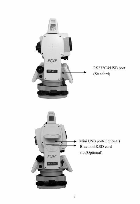
RS232C&USB port (Standard)
Bluetooth&SD card slot(Optional)
Mini USB port(Optional)
4
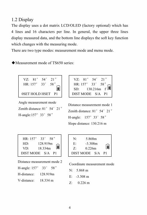
1.2 Display The display uses a dot matrix LCD/OLED (factory optional) which has 4 lines and 16 characters per line. In general, the upper three lines display measured data, and the bottom line displays the soft key function which changes with the measuring mode. There are two type modes: measurement mode and menu mode. ◆Measurement mode of TS650 series:
VZ: 81° 54′ 21″ HR: 157° 33′ 58″ SD: 130.216m f
DIST MODE S/A P1
VZ: 81° 54′ 21″ HR: 157° 33′ 58″
0SET HOLD HSET P1
Angle measurement mode
Zenith distance: 81°54′21″
H-angle:157°33′58″
Distance measurement mode 1
Zenith distance: 81°54′21″
H-angle: 157°33′58″
Slope distance: 130.216 m
N: 5.868m E: -3.308m Z: 0.226m
DIST MODE S/A P1
HR: 157° 33′ 58″ HD: 128.919m VD: 18.334m
DIST MODE S/A P1
Distance measurement mode 2
H-angle: 157° 33′ 58″
H-distance: 128.919m
V-distance: 18.334 m
Coordinate measurement mode
N: 5.868 m
E: -3.308 m
Z: 0.226 m
5
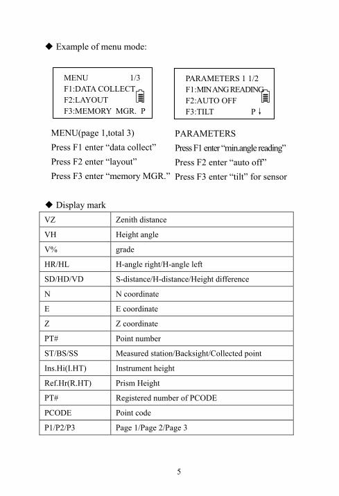
◆ Example of menu mode:
◆ Display mark VZ Zenith distance
VH Height angle
V% grade
HR/HL H-angle right/H-angle left
SD/HD/VD S-distance/H-distance/Height difference
N N coordinate
E E coordinate
Z Z coordinate
PT# Point number
ST/BS/SS Measured station/Backsight/Collected point
Ins.Hi(I.HT) Instrument height
Ref.Hr(R.HT) Prism Height
PT# Registered number of PCODE
PCODE Point code
P1/P2/P3 Page 1/Page 2/Page 3
MENU(page 1,total 3) Press F1 enter “data collect” Press F2 enter “layout” Press F3 enter “memory MGR.”
PARAMETERS Press F1 enter “min.angle reading” Press F2 enter “auto off” Press F3 enter “tilt” for sensor
PARAMETERS 1 1/2 F1:MIN ANG READING F2:AUTO OFF F3:TILT P↓
MENU 1/3 F1:DATA COLLECT F2:LAYOUT F3:MEMORY MGR. P
6
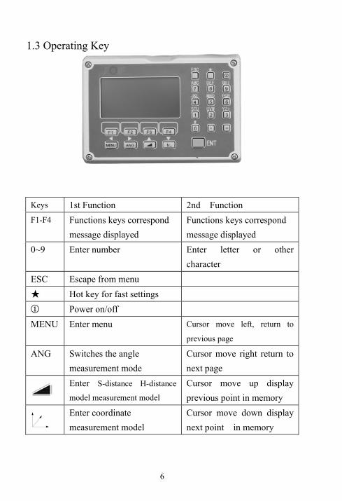
1.3 Operating Key
Keys 1st Function 2nd Function
F1-F4 Functions keys correspond message displayed
Functions keys correspond message displayed
0~9 Enter number Enter letter or other character
ESC Escape from menu
★ Hot key for fast settings
① Power on/off
MENU Enter menu Cursor move left, return to
previous page
ANG Switches the angle measurement mode
Cursor move right return to next page
Enter S-distance H-distance
model measurement model
Cursor move up display previous point in memory
Enter coordinate measurement model
Cursor move down display next point in memory
7
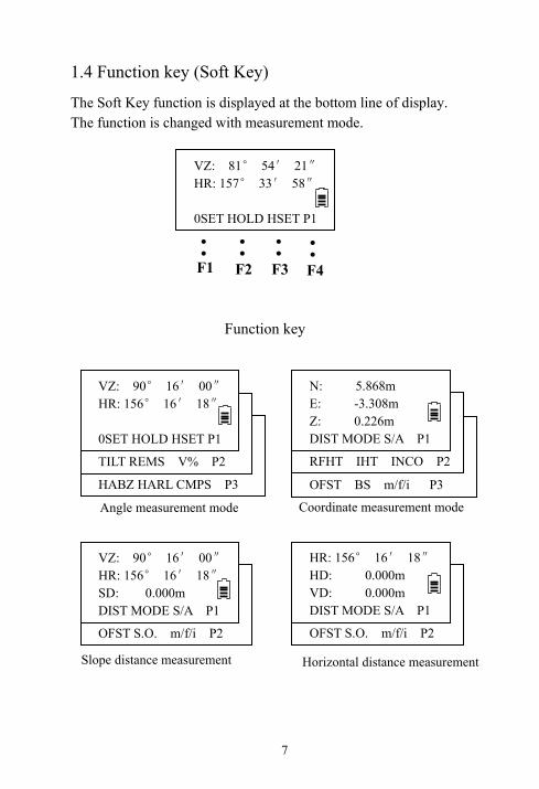
1.4 Function key (Soft Key)
The Soft Key function is displayed at the bottom line of display. The function is changed with measurement mode.
Function key
VZ: 81° 54′ 21″ HR: 157° 33′ 58″ 0SET HOLD HSET P1
●
●
●
●
● ●
●
●
F1 F2 F3 F4
VZ: 81° 54′ 21″ HR: 157° 33′ 58″ HABZ HARL CMPS P3
VZ: 81° 54′ 21″ HR: 157° 33′ 58″ TILT REMS V% P2
VZ: 90° 16′ 00″ HR: 156° 16′ 18″ 0SET HOLD HSET P1
Angle measurement mode
VZ: 81° 54′ 21″ HR: 157° 33′ 58″ OFST BS m/f/i P3
VZ: 81° 54′ 21″ HR: 157° 33′ 58″ RFHT IHT INCO P2
N: 5.868m E: -3.308m Z: 0.226m DIST MODE S/A P1
VZ: 81° 54′ 21″ HR: 157° 33′ 58″ OFST S.O. m/f/i P2
VZ: 90° 16′ 00″ HR: 156° 16′ 18″ SD: 0.000m DIST MODE S/A P1
VZ: 81° 54′ 21″ HR: 157° 33′ 58″ OFST S.O. m/f/i P2
HR: 156° 16′ 18″ HD: 0.000m VD: 0.000m DIST MODE S/A P1
Coordinate measurement mode
Slope distance measurement Horizontal distance measurement

8
Descriptions
Mode Display
mark Soft key Function
0SET F1 Horizontal angle is set to 0
HOLD F2 Hold the horizontal angle P1
HSET F3 Setting horizontal angle by input values
TILT F1 Setting tilt compensator on/off
REMS F2 Enter repeat angle measurement program P2
V% F3 Switch grade/zenith distance VZ
HABZ F1 Buzzer set for every horizontal angle 90°
HARL F2 Switch horizontal angle mode (HR/HL)
Ang
le m
easu
rem
ent
P3
CMPS F3 Set a vertical angle mode(VH/VZ)
DIST F1 Start distance measurement
MODE F2 Select the measurement model as fine or trackP1
S/A F3 EDM setting
OFST F1 Select Offset measurement program
S.O. F2 Select stake out measurement program
S-di
stan
ce m
eas.
P2
m/f/i F3 Change the display of distance unit
DIST F1 Start distance measurement
MODE F2 Select the measurement model as fine or trackP1
S/A F3 EDM setting
RFHT F1 Set prism height
IHT F2 Set instrument height P2
INCO F3 Sets occupied station coordinate
OFST F1 Enter offset measurement program
BS F2 Sets back sight point coordinate
Coo
rdin
ate
mea
s.
P3
m/f/i F3 Change the distance unit

9
Battery clamp
Battery pack
2. Battery 2.1 Mounting the battery (1) Insert the battery by aligning the battery
pack’s tenon with the notch in the instrument,
press the battery clamp and push the top of the
battery pack until you hear a click.
(2)Removing the battery
Press the battery clamp and remove the battery pack by pulling it toward you.
(3)Battery Indicator Battery power display indicates the power condition. You should recharge or replace the battery when you hear the continue buzz. Please turn off in the normal way in order to save the data. Please find the battery operating time on Specifications.
Fig 7 The battery is low.
Need to recharge or
replace the battery.
HR: 82°21′50″ HD: 157°33′58″VD: 0.000m
MODE S/A P
Battery power display
Measurem
ent is possible
DIST
10
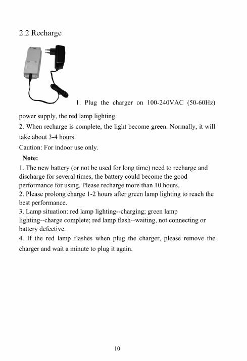
2.2 Recharge
1. Plug the charger on 100-240VAC (50-60Hz)
power supply, the red lamp lighting. 2. When recharge is complete, the light become green. Normally, it will take about 3-4 hours. Caution: For indoor use only. Note:
1. The new battery (or not be used for long time) need to recharge and discharge for several times, the battery could become the good performance for using. Please recharge more than 10 hours. 2. Please prolong charge 1-2 hours after green lamp lighting to reach the best performance. 3. Lamp situation: red lamp lighting--charging; green lamp lighting--charge complete; red lamp flash--waiting, not connecting or battery defective. 4. If the red lamp flashes when plug the charger, please remove the charger and wait a minute to plug it again.

11
3. Preparation for measurement 3. 1 Setting up the instrument (1) Setting up the tripod First, extend the extension legs to suitable lengths and tighten the screws on the midsections (2) Attaching the instrument on the tripod head Place the instrument carefully on the tripod head and slide the instrument by loosening the tripod screw. 3.2 Leveling the instrument (1) Leveling with the circular level by adjusting leveling screws A and B, position the bubble in the center of vial (Fig a). Adjust the leveling screw C, position the bubble in the center of circle (Fig b). (2) Leveling precisely by plate level Loosen horizontal motion clamp, place the plate level in parallel with the line joining leveling screws A and B. Adjust the leveling screws A and B, position the bubble in the center of the plate level (Fig c). Loosen horizontal motion clamp, rotate the plate level through 90°around the vertical axis. Adjust leveling screw C, position the bubble in the center of plate level (Fig d). Repeat above steps until the bubble
remains in the center of plate level
while the instrument is rotated to any
position.
Screw A Screw B
Screw C
Screw A Screw B
Screw C
Fig.a
Fig.b Screw B
Screw C
Screw A
Screw B Screw A
Screw C
Plate level Bubble
Fig. d
Fig. c

12
3.3 Centering 3.3.1 Centering with optical plummet Leveling the instrument by plate level first. Rotate the focusing ring of the optical plummet and adjust the focus to the ground mark point. Then loosen the center screw of the tripod, look through the optical plummet, and move the base plate on the tripod head until the center mark coincides with the ground mark point. At last tighten the center screw. Repeat above steps to leveling the instrument again, until the center of reticle coincides with the mark point when rotating alidade of instrument. 3.3.2 Centering with laser plummet(Factory Optional)
(1) Press ★ key to open fast setting menu, and
press F3 to open plummet laser intensity adjusting
menu, press F1 to increase laser intensity, or press
F2 to decrease laser intensity, at last press F4(ENT)
to confirm.
(2)Turn the focusing knob until the laser spot on
the same horizontal plane with mark point on the
ground.
(3) Loosen the center screw of the tripod, and move the base plate on the tripod
head until the laser spot coincides with the ground mark point. Tighten the center
screw.
(4) Repeat leveling and (3) steps until the instrument keeps leveling and the laser
spot coincides with the mark point when rotating alidade of instrument to any
direction.
(5) After centering, please press [ESC] key.
Cross mark Plummet
center
Laser Point Adjust Level: 4 + ENT

13
Reticle
3.4 Focusing (1) Diopter adjustment
Point telescope to sky or a uniformly light surface (Do not point to the sun). Turn eyepiece until cross hairs are sharp and black. (2) Target image focusing
Look through telescope eyepiece and turn
focusing ring until target is seen. There should
be no apparent movement between cross hairs
and target as observer moves his eye slightly. If there is parallax, please remove
it by adjusting the focusing ring slightly.
3.5 Switch on 1. Confirm the instrument is leveled and centered. 2. Press power key to switch on. 3. It will show the software version and date first, then to show LCD Contrast adjusting screen. It also shows current prism constant value (PSM) and atmospheric correction value (PPM). You could press F1 or F2 to adjust the contrast. Then press F4 to confirm and enter basic measurement mode. Check the battery power indicator, recharge battery when battery level is low or indicates “battery empty”.
Flow chart for switch on
Press power key
FOIF RTS650
V1.3 10-06-22
Contrast Adjust PSM 0.0 PPM -1.2+ - ENT
HR: 82°21'50"
HD: 157°33'58"
VD: 0.000
DIST MODE S/A P1

14
3.6 Switch off (1)Press power key. (2)Press F3 to switch off; Press F4 back to the latest mode. 3.7 The function of ★ key menu ● RTS650 series
(1)Display contrast adjusting ( )
Press ★ key, the display contrast will
be higher if you press (▲)key;
and it will be lower if you press (▼) key.
(2) Illumination on/off( )
Press [F1] key to turn on/off reticle illumination and display backlight.
(3)Tilt On/Off ( )
Press ★ key and displaying the ★menu. Press [F2] to display the tilt medo, the tilt will be on if you press [F1] key and it will be off if you press [F3] key.
(4)Laser plummet intensity adjusting ( )
Press power key
POWER OFF?
YES NO
Press F3 to turn off
Press F4 to escape
Flow chart for switch off
15
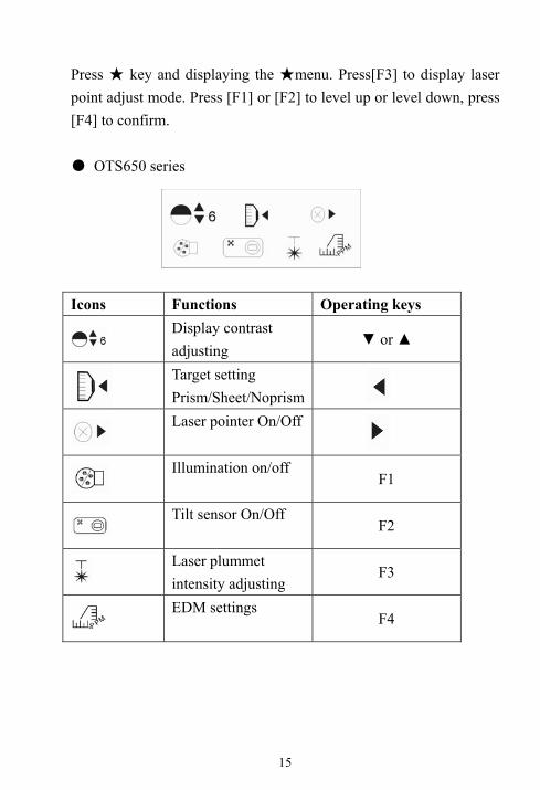
Press ★ key and displaying the ★menu. Press[F3] to display laser point adjust mode. Press [F1] or [F2] to level up or level down, press [F4] to confirm. ● OTS650 series Icons Functions Operating keys
Display contrast adjusting
▼ or ▲
Target setting Prism/Sheet/Noprism
Laser pointer On/Off
Illumination on/off
F1
Tilt sensor On/Off
F2
Laser plummet intensity adjusting
F3
EDM settings
F4
16
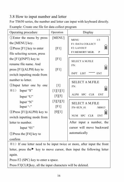
3.8 How to input number and letter For TS650 series, the number and letter can input with keyboard directly. Example: Create one file for data collect program Operating procedure Operation Display ①Enter the menu by press the [MENU] key. ②Press [F1] key to enter file selecting screen, press the [F1](INPT) key to rename file name. And press [F1](ALPH) key to switch inputting mode from number to letter. ③Input letter one by one
1※ ) Input “S”
Input “U” Input “N” Input “-”
④Press [F1](ALPH) key to switch inputting mode from letter to number.
Input “01”
⑤Press the [F4] key to confirm
[MENU]
[F1]
[F1]
[F1]
[1] [1][1][1]
[5][5] [3][3][3]
[F1] [0][1]
After input a number, the cursor will move backward automatically
1※ )If one letter need to be input twice or more, after input the front letter, press the key to move cursor, then input the following letter again. Press F2 (SPC) key to enter a space. Press F3[CLR]key, all the input characters will be deleted.
SELECT A M.FILE FN:
INPT LIST ENT
MENU 1/3 F1: DATA COLLECT F2: LAYOUT F3:MEMORY MGR. P
SELECT A M.FILE FN=SUN_01 /M0015 NUM SPC CLR ENT
SELECT A M.FILE FN:
ALPH SPC CLR ENT

17
3.9 Vertical Angle Tilt Correction When the tilt sensors are activated, automatic correction of vertical angle for mislevelment is displayed. To ensure a precise angle measurement, tilt sensors should be turned on. The display can also be used to precise level the instrument. If the display(X Tilt over) appears the instrument is out of automatic compensation range and must be leveled manually. The vertical angle display is unstable when instrument is on an unstable stage or a windy day. You can turn off the auto tilt correction function in this case. Example: Setting Tilt OFF Operating procedure Operation Display ①Under Angle measurement mode, press[F4] to enter P2. ②Press [F1] key. In case ON is already selected, the display shows tilt correction value. 1※ ) ③Press[F3](OFF) key. ④Press[ESC]key.
[F4]
[F1]
[ F3] [ESC]
1※ )The setting mode performed here will not be memorized after powering OFF. To set TILT correction in the initialized setting ( it is memorized after powering OFF), see Section 6.4.3“Vertical and Horizontal Angle Tilt correction ( Tilt ON/OFF)
TILT [ON] X: -0°1'12″ ON OFF
TILT [OFF] ON OFF
VZ: 82°21′50″ HR: 157°33′58″ TILT REMS V% P2

18
4. Angle Measurement 4.1 Measuring Horizontal Angle (Right) and Vertical Angle Make sure the mode is in Angle measurement Operating procedure Operation Display ①Collimate the 1st target (A). ②Set horizontal angle of target A at 0°00'00, press the [F1](0SET) key and press the [F3] (YES) key. ③Collimate the 2nd target (B).The horizontal angle between B and A and vertical angle of B be displayed.
Collimate
A
[F1] [F3]
Collimate
B
Reference: How to Collimate ①Point the telescope toward the light back ground. Turn the diopter ring and adjust the diopter so that the cross hairs are clearly observed. ②Aim the target at the cross hair of the sighting collimator. Allow a certain space between the sighting collimator and yourself for collimating. ③Focus the target with the focusing knob. ※If parallax is created between the cross hairs and the target when your eyes move vertically or horizontally, focusing is incorrect or diopter adjustment is poor. This affects precision in measurement.
VZ: 89°25′55″ HR: 157°33′58″ 0SET HOLD HSET P1
H-ANG SET0 >SET? --- --- YES NO
VZ: 89°25′55″ HR: 0°00′00″ 0SET HOLD HSET P1
VZ: 124°34′20″ HR: 56°21′01″ 0SET HOLD HSET P1
19
Eliminate the parallax by carefully focusing and using diopter adjustment.
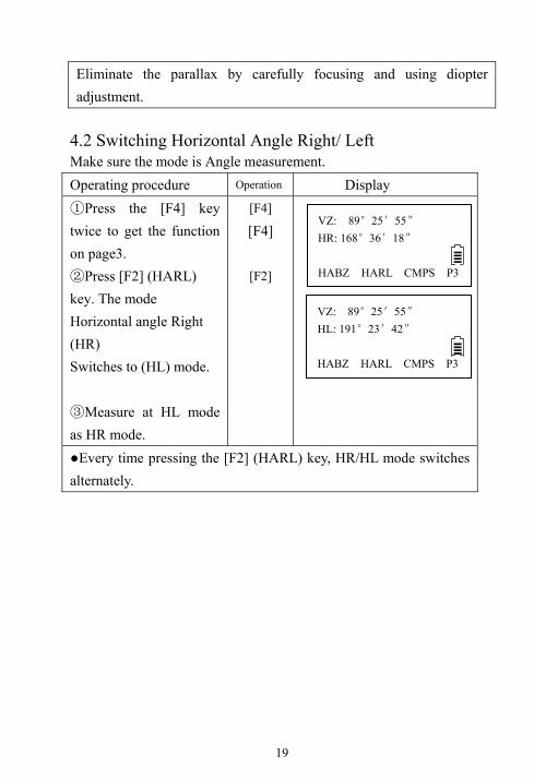
4.2 Switching Horizontal Angle Right/ Left Make sure the mode is Angle measurement. Operating procedure Operation Display ①Press the [F4] key twice to get the function on page3. ②Press [F2] (HARL) key. The mode Horizontal angle Right (HR) Switches to (HL) mode. ③Measure at HL mode as HR mode.
[F4] [F4]
[F2]
●Every time pressing the [F2] (HARL) key, HR/HL mode switches alternately.
VZ: 89°25′55″ HR: 168°36′18″ HABZ HARL CMPS P3
VZ: 89°25′55″ HL: 191°23′42″ HABZ HARL CMPS P3
20
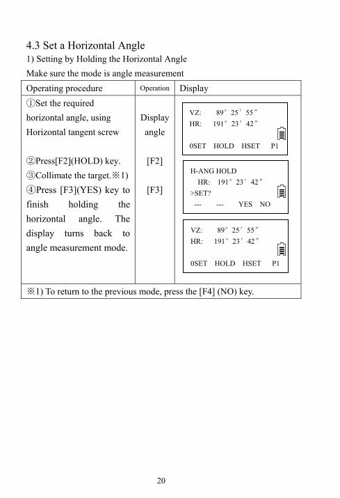
4.3 Set a Horizontal Angle 1) Setting by Holding the Horizontal Angle Make sure the mode is angle measurement Operating procedure Operation Display ①Set the required horizontal angle, using Horizontal tangent screw ②Press[F2](HOLD) key. ③Collimate the target. 1)※
Press ④ [F3](YES) key to finish holding the horizontal angle. The display turns back to angle measurement mode.
Display angle
[F2]
[F3]
1※ ) To return to the previous mode, press the [F4] (NO) key.
VZ: 89°25′55″ HR: 191°23′42″ 0SET HOLD HSET P1
H-ANG HOLD HR: 191°23′42″ >SET? --- --- YES NO
VZ: 89°25′55″ HR: 191°23′42″
0SET HOLD HSET P1
21
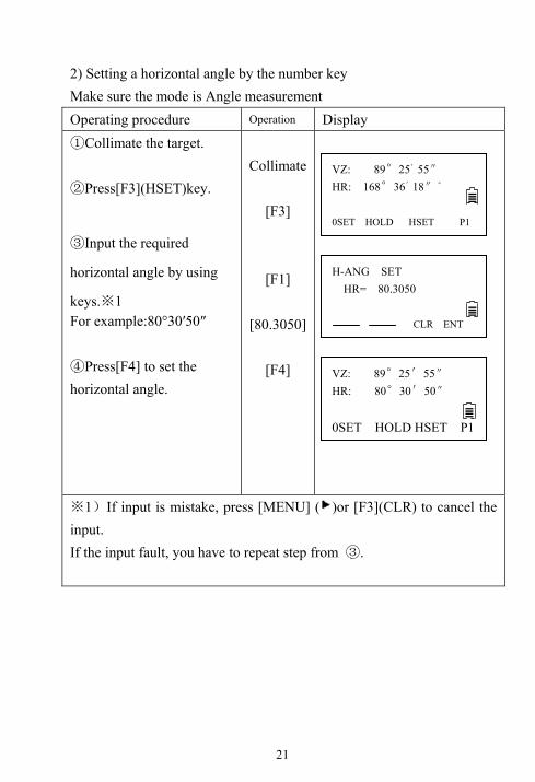
2) Setting a horizontal angle by the number key Make sure the mode is Angle measurement Operating procedure Operation Display ①Collimate the target. ②Press[F3](HSET)key.
③Input the required
horizontal angle by using
keys. 1※ For example:80°30′50″ ④Press[F4] to set the horizontal angle.
Collimate
[F3]
[F1]
[80.3050]
[F4]
1※ )If input is mistake, press [MENU] ( )or [F3](CLR) to cancel the input. If the input fault, you have to repeat step from ③.
VZ: 89°25′55″
HR: 80°30′50″
0SET HOLD HSET P1
H-ANG SET HR= 80.3050
CLR ENT
VZ: 89°25'55″ HR: 168°36'18″"
0SET HOLD HSET P1

22
4.4 Vertical Angle Grade Mode Switch Make sure the mode is Angle measurement
Operating procedure Operation Display ①Press[F4] key to get the
function on page 2.
②Press [F3](V%) key. 1)※
[F4]
[F3]
1)※ Every time pressing the [F3] (V%) key, the display mode switches.
4.5 Zenith distance/ vertical angle mode switch Make sure the mode is Angle measurement Operating procedure Operation Display ①Press [F4] (P1) key to get
the function on page3.
②Press [F3] (CMPS) key.
1)※
[F4]
[F3]
1※ ) Every time press the [F3] key, the display mode switches. ●At VH mode, vertical angle is 0 when telescope is in horizontal direction.
VZ: 67°38′15″ HR: 168° 36′ 19″
0SET HOLD HSET P1
V: 41.13% HL: 168° 36′ 19″
TILT REMS V% P2
TILT REMS V% P2
Vz: 67°38′15″ HR: 168°36′19″
0SET HOLD HSET P1
HABZ HARL CMPS P3
VH: 22° 21′42″ HL: 168° 36′ 19″
HABZ HARL CMPS P3

23
4.6 Set Buzzer Sounding for Horizontal Angle 90° When the horizontal angle falls in the range of ±1°of 0°,90°,180°or 270°, the buzzer sounds. Buzzer stops only when the horizontal angle is adjusted to 0°00′00″, 90°00′00″, 180°00′00″ or 270°00′00″. This setting is not memorized after powering off. Make sure the mode is Angle measurement Operating procedure Operation Display ①Press the [F4] key twice to get the function on page 3.
②Press [F1] key. The previously status is shown on the right up corner. ③Press [F1] (ON) key or [F2] (OFF) key to select the buzzer ON/OFF. ④Press [F4] key to set.
[F4][F4]
[F1]
[F1] or [F2] [F4]
HA Buzzer [OFF] ON OFF --- ENT
VZ: 89°25'55" HR: 168°36'18" HABZ HARL CMPS P3
HABZ HARL CMPS P3
TILT REMS V% P2
Vz: 89° 25′ 55″ HR: 168° 36′ 19″
0SET HOLD HEST P1
HA Buzzer [ON] ON OFF --- ENT

24
5. Distance Measurement 5.1 Distance Measurement (Slope distance mode) Make sure the mode is angle measurement. Operating procedure Operation Display ①Press [ ] key.
②Collimate the center of prism. ③Press[F1]key to start measure distance. 1)※ ○4 The measured distance are shown. 2)※ ~ 5)※
[ ]
[F1]
1※ ) When EDM is working, the“- <”mark appears in the display. 2)※ The measured distance appears with buzzer sounds. 3)※ The displayed measured distance values depend on the different
measurement mode. When the mode is Single measurement, the value is the current measured distance; When the mode is Continuous measurement, the latest display is the average value; When the mode is tracking measurement, the measured distance precision is 0.01m.
4)※ Press [ ] key to change distance measurement mode to (HR,HD,VD) modes.
5)※ If the target is covered, distance can’t be measured. Please make sure there is nothing between the target and instrument telescope.
VZ: 89° 25′ 55″ HR: 168° 36′ 19″
SD: DIST MODE S/A P1
VZ: 89°25'55" HR: 168°36'18" SD * m DIST MODE S/A P1
VZ: 89°25'55" HR: 168°36'18" SD: 88.888 m DIST MODE S/A P1

25
5.2 Distance Measurement (HD/VD mode) Make sure the mode is angle measurement Operating procedure Operation Display ①Press [ ] key twice to into the HD/VD slope distance mode. ②Collimate the center of prism. ③Press [F1] key. 1)※ The measured distances are shown. 2)※ ~ 4)※
[ ] twice
[F1]
1※ ) When EDM is working, the“- <”mark appears in the display. 2)※ The measured distance appears with buzzer sounds. 3)※ The measured distance display values depend on the different
measurement mode. When the mode is Single measurement, the value is the current measured distance; When the mode is Continuous measurement, the latest display is the average value of all; When the mode is tracking measurement, the measured distance precision is 0.01m.
4)※ Press [ ] key to change distance measurement mode to (VZ, HR, SD) modes.
HR: 168°36'18" HD: 0.000m VD: 0.000m DIST MODE S/A P1
HR: 168°36'18" HD: 88.886m VD: 0.002 m DIST MODE S/A P1

26
5.3 Distance Offset Measurement For TS650. Offset measurement has four measuring methods. 1. Angle offset measurement 2. Distance offset measurement 3. Plane offset measurement 4. Column offset measure 5.3.1 Angle offset measurement This program is used to measure the point where is difficult to set prism. Place the prism at the same horizontal distance from the instrument as that of point A0 to measure. When measuring coordinates of ground point A1: Set the instrument height and prism height. When measuring coordinates of point A0, set the instrument height only. (Set the prism height to 0). Make sure the mode is Distance measurement. Operating procedure Operation Display
Press the [F① 4] to page 2.
[F4]
VZ: 89° 25′ 55″ HR: 168° 36′ 19″
SD: DIST MODE S/A P1
OFST S.O m/f/i P2
A0
A1
Prism
Prism height
Instrument hight Occ.point

27
②Press the [F1] (OFST) key. ③Press the [F1](angle offset). ④Collimate the prism. ⑤Press the [F1] (MEAS) key. ⑥Rotate the instrument to collimate the point A0.⑦Each time press [ ] key to display HD, VD, SD in sequence.
⑧Each time press [ ]
key to display N, E, Z in sequence. ○9 Press the [F1] (NEXT) key to measure the next point.
[F1]
[F1]
Collimate
prism [F1]
Collimate
A0
[ ]
[ ]
1) Press F1:[NEXT] back to step ④ 2) Press [ESC] back to distance measurement mode
OFFSET 1/2 F1: ANG. OFFSET F2: DIST. OFFSET F3: PLANE OFFSET
ANGLE OFFSET HR: 0°00′00″ HD m MEAS --- --- ---
ANGLE OFFSET HR: 0°00′00″ HD: 12.345m MEAS--- --- ---
OFFSET MEAS HR: 20°00′00″ VD: 1.345m NEXT--- --- ---
OFFSET MEAS HR: 20°00′00″ N: 501.345m NEXT--- --- ---
28
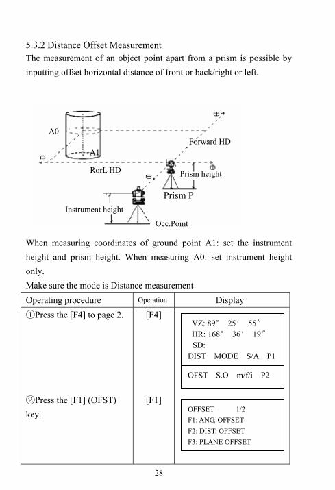
5.3.2 Distance Offset Measurement The measurement of an object point apart from a prism is possible by inputting offset horizontal distance of front or back/right or left. When measuring coordinates of ground point A1: set the instrument height and prism height. When measuring A0: set instrument height only. Make sure the mode is Distance measurement Operating procedure Operation Display ①Press the [F4] to page 2. ②Press the [F1] (OFST) key.
[F4]
[F1]
A0 A0
A1
Instrument height
Prism height
Occ.Point
Prism P
RorL HD
Forward HD
VZ: 89° 25′ 55″ HR: 168° 36′ 19″
SD: DIST MODE S/A P1
OFST S.O m/f/i P2
OFFSET 1/2 F1: ANG. OFFSET F2: DIST. OFFSET F3: PLANE OFFSET

29
③Press the [F2] key (DIST OFFSET). ④Enter Right or Left distance offset value; press [F4] to confirm. ⑤Enter forward distance offset value; press [F4] to confirm. ⑥Rotate instrument to collimate offset point (Prism P). ⑦Press [F1] key, measuring starts. ⑧Measured data of point A is shown. ○9 Each time press [ ] key to display HD, VD, SD in sequence.
○10 press [ ] key to
display N, E, Z of point A ○11 Press the [F1] (NEXT) key to measure the next point.
[F2]
[F4]
[F4]
Collimate
Offset
point [F1]
[ ]
[ ]
[F1]
1) Press F1:[NEXT] back to step ⑥ 2) Press [ESC] back to step ④
DISTANCE OFFSET INPUT RorL HD oHD=1.000
--- --- CLR ENT
DISTANCE OFFSET INPUT FORWARD HD oHD=1.000
--- --- CLR ENT
DISTANCE OFFSET HR: 168° 36′ 19″ SD: 11.789m
MEAS --- --- ---
N: 12.345m E: 23.345m Z: 1.345m MEAS --- --- ---
DISTANCE OFFSET HR: 168° 36′ 19″ HD: 10.000m
NEXT --- --- ---
DISTANCE OFFSET HR: 168° 36′ 19″ SD: 11.789m
MEAS --- --- ---
30
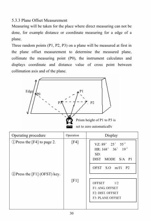
5.3.3 Plane Offset Measurement Measuring will be taken for the place where direct measuring can not be done, for example distance or coordinate measuring for a edge of a plane. Three random points (P1, P2, P3) on a plane will be measured at first in the plane offset measurement to determine the measured plane, collimate the measuring point (P0), the instrument calculates and displays coordinate and distance value of cross point between collimation axis and of the plane. Operating procedure Operation Display ①Press the [F4] to page 2. ②Press the [F1] (OFST) key.
[F4]
[F1]
P0 P1
P2 P3
Prism height of P1 to P3 is
set to zero automatically
Edge
VZ: 89° 25′ 55″ HR: 168° 36′ 19″
SD: DIST MODE S/A P1
OFST S.O m/f/i P2
OFFSET 1/2 F1: ANG. OFFSET F2: DIST. OFFSET F3: PLANE OFFSET
31
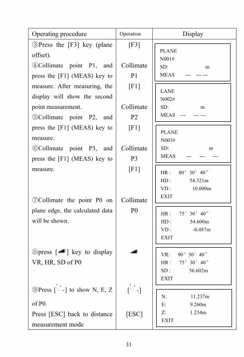
Operating procedure Operation Display ③Press the [F3] key (plane offset). ④Collimate point P1, and
press the [F1] (MEAS) key to
measure. After measuring, the
display will show the second
point measurement. ⑤Collimate point P2, and
press the [F1] (MEAS) key to
measure. ⑥Collimate point P3, and
press the [F1] (MEAS) key to
measure.
⑦Collimate the point P0 on
plane edge, the calculated data
will be shown.
⑧press [ ] key to display VR, HR, SD of P0
⑨Press [ ] to show N, E, Z
of P0.
Press [ESC] back to distance measurement mode
[F3]
Collimate P1
[F1]
Collimate P2
[F1]
Collimate P3
[F1]
Collimate P0
[ ]
[ESC]
PLANE N001# SD: m MEAS --- --- ---
LANE N002# SD: m MEAS --- --- ---
PLANE N003# SD: m MEAS --- --- ---
HR : 80°30′40″ HD : 54.321m VD : 10.000m EXIT
HR : 75°30′40″ HD : 54.600m VD : -0.487m EXIT
VR: 90°30′40″ HR : 75°30′40″ SD : 56.602m EXIT
N: 11.237m E: 9.260m Z: 1.234m EXIT

32
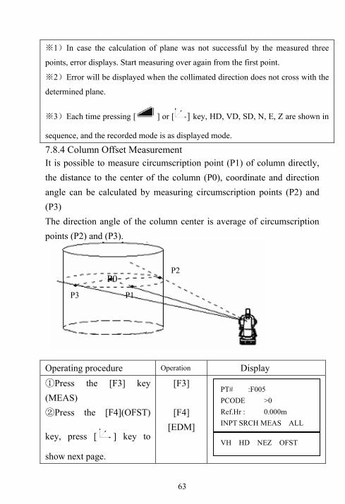
5.3.4 Column Offset Measurement It is possible to measure circumscription point (P1) of column directly, the distance to the center of the column (P0), coordinate and direction angle can be calculated by measuring circumscription points (P2) and (P3) The direction angle of the column center is average of circumscription points (P2) and (P3). Make sure the mode is Distance measurement Operating procedure Operation Display ① Press the [F4] to page
2. ② Press the [F1] (OFST)
key. ③ Press ▼key to display
next page
[F4]
[F1] ▼
P1
P2
P3
P0
VZ: 89° 25′ 55″ HR: 168° 36′ 19″
SD: DIST MODE S/A P1
OFST S.O m/f/i P2
OFFSET 2/2
F1: COLUMN OFFSET
OFFSET 1/2 F1: ANG. OFFSET F2: DIST. OFFSET F3: PLANE OFFSET

33
Press the [F1] (column offset) key. ④Collimate the center of column P1, and press the [F1] (MEAS) key to measure N times. ⑤Collimate the left side of the column (P2) and press the [F4] (SET) key. ⑥Collimate the right side of the column (P3) and press the [F4] (SET) key. ⑦The distance between the instrument and center of the column (P0) will be calculated and shown.
Each time p⑧ ress [ ] key to display HD, VD, SD in sequence.
⑨Press [ ] to show N, E,
Z of column center.
Collimate P1
[F1]
Collimate P2
[F4]
Collimate P3
[F4]
[ ]
[F3]
COLUMN OFFSET Center HD: m MEAS --- --- ---
COLUMN OFFSET Center HD* 1.234m < Measuring>
COLUMN OFFSET Left HR: 12°34′56″ --- --- --- SET
COLUMN OFFSET Right HR: 12°34′56″ --- --- --- SET
COLUMN OFFSET HR: 12°34′56″ HD: 1.234m NEXT --- --- ---
COLUMN OFFSET HR: 12°34′56″ VD: 0.000m NEXT --- --- ---

34
5.4 Stake out (S.O) The difference between the measured distance and the input stake out distance is displayed. Displayed value=Measured distances-Stake out distance In stake out operation, you can select either horizontal distance (HD), relative elevation(VD)or slope distance (SD). Make sure the mode is Distance measurement Operating procedure Operation Display ①Press [F4] (P1) key from distance measuring mode to get the function on page 2. ②Press [F2] (S.O) key. ③Press[F1](HD) key. 1)※ ④Enter the distance for stake out and press [F4] key. Collimate the prism. ⑤Press [F4] key to return HD mode page 1, press [F1] starts measuring. +value means move prism toward the instrument. -value means move prism backward the instrument.
[F4]
[F2]
[F1] [F4]
[F4] [F1]
SET OUT HD: 0.000m HD VD SD ---
SET OUT HD: 10.000m ---- ---- CLR ENT
HR: 168°36'18" dHD: -12.410m VD: 0.000m OFST S.O. m/f/i P2
HR: 168°36'18" dHD: -12.410m VD: 0.000m DIST REC --- P1
VZ: 89° 25′ 55″ HR: 168° 36′ 19″
SD: DIST MODE S/A P1
OFST S.O m/f/i P2
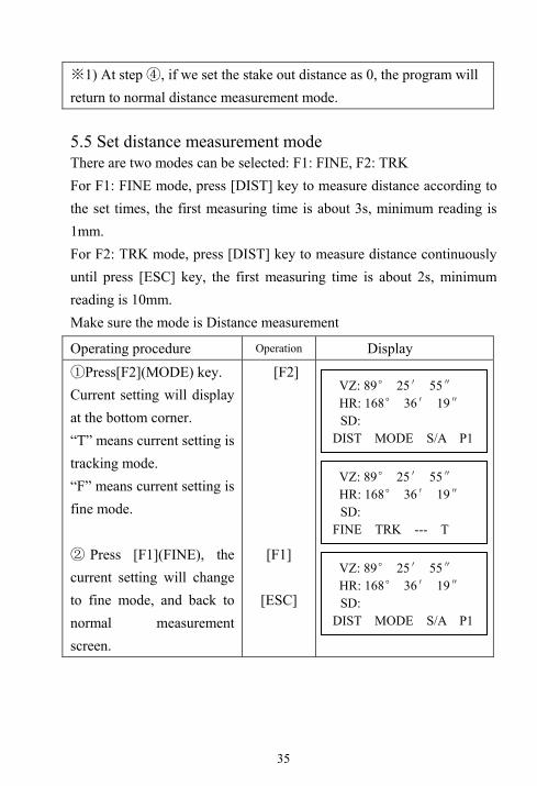
35
1) At※ step ④, if we set the stake out distance as 0, the program will return to normal distance measurement mode. 5.5 Set distance measurement mode There are two modes can be selected: F1: FINE, F2: TRK For F1: FINE mode, press [DIST] key to measure distance according to the set times, the first measuring time is about 3s, minimum reading is 1mm. For F2: TRK mode, press [DIST] key to measure distance continuously until press [ESC] key, the first measuring time is about 2s, minimum reading is 10mm. Make sure the mode is Distance measurement
Operating procedure Operation Display ①Press[F2](MODE) key. Current setting will display at the bottom corner. “T” means current setting is tracking mode. “F” means current setting is fine mode. ② Press [F1](FINE), the current setting will change to fine mode, and back to normal measurement screen.
[F2]
[F1]
[ESC]
VZ: 89° 25′ 55″ HR: 168° 36′ 19″
SD: DIST MODE S/A P1
VZ: 89° 25′ 55″ HR: 168° 36′ 19″
SD: FINE TRK --- T
VZ: 89° 25′ 55″ HR: 168° 36′ 19″
SD: DIST MODE S/A P1

36
5.6 Set distance unit Make sure the mode is Distance measurement
Operating procedure Operation Display ① Press[F4](P1) key from distance measuring mode to get the function on page 2. ② Every time press [F3](m/f/i), the current unit will change among m, ft, inch in sequence.
[F4]
[F3]
VZ: 89° 25′ 55″ HR: 168° 36′ 19″
SD: m DIST MODE S/A P1
OFST S.O m/f/i P2
VZ: 89° 25′ 55″ HR: 168° 36′ 19″
SD: f OSET S.O. m/f/I P2

37
5.7 Setting of the Atmospheric Correction These series Total Station setting the atmospheric correction value by input directly the temperature and pressure value. Operating procedure Operation Display ① Press[★]key.
② Press [F4]( )
key.
③ Press [F3] key.
④Input the prism constant correction value. ⑤Press[F4]key to save the setting.
[★] [F4]
[F3]
[F4]
The atmospheric correction is little effect on distance measurement. But if the input Temp. value and pressure value is big different from the measuring value, the distance different should be more than 0.001m. Input range: -40.0℃< Temperature< +60.0℃
-40.0℉< Temperature< +140.0℉ Input range: +500.0hpa<Pressure< +1500.0hpa
EDM SET F1: PSM-30.0 PPM -1.9 Signal: [ ] PSM PPM T-P TIMS
PPM:000 TEMP = 18.0_ °C PRES : 1020.0 hPa --- --- CLR ENT
PPM:000 TEMP = 25_ °C PRES : 1020.0 hPa --- --- CLR ENT

38
+500.0mbar<Pressure< +1500.0mbar +375.0mmHg<Pressure< +1125.0mmHg +14.8inhg<Pressure< +44.3inhg +7.3psi<Pressure< +21.8hpa 5.8 Returned signal Checking Check to make sure that sufficient reflected light is returned by the reflective prism sighted by the telescope. Operating procedure Operation Display ① Press[★]key.
② Press [F4]
key.
③ The intensity of current returned signal is shown on the third line.. ④ Press[ESC]key to return the previous mode.
[★] [F4]
[ESC]
EDM SET F1: PSM-30.0 PPM -1.9 Signal: [ ] PSM PPM T-P TIMS
39
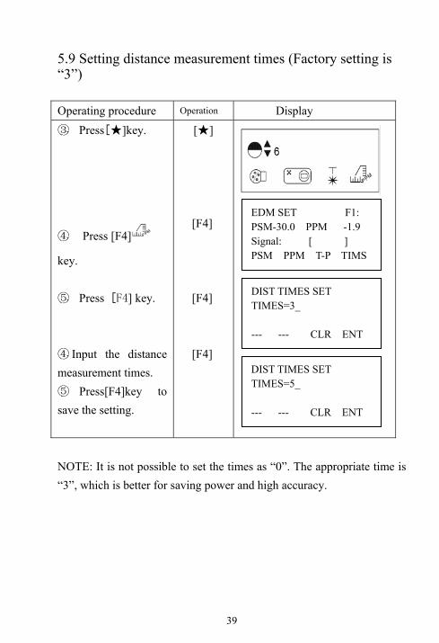
5.9 Setting distance measurement times (Factory setting is “3”) Operating procedure Operation Display ③ Press[★]key.
④ Press [F4]
key.
⑤ Press [F4] key.
④ Input the distance measurement times. ⑤ Press[F4]key to save the setting.
[★] [F4]
[F4]
[F4]
NOTE: It is not possible to set the times as “0”. The appropriate time is “3”, which is better for saving power and high accuracy.
EDM SET F1: PSM-30.0 PPM -1.9 Signal: [ ] PSM PPM T-P TIMS
DIST TIMES SET TIMES=3_ --- --- CLR ENT
DIST TIMES SET TIMES=5_ --- --- CLR ENT
40
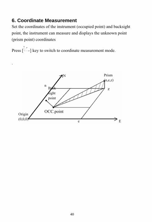
6. Coordinate Measurement Set the coordinates of the instrument (occupied point) and backsight point, the instrument can measure and displays the unknown point (prism point) coordinates
Press [ ] key to switch to coordinate measurement mode.
. E
Origin
(0,0,0) Prism (n,e,z)
z
e
OCC.point
n
N
Back sight point
E
Origin (0,0,0)

41
6.1 Setting Coordinate of Occupied point
1) Coordinate data input by keyboard directly Operating procedure Operation Display
①Press [ ] key.
②Press [F4] key to display the function page2. ③Press [F3] (INCO) key. ※1) ④Enter the coordinate. ※2) ⑤After NEZ coordinate is entered, press [F4] to confirm, the instrument returns coordinate measurement menu on page 2.
[ ]
[F4]
[F3]
Enter NEZ data
[F4]
※1)“=”means the current entering item, the item can be entered right now. After enter and press [F4] key, the“=” moves to the next line. If this item need not to enter, press [F4] key to move “=” directly. ※2)Input range: -99999999.9990m< N,E,Z< +99999999.9990m Input range: -99999999.9990ft< N,E,Z< +99999999.9990ft Input range: -99999999.11.7ft+in< N,E,Z< +99999999.11.7ft+in
RFHT IHT INCO P2
N : 0.000m E : 0.000m Z : 0.000m DIST MODE S/A P1
N = 0.000_ m E : 0.000m
Z : 0.000m
--- --- CLR ENT
N : 123.456m E : -987.015m
Z : 0.803 m
--- --- CLR ENT

42
6.2 Setting of instrument height After power off, the instrument height can be saved. Operating procedure Operation Display
①Press [ ] key.
②Press [F4] key to display the function page2. ③Press [F2] (IHT) key. ④Enter the instrument height, press F4 to confirm, the instrument returns coordinate measurement menu on page 2. ※1)
[ ]
[F4]
[F2]
Enter Inst.H
[F4]
※1)Input range: -999.9990m< Inst.H< +999.9990m Input range: -999.9990ft< Inst.H< +999.999f0t Input range: -999.11.7 ft+in< Inst.H< +999.11.7 ft+in
RFHT IHT INCO P2
N : 123.456m E : -987.015m
Z : 0.803 m
DIST MODE S/A P1
INSTRUMETN HEIGHT INPUT Ins.Hi=1.174_ m --- --- CLR ENT
N : 123.456m E : -987.015m
Z : 0.803 m
RFHT IHT INCO P2

43
6.3 Setting of target height After power off, the target height can be saved. Operating procedure Operation Display
①Press [ ]key .
②Press[F4]key to display the function page2. ③Press[F1](RFHT)key. ④Enter the target height, press F4 to confirm, the instrument returns coordinate measurement menu on page 2.. ※1)
[ ]
[F4]
[F1]
Enter Targ.H
[F4]
※1)Input range: -999.9990m< Ref.H< +999.9990m Input range: -999.9990ft< Ref.H< +999.9990ft Input range: -999.11.7 ft+in< Inst.H< +999.11.7 ft+in
RFHT IHT INCO P2
N : 123.456m E : -987.015m
Z : 0.803 m
DIST MODE S/A P1
REF HT INPUT Ref.Hr=2.500_ m --- --- CLR ENT
N : 123.456m E : -987.015m
Z : 0.803 m
RFHT IHT INCO P2

44
6.4 Setting coordinate of backsight point Direct key input of coordinate data Operating procedure Operation Display ①Displaying the coordinate measurement mode on page3. ②Press [F2] key to get the function of setting backsight point. ③Enter the coordinate. ④After NEZ coordinate is entered; press [F4] to confirm. ⑤Collimate backsight point prism center, press [F3] (YES) key. The azimuth angle is set, and instrument returns coordinate measurement menu on page 3.
[F2]
Input N,E,Z [F4]
AIM [F3]
OFST BS m/f/i P3
RFHT IHT INCO P2
N : 123.456m E : -987.015m
Z : 0.803 m
DIST MODE S/A P1
N= 0.000_ m E : 0.000m Z: 0.000m --- --- CLR ENT
N= 0.000m E : 0.000m Z: 0.000m
--- --- CLR ENT
BACKSIGHT HR: 12°34′56″ >Sight? YES NO
N : 123.456m E : -987.015m
Z : 0.803 m
OFST BS m/f/i P3

45
6.5 Measuring point coordinate After setting the coordinate of instrument and backsight, instrument height and target height, collimate the point to measure its coordinate. Operating procedure Operation Display ①In coordinate measurement mode function page1. ②Collimate prism, press [F1] key, the instrument begins to measure distance and then give the final result.
Collima
te [F1]
N : 123.456m E : 987.654m Z 1.000m DIST MODE S/A P1
N:*[3] -< m E : 1020.821m Z -2.345m DIST MODE S/A P1
N : 135.400m E : 1020.821m Z : -2.345m DIST REC --- P1

46
7. Data collection These series total station is able to store the measured data into the internal memory. The internal memory is shared by the measured data files and the coordinate data files. 7.1 Data collection menu operation
Set file
MENU 1/3 F1: DATA COLLECT F2: LAYOUT F3: MEMORY P↓
F1
SELECT A MFILE FN: INPT LIST --- ENT
COLLECT 1/2 F1: OCC. PT# INPT F2: BACKSIGHT F3: FS/SS
Occ. point
Setting occupied point.
Refer to 8.4
Backsight
Setting backsight point.
Refer to 8.5
FS/SS Executing data
collection. Refer to 8.6 Data collection menu 1/2
▼ ▲
COLLECT 2/2 F1: SELECT A FILE F2: PCODE INPUT F3: CONFIG
Select a file
PCODE input
Selecting a coordinate
file. Refer to 8.3
Editing PCODE library.
Refer to 8.8

47
7.2 Selecting a file for data collection Select a file before beginning data collection. The measured data could be stored into the selected file. Operating procedure Operation Display ①Press [MENU] key enter the menu display. ②Press [F1] key enter data collection. ③Press [F2] key to display the file list.
1※ ) ④Scroll file list by pressing [▲]or [ ▼ ] key and select one file to use. 2※ ) ⑤Press [F4] key. The file will be set.
[MENU]
[F1]
[F2]
[▲] [ ▼ ]
[F4]
※1)If you want to input file name directly, press[F1] key and enter a file name.
2※ )When a file has been selected already, “*”mark is indicated on left of current file name. ● It is possible to select a file from DATA COLLECT 2/2, menu in the same way.
1 /C0003 >*1SV /C0000 S /C0000 TOP LAST SRCH ENT
MENU 1/3 F1:DATA COLLECT F2:LAYOUT F3: MEMORY MGR P↓
SELECT A MFILE FN: INPT LIST --- ENT
> *1 /C0003 1SV /C0000 TOP LAST SRCH ENT
COLLECT 1/2 F1: OCC. PT# INPT F2: BACKSIGHT F3:FS/SS

48
7.3 Selecting a coordinate file for data collection When coordinate data in a coordinate date file are used for occupied point or backsight point, select a coordinate file beforehand. Operating procedure Operation Display ①Enter the page 2 of data collection menu. ② Press [F1 key. ③Press [F2] key. ④ Press[F2] key to display the list of file. ⑤Scroll file list by pressing [▲]or [▼] key and select a file to use.
⑥Press [F4]key. The file will be set.
[F1]
[F2]
[F2]
[ ▼ ]
[F4]
COLLECT 2/2 F1 : SELECT A FILE F2 :PCODE INPUT F3 :CONFIG P↓
SELECT A FILE FN: INPT LIST --- ENT
> @FOIF_01/0012 FOIF_02/0102 FOIF_03/0008 TOP LAST SRCH ENT
FOIF_01/0012 > @FOIF_02/0102 FOIF_03/0008 TOP LAST SRCH ENT
COLLECT 2/2 F1 :SELECT A FILE F2 :PCODE INPUT F3 :CONFIG
SELECT A FILE F1 : MEAS.FILE F2: COORD.FILE

49
7.4 Occupied Point Setting 1) Setting the coordinate data from the internal memory. Operating procedure Operation Display ①Make sure the displaying is Data Collect menu. ②Press [F1] (OCC. PT#
INPUT) key, displays PT# input menu. ③Press [F4] key. ④Press[F2] key to display the list of PT#. 1※ ) ⑤Scroll PT# list by pressing [▲] or [▼] key and select PT#. Press [F4] key.
2※ ) 3※ ) ⑥Press [F3] to select YES. ⑦Enter Ins. Hi, PCODE, Press [F3] key. 4※ )
[F1]
[F4]
[F2]
[▲]or [▼] [F4]
[F3]
1※ )If you want to input PT# directly, press [F1]key and enter PT#.
2※ )The coordinate data can be viewed by press [F1](VIEW)key.
3※ )The coordinate data can be searched by press [F2](SRCH) key.
4※ )If the input number is 1-50, it should be ID of PCODE in library.
PT# > PCODE : Ins.Hi : 1.000 m INPT SRCH REC STN
COLLECT 1/2 F1 : OCC. PT# INPUT F2 :BACKSIGHT F3 :FS/SS P↓
OCC. PT PT#: INPT LIST NEZ ENT
[FOIF ] > F001 F002 VIEW SRCH --- ENT
N 5.620m E 4.210m Z 1.250m >OK? YES NO
PT# >F001 PCODE : Ins.Hi : 1.000 m INPT SRCH REC STN

50
2) Input the instrument point coordinates by hand Operating procedure Operation Display ①Make sure the displaying is Data Collect menu. ②Press[F1]( OCC. PT#
INPUT) key , displays PT# input menu. ③Press [F4] key. ④ Press [F3] (NEZ) to enter coordinate input menu. ⑤Press[F1]key and enter coordinate values. ※ 1) ⑥ Press [F3] (YES) to record the input coordinate to memory. ⑦After enter the PT# and then press [F4] to confirm
[F1]
[F4]
[F3] [F1] Input coord [F4]
[F3]
[F4]
COLLECT 1/2 F1: OCC. PT# INPT F2: BACKSIGHT F3: FS/SS
PT# > PCODE: Ins.Hi : 1.000 m INPT SRCH REC STN
OCC. PT PT#: INPT LIST NEZ ENT
N: 123.456 m E: 987.654 m Z= -1.608_ m --- --- CLR ENT
N: 123.456 m E: 987.650 m Z: -1.608 m >REC ? [YES] [NO]
INPUT COORD PT# : 5 INPT LIST --- ENT
PT# >5 PCODE : Ins.Hi : 1.000 m INPT SRCH REC STN
51
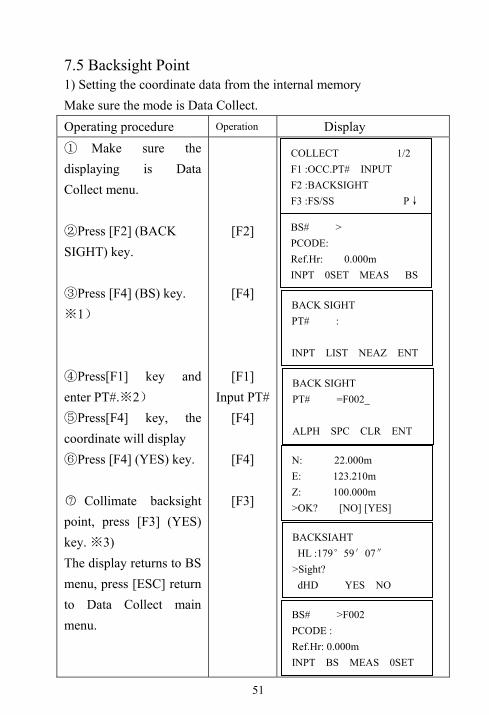
7.5 Backsight Point 1) Setting the coordinate data from the internal memory Make sure the mode is Data Collect. Operating procedure Operation Display ① Make sure the displaying is Data Collect menu. ②Press [F2] (BACK SIGHT) key. ③Press [F4] (BS) key.
1※ ) ④Press[F1] key and enter PT#. 2※ ) ⑤Press[F4] key, the coordinate will display ⑥Press [F4] (YES) key. ○7 Collimate backsight point, press [F3] (YES) key. ※3) The display returns to BS menu, press [ESC] return to Data Collect main menu.
[F2]
[F4]
[F1] Input PT#
[F4]
[F4]
[F3]
BS# > PCODE: Ref.Hr: 0.000m INPT 0SET MEAS BS
BACK SIGHT PT# : INPT LIST NEAZ ENT
BACK SIGHT PT# =F002_ ALPH SPC CLR ENT
N: 22.000m E: 123.210m Z: 100.000m >OK? [NO] [YES]
BACKSIAHT HL :179°59′07″ >Sight?
dHD YES NO
BS# >F002 PCODE : Ref.Hr: 0.000m INPT BS MEAS 0SET
COLLECT 1/2 F1 :OCC.PT# INPUT F2 :BACKSIGHT F3 :FS/SS P↓

52
1※ )The coordinate data can be searched by press [F2](LIST)key. 2)※ Press [F3] key, bacsight setting mode will be switched among
NEAZ/AZ/PT#. ※3) Press [F1](dHD) to measure the horizontal difference between calculated Backsight and true backsight. 2) Setting the direction angle Make sure the mode is Data Collect. Operating procedure Operation Display ① Make sure the displaying is Data Collect menu. ② Press [F2](BACK SIGHT) key. ③Press[F4](BS) key. ※1) ④Press [F3] twice to enter AZ inputting menu.
⑤ Press[F1] key, input the direction angle. 186°56′00″ Press [F4] key.
[F2]
[F3]
[F3]
[F1] [186.5600]
[F4]
BS# > PCODE: Ref.Hr: 0.000m INPT 0SET MEAS BS
BACK SIGHT PT# : INPT LIST NEAZ ENT
BACK SIGHT HR: INPT ---- PT# ENT
BACK SIGHT HR=186.5600_ --- --- CLR ENT
COLLECT 1/2 F1 :OCC.PT# INPUT F2 :BACKSIGHT F3 :FS/SS P↓

53
⑥ Collimate backsight point, press [F3]key. The display returns to BS menu.
Collimate
backsight
point [F3]
7.6 Operational Procedure of “Data Collect” Make sure the mode is Data Collect. Operating procedure Operation Display ①Press [F3] (FS/SS) key. ②Press [F1] key and input PT#, PCODE, Ref.Hr. Press [F3](MEAS)key. 1※ ) ③There are four modes can be selected, press [F2](HD) key, HD/VD data will be measured. 2※ ) 3※ ) ④Press [F3](YES) to record the measured data to memory.※4) ④The display changes to previous menu, and it is ready to measuring next point. PT# is automatically incremented.
[F3]
[F3]
[F2]
[F3]
[F4]
PT# > PCODE : 0 Ref.Hr : 0.000m INPT SRCH MEAS ALL
PT# :F021 PCODE : FOIF Ref.Hr : 1.000m VH HD NEZ OFST
HR : 0°00′00″ HD: m VD -< <Meauring>
HA : 58°14′22″ HD: 56.461 m VD: 5.625 m >OK [YES] [NO]
BACKSIAHT HL :186°56′00″ >Sight? YES NO
PT# :F022 ID :FOIF Ref.Hr : 1.000m INPT SRCH MEAS ALL
54
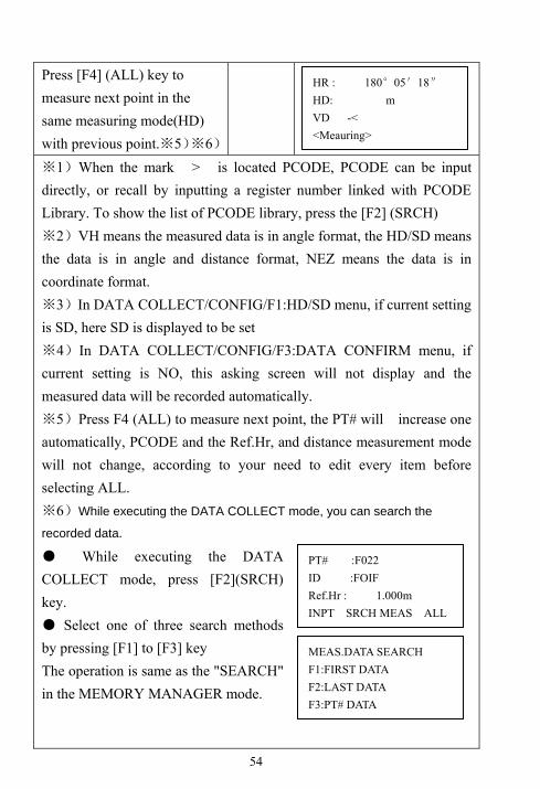
Press [F4] (ALL) key to measure next point in the same measuring mode(HD) with previous point.※5)※6)
1※ )When the mark > is located PCODE, PCODE can be input directly, or recall by inputting a register number linked with PCODE Library. To show the list of PCODE library, press the [F2] (SRCH)
2※ )VH means the measured data is in angle format, the HD/SD means the data is in angle and distance format, NEZ means the data is in coordinate format. ※3)In DATA COLLECT/CONFIG/F1:HD/SD menu, if current setting is SD, here SD is displayed to be set ※4)In DATA COLLECT/CONFIG/F3:DATA CONFIRM menu, if current setting is NO, this asking screen will not display and the measured data will be recorded automatically. ※5)Press F4 (ALL) to measure next point, the PT# will increase one automatically, PCODE and the Ref.Hr, and distance measurement mode will not change, according to your need to edit every item before selecting ALL. ※6)While executing the DATA COLLECT mode, you can search the
recorded data.
● While executing the DATA COLLECT mode, press [F2](SRCH) key. ● Select one of three search methods by pressing [F1] to [F3] key The operation is same as the "SEARCH" in the MEMORY MANAGER mode.
HR : 180°05′18″ HD: m VD -< <Meauring>
PT# :F022 ID :FOIF Ref.Hr : 1.000m INPT SRCH MEAS ALL
MEAS.DATA SEARCH F1:FIRST DATA F2:LAST DATA F3:PT# DATA
55
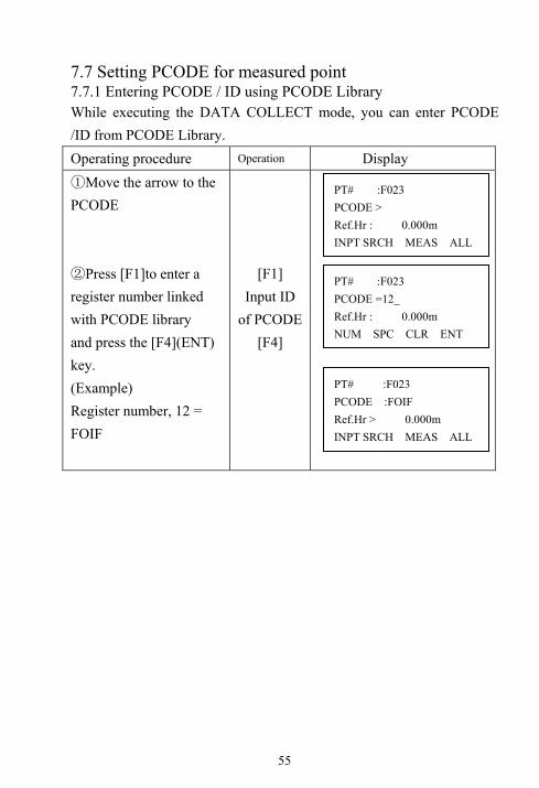
7.7 Setting PCODE for measured point 7.7.1 Entering PCODE / ID using PCODE Library While executing the DATA COLLECT mode, you can enter PCODE /ID from PCODE Library. Operating procedure Operation Display ①Move the arrow to the PCODE ②Press [F1]to enter a register number linked with PCODE library and press the [F4](ENT) key. (Example) Register number, 12 = FOIF
[F1] Input ID
of PCODE[F4]
PT# :F023 PCODE > Ref.Hr : 0.000m INPT SRCH MEAS ALL
PT# :F023 PCODE =12_ Ref.Hr : 0.000m NUM SPC CLR ENT
PT# :F023 PCODE :FOIF Ref.Hr > 0.000m INPT SRCH MEAS ALL

56
7.7.2 Entering PCODE / ID from the list of PCODE You can also enter PCODE / ID from the list of PCODE. Operating procedure Operation Display ①Move the arrow to the PCODE, press [F2](SRCH) ②By pressing the following keys, the registernumber will increase or decrease. [▲]or[▼]:Increasing or decreasing one by one [ ] or [ ]: By ten increasing or Decreasing. *1) Press [F4] (ENT) to confirm.
[F2]
[F4]
1※ )To edit the PCODE library, press the [F1](EDIT) key. To delete the PCODE registered with shown an arrow, press the [F3] (CLR) key. PCODE can be edited in DATA COLLECT menu 2/2 or MEMORY MANAGER menu 2/3.
PT# :F023 PCODE > Ref.Hr : 0.000m INPT SRCH MEAS ALL
>001:TREE
002:SYG EDIT --- CLR ENT
PT# :F023 PCODE >FOIF Ref.Hr > 0.000m INPT SRCH MEAS ALL
011:DKIID >012:FOIF 013:IOOF EDIT --- CLR ENT
57
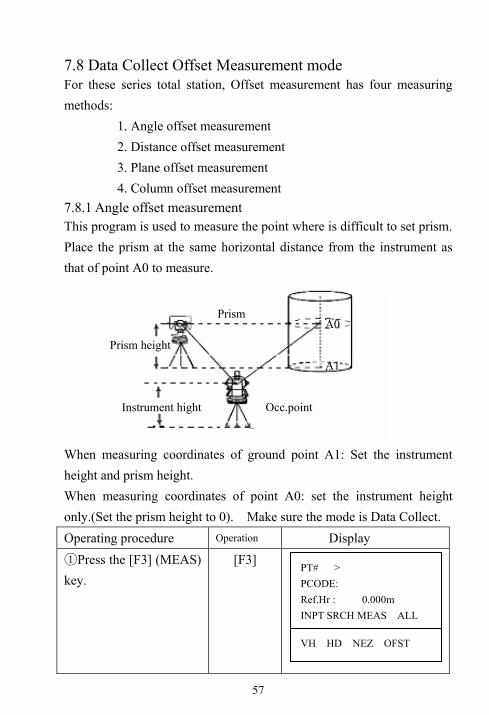
7.8 Data Collect Offset Measurement mode For these series total station, Offset measurement has four measuring methods: 1. Angle offset measurement 2. Distance offset measurement 3. Plane offset measurement 4. Column offset measurement 7.8.1 Angle offset measurement This program is used to measure the point where is difficult to set prism. Place the prism at the same horizontal distance from the instrument as that of point A0 to measure. When measuring coordinates of ground point A1: Set the instrument height and prism height. When measuring coordinates of point A0: set the instrument height only.(Set the prism height to 0). Make sure the mode is Data Collect. Operating procedure Operation Display
Press the [F3] (MEAS) ①
key.
[F3]
PT# > PCODE: Ref.Hr : 0.000m INPT SRCH MEAS ALL
VH HD NEZ OFST
A0
A1
Prism
Prism height
Instrument hight Occ.point

58
②Press the [F4] (OFST) key. ③Press the [F1] (angle offset). ④Collimate the prism, press [F3] to measure distance.
Collimate point A0 ⑤
using the horizontal motion clamp and horizontal tangent screw.
1※ ) Press [F3] (YES) to confirm, the measured data of A0 will be recorded.
[F4]
[F1]
Collimate
prism [F3]
Collimate
A0 [F3]
[F3]
1※ )The factory setting of display is horizontal distance, each time
pressing [ ] key, HD, VD, SD, N, E, Z are shown in sequence,
and recorded mode is displayed mode.
OFFSET 1/2 F1: ANG. OFFSET F2: DIST. OFFSET F3: PLANE OFFSET
ANGLE OFFSET HR: 120°30′40″ HD*[3] - > m <Measuring>
ANGLE OFFSET HR: 0°00′00″ HD m >OK? [YES] [NO]
PT# :F003 PCODE >0 Ref.Hr : 0.000m INPT SRCH MEAS ALL
ANGLE OFFSET HR: 120°30′40″ HD: m >Sight? YES NO

59
7.8.2 Distance Offset Measurement The measurement of an object point apart from a prism is possible by inputting offset horizontal distance of front or back/right or left. When measuring coordinates of ground point A1: set the instrument height and prism height. When measuring A0: set instrument height only. Make sure the mode is Data Collect. Operating procedure Operation Display ①Press the [F3] (MEAS) key ②Press the [F4] (OFST) key.
[F3]
[F4]
A0 A0
A1
Instrument height
Prism height
Occ.Point
Prism P
RorL HD
Forward HD
PT# :F003 PCODE >0 Ref.Hr : 0.000m INPT SRCH MEAS ALL
VH HD NEZ OFST
OFFSET 1/2 F1: ANG. OFFSET F2: DIST. OFFSET F3: PLANE OFFSET

60
③Press the [F2] key (DIST OFFSET). ④Enter Right or Left distance offset value; press [F4] to confirm. ⑤Enter forward distance offset value; press [F4] to confirm. ⑥Enter the PT#, PCODE, Ref.Hr. Collimate the prism, select measuring mode as distance or coordinate, and then begin measure distance.
Measured data is show⑧ n, press [F3] (YES) the data is recorded and the next measuring point is displayed.
[F2]
[F4]
[F4]
Collimate
prism SD
[F3]
DISTANCE OFFSET INPUT RorL HD oHD: m --- --- CLR ENT
DISTANCE OFFSET INPUT RorL HD oHD=1_
--- --- CLR ENT
PT# :F004 PCODE: Ref.Hr : 0.000m INPT SRCH MEAS ALL
PT# >F003 PCODE :M Ref.Hr : 1.000m --- SD COOR ---
DISTANCE OFFSET INPUT FORWARD HD oHD=2_ --- --- CLR ENT
VZ: 95°55′50″ HR: 117°17′22″ SD: 10.360m >OK? [YES] [NO]
61
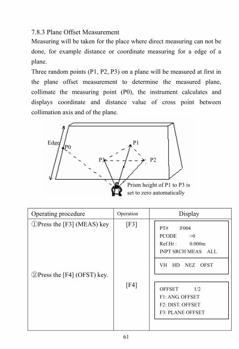
7.8.3 Plane Offset Measurement Measuring will be taken for the place where direct measuring can not be done, for example distance or coordinate measuring for a edge of a plane. Three random points (P1, P2, P3) on a plane will be measured at first in the plane offset measurement to determine the measured plane, collimate the measuring point (P0), the instrument calculates and displays coordinate and distance value of cross point between collimation axis and of the plane. Operating procedure Operation Display ①Press the [F3] (MEAS) key ②Press the [F4] (OFST) key.
[F3]
[F4]
P0 P1
P2 P3
Prism height of P1 to P3 is set to zero automatically
Edge
PT# :F004 PCODE >0 Ref.Hr : 0.000m INPT SRCH MEAS ALL
VH HD NEZ OFST
OFFSET 1/2 F1: ANG. OFFSET F2: DIST. OFFSET F3: PLANE OFFSET

62
Operating procedure Operation Display ③Press the [F3] key (plane offset). ④Collimate point P1, and
press the [F1] (MEAS) key to
measure. After measuring, the
display will show the second
point measurement. ⑤Collimate point P2, and
press the [F1] (MEAS) key to
measure. ⑥Collimate point P3, and
press the [F1] (MEAS) key to
measure. ⑦Collimate the point P0 on
plane edge. ⑧Press the F4 (MEAS) key,
the instrument calculates and
displays coordinate and
distance value of cross point
between collimation axis and
of the plane. 1※ ) 2※ )
⑨Press [ ] or [ ] to show
different display mode in
sequence. 3※ ) ⑩Press the [F3] (YES) key to
confirm and record, the display
returns to the next point
number in Plane Offset menu.
[F3]
Collimate P1
[F1]
Collimate P2
[F1]
Collimate P3
[F1]
Collimate P0
[F4]
PLANE N001# SD: m MEAS --- --- ---
LANE N002# SD: m MEAS --- --- ---
PLANE N003# SD: m MEAS --- --- ---
PLANE PT# >F004 PCODE: V INPT SRCH --- MEAS
HR : 12°34′56″ HD : 1.234m VD : 0.000m > OK? [YES] [NO]
N: 1.234m E: 1.234m Z: 1.234m > OK? [YES] [NO]
PLANE PT# >F005 PCODE: V INPT SRCH --- MEAS
63
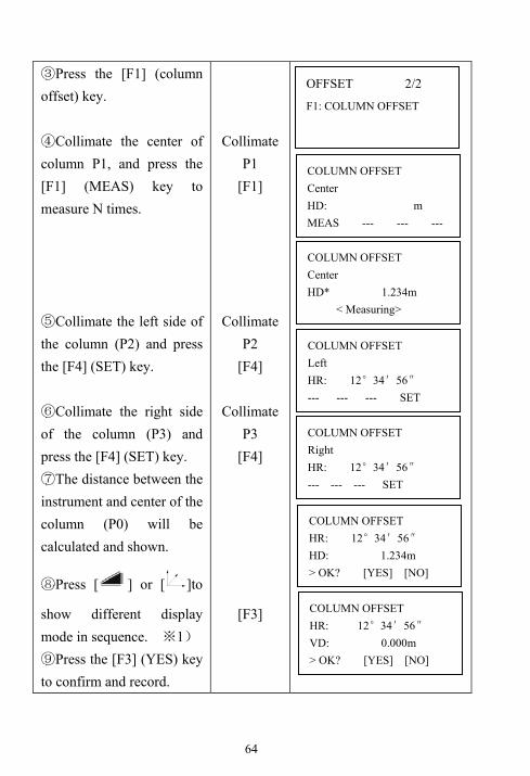
1※ )In case the calculation of plane was not successful by the measured three
points, error displays. Start measuring over again from the first point.
2※ )Error will be displayed when the collimated direction does not cross with the
determined plane.
3※ )Each time pressing [ ] or [ ] key, HD, VD, SD, N, E, Z are shown in
sequence, and the recorded mode is as displayed mode.
7.8.4 Column Offset Measurement It is possible to measure circumscription point (P1) of column directly, the distance to the center of the column (P0), coordinate and direction angle can be calculated by measuring circumscription points (P2) and (P3) The direction angle of the column center is average of circumscription points (P2) and (P3). Operating procedure Operation Display ①Press the [F3] key (MEAS) ②Press the [F4](OFST)
key, press [ ] key to
show next page.
[F3]
[F4] [EDM]
P1
P2
P3
P0
PT# :F005 PCODE >0 Ref.Hr : 0.000m INPT SRCH MEAS ALL
VH HD NEZ OFST
64
③Press the [F1] (column offset) key. ④Collimate the center of column P1, and press the [F1] (MEAS) key to measure N times. ⑤Collimate the left side of the column (P2) and press the [F4] (SET) key. ⑥Collimate the right side of the column (P3) and press the [F4] (SET) key. ⑦The distance between the instrument and center of the column (P0) will be calculated and shown.
⑧Press [ ] or [ ]to
show different display mode in sequence. 1※ )
⑨Press the [F3] (YES) key to confirm and record.
Collimate P1
[F1]
Collimate P2
[F4]
Collimate P3
[F4]
[F3]
COLUMN OFFSET Center HD: m MEAS --- --- ---
OFFSET 2/2
F1: COLUMN OFFSET
COLUMN OFFSET Center HD* 1.234m < Measuring>
COLUMN OFFSET Left HR: 12°34′56″ --- --- --- SET
COLUMN OFFSET Right HR: 12°34′56″ --- --- --- SET
COLUMN OFFSET HR: 12°34′56″ HD: 1.234m > OK? [YES] [NO]
COLUMN OFFSET HR: 12°34′56″ VD: 0.000m > OK? [YES] [NO]

65
1※ )Each time pressing [ ] or key, HD, VD, SD, N, E, Z are
shown in sequence, and the recorded mode is displayed mode. 7.9 NEZ Auto Calculation As measured data is collected, coordinates are calculated and stored for traverse or topo collection. Automatic making out function of coordinate data sets up in CONFIG of data collect. Refer to Section 7.10 “Setting Parameter of Data Collect [CONFIG.]”. As a default, coordinate data calculated will be saved in a file of the same name as the measurement data file. When the coordinate data file of the same name as the measurement data file does not exist, it wills be generated automatically. It is possible to change a file for saving coordinate data in the DATA COLLECT Menu 2/2 (F1: SELECT A FILE). To calculate a coordinate data, it is necessary to add a point number in Data Collect execution. When a coordinate data of the same point number exist already, it can be replaced with the new data by confirming display. ● Coordinates will be calculated using the grid factor. To set the grid factor, see Section 8.6“Setting the GRID FACTOR”

66
7.10 Setting Parameter of Data Collect [CONFIG.] In this mode, the following settings of data collect mode are possible ● Setting Items: Menu Selecting Item Contents F1:HD/SD HD/SD Select the distance measurement
mode Horizontal Distance or Slope distance.
F2:MEAS ORDER
N TIMES/S TIMES/REPEAT
Select to set measurement mode for distance measurement.
F3:DATA CONFIRM
YES/NO It is possible to confirm the result of measuring data before the data is recorded.
F1:COLLECT ORDER
Edit→Meas/ Meas→Edit
Select the procedure of data collection. [EDIT →MEAS]: Measurement is carried out after entering other data. [MEAS→EDIT]: Measurement is carried out before entering other data.
F2:NEZ AUTO.CALC
ON/OFF It is possible to calculate coordinate value of data collected and store it into coordinate data file in every data collection.

67
● How to Set items Example Setting: DATA CONFIRM: YES Operating procedure Operation Display ①The instrument in Data Collect mode. ②Press [▼] to enter collect menu 2/2. ③Press [F3] to show CONFIG menu. ④Press [F3] (DATA CONFIRM). ⑤Press [F1](YES) key, then press [F4] key to confirm.
[▼]
[F3]
[F3]
[F1] [F4]
COLLECT 1/2 F1: OCC.PT# INPUT F2: BACKSIGHT F3: FS/SS
COLLECT 2/2 F1:SELECT A FILE F2: PCODE INPUT F3:CONFIG
CONFIG F1: HD/SD F2: MEAS ORDER F3: DATA CONFIRM P↓
Data Confirm F1:YES [F2:NO] ENT
Data Confirm [F1:YES] F2:NO ENT

68
8. Coordinate Layout Layout mode has two functions which are setting of layout points and setting new points using coordinate data in the internal memory. Also, if the coordinate data is not stored in the internal memory, this can be input from key board. The coordinate data is loaded from PC to the internal memory via RS-232C or USB/SD card. The coordinate data The coordinate data is memorized into a file, the memory has three recorded parts, one is for measured data, another is for coordinate data, and the last one is for PCODE data. For the internal memory, refer to Chapter 10 “Memory Manager Mode”
8.1 Layout procedures 1) Selecting a file for layout.
2) Input Occ. point.
3) Input backsight point or backsight angle.
4) Input or pick-up (from internal memory) the coordinate data for
layout point. Start layout.
8.2 Selecting or creating a coordinate data file You can execute a Layout from selected coordinate date file. Here one existing coordinate data file can be selected; also you can input a new file name to create one new file for coordinate layout
1) When turning off the power, ensure that you are in the main menu screen or angle measurement mode. This ensures completion of the memory access process and avoids possible damage of the stored data. 2) It is recommended for safety to charge the battery beforehand and prepared fully charged spare batteries.

69
Operating procedure Operation Display ①Press [MENU] key, the instrument will be in MENU mode. ②Press [F2] key, to enter file selecting menu. ③Press [F2] key to display the list of coordinate data file.
1※ )※2) ④Scoll file list by pressing the [▲]or[▼ ]key and select a file to use.※3) ⑤Press [F4] key, the file will be selected. Instrument enters Layout Menu.
[MENU]
[F2]
[F1]
[ ▼ ] [F3]
1※ )If you want to input file name directly, press[F1]key to enter. ※2)If you input a file name that it is not found in memory, a new coordinate with input name will be created automatically. ※3)When a file has been selected already, mark .“@”is indicated on left of current file name. ● It is possible to select a file from Layout 2/2, menu in the same way.
MENU 1/3 F1: DATA COLLECT F2: LAYOUT F3: MEMORY MGR P↓
SELECT A CFILE FN: INPT LIST SKIP ENT
*1 /C0002 > 1SV /C0000 S /C0000 TOP LAST SRCH ENT
> *1 /C0002 1SV /C0000 TOP LAST SRCH ENT
Layout 1/2 F1: OCC. PT# INPUT F2: BACKSIGHT F3: LAYOUT P↓

70
8.3 Occupied Point Setting 1) Setting the coordinate data from the internal memory. Example: Confirm the coordinate data file has been selected already Operating procedure Operation Display ①The instrument be in LAYOUT mode. ②Press [F1] key. ③Press [F2] key. 1※ ) ④Press [▲] or [▼] key to select PT#. 2※ ) 3※ )
Press [F4] key to confirm. ⑤ Press [F3] key to select YES. ⑥Input Ins.Hi. Range:-999.999~ +999.999m Press [F4] key.
[F1]
[F2]
[F4]
[F3]
[F4]
1※ )Direct input PT#: Press [F1] key and input PT#. 2※ )The selected coordinate data can be viewed by press[F1](VIEW)
key. 3※ )The coordinate data can be searched by press[F2](SRCH).
Layout 1/2 F1: OCC. PT# INPUT F2: BACKSIGHT F3: LAYOUT P↓
OCC. PT PT# : INPT LIST NEZ ENT
> 2 1 VIEW SRCH --- ENT
N 5.620m E 4.210m Z 1.250m >OK? [YES] [NO]
INSTRUMENT HEIGHT INPUT Ins.Hi =1.000 m --- --- CLR ENT

71
2) Input the instrument point coordinates by hand Make sure the coordinate data file is selected. Operating procedure Operation Display ①Layout menu. ②Press [F1] key. ③Press [F3] (NEZ) key to coordinate inputting mode. ④Press [F1] key and enter N coordinate value; press [F4] to confirm. ※ 1) ⑤Enter E coordinate, press [F4] to confirm. ※ 2) ⑥Enter Z coordinate, and press [F4].
[F1]
[F3]
[F1]
[F4]
[F4]
[F4]
Layout 1/2 F1: OCC. PT# INPUT F2: BACKSIGHT F3: LAYOUT
OCC. PT PT# INPT LIST NEZ ENT
N > 0.000m E 0.000m Z 0.000m INPT --- PT ENT
N = 123.456_ m E : 0.000 m Z : 0.000 m --- --- CLR ENT
N: 123.456 m E= 987.65_ m Z : 0.000 m --- --- CLR ENT
N: 123.456 m E: 987.65 m Z= -1.608_ m --- --- CLR ENT

72
Operating procedure Operation Display
⑦ Press[F3](YES) key to record the inputted data to memory. ※ 1) ⑧ Input the PT# for input coordinate, press [F4] key. ⑨ Input the instrument height. Press [F4] key to confirm. ⑩ Back to Layout menu.
[F4]
Input PT# [F4]
Input
Instr.H [F4]
※1) The item following “<” is current inputting item. After the inputting
of this item press F4 to confirm, the mark “<”will move downward to
another item. Otherwise, press ▼ the cursor “<” will also move to other
item.
※2) If the setting of MANUAL NEZ REC is OFF at parameters menu, the
PT# inputting screen will not display, and the inputted coordinates isn’t
recorded to memory, and can not be recalled from memory in the future.
INTRUMENT HEIGHT INPUT Ins.Hi=1.5 _ --- --- CLR ENT
N: 123.456 m E: 987.65 m Z: -1.608 m
>REC ? [YES] [NO]
INPUT COORD PT# : INPT LIST --- ENT
Layout 1/2 F1: OCC. PT# INPUT F2: BACKSIGHT F3: LAYOUT
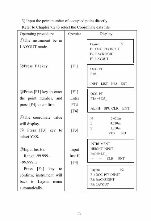
73
3) Input the point number of occupied point directly Refer to Chapter 7.2 to select the Coordinate data file
Operating procedure Operation Display ①The instrument be in LAYOUT mode. ②Press [F1] key. ③Press [F1] key to enter the point number, and press [F4] to confirm. ④The coordinate value will display. ⑤ Press [F3] key to select YES. ⑥Input Ins.Hi. Range:-99.999~ +99.999m Press [F4] key to confirm, instrument will back to Layout menu automatically.
[F1]
[F1] Enter PT# [F4]
[F3]
Input Inst.H [F4]
Layout 1/2 F1: OCC. PT# INPUT F2: BACKSIGHT F3: LAYOUT
OCC. PT PT# : INPT LIST NEZ ENT
OCC. PT PT# =F023_ ALPH SPC CLR ENT
N 5.620m E 4.210m Z 1.250m YES NO
INTRUMENT HEIGHT INPUT Ins.Hi=1.5 _ --- --- CLR ENT
Layout 1/2 F1: OCC. PT# INPUT F2: BACKSIGHT F3: LAYOUT

74
8.4 Setting Backsight Point 1) Setting the coordinate data file from the internal memory Make sure the instrument displays layout menu Operating procedure Operation Display ①Press [F2] (BACKSIGHT) key to set backsight point. ②Press [F2] key to view data file. 1※ ) 2※ ) ③Press [▲] or [▼] key to select PT#. Press [F4] key. ④The coordinate value will display. Press [F4] key to select YES. ※3) ⑤Collimate backsight, press [F3] key and return back the layout menu. ※4)
[F2]
[F2]
[▼] [F4]
[F4]
Collimate
backsight [F3]
1※ )Press [F1](VIEW) key the coordinate data values can be displayed.
2※ )Press [F2](SRCH) key the coordinate data can be searched by entering
PT#.
3※ )Press [F4](NO) key return to points list menu.
※4)Press[F2](dHD) to measure the difference between calculated backsight and true backsitht
BACKSIGHT PT# INPT LIST NEAZ ENT
> 2 1 VIEW SRCH --- ENT
N 1.000m E 2.000m Z 1.100m >OK? [ NO] [ YES]
BACKSIGHT HR:283°25′33″ >Sight?
--- dHD YES NO
Layout 1/2 F1: OCC. PT# INPUT F2: BACKSIGHT F3: LAYOUT P↓

75
2) Direct key input of coordinate data Make sure the instrument displays layout menu Operating procedure Operati
on Display
①Press [F2] key to enter backsight point setting screen. ②Press [F3] (NEAZ) key. 1※ ) ③Press [F1] key and enter N, E, Z coordinates in turns. Press [F4] key.
2※ ) ④Press [F3] key to record the input data. ⑤Press [F1] to input PT#, then press [F4] to confirm. ⑥Collimate backsight, press [F3]key and return back the layout menu. ※3)
[F2]
[F3]
[F1] [F4]
[F4]
[F3]
[F1] Input PT# [F4]
[F3]
1※ )With each pressing of [F3] key, switched among PT#, NEAZ (coordinate) and AZ (backsight angle).
BACKSIGHT PT# : INPT LIST NEAZ ENT
N > 0.000m E : 0.000m Z: 0.000m INPT ---- AZ ENT
N: 123.450m E: 987.640m Z= 564.230_ --- --- CLR ENT
INPUT COORD PT#: INPT LIST --- ENT
N: 123.450m E : 987.640m Z : 564.230 >REC ? [YES][NO]
BACKSIGHT HR:283°25′33″ >Sight?
dHD YES NO

76
※2) The item following “<” is current inputting item. After the inputting of
this item press F4 to confirm, the mark “<” will move downward to another
item. Otherwise, press ▼ the cursor “<” will also move to other item.
※3)Press[F2](dHD) to measure the difference between calculated backsight and true backsight. 3) Direct key input of setting angle. Make sure the instrument displays layout menu Operating procedure Operation Display ①Press [F2] key. ②Press[F3](NEAZ) key. 1※ )
③Press [F3] (AZ) key. ④Press [F1] key and enter setting angle. 123°16′18″ Press [F4] key. ⑤Collimate backsight, press [F3] key and return back the layout menu.
[F2]
[F3]
[F3]
[F1]
[123.1618] [F4]
Collimate
backsight
[F3]
1※ )With each pressing of [F3] key, switched among PT#, NE (coordinate) and AZ (backsight angle).
BACKSIGHT PT# : INPT LIST NEAZ ENT
N > 0.000m E: 0.000m Z: 0.000m INPT --- AZ ENT
BACKSIGHT HR: INPT ---- PT# ENT
BACKSIGHT HR =123.1618 --- --- CLR ENT
BACKSIGHT HR :123°16′18″ >Sight? YES NO

77
8.5 Executing a Layout The following methods can be selected for executing a layout. 1) Recalling points from internal memory by point number. 2) Direct key input of coordinate values. Example setting: recalling point from internal memory Operating procedure Operation Display ①Make sure the displaying is layout menu. ②Press [F3] (LAYOUT) key. ③Press [F2] (LIST) key. 1※ ) ④Press [▲] or [▼] key to select PT#. Press [F4] key.
2※ ) 3※ ) ⑤Press [F3] (YES) key to confirm the coordinate. 4※ )
⑥Input target height Ref.Hr. ⑦Press [F4] key. HR: calculated horizontal angle of the layout point HD: Calculated horizontal distance from the instrument
[F3]
[F2]
[F4]
[F3]
[F4]
Layout 1/2 F1: OCC. PT# INPUT F2: BACKSIGHT F3: LAYOUT P↓
LAYOUT PT# : INPT LIST NEZ ENT
[FOIFMA] > 2 1 VIEW SRCH --- ENT
N: 2.615m E: 3.186m Z: 1.268m >OK? [YES] [NO]
REF HT INPUT Ref.Hr=1.75_ --- --- CLR ENT
CACULATED HR: 44°38′29″ HD: 173.464m ANG DIST --- ---

78
to the layout point ⑧Collimate the prism, press [F1] (ANG) key. HR: measured(actual) horizontal angle dHR: Horizontal angle to be turned to the layout point=Actual horizontal angle-Calculated horizontal angle. Correct direction when dHR=0°00′00″ ⑨Press [F1] (DIST) key to measure distance. dHD: Measuring(Actual) horizontal distance dHD: Horizontal distance to be moved to the layout point=Actual horizontal distance-Calculated horizontal distance. dZ: Vertical distance to be moved to the layout point=Actual vertical distance-Calculated vertical distance. Press the [ESC] to stop measure.
[F1]
[F1]
[ESC]
PT# : HR : 44°38′29″ dHR: 30°38′29″ DIST --- CORD ---
dHR: 346°08′20″ dHD: -7.810 m dZ : - 0.022 m DIST MODE ANG NEXT

79
When the display value dHR, dHD and dZ are equal to 0, the layout point is established. ※4)※5) ○11 Press [F3] (ANG) key to setting screen, press [F3] (CORD) key again, the coordinate data is shown. Press [F2] mode key to setting the distance measuring mode. ○13 Press [F4] key to set next layout point.
[F3] [F3]
1※ )If you want to input PT# directly, press [F1]key and enter PT#. 2※ )The coordinate data can be viewed by press [F1]key.
※3)The coordinate data can be searched by press [F2]key and enter PT#. ※4)As normal, rotating the horizontal circle and make dHR reach 0. Setting the
prism as this direction. Make the dHD and dZ reach 0 by distance measured.
※5)Cut&Fill displaying function is available. Refer to Chapter 13 “Selecting Mode”.
NOTE: After layout, collimate the layout point and measure it’s coordinate, and
then confirm its accuracy, the measurement mode can be selected.
LAYOUT PT#: INPT LIST NEZ ENT
dHR: 000°00′12″ dHD: -0.001 m dZ : - 0.002 m DIST MODE ANG NEXT
PT# : HR : 44°38′29″ dHR: 30°38′29″ DIST --- CORD ---
N: 56.287 m E: 986.321 m Z: 123.345 m DIST MODE ANG NEXT

80
8.6 Setting the GRID FACTOR Calculation Formula 1. Elevation Factor = R/( R+ELEV)
R: The average radius of the earth ELEV. : The elevation above mean sea level 2. Scale Factor Scale Factor: Scale Factor at the surveying station 3. Grid Factor Grid Factor=Elevation Factor×Scale Factor Distance Calculation 1. Grid Distance HDg=HD ×Grid Factor HDg: Gird distance HD: Ground distance 2. Ground Distance
HD= HDg/ Grid Factor After the Grid Factor setting is finished, it is used for layout and other coordinate measurement programs. Operating procedure Operation Display ①Displayed the layout menu 2/2. ②Press [F2] key.
[F2]
Layout 2/2 F1: SELECT A FILE F2: GRID FACTOR
GRID FACTOR =1.000000
> MODIFY? YES NO

81
Operating procedure Operation Display ③Press [F3]key. 1※ ) ④Enter Elevation. 2※ ) Press [F4] to confirm. ⑤Enter Scale Factor. Press [F4]key. 3※ ) ⑥Press [F4] key. Grid Factor is displayed, and then returns to Layout menu automatically. 4※ )
[F3]
enter
Elevation [F4]
enter
Scale Factor
[F4]
1※ )Press[F4] key if don’t need to changed the Grid Factor. 2※ )Elevation enter range:-9999m ~ +9999m. 3※ )Scale enter range:0.990000 ~ 1.010000. 4※ )In Resection program, the Grid Factor need be reset to calculate the
error, refer to the procedures from step 2 to step 5 to do that.
GRID FACTOR ELEV. = 1000 m SCALE: 1.000000_ --- --- CLR ENT
GRID FACTOR ELEV. =0_ 0 m SCALE : 1.000000 --- --- CLR ENT
GRID FACTOR =1.000685

82
9. Application Measurement (Programs) 9.1 Remote Elevation Measurement (REM) Two mode of with prism and without prism can be selected to measure the vertical height from target to prism or ground point, the prism or ground point should be on the vertical line from the target. 1) With prism height (h) input (Example: h=1.5m) Operating procedure Operation Display ①Press the [MENU] key to menu mode. ②Press the [F1] (PROGRAMS) key.
[MENU]
[F1]
MENU 2/3 F1:PROGRAMS F2:PARAMETERS 1 F3:CONTRAST P↓
PROGRAMS 1/2 F1: REM F2: MLM F3: Z COORD
VD Prism
Prism height
Ground point G
Target K
Instrument

83
Operating procedure Operation Display ③Press the [F1] (REM) key to REM program. ④Press the [F1] key to select the first mode: INPUT R.HT. ⑤Enter prism height, press [F4] key to confirm. ⑥Collimate prism, press [F1] (MEAS) key to measure distance, the horizontal distance (HD) between instrument and prism will be shown. ⑦The vertical distance (VD) from prism to ground will be decided. ⑧Move telescope, the VD will upgrade in real-time. Collimate target, vertical distance (VD) from target to ground will be decided. ※1)
[F1]
[F1]
Enter R.HT [F4]
Collimate
P [F1]
Collimate target
※ 1)Press [F2](HT) to enter the new prism height. Press [F3] (HD) to
measuring the horizontal distance again.
To return to PROGRAMS Menu, press the [ESC] key.
REM-1 VD: 1.5 m --- HT HD ---
REM-1 VD: 1.602 m --- HT HD ---
REM F1: INPUT R.HT F2: NO R.HT
REM-1 <STEP-1> Ref.Hr 0.000m --- --- CLR ENT
REM-1 <STEP-2> HD: m MEAS --- --- ---
REM-1 <STEP-2> HD: * 21.232 m <Measuring>

84
2) Without prism height input Operating procedure Operation Display
Press the [MENU] key to ①
menu mode.
Press the [F1] (REM) ②
key.
Press the [F2] (NO ③
R.HT) key. Collimate prism④
Press the [F1] (MEAS) key, measuring starts, horizontal distance (HD) between instrument and prism will be decided. ⑤Vertical angle(VZ) will be shown
Press the [F4](SET) key.⑥
The prism position will be decided.
Collimate ground point ⑦
G. The position of point G will be decided. *1 ⑧Collimate target K. Vertical distance (VD) will be shown. *2
[F1]
[F2]
Collimate P
[F1]
[F4] Collimate
G [F4]
Collimate K
PROGRAMS 1/2 F1: REM F2: MLM F3: Z COORD
REM F1: INPUT R.HT F2: NO R.HT
REM-2 <STEP-1> HD: m MEAS --- --- ---
REM-1 <STEP-1> HD: * 6.888 m <Measuring>
REM-2 <STEP-2> VZ: 6°30'25" --- --- --- SET
REM-2 VD: 0.000m --- VZ HD ---
REM-2 VD: 6.580m --- VZ HD ---

85
*1) To return to procedure 4, press the [F3](HD) key. To return to procedure 5, press the [F2](VZ) key. *2) To return to PROGRAMS Menu, press the [ESC] key.
9.2 Missing Line Measurement (MLM) 9.2.1 Missing Line Measurement Measurement for horizontal distance (dHD), slope distance (dSD), elevation (dVD) between two targets. MLM has two modes: 1. MLM-1 (A-B, A-C): Measurement is A-B, A-C, A-D...... 2. MLM-2 (A-B, B-C): Measurement is A-B, B-C, C-D...... [Example]1. MLM-1 (A-B, A-C) Procedure of MLM-2 (A-B, B-C) mode same as MLM-1 mode Operating procedure Operation Display ①Press the [MENU] key to menu mode. ②Press the [F2] (MLM) key.
Press the [F1] or [F2] ③
key to select using
[F2]
[F2]
SD
HD
VD SD
VD HD
MLM-1 MLM-2
PROGRAMS 1/2 F1: REM F2: MLM F3: Z COORD
MLM F1:USE FILE F2:DON’ T USE

86
coordinate file. [Example:F2 : DON’T USE] ④Press the [F1] or [F2] key to select using GRID FACTOR. [Example:F2 :Not Use] ⑤ Press the [F1] key to select the first measure mode: MLM-1 A-B, A-C. ⑥Collimate A, press the [F1](MEAS) key to measure distance, 1※ ) ⑦Horizontal distance will display. ⑧Collimate B, press the [F1] (MEAS) key to measure distance ○9 Horizontal distance (dHD), relative elevation (dVD) and slope distance (dSD) between A and B can be shown.
[F2]
Collimate
A [F1]
Collimate
B [F1]
MLM-1(A-B, A-C) <STEP-1> HD: m MEAS RHT COOR ---
MLM-1(A-B, A-C) <STEP-2> HD: m MEAS RHT COOR SET
MLM-1(A-B, A-C) <STEP-1> HD:* 6.688m <Measuring>
MLM-1(A-B, A-C) <STEP-2> HD: * 2.380m <Measuring>
MLM-1(A-B, A-C) dHD: 5.726m dVD: 1.722m
--- --- COOR ---
MLM F1:MLM-1 A-B ,A-C F2:MLM-2 A-B,B-C
GRID FACTOR F1:Use F2:Not Use

87
To show slope distance (dSD), press [ ] key. Press [F3] (COOR), the coordinate of point B will display. ○10 To measure the distance between points A and C, Press the [F3] (HD). *1) Collimate point C (Prism C) and press the [F1] (MEAS) key. Horizontal distance (HD) between the instrument and prisms C will be shown. ※2)
⑾ To measure the distance between points A and D, repeat procedure 11. *1)
[F3]
Collimate
C [F1]
1)※ Press the [F2] key to input prism height.
※2) Press the [ESC] key to return to previous Menu.
MLM-1(A-B, A-C) dSD: 15.890m HR: 6°30'25"
--- --- COOR ---
MLM-1(A-B, A-C) <STEP-2> HD: m MEAS RHT COOR SET
MLM-1(A-B, A-C) <STEP-2> HD: * 16.536 m <Measuring>
N> -3.066m E: 32.430m Z: 8.796m INPT --- HD ENT

88
9.2.2 USE FILE and GRID FACTOR Operating procedure Operation Display
①Make sure the display is in [PROGRAMS] mode. ②Press the [F2] (MLM) key.
③ Press[F1](USE FILE) key ○4 Select a coordinate file. ○5 Press [F1] (F1:USE) to confirm. ○6 Press [F3] (YES) to confirm the Grid Factor.
⑦Repeat 9.2.1 step○4 -○10
[F2]
[F1]
[F4]
[F3]
PROGRAMS 1/2 F1: REM F2: MLM F3: Z COORD
MLM F1:USE FILE F2:DON’ T USE
SELECT A CFILE FN:1SV INPUT LIST --- ENT
GRID FACTOR F1: USE F2: Not Use
MLM F1:MLM-1 A-B ,A-C F2:MLM-2 A-B,B-C
GRID FACTOR
=1.0000000
>OK? [YES][NO]

89
9.2.3 Use coordinate for MLM program It is possible to input coordinate value directly or calculate from coordinate data file Operating procedure Operation Display To use coordinate data file, select “USE FILE” in step ③ of chapter 9.2.1. ①Press the [F3](COOR) key. Coordinate direct key input display will be shown.
③Press the [F3](PT#) key to use coordinate data file.Point number input display will be shown. Input the point number PT# or select coordinate in LIST. ④ Pressing the [F3](HD) key, the display will return to next point setting menu..
[F3]
[F3] Input
coordinate or PT#
[F4]
[F3]
N> 0.000m E: 0.000m Z: 0.000m INPT --- PT ENT
MLM-1(A-B, A-C) <STEP-1> HD: m MEAS RHT COOR ---
MLM-1 (A-B, A-C) PT#: INPT LIST HD ENT
MLM-1(A-B, A-C) <STEP-2> HD: m MEAS RHT COOR SET
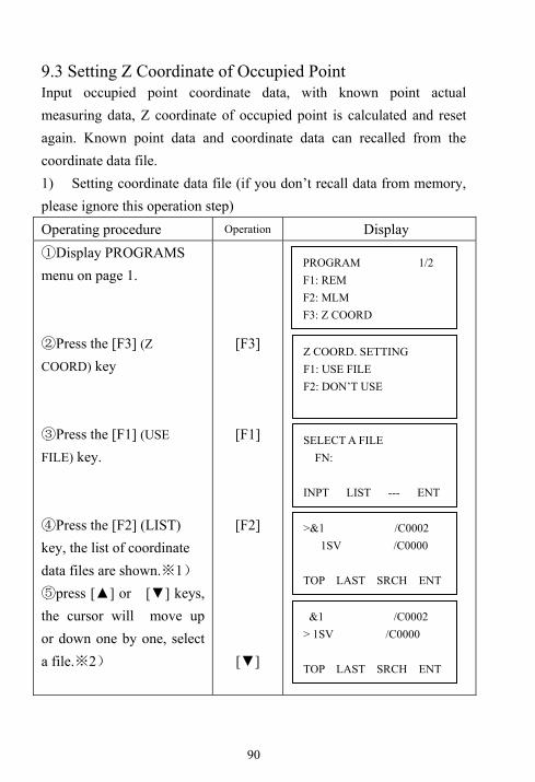
90
9.3 Setting Z Coordinate of Occupied Point Input occupied point coordinate data, with known point actual measuring data, Z coordinate of occupied point is calculated and reset again. Known point data and coordinate data can recalled from the coordinate data file. 1) Setting coordinate data file (if you don’t recall data from memory, please ignore this operation step) Operating procedure Operation Display ①Display PROGRAMS menu on page 1. ②Press the [F3] (Z
COORD) key ③Press the [F1] (USE
FILE) key. ④Press the [F2] (LIST) key, the list of coordinate data files are shown.※1) ⑤press [▲] or [▼] keys, the cursor will move up or down one by one, select a file.※2)
[F3]
[F1]
[F2]
[▼]
PROGRAM 1/2 F1: REM F2: MLM F3: Z COORD
Z COORD. SETTING F1: USE FILE F2: DON’T USE
SELECT A FILE FN: INPT LIST --- ENT
>&1 /C0002 1SV /C0000 TOP LAST SRCH ENT
&1 /C0002 > 1SV /C0000 TOP LAST SRCH ENT

91
⑥Press the [F4] key to confirm.
[F4]
1※ )Press the [F1](INPT) key to enter file name directly. 2※ )Press the [F3](SRCH) key to scan the coordinate data in the
selected file 2) Setting the Coordinate of occupied point Operating procedure Operation Display ①Make sure the displaying is in Z Coordinate mode ②Press the [F1] key(OCC.
PT INPUT) ③Press the [F2](LIST) key to display coordinates list.※1)※2) ④Press [▲] or [▼] keys, the cursor will move up or down one by one, select a point. Press the [F4] key to confirm※3) ⑤The coordinate value will be shown, press the [F3] (YES) key to confirm.⑥Input the instrument
[F1]
[F2]
[F4]
[F3]
Z COORD. SETTING F1: OCC. PT INPUT F2: REF. MEAS
Z COORD. SETTING F1: OCC. PT INPUT F2: REF. MEAS
OCC.PT PT#: INPT LIST NEZ ENT
>2 1 VIEW SRCH --- ENT
N: 1002.362m E: 566.231m Z: 100.002m >OK? YES NO
INSTRUMENT HEIGHT INPUT Ins.HT=1.000 m --- --- CLR ENT

92
height and press the [F4] to confirm.
Enter I.HT [F4]
※1) Press the [F1] (INPT) key to input point number directly. ※2) Press the [F3] (NEZ) key to input coordinate data directly. ※3) Press the [F1] (VIEW) key to scan the coordinate data in the selected file. 3) Z Coordinate Calculation from Known Point Measuring Data Example: Using coordinate data file Operating procedure Operation Display ①The display return to Z Coordinate program after selected the coordinate for occupied point. ②Press the [F2] key. (REF. MEAS) ③Press [F2] (LIST) key to open the data list, select a point, press [F3] (YES) to confirm. ④Press [F1](INPT) to input prism height R.HT Press [F4] to confirm.
[F2]
[F2] Select PT# [F3]
[F1] Input R.HT [F4]
N: 1002.362m E: 566.231m Z: 100.002m >OK? YES NO
Z COORD. SETTING F1: OCC. PT INPUT F2: REF. MEAS
N001# PT#: INPT LIST NEZ ENT
Z COORD. SETTING F1: OCC. PT INPUT F2: REF. MEAS
REF HT INPUT Ref.Hr=1.500_ m --- --- CLR ENT

93
⑤Collimate prism Press the [F3] (YES) key to start measure distance. ⑥Press the [F4] (CALC) key, the result will be shown. 1※ )Z:Z coordinate
dZ: standard error ⑦Press the [F4] (SET) key, the result will be set as the Z coordinate of occupied point. Backsight point measuring screen will be shown. 2※ ) ⑧If press the [F3](YES) key, azimuth angle will be set, the display returns to Z coordinate program mode
Collimate P [F3]
[F4]
[F4]
[F3]
1※ )Press the [F1](NEW) key to measure more points to improve precision,
repeat the steps from ② to ⑤ .
2※ )Pressing the [F3] key, the display will be changed alternately.
> Measuring…….
REF HT INPUT Ref. 1.5m > SIGHT? YES NO
BACK SIGHT HR: 180°00′00″ > Sight? YES NO
Z COORD. SETTING Z 12.345m dZ 0.000m --- --- BS SET
PROGRAM 1/2 F1: REM F2: MLM F3: Z COORD
HR: 142°23′59″ HD: 15.8m VD: 10.3m NEW --- --- CALC

94
9.4 Area Measurement This mode calculates the area of a closed figure. There are two area calculation methods as follows. 1) Area Calculation from Coordinate data file 2) Area Calculation from Measured data ● Area is not calculated correctly if enclosed lines cross each other. ● It is impossible to calculate what a mix of coordinate file data and measured data. ● If the coordinate data file does not exist, the area calculation from measured data is done automatically. ● The numbers of points used to calculate are not limited. 9.4.1 Area Calculation from Coordinate Data File Operating procedure Operation Display ①Enter PROGRAMS menu and press [F4] to enter page2. ②Press the [F1] (AREA) key. ○3 Press [F1] (KNOWN DATA) key ○4 Press the [F1] (INPUT) key and enter the file name. Initial display will be shown. The top of the file data is set as the first point of area automatically.
[F1]
[F1]
[F1] Enter the
File name [F4]
PROGRAMS 2/2 F1: AREA F2: POINT TO LINE F3: NEW POINT P↓
AREA F1:KNOWN DATA F2:MEASURE
SELECT A CFILE FN:FY_ INPT LIST --- ENT

95
⑤Press the [F4](NEXT) key. ※1), ※2) The top of the file data (F001) will be set and the second point number will be shown. ○6 Repeat pressing the [F4] (NEXT) key to set required number of points. When 3 or more points are set, the area surrounded by the points is calculated and the result will be shown. ※3)
[F4]
※1) To set specify point, press the [F1](PT) key. ※2) To show the list of the coordinate data in the file, press the [F2](CALL) key.
※3)Evey time press the [F3](UNIT) key to switch area unit. 9.4.2 Area Calculation from measured data
Operating procedure Operation Display
①Enter PROGRAMS menu and press [F4] to enter page2. ②Press the [F1](AREA) key.
[F1]
AREA 0000 m.sq NEXT PT:F001 PT CALL UNIT NEXT
PROGRAMS 2/2 F1: AREA F2: POINT TO LINE F3: NEW POINT P↓
AREA F1:KNOWN DATA F2:MEASURE
AREA 0001 m.sq NEXT PT:F002 PT CALL UNIT NEXT
AREA 0003 25.650 m.sq NEXT PT:F004 PT CALL UNIT NEXT

96
○3 Press [F2] (MEASURE) key. ○4 Press the [F1] or [F2] key to select using GRID FACTOR. [Example:F2 : DON’T USE] ○5 Collimate a prism and press the [F1] (MEAS) key. Measuring starts. ○6 Collimate next point and press the [F1] (MEAS) key. ○7 When 3 or more points are measured, the area surrounded by the points is calculated and the result will be shown. ※1)
[F1]
[F2]
[F4]
[F1]
※1)Evey time press the [F3](UNIT) key to switch area unit.
AREA F1:USE GRID FACTOR F2:NOT USE
AREA 0000 m.sq MEAS --- UNIT ---
N: 154.894m E: 45.685m Z: 10.588m <Measuring>
AREA 0001 m.sq MEAS --- UNIT ---
AREA 0003 56.741 m.sq MEAS --- UNIT ---

97
9.5 Point to Line This mode is used to obtain the relative coordinate data from the coordinate system: origin point A (0, 0, 0) and the line AB as N axis. Place the 2 prisms at the points A and B on the line, and place the instrument at unknown point C. After measuring the 2 Prisms, the coordinate data and the direction angle of the instrument will be calculated and restored. Operating procedure Operation Display
Make sure the displaying is ①
in Program menu on page2. ②Press the [F2] (POINT TO LINE) key. ③Enter instrument height Press the [F4] key to confirm.
[F2]
Enter INS.HT
[F4]
INSTRUMENT HEIGHT INPUT Ins.Hi= 1.750_ m --- --- CLR ENT
N Z
E
Prism P Point P2
B
Point P1
(0, 0, 0) A
PROGRAM 2/2 F1: AREA F2: POINT TO LINE F3: NEW POINT

98
④Enter the reflector height of Point A, [F4] (ENT) to confirm. ⑤Collimate Point A(P1), press the [F3] to measure. ⑥Enter reflector height of point B. Press the [F4] key to confirm . ⑦Collimate Point B (P2), press the [F3] to measure. ⑧The measured results will be shown. The coordinate data and direction angle of the instrument are calculated and restored. The result (the distance between A and B) will be displayed.
Enter
Ref.Hr[F4]
[F3]
Enter R.HT [F4]
Collima
te A [F3]
POINT TO LINE MEAS. P1 HD* 78.840 m < Measuring>
< Complete>
DIST. (P1-P2) 1/2 dHD: 8.080m dVD: 0.080m NEZ S.CO --- NP
REF HT INPUT Ref.Hr=2.500_ m --- --- CLR ENT
POINT TO LINE MEAS. P2 HD: m >SIGHT? YES NO
REF HT INPUT Ref..Hr 0.000m --- --- CLR ENT
POINT TO LINE MEAS. P1 HD: m >SIGHT? YES NO
POINT TO LINE MEAS. P1 HD:* 15.632 m <Measuring>

99
○9 Each time press the [F4] (NP) key, the result will be shown as HD, VD and SD in sequence. Press the [F2] (S.CO) key, the new coordinate of occupied point will be shown. The result will be shown. ○10 Press the [F1] (NEZ) key to measure other points. ○11 Collimate a prism and press the [F4] (MEAS) to start measure.
[F4]
[F1]
[F4]
N: 0.000m E: 0.000m Z: 0.000m EXIT --- HT MEAS
> Measuring...
N: 8.000m E: 1.000m Z: 0.080m EXIT --- HT MEAS
DIST. (P1-P2) 1/2 dS: 8.100m NEZ S.CO --- NP
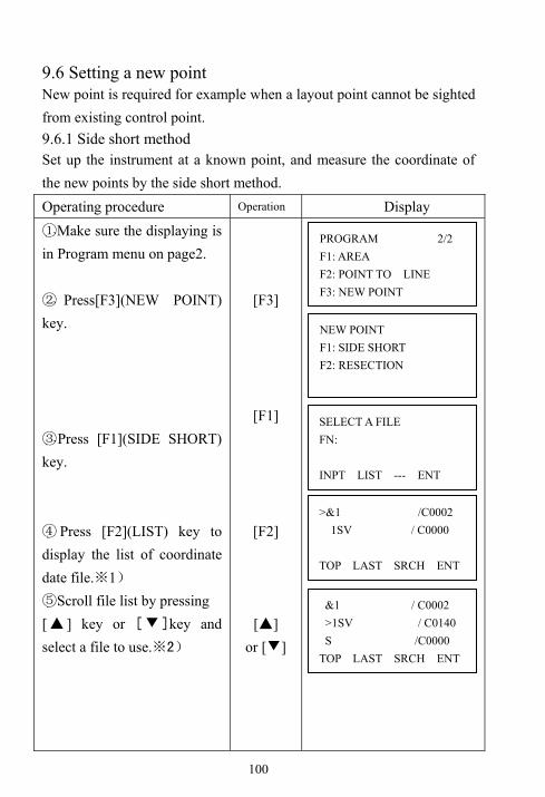
100
9.6 Setting a new point New point is required for example when a layout point cannot be sighted from existing control point. 9.6.1 Side short method Set up the instrument at a known point, and measure the coordinate of the new points by the side short method. Operating procedure Operation Display ①Make sure the displaying is in Program menu on page2.
② Press[F3](NEW POINT) key.
③Press [F1](SIDE SHORT) key.
④ Press [F2](LIST) key to display the list of coordinate date file.※1)
⑤Scroll file list by pressing [▲ ] key or [▼]key and select a file to use.※2)
[F3]
[F1]
[F2]
[▲] or [▼]
PROGRAM 2/2 F1: AREA F2: POINT TO LINE F3: NEW POINT
NEW POINT F1: SIDE SHORT F2: RESECTION
SELECT A FILE FN: INPT LIST --- ENT
>&1 /C0002 1SV / C0000 TOP LAST SRCH ENT
&1 / C0002 >1SV / C0140 S /C0000 TOP LAST SRCH ENT

101
⑥ Press the[F4](ENT) key. The file will be set. ⑦ Press the[F1] key , and enter the new point name PT#. Press the [F4] key.
Enter R.HT in the same ⑧
way.
Collimate the new point, ⑨
and press the [F3](YES) key to start measure distance.
⑩Press [F3](YES) key. The coordinate value is stored into COORD.DATA.file The input menu for next new point is displayed. PT# is automatically incremented
[F4]
[F1] Enter PT# [F4]
Enter
Ref.Hr [F4]
[F3]
[F3]
※1)Press [F1](INPT) key and enter a file name. ※2)The coordinate data can be searched by press[F3](SRCH) key.
< Complete >
SIDE SHOT PT#=F125_ NUM SPC CLR ENT
REFLECTOR HEIGHT INPUT Ref. 1.000 m >Sight? YES NO
HR: 12°34′56″ HD* < m VD: m >Measuring...
N: 56.287m E: 986.321 m Z: 123.345 m >REC? [YES] [NO]
REF HT INPUT Ref.Hr 0.000 m --- --- CLR ENT
SIDE SHOT PT#: F126 INPT SCRH --- ENT

102
9.6.2 Resection method Set up the instrument at a new point, and calculate the coordinate of the new point using the coordinate data of up to five known points and the measurements make to these points. By following observation, resection is possible: *Resection by distance measurement: 2 or more known points must be measured. * Resection by angle measurement only: 3 or more points must be measured NOTE: the new point can not be on the circum circle formed by the known points; otherwise the coordinate of new point is not correct.
Operating procedure Operation Display ①Make sure the displaying is in Program menu on page2. ② Press [F3](NEW POINT) key. ③Press [F2] (RESECTION)
[F3]
Known
Point A
Known
Point B Known
Point C Known D
(Max.5 points)
New point D
(Instrument)
PROGRAM 2/2 F1:AREA F2: POINT TO LINE F3: NEW POINT
NEW POINT F1: SIDE SHORT F2: RESECTION

103
key. ④ Select a coordinate file for known points. ⑤Enter the new point number. Press[F4] key.※1
⑥Enter the instrument height. Press [F4] key. ⑦Press[F1(INPT)]key and enter the known point 1. ※2
⑧Press F3(YES) to confirm the coordinate for point 1. ⑨Enter reflector height. Press [F4] key.
⑩Collimate the first known point 1, and press[F3] or [F4]key to select measuring mode. Measuring starts. ⑾The second known point B is waiting to confirm, entering display will be shown.
[F2]
PT# [F4] [F4]
INS.HT
[F4]
[F1] PT#
[F3]
R. HT [F4]
SKLECT A CFILE FN=FOIFMA_ ALPH SPC CLR ENT
NEW POINT PT#:45 INPT SRCH SKIP ENT
INSTRUMENT HEIGHT INPUT Ins.Hi=1.500_ m --- --- CLR ENT
N001# PT# INPT LIST NEZ ENT
REF HT INPUT
Ref.Hr=1.500_ m --- --- CLR ENT
N: 99.925m E: 56.369m Z: 9.563m REC? [YES] [NO]
REF HT INPUT Ref.Hr=1.500_ m >SIGHT? ANG DIST

104
⑿ Same as procedure ⑤ - ⑩proceed to the second known point 2. When two points have been measured, the RESIDUAL ERROR will be calculated.※3)⒀Select GRID FACTOR for calculation of RESIDUAL ERROR by pressing [F1] or [F2] key. ※3) Example: [F1] ⒁Press the [F1](NEXT) key to measure other points. Maximum five points can be measured. ⒂ Same as procedure ⑤-⑩ proceed to the known point 3. ⒃The measured value is displayed. Press the[F4](CALC) key. Standard error will be shown. ⒄Press the [F2](NP) key. Standard errors of each coordinate will be shown. The display will be changed alternately by pressing [F2] key. ⒅ Press the [F4](NEZ) key. Coordinate data of the new point will be shown.
[F1]
[F1]
[F4]
[F2]
[F4]
RESIDUAL ERROR dHD= 0.002m dZ = 0.003m NEXT --- G.F. CALC
HR: 1°23′45″ HD: 1.234 m VD: 0.001 m NEXT --- --- CALC
SD(n) = 1.234m SD(e) = 0.001m SD(z) = 0.000m -- NP --- NEZ
N: 1.234m E: 0.001m Z: 0.000m REC? [YES] [NO]
N002# PT# INPT LIST NEZ ENT
SET GRID FACTOR
F1:USE LAST DATA
F2:CALC MEASDATA
Standard Dev =2.01sec. --- NP --- NEZ

105
⒆Press the[F3](YES) key. The new point data will be stored into the coordinate data file and set as the current occupied point. ⒇ Press [F3](YES) to set the new point as occupied point, the last measured known point as backsight. The display returns to New Point menu. ※4)
[F3]
[F3]
※1)When there is no need to memorize the new point data, press the [F3](SKIP) key. ※2)To enter the known point coordinate data by direct key inputting, press the [F3](NEZ)key. ※3)RESIDUAL ERROR dHD(Horizontal distance between two known points)=Measured value-Calculated value dZ=(Z coordinate of the new point calculated from known point A)-(Z coordinate of the new point calculated from known point B) ※4)When [F3] key pressed in step 5, in this case, the new point data is not stored into the coordinate data file, only the value of occupied coordinate data changes to that of the calculated NEW POINT.
NEW POINT F1: SIDE SHORT F2: RESECTION
Resection Set Azimuth --- --- YES NO

106
10. Memory Manager Mode The following items for internal memory are available in this mode. 1) FILE STATUS: Checking the number of files or data in memory. 2) SEAECH: Searching and view point of memory. 3) FILE MAINTAN: Deleting files /Editing file name 4) COORD.INPUT: Inputting coordinate data to memory by keyboard. 5) DELETE COORD: Deleting coordinate data from memory. 6) PCODE INPUT: Inputting PCODE data into memory by keyboard. 7) COMM.PARAM.
SEND DATA: Sending measured data or coordinate data from instrument internal memory to other equipments.
RECEIVE DATA: Uploading measured data or coordinate data to total station internal memory. COMM PARAMENT: Communication parameters setting
8) INITIALIZE: Initializing internal memory, all the file and data will be cleared. 9) U Function: Enter the connecting interface between TS650 and PC by USB port 10.1 Enter Memory Manager Mode Operating procedure Operation Display ①Press the [MENU] key to enter menu mode.
②Press the [F3](MEMORY MGR.) key to enter memory manager mode. Press the [▲] or [▼] to turn page.
[MENU]
[F3]
MENU 1/2 F1: DATA COLLECT F2: LAYOUT F3:MEMORY MGR
MEMORY MGR. 1/3 F1: FILE STATUS F2: SEARCH F3: FILE MAINTAN P↓

107
10.2 Display Internal Memory Status Operating procedure Operation Display ①Make sure the displaying in Memory Manager mode on page1. ②Press the [F1] (FILE STATUS) key, the total number of stored Measured data files and Coordinate data files are shown. ③Press the [F4] (P) key to display the page 2, the total number of stored measured data and coordinate data are shown 1)※
[F1]
[F4]
1)※ Press the [F4] key to change the displaying status between files or data. 10.3 Searching data MEAS.DATA: Measured data. COORD.DATA: known coordinate data for layout or station setting PCODE Library: The data which was registered with a number from 0 to 49. 10.3.1 Measured data searching Operating procedure Operation Display ①Make sure the displaying mode in Memory Manager on page 1.
MEMORY MGR. 1/3 F1: FILE STATUS F2: SEARCH F3: FILE MAINTAN
MEMORY MGR. 1/3 F1: FILE STATUS F2: SEARCH F3: FILE MAINTAN
FILE STATUS 1/2 MEAS. FILE : 4 COORD. FILE : 7 [.............................] P↓
FILE STATUS 2/2 MEAS. DATA : 000460 COORD. DATA : 000450 [.............................] P↓

108
②Press the [F2] (SEARCH) key. ③Press the [F1] (MEAS.
DATA) key. ④Press the [F1] key to input file name. Press the [F4] key to confirm. ⑤Press the [F3](PT# DATA) key. 1※ ) ⑥Input PT#, press the [F4] to confirm, the point data will display in details. ⑦Press the [F4] key to turn page, other information of this point are shown. 2※ )※3)
[F2]
[F1]
[F1] Inputfile
name[F4]
[F3] Input PT# [F4]
[F4]
1※ )Press the [F1] key ,the first point data will be shown, press the [F2] key,
the last point data will be shown.
2※ )Press the [▲ ] or [▼] key to display previous or next point data.
※3)Press F1(EDIT) to edit the PT#, PCODE, or target height of this point.
SELECT A FILE FN:1 INPT LIST --- ENT
SEARCH F1: MEAS. DATA F2: COORD. DATA F3: PCODE LIB
MEAS. DATA SEARCH F1: FIRST DATA F2: LAST DATA F3: PT# DATA
PT# DATA SEARCH PT#=_ NUM SPC CLR ENT
PT#]1 1/3 N] 3713804.5836m E] 389849.825m Z] 959.514m ↓
PT#]1 3/3 PCODE] Ref.Hr] 1.680m EDIT ↓
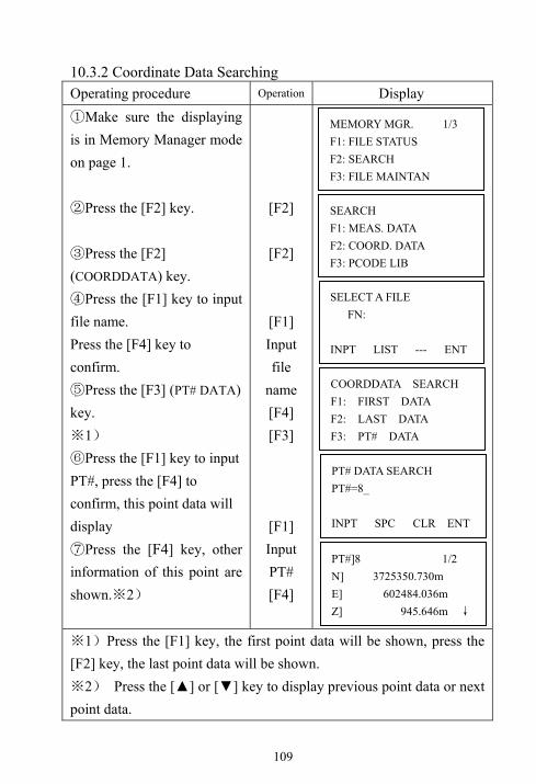
109
10.3.2 Coordinate Data Searching Operating procedure Operation Display ①Make sure the displaying is in Memory Manager mode on page 1. ②Press the [F2] key. ③Press the [F2] (COORDDATA) key. ④Press the [F1] key to input file name. Press the [F4] key to confirm. ⑤Press the [F3] (PT# DATA) key.
1※ ) ⑥Press the [F1] key to input PT#, press the [F4] to confirm, this point data will display ⑦Press the [F4] key, other information of this point are shown. 2※ )
[F2]
[F2]
[F1] Input file
name [F4] [F3]
[F1] Input PT# [F4]
1※ )Press the [F1] key, the first point data will be shown, press the [F2] key, the last point data will be shown.
2※ ) Press the [▲] or [▼] key to display previous point data or next point data.
SEARCH F1: MEAS. DATA F2: COORD. DATA F3: PCODE LIB
MEMORY MGR. 1/3 F1: FILE STATUS F2: SEARCH F3: FILE MAINTAN
SELECT A FILE FN: INPT LIST --- ENT
COORDDATA SEARCH F1: FIRST DATA F2: LAST DATA F3: PT# DATA
PT# DATA SEARCH PT#=8_ INPT SPC CLR ENT
PT#]8 1/2 N] 3725350.730m E] 602484.036m Z] 945.646m ↓

110
10.3.3 PCODE Library Searching Example searching: Number searching Operating procedure Operation Display ①Make sure the displaying is in Memory Manager mode on page 1. ②Press the [F2] key. ③Press the [F3] (PCODE LIB) key. ④Press the [F3](PT# DATA) key. 1※ ) ⑤Enter number. Press the [F4] key to confirm. 2※ )※3)
[F2]
[F3]
[F3]
[F1] Input
number[F4]
1※ )Press the [F1] key ,the first point data will be shown, press the [F2] key, the last point data will be shown.
2※ )Press the [ ▲] or [▼] key to display the previous or next PCODE, press the [F1] key to edit it, and press the [F3] key to delete this PCODE.※3)Press [F1](Edit) to edit this PCODE. Press [F3] (CLR) to delete this PCODE.
MEMORY MGR. 1/3 F1: FILE STATUS F2: SEARCH F3: FILE MAINTAN
SEARCH F1: MEAS. DATA F2: COORD. DATA F3: PCODE LIB
PCODEDATA SEARCH F1: FIRST DATA F2: LAST DATA F3: NO. SEARCH
> 009 : SYG 010 : FOIF 011 : GPS EDIT --- CLR ---
NO. SEARCH NO.=10_ --- --- CLR ENT

111
10.4 File Maintenance In this menu, the following items are available: Renaming file name, Searching data in a file and Deleting files, special symbols will be shown. (1) File discrimination mark (*, @). The mark (* or @) placed ahead file name indicates the file status. For measured data file: “*”means selected file for recording the measured data For coordinate data file: “*” means selected file for LAYOUT mode. “@” means selected coordinate file for DATA COLLECT mode. (2) Data type discrimination character (M, C) Data type discrimination character (M, C) placed before four figures indicate the type of data. “M” means measured data
“C” means known coordinate data (3) Four numbers following “M” or “C” means the recorded point quantity in the file. (4) This is a PCODE library in the memory. And it can record 50 PCODE in the library; the ID number of PCODE can be set from 01 to 50 freely.
>@FOIF_001 /C0008
*FOIF_002 /C0022
FOIF_003 /M0108
REN SRCH DEL ---
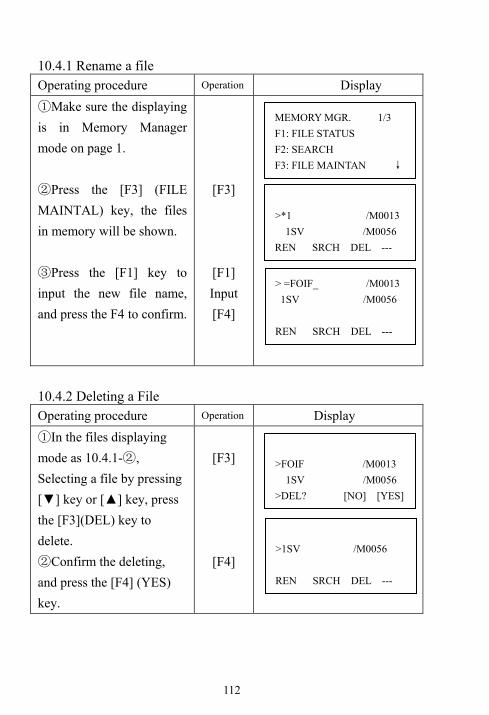
112
10.4.1 Rename a file Operating procedure Operation Display ①Make sure the displaying is in Memory Manager mode on page 1. ②Press the [F3] (FILE MAINTAL) key, the files in memory will be shown. ③Press the [F1] key to input the new file name, and press the F4 to confirm.
[F3]
[F1] Input [F4]
10.4.2 Deleting a File Operating procedure Operation Display ①In the files displaying mode as 10.4.1- , ②
Selecting a file by pressing [▼] key or [▲] key, press the [F3](DEL) key to delete. ②Confirm the deleting, and press the [F4] (YES) key.
[F3]
[F4]
>FOIF /M0013 1SV /M0056 >DEL? [NO] [YES]
>1SV /M0056 REN SRCH DEL ---
MEMORY MGR. 1/3 F1: FILE STATUS F2: SEARCH F3: FILE MAINTAN ↓
>*1 /M0013 1SV /M0056 REN SRCH DEL ---
> =FOIF_ /M0013 1SV /M0056 REN SRCH DEL ---
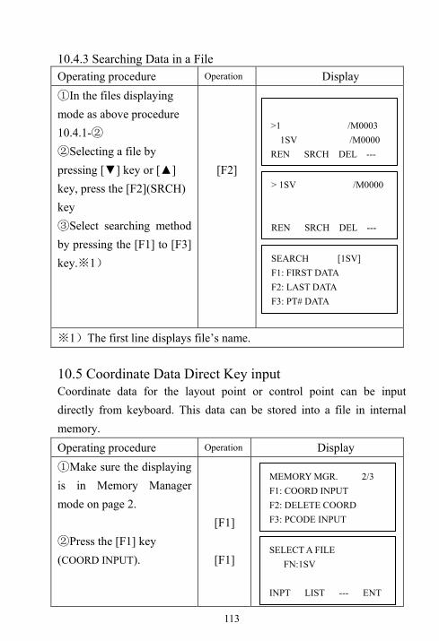
113
10.4.3 Searching Data in a File Operating procedure Operation Display ①In the files displaying mode as above procedure 10.4.1-② ②Selecting a file by pressing [▼] key or [▲] key, press the [F2](SRCH) key ③Select searching method by pressing the [F1] to [F3] key. 1※ )
[F2]
1※ )The first line displays file’s name. 10.5 Coordinate Data Direct Key input Coordinate data for the layout point or control point can be input directly from keyboard. This data can be stored into a file in internal memory. Operating procedure Operation Display ①Make sure the displaying is in Memory Manager mode on page 2. ②Press the [F1] key (COORD INPUT).
[F1]
[F1]
>1 /M0003 1SV /M0000 REN SRCH DEL ---
> 1SV /M0000 REN SRCH DEL ---
SEARCH [1SV] F1: FIRST DATA F2: LAST DATA F3: PT# DATA
MEMORY MGR. 2/3 F1: COORD INPUT F2: DELETE COORD F3: PCODE INPUT
SELECT A FILE FN:1SV INPT LIST --- ENT

114
③Press the [F1] key to input File name you want to input. Press the [F4] to confirm. ④Press the [F1] [INPT] key to input PT#. Press the [F4] to confirm. ⑤Input N coordinate data, press [F4] to confirm and move to E coordinate inputting status. After input Z, enter PCODE inputting menu, ⑥ Input PCODE, press F4, “complete” will display. Then next input display is shown. Point number (PT#) can increase automatically.⑦ Press the [ESC] to return.
Input file
name [F4]
[F1] Input PT# [F4]
[F1] Input Coord data [F4]
SELECT A CFILE FN=FOIF_ ALPH SPC CLR ENT
COORD DATA INPUT CODE: INPT LIST ---- ENT
COORD DATA INPUT PT#=1_ INPT LIST --- ENT
N=0.000 _ m E 0.000m Z 0.000m INPT --- ---
COORD DATA INPUT PT#:2 INPT LIST --- ENT
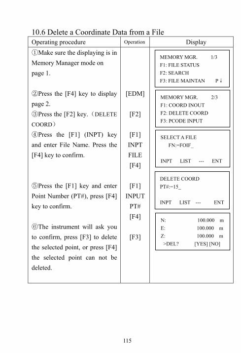
115
10.6 Delete a Coordinate Data from a File Operating procedure Operation Display ①Make sure the displaying is in Memory Manager mode on page 1. ②Press the [F4] key to display page 2. ③Press the [F2] key.(DELETE
COORD) ④Press the [F1] (INPT) key and enter File Name. Press the [F4] key to confirm. ⑤Press the [F1] key and enter Point Number (PT#), press [F4] key to confirm.
⑥The instrument will ask you to confirm, press [F3] to delete the selected point, or press [F4] the selected point can not be deleted.
[EDM]
[F2]
[F1] INPT FILE [F4]
[F1]
INPUT PT# [F4]
[F3]
MEMORY MGR. 1/3 F1: FILE STATUS F2: SEARCH F3: FILE MAINTAN P↓
MEMORY MGR. 2/3 F1: COORD INOUT F2: DELETE COORD F3: PCODE INPUT
SELECT A FILE FN:=FOIF_ INPT LIST --- ENT
DELETE COORD PT#:=15_ INPT LIST --- ENT
N: 100.000 m E: 100.000 m Z: 100.000 m >DEL? [YES] [NO]

116
10.7 Editing PCODE Library PCODE data can be entered into PCODE Library in this menu. A PCODE is linked with a number of 1 to 50. PCODE can be also edited in DATA COLLECT mode. Operating procedure Operation Display ①Make sure the displaying is in Memory Manager mode on page 1. ②Press the [▼] key once to display page 2. ③Press the [F3] (PCODE INPUT) key. ④By pressing the [▲] or [▼] keys to move the cursor. ⑤Press the [F1] (EDIT) key and input PCODE at current position of cursor, press the [F4] key to confirm.
[▼]
[F3]
[F1] [F4]
MEMORY MGR. 1/3 F1: FILE STATUS F2: SEARCH F3: FILE MAINTAN
MEMORY MGR. 2/3 F1: COORD INPUT F2: DELETE COORD F3: PCODE INPUT
>001: 12345678 002: SVYJMPADG EDIT --- CLR ---
001: 12345678 >002: SVYJMPADG 003: 1234567890 EDIT --- CLR ---
001: 12345678 >002= SVYJMPADG_ 003: 1234567890 ALPH SPC CLR ENT

117
10.8 Data Transfer by serial port The data in internal memory can be transferred to PC by RS232C serial cable D3-1000(Optional) directly. Before sending data, please connect instrument and PC correctly with RS-232C cable, and the communication settings of instrument are same as PC’s settings. The data in instrument memory can be downloading to PC, also the data can be uploaded from PC to instrument memory. 10.8.1 Sending data Example: sending a measured data file. Operating procedure Operation Display ①Make sure the displaying is in Memory Manager mode on page 3. ②Press[F1](COMM.PARAM) key. ③ Select data format. F1: GTS: Normal format F2: SSS: With code. ④Press the [F1] (SEND DATA) key.
[F1]
[F1]
[F1]
Data Com. F1: SEND DATA F2: RECEIVE DATA F3: COMM PARAMENT
Data Com F1:GTS F2:SSS
MEMORY MGR. 3/3 F1: COMM.PARAM. F2: INITIALIZE F3: U Function P↓
D3-1000 serial cable (Optional)

118
Press [F1] (MEAS.DATA) key. ⑤Press the [F1] key to input File Name, press the [F4] key to confirm. ⑥ After the receiving equipment (PC) is ready, press the [F3] (YES) to confirm, the sent point quantity will display in real-time, press F4 (STOP) to stop data sending.
[F1]
[F1] Input
File Data[F4]
[F3]
10.8.2 Loading data Example: Loading a coordinate data file to TS650 memory Operating procedure Operation Display ① Following steps ① to ③ of “10.8.1 Sending data”. ②Press the [F2] (RECEIVE DATA).
③Press [F1] (COORDDATA) key.
[F2]
[F1]
SEND DATA F1: MEAS. DATA F2: COORD.DATA F3: PCODE DATA
SELECT A FILE FN=FOIF_ ALPH SPC CLR ENT
SEND MEAS. DATA >OK? --- --- YES NO
SEND MEAS. DATA 88 --- --- --- STOP
Data Com. F1: SEND DATA F2: RECEIVE DATA F3: COMM PARAMENT

119
④Press the [F1] key to input File Name, press the [F4] key to confirm. ⑤If the cable connection between TS650 and PC is ready, press F3(YES) to confirm. ⑥Operate on the PC software, begin sending data from PC to TS650. Press F4 (STOP) to stop data receiving.
[F1] Input
File Data [F4]
[F3]
10.8.3 Setting parameter of data communications Items of the Parameter Item Selecting item Content F1: Protocol
[ACK/NAK]/[NO] Setting Protocol [ACK/NAK] or [NO] communication
F2: Baud rate
1200/2400/4800/ 9600/19200/38400
Setting transfer speed 1200/2400/4800/9600/19200 /38400 baud rate
F3: Char. / Parity
[7/EVEN]/ [7/ODD]/ [8/NON]
Setting data length and parity: [7bit, even], [7bit, odd], or [8bit,none]
F1: Stop Bits 1, 2 Setting Stop 1 bit or 2bits
LOAD DATA <Waiting Load !> --- --- --- STOP
LOAD DATA F1: COORDDATA F2: PCODE LIB
COORD FILE NAME FN=FOIF_ ALPH SPC CLR ENT

120
10.9 Memory initialize Delete all the files or clear the whole memory. Example: Delete all the measured data files Operating procedure Operation Display ①Make sure the displaying is in Memory Manager mode on page 3. ②Press [F2] (INITIALIZE) key. ③ Select the option you can to clear. MEAS FILES, clear all measured files COORD FILES, clear all coordinate files PCODE FIELS, clear all PCODEs Format, the whole memory will be clear. ④Press the [F3] (YES) key, all coordinate data files will be deleted. It returns to previous menu automatically.
[F2]
[F2]
[F3]
Warning: All the deleted files and data can not be restored.
INITIALIZE Delete
Coord Files? ---- --- [YES] [NO]
INITIALIZE F1:MEAS FILES F2:COORD FILES F3:PCODE FILES P↓
INITIALIZE F1:MEAS FILES F2:COORD FILES F3:PCODE FILES P↓
MEMORY MGR. 3/3 F1: COMM.PARAM. F2: INITIALIZE F3: U Function P↓

121
10.10 Connect PC via USB port For TS650 USB cable D30-2200 is standard data transfer cable, you can connect TS650 and PC by D30-2200 directly, no driver program need. Of course if your TS650 equipped with USB port, you can use standard USB cable to connect TS650 with PC for data transferring. The data transferring procedures are same for D30-2200 cable and standard USB cable.
D30-2200 USB cable
SD card slot
Optional equipment
Standard equipment
Mini USB port

122
Operating procedure Operation Display ①Make sure the displaying is in Memory Manager mode on page 3. ②Press [F3] (U Function) key. ③Connect instrument and PC via D30-2200 cable or standard USB cable, TS650 will display “U FUNCTION Press ESC exit”. 1※ ) It means the TS650 is connected with PC already. Press [ESC] to disconnect them, and the instrument back to previous menu.
[F3]
[F2]
[ESC]
1※ )After TS650 is connecting with PC, the data folder in memory will open automatically, with FOIFExhange software to view the data.
U Function Press ESC exit
MEMORY MGR. 3/3 F1: COMM.PARAM. F2: INITIALIZE F3: U Function P↓
U Function Plug the USB Press ESC exit
MEMORY MGR. 3/3 F1: COMM.PARAM. F2: INITIALIZE F3: U Function P↓

123
10.11 Copy the data files from memory to SD card (Optional) If you TS650 is equipped with SD card module, you can copy the data files from internal memory to SD card. Example: Transferring all measured data files to SD card. Operating procedure Operation Display ①Enter Menu mode on page 3. Press [F3] (SD COPY) to enter copying menu. ②Press [F1] (MEAS.DATA) key. The entire measured data file will be transferred from internal memory to SD card. At last back to previous menu automatically.
[F3]
[F1]
Copying……
SD COPY F1:MEAS.DATA F2:COORD.DATA F3: All Files
MENU 3/3 F1: CONTRAST F2: COM MODE F3: SD COPY P↓
MENU 3/3 F1: CONTRAST F2: COM MODE F3: SD COPY P↓

124
10.12 Connect TS650 with other device via Bluetooth (Optional) If you TS650 is equipped with Bluetooth module, you can connect it with other device via wireless communication Operating procedure Operation Display ①Enter Menu mode on page 3. ②Press [F2] (COM MODE) key. ③Press [F2] (BLUE TOOTH), press [F4] to confirm. ④Press [ESC] back to basic measurement mode. You will see the Bluetooth mark on the screen right. Now use you device to search the TS650 for communication.
[F2]
[F2] [F4]
[ESC]
MENU 3/3 F1: CONTRAST F2: COM MODE F3: SD COPY P↓
Com Mode [F1:RS-232C] F2:BLUETOOTH
ENT
MENU 3/3 F1: CONTRAST F2: COM MODE F3: SD COPY P↓
VZ: 81° 54′ 21″ HR: 157° 33′ 58″
0SET HOLD HSET P1
VZ: 81° 54′ 21″ HR: 157° 33′ 58″
0SET HOLD HSET P1

125
11. Instrument Settings In the parameters menu 1, there are some normal used settings, they are normal
used for measurement.
11.1 Items of instrument settings
MENU 2/3 F1: PROGRAMS F2:PARAMETERS1 F3:CONTRAST P↓
PARAMETERS 1/2F1: MIN ANG READING F2: AUTO OFF F3: TILT
PARAMETERS 2/2F1: RS-232C
P↓
F2
F4
F1
RS-232C 3/3 F1: Factory Set
P↓
RS-232C 1/3 F1:BAUD RATE F2:CHAR./PARITY F3:STOP BIT P↓
RS-232C 2/3 F1:ACK F2:CR,LF REC MODE P↓

126
(* factory setting) Menu Display
Optional Content
1″/0.2mgon* The min angle reading is 1″/0.2mgon
5″/1mgon The min angle reading is 5″/1mgon
MIN ANG
READING
10″/2mgon The min angle reading is 10″/2mgon
10M/30M After 10 or 30 minutes without any
operation, power will auto-off
AUTO OFF
OFF * auto-off isn’t active
OFF The tilt sensor is OFF TILT
ON * The tilt sensor is ON
BAUD
RATE
1200* 2400 4800
9600 19200 38400
7/EVEN 7 Data length, even parity
7/ODD 7 Data length, odd parity
CHAR.
/PARITY
8/NONE* 8 Data length, no parity
1 * One stop bit STOP
BIT 2 Two stop bit
Standard Communication way:
double-action
ACK
Omitted * Communication way:
single-action
ON With carriage return CR,LF
OFF * Without carriage return
REC-A* Measuring and output
measured data
REC
MODE
REC-B Output displayed data
RS-232C
Factory Set Recall factory setting

127
11.2 Enter setting mode Operating procedure Operation Display ①Make sure the displaying is menu mode on page 2. ②Press the [F2] (PARAMETERS) key.
[F2]
11.3 Setting procedures Example: change the minimum reading from 1″ to 5″. Operating procedure Operation Display ①Make sure the displaying is PARAMETERS menu on page 1. ②Press the [F1] key, the current setting will be shown in the“[ ]”. ③Press the [F2]( 5″) key, press the [F4] to confirm.
[F1]
[F2] [F4]
PARAMETERS 1/2F1: MIN ANG READING F2: AUTO OFF F3: TILT
PARAMETERS 1 1/2F1: MIN ANG READING F2: AUTO OFF F3: TILT
PARAMETERS 1/2 F1:MIN ANG READREADING F2: AUTO OFF F3:TILT P↓
MinANGLE [F1: 1”] F2: 5” F3: 10” ENT
MinANGLE F1: 1”
[F2: 5”] F3: 10” ENT

128
12. Selecting Mode 12.1 Items of selecting mode The following modes are available
Menu Items Selecting item
Display
F1:Temperature ℃/℉ Select the unit of temperature for atmospheric correction
F2:Pressure hPa/mmHg/inHg/psi/ mbar
Select the unit of air pressure for atmospheric correction
F3:ANGLE DMS(360°)/GON(400G)/MIL(6400M)
Choose degree, gon or mil unit for measuring angle
F1:Dist M/Ft/Ftin Choose measuring unit for distance meter, feet or feet and inch
F1: Unit
F2:Feet US_feet/ IN_feet
Select the meter/feet conversion factor US SURVEY feet 1m=3.280833333333333ft INTERNATIONAL feet 1m=3.280839895013123ft
F1:Power On
Mode
Angle/Dist Select to set the measurement mode for angle or distance when the power is turned on
F2:Fine/Track Fine/Tracking Select Fine/Tracking mode in distance measurement mode, when the power is turned on
F2:
Mode
F3:HD/SD HD&VZ/SD Specify which is displayed first, horizontal and vertical distance or slope distance, when the power is turned on

129
F1:Z0/H0 VZ0/HA0 Choose the vertical angle reading from zenith or from level
F2:NTIMES/
REPEAT
N TIMES/
REPEAT
Select the measurement mode for distance when the power is turned on
F3:MEAS
TIMES
0-99 Set N (number of times) for times of distance measurement. When setting number of times as 1, it is single measurement
F1:NEZ/ENZ NEZ/ENZ Select a coordinate
displaying order either NEZ
or ENZ
F2:Offset VA Free /Hold Select Vertical angle setting in the Angle Offset measurement mode. FREE: Vertical angle varies by the angle of the telescope.HOLD: Vertical angle is fixed even if the angle of the telescope changes.
F2:
Mode
F3:ESC MODE Collect/SO
/Rec/OFF
You can select a function of the [ESC] key. DATA COLLECT/ LAYOUT: It is possible to enter data input mode (in DATA COLLECT) or Layout Menu from normal measuring mode directly. REC: While executing normal or offset measuring, the measuring data can be output. OFF: Returns to normal function

130
F1:Coor Check ON/OFF Select coordinate displaying ON or OFF when setting a point
F2:EDMOff
Time
0-99 The time when EDM is cut off from distance measurement is completed can be changed. This function is effective for shortening time measuring time when distance measurement is started from distance measurement completing state. Default:3minutes) 0 :After completing distance measurement, EDM is cut off immediately.1-99: EDM is cut off after 1~99 minutes.
F2:
Mode
F3:Read Min 0.2mm/1mm Select 1mm or 0.2mm for the minimum reading unit in the distance mode (FINE mode)
F1:HA Buzzer ON/OFF Specify whether the buzzer sounds or not for every horizontal angle 90°
F2:Signal Buzzer ON/OFF Specify whether the buzzer sounds or not in the set audio mode.
F3:
Other
F3:K select
0.14/0.20/OFF
Set correction for refraction and earth curvature, efficient of refraction as ; K=0.14, K=0.20 or no correction

131
F1:Coor Rec ON/OFF It is possible to retain the
coordinate of instrument
point, the instrument height
and prism height after power
off.
F2:Rec Type REC-A/
REC-B
Select REC-A or REC-B for
data output
REC-A: The measurement is
made again and this new
data is output.
REC-B: The data being
displayed is output
F3:CR,LF ON/OFF It is possible to output the data with carriage return and line feed.
F1:NEZ Rec Standard12/
WithMeas12
Select to record coordinates in standard or 11 digits with raw data
F2:InputCoor Re ON/OFF In the layout mode or data collect mode, it is possible to record coordinates entered directly from the keyboard
F3:ACK Standard/Omi
tted
Set the procedure of the communication with external device. STANDARD: Normal procedure OMITTED: Even though the [ACK] is omitted from the external device, the data is sent again
F3:
Other
F1:
GRID FACTOR
Use/Not Use Select using GRID FACTOR in calculation of measurement data

132
F2:Cut Or Fill Standard/Cut
&Fill
In the layout mode, CUT & FILL can be displayed instead of dZ
F3:Back Disp ON/OFF It is possible to output the data of echo back type
F1:Contrast men ON/OFF When the instrument is turned ON, it is possible to display the screen which you can adjust contrast of the display and confirm the prism constant (PSM) and atmospheric correction value (PPM)
F2:LANGUAGE ENGLISH/
OTHER
Select the displaying language.
F3:
Other
F3:Key Buzzer ON/OFF Setting the key pressing buzzer ON/OFF
12.2 How to set selecting mode <Example>: Setting unit in °F, NEZ MEMORY:ON Operating procedure Operation Display ① While pressing F2 key,
turn Power ON
②Press the [F1] key, the current setting will be shown in the“[ ]”. ③Press [F2](℉) key, and press[F4](ENTER) key.
F2
+
Power on
[F1]
[F2]
[F4]
PARAMENT 2 F1:UNIT F2:Mode F3:Other
Unit 1/2 F1: Temperature F2: Pressure F3:Angle P↓
Temp. Unit [℃] ℃ ℉ ENT

133
Operating procedure Operation Display Press [ESC] key.④
Returns to PARAMETERS 2
menu.
⑤ Press [F3] (OTHERS SET)
key.
Press [F4] (P↓) key, to get the ⑥
function in page 2.
⑦Press [F1] key.
⑧Press [F1](ON) key, and press [F4] (ENTER) key. Returns to OTHERS SET menu. ⑨Power off
[ESC]
[F3]
[F4]
[F1]
[F1] [ENT]
Other 2/5 F1:Coor Rec F2:Rec Type F3:CR,LF P↓
Coor Rec [OFF] ON OFF [ENT]
Other 2/5 F1:Coor Rec F2:Rec Type F3:CR,LF P↓
Other 1/5 F1:HA Buzzer F2:Signal Buzzer F3:K Select P↓
PARAMENT 2 F1:UNIT F2:Mode F3:Other

134
13. Check and adjustment 13.1 Checking and adjusting of instrument constant Instrument constant means additive constant for distance measurement. Normally, the instrument constant doesn’t have error. It is recommended you measure and compare with an accurately measured baseline one consistent ground. If such a baseline is not available, establish your own base line over 20m and compare the data measured with the newly purchased instrument. In case, the instrument setup, the prism, baseline precision, poor collimation, atmospheric correction, correction for refraction and earth curvature determine the inspection precision. Also, when providing a base line indoor, the following procedure as shown below could be used to check the instrument constant. (1) Provide point B on a straight line AC, which is almost level and about 100m long. Measure straight lines AB, AC and BC.
(2) Obtain the instrument constant by repeat measurement, Instrument constant =AB+BC-AC (3) When there is error between written instrument constant value and calculated value, only need to synthesize the instrument constant and prism constant, and then input the synthesized data in prism constant form, please refer to“7.3.1 Setting of the prism constant”. (4) Once again, measure at a calibrated baseline and compare results. (5)If using above procedure a difference of over 5mm is found, the instrument constant need reset as the operating procedure on next page.
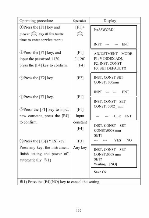
135
Operating procedure Operation Display ①Press the [F1] key and power [①] key at the same time to enter service menu. ②Press the [F1] key, and input the password 1120, press the [F4] key to confirm. ③Press the [F2] key. ④Press the [F1] key. ⑤Press the [F1] key to input new constant, press the [F4] to confirm. ⑥Press the [F3] (YES) key. Press any key, the instrument finish setting and power off automatically. ※1)
[F1]+ [ ]①
[F1] [1120]
[F4]
[F2]
[F1]
[F1] input
constant[F4]
[F3]
Any key
※1) Press the [F4](NO) key to cancel the setting.
PASSWORD INPT --- --- ENT
ADJUSTMENT MODE F1: V INDEX ADJ. F2: INST. CONST F3: SET DEFAULT!!
INST. CONST SET CONST: 000mm INPT --- --- ENT
INST. CONST SET CONST: 0002_ mm --- --- CLR ENT
INST. CONST SET CONST:0008 mm SET? --- --- YES NO
INST. CONST SET CONST:0008 mm SET? Waiting... [NO]
Save Ok!

136
13.2 Checking/adjusting the plate level (1) Set the instrument on stable device (such as tripod or adjusting table) and fix it. (2) Level the instrument roughly, place the plate level parallel to a join-line of two leveling screws, say, A and B. Use these two leveling screws only and place the bubble in the center of the plate level. (3) Rotate the instrument 180°and check bubble movement of the plate level. If the bubble has always been in the center of the plate level, then it is not needed to adjust. If the bubble has been displaced (deviate the center away half of one grid), then adjust it. Adjustment (1) Set the instrument on stable device and fix it. (2) Level the instrument roughly. (3) Place the plate level parallel to a join-line of two leveling screws. Use these two leveling screws only and place the bubble in the center of the plate level. (4) Rotate the instrument 180°. When the bubble stable, adjust the level adjustment screw with the adjusting pin and return the bubble towards the center of the plate level. Correct only one-half of the displacement by this method. (5) Repeat the procedures of (3) and (4) until anywhere the instrument moves to, the bubble will always be in the center of the plate level.
Screw C
Screw BScrew A
Plate level
Bubble
Mark Bubble
Adj-screw
Turn the instrument 180°

137
13.3 Checking/adjusting the circular level Check (1)Set the instrument on stable device and fix it; (2)Precisely level the instrument with the plate level; (3)Look the bubble of the circular level whether is in the center; if the bubble is centered properly, adjustment is not required. Otherwise, adjust it. Adjustment (1)Set the instrument on stable device and fix it; (2)Precisely level the instrument with the plate level; (3)Shift the bubble to the center of the circular level, by adjusting two adjustment screws with the adjusting pin. NOTE: When adjust with pin, you should do that with smaller strength, the loose-tight degree of two screws should be similar.
Adjusting screw
Circle bubble

138
13.4 Checking/adjusting the optical sight Check (1) Set the instrument on stable device and fix it; (2) Set a cross mark front the instrument
50m apart; (3) Let the telescope collimate the
cross mark; (4) Observe the optional sight collimator
whether collimating the cross mark, if collimates the mark, adjusting is not required. Otherwise, adjust it.
Adjustment (1) Set the instrument on stable device
and fix it; (2) Set a cross mark front the instrument
50m apart; (3) Let the telescope collimate the cross
mark; (4) Loose two fixed screws of optional
sight and adjust them, when the optional sight on proper place fix the two fixed screws.
EDM
Fixing screw
Optical sight
Reticle

139
13.5 Checking/Adjusting the plummet 13.5.1 Checking/Adjusting the optical plummet Check (1) Set the instrument on stable device and fix it. (2) Set a cross mark under the instrument. (3) Use the three leveling screws and coincide the center mark of plummet and cross mark on the ground. (4) Rotate the instrument 180°around and check the center mark and cross mark, if they are coincide, adjustment is not required. Otherwise, adjust it. Adjustment (1) Set the instrument on stable device and fix it. (2) Set a cross mark under the instrument. (3) Use the three leveling screws and coincide the center mark of plummet and cross mark on the ground. (4) Rotate the instrument 180°around and take off the cover of the optical plummet eyepiece, adjust the four adjusting screws with the adjusting pin to shift the center mark to the cross mark, correct only one-half of the displacement in this manner. (5) Repeat the operation in (3) and (4) until coincide the center mark of the plummet and cross mark on the ground.
Cross mark Plummet
center

140
13.5.2 Checking/Adjusting the laser plummet (Optional accessory) Check (1) Set the instrument on stable device and fixes it; (2) Set a cross mark on the ground under the instrument; (3) Turn the three leveling screws until the instrument keeps leveling and the laser spot coincides with the cross mark on the ground; (4) Rotate the instrument 180°(200g) around and check the laser spot and cross mark, if they are coincide, adjustment is not required. Otherwise, adjust it. Adjustment (1) Set the instrument on stable device and fixes it; (2) Set a cross mark on the ground under the instrument; (3) Turn the three leveling screws until the instrument keeps leveling and the laser spot coincides with the cross mark on the ground; (4) Rotate the instrument 180°(200g) around and take off the protecting cover of the laser plummet, adjust the four adjusting screws with the screwdriver to move the laser spot to the cross mark, correct only one-half of the displacement in this manner. (5) Repeat the operation in (3) and (4) until the instrument keeps leveling and the laser spot coincides with the cross mark when rotating alidade of instrument to any direction.

141
13.6 Checking/Adjusting the vertical cross-hair on telescope (1) Set the instrument up the tripod and carefully level it. (2) Set a point A fronts the instrument 50m apart; (3) Collimate the point A and adjust the vertical tangent screw; if the point appears to move continuously on the hair, adjustment is not required. Otherwise, adjust it. Adjustment (1) Set the instrument, and set the point A front the instrument 50m apart. (2) Take off cover of telescope eyepiece, rotate the vertical tangent screw and loosen all four adjusting screws slightly with the cross screw-drive, then revolve the eyepiece section so that the vertical cross-hair coincide to point A, finally, re-tighten the four screws. (3) Repeat the operation in check (3) and adjusting (2) until there is no deviation.
AA′
AA′
Focusing ring
Eyepiece
Adjusting screw

142
13.7 Checking/adjusting horizontal collimation error Check Check (1) Set-up the instrument on tripod or adjustment platform and leveling accurately; (2) Aim at the cross-hairs of collimator or the obvious target at a distance. Get the face left angle reading H1 and the face right angle reading Hr. (3) Calculating the horizontal collimation error C according to C=(Hl-Hr±180°)/2 if C<8″, no adjustment will be necessary. If C>8″, proceed with the following adjustment. Adjustment (1) Rotate the instrument in face right position, turning horizontal tangent screw until Hr′=Hr+C. (2) Loosen the shield of telescope’s reticule adjusting two screws at left and at right until the vertical hairs of telescope’s reticule coincides with the cross-hairs of collimator or target. (3) Repeat the check and adjustment procedure until it is up to standard. 13.8 Checking/adjusting of the vertical index error i. Finish the adjustment of the across-hair and the error 2C, and then begin this adjustment. Finish the adjustment of the across-hair and the error 2C, and then begin this adjustment. Check (1) Set-up the instrument on tripod or adjustment platform and leveling accurately. (2) Aim at the cross-hairs of collimator or the obvious target at a distance, which should be about ±10° away from the horizon. Read the face left angle reading VI and the face right angle reading Vr. (3) Calculating the vertical index error i=(VI+Vr-360°)/2. (4) If i<10″, adjustment is not required. Otherwise, adjust it.

143
Adjustment If the vertical index I is too bigger, using program to adjust. Operating procedure Operation Display ①Press the [F1] key and [①]power key at same time. 1)※ ②Press the [F1] key to input the password 1120, press [F4] key to confirm. ③Press the [F1] key. ④Rotate the telescope about one circle. ⑤At face-left collimate the reticule of collimator, press the [F4] key to confirm.
2) 3)※ ※ ⑥At face-right collimates the reticule of collimator, press the [F4] key to confirm.
[F1]+[ ]①
[F1] [1120] [F4]
[F1]
Initialization
[F4] collimate
(Left)
[F4] collimate (Right)
PASSWORD: INPT --- --- ENT
V INDEX ADJ. <STEP-1> FACE 1 VZ: 95°22′04″
ENT
V INDEX ADJ. <STEP-2> FACE 2 VZ: 275°40′04″
ENT
V INDEX ADJ. Vl: -5°22′04″ SET?
YES NO
V INDEX ADJ. Vl: -5°22′04″ SET? Waiting…
ADJUSTMENT MODE F1: V INDEX ADJ. F2: INST. CONST F3: SET DEFAULT!!

144
⑦Press the [F4] key to confirm. ⑧Press the [F3](YES) key. 4)※ ⑨Press any key, the instrument finish the setting and power off automatically.
[F4] [F3] Any key
1)※ Before adjusting the error, set the instrument on tripod or adjustment platform
and fix it with column screw, leveling it accurately and open the compensator.
2)※ The collimator or target will not apart away from horizontal line ±10°
3)※ Collimate the target at normal position firstly, and then collimate the target at
reverse position, users must operate the instrument according to the displaying
information.
4※ ) Press the [F3] key to cancel the setting, and power off automatically.
V INDEX ADJ. Vl: -5°22′04″ SET? Save OK!

145
13.9 Checking the optical axis Finish the adjustment of the cross-hairs and the error 2C, then check the coincide of the sight-axis and EDM-axis. Check (1) Set-up a prism at a distance, which should be about 100m away from the instrument. (2) Set-up the instrument on tripod or adjustment platform and leveling accurately, then switch on. (3) Collimate the center of the prism, measure distance in the way which be introduced in chapter 7. (4) If the receiving is well, the buzzer will sound immediately and the measuring result will display in short time, then the adjustment is not requirement. Adjustment If the case is different with introduction in (4), please contact with our local dealer. This check should be do in fine atmospheric conditions

146
14. Specifications RTS series
Telescope Length 156mm Image Erect Magnification 30× Objective lens Φ45mm Field of view 1°30′ Minimum focus 1.0m Reticle illumination Yes Angle measurement Reading system Absolute encoder Angle unit degree/gon/mil, selectable Minimum reading 1″/5″/10″, selectable Detecting mode Both circles adopt diametrical detection Accuracy RTS652 2″ RTS655 5″ Distance measurement Measuring range (Good condition*) Single prism 1 to 3000m
Mini-reading Fine mode 1mm(0.01ft) Tracking mode 10mm(0.1ft) Accuracy
Prism mode ±(1.5mm+2ppm×D) Measuring time Fine/Rapid/Tracking 1.5s/0.9s/0.5s Initial:2.5s
Distance Unit m/ft selectable Temperature unit ℃/℉, selectable Pressure unit hPa/mmHg/inchHg, selectable

147
Temperature input range -40℃ to +60℃ (1℃ steps) Pressure input range 500hPa to 1500hPa(1hPa steps) Prism constant condition -99.9mm to +99.9mm Refraction and earth curvature correction
OFF/0.14/0.2, selectable Reflecting prism constant correction -99.9mm to +99.9mm
Level sensitivity Plate level 30″/2mm Circular level 8′/2mm Compensation Single axis System Liquid type Working range ±3′ Optical plummet (Factory optional)
Image Erect Magnification 3× Focusing range 0.5m~∝ Field of view 4°
Laser plummet*2 Accuracy ±1mm/1.5m Laser class Class 2(IEC60825-1) Laser wave length 635nm
Display Display unit LCD or OLED(Optional)
4 lines ×16 characters Memory Internal memory 128M
Data communication I/O USB&RS-232C(Standard) SD card&Bluetooth (Optional)

148
Power Battery 3400mAh Li-ion Rechargeable
Voltage 7.4V DC Continuous operation time Approx. 12hours Chargers FDJ6-Li (100V to 240V 50/60Hz) Charging time (at +20 ) Approx. 4 hours℃
Others: CPU 32-bit EDM technology Digital signal processing Dimension 175×178×340mm(W×D×H) Weight 5.1kg Water proof IP66(IEC60529) Operating temperature -20℃~+50℃ Storage temperature -40℃~+70℃
*1 Good condition: no haze, visibility about 30km *2 Laser plummet mounted on the bottom of the vertical axis
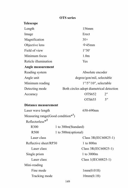
149
OTS series Telescope Length 156mm Image Erect Magnification 30× Objective lens Φ45mm Field of view 1°30′ Minimum focus 1.0m Reticle illumination Yes Angle measurement Reading system Absolute encoder Angle unit degree/gon/mil, selectable Minimum reading 1″/5″/10″, selectable Detecting mode Both circles adopt diametrical detection Accuracy OTS652 2″ OTS655 5″ Distance measurement Laser wave length 650-690nm Measuring range(Good condition*1) Reflectorless*2
R300 1 to 300m(Standard) R500 1 to 500m(optional) Laser class Class 3R(IEC60825-1)
Reflective sheet/RP30 1 to 800m Laser class Class 3R(IEC60825-1)
Single prism 1 to 3000m Laser class Class 1(IEC60825-1) Mini-reading Fine mode 1mm(0.01ft) Tracking mode 10mm(0.1ft)
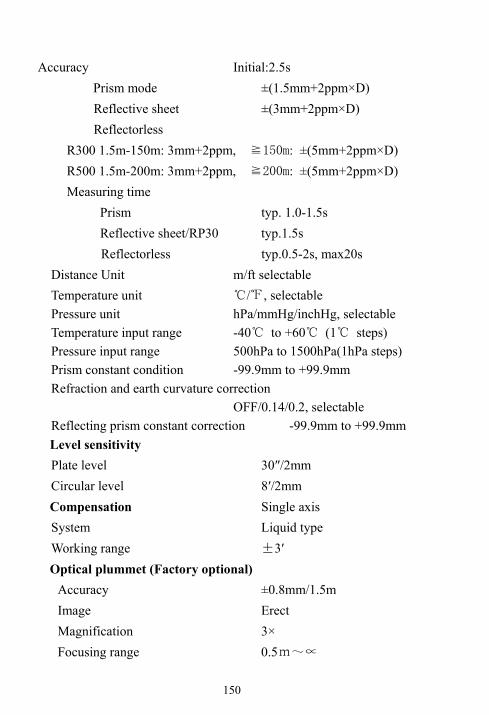
150
Accuracy Initial:2.5s Prism mode ±(1.5mm+2ppm×D)
Reflective sheet ±(3mm+2ppm×D) Reflectorless R300 1.5m-150m: 3mm+2ppm, ≧150m: ±(5mm+2ppm×D) R500 1.5m-200m: 3mm+2ppm, ≧200m: ±(5mm+2ppm×D) Measuring time Prism typ. 1.0-1.5s Reflective sheet/RP30 typ.1.5s Reflectorless typ.0.5-2s, max20s
Distance Unit m/ft selectable Temperature unit ℃/℉, selectable Pressure unit hPa/mmHg/inchHg, selectable Temperature input range -40℃ to +60℃ (1℃ steps) Pressure input range 500hPa to 1500hPa(1hPa steps) Prism constant condition -99.9mm to +99.9mm Refraction and earth curvature correction
OFF/0.14/0.2, selectable Reflecting prism constant correction -99.9mm to +99.9mm Level sensitivity Plate level 30″/2mm Circular level 8′/2mm Compensation Single axis System Liquid type Working range ±3′ Optical plummet (Factory optional)
Accuracy ±0.8mm/1.5m Image Erect Magnification 3× Focusing range 0.5m~∝

151
Field of view 4° Laser plummet*3
Accuracy ±1mm/1.5m Laser class Class 2(IEC60825-1) Laser wave length 635nm
Display Display unit LCD or OLED(Optional)
4 lines ×16 characters Memory Internal memory 128M
Data communication I/O USB&RS-232C(Standard) SD card&Bluetooth (Optional)
Power Battery 3400mAh Li-ion Rechargeable
Voltage 7.4V DC Continuous operation time Approx. 12 hours Chargers FDJ6-Li (100V to 240V 50/60Hz) Charging time (at +20 ) Approx. 4 hours℃ Others:
CPU 32-bit EDM technology Digital signal processing Dimension 175×178×340mm(W×D×H) Weight 5.1kg Water proof IP66(IEC60529) Operating temperature -20℃~+50℃ Storage temperature -40℃~+70℃

152
*1 Good condition: no haze, visibility about 30km *2 Technical Data for OTS series EDM Reflectorless Measurement Range
Range D Range E Range FOption Kodak Gray
Card m m m
White side,
90% reflective
200 250 300
R300
Gray side, 18%
reflective
100 120 150
White side,
90% reflective
300 400 500
R500
Gray side, 18%
reflective
150 200 250
Atmospheric D: Object in strong sunlight, severe heat shimmer
Conditions E: Object in shade, sky overcast
F: Underground, night and twilight
*3 Laser plummet mounted on the bottom of the vertical axis

153
15. Packing list ●Carrying case 1each ●Instrument 1each ●Battery 2 each ●Charger 1 each ●Tool kit 1each ●Instruction manual 1each ●Disc 1 each ●Communication cable(D30-2200) 1 each ●Reflective sheet (only for OTS series) 2 each

154
Attachment 1: atmospheric correction formula and chart (for your reference) Factory setting: temperature: 20 , pressure:1013hPa, 0ppm℃ The correction: Kpt=274.417-0.2904*p/(1+0.0036*t)………………..RTS Kpt=278.960-0.2904*p/(1+0.0036*t)………………...OTS Where: p--Pressure value (hPa) t--Temperature value ( )℃ Kpt--Atmospheric correction (ppm) Example: t=20 , p=1013hpa, L0=1000m.℃ Then: Kpt=0ppm (RTS) Kpt=4ppm (OTS) L=L0(1+Kpt)=1000×(1+0×10-6)=1000.000m (RTS) L=L0(1+Kpt)=1000×(1+4×10⁻⁶)=1000.004m (OTS) The atmospheric value is obtained easily with the atmospheric correction chart. Find the measured temperature in horizontal axis, and pressure in vertical axis on the chart. Read the value from the diagonal line, which is the required atmospheric correction value.

155
For RTS series

156
For OTS series

157
Attachment 2 Correction for refraction and earth curvature Horizontal distance and vertical distance calculation formula: with correction for refraction and earth curvature taken into account: Horizontal distance: D=AC(α)or BE(β) Vertical distance: Z=BC(α)or EA(β) D=L{cosα-(2θ-γ)sinα} Z=L{sinα+(θ-γ)cosα} θ=L*cosα/2R ......Earth curvature correcting item γ=K*Lcosα/2R ......Atmospheric refraction correcting item K=0.14 or 0.20 ......Coefficient of refraction R=6372km ......Radius of earth α(orβ) ......Altitude angle L ......Slope distance
The conversion formula for horizontal and vertical distance is as follows when correction for refraction and earth curvature is not applied: HD=L COSα VD=L SINα

158
Attached file 3: communication instruction and data format 1) Communication parameters setting
BAUD RATE (Baud rate): 2400/4800/9600/19200/38400
PARITY (Parity mode)NONE/ODD/EVEN
DATA BITS (Data length): 7/8
STOP BITS (Stop bit): 0/1/2
PROTOCOL(Protocol): XON/XOFF, NONE
2) Data format
Uploading coordinate data format
│C1│C2│C3│…│Cn│CR│LF│
C1-Cn:
PT#,X,Y,Z,PCODE
NOTE: there is no blank after comma
Example:
101,994.815,1000,987,100.113,STN
CR(ODH) and LF(OAH) at the ending of data block, means the ending
mark of data block
Downloading data format:
CONTROL WORD field1......fieldn
CONTROL WORD, with blank to finish
field1 to fieldn-1 with comma to finish fieldn with CR(ODH) and LF(OAH) to finish
Control code and attached information:

159
JOB Job name, description
NAME Surveyor name
INST Description of instrument model
UNITS meter/feet, degree/gon
SCALE Grid factor, scale factor, elevation
ATMOS Temperature, pressure
STN PT#, instrument height, PCODE
XYZ X (N coordinate), Y(E coordinate), Z(elevation)
BKB PT#, azimuth of backsight point, angle of backsight point
BS PT#[. target height]
FS PT# target height, PCODE[ , serial code]
SS PT# target height, PCODE[ , serial code]
CTL control code[, point code 2[ , serial code2](Select one optionally)
HV HA (Horizontal angle), VA( vertical angle)
SD HA (Horizontal angle), VA(Vertical angle), SD(Slope distance)
HD HA (Horizontal angle), HD(Horizontal distance), VD(height
difference)
OFFSET Radial offset, tangent offset, vertical offset
PTL_OFF offset on the reference line direction, offset on the line
which is cross at right angles with reference line NOTE Note content

160
NOTE: These designs, figures and specifications are subject to change without notice. We shall not be held liable for damages resulting from errors in this instruction manual.

161
Suzhou FOIF Co., Ltd. TEL: +86-512-65224904 FAX: +86-512-65230619 http:// www.foif.com.cn E-mail: [email protected]
2012.05