sustainable energy mod.1: fuel cells & distributed ... vi... · a.a. 2011-2012 sustainable...
TRANSCRIPT
A.A. 2011-2012
Sustainable Energy
Mod.1: Fuel Cells & Distributed
Generation Systems
Thermochemical Power Group (TPG) - DiMSET – University of Genoa, Italy
Dr. Ing. Mario L. Ferrari

A.A. 2011-2012
Lesson VI
Lesson VI: fuel cells (SOFC)

A.A. 2011-2012
Main Characteristics
�Operate at 600-1000°C
�Electrolyte: a solid, non-porous metal oxide (Y2O3-stablilized ZrO2)
�Anode (typically) is a Ni-ZrO2 cermet and the cathode is Sr-doped
LaMnO3
�No liquid electrolyte
�Material problems related to high temperatures
�Highest efficiencies
�Minimal air pollutant emissions and low greenhouse gas emissions
�Wide range of fuels, including various hydrocarbon fuels
�Available for: internal reforming, and high quality by-product heat for
cogeneration or for use in a bottoming cycle
�Technology:
�Up to 2005: 900-1000°C (high efficiency, but high costs)
�From 2005: 700-850°C (planar cells for cost decrease)
�Applications: stationary power generator, (studies for large vehicles)
Lesson VI
A.A. 2011-2012
Electrolyte (1/2)
�Material: SOFCs use solid oxide ceramics, typically perovskites
�Nernst: realized in the 1890s certain perovskites, stabilized zirconias
�Baur and Preis demonstrated in 1943 that such electrolytes could be
used as (oxygen) ion conductors in fuel cells
�Currently, yttrium stablilized zirconia (3, 8, or 10 percent yttria,
abbreviated to YSZ) is the most commonly used electrolyte for SOFC
�Colloidal fabrication and co-sintering processes have emerged, whereby
YSZ membranes are produced as thin films (~10 µm) on porous electrode
structures (reduced operating temperatures)
�Alternative electrolytes (not ready for thermal expansion problems):
�Scandium-doped zirconia (SDZ) is more conductive than YSZ
�Gadolinium-doped ceria is even more conductive, but is partially
reduced in hydrogen at temperatures above 600°C
�Lanthanum gallate with strontium doping on the A-site of the
perovskite and magnesium on the B-site could be used at temperatures
as low as 600°C
Lesson VI

A.A. 2011-2012
Electrolyte (2/2)
Lesson VI

A.A. 2011-2012
Anode
Lesson VI
�Most developers today use a cermet of nickel and YSZ
�Despite the relative success of the Ni-YSZ anode, it has drawbacks
(typically be mitigated by appropriate system design ):
�Sensitivity to sulfur and other contaminants
�Oxidation reduction intolerance
�mechanical and dimensional stability problems, especially during
thermal cycling
�Poor activity for direct oxidation of hydrocarbons
�Researchers at PNNL have demonstrated sulfur tolerance up to 100 ppm
and excellent oxidation/reduction stability

A.A. 2011-2012
Cathode
Lesson VI
�Most cathode materials used in SOFC today are lanthanum-based
perovskite materials (noble materials are no longer used)
�In high temperature SOFC (operating temperature ~1000°C), strontium-
doped LaMnO3 (LSM) is used
�The choice of these materials depend:
�Chemical stability
�Adequate electronic and ionic conductivity
�Relatively high activity
�Manageable interactions with ceramic interconnects
�Thermal expansion coefficients that closely match those of YSZ
�For intermediate-temperature operation (700 to 800°C), a composite layer
(typically 20 to 40 µm thick) of YSZ and LSM is often used
�Chromium vapors can lead to serious poisoning of the cathode
A.A. 2011-2012
Interconnect Materials
Lesson VI
�Interconnect materials for SOFC fall into two categories:
�Conductive ceramic (perovskite) materials for operation at high
temperature (900 to 1000°C)
�Metallic alloys for lower temperature operation
�The ceramic interconnects are primarily doped lanthanum and yttrium
chromites (dopants typically include Mg, Sr, Ca, Ca/Co). They are rigid and
weak (as SOFC)
�Lower operating temperatures would allow the use of ferritic steels, that
could reduce the materials cost, and ferritic steels are typically easier to
process with low-cost processing techniques (corrosion problems).
�Many developers use interconnect coatings of strontium-doped lanthanum
cobaltite or manganite

A.A. 2011-2012
Cell Design
Lesson VI
�Two types of cell designs are being pursued for SOFC :
�Tubular cells
�Planar cells
�The interest in tubular cells is unique for SOFC

A.A. 2011-2012
Tubular SOFC (1/9)
Lesson VI

A.A. 2011-2012
Tubular SOFC (2/9)
Lesson VI
�Type (a) Siemens Westinghouse technology: current is conducted
tangentially around the tube, each tube contains one cell, Tubes are
connected either in series or in parallel.
�Type (b) Acumentrics: current is conducted axially along the tube,
metallic current collector (typically silver) is applied, 2 kW stacks have been
developed
�Type (c) Mitsubishi Heavy Industries: the tube active cell area is
segmented and connected in series, the voltage per tube is higher, and hence
the total current lower, requiring less heavy-duty interconnections between
tubes
�Rolls-Royce Fuel Cell Systems (RRFCS) is developing a cell version with
flattened tubes
A.A. 2011-2012
Tubular SOFC (3/9)
Lesson VI
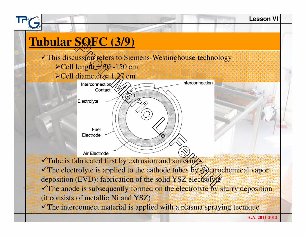
�This discussion refers to Siemens-Westinghouse technology
�Cell length = 30 -150 cm
�Cell diameter = 1.27 cm
�Tube is fabricated first by extrusion and sintering
�The electrolyte is applied to the cathode tubes by electrochemical vapor
deposition (EVD): fabrication of the solid YSZ electrolyte
�The anode is subsequently formed on the electrolyte by slurry deposition
(it consists of metallic Ni and YSZ)
�The interconnect material is applied with a plasma spraying tecnique

A.A. 2011-2012
Tubular SOFC (4/9)
Lesson VI

A.A. 2011-2012
Tubular SOFC (5/9)
Lesson VI

A.A. 2011-2012
Tubular SOFC (6/9)
Lesson VI
�The oxidant is introduced via a central A12O3 injector tube and fuel gas is
supplied to the exterior of the closed-end cathode tube.
�The fuel flows past the anode on the exterior of the cell and in a parallel
direction (co-flow) to the oxidant gas.
�The spent gases are exhausted into a common plenum, where any
remaining fuel reacts.
�For the current YSZ electrolyte to provide sufficient oxygen conductivity,
it must be heated to a high temperature (900 to 1,000°C). This means that
expensive, high temperature alloys must be used to house the fuel cell,
increasing its cost substantially. These costs could be reduced if the
operating temperature was lowered to between 600 to 800°C, allowing the
use of less expensive structural materials such as stainless steel. A lower
operating temperature would also ensure a greater overall system efficiency
and a reduction in the thermal stress in the ceramic structure leading to a
longer service life for the fuel cell.

A.A. 2011-2012
Overall reaction:
Cathode:Anode:
Tubular SOFC (7/9)
Lesson VI
�Performance
Nernst voltage:
The thermodynamic efficiency of SOFCs operating on H2 and O2 at open circuit
voltage is lower than that of MCFCs and PAFCs because of the lower free energy
at higher temperatures. On the other hand, the higher operating temperature of
SOFCs is beneficial in reducing polarization resistance.
Other fuel are possible (CO,CH4)
The voltage ohmic losses in SOFCs: 45 percent from the cathode, 18 percent
from the anode, 12 percent from the electrolyte, and 25 percent from the
interconnect

A.A. 2011-2012
Tubular SOFC (8/9)
Lesson VI
�Performance comparison between Siemens Westinghouse tu bular cell and
Siemens Westinghouse new flattened tube cell

A.A. 2011-2012
Tubular SOFC (9/9)
Lesson VI
�Empirical equations for changes (1->2) in pressure, temperature and….

A.A. 2011-2012
Planar SOFC (1/8)
Lesson VI
�Structural support for membrane/electrolyte assembly:
�Electrolyte-supported. Early planar cells. Thick electrolyte (typically
around 200 µm) which leads to high resistance, requiring high
temperature operation. Sulzer Hexis and Mitsubishi Heavy Industries
are involved in this cell type. Power densities: 140 -220 mW/cm2.
�Cathode-supported. This allows for a thinner electrolyte than
electrolyte-supported cells, but mass transport limitations and
manufacturing challenges make this approach inferior to anode-
supported thin-electrolyte cells.
�Anode-Supported. Advances in manufacturing techniques have
allowed the production of anode-supported cells (supporting anode of
0.5 to 1 mm thick) with thin electrolytes. High power densities in
laboratories: 600 to 800 mW/cm2.
�Metal interconnect-supported. Lawrence Berkeley National
Laboratory, Argonne National Laboratory, and Ceres have pioneered
metal supported cells to minimize mass transfer resistance and the use
of (expensive) ceramic materials. Problems to find apt materials.

A.A. 2011-2012
Planar SOFC (2/8)
Lesson VI
�Interconnect material:
�Ceramic (lanthanum or yttrium chromite) suitable for high
temperature operation (900 to 1000°C). These materials, while
chemically stable are mechanically weak and costly.
�Cr-based or Ni-based superalloy for intermediate-high temperature
operation (800 to 900°C). These materials are chemically stable at
900°C, but they require additional coatings to prevent Cr-poisoning of
the electrodes. In addition, they are expensive and difficult to form.
�Ferritic steel (coated or uncoated) for intermediate temperature
operation (650 to 800°C). While uncoated steels are chemically
unstable, especially during thermal cycling, coated steels provide
corrosion resistance as well as acceptable conductivity when new.
However, thermal cycling performance still requires improvement.

A.A. 2011-2012
Planar SOFC (3/8)
Lesson VI
�Shape of the cell:
�Rectangular, with gases flowing in co-flow, counter-flow, or cross-
flow.
�Circular, typically with gases flowing out from the center in co flow,
and mixing and burning at the edge of the cells. Spiral flow
arrangements and counter flow arrangements have also been proposed.
�Method for creating flow-channels:
�Flat ceramic cell with channels in interconnect or flow-plate.
�Corrugated ceramic with flat interconnects.
�Manifolding arrangement:
�External manifolding.
�Internal manifolding, through the electrolyte.
�Internal manifolding through the interconnect, but not through the
electrolyte.

A.A. 2011-2012
Planar SOFC (4/8)
Lesson VI
�Overview of Types of Planar SOFC: (a) Planar Anode Supported SOFC
with Metal Interconnects; (b) Electrolyte-Supported Planar SOFC
Technology with Metal Interconnect; (c) Electrolyte-Supported Design with
“egg-crate” electrolyte shape and ceramic interconnect.

A.A. 2011-2012
Lesson VI
�The planar anode-supported SOFC with metal interconnects has benefited
from support for fundamental science and stack development under DOE’s
SECA Program. Development of a 1.8 W/cm2 cell under idealized
laboratory conditions, and stacks that can achieve initial power densities of
300 to 500 mW/cm2.
�Sulzer Hexis built 110 1 kW demonstration units based on its electrolyte-
supported technology with superalloy interconnects. The latest version of the
units, integrated into a hot water/heating appliance, has shown a degradation
rate of around 1 to 2 percent per 1000 hrs in continuous operation, and about
2x higher with thermal cycling.
�Mitsubishi tested a 15 kW system with its all-ceramic MOLB design for
almost 10,000 hours with degradation rates below 0.5 percent per 1,000 hrs,
but without thermal cycles, and with power densities ranging from 190 to
220 mW/cm2. Because the interconnect is flat and relatively thin, less of the
expensive LaCrO3 is required than if the flow-passages were in the
interconnect.
Planar SOFC (5/8)

A.A. 2011-2012
Lesson VI
�Benefits of anode-supported cells:
Planar SOFC (6/8)
�Negative aspects reducing cell temperatures (anode-supported cells):
�No interconnect materials for intermediate temperatures.
�Sulfur resistance decreases with temperature.

A.A. 2011-2012
Lesson VI
�Representative State-of-the-Art Button Cell Performance of Anode-
Supported SOFC:
Planar SOFC (7/8)
�Single Cell Performance of LaSrGaMgO Electrolyte (50 µm thick):

A.A. 2011-2012
Lesson VI
�State-of-the-Art of planar Anode-Supported SOFC:
Planar SOFC (8/8)

A.A. 2011-2012
Lesson VI
�Tubular SOFC systems have been scaled-up and integrated into systems
with capacities up to 250 kW. This is accomplished by combining individual
tubes into 3x8 tube modules with capacities of around 2 kW. These modules,
in turn, are combined to form the stack.
Stack Scale-Up (1/2)
Siemens Westinghouse 250 kW Tubular SOFC Installation

A.A. 2011-2012
Lesson VI
�An alternative approach would be to build integrated stack units out of
planar cells.
Stack Scale-Up (2/2)
Example of Window-Pane-Style Stack Scale-Up of Planar Anode-
Supported SOFC to 250 kW