sustainable energy mod.1: fuel cells & distributed ... xix... · a.a. 2011-2012 sustainable...
TRANSCRIPT

A.A. 2011-2012
Sustainable Energy
Mod.1: Fuel Cells & Distributed
Generation Systems
Thermochemical Power Group (TPG) - DiMSET – University of Genoa, Italy
Dr. Ing. Mario L. Ferrari

A.A. 2011-2012
Lesson XIX
Lesson XIX: Stirling Engines

A.A. 2011-2012
Generality of Stirling Engines (1/2)
Lesson XIX
�Alternative machine
�Closed cycle
�External combustion (high flexibility for fuel)
�The general cycle consists of compressing cold gas, heating the gas,
expanding the hot gas, and finally cooling the gas before repeating the cycle
�The Stirling engine is noted for its high efficiency (~40%) compared to
other small size engines, quiet operation, and the ease with which it can use
almost any heat source
�The first Stirling engine example was developed in 1816 by Robert
Stirling
�It is based on a regenerator: an internal heat exchanger and temporary heat
store placed between the hot and cold spaces
�The working fluid passes through it first in one direction then the other
�A typical design is a stack of fine metal wire meshes, with low porosity to
reduce dead space, and with the wire axes perpendicular to the gas flow to
reduce conduction in that direction and to maximize convective heat transfer
�However the recuperator is expensive at not reliable at high temperature
A.A. 2011-2012
Generality of Stirling Engines (2/2)
Lesson XIX
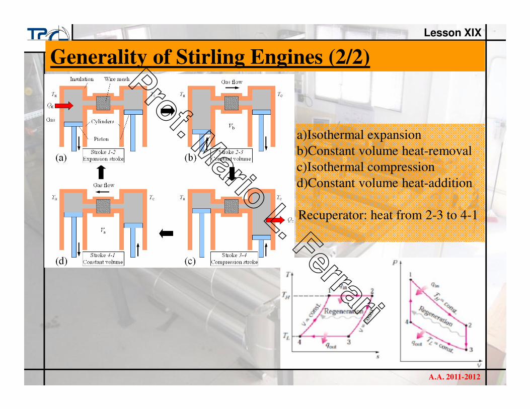
a)Isothermal expansion
b)Constant volume heat-removal
c)Isothermal compression
d)Constant volume heat-addition
Recuperator: heat from 2-3 to 4-1

A.A. 2011-2012
Stirling Ideal Cycle
Lesson XIX
ηηηη=1-Q2/Q1=1-Q1-2/Q3-4
Q1-2=W1-2=-R*TC*ln(v2/v1)
Q3-4=W3-4=R*TH*ln(v4/v3)
-ln(v2/v1) = ln(v4/v3)
ηηηη=1-(-R*TC*ln(v2/v1))/(R*TH*ln(v4/v3))
ηηηη=1-TC/TH
�The efficiency of a Stirling ideal cycle is equal to the Carnot cycle
efficiency working between the same extreme temperatures (TH and TC)
�So, it works at the highest efficiency value (just the ideal cycle)
�Since it is the ideal cycle that is closer to the real cycle, real cycle
efficiency is not equal to Carnot efficiency, but is very high (~40% in few
kW units)

A.A. 2011-2012
Stirling Real Cycle
Lesson XIX

A.A. 2011-2012
Stirling Classification
Lesson XIX
�Type α: it is based on two working pistons (as in the generality slide). This
configuration has an high specific power, but shows problems for gaskets
related to the high temperature cylinder (800°C).
�Type β: it is based on one working piston and on a piston displacer used
for transferring the gas from the zones (hot and cold) through the
recuperator. No high temperature gaskets because the flow insulations are
only in the cold cylinder.
�Type γ: it is similar to β configuration, but it is more simple for
construction because the working piston is located inside a cylinder
separated from the cylinder with piston displacer.
A.A. 2011-2012
Stirling: Type αααα
Lesson XIX
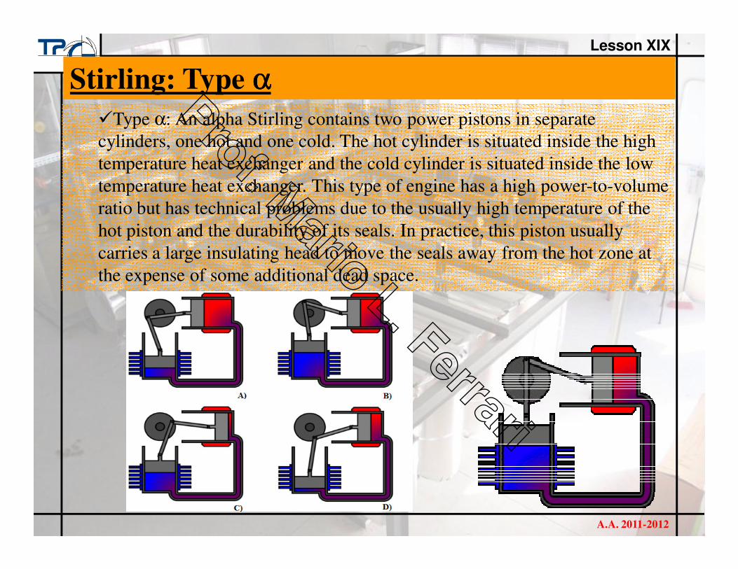
�Type α: An alpha Stirling contains two power pistons in separate
cylinders, one hot and one cold. The hot cylinder is situated inside the high
temperature heat exchanger and the cold cylinder is situated inside the low
temperature heat exchanger. This type of engine has a high power-to-volume
ratio but has technical problems due to the usually high temperature of the
hot piston and the durability of its seals. In practice, this piston usually
carries a large insulating head to move the seals away from the hot zone at
the expense of some additional dead space.

A.A. 2011-2012
Stirling: Type β (β (β (β (Type γγγγ Is Similar))))
Lesson XIX
�Type β: A beta Stirling has a single power piston arranged within the same
cylinder on the same shaft as a displacer piston. The displacer piston is a
loose fit and does not extract any power from the expanding gas but only
serves to shuttle the working gas from the hot heat exchanger to the cold
heat exchanger. When the working gas is pushed to the hot end of the
cylinder it expands and pushes the power piston. When it is pushed to the
cold end of the cylinder it contracts and the momentum of the machine,
usually enhanced by a flywheel, pushes the power piston the other way to
compress the gas. Unlike the alpha type, the beta type avoids the technical
problems of hot moving seals.

A.A. 2011-2012
Stirling: Other Types
Lesson XIX
�Rotary Stirling engine: it seeks to convert power from the Stirling cycle
directly into torque, similar to the rotary combustion engine. No practical
engine has yet been built but a number of concepts, models and patents have
been produced
�Another alternative is the Fluidyne engine (Fluidyne heat pump), which
use hydraulic pistons to implement the Stirling cycle. The work produced by
a Fliudyne engine goes into pumping the liquid. In its simplest form, the
engine contains a working gas, a liquid and two non-return valves.
A.A. 2011-2012
Stirling Engines Compared to ICEs (1/2)
Lesson XIX
Stirling advantages:
�Stirling engine efficiency is higher.
�Stirling engines can run directly on any available heat source (combustion,
solar, geothermal, biological, nuclear sources or waste heat).
�A continuous combustion process can be used to supply heat (less
emission in comparison with intermittent combustion).
�Most types of Stirling engines have the bearing and seals on the cool side
of the engine (they require less lubricant).
�The engine mechanisms are in some ways simpler than other reciprocating
engine types (no valves are needed).
�A Stirling engine uses a single-phase working fluid which maintains an
internal pressure close to the design pressure (low risk of explosion).
�In some cases, low operating pressure allows the use of light cylinders.
�They can be built to run quietly and without an air supply, for use in
submarines or in space applications.
�They start easily and run more efficiently in cold weather.
�They are extremely flexible. They can be used as CHP.
�Waste heat is easily harvested.

A.A. 2011-2012
Stirling Engines Compared to ICEs (2/2)
Lesson XIX
Stirling disadvantages:
�Stirling engine designs require expensive heat exchangers.
�The metallurgical requirements are very demanding and costing.
�Dissipation of waste heat is especially complicated because the coolant
temperature is kept as low as possible to maximize thermal efficiency.
�Stirling engines, especially those that run on small temperature
differentials, are quite large for the amount of power that they produce .
�A Stirling engine cannot start instantly; it literally needs to "warm-up".
�Power output of a Stirling tends to be constant and to adjust it can
sometimes require careful design and additional mechanisms.
�The used gas should have a low heat capacity, so that a given amount of
transferred heat leads to a large increase in pressure.
�Hydrogen may be the best fluid but it is absorbed by metal and better seals
are necessary (safety issues).
�Most technically advanced Stirling engines, like those developed for
United States government labs, use helium as the working gas.
�Some engines use air or nitrogen as the working fluid (lower power
density, but cheap fluids).

A.A. 2011-2012
Stirling Engine by STM Power Inc. (1/2)
Lesson XIX
�Electrical power: 55 kW
�Generator set for combined heat and power applications.
�The total enclosure length is about 2.5 metres, and this assembly has a
mass of about 1300 kg.
�Based on an external combustion chamber and a heat exchanger.
�Number of cylinders: 4
�Generator: 55 kW induction motor (used also for start-up).
�Working fluid: hydrogen (replenished by an electrolyzer)
�Small blower to force combustion air into the burner assembly.
�The blue hoses circulate cooling water through the cool-side.
�The Stirling is designed for auxiliary power and heat production at large
farms, or for plants that produce waste flammable oils.
�This engine can also be adapted to run on low-heat-value landfill gas or
biofuel digester gas.

A.A. 2011-2012
Stirling Engine by STM Power Inc. (2/2)
Lesson XIX
A.A. 2011-2012
Stirling Engine by Genoastirling (1/2)
Lesson XIX
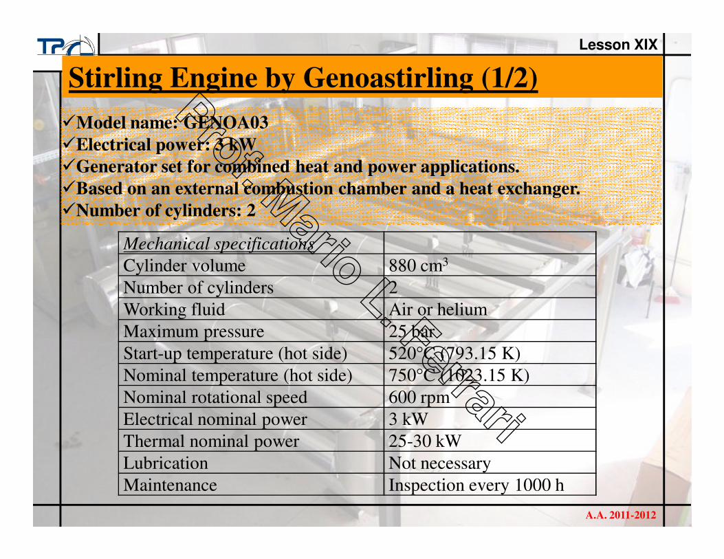
�Model name: GENOA03
�Electrical power: 3 kW
�Generator set for combined heat and power applications.
�Based on an external combustion chamber and a heat exchanger.
�Number of cylinders: 2
Mechanical specifications
Cylinder volume 880 cm3
Number of cylinders 2
Working fluid Air or helium
Maximum pressure 25 bar
Start-up temperature (hot side) 520°C (793.15 K)
Nominal temperature (hot side) 750°C (1023.15 K)
Nominal rotational speed 600 rpm
Electrical nominal power 3 kW
Thermal nominal power 25-30 kW
Lubrication Not necessary
Maintenance Inspection every 1000 h

A.A. 2011-2012
Stirling Engine by Genoastirling (2/2)
Lesson XIX