surgical technique & product cataloguesynthes.vo.llnwd.net/o16/llnwmb8/int mobile/synthes...
TRANSCRIPT

Surgical Technique &
Product CatalogueGuide for Open &
MIS Procedures

I N T R O D U C T I O N
The VIPER® Cortical Fix Fenestrated Screw System is the first pedicle screw
implant to offer enhanced fixation in both the pedicle and vertebral body.
The Cortical Fix thread form doubles the number of screw/bone contact points
thereby increasing the resistance to pull out in the pedicle. With the additional
option to inject cement through the screw shank and into the vertebral body,
this implant is key for patients with diminished bone quality in which screw
purchase is a concern.
This Surgical Technique describes Open and MIS procedures and instruments
that are specific to the VIPER Cortical Fix Fenestrated Screw System with the
CONFIDENCE SPINAL CEMENT SYSTEM® or the V-Max® Mixing and Delivery
System and the VERTEBROPLASTIC® Radiopaque Resinous Material. When
using the Cortical Fix Fenestrated Screw System, it is important to refer to the
appropriate EXPEDIUM® Spine System or VIPER® MIS Spine System Surgical
Technique Guides for comprehensive surgical procedure and system information.
For cement augmentation refer to the package inserts and the surgical technique
manual for CONFIDENCE SPINAL CEMENT SYSTEM or the V-Max Mixing and
Delivery System and the VERTEBROPLASTIC Radiopaque Resinous Material.
SURGICAL TECHNIQUE
• Screw Design 2
• Components for Open Procedures 3
• Components for MIS Procedures 3
• Open Procedure 5
• MIS Procedure 6
PRODUCT CATALOGUE
• VIPER Cort ica l F ix Fenestrated Polyaxia l Screws 13
• Instruments Specif ic to Open Procedures 16
• Instruments Specif ic to MIS Procedures 16
• Instruments Common to Open and MIS Procedures 16
• Trays and Caddies 16
C O N T E N T S
2 3
S U R G I C A L T E C H N I Q U E G U I D E
VIPER tip
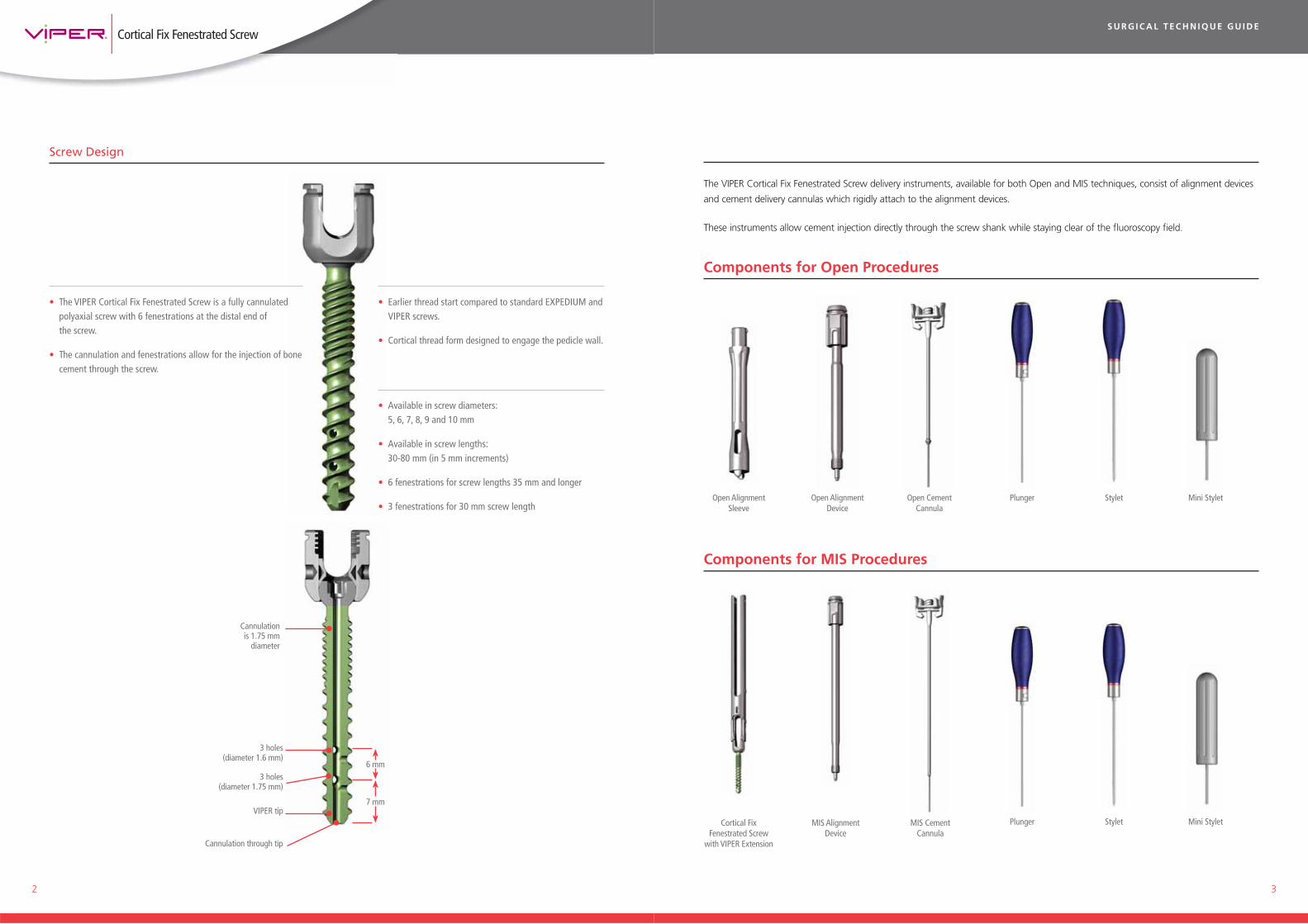
Components for MIS Procedures
• The VIPER Cortical Fix Fenestrated Screw is a fully cannulated polyaxial screw with 6 fenestrations at the distal end of the screw.
• The cannulation and fenestrations allow for the injection of bone cement through the screw.
• Available in screw diameters: 5, 6, 7, 8, 9 and 10 mm
• Available in screw lengths: 30-80 mm (in 5 mm increments)
• 6 fenestrations for screw lengths 35 mm and longer
• 3 fenestrations for 30 mm screw length
• Earlier thread start compared to standard EXPEDIUM and VIPER screws.
• Cortical thread form designed to engage the pedicle wall.
Cannulation is 1.75 mm
diameter
3 holes (diameter 1.6 mm)
7 mm
6 mm
Cannulation through tip
3 holes (diameter 1.75 mm)
Cortical Fix Fenestrated Screw
with VIPER Extension
MIS AlignmentDevice
MIS CementCannula
Screw Design
Open CementCannula
Open AlignmentDevice
Open AlignmentSleeve
The VIPER Cortical Fix Fenestrated Screw delivery instruments, available for both Open and MIS techniques, consist of alignment devices
and cement delivery cannulas which rigidly attach to the alignment devices.
These instruments allow cement injection directly through the screw shank while staying clear of the fluoroscopy field.
StyletPlunger Mini Stylet
StyletPlunger Mini Stylet
Components for Open Procedures

4 5
S U R G I C A L T E C H N I Q U E G U I D E
STEP 1: PREPARE THE SPINE
• Refer to the EXPEDIUM or VIPER Surgical Techniques for pedicle targeting and preparation.
• Pedicle preparation is performed using a selection of awls, pedicle probes, drill bits, ball tip feelers and bone taps.
NOTE: If a biopsy is completed prior to screw placement, care should be taken not to place the tip of the biopsy needle beyond the desired location of the screw tip in order to reduce the risk for cement leakage or extravasations.
STEP 2: INSERTION OF SCREWS
• The Screws are inserted for Open or MIS procedures using the same technique as the EXPEDIUM or VIPER polyaxial screws respectively.
Please refer to the EXPEDIUM or VIPER System Surgical Techniques.
• For MIS screw insertion, do not remove the VIPER screw extension after screw insertion. The extension must remain in place throughout cement delivery.
NOTE: Fenestrated screws should NOT be placed bicortically. It is very important not to breach the pedicle wall or anterior cortex of the vertebral body to avoid cement extrusion into retroperitoneal space. Use appropriate imaging techniques, such as fluoroscopy, to confirm screw placement. NOTE: The alignment device MUST be used for each screw intended
for cement augmentation. Without the alignment device, there is a potential risk of cannula breakage. Use of the alignment device will prevent undue stress from being applied to the cannula.
Open Alignment Device
Open Alignment Sleeve
Step 3: Open Procedure (Proceed to Page 6 for MIS Procedure)
STEP 3a: ASSEMBLY OF THE OPEN ALIGNMENT GUIDE
• Check that the alignment device and alignment sleeve are clear of any cement from prior use.
• Insert the alignment device into the alignment sleeve and push the two pieces together until you hear a click.
STEP 3b: ALIGNMENT OF THE SCREW
• Align the tabs of the alignment sleeve with the rod slot in the screw head, ensuring that the soft tissue does not impinge on the connection of the alignment sleeve to the screw head.
• Thread the assembled alignment guide into the screw head. This will align the screw shank to the screw head.
• Confirm that the alignment device is fully seated by checking that the alignment guide and alignment sleeve are in close proximity (See detail).
• Repeat this step for each screw intended for cement augmentation. Proceed to Page 7 for remainder of the technique.

6 7
S U R G I C A L T E C H N I Q U E G U I D E
Cannula for Open procedure
Cannula for MIS procedure
Step 3: MIS Procedure
STEP 3: ALIGNMENT OF SCREW
• Check that the alignment device is clear of any cement from prior use.
• Insert the MIS alignment device into the VIPER extension and thread it into the screw head. This will align the screw shank to the screw head.
• Confirm that the alignment device is fully seated by checking that the alignment device handle and VIPER Screw extension are in close proximity (See detail).
STEP 4a: CEMENT PREPARATION
• Once the Fenestrated Screws are in place and the alignment devices are attached, prepare the cement according to the manufacturer’s published instructions.
STEP 4b: CONNECTION OF CANNULA TO THE CEMENT RESERVOIR
• Thread the CONFIDENCE SPINAL CEMENT SYSTEM reservoir onto the appropriate cannula (Open or MIS).
• When augmenting multiple screws/levels with cement, attention must be paid not to exceed the working time of the cement prior to the completion of cement delivery through the screw. When the cement working time is close to completion, a new cement, cement delivery system package and cannula should be used for any remaining levels/screws.
NOTE: Bone cement should be prepared as per the cement package insert or surgical technique manual. Time/Temperature Graph provided in the package insert or surgical technique manual should be followed carefully.
NOTE: If using the V-Max Mixing and Delivery System and the Vertebroplastic Radiopaque Resinous Material, the CONFIDENCE System Luer Adapter (2839-99-001) is screwed onto the cannula before attaching those systems to the cannula.
NOTE: The alignment device MUST be used for each screw intended for cement augmentation. Without the alignment device, there is a potential risk of cannula breakage. Use of the alignment device will prevent undue stress from being applied to the cannula.
• Repeat this step for each screw intended for cement augmentation.
NOTE: The remainder of the procedure is identical for Open and MIS Procedures.
8 9
S U R G I C A L T E C H N I Q U E G U I D E
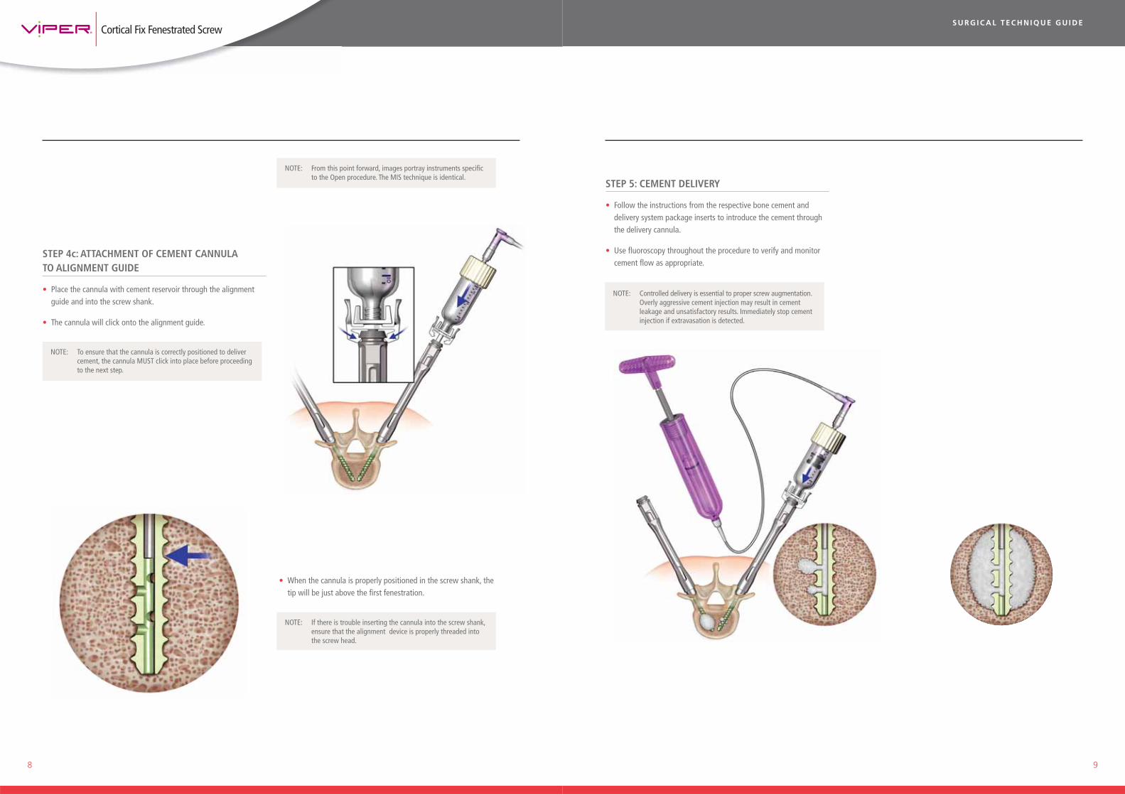
STEP 4c: ATTACHMENT OF CEMENT CANNULA TO ALIGNMENT GUIDE
• Place the cannula with cement reservoir through the alignment guide and into the screw shank.
• The cannula will click onto the alignment guide.
NOTE: If there is trouble inserting the cannula into the screw shank, ensure that the alignment device is properly threaded into the screw head.
NOTE: To ensure that the cannula is correctly positioned to deliver cement, the cannula MUST click into place before proceeding to the next step.
NOTE: From this point forward, images portray instruments specific to the Open procedure. The MIS technique is identical.
• When the cannula is properly positioned in the screw shank, the tip will be just above the first fenestration.
STEP 5: CEMENT DELIVERY
• Follow the instructions from the respective bone cement and delivery system package inserts to introduce the cement through the delivery cannula.
• Use fluoroscopy throughout the procedure to verify and monitor cement flow as appropriate.
NOTE: Controlled delivery is essential to proper screw augmentation. Overly aggressive cement injection may result in cement leakage and unsatisfactory results. Immediately stop cement injection if extravasation is detected.

10 11
S U R G I C A L T E C H N I Q U E G U I D E
STEP 7a: SUBSEQUENT LEVEL AUGMENTATION
• Place the existing cannula and cement reservoir into the next alignment guide as per step 4c and follow the instructions through step 6.
• Repeat for each desired vertebral level, ensuring that cement flow has stopped between each level.
• If an additional cement package is needed, remove the existing cannula and attach a new cannula.
• If additional cement is needed beyond its working time, dispose of the cement and cannula. Use a new cannula and mix a new dose of cement for remaining screws.
STEP 6: REMOVAL OF DELIVERY CANNULA
• When the appropriate amount of cement has been introduced, stop cement introduction as indicated per the respective bone cement technique.
• Disengage the cannula from the alignment guide by depressing the tabs on each side of the cannula and remove it from the screw as soon as cement injection is completed and flow has stopped through the cannula.
NOTE: It is essential to confirm that cement flow has stopped before disengaging the cement delivery system from the screw head.
STEP 7b: SUBSEQUENT LEVEL AUGMENTATION
Optional Step
• The plunger can be used to pass the cement remaining in the cannula into the screw after the cement reservoir has been emptied. Detach the reservoir from the cannula and proceed with plunger insertion.
STEP 8: REMOVAL OF ALIGNMENT DEVICES
• After cement introduction, the alignment devices can be unthreaded from the screw head.
NOTE: The VIPER wrenches can be used for counter torque on the Open Alignment Guides as well.
• Apply counter-torque using the VIPER wrenches on VIPER screw extension while removing alignment devices.

12 13
P R O D U C T C A T A L O G U E
Cleaning Stylet
Mini-Stylet
STEP 9: ROD INSERTION AND LOCKING
• Choose the appropriate length rod with the desired contour. Place the rod into the polyaxial screw heads.
• Capture the rod into the implant by inserting the single innie setscrew.
• The alignment guide can be used to help position the head and reduce the chance of cross-threading.
STEP 10: RESIDUAL CEMENT REMOVAL
• After use, the Alignment Devices should be visually inspected for any cement.
• If cement remains in the alignment device, insert the Stylet through Alignment Device and rotate to ensure any cement is removed.
• Insert the Mini-Stylet into the threaded tip of the Alignment Device.
• If cement remains in the device, repeat cleaning steps above or return it to DePuy Spine.
NOTE: After cement injection, no torsional movement should be applied to the screw throughout the cement setting time outlined in the respective package insert. At the end of the case, any opened cannulas must be discarded.
VIPER Cortical Fix Fenestrated Screws (Polyaxial, Titanium Screws for a 5.5mm Rod)
5mm
1867-27-530 5mm x 30mm
1867-27-535 5mm x 35mm
1867-27-540 5mm x 40mm
1867-27-545 5mm x 45mm
1867-27-550 5mm x 50mm
1867-27-555 5mm x 55mm
1867-27-560 5mm x 60mm
1867-27-565 5mm x 65mm
1867-27-570 5mm x 70mm
1867-27-575 5mm x 75mm
1867-27-580 5mm x 80mm
6mm
1867-27-630 6mm x 30mm
1867-27-635 6mm x 35mm
1867-27-640 6mm x 40mm
1867-27-645 6mm x 45mm
1867-27-650 6mm x 50mm
1867-27-655 6mm x 55mm
1867-27-660 6mm x 60mm
1867-27-665 6mm x 65mm
1867-27-670 6mm x 70mm
1867-27-675 6mm x 75mm
1867-27-680 6mm x 80mm
• Once the cement is set as outlined in the respective package insert, final tighten with the Hexlobe Shaft inserted into the T-Handle Torque Wrench, set to 80 in-lb.
• Insert the shaft through the Counter Torque Device and into the Single Innie. Rotate the T-Handle clockwise until it clicks and resistance is no longer evident.

14 15
P R O D U C T C A T A L O G U E
VIPER Cortical Fix Fenestrated Polyaxial Screws
7mm
1867-27-730 7mm x 30mm
1867-27-735 7mm x 35mm
1867-27-740 7mm x 40mm
1867-27-745 7mm x 45mm
1867-27-750 7mm x 50mm
1867-27-755 7mm x 55mm
1867-27-760 7mm x 60mm
1867-27-765 7mm x 65mm
1867-27-770 7mm x 70mm
1867-27-775 7mm x 75mm
1867-27-780 7mm x 80mm
8mm
1867-27-830 8mm x 30mm
1867-27-835 8mm x 35mm
1867-27-840 8mm x 40mm
1867-27-845 8mm x 45mm
1867-27-850 8mm x 50mm
1867-27-855 8mm x 55mm
1867-27-860 8mm x 60mm
1867-27-865 8mm x 65mm
1867-27-870 8mm x 70mm
1867-27-875 8mm x 75mm
1867-27-880 8mm x 80mm
VIPER Cortical Fix Fenestrated Polyaxial Screws
9mm
1867-27-930 9mm x 30mm
1867-27-935 9mm x 35mm
1867-27-940 9mm x 40mm
1867-27-945 9mm x 45mm
1867-27-950 9mm x 50mm
1867-27-955 9mm x 55mm
1867-27-960 9mm x 60mm
1867-27-965 9mm x 65mm
1867-27-970 9mm x 70mm
1867-27-975 9mm x 75mm
1867-27-980 9mm x 80mm
10mm
1867-27-030 10mm x 30mm
1867-27-035 10mm x 35mm
1867-27-040 10mm x 40mm
1867-27-045 10mm x 45mm
1867-27-050 10mm x 50mm
1867-27-055 10mm x 55mm
1867-27-060 10mm x 60mm
1867-27-065 10mm x 65mm
1867-27-070 10mm x 70mm
1867-27-075 10mm x 75mm
1867-27-080 10mm x 80mm

16
Instruments Specific to Open Procedures
Part Number Part Description
2797-26-401 Open Alignment Device
2797-26-509 Open Alignment Sleeve
2797-26-500 Open Cannula (pre-packed sterile/single use)
Instruments Specific to MIS Procedures
Part Number Part Description
2797-26-400 MIS Alignment Device
2797-26-524 Loading Block
2797-26-508 MIS Cannula (pre-packed sterile/single use)
Instruments Common to Open and MIS Procedures
Part Number Part Description
2797-26-403 Stylet
2797-26-511 Mini Stylet
2797-26-402 Plunger
2867-45-155 VIPER Wrench
Trays and Caddies
Part Number Part Description
2797-26-520 Open Instrument Tray
2797-26-522 MIS Instrument Tray
2797-26-523 Instrument Tray Lid
2797-26-525 Implant Tray
2797-26-526 Implant Tray Lid
2797-26-515 5.0mm Caddy
2797-26-516 6.0mm Caddy
2797-26-517 7.0mm Caddy
2797-26-518 8.0mm Caddy
2797-26-529 9.0 & 10.0mm Cassette
2797-26-521 9.0 & 10.0mm Implant Tray & Lid

INDICATIONS FOR USEThe VIPER® Fenestrated Screw System is intended to be used with the CONFIDENCE SPINAL CEMENT SYSTEM® or the V-MAX® Mixing and Delivery System and the VERTEBROPLASTIC® Radiopaque Resinous Material to provide immobilization and stabilization of spinal segments in the treatment of acute and chronic instabilities or deformities of the thoracic, lumbar and sacral spine in patients with diminished bone quality (e.g., osteoporosis, osteopenia, metastatic disease). It is intended to provide temporary internal support and fixation while fusion mass is consolidating or fracture is healing, or for the palliative reconstruction of the tumor patients.
WARNINGS, PRECAUTIONS & CONTRAINDICATIONSRefer to the VIPER FENESTRATED SCREW SYSTEM IFU for complete information.
Limited Warranty and Disclaimer: DePuy Spine products are sold with a limited warranty to the original purchaser against defects in workmanship and materials. Any other express or implied warranties, including warranties of merchantability or fitness, are hereby disclaimed.
www.depuy.com
©DePuy Spine, Inc. 2011 All rights reserved.
9085-38-000 : Rev 2 12/11
DePuy Spine EMEA is a trading division of DePuy International Limited. Registered Office: St Anthony’s Road, Leeds LS11 8DT, England Registered in England No. 3319712
Manufactured by one of the following:
*For recognized manufacturer, refer to product label.
DePuy Spine, Inc. 325 Paramount DriveRaynham, MA 02767USATel: +1 (800) 227 6633Fax: +1 (800) 446 0234
DePuy International, Ltd.St Anthony’s RoadLeeds LS11 8DTEnglandTel: +44 (0) 113 387 7800Fax: +44 (0) 113 387 7890
DePuy Spine, Inc. 325 Paramount DriveRaynham, MA 02767-0350USA
DePuy Spine SÀRL Chemin Blanc 36CH-2400 Le LocleSwitzerland
Medos International SÀRLChemin Blanc 38CH-2400 Le LocleSwitzerland
Authorised US Representative: Authorised EMEA Representative: