surface plasmon resonance refractive index sensor based on …cofs.szu.edu.cn/papers/2019...
TRANSCRIPT

Surface plasmon resonance refractive indexsensor based on fiber-interface waveguideinscribed by femtosecond laserYUNFANG ZHANG,1,2 CHANGRUI LIAO,1,2,* CHUPAO LIN,1,2 YU SHAO,1,2 YING WANG,1,2 AND
YIPING WANG1,2
1Guangdong and Hong Kong Joint Research Centre for Optical Fibre Sensors, Shenzhen University, Shenzhen 518060, China2Key Laboratory of Optoelectronic Devices and Systems of Ministry of Education and Guangdong Province, College of Physics and OptoelectronicEngineering, Shenzhen University, Shenzhen 518060, China*Corresponding author: [email protected]
Received 18 March 2019; revised 15 April 2019; accepted 15 April 2019; posted 16 April 2019 (Doc. ID 362554); published 8 May 2019
A novel surface plasmon resonance (SPR) configurationbased on fiber-interface waveguide was proposed and real-ized by combining the technology of femtosecond laserwriting waveguide with SPR effect for measuring refractiveindex (RI) of analyte. A U-shaped waveguide is inscribed inthe coreless fiber and its bottom is very close to the fibersurface, which can produce strong evanescent field beingsensitive to ambient media. When the fiber surface is coatedwith a layer of gold film, the strong evanescent field canexcite the SPR effect on the fiber surface. Most importantly,different from some types of fiber SPR sensors with a fragilephysical structure, the fiber-interface waveguide SPR sensorexhibits an excellent mechanical strength. Such a SPR sen-sor exhibits a high sensitivity of ∼3352 nm∕RIU at theRI value of ∼1.395, which may have important practicalapplications in medicine, environmental monitoring, andfood safety. © 2019 Optical Society of America
https://doi.org/10.1364/OL.44.002434
The rapid and sensitive detection of analytes at low concentra-tions is paramount in many fields, such as medicine, environ-mental monitoring, and food safety. Surface plasmon resonancefiber sensor is an appealing solution to this problem because thesensing platform is compact and cost-effective (low cost equip-ment), and it is possible to collect measurements in situ andremotely [1,2]. It is important to note that acquisition ofexcellent mechanical strength, simple fabrication approaches,and high efficiency of exciting the SPR effect have importantpractical implications for fiber sensors.
However, one difficulty of the trade-off between themechanical strength of the fiber and the intensity of evanescentfield to excite SPR effect significantly blocks the practical ap-plications of SPR fiber sensor. The commonly used methods toobtain strong evanescent field includes removing all or part ofthe cladding (via etching, side polishing, or femtosecond lasermicromaching) and tapering the fiber to allow the light to
escape to the cladding [3–6]. Unfortunately, these SPR fibersensors are very fragile due to the destroyed physical structure,thus it becomes one of blocks in the practical implications.
To obtain an optical fiber with complete physical structureand strong evanescent field, Guan et al. fabricated one surface-core fiber and coated graphene on it for polarizer use [7,8]. Thesurface-core fibers make good performance on light guidance,but the structural flexibility is poor. Femtosecond laser directwriting is an effective way for waveguide fabrication in silica[9]. Our team first proposed the fiber-interface waveguide,which is fabricated on the cladding-air interface by femtosec-ond laser direct writing and produces a strong evanescent fieldon the fiber surface [10,11]. Compared with the surface-corefiber, the fiber-interface waveguide is much better in structuralflexibility and easier to connect with single mode fiber (SMF)system.
In this Letter, we propose a fiber interface waveguide SPRsensor for RI measurement, which is combined the opticalfiber sensing with femtosecond laser direct writing waveguideand SPR sensing technology. As is shown in Fig. 1, a U-shapedwaveguide (or named interface waveguide) is inscribed in thecoreless fiber. To obtain a strong evanescent field, thebottom of U-shaped waveguide is very close to the interface
Fig. 1. Schematic diagram of fiber-interface waveguide SPR sensor.
2434 Vol. 44, No. 10 / 15 May 2019 / Optics Letters Letter
0146-9592/19/102434-04 Journal © 2019 Optical Society of America

of fiber cladding and air. The two ends of U-shaped waveguideare, respectively, connected with two cores of single mode fiberfor leading the interface waveguide into optical path. At last, alayer of gold film with 45 nm is evenly coated on the corelessfiber surface. Such a fiber interface-waveguide SPR sensor notonly have a high RI sensitivity of 3352 nm/RIU at an RI valueof 1.395 but also exhibits a strong mechanical strength withno structural damage, which eases the trade-off between themechanical strength of the optical fiber and the evanescent fieldintensity.
The flowchart of device fabrication process is illustratedin Fig. 2.
A section of coreless fiber is spliced with two SMFs(Corning, SMF-28), which supplies a platform for a U-shapedwaveguide fabrication.
A U-shaped waveguide is inscribed in the coreless fiber andconnected with the cores of two SMFs. Two ends of U-shapedwaveguide are stretched into the cores of SMFs with a length of∼15 μm aiming to increase the coupling efficiency. The heightof the interface-waveguide (h) is designed to be 60 μm, thus thebottom part of the U-shaped waveguide is very close to thesurface of the coreless fiber with a strong evanescent field.To decrease the bending loss of the U-shaped waveguide,the radius of the curved parts (R) is optimized to be 50 mm.
A femtosecond laser (PHAROS, 513 nm/290 fs/200 kHz)is employed to fabricate the waveguide and an oil-immersed
objective lens (NA � 1.4) is selected to eliminate the aberra-tion caused by the cylindrical morphology of the fiber. Thefixed fiber is translated relative to the focused laser beam bya 3D air-bearing motion stage (Aerotech). The laser pulseenergy is optimized to be ∼120 nJ, and the translation velocityof the fiber is set to be 0.2 mm/s. The propagation loss of theinterface waveguide at 632 nm is measured to be 1.08 dB/mmby the cutback method.
The surface of the coreless fiber with the interface waveguideis coated with 45 nm-thickness gold film by magnetron sput-tering method. The pressure of the vacuum chamber is evacu-ated to 5 × 10⁻⁴ Pa and then argon fills continuously with aquasi-static pressure of 2 Pa, and the DC current intensityis set to be 40 mA. To obtain a homogeneous gold film,the optical fiber is automatically rotated with a uniform speedduring the film coating. When the above processes are allcompleted, the fiber-interface waveguide SPR configurationis obtained.
The SPR effect can be excited at the interface between thegold film and the dielectric media, when the energy and mo-mentum of the incident light match those of the surface plas-mon waves (SPW). The photon energy being coupled to theelectrons of gold film achieves a resonant dip in the spectrum.The propagation constant of the SPW strongly depends on theRI of surrounding medium. Therefore, the small RI change ofthe medium adjacent to gold film will produce a measurableshift of the resonant dip.
The RI distribution of the laser-inscribed waveguide is firststudied by a 3D reconstruction system for optical fiber refrac-tive index distribution [12]. The cross-sectional RI distributionof the laser-inscribed waveguide is clearly presented in Fig. 3(a),where it consists of both negative and positive RI modulationsegments. As illustrated in Fig. 3(b), the largest magnitude ofthe negative RI modulation is measured to be ∼4.2 × 10⁻², andthe positive RI modulation is up to ∼8 × 10⁻³, which ensuresgood confinement of the guided light.
The gold film coated on the fiber surface is analyzed by scan-ning electron microscope (SEM). As shown in Figs. 4(a) and4(b), the gold film on the fiber surface is found to be smoothand homogeneous. Figure 4(c) is the cross-sectional profile ofthe gold film, and we find the thickness uniformity of the goldfilm is good. All above characteristics supply a pretty resonanceplatform for SPW. To clearly observe the distance between thebottom of U-shaped waveguide and the cladding interface, thedevice is cutoff at the middle place of U-shaped waveguide, andits cross-sectional morphology is collected by the optical micro-scope as shown in Fig. 4(d). The microscope morphology of
Fig. 2. Flowchart of device fabrication. (a) and (b) Section ofcoreless fiber (L1 � 12.9 mm) is spliced between two SMFs.(c) Interface waveguide is inscribed in the coreless fiber.L2 � 5 mm, h � 60 μm, R � 50 mm. (d) Layer of gold film isevenly coated on the coreless fiber surface. d � 45 nm.
Fig. 3. (a) Two dimensional and (b) three dimensional cross-sec-tional RI difference diagrams of the laser-waveguide.
Letter Vol. 44, No. 10 / 15 May 2019 / Optics Letters 2435

laser waveguide is corresponding to its RI modulationdiagrams, the black segment is a negative RI modulation,and the bright segment is a positive RI modulation. The lasermodulated area is ∼14 μm in depth and ∼3 μm in width.Moreover, the bottom of U-shaped waveguide, which is veryclose to the fiber cladding interface, would generate a strongevanescent field at the coreless fiber surface.
The RI response of this SPR sensor is investigated by thespecific RI testing system [3]. The input of the device is con-nected with a Tungsten halogen light source (100 W, LS-3000,Ocean Optics), which supplies a broadband light signal input.The output end is linked to the spectrometer with the operat-ing wavelength range of 300–1100 nm (QE-6500, Ocean spec-tra). To eliminate the interference of other factors, the testedfiber is fixed between two fiber holders to keep the sensing areato be naturally straightened and all the light path is protectedbecause the intensity and polarization of the transmission lightmight be affected by the fiber deformation. In room temper-ature, the SPR sensor is immersed into a series of standard RIliquids (Cargille Labs) with the RI value from 1.305 to 1.395.After each measurement, the sensor is carefully cleaned byalcohol to remove the residual liquid until the spectrum returnsto the initial status.
In Fig. 5(a), the normalized transmission spectra of the sen-sor are obtained from the transmission spectra of the senor indifferent RI liquids divided by the one in air, and the resonantdip is resulting from the light coupling from the fiber-interfacewaveguide mode to the plasmon wave of the gold film. InFig. 5(b), an exponential fitting method has been employedto reveal the RI response of the traced dip. It is found thatas the liquid RI increases the wavelength of the resonant dipexhibits a significant red shift of 144 nm. It is important tonote that a high sensitivity of ∼3353 nm∕RIU can be achieved
at the RI value of ∼1.395. The figure of merit (FOM) of thedevice, which is calculated with the RI sensitivity divided bythe full-width at half-maximum of the resonant dip, is about30 at the RI value of ∼1.395.
To simulate the mode characteristics of the fiber interface-waveguide SPR sensor, we use the finite element method withperfect match layers (PMLs) boundaries [3], and the simulationis carried out by COMSOL Multiphysics [13]. The simulatedmodel is established based on the device size in Fig. 2(d).According to the definition, the wavelength sensitivity isgiven by
Sλ � Δλres∕Δnα, (1)
where λres is the plasmon resonant wavelength of the SPR sen-sor, and nα is the liquid RI. The confinement loss can be cal-culated according to the following equation [3]:
α � 8.386 · k0 Im�neff ��dB∕m�, (2)
where k0 � 2π∕λ is the wavenumber in meter scale [13].The calculated loss spectra of the SPR sensor in different RI
liquids are plotted in Fig. 6(a). It can be seen from this figurethat the peak wavelength shows an obvious red shift when nα isincreased from 1.305 to 1.395 and the peak intensity stops togrow but begins to decrease when the nα increases to 1.385.
Fig. 4. (a) and (b) SEM images of the coreless fiber surface coatedwith gold film. (c) Cross-sectional profile of the gold film. (d) Opticalmicroscope image of the cross-sectional coreless fiber with interfacewaveguide.
Fig. 5. Liquid RI response of the fiber-interface waveguide SPR sen-sor. (a) Transmission spectra of the fiber-interface waveguide SPR im-mersed in different RI liquids. (b) Exponential fitting relationshipbetween the wavelength of the traced resonant dip and the RI of liquid.
2436 Vol. 44, No. 10 / 15 May 2019 / Optics Letters Letter
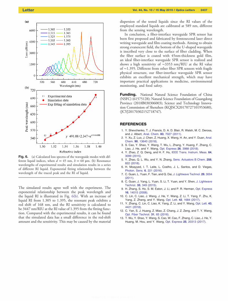
The simulated results agree well with the experiment. Theexponential relationship between the peak wavelength andthe liquid RI is illustrated in Fig. 6(b). With an increase ofliquid RI from 1.305 to 1.395, the resonant peak exhibits ared shift of 168 nm, and the RI sensitivity is calculated tobe 3447 nm/RIU at the RI value of 1.395 from the fitting func-tion. Compared with the experimental results, it can be foundthat the simulated data has a small difference in the red-shiftamount and the sensitivity. This may be caused by the material
dispersion of the tested liquids since the RI values of theemployed standard liquids are calibrated at 589 nm, differentfrom the sensing wavelength.
In conclusion, a fiber-interface waveguide SPR sensor hasbeen first proposed and fabricated by femtosecond laser directwriting waveguide and film coating methods. Aiming to obtainstrong evanescent field, the bottom of the U-shaped waveguideis inscribed very close to the surface of fiber cladding. Whenthe fiber surface is coated with 45nm-thickness gold film,an ideal fiber-interface waveguide SPR sensor is realized andshows a high sensitivity of ∼3353 nm∕RIU at the RI valueof ∼1.395. Different from other fiber SPR sensors with fragilephysical structure, our fiber-interface waveguide SPR sensorexhibits an excellent mechanical strength, which may haveimportant practical applications in medicine, environmentalmonitoring, and food safety.
Funding. National Natural Science Foundation of China(NSFC) (61575128); Natural Science Foundation of GuangdongProvince (2018B030306003); Science and Technology Innova-tion Commission of Shenzhen (KQJSCX20170727101953680),(JCYJ20170302152718747).
REFERENCES
1. Y. Shevchenko, T. J. Francis, D. A. D. Blair, R. Walsh, M. C. Derosa,and J. Albert, Anal. Chem. 83, 7027 (2011).
2. Y. Xu, Z. Luo, J. Chen, Z. Huang, X. Wang, H. An, and Y. Duan, Anal.Chem. 90, 13640 (2018).
3. S. Cao, Y. Shao, Y. Wang, T. Wu, L. Zhang, Y. Huang, F. Zhang, C.Liao, J. He, and Y. Wang, Opt. Express 26, 3988 (2018).
4. Y. Zhao, Z. Q. Deng, and H. F. Hu, IEEE Trans. Instrum. Meas. 64,3099 (2015).
5. Y. Zhao, Q. L. Wu, and Y. N. Zhang, Sens. Actuators B Chem. 258,822 (2018).
6. H. Moayyed, I. T. Leite, L. Coelho, J. L. Santos, and D. Viegas,Photon. Sens. 6, 221 (2016).
7. C. Guan, L. Yuan, F. Tian, and Q. Dai, J. Lightwave Technol. 29, 3004(2011).
8. C. Guan, J. Yang, L. Yuan, S. Li, T. Yuan, and Y. Shen, J. LightwaveTechnol. 33, 349 (2015).
9. H. Zhang, S. Ho, S. M. Eaton, J. Li, and P. R. Herman, Opt. Express16, 14015 (2008).
10. C. Lin, C. Liao, J. Wang, J. He, Y. Wang, Z. Li, T. Yang, F. Zhu, K.Yang, Z. Zhang, and Y. Wang, Opt. Lett. 42, 1684 (2017).
11. Y. Zhang, C. Lin, C. Liao, K. Yang, Z. Li, and Y. Wang, Opt. Lett. 43,4421 (2018).
12. C. Yan, S. J. Huang, Z. Miao, Z. Chang, J. Z. Zeng, and T. Y. Wang,Opt. Fiber Technol. 31, 65 (2016).
13. T. Wu, Y. Shao, Y. Wang, S. Cao, W. Cao, F. Zhang, C. Liao, J. He, Y.Huang, M. Hou, and Y. Wang, Opt. Express 25, 20313 (2017).
Fig. 6. (a) Calculated loss spectra of the waveguide modes with dif-ferent liquid indices, when d � 45 nm, h � 60 μm. (b) Resonancewavelengths of experimental results and simulation results in a seriesof different RI liquid. Exponential fitting relationship between thewavelength of the traced peak and the RI of liquid.
Letter Vol. 44, No. 10 / 15 May 2019 / Optics Letters 2437