surface modification of medical grade titanium alloy by ... · pdf filesurface modification of...
TRANSCRIPT
Surface modification of medical grade titanium alloy by forced pulsed water jet (FPWJ) D Kalliecharan
1, A Tieu 2, B Daniels
2, W Yan 2, M Xu
2, M Vijay 2, T L Monchesky
1 1Dalhousie University, Department of Physics & Atmospheric Science, Canada 2VLN Advanced Technologies Inc., Canada ABSTRACT Medical grade titanium (Ti-6Al-4V Grade23, ASTM F-136) was treated with pulsed water jet (PWJ) blasting for various exposures. We monitored changes in the surface morphology, and transverse velocity (VTR) settings below 120 mm/s were found to erode the Ti α-phase, and Ti β-phase grain boundaries, which gave rise to nanoscale and micron-scale surface features, and produced a residual strain in the Ti β-phase. The ideal VTR setting of 75 mm/s produced a surface roughness Sa = 5 μm that is comparable to typical surface roughness for titanium implants. X-ray photoelectron spectroscopy shows a small increase in TiO2 as well as an increase of V at the surface. 1 INTRODUCTION Surface topography of titanium, more specifically surgical grade titanium (grade 23, Ti-6Al-4V) is an integral component of medical implant applications. The nature of implanting a foreign load-bearing object can have difficulty with osteointegration, such factors include biocompatibility, cell adhesion, increased hardness and wear. Providing an implant that has characteristics that mimic bone can be challenging, and is still much an unexplored territory. The most common surface preparation processes for metallic biomaterials are grit blasting and chemical etching (1). Grit blasting leaves behind embedded Al2O3 particles in the implant that can detach and find their way into the artificial joint and cause wear (2). Furthermore, these grit particles are believed to be responsible for implant loosening (3), which is the leading cause for revision surgery (4), in addition to the fact that Al is associated with long-term health problems (5). VLNs pulsed water jet (PWJ) technique utilizes ultrasonic vibrations created by a 20 kHz piezo-electric transducer, and is used to modulate a stream of water as it transforms a continuous jet to a fully developed pulsed waterjet. The pulses serve to rapidly load and unload the targeted surface forcing a premature failure through the cyclic fatigue loading principle. VLN’s PWJ technique may hold a low-cost environmentally friendly solution to this problem by roughening the surface of medical implants without embedding potentially harmful foreign matter into the treated surface. Moreover, an appropriate choice of alloy texture and PWJ parameters could create a nanostructured surface that would further increase the biocompatibility of the implant.
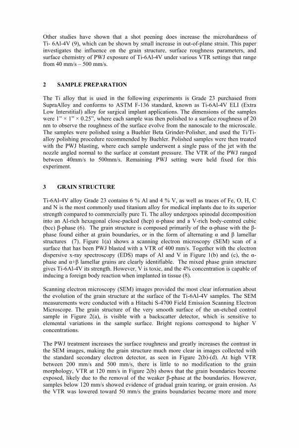
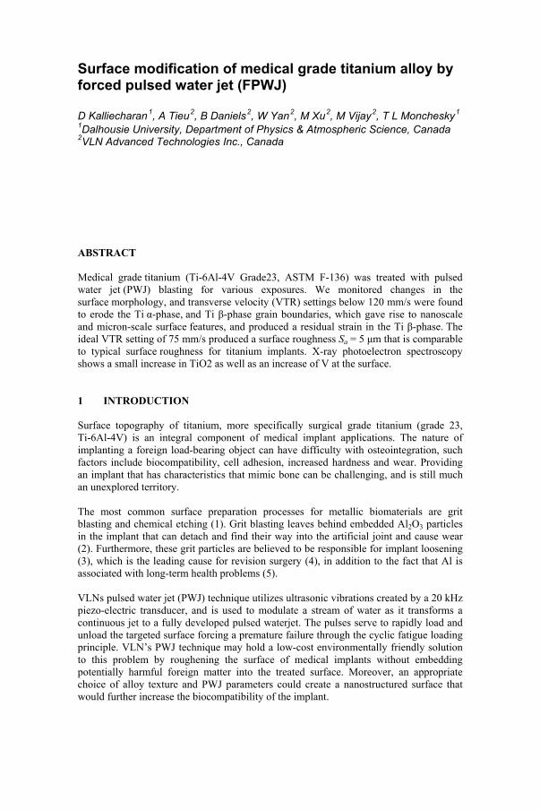
Other studies have shown that a shot peening does increase the microhardness of Ti- 6Al-4V (9), which can be shown by small increase in out-of-plane strain. This paper investigates the influence on the grain structure, surface roughness parameters, and surface chemistry of PWJ exposure of Ti-6Al-4V under various VTR settings that range from 40 mm/s – 500 mm/s. 2 SAMPLE PREPARATION The Ti alloy that is used in the following experiments is Grade 23 purchased from SupraAlloy and conforms to ASTM F-136 standard, known as Ti-6Al-4V ELI (Extra Low Interstitial) alloy for surgical implant applications. The dimensions of the samples were 1” × 1” × 0.25”, where each sample was then polished to a surface roughness of 20 nm to observe the roughness of the surface evolve from the nanoscale to the microscale. The samples were polished using a Buehler Beta Grinder-Polisher, and used the Ti/Ti-alloy polishing procedure recommended by Buehler. Polished samples were then treated with the PWJ blasting, where each sample underwent a single pass of the jet with the nozzle angled normal to the surface at constant pressure. The VTR of the PWJ ranged between 40mm/s to 500mm/s. Remaining PWJ setting were held fixed for this experiment. 3 GRAIN STRUCTURE Ti-6Al-4V alloy Grade 23 contains 6 % Al and 4 % V, as well as traces of Fe, O, H, C and N is the most commonly used titanium alloy for medical implants due to its superior strength compared to commercially pure Ti. The alloy undergoes spinodal decomposition into an Al-rich hexagonal close-packed (hcp) α-phase and a V-rich body-centred cubic (bcc) β-phase (6). The grain structure is composed primarily of the α-phase with the β-phase found either at grain boundaries, or in the form of alternating α and β lamellar structures (7). Figure 1(a) shows a scanning electron microscopy (SEM) scan of a surface that has been PWJ blasted with a VTR of 400 mm/s. Together with the electron dispersive x-ray spectroscopy (EDS) maps of Al and V in Figure 1(b) and (c), the α-phase and α+β lamellar grains are clearly identifiable. The mixed phase grain structure gives Ti-6Al-4V its strength. However, V is toxic, and the 4% concentration is capable of inducing a foreign body reaction when implanted in tissue (8). Scanning electron microscopy (SEM) images provided the most clear information about the evolution of the grain structure at the surface of the Ti-6Al-4V samples. The SEM measurements were conducted with a Hitachi S-4700 Field Emission Scanning Electron Microscope. The grain structure of the very smooth surface of the un-etched control sample in Figure 2(a), is visible with a backscatter detector, which is sensitive to elemental variations in the sample surface. Bright regions correspond to higher V concentrations. The PWJ treatment increases the surface roughness and greatly increases the contrast in the SEM images, making the grain structure much more clear in images collected with the standard secondary electron detector, as seen in Figure 2(b)-(d). At high VTR between 200 mm/s and 500 mm/s, there is little to no modification to the grain morphology, VTR at 120 mm/s in Figure 2(b) shows that the grain boundaries become exposed, likely due to the removal of the weaker β-phase at the boundaries. However, samples below 120 mm/s showed evidence of gradual grain tearing, or grain erosion. As the VTR was lowered toward 50 mm/s the grains boundaries became more and more
jagged to the point that individual grains became difficult to discern as shown in Figure 2(c) & (d). The evolution of the surface topography suggests that the PWJ treatments are ripping out grains from the surface at low VTR settings.
Figure 1: (a) SEM image Ti-6Al-4V sample exposed to a PWJ with VTR = 400 mm/s. (b) Al and (c) V EDS maps of the region shown in (a).
Figure 2: Backscattered electron image (a) and SEM images (b) - (d) of the PWJ
treated surfaces with varying VTR. The contrast in (a) derives from atomic number, where brighter regions contain higher V concentrations.
4 SURFACE ROUGHNESS We investigated the surface roughness with optical surface profilometry, atomic force microscopy (AFM), and surface wetting measurements. These techniques provide complementary information about the surface structure on a range of length scales. The surface roughness was characterized by the arithmetic average of the absolute surface height of all N points of the profile, Sa , also called the centre line average height (CLA), which is defined as (6)
N
iia xz
NS
1
|)(|1
(1)
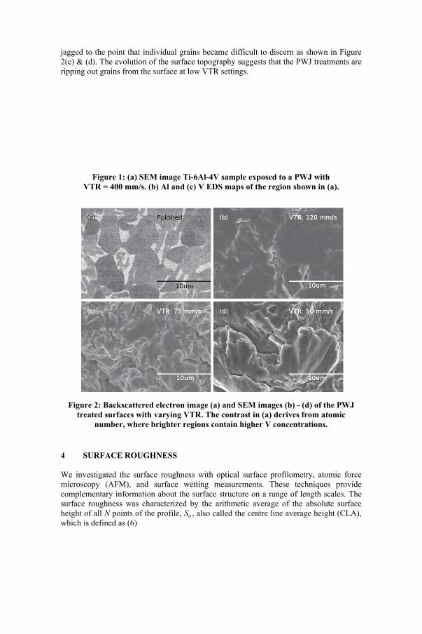
where z(xi) are the samples heights at horizontal positions xi. This is the 2D analogue of the metric Ra that measures the centre line average height across a line profile. Our reported Sa values from AFM measurements have the 2nd order background subtracted, whereas a constant background was removed in the optical profilometry measurements. We measured the Sa of the surface with a WYKO NT 9100 Optical Profilometer, which uses interferometry to determine surface height. The image size was 1.16 mm x 0.87 mm at a resolution of 640 x 480 pixels. The roughness for each sample was determined from the average of measurements from three separate regions, and plotted in Fig. 3.
Figure 3: The surface roughness factor Sa measured by optical profilometry.
The large error bars in VTR settings of 40 and 50 mm/s reflect large variations from region to region from a scan area of 1.16 mm x 0.87 mm. The surface
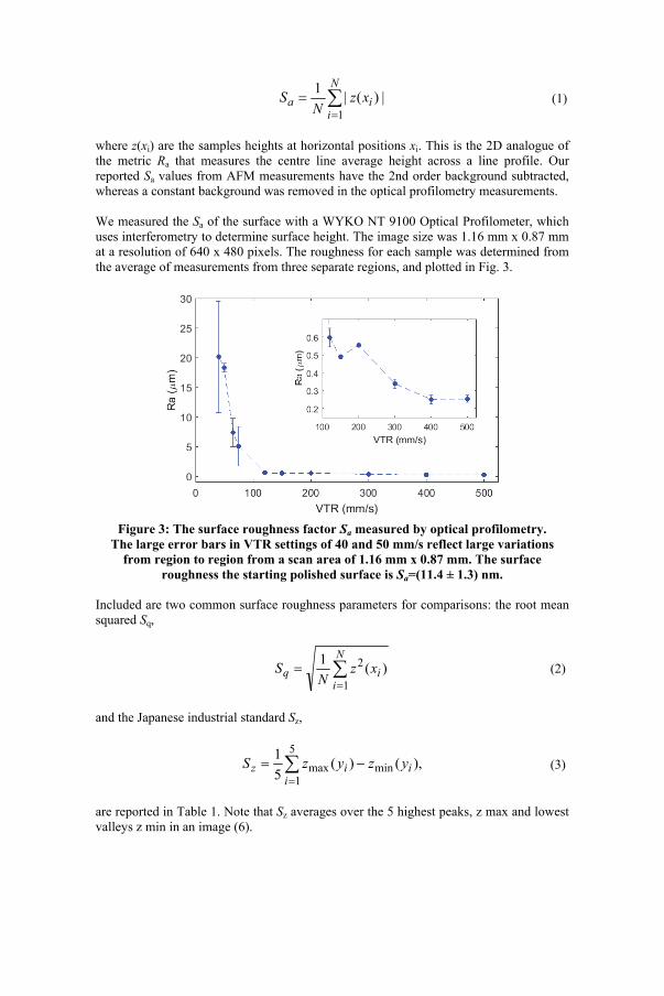
roughness the starting polished surface is Sa=(11.4 ± 1.3) nm. Included are two common surface roughness parameters for comparisons: the root mean squared Sq,
N
iiq xz
NS
1
2 )(1
(2)
and the Japanese industrial standard Sz,
5
1minmax ),()(
5
1
iiiz yzyzS
(3)
are reported in Table 1. Note that Sz averages over the 5 highest peaks, z max and lowest valleys z min in an image (6).
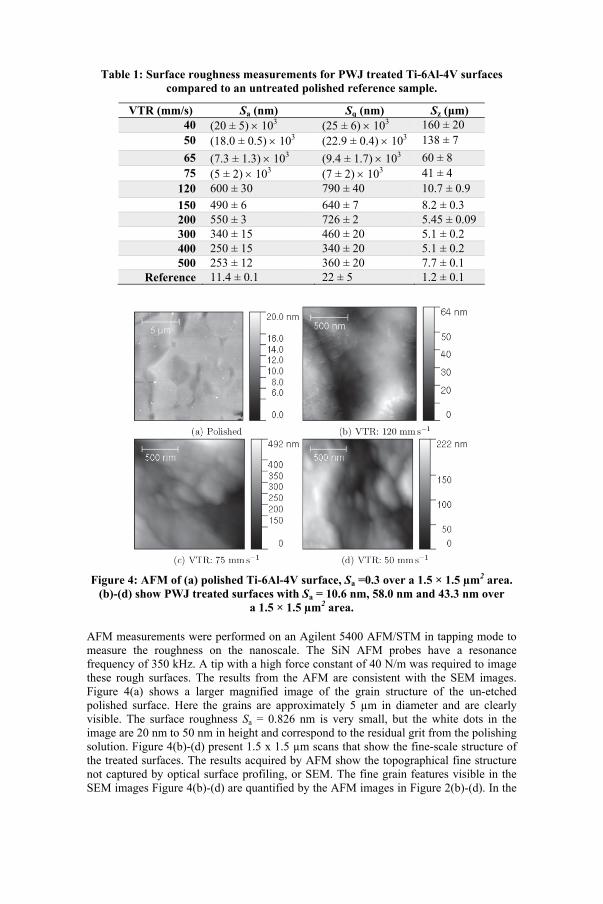
Table 1: Surface roughness measurements for PWJ treated Ti-6Al-4V surfaces compared to an untreated polished reference sample.
VTR (mm/s) Sa (nm) Sq (nm) Sz (μm) 40 (20 ± 5) 103 (25 ± 6) 103 160 ± 20 50 (18.0 ± 0.5) 103 (22.9 ± 0.4) 103 138 ± 7
65 (7.3 ± 1.3) 103 (9.4 ± 1.7) 103 60 ± 8 75 (5 ± 2) 103 (7 ± 2) 103 41 ± 4
120 600 ± 30 790 ± 40 10.7 ± 0.9
150 490 ± 6 640 ± 7 8.2 ± 0.3 200 550 ± 3 726 ± 2 5.45 ± 0.09 300 340 ± 15 460 ± 20 5.1 ± 0.2 400 250 ± 15 340 ± 20 5.1 ± 0.2 500 253 ± 12 360 ± 20 7.7 ± 0.1
Reference 11.4 ± 0.1 22 ± 5 1.2 ± 0.1
Figure 4: AFM of (a) polished Ti-6Al-4V surface, Sa =0.3 over a 1.5 × 1.5 µm2 area.
(b)-(d) show PWJ treated surfaces with Sa = 10.6 nm, 58.0 nm and 43.3 nm over a 1.5 × 1.5 µm2 area.
AFM measurements were performed on an Agilent 5400 AFM/STM in tapping mode to measure the roughness on the nanoscale. The SiN AFM probes have a resonance frequency of 350 kHz. A tip with a high force constant of 40 N/m was required to image these rough surfaces. The results from the AFM are consistent with the SEM images. Figure 4(a) shows a larger magnified image of the grain structure of the un-etched polished surface. Here the grains are approximately 5 µm in diameter and are clearly visible. The surface roughness Sa = 0.826 nm is very small, but the white dots in the image are 20 nm to 50 nm in height and correspond to the residual grit from the polishing solution. Figure 4(b)-(d) present 1.5 x 1.5 µm scans that show the fine-scale structure of the treated surfaces. The results acquired by AFM show the topographical fine structure not captured by optical surface profiling, or SEM. The fine grain features visible in the SEM images Figure 4(b)-(d) are quantified by the AFM images in Figure 2(b)-(d). In the
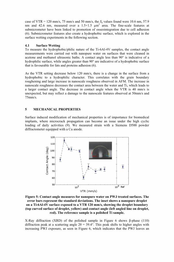
case of VTR = 120 mm/s, 75 mm/s and 50 mm/s, the Sa values found were 10.6 nm, 57.9 nm and 42.6 nm, measured over a 1.5×1.5 µm2 area. The fine-scale features at submicrometer have been linked to promotion of osseointegration due to cell adhesion (6). Submicrometer features also create a hydrophobic surface, which is explored in the surface wetting experiments in the following section. 4.1 Surface Wetting To measure the hydrophobic/philic nature of the Ti-6Al-4V samples, the contact angle measurements were carried out with nanopure water on surfaces that were cleaned in acetone and methanol ultrasonic baths. A contact angle less than 90° is indicative of a hydrophilic surface, while angles greater than 90° are indicative of a hydrophobic surface that is favourable for fats and proteins adhesion (6). As the VTR setting decrease below 120 mm/s, there is a change in the surface from a hydrophobic to a hydrophilic character. This correlates with the grain boundary roughening and large increase in nanoscale roughness observed in AFM. The increase in nanoscale roughness decreases the contact area between the water and Ti, which leads to a larger contact angle. The decrease in contact angle when the VTR is 40 mm/s is unexpected, but may reflect a damage to the nanoscale features observed at 50mm/s and 75mm/s. 5 MECHANICAL PROPERTIES Surface induced modification of mechanical properties is of importance for biomedical implants, where microcrack propagation can become an issue under the high cyclic loading of daily activities (9). We measured strain with a Siemens D500 powder diffractometer equipped with a Cu anode.
Figure 5: Contact angle measures for nanopure water on PWJ treated surfaces. The
error bars represent the standard deviations. The inset shows a nanopure droplet on a Ti-6Al-4V surface exposed to a VTR 120 mm/s, showing the droplet boundary
(top curved surface of droplet, yellow) and contact angle (left angled line on droplet, red). The reference sample is a polished Ti sample.
X-Ray diffraction (XRD) of the polished sample in Figure 6 shows β-phase (110) diffraction peak at a scattering angle 2θ = 39.4°. This peak shifts to higher angles with increasing PWJ exposure, as seen in Figure 6, which indicates that the PWJ leaves an

out-of-plane compressive strain in this phase. However, the α-phase (002) and (101) peaks at 38.5° and 40.4° do not change over the range of VTR settings. The measured strain obtained from fitting the peaks is shown in Figure 6(b). There is no evidence of residual strain found in the α-phase from either the diffraction peak position or the peak width.
Figure 6: (a) XRD θ-2θ scans for a series of PWJ treated Ti-6Al-4V samples for 40 mm/s ≤ VTR ≤ 500 mm/s. The scans are offset vertically for clarity.
(b) Strain determined from XRD. 6 CHEMICAL PROPERTIES 6.1 X-Ray Photoelectron Spectroscopy (XPS) We performed XPS measurements with a Thermo Scientific Multilab 3000, using a Mg Kα X-ray source. XPS shows that polishing increased the amount of Ti2O3 on the surface. The PWJ removes this chemically modified surface layer with a VTR ≤ 200 mm/s, as shown by the increase in the TiO2 2p3/2 and TiO2 2p1/2 signals. The surfaces treated with this exposure result in a small increase in the TiO2 relative to the un-etched polished samples, which is desirable for biocompatibility and chemical resistance (6).
Figure 7: XPS measurements in (a) show the amount of TiO2 and Ti2O3 relative to the total signal from Ti. An example XPS spectra is show in (b) for VTR = 120 mm/s, with the individual components of the fit corresponding to TiO2,
Ti2O3 and Ti-metal.
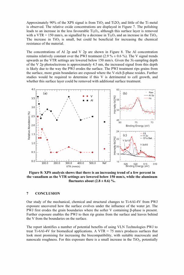
Approximately 90% of the XPS signal is from TiO2 and Ti2O3 and little of the Ti metal is observed. The relative oxide concentrations are displayed in Figure 7. The polishing leads to an increase in the less favourable Ti2O3, although this surface layer is removed with a VTR = 150 mm/s, as signalled by a decrease in Ti2O3 and an increase in the TiO2. The increase in TiO2 is small, but could be beneficial for increasing the chemical resistance of the material. The concentrations of Al 2p and V 2p are shown in Figure 8. The Al concentration remains relatively constant over the PWJ treatment (2.9 % ± 0.6 %). The V signal trends upwards as the VTR settings are lowered below 150 mm/s. Given the 3λ-sampling depth of the V 2p photoelectrons is approximately 4.5 nm, the increased signal from this depth is likely due to the way the PWJ erodes the surface. The PWJ treatment rips grains from the surface, more grain boundaries are exposed where the V-rich β-phase resides. Further studies would be required to determine if this V is detrimental to cell growth, and whether this surface layer could be removed with additional surface treatment.
Figure 8: XPS analysis shows that there is an increasing trend of a few percent in
the vanadium as the VTR settings are lowered below 150 mm/s, while the aluminum fluctuates about (2.8 ± 0.6) %.
7 CONCLUSION Our study of the mechanical, chemical and structural changes to Ti-6Al-4V from PWJ exposure uncovered how the surface evolves under the influence of the water jet. The PWJ first erodes the grain boundaries where the softer V containing β-phase is present. Further exposure enables the PWJ to then rip grains from the surface and leaves behind the V from the boundaries on the surface. The report identifies a number of potential benefits of using VLN Technologies PWJ to treat Ti-6Al-4V for biomedical applications. A VTR = 75 mm/s produces surfaces that look most promising for increasing the biocompatibility, with suitable macroscale and nanoscale roughness. For this exposure there is a small increase in the TiO2, potentially
improving its chemical inertness. The residual strain in the surface could also increase the mechanical strength of the surface, although little is known to date on the benefits of surface hardness for medical implants (9). 8 ACKNOWLEDGEMENTS We would like to thank Dr. Stephen Corbin for his guidance understanding the grain structure on Ti-6Al-4V. In addition, Julian O’Flynn, and Colin Tadgell from Dr. Corbins group for assistance with the microindenter operation and sample preparation. Dr. Kevin Plucknett for useful discussions. Andrew George, for his help with XPS measurements and analysis and technical assistance with the diffractometer. We would also like to thank Laurent Kreplak for technical assistance with the AFM. We acknowledge support from NSERC and the support of the Canada Foundation for Innovation, the Atlantic Innovation Fund, and other partners which fund the Facilities for Materials Characterization, managed by the Institute for Research in Materials. 9 REFERENCES 1. Assessment of blasting induced effects on medical 316 LVM stainless steel by
contacting and non-contacting thermoelectric power techniques. H. Carreon, S. Barriuso, G. Barrera, J. L. Gonzalez-Carrasco, and F. G. Caballero. 2012, Surface and Coatings Technology, Vol. 206, pp. 2941-2946.
2. Adverse tissue reactions to wear particles from co-alloy articulations, increased by alumina blasting particle contamination from cementless ti-based total hip implants: A report of seven revisions with early failure. M. Böhler, F. Kanz, B. Schwarz, I. Steffan, A. Walter, H. Plenk, and K. Knahr. 2002, Journal of Bone and Joint Surgery, Vol. 84B, pp. 128-136.
3. A cementless hip system with a new surface for osseous integration. R. Lass, Alexander Kolb, G. Skrbensky, G. Reinisch, B. Kubista, A. Giurea, R. Windhager, and Rainer Kotz. 2014, International Orthopaedics, Vol. 38, pp. 703-709.
4. Canadian Institute for Health Information. Hip and Knee Replacements in Canada: Canadian Joint Replacement Registry 2014 Annual Report. 2014.
5. Ti based biomaterials, the ultimate choice for orthopaedic implants -a review. M. Geetha, A. K. Singh, R. Asokamani, and A. K. Gogia. 2009, Progress in Materials Science, Vol. 54, pp. 397-425.
6. D. M. Brunette, P. Tengvall, M. Textor, P. Thomsen. Titanium in Medicine: Material Science, Surface Science, Engineering, Biological Responses and Medical Applications. s.l. : Springer, 2001.
7. R. Wanhill, and S. Barter. Fatigue of beta processed and beta heat-treated titanium alloys. SpringerBriefs in Applied Sciences and Technology. s.l. : Springer, 2012.
8. Titanium the material of choice? Steinemann, S. G. 721, 2000, Periodontology, Vol. 17.
9. Fatigue Performance of Medical Ti6Al4V Alloy after Mechanical Surface Treatments. R. Sonntag, J. Reinders, J. Gibmeier, J. P. Kretzer. 2015, PLos ONE 10(3):ee01231963.