support rand for more information€¦ · shared modular build of warships how a shared build can...
TRANSCRIPT

For More InformationVisit RAND at www.rand.org
Explore the RAND National Defense Research Institute
View document details
Support RANDPurchase this document
Browse Reports & Bookstore
Make a charitable contribution
Limited Electronic Distribution RightsThis document and trademark(s) contained herein are protected by law as indicated in a notice appearing later in this work. This electronic representation of RAND intellectual property is provided for non-commercial use only. Unauthorized posting of RAND electronic documents to a non-RAND website is prohibited. RAND electronic documents are protected under copyright law. Permission is required from RAND to reproduce, or reuse in another form, any of our research documents for commercial use. For information on reprint and linking permissions, please see RAND Permissions.
Skip all front matter: Jump to Page 16
The RAND Corporation is a nonprofit institution that helps improve policy and decisionmaking through research and analysis.
This electronic document was made available from www.rand.org as a public service of the RAND Corporation.
CHILDREN AND FAMILIES
EDUCATION AND THE ARTS
ENERGY AND ENVIRONMENT
HEALTH AND HEALTH CARE
INFRASTRUCTURE AND TRANSPORTATION
INTERNATIONAL AFFAIRS
LAW AND BUSINESS
NATIONAL SECURITY
POPULATION AND AGING
PUBLIC SAFETY
SCIENCE AND TECHNOLOGY
TERRORISM AND HOMELAND SECURITY

This product is part of the RAND Corporation technical report series. Reports may
include research findings on a specific topic that is limited in scope; present discussions
of the methodology employed in research; provide literature reviews, survey instru-
ments, modeling exercises, guidelines for practitioners and research professionals, and
supporting documentation; or deliver preliminary findings. All RAND reports un-
dergo rigorous peer review to ensure that they meet high standards for research quality
and objectivity.

NATIONAL DEFENSE RESEARCH INSTITUTE
REPORT
Shared Modular Build of Warships
How a Shared Build Can Support Future Shipbuilding
Laurence Smallman • Hanlin Tang • John F. Schank • Stephanie Pezard
Prepared for the United States Navy
Approved for public release; distribution unlimited

The RAND Corporation is a nonprofit institution that helps improve policy and decisionmaking through research and analysis. RAND’s publications do not necessarily reflect the opinions of its research clients and sponsors.
R® is a registered trademark.
© Copyright 2011 RAND Corporation
Permission is given to duplicate this document for personal use only, as long as it is unaltered and complete. Copies may not be duplicated for commercial purposes. Unauthorized posting of RAND documents to a non-RAND website is prohibited. RAND documents are protected under copyright law. For information on reprint and linking permissions, please visit the RAND permissions page (http://www.rand.org/publications/ permissions.html).
Published 2011 by the RAND Corporation1776 Main Street, P.O. Box 2138, Santa Monica, CA 90407-2138
1200 South Hayes Street, Arlington, VA 22202-50504570 Fifth Avenue, Suite 600, Pittsburgh, PA 15213-2665
RAND URL: http://www.rand.orgTo order RAND documents or to obtain additional information, contact
Distribution Services: Telephone: (310) 451-7002; Fax: (310) 451-6915; Email: [email protected]
Library of Congress Control Number: 2011924089
ISBN: 978-0-8330-5148-6
Cover photo by DCNS: The bow section of the Mistral is brought into position with the stern section in Brest, France, July 2004.
The research described in this report was prepared for the United States Navy. The research was conducted within the RAND National Defense Research Institute, a federally funded research and development center sponsored by the Office of the Secretary of Defense, the Joint Staff, the Unified Combatant Commands, the Navy, the Marine Corps, the defense agencies, and the defense Intelligence Community under Contract W74V8H-06-C-0002.

iii
Preface
Some recent shipbuilding programs in the United States and Europe have involved multi-ple shipyards constructing major modules of each ship for final integration and test at one shipyard. This approach, a shared build of a warship, might be adopted for many reasons. It requires close coordination and planning among shipyards to identify and manage risks.
Recognizing that shared build might be an option for future shipbuilding programs, the U.S. Navy Program Office for the Future Cruiser (CG[X]) asked the RAND Corporation to examine several recent shared-build programs in the United States and Europe and identify the key decisions, advantages, and disadvantages associated with them. This document sum-marizes our work. It should be of interest to policymakers and others concerned about ship construction and the maritime industrial base.
This research was sponsored by the U.S. Navy Program Office for CG(X) and con-ducted within the Acquisition and Technology Policy Center of the RAND National Defense Research Institute, a federally funded research and development center sponsored by the Office of the Secretary of Defense, the Joint Staff, the Unified Combatant Commands, the Navy, the Marine Corps, the defense agencies, and the defense Intelligence Community.
For more information on the RAND Acquisition and Technology Policy Center, see http://www.rand.org/nsrd/about/atp.html or contact the director (contact information is pro-vided on the web page).

v
Contents
Preface . . . . . . . . . . . . . . . . . . . . . . . . . . . . . . . . . . . . . . . . . . . . . . . . . . . . . . . . . . . . . . . . . . . . . . . . . . . . . . . . . . . . . . . . . . . . . . . . . . . . . . . . . . . iiiFigures . . . . . . . . . . . . . . . . . . . . . . . . . . . . . . . . . . . . . . . . . . . . . . . . . . . . . . . . . . . . . . . . . . . . . . . . . . . . . . . . . . . . . . . . . . . . . . . . . . . . . . . . . . . viiTables . . . . . . . . . . . . . . . . . . . . . . . . . . . . . . . . . . . . . . . . . . . . . . . . . . . . . . . . . . . . . . . . . . . . . . . . . . . . . . . . . . . . . . . . . . . . . . . . . . . . . . . . . . . . ixSummary . . . . . . . . . . . . . . . . . . . . . . . . . . . . . . . . . . . . . . . . . . . . . . . . . . . . . . . . . . . . . . . . . . . . . . . . . . . . . . . . . . . . . . . . . . . . . . . . . . . . . . . . xiAcknowledgments . . . . . . . . . . . . . . . . . . . . . . . . . . . . . . . . . . . . . . . . . . . . . . . . . . . . . . . . . . . . . . . . . . . . . . . . . . . . . . . . . . . . . . . . . . . xviiAbbreviations . . . . . . . . . . . . . . . . . . . . . . . . . . . . . . . . . . . . . . . . . . . . . . . . . . . . . . . . . . . . . . . . . . . . . . . . . . . . . . . . . . . . . . . . . . . . . . . . . . xix
CHAPTER ONE
Introduction . . . . . . . . . . . . . . . . . . . . . . . . . . . . . . . . . . . . . . . . . . . . . . . . . . . . . . . . . . . . . . . . . . . . . . . . . . . . . . . . . . . . . . . . . . . . . . . . . . . . . 1Approach . . . . . . . . . . . . . . . . . . . . . . . . . . . . . . . . . . . . . . . . . . . . . . . . . . . . . . . . . . . . . . . . . . . . . . . . . . . . . . . . . . . . . . . . . . . . . . . . . . . . . . . . . . 1Structure of This Report . . . . . . . . . . . . . . . . . . . . . . . . . . . . . . . . . . . . . . . . . . . . . . . . . . . . . . . . . . . . . . . . . . . . . . . . . . . . . . . . . . . . . . . . 2
CHAPTER TWO
Choosing Shared Build . . . . . . . . . . . . . . . . . . . . . . . . . . . . . . . . . . . . . . . . . . . . . . . . . . . . . . . . . . . . . . . . . . . . . . . . . . . . . . . . . . . . . . . . 3Specifying Shared Build . . . . . . . . . . . . . . . . . . . . . . . . . . . . . . . . . . . . . . . . . . . . . . . . . . . . . . . . . . . . . . . . . . . . . . . . . . . . . . . . . . . . . . . . . 3
CHAPTER THREE
Workload-Allocation Strategies . . . . . . . . . . . . . . . . . . . . . . . . . . . . . . . . . . . . . . . . . . . . . . . . . . . . . . . . . . . . . . . . . . . . . . . . . . . . . . 7
CHAPTER FOUR
Contractual Arrangements. . . . . . . . . . . . . . . . . . . . . . . . . . . . . . . . . . . . . . . . . . . . . . . . . . . . . . . . . . . . . . . . . . . . . . . . . . . . . . . . . . . 11Alliance Structure . . . . . . . . . . . . . . . . . . . . . . . . . . . . . . . . . . . . . . . . . . . . . . . . . . . . . . . . . . . . . . . . . . . . . . . . . . . . . . . . . . . . . . . . . . . . . . . 11Prime and Subcontractor Structures . . . . . . . . . . . . . . . . . . . . . . . . . . . . . . . . . . . . . . . . . . . . . . . . . . . . . . . . . . . . . . . . . . . . . . . . . . 11Government-to-Contractor-Only Structure . . . . . . . . . . . . . . . . . . . . . . . . . . . . . . . . . . . . . . . . . . . . . . . . . . . . . . . . . . . . . . . . . 12
CHAPTER FIVE
Design Software and Information Technology Systems . . . . . . . . . . . . . . . . . . . . . . . . . . . . . . . . . . . . . . . . . . . . . . . 15
CHAPTER SIX
Cost Implications . . . . . . . . . . . . . . . . . . . . . . . . . . . . . . . . . . . . . . . . . . . . . . . . . . . . . . . . . . . . . . . . . . . . . . . . . . . . . . . . . . . . . . . . . . . . . . 17Learning-Curve Effects . . . . . . . . . . . . . . . . . . . . . . . . . . . . . . . . . . . . . . . . . . . . . . . . . . . . . . . . . . . . . . . . . . . . . . . . . . . . . . . . . . . . . . . . . 17
CHAPTER SEVEN
Shipyard Collaboration During Shared Build . . . . . . . . . . . . . . . . . . . . . . . . . . . . . . . . . . . . . . . . . . . . . . . . . . . . . . . . . . 23

vi Shared Modular Build of Warships: How a Shared Build Can Support Future Shipbuilding
CHAPTER EIGHT
Comments . . . . . . . . . . . . . . . . . . . . . . . . . . . . . . . . . . . . . . . . . . . . . . . . . . . . . . . . . . . . . . . . . . . . . . . . . . . . . . . . . . . . . . . . . . . . . . . . . . . . . . 27Risks to Shared-Build Programs . . . . . . . . . . . . . . . . . . . . . . . . . . . . . . . . . . . . . . . . . . . . . . . . . . . . . . . . . . . . . . . . . . . . . . . . . . . . . . 29
Motivating Cooperation . . . . . . . . . . . . . . . . . . . . . . . . . . . . . . . . . . . . . . . . . . . . . . . . . . . . . . . . . . . . . . . . . . . . . . . . . . . . . . . . . . . . . 29Design Completion . . . . . . . . . . . . . . . . . . . . . . . . . . . . . . . . . . . . . . . . . . . . . . . . . . . . . . . . . . . . . . . . . . . . . . . . . . . . . . . . . . . . . . . . . . . 29Design and Design-to-Production Organization . . . . . . . . . . . . . . . . . . . . . . . . . . . . . . . . . . . . . . . . . . . . . . . . . . . . . . . . . 29Aligning Production Practices and Schedules . . . . . . . . . . . . . . . . . . . . . . . . . . . . . . . . . . . . . . . . . . . . . . . . . . . . . . . . . . . . 30
Costs of Shared-Build Programs . . . . . . . . . . . . . . . . . . . . . . . . . . . . . . . . . . . . . . . . . . . . . . . . . . . . . . . . . . . . . . . . . . . . . . . . . . . . . 30
APPENDICES
A. DDG-51 Deckhouse Case Study . . . . . . . . . . . . . . . . . . . . . . . . . . . . . . . . . . . . . . . . . . . . . . . . . . . . . . . . . . . . . . . . . . . . . . . 33B. DDG-1000 Case Study . . . . . . . . . . . . . . . . . . . . . . . . . . . . . . . . . . . . . . . . . . . . . . . . . . . . . . . . . . . . . . . . . . . . . . . . . . . . . . . . . . 37C. LPD-17 Case Study . . . . . . . . . . . . . . . . . . . . . . . . . . . . . . . . . . . . . . . . . . . . . . . . . . . . . . . . . . . . . . . . . . . . . . . . . . . . . . . . . . . . . . 43D. Virginia Case Study . . . . . . . . . . . . . . . . . . . . . . . . . . . . . . . . . . . . . . . . . . . . . . . . . . . . . . . . . . . . . . . . . . . . . . . . . . . . . . . . . . . . . . 49E. UK Type 45 Destroyer Case Study . . . . . . . . . . . . . . . . . . . . . . . . . . . . . . . . . . . . . . . . . . . . . . . . . . . . . . . . . . . . . . . . . . . . 55F. UK Future Carrier Case Study . . . . . . . . . . . . . . . . . . . . . . . . . . . . . . . . . . . . . . . . . . . . . . . . . . . . . . . . . . . . . . . . . . . . . . . . . 65G. LHD Mistral and Tonnerre . . . . . . . . . . . . . . . . . . . . . . . . . . . . . . . . . . . . . . . . . . . . . . . . . . . . . . . . . . . . . . . . . . . . . . . . . . . . . 73
Bibliography . . . . . . . . . . . . . . . . . . . . . . . . . . . . . . . . . . . . . . . . . . . . . . . . . . . . . . . . . . . . . . . . . . . . . . . . . . . . . . . . . . . . . . . . . . . . . . . . . . . . 79

vii
Figures
6.1. Learning-Curve Effect of Alternating Hulls Between Shipyards . . . . . . . . . . . . . . . . . . . . . . . . . . . . 18 6.2. Cost Premiums Associated with Shared Learning in an Alternating-Build Strategy . . . . . . 19 A.1. View of the DDG-103 Deckhouse After an Electrical Fire . . . . . . . . . . . . . . . . . . . . . . . . . . . . . . . . . . . 33 A.2. DDG-51 Sections . . . . . . . . . . . . . . . . . . . . . . . . . . . . . . . . . . . . . . . . . . . . . . . . . . . . . . . . . . . . . . . . . . . . . . . . . . . . . . . . . 34 A.3. Shipyards Involved in the Construction of DDG-103 . . . . . . . . . . . . . . . . . . . . . . . . . . . . . . . . . . . . . . . . 35 B.1. Bath Iron Works–Northrop Grumman Shared-Build Plan . . . . . . . . . . . . . . . . . . . . . . . . . . . . . . . . . 38 B.2. Shipyards Involved in the Construction of DDG-1000 . . . . . . . . . . . . . . . . . . . . . . . . . . . . . . . . . . . . . . 41 C.1. LPD-24 Inboard Profile: Assembly Units . . . . . . . . . . . . . . . . . . . . . . . . . . . . . . . . . . . . . . . . . . . . . . . . . . . . . . 44 C.2. Example LPD-24 Unit Being Lifted at Bath Iron Works . . . . . . . . . . . . . . . . . . . . . . . . . . . . . . . . . . . . 44 C.3. Example LPD-24 Unit Under Construction at Bath Iron Works . . . . . . . . . . . . . . . . . . . . . . . . . . . . 45 C.4. Shipyards Involved in the Construction of LPD-24 . . . . . . . . . . . . . . . . . . . . . . . . . . . . . . . . . . . . . . . . . . 46 D.1. Work-Share Agreement by Electric Boat and Northrop Grumman Shipbuilding—
Newport News for Virginia-Class Submarines . . . . . . . . . . . . . . . . . . . . . . . . . . . . . . . . . . . . . . . . . . . . . . . . 50 D.2. A Supermodule Sits Aboard the Sea Shuttle at Quonset Point . . . . . . . . . . . . . . . . . . . . . . . . . . . . . . . 53 D.3. Shipyards Involved in the Construction of the Virginia Class . . . . . . . . . . . . . . . . . . . . . . . . . . . . . . 54 E.1. The Type 45 Destroyer . . . . . . . . . . . . . . . . . . . . . . . . . . . . . . . . . . . . . . . . . . . . . . . . . . . . . . . . . . . . . . . . . . . . . . . . . . . . 55 E.2. Type 45 Blocks . . . . . . . . . . . . . . . . . . . . . . . . . . . . . . . . . . . . . . . . . . . . . . . . . . . . . . . . . . . . . . . . . . . . . . . . . . . . . . . . . . . . . 58 E.3. Shipyards Involved in Construction of the Type 45 Class in 2006 . . . . . . . . . . . . . . . . . . . . . . . . . . 59 E.4. Type 45 Bow Section on Barge Moving from Portsmouth to Glasgow . . . . . . . . . . . . . . . . . . . . . 61 E.5. Type 45 Forecast Learning Curve . . . . . . . . . . . . . . . . . . . . . . . . . . . . . . . . . . . . . . . . . . . . . . . . . . . . . . . . . . . . . . . 62 F.1. Shipyards Involved in the Construction of the Queen Elizabeth–Class Aircraft
Carrier . . . . . . . . . . . . . . . . . . . . . . . . . . . . . . . . . . . . . . . . . . . . . . . . . . . . . . . . . . . . . . . . . . . . . . . . . . . . . . . . . . . . . . . . . . . . . . 66 F.2. Block Assignment for HMS Queen Elizabeth, First of Class of the QEC . . . . . . . . . . . . . . . . . . . 69 F.3. Early Stages of Construction of HMS Queen Elizabeth Lower Block 3 at BAE
Systems Surface Ships Govan Shipyard . . . . . . . . . . . . . . . . . . . . . . . . . . . . . . . . . . . . . . . . . . . . . . . . . . . . . . . . . 69 F.4. Widening Work on Rosyth Dock 1 . . . . . . . . . . . . . . . . . . . . . . . . . . . . . . . . . . . . . . . . . . . . . . . . . . . . . . . . . . . . . 70 G.1. Shipyards Involved in the Construction of the Mistral Class. . . . . . . . . . . . . . . . . . . . . . . . . . . . . . . . . 74 G.2. Building of the Rear Section of the Mistral by Direction des Constructions Navales
in Brest, September 2003 . . . . . . . . . . . . . . . . . . . . . . . . . . . . . . . . . . . . . . . . . . . . . . . . . . . . . . . . . . . . . . . . . . . . . . . . . 75 G.3. Arrival in Brest of Blocks 2 and 3 Built in Poland on a Barge Towed by the Tug
Atlant . . . . . . . . . . . . . . . . . . . . . . . . . . . . . . . . . . . . . . . . . . . . . . . . . . . . . . . . . . . . . . . . . . . . . . . . . . . . . . . . . . . . . . . . . . . . . . . 77


ix
Tables
S.1. Characteristics of Shared-Build Programs Studied . . . . . . . . . . . . . . . . . . . . . . . . . . . . . . . . . . . . . . . . . . . . xii 2.1. Rationales for Shared-Build Cases . . . . . . . . . . . . . . . . . . . . . . . . . . . . . . . . . . . . . . . . . . . . . . . . . . . . . . . . . . . . . . . . 5 3.1. Role of Capability Constraints in Shared-Build Cases . . . . . . . . . . . . . . . . . . . . . . . . . . . . . . . . . . . . . . . . . 9 4.1. Contractual Arrangements in Shared-Build Cases . . . . . . . . . . . . . . . . . . . . . . . . . . . . . . . . . . . . . . . . . . . . 13 5.1. Design Issues in Shared-Build Cases . . . . . . . . . . . . . . . . . . . . . . . . . . . . . . . . . . . . . . . . . . . . . . . . . . . . . . . . . . . . 16 6.1. Build-Strategy Cost Characteristics . . . . . . . . . . . . . . . . . . . . . . . . . . . . . . . . . . . . . . . . . . . . . . . . . . . . . . . . . . . . 20 6.2. Cost Implications of Shared-Build Cases . . . . . . . . . . . . . . . . . . . . . . . . . . . . . . . . . . . . . . . . . . . . . . . . . . . . . . . 21 7.1. Shipyard Collaboration in Shared-Build Cases . . . . . . . . . . . . . . . . . . . . . . . . . . . . . . . . . . . . . . . . . . . . . . . . 25 8.1. Characteristics of Shared-Build Programs Studied . . . . . . . . . . . . . . . . . . . . . . . . . . . . . . . . . . . . . . . . . . . 28 C.1. Shared Build of LPD-17–Class Ships. . . . . . . . . . . . . . . . . . . . . . . . . . . . . . . . . . . . . . . . . . . . . . . . . . . . . . . . . . . 43 E.1. Ships of the Type 45 Class and Launch Dates . . . . . . . . . . . . . . . . . . . . . . . . . . . . . . . . . . . . . . . . . . . . . . . . 56 E.2. Summary of Risks and Rewards of Alternative Acquisition Strategies for the Type 45 . . . 58


xi
Summary
Why would a warship program follow a multiple-yard, modular-build strategy? And how might such a program be managed to deliver those warships? This report sets out to answer these questions by considering the theoretical cost advantages, benefits, and challenges of building warships in modules at multiple yards with final assembly at a single shipyard: the shared-build approach. The basis for this analysis is the case studies of recent shared-build warship programs in the United States, France, and the United Kingdom (UK). We do not prescribe specific steps to take; rather, we draw out key points and themes from the case studies and analyze these. In this way, decision makers and future program managers can draw on the experiences of others who might have faced similar challenges.
There are three circumstances under which a multiple-shipyard, modular-build strategy might be adopted: A customer might specify the requirement; a prime-contracting shipyard might plan to outsource elements of construction; or an event in a build shipyard might lead to unplanned outsourcing of some of the work. Shared build might be required for political reasons, such as to provide work to more than one geographic region or maintain a shipbuild-ing industrial base, or it might be needed to access skills available only at different shipyards or to overcome capacity constraints. In some circumstances, it might be hoped that shared build could reduce costs.
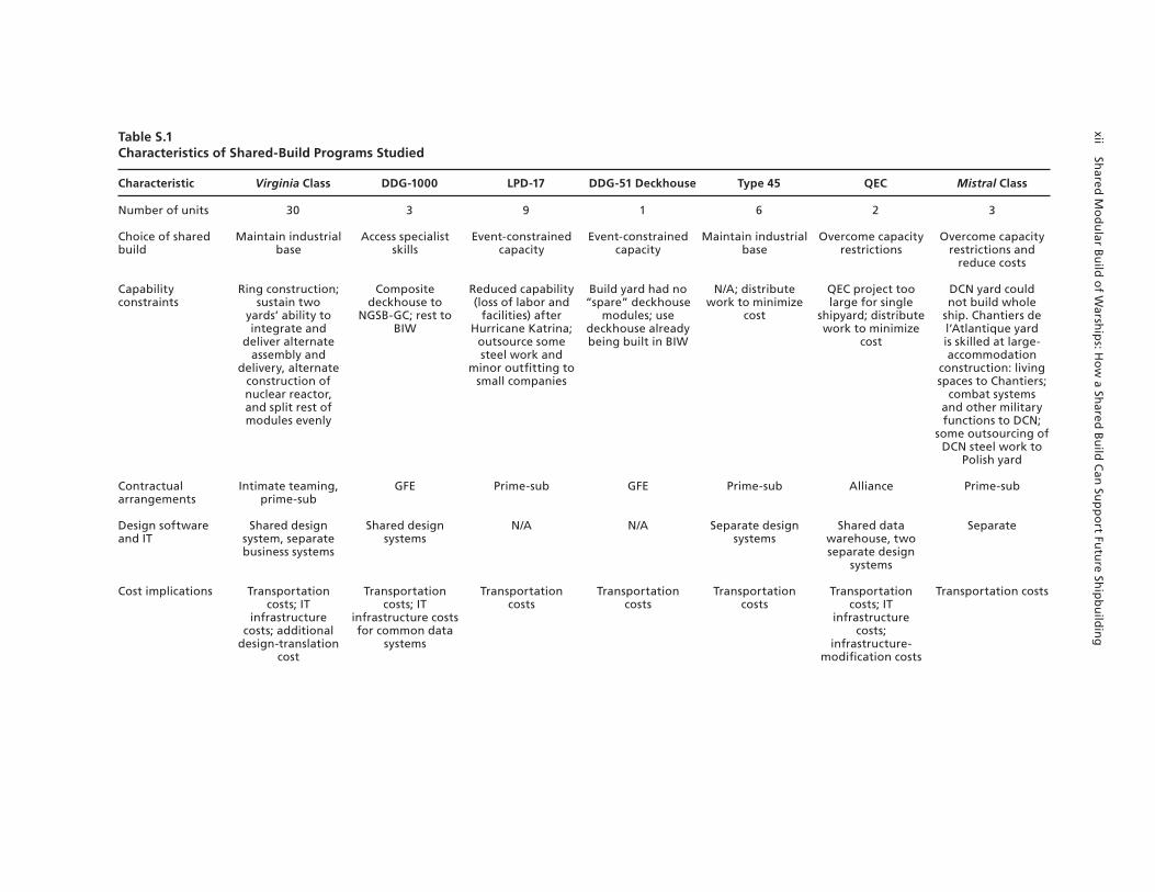
The case studies are used to investigate such factors, and we use these to describe the key elements that decision makers might wish to consider as they contemplate the available strategies for delivering a class of warship. It might be that lawmakers direct the requirement for sharing build to maintain work and support an industrial base. Program managers and the potential shipyards will want to carefully plan the workload allocations to deliver the ves-sels within budget. Choices will need to be made about the contractual structure that will best meet the program’s needs, and those involved will need to consider how they will work together, both in design and production, so that their collaboration helps and does not hinder the program. Table S.1 summarizes the attributes of the different shared- or modular-build cases.
There are no irresolvable technical obstacles to a shared-build strategy. Although shared build can work, it might not always deliver the outcome expected when the decision to adopt it is first made. For example, it might not maintain skills at all shipyards equally. Also, there are likely to be extra costs associated with such duplicated capability if hull numbers and drum-beat are not carefully managed.1 Further, it is not clear that shared build is an effective means of preserving competition. This is because success in a shared-build program, particularly for
1 Drumbeat is the build-schedule periodicity and is usually measured by the start of construction of each hull.
xii Shared
Mo
du
lar Bu
ild o
f Warsh
ips: H
ow
a Shared
Bu
ild C
an Su
pp
ort Fu
ture Sh
ipb
uild
ing
Table S.1Characteristics of Shared-Build Programs Studied
Characteristic Virginia Class DDG-1000 LPD-17 DDG-51 Deckhouse Type 45 QEC Mistral Class
Number of units 30 3 9 1 6 2 3
Choice of shared build
Maintain industrial base
Access specialist skills
Event-constrained capacity
Event-constrained capacity
Maintain industrial base
Overcome capacity restrictions
Overcome capacity restrictions and
reduce costs
Capability constraints
Ring construction; sustain two
yards’ ability to integrate and
deliver alternate assembly and
delivery, alternate construction of nuclear reactor, and split rest of modules evenly
Composite deckhouse to
NGSB-GC; rest to BIW
Reduced capability (loss of labor and
facilities) after Hurricane Katrina;
outsource some steel work and
minor outfitting to small companies
Build yard had no “spare” deckhouse
modules; use deckhouse already being built in BIW
N/A; distribute work to minimize
cost
QEC project too large for single
shipyard; distribute work to minimize
cost
DCN yard could not build whole
ship. Chantiers de l’Atlantique yard is skilled at large-accommodation
construction: living spaces to Chantiers;
combat systems and other military functions to DCN;
some outsourcing of DCN steel work to
Polish yard
Contractual arrangements
Intimate teaming, prime-sub
GFE Prime-sub GFE Prime-sub Alliance Prime-sub
Design software and IT
Shared design system, separate business systems
Shared design systems
N/A N/A Separate design systems
Shared data warehouse, two separate design
systems
Separate
Cost implications Transportation costs; IT
infrastructure costs; additional
design-translation cost
Transportation costs; IT
infrastructure costs for common data
systems
Transportation costs
Transportation costs
Transportation costs
Transportation costs; IT
infrastructure costs;
infrastructure-modification costs
Transportation costs

Sum
mary xiii
Characteristic Virginia Class DDG-1000 LPD-17 DDG-51 Deckhouse Type 45 QEC Mistral Class
Shipyard collaboration
Extensive collaboration at all levels of
management and production
Integration-yard QA personnel at
supply yards
Minimal collaboration
Some collaboration Integration-yard QA personnel at
supply yard
Fully integrated program
management; integration-yard QA personnel at
supply yard
None
NOTE: DDG-1000 = Zumwalt-class destroyer. LPD-17 = San Antonio–class dock. DDG-51 = Arleigh Burke–class destroyer. Type 45 = Daring-class destroyer (UK). QEC = Queen Elizabeth–class aircraft carrier. NGSB-GC = Northrop Grumman Shipbuilding—Gulf Coast. BIW = Bath Iron Works. DCN = Direction des Constructions Navales. GFE = government-furnished equipment. IT = information technology. QA = quality assurance.
Table S.1—Continued
xiv Shared Modular Build of Warships: How a Shared Build Can Support Future Shipbuilding
complex vessels, requires the cooperating shipyards to set aside any competitive tendencies and help each other to the overall benefit of the program. The prospect of future competition will inhibit such a process, as was seen in the early stages of the UK’s Type 45 program. Conversely, shipyards in a successful shared-build program seem keen to remain in such a structure for subsequent work. The teaming arrangement delivering the Virginia-class submarines reinforces this observation; the UK’s alliance structure for delivering the future carriers evolved from multiple shipyards via a joint venture to a single shipyard. We conclude that the government (or Navy) needs to decide what it wants from a shared-build strategy before embarking on it. Once a decision is made, the program manager must then monitor and manage the program to ensure that it delivers the required outcome, as well as the vessels called for in the program.
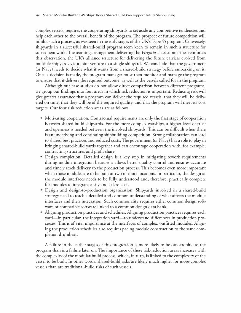
Although our case studies do not allow direct comparison between different programs, we group our findings into four areas in which risk reduction is important. Reducing risk will give greater assurance that a program can deliver the required vessels, that they will be deliv-ered on time, that they will be of the required quality, and that the program will meet its cost targets. Our four risk reduction areas are as follows:
• Motivating cooperation. Contractual requirements are only the first stage of cooperation between shared-build shipyards. For the more-complex warships, a higher level of trust and openness is needed between the involved shipyards. This can be difficult when there is an underlying and continuing shipbuilding competition. Strong collaboration can lead to shared best practices and reduced costs. The government (or Navy) has a role to play in bringing shared-build yards together and can encourage cooperation with, for example, contracting structures and profit share.
• Design completion. Detailed design is a key step in mitigating rework requirements during module integration because it allows better quality control and ensures accurate and timely stock delivery to the production process. This becomes even more important when those modules are to be built at two or more locations. In particular, the design at the module interfaces needs to be fully understood and, therefore, practically complete for modules to integrate easily and at less cost.
• Design and design-to-production organization. Shipyards involved in a shared-build strategy need to reach a detailed and common understanding of what affects the module interfaces and their integration. Such commonality requires either common design soft-ware or compatible software linked to a common design data bank.
• Aligning production practices and schedules. Aligning production practices requires each yard—in particular, the integration yard—to understand differences in production pro-cesses. This is of vital importance at the interfaces of complex, outfitted modules. Align-ing the production schedules also requires pacing module construction to the same com-pletion drumbeat.
A failure in the earlier stages of this progression is more likely to be catastrophic to the program than is a failure later on. The importance of these risk-reduction areas increases with the complexity of the modular-build process, which, in turn, is linked to the complexity of the vessel to be built. In other words, shared-build risks are likely much higher for more-complex vessels than are traditional-build risks of such vessels.

Summary xv
These risks could lead to increased program costs apportioned according to the shared management structure and contractual requirements. There is a further set of costs linked directly to the shared-build decision. The key shared-build costs are as follows:
• Demarcation of block completion. Shared build places a requirement for the supplying and receiving yards to agree on the completeness or otherwise of the supplied blocks. To mitigate the impact of unfinished or late blocks and to reduce overall program costs, both yards will endeavor to monitor and agree block progress. Such steps will add costs.
• Design for transportation. Structural and stability requirements to allow for open-ocean transport of blocks will increase design and production costs.
• Transportation. Moving completed modules from the supplying yard to the integration yard will add cost to the program.
• IT infrastructure. Especially in shipyards with very different IT systems, linking those systems or adopting a uniform system is a necessary cost.
• Resource management. Block build places particular demands on build manning with, for example, a block move coinciding with peak manning. The facilities in the yards are similarly affected. Shared build might require specific investment in delivering- and receiving-yard facilities to allow transfer of the modules.
The potential benefits to the cost of a program that follows a shared-build strategy include the following:
• Maximizing the learning curve. A shared-build strategy, in which the same modules are fabricated at the same yard for a relatively small number of hulls, can offer more oppor-tunities to derive learning-curve efficiencies than an alternating, whole-hull schedule would offer.
• Cross-yard learning. In some circumstances, such as the Virginia-class program, the shar-ing of lessons learned and the collective innovation of more-efficient processes can reduce cost. In the case of the Virginia class, the motivation for cross-yard learning was under-pinned by the agreement for equal share of profit.
• Outsourcing benefits. Assigning modules to shipyards with a specific specialization or lower manpower costs can lower the costs of an overall program. For example, the French Mistral class achieved cost reduction by outsourcing some steel work to a less costly Polish yard and by assigning the habitability modules to Chantiers. Assigning specific modules to specialized shipyards to reduce cost needs to be carefully balanced against other build strategy goals, such as the desire to maintain specialized skills at both shipyards. As seen in the Mistral class, outsourcing can also relieve existing or emerging capacity problems in the primary yards and keep a project on schedule, thereby avoiding any penalties for late delivery.


xvii
Acknowledgments
We would like to thank the sponsor of this study, CAPT James Downey, former program manager of the CG(X) program office, and his staff for their support and guidance. In par-ticular, we are grateful to Stephen Parker and Simon Gray for their patience and hard work on our behalf to conclude the project and complete this report.
We could not have undertaken the case studies and produced insightful information without the generous cooperation of key shipyard personnel in the United States, France, and the UK. There are too many to mention, but we greatly appreciate their willingness to arrange visits to their facilities and answer our many questions about their design and build processes. French and UK defense acquisition managers were very helpful and ensured that we under-stood the nuances of warship program management in their countries.
Finally, we would like to thank Edward Keating and Robert Murphy for their thorough reviews of this report.


xix
Abbreviations
ACA aircraft carrier alliance
AMR auxiliary machine room
BAe British Aerospace
BIW Bath Iron Works
BPC bâtiments de projection et de commandement, or (projection and command vessels) (France)
BVT BVT Surface Fleet
C4I command, control, communications, computers, and intelligence
CAD computer-aided design
CCS command-and-control system
CG(X) Future Cruiser
CNGF common new-generation frigate
CPIPT common process integrated product team
CVF future carrier
CVN nuclear-powered aircraft carrier
DCN Direction des Constructions Navales
DDG-51 Arleigh Burke–class destroyer
DDG-1000 Zumwalt-class destroyer
DDH Devonshire Dock Hall
DFM demonstration and first-of-class manufacture
DGA Direction générale pour l’armement
EB Electric Boat
FSC future surface combatant
FY fiscal year

xx Shared Modular Build of Warships: How a Shared Build Can Support Future Shipbuilding
GFE government-furnished equipment
IT information technology
KBR Kellogg Brown and Root
LHD landing-platform helicopter/dock
LPD-17 San Antonio–class dock
MOD Ministry of Defence (UK)
NATO North Atlantic Treaty Organization
NFR-90 North Atlantic Treaty Organization frigate replacement for the 1990s
NGSB Northrop Grumman Shipbuilding
NGSB-GC Northrop Grumman Shipbuilding—Gulf Coast
NGSB-NN Northrop Grumman Shipbuilding—Newport News
NNS Newport News Shipbuilding
PCO prime contract office
PFD preparation for demonstration
PVLS peripheral vertical launching system
QEC Queen Elizabeth–class aircraft carrier (UK)
SSN nuclear-powered fast attack submarine
SUPSHIP supervisor of shipbuilding, conversion, and repair
Type 45 Daring-class destroyer (UK)
UK United Kingdom

1
CHAPTER ONE
Introduction
Many commercial and military ships have been assembled at one shipyard from modules built at multiple shipyards. Currently, for example, large sections of Virginia-class submarines are built by Electric Boat (EB) and Northrop Grumman Shipbuilding—Newport News (NGSB-NN), with the two shipyards alternating final assembly and test. The Type 45 program in the UK builds some modules in Portsmouth that are shipped to BAE Systems’ Govan shipyard on the Clyde, where other modules are built, for final assembly. The UK’s new aircraft carrier, the Queen Elizabeth class (QEC, also known as the future carrier, or CVF), will be built at multiple shipyards, with final assembly at Rosyth. France used modular building on its Mistral-class landing-platform helicopter/landing-platform dock (LHD)1 amphibious ships; the first two ships of the class were built in two halves at different shipyards and brought together in Brest.
The motivation for sharing build among multiple shipyards varies from program to pro-gram. As constrained defense budgets limit the number of new warships built each year, shar-ing production of a single ship might maintain a competitive industrial base by sustaining multiple shipyards. Policymakers and the Navy might not wish to give a construction monop-oly to a single shipyard at the expense of other yards. A program might also share shipyard con-struction in the hope of reducing costs or in order to overcome capacity constraints. Given the growing trend in sharing construction among multiple yards, the U.S. Navy Program Office for the Future Cruiser (CG[X]) asked RAND to research the cost implications and advantages and disadvantages of such a shared-build strategy.
Approach
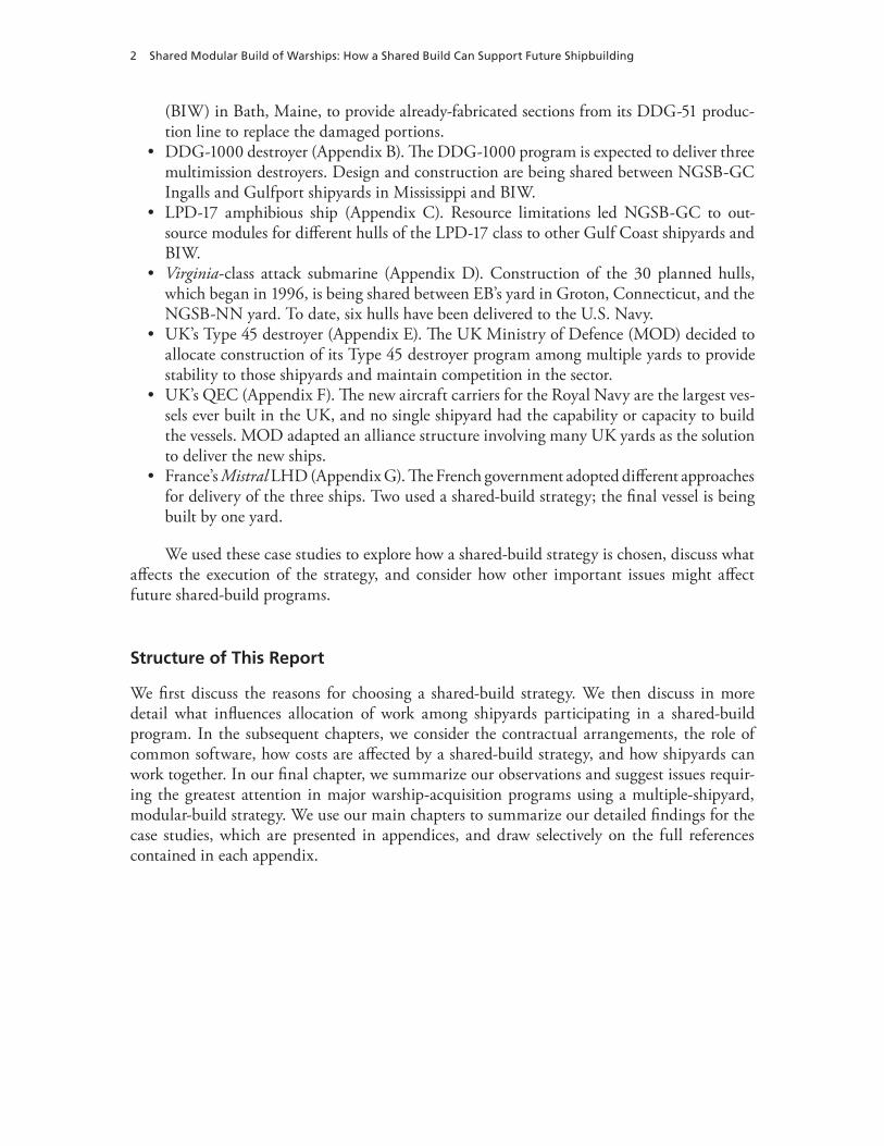
We used a case-study approach, including multiple interviews of subject-matter experts, to generate a list of how cost, benefits, risks, and other issues could affect a decision to follow a shared-build strategy. We conducted field visits to U.S. yards and telephone interviews and open-source literature reviews for European yards. The programs we examined (full details are in the appendices) were as follows:
• DDG-51 destroyer deckhouse (Appendix A). DDG-103 suffered a major electrical fire during construction at the Northrop Grumman Shipbuilding—Gulf Coast (NGSB-GC) yard in Pascagoula, Mississippi. The U.S. Navy contracted with Bath Iron Works
1 More correctly, France calls these bâtiments de projection et de commandement (BPC, or projection and command vessels) with command, helicopter, and docking capabilities. For ease and clarity, we use the more-familiar term LHD.
2 Shared Modular Build of Warships: How a Shared Build Can Support Future Shipbuilding
(BIW) in Bath, Maine, to provide already-fabricated sections from its DDG-51 produc-tion line to replace the damaged portions.
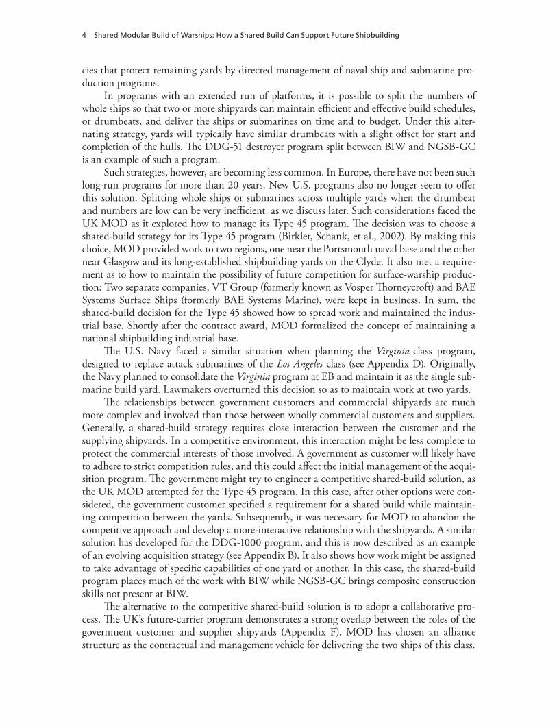
• DDG-1000 destroyer (Appendix B). The DDG-1000 program is expected to deliver three multimission destroyers. Design and construction are being shared between NGSB-GC Ingalls and Gulfport shipyards in Mississippi and BIW.
• LPD-17 amphibious ship (Appendix C). Resource limitations led NGSB-GC to out-source modules for different hulls of the LPD-17 class to other Gulf Coast shipyards and BIW.
• Virginia-class attack submarine (Appendix D). Construction of the 30 planned hulls, which began in 1996, is being shared between EB’s yard in Groton, Connecticut, and the NGSB-NN yard. To date, six hulls have been delivered to the U.S. Navy.
• UK’s Type 45 destroyer (Appendix E). The UK Ministry of Defence (MOD) decided to allocate construction of its Type 45 destroyer program among multiple yards to provide stability to those shipyards and maintain competition in the sector.
• UK’s QEC (Appendix F). The new aircraft carriers for the Royal Navy are the largest ves-sels ever built in the UK, and no single shipyard had the capability or capacity to build the vessels. MOD adapted an alliance structure involving many UK yards as the solution to deliver the new ships.
• France’s Mistral LHD (Appendix G). The French government adopted different approaches for delivery of the three ships. Two used a shared-build strategy; the final vessel is being built by one yard.
We used these case studies to explore how a shared-build strategy is chosen, discuss what affects the execution of the strategy, and consider how other important issues might affect future shared-build programs.
Structure of This Report
We first discuss the reasons for choosing a shared-build strategy. We then discuss in more detail what influences allocation of work among shipyards participating in a shared-build program. In the subsequent chapters, we consider the contractual arrangements, the role of common software, how costs are affected by a shared-build strategy, and how shipyards can work together. In our final chapter, we summarize our observations and suggest issues requir-ing the greatest attention in major warship-acquisition programs using a multiple-shipyard, modular-build strategy. We use our main chapters to summarize our detailed findings for the case studies, which are presented in appendices, and draw selectively on the full references contained in each appendix.

3
CHAPTER TWO
Choosing Shared Build
There are three circumstances under which a multiple-shipyard, modular-build strategy might be adopted:
• A customer, such as a government department, might specify the requirement.• The prime-contracting shipyard might outsource some elements of construction.• During design or construction, an event in the build shipyard might lead to outsourcing
of some of the work.
Generally accepted reasons for shared build include
• providing work to more than one geographic region• maintaining a shipbuilding industrial base • accessing skills available only at different shipyards• overcoming capacity constraints• reducing costs.
Our case studies highlight examples of these decisions and show how the programs devel-oped in each case. In this chapter, we look more closely at how different factors influence the choice of a shared-build strategy.
Specifying Shared Build
Designing and building a warship represents a significant investment of resources. Multiship programs can have a substantial impact on shipyard communities. Not surprisingly, lawmakers might seek to influence where a ship will be designed and built. In recent years, the number of ships and submarines built has decreased under constrained defense budgets and the increas-ing unit cost of modern platforms. The shipbuilding industrial bases in both the United States and Europe have declined as the previous, relatively high demand from national governments has diminished. This has caused consolidation in the sector. In the UK, demand for commer-cial shipbuilding steadily decreased throughout the 20th century, leaving MOD as the major shipbuilding customer (Birkler, Rushworth, et al., 2005). As the size of the Royal Navy dimin-ished, not even future carrier and other early 21st-century programs sufficed to maintain the previous UK shipbuilding industrial base. Similarly, elsewhere in Europe and in the United States, shipbuilding demand has diminished to the point that most governments follow poli-
4 Shared Modular Build of Warships: How a Shared Build Can Support Future Shipbuilding
cies that protect remaining yards by directed management of naval ship and submarine pro-duction programs.
In programs with an extended run of platforms, it is possible to split the numbers of whole ships so that two or more shipyards can maintain efficient and effective build schedules, or drumbeats, and deliver the ships or submarines on time and to budget. Under this alter-nating strategy, yards will typically have similar drumbeats with a slight offset for start and completion of the hulls. The DDG-51 destroyer program split between BIW and NGSB-GC is an example of such a program.
Such strategies, however, are becoming less common. In Europe, there have not been such long-run programs for more than 20 years. New U.S. programs also no longer seem to offer this solution. Splitting whole ships or submarines across multiple yards when the drumbeat and numbers are low can be very inefficient, as we discuss later. Such considerations faced the UK MOD as it explored how to manage its Type 45 program. The decision was to choose a shared-build strategy for its Type 45 program (Birkler, Schank, et al., 2002). By making this choice, MOD provided work to two regions, one near the Portsmouth naval base and the other near Glasgow and its long-established shipbuilding yards on the Clyde. It also met a require-ment as to how to maintain the possibility of future competition for surface-warship produc-tion: Two separate companies, VT Group (formerly known as Vosper Thorneycroft) and BAE Systems Surface Ships (formerly BAE Systems Marine), were kept in business. In sum, the shared-build decision for the Type 45 showed how to spread work and maintained the indus-trial base. Shortly after the contract award, MOD formalized the concept of maintaining a national shipbuilding industrial base.
The U.S. Navy faced a similar situation when planning the Virginia-class program, designed to replace attack submarines of the Los Angeles class (see Appendix D). Originally, the Navy planned to consolidate the Virginia program at EB and maintain it as the single sub-marine build yard. Lawmakers overturned this decision so as to maintain work at two yards.
The relationships between government customers and commercial shipyards are much more complex and involved than those between wholly commercial customers and suppliers. Generally, a shared-build strategy requires close interaction between the customer and the supplying shipyards. In a competitive environment, this interaction might be less complete to protect the commercial interests of those involved. A government as customer will likely have to adhere to strict competition rules, and this could affect the initial management of the acqui-sition program. The government might try to engineer a competitive shared-build solution, as the UK MOD attempted for the Type 45 program. In this case, after other options were con-sidered, the government customer specified a requirement for a shared build while maintain-ing competition between the yards. Subsequently, it was necessary for MOD to abandon the competitive approach and develop a more-interactive relationship with the shipyards. A similar solution has developed for the DDG-1000 program, and this is now described as an example of an evolving acquisition strategy (see Appendix B). It also shows how work might be assigned to take advantage of specific capabilities of one yard or another. In this case, the shared-build program places much of the work with BIW while NGSB-GC brings composite construction skills not present at BIW.
The alternative to the competitive shared-build solution is to adopt a collaborative pro-cess. The UK’s future-carrier program demonstrates a strong overlap between the roles of the government customer and supplier shipyards (Appendix F). MOD has chosen an alliance structure as the contractual and management vehicle for delivering the two ships of this class.

Choosing Shared Build 5
Shared build was required because no single UK shipyard had the capacity to construct these large ships. How the shared-build process works is a decision of the alliance. This example shows how the customer and suppliers can decide on a shared-build strategy for work, indus-trial base, specialty skills, capacity, and cost reasons.
The shared-build decision processes for the DDG-51 deckhouse and LPD-17 were sim-pler. In both these cases, an unforeseen event triggered a decision for a shared build to over-come emerging capacity limitations. In the case of DDG-51, a fire on DDG-103, then under construction, led the U.S. Navy to task BIW with providing replacement sections from its modular-production line so as to alleviate any potential capacity or scheduling constraints at the NGSB-GC Pascagoula yard. In the LPD-17 case, Hurricane Katrina affected NGSB-GC’s capacity, leading it to seek, with Navy approval, to share the build with BIW and other ship-yards in the region.
Construction of the Mistral class (Appendix G) shows a combination of reasons for choosing shared build for the first two ships. The French government determined the delivery schedule, and Direction des Constructions Navales (DCN)1 decided, for capacity reasons, it would be necessary to share the build between the DCN Brest shipyard and the commercial Chantiers de l’Atlantique2 Saint-Nazaire yard. DCN was the prime contractor but also chose to share some construction with the Polish Stocznia Remontowa shipyard to reduce construction costs. The French government allocated the final ship of the class to the Saint-Nazaire yard as part of a financial stimulus package while retaining DCNS as co-contractor with STX France.
In sum, changes in shipbuilding demand—particularly that resulting from diminishing commercial demand at U.S. and European shipyards, as well as military demand for fewer and more-sophisticated ships—has led to shared-build decisions to maintain shipbuilding capacity. Governments have attempted to maintain competition as part of their shared-build strategies with varying degrees of success. Alternatively, it is possible to follow a shared-build strategy that seeks to maintain shipbuilding capacity, sacrificing competitive practices by using collab-orative processes. Our case studies are examples across the spectrum of options and circum-stances that give rise to shared-build programs. In two cases we study, governments sought to spread work by main contractors and so maintain the industrial base (see Table 2.1). In two other cases, governments responded to specific events. In two other cases, governments and the
1 In 2007, DCN changed its name to DCNS. We use DCN in this report for clarity and note here that, more correctly, DCN was responsible for the construction of the Mistral and Tonnerre (2002–2007), and DCNS is responsible for the con-struction of the Dixmude (2009–2012). We use DCNS when discussing this latter ship.2 Chantiers de l’Atlantique became STX France Cruise SA after June 2006. We use Chantiers de l’Atlantique when discuss-ing the Mistral and Tonnerre, the first two ships of the class, and STX France when we mention the construction of the third ship, Dixmude.
Table 2.1Rationales for Shared-Build Cases
DDG-51 Deckhouse DDG-1000 LPD-17 Virginia Class Type 45 QEC Mistral Class
Choice of shared build
Event-constrained
capacity
Access specialist
skills
Event-constrained
capacity
Maintain industrial
base
Maintain industrial
base
Overcome capacity
restrictions
Overcome capacity
restrictions and reduce
costs

6 Shared Modular Build of Warships: How a Shared Build Can Support Future Shipbuilding
shipyards sought to overcome capacity constraints; in one of these, reducing costs was also a primary consideration. Finally, the need to access specialized skills was the primary reason for shared build in one case. In the next chapter, we examine how shared-build decisions can be affected by shipyard capabilities.

7
CHAPTER THREE
Workload-Allocation Strategies
After a decision has been made to pursue a shared-build strategy, the allocation of workload among the shipyards must be designed to meet the overall goals of the program. As shown in the case studies, key drivers for deciding on a workload distribution include capacity con-straints, cost avoidance, and desire to maintain specific skills. Each shipyard has unique capa-bilities, facilities, worker skills, and resources. This chapter details how the workload-allocation strategy in each case was tailored to the specific goals of that program and the unique capabili-ties of the involved shipyards.
In the Virginia-class program, the desire to maintain two yards capable of building nuclear submarines drove the workload allocation. Construction of the nuclear-reactor modules alter-nated between the yards to maintain specialized skills at both. The Navy also alternated final assembly, testing, evaluation, and delivery of the Virginia class between the two yards so that those skills would not atrophy. Beyond these two high-level decisions on how to allocate the work, the rest of the workload allocation was left to the contractors to negotiate.
Besides maintaining those two core skills, the other modules of the Virginia class were allocated to maximize efficiency by taking advantage of each yard’s specialized skills. At the start of construction for the Virginia class, both EB and NGSB-NN had automated machin-ery necessary to efficiently manufacture the ring sections. EB and NGSB-NN chose, for cost-reduction purposes, to manufacture all rings for the Virginia class at EB. Therefore, EB built the parallel midbody and conical frustum pressure hull units. NGSB-NN had previously built complex shapes, so it was assigned the hemiheads and the main ballast tanks. The command-and-control system (CCS) module was assigned to EB because EB had the CCS off-hull assem-bly and test site, a land-based testing platform for the CCS module. The remaining modules were divided to maintain an equal split in the total workload.
The DDG-1000 has a deckhouse made of composite materials: carbon fiber and vinyl ester. NGSB-GC was the only site capable of manufacturing such large composite structures. It was agreed that the best approach was to use the existing composite manufacturing capabil-ity and avoid the need to invest in another composite manufacturing facility in BIW. There-fore, the composite deckhouse was assigned to NGSB-GC. Initially, the remaining modules were to be split between the two yards, in order to maintain capacity at both. Assembly, test-ing, and delivery were also to be alternated between the yards. As the program progressed, the acquisition strategy changed such that NGSB-GC built the deckhouse and the aft peripheral vertical launching system (PVLS) while BIW built the remainder of the ship and was respon-sible for integration of all three DDG-1000 ships.
Throughput limitations can affect the workload distribution of a shared-build program, as demonstrated in the LPD-17 and UK QEC programs. The British QEC program splits

8 Shared Modular Build of Warships: How a Shared Build Can Support Future Shipbuilding
construction among multiple shipyards because no one shipyard can undertake such a large project. The primary objective in the QEC program was cost control, so the workload distribu-tion was designed to minimize cost. In the LPD-17 program, Hurricane Katrina damaged the NGSB-GC yards and limited the availability of labor and material resources, forcing NGSB to outsource work to other contractors, selected for their competency, in order to maintain program schedule.
The British Type 45 program allocated modules to maintain two yards, which meant leveraging existing shipyard skills at the risk of skill atrophy in the other yards. For example, the VT yard in Portsmouth did not receive any of the final assembly, testing, or delivery work for the Type 45 program because the facilities were not capable of handling the final construc-tion of such a large ship. As a consequence, these skills atrophied; for this and other reasons, when building smaller offshore patrol vessels for Trinidad and Tobago, the yards transferred the ships from Portsmouth to Glasgow for completion.1
For the first two ships in the Mistral program, workload distribution was designed to bal-ance the workload capacities of Chantiers de l’Atlantique and DCN and to reduce cost. Chan-tiers and DCN already had ongoing projects occupying space in the yard. Sharing the build of the hulls between the two shipyards allowed construction to begin immediately without waiting for ongoing projects to finish. The modules were distributed to leverage each shipyard’s unique specializations. Chantiers, which typically builds cruise ships, was assigned to build the forward sections of the amphibious assault ship, which contained its large berthing sections. DCN has historically been the shipyard for military ships, so it built the modules that con-tained the internal dock and the complex combat systems. To reduce costs, DCN outsourced some of the steel work to the Polish yard Stocznia Remontowa.
In sum, the workload allocation of a shared-build strategy depends critically on pro-gram goals and unique capabilities of each shipyard (see Table 3.1). Each program must bal-ance competing demands: any requirements of the customer that specified the need for shared build, cost reduction through leveraging of shipyard specializations, and the desire to maintain certain skills across multiple shipyards. These considerations affect acquisition strategies and associated contractual arrangements, as we discuss in the next chapter.
1 At this point, VT Group and BAE Systems Surface Ships were both part of the same joint venture, BVT, and the transfer was, therefore, within the same company.

Wo
rkload
-Allo
cation
Strategies 9
Table 3.1Role of Capability Constraints in Shared-Build Cases
Virginia Class DDG-1000 LPD-17 DDG-51 Deckhouse Type 45 QEC Mistral Class
Capability Constraints
Ring construction; sustain ability
of two yards to integrate and
deliver alternate assembly and
delivery, alternate construction of nuclear reactor, and split rest of modules evenly
Composite deckhouse to
NGSB-GC
Reduced capability (loss of labor and
facilities) after Hurricane Katrina;
outsource some steel work and
minor outfitting to small companies to maintain schedule
Build yard had no spare deckhouse
modules; use deckhouse already being built in BIW
N/A; distribute work to minimize
cost
QEC project too large for single
shipyard; distribute work to minimize
cost
DCN yard could not build whole
ship. Chantiers yard skilled at large-accommodation
construction; living spaces to Chantiers;
combat systems and other military functions to DCN;
some outsourcing of DCN steel work to
Polish yard.


11
CHAPTER FOUR
Contractual Arrangements
Contractual arrangements underpin the acquisition decision to follow a shared-build strategy. Such arrangements will recognize the strengths and limitations of the involved shipyards. Our case studies highlight different types of contractual arrangements.
Alliance Structure
Perhaps the most-complex contractual structure is that of the aircraft carrier alliance (ACA) used by the UK MOD to manage and execute delivery of its future carriers.1 MOD is part of the alliance with the main shipbuilders, system manufacturers, and others. The ACA is an adaptation of alliance structures used in the oil and gas extraction industries, principally when a constructed vessel (typically, a rig) will generate revenue to be shared by alliance members. The QEC will not generate revenue, so MOD must provide all funding and profit opportunity. Still, there are a number of claimed benefits to the ACA structure, including collective owner-ship of risk and reward. All ACA members share equally any profit or (capped) loss. Two levels of contract make the ACA work: An alliance agreement establishes the arrangement, governs management processes, and lays out the behavior of members; and work contracts, more typi-cal to standard contracts, describe the scope of work. Other ACA features include
• commitment to trust, collaboration, innovation, and mutual support• collective ownership of risks and reward• full “open-book” accounting• decisions made on best-for-the-ACA basis• culture of no fault, no blame, and no dispute.2
Prime and Subcontractor Structures
A traditional contract has a prime or lead supplier under contract to the customer. The prime might then subcontract with selected suppliers. There are a number of variations on the prime-subcontractor structure. Perhaps the most straightforward is that in which the prime contrac-tor selects its own suppliers and makes the necessary contractual arrangements without any
1 Australia is also using an alliance contract for its current Air Warfare Destroyer program.2 We discuss these features, particularly the ACA “culture,” in more detail in Appendix F.

12 Shared Modular Build of Warships: How a Shared Build Can Support Future Shipbuilding
direct involvement from the government customer. The LPD-17 and Mistral programs are in this category: The prime contractors in each selected supporting shipyards to assist them via a subcontracting agreement. As discussed earlier, for NGSB-GC in the LPD-17 program, this was the consequence of a loss of capacity following Hurricane Katrina. In the Mistral program, DCN subcontracted with Chantiers to overcome capacity constraints and with the Polish Stocznia Remontowa yard to take advantage of lower manpower costs.
A collaborative contractual arrangement is often recognized as a teaming structure. Typi-cally, teams compete for a contract having prearranged the contractual structures, work share, and profit arrangements. The contractual arrangement for delivery of the Virginia class is a good example of a teaming arrangement with EB as the prime contractor and NGSB-NN as the subcontractor. This contract, which we also discuss later, allowed for open bookkeeping between the shipyards and an equal split of any profit. This resulted in a great deal of trust between the management of each yard, as well as motivation to help the other improve perfor-mance.3 The yards might choose to remain in the same teaming arrangement for future U.S. Navy submarine programs if they are not asked to compete for the work against each other.
The UK’s Type 45 program passed through a number of contractual structures before MOD decided to follow a shared-build strategy with a directed prime and subcontractor arrangement. Initially, there was a teaming arrangement between the then–BAE Systems Marine and VT Group shipyards as strategic partners, each subcontracted to BAE Systems as the prime contract office (PCO).4 This arrangement did not work, as we describe in more detail in Appendix E, and it disbanded until MOD decided to allocate modules across yards and force a shared-build approach. The yards saw each other as competitors, however, and therefore had no open-book accounting, even when they were together in the ACA to build the QEC carriers. Rather, they introduced internal controls to protect information not associated with the QEC program.
Government-to-Contractor-Only Structure
The final variation of contractual structure is that of a main yard under contract to the U.S. Navy with the shared-build work undertaken in a second yard under a separate contract to the U.S. Navy (current DDG-1000 process). In the DDG-1000 program, there are four primes: BIW, NGSB, Raytheon, and BAE. The Navy supplies the modules to the main yard as government-furnished equipment (GFE) and assumes the cost risk of any issues that arise during the integration of the GFE. As we describe in the case studies and in a later chapter, the yards must work together to make sure that the supplied modules fit and are equipped with the expected fittings.
In sum, three types of contractual arrangements are common in shared-work structures (see Table 4.1). Alliance structures have partners working together equally for any resulting profit or loss, with an agreement establishing obligations and responsibilities of each. Shared-work structures are also possible under traditional prime and subcontractor structures, in which partners might share equally or be designated beforehand. Finally, the government might wish
3 The UK MOD studied this arrangement before deciding on the alliance structure for its QEC program.4 As we explain in more detail in Appendix E, BAE Systems Marine was a subsidiary of BAE Systems. MOD required BAE Systems to introduce complex controls to ensure that it could act as a prime contractor to BAE Systems Marine.

Contractual Arrangements 13
to contract with each partner separately, providing the module or product of other yards as GFE to the assembly yard. These different contractual arrangements can also require special approaches to innovative technologies and other issues. We turn to some of these next.
Table 4.1Contractual Arrangements in Shared-Build Cases
Virginia Class DDG-1000 LPD-17DDG-51
Deckhouse Type 45 QEC Mistral Class
Contractual arrangements
Intimate teaming,
prime-sub
GFE Prime-sub GFE Prime-sub Alliance Prime-sub


15
CHAPTER FIVE
Design Software and Information Technology Systems
Modern shipbuilding is a data-intensive activity that leverages computation and digital data-bases to increase efficiency. From detailed design drawings to parts databases to quality con-trol, information technology (IT) plays a critical role. When multiple shipyards collaborate to share build on a hull, data exchange is crucial, and thus the ease with which shipyard IT systems can be linked is of critical importance. For example, the DDG-1000 program suf-fered many delays because of difficulties sharing and operating the complex software needed for detailed design (GAO, 2008). This section discusses IT approaches undertaken and lessons learned for shared-build programs.
The IT systems at a shipyard encompass all aspects of the build, from parts databases to design tools to configuration management to execution systems to business management systems. The level at which those IT systems need to be linked across yards depends on the intensity of the shared-build relationship. For complex programs, such as the Virginia class, in which both yards produce half the ship, data sharing is key. The complexity of the Type 45 and QEC programs also requires extensive data sharing. For more-unequal relationships, such as NGSB outsourcing steel work for the LPD-17 program, only paper drawings were shared.
Ideally, software should be common across yards to reduce the cost and risk of translating data between systems. Nevertheless, different yards might have different systems that would be expensive or infeasible to change. Particularly in such yards as NGSB-NN that manage multiple construction projects, changing systems just for one project is a difficult proposition.
For the Virginia class, EB and NGSB-NN recognized that dramatically changing IT sys-tems was not feasible, so only a few key systems were made common between the yards:
• construction-drawing index• change-order master for adjudicating drawing revisions and engineering reports• certification files• shipyard discrepancy-control database• test index• work breakdown structure for management and control• work-area designation/space map• work package numbering process• master part-number catalog.
More than 60 other processes and systems were linked or developed to allow transfer of information between the existing systems of the two shipbuilders, including systems that cover

16 Shared Modular Build of Warships: How a Shared Build Can Support Future Shipbuilding
the design data, welding, material, planning, quality, engineering, and manufacturing. Gener-ally, the software was integrated successfully, but certainly at a cost.
The need for a common design suite depends on the level of collaboration in the design. Virginia-class program data sharing was eased by EB’s having control of the design. NGSB-NN needed to translate some of the drawings into its terminology, but the bulk of the design was under EB’s purview.
In the original DDG-1000 program acquisition process, in which design was shared evenly between the BIW and NGSB-GC, both yards used the same design software and a common data center. While this is an ideal situation, and certainly considered necessary by the participants of the DDG-1000 program, there were still significant challenges, such as delay and bandwidth issues in accessing data. This led to delays in the design effort until better IT infrastructure was installed (GAO, 2008).
The detailed design for the ongoing UK QEC program was shared between teams at five different locations. A web-based shared data environment tool was developed to facilitate access, with the goal of minimizing interference with each yard’s existing production processes and tools. Similar to the DDG-1000 program, a common data storage center was developed. The UK Type 45 destroyer program also had a shared data environment developed by the prime contractor, BAE Systems. The Type 45 program’s shared data environment, however, could not contain information requiring handling as confidential or at a higher level of secu-rity; and technical design data were limited to graphical representations. The actual computer-aided design (CAD) files used for the design were not shared through this environment (Tang and Molas-Gillart, 2009).
As the case studies show, shipyards prefer to retain their existing systems when engaging in a shared-build strategy (see Table 5.1). The need for common IT systems is modulated by the required degree of interaction between the shipyards. If the yards are sharing the build of com-plex modules, common systems are likely required for some critical project-management func-tions. If the yards are sharing the design effort, then having a common software system and data storage center is also important, and the supporting IT infrastructure must be developed. As the DDG-1000 case study shows, there are no insurmountable technical barriers to build-ing a successful integrated, cross-yard IT infrastructure for a shared-build strategy, and yards embarking on such an endeavor will likely need to consider the issues discussed in this chapter.
Table 5.1Design Issues in Shared-Build Cases
Virginia Class DDG-1000 LPD-17DDG-51
Deckhouse Type 45 QEC Mistral Class
Design software and IT
Shared design system,
separate business systems
Shared design systems
N/A N/A Separate design
systems, limited data
sharing
Shared data warehouse,
two separate design systems
Separate

17
CHAPTER SIX
Cost Implications
Cost control is a perennial focus of any shipbuilding program. Various options for distributing work among the shipyards carry differing costs. This chapter examines the key differences of costs for three main procurement options: building all the hulls in one shipyard (single build), alternating the hulls between two shipyards (alternating build), and sharing modules between two shipyards (shared build). Key determinants of costs include labor, material, and facility costs. If modules are shared between two shipyards, additional transportation and collabora-tion costs are incurred. While a full accounting of the cost differences is beyond the scope of this study, we review here basic elements of costs for various procurement options.1
Learning-Curve Effects
As shipbuilders build a new class of ships, they learn from hull to hull and develop the most-efficient methods, leading to reductions in the work required for subsequent hulls. Empirical studies have shown that such learning curves take a log-linear form. For example, a 90-percent learning curve means that a doubling in the workload leads to 90-percent work requirement, with the second unit requiring 90 percent of the work of the first unit, and the fourth unit requiring 90 percent of the work of the second unit. Mathematically, this means that the nth hull requires the work w w nn
b= 12log , where b is the learning rate.2
Learning’s critical dependence on the number of repetitions can lead to differences in learning among the three strategies. In the alternating-build strategy, in which each shipyard builds half of the hulls in a class, each shipyard proceeds on the learning curve at half the rate of the single-shipyard build.3 For example, the eighth hull of a class would be only the fourth built by one of the shipyards. Thus, there might be a cost disadvantage to the alternating-build strategy.
1 Some cost information was provided for the individual case studies, as detailed in the appendices, but not the complete accounting of costs necessary for comparative analysis.2 This is an empirical relationship derived from actual program data and a theoretical formula. The programs from which the learning rates are estimated have mostly sequential construction. Where the time lapse between ships or modules is extremely long, knowledge would likely be lost. The relationship used in this chapter to assess learning rate assumes a time lapse typical of recent programs.3 This assumes that the lessons learned by the first shipyard are not transferred to the second shipyard, either because they are not shared or because they not applicable to the other shipyard’s build methodology. This section treats more-complicated cases in which learning is shared.

18 Shared Modular Build of Warships: How a Shared Build Can Support Future Shipbuilding
The theoretical learning-curve effect of alternating hulls between shipyards is illustrated in Figure 6.1. This shows, for a given number of hulls built, the increase in man-hours of an alternating-build strategy over a single-build strategy. For example, at a 90-percent learning curve, splitting 12 hulls evenly between two shipyards would require about 9 percent more man-hours than allocating all 12 hulls to a single shipyard.
Note that these theoretical curves assume two homogeneous yards, an even build split, no shared learning between the yards, and no competition effects on the yards. If the two yards had different learning curves, the percentage increase in man-hours would be a combination of the curves illustrated in Figure 6.1.4
It is also possible that lessons learned from one yard might be shared with another yard. However, not all learning is transferable: The increased efficiency of individual skilled work-ers, for example, cannot be transferred. Nevertheless, process improvements or design changes might be transferable between shipyards. A profit-sharing incentive contract, similar to the Virginia-class contract, coupled with an alternating-build strategy, can encourage sharing of learning.
To model the effects of shared lessons, we introduce a shared-learning factor. A shared-learning factor of 30 percent, for example, means that, when the first yard is building the first hull, 30 percent of the lessons learned transfer to the second yard. In other words, when the second yard is building the second hull, it is as if the yard had already built 30 percent of a ship. The most-ideal situation, with 100-percent shared learning, means that both shipyards are traveling the same learning curve together and, thus, recover the efficiency of a single-shipyard build.
4 For more detail on how the distribution affects the cost increase, see Birkler et al., 2002.
Figure 6.1Learning-Curve Effect of Alternating Hulls Between Shipyards
RAND TR852-6.1
0
2
4
6
8
10
12
14
16
18
Total number of hull units
Incr
ease
in m
an-h
ou
rs (
%)
85%
90%
95%
100%
0 2 4 6 8 10 12 14 16 18 20 22 24 26 28 30

Cost Implications 19
Figure 6.2 illustrates the theoretical effect of different shared-learning factors on the cost premium of an alternating-build strategy (using the 90-percent learning curve as the baseline). If, for a 12-hull build split evenly between two shipyards, 40 percent of the learning were to be transferable between shipyards, then the cost premium of an alternating-build strategy would diminish to about 4.5 percent (recall that an even split of 12 hulls with no shared learning yields a 9-percent cost increase).5 In practice, because it is difficult to separate the learning that results from increased worker skill to that of process improvements, empirically estimating the shared-learning factor is difficult. The prospect of future competition might also discourage any sharing.
Other costs of using two shipyards can include the fixed costs of operating the shipyard, reduced economies of scale in material procurement if the shipyards use different vendors, and duplicative government oversight. These costs will vary by program and are not estimated in this theoretical analysis.
If one were—say, for political or capacity reasons—forced to use two shipyards for con-struction, there would be many methods to compensate for adverse learning-curve effects. One approach, already explored, would be to encourage the sharing of lessons learned between the shipyards. A second would be to distribute blocks or sections between shipyards. In this shared-build scenario, each shipyard would build the entire set of blocks for the class and thereby drive down the learning curve for block fabrication at the same rate as on a single-shipyard build. Instead of a single shipyard building all 12 hulls, two shipyards would each build 12 halves of the hull. This strategy would have the equivalent optimal learning curve as the single-build strategy (less any learning related to the integration and testing of the assembled blocks).
5 This assumes that the hulls are sequenced such that lessons learned on the first hull apply to all successive hulls.
Figure 6.2Cost Premiums Associated with Shared Learning in an Alternating-Build Strategy (assuming an underlying 90-percent learning curve)
0% shared learning
20% shared learning
40% shared learning
60% shared learning
80% shared learning
100% shared learning
RAND TR852-6.2
0
2
4
6
8
10
12
0 2 4 6 8 10 12 14 16 18 20 22 24 26 28 30
Total number of hull units
Incr
ease
in m
an-h
ou
rs (
%)

20 Shared Modular Build of Warships: How a Shared Build Can Support Future Shipbuilding
A shared-build strategy can also reduce costs by shifting work of specific blocks to ship-yards that excel at building them. For example, as we noted earlier, in the French Mistral-class program, the fore section of the ship and its living quarters was assigned to Chantiers, a commercial shipbuilder with experience building cruise ships. By contrast, in an alternating-build strategy, each shipyard builds the entire hull, with no opportunity to distribute special-ized work.
Sharing of information across yards in a shared-build strategy is also critical for learning. The Virginia-class program has continually made changes to the work-share agreement or the collaboration process to increase efficiency.
Shipyards in a shared-build strategy have other costs not incurred in an alternating-build strategy. These include the cost of transporting blocks between shipyards, of weatherproofing blocks for transportation, of additional facilities for moving large blocks, and of IT architec-ture to facilitate data transfer. Table 6.1 summarizes the types of cost differences among the three build strategies. Table 6.2 summarizes the cost implications of each of our shared-build case studies.6
Table 6.1Build-Strategy Cost Characteristics
Build Strategy Possible Cost Characteristics
Single build Most optimal (where other constraints allow)
Alternating build Suboptimal learning curveAdditional fixed shipyard costsAdditional government-oversight costsLower economies of scale in material buys
Shared build Optimal learning curveEfficiency gains from leveraging prior module specializationsAdditional fixed shipyard costsAdditional government-oversight costsTransportation costsAdditional facility costs for block handlingAdditional IT infrastructure costs
6 A more-detailed analysis of each program was beyond the scope of this project. See Birkler et al., 2002, for an example of a more-rigorous analysis of different procurement options (which, in that case, was for the UK’s Type 45 destroyer).

Co
st Imp
lication
s 21
Table 6.2Cost Implications of Shared-Build Cases
Virginia Class DDG-1000 LPD-17 DDG-51 Deckhouse Type 45 QEC Mistral Class
Cost implications Transportation costs, IT
infrastructure costs, additional
design-translation cost
Transportation costs, IT
infrastructure costs for common data
systems
Transportation costs
Transportation costs
Transportation costs
Transportation costs, IT
infrastructure costs,
infrastructure-modification costs
Transportation costs


23
CHAPTER SEVEN
Shipyard Collaboration During Shared Build
In a shared-build effort, collaboration between the shipyards can be critical. The amount of collaboration required tends to depend on the complexity of the shared interface between disparate modules. Communication plays a larger role in complex programs, such as that of the Virginia class, with multiple levels of shared build (including modules built by EB to be assembled in NGSB-NN containing submodules originating at NGSB-NN). The DDG-1000 and Mistral-class programs have simpler module interfaces, and these programs will likely not require as much collaboration; modules are self-contained and then joined. This chapter examines shipyard collaboration in shared-build programs and discusses various collaboration methods that programs have implemented.
There are no technical barriers to proper module assembly. Most modern shipyards already build hulls in modules and have sophisticated tools for quality assurance. Most ship-yards reported during our visits that the quality-assurance issues with shared build are no greater than those encountered during modular construction within a single shipyard. The key challenge lies in communicating exactly what is in the modules, particularly at the inter-faces, and how the modules were built. Tackling this involves several steps, starting with a well-defined work-share agreement that details the work assignments, including the amount of outfitting before delivery. This level of data transparency, evident in both the Virginia-class and DDG-1000 programs, reduces schedule or cost risk during assembly. In the DDG-1000 case, the close collaboration and inspection between BIW and BAE identified and resolved many of the interface issues early. The early sharing of prototypes between BIW and NGSB to test the interfaces also illuminated issues that would have been far more difficult to resolve later. In all the programs we reviewed, personnel from the receiving yard regularly visited the other yard to understand what was being built.
Collaborating with smaller companies might require particular attention. For some hulls of the LPD-17 program, steel work was outsourced to various manufacturers. NGSB-GC deployed local accuracy-control teams to resolve some early quality issues and received weekly progress reports and frequently inspected outsourced units. NGSB-GC also learned that the subcontractor must have the experience needed to satisfactorily execute the work. Other small companies also lacked experience managing projects of the contracted size or faced unexpected resource problems. Overall, as NGSB-GC personnel explained in interviews, collaborating with smaller contractors understandably requires additional attention and support.
The key barrier to sharing and innovating for more-efficient build processes is the pros-pect of future competition. Nevertheless, as the Virginia-class program demonstrates, with the proper environment and incentives, even two shipyards that, like EB and NGSB-NN, were former competitors (in their case, for submarine programs) can develop a strong working rela-

24 Shared Modular Build of Warships: How a Shared Build Can Support Future Shipbuilding
tionship. When the teaming arrangement was made, management at both EB and NGSB-NN made successful collaboration a top priority, setting the tone for the relationship. Early on, an even split of the workload and profit put the two companies at parity, even though, contractu-ally, EB was the prime and NGSB-NN the subcontractor. The complexity of shared build also required close sharing of processes for success. The specter of future competition was ignored in favor of making the immediate program a success. In part, the challenge was easier because EB built only submarines, so there would be no competition in other hull types, such as surface ships. The teaming arrangement, splitting the total profit evenly, encouraged the sharing of les-sons and process innovations. Decisions that had implications for both yards were often made through a business case analysis, with a focus on cost reduction. The arrangement was far from perfect but worked to reduce cost and successfully build the Virginia class.
Also, in the Virginia class, the shipyards’ ability to move large blocks initially limited the level of innovation. As a product of collaboration, EB and NGSB-NN improved processes so as to consolidate the outfitting of the ten separate modules into four supermodules—reducing the need for transportation of modules between yards. Consolidation increased the efficiency of the build, but there were limits to it. Supermodules were capped at a maximum 1,450 tons, the most weight the transportation barge could support. Program managers stated that more transportation capacity would have yielded more consolidation in the outfitting.
Other ongoing construction can also affect the feasibility of collaboration. NGSB-NN not only builds modules for the Virginia class but also builds and refuels nuclear-powered air-craft carriers and performs maintenance on submarines and aircraft carriers. Both NGSB-GC and BIW build DDG-51 hulls. In some cases, other construction programs can be an advan-tage. For example, they can support a larger workforce that can be moved between projects, providing a surge capability if critical construction falls behind for any reason. Yet, other construction programs can also hinder the integration of work practices between shipyards in a shared-build project. For the Virginia class, NGSB-NN is able to move workers between submarine and carrier construction, particularly in common skills, such as piping. This made aligning piping work practices with EB difficult because that would have adversely affected NGSB-NN aircraft-carrier construction processes. Ultimately, NGSB-NN and EB agreed that different piping work practices could be overcome without affecting the overall build efficiency. In integrating other systems with EB, such as IT architecture and design software, NGSB-NN had to balance its interest in lowering cost on the Virginia program with the impact that such initiatives would have on the cost and schedule of its other Navy projects.
In conclusion, the amount of required collaboration between the shipyards for a suc-cessful program depends on the complexity of the shared build. Although there are no hard technical obstacles to collaboration, often several factors can limit the level of collaboration between the yards. These include the prospect of future competition, capacity constraints at smaller subcontractors, transportation ability for large blocks, and competing demands within a shipyard. Table 7.1 summarizes levels of collaboration in our case studies.

Ship
yard C
ollab
oratio
n D
urin
g Sh
ared B
uild
25
Table 7.1Shipyard Collaboration in Shared-Build Cases
Virginia Class DDG-1000 LPD-17 DDG-51 Deckhouse Type 45 QEC Mistral Class
Shipyard collaboration
Extensive collaboration at all levels of
management and production
Integration yard QA personnel at
supply yards
Minimal collaboration,
some QA oversight
Some QA collaboration
Integration-yard QA personnel at
supply yards
Fully integrated program
management, integration-yard QA personnel at
supply yard
Minimal collaboration, some
QA oversight
NOTE: QA = quality assurance.


27
CHAPTER EIGHT
Comments
There are no irresolvable technical obstacles to a shared-build strategy. Most modern shipyards have the capability to build and integrate modules, whether those modules originate at that shipyard or at another. Some yards might need to modify their facilities, however, to handle large blocks, rather than completed vessels, at the waterfront. Our case studies indicate poten-tial risks to success of a shared-build strategy and show potential variations to overall program costs. We summarize the characteristics of the case studies in Table 8.1.
Although shared build can work, it might not always deliver the outcome expected when the decision to adopt it is first made. For example, it might not maintain skills at all shipyards equally, which was the hoped-for outcome of MOD’s decision for a shared-build strategy in the Type 45 program. Modular build does not require each participating shipyard to main-tain all skills. While the former VT Group shipyard in Portsmouth was able to efficiently and effectively build modules for the Type 45 program, the retained modular skills, in turn, made it more difficult for the yard to complete its own smaller patrol vessels in follow-on programs; thus, the testing and commissioning was undertaken at another yard. The Virginia-class pro-gram shows how, in different circumstances, a shared-build program can help maintain ship-building skills at multiple shipyards. There are likely to be extra costs associated with such duplicated capability if hull numbers and drumbeat are not carefully managed.
Further, it is not clear that shared build is an effective means to preserve competition. This is because success in a shared-build program, particularly for complex vessels, requires the cooperating shipyards to set aside any competitive tendencies and help each other to the overall benefit of the program. The prospect of future competition will inhibit such a process, as was seen in the early stages of the UK’s Type 45 program. Conversely, shipyards in a successful shared-build program seem keen to remain in such a structure for subsequent work. The team-ing arrangement delivering the Virginia-class submarines reinforces this observation; the UK’s alliance structure for delivering the future carriers evolved from multiple shipyards via a joint venture to a single shipyard.
We conclude that the government (or Navy) needs to decide what it wants from a shared-build strategy before embarking on it. Once a decision is made, the program manager must then monitor and manage the program to ensure that it delivers the required outcome, as well as the vessels called for in the program.
We next consider the risks to successful completion of a shared-build strategy and then discuss the necessary costs. In separating risk and cost, we recognize that failure to mitigate risk can lead to extra costs, but we see these as avoidable costs rather than the necessary costs, such as those for module transportation between yards.

28 Shared
Mo
du
lar Bu
ild o
f Warsh
ips: H
ow
a Shared
Bu
ild C
an Su
pp
ort Fu
ture Sh
ipb
uild
ing
Table 8.1Characteristics of Shared-Build Programs Studied
Characteristic Virginia Class DDG-1000 LPD-17 DDG-51 Deckhouse Type 45 QEC Mistral Class
Number of units 30 3 9 1 6 2 3
Choice of shared build
Maintain industrial base
Access specialist skills
Event-constrained capacity
Event-constrained capacity
Maintain industrial base
Overcome capacity restrictions
Overcome capacity restrictions and
reduce costs
Capability constraints
Ring construction; sustain ability
of two yards to integrate and
deliver alternate assembly and
delivery, alternate construction of nuclear reactor, and split rest of modules evenly
Composite deckhouse to
NGSB-GC; rest to BIW
Reduced capability (loss of labor and
facilities) after Hurricane Katrina;
outsource some steel work and
minor outfitting to small companies
Build yard had no spare deckhouse
modules; use deckhouse already being built in BIW
N/A; distribute work to minimize
cost
QEC project too large for single
shipyard; distribute work to minimize
cost
DCN yard could not build whole ship.
Chantiers yard was skilled at large-accommodation
construction: living spaces to Chantiers;
combat systems and other military functions to DCN;
some outsourcing of DCN steel work to
Polish yard
Contractual arrangements
Intimate teaming, prime-sub
GFE Prime-sub GFE Prime-sub Alliance Prime-sub
Design software and IT
Shared design system, separate business systems
Shared design systems
N/A N/A Separate design systems
Shared data warehouse, two separate design
systems
Separate
Cost implications Transportation costs; IT
infrastructure costs; additional
design-translation cost
Transportation costs; IT
infrastructure costs for common data
systems
Transportation costs
Transportation costs
Transportation costs
Transportation costs; IT
infrastructure costs;
infrastructure-modification costs
Transportation costs
Shipyard collaboration
Extensive collaboration at all levels of
management and production
Integration-yard QA personnel at
supply yards
Minimal collaboration
Some collaboration Integration-yard QA personnel at
supply yard
Fully integrated program
management; integration-yard QA personnel at
supply yard
None

Comments 29
Risks to Shared-Build Programs
Although our case studies do not allow direct comparison between different programs, we group our findings into four areas in which risk reduction is important. Reducing risk will give greater assurance that a program can deliver the required vessels, that they will be deliv-ered on time, that they will be of the required quality, and that the program will meet its cost targets. Our four risk-reduction areas are motivating cooperation, design completion, design and design-to-production organization, and aligning production practices and schedules. A failure in the earlier stages of this progression is more likely to be catastrophic to the program than failure later on. The importance of these risk-reduction areas increases with the complex-ity of the modular-build process, which, in turn, is linked to the complexity of the vessel to be built. In other words, shared-build risks are likely much higher for more-complex vessels than traditional-build risks for such vessels.
Motivating Cooperation
Contractual obligations and financial remuneration are only part of the process for successfully motivating shipyards to cooperate. Although our Mistral-class and LPD-17–class studies show the least additional cooperation effort beyond the contract specification, these were the least complicated of the warships we studied and therefore required the least cooperation. At the heart of cooperation is the trust between the yards at almost every level of management and production. Trust can be improved with open-book accounting and fair division of profit (or loss). The prospect of future competition might impede open-book accounting and the degree of trust that can be achieved. Yards are unlikely to share best practices if there are proprietary concerns. The government (or Navy) needs to encourage cooperation between reticent ship-yards; this might be done through contracting structures, workload allocation, or any other lever available to government. The UK’s QEC alliance and the Virginia teaming arrangements are good examples of how to motivate cooperation.
Design Completion
A modular-build process requires greater detailed design completion before construction starts than traditional “stick build” shipbuilding. Detailed design is a key step in mitigating rework requirements by allowing better quality control and ensuring accurate and timely stock deliv-ery to the production process. This becomes even more important when those modules are to be built at two or more locations. In particular, the design at the module interfaces needs to be fully understood and, therefore, practically complete for modules to integrate easily.
Design and Design-to-Production Organization
Closely linked to the ability to complete the design, producing complex modules that are easy to integrate requires the yards to reach a detailed and common understanding of what affects module interfaces. This includes the part manifest and other aspects of production linked to detailed design. The involved yards must detail the build assignments down to the piece-part level at the interfaces. To achieve such commonality requires either common design software or compatible design software linked to a common design data bank. For complex designs, IT systems and the supporting software can become very complex and susceptible to instability.

30 Shared Modular Build of Warships: How a Shared Build Can Support Future Shipbuilding
Aligning Production Practices and Schedules
Modular construction within a single yard is easily aligned, but that between two yards, par-ticularly those that have not worked together or that are at different stages of modernization, can be difficult to achieve. Aligning production practices requires each yard, and, in particular, the integration yard, to understand differences in production processes. This is of vital impor-tance at the interfaces of complex, outfitted modules. Many of the integration yards in our case studies sent their own personnel to implement additional quality-assurance processes at the supplying yard. Aligning the production schedules also requires pacing module construction to the same completion drumbeat. If the planned work on a block in one yard becomes late, it might be necessary to deliver that block unfinished to the other shipyard. It might then be finished by a deployed team from the originating yard or by labor at the receiving yard. Such an arrangement will affect subcontractors and suppliers and likely add further to costs. Alter-natively, the block could be delayed until complete, with potentially serious scheduling effects on the production plan at the receiving yard.
Costs of Shared-Build Programs
The risks discussed in the preceding section could lead to increased program costs apportioned according to the shared management structure and contractual requirements. There is a fur-ther set of costs linked directly to the shared-build decision. The key shared-build costs we identified in our case studies are as follows:
• Demarcation of block completion. Shared build places a requirement for the supplying and receiving yards to agree on the completeness or otherwise of the supplied blocks. A receiving yard will want as much notice as possible if there are to be changes to either the expected completion state of the block or to the delivery schedule. To mitigate the impact of such events and to reduce overall program costs, both yards will want to monitor block completion, assess progress, and determine whether revisions to the delivery schedule will be needed. Such steps will add costs.
• Design for transportation. Modular build places specific structural integrity and stabil-ity requirements on the designers so the modules can be moved within the yard. Where there is a requirement for open-ocean transport of these modules, as is the case in most of our case studies, the structural and stability requirements are more demanding. Any such requirements will increase the design and production costs.
• Transportation. Moving completed modules from the supplying yard to the integration yard will add cost to the program. In some circumstances, such as those in which shared build is not planned but becomes necessary because of external events, these costs can be significant. One option to reduce costs is for the shared-build yards to own the transpor-tation barge. This is the practice in the Virginia program, in which EB already owned a suitable barge. The QEC program followed a different solution, placing a single contract with a specialist shipping-and-transportation company for moving all QEC modules. There will be incidental costs for each move associated with additional work to the mod-ules and possibly the barges to allow the module to be adequately secured.

Comments 31
• IT infrastructure. Especially in shipyards with very different IT systems, linking those systems or adopting a uniform system is a necessary cost. At additional cost, design teams are also needed at both yards to understand and implement the common design.
• Resource management. Successful modern shipyards carefully manage their resources, such as manpower and facilities, to maximize efficiency. Block build places particular demands on build manning with, for example, a block move coinciding with peak man-ning. In shared build, the block leaves the shipyard, so there is limited scope for a smooth ramp-up and -down of the workforce. Equally, in the receiving yard, the block would be ready to absorb peak manning, and this is difficult to achieve instantaneously. The facili-ties in the yards are similarly affected. This effect can be mitigated by other work in the yards. Shared build might require specific investment in delivering-yard and receiving-yard facilities to allow transfer of the modules.
The potential benefits to the cost of a program that follows a shared-build strategy include the following:
• Maximizing the learning curve. A shared-build strategy, in which the same modules are fabricated at the same yard, for a relatively small number of hulls, can offer more opportu-nities to derive learning-curve efficiencies than an alternating, whole-hull schedule would offer.
• Cross-yard learning. In some circumstances, the sharing of lessons learned and the collec-tive innovation of more-efficient processes can reduce cost.
• Outsourcing benefits. Assigning modules to shipyards with a specific specialization or lower manpower costs can lower the costs of an overall program.


33
APPENDIX A
DDG-51 Deckhouse Case Study
The ships of the Arleigh Burke class of guided-missile destroyers are the workhorses of the U.S. Navy. At least 63 hulls are planned. On May 20, 2006, the DDG-103 (USS Truxtun) suffered a major electrical fire during construction at the NGSB-GC yard in Pascagoula, Mississippi. The fire destroyed two levels of the deckhouse (Figure A.1). Following this fire, the Navy con-tracted with BIW to provide already-fabricated sections from its DDG-51 production line to replace the damaged portions.
Design and Construction Plan
BIW provided seven units from its existing construction on DDG-108 and DDG-106. These deckhouse units were already complete or nearing completion when the fire occurred. Units 4220, 4230, and 4240 were joined together into a single unit before transfer to NGSB-GC (Figure A.2). These modules were constructed with standard accuracy-control and quality-assurance procedures, complete to the end of the preoutfit 1 stage, and therefore ready for blasting and painting. BIW also shipped numerous outfit items that were already completed
Figure A.1View of the DDG-103 Deckhouse After an Electrical Fire
SOURCE: Willshaw (2009). Used with permission.RAND TR852-A.1

34 Shared Modular Build of Warships: How a Shared Build Can Support Future Shipbuilding
for the deckhouse but could not be installed until later phases in the construction. All the BIW materials were delivered as GFE.
Shipyard Collaboration Methods
BIW and NGSB-GC collaborated to ensure shared understanding of the configuration and measurement of the BIW modules. There were no major interface problems, but many small differences in BIW’s and NGSB-GC’s build and design practices had to be resolved. An NGSB team of experts traveled to BIW to help communicate and mitigate concerns and risks at both yards. According to both shipyards, the key was communication not only regarding the engineering-interface control drawings but also about the nuances of construction. For exam-ple, many of the ventilation ducts, wire-way hangars, and ventilation hangars were slightly dif-ferent between BIW and NGSB-GC. NGSB-GC also had to understand what was included in BIW’s construction when integrating the pieces with the rest of the ship.
Transportation Arrangements
Transportation for these modules, with a total load out of 2,800 tons, was arranged by NGSB and the U.S. Navy. The completed units were transported to NGSB-GC shipyard using one barge; the location of the yards is shown in Figure A.3. The barge, which was contracted by NGSB-GC, was commercially available but required about 50 hours of prestaging to accom-modate the DDG-51 units. Various parts to be attached to the deckhouse at later phases of construction were shipped separately by truck. NGSB-GC noted that, because it had prior experience towing large pieces, transporting the modules was not a major issue.
Figure A.2DDG-51 Sections
SOURCE: Kenyon (2009, slide 3). Used with permission. RAND TR852-A.2
Existing DDG103 units
Units fromDDG 108
Units fromDDG 106

DDG-51 Deckhouse Case Study 35
An important lesson from this shared-build process is the need to define the scope of work at the lowest level possible, ensuring that each shipyard knows what to expect and what is required. This requires constant interactions between shipyard representatives who know the design and construction of the end product. Transportation issues must be addressed early to understand the sizes of the modules that can be moved, transported, and accepted by the final shipyard. Modifications to facilities or the sizes of the modules might be required.
Figure A.3Shipyards Involved in the Construction of DDG-103
RAND TR852-A.3
ME
NGSB-GCPascagoula
BIW


37
APPENDIX B
DDG-1000 Case Study
The DDG-1000 ships of the Zumwalt class are 15,000-ton multimission destroyers for naval surface fire support and operations in littoral waters. Originally envisioned as a class of 32 ships, the proposed fiscal year (FY) 2010 budget reduced the planned buy to three ships. Design and construction of the hulls is shared between NGSB-GC Ingalls and Gulfport shipyards in Mis-sissippi and General Dynamics’ BIW yard in Maine.
Contracting Plan
Since 2006, the DDG-1000 program has been managed with four different prime contrac-tors.1 Two shipbuilders (NGSB-GC and BIW) design and construct the ships, and two system developers (Raytheon and BAE Systems) contribute software, weapon systems, and command, control, communications, computers, and intelligence (C4I) equipment. All products from the prime contractors are provided to other contractors as GFE, so the Navy is responsible for receiving each section and delivering the components to other shipbuilders for integration.
The Navy assumes responsibility for risks, such as misalignment of different units, during component integration. The Navy is also responsible for ensuring that design changes are made known to the contractors. Thus, the Navy is motivated to encourage cooperation among the contractors “in ways that benefit the Navy” (DDG-1000 Program Office, 2009).
Design and Construction Plan
In order to maintain design capabilities at both shipyards, the Navy split design responsibili-ties evenly between them. BIW designed the fore and aft sections of the ship, and NGSB-GC designed the deckhouse and midship. Functional systems were generally assigned to whomever was responsible for the spaces where those systems resided. Negotiations for sharing ship design were finalized at the product level.
Mindful that cost overruns in previous ship programs have been attributed to design immaturity, the Navy adopted an aggressive goal to achieve 80-percent design maturity before starting construction. By contrast, construction on the first DDG-51 hull began with 20-percent design maturity (GAO, 2008). Third parties also reviewed designs for technical accuracy. The shipbuilders worked diligently with equipment vendors to specify details of the
1 All information from this section is derived from GAO, 2008.

38 Shared Modular Build of Warships: How a Shared Build Can Support Future Shipbuilding
equipment, materials, and construction processes and to ensure that the vendors could support design and construction.
The acquisition strategy for the DDG-1000 has undergone several changes since its incep-tion. Originally, the Navy procurement plan for the DDG-1000 mirrored that of the DDG-51 program. Expecting a total of 32 ships, the Navy planned for full competition between lead and follow yards. With the reduction to just three ships in the class, original plans were for NGSB-GC to build the first DDG-1000 and BIW to build the second. Current plans call for BIW to assemble all three DDG-1000 ships. NGSB-GC would build the deckhouse, hangar, and aft PVLS sections for the ships and send those parts to BIW for final assembly (Drew, 2009). The current shared-build construction plan is illustrated in Figure B.1. The first ship contract remains cost-plus, and BIW is responding to a fixed-price request for proposals for ships two and three.
Reasons for Shared Build
The shared-build strategy was motivated by the Navy’s desire to maintain work at both BIW and NGSB-GC. The Navy also wanted to keep the composite-deckhouse design and construc-tion at NGSB-GC, because the deckhouse requires special composite-capable facilities and the Navy did not wish to invest in such facilities at BIW.
The deckhouse of a Zumwalt-class vessel is constructed from lightweight composites, such as carbon fiber–reinforced polymer. Manufacturing and building with these composite materials requires special facilities and methods available only at NGSB-GC. NGSB-GC has expanded the facilities and is conducting research on manufacturing techniques, such as devel-oping resin to bind the composite materials, how to join composite panels together, and how to join them with the steel foundation of the deckhouse.
Figure B.1Bath Iron Works–Northrop Grumman Shared-Build Plan
SOURCE: Lussier (2009, slide 2). Used with permission.RAND TR852-B.1
BIW
NGSB-GCConstruction split
Compositehanger Composite
deckhouse
4520
Aft PVLS

DDG-1000 Case Study 39
Shipyard Collaboration Methods
Several major collaboration initiatives between the four prime contractors were implemented across different phases (design, construction, and assembly) of the build. These initiatives were critical in mitigating cost and schedule risk.
Design
The design phase saw the most-intensive collaboration activity. A common process integrated product team (CPIPT) was established to foster areas of process commonality (mutually agreed CAD tool suite and design processes) between BIW and NGSB. The CPIPT also ensured con-sistency in the design by developing shared procedures, standards, and training plans.
The contractors shared numerous planning documents, databases, and management pro-cesses. They held biweekly detail design meetings to work through a common issue-tracking database and to share any data required to support design efforts. They considered larger design issues at monthly meetings with each shipbuilder’s program managers. They shared metrics with common formats to facilitate the development of program-level metrics. To facilitate communication, they established a collaboration center in Washington, D.C., with full-time representation from all the tier 1 subcontractors.
The contractors mitigated risk during design by early and open communication. They implemented a robust integrated risk-management process with monthly team-wide risk-review boards led by the Navy. Part standardization and a common vendor base reduced any potential for confusion. Periodic design reviews with all collaborators identified and propagated knowl-edge about any design changes.
Construction
Cross-shipyard learning during construction is limited because each shipyard builds differ-ent modules, often with different construction methods. Process sharing is also limited by the Navy’s acquisition strategy for surface ships. Unlike the sole-source or assigned-contract awards for carriers, submarines, and amphibious ships, surface-ship procurement strategies typically require competition between yards. BIW and NGSB-GC were therefore reluctant to share proprietary building methods and process details, which can be critical in reducing the cost and schedule risks of construction.
For efficient construction in a shared-build strategy, each yard should have full knowledge of the other’s modular sections. This goes beyond sharing the design and to an understand-ing of the processes with which these designs were built. Unfortunately, the prospect of future competition between BIW and NGSB-GC has led to less-than-optimal sharing of process information.
Assembly
Although construction-process sharing was limited, several measures did help ensure that assembly of the constructed modules would succeed. A detailed assessment of the work-share agreement determined key interface areas. Intensive interaction among subject-matter experts at both yards identified critical risk areas and potential improvements.
Creating a well-defined work-share agreement was key. This included not only a formal definition of the work assignments but also detail about the amount of outfitting and cables. Commonly shared product models mapped out the build strategy at the piece-part level. The

40 Shared Modular Build of Warships: How a Shared Build Can Support Future Shipbuilding
two shipyards went through all the interfaces, foundations, and distributive systems and col-lectively decided what should be installed before delivery. This level of transparency reduced the risk of surprises upon assembly.
Another critical component was the sharing of prototypes between BIW and NGSB-GC. Even before fabrication on the first hull began, the yards shared prototypes to test the inter-faces. As a result, they discovered many design and production issues to address before first hull construction began.
Both shipyards used advanced dimensional control tools, such as photogrammetry and laser tracking, to achieve accuracy control and avoid rework and other disruptions during assembly. Periodically, the shipyards would share interface data sheets detailing the actual build tolerances.
Design Authority
The Navy is responsible for configuration-management control, coordinating design changes among the four prime contractors. Nevertheless, cooperation between yards, as through inter-yard inspection and observation, is critical to spotting interface changes before rework becomes too expensive. For example, BAE Systems’ magazine component to the weapon system had variations with direct implications for ship design. Fortunately, because of close collaboration and cross-inspection, the yards discovered these relatively early and modified both the maga-zine and the ship design at a relatively low cost.
Formally, the design changes fall into two classes, class I and class II, each handled differ-ently. Class I changes are those that alter the ship’s specifications, including any space, weight, power, or cooling changes, or those that affect contractual documents. These require formal Navy approval and can take as long as six months (GAO, 2008). Class II changes are those to the baseline design caused by design errors, misalignment, or zone interface issues. The Navy has the right to disapprove any proposed class II change and does so by participation with BIW in the daily engineering review board, during which the company and Navy review all proposed class II changes.
Although the baseline design for the DDG-1000 is 80-percent mature, as construction proceeds, there will undoubtedly be design changes that must be coordinated among the four contractors. These might result from cost-efficiency studies, lessons learned from the construc-tion and operation of the first ship, cost constraints, or new technologies.
Computer-Aided Design Systems
Both shipbuilders use a common CAD model (CATIA/ENOVIA) for detailed design of zones of the DDG-1000. They also implemented a common integrated data environment for data collection, sharing, and configuration management.
The CAD model uses a single data server in Dallas, Texas. Originally, each shipyard was to maintain its own data servers with synchronization software, but technical difficulties led to the agreement for a single authoritative data source for design data. NGSB manages this
DDG-1000 Case Study 41
data server, with contractual requirements for equal server availability at both shipyards (GAO, 2008). BIW had difficulty accessing the server, which led to delays in model development (DDG-1000 Program Office, 2009). This issue, while mitigated with the installation of a faster OC3 line,2 was compounded by multiple IT infrastructure issues at both yards.
The complexity of the design, the inefficiencies of the modeling software, and a common data storage center, all contributed to delays. According to the U.S. Government Account-ability Office, for at least seven months, computer downtime and system failures at one ship-yard “consistently result[ed] in the loss of at least an hour of work per person per day” (GAO, 2008, p. 24). Despite these delays, the DDG-1000 design is already far more mature than the DDG-51 designs were at the start of its first hull construction.
Transportation Arrangements and Facility Constraints
BIW and NGSB-GC, with the Navy, are currently developing a plan to transport the mod-ules from Mississippi to Maine (see Figure B.2 for a map of these locations). This will involve leasing barges, such as the Marmac 400, with a capacity at loadline of 12,625 short tons. BIW lift constraints (GAO, 2008, p. 24) restricted the size of the deckhouse sections to 800 tons. NGSB-GC placed lifting lugs at locations BIW desired for a more-efficient lift. Other facility constraints at both BIW and NGSB-GC included dry-dock capacity, unit transport weight limitation, covered-facility restrictions (such as door dimensions), floor loading, and transpor-tation choke points.
2 OC3 is an abbreviation representing a classification of optical carrier lines.
Figure B.2Shipyards Involved in the Construction of DDG-1000
RAND TR852-B.2
ME
NGSB-GCPascagoula
NGSB-GCIngalls
BIW
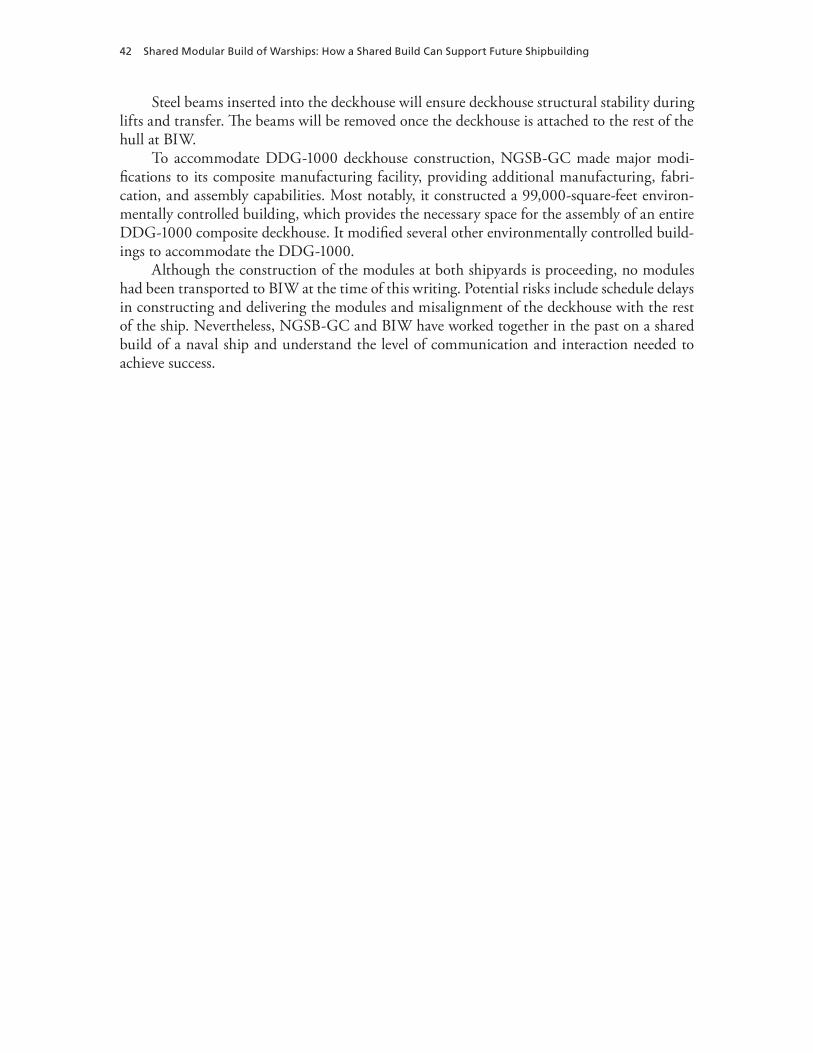
42 Shared Modular Build of Warships: How a Shared Build Can Support Future Shipbuilding
Steel beams inserted into the deckhouse will ensure deckhouse structural stability during lifts and transfer. The beams will be removed once the deckhouse is attached to the rest of the hull at BIW.
To accommodate DDG-1000 deckhouse construction, NGSB-GC made major modi-fications to its composite manufacturing facility, providing additional manufacturing, fabri-cation, and assembly capabilities. Most notably, it constructed a 99,000-square-feet environ-mentally controlled building, which provides the necessary space for the assembly of an entire DDG-1000 composite deckhouse. It modified several other environmentally controlled build-ings to accommodate the DDG-1000.
Although the construction of the modules at both shipyards is proceeding, no modules had been transported to BIW at the time of this writing. Potential risks include schedule delays in constructing and delivering the modules and misalignment of the deckhouse with the rest of the ship. Nevertheless, NGSB-GC and BIW have worked together in the past on a shared build of a naval ship and understand the level of communication and interaction needed to achieve success.

43
APPENDIX C
LPD-17 Case Study
The LPD-17 San Antonio–class amphibious transport ships are designed to carry aircraft, land-ing craft air cushioned, and expeditionary fighting vehicles. Typically, the San Antonio–class vessels are built at the NGSB-GC shipyards. Facing resource limitations, NGSB-GC out-sourced some units to other builders for several hulls (see Table C.1). In this case study, we dis-cuss NGSB-GC interactions with BIW on the build of LPD-24. We then describe interactions within the NGSB shipyards manufacturing the LPD-17 class. Lastly, we discuss the NGSB-GC interactions with other steel fabricators to supply modules for the ships in this class.
NGSB-GC and BIW Interactions on LPD-24
In order to meet shipbuilding scheduling commitments for the LPD-24 USS Arlington, NGSB-GC signed a fixed-price subcontract with BIW to build several LPD-24 units and transport them via barge to the NGSB-GC facility in Pascagoula, Mississippi, for assembly.
Table C.1Shared Build of LPD-17–Class Ships
Shipyard LPD-17 LPD-18 LPD-19 LPD-20 LPD-21 LPD-22 LPD-23 LPD-24 LPD-25
Gulfport x x x x x x x x x
Avondale x x x x x x x x x
Ingalls x x x x x x x x x
Huber x x x x x x x x x
Tallulah x x x x x
Signal x x x x
Newport News x
BIW x
Tecnico x
Atlantic Marine x

44 Shared Modular Build of Warships: How a Shared Build Can Support Future Shipbuilding
Design and Construction Plan
NGSB provided all the drawings and work packages to BIW. Under the subcontract, BIW was responsible for the fabrication, assembly, selected outfitting, primer coat, and barge load out for 13 LPD units. Figure C.1 illustrates some of these.
NGSB-GC’s decision about which units to subcontract to BIW was reported as a “rela-tively complex decision process and considers a lot of things,” including where NGSB-GC was in the build process and what physical resources and worker capacity were available (Fein, 2008). In fact, the yards collaborated to match requirements for types of units with available capacity and manning resources at BIW.
Figures C.2 and C.3 show examples of unit construction.
Figure C.1LPD-24 Inboard Profile: Assembly Units
SOURCE: Bilodeau (2009, slide 3). Used with permission.
RAND TR852-C.1
LPD 24 units build by BIW
Figure C.2Example LPD-24 Unit Being Lifted at Bath Iron Works
SOURCE: Bilodeau (2009, slide 4). Used with permission.RAND TR852-C.2

LPD-17 Case Study 45
Shipyard Collaboration Methods
The design for the units was based on paper drawings. There was extensive liaison between the yards to ensure that the information-transfer process evolved smoothly. In addition to draw-ings, the statement of work for each unit was defined on work-authorization bills for each trade. NGSB-GC also provided numerical control data for fabrication of plates and shapes, which BIW converted to its machine language. These liaisons were often between technical workers, including communication between the yards at the deck-plate supervisor level, and occurred across all different skill sets, including, for example, piping and structure. This cross-yard communication was essential because there were basic differences between the yards in how they constructed the units: Neither yard knew the typical size of metal plates used in the other yard; there were differences in how the yards lift and handle items; BIW preoutfitted units with ventilation, wire-ways, and equipment supplied by NGSB-GC. BIW completed the units at less than the initial cost estimate, a month ahead of schedule, and with no significant surprises in the interface/integration phase. Inspection of units for workmanship and com-pleteness was accomplished by on-site NGSB-GC quality-assurance personnel and by supervi-sors of shipbuilding, conversion, and repair (SUPSHIPs) Bath under memoranda of agreement with SUPSHIP Gulf Coast. Unit-transfer packages were provided by BIW to document the completed statement of work at the work-authorization level.
Transportation Arrangements
The completed units were transported to NGSB-GC’s yard using two barges; the location of the yards is in Figure C.4.
NGSB-GC Interactions with Subsidiary Shipyards on LPD-17–Class Construction
NGSB-GC builds the LPD-17 class, with construction of various units spread across its yards in Gulfport, Avondale, Ingalls, and Tallulah. Each yard has unique capabilities and work prac-
Figure C.3Example LPD-24 Unit Under Construction at Bath Iron Works
SOURCE: Bilodeau (2009, slide 4). Used with permission.RAND TR852-C.3
46 Shared Modular Build of Warships: How a Shared Build Can Support Future Shipbuilding
tices that must be taken into account during manufacturing. As one company, NGSB-GC has a greater ability to manage the four shipyards than is possible in a traditional shared build among different companies. Nonetheless, there are some challenges.
Resource considerations influenced where to build the units. These issues varied consid-erably by hull. LPD-17 began construction in Avondale and finished assembly and testing at Ingalls. LPD-18 was erected in Avondale and assembled with units from Gulfport, Ingalls, and Avondale. LPD-19 was erected at Ingalls, with units from Gulfport, Ingalls, and Avon-dale. LPD-20 was erected at Avondale, with units from Gulfport, Tallulah, Ingalls, and Signal. LPD-21 was also erected at Avondale, with units from Tallulah, Ingalls, and Signal. LPD-22, 23, and 24 followed a similar build process, except with major outsourcing to compensate for resource impacts from Hurricane Katrina.
Differences in equipment and facilities require different manufacturing aids and fabri-cation processes at each facility. Changes in planning also arise from collective-bargaining arrangements that affect how work is assigned to trades. Crane capacity and material-handling equipment drive suboptimization of unit sizes and weights to suit the limiting yard capabilities. The decision to build ships at Avondale allowed NGSB-GC to standardize production pro-cesses based on the capabilities of all the yards. An important role in risk reduction was played by the common quality-assurance systems that were implemented at the various yards via an initiative separate from the LPD program.
By the time LPD-25 was constructed, NGSB-GC had restabilized its resources and cen-tralized more construction. Because all NGSB-GC yards now use the same planning and engi-neering software, units are constructed from the same designs, and accuracy-control personnel conduct alignment checks to ensure proper assembly. Almost all the 210 units for LPD-25 were built in Avondale. Two composite units were made at the specialized Gulfport facility; two
Figure C.4Shipyards Involved in the Construction of LPD-24
RAND TR852-C.4
ME
EB
NGSB-GCPascagoula
NGSB-GCGulfport
NGSB-GCTallulah
SignalInternational
NGSB-GCAvondale
NGSB-GCIngalls
Tecnico
AtlanticMarine
NGSB-NN
BIW

LPD-17 Case Study 47
stern gate units were outsourced to Huber; and six small units were allocated to Tallulah. The primary purpose of consolidating the construction and erection in Avondale was to maximize the learning curve from hull to hull.
The LPD class encountered some planning problems in constructing initial hulls. Each yard possessed unique capabilities that had to be considered. The complexities of the LPD hull required build and test strategies that were very different from previous ones. A revamped build strategy, developed during LPD-22 through LPD-25, sought to address these issues. These problems were not unique to a shared-build strategy but reflected a more-general issue of adapting a build strategy that matches the complexity of the hull. The complexities of the LPD design require build and test strategies very different from those employed on prior builds of amphibious assault ships. Survivability and ship integration features incorporated into the design increase the density of outfitting and installed systems throughout the ship.
One of the key lessons learned in this shared-build strategy is the importance of repeat-ing construction processes to maximize the learning curve within a shipyard. Optimizing the throughput of facilities to advance the learning curve can minimize program risk. Unit assem-bly can be less risky if all builders use the same software, planning processes, and construction processes. Builders should focus attention on the accuracy-control points of the module to ensure smooth integration.
NGSB-GC Outsourcing on LPD-17–Class Construction
Because of resource constraints resulting from Hurricane Katrina, NGSB-GC outsourced manufacture of preoutfitted units for hulls LPD-20 through LPD-24 to various manufactur-ers, such as Signal, Atlantic Marine, and Tecnico. With resources restabilized for LPD-25, NGSB-GC decided to fabricate the units only within its subsidiary shipyards in order to main-tain closer control of unit quality and schedule.
The NGSB-GC Ingalls yard managed these subcontractors. Signal International’s Texas facility had prior experience with steel fabrication, so NGSB-GC asked it to build some steel portions, as well as some outfitting, for LPD-20 through LPD-23. NGSB-GC deployed plan-ning teams to assist Signal. When Hurricane Rita damaged much of Signal’s facilities, the LPD units were brought to NGSB-GC for completion. From the very beginning, Ingalls pro-vided Signal with detailed paper drawings of the steel plates, ventilation, and pipes; a local NGSB-GC team was established to help Signal. As the learning curve improved, Signal was able to manufacture the units independently. These accuracy issues were of the same approxi-mate magnitude as those encountered within NGSB yards and not unique to outsourcing.
NGSB-GC also outsourced units to Tecnico and Atlantic Marine. For each outsourced unit, a statement of work for each builder defined the requirements and configuration. NGSB-GC tracked weekly progress reports and performed inspections to validate the constructed units. Measurements at key points ensured that the units could be integrated with the rest of the ship. Because of the time urgency for LPD-22 and LPD-23, NGSB-GC entered a cost-plus contract with Signal. This was later converted to a fixed-price contract signed with Atlantic Marine and Tecnico, which were more cost-efficient.
In general, NGSB-GC believes that the outsourced units were more costly than they would have been had the units been built at NGSB-GC shipyards. Other drawbacks NGSB-GC identified to outsourcing included skill levels differing by yard that might necessitate a
48 Shared Modular Build of Warships: How a Shared Build Can Support Future Shipbuilding
revised build strategy, increased management and oversight for multiple build sites, and lower-than-expected learning curves. Nevertheless, outsourcing can be valuable for increasing capac-ity and maintaining schedules.
NGSB-GC learned several key lessons from its outsourcing experience:
• Have a defined statement of work. Have an upfront clear definition on who will do what from design development to lofting, high- and detailed-level planning and scheduling, material procurement, project management and reporting, and manufacturing and deliv-ery of identified products.
• Understand manufacturing processes. For the interfaces, all functions need to under-stand the statements of work for all players. For example, if one organization is building a deckhouse for another’s ship and it is expected to be delivered fully outfitted, then the delivering yard needs to know whether main power cables pulled through the deckhouse must be long enough and coiled at delivery so that, when the deckhouse is installed, there is sufficient cable to run from the interface to the source or sink of the power.
• Have accuracy-control measures and quality agreements. There is a need for shared accuracy-control data, especially for interfaces.
• Have a well-designed configuration-management process between all players to track and manage changes in design, plans, and schedules, and have a quick circuit to respond to problems.

49
APPENDIX D
Virginia Case Study
The Virginia-class nuclear-powered attack submarine is a multimission submarine that is replacing the aging Los Angeles–class submarines. Construction of the 30 planned hulls, which began in 1996, is being shared by the EB yard in Groton, Connecticut, and the NGSB yard in Newport News, Virginia. To date, six hulls have been delivered to the Navy. In this appendix, we describe the history of the shared-build effort and the current processes to ensure successful deliveries and reduce cost.
Contracting Plan
The end of the Cold War brought force-structure reductions and spending decreases that made the support of two nuclear-capable submarine shipyards seem untenable. There were insufficient submarines being ordered to sustain the workforce at both yards. The Navy ini-tially planned to relegate submarine construction to EB and retain Newport News Shipbuild-ing (NNS, which was later acquired by Northrop Grumman to become NGSB-NN) as the only aircraft-carrier construction shipyard. Design of the new attack submarine, subsequently renamed the Virginia class,1 would be awarded to EB.
By 1996, the economic climate had changed, and competition was encouraged to reduce cost. Congress was determined to retain NGSB-NN as a submarine shipbuilder and pushed forth a competition plan under the FY 1996 Defense Authorization Act. Under that act, Con-gress sent construction of the first and third ships of the Virginia class to EB and the second and fourth to NNS. Based on this competition, the Navy would select one shipyard to build the remaining hulls. The Navy and the two shipyards, however, were concerned with the affordability of the plan. The Navy also feared possible legal troubles from an unbalanced competition because NGSB-NN did not have the specialized facilities required to build the Virginia class and EB had already begun the design process.
At the same time, an aging SSN fleet,2 along with a costly Seawolf program that was canceled after three hulls, put pressure on the Navy to make the Virginia program both timely and successful. In order to keep the program alive, the shipbuilders agreed to team together on the Virginia class, guaranteeing a split of the design and construction work, rather than under-going a lengthy competition that might jeopardize the entire program. Congress eventually agreed to amend the legislation appropriately.
1 To avoid confusion, we use the Virginia class name throughout this study, regardless of the historically accurate name.2 SSN is an abbreviation representing a nuclear-powered fast-attack submarine.

50 Shared Modular Build of Warships: How a Shared Build Can Support Future Shipbuilding
In February 1997, the teaming effort on the Virginia class was formally announced. EB and NGSB-NN went from being competing archrivals to being teammates on a complex effort. With the pressures on the program, both shipyards quickly began to work together. Management at both companies made teaming an absolute priority—a top-down endorse-ment that contributed to this rapid cultural shift. Teaming was discussed before the formal announcement, helping smooth the transition.
The Virginia-class contract set EB as the prime contractor and NGSB-NN as the key sub-contractor. This placed most of the accountability on one company, a stark contrast with the DDG-1000’s contract with four primes. Although EB was the prime contractor, work-share agreements flowing from the teaming agreement made it and NGSB-NN equal partners in the effort.
Another key component for motivating the teaming arrangement was the Navy’s deci-sion to buy the first four Virginia-class submarines in a block. This provided program stabil-ity, allowed long-term purchases of material, and enabled maintenance of the vendor base. By allowing EB and NGSB-NN to retain 90 percent of any savings below the cost target, the Navy provided incentives for both partners to work together to reduce the total cost on the fixed-price contracts for future hulls.
Design and Construction Plan
The early agreements to split the construction and profits equally played a critical role in set-ting a collaborative tone. The shipbuilders characterized the teaming arrangement as healthy competition, with each yard having a motive to point out flaws and encourage improvements in the other.
Because EB had already begun the design process, it was the primary design agent and shared all the design data with NNS. The construction work-share agreement is illustrated in Figure D.1. Under that agreement, NGSB-NN builds the bow, the stern, the weapon han-dling, the habitability, and the auxiliary machine room (AMR) spaces. EB builds the pressure hull, the CCS, and the engine-room modules. Because the Navy wanted to maintain nuclear submarine capabilities at each shipyard, EB and NGSB-NN alternate construction of the reac-
Figure D.1Work-Share Agreement by Electric Boat and Northrop Grumman Shipbuilding—Newport News for Virginia-Class Submarines
SOURCE: FAS. Used with permission. RAND TR852-D.1
Newport News Shipbuilding
Electric Boat Corporation
Each company will build a reactor plant module
Sail
Stern BowCCS
Weapons
Psgwy Habitability
AMR AMR/Hab

Virginia Case Study 51
tor plant and some AMR/habitability spaces. The final outfitting, testing, and delivery also alternate between the yards by hull.
The work-share agreement was designed to leverage each shipyard’s capabilities. EB had equipment built by Vevey Engineering of Switzerland for manufacturing ring sections (Hileman, 1983) and was therefore better equipped to build the parallel midbody pressure hull units. NGSB-NN excelled at building complex shapes, so it was tasked with building the hemiheads and the main ballast tanks. The CCS module was assigned to EB because the CCS off-hull assembly and test site, a land-based testing platform, was already being built in Groton when the teaming began. The remaining modules were split so as to yield roughly equal total workloads.
Reasons for Shared Build
The shared-build strategy is motivated primarily by the desire to maintain the nuclear subma-rine industrial base at both shipyards. Other potential benefits include protecting submarine construction capabilities from natural disasters or other threats jeopardizing any single yard, broadening the geographic support for the Virginia class, keeping future competition open, and maintaining a higher surge build capacity (O’Rourke, 1997).
Shipyard Collaboration Methods
The complexity of submarine design, and the large number of interfaces between EB and NGSB-NN products, demanded a high level of interaction for success. Many supermodules assembled in NGSB-NN had modules built by EB, which, in turn, had submodules originat-ing at NGSB-NN, which, in turn, had individual components built at EB. A concerted effort from design to construction to assembly is critical for avoiding costly rework and ensuring smooth assembly.
Design
EB completed the baseline design with some input from NNS. As the principal design agent, EB used and developed design tools that provided NNS, the government, and other contrac-tors access to the most-recent design data. When the decision was made to share the build, detailed design was complete for only some of the EB modules. NGSB-NN sent personnel to support EB in completing detailed design for the modules. The designs EB produced used EB terminology, processes, and policies. Therefore, NGSB-NN converted EB design drawings to NGSB-NN terms.
EB and NGSB-NN used the integrated product and process development approach for the Virginia class, making builders an integral part of the design process. This process allowed NGSB-NN to have input into the design. Design build teams from NGSB-NN ensured that the design matched shipyard capabilities and suggested revisions as necessary. Because the two shipyards were digitally connected, design changes from EB immediately reached NNS. At first, these design changes came at such a rapid pace—about 400 weekly—that construction was constantly adapting.

52 Shared Modular Build of Warships: How a Shared Build Can Support Future Shipbuilding
Construction
EB and NGSB-NN collaborated intensely on all phases of the Virginia-class construction effort. During the early phases of the project, NGSB-NN and EB negotiated the details of the work-share agreement at the piece and part levels. These negotiations continue with innova-tions in process.3 The negotiations also had to reconcile the different processes each shipyard employed. Throughout the negotiation process, the emphasis was on making business-case decisions to determine the best course of action. For example, NGSB-NN spent a year con-vincing EB that its method of beveling pipes (a J-bevel) was just as efficient and robust as EB’s method (V-bevel) and did not need to be changed.4 Some business decisions were difficult to make. EB was building the primary shield tank in the final assembly area at Groton when it decided to send the tank to NGSB-NN because it eliminated dual learning curves. This was not a popular decision among the EB shipyard workers. Overall, the workload was split evenly, with negotiations to maximize efficiency.
Fifteen functional-area teams identified the processes and systems required to share build of the Virginia class. These teams included design-data transfer, accuracy and tolerance control, and material procurement. During construction, there was intense interaction among subject-matter experts at both yards to identify critical risk areas for integration and work through the solutions. The interactions were so extensive that EB chartered daily flights between EB and NNS, allowing personnel from each yard to visit the other every day.
Both shipyards interacted to reduce cost and improve process. Over time, the build pro-cess has changed to account for these innovations. Outfitting is increasingly being consoli-dated, and the modules are getting larger. The hull was originally built in ten modules but has been consolidated to four supermodules. Some of these changes were discovered through necessity. When NGSB-NN construction of a module for the first hull was delayed, the yard began doing some of EB’s work on the module in parallel so as to maintain schedule. This was found to be more efficient, and, subsequently, some work shifted to NGSB-NN.
Assembly
Both shipyards had experience with modular construction techniques. Ensuring that the mod-ules fit together during assembly was not unique to a shared-build strategy. Neither shipyard reported significant accuracy-control issues. Modern measurement techniques, coupled with a tight adherence to a common design database, ensured that there were no surprises during assembly.
Critical to success was piloting this entire process by prototyping a part. This prototyp-ing stressed all phases of the build process, from design to planning to construction to quality assurance. Prototyping was put well ahead of the start of construction, allowing subsequent time to make any needed changes to the whole process. For an effort of this complexity, minor issues will doubtless develop as the hulls are being built.
3 The program continues, and many of these processes are still in use.4 NGSB-NN’s workforce uses the J-bevel across all projects, including CVN construction (CVN is an abbreviation repre-senting a nuclear-powered aircraft carrier). Since pipe welders might flow between the CVN and Virginia-class platforms, a uniform process within the yard was critical to minimizing cost on both programs.

Virginia Case Study 53
IT Systems
A key lesson learned during the early phases of the effort was the need to maximize uniformity between team members regarding the systems used, from design to engineering tools to busi-ness processes. This was difficult, as there were nearly four-dozen software systems that dif-fered between the yards. For some critical systems, such as a common construction drawing index, or a common master part-number catalog, uniformity was enforced and a single system used. Nevertheless, IT tools were largely kept different because the IT architecture was so deeply ingrained in the shipyard organization that changing would have been too costly. More than 60 processes and systems were linked or developed to allow the transfer of information between the two shipbuilders, including functional areas, such as welding, quality, and design data. Because the design suites were different, data translators were required for this exchange.
Transportation Arrangements and Facility Constraints
Supermodules of up to 1,450 tons were transported between EB and NGSB-NN on EB’s sea-shuttle barge, as shown in Figure D.2; the locations of the two yards are shown in Figure D.3. Commercial barges and trucking also moved parts, fixtures, and modules between the yards. Nevertheless, transportation was not significantly more difficult than that for single-yard con-struction. For the construction of the Los Angeles class, NGSB-NN had brought by barge large units from other facilities, and EB had to move modules between its Groton and Quonset Point shipyards.
Figure D.2A Supermodule Sits Aboard the Sea Shuttle at Quonset Point
SOURCE: Bodo (2009). Used with permission. RAND TR852-D.2

54 Shared Modular Build of Warships: How a Shared Build Can Support Future Shipbuilding
There was minimal facility cost incurred specifically to accommodate the teaming arrangement. NGSB-NN had to install a landing (concrete piers) to accommodate the sea shuttle. The main driver for facility construction is the pending increase in throughput from one Virginia hull per year to two. To accommodate this, NGSB-NN is enlarging some facili-ties, such as the module assembly facility.
Figure D.3Shipyards Involved in the Construction of the Virginia Class
RAND TR852-D.3
ME
NGSB-NN
EB

55
APPENDIX E
UK Type 45 Destroyer Case Study
The Type 45 class is the latest UK anti–air warfare destroyer (Figure E.1). It replaces the Type 42 class, a design that is almost 40 years old. Originally, MOD planned to acquire 12 of these ships, but budget constraints have led this number to be reduced to six (Table E.1). BAE Systems Surface Ships is using two yards, Portsmouth and Glasgow, to deliver the ships.1 The supplying yards were separately owned by VT Group (Portsmouth) and BAE Systems Surface Solutions2 (Glasgow) but later became a joint venture with the two companies forming BVT Surface Fleet (BVT) and, after BAE bought out the VT Group interest, BAE Systems Surface Ships. As of this writing, the lead and second ships, HMS Daring and HMS Dauntless, have been delivered to the Royal Navy. Three more are on trials or fitting out, and the sixth is in the latter stages of construction. In this appendix, we discuss the evolution of the program and highlight key aspects of the shared-build process.
1 The Glasgow site comprises two originally distinct yards: Govan on the south side of the River Clyde and Scotstoun on the north.2 BAE Systems Marine was another name for BAE Systems’ shipbuilding business during this period.
Figure E.1The Type 45 Destroyer
SOURCE: NAO (2009). Used with permission.RAND TR852-E.1
Helicoper landing deck—for Merlin, Lynx,or Chinook
Long-range radar
Communications mast
SAMPSON radar—unique to the Type 45.Multifunction radar for anti-air missile system.
Sylver launchers forPAAMS—hold theAster missiles
4.5 inch Mark 8 gun
WR21 gas engines

56 Shared Modular Build of Warships: How a Shared Build Can Support Future Shipbuilding
Project Background
MOD began considering the replacement program for the Type 42 destroyers in the 1980s when it became apparent, following the Falklands War, that the current ships and their air defense systems were becoming obsolete. To replace the Type 42, the UK initially joined the North Atlantic Treaty Organization (NATO) frigate replacement for the 1990s (NFR-90) project and later the Horizon common new-generation frigate (CNGF) program with France and Italy. When the UK was unable to agree with France on prime-contractor assignments for the CNGF, it left the project and immediately commenced the Type 45 program, using some of the CNGF and NFR-90 work as a basis.
MOD was undergoing change as it sought to reduce its own project-management costs and implement a new procurement process that attempted to place risk with contractors. The cost-reduction process led to smaller project and support teams with fewer highly skilled spe-cialists; those skills needed were to be supplied by industry. For example, MOD sought to use industry as the design authority for its new shipbuilding programs. Fixed-price contracts, from a clear description of requirement, were seen as a major step to reducing risk to the department.
The British shipbuilding industry was consolidating during this period. Yards, such as Harland and Wolff in Northern Ireland, and Swan Hunter in the northeast of England, were moving away from shipbuilding and into ship repair. The ownership of still other yards was changing with, for example, Marconi Naval Systems becoming part of BAE Systems as part of General Electric Corporation’s (GEC’s) sale of Marconi Electrical Systems to British Aerospace (BAe). In this fluid commercial environment, MOD placed an order in 1999 with Marconi Electronic Systems, with BAe assistance, to study options for the Type 45 destroyer. Subse-quently, MOD made BAE Systems (formed from Marconi Naval Systems and BAe’s Defence Systems) the PCO with overall design and manufacture responsibility for the Type 45 program.
At this stage, MOD asked RAND to help it understand the options available for execut-ing the program. That work (Birkler et al., 2002) influenced the decision to follow a shared-build strategy involving the then Vosper Thorneycroft (which would move to Portsmouth as
Table E.1Ships of the Type 45 Class and Launch Dates
Ship Launch Date
HMS Daring January 2006
HMS Dauntless January 2007
HMS Diamond November 2007
HMS Dragon November 2008
HMS Defender October 2009
HMS Duncan October 2010
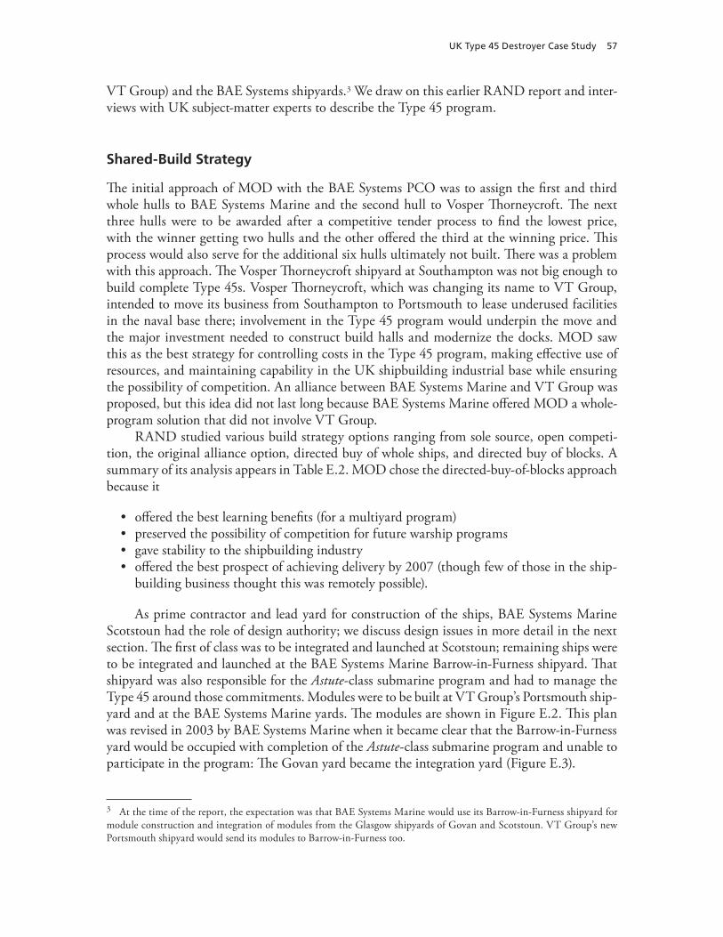
UK Type 45 Destroyer Case Study 57
VT Group) and the BAE Systems shipyards.3 We draw on this earlier RAND report and inter-views with UK subject-matter experts to describe the Type 45 program.
Shared-Build Strategy
The initial approach of MOD with the BAE Systems PCO was to assign the first and third whole hulls to BAE Systems Marine and the second hull to Vosper Thorneycroft. The next three hulls were to be awarded after a competitive tender process to find the lowest price, with the winner getting two hulls and the other offered the third at the winning price. This process would also serve for the additional six hulls ultimately not built. There was a problem with this approach. The Vosper Thorneycroft shipyard at Southampton was not big enough to build complete Type 45s. Vosper Thorneycroft, which was changing its name to VT Group, intended to move its business from Southampton to Portsmouth to lease underused facilities in the naval base there; involvement in the Type 45 program would underpin the move and the major investment needed to construct build halls and modernize the docks. MOD saw this as the best strategy for controlling costs in the Type 45 program, making effective use of resources, and maintaining capability in the UK shipbuilding industrial base while ensuring the possibility of competition. An alliance between BAE Systems Marine and VT Group was proposed, but this idea did not last long because BAE Systems Marine offered MOD a whole-program solution that did not involve VT Group.
RAND studied various build strategy options ranging from sole source, open competi-tion, the original alliance option, directed buy of whole ships, and directed buy of blocks. A summary of its analysis appears in Table E.2. MOD chose the directed-buy-of-blocks approach because it
• offered the best learning benefits (for a multiyard program)• preserved the possibility of competition for future warship programs• gave stability to the shipbuilding industry• offered the best prospect of achieving delivery by 2007 (though few of those in the ship-
building business thought this was remotely possible).
As prime contractor and lead yard for construction of the ships, BAE Systems Marine Scotstoun had the role of design authority; we discuss design issues in more detail in the next section. The first of class was to be integrated and launched at Scotstoun; remaining ships were to be integrated and launched at the BAE Systems Marine Barrow-in-Furness shipyard. That shipyard was also responsible for the Astute-class submarine program and had to manage the Type 45 around those commitments. Modules were to be built at VT Group’s Portsmouth ship-yard and at the BAE Systems Marine yards. The modules are shown in Figure E.2. This plan was revised in 2003 by BAE Systems Marine when it became clear that the Barrow-in-Furness yard would be occupied with completion of the Astute-class submarine program and unable to participate in the program: The Govan yard became the integration yard (Figure E.3).
3 At the time of the report, the expectation was that BAE Systems Marine would use its Barrow-in-Furness shipyard for module construction and integration of modules from the Glasgow shipyards of Govan and Scotstoun. VT Group’s new Portsmouth shipyard would send its modules to Barrow-in-Furness too.
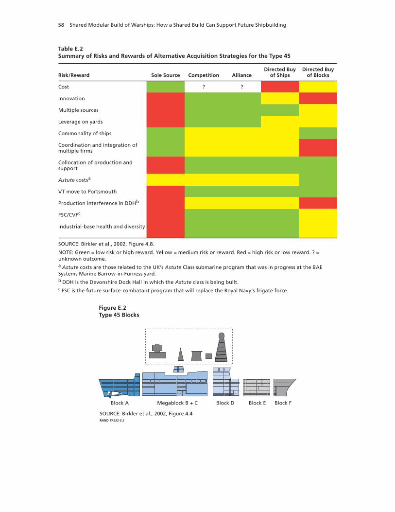
58 Shared Modular Build of Warships: How a Shared Build Can Support Future Shipbuilding
Table E.2Summary of Risks and Rewards of Alternative Acquisition Strategies for the Type 45
Risk/Reward Sole Source Competition AllianceDirected Buy
of ShipsDirected Buy
of Blocks
Cost ? ?
Innovation
Multiple sources
Leverage on yards
Commonality of ships
Coordination and integration of multiple firms
Collocation of production and support
Astute costsa
VT move to Portsmouth
Production interference in DDHb
FSC/CVFc
Industrial-base health and diversity
SOURCE: Birkler et al., 2002, Figure 4.8.
NOTE: Green = low risk or high reward. Yellow = medium risk or reward. Red = high risk or low reward. ? = unknown outcome.a Astute costs are those related to the UK’s Astute Class submarine program that was in progress at the BAE Systems Marine Barrow-in-Furness yard. b DDH is the Devonshire Dock Hall in which the Astute class is being built. c FSC is the future surface-combatant program that will replace the Royal Navy’s frigate force.
Figure E.2Type 45 Blocks
SOURCE: Birkler et al., 2002, Figure 4.4 RAND TR852-E.2
Block A Megablock B + C Block D Block E Block F

UK Type 45 Destroyer Case Study 59
Contract
MOD placed the initial preparation for demonstration (PFD) contract for the Type 45s with Marconi Electronic Systems in November 1999, a few days before Marconi Electronic sepa-rated from GEC and was bought by BAe to form BAE Systems. A second PFD contract with BAE Systems followed and established BAE Systems Bristol as the PCO.4 There followed a much-larger fixed-price contract of $1.8 billion5 for the demonstration and first-of-class manu-facture (DFM) for the first batch of three ships. BAE Systems Marine and Vosper Thorneycroft were both involved in the design of the ship and had expectations of sharing build. MOD hoped that there would then be competition for the next and subsequent batches of the class. Vosper Thorneycroft needed agreement for more ships, however, to make its move to Ports-mouth. The DFM was extended in 2002 to become a fixed-price contract for the shipbuilding work for six ships, including integration of the air defense system. At this point, though, BAE Systems Marine offered a whole-program proposal, and, following work by RAND described in the previous section, MOD adopted the shared-build strategy.
MOD reviewed the program in 2006 and concluded that key aspects of the project were failing. For example, there was misalignment in the contracts, with the prime under contract for three hulls but the strategic partners responsible for delivering six hulls, which had been
4 A fuller description of the contract history can be found at the Navy Matters website (Beedall, undated).5 GBP1.2 billion at GBP1:$1.5. We use this approximate exchange rate for other conversions in this report.
Figure E.3Shipyards Involved in Construction of the Type 45 Class in 2006
NOTE: The yards came together under one company, BVT Surface Fleet Ltd., as a jointventure in 2008. VT Group sold its shipyard interests to BAE in 2009, and the yards formed BAE Systems Surface Ships.RAND TR852-E.3
VT GroupPortsmouth
BAE ScotstounBAE Govan

60 Shared Modular Build of Warships: How a Shared Build Can Support Future Shipbuilding
the minimum needed to allow VT Group to form the new yard at Portsmouth. Shipbuilding performance was not criticized. The review led to a renegotiated six-ship contract with changed project responsibilities and a variable pricing mechanism with incentives for the shipbuilders. In 2008, BAE Systems Marine and VT Group formed a joint venture, BVT, which became solely responsible to MOD for delivery of the ships. BAE Systems bought out VT Group inter-est in 2009. The shared-build strategy did not change with any of these alterations. The final cost of the Type 45 program is expected to be $9.7 billion.6
Design
The design of the Type 45 was based on that of the CNGF. MOD had little opportunity to modify the design if it were to achieve the required in-service date for the Type 45; however, it had identified what it wanted to change.7 The short, eight-month period from MOD with-drawal from CNGF to the award of the full-scale engineering development and initial produc-tion contract for Type 45 highlights the pressure under which the decisions were being made. MOD placed significant design responsibility on the PCO and, in turn, the shipyards, remov-ing much of its own skilled workforce from either the design or project-management processes. MOD relied on suppliers, principally the PCO, to assist in the management of design changes. Cost constraints in MOD led to a number of revisions of the original design, as well as the gradual reduction in the number of ships in the program. The PCO incurred costs, too, as it had accepted the design and had undertaken to supply the necessary information to the ship-yards so that they could build the modules. The immature design and lack of detailed design information, which are usually considered the features of first-of-class designs, coupled with a rigid contract, allowed, for example, VT Group to claim compensation from BAE Systems. A review of the program led to the six-ship contract, after which MOD and the contractors (BAE Systems, BAE Systems Marine and VT Group, and then BVT) began to work more closely together with collocated personnel and more-open access to data and information.
The CNGF was not designed for multiple-shipyard, modular build. As a result, the Type 45 inherited some design challenges that fed into design for production for shared build. For example, the operations room (combat information center) crosses blocks C and D. This and similar problems would not have been part of a deliberate modular or shared-build design. Neither was CNGF a mature design that represented MOD’s requirements. Design changes ordered by MOD before the six-ship contract introduced further costs and delays to the program.
6 Cost figures are taken from the National Audit Office’s 2009 report. This figure includes all costs associated with the program, in addition to those for shipbuilding. The actual cost per ship was assessed at $974 million. The National Audit Office is comparable to GAO in the United States.7 In addition to the work-share disagreements, MOD had wanted to change the CNGF design more to meet its own requirements, and this would have needed the partners to compromise further on their needs.

UK Type 45 Destroyer Case Study 61
Construction
There were few problems encountered with the shared build of the Type 45s. VT Group moved its operations from nearby Southampton to its new facilities within the Portsmouth Naval Base. The investment included modern automated steel-cutting machinery, new build halls over existing docks, and a load-out quay for handling module transfers to a barge. VT Group did not intend to compete to build future large warships because its strength was the smaller vessels that were attractive in the export market. The new facilities were tailored for this smaller size of vessel, but with the capability to produce modules for integration elsewhere to produce larger vessels. The facility was ready for use in early 2003, and the first steel was cut there for the bow blocks of the first-of-class HMS Daring (modules E and F) in March 2003. These two modules were connected in Portsmouth before being shipped by barge to the Scotstoun yard on the Clyde. The work on these modules was not complete, however, and VT Group workers traveled to Scotstoun to meet the contractual completion requirements. BAE Systems Surface Ships placed a team of eight quality-assurance personnel at the VT Group yard to ensure that there was a common understanding of the state of the modules that were being built there. A two-inch “green” or “stock” margin was allowed on the modules from Portsmouth, and three point measurements were taken to validate precision of fit. Transportation of the blocks from Portsmouth to Glasgow was by barge (Figure E.4). This cost a single, non recurring $900,000 in engineering costs plus a further $900,000 for each block moved (at 2000 prices).
BAE Systems Marine constructed block A at its Govan yard and transferred this across the river to the Scotstoun yard. Blocks B/C, as a megablock that contained the main machin-ery spaces, and block D were built at the Scotstoun yard and joined to block A. The bow section from Portsmouth was added and the whole ship launched in February 2006. The mast sections, built in Portsmouth, were added to the ship in dry dock. BAE Systems Marine
Figure E.4Type 45 Bow Section on Barge Moving from Portsmouth to Glasgow
SOURCE: Moriarty (2010a). Used with permission.RAND TR852-E.4

62 Shared Modular Build of Warships: How a Shared Build Can Support Future Shipbuilding
was able to use the Govan yard and its slipway for completion of the remaining hulls; all the blocks (A–D) are constructed in the ship block and outfit hall before being moved to the slip-way. The bow sections and superstructures from Portsmouth are then added before the ship is launched. Final outfitting occurs with the vessel alongside. Only the Glasgow yards under-take any of the final test and commissioning work, and these skills have not been exercised at the Portsmouth yard.
The learning curve for Type 45 is shown in Figure E.5. It compares favorably with the theoretical curves of our discussion in Chapter Six, though it would appear that there was more-significant learning from hull 1 to hull 2 than we predicted in our simple model. This is likely due to inefficiency from immature design information and the late ordering of lead items for construction. Further, BAE Systems Surface Ships has achieved better core produc-tivity, so enhancing the effect of first-of-class inefficiency. The figure shows the actual hours for hull 1 and the forecast hours for the remaining ships (as they have yet to be completed). The 120-percent point on the man-hour scale highlights the contingency in the six-ship contract for the first hull to exceed the budgeted build hours; in fact, it met the forecast. The number of man-hours decreased from hull to hull as the construction teams became more familiar with the design and the design itself was completed. The split between construction on land (i.e., on the modules) and afloat (i.e., once the hull is launched) was not constant, with hours on land increasing from hull to hull. During our subject-matter expert interviews for this case study, we were told that, for the previous class of ship built in the UK, the Type 23 frigate, about 33 per-cent of all build man-hours were expended on shore, with the remainder afloat. For Type 45 hull 1, it was about 50 percent; hull 2 was 55 percent; and, for hull 4 (the most-recent figures available), it was 65 percent. Construction ashore, of the modules or inside them, is easier and cheaper than doing the same work afloat. Tools are more-easily available, there is less traveling
Figure E.5Type 45 Forecast Learning Curve
SOURCE: Adapted from House of Commons Public Accounts Committee (2009).RAND TR852-E.5
Perc
enta
ge
of
man
-ho
urs
wh
en c
om
par
ed
wit
h T
ype
45 h
ull
1
100
80
60
40
20
120
20Hull 5Hull 4Hull 3
Type 45 ship
Hull 2Hull 1 Hull 6

UK Type 45 Destroyer Case Study 63
to and from the workplace, there are fewer restrictions on land, and the working conditions are simpler.
Conclusion
The major problems of the Type 45 program were not those of shared build. Despite all the oversight, schedule, and management changes in MOD and the companies involved in deliv-ering the ships, the shipyards have faced and overcome similar problems to those experienced at other yards. Importantly, the shared-build strategy did deliver the stability needed for the businesses to invest in people and facilities. It was also successful in delivering continuous improvement. Government policy toward competition changed in 2005 with the publication of the Defence Industrial Strategy (MOD, 2005). This called for the yards to consolidate so the competition between the Portsmouth and Glasgow yards that the Type 45 build strategy was intended to protect was no longer required.


65
APPENDIX F
UK Future Carrier Case Study
The QEC will replace the existing, smaller aircraft carriers of the Royal Navy. The two new vessels, HMS Queen Elizabeth and HMS Prince of Wales, will be the largest warships ever built in the UK and will become the second-largest aircraft carriers in the world after the U.S. Navy’s nuclear-powered aircraft carriers. The carriers are designed to carry up to 36 of the joint strike fighter aircraft. They will be 64,000 long tons and 865 feet long and 128 feet wide at the waterline. These ships are being built to a mixture of commercial and military standards and will meet a new ship classification, the Lloyds’ Naval Ship Rules. This approach is considered the most affordable, and the program, as one of the largest for MOD, has faced and continues to face considerable financial pressure to control costs.
The UK’s intention to proceed with large carriers was announced at the same time as con-firmation of the Type 45 requirement in the Strategic Defence Review in 1998 (MOD, 1998). Management of the QEC project has been markedly different from the latter program. Even so, political and budgetary considerations have led to delays to the planned in-service dates of the new carriers. Consolidation of the UK shipbuilding industrial base has continued, too, in part as a requirement of the UK MOD in the execution of the QEC program. The project is now in the early stages of construction, with parts of the initial superblocks (each in excess of several thousand tons) being formed at shipyards around the UK. Facility improvements for the construction and support of the new ships are nearing completion in some cases or are about to start in others.
For this case study, we relied on openly available information from websites, such as those of the UK MOD (MOD, undated), BAE Systems (undated), and specialist commentators, such as the Navy Matters website (Beedall, undated). We drew on previous RAND work for the UK MOD, some limited subject-matter expert interviews, and published speeches and reports, mostly from UK media. We first discuss MOD’s changing industrial-base policy before con-sidering the contracting structure used for this program. We then briefly consider available information about the construction process, transportation plans, and facility improvements.
Evolving UK Shipbuilding Industrial Strategy
The UK published its Defence Industrial Strategy in 2005. This contained the maritime indus-trial strategy and identified the requirement for closer MOD management of the shipbuilding industrial base. The review was written cognizant of the problems with the Type 45 program discussed in part in Appendix E, the progress of the QEC project, and realization that com-petition among yards and the owning businesses was no longer effective in the UK defense
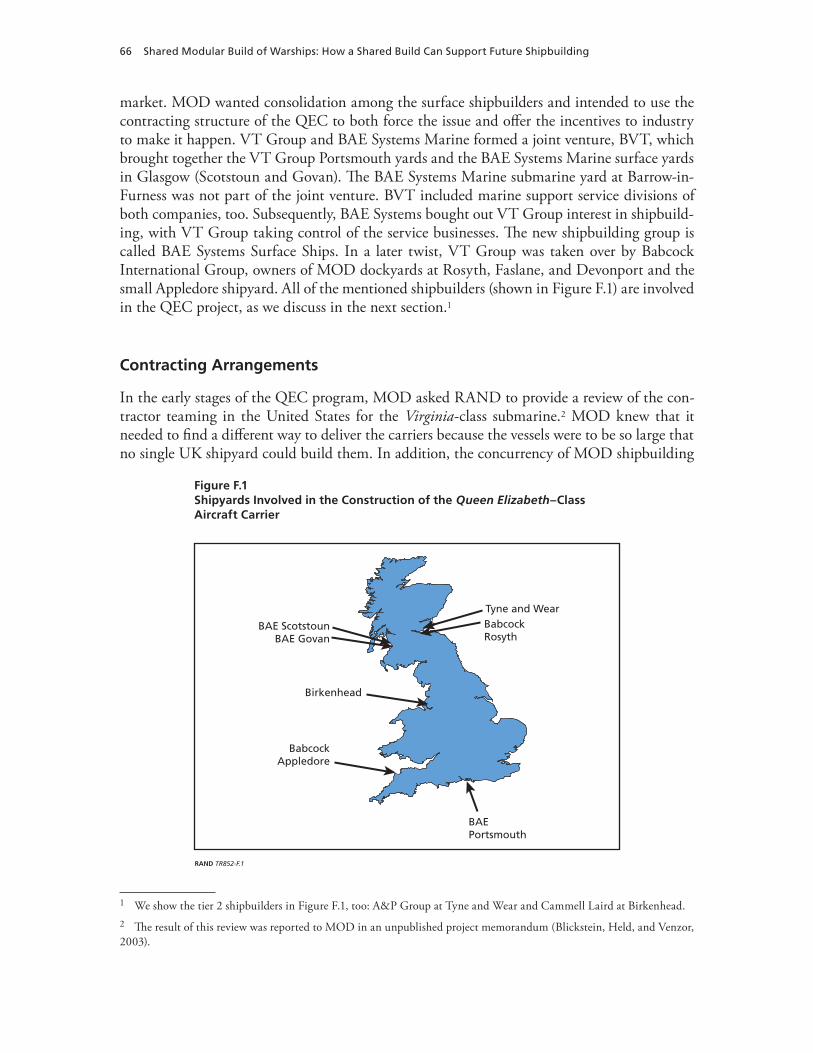
66 Shared Modular Build of Warships: How a Shared Build Can Support Future Shipbuilding
market. MOD wanted consolidation among the surface shipbuilders and intended to use the contracting structure of the QEC to both force the issue and offer the incentives to industry to make it happen. VT Group and BAE Systems Marine formed a joint venture, BVT, which brought together the VT Group Portsmouth yards and the BAE Systems Marine surface yards in Glasgow (Scotstoun and Govan). The BAE Systems Marine submarine yard at Barrow-in-Furness was not part of the joint venture. BVT included marine support service divisions of both companies, too. Subsequently, BAE Systems bought out VT Group interest in shipbuild-ing, with VT Group taking control of the service businesses. The new shipbuilding group is called BAE Systems Surface Ships. In a later twist, VT Group was taken over by Babcock International Group, owners of MOD dockyards at Rosyth, Faslane, and Devonport and the small Appledore shipyard. All of the mentioned shipbuilders (shown in Figure F.1) are involved in the QEC project, as we discuss in the next section.1
Contracting Arrangements
In the early stages of the QEC program, MOD asked RAND to provide a review of the con-tractor teaming in the United States for the Virginia-class submarine.2 MOD knew that it needed to find a different way to deliver the carriers because the vessels were to be so large that no single UK shipyard could build them. In addition, the concurrency of MOD shipbuilding
1 We show the tier 2 shipbuilders in Figure F.1, too: A&P Group at Tyne and Wear and Cammell Laird at Birkenhead.2 The result of this review was reported to MOD in an unpublished project memorandum (Blickstein, Held, and Venzor, 2003).
Figure F.1Shipyards Involved in the Construction of the Queen Elizabeth–Class Aircraft Carrier
RAND TR852-F.1
BAEPortsmouth
BAE ScotstounBAE Govan
BabcockAppledore
Birkenhead
BabcockRosyth
Tyne and Wear

UK Future Carrier Case Study 67
programs was expected to exceed UK capacity (Arena et al., 2005). MOD wanted to find an efficient and effective contracting structure with sufficient incentive for participants to deliver at the best possible price. It chose to adapt an alliance structure that had been used in com-mercial industry—most commonly, the offshore energy industry—in which the shipbuilders share with the ship owners in the profits generated by the ship. Since the carriers would not earn an income, MOD entered the alliance with the ability to cap financial risk in the event of cost escalation and share any savings with all those involved.
In 2005, MOD formed the ACA and continued negotiating with the involved compa-nies to formalize the alliance agreement (in legally binding terms) and the work contracts that would underpin delivery of the ships. Although membership of the ACA fluctuated, its first formal structure comprised the following:
• BAE Systems: design, shipbuilder (BAE Systems Marine), ship systems (BAE Systems Insyte), and support
• Babcock International Group: design, shipbuilder, integrator, and support• Thales Naval: design and ship systems• VT Group: shipbuilding and support• Kellogg Brown and Root (KBR): project-management services• MOD: customer.
In 2007, KBR left the alliance, having completed its function. The consolidation in the maritime industry described in the previous section means that the ACA now involves BAE Systems, Babcock, Thales, and MOD.
The features of the ACA, underpinned by the alliance agreement, are described as follows:3
• single integrated high-performance team• uncompromising commitment to trust, collaboration, innovation, and mutual support• collective ownership of risks and reward• incentive to achieve outstanding performance in prealigned project objectives• full open-book accounting• decisions made on best-for-project basis • culture of no fault, no blame, and no dispute.
MOD had wanted to contract directly with each alliance member in a series of work con-tracts that individually would have described each company’s role and collectively would have delivered the ships. It transpired that, under UK tax law, the delivery of blocks would attract a sales tax of 17.5 percent that was not assessed on whole ships. The ACA agreed to a more-traditional contracting structure to sidestep this tax: BAE Systems is the prime contractor to MOD, with the other ACA members under subcontract. This has not affected the ACA agree-ment and management arrangements for, for example, profit share.
The ACA has established a central office to manage the program. This provides guidance on program governance and enforces the requirements for common processes and languages
3 There is limited literature available to describe alliance contracting, the terms used, and how such arrangements fare in courts. The QEC ACA has not published the contractual details of the prime contracts, subcontracts, and ACA memoranda that underpin the alliance.

68 Shared Modular Build of Warships: How a Shared Build Can Support Future Shipbuilding
across, for example, the different construction yards. The office undertakes project planning and review for the ACA using earned-value techniques.
Design
MOD undertook a competitive design phase in the early stages of the project that was, at the time, expected to lead directly to contract award and construction.4 The chosen design incor-porates elements of each of the submitted designs and has been further refined as the project has evolved. This early work formed the starting point for the next stages of the design process: functional design, spatial design, and production outputs. Multidisciplinary teams undertook the design work, mostly in stages 2 and 3, at different locations across the UK. Three steps were taken to overcome the problems associated with this dispersed network and the different sys-tems in use. A web-based shared data environment tool was developed that allowed designers in different locations and using different systems to manage design activities. Secondly, a data warehouse was established as a live repository of the information data. Finally, object manage-ment was used to build and track elements or components of the ship.
Construction
The ACA decided how to assign the blocks for construction using the principles of the alli-ance agreement. Capacity and capability constraints limited the scope for extensive competi-tion, and the alliance members were chosen in part for the major roles they were to play in construction. The lower hull is being constructed in three large blocks and two “end” units (see Figure F.2): Babcock’s integration yard at Rosyth will build the bow unit, BAE Systems Surface Ships’ yard in Portsmouth is building block 2 and the stern unit, and its Glasgow yards are building blocks 3 and 4 (see Figure F.3). The smaller upper blocks, superstructure blocks, and sponsons were competitively tendered; some of these are to be built at the ACA member yards, while others are to be built elsewhere in the UK, as Figure F.1 shows.
The lower blocks will be taken to Rosyth by barge and floated into the build dry dock with the stern sections first and the bow last. These blocks will be huge: For example, block 3 will be 8,850 long tons, and block 4 will be 10,820 long tons. The center, upper, and sponson blocks, which will be no more than 840 long tons, will be taken to Rosyth and craned into position on the lower blocks. The first steel was cut for lower block 3 in July 2009, and other blocks have since started production in the other shipyards. The first sections of the HMS Queen Elizabeth have begun to arrive from the Appledore shipyard at Rosyth. A single trans-portation contract has been let by the ACA to Henry Abrams, a specialist marine transporta-tion company. The award was for $130 million and makes the one company responsible for all moves of the blocks across the UK. The construction of the two ships is expected to be com-pleted in 2015 and 2018.
4 Information from this section comes from a speech by Alan Johnston (2010).

UK Future Carrier Case Study 69
Figure F.2Block Assignment for HMS Queen Elizabeth, First of Class of the QEC
SOURCE: Moriarty (2010a). Used with permission.NOTE: LB = lower block. CB = center block. UB = upper block. SP = sponson.RAND TR852-F.2
BAE Systems Surface Ships (north)BAE Systems Surface Ships (south)
BabcockA&P Tyne
Cammell Laird
CB04d CB04c CB04b CB04a
CB06
CB06 CB05
SP12
SP11
SP04 SP02
Ramp
Ramp
SP10 SP08 SP06
CB
03d
CB
03c
CB
03b
CB
03a
CB
02e
CB
02d
CB
02c
CB
02b
CB
02a
SP09 SP07 SP05 SP03 SP01
LB01
LB01
LB04 (Excl T & U) LB03 LB02
UB07UB14
LB05
CB05a
CB05b
CB04 CB03CB02
Figure F.3Early Stages of Construction of HMS Queen Elizabeth Lower Block 3 at BAE Systems Surface Ships Govan Shipyard
SOURCE: Moriarty (2010a). Used with permission.RAND TR852-F.3

70 Shared Modular Build of Warships: How a Shared Build Can Support Future Shipbuilding
Facilities
There is little requirement for major modifications to any of the shipyards that are constructing the blocks for the QEC. BAE Systems Surface Ships is building the largest of the keel blocks at its modern facilities in Portsmouth and Glasgow—these yards have completed (or are about to complete) construction of the last Type 45—and only minor investment in new cranes or other facilities is needed. Modular build is new to some of the yards, such as Appledore in the south-west and Babcock at Rosyth; in the case of the former, its early modules, such as the bulbous bows, are being sent to Rosyth for inclusion into larger blocks that will be constructed there. The Rosyth dockyard has specialized in maintenance of ships for the Royal Navy rather than construction; the bow block and integration of the other blocks that will form HMS Queen Elizabeth will be the first construction undertaken at the yard. The construction facilities are undergoing extensive improvement to accommodate the size of the new carriers, to provide the facilities to integrate the blocks and then launch the built ships, and to allow for testing and commissioning of the ships in a nontidal basin. In particular, for integration of the center and upper blocks and sponsons, a large goliath crane, capable of lifting about 1,000 long tons, is to be erected over the build dock.
The Rosyth yard was chosen because it had the best existing facilities capable of accom-modating and building ships of the intended size of the QEC. Dock 1 was originally built in 1916 and sits within the largest nontidal basin in the UK. Even though its existing length was sufficient, its entrance was too narrow, and the dock had a v-shaped profile that was unsuitable for the very wide, square-shaped hull of the carriers (see Figure F.4). The entrance has been widened by 30 feet, to 130 feet overall, and the dock walls opened to fit the carrier blocks. In addition, a second gate is being added to the dock so that new blocks can be floated in while the other sections remain dry. The dock floor is being fitted with a combined lifting and skid-
Figure F.4Widening Work on Rosyth Dock 1
SOURCE: Moriarty (2010a). Used with permission.RAND TR852-F.4

UK Future Carrier Case Study 71
ding arrangement to allow for the blocks to be handled once the dock is dry. The conversion work of dock 1 is to cost $52 million.


73
APPENDIX G
LHD Mistral and Tonnerre
The Mistral is an amphibious assault ship (LHD), known in French as a BPC. The first French military surface ship entirely propelled with electricity, it is larger than its predecessors, the polyvalent intervention ships of the Foudre and the Ouragan classes.
The first two BPC, the Mistral and the Tonnerre, were built almost simultaneously, with the construction of the Mistral starting in July 2002 and that of the Tonnerre in December 2002. The cost of the overall project was €530 million, with the ships placed in service three to four years after construction began (DCN, 2002).
Design and Construction Phase
The DGA (Direction générale pour l’armement)’s Naval Program Services in the French defense ministry contracted DCN—which, at the time, was a government-owned shipyard—to build the first two BPCs. DCN, in turn, subcontracted Chantiers1 in Saint-Nazaire (France) and the Stocznia Remontowa yards in Gdansk (Poland) to build several sections of the ship’s hull. The locations of these shipyards are shown in Figure G.1.
Design
Starting in 1998, using a general design of DCN, DCN and Alstom-CA jointly completed the detailed design of the class under the overall management of DCN. One department at DCN, Etablissement Ingénierie Constructions Neuves, designed the rear of the ship, as well as the island superstructure. Alstom-CA designed the front of the ship. Another department at DCN, Etablissement Systèmes de Combat et Equipements in Toulon, designed the combat system. Thales designed the communication system (DCN, 2002). As prime integrator, DCN set the norms for the signal network and the electrical grid.
There was no digital modeling for the BPC because it was not widely available when design started. Everything was done by traditional methods, with some use of CAD but with an ultimate reliance on paper plans rather than a digital model. As a result, software incompat-ibility between construction sites was never an issue.
1 In 2008, Chantiers de l’Atlantique changed its name to STX France. The name Chantiers de l’Atlantique is used in this case study for the construction of the Mistral and Tonnerre (2002–2007), but its subsequent name, STX France, is used when the construction of the Dixmude (2009–2012) is mentioned.

74 Shared Modular Build of Warships: How a Shared Build Can Support Future Shipbuilding
Construction
Chantiers was in charge of the front sections of the Mistral and the Tonnerre. This area has the living quarters for the crew and troops, as well as the hospital and command post. There was an attempt to apply, as much as possible, civilian methods of shipbuilding. The BPC can accommodate 400 troops, 200 staff members, and 160 crew members (Government of France, undated [a]). Cabins were built individually on land with all equipment (including beds, lava-tories, and connections for water conducts and ventilation systems). The 150 workstations of the embarked command post were also modular and could be arranged in a flexible way (Annati, 2007).
DCN in Brest was in charge of the rear section, where the defense systems are located, as well as the well deck, the ammunition stores, and helicopter hangars (Figure G.2). DCN was also in charge of the signal network and radars. It also integrated the combat system for the assembled hull.
DCN subcontracted two-thirds of the hull of the rear section to the Polish yard Stocznia Remontowa in Gdansk. Stocznia Remontowa was tasked with building the lower section of the hull, while DCN remained in charge of the upper levels of the hull (including the hangars for helicopters).
Trials of the different sections were conducted at each construction site before assembly in Brest. DCN supervised the final trial of the assembled ship in Brest (DCN, 2002).
Figure G.1Shipyards Involved in the Construction of the Mistral Class
RAND TR852-G.1
Stocznia RemontowaGdansk, Poland
ChantiersSaint-Nazaire
DCNBrest

LHD Mistral and Tonnerre 75
Reasons for Shared Build
There were two main reasons to build these ships at three different yards:
1. Ensure faster construction. Splitting the construction among three yards was expected to speed the construction process. In addition, the French yards had, at the time, a space issue. Chantiers was already very busy with the building of the Queen Mary 2. DCN was finishing the Charles de Gaulle aircraft carrier. Sharing the building of the Mis-tral and Tonnerre between Brest, Saint-Nazaire, and Gdansk made it possible to start construction in spite of existing commitments. The French government wanted the BPCs relatively quickly, because the ships they were to replace were becoming very old. Indeed, the Mistral was sent on its first mission (Operation Baliste) to Lebanon in July 2006, shortly after it was brought into service.
2. Benefit from each yard’s niche specialization. Chantiers usually builds cruise ships, while DCN specializes in military equipment and ships and the Polish yard specialized in hulls. Each yard was given to do what it does best. This specialization helped reduce costs.
Figure G.2Building of the Rear Section of the Mistral by Direction des Constructions Navales in Brest, September 2003
SOURCE: Roche (undated). Used with permission.RAND TR852-G.2

76 Shared Modular Build of Warships: How a Shared Build Can Support Future Shipbuilding
Shipyard Collaboration Methods
Chantiers and DCN had worked together on the construction of an oil-drilling platform shortly before construction began on the Mistral and the Tonnerre. Chantiers had been in charge of building the living quarters on the platforms. The last of three platforms was finished by 2001, shortly before DCN and Chantiers again worked together on the Mistral class. The teams who worked on both projects were roughly the same, providing for easier coordination between the two yards.
Design
DCN was in charge of the general design of the ship. Each yard defined its manufacturing plans according to its methods and production tools. DCN did not proofread or validate plans of other yards.
Construction
The three yards did not exchange techniques, software, or personnel for construction of the BPCs. In part, this was because each yard had charge of work reflecting its specialty. As a result, there was no need to provide training or experts across sites.
One exception involved Stocznia Remontowa and quality control. Before subcontracting part of the hull to the Polish company, DCN visited the yard and made a thorough assessment of the company’s capability. DCN did not find any technical problems but had to train the Polish personnel on methods of quality registration. Stocznia Remontowa did not usually keep all documentation related to the construction process. Auditors need such documentation to ensure that the product was built according to norms. This was the only area in which DCN had to provide expertise to one of its subcontractors.
Assembly
DCN brought to Brest the individual sections of the hull built by Stocznia Remontowa, along with some of the Polish personnel. The different parts built in Poland were assembled before being integrated to the section that DCN had built. DCN then assembled the front section of the ship built in Saint-Nazaire with the rear section.
DCN did not report any difficulty at the time of assembly. Being the prime integrator, it had been in charge of the interfaces, per the detailed design it initially gave to the different yards. Its extensive experience as an integrator and previous experiences of shared building gave it a good knowledge of how to assemble modules built by different yards.2
Quality Control
DCN sent personnel to the two other construction sites, Saint-Nazaire and Gdansk, to ensure that the finished sections—and, in particular, the interfaces—corresponded with the original design. The Bureau Veritas Group ensured overall quality control, providing certification of ships according to international commercial norms. Veritas examined the different sections at the three construction sites.
2 Construction of the La Fayette stealth frigates was shared between DCN shipyards of Cherbourg, Brest, and Lorient, with the final assembly in Lorient; building of Scorpene submarines for Chile and Malaysia was shared between DCN ship-yard in Cherbourg and the Spanish Bazan shipyard in Cartagena.

LHD Mistral and Tonnerre 77
Transportation Arrangements and Facility Constraints
The front part of the ships built by Chantiers was floated from Saint-Nazaire to Brest. It could float with additional floating devices and did not need to be put on a barge. The towing boat that dragged the front part to Brest belonged to a private company.
The hull blocks built by Stocznia Remontowa were transported from Poland to Brest using a barge that belongs to DCN (Figure G.3). DCN acquired this barge in the late 1980s for transporting different ship elements to its yard. The barge was towed by a tug belonging to a private company.
The Third Projection and Command Vessel
After the Mistral and the Tonnerre, the French defense ministry’s DGA ordered a third BPC, the Dixmude, as part of an economic stimulus plan. The construction was officially launched at the STX France Cruise SA (STX France) building site in Saint-Nazaire in April 2009 (Govern-ment of France, 2009). STX France and DCNS are co-contractors for the Dixmude, but STX France (the mandataire) has prime responsibility. DCNS is in charge of the detailed design of the ship, as well as starting the combat system. STX France is in charge of everything else, including physically installing on the ship the combat system provided by DCNS.
The decision to build the Dixmude in a single yard resulted from stimulus-plan provision of projects to industrial sites that have difficulties finding work. Low levels of work also meant that the Saint-Nazaire site had enough space and personnel to build all the Dixmude, which it did not have for the Mistral and Tonnerre. Because the stimulus plan was designed to boost the
Figure G.3Arrival in Brest of Blocks 2 and 3 Built in Poland on a Barge Towed by the Tug Atlant
SOURCE: Roche (undated). Used with permission.RAND TR852-G.3

78 Shared Modular Build of Warships: How a Shared Build Can Support Future Shipbuilding
French economy, there was no effort to contract any part of the building outside the country. Because DCNS had also stopped all activity for building large ships,3 Saint-Nazaire was the only candidate for building the third BPC.
Changes between the first two ships and the third have been minimal. STX France had to choose new diesel motors for the Dixmude; those installed on the Mistral and Tonnerre were no longer manufactured by the supplier. The French Navy also requested a few minor changes for the Dixmude. Nevertheless, overall, only about 3 percent of the Dixmude represented modi-fications from the Tonnerre.
The Dixmude will result in a total of 2.5 million work-hours for STX France and its sub-contractors, and 200,000 work-hours for DCNS (Government of France, 2009). Because it has no other competing projects, STX France is working extremely quickly on the Dixmude. Concentrating the construction on a single site reduces the number of work-hours. The previ-ous experience that STX France personnel had gained working on such ships will likely further reduce the number of work-hours for the Dixmude.
The overall cost/benefit of modular building from the Mistral-class experience is unclear. Our French subject-matter experts consider that it is generally cheaper to build a whole ship in the same yard for several reasons: Construction is simpler, there is no need to transport mod-ules, and some fixed costs (e.g., overhead, surveillance) associated with yard activity need not be multiplied as they are when several yards operate on a same ship. Nevertheless, modular building had enabled the French government to take advantage of much-lower labor costs in Poland. It also resulted in a faster construction process that reduced costs.
3 DCNS transferred its new-construction activity from Brest to Lorient, but the new location is not equipped to handle large ships or ship parts as big as what it built for the Mistral and the Tonnerre.

79
Bibliography
Annati, Massimo, “Amphibious Assault and Power Projection Platforms,” Military Technology, November 2007.
Arena, Mark V., Hans Pung, Cynthia R. Cook, Jefferson P. Marquis, Jessie Riposo, and Gordon T. Lee, The United Kingdom’s Naval Shipbuilding Industrial Base: The Next Fifteen Years, Santa Monica, Calif.: RAND Corporation, MG-294-MOD, 2005. As of December 8, 2010: http://www.rand.org/pubs/monographs/MG294.html
BAE Systems, undated home page. As of December 8, 2010: http://www.baesystems.com/
Beedall, Richard, Navy Matters, undated web page. As of December 8, 2010:http://navy-matters.beedall.com/
Bilodeau, Gary, General Dynamics Bath Iron Works, “LPD 24: BIW-Built Units for NGSB,” briefing slides, Bath, Maine, November 12, 2009.
Birkler, John, Denis Rushworth, James Chiesa, Hans Pung, Mark V. Arena, and John F. Schank, Differences Between Military and Commercial Shipbuilding: Implications for the United Kingdom’s Ministry of Defence, Santa Monica, Calif.: RAND Corporation, MG-236-MOD, 2005. As of December 14, 2010: http://www.rand.org/pubs/monographs/MG236.html
Birkler, John, John F. Schank, Mark V. Arena, Giles K. Smith, and Gordon T. Lee, The Royal Navy’s New-Generation Type 45 Destroyer: Acquisition Options and Implications, Santa Monica, Calif.: RAND Corporation, MR-1486-MOD, 2002. As of December 7, 2010: http://www.rand.org/pubs/monograph_reports/MR1486.html
Blickstein, Irv, Bruce J. Held, and Jose Venzor, Contractor Teaming for the Virginia-Class Submarine, Santa Monica, Calif.: RAND Corporation, unpublished research, June 2003.
Bodo, Sandor, “Supermodule 2B-to-5, which houses crew’s quarters, galley and machinery, sits aboard the Sea Shuttle in February at the dock in Quonset for its trip to Groton, about 51 miles away by water,” Providence Journal, c. 2009. As of December 7, 2010:http://www.projo.com/extra/2009/nuclearsub/photos/1_4.html
Direction des Chantiers Navals, “Découpe de la première tôle du Tonnerre,” press release, December 13, 2002. As of December 7, 2010: http://bpcmistral.free.fr/Dossier_presse_BPC.pdf
DDG-1000 Program Office, DDG 1000 Modified Repeat Shipbuilder Study, Task 1: Design Build Lessons Learned, 2009.
Drew, Christopher, “General Dynamics to Build New Destroyer,” New York Times, April 17, 2009. As of December 7, 2010: http://www.nytimes.com/2009/04/18/business/18ships.html
Fein, Geoff, “Northrop Grumman Awards Bath Iron Works Construction Work on LPD-24,” Defense Daily, April 2, 2008.
GAO—See U.S. Government Accountability Office.

80 Shared Modular Build of Warships: How a Shared Build Can Support Future Shipbuilding
Government of France, “Les bâtiments de projection et de commandement: Mistral et Tonnerre,” website of the minister in charge of implementing the stimulus plan, undated (a). As of December 7, 2010: http://www.relance.gouv.fr/IMG/pdf/Mistral_et_Tonnerre.pdf
———, “BPC—Chantier STX France (ex Chantier de l’Atlantique), Bâtiments de Projection et de Commandement,” website of the minister in charge of implementing the stimulus plan, undated (b). As of December 7, 2010: http://www.relance.gouv.fr/BPC-Chantier-STX-France-ex.html
———, “Lancement d’un 3ème bâtiment de projection et de commandement à Saint-Nazaire, mesure emblématique du Plan de relance,” press release, April 16, 2009. As of December 7, 2010: http://www.relance.gouv.fr/IMG/pdf/16.04.2009_-_Deplacement_de_P.DEVEDJIAN_a_St_Nazaire.pdf
Hileman, Maria, “Unique Machines Reduce Time for Sub Construction,” (New London, Conn.) Day, January 10, 1983.
House of Commons Public Accounts Committee, Ministry of Defence: Type 45 Destroyer, London: Stationery Office, 2009.
Johnston, Alan, managing director, BAE Systems Surface Ships, “Aircraft Carriers in the Early 21 Century,” presentation at the National Maritime Foundation Annual Conference, Delhi, India, February 11, 2010. As of December 8, 2010: http://www.baesystems.com/Newsroom/SpeechesandPresentations/autoGen_11011184033.html
Kenyon, Edward, General Dynamics Bath Iron Works, “DDG 51: Deckhouse Transfer to NGSB,” briefing slides provided to the authors, dated November 12, 2009.
Lussier, Kirk, General Dynamics Bath Iron Works, “DDG 1000: NGSB Workshare,” briefing provided to the authors, dated November 12, 2009
McDonough Marine Service, “Marmac 400 Details,” undated web page. As of December 16, 2009: http://www.mcdonoughmarine.com/ocean_marmac400.htm
MOD—See UK Ministry of Defence.
Moriarty, Paul, BAE Systems Surface Ships, “QE-Class,” briefing slides, Glasgow, UK, April 2010a.
———, “Type 45,” briefing slides, Glasgow, UK, April 2010b.
National Audit Office, Ministry of Defence: Providing Anti–Air Warfare Capability—The Type 45 Destroyer, London: Stationery Office, 2009.
NGSB—See Northrop Grumman Shipbuilding.
Northrop Grumman Shipbuilding, “DDG-1000: DGSB Workshare,” briefing given to RAND, November 12, 2009.
O’Rourke, Ronald, specialist in national defense, Congressional Research Service, “New Attack Submarine Program,” statement to the U.S. House of Representatives Military Procurement Subcommittee, March 18, 1997.
———, Navy DDG-51 and DDG-1000 Destroyer Programs: Background and Issues for Congress, Washington, D.C.: Congressional Research Service, CRS-RL32109, December 23, 2009. As of December 7, 2010: http://handle.dtic.mil/100.2/ADA513530
Roche, Jean-Michel, “Histoire du BPC Mistral (2000–2006),” Net-Marine, undated web page. As of December 21, 2010: http://www.netmarine.net/bat/tcd/mistral/histoire01.htm
“SSN-774 Virginia-Class NSSN New Attack Submarine Centurion: Overview,” Federation of American Scientists, undated web page. As of December 20, 2010: http://www.fas.org/programs/ssp/man/uswpns/navy/submarines/ssn774_virginia.html
Tang, Puay, and Jordi Molas-Gillart, “Intellectual Property in Collaborative Projects: Navigating the Maze,” International Journal of Technology Management, Vol. 47, No. 4, 2009, pp. 370–391.
UK Ministry of Defence, undated home page. As of December 8, 2010: http://www.mod.uk/DefenceInternet/Home/

Bibliography 81
———, The Strategic Defence Review, London: Stationery Office, July 1998.
———, Defence Industrial Strategy: Defence White Paper, London: Stationery Office, December 2005. As of December 8, 2010: http://www.official-documents.co.uk/document/cm66/6697/6697.pdf
U.S. Government Accountability Office, Defense Acquisitions: Cost to Deliver Zumwalt-Class Destroyers Likely to Exceed Budget—Report to the Subcommittee on Seapower, Committee on Armed Services, U.S. Senate, Washington, D.C., GAO-08-804, July 2008. As of December 7, 2010: http://purl.access.gpo.gov/GPO/LPS100014
Willshaw, Fred, “USS Truxtun (DDG-103),” NavSource Naval History: Photographic History of the United States Navy, undated web page. As of December 16, 2009:http://www.navsource.org/archives/05/01103.htm