supplementary information rapid isolation … information rapid isolation and detection of ... ......
TRANSCRIPT

Supplementary Material (ESI) for Lab on a Chip This journal is © The Royal Society of Chemistry 2010
SUPPLEMENTARY INFORMATION Lien et al.
This journal is © The Royal Society of Chemistry 2010 Lab Chip, 2010, [vol], 00–00 | 1
Rapid Isolation and Detection of Cancer Cells by Utilizing Integrated Microfluidic Systems Kang-Yi Liena, Ying-Hsin Chuangb, Lein-Yu Hungb, Keng-Fu Hsuc, Wu-Wei Laid, Chung-Liang Hoe, Cheng-Yang Chouc and Gwo-Bin Lee*a, b
5 a Institute of Nanotechnology and Microsystems Engineering, National Cheng Kung University, Tainan 701, TAIWAN b Department of Engineering science, National Cheng Kung University, Tainan 701, TAIWAN c Department of Obstetrics and Gynaecology, Medical College, National Cheng Kung University, and Cancer Center, National Cheng Kung University Hospital, Tainan 701, TAIWAN d Department of Surgery, Division of Thoracic Surgery, Medical College, National Cheng Kung University, Tainan 701, TAIWAN. 10 e Department of Pathology, Medical College, National Cheng Kung University, Tainan 701, TAIWAN. Fax: +886-6-2761687; Tel: +886-6-2757575 ext 63347; E-mail: [email protected]
Supplimentary information
(b-1) Pt lift-off process
(b-2) Au lift-off process
(a-5) Bonding two-layer PDMS structures
(a-1) PMMA machining process
(a-2) Master mold developing
(a-3) PDMS casting
(a-4) Replication of PDMS(c-1) Dielectric layer patterning
(c-2) Bonding
Pt pattern
Au pattern
(d-1) (d-2)
(e-1) (e-2)
Fig. 1 A simplified fabrication process for the 3D microfluidic system is schematically shown. There are three major steps to fabricate the integrated 15
microfluidic system including (a) formation of the microfluidic control module, (b) lift-off processes to pattern the micro-heaters and the micro temperature sensor and (c) assembly of the 3D microfluidic system. Photographs of the integrated system including the (d-1) PMMA master mold, the (d-2) inverse PDMS structure, (e-1) the nucleic acid amplification module and a SEM image of the array-type micro-heaters (e-2).
Fabrication process for the integrated microfluidic system
All the microfluidic components including the thick PDMS 20
structure and thin-film PDMS layer can be molded by utilizing the casting/replication process on two polymethylmethacrylate (PMMA) molds (one mold for the construction of thick PDMS structure and the other mold for the formation of PDMS membrane), following by treating the 25
surface of the PDMS structures utilizing the oxygen plasma such that the assembly of the integrated system can be completed within a few minutes. Additionally, the cost of fabrication can be lessened by constructed the PDMS structures in parallel during the mass production process, such 30
that the cost per chip may be reduced. Figure 1 illustrates a simplified fabrication process for the three-dimensional (3D) microfluidic system. The microfluidic control module is fabricated based on a computer-numerically controlled (CNC) machining process and a polydimethylsiloxane (PDMS) 35
replication process. Briefly, master molds with micro-structures on PMMA substrates are first fabricated by utilizing a CNC machine (EGX-400, Roland Inc., Japan) equipped with
a 500-μm drill bit (Figures 1(a-1) and 1(a-2)), followed by performing a PDMS casting and replication process to form 40
inverse structures of the master molds. A photograph of the master mold for the air chamber of the bottom PDMS layer is shown in Figure 1(d-1). PDMS is prepared by thoroughly mixing the PDMS prepolymer and curing agent (Sylgard 184A/B, Sil-More Industrial Ltd., USA) in a ratio of 10:1 by 45
weight. The polymer is then de-aerated under vacuum to remove all air bubbles created during mixing. Then the mixture is poured onto the fabricated master molds and cured at 100°C for 4 hours (Figure 1(a-3)). The cured PDMS plates are then obtained from a de-molding process (Figure 1(a-4)). 50
Figure 1(d-2) shows the inverse PDMS structure replicated from the master mold for the air chamber. The two layers of PDMS obtained from the replication process are then bonded by plasma oxidation to form a microfluidic system (Figure 1(a-5)). In addition, the 3D microfluidic incubator is formed 55
by repeating the fabrication processes from Figure 1(a-3) to Figure 1(a-5) with the other two sets of master molds, followed by bonding the PDMS structures onto the bottom

2 | Lab Chip, 2010, [vol], 00–00 This journal is © The Royal Society of Chemistry 2010
layer of the microfluidic system. Figures 1(b) shows a schematic of the fabrication process for the nucleic acid amplification module comprising of two sets of array-type, self-compensated micro heaters and a micro temperature sensor. The 2-dimensional, array-type, micro 5
heaters are fabricated using a standard lithography and lift-off process. First, a bio-compatible soda-lime glass is cleaned, followed with a photoresist AZ-4620 layer with patterns for the micro heaters and micro temperature sensor. A standard lift-off process is performed by electron-beam evaporation of 10
an 80 nm thin-film platinum (Pt) as the resistor for the sensor (Figure 1(b-1)) because the temperature coefficient of resistant (TCR) of the Pt is a constant. The resistance of the Pt varies linearly with the change of temperature so that the temperature field inside the reaction chamber can be 15
accurately measured and controlled. After that, gold (Au) is deposited as the electric leads of the micro temperature sensor and copper coils for localized heating of the area (Figure 1(b-2)). A photograph and a scanning electron microscope (SEM) image of the nucleic acid amplification module are shown in 20
Figures 1(e-1) and (e-2), respectively. Finally, a 100-μm-thick cover glass, which serves as an
insulation layer, is stacked on top of the micro heaters and the micro temperature sensor (Figure 1 (c-1)). The integrated microfluidic chip is then assembled by bonding the PDMS and 25
glass substrates together using an oxygen plasma treatment (Figure 1 (c-2)). More importently, in order to avoid the cross-contamination during the operating processes, the microfluidic components with the cover glass, which would be directly in contact with the bio-samples and reagents, is 30
designed for disposal usage. The glass substrate patterned with metal heating elements can be re-used by assembled with another microfluidic component for another diagnostic process.
In addition, the proposed 3D microfluidic system would be 35
then packaged with a heat sink, which was built with a pocket for the implement of a permanent magnet during the diagnostic process (as shown in Fig. 3). Therefore, the permanent magnet can be engaged and slided into the pocket during the purification process, followed by disengaged it 40
from the pocket during the sample re-suspension and transportation processes.
Suction-based microfluidic control module
A new suction-based microfluidic control module consisting of a sample transportation unit, five sets of 45
normally-closed valves, a waste chamber, a cell lysis/RT chamber and two PCR reaction chambers has been constructed for liquid delivery in the proposed microfluidic system. Figure 2(a) shows the design parameters of the suction-based microfluidic control module. The sample transportation unit 50
consists of a circular air chamber and a fluidic reservoir with a normally-closed PDMS membrane plays an important role in the transportation of bio-samples in the entire system. Fluidic transport can be achieved when the normally-closed PDMS membranes are deflected upwards sequentially by the negative 55
gauge pressure in the air chambers generated by the vacuum pump, such that the fluidic sample can be drawn into the
fluidic reservoirs underneath the PDMS membrane. This is followed by releasing all the PDMS membranes of the microfluidic control module to push the fluidic sample from 60
the fluidic reservoirs into the reaction chambers. Figure 2(b) shows the relationship between the flow pumping rate and the applied air pressure at different driving frequencies. It has been found that the pumping rate increases with an increase in driving frequency and the applied air pressure. A flow 65
pumping rate as high as 450 μL/min can be achieved at an air pressure of -80 KPa (fd=0.33 Hz).
Ø5.2
2.5
1.4
Ø4.3 Ø3.0
1.0
Unit: mm
(a)
(b)
- - - -
Fig. 2 (a) Design parameters for the suction-based microfluidic control 70
module including a sample transportation unit and microfluidic channels. (b) Relationship between the flow pumping rate and the applied air pressure at different driving frequencies.
Fig. 3 Schematic illustration of the packaged microfluidic system 75
including the 3D microfluidic platform and a heat sink with the pocket for the engagement/disengagement of the permanent magnet.
Primer sets Two sets of PCR panels for the identification of gene
Pocket for permanent magnet
Heat sink3D microfluidic
system
Pocket for permanent magnet
3D microfluidic system
Heat sink

This journal is © The Royal Society of Chemistry 2010 Lab Chip, 2010, [vol], 00–00 | 3
expression profiles for both ovarian and lung cancer cells have been employed in the current study. Two sets of primer pairs specific for the CD24 and HE4 genes of ovarian tumor cells are tested by utilizing the multiple uniplex PCRs in the PCR chamber A and B, respectively, while four sets of primer 5
pairs specific for ALDOA and TKT, SORD and TSC1 genes of lung tumor cells are applied in multiple multiplex PCRs in the PCR chamber A and B, respectively. Table 1 lists the designed primer sets and the annealing temperatures.
Table 1 PCR panels for the detection of expressed genes from ovarian 10
and lung cancer cells [50-53]
PCR panel Gene/annealing temperature Primer (5’-3’)
F: aactaatgccaccaccaagg CD24 (188-bp)/ 55°C
R: cctgtttttccttgccacat F: cggcttcaccctagtctcag
Ovarian cancer cell
HE4 (173-bp)/ 55°C R: cctccttatcattgggcaga F: ggcctccgtctggatttc
ALDOA (72-bp)/ 55°C R: gggcatggtgctggtagtag F: atgccattgcacaagctg
TKT (61-bp)/ 55°C R: cacacttcatacccgcccta F: tgaccaccgtacccctactg
SORD (198-bp)/ 55°C R: cagacttggacgcaagcat F: tgggaattggaatcaaaagag
Lung cancer cell
TSC1 (68-bp)/ 55°C R: acaagcaactgccttgacatt
Performance of 3D microfluidic incubator
The mixing efficiency of the proposed 3D microfluidic incubator is verified by measuring concentration profiles through the incubation chamber in both the horizontal (X-Y) 15
and the vertical (Z) plane, respectively. Two samples including 500 μL of red ink and 500 μL of deionized (DI) water are used to verify the mixing efficiency and are loaded into the incubation chamber, followed by activating the 3D microfluidic incubator at fd=1.5 Hz with an air pressure of -80 20
KPa in the air chambers. Figure 4(a) shows a sequence of time-lapse images of red ink in the incubation chamber in the horizontal plane. It can be clearly seen from Figure 4(a-1) that initially the sample is stable since the two fluids including the red ink and DI water are clearly separated. When the 3D 25
microfluidic incubator is activated to generate a swirling effect (Figure 4(a-2)), significant mixing can be observed due to the disturbance prorogating into the fluids and the two sample fluids can be completely mixed after 6s. Similarly, Figure 4(b) is a series of photographs for 30
samples mixing in the 3D microfluidic incubator in the vertical plane. When the PDMS membranes of the microfluidic side-channels are pneumatically deflected upwards, the fluidic channels are filled with the mixed liquids, followed by generation of a vortex flow to increase the mixing 35
effect during the membrane-recovery process (Figure 4(b-2)). The mixing index under the unmixed condition is found to be only 22% due to molecular diffusivity. Experimental results reveal that the profiles of the normalized concentration intensity approaches 0.5 throughout the incubation chamber 40
with the high mixing efficiencies of 98.2% and 92.9% after
mixing for 6s and 10s in both the horizontal and vertical planes, respectively.
Multi-layer effect in a 3D microfluidic incubator
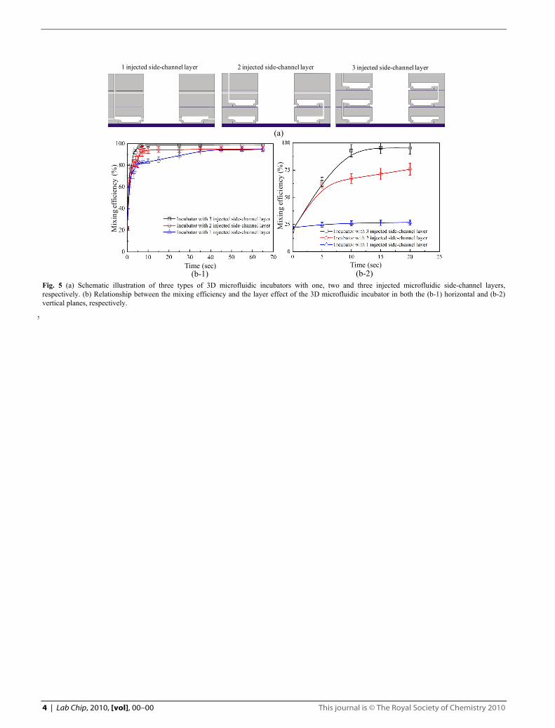
In order to rapidly mix a large amount of samples, three types 45
of 3D microfluidic incubators with one, two and three injected side-channel layers have been designed to explore their performance. Figure 5(a) schematically illustrates the three designs. Each of the microfluidic incubators are designed for handling 1mL of sample with the incorporation of the injected 50
side-channels to generate a swirling effect in the 3D incubation chamber. The mixing performance of the 3D microfluidic incubators are shown in Figure 5(b) in both horizontal and vertical views. A fixed amount of sample with the volume of 1 mL composed of 500 μL of red ink and 500 55
μL of DI water are loaded into the incubation chamber to verify the mixing efficiency by measuring the concentration profiles through the incubation chamber. The operating conditions are fd=1.5 Hz at an air pressure of -80 KPa. It is clearly observed that the sample can be well-mixed within 10s 60
by utilizing the 3D microfluidic incubator with 3-layers of injected side-channels in both the horizontal and vertical planes, respectively. The performance of 3-layer microfluidic incubator is superior to the other two designs due to its capability to generate a stronger swirling flow. Consequently, 65
the 3D microfluidic incubators with three injected side-channel layers has been employed in the prototype integrated microfluidic system and the capability to handle a large amount of sample in the 3D incubation chamber has also been demonstrated. 70
(a-1) t=0s (a-2) t=1s (a-3) t=2s
(a-4) t=3s (a-5) t=4s (a-6) t=5s
(b-1) t=0s (b-2) t=1s (b-3) t=2s
(b-4) t=3s (b-5) t=6s (b-6) t=10s Fig. 4 A sequence of time-lapse images of the red ink in the 3D incubation chamber in the (a) horizontal and (b) vertical panes. The fd is 1.5 Hz at an air pressure of -80 KPa.
4 | Lab Chip, 2010, [vol], 00–00 This journal is © The Royal Society of Chemistry 2010
Mix
ing
effic
ienc
y (%
)
Time (sec)
Mix
ing
effic
ienc
y (%
)
Time (sec)(b-1) (b-2)
1 injected side-channel layer 2 injected side-channel layer 3 injected side-channel layer
(a)
Fig. 5 (a) Schematic illustration of three types of 3D microfluidic incubators with one, two and three injected microfluidic side-channel layers, respectively. (b) Relationship between the mixing efficiency and the layer effect of the 3D microfluidic incubator in both the (b-1) horizontal and (b-2) vertical planes, respectively.
5