supplement no. 1 to aisc 358-16 prequalified … draft dated august 30, 2017 supplement no. 1 to...
TRANSCRIPT

1
Draft Dated August 30, 2017 Supplement No. 1 to Prequalified Connections for Special and Intermediate Steel Moment Frames for Seismic Applications
AMERICAN INSTITUTE OF STEEL CONSTRUCTION
DRAFT AISC 358-16s1 1
2
3
Supplement No. 1 4
to AISC 358-16 5
Prequalified Connections 6
for Special and Intermediate 7
Steel Moment Frames for 8
Seismic Applications 9
10
11 12
Draft Dated August 30, 2017 13 14 15 16
17
18
19
20
21
22
23
24
25
26
27
28
29
30
31 32
AMERICAN INSTITUTE OF STEEL CONSTRUCTION 33 130 East Randolph Street, Suite 2000 34
Chicago, Illinois 60601 35 36

2
Draft Dated August 30, 2017 Supplement No. 1 to Prequalified Connections for Special and Intermediate Steel Moment Frames for Seismic Applications
AMERICAN INSTITUTE OF STEEL CONSTRUCTION
AISC © 201X 37
38
by 39
40
American Institute of Steel Construction 41
42
All rights reserved. This book or any part thereof 43
must not be reproduced in any form without the 44
written permission of the publisher. 45
46
The AISC logo is a registered trademark of AISC. 47
48
The information presented in this publication has been prepared by a balanced committee following American 49 National Standards Institute (ANSI) consensus procedures and recognized principles of design and construction. 50 While it is believed to be accurate, this information should not be used or relied upon for any specific application 51 without competent professional examination and verification of its accuracy, suitability and applicability by a 52 licensed engineer or architect. The publication of this information is not a representation or warranty on the part of 53 the American Institute of Steel Construction, its officers, agents, employees or committee members, or of any other 54 person named herein, that this information is suitable for any general or particular use, or of freedom from 55 infringement of any patent or patents. All representations or warranties, express or implied, other than as stated 56 above, are specifically disclaimed. Anyone making use of the information presented in this publication assumes all 57 liability arising from such use. 58 59 Caution must be exercised when relying upon standards and guidelines developed by other bodies and incorporated 60 by reference herein since such material may be modified or amended from time to time subsequent to the printing of 61 this edition. The American Institute of Steel Construction bears no responsibility for such material other than to refer 62 to it and incorporate it by reference at the time of the initial publication of this edition. 63 64
Printed in the United States of America 65 66

3
Draft Dated August 30, 2017 Supplement No. 1 to Prequalified Connections for Special and Intermediate Steel Moment Frames for Seismic Applications
AMERICAN INSTITUTE OF STEEL CONSTRUCTION
67
Table of Contents 68
69 SYMBOLS ..................................................................................................................................................... 4 70
71
CHAPTER 11. SIDEPLATE MOMENT CONNECTION ....................................................................... 6 72
11.1. General ........................................................................................................................................ 6 73
11.2. Systems ..................................................................................................................................... 10 74
11.3. Prequalification Limits .............................................................................................................. 10 75
1. Beam Limitations ...................................................................................................................... 10 76
2. Column Limitations ................................................................................................................... 12 77
3. Connection Limitations ............................................................................................................. 14 78
11.4. Column-Beam Relationship Limitations ................................................................................... 14 79
11.5. Connection Welding Limitations .............................................................................................. 17 80
11.6. Connection Detailing ................................................................................................................. 18 81
1. Plates ......................................................................................................................................... 18 82
2. Welds ......................................................................................................................................... 18 83
3. Bolts .......................................................................................................................................... 23 84
11.7. Design Procedure ...................................................................................................................... 24 85
86
CHAPTER 14. SLOTTEDWEB MOMENT CONNECTION ................................................................ 28 87
88
14.1. General ...................................................................................................................................... 28 89
14.2. Systems ..................................................................................................................................... 29 90
14.3. Prequalification Limits .............................................................................................................. 29 91
1. Beam Limitations ............................................................................................................. 29 92
2. Column Limitations .......................................................................................................... 30 93
14.4. Column-Beam Relationship Limitations ................................................................................... 30 94
14.5. Beam Flange-to-Column Flange Weld Limitations .................................................................. 31 95
14.6. Beam Web and Shear Plate Connection Limitations ................................................................. 31 96
14.7. Fabrication of Beam Web Slots ................................................................................................. 32 97
14.8. Design Procedure ...................................................................................................................... 32 98
COMMENTARY ........................................................................................................................................ 36 99
REFERENCES ............................................................................................................................................ 62 100
101 102
4
Draft Dated August 30, 2017 Supplement No. 1 to Prequalified Connections for Special and Intermediate Steel Moment Frames for Seismic Applications
AMERICAN INSTITUTE OF STEEL CONSTRUCTION
SYMBOLS 103
104
This Standard uses the following symbols in addition to the terms defined in the Specification for Structural Steel 105
Buildings (ANSI/AISC 360-16) and the Seismic Provisions for Structural Steel Buildings (ANSI/AISC 341-16). 106
Some definitions in the following list have been simplified in the interest of brevity. In all cases, the definitions given 107
in the body of the Standard govern. Symbols without text definitions, used in only one location and defined at that 108
location, are omitted in some cases. The section or table number on the right refers to where the symbol is first used. 109
110
Symbol Definition Section 111
112
A Perpendicular amplified seismic drag or chord forces transferred through the 113
SidePlate connection, resulting from applicable building code, kips (N) .......................... 11.7 114
A|| In-plane factored lateral drag or chord axial forces transferred along the frame beam 115
through the SidePlate connection, resulting from load case 1.0EQ per applicable building 116
code, kips (N) .................................................................................................................... 11.7 117
Cpr Factor to account for peak connection strength, including strain 118
hardening, local restraint, additional reinforcement, and other 119
connection conditions ........................................................................................................ 14.8 120
Fye Expected yield strength of steel beam, ksi (MPa) .............................................................. 14.8 121
Fy Specified minimum yield stress of the yielding element, ksi (MPa) ................................. 14.8 122
Hh Distance along column height from ¼ of the column depth above the top edge of the lower-123
story side plates to ¼ of the column depth below the bottom edge of the upper-story side 124
plates, in. (mm) .................................................................................................................. 11.4 125
Ibeam Moment of inertia of the beam in the plane of bending, in.4 (mm4) .................... Figure 11.16 126
Itotal Approximation of moment of inertia due to beam hinge location and side plate stiffness, 127
in.4 (mm4) ............................................................................................................ Figure 11.16 128
Mcant Factored gravity moments from cantilever beams that are not in the plane of the moment 129
frame but are connected to the exterior face of the side plates, resulting from code-130
applicable load combinations, kip-in. (N-mm). ................................................................. 11.7 131
Mf Probable maximum moment at face of the column, kip-in. (N-mm) ................................. 14.8 132
Mgroup Maximum probable moment demand at any connection element, kip-in. (N-mm) ........... 11.7 133
Mpr Probable maximum moment at the plastic hinge, kip-in. (N-mm) ................................... 14.4 134
M*pb Projection of the expected flexural strength of the beam as defined in the AISC Seismic 135
Provisions, kip-in. (N-mm)................................................................................................ 14.4 136
Muv Additional moment due to shear amplification from the plastic hinge, kip-in. (N-mm).... 14.4 137
Mweld Moment resisted by the shear plate, kip-in. (N-mm) ......................................................... 14.8 138
Ry Ratio of the expected yield stress to the specified minimum yield stress, Fy, as specified in 139
the AISC Seismic Provisions ............................................................................................ 14.8 140
T Beam web height as given in the AISC Manual, in. (mm) ................................................ 14.8 141
Vbeam Shear at beam plastic hinge, kips (N) ................................................................................ 14.4 142
5
Draft Dated August 30, 2017 Supplement No. 1 to Prequalified Connections for Special and Intermediate Steel Moment Frames for Seismic Applications
AMERICAN INSTITUTE OF STEEL CONSTRUCTION
Vcant Factored gravity shear forces from cantilever beams that are not in the plane of the moment 143
frame but are connected to the exterior face of the side plates, resulting from code-144
applicable load combinations, kips (N) ............................................................................. 11.7 145
Vgravity Beam shear force resulting from the load combination 1.2D + f1L + 0.2S, kips (N) ......... 14.8 146
Vweld Shear resisted by the shear plate, kips (N) ......................................................................... 14.8 147
V1 , V2 Factored gravity shear forces from gravity beams that are not in the plane of the moment 148
frame but are connected to the exterior surfaces of the side plate, resulting from the load 149
combination of 1.2D + f1L + 0.2S (where f1 is the load factor determined by the applicable 150
building code for live loads, but not less than 0.5), kips (N) ............................................. 11.7 151
Zbeam Plastic section modulus of the beam, in.3 (mm3) ............................................................... 14.8 152
Zec Equivalent plastic section modulus of the column at a distance of ¼ the column depth 153
from the top and bottom edge of the side plates, projected to the beam centerline, 154
in.3 (mm3) ......................................................................................................................... 11.4 155
Zweb Plastic section modulus of the beam web, in.3 (mm3) ........................................................ 14.8 156
Zxb Plastic modulus of beam about the x-axis, in.3 (mm3) ....................................................... 11.7 157
Zxc Plastic modulus of column about the x-axis, in.3 (mm3) .................................................... 11.7 158
bf Flange width, in. (mm) ...................................................................................................... 14.8 159
d Nominal beam depth, in. (mm) .......................................................................................... 14.8 160
dcol Depth of the column, in. (mm) .......................................................................................... 14.4 161
dc1, dc2 Depth of column on each side of a bay in a moment frame, in. (mm) ............................... 11.3 162
ex Eccentricity of the shear plate weld, in. (mm) ................................................................... 14.8 163
h Height of shear plate, in. (mm) .......................................................................................... 14.8 164
lb Half the clear span length of beam, in. (mm) .................................................................... 14.8 165
lp Width of shear plate, in. (mm) ........................................................................................... 14.4 166
ls Beam slot length, in. (mm) ................................................................................................ 14.8 167
tbf Thickness of beam flange, in. (mm) .................................................................................. 14.8 168
tp Minimum required shear plate thickness, in. (mm) ........................................................... 14.8 169
tbw Thickness of beam web, in. (mm) ..................................................................................... 14.8 170
x Distance from plastic hinge location to centroid of connection element, 171
in. (mm) ............................................................................................................................. 11.7172

6
Draft Dated August 30, 2017 Supplement No. 1 to Prequalified Connections for Special and Intermediate Steel Moment Frames for Seismic Applications
AMERICAN INSTITUTE OF STEEL CONSTRUCTION
CHAPTER 11 173
SIDEPLATE MOMENT CONNECTION 174
175 The user’s attention is called to the fact that compliance with this chapter of the standard requires 176 use of an invention covered by multiple U.S. and foreign patent rights.* By publication of this 177 standard, no position is taken with respect to the validity of any claim(s) or of any patent rights in 178 connection therewith. The patent holder has filed a statement of willingness to grant a license 179 under these rights on reasonable and nondiscriminatory terms and conditions to applicants 180 desiring to obtain such a license, and the statement may be obtained from the standard’s developer. 181
11.1. GENERAL 182
The SidePlate® moment connection utilizes interconnecting plates to connect beams 183 to columns. The connection features a physical separation, or gap, between the face 184 of the column flange and the end of the beam. Both field-welded and field-bolted 185 options are available. Beams may be either rolled or built-up wide-flange sections or 186 hollow structural sections (HSS). Columns may be either rolled or built-up wide-187 flange sections, built-up box column sections or HSS for uniaxial configurations. 188 Built-up flanged cruciform sections consisting of rolled shapes or built-up from plates 189 may also be used as the columns for biaxial configurations. Figures 11.1, 11.2, and 190 11.3 show the various field-welded and field-bolted uniaxial connection 191 configurations. The field bolted option is available in two configurations, referred to 192 as Config. A (Standard) and Config. B (Narrow), as shown in Figure 11.3. 193
194 In the field-welded connection, top and bottom beam flange cover plates (rectangular 195 or U-shaped) are used at the end(s) of the beam, as applicable, which also serve to 196 bridge any difference between flange widths of the beam(s) and of the column. The 197 connection of the beam to the column is accomplished with parallel full-depth side 198 plates that sandwich and connect the beam(s) and the column together. In the field-199 bolted connection, beam flanges are connected to the side plates with either a cover 200 plate or pair of angles and high strength pretensioned bolts as shown in Figures 11.2 201 and 11.3. Column horizontal shear plates and beam vertical shear elements (or shear 202 plates as applicable) are attached to the wide-flange shape column and beam webs, 203 respectively. 204
205
206
207
* The SidePlate® connection configurations and structures illustrated herein, including their described fabrication and erection methodologies, are protected by one or more of the following U.S. and foreign patents: U.S. Pat. Nos. 5,660,017; 6,138,427; 6,516,583; 6,591,573; 7,178,296; 8,122,671; 8,122,672; 8,146,322; 8,176,706; 8,205,408; Mexico Pat. No. 208,750; New Zealand Pat. No. 300,351; British Pat. No. 2497635; all held by MiTek Holdings LLC. Other U.S. and foreign patent protection are pending.

7
Draft Dated August 30, 2017 Supplement No. 1 to Prequalified Connections for Special and Intermediate Steel Moment Frames for Seismic Applications
AMERICAN INSTITUTE OF STEEL CONSTRUCTION
(a) (b) (c)
(d) (e) (f)
Fig. 11.1. Assembled SidePlate uniaxial field-welded configurations: (a) one-sided wide-flange 208 beam and column construction;(b) two-sided wide-flange beam and column construction; (c) 209 wide-flange beam to either HSS or built-up box column; (d) HSS beam without cover plates to 210 wide-flange column; (e) HSS beam with cover plates to wide-flange column; and (f) HSS beam 211
with cover plates to either HSS or built-up box column. 212
213
214 (a) (b) (c)
215 (d) (e) (f)
Fig. 11.2. Assembled SidePlate uniaxial field-bolted Standard configurations (Config. A): (a) 216 one-sided wide-flange beam and column construction; (b) two-sided wide-flange beam and 217
column construction; (c) wide-flange beam to either HSS or built-up box column; (d) HSS beam 218 to wide-flange column; (e) HSS beam with cover plate to wide-flange column; and (f) HSS beam 219
with cover plates to either HSS or built-up box column. 220
8
Draft Dated August 30, 2017 Supplement No. 1 to Prequalified Connections for Special and Intermediate Steel Moment Frames for Seismic Applications
AMERICAN INSTITUTE OF STEEL CONSTRUCTION
221
(a) (b) (c)
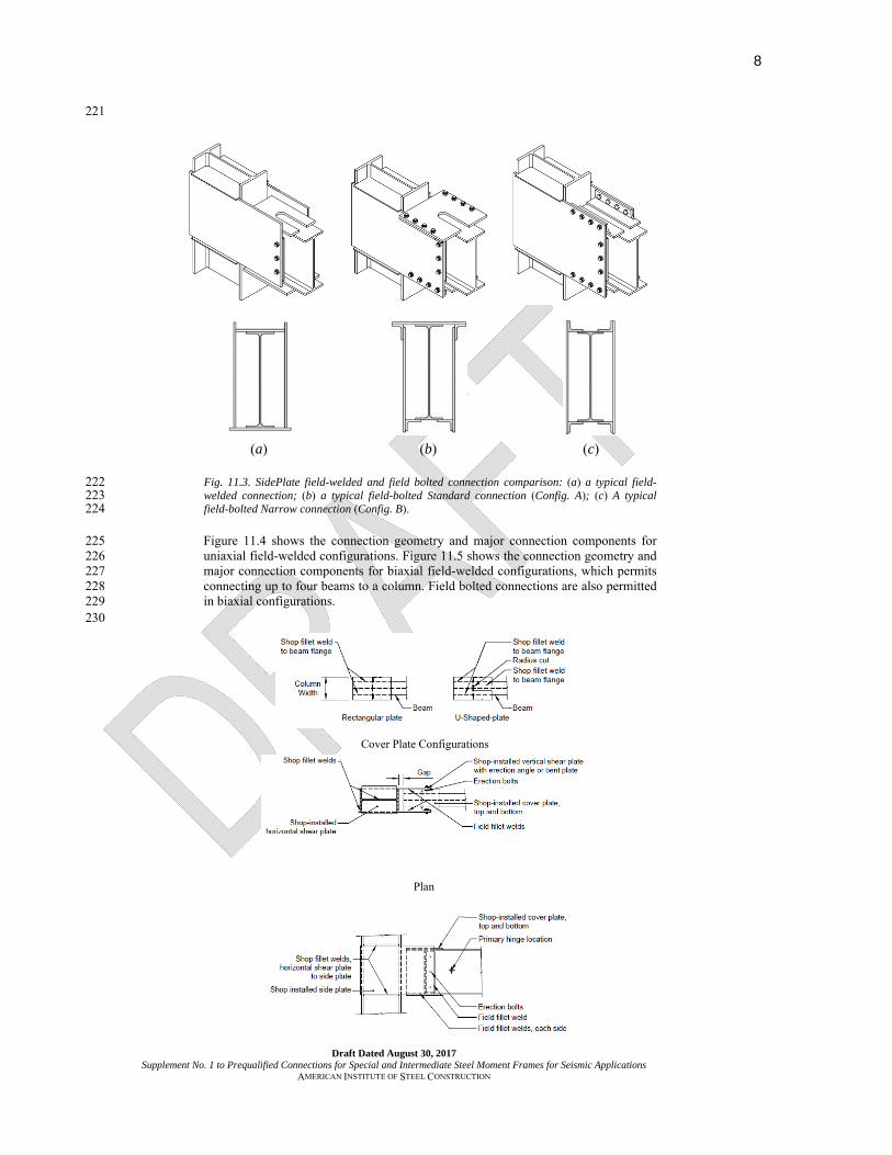
Fig. 11.3. SidePlate field-welded and field bolted connection comparison: (a) a typical field-222 welded connection; (b) a typical field-bolted Standard connection (Config. A); (c) A typical 223 field-bolted Narrow connection (Config. B). 224
Figure 11.4 shows the connection geometry and major connection components for 225 uniaxial field-welded configurations. Figure 11.5 shows the connection geometry and 226 major connection components for biaxial field-welded configurations, which permits 227 connecting up to four beams to a column. Field bolted connections are also permitted 228 in biaxial configurations. 229
230
Cover Plate Configurations
Plan

9
Draft Dated August 30, 2017 Supplement No. 1 to Prequalified Connections for Special and Intermediate Steel Moment Frames for Seismic Applications
AMERICAN INSTITUTE OF STEEL CONSTRUCTION
Elevation
(a)
(b)
(c)
(d)
Fig. 11.4. SidePlate uniaxial configuration geometry and major components: (a) typical wide-231 flange beam to wide-flange column, detail, plan and elevation views; (b) HSS beam without 232
cover plates to wide-flange column, plan view; (c) HSS beam with cover plates to wide-flange 233 column, plan view; and (d) wide-flange beam to built-up box column, plan view. 234
235
(a) (b)

10
Draft Dated August 30, 2017 Supplement No. 1 to Prequalified Connections for Special and Intermediate Steel Moment Frames for Seismic Applications
AMERICAN INSTITUTE OF STEEL CONSTRUCTION
236
Fig. 11.5. SidePlate biaxial dual-strong axis configurations in plan view: (a) full four-sided 237 wide-flange column configuration; (b) corner two-sided wide-flange column configuration with 238 single WT; (c) tee three-sided wide-flange column configuration with double WT (primary); and 239
(d) tee three-sided wide-flange column configuration with single WT. 240
The SidePlate moment connection is proportioned to develop the probable maximum 241 moment capacity of the connected beam. Plastic hinge formation is intended to occur 242 primarily in the beam beyond the end of the side plates away from the column face, 243 with limited yielding occurring in some of the connection elements. 244
User Note: Moment frames that utilize the SidePlate connection can be constructed 245 using one of three methods. These are the full-length beam erection method 246 (SidePlate FRAME configuration), the link-beam erection method (SidePlate Original 247 configuration), and the fully shop prefabricated method. These methods are described 248 in the commentary. 249
250
11.2. SYSTEMS 251
The SidePlate moment connection is prequalified for use in special moment frame 252 (SMF) and intermediate moment frame (IMF) systems within the limits of these 253 provisions. The SidePlate moment connections are prequalified for use in planar 254 moment-resisting frames and orthogonal intersecting moment-resisting frames 255 (biaxial configurations, capable of connecting up to four beams at a column), as 256 illustrated in Figure 11.5. 257
11.3. PREQUALIFICATION LIMITS 258
1. Beam Limitations 259
Beams shall satisfy the following limitations: 260
261 (1) Beams shall be rolled wide-flange, hollow structural section (HSS), or built-up I-262
shaped beams conforming to the requirements of Section 2.3. Beam flange 263 thickness shall be limited to a maximum of 2.5 in. (63 mm). 264
(2) Rolled and built-up wide-flange beam depth shall be limited to W40 (W1000) 265 and W44 (W1100) for the field-welded and field-bolted connections, 266 respectively. 267
(3) Beam depths shall be limited as follows for HSS shapes: 268
(a) For SMF systems, HSS14 (HSS 356) or smaller. 269
(c) (d)

11
Draft Dated August 30, 2017 Supplement No. 1 to Prequalified Connections for Special and Intermediate Steel Moment Frames for Seismic Applications
AMERICAN INSTITUTE OF STEEL CONSTRUCTION
(b) For IMF systems, HSS16 (HSS 406) or smaller. 270
(4) Rolled and built-up wide-flange beam weight shall be limited to 302 lb/ft (449 271 kg/m) and 400 lb/ft (595 kg/m) for the field-welded and field-bolted 272 connections, respectively. Beam flange area of the field-bolted connection shall 273 be limited to a maximum of 36 in.² (22900 mm2) 274
(5) The ratio of the hinge-to-hinge span of the beam, Lh, to beam depth, d, shall be 275 limited as follows: 276
(a) For SMF systems, Lh/d is limited to: 277
6 or greater with rectangular shaped cover plates. 278
4.5 or greater with U-shaped cover plates for field-welded 279 connections. 280
4.0 or greater with U-shaped cover plates for field-bolted connections. 281
(b) For IMF systems, Lh/d is limited to 3 or greater. 282
The hinge-to-hinge span of the beam, Lh, is the distance between the locations of 283 plastic hinge formation at each moment-connected end of that beam. The 284 location of plastic hinge shall be taken as one-third of the beam depth, d/3 for the 285 field-welded connection and one-sixth of the beam depth, d/6, for the field-286 bolted connection, away from the end of the side-plate extension, as shown in 287 Figure 11.6. Thus, 288
Lh = L – ½(dc1 + dc2) – 2(0.33)d – 2A (field-welded) (11.3-1a) 289
Lh = L – ½(dc1 + dc2) – 2(0.165)d – 2A (field-bolted) (11.3-1b) 290
where 291
L = distance between column centerlines, in. (mm) 292
dc1, dc2 = depth of column on each side of a bay in a moment frame, in. 293 (mm) 294
User Note: The 0.33d and 0.165d constants represent the distance of the 295 plastic hinge from the end of the side plate extension. A represents the typical 296 extension of the side plates from the face of column flange. 297
(6) Width-to-thickness ratios for beam flanges and webs shall conform to the limits of 298 the AISC Seismic Provisions. 299
(7) Lateral bracing of wide-flange beams shall be provided in conformance with the 300 AISC Seismic Provisions. Lateral bracing of HSS beams shall be provided in 301 conformance with Appendix 1, Section 1.3.2c of the AISC Specification, 302
taking 1 2 1M M in AISC Specification Equation A-1-7. For either wide-flange 303
or HSS beams, the segment of the beam connected to the side plates shall be 304 considered to be braced. Supplemental top and bottom beam flange bracing at the 305 expected hinge is not required. 306

12
Draft Dated August 30, 2017 Supplement No. 1 to Prequalified Connections for Special and Intermediate Steel Moment Frames for Seismic Applications
AMERICAN INSTITUTE OF STEEL CONSTRUCTION
(8) The protected zone in the beam for the field-welded and field-bolted connections 307 shall consist of the portion of the beam as shown in Figure 11.7 and Figure 11.8, 308 respectively. 309
310
Fig. 11.6. Plastic hinge location and hinge-to-hinge length. 311
2. Column Limitations 312
Columns shall satisfy the following limitations: 313
(1) Columns shall be any of the rolled shapes, hollow structural section (HSS), built-314 up I-shaped sections, flanged cruciform sections consisting of rolled shapes or 315 built-up from plates or built-up box sections meeting the requirements of Section 316 2.3. Flange and web plates of built up box columns may continuously be 317 connected by fillet welds or PJP groove welds along the length of the column. 318
(2) HSS column shapes must conform to ASTM A1085. 319
(3) The beam shall be connected to the side plates that are connected to the flange 320 tips of the wide-flange or corners of HSS or box columns. 321
(4) Rolled shape column depth shall be limited to W44 (W1100). The depth of built-322 up wide-flange columns shall not exceed that for rolled shapes. Flanged 323 cruciform columns shall not have a width or depth greater than the depth 324 allowed for rolled shapes. Built-up box columns shall not have a width 325 exceeding 33 in. (840 mm). 326
(5) There is no limit on column weight per foot. 327
(6) There are no additional requirements for column flange thickness. 328
(7) Width-to-thickness ratios for the flanges and webs of columns shall conform to 329 the requirements of the AISC Seismic Provisions. 330
(8) Lateral bracing of columns shall conform to the requirements of the AISC 331 Seismic Provisions. 332
333

13
Draft Dated August 30, 2017 Supplement No. 1 to Prequalified Connections for Special and Intermediate Steel Moment Frames for Seismic Applications
AMERICAN INSTITUTE OF STEEL CONSTRUCTION
334
335
336
(a) 337 338
339
340
(b) 341
Fig. 11.7. Location of beam and side plate protected zones for the field-welded connection: (a) 342 one-sided connection; (b) two-sided connection 343
344
345
346
(a) 347

14
Draft Dated August 30, 2017 Supplement No. 1 to Prequalified Connections for Special and Intermediate Steel Moment Frames for Seismic Applications
AMERICAN INSTITUTE OF STEEL CONSTRUCTION
348
349
(b) 350
Fig. 11.8. Location of beam protected zone for the field-bolted connection: (a) one-sided 351 connection; (b) two-sided connection 352
353
3. Connection Limitations 354
The connection shall satisfy the following limitations: 355
(1) All connection steel plates, which consist of side plates, cover plates, horizontal 356 shear plates, and vertical shear elements, must be fabricated from structural steel 357 that complies with ASTM A572/A572M Grade 50 (Grade 345). 358
Exception: The vertical shear element as defined in Section 11.6 may be 359 fabricated using ASTM A36/A36M material. 360
(2) The extension of the side plates beyond the face of the column shall be within 361 the range of 0.65d to 1.0d and 0.65d to 1.7d, for the field-welded and field-362 bolted connections, respectively, where d is the nominal depth of the beam. 363
(3) The protected zone of the connection in the side plates shall consist of a portion 364 of each side plate that is 6 in. (150 mm) high and starts at the inside face of the 365 flange of a wide-flange or HSS column and ends either at the end of the gap 366 (field-welded connection) or the edge of the 1st bolt hole (field bolted 367 connection) as shown in Figures 11.7 and 11.8. 368
11.4. COLUMN-BEAM RELATIONSHIP LIMITATIONS 369
Beam-to-column connections shall satisfy the following limitations: 370
(1) Beam flange width and thickness for rolled, built-up and HSS shapes shall 371 satisfy the following equations for geometric compatibility (see Figure 11.9): 372
(a) Field-welded Connection 373
bbf + 1.1tbf + 1/2 in. ≤ bcf (11.4-1a) 374
bbf + 1.1tbf + 12 mm ≤ bcf (11.4-1aM) 375
(b) Field-bolted Connection 376
bbf + 1.0 in. ≤ bcf (11.4-1b) 377

15
Draft Dated August 30, 2017 Supplement No. 1 to Prequalified Connections for Special and Intermediate Steel Moment Frames for Seismic Applications
AMERICAN INSTITUTE OF STEEL CONSTRUCTION
bbf + 25 mm ≤ bcf (11.4-1bM) 378
379
where 380 bbf = width of beam flange, in. (mm) 381 bcf = width of column flange, in. (mm) 382 tbf = thickness of beam flange, in. (mm) 383
384
(a) (b) (c)
Fig. 11.9. Geometric compatibility (a) Field-welded connection; (b) Field-bolted Standard 385 connection (Config. A), (c) Field-bolted Narrow connection (Config. B) 386
(2) Panel zones shall conform to the applicable requirements of the AISC Seismic 387 Provisions. 388
User Note: The column web panel zone strength shall be determined by 389 Section J10.6a of the AISC Specification. 390
(3) Column-beam moment ratios shall be limited as follows: 391
(a) For SMF systems, the column-beam moment ratio shall conform to the 392 requirements of the AISC Seismic Provisions as follows: 393
(i) The value of ∑M*pb shall be the sum of the projections of the 394
expected flexural strengths of the beam(s) at the plastic hinge 395
locations to the column centerline (Figure 11.10). The expected 396
flexural strength of the beam shall be computed as: 397
∑M*pb = ∑(1.1RyFybZb + Mv) (11.4-2) 398
where 399
Fyb = specified minimum yield stress of beam, ksi (MPa) 400
Mv = additional moment due to shear amplification from the 401 center of the plastic hinge to the centerline of the 402 column. Mv shall be computed as the quantity Vhsh; 403 where Vh is the shear at the point of theoretical plastic 404

16
Draft Dated August 30, 2017 Supplement No. 1 to Prequalified Connections for Special and Intermediate Steel Moment Frames for Seismic Applications
AMERICAN INSTITUTE OF STEEL CONSTRUCTION
hinging, computed in accordance with Equation 11.4-405 3, and sh is the distance of the assumed point of plastic 406 hinging to the column centerline, which is equal to 407 half the depth of the column plus the extension of the 408 side plates beyond the face of column plus the 409 distance from the end of the side plates to the plastic 410 hinge, d/3. 411
2 pr
h gravityh
MV V
L (11.4-3) 412
where 413 Lh = distance between plastic hinge locations, 414
in. (mm) 415 Mpr = probable maximum moment at plastic 416
hinge, kip-in. (N-mm) 417 Vgravity = beam shear force resulting from 1.2D + 418
f1L + 0.2S (where f1 is the load factor 419 determined by the applicable building 420 code for live loads, but not less than 0.5), 421 kips (N) 422
Ry = ratio of expected yield stress to specified minimum 423
yield stress Fy as specified in the AISC Seismic 424
Provisions 425
Zb = nominal plastic section modulus of beam, in.3 (mm3) 426
User Note: The load combination of 1.2D + f1L + 427 0.2S is in conformance with ASCE/SEI 7-16. When 428 using the International Building Code, a factor of 0.7 429 must be used in lieu of the factor of 0.2 for S (snow) 430 when the roof configuration is such that it does not 431 shed snow off the structure. 432
(ii) The value of ∑M*pc shall be the sum of the projections of the nominal 433
flexural strengths (Mpc) of the column above and below the 434 connection joint, at the location of theoretical hinge formation in the 435 column (i.e., one quarter the column depth above and below the 436 extreme fibers of the side plates), to the beam centerline, with a 437 reduction for the axial force in the column (Figure 11.10). The 438 nominal flexural strength of the column shall be computed as: 439
*pc ec yc uc gM Z F P A (11.4-4) 440
where 441 Fyc = the minimum specified yield strength of the column at the 442
connection, ksi (MPa) 443 H = story height, in. (mm) 444 Hh = distance along column height from ¼ of column depth 445
above top edge of lower story side plates to ¼ of column 446 depth below bottom edge of upper story side plates, in. 447 (mm) 448
Puc/Ag = ratio of column axial compressive load, computed in 449 accordance with load and resistance factor provisions, to 450 gross area of the column, ksi (MPa) 451
Zc = plastic section modulus of column, in.3 (mm3) 452 Zec= the equivalent plastic section modulus of column (Zc) at a 453
distance of ¼ column depth from top and bottom edge of 454 side plates, projected to beam centerline, in.3 (mm3), and 455 computed as: 456
457

17
Draft Dated August 30, 2017 Supplement No. 1 to Prequalified Connections for Special and Intermediate Steel Moment Frames for Seismic Applications
AMERICAN INSTITUTE OF STEEL CONSTRUCTION
2
2c c
ech h
Z H Z HZ
H H
(11.4-5) 458 459
(b) For IMF systems, the column-beam moment ratio shall conform to the 460 requirements of the AISC Seismic Provisions. 461
Fig. 11.10. Force and distance designations for computation of column-beam moment ratios. 462
11.5. CONNECTION WELDING LIMITATIONS 463
Filler metals for the welding of beams, columns and plates in the SidePlate 464 connection shall meet the requirements for seismic force-resisting system welds in the 465 AISC Seismic Provisions. 466
User Note: Mechanical properties for filler metals for seismic force-resisting system 467 welds are detailed in AWS D1.8/D1.8M as referenced in the AISC Seismic 468 Provisions. 469
The following welds are considered demand critical welds: 470
(1) Shop fillet weld 2 that connects the inside face of the side plates to the wide-471 flange or HSS columns (see plan views in Figure 11.11, Figure 11.12 and Figure 472 11.13) and for biaxial dual-strong axis configurations connects the outside face 473 of the secondary side plates to the outside face of primary side plates (see Figure 474 11.5). 475
(2) Shop fillet weld 5 that connects the edge of the beam flange to the beam 476 flange cover plate or angles (see Figures 11.14a and 11.14b). 477
(3) Shop fillet weld 5a that connects the outside face of the beam flange to the 478 beam flange U-shaped cover plate or angles (see Figures 11.14a and 11.14b). 479
(4) Field fillet weld 7 that connects the beam flange cover plates to the side plates 480 (see Figure 11.15a), or connects the HSS beam flange to the side plates. 481
(5) Fillet weld 8 that connects the top angles to the side plates in the field-bolted 482 connection. 483

18
Draft Dated August 30, 2017 Supplement No. 1 to Prequalified Connections for Special and Intermediate Steel Moment Frames for Seismic Applications
AMERICAN INSTITUTE OF STEEL CONSTRUCTION
11.6. CONNECTION DETAILING 484
The following designations are used herein to identify plates and welds in the 485 SidePlate connection shown in Figures 1111 through 11.15: 486
1. Plates/Angles 487
A Side plate, located in a vertical plane parallel to the web(s) of the beam, 488 connecting frame beam to column. 489
B Beam flange cover plate bridging between side plates A, as applicable. 490
C Vertical shear plate. 491
D Horizontal shear plate (HSP). This element transfers horizontal shear from the 492 top and bottom edges of the side plates A to the web of a wide-flange column. 493
E Erection angle. One of the possible vertical shear elements F. 494
F Vertical shear elements (VSE). These elements, which may consist of angles and 495 plates or bent plates, transfer shear from the beam web to the outboard edge of 496 the side plates A. 497
G Longitudinal angles welded to the side plates A for connecting the beam 498 flange cover plate (field-bolted connection). 499
H Longitudinal angles welded to the beam flange for connecting to the side plates 500 A (field-bolted connection). 501
T Horizontal plates welded to the side plates A for connecting the beam flange 502 cover plate as an alternative for Angle G (field-bolted connection). 503
2. Welds 504
1 Shop fillet weld connecting exterior edge of side plate A to the horizontal shear 505 plate D or to the face of a built-up box column or HSS section. 506
2 Shop fillet weld connecting inside face of side plate A to the tip of the column 507 flange, or to the corner of an HSS or built-up column section; and for biaxial dual-508 strong axis configurations connects outside face of secondary side plates to 509 outside face of primary side plates. 510
3 Shop fillet weld connecting horizontal shear plate D to wide-flange column web. 511 Weld 3 is also used at the column flanges where required to resist orthogonal 512 loads through the connection due to collectors, chords or cantilevers. 513
4 Shop fillet weld connecting vertical shear elements F to the beam web, and where 514 applicable, the vertical shear plate C to the erection angle E. 515
5 Shop fillet weld connecting beam flange tip to cover plate B/angles H. 516
5a Shop weld connecting outside face of beam flange to cover plate B (or to the face 517 of the beam flange with the angles H). 518
6 Field vertical fillet weld connecting vertical shear element (angle or bent plate) F 519 to end of side plate A (field-welded connection). 520
7 Field horizontal fillet weld connecting the cover plate B to the side plate A, or 521 connects HSS beam corners to side plates (field-welded connection). 522
19
Draft Dated August 30, 2017 Supplement No. 1 to Prequalified Connections for Special and Intermediate Steel Moment Frames for Seismic Applications
AMERICAN INSTITUTE OF STEEL CONSTRUCTION
8 Shop weld connecting the longitudinal angles G or horizontal plate T to the 523 side plate A (field-bolted connection). 524
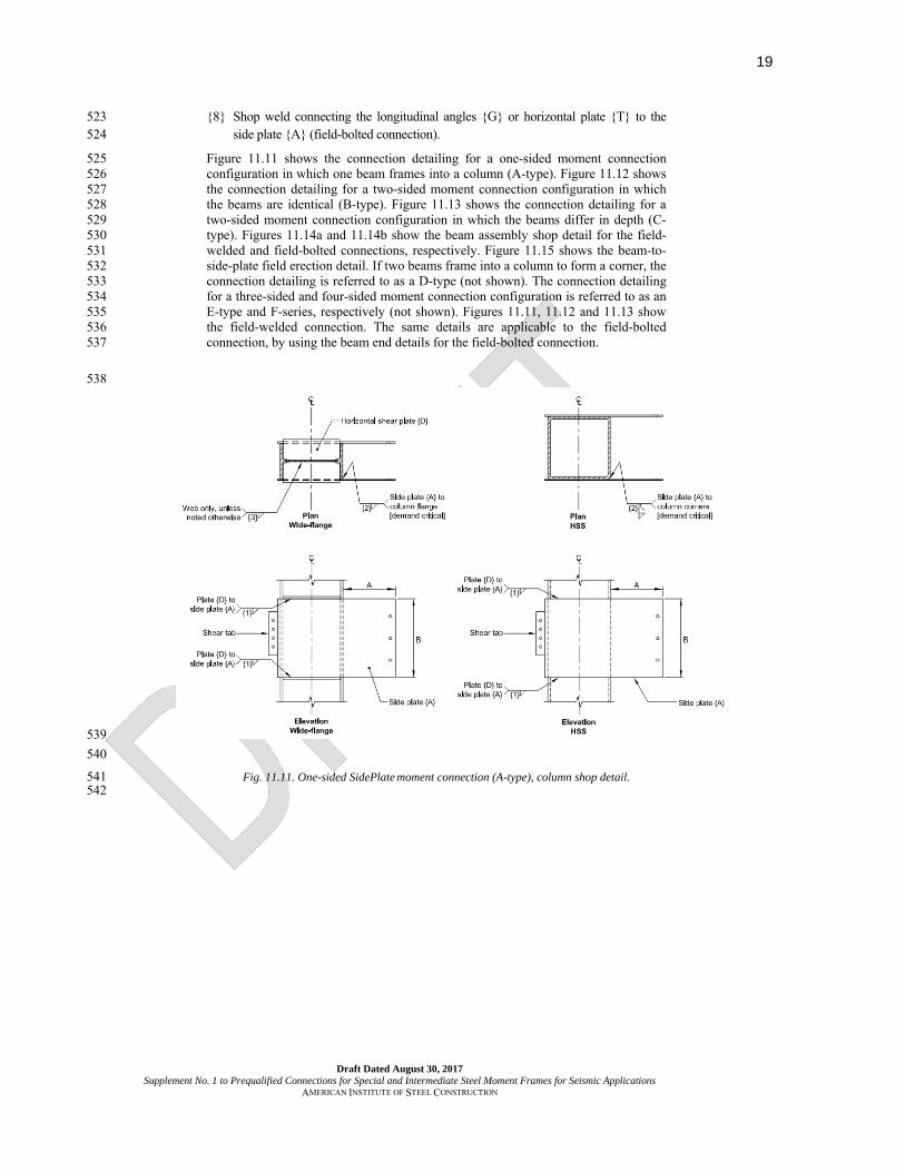
Figure 11.11 shows the connection detailing for a one-sided moment connection 525 configuration in which one beam frames into a column (A-type). Figure 11.12 shows 526 the connection detailing for a two-sided moment connection configuration in which 527 the beams are identical (B-type). Figure 11.13 shows the connection detailing for a 528 two-sided moment connection configuration in which the beams differ in depth (C-529 type). Figures 11.14a and 11.14b show the beam assembly shop detail for the field-530 welded and field-bolted connections, respectively. Figure 11.15 shows the beam-to-531 side-plate field erection detail. If two beams frame into a column to form a corner, the 532 connection detailing is referred to as a D-type (not shown). The connection detailing 533 for a three-sided and four-sided moment connection configuration is referred to as an 534 E-type and F-series, respectively (not shown). Figures 11.11, 11.12 and 11.13 show 535 the field-welded connection. The same details are applicable to the field-bolted 536 connection, by using the beam end details for the field-bolted connection. 537
538
539
540
Fig. 11.11. One-sided SidePlate moment connection (A-type), column shop detail. 541 542

20
Draft Dated August 30, 2017 Supplement No. 1 to Prequalified Connections for Special and Intermediate Steel Moment Frames for Seismic Applications
AMERICAN INSTITUTE OF STEEL CONSTRUCTION
543
544 Fig. 11.12. Two-sided SidePlate moment connection (B-type), column shop detail. 545
546

21
Draft Dated August 30, 2017 Supplement No. 1 to Prequalified Connections for Special and Intermediate Steel Moment Frames for Seismic Applications
AMERICAN INSTITUTE OF STEEL CONSTRUCTION
547
548 Fig. 11.13. Two-sided SidePlate moment connection (C-type), column shop detail. 549
550
551
Fig. 11.14a. Beam shop detail (field-welded). 552

22
Draft Dated August 30, 2017 Supplement No. 1 to Prequalified Connections for Special and Intermediate Steel Moment Frames for Seismic Applications
AMERICAN INSTITUTE OF STEEL CONSTRUCTION
553
554
Fig. 11.14b. Beam shop detail, field-bolted Standard (Config. A) 555
556
23
Draft Dated August 30, 2017 Supplement No. 1 to Prequalified Connections for Special and Intermediate Steel Moment Frames for Seismic Applications
AMERICAN INSTITUTE OF STEEL CONSTRUCTION
(a)
(b)
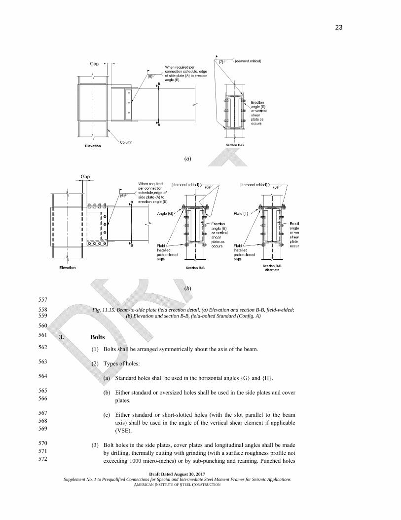
557
Fig. 11.15. Beam-to-side plate field erection detail. (a) Elevation and section B-B, field-welded; 558 (b) Elevation and section B-B, field-bolted Standard (Config. A) 559
560
3. Bolts 561
(1) Bolts shall be arranged symmetrically about the axis of the beam. 562
(2) Types of holes: 563
(a) Standard holes shall be used in the horizontal angles G and H. 564
(b) Either standard or oversized holes shall be used in the side plates and cover 565
plates. 566
(c) Either standard or short-slotted holes (with the slot parallel to the beam 567
axis) shall be used in the angle of the vertical shear element if applicable 568
(VSE). 569
(3) Bolt holes in the side plates, cover plates and longitudinal angles shall be made 570
by drilling, thermally cutting with grinding (with a surface roughness profile not 571
exceeding 1000 micro-inches) or by sub-punching and reaming. Punched holes 572

24
Draft Dated August 30, 2017 Supplement No. 1 to Prequalified Connections for Special and Intermediate Steel Moment Frames for Seismic Applications
AMERICAN INSTITUTE OF STEEL CONSTRUCTION
are not permitted. 573
(4) All bolts shall be installed as pretensioned high-strength bolts. 574
(5) Bolts shall be pretensioned high-strength bolts conforming to ASTM F3125 575
grade A490 or A490M or ASTM F2280. Bolt diameter is limited to 1-1/2 in. (38 576
mm) maximum. 577
(6) The use of shim plates between the side plates and the cover plate or angles is 578 permitted at either or both locations, subject to the limitations of RCSC 579 Specification. 580
(7) Faying surfaces of side plates, cover plate and angles shall have a Class A slip 581 coefficient or higher. 582
User Note: The use of oversized holes in the side plates and cover plates with 583
pretensioned bolts that are not designed as slip critical is permitted, consistent 584
with Section D2.2 of the Seismic Provisions. Although standard holes are 585
permitted in the side plate and cover plate, their use may result in field 586
modifications to accommodate erection tolerances. 587
588
11.7. DESIGN PROCEDURE 589
Step 1. Choose trial frame beam and column section combinations that satisfy 590 geometric compatibility based on Equation 11.4-1 or 11.4-1M. For SMF systems, 591 check that the section combinations satisfy the preliminary column-beam moment 592 ratio given by: 593
∑ (FycZxc) > 1.7 ∑ (FybZxb) (11.7-1) 594
where 595 Fyb =specified minimum yield stress of beam, ksi (MPa) 596 Fyc = specified minimum yield stress of column, ksi (MPa) 597 Zxb = plastic section modulus of beam, in.3 (mm3) 598 Zxc = plastic section modulus of column, in.3 (mm3) 599
Step 2. Approximate the effects on global frame performance of the increase in 600 lateral stiffness and strength of the SidePlate moment connection, due to beam hinge 601 location and side plate stiffening, in the mathematical elastic steel frame computer 602 model by using 100% rigid offset in the panel zone, and by increasing the moment of 603 inertia, elastic section modulus and plastic section modulus of the beam to 604 approximately three times that of the beam, for a distance of approximately 77% of 605 the beam depth beyond the column face (approximately equal to the extension of the 606 side plate beyond the face of the column), illustrated in Figure 11.16. 607
SMF beams that have a combination of shallow depth and heavy weight (i.e., beams 608 with a relatively large flange area such as those found in the widest flange series of a 609 particular nominal beam depth) require that the extension of the side plate A be 610 increased, up to the nominal depth of the beam, d and 1.7d, for the field-welded and 611 field-bolted connections respectively. 612
User Note: This increase in extension of side plate A of the field-welded 613 connection, lengthens fillet weld 7, thus limiting the extremes in the size of fillet 614 weld 7. Regardless of the extension of the side plate A, the plastic hinge occurs 615 at a distance of d/3 and d/6 from the end of the side plates for the field-welded and 616 field bolted connections, respectively. 617
Step 3. Confirm that the frame beams and columns satisfy all applicable building 618 code requirements, including, but not limited to, stress or strength checks and design 619 story drift checks. 620

25
Draft Dated August 30, 2017 Supplement No. 1 to Prequalified Connections for Special and Intermediate Steel Moment Frames for Seismic Applications
AMERICAN INSTITUTE OF STEEL CONSTRUCTION
Step 4. Confirm that the frame beam and column sizes comply with prequalification 621 limitations per Section 11.3. 622
623
624 625
Fig. 11.16. Modeling of component stiffness for linear-elastic analysis. 626
Step 5. Upon completion of the preliminary and/or final selection of lateral load 627 resisting frame beam and column member sizes using SidePlate connection 628 technology, the engineer of record submits a computer model to SidePlate Systems, 629 Inc. In addition, the engineer of record shall submit the following additional 630 information, as applicable: 631 Vgravity = factored gravity shear in moment frame beam resulting from the load 632
combination of 1.2D + f1L + 0.2S (where f1 is the load factor determined 633 by the applicable building code for live loads, but not less than 0.5), kips 634 (N) 635
User Note: The load combination of 1.2D + f1L + 0.2S is in conformance 636 with ASCE/SEI 7-16. When using the 2015 International Building Code, a 637 factor of 0.7 must be used in lieu of the factor of 0.2 for S (snow) when the 638 roof configuration is such that it does not shed snow off of the structure. 639
(a) Factored gravity shear loads, V1 and/or V2, from gravity beams that are not in 640 the plane of the moment frame, but connect to the exterior face of the side 641 plate(s) where 642
V1, V2 = beam shear force resulting from the load combination of 1.2D + f1L + 643 0.2S (where f1 is the load factor determined by the applicable building 644 code for live loads, but not less than 0.5), kips (N) 645
(b) Factored gravity loads, Mcant and Vcant, from cantilever gravity beams that are 646 not in the plane of the moment frame, but connect to the exterior face of the 647 side plate(s) where 648
Mcant = cantilever beam moment resulting from code applicable load 649 combinations, kip-in. (N-mm) 650
651 Vcant = cantilever beam shear force resulting from code applicable load 652
combinations, kips (N) 653
User Note: Code applicable load combinations may need to include the 654 following when looking at cantilever beams: 1.2D + f1L + 0.2S and (1.2 + 655

26
Draft Dated August 30, 2017 Supplement No. 1 to Prequalified Connections for Special and Intermediate Steel Moment Frames for Seismic Applications
AMERICAN INSTITUTE OF STEEL CONSTRUCTION
0.2SDS)D + QE + f1L + 0.2S, which are in conformance with ASCE/SEI 7-16. 656 When using the 2015 International Building Code, a factor of 0.7 must be used 657 in lieu of the factor of 0.2 for S (snow) when the roof configuration is such that 658 it does not shed snow off of the structure. 659
(c) Perpendicular amplified seismic lateral drag or chord axial forces, A, 660 transferred through the SidePlate connection. 661
A = amplified seismic drag or chord force resulting from the applicable 662 building code, kips (N) 663
User Note: Where linear-elastic analysis is used to determine perpendicular 664 collector or chord forces used to design the SidePlate connection, such forces 665 should include the applicable load combinations specified by the building code, 666 including considering the amplified seismic load (Ωo). Where nonlinear 667 analysis or capacity design is used, collector or chord forces determined from 668 the analysis are used directly, without consideration of additional amplified 669 seismic load. 670
(d) In-plane factored lateral drag or chord axial forces, A||, transferred along the 671 frame beam through the SidePlate connection. 672
A|| = amplified seismic drag or chord force resulting from applicable 673 building code, kips (N) 674
Step 6. Upon completion of the mathematical model review and after additional 675 information has been supplied by the engineer of record, SidePlate engineers provide 676 project-specific connection designs. Strength demands used for the design of critical 677 load transfer elements (plates, welds and column) throughout the SidePlate beam-to-678 column connection and the column are determined by superimposing maximum 679 probable moment, Mpr, at the known beam hinge location, then amplifying the 680 moment demand to each critical design section, based on the span geometry, as 681 shown in Figure 11.6, and including additional moment due to gravity loads. For each 682 of the design elements of the connection, the moment demand is computed per 683 Equation 11.7-2 and the associated shear demand is computed as: 684
Mgroup = Mpr + Vux (11.7-2) 685
where 686 Cpr = connection-specific factor to account for peak connection strength, 687
including strain hardening, local restraint, additional reinforcement, and 688 other connection conditions. The equation used in the calculation of the 689 Cpr is provided by SidePlate as part of the connection design. 690
User Note: In practice, the value of Cpr for SidePlate connections as 691 determined from testing and nonlinear analysis ranges from 1.15 to 1.35. 692
Fy = specified minimum yield stress of yielding element, ksi (MPa) 693 Lh = distance between plastic hinge locations, in. (mm) 694 Mgroup = maximum probable moment demand at any connection element, kip-in. 695
(N-mm) 696 Mpr = maximum probable moment at plastic hinge per Section 2.4.3, kip-in. (N-697
mm), computed as: 698
Mpr = CprRyFyZx (11.7-3) 699 Ry = ratio of expected yield stress to specified minimum yield stress, Fy 700 Vgravity = gravity beam shear resulting from 1.2D + f1L + 0.2S (where f1 is the load 701
factor determined by the applicable building code for live loads, but not 702 less than 0.5), kips (N) 703
704 Vu = maximum shear demand from probable maximum moment and factored 705
gravity loads, kips (N), computed as: 706

27
Draft Dated August 30, 2017 Supplement No. 1 to Prequalified Connections for Special and Intermediate Steel Moment Frames for Seismic Applications
AMERICAN INSTITUTE OF STEEL CONSTRUCTION
2 pr
u gravityh
MV V
L (11.7-4) 707
Zx = plastic section modulus of beam about x-axis, in.3 (mm3) 708 x = distance from plastic hinge location to centroid of connection element, in. 709
(mm) 710
Step 7. SidePlate designs all connection elements per the proprietary connection 711 design procedures contained in SidePlate Connection Design Software (version 16 for 712 field-welded and version 17 for field-bolted connections). The version is clearly 713 indicated on each page of calculations. The final design includes structural notes and 714 details for the connections. 715
User Note: The procedure uses an ultimate strength design approach to size plates 716 and welds, incorporating strength, plasticity and fracture limits. For welds, an 717 ultimate strength analysis incorporating the instantaneous center of rotation may be 718 used as described in AISC Steel Construction Manual Section J2.4b. For bolt design, 719 eccentric bolt group design methodology incorporating ultimate strength of the bolts 720 is used. Refer to the Commentary for an in-depth discussion of the process. 721
In addition to the column web panel zone strength requirements, the column web 722 shear strength shall be sufficient to resist the shear loads transferred at the top and 723 bottom of the side plates. The design shear strength of the column web shall be 724 determined in accordance with AISC Specification Section G2.1. 725
Step 8. Engineer of record reviews SidePlate calculations and drawings to ensure that 726 all project specific connection designs have been appropriately designed and detailed 727 based on information provided in Step 5. 728
729
730

28
Draft Dated August 30, 2017 Supplement No. 1 to Prequalified Connections for Special and Intermediate Steel Moment Frames for Seismic Applications
AMERICAN INSTITUTE OF STEEL CONSTRUCTION
CHAPTER 14 731 732
SLOTTEDWEB™ (SW) MOMENT CONNECTION 733 734
The user’s attention is called to the fact that compliance with this chapter of the standard 735 requires use of an invention covered by patent rights.† By publication of this standard, no 736 position is taken with respect to the validity of any claim(s) or of any patent rights in 737 connection therewith. The patent holder has filed a statement of willingness to grant a 738 license under these rights on reasonable and nondiscriminatory terms and conditions to 739 applicants desiring to obtain such a license, and the statement may be obtained from the 740 standards developer. 741 742 14.1. GENERAL 743 744
The SlottedWebTM moment connection features slots in the web of the beam that 745 are parallel and adjacent to each flange, as shown in Figure 14.1. Inelastic 746 behavior is expected to occur through yielding and buckling of the beam flanges 747 in the region of the slot accompanied by yielding of the web in the region near 748 the end of the shear plate. 749
750 751
752 753
(a) (b) 754 755
Fig. 14.1. SW Beam-to-column moment connection. 756 757 14.2. SYSTEMS 758 759
†The SlottedWeb™ connection configuration illustrated herein is protected by one or more of the following U.S. patents: U.S. Pat. Nos. 5,680,738; 6,237,303; 7,047,695; all held by Seismic Structural Design Associates.

29
Draft Dated August 30, 2017 Supplement No. 1 to Prequalified Connections for Special and Intermediate Steel Moment Frames for Seismic Applications
AMERICAN INSTITUTE OF STEEL CONSTRUCTION
The SlottedWebTM (SW) connections are prequalified for the use in special 760 moment frames (SMF) within the limits of these provisions. 761 762
14.3. PREQUALIFICATION LIMITS 763 764 1. Beam Limitations 765
766 Beams shall satisfy the following limitations: 767
768 (1) Beams shall be rolled wide-flange or built-up I shaped members conforming 769
to the requirements of Section 2.3. 770
(2) Beam depth shall be limited to a maximum of W36 (W920) for rolled shapes. 771 The depth of built- up sections shall not exceed the depth permitted for rolled 772 wide-flange shapes. 773
(3) Beam weight shall be limited to a maximum 400 lb/ft (600 kg/m). 774
(4) Beam flange thickness shall be limited to a maximum of 2¼ in. (64 mm). 775
(5) The clear span-to-depth ratio of the beam shall be limited to 6.4 or greater 776
(6) Width-to-thickness ratios for the flanges and webs of the beam shall conform 777 to the requirements of the AISC Seismic Provisions. 778
(7) Lateral bracing of the beams shall be provided in conformance with the 779 AISC Seismic Provisions. No supplemental lateral bracing is required at the 780 plastic hinges. 781
(8) The protected zones as shown in Figure 14.2 consist of: 782
(a) The portion of the beam web between the face of the column to the end of 783 the slots plus one-half the depth of the beam, db, beyond the slot end and 784
(b) The beam flange from the face of the column to the end of the slot plus 785 one-half the beam flange width, bf. 786

30
Draft Dated August 30, 2017 Supplement No. 1 to Prequalified Connections for Special and Intermediate Steel Moment Frames for Seismic Applications
AMERICAN INSTITUTE OF STEEL CONSTRUCTION
787
788 Fig. 14.2. Protected zones. 789
790 2. Column Limitations 791 792
(1) Columns shall be of any of the rolled shapes or built-up sections permitted 793 in Section 2.3. 794
(2) The beam shall be connected to the flange of the column. 795
(3) Rolled shape column depths shall be limited to W36 (W920). The depth of 796 built-up wide- flange columns shall not exceed that allowed for rolled 797 shapes. Flanged cruciform columns shall not have a width or depth greater 798 than the depth allowed for rolled shapes. Built-up box columns shall not 799 have a width or depth exceeding 24 in. (610 mm). Boxed wide flange 800 columns shall not have a width or depth exceeding 24 in. (610 mm) if 801 participating in orthogonal moment frames. 802
(4) There is no limit on the weight per foot of columns. 803
(5) There are no additional requirements for flange thickness. 804
(6) Width-thickness ratios for the flanges and web of columns shall conform to 805 the requirements of the AISC Seismic Provisions. 806
(7) Lateral bracing of columns shall conform to the requirements of the AISC 807 Seismic Provisions. 808
14.4. COLUMN-BEAM RELATIONSHIP LIMITATIONS 809 810 Beam-to-Column connections shall satisfy the following limitations: 811

31
Draft Dated August 30, 2017 Supplement No. 1 to Prequalified Connections for Special and Intermediate Steel Moment Frames for Seismic Applications
AMERICAN INSTITUTE OF STEEL CONSTRUCTION
812 (1) Panel zones shall conform to the requirements of the AISC Seismic 813
Provisions. 814 815
(2) Column-beam ratios shall be limited as follows: 816 817
The moment ratio shall conform to the AISC Seismic Provisions. The value 818
of *pbM shall be taken equal to pr uvM M , where Mpr is the 819
probable maximum moment of the beam, defined in Section 14.8, Step 3, 820 and where Muv is the additional moment due to shear amplification from the 821 plastic hinge, which is located at the end of the shear plate, to the centerline 822 of the column. 823
824 825
2uv beam p colM V l d (14.4-1) 826
827 828
where 829 Vbeam = shear at the beam plastic hinge, kips (N), computed according 830
to step 3 in Section 14.8. 831 dcol = depth of the column, in. (mm) 832 lp = width of the shear plate, in. (mm) 833
834 14.5. BEAM FLANGE-TO-COLUMN FLANGE WELD LIMITATIONS 835 836 Beam flange to column flange connections shall satisfy the following limitations: 837 838
(1) Beam flanges shall be connected to the column flanges using complete 839 joint penetration (CJP) groove welds. Beam flange welds shall conform to 840 the requirements of demand critical welds in the AISC Seismic Provisions. 841
(2) Weld access hole geometry shall conform to the requirements of the AISC 842 Specification. 843
844 14.6. BEAM WEB AND SHEAR PLATE CONNECTION LIMITATIONS 845 846
Beam web and shear plate connections shall satisfy the following limitations: 847 848
The shear plate shall be welded to the column flange using a CJP groove weld, a 849 PJP groove weld, or a combination of PJP and fillet welds. The shear plate shall 850 be bolted to the beam web and fillet welded to the beam web. The horizontal fillet 851 welds at the top and bottom of the shear plate shall be terminated at a distance not 852 less than one fillet weld size from the end of the beam. The beam web shall be 853 connected to the column flange using a CJP groove weld extending the full height 854 of the shear plate. The shear plate connection shall be permitted to be used as 855 backing for the CJP groove weld. The beam web-to-column flange CJP groove 856 weld shall conform to the requirements for demand critical welds in the AISC 857 Seismic Provisions. 858 859 (a) If weld tabs are used, they need not be removed. 860 861 (b) If weld tabs are not used, the CJP groove weld shall be terminated in a manner 862
that minimizes notches and stress concentrations, such as with the use of 863 cascaded welds. Cascaded welds shall be performed at a maximum angle of 864

32
Draft Dated August 30, 2017 Supplement No. 1 to Prequalified Connections for Special and Intermediate Steel Moment Frames for Seismic Applications
AMERICAN INSTITUTE OF STEEL CONSTRUCTION
45˚ relative to the axis of the weld. Nondestructive testing (NDT) of the 865 cascaded weld ends need not be performed. 866
867 868 14.7. FABRICATION OF BEAM WEB SLOTS 869 870
The beam web slots shall be made using thermal cutting or milling of the slots and 871 holes or by drilling the holes to produce surface roughness in the slots or holes not 872 exceeding 1,000 micro-inches (25 microns). Gouges and notches that may occur in 873 the cut slots shall be repaired by grinding. The beam web slots shall terminate at 874 thermally cut or drilled 1 1/16-in. (27 mm) diameter holes for beams nominal 24 in. 875 (610 mm) deep or greater or 13/16-in. (21 mm) holes for beams less than nominal 876 24 in. (610 mm) deep. Punched holes are not permitted. The slot widths and 877 tolerances are shown in Figure 14.3. The length of the 1/8-in. slot shall be at least 878 equal to the width of the shear plate, but need not exceed half the slot length, ls. 879 The transition from the 1/8-in. (3 mm) slot to the ¼-in. slot (6 mm) shall not have 880 a slope greater than 1 vertical to 3 horizontal. 881
882 883
884 Fig. 14.3. Slot widths and tolerances. 885
886 14.8. DESIGN PROCEDURE 887 888
Step 1. Design the beam web slots. The beam slot length, ls, shall be the least 889 of the following within ± 10%: 890
891

33
Draft Dated August 30, 2017 Supplement No. 1 to Prequalified Connections for Special and Intermediate Steel Moment Frames for Seismic Applications
AMERICAN INSTITUTE OF STEEL CONSTRUCTION
1.5s fl b (14.8-1) 892
0.60s bfye
El t
F (14.8-2) 893
894
2
sd
l (14.8-3) 895
10
b ps p
l ll l
(14.8-4) 896
where 897 898 E = steel elastic modulus, ksi (MPa) 899 Fye = expected yield strength of steel beam, ksi (MPa) 900 = RyFy 901 Ry = ratio of the expected yield stress to the minimum yield stress, Fy 902 bf = beam flange width, in. (mm) 903 d = nominal depth of the beam, in. (mm) 904 lb = half the clear span length of beam, in. (mm) 905 lp = width of the shear plate, in. (mm) 906 tbf = beam flange thickness, in. (mm) 907
908 909
Step 2. Design the shear plate. Steel with a specified minimum yield stress of 910 50 ksi (345 MPa) shall be used. The shear plate width shall not be 911 greater than 1/2 the length of the beam web slot or 6 in. (152 mm), but 912 not shorter than 1/3 the beam slot length. The height, h, of the shear 913 plate is determined as: 914
915 h = T – 2 in. ± 1 in. (14.8-5) 916 h = T – 50 mm ± 25 mm (14.8-5M) 917 918
where T is defined in the AISC Steel Construction Manual for wide-919 flange shapes. The minimum shear plate thickness shall be equal to at 920 least 2/3 of the beam web thickness but not less than 3/8 in. (10 mm). 921
922 The minimum required shear plate thickness, tp, is based upon the 923 additional moment due to shear amplification from the end of the shear 924 plate to the face of the column. Use the plate elastic section modulus to 925 conservatively compute the shear plate minimum thickness. 926
927
2
6 beam pp pr y
b p
Z lt C R
l lh
(14.8-6) 928
929 where 930 931 Zbeam = plastic modulus of the beam, in.3 (mm3) 932 933 934
Step 3. Design the shear plate-to-beam web weld. The shear plate shall be 935 welded to the beam web with an eccentrically loaded fillet weld group. 936 The weld shall be designed to resist Mweld and Vweld and to account for 937 the resulting eccentricity, ex. These values are determined as follows: 938

34
Draft Dated August 30, 2017 Supplement No. 1 to Prequalified Connections for Special and Intermediate Steel Moment Frames for Seismic Applications
AMERICAN INSTITUTE OF STEEL CONSTRUCTION
2
pweld pr web y y
p bw
t hM C Z R F
t t T
(14.8-7) 939
pweld beam
p w
tV V
t t
(14.8-8) 940
weldx
weld
Me
V (14.8-9) 941
where 942 Mweld = moment resisted by the shear plate, kip-in. (N-mm) 943
Vbeam = shear at the beam plastic hinge, kips (N) 944
= prgravity
b p
MV
l l
(14.8-10) 945
and where 946 947 Mpr = pr y y beamC R F Z 948
Vgravity = beam shear force resulting from the load combination 949 1.2D + f1L + 0.2S (where f1 is the load factor determined 950 by the local building code for live loads, but not less 951 than 0.5), kips (N) 952
953 User Note: The load combination of (1.2D + fl L + 0.2S) is in 954 conformance with ASCE/SEI-7. When using the International 955 Building Code, a factor of 0.7 shall be used in lieu of the factor 0.2 956 for S (snow) when the roof configuration is such that it does not 957 shed snow off the structure. 958
959 Vweld = shear resisted by the shear plate, kips (N) 960 Zbeam = plastic modulus of the beam, in.3 (mm3) 961 Zweb = plastic section modulus of the beam web, in.3 (mm3) 962
= 2
4wt T
(14.8-11) 963
ex = eccentricity of the shear plate weld, in. (mm) 964 tbw = thickness of the beam web, in. (mm) 965 966
User Note: The AISC Manual design tables for “Eccentrically 967 Loaded Weld Groups” may be used to design the shear plate-to-968 beam web fillet weld. Use the height and width of the shear plate 969 and the shear eccentricity, ex, as shown in Figure 14.4, to 970 determine the weld design table coefficients. 971

35
Draft Dated August 30, 2017 Supplement No. 1 to Prequalified Connections for Special and Intermediate Steel Moment Frames for Seismic Applications
AMERICAN INSTITUTE OF STEEL CONSTRUCTION
972 973
Fig. 14.4. Eccentrically loaded weld group. 974 975 976
Step 4. Design the shear plate to column flange weld. 977 978
The required strength of the weld connecting the shear plate to the 979 column flange shall be equal to the nominal strength of the 980 eccentrically loaded weld group as calculated according to Step 3. 981
982 Step 5. Select the high strength pretensioned bolts in standard holes for the 983
shear plate-to-beam web connection to serve as both erection bolts and 984 to stabilize the beam web from lateral buckling at the column flange. 985 These bolts shall have a maximum bolt spacing of 6 in. (150 mm) on 986 center over the full height of the plate. The diameter of the bolts shall 987 be equal to or greater than the thickness of the beam web. 988
989 Step 6. Compute the probable maximum moment at the column face, Mf, for 990
use in checking continuity plate and panel zone requirements. 991 992
f pr beam pM M V l (14.8-12) 993
994 995
Step 7. Check the shear strength of the beam according to AISC Specification 996 Chapter G. 997
998 Step 8. Check continuity plate requirements according to Section 2.4.4 999
1000 Step 9. Check column panel zone according to Section 14.4 1001
1002 Step 10. Check column-beam moment ratio according to Section 14.4 1003

36
Draft Dated August 30, 2017 Supplement No. 1 to Prequalified Connections for Special and Intermediate Steel Moment Frames for Seismic Applications
AMERICAN INSTITUTE OF STEEL CONSTRUCTION
COMMENTARY 1004
on Supplement No. 1 1005
to AISC 358-16 1006
Prequalified Connections for 1007
Special and Intermediate 1008
Steel Moment Frames for 1009
Seismic Applications 1010
1011
Draft dated August 30, 2017 1012
1013
1014
1015
This Commentary is not part of ANSI/AISC 358-16s1, Prequalified Connections for 1016 Special and Intermediate Steel Moment Frames for Seismic Applications. It is included 1017 for informational purposes only. 1018
INTRODUCTION 1019
The Commentary furnishes background information and references for the benefit of the design 1020
professional seeking further understanding of the basis, derivations and limits of the Standard. 1021
1022
The Standard and Commentary are intended for use by design professionals with demonstrated 1023
engineering competence. 1024
1025 1026 1027
1028

37
Draft Dated August 30, 2017 Supplement No. 1 to Prequalified Connections for Special and Intermediate Steel Moment Frames for Seismic Applications
AMERICAN INSTITUTE OF STEEL CONSTRUCTION
CHAPTER 11 1029
SIDEPLATE MOMENT CONNECTION 1030
11.1. GENERAL 1031
The SidePlate® moment connection is a post-Northridge connection system that uses 1032 a configuration of redundant interconnecting structural plates, fillet weld groups and 1033 high strength pretensioned bolts (as applicable), which act as positive and discrete 1034 load transfer mechanisms to resist and transfer applied moment, shear and axial load 1035 from the connecting beam(s) to the column. This load transfer minimizes highly 1036 restrained conditions and triaxial strain concentrations that typically occur in flange-1037 welded moment connection geometries. The connection system is used for both new 1038 and retrofit construction and for a multitude of design hazards such as earthquakes, 1039 extreme winds, and blast and progressive collapse mitigation. 1040
The wide range of applications for SidePlate connection technology, including the 1041 methodologies used in the fabrication and erection shown herein, are protected by one 1042 or more U.S. and foreign patents identified at the bottom of the first page of Chapter 1043 11. Information on the SidePlate moment connection can be found at 1044 www.sideplate.com. The connection is not prequalified when side plates of an 1045 unlicensed design and/or manufacturer are used. 1046
The SidePlate® moment connections are designed and detailed in two types: 1047
1. Field-welded connection 1048 2. Field-bolted connection 1049
Both types are fully restrained connections of beams to columns. Figures 11.1 and 1050 11.2 show the field-welded and field-bolted connections various configurations, 1051 respectively. The field-bolted connection comprises two configurations namely 1052 Standard (Config. A) and Narrow (Config. B). 1053
Moment frames that utilize the SidePlate connection system can be constructed using 1054 one of three methods. Most commonly, construction is with the Full-length beam 1055 erection method, namely SidePlate FRAME configuration, as shown in Figure C-11.1 1056 (a) and (b). This method employs a Full-length beam assembly consisting of the beam 1057 with shop-installed cover plates/angles (if required) and vertical shear elements (as 1058 applicable), which are either fillet-welded or bolted near the ends of the beam 1059 depending on the type of the connection. 1060
Column assemblies are typically delivered to the job site with the horizontal shear 1061 plates and side plates shop welded to the column at the proper floor framing 1062 locations. Where built-up box columns are used, horizontal shear plates are not 1063 required, nor applicable. 1064
For the field welded option: During frame erection, the Full-length beam assemblies 1065 are lifted up in between the side plates that are kept spread apart at the top edge of the 1066 side plates with a temporary shop-installed spreader (Figure C-11.1 (a)). A few bolts 1067 connecting the beam’s vertical shear plates (shear elements as applicable) to adjacent 1068 free ends of the side plates are initially inserted to provide temporary shoring of the 1069 Full-length beam assembly, after which the temporary spreader is removed. The 1070 remaining erection bolts are then inserted and all bolts are installed to a snug tight 1071 condition. These erection bolts also act as a clamp to effectively close any root gap 1072 that might have existed between the interior face of the side plates and the 1073 longitudinal edges of the top cover plate while bringing the top face of the wider 1074 bottom cover plate into a snug fit with the bottom edges of the side plates. To 1075 complete the field assembly, four horizontal fillet welds joining the side plates to the 1076 cover plates are then deposited in the horizontal welding position (Position 2F per 1077 AWS D1.1/D1.1M), alternately this can be configured such that the width of bottom 1078 flange cover plate is equal to the width of the top cover plate (i.e., both cover plates 1079 fit within the separation of the side plates), in lieu of the bottom cover plate being 1080 wider than the distance between side plates. Note that when this option is selected by 1081 the engineer, the two bottom fillet welds connecting the cover plates to the side plates 1082

38
Draft Dated August 30, 2017 Supplement No. 1 to Prequalified Connections for Special and Intermediate Steel Moment Frames for Seismic Applications
AMERICAN INSTITUTE OF STEEL CONSTRUCTION
will be deposited in the overhead welding position (Position 4F per AWS 1083 D1.1/D1.1M), and, when applicable, two vertical single-pass field fillet welds joining 1084 the side plates to the vertical shear elements are deposited in the vertical welding 1085 position (Position 3F per AWS D1.1/D1.1M) 1086
For the field bolted option: During frame erection, the Full-length beam assemblies 1087 are dropped down in between the side plates that are kept spread apart at the bottom 1088 edge of the side plates with a temporary shop-installed spreader (Figure C-11.1b). A 1089 few bolts/fasteners assemblies connecting the beam’s top cover plate (or vertical 1090 shear plates as applicable) to adjacent free ends of the longitudinal angles on the side 1091 plates (or the side plates themselves) are initially inserted to provide temporary 1092 shoring of the Full-length beam assembly, after which the temporary spreader is 1093 removed. Shim plates may be installed between the side plates and the cover plate or 1094 longitudinal angles if required. The remaining bolts/fastener assemblies are then 1095 inserted to a snug tight specification in a systematic assembly within the joint, 1096 progressing from the most rigid part of the joint until the connected plies are in as 1097 firm as contact as practicable. These bolts should clamp and effectively minimize 1098 any gaps that might have existed between the interior face of the side plates and the 1099 longitudinal edges of the angles and that of the interface between the bottom face of 1100 the top cover plate and the top longitudinal angles on the exterior face of the side 1101 plates (Config. A only). Note that Standard configuration (Config. A) comprises 1102 angles attached to the bottom flange of the beam and Narrow configuration (Config. 1103 B) consists of pairs of angles attached to both top and bottom flanges of the beam. To 1104 complete the field assembly, the second step of the pretensioning methodology is the 1105 subsequent systematic pretensioning of all bolt/fastener assemblies; they shall 1106 progress in a similar manner as was done for the snug tight condition, from the most 1107 rigid part of the joint that will minimize relation of previously pretensioned bolts. 1108
Where the Full-length beam erection method (SidePlate FRAME configuration), is 1109 not used, the Original SidePlate configuration may be used (2nd method). The 1110 Original SidePlate configuration utilizes the link-beam erection method, which 1111 connects a link beam assembly to the beam stubs of two opposite column tree 1112 assemblies with field complete-joint-penetration (CJP) groove welds (Figures C-1113 11.1c and 11.1d). As a third method, in cases where moment frames can be shop 1114 prefabricated and shipped to the site in one piece, no field bolting or welding is 1115 required (Figure C-11.1e). 1116
The SidePlate moment connection is proportioned to develop the probable maximum 1117 moment capacity of the connected beam. Beam flexural, axial and shear forces are 1118 typically transferred to the top and bottom rectangular cover plates via four shop 1119 horizontal fillet welds that connect the edges of the beam flange tips to the 1120 corresponding face of each cover plate (two welds for each beam flange). When the 1121 U-shaped cover plates or angles are used, the same load transfer occurs via four 1122 shorter shop horizontal fillet welds that connect the edge of the beam flange tips to 1123 the corresponding face of each cover plate/angles (two welds for each beam flange), 1124 as well as two shop horizontal fillet welds that connect the outer faces of the beams 1125 top and bottom beam flanges to the corresponding inside edge of each U-shaped 1126 cover plate/angles (two welds for each beam flange face). These same forces are then 1127 transferred from the cover plates or angles to the side plates via either four field 1128 horizontal fillet welds (in the field-welded connection) or four lines of bolts (in the 1129 field-bolted connection) that connect the cover plates or angles to the side plates. The 1130 side plates transfer all of the forces from the beam (including that portion of shear in 1131 the beam that is transferred from the beam’s web via vertical shear elements, as 1132 applicable), across the physical gap to the column via shop fillet welding (or flare 1133 bevel welding, as required) of the side plates to the column flange tips (a total of four 1134 shop fillet welds; two for each column flange), and to the horizontal shear plates (a 1135 total of four shop fillet welds; one for each horizontal shear plate). The horizontal 1136 shear plates are in turn shop fillet welded to the column web and under certain 1137 conditions, also to the inside face of column flanges. Note, when an HSS column or 1138 built-up box are used the Horizontal shear plates are not required and the shop fillet 1139 welds would connect the side plates directly to the faces of the HSS or box section. 1140 1141

39
Draft Dated August 30, 2017 Supplement No. 1 to Prequalified Connections for Special and Intermediate Steel Moment Frames for Seismic Applications
AMERICAN INSTITUTE OF STEEL CONSTRUCTION
Fig. 11.4. SidePlate construction methods: (a) Full-length beam erection method 1142 (SidePlate FRAME configuration; field-welded); (b) Full-length beam erection 1143 method (SidePlate Standard configuration; field-bolted); (c) link-beam erection 1144 method (Original SidePlate configuration, field welded); (d) link beam-to-beam 1145 stub splice detail; and (e) all shop-prefabricated single-story moment frame (no 1146 field welding); multi-story frames dependent on transportation capabilities. 1147
SidePlate Systems, Inc., developed, tested and validated SidePlate connection design 1148 methodology, design controls, critical design variables and analysis procedures. The 1149 development of the SidePlate FRAME® configuration that employs the Full-length 1150
(a) (b)
(c) (d)
(e)

40
Draft Dated August 30, 2017 Supplement No. 1 to Prequalified Connections for Special and Intermediate Steel Moment Frames for Seismic Applications
AMERICAN INSTITUTE OF STEEL CONSTRUCTION
beam erection method builds off the research and testing history of its proven 1151 predecessor—the Original configuration and its subsequent refinements. Moreover, in 1152 2015-2017, the field-bolted connection was developed and successfully tested and 1153 validated. It resulted in further performance enhancements: optimizing the use of 1154 connection component materials with advanced analysis methods and maximizing the 1155 efficiency, simplicity and quality control of its fabrication and erection processes. 1156 Following the guidance of the AISC Seismic Provisions, the validation of the field-1157 welded and field-bolted SidePlate FRAME configuration consists of: 1158
(a) Analytical testing conducted by SidePlate Systems using nonlinear finite 1159 element analysis (FEA) for rolled shapes, plates and welds and validated 1160 inelastic material properties by physical testing. 1161
(b) In addition to the tests conducted between 1994 and 2006 utilizing the Original 1162 configuration, SidePlate Systems, Inc., conducted physical validation testing 1163 with Full-length beam assembly (SidePlate Frame configuration) at the Lehigh 1164 University Center for Advanced Technology for Large Structural Systems 1165 (ATLSS) in 2010 (Hodgson et al., 2010a, 2010b, and 2010c; a total of six 1166 cyclic tests) and at the University of California, San Diego (UCSD), Charles 1167 Lee Powell Laboratories in 2012 and 2013 (Minh Huynh and Uang, 2012; a 1168 total of two cyclic tests and Minh Huynh and Uang, 2013; a total of one biaxial 1169 cyclic test). The biaxial moment connection test subjected the framing in the 1170 orthogonal plane to a constant shear, creating a moment across the column-1171 beam joint equivalent to that created by the probable maximum moment at the 1172 plastic hinge of the primary beam, while the framing in the primary plane was 1173 simultaneously subjected to the qualifying cycle loading specified by the AISC 1174 Seismic Provisions (AISC, 2016a). More recently, a physical testing program 1175 was conducted at the University of California, San Diego (Mashayekh and 1176 Uang, 2016 and Reynolds and Uang, 2017) to validate the performance of the 1177 field-bolted SidePlate connection. A total of seven cyclic tests two of which 1178 utilized HSS columns and one of which utilized built-up box column were 1179 conducted as shown in Table C-11.1. The purpose of these tests was to confirm 1180 adequate global inelastic rotational behavior of either field-welded or field-1181 bolted SidePlate connections with parametrically selected member sizes, 1182 corroborated by analytical testing, and to identify, confirm and accurately 1183 quantify important limit state thresholds for critical connection components to 1184 objectively set critical design controls. The 2015-2017 testing program at 1185 UCSD additionally aimed to verify the satisfactory performance of HSS 1186 columns with “width to thickness” ratio of up to 21 in SidePlate connections 1187 through the application of a significant axial load on the column in addition to 1188 the AISC-341 loading protocol. The testing program was also aimed to verify 1189 the satisfactory performance of SidePlate connections with built-up box 1190 columns without any internal horizontal shear plates or stiffener (continuity 1191 plates) where flange and web plates of built-up box columns are continuously 1192 connected by either fillet welds or PJP groove welds along the length of the 1193 column. It implies that no CJP welds will be required within a zone extending 1194 from 12 in. (300 mm) above the upper beam flange to 12 in. (300 mm) below 1195 the lower beam flange, flange and web plates of boxed wide-flange columns in 1196 SidePlate connections. 1197
(c) Tests on SidePlate moment connections, both uniaxial and biaxial applications, 1198 show that yielding is generally concentrated within the beam section just 1199 outside the ends of the two side plates. Peak strength of specimens is usually 1200 achieved at an interstory drift angle of approximately 0.03 to 0.05 rad. 1201 Specimen strength then gradually reduces due to local and lateral-torsional 1202 buckling of the beam. Ultimate failure typically occurs at interstory drift angles 1203 of approximately 0.04 to 0.06 rad for the field-welded and 0.06 to 0.08 for the 1204 field-bolted connection by low-cycle fatigue fracture from local buckling of the 1205 beam flanges and web. 1206

41
Draft Dated August 30, 2017 Supplement No. 1 to Prequalified Connections for Special and Intermediate Steel Moment Frames for Seismic Applications
AMERICAN INSTITUTE OF STEEL CONSTRUCTION
TABLE C‐11.1
SidePlate Field‐Bolted Connection Tests
Test
ID
Beam
Size
Column
Size Config.
Bolt
Diameter
Performance
(>0.8Mp)
H1 W21×73 HSS14x14x7/8 A 1‐1/8” TC 2 full cycles @ 8%
H2 W24×84 HSS18x18x3/4 A 1‐1/8” TC 2 full cycles @ 6%
U1 W40×211 W36x282 A 1‐1/4” TC 2 full cycles @ 7%
U2 W40×211 W36x282 B 1‐1/4” TC 2 full cycles @ 6%
U3 W36×150 W36x231 B 1‐1/4” HX 2 full cycles @ 6%
U4 W44×290 W36x395 B 1‐1/2” HX 1.5 cycles @ 6%
U5 W40×397 BU‐
Box30x30x2 A 1‐1/2” HX 0.5 cycle @ 8%
1207
To ensure predictable, reliable and safe performance of the SidePlate FRAME 1208 configuration when subjected to severe load applications, the inelastic material 1209 properties, finite element modeling (FEM) techniques and analysis methodologies 1210 that were used in its analytical testing were initially developed, corroborated and 1211 honed based on nonlinear analysis of prior full-scale physical testing of the Original 1212 SidePlate configuration. The finite element techniques and design methodologies 1213 have been further refined and polished as a result of testing program with field-bolted 1214 connections at UCSD in 2015-2017. The earliest physical testing consisted of a series 1215 of eight uniaxial cyclic tests, one biaxial cyclic test conducted at UCSD and a 1216 separate series of large-scale arena blast tests and subsequent monotonic progressive 1217 collapse tests: two blast tests (one with and one without a concrete slab present), two 1218 blast-damaged progressive collapse tests and one non-blast damaged test, conducted 1219 by the Defense Threat Reduction Agency (DTRA) of the U.S. Department of Defense 1220 (DoD), at the Kirtland Air Force Base, Albuquerque, NM. This extensive effort has 1221 resulted in the ability of SidePlate Systems to: 1222
(a) Reliably replicate and predict the global behavior of the SidePlate FRAME 1223 configuration compared to actual tests. 1224
(b) Explore, evaluate and determine the behavioral characteristics, redundancies 1225 and critical limit state thresholds of its connection components. 1226
(c) Establish and calibrate design controls and critical design variables of the 1227 SidePlate FRAME configuration, as validated by physical testing. 1228
Connection prequalification is based on the completion of several carefully prescribed 1229 validation testing programs, the development of a safe and reliable plastic capacity 1230 design methodology that is derived from ample performance data from 31 full-scale 1231 tests of which two were biaxial, and the judgment of the CPRP. The connection 1232 prequalification objectives have been successfully completed; the rudiments are 1233 summarized below: 1234
(a) System-critical limit states have been identified and captured by physical full-1235 scale cyclic testing and corroborated through nonlinear FEA. 1236
(b) The effectiveness of identified primary and secondary component redundancies 1237 of the connection system has been demonstrated and validated through 1238 parametric performance testing—both physical and analytical. 1239

42
Draft Dated August 30, 2017 Supplement No. 1 to Prequalified Connections for Special and Intermediate Steel Moment Frames for Seismic Applications
AMERICAN INSTITUTE OF STEEL CONSTRUCTION
(c) Critical behavioral characteristics and performance nuances of the connection 1240 system and its components have been identified, captured and validated. 1241
(d) Material sub-models of inelastic stress/strain behavior and fracture thresholds 1242 of weld consumables and base metals have been calibrated to simulate actual 1243 behavior. 1244
(e) Sufficient experimental and analytical data on the performance of the 1245 connection system have been collected and assessed to establish the likely yield 1246 mechanisms and failure modes. 1247
(f) Rational nonlinear FEA models for predicting the resistance associated with 1248 each mechanism and failure mode have been employed and validated through 1249 physical testing. 1250
(g) Based on the technical merit of the above accomplishments, a rational ultimate 1251 strength design procedure has been developed based on physical testing, 1252 providing confidence that sufficient critical design controls have been 1253 established to preclude the initiation of undesirable mechanisms and failure 1254 modes and to secure expected safe levels of cyclic rotational behavior and 1255 deformation capacity of the connection system for a given design condition. 1256
11.2. SYSTEMS 1257
The SidePlate moment connection meets the prequalification requirements for special 1258 and intermediate moment frames in both traditional in-plane frame applications (one 1259 or two beams framing into a column) as well as orthogonal intersecting moment-1260 resisting frames (corner conditions with two beams orthogonal to one another, as well 1261 as three or four orthogonal beams framing into the same column). 1262
The SidePlate moment connection has been used in moment-resisting frames with 1263 skewed and/or sloped beams with or without skewed side plates, although such usage 1264 is outside of the scope of this standard. 1265
SidePlate’s unique geometry allows its use in other design applications where in-1266 plane diagonal braces or diagonal dampers are attached to the side plates at the same 1267 beam-to-column joint as the moment-resisting frame while maintaining the intended 1268 SMF or IMF level of performance. When such dual systems are used, supplemental 1269 calculations must be provided to ensure that the connection elements (plates and 1270 welds) have not only been designed for the intended SMF or IMF connection in 1271 accordance with the prequalification limits set herein, but also for the additional axial, 1272 shear and moment demands due to the diagonal brace or damper. 1273
11.3. PREQUALIFICATION LIMITS 1274
1. Beam Limitations 1275
A wide range of beam sizes, including both wide flange and HSS beams, has been 1276 tested with the SidePlate moment connection. For the field-welded connection, the 1277 smallest beam size was a W18×35 (W460×52) and the heaviest a W40×297 1278 (W1000×443). For the field-bolted connection, the smallest beam size was W21×73 1279 (W530×109) and the largest beam size was W40×397 (W1000×591). The deepest 1280 beam tested was W44×290 (W1100×433) with the depth of 43.6 in. (1107 mm). 1281 Beam compactness ratios have varied from that of a W18×35 (W460×52) with bf/2tf = 1282 7.06 to a W40×294 (W1000×438) with bf/2tf = 3.11. For HSS beam members, tests 1283 have focused on small members such as the HSS 7×4×1/2 (HSS177.8×101.6×12.7) 1284 having ratios of b/t = 5.60 and h/t = 12.1. As a result of the SidePlate testing 1285 programs, critical ultimate strength design parameters for the design and detailing of 1286 the SidePlate moment connection system have been developed for general project 1287 use. These requirements and design limits are the result of a detailed assessment of 1288 actual performance data coupled with independent physical validation testing and/or 1289 corroborative analytical testing of full-scale test specimens using nonlinear FEA. It 1290 was the judgment of the CPRP that the maximum beam depth and weight of the 1291 SidePlate moment connection would be limited to the nominal beam depth and 1292

43
Draft Dated August 30, 2017 Supplement No. 1 to Prequalified Connections for Special and Intermediate Steel Moment Frames for Seismic Applications
AMERICAN INSTITUTE OF STEEL CONSTRUCTION
approximate weight of the sections tested, as has been the case for most other 1293 connections. 1294
Since the behavior and overall ductility of the SidePlate moment connection system is 1295 defined by the plastic rotational capacity of the beam, the limit state for the SidePlate 1296 moment connection system is ultimately the failure of the beam flange, away from the 1297 connection. Therefore, the limit of the beam’s hinge-to-hinge span-to-depth ratio of 1298 the beam, Lh/d, is based on the demonstrated rotational capacity of the beam. 1299
As an example, for test specimen 3 tested at Lehigh University (Hodgson et al., 1300 2010c), the W40×294 (W1000×438) beam connected to the W36×395 (W920×588) 1301 column reached two full cycles at 0.06 rad of rotation (measured at the centerline of 1302 the column), which is significantly higher than the performance threshold of one 1303 cycle at 0.04 rad of rotation required for successful qualification testing by the AISC 1304 Seismic Provisions. Most of the rotation at that amplitude came from the beam 1305 rotation at the plastic hinge. With the rotation of the column at 0.06 rad, the measured 1306 rotation at the beam hinge was between 0.085 and 0.09 rad (see Figure C-11.2a). The 1307 tested half-span was 14.5 ft (4.42 m), which represents a frame span of 29 ft (8.84 m) 1308 and an Lh/d ratio of 5.5. Assuming that 100% of the frame system’s rotation comes 1309 from the beam’s hinge rotation (a conservative assumption because it ignores the 1310 rotational contributions of the column and connection elements), it is possible to 1311 calculate a minimum span at which the frame drift requirement of one cycle at 0.04 1312 rad is maintained, while the beam reaches a maximum of 0.085 rad of rotation. 1313 Making this calculation gives a minimum span of 20 ft (6.1 m) and an Lh/d ratio of 3. 1314 Making this same calculation for the tests of the W36×150 (W920×223) beam (Minh 1315 Huynh and Uang, 2012; Figure C-11.2b) using an average maximum beam rotation of 1316 0.08 rad of rotation, gives a minimum span of 18 ft, 10 in. (5.74 m) and an Lh/d ratio 1317 of 3.2. Given that there will be variations in the performance of wide-flange beams 1318 due to local effects such as flange buckling, it is reasonable to set the lower bound 1319 Lh/d ratio for the SidePlate field-welded moment connection system at 4.5 for SMF 1320 using the U-shaped cover plate and 3.0 for IMF using the U-shaped cover plate, 1321 regardless of beam compactness. It should be noted that the minimum Lh /d ratio of 1322 4.5 (where Lh is measured from the centerline of the beam’s plastic hinges) typically 1323 equates to 6.7 as measured from the face of column to face of column when the 1324 typical side plate extension (shown as “Side plate A extension” in Figure 11.6) 1325 from face of column is used. The 6.7 ratio, which is slightly less than the 7.0 for other 1326 SMF moment connections, allows the potential for a deeper beam to be used in a 1327 shorter bay than other SMF moment connections. The field-bolted testing program at 1328 UCSD (Mashayekh and Uang, 2016 and Reynolds and Uang, 2017) showed that the 1329 field-bolted connections sustained approximately 2 percent more story drift so it is 1330 reasonable to set the lower bound Lh/d ratio for the SidePlate field-bolted moment 1331 connection at 4.0 for SMF and 2.5 for IMF regardless of beam compactness (see 1332 Figure C-11.2c for the measured rotation of the field-bolted W40×211 beam at the 1333 hinge location). All moment-connected beams are required to satisfy the width-to-1334 thickness requirements of AISC Seismic Provisions Sections E2 and E3. 1335
Required lateral bracing of the beam follows the AISC Seismic Provisions. However, 1336 due to the significant lateral and torsional restraint provided by the side plates as 1337 observed in past full-scale tests, for calculation purposes, the unbraced length of the 1338 beam is taken as the distance between the respective ends of each side plate extension 1339 (see Figures 11.11 through 11.15 for depictions of the alphabetical designations). As 1340 determined by the full-scale tests, no additional lateral bracing is required at or near 1341 the plastic beam hinge location. 1342
The protected zone is defined as shown in Figures 11.7 and 11.8 and extends from the 1343 end of the side plate to one-half the beam depth beyond the plastic hinge location, 1344 which is located at one-third the beam depth in the field-welded and one-sixth the 1345 beam depth in the field-bolted beyond the end of the side plate due to the cover 1346 plate/angle extension. This definition is based on test observations that indicate 1347 yielding typically does not extend past 83% and 0.67% of the depth of the beam from 1348 the end of the side plate in the field-welded and field-bolted connections, 1349 respectively. 1350
1351

44
Draft Dated August 30, 2017 Supplement No. 1 to Prequalified Connections for Special and Intermediate Steel Moment Frames for Seismic Applications
AMERICAN INSTITUTE OF STEEL CONSTRUCTION
1352
(a) 1353 1354
1355
(b) 1356

45
Draft Dated August 30, 2017 Supplement No. 1 to Prequalified Connections for Special and Intermediate Steel Moment Frames for Seismic Applications
AMERICAN INSTITUTE OF STEEL CONSTRUCTION
1357
(c) 1358
Fig. C-11.2. SidePlate tests—backbone curves for (a) W40×294 (W1000×438) beam (field-1359 welded); (b) W36×150 (W920×223) beam (field-welded); (c) W 40×211 (W1000×314) beam 1360
(field-bolted) (measured at the beam hinge location). 1361
2. Column Limitations 1362
(a) SidePlate moment connections have been tested with W14 (W360), W16 (W410), 1363 W30 (W760), W33 (W840) built-up I-sections, W36 (W840), built-up box section 1364 of 30×30×2” (750×750×25) and hollow structural sections (HSS) including 1365 HSS14×14×7/8” and HSS18×18×3/4”. Note, when using built-up box columns, the 1366 side plates transfer the loads to the column in the same way as with wide-flange 1367 columns. The only difference is that the horizontal shear component at the top and 1368 bottom of the side plates A now transfer that horizontal shear directly into the 1369 faces of the built-up box column using a shop fillet weld, and thus an internal 1370 horizontal shear plate or stiffener is not required. This was verified with the 1371 execution of the test with W40×397 beam and 30×30×2” built-up box column 1372 without internal horizontal shear plates or stiffeners (continuity plates). As such, 1373 built-up box columns are prequalified as long as they meet all applicable 1374 requirements of the AISC Seismic Provisions. There are no internal stiffener plates 1375 within the column, and there are no requirements that the columns be filled with 1376 concrete for either SMF or IMF applications. Also no CJP welds will be required 1377 within a zone extending from 12 in. (300 mm) above the upper beam flange to 12 in. 1378 (300 mm) below the lower beam flange, flange and web plates of boxed wide-flange 1379 columns in SidePlate connections with built-up box column. However, in some blast 1380 applications, there may be advantages to filling the HSS or built-box columns with 1381 concrete to strengthen the column walls in such extreme loading applications. The 1382 above statements have also been corroborated with the two tests conducted at UCSD 1383 in 2015 utilizing HSS columns. 1384
In 2015, SidePlate systems, Inc, conducted two tests with HSS columns as part of the 1385 testing program for expanding its prequalification to the field-bolted connections 1386 (Mashayekh, Uang, 2016). The secondary purpose of these tests was the inclusion of 1387 HSS columns with the “width to thickness ratio” of up to 21 in SidePlate connections. 1388 It was believed that the “width to thickness ratio” of the walls of HSS columns is a 1389 function of local buckling of the walls of the HSS shape in addition to the connection 1390 itself. Therefore, it was decided to apply a substantial axial load on the columns (40% 1391 nominal axial load capacity of the column) to test and relax the “width to thickness” 1392 limit for SidePlate connections. The tests performed very well and there was no 1393 yielding/buckling on the face of HSS columns. As a result of two full-scale physical 1394

46
Draft Dated August 30, 2017 Supplement No. 1 to Prequalified Connections for Special and Intermediate Steel Moment Frames for Seismic Applications
AMERICAN INSTITUTE OF STEEL CONSTRUCTION
tests and numerous numerical studies, it was confirmed that the “width to thickness” 1395 limit of HSS columns in SidePlate connections can be increased to 21 as long as the 1396 axial load in the column stays below forty percent nominal axial load capacity of the 1397 column i.e. 0.40AgFy. The HSS column in the tests complied with ASTM A500-grade 1398 C. The tests performed very well and there were no issues regarding the performance 1399 of the column. However, it was decided to limit the HSS column to ASTM A1085 per 1400 CPRP’s recommendation. 1401
The behavior of SidePlate connections with cruciform columns is similar to uniaxial 1402 one- and two-sided moment connection configurations because the ultimate failure 1403 mechanism remains in the beam. Successful tests have been conducted on SidePlate 1404 connections with cruciform columns using W36 (W920) shapes with rolled or built-1405 up structural tees. 1406
For SMF systems, the column brcing requirements of AISC Seismic Provisions 1407 Section E3.4c.1 are satisfied when a lateral brace is located at or near the intersection 1408 of the frame beams and the column. Full-scale tests have demonstrated that the full-1409 depth side plates provide the required indirect lateral bracing of the column flanges 1410 through the side plate-to-column flange welds and the connection elements that 1411 connect the column web to the side plates. Therefore, no additional direct lateral 1412 bracing of the column flanges is required. 1413
3. Connection Limitations 1414
All test specimens have used ASTM A572/A572M Grade 50 plate material. 1415 Nonlinear finite element parametric modeling of side plate extensions in the range of 1416 0.65d to 1.0d and 0.65d to 1.6d, for the field-welded and field-bolted connections, 1417 respectively, has demonstrated similar overall connection and beam behavior when 1418 compared to the results of full-scale tests. 1419
Because there is a controlled level of plasticity within the design of the two side 1420 plates, the side plate protected zones have been designated based upon test 1421 observations of the field-welded and field-bolted connections and indicated in Figures 1422 11.7 and 11.8, respectively. It needs to be noted that more conservative design 1423 methodology is used for the design of the side plates of the field-bolted configuration 1424 which result in even less yielding in the critical section of the side plates. However, it 1425 was decided to assign similar protected zone in the both field-welded and field-bolted 1426 connections for consistency. 1427
11.4. COLUMN-BEAM RELATIONSHIP LIMITATIONS 1428
See Figures 11.11 through 11.15 for depictions of the alphabetical and numerical 1429 designations. The beams and columns selected must satisfy physical geometric 1430 compatibility requirements between the beam flange and column flange to allow 1431 sufficient lateral space for depositing fillet welds 5 along the longitudinal edges of 1432 the beam flanges that connect to the top and bottom cover plates B. Equations 11.4-1433 1a/11.4-1aM and 11.4-1b/11.4-1bM assist designers in selecting appropriate final 1434 beam and column size combinations prior to the SidePlate connection actually being 1435 designed for a specific project. It needs to be noted that one of the field-bolted 1436 connection tests utilized PJP weld 5 that allows tighter tolerance geometric 1437 compatibility. The test performed similar to fillet weld 5 tests so weld 5 may be 1438 deposited as PJP weld if needed. 1439
Unlike more conventional moment frame designs that typically rely on the 1440 deformation of the column panel zone to achieve the required rotational capacity, 1441 SidePlate technology instead stiffens and strengthens the column panel zone by 1442 providing a minimum of three panel zones (the column web plus the two full-depth 1443 side plates). This configuration forces the vast majority of plastic deformation to 1444 occur through flange local buckling of the beam. 1445
The column web must be capable of resisting the panel zone shear loads transferred 1446 from the horizontal shear plates D through the pair of shop fillet welds 3. The 1447 strength of the column web is thereby calculated and compared to the ultimate 1448 strength of the welds 3 on both sides of the web. To be acceptable, the panel zone 1449 shear strength of the column must be greater than the strength of the two welds. This 1450

47
Draft Dated August 30, 2017 Supplement No. 1 to Prequalified Connections for Special and Intermediate Steel Moment Frames for Seismic Applications
AMERICAN INSTITUTE OF STEEL CONSTRUCTION
ensures that the limit state will be failure of the welds as opposed to failure of the 1451 column web. The following calculation and check is built into the SidePlate 1452 connection design software: 1453
1.0u
n
R
R (C-11.4-1) 1454
where 1455 (d) Ru = ultimate strength of fillet welds 3 from horizontal shear plates to column 1456
web, kips (N) 1457 (e) Rn = nominal strength of column web panel zone in accordance with AISC 1458
Specification Section J10.6b, kips (N) 1459
230.60 1
fc fcn y c cw
sp c cw
b tR F d t
d d t
(from Spec. Eq. J10-11) 1460
where 1461
bfc = width of column flange, in. (mm) 1462
dc = depth of column, in. (mm) 1463
dsp = depth of SidePlate, in. (mm) 1464
tcw = thickness of column web, in. (mm) 1465
tfc = thickness of column flange, in. (mm) 1466
In determining the SMF column-beam moment ratio to satisfy strong column/weak 1467 beam design criteria, the beam-imposed moment, M*
pb, is calculated at the column 1468 centerline using statics (i.e., accounting for the increase in moment due to shear 1469 amplification from the location of the plastic hinge to the center of the column, due to 1470 the development of the plastic moment capacity, Mpr, of the beam at the plastic hinge 1471 location), and then linearly decreased to one-quarter the column depth above and 1472 below the extreme top and bottom fibers of the side plates. This location is used for 1473 determination of the column strength as the column is unlikely to form a hinge within 1474 the panel zone due to the presence and strengthening effects of the two side plates. 1475
This requirement need not apply if any of the exceptions articulated in AISC Seismic 1476 Provisions Section E3.4a are satisfied. The calculation and check is included in the 1477 SidePlate connection design software. 1478
11.5. CONNECTION WELDING LIMITATIONS 1479
Fillet welds joining the connection plates to the beam and column provided on all of 1480 the SidePlate test specimens have been made by either the self-shielded flux cored arc 1481 welding process (FCAW-S or FCAW-G) with a few specimens using the submerged 1482 arc welding process (SAW) for certain shop fillet welds. Other than the original three 1483 prototype tests in 1994 and 1995 that used a non-notch-tough weld electrode, tested 1484 electrodes satisfy minimum Charpy V-notch toughness as required by the 2010 AISC 1485 Seismic Provisions. Test specimens that included either a field complete-joint-1486 penetration groove-welded beam-to-beam splice or field fillet welds specifically 1487 utilized E70T-6 for the horizontal position and E71T-8 for the vertical position. 1488
11.6. CONNECTION DETAILING 1489
Figures 11.11 through 11.13 show typical one and two-sided moment connection 1490 details used for shop fabrication of the column with fillet welds. Tests have shown 1491 that the horizontal shear plate D need not be welded to the column flanges for 1492 successful performance of the connection. However, if there are orthogonal forces 1493 being transferred through the connection from collector, chord or cantilever beams, 1494 then fillet welds connecting the horizontal shear plates and the column flanges may 1495 be required. 1496

48
Draft Dated August 30, 2017 Supplement No. 1 to Prequalified Connections for Special and Intermediate Steel Moment Frames for Seismic Applications
AMERICAN INSTITUTE OF STEEL CONSTRUCTION
In the field-welded connection, tests have shown that the use of oversized bolt holes 1497 in the side plates, located near their free end (see Figure C-11.3), do not affect the 1498 performance of the connection because beam moments and shears are transferred 1499 through fillet welds. Bolts from the side plate to the vertical shear element are only 1500 required for erection of the full-length beam assembly prior to field welding of the 1501 connection and may be removed, at the contractors discretion, after the field fillet 1502 welds have been applied. 1503
Figure 11.14a and 11.14b show the typical full-length beam detail used for shop 1504 fabrication of the beam with fillet welds. Multiple options can be used to create the 1505 vertical shear element (if needed), such as a combination of angles and plates or 1506 simply bent plates. Figure 11.15a and 11.5b show the typical full-length beam-to-side 1507 plate detail used for field erection of the beam with fillet welds and bolts, 1508 respectively. In the field-bolted connection, either longitudinal angles G (rolled or 1509 built-up) or horizontal plates T that are welded to the side plates A, may be used 1510 to transfer the load from the beam to the side plates (Figure 11.15 (b)). 1511
11.7. DESIGN PROCEDURE 1512
The design procedure for the SidePlate connection system is based on results from 1513 both physical testing and detailed nonlinear finite element modeling. The procedure 1514 uses an ultimate strength design approach to size the plates and welds in the 1515 connection, incorporating strength, plasticity and fracture limits. For welds, an 1516 ultimate strength analysis incorporating the instantaneous center of rotation is used 1517 (as described in the AISC Steel Construction Manual Part 8). For bolts, an ultimate 1518 strength analysis incorporating eccentric bolt group design methodology and 1519 instantaneous center of rotation is used (as described in AISC Specification Section 1520 J2.4b). Overall, the design process is consistent with the expected seismic behavior of 1521 an SMF system: lateral drifts due to seismic loads induce moments and shear forces 1522 in the columns and beams. Where these moments exceed the yield capacity of a 1523 beam, a plastic hinge will form. While the primary yield mechanism is plastic 1524 bending in the beam, in the field-welded connection, a balanced design approach 1525 allows for secondary plastic bending to occur within the side plates (hence the 1526 reasoning for the protected zones on the side plates for this option). In the field-bolted 1527 connection more conservative side plate design methodology has been developed so 1528 secondary plastic hinging within the side plates does not occur (hence, the protected 1529 zones on the side plates in this option are not required). Ultimately, the location of the 1530 hinge in the beam directly affects the amplification of load (i.e., moment and shear 1531 from both seismic and gravity) that is resisted by the components of the connection, 1532 the column panel zone and the column (as shown in Figure C-11.3). The capacity of 1533 each connection component can then be designed to resist its respective load demands 1534 induced by the seismic drift (including any increases due to shear amplification as 1535 measured from the beams plastic hinge location). 1536
For the SidePlate moment connection, all of the connection details, including the 1537 sizing of connection plates, angles, fillet welds and bolts, are designed and provided 1538 by engineers at SidePlate Systems, Inc. The design of these details are based upon 1539 basic engineering principles, plastic capacities validated by full-scale testing, and 1540 nonlinear finite element analysis. A description of the design methods is presented in 1541 Step 7. The initial design procedure for the engineer of record in designing a project 1542 with SidePlate moment connections largely involves: 1543
Sizing the frame’s beams and columns, shown in Steps 1 and 2. 1544
Checking applicable building code requirements and performing a preliminary 1545 compliance check with all prequalification limitations, shown in Steps 3 and 4. 1546
Verifying that the SidePlate moment connections have been designed with the 1547 correct project data as outlined in Step 5 and are compliant with all 1548 prequalification limits, including final column-beam relationship limitations as 1549 shown in Steps 6, 7 and 8. 1550

49
Draft Dated August 30, 2017 Supplement No. 1 to Prequalified Connections for Special and Intermediate Steel Moment Frames for Seismic Applications
AMERICAN INSTITUTE OF STEEL CONSTRUCTION
Step 1. Equations 11.4-1a/11.4-1aM and 11.4-1b/11.4-1bM should be used as a guide 1551 in selecting beam and column section combinations during design iterations. 1552
Fig. C-11.3. Amplification of maximum probable plastic hinge moment, Mpr, 1553 to the column face. 1554
Satisfying these equations minimizes the possibility of incompatible beam and 1555 column combinations that cannot be fabricated and erected or that may not ultimately 1556 satisfy column-beam moment ratio requirements. 1557
Step 2. The SidePlate connection design forces a plastic hinge to form in the beam 1558 beyond the extension of the side plates from the face of the column (side plate A 1559 extension in Figure 11.6). Because inelastic behavior is forced into the beam at the 1560 hinge, the effective span of the beam is reduced, thus increasing the lateral stiffness 1561 and strength of the frame (see Figure C-11.4). This increase in stiffness and strength 1562 provided by the two parallel side plates should be simulated when creating elastic 1563 models of the steel frame. Many commercial structural analysis software programs 1564 have a built-in feature for modeling the stiffness and strength of the SidePlate 1565 connection. 1566
Step 5. Some structural engineers design moment-frame buildings with a lateral-only 1567 computer analysis. The results are then superimposed with results from additional 1568 lateral and vertical load analysis to check beam and column stresses. Because these 1569 additional lateral and vertical loads can affect the design of the SidePlate moment 1570 connection, they must also be submitted with the lateral-only model forces. Such 1571 additional lateral and vertical loads include drag and chord forces, factored shear 1572 loads at the plastic hinge location due to gravity loads on the moment frame beam 1573 itself, loads from gravity beams framing into the face of the side plates, and gravity 1574 loads from cantilever beams (including vertical loads due to earthquakes) framing 1575 into the face of the side plates. 1576
There are instances where an in-plane lateral drag or chord axial force needs to 1577 transfer through the SidePlate moment connection, as well as instances where it is 1578 necessary to transfer lateral drag or chord axial forces from the orthogonal direction 1579 through the SidePlate moment connection. In such instances, these loads must be 1580 submitted in order to properly design the SidePlate moment connection for these 1581 conditions. 1582
Step 6 of the procedure requires SidePlate Systems to review the information 1583 received from the structural engineer, including the assumptions used in the 1584 generation of final beam and column sizes to ensure compliance with all applicable 1585 building code requirements and prequalification limitations contained herein. Upon 1586 reaching concurrence with the structural engineer of record that beam and column 1587 sizes are acceptable and final, SidePlate Systems creates a load matrix of the entire 1588 structure with these member sizes, including all submitted applicable loads and 1589

50
Draft Dated August 30, 2017 Supplement No. 1 to Prequalified Connections for Special and Intermediate Steel Moment Frames for Seismic Applications
AMERICAN INSTITUTE OF STEEL CONSTRUCTION
forces, and designs and details all of the SidePlate moment connections for a specific 1590 project in accordance with Step 7. Any changes in member sizes, loads or forces 1591 need to be coordinated with SidePlate as they will typically require this step to be 1592 repeated. 1593
1594
Fig. C-11.4. Increased frame stiffness with reduction in effective span of the beam. 1595
The SidePlate moment connection design procedure is based on the idealized primary 1596 behavior of an SMF system: the formation of a plastic hinge in the beam, outside of 1597 the connection. In the field-welded connection, although the primary yield 1598 mechanism is development of a plastic hinge in the beam near the end of the side 1599 plate, secondary plastic behavior (plastic moment capacity) is developed within the 1600 side plates themselves, at the face of the column. Overall, a balanced design is used 1601 for the connection components to ensure that the plastic hinge will form at the 1602 predetermined location. The demands on the connection components are a function of 1603 the strain-hardened moment capacity of the beam, the gravity loads carried by the 1604 beam, and the relative locations of each component and the beam’s plastic hinge. 1605 Connection components closer to the column centerline are subjected to increased 1606 moment amplification compared to components located closer to the beam’s plastic 1607 hinge as illustrated in Figure C-11.3. 1608
Step 7 of the process requires that SidePlate Systems design and detail the connection 1609 components for the actions and loads determined in Step 6. The procedure uses an 1610 ultimate strength design approach to size plates, bolts and welds; incorporating 1611 strength, plasticity and fracture limits. For welds, an ultimate strength analysis 1612 incorporating the instantaneous center of rotation is used (as described in the AISC 1613 Steel Construction Manual Part 8). For bolts, an ultimate strength analysis 1614 incorporating eccentric bolt group design methodology and instantaneous center of 1615 rotation is used (as described in AISC Specification Section J2.4b). Overall, the 1616 design process is consistent with the expected seismic behavior of an SMF system as 1617 described previously. 1618
The SidePlate moment connection components are divided into four distinct design 1619 groups: 1620
(a) load transfer out of the beam 1621
(b) load transfer into the side plates A 1622
(c) design of the side plates A at the column face 1623
(d) load transfer into the column 1624
The transfer of load out of the beam is achieved through welds 4 and 5. The 1625 loads are in turn transferred through the vertical shear elements E and cover plates 1626 B into the side plates A by either welds 6 and 7 (field-welded) or bolt group 1627 (field-bolted). The load at the column face (gap region) is resisted solely by the side 1628 plates A, which transfers the load directly into the column through weld 2 and 1629 indirectly through weld 3 through the combination of weld 1 and the horizontal 1630

51
Draft Dated August 30, 2017 Supplement No. 1 to Prequalified Connections for Special and Intermediate Steel Moment Frames for Seismic Applications
AMERICAN INSTITUTE OF STEEL CONSTRUCTION
shear platesD(as required). At each of the four design locations, the elements are 1631 designed for the combination of moment, Mgroup, and shear, Vu. 1632
Connection Design 1633
Side Plate A, field-welded. To achieve the balanced design for the connection—1634 the primary yield mechanism developing in the beam outside of the connection with 1635 secondary plastic behavior within the side plates—the required minimum thickness of 1636 the side plate is calculated using an effective side plate plastic section modulus, Zeff, 1637 generated from actual side plate behavior obtained from stress and strain profiles 1638 along the depth of the side plate, as recorded in test data and nonlinear analysis (see 1639 Figure C-11.5). The moment capacity of the plates, Mn,sp, is then calculated using the 1640 simplified Zeff and an effective plastic stress, Fye, of the plate. Allowing for yielding of 1641 the plate as observed in testing and analyses (Figure C-11.6) and comparing to the 1642 design demand Mgroup calculated at the face of column gives: 1643
,
1.0group
n sp
M
M (C-11.7-1) 1644
where 1645
,n sp ye effM F Z 1646
Side Plate A, field-bolted. The required minimum thickness of the side plate is 1647 calculated based on the engineering principals of fully yielded section at either 1648 column face or at the location of the 1st bolt as shown in Figures C-11.7a and C-1649 11.7b. The section of the side plate at the column face has larger design demand in 1650 comparison with that of the net section at the location of the 1st bolt so the required 1651 minimum thickness will be the greater of the two design checks. 1652
To ensure the proper behavior of the side plates and to preclude undesirable limit 1653 states, such as buckling or rupture of the side plates, the ratio of the gap distance 1654 between the end of the beam and the face of the column to the side plate thickness is 1655 kept within a range for all connection designs. The optimum gap-to-thickness ratio 1656 has been derived based upon the results of full-scale testing and parametric nonlinear 1657 analysis. 1658
1659
1660
Fig. C-11.5. Stress profile along depth of side plate at the column face at maximum load cycle. 1661
1662

52
Draft Dated August 30, 2017 Supplement No. 1 to Prequalified Connections for Special and Intermediate Steel Moment Frames for Seismic Applications
AMERICAN INSTITUTE OF STEEL CONSTRUCTION
1663
Fig. C-11.6. Idealized plastic stress distribution for computation of the effective plastic modulus, 1664 Zeff, of the side plate. 1665
1666
1667
(a) 1668
1669
(b) 1670
Fig. C-11.7. (a) Side plate elevation view and stress diagram at the net section; (b) Side plate 1671 elevation view and stress diagram at the column face (Config. A-Standard). 1672
1673
Cover Plate B. The thickness of the cover plates B is determined by calculating 1674 the resultant shear force demand, Ru, from the beam moment couple as: 1675
Ru = (Mgroup/d) (C-11.7-2) 1676
and by calculating the vertical shear loads, resisted through the critical shear plane of 1677 the cover plates B. 1678
The critical shear plane for the field-welded connection is defined as a section cut 1679 through the cover plate B adjacent to the boundary of weld 7, as shown in Figure 1680 C-11.8a. Hence, the thickness, tcp, of the cover plates is: 1681

53
Draft Dated August 30, 2017 Supplement No. 1 to Prequalified Connections for Special and Intermediate Steel Moment Frames for Seismic Applications
AMERICAN INSTITUTE OF STEEL CONSTRUCTION
2 0.6
ucp
ye crit
Rt
F L (C-11.7-3) 1682
where 1683
Lcrit = length of critical shear plane through cover plate as shown in Figure C-11.8a, 1684 in. (mm) 1685
The top cover plate in the field-bolted connection (Standard configuration) is 1686 designed based on the block shear check in the critical shear plane which is defined as 1687 a section cut through the cover plate B through the bolt holes, as shown in Figure 1688 C-11.8b. 1689
1690
1691
1692
(a) 1693 1694
1695
(b) 1696
Fig. C-11.8. Critical shear plane of cover plate B, (a) field-welded connection; (b) field-bolted 1697 connection. 1698
1699
Vertical Shear Element (VSE) . The thickness of the VSE (which may include 1700 angles E and/or bent plates C, see Figures 11.11-11.115) is determined as the 1701 thickness required to transfer the vertical shear demand from the beam web into the 1702 side plates A. The vertical shear force demand, Vu, at this load transfer comes from 1703 the combination of the capacities of the cover plates and the VSE. The minimum 1704 thickness of the VSE, tvse, to resist the vertical shear force is computed as follows: 1705
2 0.6
vseu
y plt
F
V
d
1706
(C-11.7-4) 1707
where 1708
(f) uV = calculated vertical shear demand resisted by VSE, kips (N) 1709 (g) dpl = depth of vertical shear element, in. (mm) 1710
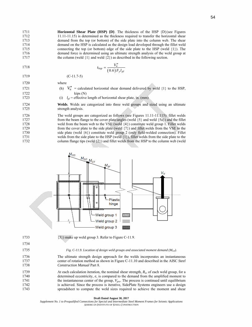
54
Draft Dated August 30, 2017 Supplement No. 1 to Prequalified Connections for Special and Intermediate Steel Moment Frames for Seismic Applications
AMERICAN INSTITUTE OF STEEL CONSTRUCTION
Horizontal Shear Plate (HSP) D. The thickness of the HSP D(see Figures 1711 11.11-11.15) is determined as the thickness required to transfer the horizontal shear 1712 demand from the top (or bottom) of the side plate into the column web. The shear 1713 demand on the HSP is calculated as the design load developed through the fillet weld 1714 connecting the top (or bottom) edge of the side plate to the HSP (weld 1). The 1715 demand force is determined using an ultimate strength analysis of the weld group at 1716 the column (weld 1 and weld 2) as described in the following section. 1717
0.6
uhsp
y pl
Vt
F l
1718
(C-11.7-5) 1719
where 1720
(h) uV = calculated horizontal shear demand delivered by weld 1 to the HSP, 1721 kips (N) 1722
(i) lpl = effective length of horizontal shear plate, in. (mm) 1723
Welds. Welds are categorized into three weld groups and sized using an ultimate 1724 strength analysis. 1725
The weld groups are categorized as follows (see Figures 11.11-11.115): fillet welds 1726 from the beam flange to the cover plate/angles (weld 5 and weld 5a) and the fillet 1727 weld from the beam web to the VSE (weld 4) constitute weld group 1. Fillet welds 1728 from the cover plate to the side plate (weld 7) and fillet welds from the VSE to the 1729 side plate (weld 6) constitute weld group 2 (only field-welded connection). Fillet 1730 welds from the side plate to the HSP (weld 1), fillet welds from the side plate to the 1731 column flange tips (weld 2) and fillet welds from the HSP to the column web (weld 1732
3) make up weld group 3. Refer to Figure C-11.9. 1733
1734
Fig. C-11.9. Location of design weld groups and associated moment demand (MG#). 1735
The ultimate strength design approach for the welds incorporates an instantaneous 1736 center of rotation method as shown in Figure C-11.10 and described in the AISC Steel 1737 Construction Manual Part 8. 1738
At each calculation iteration, the nominal shear strength, Rn, of each weld group, for a 1739 determined eccentricity, e, is compared to the demand from the amplified moment to 1740 the instantaneous center of the group, Vpre. The process is continued until equilibrium 1741 is achieved. Since the process is iterative, SidePlate Systems engineers use a design 1742 spreadsheet to compute the weld sizes required to achieve the moment and shear 1743
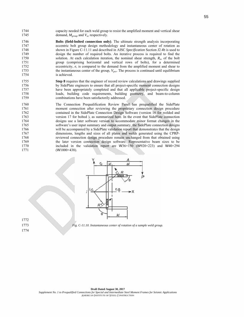
55
Draft Dated August 30, 2017 Supplement No. 1 to Prequalified Connections for Special and Intermediate Steel Moment Frames for Seismic Applications
AMERICAN INSTITUTE OF STEEL CONSTRUCTION
capacity needed for each weld group to resist the amplified moment and vertical shear 1744 demand, Mgroup and Vu, respectively. 1745
Bolts (field-bolted connection only). The ultimate strength analysis incorporating 1746 eccentric bolt group design methodology and instantaneous center of rotation as 1747 shown in Figure C-11.11 and described in AISC Specification Section J2.4b is used to 1748 design the number of required bolts. An iterative process is required to find the 1749 solution. At each calculation iteration, the nominal shear strength, Rn, of the bolt 1750 group (comprising horizontal and vertical rows of bolts), for a determined 1751 eccentricity, e, is compared to the demand from the amplified moment and shear to 1752 the instantaneous center of the group, Vpre. The process is continued until equilibrium 1753 is achieved. 1754
Step 8 requires that the engineer of record review calculations and drawings supplied 1755 by SidePlate engineers to ensure that all project-specific moment connection designs 1756 have been appropriately completed and that all applicable project-specific design 1757 loads, building code requirements, building geometry, and beam-to-column 1758 combinations have been satisfactorily addressed. 1759
The Connection Prequalification Review Panel has prequalified the SidePlate 1760 moment connection after reviewing the proprietary connection design procedure 1761 contained in the SidePlate Connection Design Software (version 16 for welded and 1762 version 17 for bolted ), as summarized here. In the event that SidePlate connection 1763 designs use a later software version to accommodate minor format changes in the 1764 software’s user input summary and output summary, the SidePlate connection designs 1765 will be accompanied by a SidePlate validation report that demonstrates that the design 1766 dimensions, lengths and sizes of all plates and welds generated using the CPRP-1767 reviewed connection design procedure remain unchanged from that obtained using 1768 the later version connection design software. Representative beam sizes to be 1769 included in the validation report are W36×150 (W920×223) and W40×294 1770 (W1000×438). 1771
1772
Fig. C-11.10. Instantaneous center of rotation of a sample weld group. 1773
1774

56
Draft Dated August 30, 2017 Supplement No. 1 to Prequalified Connections for Special and Intermediate Steel Moment Frames for Seismic Applications
AMERICAN INSTITUTE OF STEEL CONSTRUCTION
1775
Fig. C-11.11. Instantaneous center of rotation of a sample bolt group. 1776
1777

57
Draft Dated August 30, 2017 Supplement No. 1 to Prequalified Connections for Special and Intermediate Steel Moment Frames for Seismic Applications
AMERICAN INSTITUTE OF STEEL CONSTRUCTION
CHAPTER 14 1778
SlottedWebTM (SW) Moment Connection 1779
1780 14.1. GENERAL 1781
The SlottedWebTM (SW) connection is a proprietary welded steel beam to steel 1782 column connection developed through private funding by Seismic Structural 1783 Design Associates, Inc. (SSDA). In the SW moment connection, slots in the 1784 beam web are made parallel and adjacent to the beam flanges. These slots, 1785 which start at the end of the beam and are typically one third to one half the 1786 nominal beam depth in length, are terminated at a round stress relief hole. The 1787 beam web is welded to the column flange and also to the shear plate to give the 1788 web both shear and moment capacity. 1789
1790 Analytical studies by Yu (1959) and finite element analyses (FEA) by Abel and 1791 Popov (1968) have shown that the shear distribution at the support of cantilever 1792 beams differs drastically from that predicted by classical Bernoulli-Euler beam 1793 theory that lead to the popular design concept wherein “the flanges carry the 1794 moment and the web carries the shear.” It was shown that in the case of a rigid 1795 support (beam web and flanges welded to a rigid column flange), the entire 1796 shear is resisted by the flanges. For typical “Flange-Welded, Web-Bolted” 1797 connections such as the so-called pre-Northridge connection, however, about 1798 50% of the shear is resisted by the beam flanges. It is this 50% shear component 1799 in combination with the tension component that causes severe stress and strain 1800 gradients across and through the beam flanges of these connections. 1801
1802 By separating the beam flanges from the web in the region of the connection to 1803 the column, essentially all the beam shear is resisted by the beam web and, if the 1804 beam web is welded to the column, the web also resists a moment equal to the 1805 plastic moment capacity of the web, which is typically 30% of the beam plastic 1806 moment. Moreover, the elimination of the beam flange shear results in stress and 1807 strain gradients across and through the flanges to be nearly uniform. 1808
1809 Cyclic qualifying tests on the SW connection have been made using the single-1810 cantilever type and bare steel specimens; see test results in Table C-14.1. This 1811 pseudo-static test with the loading protocol developed by the FEMA/SAC 1812 program (FEMA, 2000) has been adopted in Section K2 of the AISC Seismic 1813 Provisions (AISC, 2016a). These tests, along with the FEA of the SW 1814 connection, show that the yielding region is concentrated in the separated 1815 portion of the beam flanges and in the beam web at the end of the shear plate. 1816 Peak strengths of the test specimens are usually achieved at an interstory drift 1817 angle of approximately 0.03 and 0.04 rad. Reduction in strength, if any, is 1818 gradual and due to the out-of-plane buckling of both the beam flanges and web. 1819 Buckling of the flanges and web occurs concurrently but independently, which 1820 eliminates the lateral torsional mode of buckling. Review of the SSDA test data 1821 indicates that the SW connection, when designed and constructed in accordance 1822 with the limits and procedures presented herein, have developed interstory drift 1823 angles of a least 0.04 radian under cyclic loading on a consistent basis. Ultimate 1824 failure typically occurs at drift angles of 0.05 to 0.07 rad by low cycle fatigue 1825 fracture of the flange near the end of the slot or partial fracture of the beam 1826 web/shear plate weldment to the column flange (Richard, et al., 2001; Partridge, 1827 et al., 2002). 1828
1829 14.2. SYSTEMS 1830

58
Draft Dated August 30, 2017 Supplement No. 1 to Prequalified Connections for Special and Intermediate Steel Moment Frames for Seismic Applications
AMERICAN INSTITUTE OF STEEL CONSTRUCTION
Review of the design rationale and the test results shown in Table C-1831 14.1indicates that the SW connection meets the prequalification requirements 1832 for special moment frames in Section K1 of the AISC Seismic Provisions. 1833
1834 14.3. PREQUALIFICATION LIMITS 1835 1836 1. Beam Limitations 1837
A wide range of beam sizes have been tested by SSDA with the SW connection. 1838 The smallest beam tested was a W24×94 (W61×140M). The largest was a 1839 W36×393 (W920×585M). The AISC Seismic Provisions permit limited 1840 increases in beam weight and depth compared to the maximum sections tested 1841 and there is no evidence that modest deviations from the maximum tested 1842 specimen would result in significantly different performance. 1843
1844 Both beam depth and beam span-to-depth ratios are significant in the inelastic 1845 behavior of beam-to-column connections. For the same induced curvature, deep 1846 beams will experience greater strains than shallower beams. Similarly, beams 1847 with shorter span-to-depth ratios will have a sharper moment gradient across the 1848 beam span, resulting in a reduced length of the beam participating in the plastic 1849 hinging and increased strains under inelastic rotational demands. The beam-to-1850 column assemblies that were tested by SSDA with the SW connection are given 1851 in Table C-14.1, which includes the test interstory drift ratios. 1852
1853
1854
Table C-14.1 SSDA Cyclic Tests and Summary of Results
Test No. Beam
Column Interstory Drift (%)
17 18
W33x141 W14x283
4.2 5.1
19 20
W27x94 W14x176
4.3 5.0
21 22
W36x300 W14x500
4.5 4.4
23 24
W24x94 W30x135
4.1 4.1
25 26
W36x170 W30x235
4.0 4.0
1a W36x256 W27x307
4.9
2a 3a
W36x393 W14x550 – (Gr. 65)
5.1 6.0
1855
1856 2. Column Limitations 1857
All of the SW tests have been performed with the beam flange welded to the 1858 column flange (i.e., strong-axis connections). The column sizes used in the tests 1859 ranged from W14 columns to W30 columns. 1860 1861 The behavior of SW connections with cruciform columns and box columns is 1862 expected to be similar to that of a rolled wide-flange column because the beam 1863 flanges frame into the column flange and the column panel zone is oriented 1864 parallel to that of the beam. For cruciform columns the web of the cut wide-1865 flange column is welded with a CJP groove weld to the continuous web one foot 1866 above and below the depth of the frame girder. Given these similarities and the 1867

59
Draft Dated August 30, 2017 Supplement No. 1 to Prequalified Connections for Special and Intermediate Steel Moment Frames for Seismic Applications
AMERICAN INSTITUTE OF STEEL CONSTRUCTION
lack of evidence suggesting behavior limit states different from those associated 1868 with rolled wide-flange shapes, cruciform and box column depths are permitted 1869 equal to those for rolled wide flange column depths. 1870
1871 14.4. BEAM-COLUMN RELATIONSHIP LIMITATIONS 1872 1873
The column panel zone strengths of the SW test specimens varied over a wide 1874 range. This includes specimens with strong panel zones wherein the yielding of 1875 the test specimen came primarily from the beam only, i.e. the panel zone 1876 participation in interstory drift was of the order of 12% to weak panel zones 1877 wherein the yielding of the test specimens comprised panel zone participation of 1878 the order of 50%. The behavior of columns with very weak panel zones can 1879 result in column flange “kinking” at the boundaries of the panel zone. However, 1880 for the SW connection, because the beam web slots provide flexibility to the 1881 beam flanges, the effects of this behavior are minimized. 1882
1883 1884
14.5. BEAM FLANGE-TO-COLUMN LIMITATIONS 1885 1886
CJP groove welds joining the beam flanges to the column flanges of the SW test 1887 connections were made using E70T-6-H16 electrodes with a minimum specified 1888 CVN toughness as specified in the AISC Seismic Provisions for demand critical 1889 welds. Further, the beam bottom flange backing was removed. The root weld 1890 pass was back-gouged out and replaced with new weld passes as required. A 1891 reinforcing fillet was then added to the bottom flange weld. At the top flange 1892 weld, the backing was fillet welded to the column flange. Weld tabs were 1893 removed at both the top and bottom flange welds. 1894
1895 14.6. BEAM WEB AND SHEAR PLATE CONNECTION LIMITATIONS 1896 1897
In all SW test connections the shear plate was welded directly to the column 1898 flange using either a CJP or a PJP weld over the full height of the shear plate. 1899 The beam web was welded to the face of the column flange, and the shear plate 1900 served as the backing for this weld. Further, an eccentrically loaded weld group 1901 consisting of fillet welds was used to join the shear plate to the beam web. These 1902 welds were made using E71T-8-H16 electrodes with the minimum CVN 1903 toughness specified in the AISC Seismic Provisions. Additionally, the shear 1904 plate was joined to the beam web with high strength pretensioned bolts. 1905
1906 14.7. FABRICATION OF THE BEAM WEB SLOTS 1907 1908
The beam web slots in the SW test specimens were flame cut along the “k-line” 1909 of the beam to a termination hole which was either drilled or thermally cut. The 1910 narrow slot width over the shear plate is designed to inhibit beam flange 1911 buckling near the face of the column (to protect the beam flange-to-column 1912 flange weld) and force the major beam flange buckling to occur over the wider 1913 part of the slot. 1914
1915 14.8. DESIGN PROCEDURE 1916 1917
The design rationale for the SW connection is based upon: 1918 1919
(a) The IBC (ICC, 2015) and the AISC Specification (AISC, 2016b) and the 1920 principles of plastic design 1921

60
Draft Dated August 30, 2017 Supplement No. 1 to Prequalified Connections for Special and Intermediate Steel Moment Frames for Seismic Applications
AMERICAN INSTITUTE OF STEEL CONSTRUCTION
(b) Results of cyclic qualification tests using beams ranging from W24×94 to 1922 W36×393 and columns ranging from W14×176 to W14×550 and 1923 W27×307 to W30×235 1924
(c) Inelastic finite element analyses to evaluate the stress and strain 1925 distributions and buckling modes 1926
1927 In Step 1 the beam slots are designed to: 1928
1929 (1) Force the beam shear at the connection to be carried predominately by the 1930 beam web. 1931
1932 (2) Provide a nearly uniform stress and strain distribution horizontally across 1933
and vertically through the beam flanges from the column face to the end of 1934 the beam web slot. 1935
1936 (3) Allow plastic beam flange and beam web buckling to occur independently 1937
in the region of the beam web slot. This eliminates the lateral-torsional 1938 mode of buckling found in beams where the beam web is not slotted. 1939
1940 (4) Ensure plastic beam flange buckling so that the full plastic moment 1941
capacity of the beam is developed: 1942 1943
0.60s
f y
l E
t F (C-14.8-1) 1944
1945 In Step 2(a) for SMF systems a maximum nominal height of the shear plate is 1946 used that can accommodate the slot and the weld across the top and bottom of 1947 the shear plate. The minimum thickness of the shear plate is based upon the 1948 moment increase in the connection from the plastic hinge at the end of the shear 1949 plate to the face of the column. Observations from the SW tests have shown that 1950 a shear plate equal to or greater than two-thirds the beam web thickness should 1951 be used to stabilize the beam web and shear plate from out-of plane bending to 1952 protect the web and plate welds at the column flange. To stabilize the beam web 1953 at the column flange use a minimum shear plate thickness of 2/3 of the beam 1954 web thickness but not less than 3/8 in. (10 mm). 1955
1956 In Step 3 AISC Specification tables may be used to determine the weld size of 1957 an eccentrically loaded weld group made from fillet welds for the shear plate 1958 based upon the shear plate moment and shear forces as shown in Figure C-14.1. 1959 1960

61
Draft Dated August 30, 2017 Supplement No. 1 to Prequalified Connections for Special and Intermediate Steel Moment Frames for Seismic Applications
AMERICAN INSTITUTE OF STEEL CONSTRUCTION
1961 Fig. C-14.1. Beam webshear plate force distribution. 1962
1963 In Step 4 the shear plate to column flange weld must exceed the fillet weld 1964 strength of the shear plate eccentrically loaded fillet weld group that resists the 1965 increase in the connection moment from the plastic hinge at the end of the shear 1966 plate to the column flange. 1967 1968 In Step 5(a) the bolts are designed for erection purposes and also to clamp the 1969 shear plate to the beam web. The effect of this clamping action minimizes the 1970 out of plane buckling of the plate and beam web near the column flange 1971 weldment. 1972
1973 In Step 7 a resistance factor of 1.0 is used and a Cv of 1.0 in accordance with 1974 Equation G2-2 based upon the 13 cyclic tests (as shown in Table C-14.1) and 1975 finite element analyses. 1976
1977 1978 1979 1980 1981
1982
1983
62
Draft Dated August 30, 2017 Supplement No. 1 to Prequalified Connections for Special and Intermediate Steel Moment Frames for Seismic Applications
AMERICAN INSTITUTE OF STEEL CONSTRUCTION
REFERENCES 1984 1985
1986 CHAPTER 11 1987 SIDEPLATE MOMENT CONNECTION 1988 1989
GSA (2008), “GSA Steel Frame Bomb Blast & Progressive Collapse Test Program 1990
(2004-2007) Summary Report,” January 10, prepared by MHP Structural Engineers 1991
for the U.S. General Services Administration (GSA), Office of the Chief Architect 1992
(OCA), Washington, DC. 1993
Hodgson, I.C., Tahmasebi, E. and Ricles, J.M. (2010a), “Cyclic Testing of Beam-to-1994 Column Assembly Connected with SidePlate FRAME Special Moment Frame 1995 Connections—Test Specimens 1A, 2A, and 2B,” ATLSS Report No. 10-12, 1996 December, Center for Advanced Technology for Large Structural Systems (ATLSS), 1997 Lehigh University, Bethlehem, PA. 1998
Hodgson, I.C., Tahmasebi, E. and Ricles, J.M. (2010b), “Cyclic Testing of Beam-to-1999 Column Assembly Connected with SidePlate Steel Moment Frame Connection—2000 Test Specimen 2C,” ATLSS Report No. 10-13, December, Center for Advanced 2001 Technology for Large Structural Systems (ATLSS), Lehigh University, Bethlehem, 2002 PA. 2003
Hodgson, I.C., Tahmasebi, E. and Ricles, J.M. (2010c), “Cyclic Testing of Beam-to-2004 Column Assembly Connected with SidePlate FRAME Special Moment Frame 2005 Connections—Test Specimens 1B and 3,” ATLSS Report No. 10-14, December, 2006 Center for Advanced Technology for Large Structural Systems (ATLSS), Lehigh 2007 University, Bethlehem, PA. 2008
ICC (2013a), Independent Pre-Qualification summarized in Evaluation Report by ICC 2009 Evaluation Service, Inc. (ICC-ES ESR-1275), “SidePlate Steel Frame Connection 2010 Technology,” issued May 1. 2011
ICC (2013b), Independent Pre-Qualification summarized in Research Report by 2012 Engineering Research Section, Department of Building and Safety, City of Los 2013 Angeles (COLA RR 25393), “GENERAL APPROVAL—SidePlate Steel Frame 2014 Connection Technology for Special Moment Frame (SMF) and Intermediate 2015 Moment Frame (IMF) Systems,” issued April 1. 2016
LACO (1997), Independent Evaluation and Acceptance Report by the Los Angeles 2017 County Technical Advisory Panel on Steel Moment Resisting Frame Connection 2018 Systems (LACO-TAP SMRF Bulletin No. 3, Chapter 2), “SidePlate Connection 2019 System,” dated March 4. 2020
Latham, C.T., Baumann, M.A. and Seible, F. (2004), “Laboratory Manual,” Structural 2021 Systems Research Project Report No. TR-97/09, May, Charles Lee Powell 2022 Structural Research Laboratories, University of California, San Diego, La Jolla, CA. 2023
Minh Huynh, Q. and Uang, C.M. (2012), “Cyclic Testing of SidePlate Steel Moment 2024 Frame for SMF Applications,” Structural Systems Research Project Report No. TR-2025 12-02, October, Charles Lee Powell Structural Research Laboratories, University of 2026 California, San Diego, La Jolla, CA. 2027

63
Draft Dated August 30, 2017 Supplement No. 1 to Prequalified Connections for Special and Intermediate Steel Moment Frames for Seismic Applications
AMERICAN INSTITUTE OF STEEL CONSTRUCTION
Richards, P. and Uang, C.M. (2003), “Cyclic Testing of SidePlate Steel Frame Moment 2028 Connections for the Sharp Memorial Hospital,” Structural Systems Research Project 2029 Report No. TR-2003/02, March, Charles Lee Powell Structural Research 2030 Laboratories, University of California, San Diego, La Jolla, CA. 2031
Richards, P. and Uang, C.M. (2003), “Cyclic Testing of SidePlate Steel Frame Moment 2032 Connections for Children’s Hospital Los Angeles,” Structural Systems Research 2033 Project Report No. TR-2003/03, May, Charles Lee Powell Structural Research 2034 Laboratories, University of California, San Diego, La Jolla, CA. 2035
Trautner, J.J. (1995), “Three-Dimensional Non-Linear Finite-Element Analysis of MNH-2036 SMRF™ Prototype Moment Connection,” System Reliability of Steel Connections 2037 Research Report No. 1, Department of Civil Engineering, University of Utah, Salt 2038 Lake City, UT. 2039
Uang, C.M. and Latham, C.T. (1995), “Cyclic Testing of Full-Scale MNH-SMR Moment 2040 Connections,” Structural Systems Research Project Report No. TR-95/01, March, 2041 Charles Lee Powell Structural Research Laboratories, University of California, San 2042 Diego, La Jolla, CA. 2043
Uang, C.M., Bondad, D. and Noel, S. (1996), “Cyclic Testing of the MNH-SMR Dual 2044 Strong Axes Moment Connection with Cruciform Column,” Structural Systems 2045 Research Project Report No. TR-96/04, May, Charles Lee Powell Structural 2046 Research Laboratories, University of California, San Diego, La Jolla, CA. 2047
2048 CHAPTER 14 2049 SLOTTEDWEB MOMENT CONNECTION 2050 2051 Abel, J.F. and Popov, E.P. (1968), "Static and Dynamic Finite Element Analysis of 2052
Sandwich Structures," Air Force Flight Dynamics Laboratory T.R. No. 68-150, pp. 2053 213245. 2054
2055 AISC (2016a), Seismic Provisions for Structural Steel Buildings, ANSI/AISC 341-16, 2056
American Institute of Steel Construction, Chicago, IL. 2057 2058 AISC (2016b), Specification for Structural Steel Buildings, ANSI/AISC 360-16, 2059
American Institute of Steel Construction, Chicago, IL. 2060 2061 FEMA (2000), “Steel Moment Frame Buildings: Design Criteria for New Buildings,” 2062
FEMA 350, SAC Joint Venture, Richmond, CA. 2063 2064 ICC (2015), International Building Code, International Code Council, Falls Church, VA. 2065 2066 Partridge, J.E., Allen, J., and Richard, R.M. (2002), "Failure Analysis of Structural Steel 2067
Connections in the Northridge and Loma Prieta Earthquakes," Proceedings of the 2068 Seventh U.S. National Conference on Earthquake Engineering, ST50/ST-11, July. 2069
2070 Richard, R.M., Partridge, J.E., and Allen, J. (2001), "Accumulated Seismic Connection 2071
Damage Based upon Full Scale Low Cycle Fatigue Connection Tests," Proceedings of 2072 the Structural Engineers Association of California 70th Annual Convention, 2073 September 27-29, pp. 4348. 2074
2075 Yu, Y.Y. (1959), "A New Theory of Elastic Sandwich Plates - One Dimensional Case," 2076
Journal of Applied Mechanics, Vol. 26, No. 3, pp. 415-423. 2077