superseeder 2400 operator’s manual
TRANSCRIPT

SuperSeeder 2400 Operator’s Manual

2
Introduction Thank you for purchasing this Stinger Equipment, Inc. product.
This manual will explain the safety, maintenance and operation of
your unit.
Safety All operators should read the product manual in its
entirety before operating. All operators must be properly
trained on the controls and their functions.
All safety equipment, shields and covers must remain in
place and free of any defects. Do not use this equipment
if any guards or safety decals are not in place.
Perform an inspection of the unit before each use. Ensure
all fasteners are secure, the tires are properly inflated and
engine oil level is correct.
Do not use this unit on a slope of more than 20 degrees.
Do not use if terrain exceeds skill or comfort level.
Refueling the unit: Use an OSHA approved fuel can
Do not fuel while the unit is running or hot
Absolutely no smoking while refueling
Refuel only outside and on level ground
Do not overfill the unit
Secure the fuel cap

3
This Symbol means: ATTENTION! TAKE NOTICE! Your attention is needed to ensure your safety and the safety of those around you. This symbol is
followed by a Signal word describing the level of hazard. Throughout this manual and on all equipment you will see these safety labels.
Signal word definitions:
DANGER indicates an imminently hazardous situation which, if not avoided, WILL result in death or serious injury.
WARNING indicates a potentially hazardous situation which, if not avoided, COULD result in death or serious injury.
CAUTION indicates a potentially hazardous situation which, if not avoided, MAY result in minor or moderate injury. It may also be used to alert against unsafe practices or property damage.

4
Maintenance
Turn the unit off as shown in Figure 1, and remove spark plug as shown in Figure 2 before performing any maintenance.
Hydrostatic transmissions The hydrostatic transmissions features a maintenance-free
design.
Belt Inspect the belts every 50 hours, or annually, for signs of
wear. Blade Belt Replacement Procedure:
1. Put blade engagement level in off position (up). 2. Remove belt cover. 3. Take note of the belt orientation and pathway in figure
3 before removing and discard old belt. 4. Replace with new belt. Reinstall belt cover. Belt will
auto tension.

5
Figure 3
Figure 1
Figure 2

6
Engine Run unleaded gasoline with an octane rating of 86 or higher
and 10% or less ethanol. Check engine oil level on level ground daily Drain Honda engine’s oil by removing oil plug in figure 5. Change the oil within the first month or 10 hours, do not
overfill unit. Regular oil changes are required every 6 months or 50 hours
or sooner depending on conditions. 10w30 is recommended Clean/replace the air filter every 3 months or 25 hours. See supplemental Engine manufacturer booklet for
additional maintenance procedures and requirements
Grease Points
Grease the 2 bearings on the cutting shaft every 50 hours as shown in Figure 4.
Grease single bearing on the engine shaft every 50 hours as shown in Figure 5 .
Operation
Starting and Stopping the Engine
1. Turn engine switch to “On” position

7
Figure 4
Figure 5

8
4. Give a quick pull to the recoil. 5. Allow the unit to warm up and slide the choke off and set throttle to the desired rpm. 6. Turn engine switch to “Off” position to stop the engine.
Setting Blade Depth
1. With the blades off, squeeze depth control lever up as shown in figure 6.
2. Rotate the handle forward until the blades touch the ground. Push forward one additional notch to set proper depth for most applications and release lever.
3. Raise the blades to transport the unit across hard surfaces.
Setting Seed Flow
1. Loosen wing nut as shown in figure 7. 2. Rotate dial from 1-11 to increase seed flow. The
higher the number the more seed that will be delivered.
3. Tighten wing nut Note: Different seed types will have different seed flow rates.

9
Figure 6
Figure 7
10
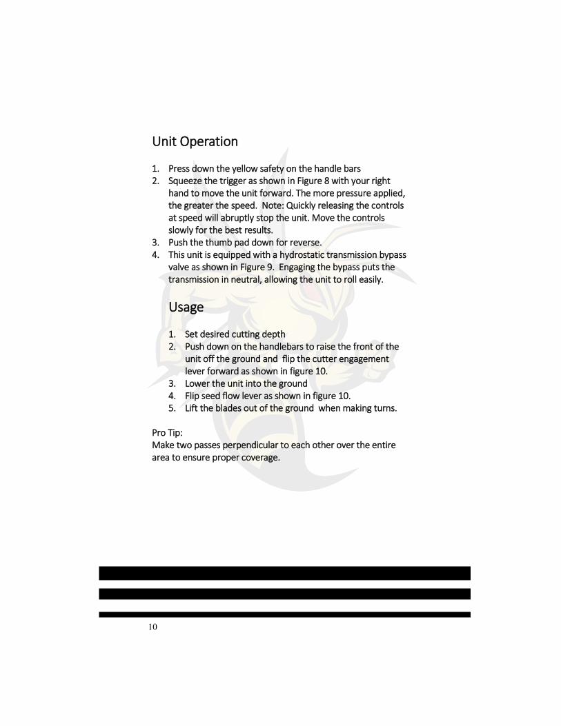
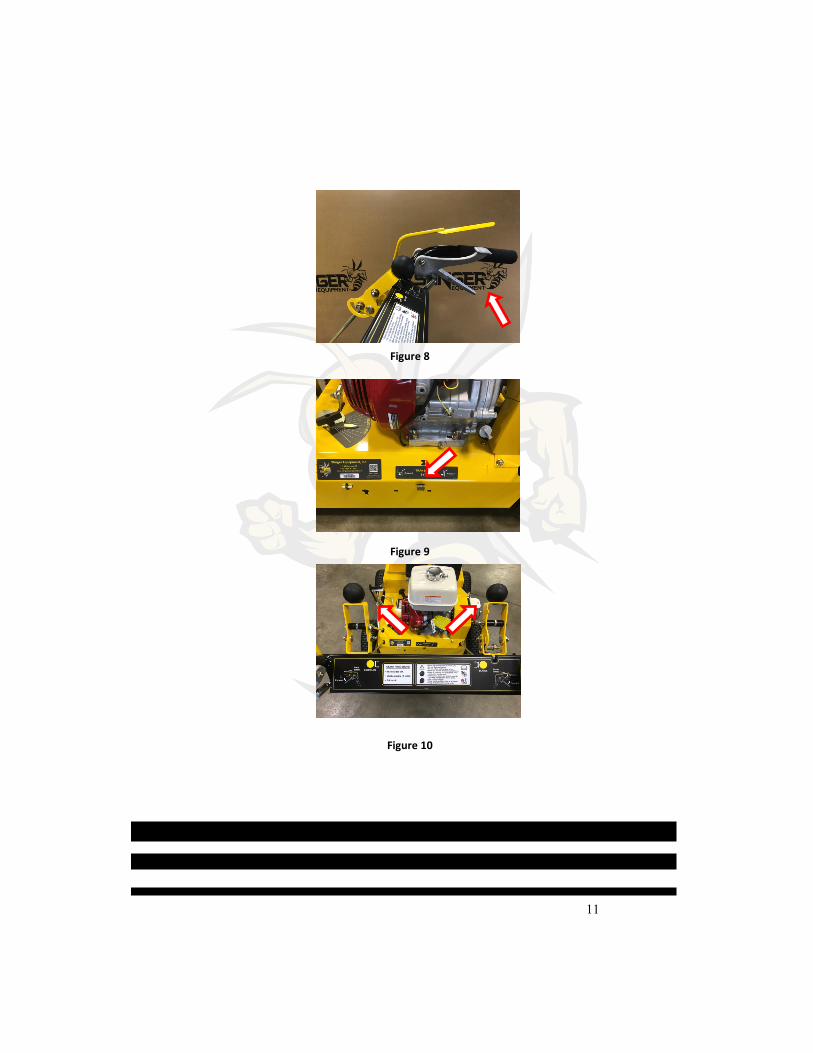
Unit Operation 1. Press down the yellow safety on the handle bars 2. Squeeze the trigger as shown in Figure 8 with your right
hand to move the unit forward. The more pressure applied, the greater the speed. Note: Quickly releasing the controls at speed will abruptly stop the unit. Move the controls slowly for the best results.
3. Push the thumb pad down for reverse. 4. This unit is equipped with a hydrostatic transmission bypass
valve as shown in Figure 9. Engaging the bypass puts the transmission in neutral, allowing the unit to roll easily.
Usage 1. Set desired cutting depth 2. Push down on the handlebars to raise the front of the
unit off the ground and flip the cutter engagement lever forward as shown in figure 10.
3. Lower the unit into the ground 4. Flip seed flow lever as shown in figure 10. 5. Lift the blades out of the ground when making turns.
Pro Tip: Make two passes perpendicular to each other over the entire area to ensure proper coverage.
11
Figure 8
Figure 9
Figure 10

www.StingerEquipment.com 2140 Spencer Court LaGrange, KY 40031
(502) 536-0716