superrail mounting kit #3349 - pullrite
TRANSCRIPT
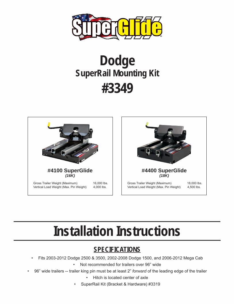
SPECIFICATIONS• Fits2003-2012Dodge2500&3500,2002-2008Dodge1500,and2006-2012MegaCab
• Notrecommendedfortrailersover96”wide• 96”widetrailers--trailerkingpinmustbeatleast2”forwardoftheleadingedgeofthetrailer
• Hitchislocatedcenterofaxle• SuperRailKit(Bracket&Hardware)#3319
Installation Instructions
DodgeSuperRail Mounting Kit
#3349
#4100 SuperGlide(16K)
GrossTrailerWeight(Maximum) 16,000lbs.VerticalLoadWeight(Max.PinWeight)4,000lbs.
#4400 SuperGlide(18K)
GrossTrailerWeight(Maximum) 18,000lbs.VerticalLoadWeight(Max.PinWeight)4,500lbs.
2 #3349 SG Installation Instructions (rev. 1-3-11)
IMPORTANTDO NOT OPERATE HITCH UNTIL YOU READ THIS SECTION!
1. TheSuperGlidehitchwasdesignedtoallowtheTurntableCamArmAssemblyto“glide”alongtwometaltubes,calledtheWayTubes.Sinceit’sreleasein1998,wehavemadeseveraladvancementsinthedesign,strength,anddurabilityofthesecomponents.TheLubricationsectionofyourOwnersManualspansseveralproductreleasesanddesignchanges.ItisimperativethatyoureadeachsectionanddeterminewhichSuperGlidehitchyoupurchased,andhowtocareforit.TherehavebeenthreemajorlubricationchangestotheSuperGlidehitch:
• PriortoApril2008,WayTubeswereassembledwitheitheraconventional,qualitygradegreaseornoneatall• InApril2008,westartedcoatingtheWayTubeswithagraphite-basedspraylubricantcalledSlipPlate™• November2009bringsanewinnovationfromPullRiteTowingSystemswiththeuseofplastics.TheTurntableCamArm
AssemblyisnowequippedwithPlasticWearPlates;seeOwnersManualfordetails(notavailablefor#3600models)
Dependingonwhenyourhitchwasmanufactured,theWayTubesofyournewSuperGlidehitchwillmeetoneoftheabovecriteria.Eachapplicationlistedrequiressomelevelofmaintenance,soitisimportantthatyoureadthefollowinginstructionscarefullyforthecorrectlubricationinstructions.
Failure to properly lubricate the Way Tubes, as directed in this section, will eventually cause galling between the metals of the Way Tubes and Cam Arm Assembly, which will result in hitch failure.
Destruction of various hitch parts is also likely, as well as truck and/or trailer damage, and will not be covered under the Manufacturer’s Warranty.
2. THE TRAILER’S KING PIN BOX MUST BE EQUIPPED WITH A CAPTURE PLATE (UNIVERSAL OR QUICK CONNECT) TO ALLOW THE HITCH TO FUNCTION (MUST BE PURCHASED SEPARATELY). NOTE: IF YOU HAVE PURCHASED A QUICK CONNECT CAPTURE PLATE AND DID NOT RECEIVE INSTRUCTIONS, THEY ARE AVAILABLE ONLINE, OR YOU CAN CONTACT PULLRITE CUSTOMER SERVICE AT (800) 443-2307.
3. Failuretomodifythelengthofthebrakeawaycablethatactivatestheemergencybrakingofyourtrailer,maycausethecabletocatchonprotrudingpartsofthehitch.Resultingdamagewillnotbecoveredbythemanufacturerswarranty.
4. Thereshouldbeaminimumof6”betweenthetruckbedrailsandtheundersideofthetrailerforsidetiltclearance.Itisthecustomersresponsibilitytoadjustthetrailerkingpinboxfortheappropriateamountofclearance.
NOTE:Sometruckmodelsarebeingmanufacturedwithhigherbedsides,makingitnecessarytoadjusttheheightofyourtrailer’skingpinbox.Ifyoudon’thaveenoughheightadjustmentavailable,PullRiteproducesa3”LiftKitthatattachestotherailsofyour#3100(askforpart#3108)or#4100,#3300and#4400(askforpart#4408)SuperGlidemodels.
5. Sometruckbedshavecontouredbedsides,makingtheinsidebedmeasurementnarrower.Makecertainthetrailer’skingpinboxdoesnotcontacttheinsideedgeofthebed.
6. TruckswithbedlinersmayneedatallMountingPost.See“NOTE”under“DrillingtheBed”forfurtherdetails.
7. Itistheinstallersandcustomersresponsibilitytoensurethereisproperclearancebetweenthetruckandtrailer.Thereshouldbeaminimumof2”ofclearanceasthetrailerpassesthecab.CallPullRitetechnicalsupportwithtrailerwidth,makeandyearoftruckanddistancethekingpinisfromleadingedgeofthetrailer(See“Caution”section,intheSuperGlideOwnersManual,formeasuringprocedure)at(800)443-2307.
8. Readtheseinstructionscompletelyandfollowthemaccurately.Shouldyouhaveanyquestions,pleasecallCustomerServiceat(800)443-2307priortoinstallationforassistance.If you did not recieve your Owners Manual, visit us online at www.pullrite.com or call the number above.
9. TheSuperGlidewasdesignedforshortbedpickuptrucks.Thehitchmayfunctioninalongerbedtruck,butnomountingbracketsexisttomakethetransfer.Some#4100and#4400mountingkitsmaytransferwithmodification.

#3349 SG Installation Instructions (rev. 1-3-11) 3
TABLE OF CONTENTS
MOuNTINGHARDWAREPARTSIDENTIFICATION......................................................4
PARTSLIST.....................................................................................................................5
TRuCKPREPARATION...................................................................................................6
MARKINGTHEBEDFORDRILLING..............................................................................6
LAyOuTMETHOD...................................................................................................6
TEMPLATEMETHOD..............................................................................................7
INSTALLATION................................................................................................................8
PART1:BRACKETPLACEMENT&BEDHOLELOCATIONS...............................8
PART2:DRILLINGTHEBED&BRACKETINSTALLATION................................10
REARMOuNTINGBRACKETINSTALLATION..............................................10
FRONTMOuNTINGBRACKETINSTALLATION............................................10
PART3:HITCHALIGNMENT................................................................................11
PART4:FINALINSTALLATIONPROCEDuRES.................................................. 11
4 #3349 SG Installation Instructions (rev. 1-3-11)
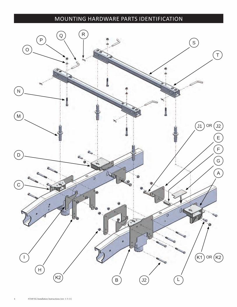
MOUNTINg HARDwARE PARTS IDENTIFICATION
A
g
f
e
B
h
I
C
D
Lj2K2
j1
M
n
Os
T
Pq R
K1
j2OR
K2OR
#3349 SG Installation Instructions (rev. 1-3-11) 5
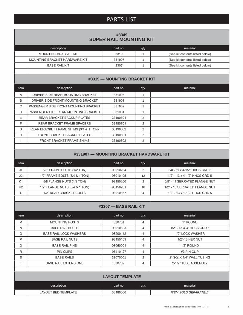
PARTS LIST
#3349SUPER RAIL MOUNTING KIT
description partno. qty material
MOuNTINGBRACKETKIT 3319 1 (Seekitcontentslistedbelow)
MOuNTINGBRACKETHARDWAREKIT 331907 1 (Seekitcontentslistedbelow)
BASERAILKIT 3307 1 (Seekitcontentslistedbelow)
#3319 — MOUNTING BRACKET KIT
item description partno. qty. material
A DRIVERSIDEREARMOuNTINGBRACKET 331903 1
B DRIVERSIDEFRONTMOuNTINGBRACKET 331901 1
C PASSENGERSIDEFRONTMOuNTINGBRACKET 331902 1
D PASSENGERSIDEREARMOuNTINGBRACKET 331904 1
e REARBRACKETBACKuPPLATES 33190601 2
f REARBRACKETFRAMESPACERS 33180701 2
g REARBRACKETFRAMESHIMS(3/4&1TON) 33190602 2
h FRONTBRACKETBACKuPPLATES 33190501 2
I FRONTBRACKETFRAMESHIMS 33190502 2
#331907 — MOUNTING BRACKET HARDWARE KIT
item description partno. qty. material
j1 5/8”FRAMEBOLTS(1/2TON) 98010234 2 5/8-11x4-1/2”HHCSGRD5
j2 1/2”FRAMEBOLTS(3/4&1TON) 98010195 12 1/2”-13x4-1/2”HHCSGRD5
K1 5/8FLANGENuTS(1/2TON) 98150200 2 5/8”-11SERRATEDFLANGENuT
K2 1/2”FLANGENuTS(3/4&1TON) 98150201 16 1/2”-13SERRATEDFLANGENuT
L 1/2”REARBRACKETBOLTS 98010167 4 1/2”-13x1-1/2”HHCSGRD5
#3307 — BASE RAIL KIT
item description partno. qty. material
M MOuNTINGPOSTS 330701 4 1”ROuND
n BASERAILBOLTS 98010183 4 1/2”-13X3”HHCSGRD5
O BASERAILLOCKWASHERS 98200142 4 1/2”LOCKWASHER
P BASERAILNuTS 98150153 4 1/2”-13HEXNuT
q BASERAILPINS 08060001 4 1/2”ROuND
R PINCLIPS 98410127 4 #3PINCLIP
s BASERAILS 33070001 2 2”SQ.X1/4”WALLTuBING
T BASERAILEXTENSIONS 330702 4 2-1/2”TuBEASSEMBLy
LAYOUT TEMPLATE
description partno. qty. material
LAyOuTBEDTEMPLATE 33180000 IteM sOld separately

6 #3349 SG Installation Instructions (rev. 1-3-11)
TRUCk PREPARATION
TRUCK BED DIMENSION TABLELAYOUT METHOD TEMPLATE METHOD
“A” “B” “C” “D” “X” Template part#
22” 21-3/16” 39-1/8” 41-1/2” 21” 33180000
If you purchased an installation template, please proceed “Template Method.” Templates are sold separately.
1. Referencing “Truck Bed Dimension Table” below, measure and mark from the back of the bed forward, the values for “A” and “B”. Do this at any point on both sides of the bed.
2. Draw a line across the bed from mark to mark.
3. Find the center line of the bed.
4. Draw a line down the middle of the bed from front-to-rear.
5. Center the measurement of “C” across the center line at the front-most line you made in step 2 and mark the measurement on each side (parallel to the center line).
6. Center the measurement of “D” for the rear most line made in Step 2, and again mark the measurement on each side (parallel to the center line). This will locate the 4 drill holes.
MARkINg THE BED FOR DRILLINg
LAYOUT METHOD
CL
C
B
AD
1. Check part quantities using the Parts List.
2. Block vehicle wheels. Some vehicles may require you to raise the rear of the truck in order to make it easier to drill for installing the mounting brackets on the truck frame.
3. You may wish to remove the wheels to give yourself greater working room.
4. Carefully remove the plastic inner wheel well guards on both sides of the vehicle.
5. Remove the spare tire.
6. If you have purchased a template, proceed to the “Template Method” below; otherwise, begin with the “Layout Method.”

#3349 SG Installation Instructions (rev. 1-3-11) 7
1. Lay the template in the truck bed, centering it from side-to-side, and parallel to the end of the truck bed using the dimension “X” listed in “Truck Bed Dimension Table.”
2. Mark the 4 holes, while making sure the template does not move.
NOTE: The TEMPLATE should be orientated as shown in the drawing below. Notice that the spacing of the forward and rearward facing holes may be different, and can be used to determine the correct orientation of the template. Item “C” in the table below shows the forward facing dimension, and Item “D” , the rearward facing dimension. Note also, the information etched into the template — the direction of the cab, the template number and the revision date.
INSTALLATION TIP: The template has a tendency to move when placed on the slick paint of new truck beds, and it may be helpful to place a small piece of NON-SKID matting, such as “SCOOT-GARD” ™ or simply use duct tape on each corner to help keep the template from moving.
TEMPLATE METHOD
ENDOFBED
Centerlineoftruckbed
21”Tothefirstedgeoftemplate
(X)
Centerlineofaxle
8 #3349 SG Installation Instructions (rev. 1-3-11)
INSTALLATION
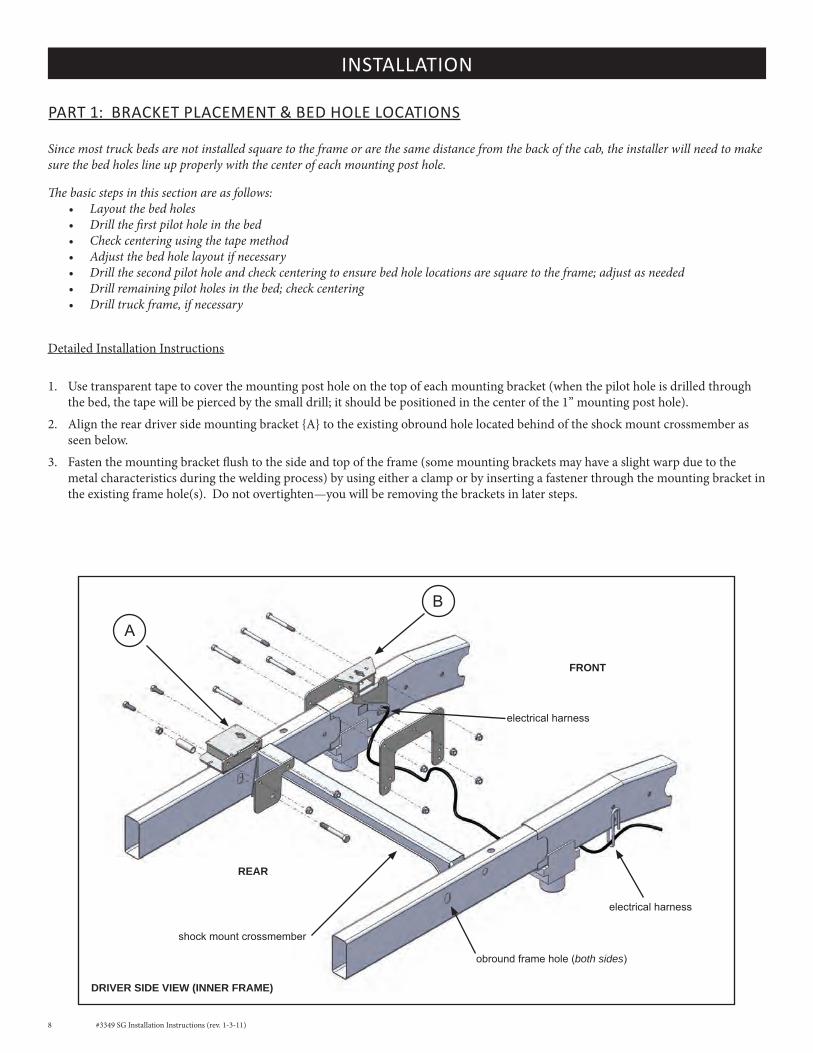
Since most truck beds are not installed square to the frame or are the same distance from the back of the cab, the installer will need to make sure the bed holes line up properly with the center of each mounting post hole.
The basic steps in this section are as follows:• Layout the bed holes• Drill the first pilot hole in the bed• Check centering using the tape method• Adjust the bed hole layout if necessary• Drill the second pilot hole and check centering to ensure bed hole locations are square to the frame; adjust as needed• Drill remaining pilot holes in the bed; check centering• Drill truck frame, if necessary
Detailed Installation Instructions
1. Use transparent tape to cover the mounting post hole on the top of each mounting bracket (when the pilot hole is drilled through the bed, the tape will be pierced by the small drill; it should be positioned in the center of the 1” mounting post hole).
2. Align the rear driver side mounting bracket {A} to the existing obround hole located behind of the shock mount crossmember as seen below.
3. Fasten the mounting bracket flush to the side and top of the frame (some mounting brackets may have a slight warp due to the metal characteristics during the welding process) by using either a clamp or by inserting a fastener through the mounting bracket in the existing frame hole(s). Do not overtighten—you will be removing the brackets in later steps.
PART 1: BRACkET PLACEMENT & BED HOLE LOCATIONS
electricalharness
DRIVER SIDE VIEW (INNER FRAME)
REAR
FRONT
electricalharness
A
B
shockmountcrossmember
obroundframehole(both sides)

#3349 SG Installation Instructions (rev. 1-3-11) 9
INSTALLATION
4. Drill the first 1/16” pilot hole through the truck bed over the rear hole on the driver side where you made the mark during the “Marking Bed for Drilling.” The bit should come down through the 1” mounting post hole, piercing the transparent tape, aiding the centering of the bracket front-to-rear and side-to-side.
5. If the pilot hole is off center to the 1” mounting post hole, remember to adjust all the pilot hole locations accordingly.
NOTE: Some truck beds are not installed square on their frame by the manufacturer. To ensure your pilot holes are aligned properly, it is important that you use the measurements provided only as a starting point and make adjustments as needed. Once you have the rear driver side pilot hole centered, you will use this hole as a point of reference for all remaining pilot hole adjustments. If you are using the Template Method, simply use the properly drilled hole as a pivot point to square the remaining holes to the frame. If you are using the Layout Method, you may accomplish the same thing by using a framing square and straight edge.
6. Repeat Steps 2-5 for the rear passenger side mounting bracket {D}, checking carefully for proper centering. Note: 2010 2500 & 3500 models have a heat shield on the rear passenger side. Simply drill through the shield and continue as directed.
7. The front mounting brackets {B} and {C}are positioned above the vehicle’s jounce bumper on the frame as illustrated below. Repeat Steps 3-5 for both front mounting brackets, making sure both brackets sit flush on top of the frame.
NOTE: Final bracket placement is dependent on the fixed position of the rear brackets. The front mounting brackets can be moved forward and back to achieve the “B” measurement indicated on “Truck Bed Dimension Table.”
WARNING: Before proceeding to “Part 2, ‘Drilling the Bed…,’” you must verify that each pilot hole is centered over the 1” mounting post hole on each bracket before the 1-3/4” mounting post holes are drilled through the bed.
DRIVER SIDE VIEW
REAR
FRONT
C
D
B
A
{G}rearbracketframeshim (3/4 and 1 ton only)

10 #3349 SG Installation Instructions (rev. 1-3-11)
PART 2: DRILLINg THE BED & BRACkET INSTALLATION
1. After removing the mounting brackets, use a 1-3/4” hole saw centered over the 1/16” pilot hole and cut the bed for the mounting posts.
2. De-bur inside the holes and use a paint stick to touch up the edges.
REAR MOUNTINg BRACkET INSTALLATION
1. Install the rear mounting brackets to the frame by first inserting the rear bracket frame spacers {F} into the truck frame.
NOTE: There is a flat side to this spacer. This prevents the spacer from turning in the obround frame hole during installation. Insert the flat side of the spacer parallel to the side of the obround hole in the truck frame as seen in the illustration below.
2. Place the rear mounting bracket flush to the side of the frame and insert the frame bolt (5/8” for 1/2 ton Dodge or 1/2” for 3/4 and 1 ton Dodge applications. Refer to the Parts List) through the frame and rear bracket frame spacer, noting the orientation of the bolt as seen in the illustration.
• 3/4 and 1 ton Dodge applications require the use of the rear bracket frame shim {G}. Sandwich the shim between the bottom of the bracket and the top of the truck frame and loosely tighten into place (see additional illustrations on page 9).
• 1/2 ton applications simply sit flush on the top and side of the truck frame. Loosely tighten into place.
3. Install the remaining rear bracket bolts {L} and loosely tighten.
FRONT MOUNTINg BRACkET INSTALLATION
1. Reinstall the front mounting brackets, frame shims, and backup plates as indicated, using the hardware provided (see illustration). Loosely tighten the assembly to the frame as you may need to adjust the assembly in later steps.
NOTE: The front mounting brackets use a frame shim {I} (1/2 ton only) on the inside of the truck frame. Install each frame shim according to the orientation seen in the illustration to the right.
A L
f
gj1 j2OR
K1 K2OR
h I B
j2
K2
#3349 SG Installation Instructions (rev. 1-3-11) 11
PART 2: DRILLINg THE BED & BRACkET INSTALLATION (CONT.)
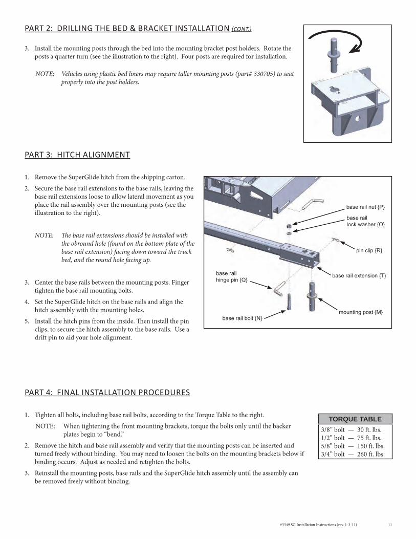
3. Install the mounting posts through the bed into the mounting bracket post holders. Rotate the posts a quarter turn (see the illustration to the right). Four posts are required for installation.
NOTE: Vehicles using plastic bed liners may require taller mounting posts (part# 330705) to seat properly into the post holders.
PART 3: HITCH ALIgNMENT
1. Remove the SuperGlide hitch from the shipping carton.
2. Secure the base rail extensions to the base rails, leaving the base rail extensions loose to allow lateral movement as you place the rail assembly over the mounting posts (see the illustration to the right).
NOTE: The base rail extensions should be installed with the obround hole (found on the bottom plate of the base rail extension) facing down toward the truck bed, and the round hole facing up.
3. Center the base rails between the mounting posts. Finger tighten the base rail mounting bolts.
4. Set the SuperGlide hitch on the base rails and align the hitch assembly with the mounting holes.
5. Install the hitch pins from the inside. Then install the pin clips, to secure the hitch assembly to the base rails. Use a drift pin to aid your hole alignment.
PART 4: FINAL INSTALLATION PROCEDURES
1. Tighten all bolts, including base rail bolts, according to the Torque Table to the right.
NOTE: When tightening the front mounting brackets, torque the bolts only until the backer plates begin to “bend.”
2. Remove the hitch and base rail assembly and verify that the mounting posts can be inserted and turned freely without binding. You may need to loosen the bolts on the mounting brackets below if binding occurs. Adjust as needed and retighten the bolts.
3. Reinstall the mounting posts, base rails and the SuperGlide hitch assembly until the assembly can be removed freely without binding.
TORQUE TABLE3/8” bolt — 30 ft. lbs.1/2” bolt — 75 ft. lbs.5/8” bolt — 150 ft. lbs.3/4” bolt — 260 ft. lbs.
baserailhingepin{Q}
pinclip{R}
mountingpost{M}baserailbolt{N}
baserailnut{P}
baseraillockwasher{O}
baserailextension{T}

MaNUFaCtUred By:PuLLIAMENTERPRISES,INC.13790EastJeffersonBlvd.Mishawaka,IN46545
(574)259-1520•(800)[email protected]•www.pullrite.com