supercritical organic rankine cycle yields useful power ... · supercritical organic rankine cycle...
TRANSCRIPT
INEC, April 2016, Bristol, UK
© 2016. IMarEST
Supercritical Organic Rankine Cycle
yields useful power and emissions
benefits
John Buckingham, CEng FIMechE
BMT Defence Services Limited, UK
Sean McCracken,
Granite Power Limited, Australia
SYNOPSIS
The energy contained within the exhaust gases of ship’s engines offers a good potential source for useful energy using waste
heat recovery. Organic Rankine Cycles (ORC) are now a proven technology, but remain little used on ships (beyond some
limited trials) as it appears ship owners have not yet been convinced on their benefits. For naval ships a reduced infra-red
emissions signature is one of the potential benefits.
A recently developed supercritical version of the ORC called ScORC GRANEX®, has many desirable features for marine
applications. Compared to a standard Rankine cycle it requires less heat exchanger surface area and has greater
thermodynamic efficiency delivering more useful power. This leads to a more compact system that can be more easily
retrofitted with a reduced payback term.
This paper presents the performance features of the GRANEX® technology and examines the conceptual installation on
large naval vessels such as the Queen Elizabeth class of aircraft carrier. Based on best estimates of the engine exhaust data at
specific loadings, the recovered electrical energy is identified to determine the fuel saved, the emissions reduced and the
increased range of a transit. The estimated size and weight of equipment is identified to allow installation costs to be
estimated. The calculated fuel savings on typical ship operations may be over 10% and the likely return of investment and
payback period are estimated.
BACKGROUND/CONTEXT
Organic Rankine cycle (ORC) sets are used on land-based applications such as waste gas heat rejection from gas-fuelled
generator sets at landfill sites and as part of Combined Heat and Power (CHP) systems. To date there has been a limited
uptake onboard ship due to the lack of marketed products which are certified to meet classification society requirements.
There is also a lack of a defined commercial approach to achieving an installation which has a robust commercial
footing. This study seeks to show that ORC have a useful role to play in achieving useful fuel efficiency benefits once
they have overcome Class requirements.
There have been many recent articles and technical papers on ORC and in recent years Enertime and OpCon Marine
(Ref 1) have claimed to have successfully trialled an ORC system on a marine engine. A few key documents which
have influenced our work are reviewed below.
Auld (Ref 2) describes the use of sub-critical ORC with three different waste heat sources one of which is the waste heat
from an engine. The analysis uses a direct exhaust heat transfer from exhaust gas to the refrigerant. The paper provides
an insight into the optimisation of an ORC cycle, something which this model is not intended to do due to its general
applicability for a range of engines. Auld makes reference to the Super Truck programme sponsored by the US DOE
(Ref 3) which sought to reduce fuel consumption by 10%. The program uses the Cummins ORC system but there is
INEC, April 2016, Bristol, UK
© 2016. IMarEST
limited information available in public on its use. Katsanos (2010) has also studied the use of ORC on trucks and using
some assumptions and the use of R245fa as the working fluid (wf), he achieves an overall fuel reduction of 8 to 10%
when used with Exhaust Gas Recirculation (EGR).
Moghtaderi (Ref 4) made a case for the adoption of a Supercritical Organic Rankine cycle (SORC) so that the wf
temperature is closer to that of the heat source and thus there is better use of the available heat. Due to the typical
proximity of the lines of constant pressure in the Turbine Inlet Pressure (TIP) region the turbine exit stream may have a
higher energy content than a conventional ORC. For this reason the SORC is employed with a recuperator to provide a
better yield for the fluid heater heat and to reduce the heat lost through the condenser. The recuperator improves the net
yield per unit enthalpy change.
Suarez de la Fuente (2013, Ref 5) considers the application of ORC to two-stroke engines and assesses the potential
range of wf.
This paper presents the application of SORC technology from Granite Power Limited (GPL) of Sydney, Australia to the
Queen Elizabeth Class (QEC) aircraft carrier. GPL supply SORC systems which generate useful power from a wide
range of heat sources. BMT have worked with GPL to model the performance and behaviour of their equipment
onboard the QEC.
OBJECTIVE
These studies seek to identify the fuel consumption savings achieved through the application of SORC on the QEC
design. As the QEC is an all-electric ship with both gas turbine (GT) and Diesel gensets, the SORC can make a useful
contribution to the supply to the Ships Electrical Load (SEL) whilst also raising the total effective power generating
capacity.
A steady-state SORC model was used to analyse the ship’s power and propulsion system to a level which is robust and
accurate enough to allow the benefits and operating issues of an SORC system to be identified with confidence.
The SORC is driven by the heat recovery from the exhaust gas of the GT engine and the diesel engines (DE). The
model is to allow the electrical output power to be determined which supplies the SEL and which supplements the power
supply from the gensets themselves.
DESCRIPTION
A conventional Rankine cycle comprises a boiler which heats water into steam. The steam drives a turbine which then
drives the load. The vapour exiting the turbine is cooled to water by a water-cooled condenser. The water collects in a
well from whence it is pumped to the boiler by the feed pump and the cycle starts over again.
In an SORC system the water is replaced with a refrigerant wf. This allows the fluid to evaporate at temperatures below
100°C and thus can be used for the recovery of useful work from so-called "low-grade" sources of heat and often results
in a more compact solution. At higher grade sources temperatures, like that of a GT exhaust, SORC seldom achieves an
efficiency comparable to the steam Rankine cycle, however, an SORC fluid is of much higher molecular weight than
steam, and compounded with a lower expansion ratio in the turbine, a SORC turbine expander is considerably more
compact than a steam turbine expander. For most marine GT installations, the complication and size of a steam cycle is
very unattractive and this is why SORC, despite a lower efficiency than steam, becomes a formidable solution.
SPECIFICATION
SCOPE
The model developed to represent an SORC system is based on a pragmatic design which is robust enough to identify
the benefits across the load range with a wide range of heat and temperatures sources using a standard sea water
temperature indicative of North European waters.
INEC, April 2016, Bristol, UK
© 2016. IMarEST
HEAT SOURCE
In this case study, the exhaust gas heats the R134a refrigerant directly in a heat collector placed in the engines’ exhaust
gas streams. The assumed funnel temperature of 120°C or above is high enough for operations with fuel of 0.1%
sulphur to avoid the risk of sulphuric acid condensing and causing corrosion. In order to vary the heat load to the fluid
heater, the wf flow to the fluid heater is varied at a constant temperature, this ensures that the SORC system operates at
(or near) its thermodynamic design point.
WORKING FLUID
The wf of a SORC system is to be affordable with an acceptable Global Warming Potential (GWP). The GPL supplied
system is designed as a gas-tight system with minimal leakage. The wf is to ideally have low toxicity and low
flammability.
The refrigerant chosen as the wf for these studies is R134a: it is non-flammable which allows it to be used in ships'
machinery spaces and is a commonly available refrigerant which is often found in ship's provision plants. R134a
represents the right balance to a number of selection issues. Although it has a high GWP, its high availability and proven
use makes it a good candidate for the basis of these studies. Alternative wf such as CO2 require high pressures and
complex pump-compressor arrangements.
CONDENSING FLUID
For this study the heat sink is sea water which is the standard cooling medium onboard ship. The temperature of the sea
water (Tsw) to the condenser is 10.0°C based on the annual average sea water temperature around Northern European
waters (Defra: Ref 6).
PHYSICAL MODELS
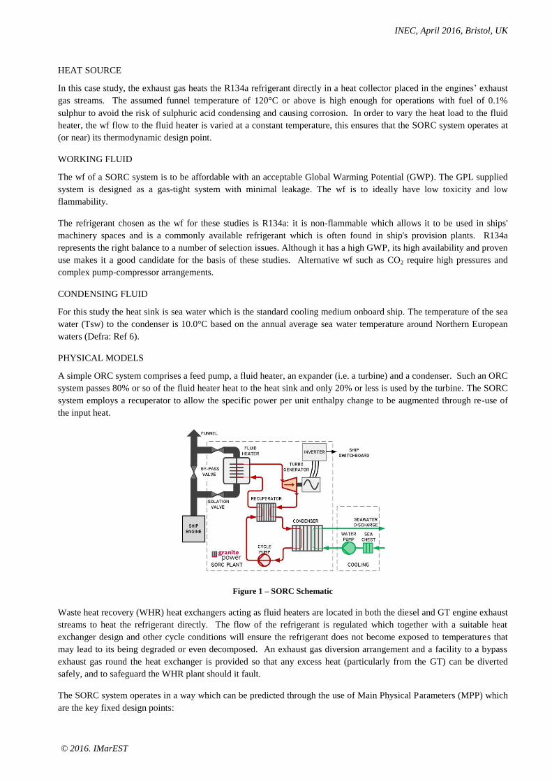
A simple ORC system comprises a feed pump, a fluid heater, an expander (i.e. a turbine) and a condenser. Such an ORC
system passes 80% or so of the fluid heater heat to the heat sink and only 20% or less is used by the turbine. The SORC
system employs a recuperator to allow the specific power per unit enthalpy change to be augmented through re-use of
the input heat.
Figure 1 – SORC Schematic
Waste heat recovery (WHR) heat exchangers acting as fluid heaters are located in both the diesel and GT engine exhaust
streams to heat the refrigerant directly. The flow of the refrigerant is regulated which together with a suitable heat
exchanger design and other cycle conditions will ensure the refrigerant does not become exposed to temperatures that
may lead to its being degraded or even decomposed. An exhaust gas diversion arrangement and a facility to a bypass
exhaust gas round the heat exchanger is provided so that any excess heat (particularly from the GT) can be diverted
safely, and to safeguard the WHR plant should it fault.
The SORC system operates in a way which can be predicted through the use of Main Physical Parameters (MPP) which
are the key fixed design points:
INEC, April 2016, Bristol, UK
© 2016. IMarEST
1. Condenser exit
2. Cycle pump outlet
3. Recuperator liquid exit
4. Fluid heater exit
5. Expander exit
6. Recuperator vapour exit.
The ORC system operates so as to keep the MPP at their design points, specifically at the expander inlet by varying the
mass flow of the wf. In this way the physical state of the wf is kept sensibly at its design parameters at each point around
the circuit which is best for a predictable control and the best overall efficiency.
Thus with changing exhaust gas conditions, the wf mass flow is varied to ensure a constant supply temperature and
pressure at the inlet to the expander (point 4). Therefore, the heat into the ORC and the power it can generate varies with
the exhaust gas temperature and the mass flow of the heat source.
The sea water coolant flow rate to the condenser is varied to achieve the wf design point conditions at the condenser
exit, Point 1.
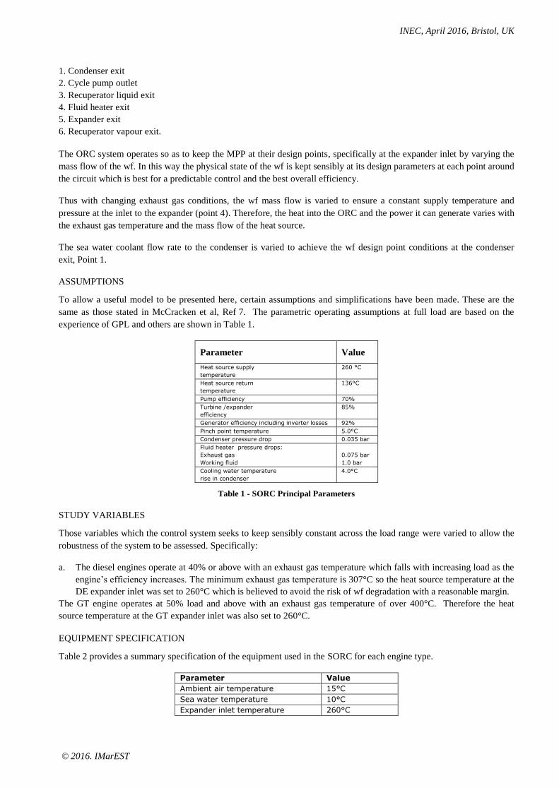
ASSUMPTIONS
To allow a useful model to be presented here, certain assumptions and simplifications have been made. These are the
same as those stated in McCracken et al, Ref 7. The parametric operating assumptions at full load are based on the
experience of GPL and others are shown in Table 1.
Parameter Value
Heat source supply
temperature
260 °C
Heat source return
temperature
136°C
Pump efficiency 70%
Turbine /expander
efficiency
85%
Generator efficiency including inverter losses 92%
Pinch point temperature 5.0°C
Condenser pressure drop 0.035 bar
Fluid heater pressure drops:
Exhaust gas
Working fluid
0.075 bar
1.0 bar
Cooling water temperature
rise in condenser
4.0°C
Table 1 - SORC Principal Parameters
STUDY VARIABLES
Those variables which the control system seeks to keep sensibly constant across the load range were varied to allow the
robustness of the system to be assessed. Specifically:
a. The diesel engines operate at 40% or above with an exhaust gas temperature which falls with increasing load as the
engine’s efficiency increases. The minimum exhaust gas temperature is 307°C so the heat source temperature at the
DE expander inlet was set to 260°C which is believed to avoid the risk of wf degradation with a reasonable margin.
The GT engine operates at 50% load and above with an exhaust gas temperature of over 400°C. Therefore the heat
source temperature at the GT expander inlet was also set to 260°C.
EQUIPMENT SPECIFICATION
Table 2 provides a summary specification of the equipment used in the SORC for each engine type.
Parameter Value
Ambient air temperature 15°C
Sea water temperature 10°C
Expander inlet temperature 260°C
INEC, April 2016, Bristol, UK
© 2016. IMarEST
Expander inlet pressure 80 bar
DE ORC efficiency 14.75%
GT ORC efficiency 17.8%
Table 2. Summary of SORC Principal Operating Parameters
TURBO-GENERATOR EXPANDER
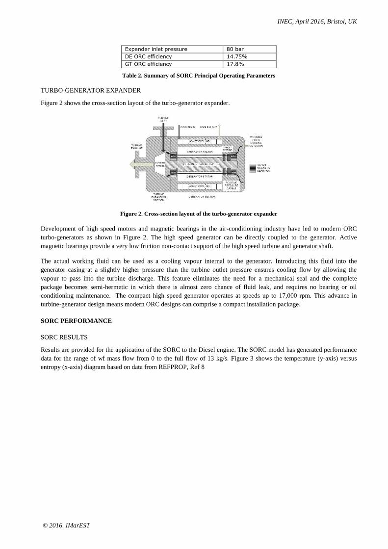
Figure 2 shows the cross-section layout of the turbo-generator expander.
Figure 2. Cross-section layout of the turbo-generator expander
Development of high speed motors and magnetic bearings in the air-conditioning industry have led to modern ORC
turbo-generators as shown in Figure 2. The high speed generator can be directly coupled to the generator. Active
magnetic bearings provide a very low friction non-contact support of the high speed turbine and generator shaft.
The actual working fluid can be used as a cooling vapour internal to the generator. Introducing this fluid into the
generator casing at a slightly higher pressure than the turbine outlet pressure ensures cooling flow by allowing the
vapour to pass into the turbine discharge. This feature eliminates the need for a mechanical seal and the complete
package becomes semi-hermetic in which there is almost zero chance of fluid leak, and requires no bearing or oil
conditioning maintenance. The compact high speed generator operates at speeds up to 17,000 rpm. This advance in
turbine-generator design means modern ORC designs can comprise a compact installation package.
SORC PERFORMANCE
SORC RESULTS
Results are provided for the application of the SORC to the Diesel engine. The SORC model has generated performance
data for the range of wf mass flow from 0 to the full flow of 13 kg/s. Figure 3 shows the temperature (y-axis) versus
entropy (x-axis) diagram based on data from REFPROP, Ref 8
INEC, April 2016, Bristol, UK
© 2016. IMarEST
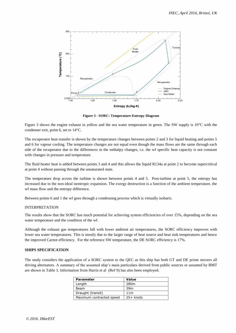
Figure 3 - SORC: Temperature-Entropy Diagram
Figure 3 shows the engine exhaust in yellow and the sea water temperature in green. The SW supply is 10°C with the
condenser exit, point 6, set to 14°C.
The recuperator heat transfer is shown by the temperature changes between points 2 and 3 for liquid heating and points 5
and 6 for vapour cooling. The temperature changes are not equal even though the mass flows are the same through each
side of the recuperator due to the differences in the enthalpy changes, i.e. the wf specific heat capacity is not constant
with changes in pressure and temperature.
The fluid heater heat is added between points 3 and 4 and this allows the liquid R134a at point 2 to become supercritical
at point 4 without passing through the unsaturated state.
The temperature drop across the turbine is shown between points 4 and 5. Post-turbine at point 5, the entropy has
increased due to the non-ideal isentropic expansion. The exergy destruction is a function of the ambient temperature, the
wf mass flow and the entropy difference.
Between points 6 and 1 the wf goes through a condensing process which is virtually isobaric.
INTERPRETATION
The results show that the SORC has much potential for achieving system efficiencies of over 15%, depending on the sea
water temperature and the condition of the wf.
Although the exhaust gas temperatures fall with lower ambient air temperatures, the SORC efficiency improves with
lower sea water temperatures. This is mostly due to the larger range of heat source and heat sink temperatures and hence
the improved Carnot efficiency. For the reference SW temperature, the DE SORC efficiency is 17%.
SHIPS SPECIFICATION
The study considers the application of a SORC system to the QEC as this ship has both GT and DE prime movers all
driving alternators. A summary of the assumed ship’s main particulars derived from public sources or assumed by BMT
are shown in Table 3. Information from Harris et al (Ref 9) has also been employed.
Parameter Value
Length 280m
Beam 39m
Draught (transit) 11m
Maximum contracted speed 25+ knots

INEC, April 2016, Bristol, UK
© 2016. IMarEST
Parameter Value
Endurance 10,000nm at 16 knots1
Displacement 70,600 tonnes
DE gensets 2 x 8,700 kWb +
2 x 11,600kWb
GT genset 2 in number
36,000kWb
Temperate SEL < 20 knots 15,000kWe 1
Temperate SEL >= 20 knots 16,500kWe 1
Temperate harbour load 12,000kWe 1
Table 3. Ships Main Particulars
Although it is understood the ship can go over 25 knots, this study limits the ship’s speed to 25 knots.
Figure 4 shows the assumed ship-speed operating profile as the percentage time at sea for each speed on the y-axis
versus ship speed (knots) on the x-axis.
Figure 4. Assumed ship-speed operating profile
Figure 4 shows how the ship is assumed to spend much of its time at low speeds with less time spent at 17 knots and
above when at least one of the GT gensets would be in operation.
Figure 5 shows the estimated engine loads across the whole speed range using a load-levelling approach whereby the
engines which provide the highest safe loading are used at a given total electrical load. The GT genset cuts-in at 17
knots.
1. BMT assumption
INEC, April 2016, Bristol, UK
© 2016. IMarEST
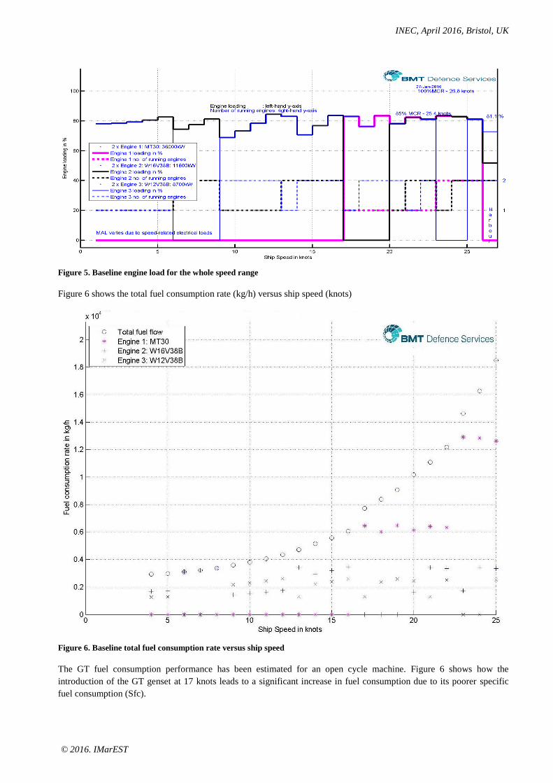
Figure 5. Baseline engine load for the whole speed range
Figure 6 shows the total fuel consumption rate (kg/h) versus ship speed (knots)
Figure 6. Baseline total fuel consumption rate versus ship speed
The GT fuel consumption performance has been estimated for an open cycle machine. Figure 6 shows how the
introduction of the GT genset at 17 knots leads to a significant increase in fuel consumption due to its poorer specific
fuel consumption (Sfc).

INEC, April 2016, Bristol, UK
© 2016. IMarEST
SHIP FIT
The body of the SORC plant comprises the fluid heater, the recuperator, the pump, condenser and turbine-generator.
The fluid heater would be located nearly in-line with the existing exhaust trunking, most likely in the uptake casing. The
remaining equipment would be installed lower down and ideally located on a common skid. However, the system
equipment can be spread apart from each other to utilise available space in a retrofit installation, although the extra
piping between the equipment will increase the total installed weight. As the fluid is non-flammable, it can be safely
installed in a machinery space.
A longer post-WHR exhaust gas ducting with cooler denser exhaust gas flows may lead to lower pressure drop and may
mitigate the pressure drop losses over the WHR unit.
Table 4 provides an estimate of the size and weight of the constituents parts of each SORC system.

INEC, April 2016, Bristol, UK
© 2016. IMarEST
Item Volumes – m3 Weight - tonnes
Small DE Large
DE
GT Small
DE
Large
DE
GT
Exhaust gas collector / fluid heater 11 14 103 8 8 45
SORC Recuperator 5 7 52 5 5 38
SORC Condenser 3 4 28 2 2 18
ORC Expander / Turbogenerator 1 2 62 2 4 35
SORC wf motor-pump 0 1 86 2 2 8
Inverter & control cabinet 6 7 02 2 3 0
SORC SW motor-pump 1 1 1 1 1 4
Other equipment 1 1 1 2 3 15
Totals 27 36 333 22 25 163
ORC Ratings - kWe 904 1,233 10,433
Table 4. Summary of SORC Systems
INSTALLED SORC PERFORMANCE
The refrigerant R134a was used as the wf for both the GT and the DE SORC systems with its temperature limited to
260°C . The ambient air temperature of 15°C allows the GT engine to operate with a performance at ISO conditions.
The diesel engines also operate at their ISO rating (usually specified at 25°C).
GT SORC
When a SORC system was applied to the GT engine exhaust system, the SORC is rated at 10,433 kWe. When taken
collectively as a single power genset package, the GT genset and its associated SORC provide the improved overall
specific Sfc shown in Figure 7.
Figure 7. GT engine Sfc characteristic combined with and without the SORC system
Figure 7 shows how the addition of the SORC system rated at 10,433kWe to the GT genset greatly reduces the fuel
required to generate each kW across the GT load range and also increases the total rated power.
2. Not required - synchronous generator

INEC, April 2016, Bristol, UK
© 2016. IMarEST
DIESEL SORC
Figure 8 shows the indicated Sfc characteristic of the Wartsila 16V38B genset (includes allowances for engine -driven
pumps) with and without the addition of the SORC, (Ref 10) .
Figure 8. Diesel engine Sfc with and without the SORC system
Figure 8 shows how the Wartsila 16V38B Sfc characteristic is also modified by the 1,233 kWe SORC system.
Figure 9 shows the total fuel consumption for all main engines across the ship’s speed range for:
The baseline ship
The addition of SORC to the GT genets only
The addition of SORC to the Diesel gensets only
The baseline ship with all main genset engines supplemented with an SORC system.
Figure 9. Comparative fuel consumption rates
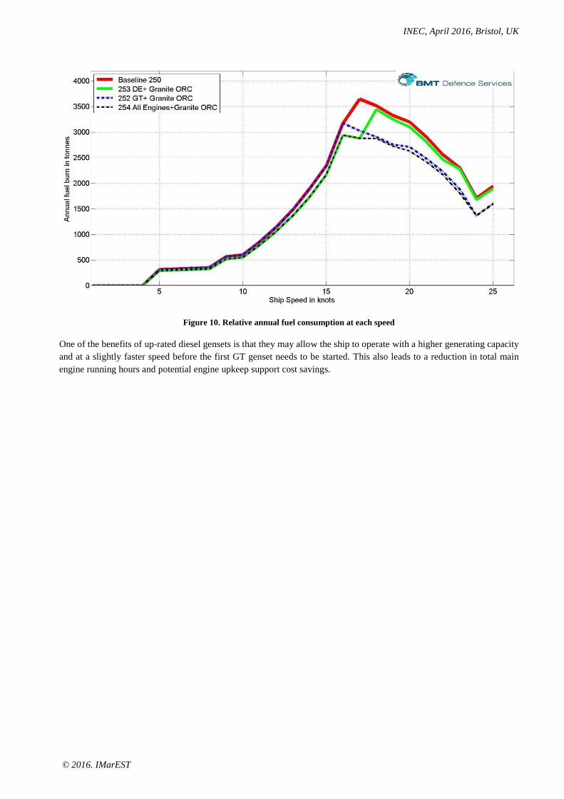
When the ship’s operating profile is taken into account Figure 10 shows the annual fuel consumption at each ship speed.
INEC, April 2016, Bristol, UK
© 2016. IMarEST
Figure 10. Relative annual fuel consumption at each speed
One of the benefits of up-rated diesel gensets is that they may allow the ship to operate with a higher generating capacity
and at a slightly faster speed before the first GT genset needs to be started. This also leads to a reduction in total main
engine running hours and potential engine upkeep support cost savings.
INEC, April 2016, Bristol, UK
© 2016. IMarEST
Option SORC Rating
kWe & % genset
MCR increase
Fuel
Saving
% pa
Sea-time Engine Running Hours pa
W12V38B W16V38B MT30
Baseline - 0.0 8,177 6,604 2,778
Diesels + SORC 12V – 904 -10%
16V – 1,233 – 6%
6.1 7,181 7,600 2,306
GT + SORC 10,433 – 29% 10.7 7,705 5,556 2,621
SORC on all
gensets
25,140 – 22.7% 14.8 7,286 6,238 2,149
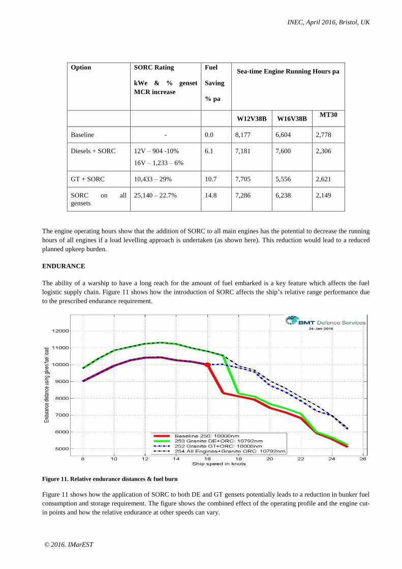
The engine operating hours show that the addition of SORC to all main engines has the potential to decrease the running
hours of all engines if a load levelling approach is undertaken (as shown here). This reduction would lead to a reduced
planned upkeep burden.
ENDURANCE
The ability of a warship to have a long reach for the amount of fuel embarked is a key feature which affects the fuel
logistic supply chain. Figure 11 shows how the introduction of SORC affects the ship’s relative range performance due
to the prescribed endurance requirement.
Figure 11. Relative endurance distances & fuel burn
Figure 11 shows how the application of SORC to both DE and GT gensets potentially leads to a reduction in bunker fuel
consumption and storage requirement. The figure shows the combined effect of the operating profile and the engine cut-
in points and how the relative endurance at other speeds can vary.

INEC, April 2016, Bristol, UK
© 2016. IMarEST
COSTS
Option SORC Rating
kWe & % genset
MCR increase
SORC
UPC
£m
Cost
onboard
£m
Payback
years
SORC for Diesel
engines
12V – 904 -10%
16V – 1,233 – 6%
6.411 6.411 7.53
SORC system for
GT engine
10,433 – 29% 28.169 2.000 10.0
SORC on all gensets 25,140 – 22.7% 34.58 8.411 10.37
Table 5. Costs and Payback
Ship-board installation costs for both SORC are difficult to estimate so they estimated to be comparable to the UPC of
the SORC systems.
The cost of fuel is £700/tonnes which leads to the payback periods stated in Table 5. These payback periods could be
reduced by:
The increasing cost of fuel - estimated to be ~1 year all options3;
The adoption of a lower SORC rating – ~6 months for all options;
Use alongside – 1 month for DE and all genset options.
CONCLUSIONS
The super-critical ORC technology with a standard refrigerant indicates useful and achievable annual fuel economy
savings of up to 14.8%. The technology does not require fine matching with the engine and can be retrofitted to the
ships providing there is sufficient space in the casing or other spaces through which the engine exhaust may pass.
The SORC technology allows a better machinery operating regime to be achieved with much lower exhaust
temperatures. The ship operates at a slightly higher speed prior to GT gensets being started.
The SORC technology benefits from the cooler sea water temperatures to be found in Northern European waters as this
allows a greater heat source to heat sink temperature range and thus a higher theoretical Carnot cycle efficiency.
The SORC system comprises individual units which can be located flexibly around the machinery rooms to
accommodate the total volume of the system.
This study has concentrated on the application of a SORC system to the QEC and shows that with an SORC fit to each
of the main diesel engines, a useful annual cost saving is achieved together with a payback of ~7.5 years. This figure is
very vulnerable to the definition of the operating profile and the operating sea water temperatures.
ACKNOWLEDGEMENTS
The authors wish to thank their respective companies for their permission to undertake this study. The findings and
conclusions are those of the authors alone. The information used in this study has been derived or drawn from public
sources. The results are therefore only broadly indicative of the performance of the QEC power and propulsion system.
3. Very speculative
INEC, April 2016, Bristol, UK
© 2016. IMarEST
REFERENCES
1 OpCon Marine. "Commissioning and testing of first reference installation of Opcon technology for ships "
2012.
2 Auld. A. "Organic Rankine cycles in waste heat recovery: a comparative study". 2013
3 Koeberlein D. Cummins SuperTruck programme: technology demonstrate of highly efficient clean, diesel-
powered Class 8 trucks. In: Directions in Engine Efficiency and Emissions Research Conference, Detroit,
USA. 2011 October.
4 Moghtaderi and Doroodchi. "An Overview of GRANEX Technology for Geothermal Power Generation and
Waste Heat Recovery". Australian Geothermal Energy Conference 2009.
5 Suarez de la Fuente et al. “Making shipping greener: ORC modelling under realistic operative conditions”.
Low carbon shipping conference. London 2013.
6 UK Defra Data Sources.
7 McCracken, S & Buckingham, J E. “The benefits of ship waste heat recovery using a supercritical organic
Rankine cycle”. RINA Energy Efficient Ship conference, Rotterdam, 4th
November 2015.
8 Lemmon, E.W., Huber, M.L., McLinden, M.O. NIST Standard Reference Database 23: Reference Fluid
Thermodynamic and Transport Properties-REFPROP, Version 9.1, National Institute of Standards and
Technology, Standard Reference Data Program, Gaithersburg, 2013.
9 Harris, A et al. “The hydrodynamic design of the Queen Elizabeth class aircraft carriers”. RINA Warships
2009 Airpower At Sea Conference
10 Wartsila 38B Project guide .2007