super precision bearings super precision... · super precision bearings ti-i-5003.2 / e ibc...
TRANSCRIPT
Super Precision Bearings
TI-I-5003.2 / E
IBC WÄLZLAGER GMBHINDUSTRIAL BEARINGS AND COMPONENTS
Post box 1825 · 35528 WETZLAR (GERMANY)
Tel: +49/64 41/95 53-02 Corporate officeFax: +49/64 41/5 30 15 Industriegebiet Oberbiel
D-35606 Solms-Oberbiel
e-mail: [email protected] http://www.ibc-waelzlager.com
IBC INDUSTRIAL BEARINGSAND COMPONENTS AG
Tel: +41/32/6 52 83 53 Corporate officeFax: +41/32/6 52 83 58 Kapellstrasse 26
CH-2540 Grenchen
e-mail: [email protected] http://www.ibc-waelzlager.com

More of IBC . . .
Company Profile(German)(English)
LieferprogrammHochgenauigkeits-Wälzlager
Präzisionslagereinheiten · PräzisionsspannmutternTI-I-5000.0 / D
Product RangeSuper Precision BearingsT1-I-5000.0 / D (German)T1-I-5000.0 / E (English)
Product RangePrice List
Schrägkugellager 40°TI-I-4044.0 / D
Angular Contact BallBearings 40°T1-1-4044.0 / D (German)T1-1-4044.0 / E (English)
Linear BearingsT1-1-7001.2 / D (German)
Telescopic RailsT1-1-7005.1 / D (German)
Super Precision BearingsService Catalog T1-1-5003.1 / D (German)T1-1-5003.2 / E (English)
IBC Wälzlager mit ATCoatBeschichtungTI-1-5010.2/D
ATCoated BearingsTI-1-5010.2 / D (German)
© Copyright 2006 IBC Wälzlager GmbH
The contents of this publication are the copyright of the publisher and may not be reproduced (even extracts)unless permission is granted. Every care has been taken to ensure the accuracy of the information containedin this publication but no liability can be accepted for any loss or damage whether direct, indirect or conse-quential arising out of the use of the information contained here in.
Wälzlager für KugelgewindetriebeAxial-Schrägkugellager 60°
Präzisionslagereinheiten · PräzisionsspannmutternTI-I-5010.2 / D
Ball Screw Support BearingsTI-I-5010.2 / D (German)TI-I-5010.2 / E (English)
Location with Tradition
The headquarters in Solms-Oberbielis centrally located in Germany close to the North/South and East/West highways whichalso provides for a central location in Europe.The international Airport Frankfurt approx.80 km away serves as a worldwide link.
Flexible and Reliable
In the middle of 1996 we opened the central computer controlled high shelf warehouse withmore than 2.000 pallet places.It is used for finsihed andsemi-finished products as wellas for large bearings.This is in addition to our existingtwo-storage computer controlledservice warehouse also with more than 2.500 storage places.
Both warehouse systemsprovide together with our distribution centre and communication network preciselogistics and a worldwideunequaled reliability.
Precision with Future . . .
We are future orientated.We have the creativity and vision to perform and provide.This is our exact presentation to solutions with precision.
Headquarter of the IBC Wälzlager GmbH at the industrial area of Solms-Oberbiel
Precise Logistics provide an unequaled worldwide reliability
New plant in Asslar
Central Computer Controlled High Shelf Warehouse – Middle 1996

IBC INDUSTRIAL BEARINGS AND COMPONENTS 3
1. Introduction
Permanent increase in demands on quality bearing sys-tems is leading on to new developments of various tech-nologies and new materials, to meet the high and veryspecific technical and economical fields of application.IBC is taking responsibility for this fact by continuousincrease in performance of products and technicalprocesses, as well as extension of product range.
IBC Wälzlager GmbH Industrial Bearings and Components,has more than 30 years experience in the field of bearingtechnologie. IBC continues the tradition of the 1918founded Robert Kling Wetzlar GmbH.
Close customer contacts based on fair dialogues andpartnership achieve common aims and objectives togetherwith our customers.
The very intensive cooperation with universities, not onlyin the field of research and development, but also practicaljob training is a traditional and essential part of the scien-tific work of IBC Wälzlager GmbH.
The innovation is reflected in the intensive activities ofresearch and development. As an example we point outthe material variation of bearing components as a con-tributing factor to increase the efficiency of our products.This combination of research and controlled processes isleading to high precision bearings.
At the very first beginning special applications have beenthe cause of hybrid ball bearings, and nowadays thesebelong to our standard programme for the machine tooland electric motor industry.
Modified materials for cages, as PEEK are used forhigh-speed precision bearings and for high temperatureapplications.
Lubricated high precision bearings, completed with sealedversions allow for maintenance free operation with lifetimelubrication. This makes a valuable contribution towardseasy mounting and design.
The IBC Wälzlager GmbH delivery programme isenhanced by ATCoat thin dense chromium coated highprecision bearings for special applications. Prolongationof usage, reduced wear and friction as well as reasonablecorrosion protection are the main value-added benefits ofATCoat high precision bearings.
The following pages of this catalogue are showing the vari-ety of products of high precision angular contact ball bear-ings (spindle bearings), high precision cylindrical rollerbearings, high precision single row deep groove ball bear-ings, completed by precision rolling bearings of specialdesign, i. e. for turbo charger bearings, compressors, sep-arators and vacuum pumps.
Depending on application high precision angular contactball bearings can be delivered with contact angle 15°, 25°,30°, 35°, 40° or 60°, with different diameters of balls out ofsteel or ceramic, open or sealed. Direct lubrication by theouter ring is another possible variation.The most convenient bearings can be chosen dependingon the requirements regarding rotational speed, loadcapacity, rigidity, and lubrication as well as any further sur-rounding parameters.
Many different and innovative principles granting a safefloating bearing function can be found in IBC’s productrange. Not only high precision cylindrical roller bearingswith its constructive floating function, but also the springloaded high precision deep groove ball bearings and highprecision angular contact ball bearings are worth mention-ing. Bearings with ATCoat are representing an alternativeto avoid fretting corrosion and to grant a slide fit.
Further components of the bearing systems like precisionlocknuts and labyrinth seals are essential parts of theIBC’s delivery programme for many years. They are mainlyused for preloading of spindle and ball screw supportbearings. A large variety of designs and dimensionsimplies an optimization of economical efficiency for theusers.
Further more IBC is producing an extensive programme ofprecision flange and pillow block units. In addition to thestandard design IBC is offering a large number of specialcustomized solutions.
Our quality management system is implemented andaccredited according DIN EN ISO 9001: 2000 for design,development, production and sales of all kinds of rollingbearings and linear motion bearings.
For any further details regarding the different bearing sys-tems as well as how to select the right bearing for safeintegration in your individual design, please refer to ourcorresponding catalogues and brochures. An overview isindicated on the last page.
With this extensive delivery programme, you will find anappropriate IBC high precision bearing for your specialapplication. For further details, our technical department ispleased to be of your assistance and support at any time.

2. IBC Precision Products
4 IBC WÄLZLAGER GMBH
Series Designation Page
Super Precision Angular Contact 5Ball Bearings (Spindle Bearings)
Hybrid Bearings 7Coated BearingsMatched Sets of Bearings
40° Angular Contact Ball Bearings 19
Single Row Deep Groove Ball Bearings 24
Super Precision Cylindrical Roller Bearings 30
Thrust Ball Bearings 40
60° Super Precision Angular Contact 44Thrust Ball Bearings
Super Precision Bearing Units with 60° 49Angular Contact Thrust Ball Bearings andFloating End Supporting Units
Super Precision Pillow Block Bearing Units 52
Super Precision Locknuts and Labyrinth Seals 59
ATCoated Bearings; Cage versions 65
Tolerances, Gradings, Fits, BearLub Greases 68
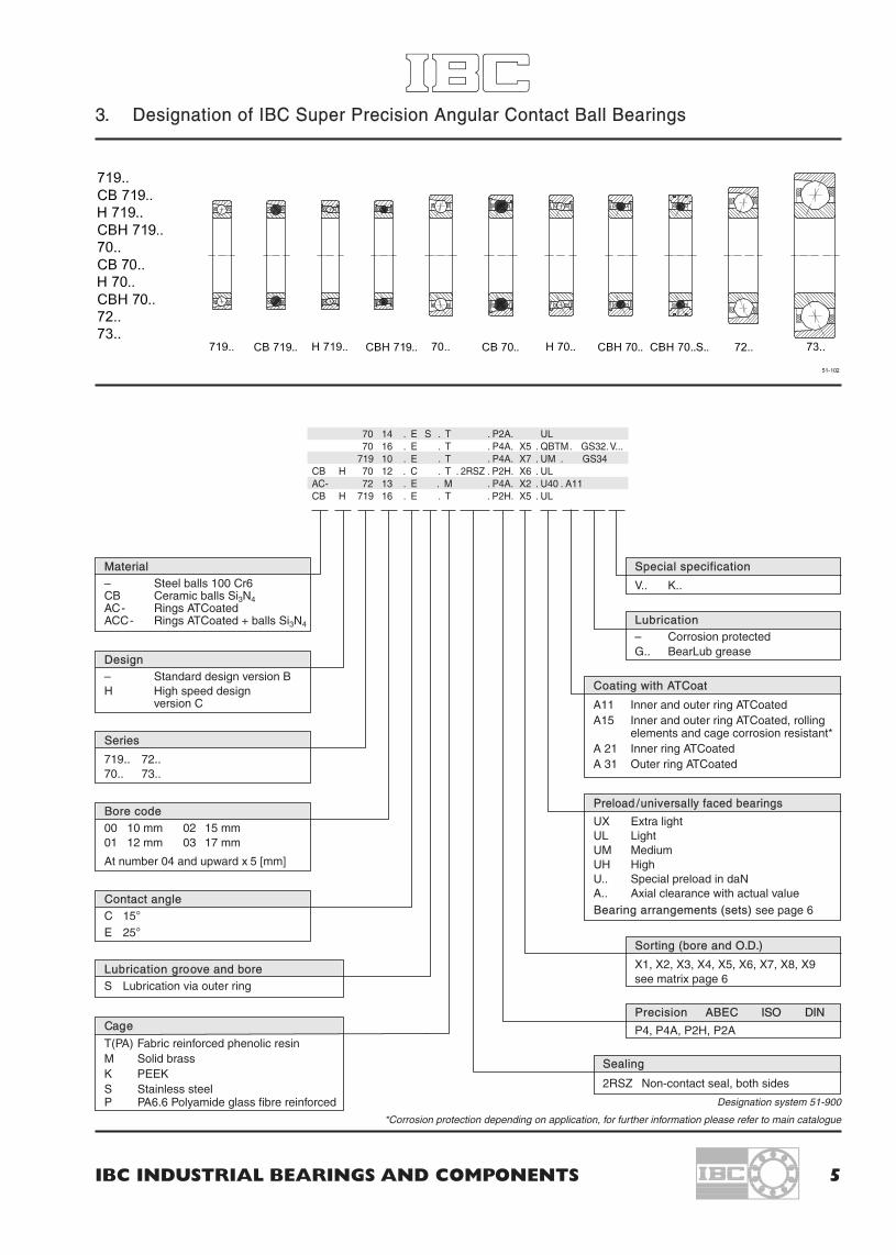
3. Designation of IBC Super Precision Angular Contact Ball Bearings
IBC INDUSTRIAL BEARINGS AND COMPONENTS 5
70 14 . E S . T . P2A. UL70 16 . E . T . P4A. X5 . QBTM. GS32.V...
719 10 . E . T . P4A. X7 . UM . GS34CB H 70 12 . C . T . 2RSZ . P2H. X6 . ULAC- 72 13 . E . M . P4A. X2 . U40 . A11CB H 719 16 . E . T . P2H. X5 . UL
Material– Steel balls 100 Cr6CB Ceramic balls Si3N4AC- Rings ATCoatedACC- Rings ATCoated + balls Si3N4
Special specification
V.. K..
Sorting (bore and O.D.)
X1, X2, X3, X4, X5, X6, X7, X8, X9see matrix page 6
Sealing
2RSZ Non-contact seal, both sides
Lubrication– Corrosion protectedG.. BearLub grease
Coating with ATCoat
A11 Inner and outer ring ATCoatedA15 Inner and outer ring ATCoated, rolling
elements and cage corrosion resistant*A 21 Inner ring ATCoatedA 31 Outer ring ATCoated
Precision ABEC ISO DIN
P4, P4A, P2H, P2A
Preload /universally faced bearings
UX Extra lightUL LightUM MediumUH HighU.. Special preload in daNA.. Axial clearance with actual valueBearing arrangements (sets) see page 6
Design– Standard design version BH High speed design
version C
Series
719.. 72..70.. 73..
Contact angleC 15°E 25°
Cage
T(PA) Fabric reinforced phenolic resinM Solid brassK PEEKS Stainless steelP PA6.6 Polyamide glass fibre reinforced
Bore code00 10 mm 02 15 mm01 12 mm 03 17 mm
At number 04 and upward x 5 [mm]
Lubrication groove and boreS Lubrication via outer ring
Designation system 51-900
*Corrosion protection depending on application, for further information please refer to main catalogue

6 IBC WÄLZLAGER GMBH
3.1 Production Range of IBC Precision Angular Contact Ball Bearings
Production series
719... H 719... 70... H 70... 72... 73...
d D B D B D B D B D B D Bmm mm DI* mm DI* mm DI* mm DI* mm DI* mm
10 71900 22 6 7000 26 8 7200 30 9 •12 71901 24 6 7001 28 8 7201 32 10 •15 71902 28 7 7002 32 9 7202 35 11 •17 71903 30 7 7003 35 10 7203 40 12 •20 71904 37 9 7004 42 12 7204 47 14 • 7304 52 1525 71905 42 9 • H 71905 42 9 • 7005 47 12 • H 7005 47 12 • 7205 52 15 • 7305 62 1730 71906 47 9 • H 71906 47 9 • 7006 55 13 • H 7006 55 13 • 7206 62 16 • 7306 72 1935 71907 55 10 • H 71907 55 10 • 7007 62 14 • H 7007 62 14 • 7207 72 17 • 7307 80 2140 71908 62 12 • H 71908 62 12 • 7008 68 15 • H 7008 68 15 • 7208 80 18 • 7308 90 2345 71909 68 12 • H 71909 68 12 • 7009 75 16 • H 7009 75 16 • 7209 85 19 • 7309 100 2550 71910 72 12 • H 71910 72 12 • 7010 80 16 • H 7010 80 16 • 7210 90 20 • 7310 110 2755 71911 80 13 • H 71911 80 13 • 7011 90 18 • H 7011 90 18 • 7211 100 21 • 7311 120 2960 71912 85 13 • H 71912 85 13 • 7012 95 18 • H 7012 95 18 • 7212 110 22 • 7312 130 3165 71913 90 13 • H 71913 90 13 • 7013 100 18 • H 7013 100 18 • 7213 120 23 7313 140 3370 71914 100 16 • H 71914 100 16 • 7014 110 20 • H 7014 110 20 • 7214 125 24 7314 150 3575 71915 105 16 • H 71915 105 16 • 7015 115 20 • H 7015 115 20 • 7215 130 25 7315 160 3780 71916 110 16 • H 71916 110 16 • 7016 125 22 • H 7016 125 22 • 7216 140 2685 71917 120 18 • H 71917 120 18 • 7017 130 22 • H 7017 130 22 • 7217 150 2890 71918 125 18 • H 71918 125 18 • 7018 140 24 • H 7018 140 24 • 7218 160 3095 71919 130 18 • H 71919 130 18 • 7019 145 24 • H 7019 145 24 • 7219 170 32
100 71920 140 20 • H 71920 140 20 • 7020 150 24 • H 7020 150 24 • 7220 180 34105 71921 145 20 H 71921 145 20 7021 160 26 H 7021 160 26 7221 190 36110 71922 150 20 H 71922 150 20 7022 170 28 H 7022 170 28 7222 200 38120 71924 165 22 H 71924 165 22 7024 180 28 H 7024 180 28 7224 215 40130 71926 180 24 7026 200 33 7226 230 40140 71928 190 24 7028 210 33 7228 250 42150 71930 210 28 7030 225 35160 71932 220 28 7032 240 38170 71934 230 28 7034 260 42180 71936 250 33 7036 280 46190 71938 260 33 7038 290 46200 71940 280 38 7040 310 51220 71944 300 38240 71948 320 38260 71952 360 46280 71956 380 46
Table 14-302: Production Range of IBC Precision Angular Contact Ball Bearings *DI: sealed version
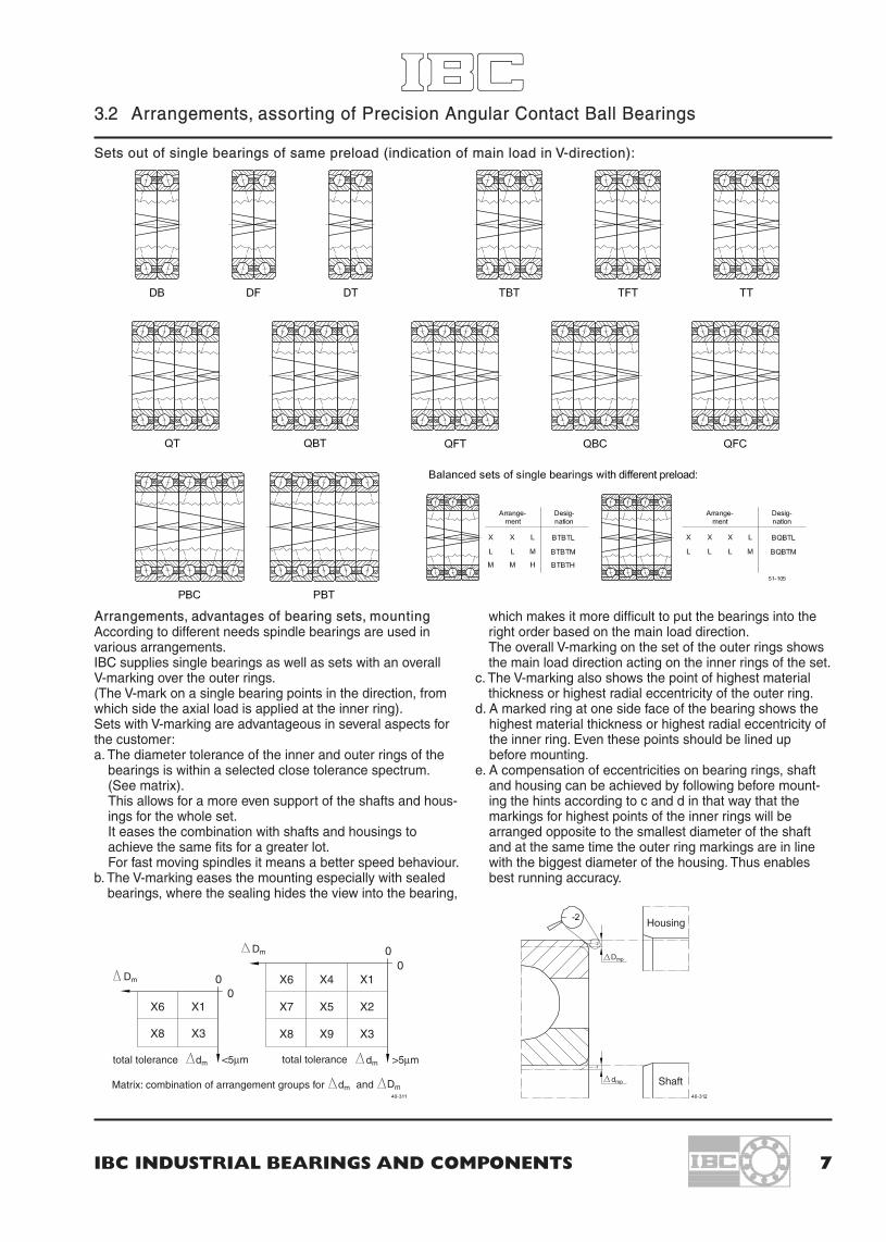
3.2 Arrangements, assorting of Precision Angular Contact Ball Bearings
IBC INDUSTRIAL BEARINGS AND COMPONENTS 7
total tolerance total tolerance
Matrix: combination of arrangement groups for and
Housing
Shaft
Dm
Dm
dm <5µm >5µmdm
dm Dm
Dmp
dmp
Sets out of single bearings of same preload (indication of main load in V-direction):
Arrangements, advantages of bearing sets, mountingAccording to different needs spindle bearings are used invarious arrangements.IBC supplies single bearings as well as sets with an overallV-marking over the outer rings.(The V-mark on a single bearing points in the direction, fromwhich side the axial load is applied at the inner ring).Sets with V-marking are advantageous in several aspects forthe customer:a. The diameter tolerance of the inner and outer rings of the
bearings is within a selected close tolerance spectrum.(See matrix).This allows for a more even support of the shafts and hous-ings for the whole set.It eases the combination with shafts and housings toachieve the same fits for a greater lot.For fast moving spindles it means a better speed behaviour.
b. The V-marking eases the mounting especially with sealedbearings, where the sealing hides the view into the bearing,
which makes it more difficult to put the bearings into theright order based on the main load direction.The overall V-marking on the set of the outer rings showsthe main load direction acting on the inner rings of the set.
c. The V-marking also shows the point of highest materialthickness or highest radial eccentricity of the outer ring.
d. A marked ring at one side face of the bearing shows thehighest material thickness or highest radial eccentricity ofthe inner ring. Even these points should be lined upbefore mounting.
e. A compensation of eccentricities on bearing rings, shaftand housing can be achieved by following before mount-ing the hints according to c and d in that way that themarkings for highest points of the inner rings will bearranged opposite to the smallest diameter of the shaftand at the same time the outer ring markings are in linewith the biggest diameter of the housing. Thus enablesbest running accuracy.
X4 X1X6
X5 X2X7X6 X1
X8 X3 X9 X3X8
00
00

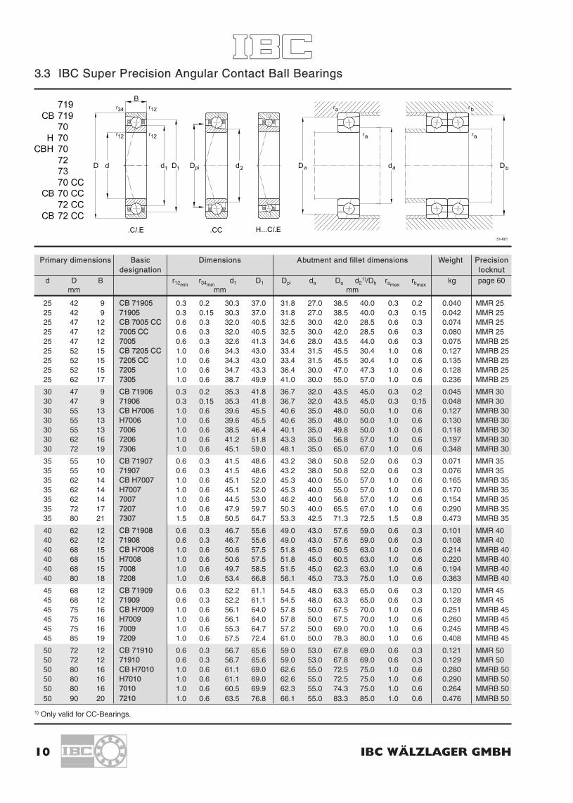
3.3 IBC Super Precision Angular Contact Ball Bearings
8 IBC WÄLZLAGER GMBH
Primary dimensions Basic Dimensions Abutment and fillet dimensions Weight Precisiondesignation locknut
d D B r12minr34min
d1 D1 Dpi da Da d21)/Db ramax
rbmaxkg page 60
mm mm mm
8 22 7 708 CC 0.3 0.15 12.8 17.5 12.7 11.0 19.5 10.8 0.3 0.15 0.015 MMR 89 24 7 709 CC 0.3 0.15 14.3 19.0 14.2 12.5 21.0 12.4 0.3 0.15 0.018 MMR 9
10 22 6 71900 0.3 0.15 14.0 18.1 14.8 12.5 19.5 20.9 0.3 0.15 0.010 MMR 1010 26 8 CB 7000 CC 0.3 0.15 15.3 21.0 15.2 13.0 23.0 13.0 0.3 0.15 0.019 MMR 1010 26 8 7000 CC 0.3 0.15 15.3 21.0 15.2 13.0 23.0 13.0 0.3 0.15 0.020 MMR 1010 26 8 7000 0.3 0.15 14.7 21.4 16.5 12.0 22.7 24.0 0.3 0.15 0.019 MMRB 1010 30 9 CB 7200 CC 0.6 0.3 17.3 23.0 16.3 14.5 25.5 15.0 0.6 0.3 0.028 MMR 1010 30 9 7200 CC 0.6 0.3 17.3 23.0 16.3 14.5 25.5 15.0 0.6 0.3 0.030 MMR 10
12 24 6 71901 0.3 0.15 15.8 20.2 16.7 14.5 21.5 22.7 0.3 0.15 0.011 MMR 1212 28 8 CB 7001 CC 0.3 0.15 17.3 23.0 17.2 15.0 25.0 15.0 0.3 0.15 0.024 MMR 1212 28 8 7001 CC 0.3 0.15 17.3 23.0 17.2 15.0 25.0 15.0 0.3 0.15 0.025 MMR 1212 28 8 7001 0.3 0.15 16.7 23.4 18.5 14.0 24.7 26.0 0.3 0.15 0.020 MMRB 1212 32 10 CB 7201 CC 0.6 0.3 19.3 25.0 18.4 16.5 27.5 16.8 0.6 0.3 0.038 MMR 1212 32 10 7201 CC 0.6 0.3 19.3 25.0 18.4 16.5 27.5 16.8 0.6 0.3 0.040 MMR 1212 32 10 7201 0.6 0.3 18.3 26.1 20.4 15.0 27.9 29.0 0.6 0.3 0.035 MMRB 12
15 28 7 71902 0.3 0.15 19.2 23.8 20.3 17.5 25.5 26.7 0.3 0.15 0.016 MMR 1515 32 9 CB 7002 CC 0.3 0.15 20.8 26.5 20.7 18.5 28.5 18.5 0.3 0.15 0.028 MMR 1515 32 9 7002 CC 0.3 0.15 20.8 26.5 20.7 18.5 28.5 18.5 0.3 0.15 0.030 MMR 1515 32 9 7002 0.3 0.15 20.2 26.9 21.9 17.0 28.2 30.0 0.3 0.15 0.029 MMRB 1515 35 11 CB 7202 CC 0.6 0.3 22.3 28.0 21.3 19.5 28.2 30.0 0.6 0.3 0.048 MMR 1515 35 11 7202 CC 0.6 0.3 22.3 28.0 21.3 19.5 30.5 19.8 0.6 0.3 0.050 MMR 1515 35 11 7202 0.6 0.3 21.1 29.1 23.4 18.0 31.0 32.0 0.6 0.3 0.043 MMRB 15
17 30 7 CB 71903 0.3 0.15 20.8 26.3 22.2 19.0 27.5 28.0 0.3 0.15 0.016 MMR 1717 30 7 71903 0.3 0.15 20.8 26.3 22.2 19.0 27.5 28.0 0.3 0.15 0.017 MMR 1717 35 10 CB 7003 CC 0.3 0.15 22.9 29.5 23.1 21.0 31.0 20.2 0.3 0.15 0.037 MMR 1717 35 10 7003 CC 0.3 0.15 22.9 29.5 23.1 21.0 31.0 20.2 0.3 0.15 0.040 MMR 1717 35 10 7003 0.3 0.15 22.7 29.4 24.4 19.0 30.7 33.0 0.3 0.15 0.039 MMRB 1717 40 12 CB 7203 CC 0.6 0.3 25.4 32.0 24.3 22.5 34.5 22.4 0.6 0.3 0.067 MMR 1717 40 12 7203 CC 0.6 0.3 25.4 32.0 24.3 22.5 34.5 22.4 0.6 0.3 0.070 MMR 1717 40 12 7203 0.6 0.3 24.1 33.0 26.5 20.0 35.0 37.0 1.0 0.3 0.063 MMRB 17
20 37 9 CB 71904 0.3 0.15 25.3 31.8 26.7 22.0 33.5 35.0 0.3 0.15 0.034 MMR 2020 37 9 71904 0.3 0.15 25.3 31.8 26.7 22.0 33.5 35.0 0.3 0.15 0.036 MMR 2020 42 12 CB 7004 CC 0.6 0.3 27.0 35.5 27.5 25.0 37.0 23.4 0.6 0.3 0.065 MMR 2020 42 12 7004 CC 0.6 0.3 27.0 35.5 27.5 25.0 37.0 23.4 0.6 0.3 0.070 MMR 2020 42 12 7004 0.6 0.3 26.6 35.5 29.0 23.0 37.8 39.0 0.6 0.3 0.065 MMRB 2020 47 14 CB 7204 CC 1.0 0.6 29.9 37.5 28.8 26.5 40.5 26.6 1.0 0.6 0.106 MMRB 2020 47 14 7204 CC 1.0 0.6 29.9 37.5 28.8 26.5 40.5 26.6 1.0 0.6 0.110 MMRB 2020 47 14 7204 1.0 0.6 29.2 37.9 31.0 25.0 41.8 42.0 1.0 0.6 0.106 MMRB 2020 52 15 7304 1.0 0.6 29.6 41.1 30.9 25.0 45.3 47.0 1.0 0.6 0.144 MMRB 20
1) Only valid for CC-Bearings.

IBC INDUSTRIAL BEARINGS AND COMPONENTS 9
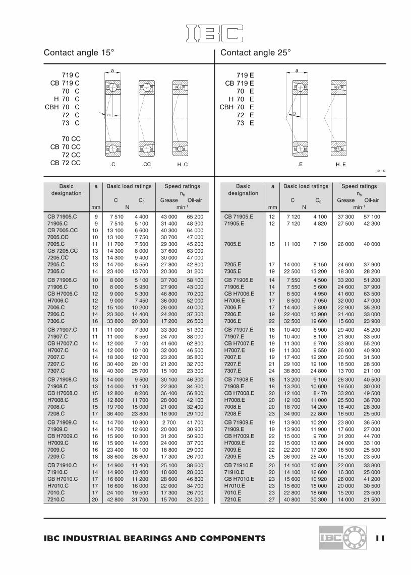
Contact angle 15° Contact angle 25°
Basic a Basic load ratings Speed ratingsdesignation nb
C C0 Grease Oil-airmm N min-1
708.CC 5 3 600 1 540 84 000 135 000
709.CC 5 3 900 1 800 79 000 127 000
71900.C 5 3 100 1 600 70 000 111 000CB 7000.CC 6 4 950 2 250 80 000 145 8007000.CC 6 4 950 2 250 68 000 108 0007000.C 6 5 710 2 770 57 000 88 000CB 7200.CC 7 5 850 2 950 72 500 123 0007200.CC 7 5 850 2 950 60 800 93 000
71901.C 5 3 300 1 800 60 000 86 000CB 7001.CC 6 5 450 2 600 72 500 119 0007001.CC 6 5 450 2 600 57 000 88 0007001.C 7 6 180 3 180 52 000 80 000CB 7201.CC 8 6 300 3 450 72 500 106 0007201.CC 8 6 300 3 450 51 000 79 0007201.C 8 8 600 4 320 47 000 72 500
71902.C 6 4 700 2 700 50 000 75 000CB 7002.CC 7 6 300 3 400 61 000 100 0007002.CC 7 6 300 3 400 48 700 75 0007002.C 8 6 970 4 010 44 200 68 000CB 7202.CC 9 6 300 3 450 58 000 94 0007202.CC 9 6 300 3 450 45 700 70 0007202.C 9 9 370 5 050 41 600 64 000
CB 71903.C 7 4 740 2 710 59 700 91 80071903.C 7 4 900 2 900 44 200 68 000CB 7003.CC 8 8 300 4 550 58 000 90 0007003.CC 8 8 300 4 550 47 000 75 0007003.C 9 7 320 4 440 39 600 61 000CB 7203.CC 10 8 300 4 700 50 800 83 0007203.CC 10 8 300 4 700 40 000 61 0007203.C 10 11 600 6 400 36 400 56 000
CB 71904.C 8 6 940 4 240 49 100 75 60071904.C 8 6 940 4 240 36 400 56 000CB 7004.CC 9 12 200 6 650 46 000 72 0007004.CC 9 12 200 6 650 34 700 53 0007004.C 10 9 830 5 450 33 100 51 000CB 7204.CC 11 10 600 6 200 43 000 71 0007204.CC 11 10 600 6 200 34 000 53 0007204.C 12 13 600 7 250 31 300 48 3007304.C 12 17 100 8 750 24 700 38 000
Basic a Basic load ratings Speed ratingsdesignation nb
C C0 Grease Oil-airmm N min-1
71900.E 5 2 900 1 500 63 000 96 000
7000.E 8 5 520 2 670 47 400 73 000
71901.E 5 3 100 1 700 57 000 85 000
7001.E 9 5 940 3 070 43 000 66 000
7201.E 10 8 320 4 190 39 200 60 000
71902.E 6 4 500 2 500 49 000 71 000
7002.E 10 6 670 3 830 36 400 56 000
7202.E 12 9 010 4 880 34 800 53 500
CB 71903.E 9 4 510 2 590 49 700 76 30071903.E 9 4 510 2 900 36 800 56 500
7003.E 11 6 980 4 250 33 700 51 000
7203.E 13 11 100 6 200 31 000 47 700
CB 71904.E 11 6 600 4 050 41 900 64 40071904.E 11 6 600 4 050 31 000 47 700
7004.E 13 9 400 5 200 29 300 45 100
7204.E 15 13 000 7 000 27 500 42 3007304.E 16 16 500 8 500 22 300 34 300
3.3 IBC Super Precision Angular Contact Ball Bearings
10 IBC WÄLZLAGER GMBH
Primary dimensions Basic Dimensions Abutment and fillet dimensions Weight Precisiondesignation locknut
d D B r12minr34min
d1 D1 Dpi da Da d21)/Db ramax
rbmaxkg page 60
mm mm mm
25 42 9 CB 71905 0.3 0.2 30.3 37.0 31.8 27.0 38.5 40.0 0.3 0.2 0.040 MMR 2525 42 9 71905 0.3 0.15 30.3 37.0 31.8 27.0 38.5 40.0 0.3 0.15 0.042 MMR 2525 47 12 CB 7005 CC 0.6 0.3 32.0 40.5 32.5 30.0 42.0 28.5 0.6 0.3 0.074 MMR 2525 47 12 7005 CC 0.6 0.3 32.0 40.5 32.5 30.0 42.0 28.5 0.6 0.3 0.080 MMR 2525 47 12 7005 0.6 0.3 32.6 41.3 34.6 28.0 43.5 44.0 0.6 0.3 0.075 MMRB 2525 52 15 CB 7205 CC 1.0 0.6 34.3 43.0 33.4 31.5 45.5 30.4 1.0 0.6 0.127 MMRB 2525 52 15 7205 CC 1.0 0.6 34.3 43.0 33.4 31.5 45.5 30.4 1.0 0.6 0.135 MMRB 2525 52 15 7205 1.0 0.6 34.7 43.3 36.4 30.0 47.0 47.3 1.0 0.6 0.128 MMRB 2525 62 17 7305 1.0 0.6 38.7 49.9 41.0 30.0 55.0 57.0 1.0 0.6 0.236 MMRB 25
30 47 9 CB 71906 0.3 0.2 35.3 41.8 36.7 32.0 43.5 45.0 0.3 0.2 0.045 MMR 3030 47 9 71906 0.3 0.15 35.3 41.8 36.7 32.0 43.5 45.0 0.3 0.15 0.048 MMR 3030 55 13 CB H7006 1.0 0.6 39.6 45.5 40.6 35.0 48.0 50.0 1.0 0.6 0.127 MMRB 3030 55 13 H7006 1.0 0.6 39.6 45.5 40.6 35.0 48.0 50.0 1.0 0.6 0.130 MMRB 3030 55 13 7006 1.0 0.6 38.5 46.4 40.1 35.0 49.8 50.0 1.0 0.6 0.118 MMRB 3030 62 16 7206 1.0 0.6 41.2 51.8 43.3 35.0 56.8 57.0 1.0 0.6 0.197 MMRB 3030 72 19 7306 1.0 0.6 45.1 59.0 48.1 35.0 65.0 67.0 1.0 0.6 0.348 MMRB 30
35 55 10 CB 71907 0.6 0.3 41.5 48.6 43.2 38.0 50.8 52.0 0.6 0.3 0.071 MMR 3535 55 10 71907 0.6 0.3 41.5 48.6 43.2 38.0 50.8 52.0 0.6 0.3 0.076 MMR 3535 62 14 CB H7007 1.0 0.6 45.1 52.0 45.3 40.0 55.0 57.0 1.0 0.6 0.165 MMRB 3535 62 14 H7007 1.0 0.6 45.1 52.0 45.3 40.0 55.0 57.0 1.0 0.6 0.170 MMRB 3535 62 14 7007 1.0 0.6 44.5 53.0 46.2 40.0 56.8 57.0 1.0 0.6 0.154 MMRB 3535 72 17 7207 1.0 0.6 47.9 59.7 50.3 40.0 65.5 67.0 1.0 0.6 0.290 MMRB 3535 80 21 7307 1.5 0.8 50.5 64.7 53.3 42.5 71.3 72.5 1.5 0.8 0.473 MMRB 35
40 62 12 CB 71908 0.6 0.3 46.7 55.6 49.0 43.0 57.6 59.0 0.6 0.3 0.101 MMR 4040 62 12 71908 0.6 0.3 46.7 55.6 49.0 43.0 57.6 59.0 0.6 0.3 0.108 MMR 4040 68 15 CB H7008 1.0 0.6 50.6 57.5 51.8 45.0 60.5 63.0 1.0 0.6 0.214 MMRB 4040 68 15 H7008 1.0 0.6 50.6 57.5 51.8 45.0 60.5 63.0 1.0 0.6 0.220 MMRB 4040 68 15 7008 1.0 0.6 49.7 58.5 51.5 45.0 62.3 63.0 1.0 0.6 0.194 MMRB 4040 80 18 7208 1.0 0.6 53.4 66.8 56.1 45.0 73.3 75.0 1.0 0.6 0.363 MMRB 40
45 68 12 CB 71909 0.6 0.3 52.2 61.1 54.5 48.0 63.3 65.0 0.6 0.3 0.120 MMR 4545 68 12 71909 0.6 0.3 52.2 61.1 54.5 48.0 63.3 65.0 0.6 0.3 0.128 MMR 4545 75 16 CB H7009 1.0 0.6 56.1 64.0 57.8 50.0 67.5 70.0 1.0 0.6 0.251 MMRB 4545 75 16 H7009 1.0 0.6 56.1 64.0 57.8 50.0 67.5 70.0 1.0 0.6 0.260 MMRB 4545 75 16 7009 1.0 0.6 55.3 64.7 57.2 50.0 69.0 70.0 1.0 0.6 0.245 MMRB 4545 85 19 7209 1.0 0.6 57.5 72.4 61.0 50.0 78.3 80.0 1.0 0.6 0.408 MMRB 45
50 72 12 CB 71910 0.6 0.3 56.7 65.6 59.0 53.0 67.8 69.0 0.6 0.3 0.121 MMR 5050 72 12 71910 0.6 0.3 56.7 65.6 59.0 53.0 67.8 69.0 0.6 0.3 0.129 MMR 5050 80 16 CB H7010 1.0 0.6 61.1 69.0 62.6 55.0 72.5 75.0 1.0 0.6 0.280 MMRB 5050 80 16 H7010 1.0 0.6 61.1 69.0 62.6 55.0 72.5 75.0 1.0 0.6 0.290 MMRB 5050 80 16 7010 1.0 0.6 60.5 69.9 62.3 55.0 74.3 75.0 1.0 0.6 0.264 MMRB 5050 90 20 7210 1.0 0.6 63.5 76.8 66.1 55.0 83.3 85.0 1.0 0.6 0.476 MMRB 50
1) Only valid for CC-Bearings.
IBC INDUSTRIAL BEARINGS AND COMPONENTS 11
Contact angle 15° Contact angle 25°
Basic a Basic load ratings Speed ratingsdesignation nb
C C0 Grease Oil-airmm N min-1
CB 71905.C 9 7 510 4 400 43 000 65 20071905.C 9 7 510 5 100 31 400 48 300CB 7005.CC 10 13 100 6 600 40 300 64 0007005.CC 10 13 100 7 750 30 700 47 0007005.C 11 11 700 7 500 29 300 45 200CB 7205.CC 13 14 300 8 000 37 600 63 0007205.CC 13 14 300 9 400 30 000 47 0007205.C 13 14 700 8 550 27 800 42 8007305.C 14 23 400 13 700 20 300 31 200
CB 71906.C 10 8 000 5 100 37 700 58 10071906.C 10 8 000 5 950 27 900 43 000CB H7006.C 12 9 000 5 300 46 800 70 200H7006.C 12 9 000 7 450 36 000 52 0007006.C 12 15 100 10 200 26 000 40 0007206.C 14 23 300 14 400 24 200 37 3007306.C 16 33 800 20 300 17 200 26 500
CB 71907.C 11 11 000 7 300 33 300 51 30071907.C 11 11 000 8 550 24 700 38 000CB H7007.C 14 12 000 7 100 41 600 62 800H7007.C 14 12 000 10 100 32 000 46 5007007.C 14 18 300 12 700 23 200 35 8007207.C 16 30 400 20 100 21 200 32 7007307.C 18 40 300 25 700 15 100 23 300
CB 71908.C 13 14 000 9 500 30 100 46 30071908.C 13 14 000 11 100 22 300 34 300CB H7008.C 15 12 800 8 200 36 400 56 800H7008.C 15 12 800 11 700 28 000 42 1007008.C 15 19 700 15 000 21 000 32 4007208.C 17 36 400 23 800 18 900 29 100
CB 71909.C 14 14 700 10 800 2 700 41 70071909.C 14 14 700 12 600 20 000 30 900CB H7009.C 16 15 900 10 300 31 200 50 900H7009.C 16 15 900 14 600 24 000 37 7007009.C 16 23 400 18 100 18 800 29 0007209.C 18 38 600 26 600 17 300 26 700
CB 71910.C 14 14 900 11 400 25 100 38 60071910.C 14 14 900 13 400 18 600 28 600CB H7010.C 17 16 600 11 200 28 600 46 800H7010.C 17 16 600 16 000 22 000 34 7007010.C 17 24 100 19 500 17 300 26 7007210.C 20 42 800 31 700 15 700 24 200
Basic a Basic load ratings Speed ratingsdesignation nb
C C0 Grease Oil-airmm N min-1
CB 71905.E 12 7 120 4 100 37 300 57 10071905.E 12 7 120 4 820 27 500 42 300
7005.E 15 11 100 7 150 26 000 40 000
7205.E 17 14 000 8 150 24 600 37 9007305.E 19 22 500 13 200 18 300 28 200
CB 71906.E 14 7 550 4 500 33 200 51 20071906.E 14 7 550 5 600 24 600 37 900CB H7006.E 17 8 500 4 950 41 600 63 500H7006.E 17 8 500 7 050 32 000 47 0007006.E 17 14 400 9 800 22 900 35 2007206.E 19 22 400 13 900 21 400 33 0007306.E 22 32 500 19 600 15 600 23 900
CB 71907.E 16 10 400 6 900 29 400 45 20071907.E 16 10 400 8 100 21 800 33 500CB H7007.E 19 11 300 6 700 33 800 55 200H7007.E 19 11 300 9 550 26 000 40 9007007.E 19 17 400 12 200 20 500 31 5007207.E 21 29 100 19 100 18 500 28 5007307.E 24 38 800 24 800 13 700 21 100
CB 71908.E 18 13 200 9 100 26 300 40 50071908.E 18 13 200 10 600 19 500 30 000CB H7008.E 20 12 100 8 470 33 200 49 500H7008.E 20 12 100 11 000 25 500 36 7007008.E 20 18 700 14 200 18 400 28 3007208.E 23 34 900 22 800 16 500 25 500
CB 71909.E 19 13 900 10 200 23 800 36 50071909.E 19 13 900 11 900 17 600 27 000CB H7009.E 22 15 000 9 700 31 200 44 700H7009.E 22 15 000 13 800 24 000 33 1007009.E 22 22 200 17 200 16 500 25 5007209.E 25 36 900 25 400 15 200 23 500
CB 71910.E 20 14 100 10 800 22 000 33 80071910.E 20 14 100 12 600 16 300 25 000CB H7010.E 23 15 600 10 920 26 000 41 200H7010.E 23 15 600 15 000 20 000 30 5007010.E 23 22 800 18 600 15 200 23 5007210.E 27 40 800 30 300 14 000 21 500

3.3 IBC Super Precision Angular Contact Ball Bearings
12 IBC WÄLZLAGER GMBH
Primary dimensions Basic Dimensions Abutment and fillet dimensions Weight Precisiondesignation locknut
d D B r12minr34min
d1 D1 Dpi da Da Dbmaxramax
rbmaxkg page 60
mm mm mm
55 80 13 CB 71911 1.0 0.6 63.7 71.6 65.3 60.0 75.0 75.0 1.0 0.6 0.175 MMR 5555 80 13 71911 1.0 0.6 63.7 71.6 65.3 60.0 75.0 75.0 1.0 0.6 0.186 MMR 5555 90 18 CB H7011 1.0 0.6 68.1 77.0 69.7 60.0 80.5 85.0 1.0 0.6 0.416 MMRB 5555 90 18 H7011 1.0 0.6 68.1 77.0 69.7 60.0 80.5 85.0 1.0 0.6 0.430 MMRB 5555 90 18 7011 1.0 0.6 67.4 78.5 69.6 60.0 83.8 85.0 1.0 0.6 0.390 MMRB 5555 100 21 7211 1.5 0.6 70.1 85.0 73.1 62.5 92.5 92.5 1.5 0.6 0.627 MMRB 55
60 85 13 CB 71912 1.0 0.6 68.7 76.6 70.2 65.0 80.0 80.0 1.0 0.6 0.188 MMR 6060 85 13 71912 1.0 0.6 68.7 76.6 70.2 65.0 80.0 80.0 1.0 0.6 0.200 MMR 6060 95 18 CB H7012 1.0 0.6 73.1 82.0 74.7 65.0 85.5 90.0 1.0 0.6 0.446 MMRB 6060 95 18 H7012 1.0 0.6 73.1 82.0 74.7 65.0 85.5 90.0 1.0 0.6 0.460 MMRB 6060 95 18 7012 1.0 0.6 72.1 83.1 74.2 65.0 88.3 90.0 1.0 0.6 0.418 MMRB 6060 110 22 7212 1.0 0.8 76.8 93.4 80.1 67.5 101.5 102.5 1.5 0.8 0.795 MMRB 60
65 90 13 CB 71913 1.0 0.6 73.7 81.5 75.2 70.0 85.0 85.0 1.0 0.6 0.201 MMR 6565 90 13 71913 1.0 0.6 73.7 81.5 75.2 70.0 85.0 85.0 1.0 0.6 0.215 MMR 6565 100 18 CB H7013 1.0 0.6 78.1 87.0 79.7 70.0 90.5 95.0 1.0 0.6 0.465 MMRB 6565 100 18 H7013 1.0 0.6 78.1 87.0 79.7 70.0 90.5 95.0 1.0 0.6 0.480 MMRB 6565 100 18 7013 1.0 0.6 77.2 88.3 79.4 70.0 93.5 95.0 1.0 0.6 0.443 MMRB 6565 120 23 7213 1.5 0.8 84.4 101.8 87.9 72.5 110.5 112.5 1.5 0.8 1.008 MMRB 65
70 100 16 CB71914 1.0 0.6 80.4 89.8 82.2 75.0 94.3 95.0 1.0 0.6 0.323 MMR 7070 100 16 71914 1.0 0.6 80.4 89.8 82.2 75.0 94.3 95.0 1.0 0.6 0.345 MMR 7070 110 20 CB H7014 1.0 0.6 85.2 95.0 87.0 75.0 99.0 105.0 1.0 0.6 0.649 MMRB 7070 110 20 H7014 1.0 0.6 85.2 95.0 87.0 75.0 99.0 105.0 1.0 0.6 0.670 MMRB 7070 110 20 7014 1.0 0.6 83.8 96.4 86.3 75.0 102.5 105.0 1.0 0.6 0.617 MMRB 7070 125 24 7214 1.5 0.8 88.4 106.6 92.0 77.5 115.8 117.5 1.5 0.8 1.107 MMRB 70
75 105 16 CB 71915 1.0 0.6 85.4 94.8 87.2 80.0 99.3 100.0 1.0 0.6 0.343 MMR 7575 105 16 71915 1.0 0.6 85.4 94.8 87.2 80.0 99.3 100.0 1.0 0.6 0.367 MMR 7575 115 20 CB H7015 1.0 0.6 90.2 100.1 92.0 80.0 104.0 110.0 1.0 0.6 0.688 MMRB 7575 115 20 H7015 1.0 0.6 90.2 100.1 92.0 80.0 104.0 110.0 1.0 0.6 0.710 MMRB 7575 115 20 7015 1.0 0.6 89.1 101.8 91.7 80.0 107.8 110.0 1.0 0.6 0.657 MMRB 7575 130 25 7215 1.5 0.8 93.4 111.6 97.0 82.5 120.8 122.5 1.5 0.8 1.216 MMRB 75
80 110 16 CB 71916 1.0 0.6 90.4 99.7 92.2 85.0 104.3 105.0 1.0 0.6 0.364 MMR 8080 110 16 71916 1.0 0.6 90.4 99.7 92.2 85.0 104.3 105.0 1.0 0.6 0.390 MMR 8080 125 22 CB H7016 1.0 0.6 97.2 108.1 99.2 85.0 112.5 120.0 1.0 0.6 0.931 MMRB 8080 125 22 H7016 1.0 0.6 97.2 108.1 99.2 85.0 112.5 120.0 1.0 0.6 0.960 MMRB 8080 125 22 7016 1.0 0.6 95.5 109.7 98.3 85.0 116.8 120.0 1.0 0.6 0.881 MMRB 8080 140 26 7216 2.0 1.0 101.7 121.5 105.7 90.0 130.0 131.5 2.0 1.0 1.451 MMRB 80

IBC INDUSTRIAL BEARINGS AND COMPONENTS 13
Contact angle 15° Contact angle 25°
Basic a Basic load ratings Speed ratingsdesignation nb
C C0 Grease Oil-airmm N min-1
CB 71911.C 16 18 500 14 400 22 400 34 60071911.C 16 18 500 16 900 16 600 25 600CB H7011.C 19 20 500 14 200 26 000 41 900H7011.C 19 20 500 20 200 20 000 31 0007011.C 19 32 800 27 000 15 400 23 8007211.C 21 52 900 39 900 14 200 21 900
CB 71912.C 16 19 400 15 900 20 800 32 00071912.C 16 19 400 18 600 15 400 23 700CB H7012.C 20 20 800 14 700 24 700 38 300H7012.C 20 20 800 21 000 19 000 28 4007012.C 20 33 800 29 000 14 200 21 9007212.C 23 60 900 45 500 12 800 19 700
CB 71913.C 17 20 200 17 200 19 200 29 60071913.C 17 20 200 20 200 14 200 21 900CB H7013.C 20 21 500 15 800 23 400 36 200H7013.C 20 21 500 22 500 18 000 26 8007013.C 20 34 700 31 000 13 300 20 6007213.C 24 66 400 51 000 11 500 17 800
CB 71914.C 19 27 300 22 600 17 300 26 60071914.C 19 27 300 26 600 12 800 19 700CB H7014.C 22 26 100 19 500 21 500 32 300H7014.C 22 26 100 27 800 16 500 23 9007014.C 22 43 700 38 600 11 900 18 4007214.C 25 75 800 60 000 10 800 16 700
CB 71915.C 20 28 600 24 700 16 100 24 80071915.C 20 28 600 29 000 11 900 18 400CB H7015.C 23 27 000 20 800 20 800 30 200H7015.C 23 27 000 29 600 16 000 22 4007015.C 23 46 500 43 500 11 100 17 2007215.C 26 79 300 64 500 10 100 15 600
CB 71916.C 21 29 800 26 700 15 000 23 20071916.C 21 29 800 31 400 11 100 17 200CB H7016.C 25 31 500 24 300 19 500 27 600H7016.C 25 31 500 34 700 15 000 20 4007016.C 25 56 700 52 500 10 200 15 7007216.C 28 88 500 72 500 9 200 14 300
Basic a Basic load ratings Speed ratingsdesignation nb
C C0 Grease Oil-airmm N min-1
CB 71911.E 22 17 500 13 600 19 700 30 40071911.E 22 17 500 15 900 14 600 22 500CB H7011.E 26 19 400 13 000 23 400 36 100H7011.E 26 19 400 18 900 18 000 26 7007011.E 26 31 100 25 700 13 400 20 6007211.E 29 50 500 38 200 12 400 19 000
CB 71912.E 23 18 300 14 800 18 100 27 80071912.E 23 18 300 17 400 13 400 20 600CB H7012.E 27 19 600 13 800 22 100 33 300H7012.E 27 19 600 19 600 17 000 24 7007012.E 27 32 000 27 600 12 400 19 0007212.E 31 58 100 43 700 11 000 16 900
CB 71913.E 25 19 100 16 000 16 700 25 70071913.E 25 19 100 18 800 12 400 19 000CB H7013.E 28 20 200 14 700 19 500 30 600H7013.E 28 20 200 20 900 15 000 22 7007013.E 28 32 800 29 400 11 400 17 5007213.E 33 63 300 48 600 9 600 14 900
CB 71914.E 28 25 700 21 200 14 700 22 70071914.E 28 25 700 24 900 10 900 16 800CB H7014.E 31 24 600 18 200 18 200 27 000H7014.E 31 24 600 25 900 14 000 20 0007014.E 31 41 400 36 800 10 100 15 5007214.E 35 72 300 57 500 9 000 13 900
CB 71915.E 29 26 900 23 100 13 600 21 00071915.E 29 26 900 27 100 10 100 15 500CB H7015.E 32 25 400 19 400 16 900 25 200H7015.E 32 25 400 27 600 13 000 18 7007015.E 32 43 900 41 200 9 300 14 4007215.E 37 75 400 61 500 8 500 12 600
CB 71916.E 30 28 100 24 900 12 600 19 30071916.E 30 28 100 29 200 9 300 14 300CB H7016.E 35 29 600 22 700 16 300 22 400H7016.E 35 29 600 32 300 12 500 16 6007016.E 35 53 700 49 900 8 700 12 8007216.E 39 84 300 69 500 8 200 11 500

3.3 IBC Super Precision Angular Contact Ball Bearings
14 IBC WÄLZLAGER GMBH
Primary dimensions Basic Dimensions Abutment and fillet dimensions Weight Precisiondesignation locknut
d D B r12minr34min
d1 D1 Dpi da Da Dbmaxramax
rbmaxkg page 60
mm mm mm
85 120 18 CB 71917 1.0 0.6 97.1 108.2 99.3 90.0 113.3 115.0 1.0 0.6 0.518 MMR 8585 120 18 71917 1.0 0.6 97.1 108.2 99.3 90.0 113.3 115.0 1.0 0.6 0.554 MMR 8585 130 22 CB H7017 1.0 0.6 102.2 113.1 104.2 90.0 117.5 125.0 1.0 0.6 0.989 MMRB 8585 130 22 H7017 1.0 0.6 102.2 113.1 104.2 90.0 117.5 125.0 1.0 0.6 1.020 MMRB 8585 130 22 7017 1.0 0.6 101.0 115.3 103.9 90.0 122.3 125.0 1.0 0.6 0.921 MMRB 8585 150 28 7217 2.0 1.0 107.3 127.9 111.4 95.0 138.3 140.0 2.0 1.0 1.872 MMRB 85
90 125 18 CB 71918 1.0 0.6 102.1 113.1 104.3 95.0 118.3 120.0 1.0 0.6 0.540 MMR 9090 125 18 71918 1.0 0.6 102.1 113.1 104.3 95.0 118.3 120.0 1.0 0.6 0.581 MMR 9090 140 24 CB H7018 1.5 0.8 108.7 121.6 111.1 97.5 126.5 132.5 1.5 0.8 1.164 MMRB 9090 140 24 H7018 1.5 0.8 108.7 121.6 111.1 97.5 126.5 132.5 1.5 0.8 1.210 MMRB 9090 140 24 7018 1.5 0.8 108.1 123.9 111.2 97.5 131.8 132.5 1.5 0.8 1.189 MMRB 9090 160 30 7218 2.0 1.0 115.3 136.7 119.6 100.0 147.5 150.0 2.0 1.0 2.336 MMRB 90
95 130 18 CB 71919 1.0 0.6 107.1 118.1 109.3 100.0 123.3 125.0 1.0 0.6 0.573 MMR 9595 130 18 71919 1.0 0.6 107.1 118.1 109.3 100.0 123.3 125.0 1.0 0.6 0.616 MMR 9595 145 24 CB H7019 1.5 0.8 113.7 126.6 116.1 102.5 131.5 137.5 1.5 0.8 1.303 MMRB 9595 145 24 H7019 1.5 0.8 113.7 126.6 196.1 102.5 136.5 137.5 1.5 0.8 1.350 MMRB 9595 145 24 7019 1.5 0.8 112.9 128.7 116.0 102.5 136.5 137.5 1.5 0.8 1.245 MMRB 9595 160 32 7219 2.0 1.0 121.3 145.2 126.1 105.0 157.3 160.0 2.0 1.0 2.794 MMRB 95
100 140 20 CB 71920 1.0 0.6 113.8 126.4 116.3 105.0 132.5 135.0 1.0 0.6 0.766 MMR 100100 140 20 71920 1.0 0.6 113.8 126.4 116.3 105.0 132.5 135.0 1.0 0.6 0.826 MMR 100100 150 24 CB H7020 1.5 0.8 118.7 131.6 121.1 107.5 136.5 142.5 1.5 0.8 1.349 MMRB 100100 150 24 H7020 1.5 0.8 118.7 131.6 121.1 107.5 136.5 142.5 1.5 0.8 1.400 MMRB 100100 150 24 7020 1.5 0.8 117.7 133.5 120.8 107.5 141.3 142.5 1.5 0.8 1.288 MMRB 100100 180 34 7220 2.0 1.0 127.0 153.2 132.3 110.0 166.5 170.0 2.0 1.0 3.312 MMRB 100
105 145 20 CB 71921 1.0 0.6 118.8 131.4 121.3 110.0 137.5 140.0 1.0 0.6 0.781 MMR 105105 145 20 71921 1.0 0.6 118.8 131.4 121.3 110.0 137.5 140.0 1.0 0.6 0.844 MMR 105105 160 26 7021 2.0 1.0 123.9 141.3 127.4 115.0 150.0 150.0 2.0 1.0 1.550 MMRB 105105 190 36 7221 2.0 1.0 134.3 162.9 140.7 115.0 175.0 180.0 2.0 1.0 3.845 MMRB 105
110 150 20 CB 71922 1.0 0.6 123.8 136.4 126.4 115.0 142.5 145.0 1.0 0.6 0.785 MMR 110110 150 20 71922 1.0 0.6 123.8 136.4 126.4 115.0 142.5 145.0 1.0 0.6 0.850 MMR 110110 170 28 AC 7022 2.0 1.0 129.0 151.1 134.4 120.0 159.3 160.0 2.0 1.0 1.990 MMRB 110110 170 28 7022 2.0 1.0 129.0 151.1 134.4 120.0 159.3 160.0 2.0 1.0 1.990 MMRB 110110 200 38 7222 2.0 1.0 142.1 170.0 147.7 120.0 184.3 190.0 2.0 1.0 4.710 MMRB 110
120 165 22 CB 71924 1.0 0.6 135.5 149.7 138.3 125.0 156.3 160.0 1.0 0.6 10.070 MMR 120120 165 22 71924 1.0 0.6 135.5 149.7 138.3 125.0 156.3 160.0 1.0 0.6 1.160 MMR 120120 180 28 AC 7024 2.0 1.0 140.6 159.6 144.4 130.0 169.3 170.0 2.0 1.0 2.190 MMRB 120120 180 28 7024 2.0 1.0 140.6 159.6 144.4 130.0 169.3 170.0 2.0 1.0 2.190 MMRB 120120 215 40 7224 2.0 1.0 153.9 182.8 160.0 130.0 196.8 205.0 2.0 1.0 5.710 MMRB 120
130 180 24 AC 71926 1.0 0.6 147.2 163.0 150.4 137.5 170.8 172.5 1.0 0.6 1.540 MMR 130130 180 24 71926 1.0 0.6 147.2 163.0 150.4 137.5 170.8 172.5 1.0 0.6 1.540 MMR 130130 200 33 AC 7026 2.0 1.0 154.4 175.8 158.7 140.0 186.8 190.0 2.0 1.0 3.340 MMRB 130130 200 33 7026 2.0 1.0 154.4 175.8 158.7 140.0 186.8 190.0 2.0 1.0 3.340 MMRB 130130 230 40 7226 2.0 1.0 164.8 195.6 170.9 142.5 211.5 217.5 2.5 1.0 6.380 MMRB 130

IBC INDUSTRIAL BEARINGS AND COMPONENTS 15
Contact angle 15° Contact angle 25°
Basic a Basic load ratings Speed ratingsdesignation nb
C C0 Grease Oil-airmm N min-1
CB 71917.C 23 36 700 31 600 13 800 21 20071917.C 23 36 700 37 100 10 200 15 700CB H7017.C 26 32 500 25 900 18 200 25 800H7017.C 26 32 500 36 900 14 000 19 1007017.C 26 58 200 56 000 9 500 14 7007217.C 30 99 700 84 500 8 500 13 100
CB 71918.C 23 39 600 35 900 12 800 19 80071918.C 23 39 600 42 200 9 500 14 700CB H7018.C 28 42 000 32 900 16 300 23 600H7018.C 28 42 000 47 000 12 500 17 5007018.C 28 69 100 65 500 9 100 13 5007218.C 32 112 000 98 000 8 200 12 000
CB 71919.C 24 40 200 37 300 12 400 18 50071919.C 24 40 200 43 800 9 200 13 700CB H7019.C 28 42 600 34 000 15 600 22 100H7019.C 28 42 600 48 500 12 000 16 4007019.C 28 71 100 70 000 8 900 13 0007219.C 34 130 000 113 000 8 000 11 800
CB 71920.C 26 50 200 45 900 12 200 18 10071920.C 26 50 200 54 000 9 000 13 400CB H7020.C 29 44 100 36 200 14 300 21 100H7020.C 29 44 100 51 500 11 000 15 6007020.C 29 70 600 70 000 8 700 12 8007220.C 36 149 000 127 000 7 800 11 500
CB 71921.C 27 51 100 47 600 11 800 17 30071921.C 27 51 100 56 000 8 700 12 8007021.C 31 85 200 85 000 8 200 12 1007221.C 38 156 000 138 000 7 400 10 900
CB 71922.C 30 52 000 49 800 11 200 16 60071922.C 30 52 000 58 500 8 300 12 300AC 7022.C 33 97 500 96 000 8 600 12 9007022.C 33 97 500 96 000 7 700 11 5007222.C 40 169 000 156 000 7 000 10 400
CB 71924.C 33 63 900 61 200 10 300 15 30071924.C 33 63 900 72 000 7 600 11 300AC 7024.C 34 103 000 108 000 8 100 12 0007024.C 34 103 000 108 000 7 200 10 7007224.C 43 176 000 169 000 6 500 9 600
AC 71926.C 34 78 600 90 000 7 800 11 70071926.C 34 78 600 90 000 7 000 10 400AC 7026.C 39 125 000 131 000 7 400 10 9007026.C 39 125 000 131 000 6 600 9 7007226.C 44 198 000 196 000 6 000 8 900
Basic a Basic load ratings Speed ratingsdesignation nb
C C0 Grease Oil-airmm N min-1
CB 71917.E 33 34 600 29 600 11 600 17 30071917.E 33 34 600 34 800 8 600 12 800CB H7017.E 36 30 600 24 100 15 600 20 800H7017.E 36 30 600 34 400 12 000 15 4007017.E 36 55 000 53 000 8 400 12 2007217.E 42 94 900 81 000 7 800 11 000
CB 71918.E 34 37 300 33 500 11 300 16 50071918.E 34 37 300 39 400 8 400 12 200CB H7018.E 39 39 600 30 700 14 300 18 800H7018.E 39 39 600 43 800 11 000 13 9007018.E 39 65 400 62 500 8 300 11 9007218.E 44 106 000 94 000 7 500 10 600
CB 71919.E 35 37 900 34 700 11 100 16 10071919.E 35 37 900 40 800 8 200 11 900CB H7019.E 40 40 100 31 700 13 000 17 600H7019.E 40 40 100 45 200 10 000 13 0007019.E 40 67 200 66 000 7 900 11 5007219.E 47 124 000 108 000 7 200 10 300
CB 71920.E 38 47 300 43 100 10 800 15 80071920.E 38 47 300 50 500 7 900 11 500CB H7020.E 41 41 500 33 800 12 400 16 100H7020.E 41 41 500 48 200 9 500 11 9007020.E 41 66 700 66 500 7 700 11 2007220.E 50 142 000 121 000 6 900 10 000
CB 71921.E 39 48 200 44 700 10 400 15 10071921.E 39 48 200 52 500 7 700 11 2007021.E 44 80 500 80 000 7 300 10 6007221.E 53 148 000 132 000 6 500 9 500
CB 71922.E 40 49 000 46 400 10 000 14 60071922.E 40 49 000 54 500 7 400 10 800AC 7022.E 47 92 300 91 500 7 700 11 2007022.E 47 92 300 91 500 6 900 10 0007222.E 55 161 000 148 000 6 200 9 100
CB 71924.E 44 60 300 57 500 9 200 13 40071924.E 44 60 300 67 500 6 800 9 900AC 7024.E 49 97 400 102 000 7 200 10 5007024.E 49 97 400 102 000 6 400 9 4007224.E 60 167 000 162 000 5 800 8 400
AC 71926.E 48 74 100 84 500 6 900 10 20071926.E 48 74 100 84 500 6 200 9 100AC 7026.E 55 118 000 124 000 6 600 9 5007026.E 55 118 000 124 000 5 900 8 5007226.E 62 188 000 187 000 5 400 7 800

3.3 IBC Super Precision Angular Contact Ball Bearings
16 IBC WÄLZLAGER GMBH
Primary dimensions Basic Dimensions Abutment and fillet dimensions Weight Precisiondesignation locknut
d D B r12minr34min
d1 D1 Dpi da Da Dbmaxramax
rbmaxkg page 61
mm mm mm
140 190 24 AC 71928 1.5 0.8 157.2 173.0 160.3 147.5 182.5 180.8 1.5 0.8 1.620 MMR 140140 190 24 71928 1.5 0.8 157.2 173.0 160.3 147.5 182.5 180.8 1.5 0.8 1.620 MMR 140140 210 33 AC 7028 2.0 1.0 164.4 185.8 168.7 150.0 200.0 196.8 2.0 1.0 3.570 MMRB 140140 210 33 7028 2.0 1.0 164.4 185.8 168.7 150.0 200.0 196.8 2.0 1.0 3.570 MMRB 140140 250 42 7228 2.5 1.5 177.0 212.7 185.1 152.5 237.5 228.3 2.5 1.5 8.020 MMRB 140
150 210 28 AC 71930 1.5 0.8 170.6 189.6 174.4 160.0 200.0 199.0 2.0 0.8 2.540 MMR 150150 210 28 71930 1.5 0.8 170.6 189.6 174.4 160.0 200.0 199.0 2.0 0.8 2.540 MMR 150150 225 35 AC 7030 2.0 1.0 176.2 199.1 180.7 160.0 215.0 211.0 2.0 1.0 4.320 MMRB 150150 225 35 7030 2.0 1.0 176.2 199.1 180.7 160.0 215.0 211.0 2.0 1.0 4.320 MMRB 150150 270 45 7230 2.5 1.5 193.9 226.4 200.3 162.5 257.5 243.3 2.5 1.5 10.320 MMRB 150
160 220 28 AC 71932 2.0 1.0 180.6 199.6 184.4 170.0 210.0 209.0 2.0 1.0 2.670 MMR 160160 220 28 71932 2.0 1.0 180.6 199.6 184.4 170.0 210.0 209.0 2.0 1.0 2.670 MMR 160160 240 38 AC 7032 2.0 1.0 187.8 212.4 192.7 170.0 230.0 225.0 2.0 1.0 5.190 MMRB 160160 240 38 7032 2.0 1.0 187.8 212.4 192.7 170.0 230.0 225.0 2.0 1.0 5.190 MMRB 160
170 230 28 AC 71934 2.0 1.0 190.6 209.6 194.4 180.0 220.0 219.0 2.0 1.0 2.810 MMR 170170 230 28 71934 2.0 1.0 190.6 209.6 194.4 180.0 220.0 219.0 2.0 1.0 2.810 MMR 170170 260 42 AC 7034 2.0 1.0 201.2 229.1 206.8 180.0 250.0 243.5 2.0 1.0 6.950 MMRB 170170 260 42 7034 2.0 1.0 201.2 229.1 206.8 180.0 250.0 243.5 2.0 1.0 6.950 MMRB 170
180 250 33 AC 71936 2.0 1.0 204.4 225.8 208.6 190.0 240.0 236.5 2.0 1.0 4.230 MMR 180180 250 33 71936 2.0 1.0 204.4 225.8 208.6 190.0 240.0 236.5 2.0 1.0 4.230 MMR 180180 280 46 AC 7036 2.0 1.0 215.4 244.8 221.3 190.0 270.0 260.0 2.0 1.0 9.100 MMRB 180180 280 46 7036 2.0 1.0 215.4 244.8 221.3 190.0 270.0 260.0 2.0 1.0 9.100 MMRB 180
190 260 33 AC 71938 2.0 1.0 214.4 235.8 218.7 200.0 250.0 246.5 2.0 1.0 4.350 MMR 190190 260 33 71938 2.0 1.0 214.4 235.8 218.7 200.0 250.0 246.5 2.0 1.0 4.350 MMR 190190 290 46 AC 7038 2.0 1.0 225.4 254.5 231.1 200.0 280.0 270.0 2.0 1.0 9.800 MMRB 190190 290 46 7038 2.0 1.0 225.4 254.5 231.1 200.0 280.0 270.0 2.0 1.0 9.800 MMRB 190
200 280 38 AC 71940 2.0 1.0 227.8 252.4 232.7 210.0 270.0 265.0 2.0 1.0 6.250 MMR 200200 280 38 71940 2.0 1.0 227.8 252.4 232.7 210.0 270.0 265.0 2.0 1.0 6.250 MMR 200200 310 51 AC 7040 2.0 1.0 238.9 271.4 245.3 210.0 300.0 288.5 2.0 1.0 12.300 MMRB 200200 310 51 7040 2.0 1.0 238.9 271.4 245.3 210.0 300.0 288.5 2.0 1.0 12.300 MMRB 200
220 300 38 AC 71944 2.0 1.0 247.8 272.5 252.8 230.0 290.0 285.0 2.0 1.0 6.580 MMR 220220 300 38 71944 2.0 1.0 247.8 272.5 252.8 230.0 290.0 285.0 2.0 1.0 6.580 MMR 220
240 320 38 AC 71948 2.0 1.0 267.8 292.4 272.7 250.0 310.0 305.0 2.0 1.0 7.100 MMR 240240 320 38 71948 2.0 1.0 267.8 292.4 272.7 250.0 310.0 305.0 2.0 1.0 7.100 MMR 240
260 360 46 71952 2.0 1.0 295.4 324.9 301.1 272.0 345.0 348.0 2.0 1.0 7.800 MMR 260
280 380 46 71956 2.0 1.0 315.4 344.9 321.1 292.0 365.0 368.0 2.0 1.0 8.800 MMR 280

IBC INDUSTRIAL BEARINGS AND COMPONENTS 17
Contact angle 15° Contact angle 25°
Basic a Basic load ratings Speed ratingsdesignation nb
C C0 Grease Oil-airmm N min-1
AC 71928.C 38 79 600 93 500 7 400 10 90071928.C 38 79 600 93 500 6 600 9 700AC 7028.C 40 132 000 145 000 6 900 10 3007028.C 40 132 000 145 000 6 200 9 2007228.C 47 212 000 219 000 5 600 8 000
AC 71930.C 40 112 000 132 000 6 700 10 00071930.C 40 112 000 132 000 6 000 8 900AC 7030.C 43 146 000 160 000 6 500 9 6007030.C 43 146 000 160 000 5 800 8 6007230.C 50 229 000 253 000 5 200 7 700
AC 71932.C 41 112 000 132 000 6 400 9 50071932.C 41 112 000 132 000 5 700 8 500AC 7032.C 46 166 000 184 000 6 100 9 0007032.C 46 166 000 184 000 5 400 8 000
AC 71934.C 45 115 000 142 000 6 100 9 00071934.C 45 115 000 142 000 5 400 8 000AC 7034.C 50 191 000 212 000 5 700 8 4007034.C 50 191 000 212 000 5 100 7 500
AC 71936.C 47 141 000 175 000 5 700 8 40071936.C 47 141 000 175 000 5 100 7 500AC 7036.C 54 214 000 251 000 5 300 7 8007036.C 54 214 000 251 000 4 700 7 000
AC 71938.C 51 147 000 189 000 5 400 8 10071938.C 51 147 000 189 000 4 800 7 200AC 7038.C 55 219 000 265 000 5 000 7 5007038.C 55 219 000 265 000 4 500 6 700
AC 71940.C 54 179 000 225 000 5 000 7 50071940.C 54 179 000 225 000 4 500 6 700AC 7040.C 60 256 000 325 000 4 800 7 1007040.C 60 256 000 325 000 4 300 6 300
AC 71944.C 56 190 000 251 000 4 700 7 00071944.C 56 190 000 251 000 4 200 6 200
AC 71948.C 56 196 000 267 000 4 400 6 40071948.C 60 196 000 267 000 3 900 5 700
71951.C 68 246 000 351 000 3 500 5 200
71956.C 70 255 000 374 000 3 300 4 800
Basic a Basic load ratings Speed ratingsdesignation nb
C C0 Grease Oil-airmm N min-1
AC 71928.E 51 74 900 87 000 6 500 9 50071928.E 51 74 900 87 000 5 900 8 700AC 7028.E 58 124 000 138 000 6 200 9 0007028.E 58 124 000 138 000 5 500 8 0007228.E 66 201 000 209 000 5 100 7 200
AC 71930.E 56 105 000 124 000 6 000 8 60071930.E 56 105 000 124 000 5 400 8 000AC 7030.E 62 138 000 152 000 5 900 8 7007030.E 62 138 000 152 000 5 200 7 8007230.E 70 217 000 240 000 4 650 6 900
AC 71932.E 58 105 000 124 000 5 800 8 50071932.E 58 105 000 124 000 5 100 7 600AC 7032.E 66 156 000 174 000 5 500 8 1007032.E 66 156 000 174 000 4 900 7 200
AC 71934.E 61 108 000 133 000 5 400 8 10071934.E 61 108 000 133 000 4 800 7 100AC 7034.E 71 181 000 201 000 5 150 7 6007034.E 71 181 000 201 000 4 600 6 800
AC 71936.E 65 133 000 164 000 5 100 7 60071936.E 65 133 000 164 000 4 500 6 800AC 7036.E 77 202 000 238 000 4 800 7 1007036.E 77 202 000 238 000 4 250 6 300
AC 71938.E 69 139 000 176 000 4 850 7 30071938.E 69 139 000 176 000 4 300 6 500AC 7038.E 79 207 000 251 000 4 500 6 7507038.E 79 207 000 251 000 4 050 6 000
AC 71940.E 75 169 000 211 000 4 500 6 70071940.E 75 169 000 211 000 4 000 6 000AC 7040.E 85 242 000 308 000 4 300 6 4007040.E 85 242 000 308 000 3 850 5 700
AC 71944.E 80 179 000 234 000 4 250 6 20071944.E 80 179 000 234 000 3 750 5 500
AC 71948.E 84 184 000 249 000 4 100 6 00071948.E 84 184 000 249 000 3 500 5 100
71952.E 95 232 000 327 000 3 300 4 700
71956.E 100 240 000 349 000 3 100 4 400
Further types with ceramic balls on demand.

18 IBC WÄLZLAGER GMBH
4. Equivalent Data of Precision Angular Contact Ball Bearings
1. Table of precision classesDesignation IBC P5 P4 P4A P2H P2A
DIN (Deutsches Institut für Normung) P5 P4 P4S P2
AFBMA STD 20ABEC5 ABEC7 ABEC9(Anti-Friction Bearing Manufacturers Association)
ISO 492 (International Standards Organisation) Class 5 Class 4 Class 2
BS 292 (British Standards Institution) EP5 EP7 EP9
2. Tolerances of precision classesDesignation Feature Inner Outer P4 P4A P2H P2Aaccording to ISO ring ring
∆dmpMax. deviation of the mean bore X P4 P4 P4 P2diameter from the nominal
∆DmpMax. deviation of mean outside X P4 P4 P4 P2diameter from the nominal
KiaRadial runout of assembled X P4 P2 P2 P2bearing inner ring
KeaRadial runout of assembled X P4 P2 P2 P2bearing outer ring
SdSide face runout referring to X P4 P2 P2 P2bore of inner ring
SDVariation in inclination of outside cylin- X P4 P2 P2 P2drical surface to outer ring side face
Side face runout of the assembledSia bearing inner ring X P4 P2 P2 P2
SeaSide face runout referring to raceway X P4 P2 P2 P2of assembled bearing outer ring
VBs /VCs Ring width variation X X P4 P4 P2 P2
∆Bs /∆Cs Deviation of inner ring width X X P4 P4 P4 P2
3. Interchange DataManufacturer IBC FAG NSK SKF SNFA
P5 P5 P5 P5P4 P4 P4 P4 7
Precision Classes P4A P4S P3 P4AP2H (P4S) (P3) (P4A)P2A PA9A 9
IBC INDUSTRIAL BEARINGS AND COMPONENTS 19
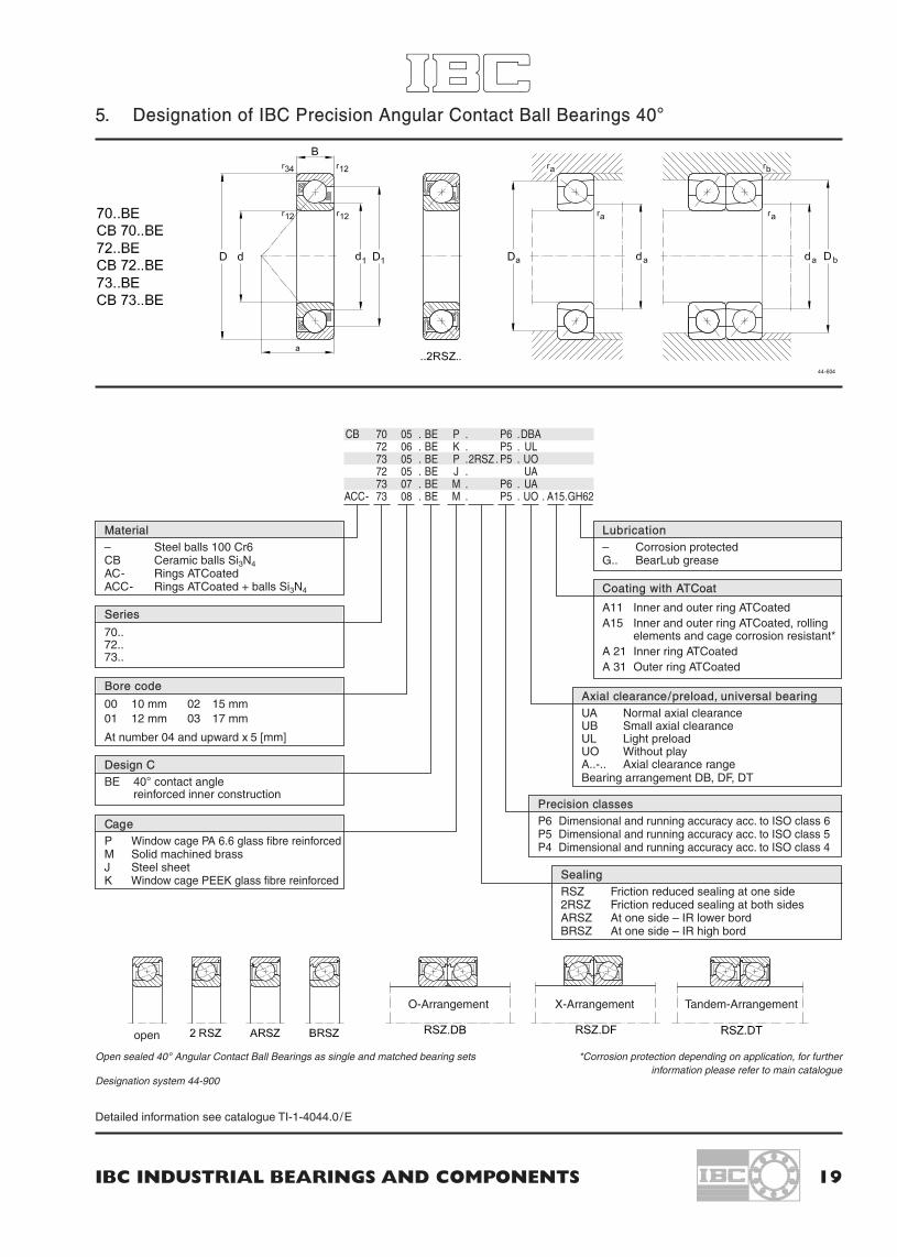
5. Designation of IBC Precision Angular Contact Ball Bearings 40°
CB 70 05 . BE P . P6 .DBA72 06 . BE K . P5 . UL73 05 . BE P .2RSZ . P5 . UO72 05 . BE J . UA73 07 . BE M . P6 . UA
ACC- 73 08 . BE M . P5 . UO . A15.GH62
Material– Steel balls 100 Cr6CB Ceramic balls Si3N4AC- Rings ATCoatedACC- Rings ATCoated + balls Si3N4
Lubrication– Corrosion protectedG.. BearLub grease
Coating with ATCoat
A11 Inner and outer ring ATCoatedA15 Inner and outer ring ATCoated, rolling
elements and cage corrosion resistant*A 21 Inner ring ATCoatedA 31 Outer ring ATCoated
Axial clearance/preload, universal bearingUA Normal axial clearanceUB Small axial clearanceUL Light preloadUO Without playA..-.. Axial clearance rangeBearing arrangement DB, DF, DT
Series
70..72..73..
Design CBE 40° contact angle
reinforced inner construction
CageP Window cage PA 6.6 glass fibre reinforcedM Solid machined brassJ Steel sheetK Window cage PEEK glass fibre reinforced
Precision classesP6 Dimensional and running accuracy acc. to ISO class 6P5 Dimensional and running accuracy acc. to ISO class 5P4 Dimensional and running accuracy acc. to ISO class 4
Open sealed 40° Angular Contact Ball Bearings as single and matched bearing sets
SealingRSZ Friction reduced sealing at one side2RSZ Friction reduced sealing at both sidesARSZ At one side – IR lower bordBRSZ At one side – IR high bord
Detailed information see catalogue TI-1-4044.0/E
Designation system 44-900
Bore code
00 10 mm 02 15 mm01 12 mm 03 17 mm
At number 04 and upward x 5 [mm]
open
O-Arrangement X-Arrangement Tandem-Arrangement
*Corrosion protection depending on application, for furtherinformation please refer to main catalogue

20 IBC WÄLZLAGER GMBH
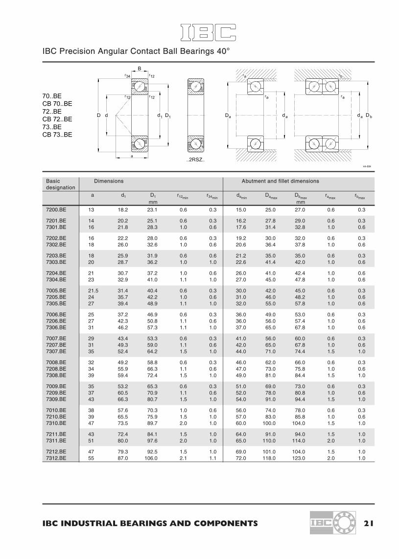
IBC Precision Angular Contact Ball Bearings 40°
Primary dimensions Basic designation Basic load ratings Fatigue load Reference speed Weightdyn. stat. limit
d D B C Co Pu (radial) nr
mm N N min–1 kg
10 30 9 7200.BE 7 700 3 700 140 30 200 0.030
12 32 10 7201.BE 8 300 4 100 160 28 000 0.03612 37 12 7301.BE 12 900 6 500 210 25 900 0.060
15 35 11 7202.BE 9 600 5 100 205 25 900 0.04515 42 13 7302.BE 16 600 9 600 280 21 600 0.083
17 40 12 7203.BE 11 800 6 500 250 21 600 0.06517 47 14 7303.BE 19 000 10 900 360 19 400 0.110
20 47 14 7204.BE 15 700 8 900 360 18 300 0.11020 52 15 7304.BE 22 200 13 600 430 16 200 0.140
25 47 12 7005.BE 14 800 9 300 385 18 900 0.07425 52 15 7205.BE 17 400 10 900 430 16 200 0.13025 62 17 7305.BE 30 900 19 500 660 14 000 0.230
30 55 13 7006.BE 20 600 13 000 520 15 600 0.11030 62 16 7206.BE 24 200 15 600 660 12 900 0.20030 72 19 7306.BE 37 700 25 200 900 11 800 0.340
35 62 14 7007.BE 27 100 17 500 700 14 200 0.15035 72 17 7207.BE 31 900 21 200 880 11 800 0.28035 80 21 7307.BE 46 000 31 900 1 150 10 800 0.450
40 68 15 7008.BE 32 100 22 000 880 12 400 0.18040 80 18 7208.BE 37 800 26 600 1 100 10 200 0.37040 90 23 7308.BE 57 800 40 500 1 350 9 700 0.630
45 75 16 7009.BE 35 700 24 500 980 11 300 0.23045 85 19 7209.BE 42 000 29 800 1 250 9 700 0.42045 100 25 7309.BE 69 600 50 400 1 750 8 600 0.850
50 80 16 7010.BE 37 000 27 500 1 100 10 200 0.25050 90 20 7210.BE 43 500 33 000 1 350 8 600 0.47050 110 27 7310.BE 81 500 55 500 2 200 7 500 1.100
55 100 21 7211.BE 55 000 41 500 1 650 8 100 0.62055 120 29 7311.BE 91 000 71 000 2 550 7 000 1.400
60 110 22 7212.BE 66 000 51 000 2 150 7 300 0.80060 130 31 7312.BE 104 000 82 500 3 200 6 400 1.750
– Bearings with brass cage M have 5% less capacity due to inner construction.– Static capacity Co of hybride bearings CB = 0.7 Co of bearings with steel balls.
IBC INDUSTRIAL BEARINGS AND COMPONENTS 21
IBC Precision Angular Contact Ball Bearings 40°
Basic Dimensions Abutment and fillet dimensionsdesignation
a d1 D1 r12minr34min
daminDamax
Dbmaxramax
rbmaxmm mm
7200.BE 13 18.2 23.1 0.6 0.3 15.0 25.0 27.0 0.6 0.3
7201.BE 14 20.2 25.1 0.6 0.3 16.2 27.8 29.0 0.6 0.37301.BE 16 21.8 28.3 1.0 0.6 17.6 31.4 32.8 1.0 0.6
7202.BE 16 22.2 28.0 0.6 0.3 19.2 30.0 32.0 0.6 0.37302.BE 18 26.0 32.6 1.0 0.6 20.6 36.4 37.8 1.0 0.6
7203.BE 18 25.9 31.9 0.6 0.6 21.2 35.0 35.0 0.6 0.37303.BE 20 28.7 36.2 1.0 1.0 22.6 41.4 42.0 1.0 0.6
7204.BE 21 30.7 37.2 1.0 0.6 26.0 41.0 42.4 1.0 0.67304.BE 23 32.9 41.0 1.1 1.0 27.0 45.0 47.8 1.0 0.6
7005.BE 21.5 31.4 40.4 0.6 0.3 30.0 42.0 45.0 0.6 0.37205.BE 24 35.7 42.2 1.0 0.6 31.0 46.0 48.2 1.0 0.67305.BE 27 39.4 48.9 1.1 1.0 32.0 55.0 57.8 1.0 0.6
7006.BE 25 37.2 46.9 0.6 0.3 36.0 49.0 53.0 0.6 0.37206.BE 27 42.3 50.8 1.1 0.6 36.0 56.0 57.4 1.0 0.67306.BE 31 46.2 57.3 1.1 1.0 37.0 65.0 67.8 1.0 0.6
7007.BE 29 43.4 53.3 0.6 0.3 41.0 56.0 60.0 0.6 0.37207.BE 31 49.3 59.0 1.1 0.6 42.0 65.0 67.8 1.0 0.67307.BE 35 52.4 64.2 1.5 1.0 44.0 71.0 74.4 1.5 1.0
7008.BE 32 49.2 58.8 0.6 0.3 46.0 62.0 66.0 0.6 0.37208.BE 34 55.9 66.3 1.1 0.6 47.0 73.0 75.8 1.0 0.67308.BE 39 59.4 72.4 1.5 1.0 49.0 81.0 84.4 1.5 1.0
7009.BE 35 53.2 65.3 0.6 0.3 51.0 69.0 73.0 0.6 0.37209.BE 37 60.5 70.9 1.1 0.6 52.0 78.0 80.8 1.0 0.67309.BE 43 66.3 80.7 1.5 1.0 54.0 91.0 94.4 1.5 1.0
7010.BE 38 57.6 70.3 1.0 0.6 56.0 74.0 78.0 0.6 0.37210.BE 39 65.5 75.9 1.5 1.0 57.0 83.0 85.8 1.0 0.67310.BE 47 73.5 89.7 2.0 1.0 60.0 100.0 104.0 1.5 1.0
7211.BE 43 72.4 84.1 1.5 1.0 64.0 91.0 94.0 1.5 1.07311.BE 51 80.0 97.6 2.0 1.0 65.0 110.0 114.0 2.0 1.0
7212.BE 47 79.3 92.5 1.5 1.0 69.0 101.0 104.0 1.5 1.07312.BE 55 87.0 106.0 2.1 1.1 72.0 118.0 123.0 2.0 1.0

22 IBC WÄLZLAGER GMBH
IBC Precision Angular Contact Ball Bearings 40°
Primary dimensions Basic designation Basic load ratings Fatigue load Reference speed Weightdyn. stat. limit
d D B C Co Pu (radial) nr
mm N N min–1 kg
65 120 23 7213.BE 74 000 60 500 2 300 6 400 1.00065 140 33 7313.BE 121 000 89 500 3 650 5 900 2.150
70 125 24 7214.BE 80 000 67 500 2 550 5 900 1.10070 150 35 7314.BE 133 500 101 000 3 900 5 400 2.650
75 130 25 7215.BE 82 000 72 000 2 650 5 900 1.20075 160 37 7315.BE 149 000 119 000 4 150 5 400 3.200
80 140 26 7216.BE 92 000 80 000 2 800 5 600 1.40080 170 39 7316.BE 161 000 131 000 4 500 4 800 3.700
85 150 28 7217.BE 103 500 92 000 3 300 5 100 1.80085 180 41 7317.BE 172 500 146 000 4 900 4 800 4.300
90 160 30 7218.BE 122 000 107 000 3 700 4 800 2.20090 190 43 7318.BE 184 000 161 000 5 300 4 300 5.000
95 170 32 7219.BE 133 500 115 000 4 400 4 600 2.600
100 180 34 7220.BE 148 500 131 000 4 400 4 300 3.200100 215 47 7320.BE 222 000 207 000 7 000 3 700 7.200
105 190 36 7221.BE 164 500 148 000 4 800 4 100 4.200
110 200 38 7222.BE 176 000 164 500 4 900 3 700 4.500110 240 50 7322.BE 257 500 257 500 7 200 3 400 9.300
120 215 40 7224.BE 191 000 184 000 5 300 3 400 5.300120 260 55 7324.BE 287 500 299 000 7 700 2 700 12.400
130 230 40 7226.BE 214 000 218 500 6 100 3 200 6.200130 280 58 7326.BE 316 000 345 000 9 000 2 700 15.200
140 250 42 7228.BE 225 500 244 000 6 500 2 700 8.600140 300 62 7328.BE 345 000 391 000 10 000 2 400 20.500
150 270 45 7230.BE 257 500 293 000 7 000 2 400 11.000150 320 65 7330.BE 373 500 448 500 10 500 2 200 25.000
160 290 48 7232.BE 292 000 322 000 8 500 2 300 13.500
170 310 52 7234.BE 334 000 354 000 9 300 2 100 16.000
– Bearings with brass cage M have 5% less capacity due to inner construction.– Static capacity Co of hybride bearings CB = 0.7 Co of bearings with steel balls.

IBC INDUSTRIAL BEARINGS AND COMPONENTS 23
IBC Precision Angular Contact Ball Bearings 40°
Basic Dimensions Abutment and fillet dimensionsdesignation
a d1 D1 r12minr34min
daminDamax
Dbmaxramax
rbmaxmm mm
7213.BE 50 86.3 101.0 1.5 1.0 74.0 111.0 114.0 1.5 1.07313.BE 60 93.8 114.0 2.1 1.1 77.0 128.0 133.0 2.0 1.0
7214.BE 53 91.3 106.0 1.5 1.0 79.0 116.0 119.0 1.5 1.07314.BE 64 100.0 123.0 2.1 1.1 82.0 138.0 143.0 2.0 1.0
7215.BE 56 96.5 111.0 1.5 1.0 84.0 121.0 124.0 1.5 1.07315.BE 68 108.0 130.0 2.1 1.1 87.0 148.0 153.0 2.0 1.0
7216.BE 59 104.0 118.0 2.0 1.0 91.0 129.0 134.0 2.0 1.07316.BE 72 115.0 137.0 2.1 1.1 92.0 158.0 163.0 2.0 1.0
7217.BE 63 110.0 127.0 2.0 1.0 96.0 139.0 144.0 2.0 1.07317.BE 76 122.0 145.0 3.0 1.1 99.0 166.0 173.0 2.5 1.0
7218.BE 67 117.0 135.0 2.0 1.0 101.0 149.0 154.0 2.0 1.07318.BE 80 129.0 153.0 3.0 1.1 104.0 176.0 183.0 2.5 1.0
7219.BE 72 124.0 143.0 2.1 1.1 107.0 158.0 163.0 2.0 1.0
7220.BE 76 131.0 151.0 2.1 1.1 112.0 168.0 173.0 2.0 1.07320.BE 90 145.0 173.0 3.0 1.1 114.0 201.0 208.0 2.5 1.0
7221.BE 80 138.0 159.0 2.1 1.1 117.0 178.0 183.0 2.0 1.0
7222.BE 84 145.0 167.0 2.1 1.1 122.0 188.0 193.0 2.0 1.07322.BE 98 161.0 194.0 3.0 1.1 124.0 226.0 233.0 2.5 1.0
7224.BE 90 157.0 179.0 2.1 1.1 132.0 203.0 208.0 2.0 1.07324.BE 107 178.0 211.0 3.0 1.1 134.0 246.0 253.0 2.5 1.0
7226.BE 96 169.0 193.0 3.0 1.1 144.0 216.0 222.0 2.5 1.07326.BE 115 190.0 228.0 4.0 1.5 147.0 263.0 271.0 3.0 1.5
7228.BE 103 183.0 210.0 3.0 1.1 154.0 236.0 243.0 2.5 1.07328.BE 123 203.0 243.0 4.0 1.5 157.0 283.0 291.0 3.0 1.5
7230.BE 111 197.0 226.0 3.0 1.1 164.0 256.0 263.0 2.5 1.07330.BE 131 216.0 259.0 4.0 1.5 167.0 303.0 311.0 3.0 1.5
7232.BE 118 211.0 242.0 3.0 1.1 174.0 276.0 283.0 2.5 1.0
7234.BE 126 226.0 260.0 3.0 1.1 185.0 297.0 304.0 2.5 1.0

6. Designation of IBC Precision Single Row Deep Groove Ball Bearings
24 IBC WÄLZLAGER GMBH
CB 60 14 . TB . P63 . GH73617 01 . 2RS .Y618 05 . 2Z . . C363 08 . 2Z . . P64
ACC- 60 10 . . TB . P53 . X22 . A15 .GH62
Material– Steel rollers 100 Cr6CB Ceramic rollers Si3N4AC- Rings ATCoatedACC- Rings ATCoated + balls Si3N4
Coating with ATCoatA11 Inner and outer ring ATCoatedA15 Inner and outer ring ATCoated, rolling
elements and cage corrosion resistant*A 21 Inner ring ATCoatedA 31 Outer ring ATCoated
Series
617.. 60..618.. 62..619.. 63..
Grading
X03 Outer diameter in 3 groupsX20 Bore in 2 groupsX22 Outer diameter and bore
in 2 groupsX33 Outer diameter and bore
in 3 groups
Precision classes and radial clearance
P6, P63, P5, P52, P53C2CNC3C4e.g.: P53 = P5 + C3
Sealing
– OpenZ Shield (at one side)2Z Shield (at both sides)RS Seal (at one side)2RS Seal (at both sides)RSZ Seal, low friction, at one side up to Ø 62 mm2RSZ Seal, low friction, at both sides up to Ø 62 mmRSD Seal, low friction, at one side at Ø 62 mm and above2RSD Seal, low friction, at both sides at Ø 62 mm and above
Cage
– Steel sheet cage (standard)TB Fabric reinforced phenolic resin
cage located on inner ringTA Fabric reinforced phenolic resin
cage located on outer ringLB Aluminium cage located on inner
ringLA Aluminium cage located on outer
ringPH Polyamide snap cage
JH Steel sheet snap cageTHB Fabric reinforced phenolic resin
cageMA Solid machined brass, located
on outer ringMB Solid machined brass, located
on inner ringKA PEEK located on outer ringKB PEEK located on inner ringY Brass sheet cage
Designation system 41-900
*Corrosion protection depending on application, for furtherinformation please refer to main catalogue
Lubrication– Corrosion protectedG.. BearLub grease
Bore code
00 10 mm 02 15 mm01 12 mm 03 17 mm
At number 04 and upward x 5 [mm]

IBC INDUSTRIAL BEARINGS AND COMPONENTS 25
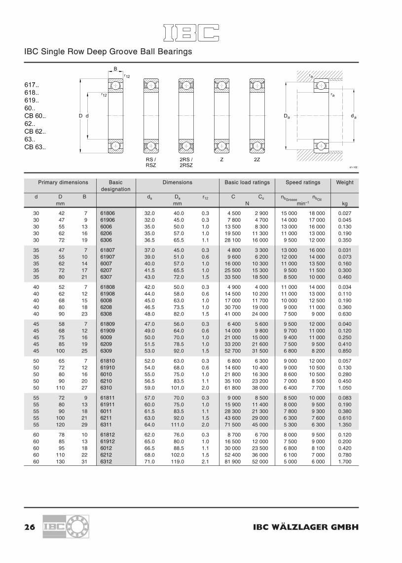
6.1 IBC Single Row Deep Groove Ball Bearings
Primary dimensions Basic Dimensions Basic load ratings Speed ratings Weightdesignation
d D B da Da r12 C Co nbGreasenbOil
mm mm N min–1 kg
10 15 3 61700 11.0 14.0 0.1 870 440 36 000 43 000 0.00210 19 5 61800 12.0 17.0 0.3 1 750 850 37 000 43 000 0.00510 22 6 61900 12.0 20.0 0.3 1 950 750 34 000 41 000 0.01010 26 8 6000 12.0 24.0 0.3 4 600 2 000 31 000 36 500 0.02010 30 9 6200 14.0 26.0 0.6 5 100 2 400 26 000 32 000 0.03210 35 11 6300 14.0 31.0 0.6 8 100 3 500 21 000 27 000 0.055
12 18 4 61701 13.5 17.0 0.2 940 540 31 000 37 000 0.00512 21 5 61801 14.0 19.0 0.3 1 800 950 33 000 39 000 0.00612 24 6 61901 14.0 22.0 0.3 2 900 1 450 31 000 36 000 0.01112 28 8 6001 14.0 26.0 0.3 5 100 2 400 26 500 33 000 0.02212 32 10 6201 16.0 28.0 0.6 6 900 3 100 23 000 29 000 0.03712 37 12 6301 17.0 32.0 1.0 9 700 4 200 19 000 25 000 0.060
15 21 4 61702 16.5 20.0 0.2 960 590 27 000 32 000 0.00615 24 5 61802 17.0 22.0 0.3 2 000 1 250 28 000 33 000 0.00715 28 7 61902 17.0 26.0 0.3 4 100 2 100 26 000 30 000 0.01715 32 9 6002 17.0 30.0 0.3 5 600 2 900 22 500 30 000 0.03015 35 11 6202 19.0 31.0 0.6 7 800 3 800 20 000 24 000 0.04515 42 13 6302 20.0 37.0 1.0 11 400 5 400 17 500 21 000 0.080
17 23 4 61703 18.5 21.5 0.2 1 020 670 25 000 30 000 0.00617 26 5 61803 19.0 24.0 0.3 2 200 1 400 26 000 32 000 0.00917 30 7 61903 19.0 28.0 0.3 4 350 2 350 24 000 28 000 0.01817 35 10 6003 19.0 33.0 0.3 6 100 3 300 20 000 26 000 0.04217 40 12 6203 21.0 36.0 0.6 9 600 4 800 18 000 21 000 0.07017 47 14 6303 22.0 42.0 1.0 13 500 6 600 17 000 20 000 0.120
20 27 4 61704 22.0 25.5 0.2 1 060 740 21 000 25 000 0.00820 32 7 61804 22.0 30.0 0.3 3 450 2 250 20 000 26 000 0.02020 37 9 61904 22.0 35.0 0.3 6 550 3 650 19 000 23 000 0.04020 42 12 6004 24.0 38.0 0.6 9 500 5 200 17 500 21 000 0.07020 47 14 6204 25.0 42.0 1.0 12 800 6 700 15 000 19 000 0.11020 52 15 6304 26.5 45.5 1.1 15 900 7 800 14 000 17 000 0.140
25 32 4 61705 27.0 30.5 0.2 1 110 860 19 000 23 000 0.01025 37 7 61805 27.0 35.0 0.3 4 360 2 600 18 000 25 000 0.02225 42 9 61905 27.0 40.0 0.3 6 650 4 100 16 000 19 000 0.04125 47 12 6005 29.0 43.0 0.6 11 500 6 800 15 500 19 000 0.08025 52 15 6205 30.0 47.0 1.0 14 000 7 900 13 000 16 000 0.13025 62 17 6305 31.5 55.5 1.1 22 500 11 600 12 000 14 000 0.250
IBC Single Row Deep Groove Ball Bearings
26 IBC WÄLZLAGER GMBH
Primary dimensions Basic Dimensions Basic load ratings Speed ratings Weightdesignation
d D B da Da r12 C Co nbGreasenbOil
mm mm N min–1 kg
30 42 7 61806 32.0 40.0 0.3 4 500 2 900 15 000 18 000 0.02730 47 9 61906 32.0 45.0 0.3 7 800 4 700 14 000 17 000 0.04530 55 13 6006 35.0 50.0 1.0 13 500 8 300 13 000 16 000 0.13030 62 16 6206 35.0 57.0 1.0 19 500 11 300 11 000 13 000 0.19030 72 19 6306 36.5 65.5 1.1 28 100 16 000 9 500 12 000 0.350
35 47 7 61807 37.0 45.0 0.3 4 800 3 300 13 000 16 000 0.03135 55 10 61907 39.0 51.0 0.6 9 600 6 200 12 000 14 000 0.07335 62 14 6007 40.0 57.0 1.0 16 000 10 300 11 000 13 500 0.16035 72 17 6207 41.5 65.5 1.0 25 500 15 300 9 500 11 500 0.30035 80 21 6307 43.0 72.0 1.5 33 500 18 500 8 500 10 000 0.460
40 52 7 61808 42.0 50.0 0.3 4 900 4 000 11 000 14 000 0.03440 62 12 61908 44.0 58.0 0.6 14 500 10 200 11 000 13 000 0.11040 68 15 6008 45.0 63.0 1.0 17 000 11 700 10 000 12 500 0.19040 80 18 6208 46.5 73.5 1.0 30 700 19 000 9 000 11 000 0.36040 90 23 6308 48.0 82.0 1.5 41 000 24 000 7 500 9 000 0.630
45 58 7 61809 47.0 56.0 0.3 6 400 5 600 9 500 12 000 0.04045 68 12 61909 49.0 64.0 0.6 14 000 9 800 9 700 11 000 0.12045 75 16 6009 50.0 70.0 1.0 21 000 15 000 9 400 11 000 0.25045 85 19 6209 51.5 78.5 1.0 33 200 21 600 7 500 9 500 0.41045 100 25 6309 53.0 92.0 1.5 52 700 31 500 6 800 8 200 0.850
50 65 7 61810 52.0 63.0 0.3 6 800 6 300 9 000 12 000 0.05750 72 12 61910 54.0 68.0 0.6 14 600 10 400 9 000 10 500 0.13050 80 16 6010 55.0 75.0 1.0 21 800 16 300 8 600 10 500 0.28050 90 20 6210 56.5 83.5 1.1 35 100 23 200 7 000 8 500 0.45050 110 27 6310 59.0 101.0 2.0 61 800 38 000 6 400 7 700 1.050
55 72 9 61811 57.0 70.0 0.3 9 000 8 500 8 500 10 000 0.08355 80 13 61911 60.0 75.0 1.0 15 900 11 400 8 000 9 500 0.19055 90 18 6011 61.5 83.5 1.1 28 300 21 300 7 800 9 300 0.38055 100 21 6211 63.0 92.0 1.5 43 600 29 000 6 300 7 600 0.61055 120 29 6311 64.0 111.0 2.0 71 500 45 000 5 300 6 300 1.350
60 78 10 61812 62.0 76.0 0.3 8 700 6 700 8 000 9 500 0.12060 85 13 61912 65.0 80.0 1.0 16 500 12 000 7 500 9 000 0.20060 95 18 6012 66.5 88.5 1.1 30 000 23 500 6 800 8 100 0.42060 110 22 6212 68.0 102.0 1.5 52 400 36 000 6 100 7 000 0.78060 130 31 6312 71.0 119.0 2.1 81 900 52 000 5 000 6 000 1.700

IBC INDUSTRIAL BEARINGS AND COMPONENTS 27
IBC Single Row Deep Groove Ball Bearings
Primary dimensions Basic Dimensions Basic load ratings Speed ratings Weightdesignation
d D B da Da r12 C Co nbGreasenbOil
mm mm N min–1 kg
65 85 10 61813 69.0 81.0 0.6 12 200 12 000 7 000 8 500 0.13065 90 13 61913 70.0 85.0 1.0 17 400 13 400 6 700 8 000 0.22065 100 18 6013 71.5 93.5 1.1 31 000 25 500 6 400 7 500 0.44065 120 23 6213 73.0 112.0 1.5 55 900 40 500 5 500 6 500 0.99065 140 33 6312 76.0 129.0 2.1 92 300 60 000 4 800 5 600 2.100
70 90 10 61814 74.0 86.0 0.6 12 500 10 000 6 700 8 000 0.16070 100 16 61914 75.0 95.0 1.0 24 000 18 300 6 300 7 500 0.35070 110 20 6014 76.5 103.5 1.1 38 500 31 600 6 100 7 200 0.60070 125 24 6214 78.0 117.0 1.5 67 400 49 300 5 000 6 000 1.10070 150 35 6314 81.0 139.0 2.1 104 000 69 000 4 500 5 400 2.400
75 95 10 61815 79.0 91.0 0.6 12 800 12 100 6 300 7 500 0.16075 105 16 61915 80.0 100.0 1.0 24 200 19 300 6 000 7 000 0.37075 115 20 6015 81.5 108.5 1.1 40 000 33 800 5 700 6 800 0.64075 130 25 6215 83.0 122.0 1.5 66 300 49 000 4 800 5 600 1.20075 160 37 6315 86.0 149.0 2.1 114 000 76 500 4 400 5 100 3.000
80 100 10 61816 84.0 96.0 0.6 12 900 13 700 6 000 7 000 0.17080 110 16 61916 85.0 105.0 1.0 25 100 20 500 5 600 6 700 0.38080 125 22 6016 86.5 118.5 1.1 47 500 40 000 5 300 6 400 0.85080 140 26 6216 89.0 131.0 2.0 72 700 53 000 4 600 5 400 1.40080 170 39 6316 91.0 159.0 2.1 124 000 87 000 3 900 4 600 3.600
85 110 13 61817 90.0 105.0 1.0 19 300 20 000 5 300 6 300 0.29085 120 18 61917 91.5 113.5 1.1 32 000 30 000 5 300 6 300 0.55085 130 22 6017 91.5 123.5 1.1 50 000 43 500 5 100 6 000 0.890
90 115 13 61818 95.0 110.0 1.0 19 600 20 400 5 300 6 300 0.30090 125 18 61918 96.5 118.5 1.1 33 200 31 500 5 000 6 000 0.59090 140 24 6018 98.0 132.0 1.5 59 000 51 000 4 800 5 700 1.150
95 120 16 61819 100.0 115.0 1.0 19 900 17 600 5 000 6 000 0.31095 130 18 61919 101.5 123.5 1.1 35 000 34 000 4 800 5 600 0.61095 145 24 6019 103.0 137.0 1.5 60 600 54 200 4 500 5 400 1.200
100 125 13 61820 105.0 120.0 1.0 19 900 21 200 4 800 5 600 0.310100 140 20 61920 106.5 133.5 1.1 43 000 42 000 4 500 5 300 0.830100 150 24 6020 108.0 142.0 1.5 61 000 54 000 4 300 5 100 1.300
105 130 13 61821 110.0 125.0 1.0 20 800 19 600 4 500 5 300 0.350105 145 20 61921 111.5 138.5 1.1 45 000 44 000 4 300 5 000 0.880105 160 26 6021 114.0 151.0 2.0 73 000 69 000 4 000 4 800 1.600

IBC Single Row Deep Groove Ball Bearings
28 IBC WÄLZLAGER GMBH
41-102
Primary dimensions Basic Dimensions Basic load ratings Speed ratings Weightdesignation
d D B da Da r12 C Co nbGreasenbOil
mm mm N min–1 kg
110 140 16 61822 115.0 135.0 1.0 28 100 29 000 4 300 5 000 0.600110 150 20 61922 116.5 143.5 1.1 44 000 45 000 4 000 4 800 0.900110 170 28 6022 119.0 161.0 2.0 82 000 73 600 3 800 4 600 1.950
120 150 16 61824 125.0 145.0 1.0 29 100 32 500 3 800 4 500 0.650120 165 22 61924 126.5 159.0 1.1 56 000 57 000 3 600 2 040 1.200120 180 28 6024 129.0 171.0 2.0 85 300 80 500 3 600 4 200 2.050
130 165 18 61826 136.5 158.5 1.1 38 000 43 000 3 600 4 300 0.930130 180 24 61926 138.0 172.0 1.5 65 000 67 000 3 400 4 000 1.600130 200 33 6026 139.0 191.0 2.0 108 000 100 000 3 300 3 900 3.150
140 175 18 61828 146.5 168.5 1.1 39 000 46 500 3 400 4 000 1.000140 190 24 61928 148.0 182.0 1.5 67 000 73 000 3 200 3 800 1.900140 210 33 6028 149.0 201.0 2.0 112 000 101 000 3 100 3 600 3.350
150 190 20 61830 156.5 183.5 1.1 48 800 61 000 3 000 3 600 1.040150 210 28 61930 159.0 201.0 2.0 88 500 93 000 2 800 3 400 3.050150 225 35 6030 161.0 214.0 2.1 127 000 126 000 2 600 3 300 4.800
160 200 20 61832 167.0 193.0 1.0 49 500 65 000 2 900 3 500 1.460160 220 28 61932 169.0 211.0 2.0 92 500 99 000 2 600 3 300 3.300160 240 38 6032 171.0 229.0 2.1 145 000 145 000 2 400 3 000 5.900
170 215 22 61834 177.0 208.0 1.0 62 000 79 800 2 600 3 200 1.900170 230 28 61934 179.0 220.0 2.0 94 000 107 000 2 400 3 000 3.500170 260 42 6034 181.0 249.0 2.1 170 000 175 000 2 200 2 800 7.900
180 225 22 61836 187.0 218.0 1.0 62 500 82 000 2 400 3 000 2.000180 250 33 61936 189.0 241.0 2.0 120 000 136 000 2 200 2 800 5.100180 280 46 6036 191.0 269.0 2.1 200 000 205 000 2 100 2 700 10.400
190 240 24 61838 199.0 231.0 1.5 76 000 97 000 2 200 2 800 2.700190 260 33 61938 200.0 250.0 2.0 118 000 135 000 2 100 2 700 5.300190 290 46 6038 201.0 279.0 2.1 208 000 220 000 2 000 2 600 11.000
200 250 24 61840 209.0 242.0 1.5 77 000 104 000 2 100 2 700 2.800200 280 38 61940 212.0 268.0 2.0 150 000 170 000 2 000 2 600 7.400200 310 51 6040 211.0 299.0 2.1 220 000 248 000 1 900 2 400 14.400
220 270 28 61844 220.0 313.0 1.5 79 000 111 000 2 000 2 500 3.000220 300 38 61944 231.0 288.0 2.0 152 000 180 000 1 900 2 400 8.000220 340 56 6044 233.0 327.0 3.0 249 000 297 000 1 800 2 200 18.500

IBC INDUSTRIAL BEARINGS AND COMPONENTS 29
IBC Single Row Deep Groove Ball Bearings
Primary dimensions Basic Dimensions Basic load ratings Speed ratings Weightdesignation
d D B da Da r12 C Co nbGreasenbOil
mm mm N min–1 kg
240 300 28 61848 250.0 292.0 2.0 110 000 150 000 1 900 2 300 4.500240 320 38 61948 252.0 308.0 2.0 160 000 200 000 1 800 2 200 8.500240 360 56 6048 253.0 347.0 3.0 261 000 319 000 1 700 2 000 20.000
260 320 28 61852 270.0 310.0 2.0 112 000 164 000 1 700 2 000 4.800260 360 46 61952 272.0 348.0 2.0 215 000 272 000 1 600 1 900 14.500260 400 65 6052 276.0 384.0 4.0 295 000 378 000 1 600 1 800 29.500
280 350 33 61856 289.0 341.0 2.0 140 000 200 000 1 600 1 900 7.400280 380 46 61956 292.0 368.0 2.0 220 000 290 000 1 500 1 800 15.000280 420 65 6056 296.0 404.0 4.0 305 000 410 000 1 400 1 700 31.000
300 380 38 61860 312.0 368.0 2.0 175 000 245 000 1 400 1 700 10.500300 420 56 61960 314.0 406.0 2.5 270 000 380 000 1 300 1 600 24.500300 460 74 6060 317.0 444.0 3.0 360 000 500 000 1 200 1 500 44.000
320 400 38 61864 332.0 388.0 2.0 173 000 258 000 1 300 1 600 11.000320 440 56 61964 333.0 426.0 2.5 278 000 400 000 1 200 1 500 26.000320 480 74 6064 337.0 464.0 3.0 372 000 540 000 1 100 1 400 46.000
340 420 38 61868 352.0 408.0 2.0 178 000 275 000 1 200 1 500 11.500340 460 56 61968 354.0 446.0 2.5 282 000 425 000 1 100 1 400 27.000
360 440 38 61872 371.0 429.0 2.0 182 000 286 000 1 200 1 500 12.000360 480 56 61972 373.0 466.0 2.5 292 000 450 000 1 100 1 400 28.000
380 480 48 61876 392.0 489.0 2.0 242 000 390 000 1 100 1 400 20.000380 520 65 61976 396.0 503.0 3.0 340 000 540 000 1 000 1 300 40.000
400 500 46 61880 412.0 488.0 2.0 250 000 410 000 1 100 1 300 15.500400 540 65 61980 416.0 524.0 3.0 350 000 570 000 1 000 1 200 41.500
420 520 46 61884 431.0 509.0 2.0 252 000 425 000 975 1 200 22.000420 560 65 61984 436.0 544.0 3.0 352 000 600 000 950 1 100 43.000
440 540 46 61888 451.0 529.0 2.0 255 000 440 000 950 1 100 22.000440 600 74 61988 457.0 583.0 3.0 410 000 720 000 900 1 100 61.000
460 580 56 61892 473.0 567.0 2.5 320 000 570 000 925 1 100 35.000460 620 74 61992 477.0 603.0 3.0 425 000 750 000 875 1 000 62.500
480 600 58 61896 494.0 586.0 2.5 325 000 600 000 875 1 000 37.000480 650 78 61996 500.0 630.0 4.0 450 000 815 000 850 975 74.000
500 620 56 618/500 514.0 606.0 2.5 335 000 620 000 825 975 37.500500 670 78 619/500 520.0 650.0 4.0 465 000 870 000 800 925 77.000
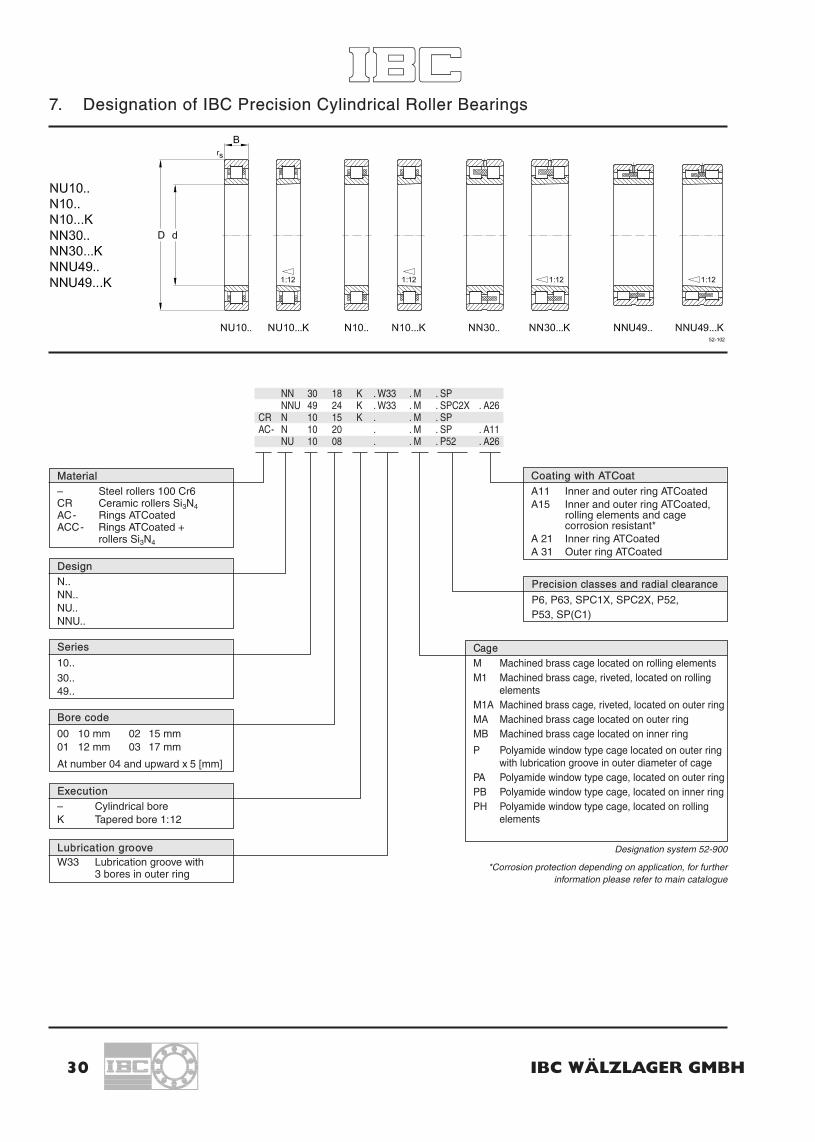
7. Designation of IBC Precision Cylindrical Roller Bearings
30 IBC WÄLZLAGER GMBH
NN 30 18 K . W33 . M . SPNNU 49 24 K . W33 . M . SPC2X . A26
CR N 10 15 K . . M . SPAC- N 10 20 . . M . SP . A11
NU 10 08 . . M . P52 . A26
Material– Steel rollers 100 Cr6CR Ceramic rollers Si3N4AC- Rings ATCoatedACC- Rings ATCoated +
rollers Si3N4
Precision classes and radial clearance
P6, P63, SPC1X, SPC2X, P52,P53, SP(C1)
DesignN..NN..NU..NNU..
Execution– Cylindrical boreK Tapered bore 1:12
CageM Machined brass cage located on rolling elementsM1 Machined brass cage, riveted, located on rolling
elementsM1A Machined brass cage, riveted, located on outer ringMA Machined brass cage located on outer ringMB Machined brass cage located on inner ring
P Polyamide window type cage located on outer ringwith lubrication groove in outer diameter of cage
PA Polyamide window type cage, located on outer ringPB Polyamide window type cage, located on inner ringPH Polyamide window type cage, located on rolling
elements
Series
10..30..49..
Lubrication grooveW33 Lubrication groove with
3 bores in outer ring
Designation system 52-900
*Corrosion protection depending on application, for furtherinformation please refer to main catalogue
Bore code
00 10 mm 02 15 mm01 12 mm 03 17 mm
At number 04 and upward x 5 [mm]
Coating with ATCoat
A11 Inner and outer ring ATCoatedA15 Inner and outer ring ATCoated,
rolling elements and cagecorrosion resistant*
A 21 Inner ring ATCoatedA 31 Outer ring ATCoated

IBC INDUSTRIAL BEARINGS AND COMPONENTS 31
7.1 Production Range IBC Precision Cylindrical Roller Bearings
Production series
NU 10... / NU 10...K N 10... / N 10...K NN 30... / NN 30...K NNU 49... / NNU 49...K
d D B D B D B D Bmm mm mm mm mm
101215172025 NU 1005 47 1230 NU 1006 55 1335 NU 1007 62 1440 NU 1008 68 15 N 1008 68 1545 NU 1009 75 16 N 1009 75 1650 NU 1010 80 16 N 1010 80 16 NN 3010 80 2355 N 1011 90 18 NN 3011 90 2660 N 1012 95 18 NN 3012 95 2665 N 1013 100 18 NN 3013 100 2670 N 1014 110 20 NN 3014 110 3075 N 1015 115 20 NN 3015 115 3080 N 1016 125 22 NN 3016 125 3485 N 1017 130 22 NN 3017 130 3490 N 1018 140 24 NN 3018 140 3795 N 1019 145 24 NN 3019 145 37
100 N 1020 150 24 NN 3020 150 37 NNU 4920 140 40105 N 1021 160 26 NN 3021 160 41 NNU 4921 145 40110 N 1022 170 28 NN 3022 170 45 NNU 4922 150 40120 NN 3024 180 46 NNU 4924 165 45130 NN 3026 200 52 NNU 4926 180 50140 NN 3028 210 53 NNU 4928 190 50150 NN 3030 225 56 NNU 4930 210 60160 NN 3032 240 60 NNU 4932 220 60170 NN 3034 260 67 NNU 4934 230 60180 NN 3036 280 74 NNU 4936 250 69190 NN 3038 290 75 NNU 4938 260 69200 NN 3040 310 82 NNU 4940 280 80220 NNU 4944 300 80240 NNU 4948 320 80260280
Table: Production Range IBC Precision Cylindrical Roller Bearings 14-303

7.2 IBC Precision Cylindrical Roller Bearings
32 IBC WÄLZLAGER GMBH
Primary dimensions Basic Basic load ratings Speed ratings Weightdesignation
d D B C Co nbGreasenbOil
mm N min–1 kg
25 47 12 NU1005 14 200 13 200 15 000 18 000 0.125 52 15 NU205.E 29 000 27 000 11 000 15 000 0.125 52 15 N205.E 29 000 27 000 11 000 15 000 0.1
30 55 13 NU1006 17 900 17 300 12 000 15 000 0.130 62 16 NU206.E 38 000 36 500 10 000 13 000 0.230 62 16 N206.E 38 000 36 500 10 000 13 000 0.2
35 62 20 NN3007K 40 000 52 000 14 000 16 000 0.335 62 14 NU1007 35 800 38 000 10 000 13 000 0.235 72 17 NU207.E 49 000 48 000 9 000 11 000 0.335 72 17 N207.E 49 000 48 000 9 000 11 000 0.3
40 68 15 N1008.K 27 000 31 000 15 000 17 000 0.240 68 21 NN3008K 43 000 57 000 12 000 14 000 0.340 68 15 NU1008 27 000 31 000 9 500 12 000 0.240 80 18 NU208.E 54 000 53 000 8 000 9 000 0.440 80 18 N208.E 54 000 53 000 8 000 9 000 0.4
45 75 16 N1009.K 31 000 34 000 14 000 16 000 0.245 75 23 NN3009K 50 000 67 000 11 000 13 000 0.445 75 16 NU1009 31 000 34 000 9 000 10 000 0.245 85 19 NU209.E 61 000 64 000 7 000 8 000 0.445 85 19 N209.E 61 000 64 000 7 000 8 000 0.4
50 80 16 N1010.K 35 000 40 000 13 000 15 000 0.350 80 23 NN3010K 54 000 74 000 10 000 12 000 0.450 80 16 NU1010 35 000 40 000 8 000 9 500 0.350 90 20 NU210.E 64 000 70 000 6 500 7 500 0.550 90 20 N210.E 64 000 70 000 6 500 7 500 0.5
55 90 18 N1011.K 41 000 50 000 12 000 14 000 0.455 90 26 NN3011K 70 000 98 000 9 500 11 000 0.655 90 18 NU1011 51 000 50 000 7 000 9 000 0.455 100 21 NU211.E 85 000 95 000 6 000 7 000 0.755 100 21 N211.E 85 000 95 000 6 000 7 000 0.7
60 95 18 N1012.K 44 000 55 000 13 000 13 000 0.460 95 26 NN3012K 74 000 110 000 9 000 10 000 0.760 95 18 NU1012 44 000 55 000 7 000 8 500 0.460 110 22 NU212.E 93 500 105 000 5 300 6 300 0.860 110 22 N212.E 93 500 105 000 5 300 6 300 0.8
65 100 20 N1013.K 45 000 58 000 11 000 12 000 0.465 100 26 NN3013K 77 000 116 000 8 500 9 500 0.7

IBC INDUSTRIAL BEARINGS AND COMPONENTS 33
IBC Precision Cylindrical Roller Bearings
Basic Dimensions Abutment and fillet dimensionsdesignation
E F b k r12 r34 s* damindamax
dbminDamax
Daminramax
mm mm
NU1005 0.6 2.0 27.0 43.0 29.0 0.6NU205E 31.5 1.0 0.6 1.3 29.0 30.0 33.0 47.0 1.0N205E 46.5 1.0 0.6 1.3 30.0 45.0 48.0 48.0 1.0
NU1006 1.0 2.0 34.0 50.0 35.0 1.0NU206E 37.5 1.0 0.6 1.3 34.0 36.0 39.0 57.0 1.0N206E 55.5 1.0 0.6 1.3 35.0 54.0 58.0 57.0 1.0
NN3007K 55.0 1.0 1.8 40.0 57.0 56.0 1.0NU1007 1.0 1.0 39.0 57.0 41.0 1.0NU207E 44.0 1.1 0.6 1.3 39.0 42.0 46.0 65.5 1.1N207E 64.0 1.1 0.6 1.3 41.5 62.0 68.0 66.0 1.1
N1008.K 61.0 1.0 0.5 45.0 59.0 63.0 62.0 1.0NN3008K 61.0 1.0 1.3 45.0 63.0 62.0 1.0NU1008 1.0 0.6 2.4 44.0 63.0 49.0 63.0 1.0NU208E 49.5 1.1 1.1 1.4 46.5 48.0 51.0 73.5 1.1N208E 71.5 1.1 1.1 1.4 46.5 69.0 73.5 73.0 1.1
N1009.K 67.5 1.0 0.5 50.0 65.0 70.0 69.0 1.0NN309K 67.5 1.0 2.0 50.0 70.0 69.0 1.0NU1009 1.0 0.6 0.9 49.0 70.0 54.0 70.0 1.0NU209E 54.5 1.1 1.1 1.2 51.5 53.0 56.0 78.5 1.1N209E 76.5 1.1 1.1 1.2 51.5 74.0 78.5 78.0 1.1
N1010.K 72.5 1.0 0.5 55.0 70.0 75.0 74.0 1.0NN3010K 72.5 3.7 2.0 1.0 2.0 55.0 75.0 74.0 1.0NU1010 1.0 0.6 2.5 54.0 75.0 60.0 75.0 1.0NU210E 59.5 1.1 1.1 1.5 56.5 57.0 62.0 83.5 1.1N210E 81.5 1.1 1.1 1.5 56.5 79.0 83.5 84.0 1.1
N1011.K 81.0 1.1 0.6 61.5 79.0 83.5 82.0 1.1NN3011K 81.0 3.7 2.0 1.1 2.0 61.5 83.5 82.0 1.0NU1011 1.1 1.0 0.5 60.0 83.5 67.0 83.5 1.0NU211E 66.0 1.5 1.1 1.0 61.5 64.0 68.0 92.0 1.5N211E 90.0 1.5 1.1 1.0 63.0 88.0 93.5 92.0 1.5
N1012.K 86.1 1.1 0.6 66.5 84.0 88.5 87.0 1.1NN3012K 86.1 3.7 2.0 1.1 2.0 66.5 88.5 87.0 1.0NU1012 1.1 1.0 2.9 65.0 88.5 72.0 88.5 1.0NU212E 72.0 1.5 1.5 1.4 68.0 70.0 74.0 102.0 1.5N212E 100.0 1.5 1.5 1.4 68.0 98.0 102.0 102.0 1.5
N1013.K 91.0 1.1 0.6 71.5 89.0 93.5 92.0 1.1NN3013K 91.0 3.7 2.0 1.1 2.0 71.5 93.5 92.0 1.0
* permissable axial displacement from normal position of one bearing ring to the other.

34 IBC WÄLZLAGER GMBH
IBC Precision Cylindrical Roller Bearings
Primary dimensions Basic Basic load ratings Speed ratings Weightdesignation
d D B C Co nbGreasenbOil
mm N min–1 kg
65 100 18 NU1013 45 000 58 000 6 300 7 500 0.465 120 23 NU213.E 106 000 120 000 4 800 5 600 1.165 120 23 N213.E 106 000 120 000 4 800 5 600 1.1
70 110 20 N1014.K 63 000 78 000 1 000 11 000 0.670 110 30 NN3014K 87 000 148 000 7 500 8 500 1.070 110 20 NU1014 63 000 78 000 5 600 6 800 0.670 125 24 NU214.E 120 000 136 000 4 600 5 400 1.270 125 24 N214.E 120 000 136 000 4 600 5 400 1.2
75 115 22 N1015.K 64 000 80 000 9 000 10 000 0.775 115 30 NN3015K 97 000 153 000 7 000 8 000 1.175 115 20 NU1015 64 000 80 000 5 300 6 300 0.775 130 25 NU215.E 130 000 157 000 4 500 5 300 1.375 130 25 N215.E 130 000 157 000 4 500 5 300 1.3
80 125 22 N1016.K 77 000 95 000 8 500 9 000 0.980 125 34 NN3016K 120 000 184 000 6 700 7 500 1.580 125 22 NU1016 77 000 95 000 5 000 6 000 0.9
85 130 24 N1017.K 75 000 100 000 8 000 8 500 0.985 130 34 NN3017K 125 000 200 000 6 300 7 000 1.685 130 22 NU1017 75 000 100 000 4 800 5 600 0.9
90 140 24 N1018.K 85 000 110 000 7 500 8 000 1.290 140 37 NN3018K 140 000 214 000 6 000 6 700 2.090 140 24 NU1018 95 000 110 000 4 500 5 400 1.2
95 145 24 N1019.K 90 000 120 000 7 000 7 800 1.395 145 37 NN3019K 143 000 230 000 5 600 6 300 2.195 145 24 NU1019 90 000 120 000 4 200 5 000 1.3
100 140 40 NNU4920K 129 000 255 000 5 600 6 300 1.9100 150 24 N1020.K 95 000 130 000 6 700 7 500 1.3100 150 37 NN3020K 152 000 250 000 5 300 6 000 2.2100 150 24 NU1020 95 000 130 000 4 000 4 800 1.3
105 145 40 NNU4921K 130 000 260 000 5 300 6 100 2.0105 160 26 N1021.K 112 000 153 000 6 300 7 000 1.7105 160 41 NN3021K 192 000 310 000 5 000 5 600 2.8105 160 26 NU1021 112 000 153 000 3 800 4 500 1.7
110 150 40 NNU4922K 132 000 270 000 5 100 6 000 2.0110 170 28 N1022.K 130 000 180 000 5 600 6 500 2.0110 170 45 NN3022K 226 000 365 000 4 800 5 300 3.6110 170 28 NU1022 130 000 180 000 3 600 4 300 2.1
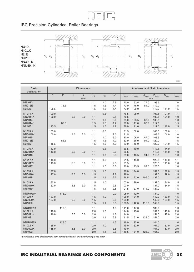
IBC INDUSTRIAL BEARINGS AND COMPONENTS 35
IBC Precision Cylindrical Roller Bearings
Basic Dimensions Abutment and fillet dimensionsdesignation
E F b k r12 r34 s* damindamax
dbminDamax
Daminramax
mm mm
NU1013 1.1 1.0 2.9 70.0 93.5 77.0 93.5 1.0NU213E 78.5 1.5 1.5 1.4 73.0 76.0 81.0 112.0 1.5N213E 108.5 1.5 1.5 1.4 73.0 106.0 112.0 111.0 1.5
N1014.K 100.0 1.1 0.6 76.5 98.0 103.5 101.0 1.1NN3014K 100.0 5.5 3.0 1.1 2.5 76.5 103.5 101.0 1.0NU1014 1.1 1.0 3.0 75.0 103.5 82.0 103.5 1.0NU2014E 83.5 1.5 1.5 1.2 78.0 111.0 86.0 117.0 1.5N214E 113.5 1.5 1.5 1.2 78.0 111.0 117.0 116.0 1.5
N1015.K 105.0 1.1 0.6 81.5 102.0 108.5 106.0 1.1NN3015K 105.0 5.5 3.0 1.1 2.5 81.5 108.5 106.0 1.0NU1015 1.1 1.0 3.0 80.0 108.5 87.0 108.5 1.0NU215E 88.5 1.5 1.5 1.2 83.0 86.0 91.0 122.0 1.5N215E 118.5 1.5 1.5 1.2 83.0 116.0 122.0 121.0 1.5
N1016.K 113.0 1.1 0.6 86.5 110.0 118.5 114.0 1.1NN3016K 113.0 5.5 3.0 1.1 3.0 86.5 118.5 114.0 1.0NU1016 1.1 1.0 3.3 85.0 118.5 94.0 118.5 1.0
N1017.K 118.0 1.1 0.6 91.5 115.0 123.5 119.0 1.1NN3017K 118.0 5.5 3.0 1.1 2.5 91.5 123.5 119.0 1.0NU1017 1.1 1.0 3.3 90.0 123.5 99.0 123.5 1.0
N1018.K 127.0 1.5 1.0 98.0 124.0 132.0 129.0 1.5NN3018K 127.0 5.5 3.0 1.5 2.8 98.0 132.0 129.0 1.5NU1018 1.5 1.1 3.5 96.5 132.0 106.0 132.0 1.5
N1019.K 132.0 1.5 1.0 103.0 129.0 137.0 134.0 1.5NN3019K 132.0 5.5 3.0 1.5 2.8 103.0 137.0 134.0 1.5NU1019 1.5 1.1 3.5 101.5 137.0 111.0 137.0 1.5
NNU4920K 113.0 1.1 2.0 106.0 112.0 134.0 1.0N1020.K 137.0 1.5 1.0 108.0 134.0 142.0 139.0 1.5NN3020K 137.0 5.5 3.0 1.5 2.8 108.0 142.0 139.0 1.5NU1020 1.5 1.1 3.5 106.5 142.0 116.0 142.0 1.5
NNU4921K 118.0 1.1 1.5 111.0 117.0 139.0 1.0N1021.K 146.0 2.0 1.0 114.0 143.0 151.0 148.0 2.0NN3021K 146.0 5.5 3.0 2.0 1.8 114.0 151.0 148.0 2.0NU1021 2.0 1.1 3.8 111.5 151.0 122.0 151.0 2.0
NNU4922K 123.0 1.1 1.5 116.0 122.0 144.0 1.0N1022.K 155.0 2.0 1.0 119.0 152.0 161.0 157.0 2.0NN3022K 155.0 5.5 3.0 2.0 3.8 119.0 161.0 157.0 2.0NU1022 2.0 1.1 3.8 116.5 161.0 128.0 161.0 2.0
* permissable axial displacement from normal position of one bearing ring to the other.

36 IBC WÄLZLAGER GMBH
IBC Precision Cylindrical Roller Bearings
Primary dimensions Basic Basic load ratings Speed ratings Weightdesignation
d D B C Co nbGreasenbOil
mm N min–1 kg
120 165 45 NNU4924K 177 000 342 000 4 800 5 400 2.8120 180 28 N1024.K 140 000 200 000 5 300 6 000 2.2120 180 46 NN3024K 235 000 405 000 4 500 5 000 3.9120 180 28 NU1024 140 000 200 000 3 400 4 000 2.2
130 180 50 NNU4926K 190 000 395 000 4 400 4 800 3.8130 200 33 N1026.K 170 000 245 000 4 800 5 400 3.3130 200 52 NN3026K 294 000 510 000 4 000 4 500 3.8130 200 33 NU1026 170 000 245 000 3 000 3 600 3.3
140 190 50 NNU4928K 192 000 400 000 4 100 4 500 4.1140 210 53 NN3028K 305 000 520 000 3 800 4 300 6.2140 210 33 NU1028 180 000 260 000 3 100 3 500 4.0
150 210 60 NNU4930K 330 000 650 000 3 800 4 300 6.2150 225 56 NN3030K 339 000 600 000 3 600 4 000 7.5150 225 35 NU1030 200 000 310 000 2 700 3 300 4.9
160 220 60 NNU4932K 338 000 680 000 3 600 4 000 6.5160 240 60 NN3032K 370 000 660 000 3 400 3 800 9.1160 240 38 NU1032 240 000 340 000 2 500 3 100 6.0
170 230 60 NNU4934K 340 000 700 000 3 400 3 800 6.9170 260 67 NN3034K 460 000 820 000 3 000 3 400 12.5170 260 42 NU1034 280 000 420 000 2 300 2 800 7.9
180 250 69 NNU4936K 405 000 850 000 3 100 3 500 10.2180 280 74 NN3036K 576 000 1 080 000 2 800 3 200 16.5180 280 46 NU1036 340 000 500 000 2 100 2 600 10.4
190 260 69 NNU4938K 415 000 880 000 2 900 3 300 10.6190 290 75 NN3038K 610 000 1 150 000 2 600 3 000 17.0190 290 46 NU1038 365 000 540 000 2 000 2 500 10.0
200 280 80 NNU4940K 490 000 1 050 000 2 600 3 000 14.9200 310 82 NN3040K 645 000 1 200 000 2 400 2 800 22.0200 310 51 NU1040 400 000 600 000 1 900 2 400 14.0
220 300 80 NNU4944K 520 000 1 150 000 2 400 2 800 16.2220 340 90 NN3044K 810 000 1 500 000 2 200 2 600 28.5220 340 56 NU1044 500 000 750 000 1 800 2 200 18.5
240 320 80 NNU4948K 530 000 1 200 000 2 300 2 600 17.4240 360 92 NN3048K 842 000 1 600 000 2 000 2 400 32.0240 360 56 NU1048 530 000 840 000 1 700 2 000 20.0

IBC INDUSTRIAL BEARINGS AND COMPONENTS 37
IBC Precision Cylindrical Roller Bearings
Basic Dimensions Abutment and fillet dimensionsdesignation
E F b k r12 r34 s* damindamax
dbminDamax
Daminramax
mm mm
NNU4924K 134.5 1.1 1.5 126.0 133.0 159.0 1.0N1024.K 165.0 2.0 1.0 129.0 162.0 171.0 167.0 2.0NN3024K 165.0 5.5 3.0 2.0 3.8 129.0 171.0 167.0 2.0NU1024 2.0 1.1 3.8 126.5 171.0 138.0 171.0 2.0
NNU4926K 146.0 1.5 2.0 137.0 145.0 173.0 1.5N1026.K 182.0 2.0 1.0 139.0 179.0 191.0 183.0 2.0NN3026K 182.0 8.3 4.5 2.0 3.8 139.0 191.0 183.0 2.0NU1026 2.0 1.1 4.7 136.5 191.5 151.0 191.0 2.0
NNU4928K 156.0 1.5 2.0 147.0 155.0 183.0 1.5NN3028K 192.0 8.3 4.5 2.0 3.8 149.0 201.0 194.0 2.0NU1028 2.0 1.1 4.4 146.5 201.0 161.0 201.0 2.0
NNU4930K 168.5 2.0 2.3 159.0 167.0 201.0 2.0NN3030K 206.0 8.3 4.5 2.1 4.0 161.0 214.0 208.0 2.0NU1030 2.1 1.5 4.9 158.0 214.0 173.0 214.0 2.0
NNU4932K 178.5 2.0 2.3 169.0 177.0 211.0 2.0NN3032K 219.0 8.3 4.5 2.1 5.0 171.0 229.0 221.0 2.0NU1032 2.1 1.5 5.2 168.0 229.0 183.0 229.0 2.0
NNU4934K 188.5 2.0 2.3 179.0 187.0 221.0 2.0NN3034K 236.0 8.3 4.5 2.1 5.0 181.0 249.0 238.0 2.0NU1034 193.0 2.1 2.1 5.8 181.0 249.0 196.0 249.0 2.0
NNU4936K 202.0 2.0 2.6 189.0 200.0 241.0 2.0NN3036K 255.0 11.1 6.0 2.1 5.0 191.0 169.0 257.0 2.0NU1036 205.0 2.1 2.1 6.1 191.0 269.0 208.0 269.0 2.0
NNU4938K 212.0 2.0 2.6 199.0 210.0 251.0 2.0NN3038K 265.0 11.1 6.0 2.1 5.0 201.0 279.0 267.0 2.0NU1038 215.0 2.1 2.1 6.1 201.0 279.0 218.0 279.0 2.0
NNU4940K 225.0 2.1 3.4 210.0 223.0 270.0 2.1NN3040K 282.0 11.1 6.0 2.1 6.5 211.0 299.0 285.0 2.0NU1040 229.0 2.1 2.1 7.0 211.0 299.0 233.0 299.0 2.0
NNU4944K 245.0 2.1 3.4 230.0 243.0 290.0 2.1NN3044K 310.0 13.9 7.5 3.0 7.4 233.0 327.0 313.0 2.5NU1044 250.0 3.0 3.0 7.5 233.0 327.0 254.0 327.0 2.5
NNU4948K 265.0 2.1 4.0 250.0 263.0 310.0 2.1NN3048K 330.0 13.9 7.5 3.0 7.4 253.0 347.0 333.0 2.5NU1048 270.0 3.0 3.0 7.5 253.0 347.0 274.0 34.0 2.5
* permissable axial displacement from normal position of one bearing ring to the other.

38 IBC WÄLZLAGER GMBH
IBC Precision Cylindrical Roller Bearings
Primary dimensions Basic Basic load ratings Speed ratings Weightdesignation
d D B C Co nbGreasenbOil
mm N min–1 kg
260 360 100 NNU4952K 750 000 1 700 000 2 100 2 400 30.2260 400 104 NN3052K 1 050 000 1 950 000 1 900 2 200 46.0260 400 65 NU1052 650 000 1 000 000 1 500 1 800 29.0
280 380 100 NNU4956K 770 000 1 800 000 2 000 2 300 32.2280 420 106 NN3056K 1 100 000 2 100 000 1 800 2 000 49.5280 420 65 NU1056 680 000 1 100 000 1 400 1 700 32.5
300 420 118 NNU4960K 1 050 000 2 400 000 1 900 2 100 50.0300 460 118 NN3060K 1 250 000 2 400 000 1 700 1 900 68.5300 460 74 NU1060 890 000 1 400 000 1 200 1 500 44.0
320 440 118 NNU4964K 108 000 2 600 000 1 800 2 000 53.0320 480 121 NN3064K 1 350 000 2 600 000 1 600 1 800 74.0320 480 74 NU1064 900 000 1 450000 1 150 1 400 48.5
340 460 118 NNU4968K 1 100 000 2 700 000 1 600 1 800 56.0340 520 133 NN3068K 1 650 000 3 200 000 1 400 1 600 97.5340 520 82 NU1068 1 100 000 1 800 000 1 100 1 350 65.0
360 480 118 NNU4972K 1 150 000 2 800 000 1 500 1 700 58.5360 540 134 NN3072K 1 750 000 3 500 000 1 400 1 600 105.0360 540 82 NU1072 1 150 000 1 850 000 1 050 1 300 67.5
380 520 140 NNU4976K 1 450 000 3 700 000 1 300 1 600 87.5380 560 135 NN3076K 1 700 000 3 500 000 1 300 1 500 110.0380 560 82 NU1076 1 200 000 2 000 000 1 000 1 200 71.0
400 540 140 NNU4980K 1 500 000 3 800 000 1 300 1 500 91.5400 600 148 NN3080K 2 100 000 4 500 000 1 100 1 300 149.0400 600 90 NU1080 1 380 000 2 320 000 950 1 150 92.5
420 560 140 NNU4984K 1 550 000 4 000 000 1 200 1 400 95.0420 620 150 NN3084K 2 150 000 4 500 000 1 000 1 200 156.0420 620 90 NU1084 1 400 000 2 450 000 900 1 100 96.0
440 600 160 NNU4988K 2 000 000 5 200 000 1 000 1 200 131.0440 650 157 NN3088K 2 500 000 5 100 000 950 1 150 170.0
460 620 160 NNU4992K 2 150 000 5 500 000 1 000 1 200 137.0460 680 163 NN3092K 2 600 000 5 400 000 950 1 150 204.0
480 650 163 NNU4996K 2 400 000 6 100 000 1 000 1 200 162.0480 700 165 NN3096K 2 700 000 5 900 000 950 1 100 214.0

IBC INDUSTRIAL BEARINGS AND COMPONENTS 39
IBC Precision Cylindrical Roller Bearings
Basic Dimensions Abutment and fillet dimensionsdesignation
E F b k r12 r34 s* damindamax
dbminDamax
Daminramax
mm mm
NNU4952K 292.0 2.1 4.0 270.0 289.0 350.0 2.1NN3052K 364.0 13.9 7.5 4.0 7.4 276.0 384.0 367.0 3.0NU1052 296.0 4.0 4.0 8.8 276.0 384.0 300.0 384.0 3.0
NNU4956K 312.0 2.1 5.0 290.0 309.0 370.0 2.1NN3056K 384.0 13.9 7.5 4.0 12.4 296.0 404.0 387.0 3.0NU1056 216.0 4.0 4.0 8.8 296.0 404.0 320.0 404.0 3.0
NNU4960K 339.0 3.0 5.0 312.0 335.0 408.0 2.5NN3060K 418.0 16.7 9.0 4.0 8.9 316.0 444.0 421.0 3.0NU1060 340.0 4.0 4.0 9.7 316.0 444.0 344.0 444.0 3.0
NNU4964K 359.0 3.0 5.5 333.0 355.0 427.0 2.5NN3064K 438.0 16.7 9.0 4.0 8.9 336.0 464.0 442.0 3.0NU1064 360.0 4.0 4.0 9.7 336.0 464.0 364.0 464.0 3.0
NNU4968K 379.0 3.0 5.5 353.0 375.0 447.0 2.5NN3068K 473.0 16.7 9.0 5.0 10.9 360.0 500.0 477.0 4.0NU1068 385.0 5.0 5.0 10.8 360.0 500.0 389.0 500.0 4.0
NNU4972 399.0 3.0 5.5 373.0 395.0 467.0 2.5NN3072K 493.0 16.7 9.0 5.0 5.0 10.9 380.0 520.0 497.0 4.0NU1072 405.0 5.0 5.0 10.8 380.0 520.0 410.0 520.0 4.0
NNU4976K 426.0 4.0 5.5 396.0 421.0 504.0 3.0NN3076K 513.0 16.7 9.0 5.0 5.0 11.9 400.0 540.0 518.0 4.0NU1076 425.0 5.0 5.0 10.8 400.0 540.0 430.0 540.0 4.0
NNU4980K 446.0 4.0 5.5 416.0 441.0 524.0 3.0NN3080K 549.0 17.7 9.5 5.0 5.0 12.5 418.0 580.0 553.0 4.0NU1080 450.0 5.0 5.0 14.0 420.0 580.0 455.0 580.0 4.0
NNU4984K 466.0 4.0 5.5 436.0 461.0 544.0 3.0NN3084K 569.0 17.7 9.5 12.0 440.0 600.0 574.0 4.0NU1084 470.0 5.0 5.0 14.0 440.0 600.0 475.0 600.0 4.0
NNU4988K 490.0 4.0 5.5 457.0 483.0 584.0 3.0NN3088K 597.0 22.3 12.0 6.0 6.0 13.0 467.0 624.0 600.0 5.0
NNU4992K 510.0 4.0 5.5 477.0 503.0 604.0 3.0NN3092K 624.0 22.3 12.0 6.0 6.0 13.5 487.0 654.0 627.0 5.0
NNU4996K 534.0 5.0 5.5 497.0 523.0 624.0 4.0NN3096K 644.0 22.3 12.0 6.0 6.0 13.5 505.0 674.0 647.0 5.0
* permissable axial displacement from normal position of one bearing ring to the other.

40 IBC WÄLZLAGER GMBH
8. Designation of IBC Thrust Ball Bearings
ACC 511 14 . JCN . A 15511 07 . 2 GS511 34 . F . P6512 08 . . . P5
AC- 511 10 . . . P6 . A11
Material– Steel rollers 100 Cr6CR Ceramic rollers Si3N4AC- Rings ATCoatedACC- Rings ATCoated +
balls Si3N4
Quality
P6 ISO 6P5 ISO 5P4 ISO 4
Special versions
2 WS Two shaft washers2 GS Two housing washers
Series
511..512..
Bore code
00 10 mm 02 15 mm01 12 mm 03 17 mm
At number 04 and upwards x 5 [mm]
Designation system 43-900
*Corrosion protection depending on application, for furtherinformation please refer to main catalogue
Cage– Pressed steelF Steel massive bonderizedJCN Pressed steel Ni-coatedMP Brass massive
ATCoated thin dense chrome
A11 Washers ATCoatedA15 Washers ATCoated,
rolling elements and cagecorrosion resistant*

IBC INDUSTRIAL BEARINGS AND COMPONENTS 41
8.1 IBC Thrust Ball Bearings
Single direction thrust ball bearings can only accommodateaxial loads, only in one direction and no radial loads. As theyare separable their three parts the shaft washer, the ball andcage assembly and the housing washer can be mounted sep-arately.
DimensionsThe boundary dimensions are according to ISO 104-1979(AFBMA standard 24.1) thrust bearings with flat back facesand DIN 711.
MisaligmentNot permitted.
TolerancesIBC thrust ball bearings are manufactured to normal toler-ances as well as to higher accuracy, P6, P5 due to DIN 620,part 3.
CageThe cages are made out of pressed steel.Special executions (brass) on request.
ExecutionsStandard: rings made of steel or these ATCoated (wear andcorrosion protection)
Minimum loadIn order to assure satisfactory rolling condition despite theinteria forces acting on balls and cage a minimum loadFa min should be applied avoiding skidding of balls:
Fa min = fa min ( )2 [N]
fa min see data table next page 42n [min-1]
Recommended fits of adjacent parts:shaft h6, js6; housing H8.
n1000

42 IBC WÄLZLAGER GMBH
8.2 IBC Thrust Ball Bearings
Primary Basic Dimensions Basic load Load Speed ratings Weightdimensions designation ratings factor ng md D T d1 D1 r12 da Da ramax
C C0 faminGrease Oil
mm mm N min-1 kg
10 24 9 51100 24 11 0.5 19 15 0.3 9 950 14 000 1 7 000 9 500 0.020
12 26 9 51101 26 13 0.5 21 17 0.3 10 400 15 300 0.8 6 700 9 000 0.022
15 28 9 51102 28 16 0.5 23 20 0.3 9 360 14 000 1 6 300 9 500 0.02415 32 12 51202 32 17 1.0 25 22 0.6 16 500 25 000 3 5 300 7 000 0.046
17 30 9 51103 30 18 0.5 25 22 0.3 9 750 15 300 1 6 300 8 500 0.02817 35 12 51203 35 19 1.0 28 24 0.6 17 200 27 500 4 5 000 6 700 0.053
20 35 10 51104 35 21 0.5 29 26 0.3 12 700 20 800 2 5 600 7 500 0.04020 40 14 51204 40 22 1.0 32 28 0.6 22 500 37 500 7 4 500 6 000 0.082
25 42 11 51105 42 26 1.0 35 32 0.6 15 900 29 000 4 4 800 6 300 0.05925 47 15 51205 47 27 1.0 38 34 0.6 27 600 50 000 13 4 000 5 300 0.120
30 47 11 51106 47 32 1.0 40 37 0.6 16 800 33 500 6 4 500 6 000 0.06830 52 16 51206 52 32 1.0 43 39 0.6 25 500 47 500 11 3 600 4 800 0.144
35 52 12 51107 52 37 1.0 45 42 0.6 17 400 37 500 7 4 300 5 600 0.08535 62 18 51207 62 37 1.5 51 46 1.0 35 100 67 000 23 3 000 4 000 0.220
40 60 13 51108 60 42 1.0 52 48 0.6 23 400 50 000 13 3 800 5 000 0.12040 68 19 51208 68 42 1.5 57 51 1.0 46 800 98 000 50 2 800 3 800 0.270
45 65 14 51109 65 47 1.0 57 53 0.6 24 200 57 000 16 3 400 4 500 0.15045 73 20 51209 73 47 1.5 62 56 1.0 39 000 80 000 34 2 600 3 600 0.320
50 70 14 51110 70 52 1.0 62 58 0.6 25 500 63 000 20 3 200 4 300 0.16050 78 22 51210 78 52 1.5 67 61 1.0 49 400 106 000 60 2 400 3 400 0.390
55 78 16 51111 78 57 1.0 69 64 0.6 30 700 78 000 32 2 800 3 800 0.24055 90 25 51211 90 57 1.5 76 69 1.0 61 800 134 000 94 1 900 2 800 0.610
60 85 17 51112 85 62 1.5 75 70 1.0 36 400 93 000 45 2 600 3 600 0.29060 95 26 51212 95 62 1.5 81 74 1.0 62 400 140 000 100 1 900 2 800 0.690
65 90 18 51113 90 67 1.5 80 75 1.0 37 100 98 000 50 2 400 3 400 0.34065 100 27 51213 100 67 1.5 86 79 1.0 63 700 150 000 120 1 800 2 600 0.770
70 95 18 51114 95 72 1.5 85 80 1.0 37 700 104 000 57 2 400 3 400 0.36070 105 27 51214 105 72 1.5 91 84 1.0 65 000 160 000 130 1 800 2 600 0.810

IBC INDUSTRIAL BEARINGS AND COMPONENTS 43
IBC Thrust Ball Bearings
Primary Basic Dimensions Basic load Load Speed ratings Weightdimensions designation ratings factor ng md D T d1 D1 r12 da Da ramax
C C0 faminGrease Oil
mm mm N min-1 kg
75 100 19 51115 100 77 1.5 90 85 1.0 44 200 137 000 100 2 200 3 200 0.42075 110 27 51215 110 77 1.5 96 89 1.0 67 600 170 000 150 1 700 2 400 0.860
80 105 19 51116 105 82 1.5 95 90 1.0 44 900 140 000 100 2 000 3 000 0.43080 115 28 51216 115 82 1.5 101 94 1.0 76 100 190 000 190 1 700 2 400 0.950
85 110 19 51117 110 87 1.5 100 95 1.0 46 200 150 000 122 2 000 3 000 0.46085 125 31 51217 125 88 1.5 109 101 1.0 97 500 250 000 340 1 600 2 200 1.290
90 120 22 51118 120 92 1.5 108 102 1.0 59 200 190 000 190 2 600 1 800 0.68090 135 35 51218 135 93 2.0 117 108 1.0 119 000 300 000 480 2 000 1 500 1.770
100 135 25 51120 135 102 1.5 121 114 1.0 85 200 270 000 390 2 400 1 700 0.990100 150 38 51220 150 103 2.0 130 120 1.0 124 000 320 000 540 1 800 1 300 2.360
110 145 25 51122 145 112 1.5 131 124 1.0 87 100 290 000 445 2 200 1 600 1.080110 160 38 51222 160 113 2.0 140 130 1.0 130 000 360 000 680 1 700 1 200 2.570
120 155 25 51124 155 122 1.5 141 134 1.0 88 400 310 000 500 2 200 1 600 1.160120 170 39 51224 170 123 2.0 150 140 1.0 140 000 400 000 840 1 600 1 100 2.860
130 170 30 51126 170 132 1.5 154 146 1.0 111 000 390 000 800 1 900 1 400 1.870
140 180 31 51128 178 142 1.5 164 156 1.0 111 000 400 000 835 1 800 1 300 2.070
150 190 31 51130 188 152 1.5 174 166 1.0 111 000 400 000 840 1 700 1 200 2.200
160 200 31 51132 198 162 1.5 184 176 1.0 112 000 425 000 950 1 700 1 200 2.330
170 215 34 51134 213 172 2.0 197 188 1.0 133 000 500 000 1350 1 600 1 100 3.310
180 225 34 51136 222 183 2.0 207 198 1.0 135 000 530 000 1500 1 500 1 000 3.480
190 240 37 51138 237 193 2.0 220 210 1.0 172 000 655 000 2250 1 400 950 4.060
200 250 37 51140 247 203 2.0 230 220 1.0 168 000 655 000 2300 1 400 950 4.240

44 IBC WÄLZLAGER GMBH
9. Designation of IBC 60° Super Precision Angular Contact Thrust Ball Bearings
Detailed information see catalogue TI-1-5010.2/E
Material– Steel balls 100 Cr6CB Ceramic balls Si3N4AC- Rings ATCoatedACC- Rings ATCoated +
balls Si3N4
Lubrication– 50 % / GH62 (standard)GN21G 30–35 % / GN21OX Corrosion protected
Arrangement– Single bearingD Duplex set universalT Triplex setQ Quadruple set universalBearing arrangements (sets) see page 7
PrecisionP4A
SeriesBS 60° Ang. Contact Ball Bearings
Bore code25 M Metric bore 25 mm150 l Inch bore 1.50"
Dimension unitM MetricI Inch
Outer diameterOnly metric bearings are marked [mm]
Bearing widthStandard width not marked/17 = 17 mm width according to DIN 616
SealingRSZ Friction reduced sealing at one side2RSZ Friction reduced sealing at both sides
Designation system 54-900
*Corrosion protection depending on application, for furtherinformation please refer to main catalogue
CB BS 75 M 110 S . P4A . D . UM . OXBS 30 M 62 /16 . 2RSZ P4A . UL
AC BS 50 M 100 P4A . Q . UM– BS 25 M 62 /17 P4A . D . UH. A15 . GH62G
Coating with ATCoatA11 Inner and outer ring ATCoatedA15 Inner and outer ring ATCoated, rolling
elements and cage corrosion resistant*A 21 Inner ring ATCoatedA 31 Outer ring ATCoated
Axial clearance/preload, universal bearing
UL LightUM MediumUH HighU.. Special preload in daNA..-.. Axial clearance range
Lubrication groove and boreS Oil lubrication via outer ring
(not all combinations are possible)

IBC INDUSTRIAL BEARINGS AND COMPONENTS 45
More information:See catalogue Ball Screw Support Bearings TI-1-5012.2/E
9.1 60° Super Precision Angular Contact Thrust Ball Bearings
IBC angular contact thrust ball bearings have been devel-oped to meet the demands of high thrust load for ballscrew support application.The large contact angle of 60° allows for high thrust loadwith high stiffness. The radial load should not extend90 % of the preload.As angular contact bearings can carry load only in onedirection they therefore have to be adjusted to anotherbearing of the same kind.The bearings are primarily supplied as single ones or insets of 2 or 4 bearings to be mounted in back-to-backarrangements.Angular contact thrust bearings are manufactured for uni-versal matching, thus they can be rearranged and can bemounted in any arrangement.As a standard single bearings have a medium or high pre-load, sets have a V-marking, single doesn’t.
Precision grades: Bore and O.D. are manufactured toprecision class P4A; axial runout Sd and Sia are restrictedto P2A (see page 48).
Preload60°-Angular contact bearings are available with light,medium and high preload. They are apt for mounting insets. For preloading we recommend the locknuts of seriesMMRB or MMRS (starting page 60). With tight fits the pre-load will be enhanced.
Material of rings and ballsStandard: bearing steel 100Cr6 (1.3505)
Options:CB: ceramic Si3N4 with speed increase of 35 %AC: rings thin dense chromium ATCoated (details to the
option see page 65)
Cage: The one-piece glass fibre, reinforced polyamidecage is ball guided. As standard this is not designated.Temperature range –30 to 120 °C.
Lubrication:The bearings are supplied with approved special greasesas standard:a) For lower and medium speed: with the high viscose
BearLub GH62b) For top speed range: with BearLub GN21. For this
grease the speed limits are given in the data tables onpage 47 and 56. For technical information on greasessee page 74.
(Bearings with oil lubrication holes on request).
SealingMost of the bearings are supplied as open bearings andcan be combined with labyrinth-seals of series S acc. topage 63.The types on page 46 marked with + are also manufac-tured with non-touching seals .2RSZ.
Simply mountingWhereas at the beginning (a) ball screw bearings had tobe built in separately with other parts, now the ready-to-mount units are the state of art. The mounting of completesubassemblies eases and speeds up the mounting. Theavoidance of an axial reference face in the housing boresimplifies surrounding parts (b).
2) Fixed end and floating end combinationsa) see page 57, 58 and front page.b) with spring preload at one side, see page 64
3) Fixed clamping at both endsa) for driven spindle
b) for driven nut (see page 54), e.g. assembled with BNBU63QB130 2.M.M2 with integrated labyrinth seals, n =1000 min-1. Spindle Ø 40 x 10 fixed at ends (also avail-able as BNBUS... with integrated lubricating system forthe nut).
Arrangements1) Fixed clamping at one end

9.2 Super Precision 60° Angular Contact Thrust Ball Bearings metric, inch
46 IBC WÄLZLAGER GMBH
Dimensions Basic designation Abutment and fillet dimensions Basic load ratings Weightd D B r1.2 r34 a ramax
rbmaxdamin
DamaxDbmax
Ca Coa
mm min min � mm N kg
17 47 15 0.6 0.6 36.5 BS17M47 1.0 0.6 26 38 40 25 000 32100 0.13
20 47 14 0.6 0.6 36 BS20M47/14* 1.0 0.6 28 38 40 25 000 32 100 0.1420 47 15 0.6 0.6 36.5 BS20M47 1.0 0.6 28 38 40 25 000 32 100 0.14
25 52 15 1.0 0.6 39 BS25M52 + 1.0 0.6 34 44 45 26 500 37 000 0.2225 62 15 1.0 0.6 46.5 BS25M62 + 1.0 0.6 34 52 54 29 200 42 800 0.2725 62 17 1.0 0.6 47.5 BS25M62/17* + 1.0 0.6 34 52 54 29 200 42 800 0.27
30 62 15 1.0 0.6 46 BS30M62 + 1.0 0.6 38 52 54 29 200 42 800 0.2530 62 16 1.0 0.6 47 BS30M62/16* + 1.0 0.6 38 52 54 29 200 42 800 0.2530 72 15 1.0 0.6 56 BS30M72 + 1.0 0.6 39 63 64 35 600 55 000 0.3230 72 19 1.0 0.6 58 BS30M72/19* + 1.0 0.6 39 63 64 35 600 55 000 0.32
35 72 15 1.0 0.6 56 BS35M72 + 1.0 0.6 43 63 64 35 600 55 000 0.2935 72 17 1.0 0.6 57 BS35M72/17* + 1.0 0.6 43 63 64 35 600 55 000 0.3435 100 20 1.0 0.6 75 BS35M100 + 1.0 0.6 47 86 89 70 500 116 000 1.05
40 72 15 1.0 0.6 56 BS40M72 + 1.0 0.6 48 63 64 35 600 55 000 0.2840 90 20 1.0 0.6 71.5 BS40M90 + 1.0 0.6 49 80 82 59 000 90 000 0.6440 90 23 1.0 0.6 73 BS40M90/23* + 1.0 0.6 49 80 82 59 000 90 000 0.7240 100 20 1.0 0.6 75 BS40M100 + 1.0 0.6 49 86 89 70 500 116 000 1.00
45 75 15 1.0 0.6 60 BS45M75 1.0 0.6 53 65 67 37 900 61 400 0.2945 100 20 1.0 0.6 75 BS45M100 + 1.0 0.6 54 86 89 70 500 116 000 0.95
50 90 20 1.0 0.6 71.5 BS50M90 1.0 0.6 59 80 82 59 000 90 000 0.6050 100 20 1.0 0.6 75 BS50M100 + 1.0 0.6 59 86 89 70 500 116 000 0.89
55 90 15 1.0 0.6 73 BS55M90 + 1.0 0.6 64 78 81 40 700 74 400 0.4255 100 20 1.0 0.6 75 BS55M100 1.0 0.6 65 86 89 70 500 116 000 0.7155 120 20 1.0 0.6 88 BS55M120 1.0 0.6 65 106 108 80 800 137 000 1.43
60 120 20 1.0 0.6 88 BS60M120 1.0 0.6 70 100 108 80 800 137 000 1.36
75 110 15 1.0 0.6 89 BS75M110 1.0 0.6 85 98 100 44 500 93 800 0.48
100 150 22.5 1.0 0.6 118 BS100M150 1.0 0.6 114 135 137 86 400 192 000 1.00
127 180 22.225 1.0 0.6 143 BS127M180 1.0 0.6 140 165 168 85 200 239 300 1.24
20 47 15.875 1.0 0.6 38 BS078 I 1.0 0.6 28 38 40 25 000 32 100 0.1423.838 62 15.875 1.0 0.6 50 BS093 I 1.0 0.6 32 52 54 29 200 42 800 0.2538.100 72 15.875 1.0 0.6 56 BS150 I 1.0 0.6 46 62 64 35 600 55 000 0.2844.475 76.2 15.875 1.0 0.6 60 BS175 I 1.0 0.6 52 66 68 37 900 61 400 0.30
* Should no more be used in new applications. + with seals: suffix .2RSZ
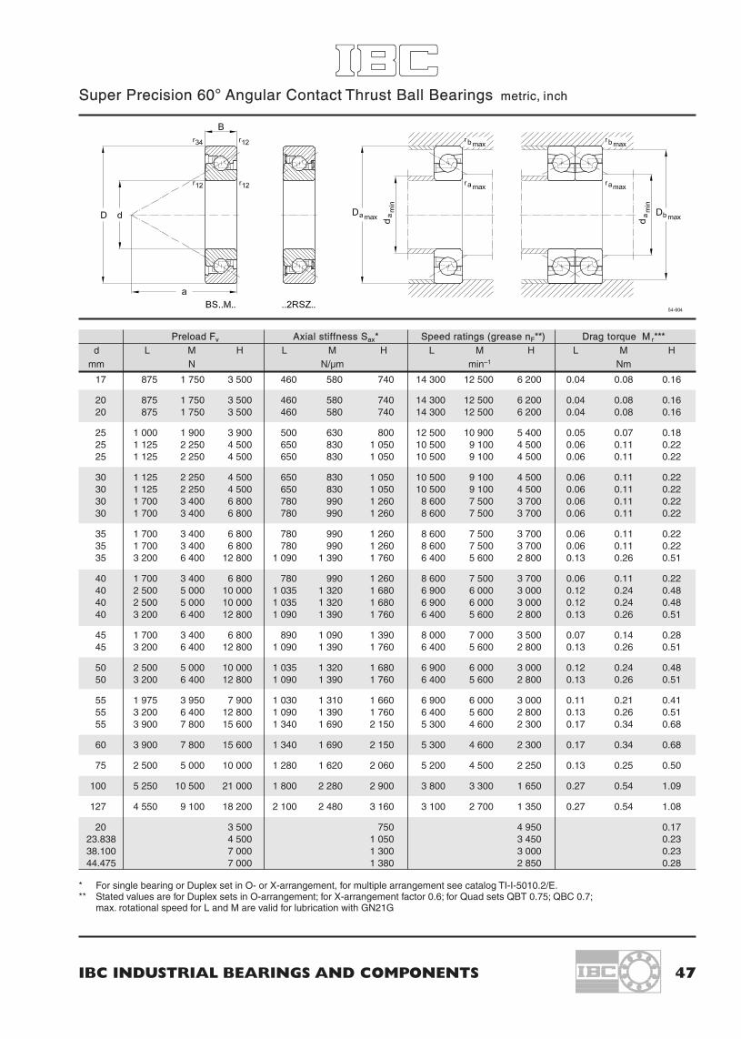
IBC INDUSTRIAL BEARINGS AND COMPONENTS 47
Super Precision 60° Angular Contact Thrust Ball Bearings metric, inch
Preload Fv Axial stiffness Sax* Speed ratings (grease nF**) Drag torque M r***d L M H L M H L M H L M H
mm N N/µm min–1 Nm
17 875 1 750 3 500 460 580 740 14 300 12 500 6 200 0.04 0.08 0.16
20 875 1 750 3 500 460 580 740 14 300 12 500 6 200 0.04 0.08 0.1620 875 1 750 3 500 460 580 740 14 300 12 500 6 200 0.04 0.08 0.16
25 1 000 1 900 3 900 500 630 800 12 500 10 900 5 400 0.05 0.07 0.1825 1 125 2 250 4 500 650 830 1 050 10 500 9 100 4 500 0.06 0.11 0.2225 1 125 2 250 4 500 650 830 1 050 10 500 9 100 4 500 0.06 0.11 0.22
30 1 125 2 250 4 500 650 830 1 050 10 500 9 100 4 500 0.06 0.11 0.2230 1 125 2 250 4 500 650 830 1 050 10 500 9 100 4 500 0.06 0.11 0.2230 1 700 3 400 6 800 780 990 1 260 8 600 7 500 3 700 0.06 0.11 0.2230 1 700 3 400 6 800 780 990 1 260 8 600 7 500 3 700 0.06 0.11 0.22
35 1 700 3 400 6 800 780 990 1 260 8 600 7 500 3 700 0.06 0.11 0.2235 1 700 3 400 6 800 780 990 1 260 8 600 7 500 3 700 0.06 0.11 0.2235 3 200 6 400 12 800 1 090 1 390 1 760 6 400 5 600 2 800 0.13 0.26 0.51
40 1 700 3 400 6 800 780 990 1 260 8 600 7 500 3 700 0.06 0.11 0.2240 2 500 5 000 10 000 1 035 1 320 1 680 6 900 6 000 3 000 0.12 0.24 0.4840 2 500 5 000 10 000 1 035 1 320 1 680 6 900 6 000 3 000 0.12 0.24 0.4840 3 200 6 400 12 800 1 090 1 390 1 760 6 400 5 600 2 800 0.13 0.26 0.51
45 1 700 3 400 6 800 890 1 090 1 390 8 000 7 000 3 500 0.07 0.14 0.2845 3 200 6 400 12 800 1 090 1 390 1 760 6 400 5 600 2 800 0.13 0.26 0.51
50 2 500 5 000 10 000 1 035 1 320 1 680 6 900 6 000 3 000 0.12 0.24 0.4850 3 200 6 400 12 800 1 090 1 390 1 760 6 400 5 600 2 800 0.13 0.26 0.51
55 1 975 3 950 7 900 1 030 1 310 1 660 6 900 6 000 3 000 0.11 0.21 0.4155 3 200 6 400 12 800 1 090 1 390 1 760 6 400 5 600 2 800 0.13 0.26 0.5155 3 900 7 800 15 600 1 340 1 690 2 150 5 300 4 600 2 300 0.17 0.34 0.68
60 3 900 7 800 15 600 1 340 1 690 2 150 5 300 4 600 2 300 0.17 0.34 0.68
75 2 500 5 000 10 000 1 280 1 620 2 060 5 200 4 500 2 250 0.13 0.25 0.50
100 5 250 10 500 21 000 1 800 2 280 2 900 3 800 3 300 1 650 0.27 0.54 1.09
127 4 550 9 100 18 200 2 100 2 480 3 160 3 100 2 700 1 350 0.27 0.54 1.08
20 3 500 750 4 950 0.1723.838 4 500 1 050 3 450 0.2338.100 7 000 1 300 3 000 0.2344.475 7 000 1 380 2 850 0.28
* For single bearing or Duplex set in O- or X-arrangement, for multiple arrangement see catalog TI-I-5010.2/E.** Stated values are for Duplex sets in O-arrangement; for X-arrangement factor 0.6; for Quad sets QBT 0.75; QBC 0.7;
max. rotational speed for L and M are valid for lubrication with GN21G

48 IBC WÄLZLAGER GMBH
9.3 Tolerances of Super Precision 60° Angular Contact Thrust Bearings
9.4 Proposed fits for Super Precision 60° Angular Contact Thrust Bearings
Data table in µm
Inner ring [mm] Precision Ø 0.6 10 18 30 50 80 120to 10 18 30 50 80 120 150
∆dmp Max. deviation of the mean P4A –4 –4 –4 –5 –5 –6 –7.5bore diameter from thenominal
Kia Radial runout of assembled P4A 2.5 2.5 2.5 4 4 5 6bearing inner ring
Sd Side face runout referring to P2A 1.3 1.3 1.3 1.3 1.3 2.5 2.5bore of inner ring
Sia Side face runout with reference P2A 1.3 1.3 2.5 2.5 2.5 2.5 2.5to the raceway of theassembled bearing inner ring
∆Bs Deviation of single inner ring P4A, P2A –200 –200 –200 –200 –250 –320 –370width
VBs Ring width variation P4A 2.5 2.5 2.5 2.5 4 4 5
Outer ring [mm] Precision Ø 18 30 50 80 120 150 180to 30 50 80 120 150 180 250
∆Dmp Max. deviation of mean outside P4A, P2H –5 –5 –5 –7.5 –9 –10 –10diameter to nominal
Kea Radial runout of assembled P4A 4 5 5 5 7 7.5 10bearing outer ring
SD Variation in inclination of P2A 1.3 1.3 1.3 2.5 2.5 2.5 3.8outside cylindrical surfaceto outer ring side face
Sea Side face runout referring to P2A 2.5 2.5 3.8 5 5 5 6.4raceway of assembledbearing outer ring
The width tolerances of the outer ring (∆Cs, Vcs) correspond to those of inner ring (∆Bs; VBs).The total width tolerance of a bearing set is the sum of the ones of the single bearings.
Nominal diameter Precision Ø – 10 18 30 50 80 120d shaft [mm] incl. 10 18 30 50 80 120 180
Shaft tolerance P4A max. –3 –3 –3 –4 –4 –5 –6∆d1 fixed bearing min. –7 –7 –7 –8 –9 –10 –12
Nominal diameter Precision Ø 18 30 50 80 120 150 180D housing [mm] incl. 30 50 80 120 150 180 250
Housing tolerance P4A max. +5 +5 +5 +5 +7 +7 +7∆DG fixed bearing min. 0 0 0 –1 –1 –2 –2
Table: Summary of tolerances for adjacent parts for Super Precision 60° Angular Contact Thrust Bearings.

IBC INDUSTRIAL BEARINGS AND COMPONENTS 49
B S B U -M 2 5 D B 88 . MACC- B S B U -M 4 0 Q B 1 2 8 . QBT M A15 .GH62G
B S P B 3 0 Q 5 0 . LB N B U 6 3 Q B 1 3 8 . 2 L -M2B N B U S 75 Q B 1 7 8 . 2 DB L -M2B N P B 9 5 D 1 0 5 . 2 M -M2B L P B 2 0 N 3 2 . 2RS
10. Designation of IBC Precision Bearing Units for Ball Screws
For fixed end bearing units for higher speed, also bearingswith ceramic balls (CB) can be offered. On request alsowith ATCoat (AC) for bearings.
Bearing units with more bearings on request, as well asspecial housings with integrated coupling and bearingunits with integrated lubrication for BS nuts.
LubricationBearings with standard lubrication GH 62; without suffix.Bearings with grease for higher speed: suffix GN21G.
Material– Steel balls 100 Cr6CB Ceramic balls Si3N4AC- Bearing rings ATCoatACC- Balls Si3N4 + ATCoat
Mounting of adapter
For BN..-unitsM2 As shownM1 Mounted when twisted 180°
ExecutionBU Flange unitPB Pillow block unit
Preload/BearingL Light preloadM Medium preloadH High preload
Adapter Sleeve (DIN 69051)1 Hole pattern 12 Hole pattern 2
Lubrication– 50% /GH62 (standard)GN21G 30–35% / GN21
Sealing
– Labyrinth sealing2RS Sealing for floating end units
Bearing arrangementDB, QBC StandardQBT ØØØDT Tandem bearing for spring
preloaded units
Integrated Locknut
M Integrated– Locknut to integrated separately
(MMRB)
Bore code25 Design/Metric bore 25 mm
Number of bearings
D Duplex setQ Quadriple setN Needleroller for floating end units
Form of flangeA RoundB Flattened on both sidesC Flattened on one side
Reference dimensionFlange seat diameterCenter height of the pillow block
Bearing units for Ball ScrewsBS Fixed end units for spindle endsBN Bearing units for BS nutsBL Floating end units
Integrated lubricationS Integrated for Ball Screw nut
Designation system 57-900
Detailed information please refer to catalogue TI-1-5010.2/E*Corrosion protection depending on application, for further information pleaserefer to main catalogue
Coating with ATCoatA11 Inner and outer ring ATCoatedA15 Inner and outer ring ATCoated,
rolling elements and cagecorrosion resistant*
A 21 Inner ring ATCoatedA 31 Outer ring ATCoated
Not all combinations are available
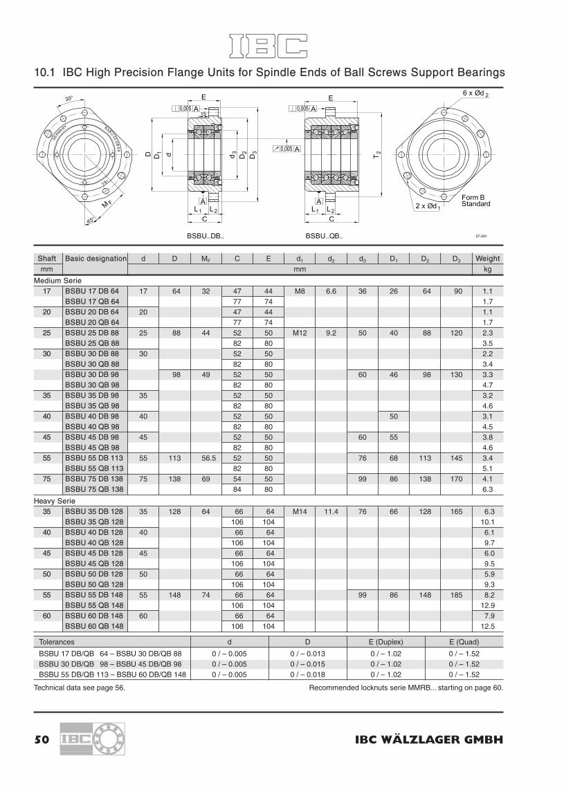
50 IBC WÄLZLAGER GMBH
10.1 IBC High Precision Flange Units for Spindle Ends of Ball Screws Support Bearings
Shaft Basic designation d D MF C E d1 d2 d3 D1 D2 D3 Weightmm mm kg
Medium Serie17 BSBU 17 DB 64 17 64 32 47 44 M8 6.6 36 26 64 90 1.1
BSBU 17 QB 64 77 74 1.720 BSBU 20 DB 64 20 47 44 1.1
BSBU 20 QB 64 77 74 1.725 BSBU 25 DB 88 25 88 44 52 50 M12 9.2 50 40 88 120 2.3
BSBU 25 QB 88 82 80 3.530 BSBU 30 DB 88 30 52 50 2.2
BSBU 30 QB 88 82 80 3.4BSBU 30 DB 98 98 49 52 50 60 46 98 130 3.3BSBU 30 QB 98 82 80 4.7
35 BSBU 35 DB 98 35 52 50 3.2BSBU 35 QB 98 82 80 4.6
40 BSBU 40 DB 98 40 52 50 50 3.1BSBU 40 QB 98 82 80 4.5
45 BSBU 45 DB 98 45 52 50 60 55 3.8BSBU 45 QB 98 82 80 4.6
55 BSBU 55 DB 113 55 113 56.5 52 50 76 68 113 145 3.4BSBU 55 QB 113 82 80 5.1
75 BSBU 75 DB 138 75 138 69 54 50 99 86 138 170 4.1BSBU 75 QB 138 84 80 6.3
Heavy Serie35 BSBU 35 DB 128 35 128 64 66 64 M14 11.4 76 66 128 165 6.3
BSBU 35 QB 128 106 104 10.140 BSBU 40 DB 128 40 66 64 6.1
BSBU 40 QB 128 106 104 9.745 BSBU 45 DB 128 45 66 64 6.0
BSBU 45 QB 128 106 104 9.550 BSBU 50 DB 128 50 66 64 5.9
BSBU 50 QB 128 106 104 9.355 BSBU 55 DB 148 55 148 74 66 64 99 86 148 185 8.2
BSBU 55 QB 148 106 104 12.960 BSBU 60 DB 148 60 66 64 7.9
BSBU 60 QB 148 106 104 12.5
Tolerances d D E (Duplex) E (Quad)
BSBU 17 DB/QB 64 – BSBU 30 DB/QB 88 0 / – 0.005 0 / – 0.013 0 / – 1.02 0 / – 1.52BSBU 30 DB/QB 98 – BSBU 45 DB/QB 98 0 / – 0.005 0 / – 0.015 0 / – 1.02 0 / – 1.52BSBU 55 DB/QB 113 – BSBU 60 DB/QB 148 0 / – 0.005 0 / – 0.018 0 / – 1.02 0 / – 1.52
Technical data see page 56. Recommended locknuts serie MMRB... starting on page 60.
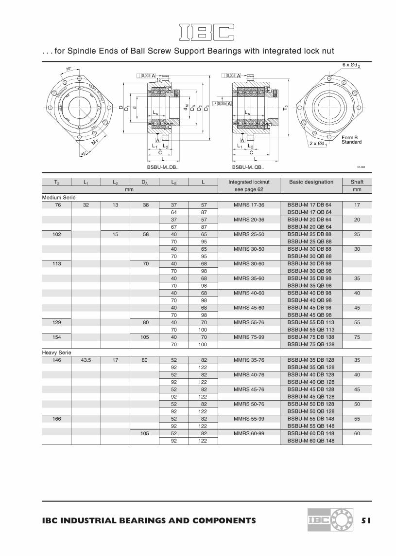
IBC INDUSTRIAL BEARINGS AND COMPONENTS 51
. . . for Spindle Ends of Ball Screw Support Bearings with integrated lock nut
T2 L1 L2 DA LS L Integrated locknut Basic designation Shaftmm see page 62 mm
Medium Serie76 32 13 38 37 57 MMRS 17-36 BSBU-M 17 DB 64 17
64 87 BSBU-M 17 QB 6437 57 MMRS 20-36 BSBU-M 20 DB 64 2067 87 BSBU-M 20 QB 64
102 15 58 40 65 MMRS 25-50 BSBU-M 25 DB 88 2570 95 BSBU-M 25 QB 8840 65 MMRS 30-50 BSBU-M 30 DB 88 3070 95 BSBU-M 30 QB 88
113 70 40 68 MMRS 30-60 BSBU-M 30 DB 9870 98 BSBU-M 30 QB 9840 68 MMRS 35-60 BSBU-M 35 DB 98 3570 98 BSBU-M 35 QB 9840 68 MMRS 40-60 BSBU-M 40 DB 98 4070 98 BSBU-M 40 QB 9840 68 MMRS 45-60 BSBU-M 45 DB 98 4570 98 BSBU-M 45 QB 98
129 80 40 70 MMRS 55-76 BSBU-M 55 DB 113 5570 100 BSBU-M 55 QB 113
154 105 40 70 MMRS 75-99 BSBU-M 75 DB 138 7570 100 BSBU-M 75 QB 138
Heavy Serie146 43.5 17 80 52 82 MMRS 35-76 BSBU-M 35 DB 128 35
92 122 BSBU-M 35 QB 12852 82 MMRS 40-76 BSBU-M 40 DB 128 4092 122 BSBU-M 40 QB 12852 82 MMRS 45-76 BSBU-M 45 DB 128 4592 122 BSBU-M 45 QB 12852 82 MMRS 50-76 BSBU-M 50 DB 128 5092 122 BSBU-M 50 QB 128
166 52 82 MMRS 55-99 BSBU-M 55 DB 148 5592 122 BSBU-M 55 QB 148
105 52 82 MMRS 60-99 BSBU-M 60 DB 148 6092 122 BSBU-M 60 QB 148

52 IBC WÄLZLAGER GMBH
10.2 IBC High Precision Pillow Block Units for Spindle Ends of Ball Screw Support Bearings
Shaft Basic designation d M C E d3 D1 U U1 U2 V1 V2 V3 Weightmm mm kg
Medium Serie17 BSPB 17 D 32 17 32 47 44 36 26 94 47 17 62 32 15 1.5
BSPB 17 Q 32 77 74 2.620 BSPB 20 D 32 20 47 44 1.5
BSPB 20 Q 32 77 74 2.625 BSPB 25 D 42 25 42 52 50 50 40 125 62.5 20 82 42 2.8
BSPB 25 Q 42 82 80 4.630 BSPB 30 D 42 30 52 50 2.7
BSPB 30 Q 42 82 80 4.5BSPB 30 D 50 50 52 50 60 46 136 68 20.5 95 50 3.9BSPB 30 Q 50 82 80 6.3
35 BSPB 35 D 50 35 52 50 3.8BSPB 35 Q 50 82 80 6.2
40 BSPB 40 D 50 40 52 50 50 3.7BSPB 40 Q 50 82 80 6.0
45 BSPB 45 D 50 45 52 50 60 55 3.6BSPB 45 Q 50 82 80 5.9
55 BSPB 55 D 65 55 65 52 50 76 68 154 77 23 118 65 30 4.5BSPB 55 Q 65 82 80 7.2
75 BSPB 75 D 65 75 65 54 50 99 86 174 87 129 5.0BSPB 75 Q 65 84 80 8.0
Heavy Serie35 BSPB 35 D 65 35 65 66 64 76 66 190 95 30 130 65 15 9.7
BSPB 35 Q 65 106 104 15.940 BSPS 40 D 65 40 66 64 9.5
BSPB 40 Q 65 106 104 15.745 BSPB 45 D 65 45 66 64 9.3
BSPB 45 Q 65 106 104 15.450 BSPB 50 D 65 50 66 64 9.1
BSPB 50 Q 65 106 104 15.155 BSPB 55 D 85 55 85 66 64 99 86 200 100 155 85 9.1
BSPB 55 Q 85 106 104 15.160 BSPB 60 D 85 60 66 64 9.1
BSPB 60 Q 85 106 104 15.1
Tolerances d M U1 E (Duplex) E (Quad)
BSPB 17 D/Q 32 – BSPB 30 D/Q 42 0 / – 0.005 0 / – 0.013 0 / – 0.013 0 / – 1.02 0 / – 1.52BSPB 30 D/Q 50 – BSPB 45 D/Q 50 0 / – 0.005 0 / – 0.015 0 / – 0.015 0 / – 1.02 0 / – 1.52BSPB 55 D/Q 65 – BSPB 60 D/Q 85 0 / – 0.005 0 / – 0.018 0 / – 0.018 0 / – 1.02 0 / – 1.52
Technical data see page 56. Recommended locknuts serie MMRB... starting on page 60.

IBC INDUSTRIAL BEARINGS AND COMPONENTS 53
. . . for Spindle Ends of Ball Screw Support Bearings with integrated lock nut
Y1 Y2 Y3 Z1 Z2 d4 d5 DA LS L Integrated locknut Basic designation Shaftmm see page 62 mm
Medium Serie38 22.0 9 8.5 85.5 9 7.8 38 37 57 MMRS 17-36 BSPB-M 17 D 32 1768 67 87 BSPB-M 17 Q 3238 37 57 MMRS 20-36 BSPB-M 20 D 32 2068 67 87 BSPB-M 20 Q 3242 25.0 10 10 115.0 11 9.8 58 40 65 MMRS 25-50 BSPB-M 25 D 42 2572 70 95 BSPB-M 25 Q 4242 40 65 MMRS 30-50 BSPB-M 30 D 42 3072 70 95 BSPB-M 30 Q 4242 126.0 13 70 40 68 MMRS 30-60 BSPB-M 30 D 5072 70 98 BSPB-M 30 Q 5042 40 68 MMRS 35-60 BSPB-M 35 D 50 3572 70 98 BSPB-M 35 Q 5042 40 68 MMRS 40-60 BSPB-M 40 D 50 4072 70 98 BSPB-M 40 Q 5042 40 68 MMRS 45-60 BSPB-M 45 D 50 4572 70 98 BSPB-M 45 Q 5040.5 26.0 11.5 11.5 142.5 80 40 70 MMRS 55-76 BSPB-M 55 D 65 5570.5 70 100 BSPB-M 55 Q 6540.5 162.5 105 40 70 MMRS 75-99 BSPB-M 75 D 65 7570.5 70 100 BSPB-M 75 Q 65
Heavy Serie53 32.0 13 15 175.0 18 11.8 80 52 82 MMRS 35-76 BSPB-M 35 D 65 3593 92 122 BSPB-M 35 Q 6553 52 82 MMRS 40-76 BSPB-M 40 D 65 4093 92 122 BSPB-M 40 Q 6553 52 82 MMRS 45-76 BSPB-M 45 D 65 4593 92 122 BSPB-M 45 Q 6553 52 82 MMRS 50-76 BSPB-M 50 D 65 5093 92 122 BSPB-M 50 Q 6553 185.0 52 82 MMRS 55-99 BSPB-M 55 D 85 5593 92 122 BSPB-M 55 Q 8553 105 52 82 MMRS 60-99 BSPB-M 60 D 85 6093 92 122 BSPB-M 60 Q 85

54 IBC WÄLZLAGER GMBH
10.3 IBC High Precision Flange Units for Ball Screw Nuts
KGT Basic designation d D M C H d1 d2 d3 d4 D1 D2 D3 T1 T2 L1 L2 L3 Hole
do x P mm pattern
16x 5 BNBU 28 DB 98 28 98 49 52 70 M5 9.2 60 M12 70 98 130 38 113 32 15 2 1
20x 5 BNBU 36 DB 98 36 52 70 M6 47
25x 5 BNBU 40 DB 113 40 113 56.5 52 70 76 80 113 145 51 12925x10 BNBU 40 QB 113 82 10032x 5 BNBU 50 DB 138 50 138 69 54 70 M8 99 105 138 170 65 154 432x10 BNBU 50 QB 138 84 10040x 5 BNBU 63 DB 138 63 54 70 78 240x10 BNBU 63 QB 138 84 10050x 5 BNBU 75 DB 178 75 178 89 77 101 M10 11.4 132 M14 140 178 215 93 197 50 2050x10 BNBU 75 QB 178 122 14663x 5 BNBU 90 DB 210 90 210 105 77 105 162 175 210 248 108 23063x10 BNBU 90 QB 210 122 15063x20 BNBU 95 DB 210 95 77 105 M12 115
BNBU 95 QB 210 122 15080x10 BNBU 105 DB 210 105 77 105 125
BNBU 105 QB 210 122 150
Technical data see page 27
Tolerances Housing d D
BNBU 28 DB/QB 98 – BNBU 36 D/Q 98 + 0.003 / – 0.010 0 / – 0.015BNBU 40 DB/QB 113 – BNBU 105 D/Q 210 + 0.003 / – 0.010 0 / – 0.018
Adapter sleeves for other bs nuts on request.
Order example:For a ballscrew Ø 63 x 10 with abutment dimension acc. to DIN 69051 a standard flange unit with hole pattern no. 2 andtwo bearings are needed as shown.Medium preload is chosen: BNBU 90DB210. 2.M.M2
Mounting M1: connecting thread on right side, mounted opposite to mounting seat D.
For bearing units with integrated lubrication ofball screw nuts, please ask for separate datasheets (Serie BNBUS).

IBC INDUSTRIAL BEARINGS AND COMPONENTS 55
10.4 IBC High Precision Pillow Block Units for Ball Screw Nuts
KGT Basic designation d M C H d1* d3 d4 d5 D1 D4 T1 U U1 U2 V1 V2 V3 Y1 Y2 Y3 Z1 Z2 Bdo x P mm
16x 5 BNPB 28 D 50 28 50 52 70 M5 60 13 9.8 55 70 38 136 68 20.5 98 50 20 42 25.0 10 10 126.0 1
20x 5 BNPB 36 D 50 36 52 70 M6 47
25x 5 BNPB 40 D 65 40 65 52 70 76 68 80 51 154 77 23 118 65 40.5 26.0 11.5 11.5 142.525x10 BNPB 40 Q 65 82 100 70.532x 5 BNPB 50 D 65 50 54 70 M8 99 89 105 65 174 87 129 40.5 162.532x10 BNPB 50 Q 65 84 100 70.540x 5 BNPB 63 D 65 63 54 70 78 40.5 240x10 BNPB 63 Q 65 84 100 70.550x 5 BNPB 75 D 85 75 85 77 101 M10 132 18 11.8 114 140 93 230 115 30 170 85 30 57 37.0 17 15 215.050x10 BNPB 75 Q 85 122 146 10063x 5 BNPB 90 D 105 90 105 77 105 162 21 140 175 108 280 140 35 207 105 50 57 17 263.063x10 BNPB 90 Q 105 122 150 10063x20 BNPB 95 D 105 95 77 105 M12 115 57
BNPB 95 Q 105 122 150 10080x10 BNPB 105 D 105 105 77 105 125 57
BNPB 105 Q 105 122 150 100
* preferable to be mounted with socket head cap screws to DIN 912, tensile strength class 8.8
Tolerances Housing d M U1
BSPB 28 D/Q 50 – BNPB 36 D/Q 50 + 0.003 / 0.010 0 / – 0.015 0 / – 0.013BSPB 40 D/Q 65 – BNPB 63 D/Q 65 + 0.003 / 0.010 0 / – 0.018 0 / – 0.015BSPB 75 D/Q 85 – BNPB 105 D/Q 105 + 0.003 / 0.010 0 / – 0.018 0 / – 0.018
Adapter sleeves for other bs nuts on request.
Order example:For a ballscrew Ø 80 x 10 heavy load with 4 bearings, adapter hole pattern No. 2 according to DIN 69051, light preload,mounted as shown above: BNPB 105Q105 2.L.M2
(Mounting M1: connecting thread on right side, mounted below outer locknut).

56 IBC WÄLZLAGER GMBH
10.5 Technical Data Table of Flange and Pillow Block Units
BSBU..DB.. BSBU-M..DB.. BSPB..D.. BSPB-M..D..BSBU..QB.. BSBU-M..QB.. BSPB..Q.. BSPB-M..Q..
Basic designation Axial capacity Preload Fv Ax. stiffness Sax Speed grease nF Drag troque Mr
BSBU BSPB Ca Coa L M H L M H L M H L M HBSBU-M BSPB-M N N N/µm min–1 Nm
Duplex SerieBSBU 17 DB 64 BSPB 17 D 32 25 000 32 000 875 1 750 3 500 450 570 730 14 300 12 500 6 200 0.08 0.16 0.32BSBU 20 DB 64 BSPB 20 D 32BSBU 25 DB 88 BSPB 25 D 42 29 200 43 600 1 125 2 250 4 500 640 810 1 030 10 500 9 100 4 500 0.11 0.22 0.43BSBU 30 DB 88 BSPB 30 D 42BSBU 30 DB 98 BSPB 30 D 50 35 600 55 000 1 700 3 400 6 800 770 970 1 240 8 600 7 500 3 700 0.11 0.22 0.43BSBU 35 DB 98 BSPB 35 D 50BSBU 40 DB 98 BSPB 40 D 50BSBU 45 DB 98 BSPB 45 D 50 37 900 62 000 1 700 3 400 6 800 770 970 1 240 8 000 7 000 3 500 0.14 0.28 0.56BSBU 55 DB 113 BSPB 55 D 65 40 700 74 000 1 975 3 950 7 900 1 020 1 300 1 640 6 900 6 000 3 000 0.22 0.42 0.82BSBU 75 DB 138 BSPB 75 D 65 44 500 94 000 2 500 5 000 10 000 1 320 1 650 2 120 5 200 4 500 2 250 0.26 0.50 1.00
Heavy SerieBSBU 35 DB 128 BSPB 35 D 65 70 500 116 000 3 200 6 400 12 800 1 050 1 360 1 740 6 400 5 600 2 800 0.26 0.51 1.07BSBU 40 DB 128 BSPB 40 D 65BSBU 45 DB 128 BSPB 45 D 65BSBU 50 DB 128 BSPB 50 D 65BSBU 55 DB 148 BSPB 55 D 85 80 800 137 800 3 900 7 800 15 600 1 320 1 650 2 120 5 300 4 600 2 300 0.34 0.68 1.36BSBU 60 DB 148 BSPB 60 D 85
Quadruplex SerieBSBU 17 QB 64 BSPB 17 Q 32 40 600 64 000 1 750 3 500 7 000 900 1 040 1 460 10 000 8 700 4 300 0.16 0.32 0.64BSBU 20 QB 64 BSPB 20 Q 32BSBU 25 QB 88 BSPB 25 Q 42 47 500 86 000 2 250 4 500 9 000 1 280 1 620 2 060 7 300 6 300 3 100 0.22 0.43 0.86BSBU 30 QB 88 BSPB 30 Q 42BSBU 30 QB 98 BSPB 30 Q 50 57 800 110 000 3 400 6 800 13 600 1 540 1 940 2 480 6 000 5 200 2 600 0.22 0.43 0.86BSBU 35 QB 98 BSPB 35 Q 50BSBU 40 QB 98 BSPB 40 Q 50BSBU 45 QB 98 BSPB 45 Q 50 61 600 123 000 3 400 6 800 13 600 1 540 1 940 2 480 5 600 4 900 2 400 0.28 0.56 1.02BSBU 55 QB 113 BSPB 55 Q 65 66 100 178 000 3 950 7 900 15 800 2 040 2 600 3 280 4 800 4 200 2 100 0.44 0.84 1.64BSBU 75 QB 138 BSPB 75 Q 65 72 300 188 000 5 000 10 000 20 000 2 640 3 300 4 240 3 500 3 100 1 550 0.52 1.00 2.00
Heavy SerieBSBU 35 QB 128 BSPB 35 Q 65 114 500 232 000 6 400 12 800 25 600 2 100 2 720 3 480 4 450 3 900 1 950 0.52 1.02 2.04BSBU 40 QB 128 BSPB 40 Q 65BSBU 45 QB 128 BSPB 45 Q 65BSBU 50 QB 128 BSPB 50 Q 65BSBU 55 QB 148 BSPB 55 Q 85 131 000 274 000 7 800 15 600 31 200 2 640 3 300 4 220 3 700 3 200 1 600 0.68 1.36 2.72BSBU 60 QB 148 BSPB 60 Q 85
with adapter sleeve for ball screw nuts acc. to DIN 69051 BNBU..DB.., BNBU..QB.., BNPB..D... BNPB..Q..
KGT Basic designation Axial capacity Preload Fv Ax. stiffness Sax Speed grease nF Drag troque Mr
do x P BNBU BNPB Ca Coa L M H L M H L M H L M HBNBU-M BNPB-M N N N/µm min–1 Nm
16x 5 BNBU 28 DB 98 BNPB 28 D 50 37 900 62 000 1 700 3 400 6 800 840 1 050 1 330 8 600 7 500 3 700 0.14 0.28 0.5620x 5 BNBU 36 DB 98 BNPB 36 D 50 37 900 62 000 1 700 3 400 6 800 840 1 050 1 330 8 600 7 500 3 700 0.14 0.28 0.5625x 5 BNBU 40 DB 113 BNPB 40 D 65 40 700 74 000 1 975 3 950 7 900 1 010 1 260 1 610 6 900 6 000 3 000 0.22 0.42 0.3225x10 BNBU 40 QB 113 BNPB 40 Q 65 66 100 148 000 3 900 7 800 15 600 2 050 2 560 3 250 4 800 4 200 2 100 0.44 0.84 1.6432x 5 BNBU 50 DB 138 BNPB 50 D 65 44 500 94 000 2 500 5 000 10 000 1 230 1 570 2 010 5 200 4 500 2 250 0.26 0.50 1.0032x10 BNBU 50 QB 138 BNPB 50 Q 65 72 300 188 000 5 000 10 000 20 000 2 500 3 180 4 100 3 500 3 100 1 550 0.52 1.00 2.0040x 5 BNBU 63 DB 138 BNPB 63 D 65 44 500 94 000 2 500 5 000 10 000 1 230 1 570 2 010 5 200 4 500 2 250 0.26 0.50 1.0040x10 BNBU 63 QB 138 BNPB 63 Q 65 72 300 188 000 5 000 10 000 20 000 2 500 3 180 4 100 3 500 3 100 1 550 0.52 1.00 2.0050x 5 BNBU 75 DB 178 BNPB 75 D 65 86 400 192 000 5 200 10 400 20 800 1 800 2 280 2 900 3 800 3 300 1 650 0.27 0.53 1.0650x10 BNBU 75 QB 178 BNPB 75 Q 65 140 000 384 000 10400 20 800 41 600 3 600 4 560 5 800 2 600 2 300 1 150 0.54 1.06 2.1263x 5 BNBU 90 DB 210 BNPB 90 D 105 85 200 240 000 4 550 9 100 18 200 1 950 2 500 3 150 3 100 2 700 1 350 0.27 0.54 1.0863x10 BNBU 90 QB 210 BNPB 90 Q 105 138 000 480 000 9 100 18 200 36 400 3 900 5 000 6 300 2 100 1 900 950 0.54 1.08 2.1663x20 BNBU 95 DB 210 BNPB 95 D 105 85 200 240 000 4 550 9 100 18 200 1 950 2 500 3 150 3 100 2 700 1 350 0.27 0.54 1.08
BNBU 95 QB 210 BNPB 95 Q 105 138 000 480 000 9 100 18 200 36 400 3 900 5 000 6 300 2 100 1 900 950 0.54 1.08 2.1680x10 BNBU 105 DB 210 BNPB 105 D 105 85 200 240 000 4 550 9 100 18 200 1 950 2 500 3 150 3 100 2 700 1 350 0.27 0.54 1.08
BNBU 105 QB 210 BNPB 105 Q 105 138 000 480 000 9 100 18 200 36 400 3 900 5 000 6 300 2 100 1 900 950 0.54 1.08 2.16
On request a speed increase of 35 % is possible by use of ceramic balls. Then the static capacity Coa will be reduced to 70 %.

IBC INDUSTRIAL BEARINGS AND COMPONENTS 57
10.6 IBC High Precision Floating End Units
Shaft Designation d M C C1 C2 D1 D2 U U1 U2 U3 V1 V2 V3 Y1 Y2 Z1 Z2 d4 d5 C Comm mm N20 BLPB 20 N 32 20 32 30 18 6 37 25 94 47 16 56 59 15 15 24.0 12 8.5 85.5 9 5.8 17 300 19 90025 BLPB 25 N 42 25 42 30 18 6 42 30 125 62.5 21 70 77 22 20 24.0 12 10 115 9 5.8 19 300 24 20030 BLPB 30 N 50 30 50 30 18 6 47 35 136 68 21 80 88 28 20 24.0 12 10 126 9 5.8 21 100 28 50040 BLPB 40 N 65 40 65 40 23 8.5 62 48 190 95 30 100 108 38 20 30.0 15 15 175 13 7.8 36 000 53 00050 BLPB 50 N 85 50 85 40 23 8.5 72 58 200 100 30 110 138 48 30 30.0 15 15 185 13 7.8 40 000 64 000
Tolerances M U1
BLPB 20 N 32 0 / –0.013 0 / –0.013BLPB 25 N 42 0 / –0.013 0 / –0.013BLPB 30 N 50 0 / –0.015 0 / –0.015BLPB 40 N 65 0 / –0.018 0 / –0.018BLPB 50 N 85 0 / –0.018 0 / –0.018
d according PN DIN 620Maximum speed see cartridge bearing unit
Tolerances of Cartridge Bearing Units
Inner Diameter d PN DIN 620Cartridge Diameter D 32 – 80 0 / –0.013
85 – 90 0 / –0.015
Super Precision Pillow Block Bearing Unitsfor Supporting Floating End of Shaft
BLPB..N.. .2RS
Cartridge Bearing Units forSupporting Floating End of Shaft
BLBU..N... 2RS
Shaft Designation d D C C1 C2 D1 D2 D3 L T d2 ngrease C Comm mm min–1 N
10 BLBU 10 N 32 10 32 25 14 5.5 22 14 52 6 42 4.5 13 000 6 800 6 90012 BLBU 12 N 35 12 35 25 14 5.5 24 16 55 6 45 4.5 12 000 7 600 8 30017 BLBU 17 N 40 17 40 26 14 6 30 20 60 6 50 4.5 9 000 8 800 11 00020 BLBU 20 N 50 20 50 30 18 6 37 25 70 8 60 4.5 7 500 17 300 19 90025 BLBU 25 N 55 25 55 30 18 6 42 30 75 8 65 4.5 6 500 19 300 24 20030 BLBU 30 N 60 30 60 32 18 6 47 35 80 8 70 4.5 5 500 21 100 28 50035 BLBU 35 N 70 35 70 38 21 8.5 55 42 90 10 80 5.5 4 800 26 500 39 50040 BLBU 40 N 80 40 80 43 23 10 62 48 110 10 95 5.5 4 200 36 000 53 00045 BLBU 45 N 85 45 85 43 23 10 68 52 110 10 98 5.5 3 900 38 000 59 00050 BLBU 50 N 90 50 90 44 23 10.5 72 58 120 10 105 5.5 3 500 40 000 64 000

58 IBC WÄLZLAGER GMBH
10.7 Mounting Dimensions for Ball Screw Spindles
BSBU-M..DB..BSPB-M..D..
BSBU-M..QB..BSPB-M..Q..
BLBU..N..
Fixed end Centre Floating endheight
Basic d1 d2 d3 DA LD LD1 LQ LQ1 L2 r1max M d5 d6 L3 L4 L5 r2max Basicdesignation 4h/6h j5 h11 designation
mm
Medium SerieBSPB-M 17.32 17 23 M 17 x 1 38 57 36 87 65 24 0.5 32 20 19.2 18 1.2 6 0.3 BLPB-20N32BSPB-M 20.32 20 26 M 20 x 1BSPB-M 25.42 25 35 M 25 x 1.5 58 65 39 95 68 29 0.8 42 25 24 18 1.2 6 0.3 BLPB-25N42BSPB-M 30.42 30 37 M 30 x 1.5BSPB-M 30.50 30 37 M 30 x 1.5 70 68 39 98 68 32 0.8 50 30 29 18 1.5 6 0.3 BLPB-30N50BSPB-M 35.50 35 42 M 35 x 1.5BSPB-M 40.50 40 47 M 40 x 1.5BSPB-M 45.50 45 53 M 45 x 1.5BSPB-M 55.65 55 63 M 55 x 2 80 70 39 100 68 34 0.8 65 50 48.5 23 1.5 8.5 0.6 BLPB-50N85BSPB-M 75.65 75 84 M 75 x 2 105
Heavy SerieBSPB-M 35.65 35 43 M 35 x 1.5 80 82 51 122 90 34 0.8 65 40 38.5 23 1.5 8.5 0.6 BLPB-40N65BSPB-M 40.65 40 48 M 40 x 1.5BSPB-M 45.65 45 54 M 45 x 1.5BSPB-M 50.65 50 59 M 50 x 1.5BSPB-M 55.85 55 65 M 55 x 2 105 82 51 90 34 85 50 48.5 23 1.5 8.5 0.6 BLPB-50N85BSPB-M 60.85 60 70 M 60 x 2
The following cartridge units have the samedimensions as pillow block units:
Medium Serie Tolerance d1 [µm]
BSBU-M 17.64 BSPB-M 17.32 – 3 / – 7BSBU-M 20.64 BSPB-M 20.32BSBU-M 25.88 BSPB-M 25.42 – 3 / – 7BSBU-M 30.88 BSPB-M 30.42BSBU-M 30.98 BSPB-M 30.50 – 4 / – 8BSBU-M 35.98 BSPB-M 35.50BSBU-M 40.98 BSPB-M 40.50BSBU-M 45.98 BSPB-M 45.50 – 4 / – 8BSBU-M 55.113 BSPB-M 55.65 – 4 / – 9BSBU-M 75.138 BSPB-M 75.65 – 4 / – 9
Heavy Serie
BSBU-M 35.128 BSPB-M 35.65 – 4 / – 8BSBU-M 40.128 BSPB-M 55.85BSBU-M 45.128 BSPB-M 45.65BSBU-M 50.128 BSPB-M 50.65BSBU-M 55.148 BSPB-M 55.85 – 4 / – 9BSBU-M 60.148 BSPB-M 60.85
Same reference dimensions (U1, M)for fixed and floating end units simplifymounting of belt driven assemblies.
Longer fixed end units with space for integrated coupling and hole pattern formotor mounting on demand.
57-602

IBC INDUSTRIAL BEARINGS AND COMPONENTS 59
11.0 Introduction IBC Precision Locknuts and Labyrinth Seals
Fields of applicationIBC Precisions Locknuts with fine thread are used for high-precision application. Due to integrated safety systems inthe various locknuts, an easy and precise mounting, as wellas safeguarding of locknuts is guaranteed.Installation of lockwashers within an axial groove is nolonger necessary. The material cross section is maintainedand the notch effect is not increased. Additionally axialprecision is enhanced.
TolerancesA high accuracy of the axial eccentricity according to IT3,ISO basic tolerances according to DIN 7151, will beachieved by precision-machining the inner thread with itslocking device and the face in one operation.These locking devices, which are also profiled, bear on thethread flanks. The thread is manufactured with a toleranceof 4H according to DIN 13 T21-24 and from M210x4 onthe tolerance is 6H.
DesignFor compact applications (lightest weight), series MMRPrecision Locknuts are used. The Precision Locknuts inrecessed locations which cannot be reached radially(housing bores) are secured using the axially accessiblesocket set screws on the MMA, MBA and MBC series.This option requires a larger width because of the innerconstruction. From Ø 20 on, the MBA model is supplied.The permissible axial load corresponds to the MMR Preci-sion Locknut. In the range of Ø 45 ... 200 mm also the Pre-cision Locknut MBC with four axial securable socket headcap screws at its end are produced.The same cross section as for the MBA and MBC is usedfor the MMRB with radial securing system. The later per-mits larger loads and tightening torques. This is favorablein particular for preloading bearings supporting a high axi-al load (in ball screws, for instance).
Precision Locknuts with Labyrinth SealThe MMRBS and MBAS series additionally have a set oflaminar rings made out of spring steel, which may create acompact labyrinth seal in conjunction with the housingwhere limited space is available. The intermediate spaceof the labyrinth area must be filled with grease before andafter mounting.The cross section of the series MMRS Precision Locknutswith similar properties as MMRBS Precision Locknutswere designed to match the series BS 60° Super Preci-sion Angular Contact Thrust Ball Bearings and the MDSeal Nuts (see page 62, 63). These are available in thestandard sizes as well as in special sizes (different crosssection) or made of stainless steel or with ATCoat.
Abutment and Fillet DimensionsThe recommended tolerance of the counter thread of theshaft is “medium” 6g, 6h or “fine” 4h for higher accuracyrequirements (machine tools).
Strength of the Precision Locknut ThreadsThreads up to M50: 1000 N/mm2
Threads M50 and larger: 650 N/mm2
The permissible axial loads are applicable to bolt threadswith a tensile strength of at least 700 N/mm2. In case ofdynamic load, 75 % of axial load Fa is permissible.
MountingPrecision Locknut should be screwed on the shaft with alllocking devices in unchanged position. Use spanners totighten the locknuts with approximately triple of the nomi-nal torque (to avoid setting of the clamped parts, loosenand retighten them applying the nominal torque).Tightening of the locking devices lightly increases the axialforces of precision locknuts of MBA design. The effect ofthe MBC designed Precision Locknut is contrary andmust not be used for bearings with grounded preload. Thenecessary tightening torque depends on the required pre-load of the bearings and the required pressfit between theinner rings and the shaft. Additional information seeTI-I-5020.0 / E page 8 and 9.
Securing against looseningLightly tighten the first socket set screw until you noticeresistance. Tighten second screw located opposite.If existing, tighten third screw (only in case of MMRB,MMRBS and MMRS) as well as fourth screw in case ofversion …Q. Retighten the screws. For maximum tighten-ing torques of the socket set screws and socket head capscrews, please refer to the following table.
Securing Spanner size [mm] Max tightening torque MA [Nm]thread S SMBC socket set socket head
screws cap screwsM4 2 3 2 4.5M5 2.5 4 4 8.5M6 3 5 7 15M8 4 6 18 36M10 5 – 34 –M12 6 – 60 –
Table: Maximum tightening torques of securing devicesin Precision Locknuts
This results in high loosening torques to prevent unin-tended loosening even for spindles running clockwise andcounter-clockwise intermittently as well as for high speedacceleration of spindle.
DisassemblyLoosen locking devices first for disassembly. As clampingdoes not deform the profiled securing elements made fromhard bronze, the nut can be used repeatedly after loosen-ing.
Designation for IBC Precision Locknutsand Labyrinth SealsMMR narrow Precision Locknut with radial lockMMRB wide Precision Locknut with radial lockMMRBS the same as MMRB, but with laminar Labyrinth
SealMBA Precision Locknut with axial lock via slotted seg-
mentsMBAS the same as MBA, but with laminar Labyrinth SealMBC Precision Locknut with axial lock via slotted seg-
ments and four screwsMMA Precision Locknut with axial lock via 2 conesMMRS special locknut with radial lock, to match 60°
super precision angular contact thrust ball bear-ings BS and MD Locknut
MD Seal Nut with fine outer thread, fits to LabyrinthSeals S and MMRS nut
S Precision Labyrinth Seal with laminar rings madeof spring steel
. . . . Q 4 securing elements, unless standard
58-704

60 IBC WÄLZLAGER GMBH
11.1 IBC Precision Locknuts MMR, MMRB, MMRBS, MMA, MBA, MBAS, MBC
Thread Designation Dimensions Max. Permissibletightening torque axial load
set screws MMR MMAMS MMRB MBA
MBCTolerance Radial lock- Axial lock- DA h g t d1 c ma mr mc h1 h2 E** MMR MBA MBC Fa4H ing system ing system MMRB
MMR, MMRB/ MBA/MBAS rad. ax.MMRBS MBC mm Nm kN
M 6 x 0.5 MMR 6 16 8 3 2 12 4 – M 4 – – 2 – 16M 8 x 0.75 MMR 8 17M 10 x 0.75 MMR 10 18 14 22M 12 x 1 MMR 12 22 18 26M 15 x 1 MMR 15 25 21 33M 17 x 1 MMR 17 28 10 4 23 5 M 5 4 49
MMA 17 * 16 M 4 2 70 70M 20 x 1 MMR 20 32 10 27 55
MMRB 20 MB_ _ 20 16 4.4 2.9 32 110 110M 20 x 1.5 MMR 20 x 1.5 10 70
MMRB 20 x 1.5 MB_ _ 20 x 1.5 16 32 110 110M 25 x 1.5 MMR 25 38 12 5 33 6 M 6 7 87
MMRB 25 MB_ _ 25 18 38 130 130M 30 x 1.5 MMR 30 45 12 40 5.2 3.2 110
MMRB 30 MB_ _ 30 18 M 6 45 7 150 150M 35 x 1.5 MMR 35 52 12 47 120
MMRB 35 MB_ _ 35 18 52 170 120M 40 x 1.5 MMR 40 58 14 6 2.5 52 7 150
MMRB 40 MB_ _ 40 20 58 210 150M 45 x 1.5 MMR 45 65 14 59 6 3.6 170
MMRB 45 MB_ _ 45 20 M 4 65 4.5 240 170M 50 x 1.5 MMR 50 70 14 64 180
MMRB 50 MB_ _ 50 20 70 260 180M 55 x 2 MMR 55 75 16 7 3 68 8 M 8 18 18 250
MMRB 55 MB_ _ 55 22 M 8 75 340 250M 60 x 2 MMR 60 80 16 73 270
MMRB 60 MB_ _ 60 22 80 360 270M 65 x 2 MMR 65 85 16 78 290
MMRB 65 MB_ _ 65 22 85 400 290M 70 x 2 MMR 70 92 18 8 3.5 85 9 350
MMRB 70 MB_ _ 70 24 92 470 350M 75 x 2 MMR 75 98 18 90 370
MMRB 75 MB_ _ 75 24 M 5 98 8.5 500 370M 80 x 2 MMR 80 105 18 95 7.3 4.3 390
MMRB 80 MB_ _ 80 24 105 520 390M 85 x 2 MMR 85 110 18 102 M 10 34 34 400
MMRB 85 MB_ _ 85 24 M 10 110 540 400
* Securing: 2 cones at 90°E** see page 60 MMRBS. Special sizes available: MMR 16 x 1.5 Q; MMR 33 x 1.5 Q;MMR 42 x 1.5 Q; MMR 60 x 1.5 Q; MMR 65 x 1.5 Q; MMR 145 x 2 Q.
Table 58-700: IBC Precision Locknuts MMR, MMRB, MMRBS, MMA, MBA, MBAS, MBC Further sizes are available on inquiry.
MMR.. MBA.. MBC..MBC..

IBC INDUSTRIAL BEARINGS AND COMPONENTS 61
IBC Precision Locknuts MMR, MMRB, MMRBS, MMA, MBA, MBAS, MBC
Thread Designation Dimensions Max. Permissibletightening torque axial load
socket screws MMR MMAMS MMRB MBA
MBCTolerance* Radial lock- Axial lock- DA h g t d1 c mr mc h1 h2 E** MMR MBC Fa4H ing system ing system ma MMRB
MMR, MMRB/ MBA/MBAS MBAMMRBS MBC mm Nm kN
M 90 x 2 MMR 90 120 20 10 4 108 9 M 10 7.3 4.3 34 470MMRB 90 MB_ _ 90 26 M 6 120 15 610 470
M 95 x 2 MMR 95 125 20 113 490MMRB 95 MB_ _ 95 26 125 640 490
M 100 x 2 MMR 100 130 20 120 510MMRB 100 MB_ _ 100 26 130 660 510
M 105 x 2 MMR 105 140 22 12 5 126 560MMRB 105 MB_ _ 105 28 140 700 560
M 110 x 2 MMR 110 145 22 133 600MMRB 110 MB_ _ 110 28 145 770 600
M 115 x 2 MMR 115 150 22 137 7.5 4.4 660MMRB 115 MB_ _ 115 28 150 820 660
M 120 x 2 MMR 120 155 24 138 710MMRB 120 MB_ _ 120 30 155 890 710
M 125 x 2 MMR 125 160 24 148 740MMRB 125 MB_ _ 125 30 160 920 740
M 130 x 2 MMR 130 165 24 149 760MMRB 130 MB_ _ 130 30 M 8 165 36 950 760
M 140 x 2 MMR 140 180 26 14 6 160 10 M 12 60 880MMRB 140 MB_ _ 140 32 180 1 080 880
M 150 x 2 MMR 150 195 26 171 930MMRB 150 MB_ _ 150 32 195 1 040 930
M 160 x 3 MMRB 160 MB_ _ 160 205 34 16 7 182 8.3 5.3 205 1 360 1 020M 170 x 3 MMRB 170 MB_ _ 170 220 198 220 1 430 1 075M 180 x 3 MMRB 180 MB_ _ 180 230 36 18 8 203 230 1 600 1 200M 190 x 3 MMRB 190 MB_ _ 190 240 214 240 1 670 1 250M 200 x 3 MMRB 200 MB_ _ 200 250 38 226 250 1 850 1 390M 210 x 4 MMRB 210 270 40 20 10 238 14 M 14 10 6.4 270 85 2 000M 220 x 4 MMRB 220 280 250 280 2 250M 240 x 4 MMRB 240 300 44 270 300 2 300M 260 x 4 MMRB 260 310 290 310 2 500M 280 x 4 MMRB 280 330 50 24 310 11 6.6 330 2 850M 300 x 5 MMRB 300 360 336 360 3 100
Face runout T acc. to IT3, DIN 7151; *above Ø 200 : 6H
nK: no. of securing devices = 4
MBAS, MMRBS = MBA, MMRB + Laminar spring steel rings (labyrinth seal)
E** = Bore diameter of counterpart = DA+0+0.1 … and a 25° chamfer for the sealing (see also MMRS),
where the feeding diameter is 4 % larger than DA.
Table 58-701: IBC Precision Locknuts MMR, MMRB, MMRBS, MMA, MBA, MBAS, MBC Further sizes are available on inquiry.
MMRB.. MMRBS.. MBAS..

62 IBC WÄLZLAGER GMBH
11.2 IBC Precision Labyrinth Locknuts MMRS
The Precision Labyrinth Locknut with the mounted laminarspring-steel rings are forming a non-contact seal with anadjusted housing or with a MD series Seal Nut (see page 63and 64).Whereas the Labyrinth Locknut is rotating with the shaft,the spring steel rings are not rotating. They are preloadedradially by the internal diameter of the housing or by theMD Seal Nut. The free space has to be filled with the same
Thread Designation Dimensions Tightening Per-torque missible
set axialscrews load
E DA h g t d1 l m j k N S MS Fa
mm Nm kN
M 17 x 1 MMRS 17-36.Q2 36 38 20 5 2 32 15.5 M 5 9 11 37.5 36 4 100M 20 x 1 MMRS 20-36.Q2 110M 22 x 1 MMRS 22-36.Q2 110M 25 x 1.5 MMRS 25-50.Q2 50 58 25 6 2.5 46 19 M 6 10 13 52 55 7 150M 27 x 1.5 MMRS 27-50.Q2M 30 x 1.5 MMRS 30-50.Q2 180M 30 x 1.5 MMRS 30-60.Q2 60 70 28 56 21 M 8 63 65 18 180M 35 x 1.5 MMRS 35-60.Q2 190M 40 x 1.5 MMRS 40-60.Q2 210M 45 x 1.5 MMRS 45-60.Q2 260M 35 x 1.5 MMRS 35-76.Q2 76 80 30 7 3 72 23 15 79.5 75 290M 40 x 1.5 MMRS 40-76.Q2 340M 45 x 1.5 MMRS 45-76.Q2 400M 50 x 1.5 MMRS 50-76.Q2 420M 55 x 2 MMRS 55-76.Q2 450M 55 x 2 MMRS 55-99.Q2 99 105 8 3.5 95 103 95 450M 60 x 2 MMRS 60-99.Q2 480M 65 x 2 MMRS 65-99.Q2 480M 75 x 2 MMRS 75-99.Q2 510M 100 x 2 MMRS 100-132.Q2 132 140 35 12 5 128 27 M 10 12 19 137.3 135 34 710M 125 x 2 MMRS 125-162.Q2 162 175 158 165 165 800
Axial runout T according to IT3, DIN 7151
grease as used for the bearings. The sealing area of thePrecision Labyrinth Locknut is already lubricated withBearLub GH62 grease, which has proven its quality in thelubrication of Ball Screw Support Bearings.Two parallel wrench surfaces located opposite each otherfacilitate the assembly. This Precision Locknut is used inparticular with 60° Super Precision Angular Contact ThrustBall Bearings* and in bearing units.
Table 58-702: IBC Precision Labyrinth Locknuts MMRS Further sizes are available on inquiry.
*See hereto also the catalogue TI-1-5010.2/E.
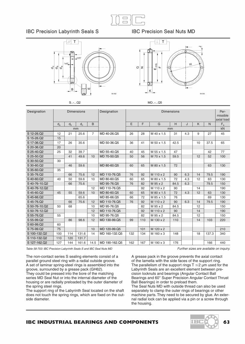
IBC INDUSTRIAL BEARINGS AND COMPONENTS 63
IBC Precision Labyrinth Seals S IBC Precision Seal Nuts MD
The non-contact series S sealing elements consist of aparallel ground steel ring with a radial outside groove.A set of laminar spring-steel rings is assembled into thegroove, surrounded by a grease pack (GH62).They could be pressed into the bore of the matchingseries MD Seal Nut or into the internal diameter of thehousing or are radially preloaded by the outer diameter ofthe spring steel rings.The support ring of the Labyrinth Seal located on the shaftdoes not touch the spring rings, which are fixed on the out-side diameter.
A grease pack in the groove prevents the axial contactof the lamella with the side faces of the support ring.The parallelism of the support rings T �2 µm used for theLabyrinth Seals are an excellent element between pre-cision locknuts and bearings (Angular Contact BallBearings and 60° Super Precision Angular Contact ThrustBall Bearings) in order to preload them.The Seal Nuts MD with outside thread can also be usedseparately to clamp the outer rings of bearings or othermachine parts. They need to be secured by glue. An exter-nal radial lock can be applied via a pin or a screw throughthe housing.
Designation Dimensions Designation Dimensions Per-missible
axial loadda db dc B E F G H J K N Fa
mm mm kN
S 12-26.Q2 12 21 25.6 7 MD 40-26.Q5 26 28 M 40 x 1.5 31 4.3 9 27 45S 15-26.Q2 15S 17-36.Q2 17 26 35.6 MD 50-36.Q5 36 41 M 50 x 1.5 42.5 10 37.5 65S 20-36.Q2 20S 25-40.Q2 25 32 39.7 MD 55-40.Q5 40 45 M 55 x 1.5 47 42 77S 25-50.Q2 41 49.6 10 MD 70-50.Q5 50 56 M 70 x 1.5 59.5 12 52 100S 30-50.Q2 30S 30-60.Q2 46 59.6 MD 80-60.Q5 60 65 M 80 x 1.5 72 63 130S 35-60.Q2 35S 35-76.Q2 66 75.6 12 MD 110-76.Q5 76 92 M 110 x 2 90 6.3 14 79.5 190S 40-60.Q2 40 50 59.6 10 MD 80-60.Q5 60 65 M 80 x 1.5 72 4.3 12 63 130S 40-76-10.Q2 66 75.6 MD 95-76.Q5 76 82 M 95 x 2 84.5 6.3 79.5 150S 40-76-12.Q2 12 MD 110-76.Q5 92 M 110 x 2 90 14 190S 45-60.Q2 45 55 59.6 10 MD 80-60.Q5 60 65 M 80 x 1.5 72 4.3 12 63 130S 45-66.Q2 65.6 MD 85-66.Q5 66 72 M 85 x 1.5 76 69 130S 45-76.Q2 66 75.6 12 MD 110-76.Q5 76 92 M 110 x 2 90 6.3 14 79.5 190S 50-76-10.Q2 50 68 10 MD 95-76.Q5 82 M 95 x 2 84.5 12 150S 50-76-12.Q2 12 MD 110-76.Q5 92 M 110 x 2 90 14 190S 55-76.Q2 55 10 MD 95-76.Q5 82 M 95 x 2 84.5 12 150S 55-99.Q2 86 98.6 12 MD 130-99.Q5 99 110 M 130 x 2 110 14 103 220S 60-99.Q2 60S 75-99.Q2 75 10 MD 120-99.Q5 101 M 120 x 2 210S 100-132.Q2 100 114 131.6 14 MD 160-132.Q5 132 134 M 160 x 3 148 18 137.3 340S 110-132.Q2 110 120 131.7S 127-162.Q2 127 144 161.6 14.5 MD 190-162.Q5 162 167 M 190 x 3 176 166 440
Table 58-703: IBC Precision Labyrinth Seals S and IBC Seal Nuts MD Further sizes are available on inquiry.

64 IBC WÄLZLAGER GMBH
11.3 Applications of IBC Precision Locknuts and Labyrinth Seals
58-001
58-802
58-803 58-804
44-801a

IBC INDUSTRIAL BEARINGS AND COMPONENTS 65
12. IBC Precision Bearings with ATCoat
Cross section of ATCoat
Coated bearings
The ATCoat enables a bearing to be higher resistantagainst corrosion, wear and allows an increase of speed.This is caused by thin dense chromium coat. The specialtopographic surface also increases the ability of a bearingto withstand emergency situations. All these abilities leadto use coated IBC bearings under uncomfortable lubrica-tion circumstances.
These conditions are for example as explained below:
– when it is impossible to use a lubricant.
– when it is only possible to use a low viscous lubricantwhich can not create a separating film.
– when the movement is not a complete rotation, wherethe lubricant film will not remain.
– when the bearing is unloaded and starts to slide.
– when the lubrication of the bearing is under the circum-stance that acceleration or braking bring the rolling ele-ments into slide.
The ATCoat coated bearings are an opportunity to corro-sion resistant bearings. It can compete especially withthose on the functional surfaces.The coating thickness is about 2–4 µm and the micro-scopical structure of the surface is ball headed. A combi-nation with ceramic balls lead to very good abilities underextreme conditions.
Purposes of ATCoat
Reduction of friction
Combination of static friction sliding frictionmaterials (dry) [µo] (dry) [µ]
Steel/Steel 0.25 0.18
Steel/ATCoat 0.17 0.15
ATCoat/ATCoat 0.14 0.12
– Better adhesion of lubricant film
– Separation of similar materials
– Reduction of friction welding caused by adhesion
– Reduction of fretting corrosion
– Saving of the sliding abilities from inner and outer ringagainst attached parts (floating bearings)
– Protection of the bearing against intruding corrosioncaused by aggressive materials (tribooxidation)
– Wear protection caused by higher hardness of the coat(78–80 HRC; 1300–1400 HV)
Prefixes of ATCoat bearingsAC- Inner and outer ring ATCoatedACC- Rolling elements Si3N4 + ATCoat
Suffixes of ATCoat coated bearingsA11 Inner and outer ring ATCoatedA15 Inner and outer ring ATCoated, rolling elements
and cage corrosion resistantA21, A26 Inner ring ATCoatedA31 Outer ring ATCoated
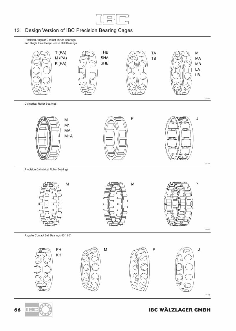
66 IBC WÄLZLAGER GMBH
13. Design Version of IBC Precision Bearing Cages
MM1MAM1A
Precision Angular Contact Thrust Bearingsand Single Row Deep Groove Ball Bearings
Cylindrical Roller Bearings
Precision Cylindrical Roller Bearings
Angular Contact Ball Bearings 40°; 60°
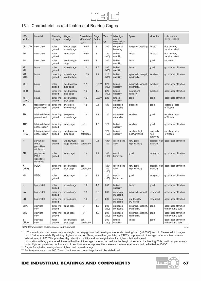
IBC INDUSTRIAL BEARINGS AND COMPONENTS 67
13.1 Characteristics and features of Bearing Cages
IBC Material Centring Cage Speed clas- Cage Temp.*** Misalign- Speed Vibration Lubricationsuffix of cage design sification* factor ment (always necessary)
dm · n nk °C (except sphericalroller bearing)
(J) JL/JN steel plate roller ribbon cage 0.65 1 300 danger of danger of breaking limited due to steel,guided riveted cage breaking very important
JH steel plate roller snap cage 0.65 1 220 limited limited limited due to steel,guided (300) usability very important
JW steel plate roller window type 0.65 1 300 limited limited good importantguided cage usability
M brass roller riveted cage 1.0 1.5 200 limited limited good good index of frictionM1 guided (300) usability
MA brass outer ring riveted cage 1.35 2.1 220 limited high mech. strength, excellent good index of frictionM1A guided window type (300) usability high inertia
MP brass roller solid window 1.1 0.75** 220 limited high mech. strength, excellent good index of frictionguided type cage (300) usability high inertia
MPB brass inner ring solid window 1.2 1.9 220 limited insufficient excellent good index of frictionguided type cage (300) usability flexibility
M brass outer ring solid window 1.3 0.85** 220 limited good good good index of friction(MPA) guided type cage usability
TA fabric-reinforced outer ring two-piece 1.5 2.4 120 not recom- excellent good excellent indexphenolic resin guided riveted cage mendable of friction
TB fabric-reinforced inner ring two-piece 1.4 2.2 120 not recom- excellent good excellent indexphenolic resin guided riveted cage mendable of friction
THB fabric-reinforced inner ring snap cage <1 1.5 120 limited excellent good good index of frictionphenolic resin guided usability
T fabric-reinforced outer ring solid window see 120 limited excellent high low inertia, excellent index(TPA) phenolic resin guided type cage catalogue (150) usability mech. strength well of friction
balanced
P polyamide roller window type see 2.1 120* recommend- very good, excellent high good index of frictionPA6.6 guided cage extruded catalogue 140* able high elasticity elasticityglass fibrereinforced
PH polyamide roller snap cage 1.4 2.1 140 elastic good very good good index of frictionPA6.6 guided (160) behaviourglass fibrereinforced
K PEEK outer ring solid window see 120* recommend- very good, excellent high good index of friction(KPA) guided type cage catalogue 140* able high elasticity elasticity
(160)
KH PEEK roller snap cage 1.4 2.1 120 elastic good very good good index of frictionguided (160) behaviour
L light metal roller riveted cage 1.2 1.9 200 limited limited good good index of frictionguided usability
LA light metal outer ring riveted cage 1.5 2.3 200 not recom- high mech. strength very good good index of frictionguided mendable
LB light metal inner ring riveted cage 1.3 2 200 not recom- low flexibility, very good good index of frictionguided mendable low inertia
SHA stainless outer ring snap cage <1 1.3 200 not recom- high mech. strength, good good index of frictionsteel guided (250) mendable high inertia with ceramic balls
SHB stainless inner ring snap cage <1 1.3 200 not recom- high mech. strength, good good index of frictionsteel guided (250) mendable high inertia with ceramic balls
S stainless roller solid window see 200 limited limited good good index of friction(SPA) steel guided type cage catalogue (250) usability with ceramic balls
* ·106 mm/min standard value only for single row deep groove ball bearing at moderate bearing load (<0.05 C) and oil. Please ask for cagesout of further materials. By adding of glass, or carbon fibres, as well as graphite, or PTFE components in the cage material a temperatureextension up to 260°C is possible. High stability, ductility and low weight allow for higher rotational speed.Lubrication with aggressive additives within the oil the cage material can reduce the length of service of a bearing. This could happen mainlyunder high temperature conditions and in such a case as a preventive measure the temperature should be limited to 100°C.
** Cages for spindle bearings have higher basic speed ratings.***For temperature above 140 °C also the inner and outer rings have to be stabalized.
Table: Characteristics and features of Bearing Cages 14-301

68 IBC WÄLZLAGER GMBH
14. Tolerances of associated parts for Precision Angular Contact Bearings
Accuracy of form for shafts Accuracy of form for housings
Characteristic Tolerance Tolerance Accuracy of form,Symbol Desig- Tolerance grade,
nation Roughness class forTolerance class of bearings
P6 P5 P4A P2A
Circularity t IT IT3 IT2 IT12 2 2 2
Cylindricity t1 IT IT3 IT2 IT12 2 2 2
Angularity t2 – – IT3 IT22 2
Runout t3 IT4 IT3 IT3 IT2
Coaxiality t4 IT6 IT5 IT4 IT3
Roughness Ra
d � 80 mm – N5 N4 N4 N3
d � 80 mm – N6 N5 N5 N4
Accuracy of form for shafts
ISO Basic Tolerance Grades acc. to DIN 7151Nominal Tolerance gradesDiameterOver incl. IT0 IT1 IT2 IT3 IT4 IT5 IT6 IT7mm µm
6 10 0.6 1 1.5 2.5 4 6 9 1510 18 0.8 1.2 2 3 5 8 11 2818 30 1 1.5 2.5 4 6 9 13 21
30 50 1 1.5 2.5 4 7 11 16 2550 80 1.2 2 3 5 8 13 19 3080 120 1.5 2.5 4 6 10 15 22 35
120 180 2 3.5 5 8 12 18 25 40180 250 3 4.5 7 10 14 20 29 46250 315 4 6 8 12 16 23 32 52
315 400 5 7 9 13 18 25 36 57400 500 6 8 10 15 20 27 40 63
Basic tolerance grades acc. to DIN 7151
Roughness Ra of the axial shoulder at shaft, housing orspacers:N6 = 0.8 µm
Characteristic Tolerance Tolerance Accuracy of form,Symbol Desig- Tolerance grade,
nation Roughness class forTolerance class of bearings
P6 P5 P4A P2A
Circularity t IT4 IT3 IT2 IT12 2 2 2
Cylindricity t1 IT4 IT3 IT2 IT12 2 2 2
Runout t3 IT4 IT3 IT3 IT2
Coaxiality t4 IT6 IT5 IT4 IT3
Roughness Ra
D � 80 mm – N6 N5 N5 N4
80 � D � 250 – N7 N6 N6 N5
D � 250 mm – N7 N7 N7 N6
Accuracy of form for housings
Surface roughness RoughnessClass
µm
N3 0.1N4 0.2N5 0.4N6 0.8N7 1.6
Roughness
40-306 40-308
40-309 40-310

IBC INDUSTRIAL BEARINGS AND COMPONENTS 69
15. Radial Clearance values in µm
Radial clearance of IBC deep groove ball bearings
Ø d [mm] over 2.5 6 10 18 24 30 40 50 65 80 100 120 140 160 180 200 225 250 280 315 335incl. 6 10 18 24 30 40 50 65 80 100 120 140 160 180 200 225 250 280 315 355 400
C2 min 0 0 0 0 1 1 1 1 1 1 2 2 2 2 2 4 4 4 8 8 8max 7 7 9 10 11 11 11 15 15 18 20 23 23 25 30 32 36 39 45 50 60
CN min 2 2 3 5 5 6 6 8 10 12 15 18 18 20 25 28 31 36 42 50 60max 13 13 18 20 20 20 23 28 30 36 41 48 53 61 71 82 92 97 110 120 140
C3 min 8 8 11 13 13 15 18 23 25 30 36 41 46 53 63 73 87 97 110 120 140max 23 23 25 28 28 33 36 43 51 58 66 81 91 102 117 132 152 162 180 200 230
C4 min 14 18 20 23 28 30 38 46 53 61 71 81 91 107 120 140 152 175 200 230max 29 33 36 41 46 51 61 71 84 97 114 130 147 163 187 217 237 260 290 330
C5 min 20 25 28 30 40 45 55 65 75 90 105 120 135 150 175 205 225 260 290 330max 37 45 48 53 64 73 90 105 120 140 160 180 200 230 255 290 320 360 405 460
Radial clearance of cylindrical roller bearings and needle roller bearings, single row and double row with cylindrical bore
Ø d [mm] over - 24 30 40 50 65 80 100 120 140 160 180 200 225 250 280 315 335 400 450 500incl. 24 30 40 50 65 80 100 120 140 160 180 200 225 250 280 315 355 400 450 500 560
C1 min 5 5 5 5 10 10 10 10 10 10 15 15 15 20 20 20 25 25 25 25max 15 15 18 20 25 30 30 35 35 40 45 50 50 55 60 65 75 85 95 105
SPC2X min 8 12 14 17 18 20 25 30 35 35 40 45 45 50 55 60 70 75 90 100max 23 25 30 35 38 40 45 50 65 70 75 85 100 110 120 130 145 165 185 205
C2 min 0 0 5 5 10 10 15 15 15 20 25 35 45 45 55 55 65 100 110 110 120max 25 25 30 35 40 45 50 55 60 70 75 90 105 110 125 130 145 190 210 220 240
CN min 20 20 25 30 40 40 50 50 60 70 75 90 105 110 125 130 145 190 210 220 240max 45 45 50 60 70 75 85 90 105 120 125 145 165 175 195 205 225 280 310 330 360
C3 min 35 35 45 50 60 65 75 85 100 115 120 140 160 170 190 200 225 280 310 330 360max 60 60 70 80 90 100 110 125 145 165 170 195 220 235 260 275 305 370 410 440 480
C4 min 50 50 60 70 80 90 105 125 145 165 170 195 220 235 260 275 305 370 410 440 480max 75 75 85 100 110 125 140 165 190 215 220 250 280 300 330 350 385 460 510 550 600
C5 min 75 75 85 100 110 125 140 165 190 215 220 250 280 300 330 350 385 460 510 550 600max 100 100 110 130 140 160 175 205 235 265 270 305 340 365 400 425 465 550 610 660 720
Radial clearance of cylindrical roller bearings and needle roller bearings, single row and double row with tapered bore
Table: Radial clearance
Ø d [mm] over - 24 30 40 50 65 80 100 120 140 160 180 200 225 250 280 315 335 400 450 500incl. 24 30 40 50 65 80 100 120 140 160 180 200 225 250 280 315 355 400 450 500 560
C1X min 5 5 5 5 10 10 10 10 10 10 15 15 15 20 20 20 25 25 25 25max 15 15 18 20 25 30 30 35 35 40 45 50 50 55 60 65 75 85 95 105
C1 min 15 15 17 20 25 35 40 45 50 55 60 60 65 75 80 90 100 110 120 130max 25 25 30 35 40 55 60 70 75 85 90 95 100 110 120 135 150 170 190 210
SPC2X min 15 16 18 20 25 33 40 45 50 55 60 65 70 75 80 90 100 110 120 130max 25 27 30 35 45 52 60 68 75 85 90 95 100 110 120 135 150 170 190 210
C2 min 15 20 20 25 30 35 40 50 55 60 75 85 95 105 115 130 145 165 185 205 230max 40 45 45 55 60 70 75 90 100 110 125 140 115 170 185 205 225 255 285 315 350
CN min 30 35 40 45 50 60 70 90 100 110 125 140 155 170 185 205 225 255 285 315 350max 55 60 65 75 80 95 105 130 145 160 175 195 215 235 255 280 305 345 385 425 470
C3 min 40 45 55 560 70 85 95 115 130 145 160 180 200 220 240 265 290 330 370 410 455max 65 70 80 90 100 120 130 155 175 195 210 235 260 285 310 340 370 420 470 520 575
C4 min 50 55 70 75 90 110 120 140 160 180 195 220 245 270 295 325 355 105 455 505 560max 75 80 95 105 120 145 155 180 205 230 245 275 305 335 365 400 435 495 555 615 680
C5 min 75 80 95 105 120 145 155 180 205 230 245 275 305 335 365 400 435 495 555 615 680max 100 105 120 135 150 180 190 20 250 280 295 330 365 400 435 475 515 585 655 725 800

70 IBC WÄLZLAGER GMBH
16. Tolerances of Radial Bearings
Inner ring [mm] Precision Ø 0.6 10 18 30 50 80 120 150 180 250to 10 18 30 50 80 120 150 180 250 315
∆dmp Max. deviation of the mean PN – 8 – 8 –10 –12 –15 –20 –25 –25 –30 –35bore diameter from the P6 – 7 – 7 – 8 –10 –12 –15 –18 –18 –22 –25nominal SP, P5 – 5 – 5 – 6 – 8 – 9 –10 –13 –13 –15 –18
P4 – 4 – 4 – 5 – 6 – 7 – 8 –10 –10 –12 –15P4A, P2H – 4 – 4 – 4 – 5 – 5 – 6 – 7.5 – 7.5 –10 –13P2A – 2.5 – 2.5 – 2.5 – 2.5 – 3.8 – 5.1 – 6.4 – 6.4 – 7.5 –
Kia Radial runout of assembled PN 10 10 13 15 20 25 30 30 40 50bearing inner ring P6 6 7 8 10 10 13 18 18 20 25
SP – – 3 4 4 5 6 6 8 –P5 4 4 4 5 5 6 8 8 10 13P4 2.5 2.5 3 4 4 5 6 6 8 –P4A 2.5 2.5 2.5 4 4 5 6 6 7.5 10P2H 2 2 2.5 2.5 2.5 2.5 2.5 2.5 5 5P2A 1.3 1.3 2.5 2.5 2.5 2.5 2.5 5 5 –
Sd Side face runout referring to SP, P5 7 7 8 8 8 9 10 10 11 13bore of inner ring P4 3 3 4 4 5 5 6 6 7 –
P4A 2 2 2 2 2 3 3 4 5 10P2H 1.5 1.5 1.7 1.8 2 2.5 2.5 4 5 6P2A 1.3 1.3 1.3 1.3 1.3 2.5 2.5 3.8 3.8 –
Sia Side face runout with SP, P5 7 7 8 8 8 9 10 10 15 15reference to the raceway of P4 3 3 4 4 5 5 7 7 8 –the assembled bearing P4A 2.5 2.5 4 4 4 5 7 7 7.5 10inner ring P2H 2 2 2.5 2.5 2.5 3.5 5 6 6.5 7
P2A 1.3 1.3 2.5 2.5 2.5 2.5 2.5 5 5 –
∆Bs Deviation of single inner ring PN, P6 –120 –120 –120 –120 –150 –200 –250 –250 –300 –350width SP, P5, P4 – 40 – 80 –100 –120 –150 –200 –250 –250 –300 –350
P4A, P2H, P2A –200 –200 –200 –200 –250 –320 –370 –370 –500 –
VBs Ring width variation PN, P6 15 20 20 20 25 25 30 30 30 35SP – – – 5 5 6 7 8 10 –P5 5 5 5 5 6 7 8 8 10 13P4 2.5 2.5 2.5 3 4 4 5 5 6 –P4A 2.5 2.5 2.5 2.5 4 4 5 5 5 8P2H 2 2 2 2 3 3 4 4 4 –P2A 1.3 1.3 1.3 1.3 1.3 2.5 2.5 4 4 –
Table: Tolerances of radial bearings
To simplify the arrangement of bearing sets and to ease upthe combination with assorted tolerances of shafts and hou-sings the grades for O.D. and bore are marked with the meandiameter variation of the reduced tolerance range. The meandeviation is approximately +/- 0.001 mm.
Example: 71907.E.T.P2H.X3.UL
D= 55.000 – 54.998 mm
d= 34.997 – 34.995 mm
The classification of the allowed tolerance into two or threeranges for the O.D. ∆Dm and bore ∆dm is done according tothe sizes of bore and the quality (P4A, P2H, P2A).Up to a total tolerance of 5 µm there are two ranges, a topand bottom which were marked with T and B are now markedwith numerical values of the mean tolerance range.Bigger size bearings with a total tolerance of more than 5 µmhave three ranges.There are resulting four respectively nine combinationsdenoted by the symbol X1 to X9.(See also matrix page 71.)As far as the graded combination is available it can bedelivered. But the bearings are not manufactured especiallyto a certain X_-category. A selection of this leads to priceincrease. (Additional information on demand.)
IBCDm: -1
dm: -4
Data table in µm
10-100
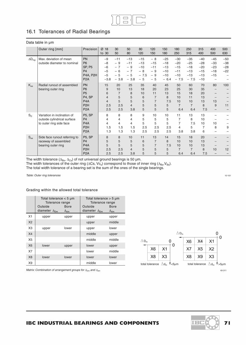
IBC INDUSTRIAL BEARINGS AND COMPONENTS 71
10-101
16.1 Tolerances of Radial Bearings
Grading within the allowed total tolerance
Total tolerance < 5 µm Total tolerance > 5 µmTolerance range Tolerance range
Outside Bore Outside Borediameter ∆Dm ∆dm diameter ∆Dm ∆dm
X1 upper upper upper upper
X2 upper middle
X3 upper lower upper lower
X4 middle upper
X5 middle middle
X6 lower upper lower upper
X7 lower middle
X8 lower lower lower lower
X9 middle lower
Matrix: Combination of arrangement groups for ∆Dm and ∆dm
Outer ring [mm] Precision Ø 18 30 50 80 120 150 180 250 315 400 500to 30 50 80 120 150 180 250 315 400 500 630
∆Dmp Max. deviation of mean PN –9 –11 –13 –15 – 8 –25 –30 –35 –40 –45 –50outside diameter to nominal P6 –8 – 9 –11 –13 –15 –18 –20 –25 –28 –33 –38
SP, P5 –6 – 7 – 9 –10 –11 –13 –15 –18 –20 –23 –28P4 –5 – 6 – 7 – 8 – 9 –10 –11 –13 –15 –18 –22P4A, P2H –5 – 5 – 5 – 7.5 – 9 –10 –10 –13 –13 –15 –P2A –3.8 – 3.8 – 3.8 – 5 – 5 – 6.4 – 7.5 – 7.5 –10 – –
Kea Radial runout of assembled PN 15 20 25 35 40 45 50 60 70 80 100bearing outer ring P6 9 10 13 18 20 23 25 30 35 – –
P5 6 7 8 10 11 13 15 18 20 – –P4, SP 4 5 5 6 7 8 10 11 13 – –P4A 4 5 5 5 7 7.5 10 10 13 13 –P2H 2.5 2.5 4 5 5 5 7 7 8 9 11P2A 2.5 2.5 3.8 5 5 5 6.4 6.4 7.5 – –
SD Variation in inclination of P5, SP 8 8 8 9 10 10 11 13 13 – –outside cylindrical surface P4 4 4 4 5 5 5 7 8 10 – –to outer ring side face P4A 4 4 4 5 5 5 7 7.5 10 10 –
P2H 1.5 1.5 1.5 2.5 2.5 2.5 4 5 7 8 9P2A 1.3 1.3 1.3 2.5 2.5 2.5 3.8 3.8 6 – –
Sea Side face runout referring to P5, SP 8 8 10 11 13 14 15 18 20 – –raceway of assembled P4 5 5 5 6 7 8 10 10 13 – –bearing outer ring P4A 5 5 5 5 7 7.5 10 10 13 – –
P2H 2.5 2.5 4 5 5 5 7 7 8 10 12P2A 2.5 2.5 3.8 5 5 5 6.4 6.4 7.5 – –
The width tolerance (∆Bs, ∆Cs) of not universal ground bearings is 50 µm.The width tolerances of the outer ring (∆Cs, Vcs) correspond to those of inner ring (∆Bs,VBs).The total width tolerance of a bearing set is the sum of the ones of the single bearings.
Table: Outer ring tolerances
Data table in µm
total tolerance total tolerance
Dm
Dm
dm <5µm >5µmdm
40-311

72 IBC WÄLZLAGER GMBH
16.2 Tolerances of Thrust Bearings
16.3 Axial Fixation of Bearing RingsOuter rings of bearings are most often clamped via flanges orretaining plates against a housing wall with socket head capscrews. Especially if bearings of a small cross section arebolted with a small number of screws an inadvertent one-sided fastening may result in an uneven deformation of theouter ring. This may lead to an inclination of the outer ring andresults into axial and/or radial runout. See examples.Tolerating the preload gap between retaining plate and hou-sing to 0.01 … 0.04 mm and the use of more smaller screwsthan some bigger ones will help. Fastening of the bolts shouldbe done in a controlled way step by step in a diagonalsequence instead of once with the final torque.
Precision Ø – 18 30 50 80 120 180Shaft washer to 18 30 50 80 120 180 250
∆dmp Mean bore diameter; arithmetical mean PN, P6, P5 – 8 –10 –12 –15 –20 –25 –30of the largest and smallest bore P4 – 7 – 8 –10 –12 – 5 –18 –22diameters measured in one plane
Vdp Bore diameter variation; difference PN, P6, P5 6 8 9 11 15 19 23between the largest and smallest single P4 5 6 8 9 11 14 17bore diameters in one radial plane
Si Shaft washer thickness variation from PN 10 10 10 10 15 15 20raceway middle to back face P6 5 5 6 7 8 9 10(axial runout of thrust bearings) P5 3 3 3 4 4 5 5
P4 2 2 2 3 3 4 4
Housing washer
∆Dmp Deviation of mean outside diameter from PN, P6, P5 –11 –13 –16 –19 –22 –25 –30nominal dimension P4 – 7 – 8 – 9 –11 –13 –15 –20
VDp Outside diameter variation; difference PN, P6, P5 8 10 12 14 17 19 23between the largest and smallest single P4 5 6 7 8 10 11 15outside diameters in one radial plane
Se Housing washer thickness variation P0 10 10 10 10 15 15 20from raceway middle to back face P6 5 5 6 7 8 9 10(axial runout of thrust bearings) P5 3 3 3 4 4 5 5
P4 2 2 2 3 3 4 4
Section height
∆Hs, Tmax Deviation of a single overall thrust 20 20 20 25 25 30Tmin bearing height from nominal dimension –250 –250 –300 –300 –400 –400
Table: Tolerances of thrust bearings
Axial fixation of bearing rings
Deformation of the raceway via retaining flange and screws
Adjust gap to the bearing width tolerances
3 screws 6 screws
afterbefore afterMeasurement
positionBs
tightening of screws
Fastening torque of screws [Nm]
Def
orm
atio
nof
race
way
diam
eter
[µm
]
10-200
10-102
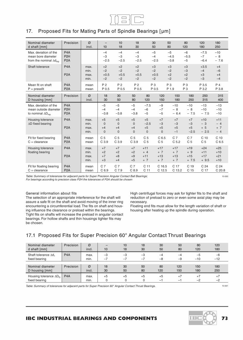
IBC INDUSTRIAL BEARINGS AND COMPONENTS 73
Table: Summary of tolerances for adjacent parts for Super Precision Angular Contact Ball Bearings;For bearings according to precision class P2H the tolerances of P2A should be chosen
Table: Summary of tolerances for adjacent parts for Super Precision 60° Angular Contact Thrust Bearings.
10-300
10-301
17. Proposed Fits for Mating Parts of Spindle Bearings [µm]
Nominal diameter Precision Ø – 10 18 30 50 80 120 180d shaft [mm] incl. 10 18 30 50 80 120 180 250
Max. deviation of the P4A –4 –4 –4 –5 –5 –6 –7.5 –10mean bore diameter P2H –3 –3 –3 –4 –4.5 –5.5 –7 – 8from the nominal ∆dmp P2A –2.5 –2.5 –2.5 –2.5 –3.8 –5 –6.4 – 7.6
Shaft tolerance P4A max. +2 +2 +2 +3 +3 +3 +3.5 +4min. –2 –2 –2 –2 –2 –3 –4 –6
P2A max. +0.5 +0.5 +0.5 +0.5 +2 +2 +3 +4min. –2 –2 –2 –2 –2 –2 –3 –4
Mean fit on shaft P4A mean P 2 P 2 P 2 P 3 P 3 P 3 P 3.5 P 4P = pressfit P2A mean P 0.5 P 0.5 P 0.5 P 0.5 P 1.9 P 3 P 3.2 P 3.8
Nominal diameter Precision Ø – 10 18 30 50 80 120d shaft [mm] incl. 10 18 30 50 80 120 180
Shaft tolerance ∆d1 P4A max. –3 –3 –3 –4 –4 –5 –6fixed bearing min. –7 –7 –7 –8 –9 –10 –12
Nominal diameter Precision Ø 18 30 50 80 120 150 180D housing [mm] incl. 30 50 80 120 150 180 250
Housing tolerance ∆DG P4A max. +5 +5 +5 +5 +7 +7 +7fixed bearing min. 0 0 0 –1 –1 –2 –2
Nominal diameter Precision Ø 18 30 50 80 120 150 180 250 315D housing [mm] incl. 30 50 80 120 150 180 250 315 400
Max. deviation of the P4A –5 –5 –5 –7.5 –9 –10 –10 –13 –13mean outside diameter P2H –4 –4 –4 –6 –7 – 8 – 8 –10 –10to nominal ∆Dmp P2A –3.8 –3.8 –3.8 –5 –5 – 6.4 – 7.5 – 7.5 –10
Housing tolerance P4A max. +5 +5 +5 +5 +7 +7 +7 +10 +11∆D fixed bearing min. 0 0 0 –2.5 –3 –3 –3 – 3 – 4
P2A max. +4 +4 +4 +5 +5 +5 +5 + 5 + 7min. 0 0 0 0 0 –1 –2.5 – 2.5 – 4
Fit for fixed bearing P4A mean C 5 C 5 C 5 C 5 C 6.5 C 7 C 7 C 10 C 10C = clearance P2A mean C 3.9 C 3.9 C 3.9 C 5 C 5 C 5.2 C 5 C 5 C 6.5
Housing tolerance P4A max. +7 +7 +7 +11 +17 +17 +19 +24 +25floating bearing min. +2 +2 +2 + 4 + 7 + 7 + 9 +11 +10
P2A max. +7 +8 +9 +11 +13 +13 +15 +17 +21min. +3 +4 +5 + 7 + 7 + 7 + 7.5 + 9.5 +10
Fit for floating bearing P4A mean C 7 C 7 C 7 C 11 C 16.5 C 17 C 19 C 24 C 24C = clearance P2A mean C 6.9 C 7.9 C 8.9 C 11 C 12.5 C 13.2 C 15 C 17 C 20.8
General information about fitsThe selection of an appropriate interference for the shaft willassure a safe fit on the shaft and avoid moving of the inner ringencountering a circumferential load. The fits on shaft and hous-ing influence the clearance or preload within the bearings.Tight fits on shafts will increase the preload in angular contactbearings. For hollow shafts and thin housings tighter fits maybe chosen.
17.1 Proposed Fits for Super Precision 60° Angular Contact Thrust Bearings
High centrifugal forces may ask for tighter fits to the shaft andreduction of preload to zero or even some axial play may benecessary.Floating end fits must allow for the length variation of shaft orhousing after heating up the spindle during operation.

74 IBC WÄLZLAGER GMBH
18. Lubrication of bearings – IBC BearLub-Greases
IBC Rotational Tempera- Consist- Basic oil Viscosity of Thickener Density Commentssuffix figures ture range ence clas- basic oil
sificationdm · n NLGI
·106 40°C 100°Cmm/min °C mm2/s g/cm3
GN 02 0.6 –30/+130 2 Mineral oil 100 10 Li-12 Hydro 0.9 Standard grease for single row deepStearat groove ball bearings until D=72,
noise reduced
GN 03 0.6 –25/+130 3 Mineral oil 100 10 Li-12 Hydro 0.9 Standard grease for single row deepStearat groove ball bearings above D=72,
noise reduced
GN 21 1.0 –35/+140 2 Mineral oil + 82 12.5 Li-12 Hydro 0.87 Multi purpose heavy duty grease forEP Stearat lubrication of guides and stationary
housing applications
GS 32 1.0 –50/+120 2 Mineral oil + 15 3.7 Li-soap 0.88 Noise tested grease for high rotationalEster oil speed and low temperatures
GS 34 1.0 –50/+120 2 Mineral oil + 21 4.7 Ba-Complex 0.99 High speed and low temperature greaseEster oil
GS 36 1.8 –40/+120 2/3 PAO Ester 25 6 Li-soap 0.94 Especially for high speed spindlebearings in machine tools
GS 41 1.0 –60/+140 2 SK- 18 4 Ba-Complex 0.96 High speed grease for taper rollerSynthetic oil soap bearings
GS 75 >2.0 –50/+120 2 Ester oil + 22 5 Polycarbamide 0.92 Especially for high speed spindleSKW bearings in machine tools
GH 62 0.5 –30/+160 2/3 Ester oil + 150 18 Polycarbamide 0.88 High temperature and long durationSKW
GH 68 1.3 –35/+160 2 Ester oil 55 9 Li-soap 0.975 Grease for high temperature,heavy duty and high speed
GH 70 0.6 –40/+180 2/3 Synthetic 70 9.4 Polycarbamide 0.95 Very low noise, high temperaturegrease
GH 72 0.7 –40/+180 2/3 Ester oil 100 12 Polycarbamide 0.97 Low noise, life time lubrication,high temperature, corrosion protective
GH 83 0.3 –60/+250 1 Fluoridated 300 85 PTFE 1.94 Highest viscosity during operation underPolyester oil high temperature conditions
GH 88 0.3 –30/+260 2 Perfluoro- 55 9 PU 1.7 High thermal and chemical resistance,polyether high performance under pressure,
radiation and in vacuum
GH 90 0.6 –50/+260 2 PFPE 190 34 PTFE 1.9 High life time, consistent with mostelastomers, good resistance againstaggressive chemicals
GA 91 0.3 –75/+260 1/2 Silicon oil Teflon Resistance against corrosion andoxidation, used for aircraft industry
GF 20 0.3 –40/+120 1 Mineral oil 230 22 Al-Complex 0.9 Good adhesive and wear protection,soap used for food industry
Table: Lubrication of bearings – IBC BearLub-Greases
The mentioned speed ratio (medium bearing diameter) of lubricants is a reference value for spring-preloaded bearings of medium diameter. Hybrid bearings allow for highervalues (35%), roller bearings and others allow for reduced values.
For further lubricants please ask our Technical Department.
14-300