timken fafnir super precision bearings for machine · pdf fileprice: usd $75 timken®...
TRANSCRIPT
Price: USD $75
TIMKEN® FAFNIR® SUPER PRECISION BEARINGS FOR MACHINE TOOL APPLICATIONS

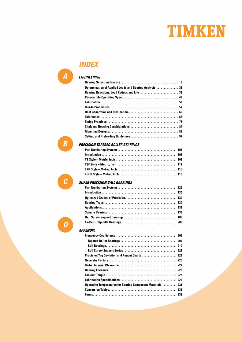
INDEX
ENGINEERING Bearing Selection Process . . . . . . . . . . . . . . . . . . . . . . . . . . . . . . . . . . . . . . . . . 9
Determination of Applied Loads and Bearing Analysis . . . . . . . . . . . . . . . 32 Bearing Reactions, Load Ratings and Life . . . . . . . . . . . . . . . . . . . . . . . . . . 38 Permissible Operating Speed . . . . . . . . . . . . . . . . . . . . . . . . . . . . . . . . . . . . . 49 Lubrication . . . . . . . . . . . . . . . . . . . . . . . . . . . . . . . . . . . . . . . . . . . . . . . . . . . . . . 52 Run-In Procedures . . . . . . . . . . . . . . . . . . . . . . . . . . . . . . . . . . . . . . . . . . . . . . . 57 Heat Generation and Dissipation . . . . . . . . . . . . . . . . . . . . . . . . . . . . . . . . . . . 60 Tolerances . . . . . . . . . . . . . . . . . . . . . . . . . . . . . . . . . . . . . . . . . . . . . . . . . . . . . . 63 Fitting Practices . . . . . . . . . . . . . . . . . . . . . . . . . . . . . . . . . . . . . . . . . . . . . . . . . 76 Shaft and Housing Considerations . . . . . . . . . . . . . . . . . . . . . . . . . . . . . . . . . 84 Mounting Designs . . . . . . . . . . . . . . . . . . . . . . . . . . . . . . . . . . . . . . . . . . . . . . . . 88 Setting and Preloading Guidelines . . . . . . . . . . . . . . . . . . . . . . . . . . . . . . . . . 97
PRECISION TAPERED ROLLER BEARINGS Part Numbering Systems . . . . . . . . . . . . . . . . . . . . . . . . . . . . . . . . . . . . . . . . . 103 Introduction . . . . . . . . . . . . . . . . . . . . . . . . . . . . . . . . . . . . . . . . . . . . . . . . . . . . 106 TS Style – Metric, Inch . . . . . . . . . . . . . . . . . . . . . . . . . . . . . . . . . . . . . . . . . . 108 TSF Style – Metric, Inch . . . . . . . . . . . . . . . . . . . . . . . . . . . . . . . . . . . . . . . . . 112 TXR Style – Metric, Inch . . . . . . . . . . . . . . . . . . . . . . . . . . . . . . . . . . . . . . . . . 116 TSHR Style – Metric, Inch . . . . . . . . . . . . . . . . . . . . . . . . . . . . . . . . . . . . . . . . 118
SUPER PRECISION BALL BEARINGS Part Numbering Systems . . . . . . . . . . . . . . . . . . . . . . . . . . . . . . . . . . . . . . . . . 125 Introduction . . . . . . . . . . . . . . . . . . . . . . . . . . . . . . . . . . . . . . . . . . . . . . . . . . . . 130
Optimized Grades of Precision . . . . . . . . . . . . . . . . . . . . . . . . . . . . . . . . . . . . 130 Bearing Types . . . . . . . . . . . . . . . . . . . . . . . . . . . . . . . . . . . . . . . . . . . . . . . . . . 130 Applications . . . . . . . . . . . . . . . . . . . . . . . . . . . . . . . . . . . . . . . . . . . . . . . . . . . . 133 Spindle Bearings . . . . . . . . . . . . . . . . . . . . . . . . . . . . . . . . . . . . . . . . . . . . . . . . 138 Ball Screw Support Bearings . . . . . . . . . . . . . . . . . . . . . . . . . . . . . . . . . . . . 188 Ex-Cell-O Spindle Bearings . . . . . . . . . . . . . . . . . . . . . . . . . . . . . . . . . . . . . . 202
APPENDIX Frequency Coefficients . . . . . . . . . . . . . . . . . . . . . . . . . . . . . . . . . . . . . . . . . . 206
Tapered Roller Bearings . . . . . . . . . . . . . . . . . . . . . . . . . . . . . . . . . . . . . . . 206 Ball Bearings . . . . . . . . . . . . . . . . . . . . . . . . . . . . . . . . . . . . . . . . . . . . . . . . . 210 Ball Screw Support Series . . . . . . . . . . . . . . . . . . . . . . . . . . . . . . . . . . . . . 222 Precision Tag Deviation and Runout Charts . . . . . . . . . . . . . . . . . . . . . . . . 223 Geometry Factors . . . . . . . . . . . . . . . . . . . . . . . . . . . . . . . . . . . . . . . . . . . . . . . 225 Radial Internal Clearance . . . . . . . . . . . . . . . . . . . . . . . . . . . . . . . . . . . . . . . . 227 Bearing Locknuts . . . . . . . . . . . . . . . . . . . . . . . . . . . . . . . . . . . . . . . . . . . . . . . 228 Locknut Torque . . . . . . . . . . . . . . . . . . . . . . . . . . . . . . . . . . . . . . . . . . . . . . . . . 228 Lubrication Specifications . . . . . . . . . . . . . . . . . . . . . . . . . . . . . . . . . . . . . . . 229 Operating Temperatures for Bearing Component Materials . . . . . . . . . . 231 Conversion Tables . . . . . . . . . . . . . . . . . . . . . . . . . . . . . . . . . . . . . . . . . . . . . . . 232 Forms . . . . . . . . . . . . . . . . . . . . . . . . . . . . . . . . . . . . . . . . . . . . . . . . . . . . . . . . . . 233
A
B
C
D
2
2
2
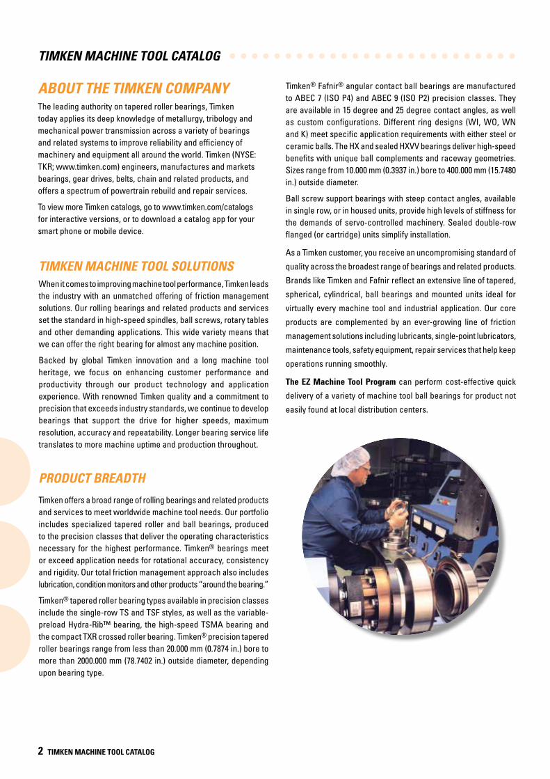
ABOUT THE TIMKEN COMPANYThe leading authority on tapered roller bearings, Timken today applies its deep knowledge of metallurgy, tribology and mechanical power transmission across a variety of bearings and related systems to improve reliability and efficiency of machinery and equipment all around the world. Timken (NYSE: TKR; www.timken.com) engineers, manufactures and markets bearings, gear drives, belts, chain and related products, and offers a spectrum of powertrain rebuild and repair services.
To view more Timken catalogs, go to www.timken.com/catalogs for interactive versions, or to download a catalog app for your smart phone or mobile device.
TIMKEN MACHINE TOOL CATALOG
2 TIMKEN MACHINE TOOL CATALOG
TIMKEN MACHINE TOOL SOLUTIONSWhen it comes to improving machine tool performance, Timken leads the industry with an unmatched offering of friction management solutions. Our rolling bearings and related products and services set the standard in high-speed spindles, ball screws, rotary tables and other demanding applications. This wide variety means that we can offer the right bearing for almost any machine position.
Backed by global Timken innovation and a long machine tool heritage, we focus on enhancing customer performance and productivity through our product technology and application experience. With renowned Timken quality and a commitment to precision that exceeds industry standards, we continue to develop bearings that support the drive for higher speeds, maximum resolution, accuracy and repeatability. Longer bearing service life translates to more machine uptime and production throughout.
PRODUCT BREADTH
Timken offers a broad range of rolling bearings and related products and services to meet worldwide machine tool needs. Our portfolio includes specialized tapered roller and ball bearings, produced to the precision classes that deliver the operating characteristics necessary for the highest performance. Timken® bearings meet or exceed application needs for rotational accuracy, consistency and rigidity. Our total friction management approach also includes lubrication, condition monitors and other products “around the bearing.”
Timken® tapered roller bearing types available in precision classes include the single-row TS and TSF styles, as well as the variable-preload Hydra-Rib™ bearing, the high-speed TSMA bearing and the compact TXR crossed roller bearing. Timken® precision tapered roller bearings range from less than 20.000 mm (0.7874 in.) bore to more than 2000.000 mm (78.7402 in.) outside diameter, depending upon bearing type.
Timken® Fafnir® angular contact ball bearings are manufactured to ABEC 7 (ISO P4) and ABEC 9 (ISO P2) precision classes. They are available in 15 degree and 25 degree contact angles, as well as custom configurations. Different ring designs (WI, WO, WN and K) meet specific application requirements with either steel or ceramic balls. The HX and sealed HXVV bearings deliver high-speed benefits with unique ball complements and raceway geometries. Sizes range from 10.000 mm (0.3937 in.) bore to 400.000 mm (15.7480 in.) outside diameter.
Ball screw support bearings with steep contact angles, available in single row, or in housed units, provide high levels of stiffness for the demands of servo-controlled machinery. Sealed double-row flanged (or cartridge) units simplify installation.
As a Timken customer, you receive an uncompromising standard of
quality across the broadest range of bearings and related products.
Brands like Timken and Fafnir reflect an extensive line of tapered,
spherical, cylindrical, ball bearings and mounted units ideal for
virtually every machine tool and industrial application. Our core
products are complemented by an ever-growing line of friction
management solutions including lubricants, single-point lubricators,
maintenance tools, safety equipment, repair services that help keep
operations running smoothly.
The EZ Machine Tool Program can perform cost-effective quick
delivery of a variety of machine tool ball bearings for product not
easily found at local distribution centers.
Introduction
TIMKEN MACHINE TOOL CATALOG 3
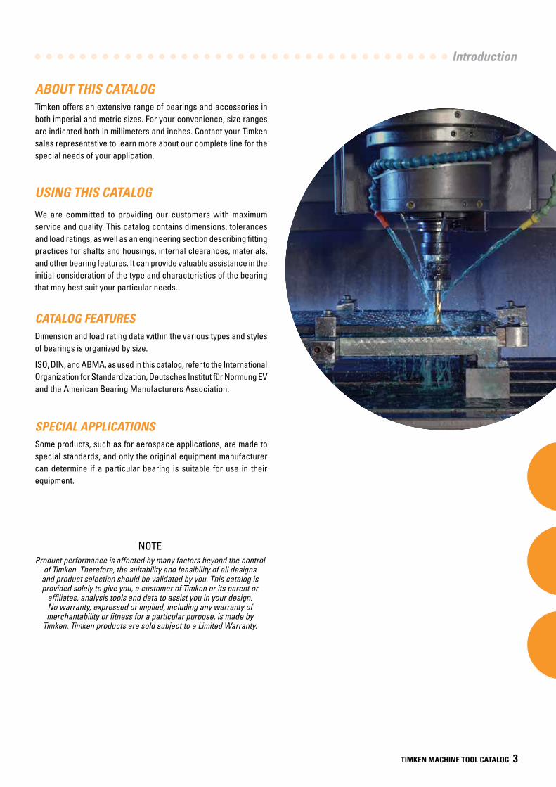
ABOUT THIS CATALOGTimken offers an extensive range of bearings and accessories in both imperial and metric sizes. For your convenience, size ranges are indicated both in millimeters and inches. Contact your Timken sales representative to learn more about our complete line for the special needs of your application.
USING THIS CATALOG
We are committed to providing our customers with maximum service and quality. This catalog contains dimensions, tolerances and load ratings, as well as an engineering section describing fitting practices for shafts and housings, internal clearances, materials, and other bearing features. It can provide valuable assistance in the initial consideration of the type and characteristics of the bearing that may best suit your particular needs.
CATALOG FEATURESDimension and load rating data within the various types and styles of bearings is organized by size.
ISO, DIN, and ABMA, as used in this catalog, refer to the International Organization for Standardization, Deutsches Institut für Normung EV and the American Bearing Manufacturers Association.
SPECIAL APPLICATIONSSome products, such as for aerospace applications, are made to special standards, and only the original equipment manufacturer can determine if a particular bearing is suitable for use in their equipment.
NOTEProduct performance is affected by many factors beyond the control
of Timken. Therefore, the suitability and feasibility of all designs and product selection should be validated by you. This catalog is provided solely to give you, a customer of Timken or its parent or
affiliates, analysis tools and data to assist you in your design. No warranty, expressed or implied, including any warranty of merchantability or fitness for a particular purpose, is made by
Timken. Timken products are sold subject to a Limited Warranty.
2
2
2
TIMKEN MACHINE TOOL CATALOG
4 TIMKEN MACHINE TOOL CATALOG
LIMITED WARRANTYWe warrant for a period of one year (unless a shorter period applies to a particular product) from the date of shipment that our products shall be free of defects in material and workmanship, as shall be determined by our manufacturing standards, and shall conform to the description on the face of our quotation or this acknowledgment. THE WARRANTY DESCRIBED HEREIN SHALL BE IN LIEU OF ANY OTHER WARRANTY, EXPRESS OR IMPLIED, INCLUDING BUT NOT LIMITED TO ANY IMPLIED WARRANTY OF MERCHANTABILITY OR FITNESS FOR A PARTICULAR PURPOSE. The terms contained herein constitute the entire agreement of the parties and the warranty representations of the seller. There are no other representations, warranties, or guarantees applicable to the sale of our products unless otherwise expressly agreed to by us in writing.
PURCHASER’S EXCLUSIVE REMEDY/SELLER’S EXPRESS LIMIT OF LIABILITY
Purchaser’s exclusive remedy for any warranty claim, or for any claim arising out of the purchase or use of our
products, shall be the replacement of said products. We will replace our products, without charge to the
purchaser, f.o.b. our point of shipment. We will not be liable for any consequential, incidental, or other damages sustained by purchaser, including but not limited to, loss of profits or revenue, loss of use of product, cost of capital, cost of substituted product, facilities, services, or claims of purchaser’s customers for any damages. Any warranty claim of purchaser
must be made within one year of the date of shipment of the product. This exclusive remedy
applies regardless of the nature of purchaser’s claim, whether in contract, tort, express or implied
warranty, negligence or strict liability, upon which damages are claimed and regardless of whether the
same is due to our negligence or any defect in our product.
TERMS AND CONDITIONS OF SALEAll products described in this catalog are sold subject to Timken’s Terms and Conditions of Sale.
It is understood that the buyer, in selecting and ordering from this catalog, which supersedes all previous editions, accepts all Terms and Conditions of Sale, a copy of which may be obtained from your Timken sales office. Timken objects to any additional or different terms.
WARNINGFailure to observe the following warnings could
create a risk of serious injury.
Proper maintenance and handling practices are critical. Always follow installation instructions and
maintain proper lubrication.
Never spin a bearing with compressed air. The rolling elements may be forcefully expelled.
NOTEEvery reasonable effort has been made to ensure the accuracy
of the information contained in this catalog, but no liability is accepted for errors, omissions or for any other reason.
Introduction
TIMKEN MACHINE TOOL CATALOG 5
SHELF LIFE AND STORAGE OF GREASE-LUBRICATED BEARINGS AND COMPONENTS
SHELF LIFEShelf life should be distinguished from lubricated bearing/component design life as follows:
Shelf life of the grease-lubricated bearing/component represents the period of time prior to use or installation.
The shelf life is a portion of the anticipated aggregate design life. It is impossible to accurately predict design life due to variations in lubricant bleed rates, oil migration, operating conditions, installation conditions, temperature, humidity and extended storage.
TIMKEN IS NOT RESPONSIBLE FOR THE SHELF LIFE OF ANY BEARING/COMPONENT LUBRICATED BY ANOTHER PARTY.
To help you get the most value from our products, Timken provides guidelines for the shelf life of grease-lubricated ball and roller bearings, components and assemblies. Shelf life information is based on Timken and industry test data and experience.
European REACH complianceTimken lubricants, greases and similar products sold in standalone containers or delivery systems are subject to the European REACH (Registration, Evaluation, Authorization and Restriction of CHemicals) directive. For import into the European Union, Timken can sell and provide only those lubricants and greases that are registered with ECHA (European CHemical Agency). For further information, please contact your Timken engineer.
STORAGETimken suggests the following storage guidelines for our finished products (bearings, components and assemblies, referred to as “products”):
• Unless directed otherwise by Timken, products should be kept in their original packaging until they are ready to be placed into service.
• Do not remove or alter any labels or stencil markings on the packaging.
• Products should be stored in such a way that the packaging is not pierced, crushed or otherwise damaged.
• After a product is removed from its packaging, it should be placed into service as soon as possible.
• When removing a product that is not individually packaged from a bulk pack container, the container should be resealed immediately after the product is removed.
• The storage area temperature should be maintained between 0° C (32° F) and 40° C (104° F); temperature fluctuations should be minimized.
• The relative humidity should be maintained below 60 percent and the surfaces should be dry.
• The storage area should be kept free from airborne contaminants such as, but not limited to, dust, dirt, harmful vapors, etc.
• The storage area should be isolated from undue vibration.
• Extreme conditions of any kind should be avoided.
Due to the fact that Timken is not familiar with your particular storage conditions, we strongly suggest following these guidelines. However, you may be required by circumstances or applicable government requirements to adhere to stricter storage requirements.
Most bearing components typically ship protected with a corrosion-preventive compound that is not a lubricant. These components may be used in oil-lubricated applications without removal of the corrosion-preventive compound. When using some specialized grease lubrications, we advise you to remove the corrosion-preventive compound before packing the bearing components with suitable grease.
Be careful in selecting lubrication, however, since different lubricants are often incompatible.
When you receive a bearing shipment, do not remove products from their packaging until they are ready for mounting so they do not become corroded or contaminated.
Store bearings and bearing housings in an appropriate atmosphere so they remain protected for the intended period.
2
2
2
TIMKEN MACHINE TOOL CATALOG
6 TIMKEN MACHINE TOOL CATALOG
AInasmuch as Timken is not familiar with a customer’s particular storage conditions, these guidelines are strongly suggested. However, the customer may very well be required by circumstance or applicable government requirements to adhere to stricter storage requirements.
Most bearing types are typically shipped protected with a corrosion- preventive compound that is not a lubricant. Such bearings may be used in oil-lubricated applications without removal of the corrosion-preventive compound. When using some specialized grease lubrication it is advisable to remove the corrosion-preventive compound before packing the bearings with suitable grease.
Some bearing types in this catalog are pre-packed with suggested grease suitable for their machine tool application. Frequent replenishment of the grease may be necessary for optimum performance. Care must be exercised in lubricant selection, however, since different lubricants are often incompatible.
When specified by the customer, bearings may be ordered pre-lubricated with suitable greases and oils.
Upon receipt of a bearing shipment, it should be ensured that the bearings are not removed from their packaging until they are ready for mounting so that they do not become corroded or contaminated. Bearings should be stored in an appropriate atmosphere in order that they remain protected for the intended period.
Any questions concerning the shelf life or storage policy should be directed to your local sales office.
Bearing Selection
ENGINEERING
A ENGINEERING
Bearing Selection Process . . . . . . . . . . . . . . . . . . . . . . . . . . . . . 9
Determination of Applied Loads and Bearing Analysis . . . . 32
Bearing Reactions, Load Ratings and Life . . . . . . . . . . . . . . . 38
Permissible Operating Speed . . . . . . . . . . . . . . . . . . . . . . . . . . 49
Lubrication . . . . . . . . . . . . . . . . . . . . . . . . . . . . . . . . . . . . . . . . . . 52
Run-In Procedures. . . . . . . . . . . . . . . . . . . . . . . . . . . . . . . . . . . . 57
Heat Generation and Dissipation . . . . . . . . . . . . . . . . . . . . . . . 60
Tolerances . . . . . . . . . . . . . . . . . . . . . . . . . . . . . . . . . . . . . . . . . . 63
Fitting Practices. . . . . . . . . . . . . . . . . . . . . . . . . . . . . . . . . . . . . . 76
Shaft and Housing Considerations . . . . . . . . . . . . . . . . . . . . . . 84
Mounting Designs . . . . . . . . . . . . . . . . . . . . . . . . . . . . . . . . . . . . 88
Setting and Preloading Guidelines . . . . . . . . . . . . . . . . . . . . . 97
AA

8 TIMKEN MACHINE TOOL CATALOG
AEN
GINEERINGA
8 TIMKEN MACHINE TOOL CATALOG
ENGINEERING
ATHE BEARING SELECTION PROCESS
TIMKEN® BEARINGS
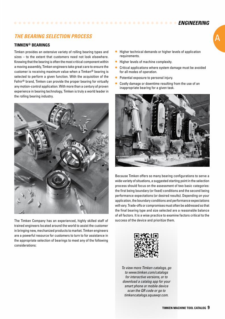
Timken provides an extensive variety of rolling bearing types and sizes – to the extent that customers need not look elsewhere. Knowing that the bearing is often the most critical component within a moving assembly, Timken engineers take great care to ensure the customer is receiving maximum value when a Timken® bearing is selected to perform a given function. With the acquisition of the Fafnir® brand, Timken can provide the proper bearing for virtually any motion-control application. With more than a century of proven experience in bearing technology, Timken is truly a world leader in the rolling bearing industry.
• Higher technical demands or higher levels of application requirements.
• Higher levels of machine complexity.
• Critical applications where system damage must be avoided for all modes of operation.
• Potential exposure to personal injury.
• Costly damage or downtime resulting from the use of an inappropriate bearing for a given task.
Because Timken offers so many bearing configurations to serve a wide variety of situations, a suggested starting point in the selection process should focus on the assessment of two basic categories: the first being boundary (or fixed) conditions and the second being performance expectations (or desired results). Depending on your application, the boundary conditions and performance expectations will vary. Trade-offs or compromises must often be addressed so that the final bearing type and size selected are a reasonable balance of all factors. It is a wise practice to examine factors critical to the success of the device and prioritize them. The Timken Company has an experienced, highly skilled staff of
trained engineers located around the world to assist the customer in bringing new, mechanized products to market. Timken engineers are a powerful resource for customers to turn to for assistance in the appropriate selection of bearings to meet any of the following considerations:A
To view more Timken catalogs, go to www.timken.com/catalogs for interactive versions, or to
download a catalog app for your smart phone or mobile device
scan the QR code or go to timkencatalogs.squawqr.com.
TIMKEN MACHINE TOOL CATALOG 9
ENGINEERING
A
10 TIMKEN MACHINE TOOL CATALOG
Boundary (or fixed) conditions that should be taken into consideration include:
• External loads, including radial, thrust, moment, shock and combination loads.
• Acceleration and deceleration levels.
• Operating temperature range (including extreme limits and thermal cycling).
• Other environmental factors, such as humidity, fluids, vibration, debris, magnetic fields.
• Spatial constraints.
Performance expectations (or desired results) to consider include:
• Rotational accuracy and repeatability (e.g., service precision level).
• System rigidity (axial or radial stiffness).
• Application service life.
• Speed.
Since the rolling bearing is an integral part of the machine, looking at the key operating parameters of the system also will help focus on the most viable bearing solution.
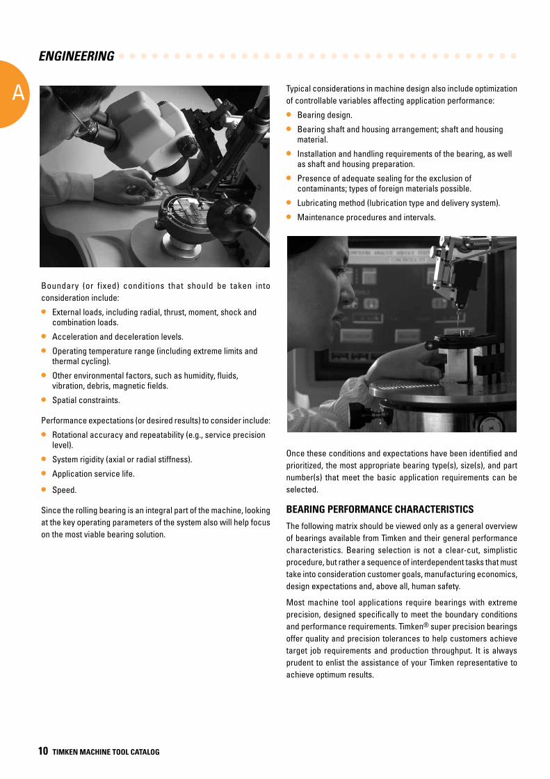
Typical considerations in machine design also include optimization of controllable variables affecting application performance:
• Bearing design.
• Bearing shaft and housing arrangement; shaft and housing material.
• Installation and handling requirements of the bearing, as well as shaft and housing preparation.
• Presence of adequate sealing for the exclusion of contaminants; types of foreign materials possible.
• Lubricating method (lubrication type and delivery system).
• Maintenance procedures and intervals.
Once these conditions and expectations have been identified and prioritized, the most appropriate bearing type(s), size(s), and part number(s) that meet the basic application requirements can be selected.
BEARING PERFORMANCE CHARACTERISTICS
The following matrix should be viewed only as a general overview of bearings available from Timken and their general performance characteristics. Bearing selection is not a clear-cut, simplistic procedure, but rather a sequence of interdependent tasks that must take into consideration customer goals, manufacturing economics, design expectations and, above all, human safety.
Most machine tool applications require bearings with extreme precision, designed specifically to meet the boundary conditions and performance requirements. Timken® super precision bearings offer quality and precision tolerances to help customers achieve target job requirements and production throughput. It is always prudent to enlist the assistance of your Timken representative to achieve optimum results.
ENGINEERING
A
TIMKEN MACHINE TOOL CATALOG 11
CharacteristicTapered roller
bearing Thrust tapered roller bearing
Cylindrical rollerbearing
Thrust cylindrical roller bearing
Spherical rollerbearing
Thrust sphericalroller bearing Ball bearing
Thrust ballbearing
Pure radial load Excellent Unsuitable Excellent Unsuitable Excellent Unsuitable Good Poor
Pure axial load Good Excellent Unsuitable Good Fair Excellent Fair Excellent
Combined load Excellent Fair Fair Unsuitable Excellent Fair Good Poor
Moment load Fair Poor Unsuitable Unsuitable Unsuitable Unsuitable Good Poor
High stiffness Excellent Excellent Good Excellent Good Good Good Good
Quiet running Fair Fair Good Poor Fair Poor Excellent Good
Low friction Good Fair Fair Poor Fair Fair Excellent Excellent
Misalignment Poor Poor Poor Unsuitable Excellent Excellent Good Poor
Locating position(fixed) Excellent Good Fair Fair Good Good Good Excellent
Non-locating position (floating) Good Unsuitable Excellent Unsuitable Fair Unsuitable Good Unsuitable
Speed Good Fair Good Poor Fair Poor Excellent Fair
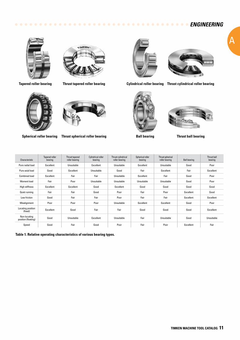
Table 1. Relative operating characteristics of various bearing types.
Cylindrical roller bearingTapered roller bearing
Spherical roller bearing Ball bearingThrust spherical roller bearing
Thrust tapered roller bearing Thrust cylindrical roller bearing
Thrust ball bearing
ENGINEERING
A
12 TIMKEN MACHINE TOOL CATALOG
Timken offers a wide range of products targeted for improving machining efficiency, cutting accuracy, and productivity. Qualified sales and service engineers are available to help determine an appropriate solution for individual applications.
TIMKEN® SUPER PRECISION BEARINGSManufacturers require machine tools that are extremely accurate, reliable and capable of high levels of productivity. A major contribution to the performance of any machine tool is supplied by the rolling bearings used to support the spindles, rotating tables, ball screws and other critical precision positions. A manufactured bearing’s precision level has a major influence on the ability to perform in high-speed applications commonly seen in factory machining environments.
WHICH TYPE OF TIMKEN BEARING IS MOST APPROPRIATE FOR YOUR MACHINE TOOL APPLICATION?
To achieve the highest possible performance precision level, the majority of machine tool-related bearing applications must address four primary requirements: speed, stiffness, accuracy and load capacity.
Speed
Today’s industrial machining environments stress maximum production rates. To reach these high metal-removal goals, machines are operating at maximum speeds with working spindles tuned to provide premium running accuracy.
Achievable spindle rotating speeds require management of heat generation within the bearing assembly. The bearing’s ability to not only minimize heat buildup, but also expel excess heat, is a crucial consideration in the bearing selection process. Because of the differences in rolling element contact geometry, ball bearings are superior in minimizing heat generation, especially where higher speeds are desired.
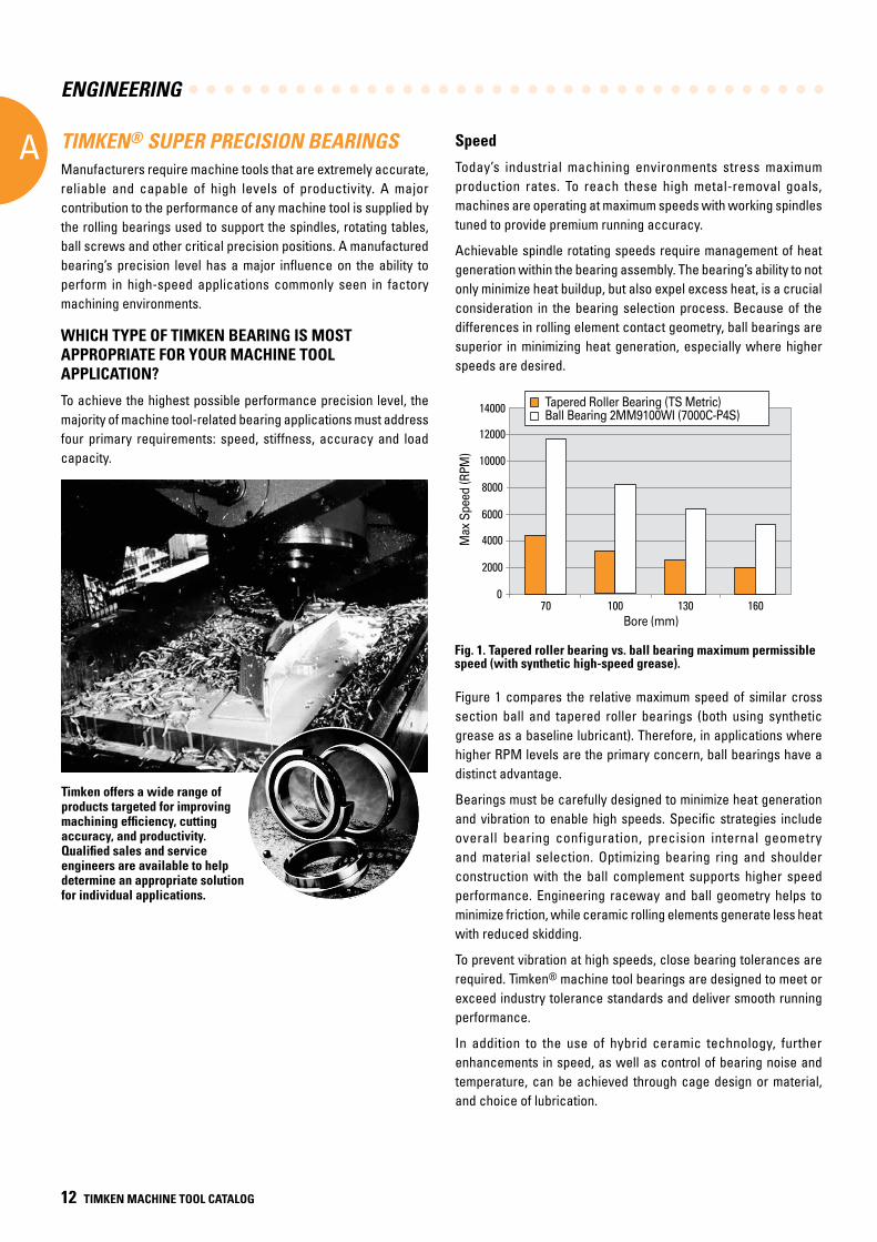
Figure 1 compares the relative maximum speed of similar cross section ball and tapered roller bearings (both using synthetic grease as a baseline lubricant). Therefore, in applications where higher RPM levels are the primary concern, ball bearings have a distinct advantage.
Bearings must be carefully designed to minimize heat generation and vibration to enable high speeds. Specific strategies include overall bearing configuration, precision internal geometry and material selection. Optimizing bearing ring and shoulder construction with the ball complement supports higher speed performance. Engineering raceway and ball geometry helps to minimize friction, while ceramic rolling elements generate less heat with reduced skidding.
To prevent vibration at high speeds, close bearing tolerances are required. Timken® machine tool bearings are designed to meet or exceed industry tolerance standards and deliver smooth running performance.
In addition to the use of hybrid ceramic technology, further enhancements in speed, as well as control of bearing noise and temperature, can be achieved through cage design or material, and choice of lubrication.
Fig. 1. Tapered roller bearing vs. ball bearing maximum permissible speed (with synthetic high-speed grease).
14000
Max
Spe
ed (R
PM)
12000
10000
8000
4000
6000
2000
070 100 130 160
Bore (mm)
Sprin
g Ra
te R
atio
Tapered Roller Bearing
Cylindrical Roller Bearing
Angular Contact Ball Bearing
Radial Load on the Bearing(relative to tapered roller bearing radial rating)
7
0 50% 100%0
1
2
3
4
5
6
8
Ball Bearing (2MM9100WI)Tapered Roller Bearing (TS Metric)Tapered Roller Bearing (TS Metric)Ball Bearing 2MM9100WI (7000C-P4S)
Max
Spe
ed (R
PM)
Bore (mm)
ENGINEERING
A
TIMKEN MACHINE TOOL CATALOG 13
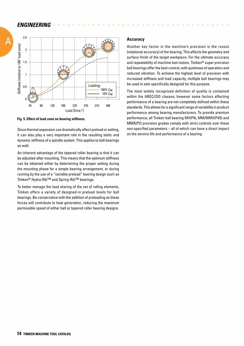
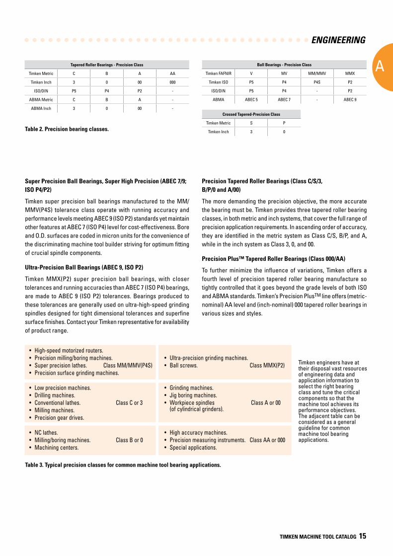
Stiffness
The ability to minimize tool deflection experienced under cutting loads is vital to achieving the accuracy needed to produce finished parts within specified tolerances. Less variance produces better quality and helps keep product scrap levels at a minimum. Bearings have a significant effect on spindle stiffness, due to their deflection under applied load. Because of their internal geometry and rolling element type, tapered roller bearings provide considerably higher stiffness levels as shown in Figure 3 and 4.
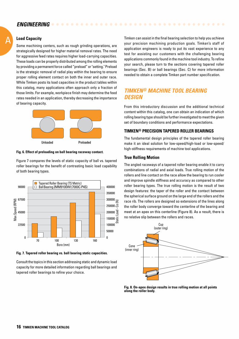
Bearing stiffness also depends on design load zone, which is directly related to bearing setting, clearances and applied loads. (Setting is defined as a specific amount of either end play or preload.)(1) A bearing under radial load with zero end play/zero preload has a load zone close to 180 degrees, while a bearing with preload can reach 360 degrees load zone. Figure 5 shows the effect of load zone on tapered roller bearing stiffness. The curves demonstrate that while the effect of external loads on stiffness is important, the impact from setting is more significant.
Fig. 3. Tapered roller bearing vs. ball bearing radial stiffness.
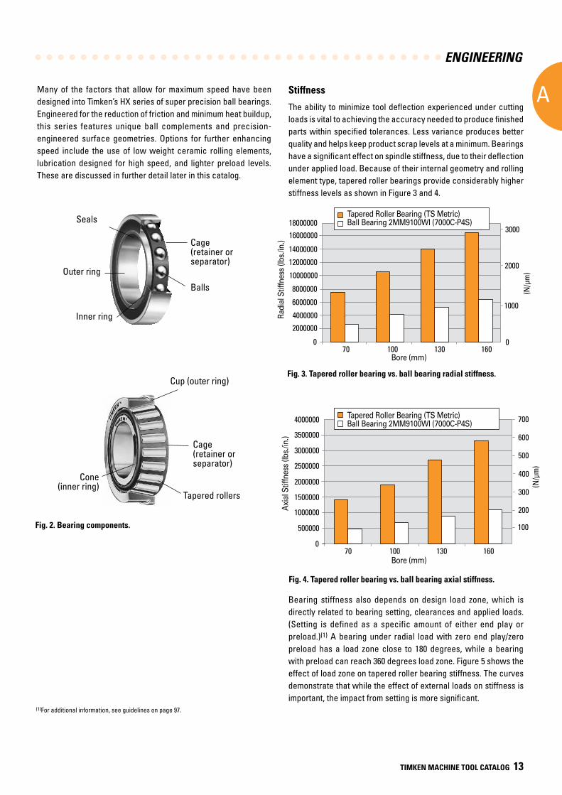
Seals
Outer ring
Cage(retainer or separator)
Balls
Inner ring
Cup (outer ring)
Cage(retainer or separator)
Tapered rollers
Cone (inner ring)
Many of the factors that allow for maximum speed have been designed into Timken’s HX series of super precision ball bearings. Engineered for the reduction of friction and minimum heat buildup, this series features unique ball complements and precision-engineered surface geometries. Options for further enhancing speed include the use of low weight ceramic rolling elements, lubrication designed for high speed, and lighter preload levels. These are discussed in further detail later in this catalog.
(1)For additional information, see guidelines on page 97.
Fig. 2. Bearing components.
Fig. 4. Tapered roller bearing vs. ball bearing axial stiffness.
4000000
Axia
l Stif
fnes
s (lb
s./in
.)
3500000
3000000
2500000
2000000
1000000
1500000
500000
070 100 130 160
Bore (mm)
100(N
/µm
)
200
300
400
500
600
700
18000000 Ball Bearing (2MM9100WI)Tapered Roller Bearing (TS Metric)
Ball Bearing (2MM9100WI)Tapered Roller Bearing (TS Metric)
Radi
al S
tiffn
ess
(lbs.
/in.)
16000000
14000000
12000000
10000000
6000000
8000000
4000000
070 100 130 160
Bore (mm)
0
(N/µ
m)
1000
2000
3000
2000000
Tapered Roller Bearing (TS Metric)Ball Bearing 2MM9100WI (7000C-P4S)
Tapered Roller Bearing (TS Metric)Ball Bearing 2MM9100WI (7000C-P4S)
Radi
al S
tiffn
ess
(lbs.
/in.)
Axia
l Stif
fnes
s (lb
s./in
.)
Bore (mm)
Bore (mm)
ENGINEERING
A
14 TIMKEN MACHINE TOOL CATALOG
Since thermal expansion can dramatically affect preload or setting, it can also play a very important role in the resulting static and dynamic stiffness of a spindle system. This applies to ball bearings as well.
An inherent advantage of the tapered roller bearing is that it can be adjusted after mounting. This means that the optimum stiffness can be obtained either by determining the proper setting during the mounting phase for a simple bearing arrangement, or during running by the use of a “variable preload” bearing design such as Timken® Hydra-RibTM and Spring-RibTM bearings.
To better manage the load sharing of the set of rolling elements, Timken offers a variety of designed-in preload levels for ball bearings. Be conservative with the addition of preloading as these forces will contribute to heat generation, reducing the maximum permissible speed of either ball or tapered roller bearing designs.
Accuracy
Another key factor in the machine’s precision is the runout (rotational accuracy) of the bearing. This affects the geometry and surface finish of the target workpiece. For the ultimate accuracy and repeatability of machine tool motion, Timken® super precision ball bearings offer the best control, with quietness of operation and reduced vibration. To achieve the highest level of precision with increased stiffness and load capacity, multiple ball bearings may be used in sets specifically designed for this purpose.
The most widely recognized definition of quality is contained within the ABEC/ISO classes; however some factors affecting performance of a bearing are not completely defined within these standards. This allows for a significant range of variability in product performance among bearing manufacturers. To provide premium performance, all Timken ball bearing MV(P4), MM/MMV(P4S) and MMX(P2) precision grades comply with strict controls over these non-specified parameters – all of which can have a direct impact on the service life and performance of a bearing.
Fig. 5. Effect of load zone on bearing stiffness.
Stiff
ness
(rel
ativ
e to
180
˚ loa
d zo
ne)
135Load Zone (˚)
Loading:100% C90
10% C90
18045 90 225 270 315 360
0
0.5
1.5
2.5
2
1
Stiff
ness
(rel
ativ
e to
180
˚ loa
d zo
ne)
Load Zone (˚)
Loading:
ENGINEERING
A
TIMKEN MACHINE TOOL CATALOG 15
Tapered Roller Bearings - Precision Class
Timken Metric C B A AA
Timken Inch 3 0 00 000
ISO/DIN P5 P4 P2 -
ABMA Metric C B A -
ABMA Inch 3 0 00 -
Ball Bearings - Precision Class
Timken FAFNIR V MV MM/MMV MMX
Timken ISO P5 P4 P4S P2
ISO/DIN P5 P4 - P2
ABMA ABEC 5 ABEC 7 - ABEC 9
Crossed Tapered-Precision Class
Timken Metric S P
Timken Inch 3 0Table 2. Precision bearing classes.
Super Precision Ball Bearings, Super High Precision (ABEC 7/9; ISO P4/P2)
Timken super precision ball bearings manufactured to the MM/MMV(P4S) tolerance class operate with running accuracy and performance levels meeting ABEC 9 (ISO P2) standards yet maintain other features at ABEC 7 (ISO P4) level for cost-effectiveness. Bore and O.D. surfaces are coded in micron units for the convenience of the discriminating machine tool builder striving for optimum fitting of crucial spindle components.
Ultra-Precision Ball Bearings (ABEC 9, ISO P2)
Timken MMX(P2) super precision ball bearings, with closer tolerances and running accuracies than ABEC 7 (ISO P4) bearings, are made to ABEC 9 (ISO P2) tolerances. Bearings produced to these tolerances are generally used on ultra-high-speed grinding spindles designed for tight dimensional tolerances and superfine surface finishes. Contact your Timken representative for availability of product range.
Precision Tapered Roller Bearings (Class C/S/3, B/P/0 and A/00)
The more demanding the precision objective, the more accurate the bearing must be. Timken provides three tapered roller bearing classes, in both metric and inch systems, that cover the full range of precision application requirements. In ascending order of accuracy, they are identified in the metric system as Class C/S, B/P, and A, while in the inch system as Class 3, 0, and 00.
Precision Plus™ Tapered Roller Bearings (Class 000/AA)
To further minimize the influence of variations, Timken offers a fourth level of precision tapered roller bearing manufacture so tightly controlled that it goes beyond the grade levels of both ISO and ABMA standards. Timken’s Precision PlusTM line offers (metric-nominal) AA level and (inch-nominal) 000 tapered roller bearings in various sizes and styles.
• High-speed motorized routers.• Precision milling/boring machines.• Super precision lathes. Class MM/MMV(P4S)• Precision surface grinding machines.
• Low precision machines.• Drilling machines.• Conventional lathes. Class C or 3 • Milling machines.• Precision gear drives.
• NC lathes.• Milling/boring machines. Class B or 0 • Machining centers.
• Ultra-precision grinding machines.• Ball screws. Class MMX(P2)
• Grinding machines.• Jig boring machines.• Workpiece spindles Class A or 00 (of cylindrical grinders).
• High accuracy machines.• Precision measuring instruments. Class AA or 000 • Special applications.
Table 3. Typical precision classes for common machine tool bearing applications.
Timken engineers have at their disposal vast resources of engineering data and application information to select the right bearing class and tune the critical components so that the machine tool achieves its performance objectives. The adjacent table can be considered as a general guideline for common machine tool bearing applications.
ENGINEERING
A
16 TIMKEN MACHINE TOOL CATALOG
Timken can assist in the final bearing selection to help you achieve your precision machining production goals. Timken’s staff of application engineers is ready to put its vast experience to any test for assisting our customers with the challenging bearing applications commonly found in the machine tool industry. To refine your search, please turn to the sections covering tapered roller bearings (Sec. B) or ball bearings (Sec. C) for more information needed to obtain a complete Timken part number specification.
TIMKEN® MACHINE TOOL BEARING DESIGN
From this introductory discussion and the additional technical content within this catalog, one can obtain an indication of which rolling bearing type should be further investigated to meet the given set of boundary conditions and performance expectations.
TIMKEN® PRECISION TAPERED ROLLER BEARINGS
The fundamental design principles of the tapered roller bearing make it an ideal solution for low-speed/high-load or low-speed/high-stiffness requirements of machine tool applications.
True Rolling Motion
The angled raceways of a tapered roller bearing enable it to carry combinations of radial and axial loads. True rolling motion of the rollers and line contact on the race allow the bearing to run cooler and improve spindle stiffness and accuracy as compared to other roller bearing types. The true rolling motion is the result of two design features: the taper of the roller and the contact between the spherical surface ground on the large end of the rollers and the race rib. The rollers are designed so extensions of the lines along the roller body converge toward the centerline of the bearing and meet at an apex on this centerline (Figure 8). As a result, there is no relative slip between the rollers and races.
Fig. 8. On-apex design results in true rolling motion at all points along the roller body.
Load Capacity
Some machining centers, such as rough grinding operations, are strategically designed for higher material removal rates. The need for aggressive feed rates requires higher load-carrying capacities. These loads can be properly distributed among the rolling elements by providing a permanent force called “preload” or "setting." Preload is the strategic removal of radial play within the bearing to ensure proper rolling element contact on both the inner and outer race. While Timken posts its load capacities in the product tables within this catalog, many applications often approach only a fraction of those limits. For example, workpiece finish may determine the feed rates needed in an application, thereby decreasing the importance of bearing capacity.
Fig. 6. Effect of preloading on ball bearing raceway contact.
Figure 7 compares the levels of static capacity of ball vs. tapered roller bearings for the benefit of contrasting basic load capability of both bearing types.
Fig. 7. Tapered roller bearing vs. ball bearing static capacities.
Consult the topics in this section addressing static and dynamic load capacity for more detailed information regarding ball bearings and tapered roller bearings to refine your choice.
UnloadedUnloaded PreloadedPreloadedUnloaded Preloaded
Cup(outer ring)
Cone(inner ring)
Cup (outer ring)
Cone (inner ring)
90000 Ball Bearing (2MM9100WI)Tapered Roller Bearing (TS Metric)
Stat
ic L
oad
- Co
(lbs.
)
67500
45000
22500
0
400000
Stat
ic L
oad
- Co
(N)
350000
300000
250000
200000
100000
150000
50000
070 100 130 160
Bore (mm)
Tapered Roller Bearing (TS Metric)Ball Bearing 2MM9100WI (7000C-P4S)
Bore (mm)
Max
Spe
ed (R
PM)
Stat
ic Lo
ad -
Co (N
)
ENGINEERING
A
TIMKEN MACHINE TOOL CATALOG 17
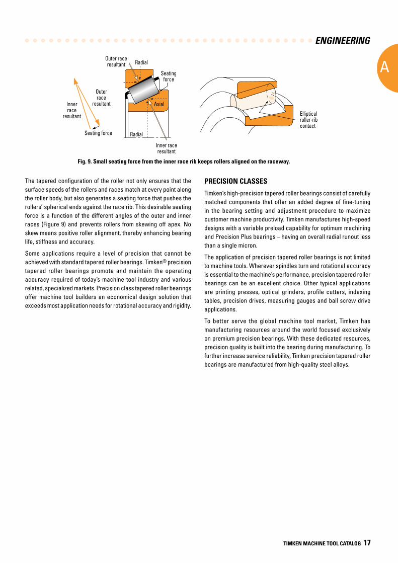
Fig. 9. Small seating force from the inner race rib keeps rollers aligned on the raceway.
Elliptical roller-rib contact
Inner race resultant
Innerrace
resultant
Outerrace
resultant
Seating force Radial
Seating forceAxial
RadialOuter race resultant
AxialElliptical roller-rib contact
Inner race resultant
Innerrace
resultant
Outerrace
resultant
Seating force Radial
Seating forceAxial
RadialOuter race resultant
Axial
The tapered configuration of the roller not only ensures that the surface speeds of the rollers and races match at every point along the roller body, but also generates a seating force that pushes the rollers’ spherical ends against the race rib. This desirable seating force is a function of the different angles of the outer and inner races (Figure 9) and prevents rollers from skewing off apex. No skew means positive roller alignment, thereby enhancing bearing life, stiffness and accuracy.
Some applications require a level of precision that cannot be achieved with standard tapered roller bearings. Timken® precision tapered roller bearings promote and maintain the operating accuracy required of today’s machine tool industry and various related, specialized markets. Precision class tapered roller bearings offer machine tool builders an economical design solution that exceeds most application needs for rotational accuracy and rigidity.
PRECISION CLASSES
Timken’s high-precision tapered roller bearings consist of carefully matched components that offer an added degree of fine-tuning in the bearing setting and adjustment procedure to maximize customer machine productivity. Timken manufactures high-speed designs with a variable preload capability for optimum machining and Precision Plus bearings – having an overall radial runout less than a single micron.
The application of precision tapered roller bearings is not limited to machine tools. Wherever spindles turn and rotational accuracy is essential to the machine’s performance, precision tapered roller bearings can be an excellent choice. Other typical applications are printing presses, optical grinders, profile cutters, indexing tables, precision drives, measuring gauges and ball screw drive applications.
To better serve the global machine tool market, Timken has manufacturing resources around the world focused exclusively on premium precision bearings. With these dedicated resources, precision quality is built into the bearing during manufacturing. To further increase service reliability, Timken precision tapered roller bearings are manufactured from high-quality steel alloys.
Inner race
resultant
Outer race
resultant
Seating force
Seating force
Radial
Radial
Axial
Outer race resultant
Inner race resultant
Elliptical roller-rib contact
ENGINEERING
A
18 TIMKEN MACHINE TOOL CATALOG
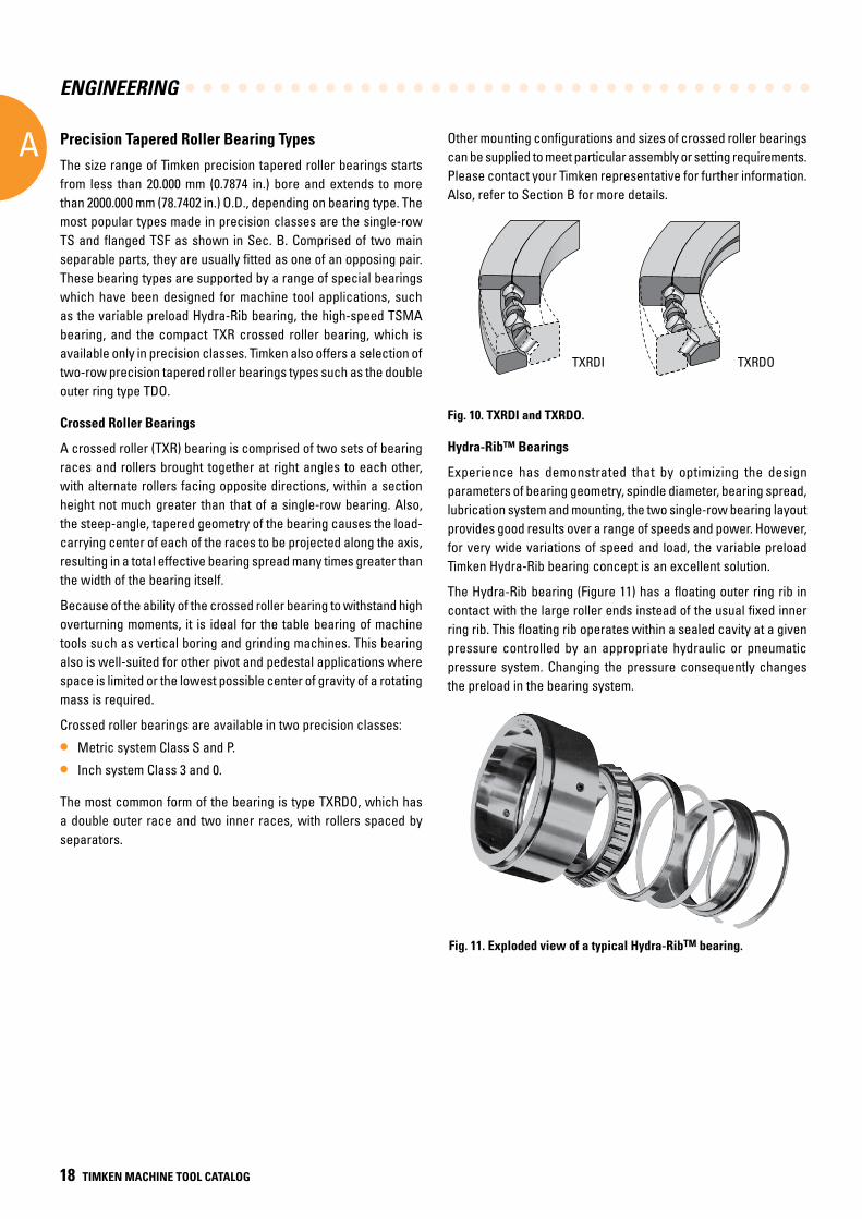
Other mounting configurations and sizes of crossed roller bearings can be supplied to meet particular assembly or setting requirements. Please contact your Timken representative for further information. Also, refer to Section B for more details.
Fig. 10. TXRDI and TXRDO.
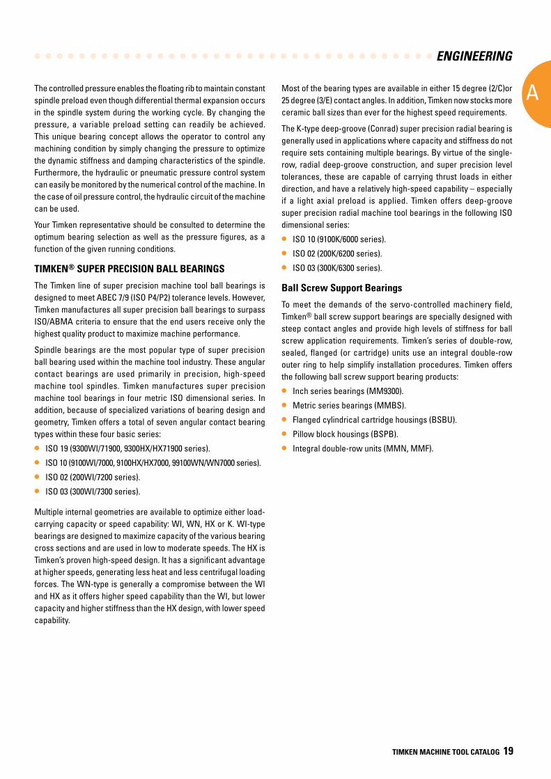
Hydra-Rib™ Bearings
Experience has demonstrated that by optimizing the design parameters of bearing geometry, spindle diameter, bearing spread, lubrication system and mounting, the two single-row bearing layout provides good results over a range of speeds and power. However, for very wide variations of speed and load, the variable preload Timken Hydra-Rib bearing concept is an excellent solution.
The Hydra-Rib bearing (Figure 11) has a floating outer ring rib in contact with the large roller ends instead of the usual fixed inner ring rib. This floating rib operates within a sealed cavity at a given pressure controlled by an appropriate hydraulic or pneumatic pressure system. Changing the pressure consequently changes the preload in the bearing system.
Fig. 11. Exploded view of a typical Hydra-RibTM bearing.
Precision Tapered Roller Bearing Types
The size range of Timken precision tapered roller bearings starts from less than 20.000 mm (0.7874 in.) bore and extends to more than 2000.000 mm (78.7402 in.) O.D., depending on bearing type. The most popular types made in precision classes are the single-row TS and flanged TSF as shown in Sec. B. Comprised of two main separable parts, they are usually fitted as one of an opposing pair. These bearing types are supported by a range of special bearings which have been designed for machine tool applications, such as the variable preload Hydra-Rib bearing, the high-speed TSMA bearing, and the compact TXR crossed roller bearing, which is available only in precision classes. Timken also offers a selection of two-row precision tapered roller bearings types such as the double outer ring type TDO.
Crossed Roller Bearings
A crossed roller (TXR) bearing is comprised of two sets of bearing races and rollers brought together at right angles to each other, with alternate rollers facing opposite directions, within a section height not much greater than that of a single-row bearing. Also, the steep-angle, tapered geometry of the bearing causes the load-carrying center of each of the races to be projected along the axis, resulting in a total effective bearing spread many times greater than the width of the bearing itself.
Because of the ability of the crossed roller bearing to withstand high overturning moments, it is ideal for the table bearing of machine tools such as vertical boring and grinding machines. This bearing also is well-suited for other pivot and pedestal applications where space is limited or the lowest possible center of gravity of a rotating mass is required.
Crossed roller bearings are available in two precision classes:
• Metric system Class S and P.
• Inch system Class 3 and 0.
The most common form of the bearing is type TXRDO, which has a double outer race and two inner races, with rollers spaced by separators.
TXRDOTXRDI
ENGINEERING
A
TIMKEN MACHINE TOOL CATALOG 19
The controlled pressure enables the floating rib to maintain constant spindle preload even though differential thermal expansion occurs in the spindle system during the working cycle. By changing the pressure, a variable preload setting can readily be achieved. This unique bearing concept allows the operator to control any machining condition by simply changing the pressure to optimize the dynamic stiffness and damping characteristics of the spindle. Furthermore, the hydraulic or pneumatic pressure control system can easily be monitored by the numerical control of the machine. In the case of oil pressure control, the hydraulic circuit of the machine can be used.
Your Timken representative should be consulted to determine the optimum bearing selection as well as the pressure figures, as a function of the given running conditions.
TIMKEN® SUPER PRECISION BALL BEARINGS
The Timken line of super precision machine tool ball bearings is designed to meet ABEC 7/9 (ISO P4/P2) tolerance levels. However, Timken manufactures all super precision ball bearings to surpass ISO/ABMA criteria to ensure that the end users receive only the highest quality product to maximize machine performance.
Spindle bearings are the most popular type of super precision ball bearing used within the machine tool industry. These angular contact bearings are used primarily in precision, high-speed machine tool spindles. Timken manufactures super precision machine tool bearings in four metric ISO dimensional series. In addition, because of specialized variations of bearing design and geometry, Timken offers a total of seven angular contact bearing types within these four basic series:
• ISO 19 (9300WI/71900, 9300HX/HX71900 series).
• ISO 10 (9100WI/7000, 9100HX/HX7000, 99100WN/WN7000 series).
• ISO 02 (200WI/7200 series).
• ISO 03 (300WI/7300 series).
Multiple internal geometries are available to optimize either load-carrying capacity or speed capability: WI, WN, HX or K. WI-type bearings are designed to maximize capacity of the various bearing cross sections and are used in low to moderate speeds. The HX is Timken’s proven high-speed design. It has a significant advantage at higher speeds, generating less heat and less centrifugal loading forces. The WN-type is generally a compromise between the WI and HX as it offers higher speed capability than the WI, but lower capacity and higher stiffness than the HX design, with lower speed capability.
Most of the bearing types are available in either 15 degree (2/C)or 25 degree (3/E) contact angles. In addition, Timken now stocks more ceramic ball sizes than ever for the highest speed requirements.
The K-type deep-groove (Conrad) super precision radial bearing is generally used in applications where capacity and stiffness do not require sets containing multiple bearings. By virtue of the single-row, radial deep-groove construction, and super precision level tolerances, these are capable of carrying thrust loads in either direction, and have a relatively high-speed capability – especially if a light axial preload is applied. Timken offers deep-groove super precision radial machine tool bearings in the following ISO dimensional series:
• ISO 10 (9100K/6000 series).
• ISO 02 (200K/6200 series).
• ISO 03 (300K/6300 series).
Ball Screw Support Bearings
To meet the demands of the servo-controlled machinery field, Timken® ball screw support bearings are specially designed with steep contact angles and provide high levels of stiffness for ball screw application requirements. Timken’s series of double-row, sealed, flanged (or cartridge) units use an integral double-row outer ring to help simplify installation procedures. Timken offers the following ball screw support bearing products:
• Inch series bearings (MM9300).
• Metric series bearings (MMBS).
• Flanged cylindrical cartridge housings (BSBU).
• Pillow block housings (BSPB).
• Integral double-row units (MMN, MMF).
ENGINEERING
A
20 TIMKEN MACHINE TOOL CATALOG
SELECTING THE APPROPRIATE MACHINE TOOL BEARING
PRECISION TAPERED ROLLER BEARINGS
Angularity (K-factor)
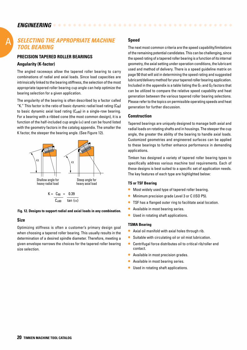
The angled raceways allow the tapered roller bearing to carry combinations of radial and axial loads. Since load capacities are intrinsically linked to the bearing stiffness, the selection of the most appropriate tapered roller bearing cup angle can help optimize the bearing selection for a given application.
The angularity of the bearing is often described by a factor called “K.” This factor is the ratio of basic dynamic radial load rating (C90) to basic dynamic axial load rating (Ca90) in a single-row bearing. For a bearing with a ribbed cone (the most common design), it is a function of the half-included cup angle (α) and can be found listed with the geometry factors in the catalog appendix. The smaller the K factor, the steeper the bearing angle. (See Figure 12).
Size
Optimizing stiffness is often a customer’s primary design goal when choosing a tapered roller bearing. This usually results in the determination of a desired spindle diameter. Therefore, meeting a given envelope narrows the choices for the tapered roller bearing size selection.
Speed
The next most common criteria are the speed capability/limitations of the remaining potential candidates. This can be challenging, since the speed rating of a tapered roller bearing is a function of its internal geometry, the axial setting under operation conditions, the lubricant used and method of delivery. There is a speed guideline matrix on page 50 that will aid in determining the speed rating and suggested lubricant/delivery method for your tapered roller bearing application. Included in the appendix is a table listing the G1 and G2 factors that can be utilized to compare the relative speed capability and heat generation between the various tapered roller bearing selections. Please refer to the topics on permissible operating speeds and heat generation for further discussion.
Construction
Tapered bearings are uniquely designed to manage both axial and radial loads on rotating shafts and in housings. The steeper the cup angle, the greater the ability of the bearing to handle axial loads. Customized geometries and engineered surfaces can be applied to these bearings to further enhance performance in demanding applications.
Timken has designed a variety of tapered roller bearing types to specifically address various machine tool requirements. Each of these designs is best suited to a specific set of application needs. The key features of each type are highlighted below:
TS or TSF Bearing
• Most widely used type of tapered roller bearing.
• Minimum precision grade Level 3 or C (ISO P5).
• TSF has a flanged outer ring to facilitate axial location.
• Available in most bearing series.
• Used in rotating shaft applications.
TSMA Bearing
• Axial oil manifold with axial holes through rib.
• Suitable with circulating oil or oil mist lubrication.
• Centrifugal force distributes oil to critical rib/roller end contact.
• Available in most precision grades.
• Available in most bearing series.
• Used in rotating shaft applications.
Fig. 12. Designs to support radial and axial loads in any combination.
K = C90 = 0.39
Ca90 tan (α)
α α
Shallow angle forheavy radial load
Steep angle for heavy axial load
Shallow angle forheavy radial load
Steep angle for heavy axial load
ENGINEERING
A
TIMKEN MACHINE TOOL CATALOG 21
Hydra-Rib Bearing
• Designed to maintain optimum spindle system preload.
• Floating outer ring rib is positioned by a “pressure” system.
• Rib in contact with the large roller ends instead of the usual fixed inner ring rib.
• Variable preload setting adaptable to manual, tape, or computer control.
• Wide speed range with optimum preload setting.
• Improved spindle accuracy.
• Improved static and dynamic stiffness.
• Lower operating temperatures.
• Heavier cuts with better tool life.
Spring-Rib Bearing
• Designed to maintain optimum spindle system preload.
• Floating outer ring rib is positioned by a “spring” system – pressurizing system not required.
• Rib in contact with the large roller ends instead of the usual fixed inner ring rib.
• Improved spindle accuracy.
• Improved static and dynamic stiffness.
• Heavier cuts with better tool life.
Crossed Roller Bearing
• Designed to resist overturning loads.
• Steep-angled geometry provides wider effective spread.
• High tilting stiffness.
• Adjustable design for optimum preload.
• Compact design reduces space requirement.
• Reduced application machining costs.
End Play (Preload)
The end play of a tapered roller bearing during installation affects:
• Load zone control, impacting bearing life.
• System rigidity, impacting deflection.
• Housing and shaft diameter tolerances.
End play/preload setting is determined based on desired stiffness, reduction in heat generation, and optimal rated life. For information on setting, please see page 97.
Precision Class
Typically, once the most appropriate bearing part number is identified for a particular application, the final parameter is the desired precision level. Standard class tapered roller bearings have crowned or enhanced profiles for races and rollers. Timken precision tapered roller bearings have straight profiles with running accuracy and performance meeting ISO P5, ISO P4, and ISO P2 levels. The Precision Plus series offers total radial runout of less than a single micron, exceeding the ISO P2 precision level and allowing for improved accuracy. The suggested assembly and/or inspection code (precision class and performance code) can be applied to the chosen part number to obtain the necessary precision level.
Other
Consult Timken for suggestions related to appropriate bearing enhancements that can improve the performance of your application.
Such enhancements might include unique precision levels, conversion of a TS-style design to a (flanged) TSF or (multi-row) TDO, or possibly ceramic rolling elements for better stiffness and speedability.
ENGINEERING
A
22 TIMKEN MACHINE TOOL CATALOG
0˚ 15˚ 25˚60˚
SUPER PRECISION BALL BEARINGS
As previously noted, optimizing speed, stiffness, accuracy and load capacity is often a customer’s primary design goal. This usually results in the identification of several characteristics that will determine the final bearing selection. The following design variables influence bearing performance as noted.
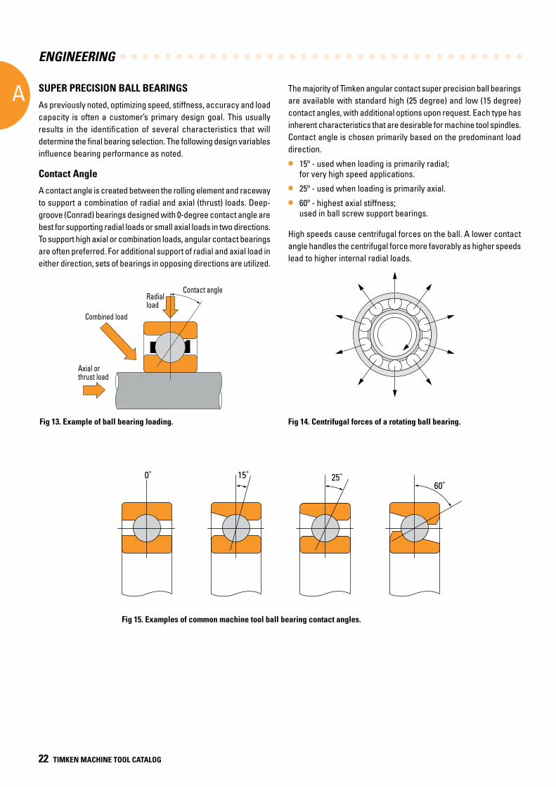
Contact Angle
A contact angle is created between the rolling element and raceway to support a combination of radial and axial (thrust) loads. Deep- groove (Conrad) bearings designed with 0-degree contact angle are best for supporting radial loads or small axial loads in two directions. To support high axial or combination loads, angular contact bearings are often preferred. For additional support of radial and axial load in either direction, sets of bearings in opposing directions are utilized.
The majority of Timken angular contact super precision ball bearings are available with standard high (25 degree) and low (15 degree) contact angles, with additional options upon request. Each type has inherent characteristics that are desirable for machine tool spindles. Contact angle is chosen primarily based on the predominant load direction.
• 15º - used when loading is primarily radial; for very high speed applications.
• 25º - used when loading is primarily axial.
• 60º - highest axial stiffness; used in ball screw support bearings.
High speeds cause centrifugal forces on the ball. A lower contact angle handles the centrifugal force more favorably as higher speeds lead to higher internal radial loads.
Fig 15. Examples of common machine tool ball bearing contact angles.
Axial orthrust load
Combined load
Radial load
Contact angle
Combined load
Axial orthrust load
Radial load
Contact angle
Fig 13 . Example of ball bearing loading . Fig 14 . Centrifugal forces of a rotating ball bearing .
ENGINEERING
A
TIMKEN MACHINE TOOL CATALOG 23
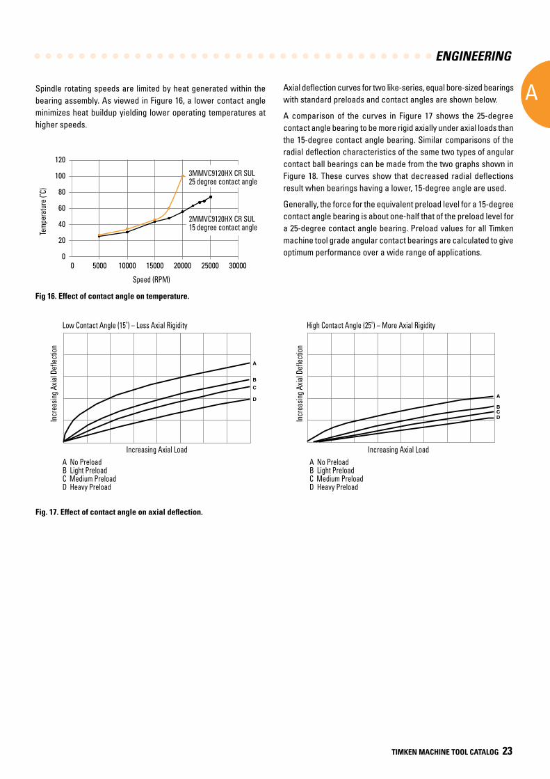
Spindle rotating speeds are limited by heat generated within the bearing assembly. As viewed in Figure 16, a lower contact angle minimizes heat buildup yielding lower operating temperatures at higher speeds.
Fig 16 . Effect of contact angle on temperature .
Axial deflection curves for two like-series, equal bore-sized bearings with standard preloads and contact angles are shown below.
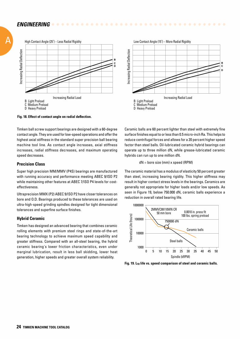
A comparison of the curves in Figure 17 shows the 25-degree contact angle bearing to be more rigid axially under axial loads than the 15-degree contact angle bearing. Similar comparisons of the radial deflection characteristics of the same two types of angular contact ball bearings can be made from the two graphs shown in Figure 18. These curves show that decreased radial deflections result when bearings having a lower, 15-degree angle are used.
Generally, the force for the equivalent preload level for a 15-degree contact angle bearing is about one-half that of the preload level for a 25-degree contact angle bearing. Preload values for all Timken machine tool grade angular contact bearings are calculated to give optimum performance over a wide range of applications.
Fig. 17. Effect of contact angle on axial deflection.
A
BC
D A
BCD
Low Contact Angle (15˚) – Less Axial Rigidity
Incr
easi
ng A
xial
Defl
ectio
n
Increasing Axial LoadA No Preload B Light Preload C Medium PreloadD Heavy Preload
Incr
easi
ng A
xial
Defl
ectio
n
High Contact Angle (25˚) – More Axial Rigidity
Increasing Axial LoadA No Preload B Light Preload C Medium PreloadD Heavy Preload
Low Contact Angle (15˚) – Less Axial Rigidity
Increasing Axial Load
Incr
easin
g Axia
l Defl
ectio
n
Incr
easin
g Axia
l Defl
ectio
n
A No PreloadB Light Preload C Medium PreloadD Heavy Preload
A No PreloadB Light Preload C Medium PreloadD Heavy Preload
Increasing Axial Load
High Contact Angle (25˚) – More Axial Rigidity
Tem
pera
ture
(˚C)
120
100
80
60
40
20
00 5000 10000 15000 20000
Speed (RPM)
25000 30000
Bearing Outer Ring Temperature Versus Shaft Speed
2MMVC9120HX CR SUL15 degree contact angle
3MMVC9120HX CR SUL25 degree contact angle3MMVC9120HX CR SUL25 degree contact angle
2MMVC9120HX CR SUL15 degree contact angle
Speed (RPM)
Temp
erat
ure (
˚C)
ENGINEERING
A
24 TIMKEN MACHINE TOOL CATALOG
Timken ball screw support bearings are designed with a 60-degree contact angle. They are used for low-speed operations and offer the highest axial stiffness in the standard super precision ball bearing machine tool line. As contact angle increases, axial stiffness increases, radial stiffness decreases, and maximum operating speed decreases.
Precision Class
Super high precision MM/MMV (P4S) bearings are manufactured with running accuracy and performance meeting ABEC 9/ISO P2 while maintaining other features at ABEC 7/ISO P4 levels for cost-effectiveness.
Ultraprecision MMX (P2) ABEC 9/ISO P2 have closer tolerances on bore and O.D. Bearings produced to these tolerances are used on ultra-high-speed grinding spindles designed for tight dimensional tolerances and superfine surface finishes.
Hybrid Ceramic
Timken has designed an advanced bearing that combines ceramic rolling elements with premium steel rings and state-of-the-art bearing technology to achieve maximum speed capability and greater stiffness. Compared with an all-steel bearing, the hybrid ceramic bearing's lower friction characteristics, even under marginal lubrication, result in less ball skidding, lower heat generation, higher speeds and greater overall system reliability.
Ceramic balls are 60 percent lighter than steel with extremely fine surface finishes equal to or less than 0.5 micro-inch Ra. This helps to reduce centrifugal forces and allows for a 20 percent higher speed factor than steel balls. Oil-lubricated ceramic hybrid bearings can operate up to three million dN, while grease-lubricated ceramic hybrids can run up to one million dN.
dN = bore size (mm) x speed (RPM)
The ceramic material has a modulus of elasticity 50 percent greater than steel, increasing bearing rigidity. This higher stiffness may result in higher contact stress levels in the bearings. Ceramics are generally not appropriate for higher loads and/or low speeds. As seen in Figure 19, below 750.000 dN, ceramic balls experience a reduction in overall rated bearing life.
Fig. 18. Effect of contact angle on radial deflection.
Fig. 19. L10 life vs. speed comparison of steel and ceramic balls.
High Contact Angle (25˚) – Less Radial Rigidity Low Contact Angle (15˚) – More Radial Rigidity
Incr
easi
ng R
adia
l Defl
ectio
n
BCD
Incr
easi
ng R
adia
l Defl
ectio
n
Increasing Radial LoadB Light Preload C Medium Preload D Heavy Preload
BCD
Increasing Radial LoadB Light Preload C Medium Preload D Heavy Preload
High Contact Angle (25˚) – Less Radial Rigidity Low Contact Angle (15˚) – More Radial Rigidity
Increasing Radial Load Increasing Radial Load
Incr
easin
g Rad
ial D
eflec
tion
Incr
easin
g Rad
ial D
eflec
tion
B Light Preload C Medium PreloadD Heavy Preload
B Light Preload C Medium PreloadD Heavy Preload
Theo
retic
al L
ife (h
ours
)
1000000
100000
10000
10000 105 15 20 25
Spindle (kRPM)
30 35 40 45 50
Steel balls
Ceramic balls
0.0010 in. press fit100 lbs. spring preload
2MMVC99110WN CR50 mm bore
750000 dN
Spindle (kRPM)
Theo
retic
al Lif
e (ho
urs)
Steel balls
Ceramic balls
2MMVC99110WN CR50 mm bore 0.0010 in. press fit
100 lbs. spring preload
ENGINEERING
A
TIMKEN MACHINE TOOL CATALOG 25
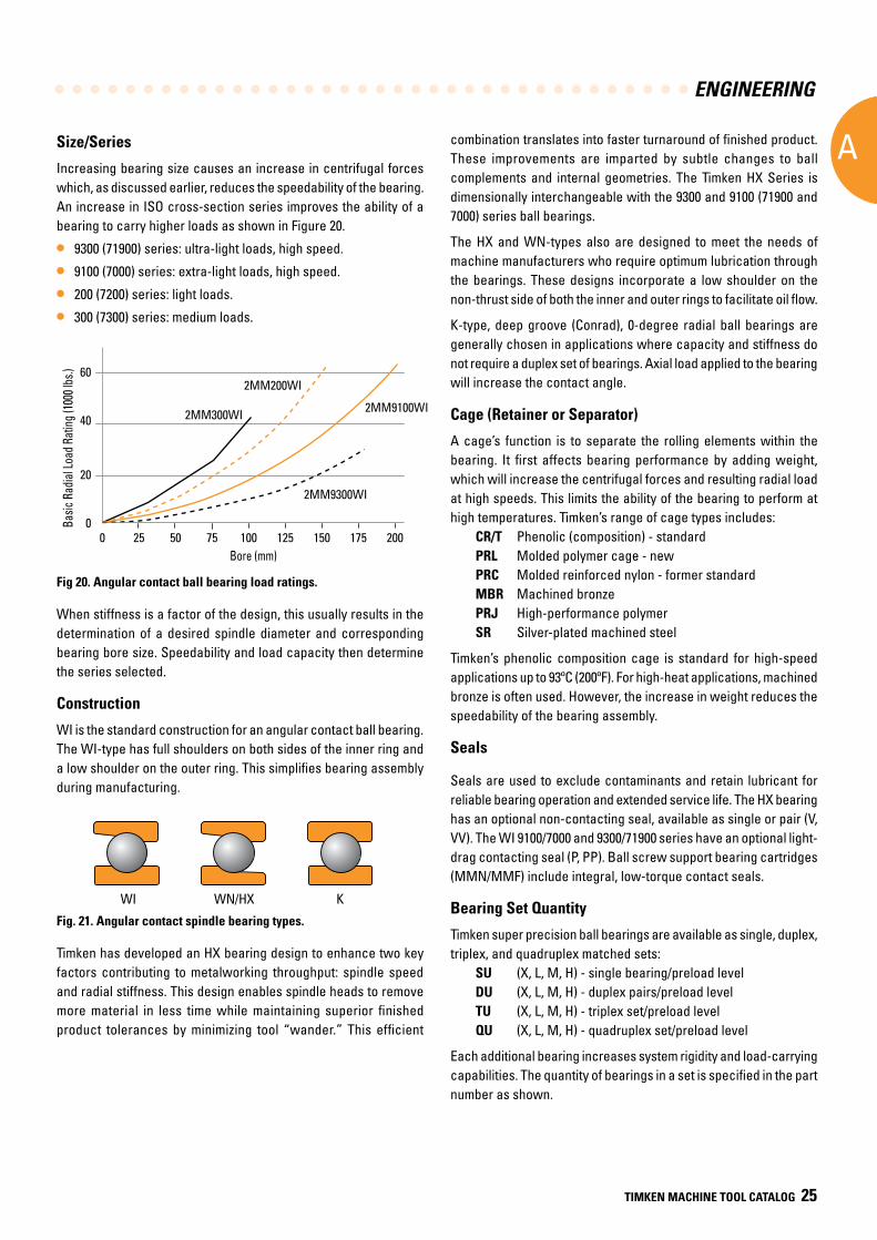
Size/Series
Increasing bearing size causes an increase in centrifugal forces which, as discussed earlier, reduces the speedability of the bearing. An increase in ISO cross-section series improves the ability of a bearing to carry higher loads as shown in Figure 20.
• 9300 (71900) series: ultra-light loads, high speed.
• 9100 (7000) series: extra-light loads, high speed.
• 200 (7200) series: light loads.
• 300 (7300) series: medium loads.
Fig 20. Angular contact ball bearing load ratings.
When stiffness is a factor of the design, this usually results in the determination of a desired spindle diameter and corresponding bearing bore size. Speedability and load capacity then determine the series selected.
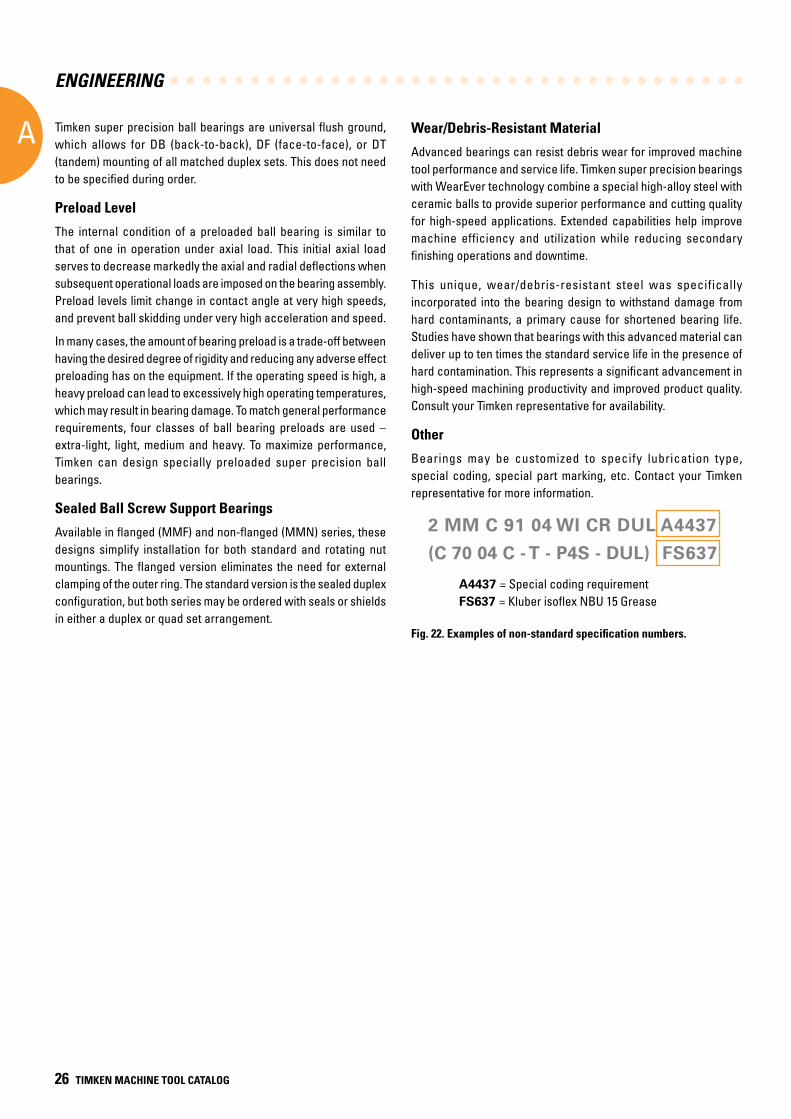
Construction
WI is the standard construction for an angular contact ball bearing. The WI-type has full shoulders on both sides of the inner ring and a low shoulder on the outer ring. This simplifies bearing assembly during manufacturing.
Fig. 21. Angular contact spindle bearing types.
Timken has developed an HX bearing design to enhance two key factors contributing to metalworking throughput: spindle speed and radial stiffness. This design enables spindle heads to remove more material in less time while maintaining superior finished product tolerances by minimizing tool “wander.” This efficient
combination translates into faster turnaround of finished product. These improvements are imparted by subtle changes to ball complements and internal geometries. The Timken HX Series is dimensionally interchangeable with the 9300 and 9100 (71900 and 7000) series ball bearings.
The HX and WN-types also are designed to meet the needs of machine manufacturers who require optimum lubrication through the bearings. These designs incorporate a low shoulder on the non-thrust side of both the inner and outer rings to facilitate oil flow.
K-type, deep groove (Conrad), 0-degree radial ball bearings are generally chosen in applications where capacity and stiffness do not require a duplex set of bearings. Axial load applied to the bearing will increase the contact angle.
Cage (Retainer or Separator)
A cage’s function is to separate the rolling elements within the bearing. It first affects bearing performance by adding weight, which will increase the centrifugal forces and resulting radial load at high speeds. This limits the ability of the bearing to perform at high temperatures. Timken’s range of cage types includes:
CR/T Phenolic (composition) - standardPRL Molded polymer cage - new PRC Molded reinforced nylon - former standard MBR Machined bronze PRJ High-performance polymer SR Silver-plated machined steel
Timken’s phenolic composition cage is standard for high-speed applications up to 93ºC (200ºF). For high-heat applications, machined bronze is often used. However, the increase in weight reduces the speedability of the bearing assembly.
Seals
Seals are used to exclude contaminants and retain lubricant for reliable bearing operation and extended service life. The HX bearing has an optional non-contacting seal, available as single or pair (V, VV). The WI 9100/7000 and 9300/71900 series have an optional light-drag contacting seal (P, PP). Ball screw support bearing cartridges (MMN/MMF) include integral, low-torque contact seals.
Bearing Set Quantity
Timken super precision ball bearings are available as single, duplex, triplex, and quadruplex matched sets:
SU (X, L, M, H) - single bearing/preload levelDU (X, L, M, H) - duplex pairs/preload levelTU (X, L, M, H) - triplex set/preload level QU (X, L, M, H) - quadruplex set/preload level
Each additional bearing increases system rigidity and load-carrying capabilities. The quantity of bearings in a set is specified in the part number as shown.
WN/HXWI K
Basi
c Ra
dial
Loa
d Ra
ting
(100
0 lb
s.)
60
40
20
00 5025 75
Bore (mm)
100 125 150 175 200
2MM9300WI
2MM9100WI
2MM200WI
2MM300WI
High Contact Angle (25˚) – Less Radial Rigidity Low Contact Angle (15˚) – More Radial Rigidity
Incr
easi
ng R
adia
l Defl
ectio
n
BCD
Incr
easi
ng R
adia
l Defl
ectio
n
Increasing Radial LoadB Light Preload C Medium Preload D Heavy Preload
BCD
Increasing Radial LoadB Light Preload C Medium Preload D Heavy Preload
Basic
Rad
ial Lo
ad R
ating
(100
0 lbs
.)
Bore (mm)
ENGINEERING
A
26 TIMKEN MACHINE TOOL CATALOG
Timken super precision ball bearings are universal flush ground, which allows for DB (back-to-back), DF (face-to-face), or DT (tandem) mounting of all matched duplex sets. This does not need to be specified during order.
Preload Level
The internal condition of a preloaded ball bearing is similar to that of one in operation under axial load. This initial axial load serves to decrease markedly the axial and radial deflections when subsequent operational loads are imposed on the bearing assembly. Preload levels limit change in contact angle at very high speeds, and prevent ball skidding under very high acceleration and speed.
In many cases, the amount of bearing preload is a trade-off between having the desired degree of rigidity and reducing any adverse effect preloading has on the equipment. If the operating speed is high, a heavy preload can lead to excessively high operating temperatures, which may result in bearing damage. To match general performance requirements, four classes of ball bearing preloads are used – extra-light, light, medium and heavy. To maximize performance, Timken can design specially preloaded super precision ball bearings.
Sealed Ball Screw Support Bearings
Available in flanged (MMF) and non-flanged (MMN) series, these designs simplify installation for both standard and rotating nut mountings. The flanged version eliminates the need for external clamping of the outer ring. The standard version is the sealed duplex configuration, but both series may be ordered with seals or shields in either a duplex or quad set arrangement.
Wear/Debris-Resistant Material
Advanced bearings can resist debris wear for improved machine tool performance and service life. Timken super precision bearings with WearEver technology combine a special high-alloy steel with ceramic balls to provide superior performance and cutting quality for high-speed applications. Extended capabilities help improve machine efficiency and utilization while reducing secondary finishing operations and downtime.
This unique, wear/debris-resistant steel was specifically incorporated into the bearing design to withstand damage from hard contaminants, a primary cause for shortened bearing life. Studies have shown that bearings with this advanced material can deliver up to ten times the standard service life in the presence of hard contamination. This represents a significant advancement in high-speed machining productivity and improved product quality. Consult your Timken representative for availability.
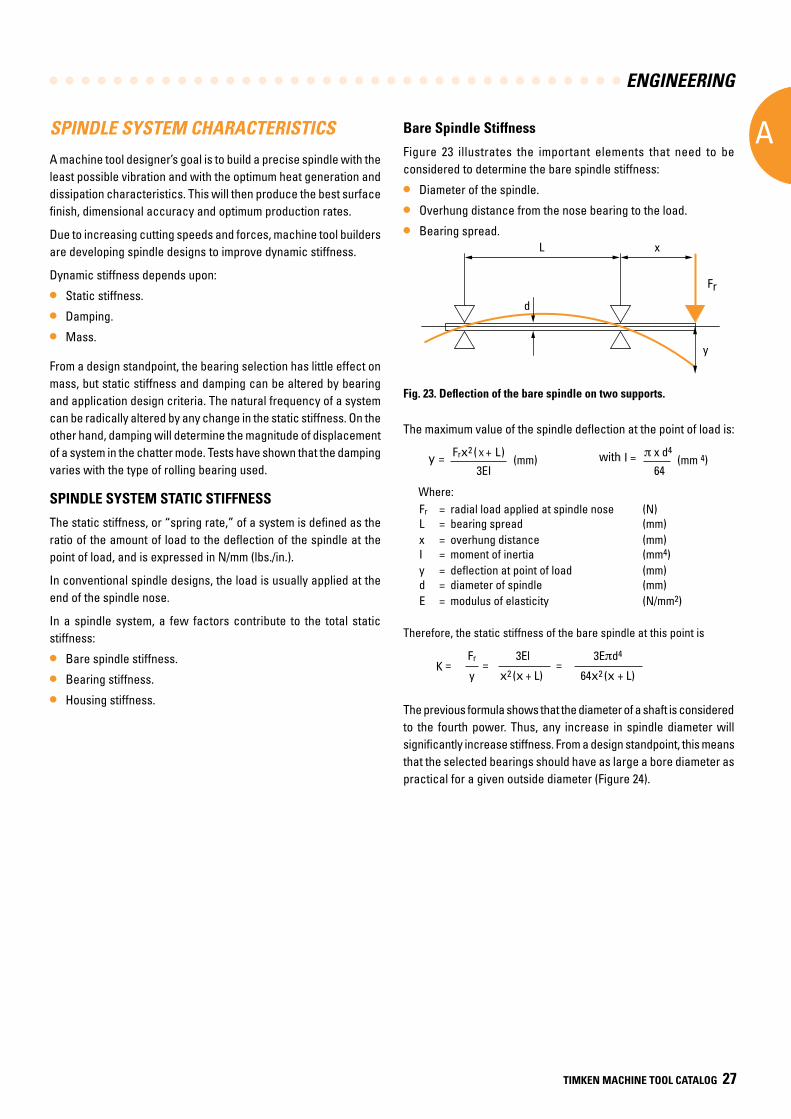
Other
Bearings may be customized to specify lubrication type, special coding, special part marking, etc. Contact your Timken representative for more information.
2 MM C 91 04 WI CR DUL A4437
(C 70 04 C - T - P4S - DUL) FS637
A4437 = Special coding requirement FS637 = Kluber isoflex NBU 15 Grease
Fig. 22. Examples of non-standard specification numbers.
ENGINEERING
A
TIMKEN MACHINE TOOL CATALOG 27
SPINDLE SYSTEM CHARACTERISTICS
A machine tool designer’s goal is to build a precise spindle with the least possible vibration and with the optimum heat generation and dissipation characteristics. This will then produce the best surface finish, dimensional accuracy and optimum production rates.
Due to increasing cutting speeds and forces, machine tool builders are developing spindle designs to improve dynamic stiffness.
Dynamic stiffness depends upon:
• Static stiffness.
• Damping.
• Mass.
From a design standpoint, the bearing selection has little effect on mass, but static stiffness and damping can be altered by bearing and application design criteria. The natural frequency of a system can be radically altered by any change in the static stiffness. On the other hand, damping will determine the magnitude of displacement of a system in the chatter mode. Tests have shown that the damping varies with the type of rolling bearing used.
SPINDLE SYSTEM STATIC STIFFNESS
The static stiffness, or “spring rate,” of a system is defined as the ratio of the amount of load to the deflection of the spindle at the point of load, and is expressed in N/mm (lbs./in.).
In conventional spindle designs, the load is usually applied at the end of the spindle nose.
In a spindle system, a few factors contribute to the total static stiffness:
• Bare spindle stiffness.
• Bearing stiffness.
• Housing stiffness.
Bare Spindle Stiffness
Figure 23 illustrates the important elements that need to be considered to determine the bare spindle stiffness:
• Diameter of the spindle.
• Overhung distance from the nose bearing to the load.
• Bearing spread.
Fig. 23. Deflection of the bare spindle on two supports.
The maximum value of the spindle deflection at the point of load is:
EnginEEring
A
30 TIMKEN MACHINE TOOL CATALOG TIMKEN MACHINE TOOL CATALOG 31
SPINDLE SYSTEM CHARACTERISTICS
A machine tool designer’s goal is to build a precise spindle with the least possible vibration and with the optimum heat generation and dissipation characteristics. This will then produce the best surface finish, dimensional accuracy and optimum production rates.
Due to increasing cutting speeds and forces, machine tool builders are developing spindle designs to improve dynamic stiffness.
Dynamic stiffness depends upon:
• Static stiffness.
• Damping.
• Mass.
From a design standpoint, the bearing selection has little effect on mass, but static stiffness and damping can be altered by bearing and application design criteria. The natural frequency of a system can be radically altered by any change in the static stiffness. On the other hand, damping will determine the magnitude of displacement of a system in the chatter mode. Tests have shown that the damping varies with the type of rolling bearing used.
SPINDLE SYSTEM STATIC STIFFNESS
The static stiffness, or “spring rate,” of a system is defined as the ratio of the amount of load to the deflection of the spindle at the point of load, and is expressed in N/mm (lbs./in.).
In conventional spindle designs, the load is usually applied at the end of the spindle nose.
In a spindle system, a few factors contribute to the total static stiffness:
• Bare spindle stiffness.
• Bearing stiffness.
• Housing stiffness.
Bare Spindle Stiffness
Figure 23 illustrates the important elements that need to be considered to determine the bare spindle stiffness:
• Diameter of the spindle.
• Overhung distance from the nose bearing to the load.
• Bearing spread.
Fig. 23. Deflection of the bare spindle on two supports.
The maximum value of the spindle deflection at the point of load is: y = Frx2 ( x + L)
(mm) with I = π x d4
(mm 4) 3EI 64 Where: Fr = radial load applied at spindle nose (N) L = bearing spread (mm) x = overhung distance (mm) I = moment of inertia (mm4) y = deflection at point of load (mm) d = diameter of spindle (mm) E = modulus of elasticity (N/mm2)
Therefore, the static stiffness of the bare spindle at this point is:
Fr 3El 3Eπd4K =
y = x2 (x + L)
= 64x2 (x + L)
The previous formula shows that the diameter of a shaft is considered to the fourth power. Thus, any increase in spindle diameter will significantly increase stiffness. From a design standpoint, this means that the selected bearings should have as large a bore diameter as practical for a given outside diameter (Figure 24).
xL
d
y
Fr
with
Where: Fr = radial load applied at spindle nose (N) L = bearing spread (mm) x = overhung distance (mm) I = moment of inertia (mm4) y = deflection at point of load (mm) d = diameter of spindle (mm) E = modulus of elasticity (N/mm2)
Therefore, the static stiffness of the bare spindle at this point is
EnginEEring
A
30 TIMKEN MACHINE TOOL CATALOG TIMKEN MACHINE TOOL CATALOG 31
SPINDLE SYSTEM CHARACTERISTICS
A machine tool designer’s goal is to build a precise spindle with the least possible vibration and with the optimum heat generation and dissipation characteristics. This will then produce the best surface finish, dimensional accuracy and optimum production rates.
Due to increasing cutting speeds and forces, machine tool builders are developing spindle designs to improve dynamic stiffness.
Dynamic stiffness depends upon:
• Static stiffness.
• Damping.
• Mass.
From a design standpoint, the bearing selection has little effect on mass, but static stiffness and damping can be altered by bearing and application design criteria. The natural frequency of a system can be radically altered by any change in the static stiffness. On the other hand, damping will determine the magnitude of displacement of a system in the chatter mode. Tests have shown that the damping varies with the type of rolling bearing used.
SPINDLE SYSTEM STATIC STIFFNESS
The static stiffness, or “spring rate,” of a system is defined as the ratio of the amount of load to the deflection of the spindle at the point of load, and is expressed in N/mm (lbs./in.).
In conventional spindle designs, the load is usually applied at the end of the spindle nose.
In a spindle system, a few factors contribute to the total static stiffness:
• Bare spindle stiffness.
• Bearing stiffness.
• Housing stiffness.
Bare Spindle Stiffness
Figure 23 illustrates the important elements that need to be considered to determine the bare spindle stiffness:
• Diameter of the spindle.
• Overhung distance from the nose bearing to the load.
• Bearing spread.
Fig. 23. Deflection of the bare spindle on two supports.
The maximum value of the spindle deflection at the point of load is: y = Frx2 ( x + L)
(mm) with I = π x d4
(mm 4) 3EI 64 Where: Fr = radial load applied at spindle nose (N) L = bearing spread (mm) x = overhung distance (mm) I = moment of inertia (mm4) y = deflection at point of load (mm) d = diameter of spindle (mm) E = modulus of elasticity (N/mm2)
Therefore, the static stiffness of the bare spindle at this point is:
Fr 3El 3Eπd4K =
y = x2 (x + L)
= 64x2 (x + L)
The previous formula shows that the diameter of a shaft is considered to the fourth power. Thus, any increase in spindle diameter will significantly increase stiffness. From a design standpoint, this means that the selected bearings should have as large a bore diameter as practical for a given outside diameter (Figure 24).
xL
d
y
Fr
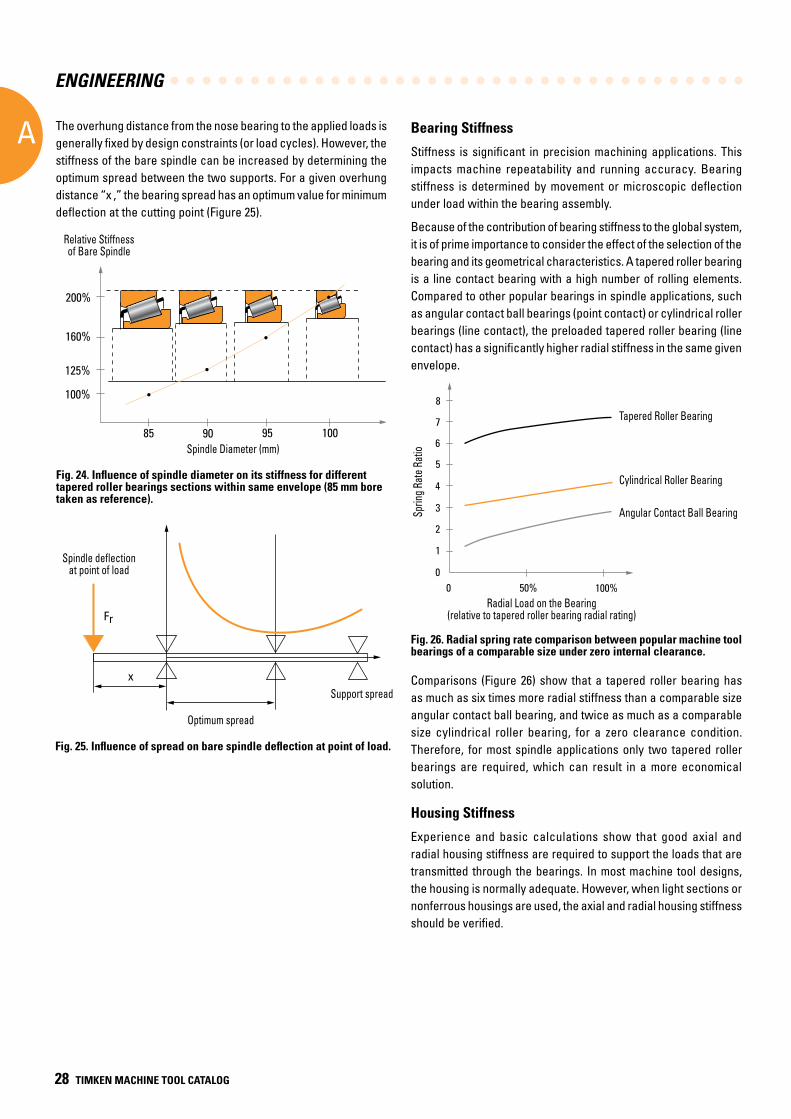
ENGINEERING
A
28 TIMKEN MACHINE TOOL CATALOG
The overhung distance from the nose bearing to the applied loads is generally fixed by design constraints (or load cycles). However, the stiffness of the bare spindle can be increased by determining the optimum spread between the two supports. For a given overhung distance “x ,” the bearing spread has an optimum value for minimum deflection at the cutting point (Figure 25).
Bearing Stiffness
Stiffness is significant in precision machining applications. This impacts machine repeatability and running accuracy. Bearing stiffness is determined by movement or microscopic deflection under load within the bearing assembly.
Because of the contribution of bearing stiffness to the global system, it is of prime importance to consider the effect of the selection of the bearing and its geometrical characteristics. A tapered roller bearing is a line contact bearing with a high number of rolling elements. Compared to other popular bearings in spindle applications, such as angular contact ball bearings (point contact) or cylindrical roller bearings (line contact), the preloaded tapered roller bearing (line contact) has a significantly higher radial stiffness in the same given envelope.
Fig. 26. Radial spring rate comparison between popular machine tool bearings of a comparable size under zero internal clearance.
Comparisons (Figure 26) show that a tapered roller bearing has as much as six times more radial stiffness than a comparable size angular contact ball bearing, and twice as much as a comparable size cylindrical roller bearing, for a zero clearance condition. Therefore, for most spindle applications only two tapered roller bearings are required, which can result in a more economical solution.
Housing Stiffness
Experience and basic calculations show that good axial and radial housing stiffness are required to support the loads that are transmitted through the bearings. In most machine tool designs, the housing is normally adequate. However, when light sections or nonferrous housings are used, the axial and radial housing stiffness should be verified.
Fig. 25. Influence of spread on bare spindle deflection at point of load.
Relative Stiffnessof Bare Spindle
200%
160%
125%
100%
85 90 95 100Spindle Diameter (mm)
Fig. 24. Influence of spindle diameter on its stiffness for different tapered roller bearings sections within same envelope (85 mm bore taken as reference).
Spindle Diameter (mm)
Relative Stiffnessof Bare Spindle
Fr
x
Spindle deflectionat point of load
Optimum spread
Support spread
Spindle deflectionat point of load
Optimum spread
Support spread
14000
Max
Spe
ed (R
PM)
12000
10000
8000
4000
6000
2000
070 100 130 160
Bore (mm)
Sprin
g Ra
te R
atio
Tapered Roller Bearing
Cylindrical Roller Bearing
Angular Contact Ball Bearing
Radial Load on the Bearing(relative to tapered roller bearing radial rating)
7
0 50% 100%0
1
2
3
4
5
6
8
Ball Bearing (2MM9100WI)Tapered Roller Bearing (TS Metric)
Tapered Roller Bearing
Cylindrical Roller Bearing
Angular Contact Ball BearingSprin
g Rat
e Rat
io
Radial Load on the Bearing(relative to tapered roller bearing radial rating)
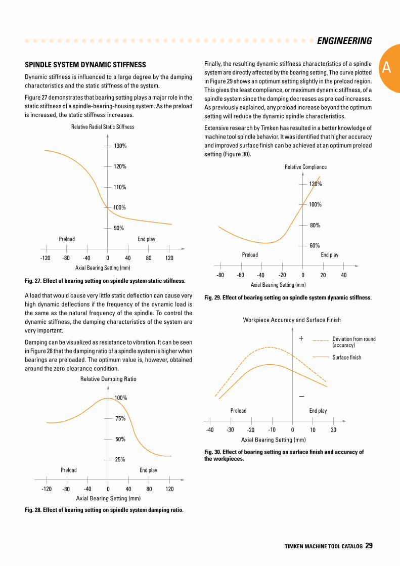
ENGINEERING
A
TIMKEN MACHINE TOOL CATALOG 29
SPINDLE SYSTEM DYNAMIC STIFFNESS
Dynamic stiffness is influenced to a large degree by the damping characteristics and the static stiffness of the system.
Figure 27 demonstrates that bearing setting plays a major role in the static stiffness of a spindle-bearing-housing system. As the preload is increased, the static stiffness increases.
Fig. 27. Effect of bearing setting on spindle system static stiffness.
A load that would cause very little static deflection can cause very high dynamic deflections if the frequency of the dynamic load is the same as the natural frequency of the spindle. To control the dynamic stiffness, the damping characteristics of the system are very important.
Damping can be visualized as resistance to vibration. It can be seen in Figure 28 that the damping ratio of a spindle system is higher when bearings are preloaded. The optimum value is, however, obtained around the zero clearance condition.
Fig. 28. Effect of bearing setting on spindle system damping ratio.
Finally, the resulting dynamic stiffness characteristics of a spindle system are directly affected by the bearing setting. The curve plotted in Figure 29 shows an optimum setting slightly in the preload region. This gives the least compliance, or maximum dynamic stiffness, of a spindle system since the damping decreases as preload increases. As previously explained, any preload increase beyond the optimum setting will reduce the dynamic spindle characteristics.
Extensive research by Timken has resulted in a better knowledge of machine tool spindle behavior. It was identified that higher accuracy and improved surface finish can be achieved at an optimum preload setting (Figure 30).
Fig. 29. Effect of bearing setting on spindle system dynamic stiffness.
Fig. 30. Effect of bearing setting on surface finish and accuracy of the workpieces.
100%
-120
Relative Radial Static Stiffness
Axial Bearing Setting (μm)
-80 -40 40 80 1200
90%
110%
120%
130%
Preload End play
Relative Radial Static Stiffness
Axial Bearing Setting (mm)
Preload End play60%
Relative Compliance
Axial Bearing Setting (μm)
-80 -40 20 400
80%
100%
-60 -20
Preload End play
120%
Preload
Relative Compliance
Axial Bearing Setting (mm)
End play
25%
Relative Damping Ratio
Axial Bearing Setting (μm)
120-80 40 800
50%
75%
-120 -40
Preload End play
100%
Preload
Relative Damping Ratio
Axial Bearing Setting (mm)
End play
Workpiece Accuracy and Surface Finish
Axial Bearing Setting (μm)
-40 -20 10 200-30 -10
Preload End play
+
–
Deviation fromround (accuracy)
Surface finish
Preload
Deviation from round (accuracy)
Surface finish
Workpiece Accuracy and Surface Finish
Axial Bearing Setting (mm)
End play
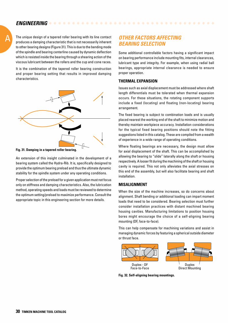
ENGINEERING
A
30 TIMKEN MACHINE TOOL CATALOG
OTHER FACTORS AFFECTING BEARING SELECTION
Some additional controllable factors having a significant impact on bearing performance include mounting fits, internal clearances, lubricant type and integrity. For example, when using radial ball bearings, appropriate internal clearance is needed to ensure proper operation.
THERMAL EXPANSION
Issues such as axial displacement must be addressed where shaft length differentials must be tolerated when thermal expansion occurs. For these situations, the rotating component supports include a fixed (locating) and floating (non-locating) bearing arrangement.
The fixed bearing is subject to combination loads and is usually placed nearest the working end of the shaft to minimize motion and thereby maintain workpiece accuracy. Installation considerations for the typical fixed bearing positions should note the fitting suggestions listed in this catalog. These are compiled from a wealth of experience in a wide range of operating conditions.
Where floating bearings are necessary, the design must allow for axial displacement of the shaft. This can be accomplished by allowing the bearing to “slide” laterally along the shaft or housing respectively. A looser fit during the machining of the shaft or housing cavity is required. This not only alleviates the axial stresses on this end of the assembly, but will also facilitate bearing and shaft installation.
MISALIGNMENT
When the size of the machine increases, so do concerns about alignment. Shaft bending or additional loading can impart moment loads that need to be considered. Bearing selection must further consider installation practices with distant machined bearing housing cavities. Manufacturing limitations to position housing bores might encourage the choice of a self-aligning bearing mounting (DF, face-to-face).
This can help compensate for machining variations and assist in managing dynamic forces by featuring a spherical outside diameter or thrust face.
Fig. 32. Self-aligning bearing mountings.
The unique design of a tapered roller bearing with its line contact produces a damping characteristic that is not necessarily inherent to other bearing designs (Figure 31). This is due to the bending mode of the spindle and bearing centerline caused by dynamic deflection which is resisted inside the bearing through a shearing action of the viscous lubricant between the rollers and the cup and cone races.
It is the combination of the tapered roller bearing construction and proper bearing setting that results in improved damping characteristics.
Fig. 31. Damping in a tapered roller bearing.
An extension of this insight culminated in the development of a bearing system called the Hydra-Rib. It is, specifically designed to provide the optimum bearing preload and thus the ultimate dynamic stability for the spindle system under any operating conditions.
Proper selection of the preload for a given application must not focus only on stiffness and damping characteristics. Also, the lubrication method, operating speeds and loads must be reviewed to determine the optimum setting/preload to maximize performance. Consult the appropriate topic in this engineering section for more details.
Duplex - DFFace-to-Face
DuplexDirect Mounting
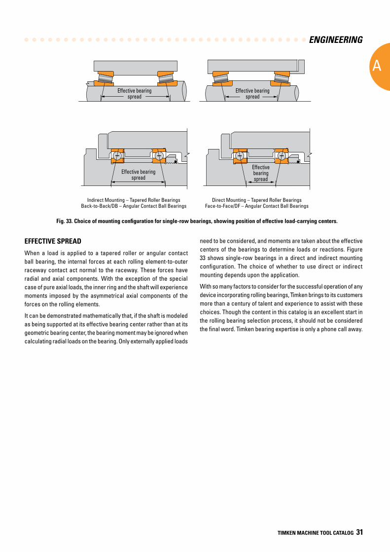
ENGINEERING
A
TIMKEN MACHINE TOOL CATALOG 31
need to be considered, and moments are taken about the effective centers of the bearings to determine loads or reactions. Figure 33 shows single-row bearings in a direct and indirect mounting configuration. The choice of whether to use direct or indirect mounting depends upon the application.
With so many factors to consider for the successful operation of any device incorporating rolling bearings, Timken brings to its customers more than a century of talent and experience to assist with these choices. Though the content in this catalog is an excellent start in the rolling bearing selection process, it should not be considered the final word. Timken bearing expertise is only a phone call away.
Indirect Mounting – Tapered Roller BearingsBack-to-Back/DB – Angular Contact Ball Bearings
Direct Mounting – Tapered Roller BearingsFace-to-Face/DF – Angular Contact Ball Bearings
EFFECTIVE SPREAD
When a load is applied to a tapered roller or angular contact ball bearing, the internal forces at each rolling element-to-outer raceway contact act normal to the raceway. These forces have radial and axial components. With the exception of the special case of pure axial loads, the inner ring and the shaft will experience moments imposed by the asymmetrical axial components of the forces on the rolling elements.
It can be demonstrated mathematically that, if the shaft is modeled as being supported at its effective bearing center rather than at its geometric bearing center, the bearing moment may be ignored when calculating radial loads on the bearing. Only externally applied loads
Fig. 33. Choice of mounting configuration for single-row bearings, showing position of effective load-carrying centers.
Effective bearingspread
Effective bearingspread
Effective bearingspread
Effective bearingspread
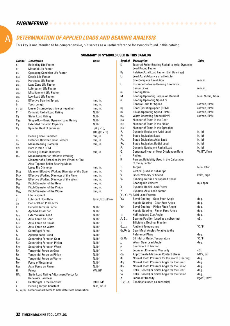
ENGINEERING
A
32 TIMKEN MACHINE TOOL CATALOG
DETERMINATION OF APPLIED LOADS AND BEARING ANALYSISThis key is not intended to be comprehensive, but serves as a useful reference for symbols found in this catalog.
Symbol Description Unitsa1 Reliability Life Factor a2 Material Life Factor a3 Operating Condition Life Factor a3d Debris Life Factor a3h Hardness Life Factor a3k Load Zone Life Factor a3l Lubrication Life Factor a3m Misalignment Life Factor a3p Low Load Life Factor ae Effective Bearing Spread mm, in.b Tooth Length mm, in.c1, c2 Linear Distance (positive or negative) mm, in.C Dynamic Radial Load Rating N, lbfC0 Static Load Rating N, lbfC90 Single-Row Basic Dynamic Load Rating N, lbfCe Extended Dynamic Capacity N, lbfCp Specific Heat of Lubricant J/(kg -˚C), BTU/(lb x ˚F)d Bearing Bore Diameter mm, in.dc Distance Between Gear Centers mm, in.dm Mean Bearing Diameter mm, in.dN Bore in mm • RPM D Bearing Outside Diameter mm, in.Dm Mean Diameter or Effective Working Diameter of a Sprocket, Pulley, Wheel or Tire Also, Tapered Roller Bearing Mean Large Rib Diameter mm, in.DmG Mean or Effective Working Diameter of the Gear mm, in.DmP Effective Working Diameter of the Pinion mm, in.DmW Effective Working Diameter of the Worm mm, in.DpG Pitch Diameter of the Gear mm, in.DpP Pitch Diameter of the Pinion mm, in.DpW Pitch Diameter of the Worm mm, in.e Life Exponent
Lubricant Flow Rate L/min, U.S. pt/minB Belt or Chain Pull Factor
F General Term for Force N, lbfFa Applied Axial Load N, lbfFae External Axial Load N, lbfFaG Axial Force on Gear N, lbfFaP Axial Force on Pinion N, lbfFaW Axial Force on Worm N, lbfFc Centrifugal Force N, lbfFr Applied Radial Load N, lbfFsG Separating Force on Gear N, lbfFsP Separating Force on Pinion N, lbfFsW Separating Force on Worm N, lbfFtG Tangential Force on Gear N, lbfFtP Tangential Force on Pinion N, lbfFtW Tangential Force on Worm N, lbfFW Force of Unbalance N, lbfFΦP Axial Force on Pinion N, lbfH Power kW, HPHFs Static Load Rating Adjustment Factor for Raceway Hardness k Centrifugal Force Constant lbf/RPM2
k1 Bearing Torque Constant N-m, lbf-in.k4, k5, k6 Dimensional Factor to Calculate Heat Generation
Symbol Description UnitsK Tapered Roller Bearing Radial-to-Axial Dynamic Load Rating FactorKT Relative Axial Load Factor (Ball Bearings)LH Lead Axial Advance of a Helix for One Complete Revolution mm, in.L Distance Between Bearing Geometric Center Lines mm, in.m Gearing Ratio M Bearing Operating Torque or Moment N-m, N-mm, lbf-in.n Bearing Operating Speed or General Term for Speed rot/min, RPMnG Gear Operating Speed (RPM) rot/min, RPMnP Pinion Operating Speed (RPM) rot/min, RPMnW Worm Operating Speed (RPM) rot/min, RPMNG Number of Teeth in the Gear NP Number of Teeth in the Pinion NS Number of Teeth in the Sprocket Pa Dynamic Equivalent Axial Load N, lbf P0 Static Equivalent Load N, lbfP0a Static Equivalent Axial Load N, lbfP0r Static Equivalent Radial Load N, lbfPr Dynamic Equivalent Radial Load N, lbfQ Generated Heat or Heat Dissipation Rate W, BTU/minr RadiusR Percent Reliability Used in the Calculation of the a1 FactorT Torque N-m, lbf-in.v Vertical (used as subscript) V Linear Velocity or Speed km/h, mphVr Rubbing, Surface or Tapered Roller Bearing Rib Velocity m/s, fpmX Dynamic Radial Load Factor Y Dynamic Axial Load FactorY1, Y2, Y3 Axial Load FactorsΥG Bevel Gearing – Gear Pitch Angle deg. Hypoid Gearing – Gear Root Angle deg.ΥP Bevel Gearing – Pinion Pitch Angle deg. Hypoid Gearing – Pinion Face Angle deg. Half Included Cup Angle deg.A, B... Bearing Position (used as a subscript) cStη Efficiency, Decimal Fraction θambt Ambient Temperature ˚C, ˚Fθ1, θ2, θ3 Gear Mesh Angles Relative to the Reference Plane deg.θi, θo Oil Inlet or Outlet Temperature ˚C, ˚Fλ Worm Gear Lead Angle deg.μ Coefficient of Friction v Lubricant Kinematic Viscosity cStσ0 Approximate Maximum Contact Stress MPa, psiΦ Normal Tooth Pressure for the Worm (Gearing) deg.ΦG Normal Tooth Pressure Angle for the Gear deg.ΦP Normal Tooth Pressure Angle for the Pinion deg.ΨG Helix (Helical) or Spiral Angle for the Gear deg.ΨP Helix (Helical) or Spiral Angle for the Pinion deg.ρ Lubricant Density kg/m3, lb/ft3
1, 2, ...n Conditions (used as subscript)
SUMMARY OF SYMBOLS USED IN THIS CATALOG
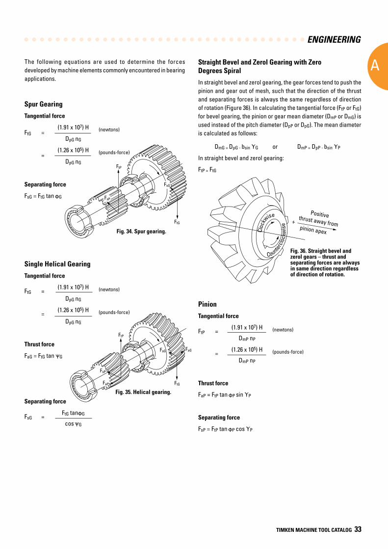
ENGINEERING
A
TIMKEN MACHINE TOOL CATALOG 33
FsP
FtP
FtG
FsG
FaP
FaG
FsP
FtP
FtG
FsG
Positive thrust away frompinion apex
+
Cloc
kwise
C o unterc
lock
wis
e
DETERMINATION OF APPLIED LOADS
Spur Gearing
Tangential force
FtG = (1.91 x 10⁷) H (newtons)
DpG nG
= (1.26 x 10⁵) H (pounds-force)
DpG nG
Separating force
FsG = FtG tan ΦG
Single Helical Gearing
Tangential force
FtG = (1.91 x 10⁷) H (newtons)
DpG nG
= (1.26 x 10⁵) H (pounds-force)
DpG nG
Thrust force
FaG = FtG tan ΨG
Separating force
FsG = FtG tanΦG
cos ΨG
Fig. 34. Spur gearing.
Fig. 35. Helical gearing .
Straight Bevel and Zerol Gearing with Zero Degrees Spiral
In straight bevel and zerol gearing, the gear forces tend to push the pinion and gear out of mesh, such that the direction of the thrust and separating forces is always the same regardless of direction of rotation (Figure 36). In calculating the tangential force (FtP or FtG) for bevel gearing, the pinion or gear mean diameter (DmP or DmG) is used instead of the pitch diameter (DpP or DpG). The mean diameter is calculated as follows:
DmG = DpG - bsin ΥG or DmP = DpP - bsin ΥP
In straight bevel and zerol gearing:
FtP = FtG
Pinion
Tangential force
FtP = (1.91 x 10⁷) H (newtons)
DmP nP
= (1.26 x 10⁵) H (pounds-force)
DmP nP
Thrust force
FaP = FtP tan ΦP sin ΥP
Separating force
FsP = FtP tan ΦP cos ΥP
The following equations are used to determine the forces developed by machine elements commonly encountered in bearing applications.
Fig. 36. Straight bevel and zerol gears – thrust and separating forces are always in same direction regardless of direction of rotation.
Positive thrust away frompinion apexCl
ockw
ise
Countercl
ockw
ise
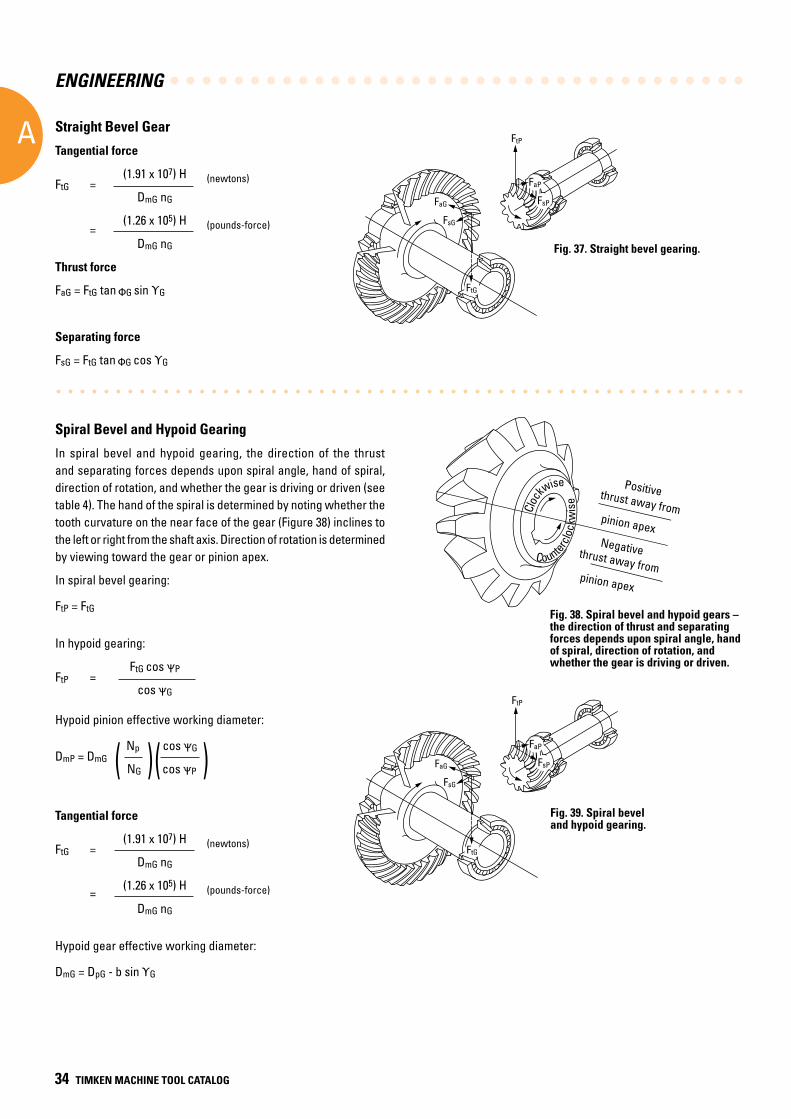
ENGINEERING
A
34 TIMKEN MACHINE TOOL CATALOG
FaG
FsG
FtG
FtP
FaP
FsP
FaG
FsG
FtG
FtP
FaP
FsP
Cloc
kwise
C o u nterc
lock
wis
e
Positive thrust away frompinion apex
+
Negative thrust towardpinion apex
–
Straight Bevel Gear
Tangential force
FtG = (1.91 x 10⁷) H (newtons)
DmG nG
= (1.26 x 10⁵) H (pounds-force)
DmG nG
Thrust force
FaG = FtG tan ΦG sin ΥG
Separating force
FsG = FtG tan ΦG cos ΥG
Spiral Bevel and Hypoid Gearing
In spiral bevel and hypoid gearing, the direction of the thrust and separating forces depends upon spiral angle, hand of spiral, direction of rotation, and whether the gear is driving or driven (see table 4). The hand of the spiral is determined by noting whether the tooth curvature on the near face of the gear (Figure 38) inclines to the left or right from the shaft axis. Direction of rotation is determined by viewing toward the gear or pinion apex.
In spiral bevel gearing:
FtP = FtG
In hypoid gearing:
FtP = FtG cos ΨP
cos ΨG
Hypoid pinion effective working diameter:
DmP = DmG Np cos ΨG
NG cos ΨP
Tangential force
FtG = (1.91 x 10⁷) H (newtons)
DmG nG
= (1.26 x 10⁵) H (pounds-force)
DmG nG
Hypoid gear effective working diameter:
DmG = DpG - b sin ΥG
( )
Fig. 37. Straight bevel gearing.
Fig. 39. Spiral bevel and hypoid gearing .
Fig. 38. Spiral bevel and hypoid gears – the direction of thrust and separating forces depends upon spiral angle, hand of spiral, direction of rotation, and whether the gear is driving or driven.
( )
Positive thrust away from
Negative thrust away from
pinion apex
pinion apex
Cloc
kwise
Countercl
ockw
ise
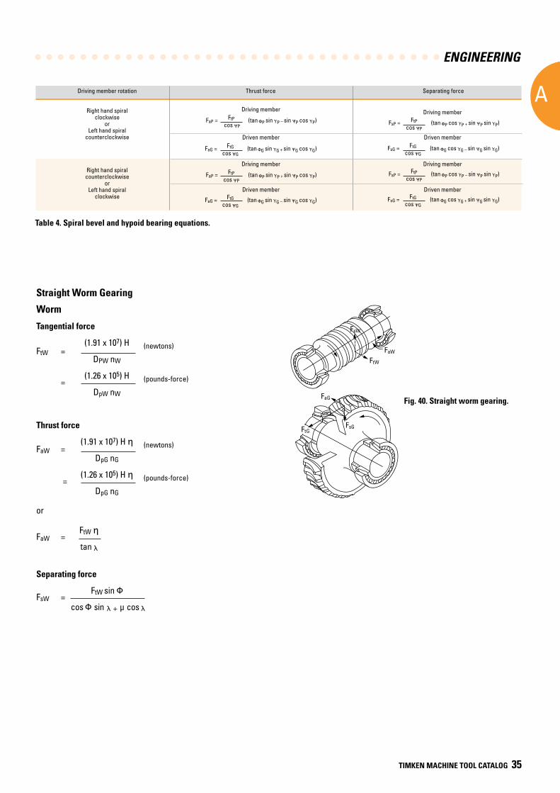
ENGINEERING
A
TIMKEN MACHINE TOOL CATALOG 35
Straight Worm Gearing
Worm
Tangential force
FtW = (1.91 x 10⁷) H (newtons)
DPW nW
= (1.26 x 10⁵) H (pounds-force)
DpW nW
Thrust force
FaW = (1.91 x 10⁷) H η (newtons)
DpG nG
= (1.26 x 10⁵) H η (pounds-force)
DpG nG
or
FaW = FtW η
tan λ
Separating force
FsW = FtW sin Φ
cos Φ sin λ + μ cos λ
Fig. 40. Straight worm gearing .
Table 4. Spiral bevel and hypoid bearing equations.
Driving member rotation Thrust force Separating force Right hand spiral clockwise or Left hand spiral counterclockwise
Right hand spiral counterclockwise or Left hand spiral clockwise
FaP = FtP (tan ΦP sin ΥP – sin ΨP cos ΥP) cos ΨP
Driving member
FaG = FtG (tan ΦG sin ΥG + sin ΨG cos ΥG) cos ΨG
Driven member
FaP = FtP (tan ΦP sin ΥP + sin ΨP cos ΥP) cos ΨP
Driving member
Driven member
FaG = FtG (tan ΦG sin ΥG – sin ΨG cos ΥG) cos ΨG
Driving member
Driven member
Driving member
Driven member
FsP = FtP (tan ΦP cos ΥP + sin ΨP sin ΥP) cos ΨP
FsG = FtG (tan ΦG cos ΥG – sin ΨG sin ΥG) cos ΨG
FsP = FtP (tan ΦP cos ΥP – sin ΨP sin ΥP) cos ΨP
FsG = FtG (tan ΦG cos ΥG + sin ΨG sin ΥG) cos ΨG
FtW
FsW
FaW
FaG
FsGFtG
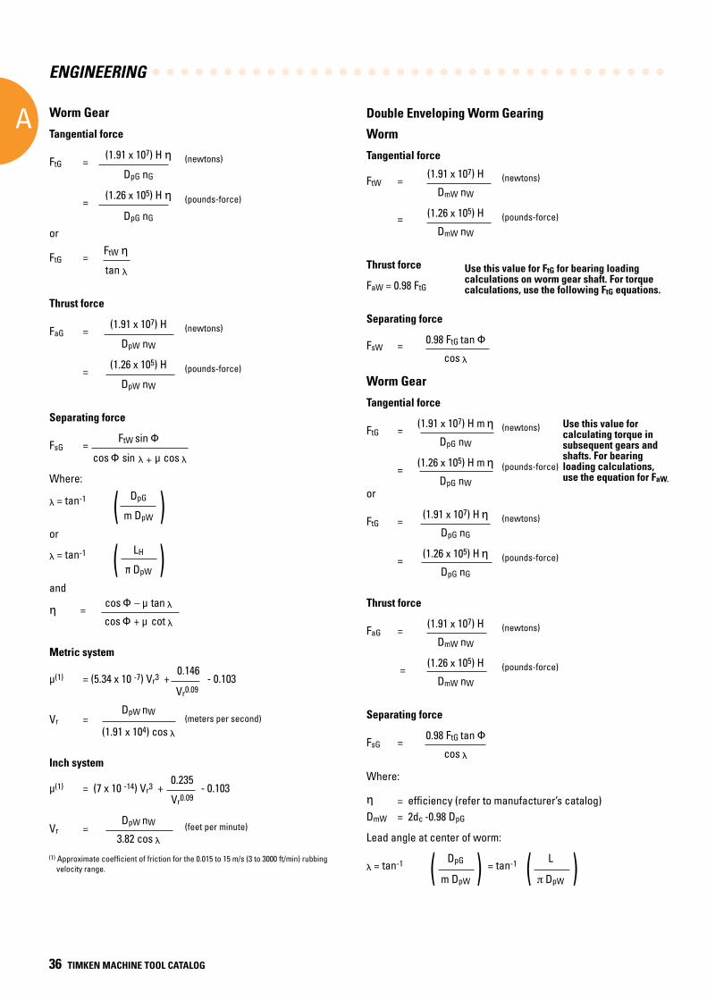
ENGINEERING
A
36 TIMKEN MACHINE TOOL CATALOG
( )( )
Worm Gear
Tangential force
FtG = (1.91 x 10⁷) H η (newtons)
DpG nG
= (1.26 x 10⁵) H η (pounds-force)
DpG nG
or
FtG = FtW η
tan λ
Thrust force
FaG = (1.91 x 10⁷) H (newtons)
DpW nW
= (1.26 x 10⁵) H (pounds-force)
DpW nW
Separating force
FsG = FtW sin Φ
cos Φ sin λ + μ cos λ
Where:
λ = tan-1 DpG m DpW
or
λ = tan-1 LH π DpW
and
η = cos Φ – μ tan λ
cos Φ + μ cot λ
Metric system
μ(1) = (5.34 x 10 -7) Vr3 + 0.146 - 0.103 Vr0.09
Vr = DpW nW (meters per second)
(1.91 x 10⁴) cos λ
Inch system
μ(1) = (7 x 10 -14) Vr3 + 0.235 - 0.103 Vr0.09
Vr = DpW nW (feet per minute) 3.82 cos λ(1) Approximate coefficient of friction for the 0.015 to 15 m/s (3 to 3000 ft/min) rubbing velocity range.
Double Enveloping Worm Gearing
Worm
Tangential force
FtW = (1.91 x 10⁷) H (newtons)
DmW nW
= (1.26 x 10⁵) H (pounds-force)
DmW nW
Thrust force
FaW = 0.98 FtG
Separating force
FsW = 0.98 FtG tan Φ
cos λ
Worm Gear
Tangential force
FtG = (1.91 x 10⁷) H m η (newtons)
DpG nW
= (1.26 x 10⁵) H m η (pounds-force)
DpG nWor
FtG = (1.91 x 10⁷) H η (newtons)
DpG nG
= (1.26 x 10⁵) H η (pounds-force)
DpG nG
Thrust force
FaG = (1.91 x 10⁷) H (newtons)
DmW nW
= (1.26 x 10⁵) H (pounds-force)
DmW nW
Separating force
FsG = 0.98 FtG tan Φ
cos λ
Where:
η = efficiency (refer to manufacturer’s catalog)DmW = 2dc -0.98 DpG
Lead angle at center of worm:
λ = tan-1 DpG = tan-1 L
m DpW DpW
Use this value for FtG for bearing loading calculations on worm gear shaft. For torque calculations, use the following FtG equations.
Use this value for calculating torque in subsequent gears and shafts. For bearing loading calculations, use the equation for FaW.
( ) ( )
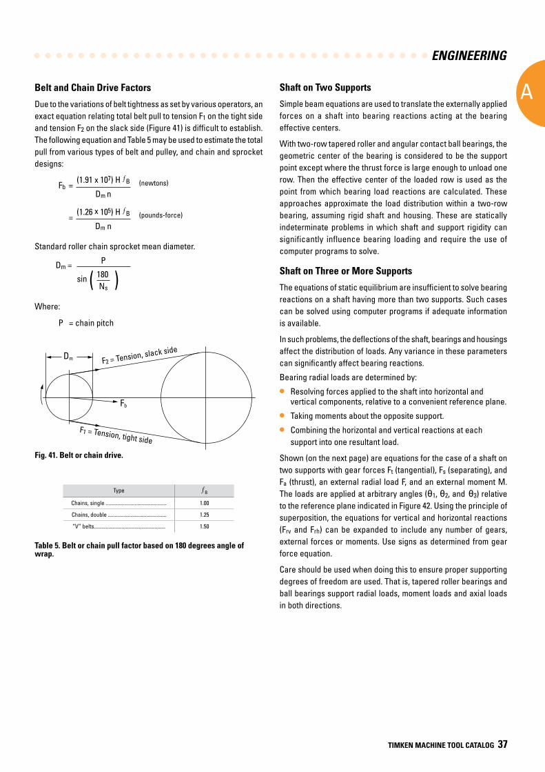
ENGINEERING
A
TIMKEN MACHINE TOOL CATALOG 37
Type B
Chains, single .............................................. 1.00
Chains, double ............................................ 1.25
“V” belts...................................................... 1.50
Table 5. Belt or chain pull factor based on 180 degrees angle of wrap.
( )
Fig. 9-8Fig. 41. Belt or chain drive.
Belt and Chain Drive Factors
Due to the variations of belt tightness as set by various operators, an exact equation relating total belt pull to tension F1 on the tight side and tension F2 on the slack side (Figure 41) is difficult to establish. The following equation and Table 5 may be used to estimate the total pull from various types of belt and pulley, and chain and sprocket designs:
Fb = (1.91 x 10⁷) H B (newtons)
Dm n
= (1.26 x 10⁵) H B (pounds-force)
Dm n
Standard roller chain sprocket mean diameter.
Dm = P sin 180 Ns
Where:
P = chain pitch
Shaft on Two Supports
Simple beam equations are used to translate the externally applied forces on a shaft into bearing reactions acting at the bearing effective centers.
With two-row tapered roller and angular contact ball bearings, the geometric center of the bearing is considered to be the support point except where the thrust force is large enough to unload one row. Then the effective center of the loaded row is used as the point from which bearing load reactions are calculated. These approaches approximate the load distribution within a two-row bearing, assuming rigid shaft and housing. These are statically indeterminate problems in which shaft and support rigidity can significantly influence bearing loading and require the use of computer programs to solve.
Shaft on Three or More Supports
The equations of static equilibrium are insufficient to solve bearing reactions on a shaft having more than two supports. Such cases can be solved using computer programs if adequate information is available.
In such problems, the deflections of the shaft, bearings and housings affect the distribution of loads. Any variance in these parameters can significantly affect bearing reactions.
Bearing radial loads are determined by:
• Resolving forces applied to the shaft into horizontal and vertical components, relative to a convenient reference plane.
• Taking moments about the opposite support.
• Combining the horizontal and vertical reactions at each support into one resultant load.
Shown (on the next page) are equations for the case of a shaft on two supports with gear forces Ft (tangential), Fs (separating), and Fa (thrust), an external radial load F, and an external moment M. The loads are applied at arbitrary angles (θ1, θ2, and θ3) relative to the reference plane indicated in Figure 42. Using the principle of superposition, the equations for vertical and horizontal reactions (Frv and Frh) can be expanded to include any number of gears, external forces or moments. Use signs as determined from gear force equation.
Care should be used when doing this to ensure proper supporting degrees of freedom are used. That is, tapered roller bearings and ball bearings support radial loads, moment loads and axial loads in both directions.
Dm
Fb
F2 = Tension, slack side
F1 = Tension, tight side
F2 = Tension, slack side
F1 = Tension, tight side
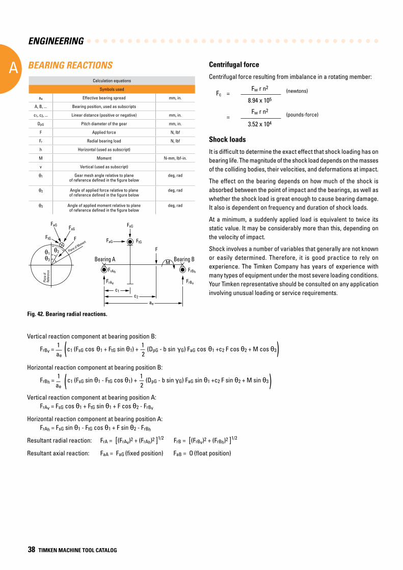
ENGINEERING
A
38 TIMKEN MACHINE TOOL CATALOG
Vertical reaction component at bearing position B:
FrBv = 1 c1 (FsG cos θ1 + FtG sin θ1) + 1 (DpG - b sin γG) FaG cos θ1 +c2 F cos θ2 + M cos θ3
ae 2
Horizontal reaction component at bearing position B:
FrBh = 1 c1 (FsG sin θ1 - FtG cos θ1) + 1 (DpG - b sin γG) FaG sin θ1 +c2 F sin θ2 + M sin θ3 ae 2
Vertical reaction component at bearing position A: FrAv = FsG cos θ1 + FtG sin θ1 + F cos θ2 - FrBv
Horizontal reaction component at bearing position A: FrAh = FsG sin θ1 - FtG cos θ1 + F sin θ2 - FrBh
Resultant radial reaction: FrA = [(FrAv)2 + (FrAh)2 ]1/2 FrB = [(FrBv)2 + (FrBh)2 ]1/2
Resultant axial reaction: FaA = FaG (fixed position) FaB = O (float position)
(
(
(
(
Calculation equations
Symbols used
ae Effective bearing spread mm, in.
A, B, ... Bearing position, used as subscripts
c1, c2, ... Linear distance (positive or negative) mm, in.
DpG Pitch diameter of the gear mm, in.
F Applied force N, lbf
Fr Radial bearing load N, lbf
h Horizontal (used as subscript)
M Moment N-mm, lbf-in.
v Vertical (used as subscript)
θ1 Gear mesh angle relative to plane of reference defined in the figure below
deg, rad
θ2 Angle of applied force relative to plane of reference defined in the figure below
deg, rad
θ3 Angle of applied moment relative to plane of reference defined in the figure below
deg, rad
Fig. 42. Bearing radial reactions.
Shock loads
It is difficult to determine the exact effect that shock loading has on bearing life. The magnitude of the shock load depends on the masses of the colliding bodies, their velocities, and deformations at impact.
The effect on the bearing depends on how much of the shock is absorbed between the point of impact and the bearings, as well as whether the shock load is great enough to cause bearing damage. It also is dependent on frequency and duration of shock loads.
At a minimum, a suddenly applied load is equivalent to twice its static value. It may be considerably more than this, depending on the velocity of impact.
Shock involves a number of variables that generally are not known or easily determined. Therefore, it is good practice to rely on experience. The Timken Company has years of experience with many types of equipment under the most severe loading conditions. Your Timken representative should be consulted on any application involving unusual loading or service requirements.
Centrifugal force
Centrifugal force resulting from imbalance in a rotating member:
Fc = Fw r n2 (newtons)
8.94 x 105
= Fw r n2 (pounds-force)
3.52 x 10⁴
BEARING REACTIONS
θ3
θ1θ2
Plan
e of
Refe
renc
e
Plane of MomentF
FsGFaG
FtG FaG
FsG
FtG
F
c1c2
ae
Bearing A Bearing B
FrAh
FrAv
FrBh
FrBv
M
Plane of Moment
Plan
e of
Refe
renc
e
Bearing A Bearing B
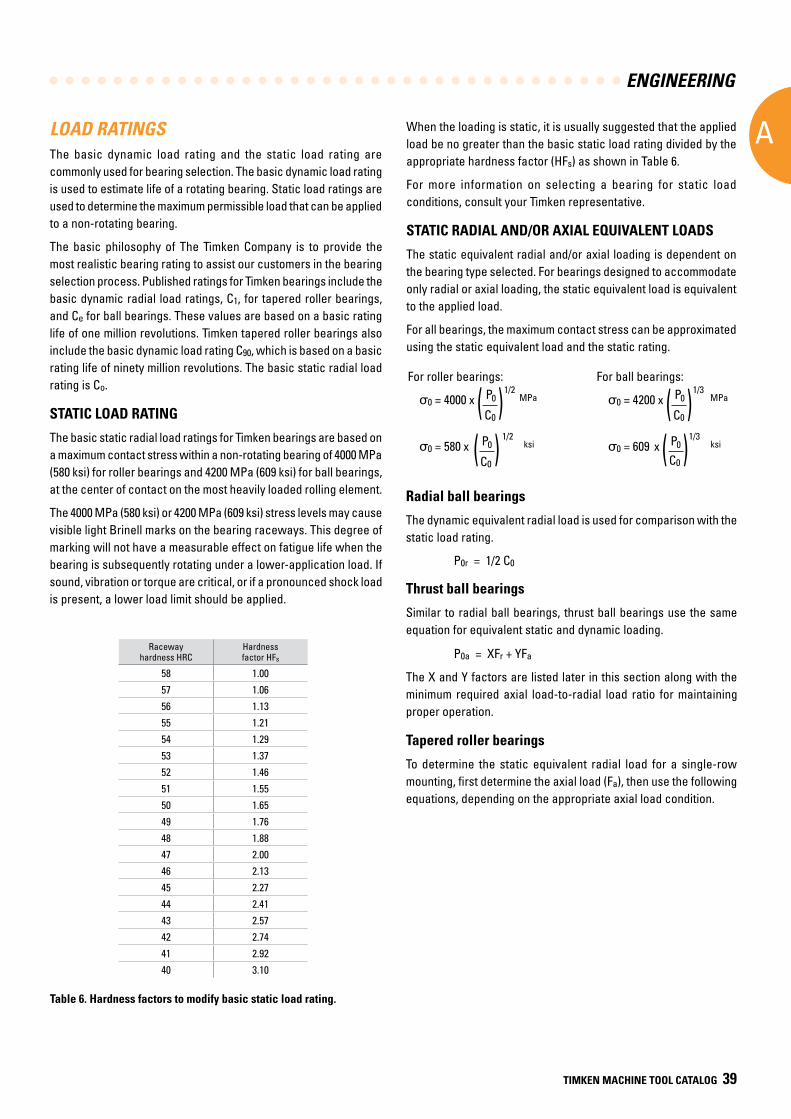
ENGINEERING
A
TIMKEN MACHINE TOOL CATALOG 39
LOAD RATINGSThe basic dynamic load rating and the static load rating are commonly used for bearing selection. The basic dynamic load rating is used to estimate life of a rotating bearing. Static load ratings are used to determine the maximum permissible load that can be applied to a non-rotating bearing.
The basic philosophy of The Timken Company is to provide the most realistic bearing rating to assist our customers in the bearing selection process. Published ratings for Timken bearings include the basic dynamic radial load ratings, C1, for tapered roller bearings, and Ce for ball bearings. These values are based on a basic rating life of one million revolutions. Timken tapered roller bearings also include the basic dynamic load rating C90, which is based on a basic rating life of ninety million revolutions. The basic static radial load rating is Co.
STATIC LOAD RATING
The basic static radial load ratings for Timken bearings are based on a maximum contact stress within a non-rotating bearing of 4000 MPa (580 ksi) for roller bearings and 4200 MPa (609 ksi) for ball bearings, at the center of contact on the most heavily loaded rolling element.
The 4000 MPa (580 ksi) or 4200 MPa (609 ksi) stress levels may cause visible light Brinell marks on the bearing raceways. This degree of marking will not have a measurable effect on fatigue life when the bearing is subsequently rotating under a lower-application load. If sound, vibration or torque are critical, or if a pronounced shock load is present, a lower load limit should be applied.
Radial ball bearings
The dynamic equivalent radial load is used for comparison with the static load rating.
P0r = 1/2 C0
Thrust ball bearings
Similar to radial ball bearings, thrust ball bearings use the same equation for equivalent static and dynamic loading.
P0a = XFr + YFa
The X and Y factors are listed later in this section along with the minimum required axial load-to-radial load ratio for maintaining proper operation.
Tapered roller bearings
To determine the static equivalent radial load for a single-row mounting, first determine the axial load (Fa), then use the following equations, depending on the appropriate axial load condition.
For ball bearings:
σ0 = 4200 x P0 1/3
MPa
C0
σ0 = 609 x P0 1/3
ksi C0
For roller bearings:
σ0 = 4000 x P0 1/2
MPa
C0
σ0 = 580 x P0 1/2
ksi C0
( )( )
( )( )
Racewayhardness HRC
Hardnessfactor HFs
58 1.00
57 1.06
56 1.13
55 1.21
54 1.29
53 1.37
52 1.46
51 1.55
50 1.65
49 1.76
48 1.88
47 2.00
46 2.13
45 2.27
44 2.41
43 2.57
42 2.74
41 2.92
40 3.10
Table 6. Hardness factors to modify basic static load rating.
When the loading is static, it is usually suggested that the applied load be no greater than the basic static load rating divided by the appropriate hardness factor (HFs) as shown in Table 6.
For more information on selecting a bearing for static load conditions, consult your Timken representative.
STATIC RADIAL AND/OR AXIAL EQUIVALENT LOADS
The static equivalent radial and/or axial loading is dependent on the bearing type selected. For bearings designed to accommodate only radial or axial loading, the static equivalent load is equivalent to the applied load.
For all bearings, the maximum contact stress can be approximated using the static equivalent load and the static rating.
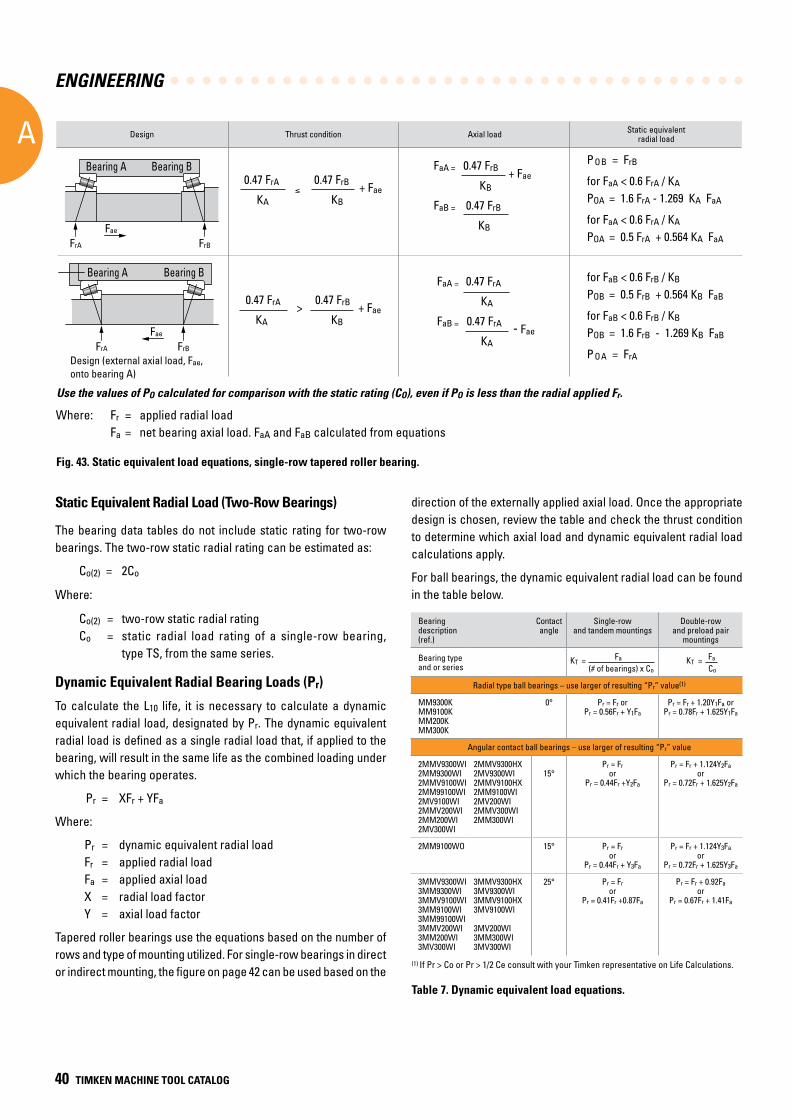
ENGINEERING
A
40 TIMKEN MACHINE TOOL CATALOG
FrA FrB
Fae
FrA FrB
Fae
Design Thrust condition Axial load Static equivalent radial load
0.47 FrA ≤
0.47 FrB + Fae KA KB
FaA = 0.47 FrB + Fae KB
FaB = 0.47 FrB
KB
FaA = 0.47 FrA
KA
FaB = 0.47 FrA - Fae KA
0.47 FrA > 0.47 FrB + Fae
KA KB
P OB = FrB
for FaA < 0.6 FrA / KA
POA = 1.6 FrA - 1.269 KA FaA
for FaA < 0.6 FrA / KA
POA = 0.5 FrA + 0.564 KA FaA
Design (external axial load, Fae, onto bearing A)
for FaB < 0.6 FrB / KB
POB = 0.5 FrB + 0.564 KB FaB
for FaB < 0.6 FrB / KB
POB = 1.6 FrB - 1.269 KB FaB
P OA = FrA
Use the values of PO calculated for comparison with the static rating (CO), even if PO is less than the radial applied Fr.
Fig. 43. Static equivalent load equations, single-row tapered roller bearing.
Static Equivalent Radial Load (Two-Row Bearings)
The bearing data tables do not include static rating for two-row bearings. The two-row static radial rating can be estimated as:
Co(2) = 2Co
Where:
Co(2) = two-row static radial rating Co = static radial load rating of a single-row bearing, type TS, from the same series.
Dynamic Equivalent Radial Bearing Loads (Pr)
To calculate the L10 life, it is necessary to calculate a dynamic equivalent radial load, designated by Pr. The dynamic equivalent radial load is defined as a single radial load that, if applied to the bearing, will result in the same life as the combined loading under which the bearing operates.
Pr = XFr + YFa
Where:
Pr = dynamic equivalent radial load Fr = applied radial load Fa = applied axial load X = radial load factor Y = axial load factor
Tapered roller bearings use the equations based on the number of rows and type of mounting utilized. For single-row bearings in direct or indirect mounting, the figure on page 42 can be used based on the
Bearingdescription (ref.)
Contactangle
Single-row and tandem mountings
Double-rowand preload pair
mountings
Bearing type and or series
KT = Fa (# of bearings) x Co
KT = Fa
Co
Radial type ball bearings – use larger of resulting “Pr” value(1)
MM9300KMM9100KMM200KMM300K
0° Pr = Fr orPr = 0.56Fr + Y1Fa
Pr = Fr + 1.20Y1Fa orPr = 0.78Fr + 1.625Y1Fa
Angular contact ball bearings – use larger of resulting “Pr” value
2MMV9300WI 2MM9300WI 2MMV9100WI 2MM99100WI2MV9100WI2MMV200WI 2MM200WI 2MV300WI
2MMV9300HX2MV9300WI2MMV9100HX2MM9100WI2MV200WI2MMV300WI2MM300WI
15°
Pr = Fr or
Pr = 0.44Fr +Y2Fa
Pr = Fr + 1.124Y2Faor
Pr = 0.72Fr + 1.625Y2Fa
2MM9100WO 15° Pr = Fr or
Pr = 0.44Fr + Y3Fa
Pr = Fr + 1.124Y3Faor
Pr = 0.72Fr + 1.625Y3Fa
3MMV9300WI3MM9300WI 3MMV9100WI3MM9100WI 3MM99100WI3MMV200WI 3MM200WI 3MV300WI
3MMV9300HX3MV9300WI3MMV9100HX3MV9100WI 3MV200WI3MM300WI3MV300WI
25° Pr = Fror
Pr = 0.41Fr +0.87Fa
Pr = Fr + 0.92Faor
Pr = 0.67Fr + 1.41Fa
direction of the externally applied axial load. Once the appropriate design is chosen, review the table and check the thrust condition to determine which axial load and dynamic equivalent radial load calculations apply.
For ball bearings, the dynamic equivalent radial load can be found in the table below.
Where: Fr = applied radial load Fa = net bearing axial load. FaA and FaB calculated from equations
(1) If Pr > Co or Pr > 1/2 Ce consult with your Timken representative on Life Calculations.
Table 7. Dynamic equivalent load equations.
Bearing A
Bearing A
Bearing B
Bearing B
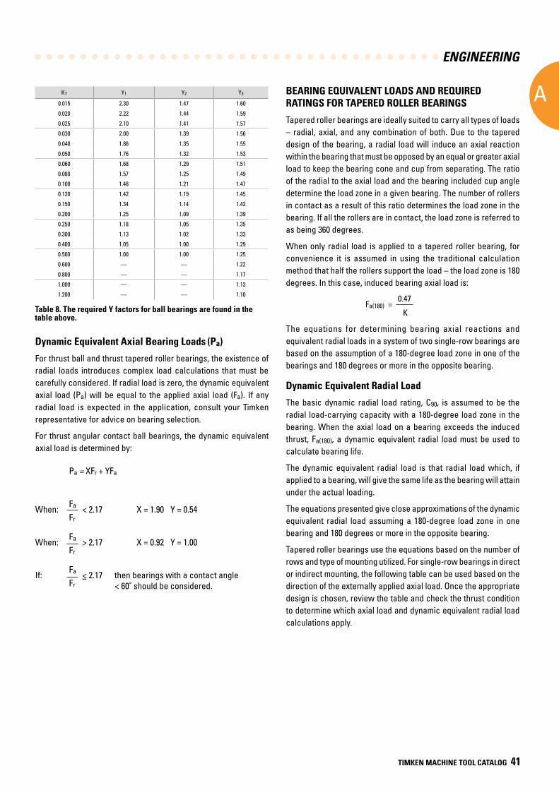
ENGINEERING
A
TIMKEN MACHINE TOOL CATALOG 41
Design Thrust condition Axial load Static equivalent radial load
KT Y1 Y2 Y3
0.015 2.30 1.47 1.60
0.020 2.22 1.44 1.59
0.025 2.10 1.41 1.57
0.030 2.00 1.39 1.56
0.040 1.86 1.35 1.55
0.050 1.76 1.32 1.53
0.060 1.68 1.29 1.51
0.080 1.57 1.25 1.49
0.100 1.48 1.21 1.47
0.120 1.42 1.19 1.45
0.150 1.34 1.14 1.42
0.200 1.25 1.09 1.39
0.250 1.18 1.05 1.35
0.300 1.13 1.02 1.33
0.400 1.05 1.00 1.29
0.500 1.00 1.00 1.25
0.600 — — 1.22
0.800 — — 1.17
1.000 — — 1.13
1.200 — — 1.10
Dynamic Equivalent Axial Bearing Loads (Pa)
For thrust ball and thrust tapered roller bearings, the existence of radial loads introduces complex load calculations that must be carefully considered. If radial load is zero, the dynamic equivalent axial load (Pa) will be equal to the applied axial load (Fa). If any radial load is expected in the application, consult your Timken representative for advice on bearing selection.
For thrust angular contact ball bearings, the dynamic equivalent axial load is determined by:
Table 8. The required Y factors for ball bearings are found in the table above.
BEARING EQUIVALENT LOADS AND REQUIRED RATINGS FOR TAPERED ROLLER BEARINGS
Tapered roller bearings are ideally suited to carry all types of loads – radial, axial, and any combination of both. Due to the tapered design of the bearing, a radial load will induce an axial reaction within the bearing that must be opposed by an equal or greater axial load to keep the bearing cone and cup from separating. The ratio of the radial to the axial load and the bearing included cup angle determine the load zone in a given bearing. The number of rollers in contact as a result of this ratio determines the load zone in the bearing. If all the rollers are in contact, the load zone is referred to as being 360 degrees.
When only radial load is applied to a tapered roller bearing, for convenience it is assumed in using the traditional calculation method that half the rollers support the load – the load zone is 180 degrees. In this case, induced bearing axial load is:
The equations for determining bearing axial reactions and equivalent radial loads in a system of two single-row bearings are based on the assumption of a 180-degree load zone in one of the bearings and 180 degrees or more in the opposite bearing.
Dynamic Equivalent Radial Load
The basic dynamic radial load rating, C90, is assumed to be the radial load-carrying capacity with a 180-degree load zone in the bearing. When the axial load on a bearing exceeds the induced thrust, Fa(180), a dynamic equivalent radial load must be used to calculate bearing life.
The dynamic equivalent radial load is that radial load which, if applied to a bearing, will give the same life as the bearing will attain under the actual loading.
The equations presented give close approximations of the dynamic equivalent radial load assuming a 180-degree load zone in one bearing and 180 degrees or more in the opposite bearing.
Tapered roller bearings use the equations based on the number of rows and type of mounting utilized. For single-row bearings in direct or indirect mounting, the following table can be used based on the direction of the externally applied axial load. Once the appropriate design is chosen, review the table and check the thrust condition to determine which axial load and dynamic equivalent radial load calculations apply.
Fa(180) = 0.47
K
Pa = XFr + YFa
When: Fa
< 2.17 X = 1.90 Y = 0.54 Fr
When: Fa
> 2.17 X = 0.92 Y = 1.00
Fr
If: Fa
< 2.17 then bearings with a contact angle Fr
- < 60˚ should be considered.
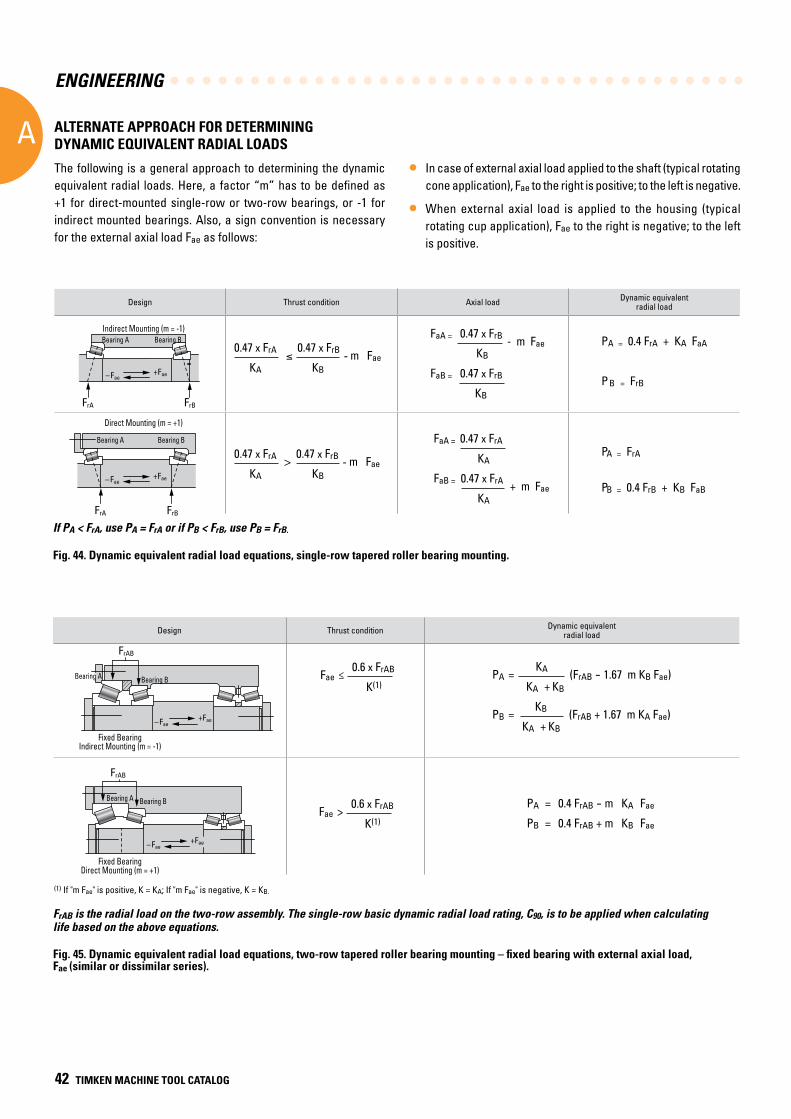
ENGINEERING
A
42 TIMKEN MACHINE TOOL CATALOG
Design Thrust condition Dynamic equivalentradial load
FrAB is the radial load on the two-row assembly. The single-row basic dynamic radial load rating, C90, is to be applied when calculating life based on the above equations.
If PA < FrA, use PA = FrA or if PB < FrB, use PB = FrB.
ALTERNATE APPROACH FOR DETERMINING DYNAMIC EQUIVALENT RADIAL LOADS
The following is a general approach to determining the dynamic equivalent radial loads. Here, a factor “m” has to be defined as +1 for direct-mounted single-row or two-row bearings, or -1 for indirect mounted bearings. Also, a sign convention is necessary for the external axial load Fae as follows:
• In case of external axial load applied to the shaft (typical rotating cone application), Fae to the right is positive; to the left is negative.
• When external axial load is applied to the housing (typical rotating cup application), Fae to the right is negative; to the left is positive.
Design Thrust condition Axial load Dynamic equivalent radial load
FaA = 0.47 x FrB - m Fae KB
FaB = 0.47 x FrB
KB
0.47 x FrA 0.47 x FrB - m Fae
KA KB
FaA = 0.47 x FrA
KA
FaB = 0.47 x FrA + m Fae KA
0.47 x FrA > 0.47 x FrB
- m Fae KA KB
PA = 0.4 FrA + KA FaA
P B = FrB
PA = FrA
PB = 0.4 FrB + KB FaB
Fae ≤
0.6 x FrAB
K(1) PA =
KA (FrAB - 1.67 m KB Fae) KA + KB
PB = KB (FrAB + 1.67 m KA Fae)
KA + KB
Fae >
0.6 x FrAB
K(1)
PA = 0.4 FrAB - m KA Fae
PB = 0.4 FrAB + m KB Fae
Fig. 44. Dynamic equivalent radial load equations, single-row tapered roller bearing mounting.
Fig. 45. Dynamic equivalent radial load equations, two-row tapered roller bearing mounting – fixed bearing with external axial load, Fae (similar or dissimilar series).
–Fae+Fae
FrA FrB
FrBFrA
–Fae+Fae
–Fae+Fae
FrAB
FrAB
–Fae+Fae
Indirect Mounting (m = -1)Bearing A Bearing B
–Fae+Fae
FrA FrB
FrBFrA
–Fae+Fae
Bearing A Bearing B
Direct Mounting (m = -1)
–Fae+Fae
FrAB
FrAB
–Fae+Fae
(1) If "m Fae" is positive, K = KA; If "m Fae" is negative, K = KB.
Bearing A
Bearing A
Bearing A
Bearing A
Bearing B
Bearing B
Bearing B
Bearing B
Indirect Mounting (m = -1)
Direct Mounting (m = +1)
Fixed BearingIndirect Mounting (m = -1)
Fixed BearingDirect Mounting (m = +1)
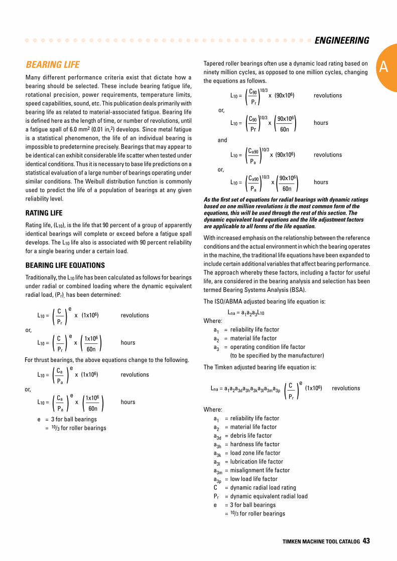
ENGINEERING
A
TIMKEN MACHINE TOOL CATALOG 43
Tapered roller bearings often use a dynamic load rating based on ninety million cycles, as opposed to one million cycles, changing the equations as follows.
As the first set of equations for radial bearings with dynamic ratings based on one million revolutions is the most common form of the equations, this will be used through the rest of this section. The dynamic equivalent load equations and the life adjustment factors are applicable to all forms of the life equation.
With increased emphasis on the relationship between the reference conditions and the actual environment in which the bearing operates in the machine, the traditional life equations have been expanded to include certain additional variables that affect bearing performance. The approach whereby these factors, including a factor for useful life, are considered in the bearing analysis and selection has been termed Bearing Systems Analysis (BSA).
The ISO/ABMA adjusted bearing life equation is:
Lna = a1a2a3L10
Where:a1 = reliability life factora2 = material life factora3 = operating condition life factor (to be specified by the manufacturer)
The Timken adjusted bearing life equation is:
( ) Lna = a1a2a3da3ha3ka3la3ma3p C e
(1x10⁶) revolutions Pr
Where:a1 = reliability life factora2 = material life factora3d = debris life factora3h = hardness life factora3k = load zone life factora3l = lubrication life factora3m = misalignment life factora3p = low load life factorC = dynamic radial load ratingPr = dynamic equivalent radial loade = 3 for ball bearings = 10/3 for roller bearings
L10 = C90 10/3
x
(90x106) revolutions Pr
or,
L10 = C90 10/3
x 90x106 hours
Pr 60n
and
L10 = Ca90 10/3
x (90x106) revolutions
Pa
or,
L10 = Ca90 10/3
x 90x106 hours
Pa 60n
( )( )
( )
( )
( )
( )
BEARING LIFE Many different performance criteria exist that dictate how a bearing should be selected. These include bearing fatigue life, rotational precision, power requirements, temperature limits, speed capabilities, sound, etc. This publication deals primarily with bearing life as related to material-associated fatigue. Bearing life is defined here as the length of time, or number of revolutions, until a fatigue spall of 6.0 mm2 (0.01 in,2) develops. Since metal fatigue is a statistical phenomenon, the life of an individual bearing is impossible to predetermine precisely. Bearings that may appear to be identical can exhibit considerable life scatter when tested under identical conditions. Thus it is necessary to base life predictions on a statistical evaluation of a large number of bearings operating under similar conditions. The Weibull distribution function is commonly used to predict the life of a population of bearings at any given reliability level.
RATING LIFE
Rating life, (L10), is the life that 90 percent of a group of apparently identical bearings will complete or exceed before a fatigue spall develops. The L10 life also is associated with 90 percent reliability for a single bearing under a certain load.
BEARING LIFE EQUATIONS
Traditionally, the L10 life has been calculated as follows for bearings under radial or combined loading where the dynamic equivalent radial load, (Pr), has been determined:
L10 = C
e x
(1x10⁶) revolutions
Pr
or,
L10 = C
e x
1x10⁶ hours
Pr 60n
For thrust bearings, the above equations change to the following.
L10 = Ca
e x
(1x10⁶) revolutions
Pa
or,
L10 = Ca
e x
1x10⁶ hours
Pa 60n
e = 3 for ball bearings = 10/3 for roller bearings
( )( )
( )
( )
( )
( )
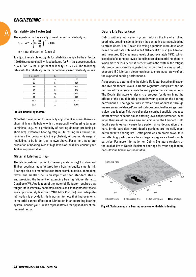
ENGINEERING
A
44 TIMKEN MACHINE TOOL CATALOG
Debris Life Factor (a3d)
Debris within a lubrication system reduces the life of a rolling bearing by creating indentations on the contacting surfaces, leading to stress risers. The Timken life rating equations were developed based on test data obtained with 0.040 mm (0.00157 in.) oil filtration and measured ISO cleanness levels of approximately 15/12, which is typical of cleanness levels found in normal industrial machinery. When more or less debris is present within the system, the fatigue life predictions can be adjusted according to the measured or expected ISO lubricant cleanness level to more accurately reflect the expected bearing performance.
As opposed to determining the debris life factor based on filtration and ISO cleanness levels, a Debris Signature Analysis™ can be performed for more accurate bearing performance predictions. The Debris Signature Analysis is a process for determining the effects of the actual debris present in your system on the bearing performance. The typical way in which this occurs is through measurements of dented/bruised surfaces on actual bearings run in a given application. This type of analysis can be beneficial because different types of debris cause differing levels of performance, even when they are of the same size and amount in the lubricant. Soft, ductile particles can cause less performance degradation than hard, brittle particles. Hard, ductile particles are typically most detrimental to bearing life. Brittle particles can break down, thus not affecting performance to as large a degree as hard ductile particles. For more information on Debris Signature Analysis or the availability of Debris Resistant bearings for your application, consult your Timken representative.
Fig. 46. Surface map of a bearing raceway with debris denting.
600
400
200
0 0
200
ISOMETRIC VIEW
400
600
μmμm
800
Core Structure 0-5% Bearing Area 5-10% Bearing Area Pits & Valleys
Reliability Life Factor (a1)
The equation for the life adjustment factor for reliability is:
a1 = 4.26 x ln 100 2/3
+ 0.05 R
ln = natural logarithm (base e)
To adjust the calculated L10 life for reliability, multiply by the a1 factor. If 90 (90 percent reliability) is substituted for R in the above equation, a1 = 1. For R = 99 (99 percent reliability), a1 = 0.25. The following table lists the reliability factor for commonly used reliability values.
Note that the equation for reliability adjustment assumes there is a short minimum life below which the probability of bearing damage is minimal (e.g., zero probability of bearing damage producing a short life). Extensive bearing fatigue life testing has shown the minimum life, below which the probability of bearing damage is negligible, to be larger than shown above. For a more accurate prediction of bearing lives at high levels of reliability, consult your Timken representative.
Material Life Factor (a2)
The life adjustment factor for bearing material (a2) for standard Timken bearings manufactured from bearing-quality steel is 1.0. Bearings also are manufactured from premium steels, containing fewer and smaller inclusion impurities than standard steels and providing the benefit of extending bearing fatigue life (e.g., DuraSpexx™). Application of the material life factor requires that fatigue life is limited by nonmetallic inclusions, that contact stresses are approximately less than 2400 MPa (350 ksi), and adequate lubrication is provided. It is important to note that improvements in material cannot offset poor lubrication in an operating bearing system. Consult your Timken representative for applicability of the material factor.
R (percent) Ln a1
90 L10 1.00
95 L5 0.64
96 L4 0.55
97 L3 0.47
98 L2 0.37
99 L1 0.25
99.5 L0.5 0.175
99.9 L0.1 0.093
Table 9. Reliability factors.
( )
ISOMETRIC VIEW
Core Structure 0-5% Bearing Area 5-10% Bearing Area Pits & Valleys
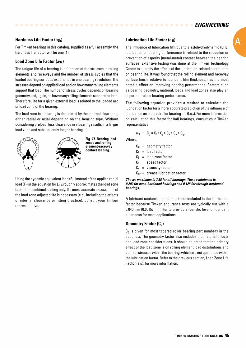
ENGINEERING
A
TIMKEN MACHINE TOOL CATALOG 45
Hardness Life Factor (a3h)
For Timken bearings in this catalog, supplied as a full assembly, the hardness life factor will be one (1).
Load Zone Life Factor (a3k)
The fatigue life of a bearing is a function of the stresses in rolling elements and raceways and the number of stress cycles that the loaded bearing surfaces experience in one bearing revolution. The stresses depend on applied load and on how many rolling elements support that load. The number of stress cycles depends on bearing geometry and, again, on how many rolling elements support the load. Therefore, life for a given external load is related to the loaded arc or load zone of the bearing.
The load zone in a bearing is dominated by the internal clearance, either radial or axial depending on the bearing type. Without considering preload, less clearance in a bearing results in a larger load zone and subsequently longer bearing life.
Using the dynamic equivalent load (Pr) instead of the applied radial load (Fr) in the equation for L10a roughly approximates the load zone factor for combined loading only. If a more accurate assessment of the load zone adjusted life is necessary (e.g., including the effects of internal clearance or fitting practice), consult your Timken representative.
Fig. 47. Bearing load zones and rolling element-raceway contact loading.
Lubrication Life Factor (a3l)
The influence of lubrication film due to elastohydrodynamic (EHL) lubrication on bearing performance is related to the reduction or prevention of asperity (metal-metal) contact between the bearing surfaces. Extensive testing was done at the Timken Technology Center to quantify the effects of the lubrication-related parameters on bearing life. It was found that the rolling element and raceway surface finish, relative to lubricant film thickness, has the most notable effect on improving bearing performance. Factors such as bearing geometry, material, loads and load zones also play an important role in bearing performance.
The following equation provides a method to calculate the lubrication factor for a more accurate prediction of the influence of lubrication on tapered roller bearing life (L10a). For more information on calculating this factor for ball bearings, consult your Timken representative.
a3l = Cg x Cl x Cj x Cs x Cv x Cgr
Where:
Cg = geometry factor Cl = load factor Cj = load zone factor Cs = speed factor Cv = viscosity factor Cgr = grease lubrication factor
The a3l maximum is 2.88 for all bearings. The a3l minimum is 0.200 for case-hardened bearings and 0.126 for through-hardened bearings.
A lubricant contamination factor is not included in the lubrication factor because Timken endurance tests are typically run with a 0.040 mm (0.00157 in.) filter to provide a realistic level of lubricant cleanness for most applications.
Geometry Factor (Cg)
Cg is given for most tapered roller bearing part numbers in the appendix. The geometry factor also includes the material effects and load zone considerations. It should be noted that the primary effect of the load zone is on rolling element load distributions and contact stresses within the bearing, which are not quantified within the lubrication factor. Refer to the previous section, Load Zone Life Factor (a3k), for more information.
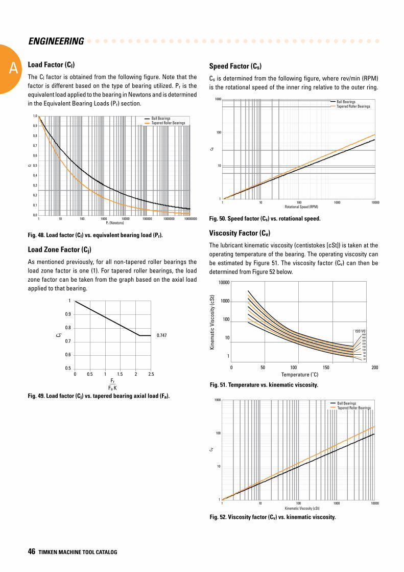
ENGINEERING
A
46 TIMKEN MACHINE TOOL CATALOG
Speed Factor (Cs)
Cs is determined from the following figure, where rev/min (RPM) is the rotational speed of the inner ring relative to the outer ring.
Fig. 50. Speed factor (Cs) vs. rotational speed.
Viscosity Factor (Cv)
The lubricant kinematic viscosity (centistokes [cSt]) is taken at the operating temperature of the bearing. The operating viscosity can be estimated by Figure 51. The viscosity factor (Cv) can then be determined from Figure 52 below.
Load Factor (Cl)
The Cl factor is obtained from the following figure. Note that the factor is different based on the type of bearing utilized. Pr is the equivalent load applied to the bearing in Newtons and is determined in the Equivalent Bearing Loads (Pr) section.
Fig. 48. Load factor (Cl) vs. equivalent bearing load (Pr).
Load Zone Factor (Cj)
As mentioned previously, for all non-tapered roller bearings the load zone factor is one (1). For tapered roller bearings, the load zone factor can be taken from the graph based on the axial load applied to that bearing.
Fig. 49. Load factor (Cj) vs. tapered bearing axial load (Fa).
1
0.9
0.8
0.7
0.6
0.50 0.5 1 1.5 2 2.5
0.747
Fr
Fa K
C j
10000
1000
100
10
1
0 50 100 150 200Temperature (˚C)
Kine
mat
ic V
isco
sity
(cSt
)
ISO VG680460320220150100684632
1
10
100
1000
1 10 100 1000 10000Rotational Speed (RPM)
C s
Ball BearingsTapered Roller Bearings
0,0
0,1
0,2
0,3
0,4
0,5
0,6
0,7
0,8
0,9
1,0
1 10 100 1000 10000 100000 1000000 10000000Pr (Newtons)
C l
Ball BearingsTapered Roller Bearings
1
10
100
1000
1 10 100 1000 10000Kinematic Viscosity (cSt)
C v
Ball BearingsTapered Roller Bearings
Fig. 51. Temperature vs. kinematic viscosity.
Fig. 52. Viscosity factor (Cv) vs. kinematic viscosity.
Ball Bearings Tapered Roller Bearings
Ball Bearings Tapered Roller Bearings
Ball Bearings Tapered Roller Bearings
Pr (Newtons)
Rotational Speed (RPM)
Kinematic Viscosity (cSt)
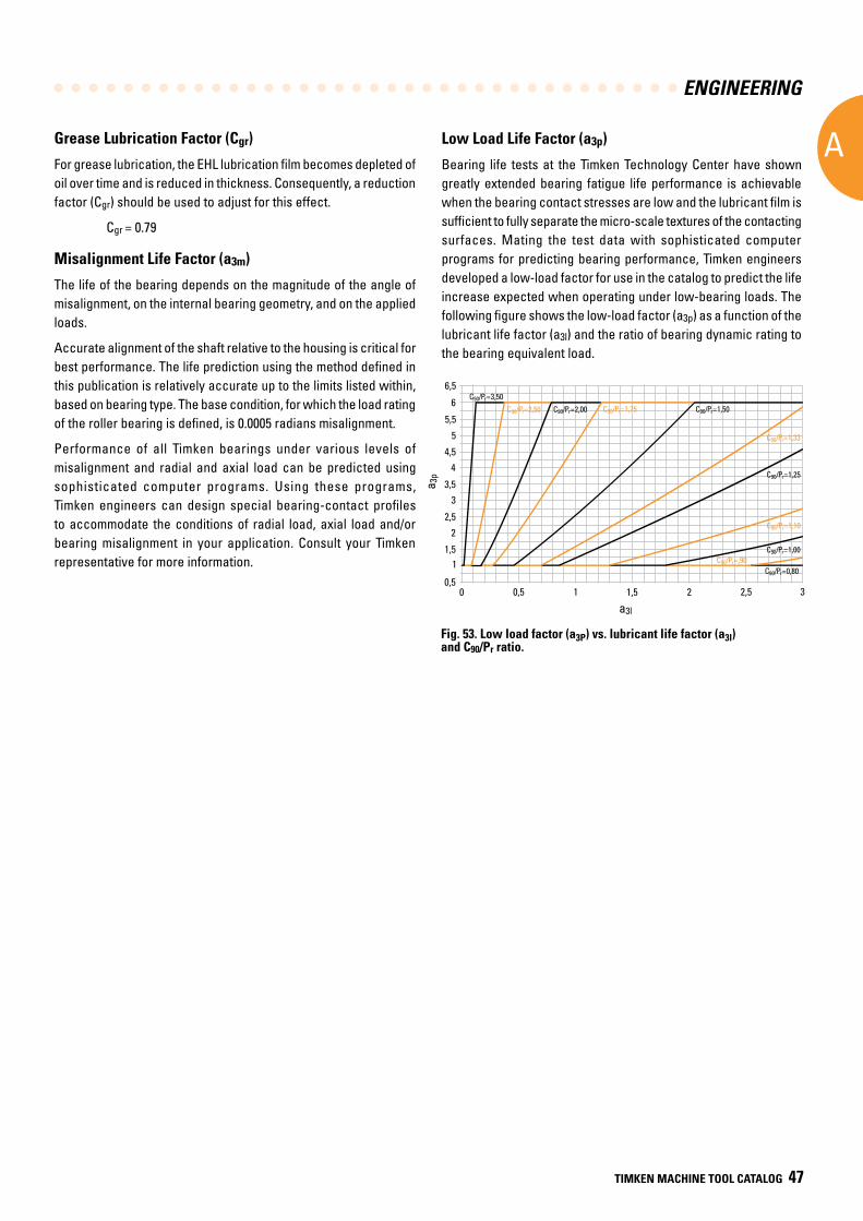
ENGINEERING
A
TIMKEN MACHINE TOOL CATALOG 47
Grease Lubrication Factor (Cgr)
For grease lubrication, the EHL lubrication film becomes depleted of oil over time and is reduced in thickness. Consequently, a reduction factor (Cgr) should be used to adjust for this effect.
Cgr = 0.79
Misalignment Life Factor (a3m)
The life of the bearing depends on the magnitude of the angle of misalignment, on the internal bearing geometry, and on the applied loads.
Accurate alignment of the shaft relative to the housing is critical for best performance. The life prediction using the method defined in this publication is relatively accurate up to the limits listed within, based on bearing type. The base condition, for which the load rating of the roller bearing is defined, is 0.0005 radians misalignment.
Performance of all Timken bearings under various levels of misalignment and radial and axial load can be predicted using sophisticated computer programs. Using these programs, Timken engineers can design special bearing-contact profiles to accommodate the conditions of radial load, axial load and/or bearing misalignment in your application. Consult your Timken representative for more information.
Low Load Life Factor (a3p)
Bearing life tests at the Timken Technology Center have shown greatly extended bearing fatigue life performance is achievable when the bearing contact stresses are low and the lubricant film is sufficient to fully separate the micro-scale textures of the contacting surfaces. Mating the test data with sophisticated computer programs for predicting bearing performance, Timken engineers developed a low-load factor for use in the catalog to predict the life increase expected when operating under low-bearing loads. The following figure shows the low-load factor (a3p) as a function of the lubricant life factor (a3l) and the ratio of bearing dynamic rating to the bearing equivalent load.
Fig. 53. Low load factor (a3P) vs. lubricant life factor (a3l) and C90/Pr ratio.
0,5
a3l
a 3p
11,5
2
2,5
33,5
4
4,5
5
5,5
6
6,5
0,50 1,51 2 2,5 3
C90/Pr=3,50
C90/Pr=2,50 C90/Pr=2,00 C90/Pr=1,75 C90/Pr=1,50
C90/Pr=1,33
C90/Pr=1,10
C90/Pr=,90
C90/Pr=1,25
C90/Pr=1,00
C90/Pr=0,80
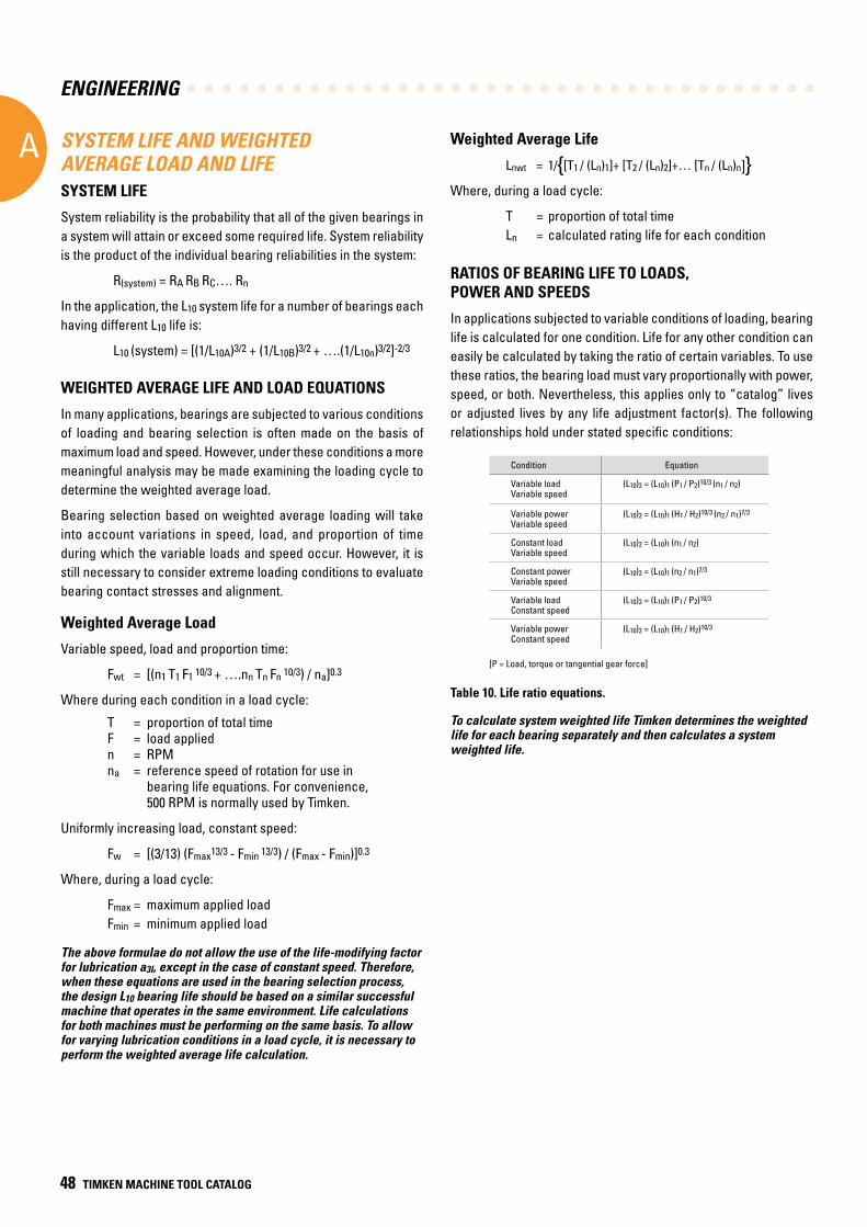
ENGINEERING
A
48 TIMKEN MACHINE TOOL CATALOG
RATIOS OF BEARING LIFE TO LOADS, POWER AND SPEEDS
In applications subjected to variable conditions of loading, bearing life is calculated for one condition. Life for any other condition can easily be calculated by taking the ratio of certain variables. To use these ratios, the bearing load must vary proportionally with power, speed, or both. Nevertheless, this applies only to “catalog” lives or adjusted lives by any life adjustment factor(s). The following relationships hold under stated specific conditions:
Table 10. Life ratio equations.
To calculate system weighted life Timken determines the weighted life for each bearing separately and then calculates a system weighted life.
Weighted Average Life
Lnwt = 1/{[T1 / (Ln)1]+ [T2 / (Ln)2]+… [Tn / (Ln)n]}Where, during a load cycle:
T = proportion of total time Ln = calculated rating life for each condition
SYSTEM LIFE AND WEIGHTED AVERAGE LOAD AND LIFESYSTEM LIFE
System reliability is the probability that all of the given bearings in a system will attain or exceed some required life. System reliability is the product of the individual bearing reliabilities in the system:
R(system) = RA RB RC…. Rn
In the application, the L10 system life for a number of bearings each having different L10 life is:
L10 (system) = [(1/L10A)3/2 + (1/L10B)3/2 + ….(1/L10n)3/2]-2/3
WEIGHTED AVERAGE LIFE AND LOAD EQUATIONS
In many applications, bearings are subjected to various conditions of loading and bearing selection is often made on the basis of maximum load and speed. However, under these conditions a more meaningful analysis may be made examining the loading cycle to determine the weighted average load.
Bearing selection based on weighted average loading will take into account variations in speed, load, and proportion of time during which the variable loads and speed occur. However, it is still necessary to consider extreme loading conditions to evaluate bearing contact stresses and alignment.
Weighted Average Load
Variable speed, load and proportion time:
Fwt = [(n1 T1 F1 10/3 + ….nn Tn Fn 10/3) / na]0.3
Where during each condition in a load cycle:
T = proportion of total time F = load applied n = RPM na = reference speed of rotation for use in bearing life equations. For convenience, 500 RPM is normally used by Timken.
Uniformly increasing load, constant speed:
Fw = [(3/13) (Fmax13/3 - Fmin 13/3) / (Fmax - Fmin)]0.3
Where, during a load cycle:
Fmax = maximum applied load Fmin = minimum applied load
The above formulae do not allow the use of the life-modifying factor for lubrication a3l, except in the case of constant speed. Therefore, when these equations are used in the bearing selection process, the design L10 bearing life should be based on a similar successful machine that operates in the same environment. Life calculations for both machines must be performing on the same basis. To allow for varying lubrication conditions in a load cycle, it is necessary to perform the weighted average life calculation.
Condition Equation
Variable load Variable speed
(L10)2 = (L10)1 (P1 / P2)10/3 (n1 / n2)
Variable power Variable speed
(L10)2 = (L10)1 (H1 / H2)10/3 (n2 / n1)7/3
Constant load Variable speed
(L10)2 = (L10)1 (n1 / n2)
Constant power Variable speed
(L10)2 = (L10)1 (n2 / n1)7/3
Variable load Constant speed
(L10)2 = (L10)1 (P1 / P2)10/3
Variable power Constant speed
(L10)2 = (L10)1 (H1 / H2)10/3
[P = Load, torque or tangential gear force]
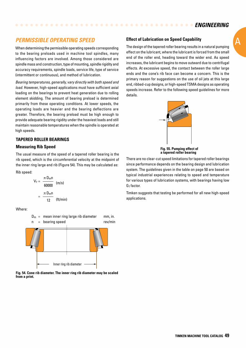
ENGINEERING
A
TIMKEN MACHINE TOOL CATALOG 49
PERMISSIBLE OPERATING SPEEDWhen determining the permissible operating speeds corresponding to the bearing preloads used in machine tool spindles, many influencing factors are involved. Among those considered are spindle mass and construction, type of mounting, spindle rigidity and accuracy requirements, spindle loads, service life, type of service (intermittent or continuous), and method of lubrication.
Bearing temperatures, generally, vary directly with both speed and load. However, high-speed applications must have sufficient axial loading on the bearings to prevent heat generation due to rolling element skidding. The amount of bearing preload is determined primarily from these operating conditions. At lower speeds, the operating loads are heavier and the bearing deflections are greater. Therefore, the bearing preload must be high enough to provide adequate bearing rigidity under the heaviest loads and still maintain reasonable temperatures when the spindle is operated at high speeds.
TAPERED ROLLER BEARINGS
Measuring Rib Speed
The usual measure of the speed of a tapered roller bearing is the rib speed, which is the circumferential velocity at the midpoint of the inner ring large end rib (Figure 54). This may be calculated as:
Rib speed:
Vr = Dmn
60000 (m/s)
= Dmn
12
(ft/min)
Where:
Dm = mean inner ring large rib diameter mm, in. n = bearing speed rev/min
Fig. 54. Cone rib diameter. The inner ring rib diameter may be scaled from a print.
dN value = rib speed (m/s) x 16000
d (m
m)
N(rev/min)
Example: d = 100 mm n = 5000 rev/min
=> 50000 dN
Inner ring rib diameter
Dm = mean inner race large rib diameter mm, in. n = bearing speed rev/min
Effect of Lubrication on Speed Capability
The design of the tapered roller bearing results in a natural pumping effect on the lubricant, where the lubricant is forced from the small end of the roller end, heading toward the wider end. As speed increases, the lubricant begins to move outward due to centrifugal effects. At excessive speed, the contact between the roller large ends and the cone’s rib face can become a concern. This is the primary reason for suggestions on the use of oil jets at this large end, ribbed-cup designs, or high-speed TSMA designs as operating speeds increase. Refer to the following speed guidelines for more details.
There are no clear-cut speed limitations for tapered roller bearings since performance depends on the bearing design and lubrication system. The guidelines given in the table on page 50 are based on typical industrial experiences relating to speed and temperature for various types of lubrication systems, with bearings having low G1 factor.
Timken suggests that testing be performed for all new high-speed applications.
Fig. 55. Pumping effect of a tapered roller bearing
Inner ring rib diameter
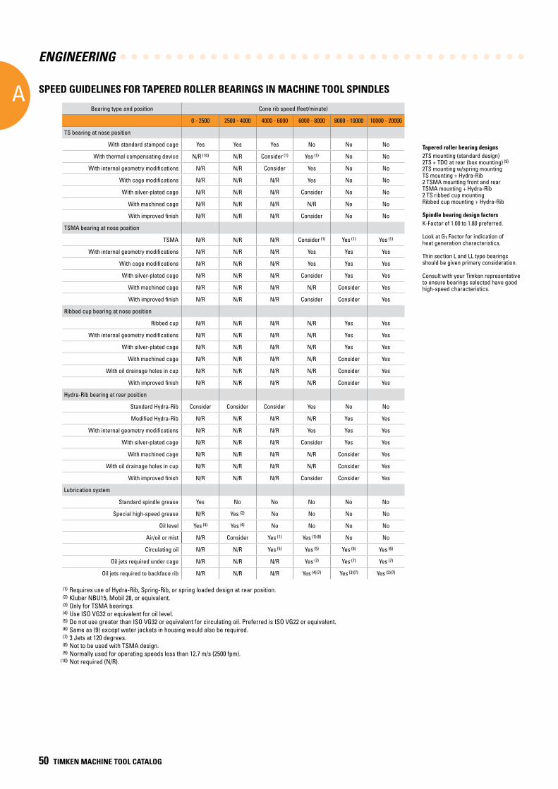
ENGINEERING
A
50 TIMKEN MACHINE TOOL CATALOG
Bearing type and position Cone rib speed (feet/minute)
0 - 2500 2500 - 4000 4000 - 6000 6000 - 8000 8000 - 10000 10000 - 20000
TS bearing at nose position
With standard stamped cage Yes Yes Yes No No No
With thermal compensating device N/R (10) N/R Consider (1) Yes (1) No No
With internal geometry modifications N/R N/R Consider Yes No No
With cage modifications N/R N/R N/R Yes No No
With silver-plated cage N/R N/R N/R Consider No No
With machined cage N/R N/R N/R N/R No No
With improved finish N/R N/R N/R Consider No No
TSMA bearing at nose position
TSMA N/R N/R N/R Consider (1) Yes (1) Yes (1)
With internal geometry modifications N/R N/R N/R Yes Yes Yes
With cage modifications N/R N/R N/R Yes Yes Yes
With silver-plated cage N/R N/R N/R Consider Yes Yes
With machined cage N/R N/R N/R N/R Consider Yes
With improved finish N/R N/R N/R Consider Consider Yes
Ribbed cup bearing at nose position
Ribbed cup N/R N/R N/R N/R Yes Yes
With internal geometry modifications N/R N/R N/R N/R Yes Yes
With silver-plated cage N/R N/R N/R N/R Yes Yes
With machined cage N/R N/R N/R N/R Consider Yes
With oil drainage holes in cup N/R N/R N/R N/R Consider Yes
With improved finish N/R N/R N/R N/R Consider Yes
Hydra-Rib bearing at rear position
Standard Hydra-Rib Consider Consider Consider Yes No No
Modified Hydra-Rib N/R N/R N/R N/R Yes Yes
With internal geometry modifications N/R N/R N/R Yes Yes Yes
With silver-plated cage N/R N/R N/R Consider Yes Yes
With machined cage N/R N/R N/R N/R Consider Yes
With oil drainage holes in cup N/R N/R N/R N/R Consider Yes
With improved finish N/R N/R N/R Consider Consider Yes
Lubrication system
Standard spindle grease Yes No No No No No
Special high-speed grease N/R Yes (2) No No No No
Oil level Yes (4) Yes (4) No No No No
Air/oil or mist N/R Consider Yes (1) Yes (1)(8) No No
Circulating oil N/R N/R Yes (5) Yes (5) Yes (6) Yes (6)
Oil jets required under cage N/R N/R N/R Yes (7) Yes (7) Yes (7)
Oil jets required to backface rib N/R N/R N/R Yes (4)(7) Yes (3)(7) Yes (3)(7)
Tapered roller bearing designs2TS mounting (standard design)2TS + TDO at rear (box mounting) (9)
2TS mounting w/spring mountingTS mounting + Hydra-Rib2 TSMA mounting front and rearTSMA mounting + Hydra-Rib2 TS ribbed cup mountingRibbed cup mounting + Hydra-Rib
Spindle bearing design factorsK-Factor of 1.00 to 1.80 preferred.
Look at G1 Factor for indication ofheat generation characteristics.
Thin section L and LL type bearingsshould be given primary consideration.
Consult with your Timken representative to ensure bearings selected have good high-speed characteristics.
SPEED GUIDELINES FOR TAPERED ROLLER BEARINGS IN MACHINE TOOL SPINDLES
(1) Requires use of Hydra-Rib, Spring-Rib, or spring loaded design at rear position. (2) Kluber NBU15, Mobil 28, or equivalent. (3) Only for TSMA bearings. (4) Use ISO VG32 or equivalent for oil level. (5) Do not use greater than ISO VG32 or equivalent for circulating oil. Preferred is ISO VG22 or equivalent. (6) Same as (9) except water jackets in housing would also be required. (7) 3 Jets at 120 degrees. (8) Not to be used with TSMA design. (9) Normally used for operating speeds less than 12.7 m/s (2500 fpm). (10) Not required (N/R).
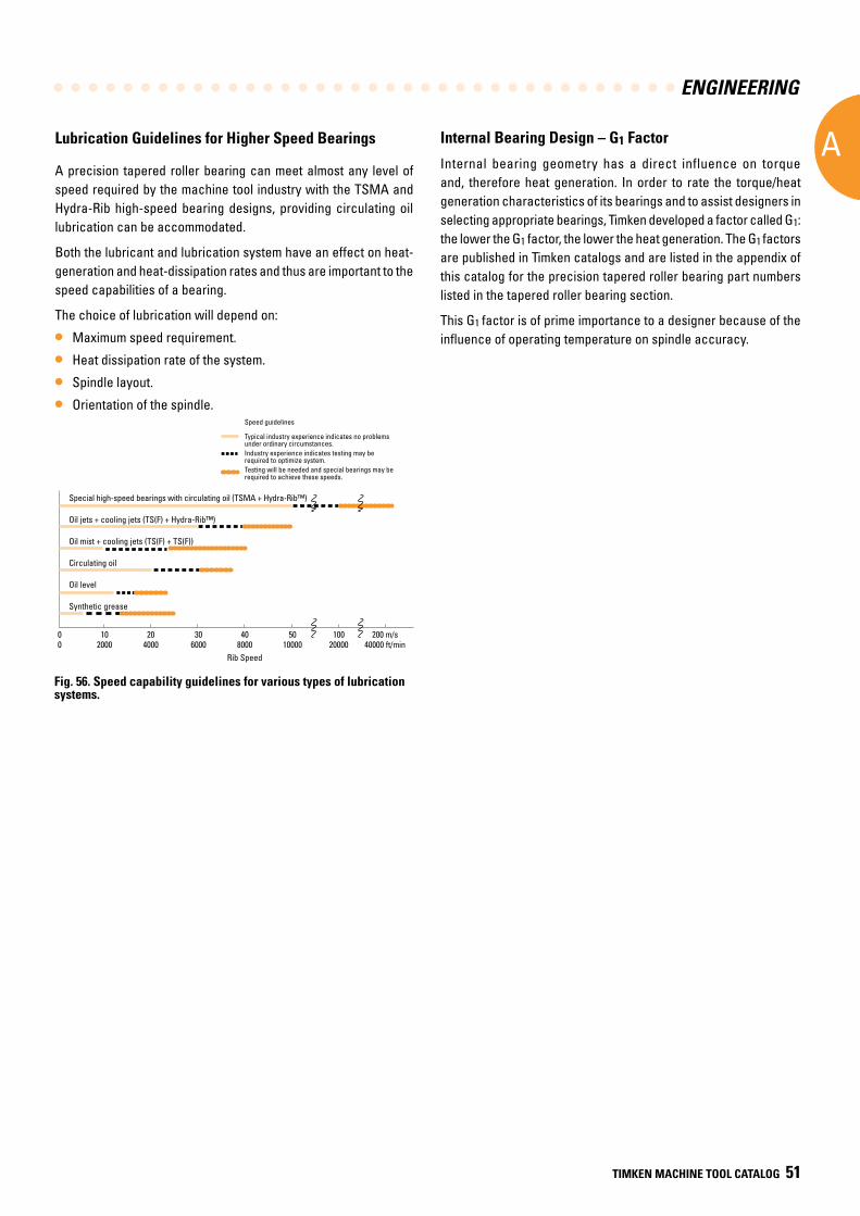
ENGINEERING
A
TIMKEN MACHINE TOOL CATALOG 51
Speed guidelines
Typical industry experience indicates no problems under ordinary circumstances.Industry experience indicates testing may be required to optimize system.Testing will be needed and special bearings may be required to achieve these speeds.
Special high-speed bearings with circulating oil (TSMA + Hydra-Rib™)
Oil jets + cooling jets (TS(F) + Hydra-Rib™)
Oil mist + cooling jets (TS(F) + TS(F))
Circulating oil
Oil level
Synthetic grease
0 10 20 30 40 50 100 200 m/s 0 2000 4000 6000 8000 10000 20000 40000 ft/min Rib Speed
Internal Bearing Design – G1 Factor
Internal bearing geometry has a direct influence on torque and, therefore heat generation. In order to rate the torque/heat generation characteristics of its bearings and to assist designers in selecting appropriate bearings, Timken developed a factor called G1: the lower the G1 factor, the lower the heat generation. The G1 factors are published in Timken catalogs and are listed in the appendix of this catalog for the precision tapered roller bearing part numbers listed in the tapered roller bearing section.
This G1 factor is of prime importance to a designer because of the influence of operating temperature on spindle accuracy.
Fig. 56. Speed capability guidelines for various types of lubrication systems.
Lubrication Guidelines for Higher Speed Bearings
A precision tapered roller bearing can meet almost any level of speed required by the machine tool industry with the TSMA and Hydra-Rib high-speed bearing designs, providing circulating oil lubrication can be accommodated.
Both the lubricant and lubrication system have an effect on heat-generation and heat-dissipation rates and thus are important to the speed capabilities of a bearing.
The choice of lubrication will depend on:
• Maximum speed requirement.
• Heat dissipation rate of the system.
• Spindle layout.
• Orientation of the spindle.
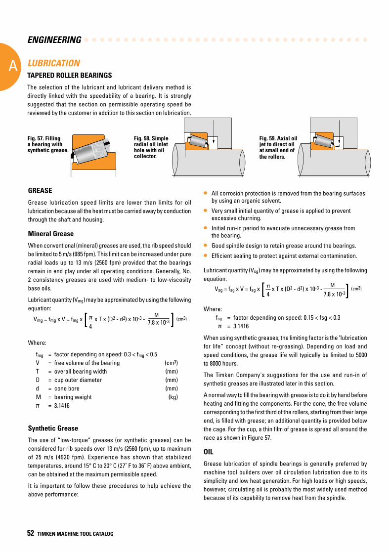
ENGINEERING
A
52 TIMKEN MACHINE TOOL CATALOG
LUBRICATION TAPERED ROLLER BEARINGS
The selection of the lubricant and lubricant delivery method is directly linked with the speedability of a bearing. It is strongly suggested that the section on permissible operating speed be reviewed by the customer in addition to this section on lubrication.
When using synthetic greases, the limiting factor is the "lubrication for life” concept (without re-greasing). Depending on load and speed conditions, the grease life will typically be limited to 5000 to 8000 hours.
The Timken Company's suggestions for the use and run-in of synthetic greases are illustrated later in this section.
A normal way to fill the bearing with grease is to do it by hand before heating and fitting the components. For the cone, the free volume corresponding to the first third of the rollers, starting from their large end, is filled with grease; an additional quantity is provided below the cage. For the cup, a thin film of grease is spread all around the race as shown in Figure 57.
OIL
Grease lubrication of spindle bearings is generally preferred by machine tool builders over oil circulation lubrication due to its simplicity and low heat generation. For high loads or high speeds, however, circulating oil is probably the most widely used method because of its capability to remove heat from the spindle.
GREASE
Grease lubrication speed limits are lower than limits for oil lubrication because all the heat must be carried away by conduction through the shaft and housing.
Mineral Grease
When conventional (mineral) greases are used, the rib speed should be limited to 5 m/s (985 fpm). This limit can be increased under pure radial loads up to 13 m/s (2560 fpm) provided that the bearings remain in end play under all operating conditions. Generally, No. 2 consistency greases are used with medium- to low-viscosity base oils.
Lubricant quantity (Vmg) may be approximated by using the following equation:
Vmg = fmg x V = fmg x [ x T x (D2 - d2) x 10-3 - 7.8 x 10⁻³ ] (cm3)
4
M
Where:
fmg = factor depending on speed: 0.3 < fmg < 0.5V = free volume of the bearing (cm3)T = overall bearing width (mm)D = cup outer diameter (mm)d = cone bore (mm)M = bearing weight (kg)
= 3.1416
Synthetic Grease
The use of “low-torque” greases (or synthetic greases) can be considered for rib speeds over 13 m/s (2560 fpm), up to maximum of 25 m/s (4920 fpm). Experience has shown that stabilized temperatures, around 15° C to 20° C (27˚ F to 36˚ F) above ambient, can be obtained at the maximum permissible speed.
It is important to follow these procedures to help achieve the above performance:
• All corrosion protection is removed from the bearing surfaces by using an organic solvent.
• Very small initial quantity of grease is applied to prevent excessive churning.
• Initial run-in period to evacuate unnecessary grease from the bearing.
• Good spindle design to retain grease around the bearings.
• Efficient sealing to protect against external contamination.
Lubricant quantity (Vsg) may be approximated by using the following equation:
Vsg = fsg x V = fsg x [ x T x (D2 - d2) x 10-3 - 7.8 x 10⁻³] (cm3)
4 M
Where: fsg = factor depending on speed: 0.15 < fsg < 0.3 = 3.1416
Fig. 58. Simple radial oil inlet hole with oil collector.
Fig. 59. Axial oil jet to direct oil at small end of the rollers.
Fig. 57. Filling a bearing with synthetic grease.
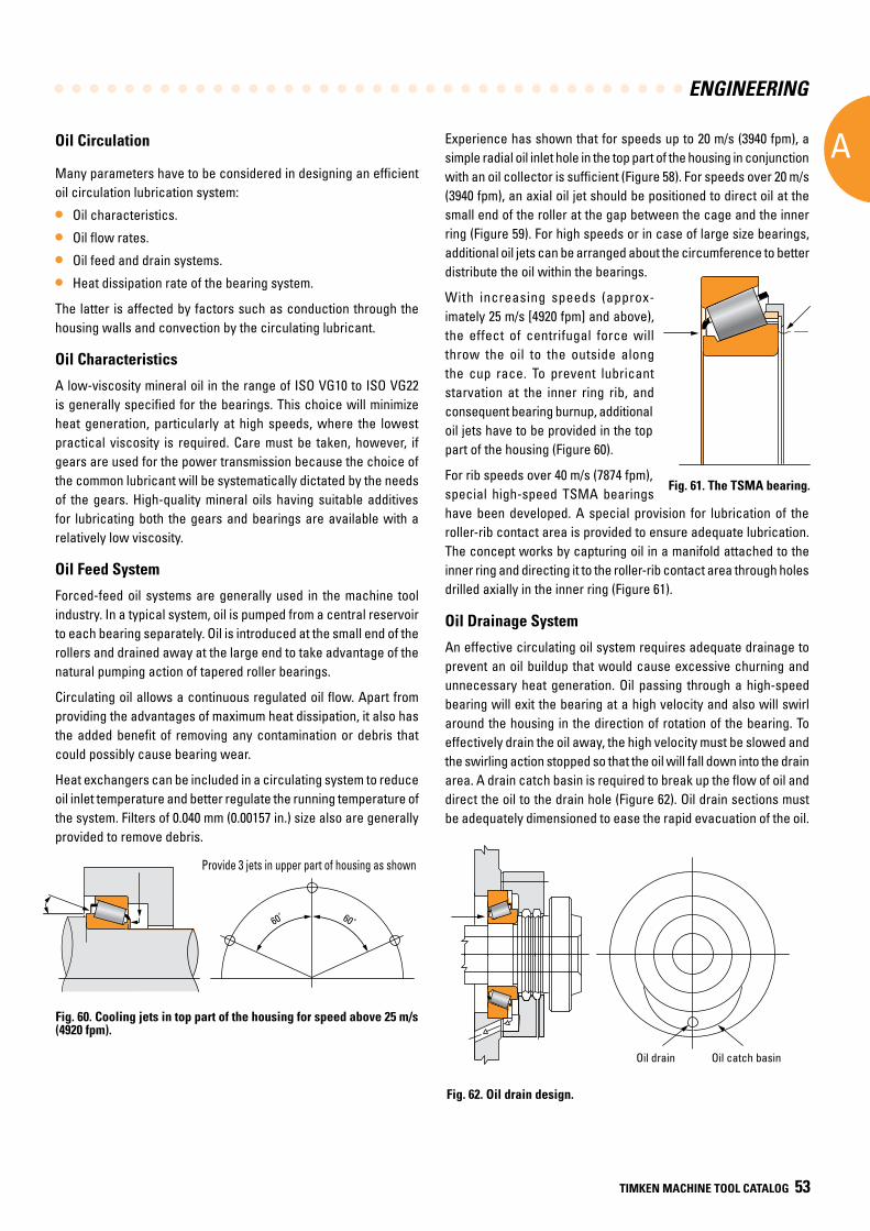
ENGINEERING
A
TIMKEN MACHINE TOOL CATALOG 53
• All corrosion protection is removed from the bearing surfaces by using an organic solvent.
• Very small initial quantity of grease is applied to prevent excessive churning.
• Initial run-in period to evacuate unnecessary grease from the bearing.
• Good spindle design to retain grease around the bearings.
• Efficient sealing to protect against external contamination.
Lubricant quantity (Vsg) may be approximated by using the following equation:
Vsg = fsg x V = fsg x [ x T x (D2 - d2) x 10-3 - 7.8 x 10⁻³] (cm3)
4 M
Where: fsg = factor depending on speed: 0.15 < fsg < 0.3 = 3.1416
Oil drain Oil catch basin
Oil Circulation
Many parameters have to be considered in designing an efficient oil circulation lubrication system:
• Oil characteristics.
• Oil flow rates.
• Oil feed and drain systems.
• Heat dissipation rate of the bearing system.
The latter is affected by factors such as conduction through the housing walls and convection by the circulating lubricant.
Oil Characteristics
A low-viscosity mineral oil in the range of ISO VG10 to ISO VG22 is generally specified for the bearings. This choice will minimize heat generation, particularly at high speeds, where the lowest practical viscosity is required. Care must be taken, however, if gears are used for the power transmission because the choice of the common lubricant will be systematically dictated by the needs of the gears. High-quality mineral oils having suitable additives for lubricating both the gears and bearings are available with a relatively low viscosity.
Oil Feed System
Forced-feed oil systems are generally used in the machine tool industry. In a typical system, oil is pumped from a central reservoir to each bearing separately. Oil is introduced at the small end of the rollers and drained away at the large end to take advantage of the natural pumping action of tapered roller bearings.
Circulating oil allows a continuous regulated oil flow. Apart from providing the advantages of maximum heat dissipation, it also has the added benefit of removing any contamination or debris that could possibly cause bearing wear.
Heat exchangers can be included in a circulating system to reduce oil inlet temperature and better regulate the running temperature of the system. Filters of 0.040 mm (0.00157 in.) size also are generally provided to remove debris.
Experience has shown that for speeds up to 20 m/s (3940 fpm), a simple radial oil inlet hole in the top part of the housing in conjunction with an oil collector is sufficient (Figure 58). For speeds over 20 m/s (3940 fpm), an axial oil jet should be positioned to direct oil at the small end of the roller at the gap between the cage and the inner ring (Figure 59). For high speeds or in case of large size bearings, additional oil jets can be arranged about the circumference to better distribute the oil within the bearings.
With increasing speeds (approx-imately 25 m/s [4920 fpm] and above), the effect of centrifugal force will throw the oil to the outside along the cup race. To prevent lubricant starvation at the inner ring rib, and consequent bearing burnup, additional oil jets have to be provided in the top part of the housing (Figure 60).
For rib speeds over 40 m/s (7874 fpm), special high-speed TSMA bearings have been developed. A special provision for lubrication of the roller-rib contact area is provided to ensure adequate lubrication. The concept works by capturing oil in a manifold attached to the inner ring and directing it to the roller-rib contact area through holes drilled axially in the inner ring (Figure 61).
Oil Drainage System
An effective circulating oil system requires adequate drainage to prevent an oil buildup that would cause excessive churning and unnecessary heat generation. Oil passing through a high-speed bearing will exit the bearing at a high velocity and also will swirl around the housing in the direction of rotation of the bearing. To effectively drain the oil away, the high velocity must be slowed and the swirling action stopped so that the oil will fall down into the drain area. A drain catch basin is required to break up the flow of oil and direct the oil to the drain hole (Figure 62). Oil drain sections must be adequately dimensioned to ease the rapid evacuation of the oil.
Fig. 62. Oil drain design.
Fig. 60. Cooling jets in top part of the housing for speed above 25 m/s (4920 fpm).
Oil drain Oil catch basin
Provide 3 jets in upper part of housing as shown
60˚ 60˚
Fig. 61. The TSMA bearing.
Provide 3 jets in upper part of housing as shown
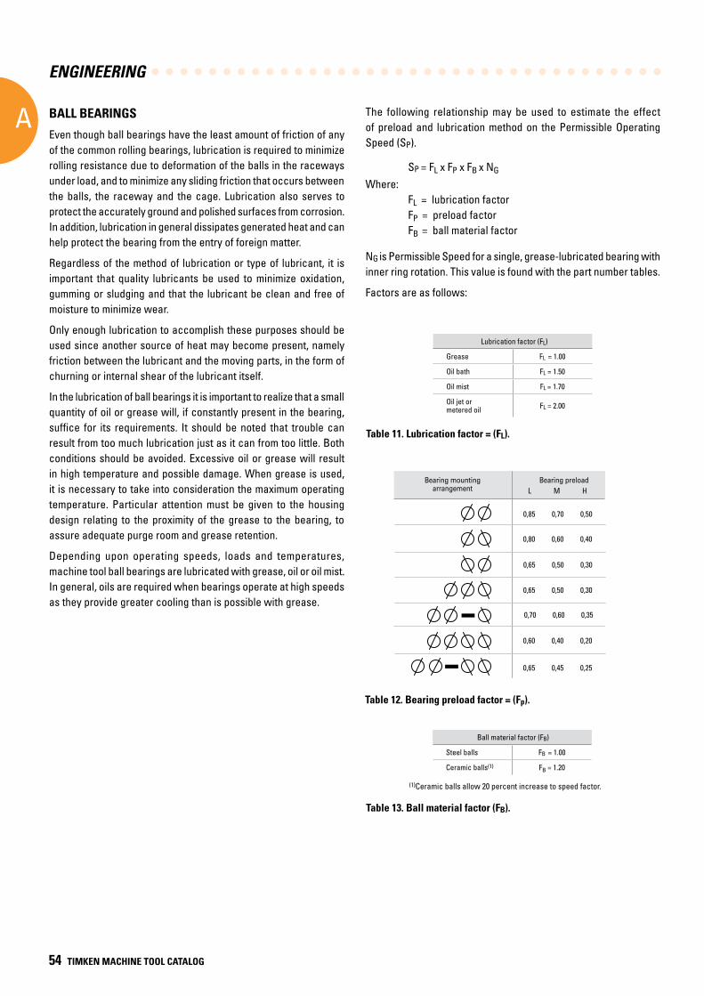
ENGINEERING
A
54 TIMKEN MACHINE TOOL CATALOG
BALL BEARINGS
Even though ball bearings have the least amount of friction of any of the common rolling bearings, lubrication is required to minimize rolling resistance due to deformation of the balls in the raceways under load, and to minimize any sliding friction that occurs between the balls, the raceway and the cage. Lubrication also serves to protect the accurately ground and polished surfaces from corrosion. In addition, lubrication in general dissipates generated heat and can help protect the bearing from the entry of foreign matter.
Regardless of the method of lubrication or type of lubricant, it is important that quality lubricants be used to minimize oxidation, gumming or sludging and that the lubricant be clean and free of moisture to minimize wear.
Only enough lubrication to accomplish these purposes should be used since another source of heat may become present, namely friction between the lubricant and the moving parts, in the form of churning or internal shear of the lubricant itself.
In the lubrication of ball bearings it is important to realize that a small quantity of oil or grease will, if constantly present in the bearing, suffice for its requirements. It should be noted that trouble can result from too much lubrication just as it can from too little. Both conditions should be avoided. Excessive oil or grease will result in high temperature and possible damage. When grease is used, it is necessary to take into consideration the maximum operating temperature. Particular attention must be given to the housing design relating to the proximity of the grease to the bearing, to assure adequate purge room and grease retention.
Depending upon operating speeds, loads and temperatures, machine tool ball bearings are lubricated with grease, oil or oil mist. In general, oils are required when bearings operate at high speeds as they provide greater cooling than is possible with grease.
The following relationship may be used to estimate the effect of preload and lubrication method on the Permissible Operating Speed (SP).
SP = FL x FP x FB x NG
Where: FL = lubrication factor FP = preload factor FB = ball material factor
NG is Permissible Speed for a single, grease-lubricated bearing with inner ring rotation. This value is found with the part number tables.
Factors are as follows:
Lubrication factor (FL)
Grease FL = 1.00
Oil bath FL = 1.50
Oil mist FL = 1.70
Oil jet or metered oil FL = 2.00
Table 13. Ball material factor (FB).
(1)Ceramic balls allow 20 percent increase to speed factor.
Ball material factor (FB)
Steel balls FB = 1.00
Ceramic balls(1) FB = 1.20
Table 12. Bearing preload factor = (Fp).
Table 11. Lubrication factor = (FL).
L M H
0,85 0,70 0,50
0,80 0,60 0,40
0,65 0,50 0,30
0,65 0,50 0,30
0,70 0,60 0,35
0,60 0,40 0,20
0,65 0,45 0,25
Bearing mounting arrangement
Bearing preload
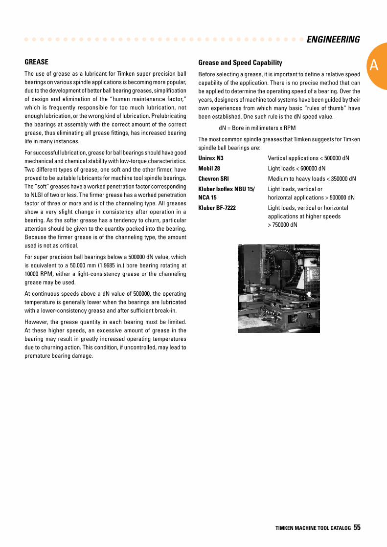
ENGINEERING
A
TIMKEN MACHINE TOOL CATALOG 55
GREASE
The use of grease as a lubricant for Timken super precision ball bearings on various spindle applications is becoming more popular, due to the development of better ball bearing greases, simplification of design and elimination of the “human maintenance factor,” which is frequently responsible for too much lubrication, not enough lubrication, or the wrong kind of lubrication. Prelubricating the bearings at assembly with the correct amount of the correct grease, thus eliminating all grease fittings, has increased bearing life in many instances.
For successful lubrication, grease for ball bearings should have good mechanical and chemical stability with low-torque characteristics. Two different types of grease, one soft and the other firmer, have proved to be suitable lubricants for machine tool spindle bearings. The “soft” greases have a worked penetration factor corresponding to NLGI of two or less. The firmer grease has a worked penetration factor of three or more and is of the channeling type. All greases show a very slight change in consistency after operation in a bearing. As the softer grease has a tendency to churn, particular attention should be given to the quantity packed into the bearing. Because the firmer grease is of the channeling type, the amount used is not as critical.
For super precision ball bearings below a 500000 dN value, which is equivalent to a 50.000 mm (1.9685 in.) bore bearing rotating at 10000 RPM, either a light-consistency grease or the channeling grease may be used.
At continuous speeds above a dN value of 500000, the operating temperature is generally lower when the bearings are lubricated with a lower-consistency grease and after sufficient break-in.
However, the grease quantity in each bearing must be limited. At these higher speeds, an excessive amount of grease in the bearing may result in greatly increased operating temperatures due to churning action. This condition, if uncontrolled, may lead to premature bearing damage.
Grease and Speed Capability
Before selecting a grease, it is important to define a relative speed capability of the application. There is no precise method that can be applied to determine the operating speed of a bearing. Over the years, designers of machine tool systems have been guided by their own experiences from which many basic “rules of thumb” have been established. One such rule is the dN speed value.
dN = Bore in millimeters x RPM
The most common spindle greases that Timken suggests for Timken spindle ball bearings are:
Unirex N3 Vertical applications < 500000 dN
Mobil 28 Light loads < 600000 dN
Chevron SRI Medium to heavy loads < 350000 dN
Kluber Isoflex NBU 15/ Light loads, vertical or NCA 15 horizontal applications > 500000 dN
Kluber BF-7222 Light loads, vertical or horizontal applications at higher speeds > 750000 dN
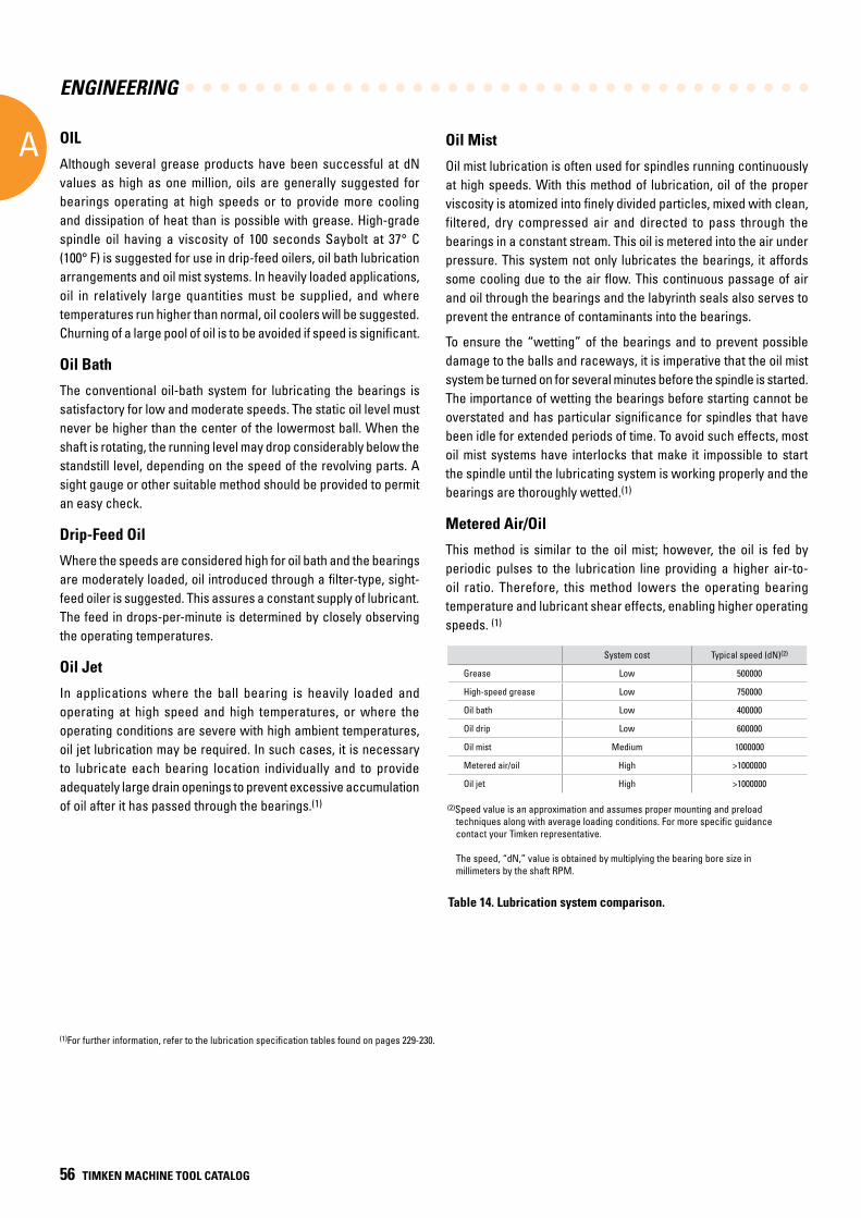
ENGINEERING
A
56 TIMKEN MACHINE TOOL CATALOG
OIL
Although several grease products have been successful at dN values as high as one million, oils are generally suggested for bearings operating at high speeds or to provide more cooling and dissipation of heat than is possible with grease. High-grade spindle oil having a viscosity of 100 seconds Saybolt at 37° C (100° F) is suggested for use in drip-feed oilers, oil bath lubrication arrangements and oil mist systems. In heavily loaded applications, oil in relatively large quantities must be supplied, and where temperatures run higher than normal, oil coolers will be suggested. Churning of a large pool of oil is to be avoided if speed is significant.
Oil Bath
The conventional oil-bath system for lubricating the bearings is satisfactory for low and moderate speeds. The static oil level must never be higher than the center of the lowermost ball. When the shaft is rotating, the running level may drop considerably below the standstill level, depending on the speed of the revolving parts. A sight gauge or other suitable method should be provided to permit an easy check.
Drip-Feed Oil
Where the speeds are considered high for oil bath and the bearings are moderately loaded, oil introduced through a filter-type, sight-feed oiler is suggested. This assures a constant supply of lubricant. The feed in drops-per-minute is determined by closely observing the operating temperatures.
Oil Jet
In applications where the ball bearing is heavily loaded and operating at high speed and high temperatures, or where the operating conditions are severe with high ambient temperatures, oil jet lubrication may be required. In such cases, it is necessary to lubricate each bearing location individually and to provide adequately large drain openings to prevent excessive accumulation of oil after it has passed through the bearings.(1)
Oil Mist
Oil mist lubrication is often used for spindles running continuously at high speeds. With this method of lubrication, oil of the proper viscosity is atomized into finely divided particles, mixed with clean, filtered, dry compressed air and directed to pass through the bearings in a constant stream. This oil is metered into the air under pressure. This system not only lubricates the bearings, it affords some cooling due to the air flow. This continuous passage of air and oil through the bearings and the labyrinth seals also serves to prevent the entrance of contaminants into the bearings.
To ensure the “wetting” of the bearings and to prevent possible damage to the balls and raceways, it is imperative that the oil mist system be turned on for several minutes before the spindle is started. The importance of wetting the bearings before starting cannot be overstated and has particular significance for spindles that have been idle for extended periods of time. To avoid such effects, most oil mist systems have interlocks that make it impossible to start the spindle until the lubricating system is working properly and the bearings are thoroughly wetted.(1)
Metered Air/Oil
This method is similar to the oil mist; however, the oil is fed by periodic pulses to the lubrication line providing a higher air-to-oil ratio. Therefore, this method lowers the operating bearing temperature and lubricant shear effects, enabling higher operating speeds. (1)
System cost Typical speed (dN)(2)
Grease Low 500000
High-speed grease Low 750000
Oil bath Low 400000
Oil drip Low 600000
Oil mist Medium 1000000
Metered air/oil High >1000000
Oil jet High >1000000
(2)Speed value is an approximation and assumes proper mounting and preload techniques along with average loading conditions. For more specific guidance contact your Timken representative.
The speed, “dN,” value is obtained by multiplying the bearing bore size in millimeters by the shaft RPM.
Table 14. Lubrication system comparison.
(1)For further information, refer to the lubrication specification tables found on pages 229-230.
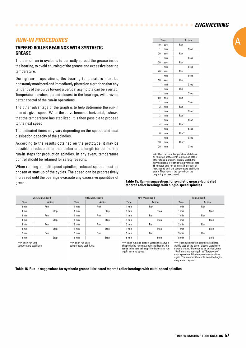
ENGINEERING
A
TIMKEN MACHINE TOOL CATALOG 57
25% Max. speed 50% Max. speed 75% Max speed Max. speed
Time Action Time Action Time Action Time Action
1 min Run 1 min Run 1 min Run 1 min Run
1 min Stop 1 min Stop 1 min Stop 1 min Stop
1 min Run 1 min Run 1 min Run 1 min Run
1 min Stop 1 min Stop 1 min Stop 1 min Stop
2 min Run 2 min Run 2 min Run 2 min Run
1 min Stop 1 min Stop 1 min Stop 1 min Stop
3 min Run 3 min Run 3 min Run 3 min Run
5 min Stop 5 min Stop 5 min Stop 5 min Stop
⇒ Then run until temperature stabilizes.
⇒ Then run until temperature stabilizes.
⇒ Then run and closely watch the curve’s shape during running, until stabilization. If it tends to be vertical, stop 15 minutes and run again at same speed.
⇒ Then run until temperature stabilizes. At this step of the cycle, closely watch the curve’s shape. If it tends to be vertical, stop 15 minutes and run again at 75 percent of max. speed until the temperature stabilizes again. Then restart the cycle from the begin-ning at max. speed.
Time Action
10 sec Run
1 min Stop
20 sec Run
1 min Stop
30 sec Run
1 min Stop
40 sec Run
1 min Stop
50 sec Run
1 min Stop
1 min Run
1 min Stop
90 sec Run
1 min Stop
2 min Run
1 min Stop
3 min Run*
1 min Stop
4 min Run*
1 min Stop
6 min Run*
1 min Stop
10 min Run*
20 min Stop
RUN-IN PROCEDURESTAPERED ROLLER BEARINGS WITH SYNTHETIC GREASE
The aim of run-in cycles is to correctly spread the grease inside the bearing, to avoid churning of the grease and excessive bearing temperature.
During run-in operations, the bearing temperature must be constantly monitored and immediately plotted on a graph so that any tendency of the curve toward a vertical asymptote can be averted. Temperature probes, placed closest to the bearings, will provide better control of the run-in operations.
The other advantage of the graph is to help determine the run-in time at a given speed. When the curve becomes horizontal, it shows that the temperature has stabilized. It is then possible to proceed to the next speed.
The indicated times may vary depending on the speeds and heat dissipation capacity of the spindles.
According to the results obtained on the prototype, it may be possible to reduce either the number or the length (or both) of the run-in steps for production spindles. In any event, temperature control should be retained for safety reasons.
When running-in multi-speed spindles, reduced speeds must be chosen at start-up of the cycles. The speed can be progressively increased until the bearings evacuate any excessive quantities of grease.
Table 16. Run-in suggestions for synthetic grease-lubricated tapered roller bearings with multi-speed spindles.
⇒ Then run until temperature stabilizes. At this step of the cycle, as well as at the other steps marked *, closely watch the curve’s shape. If it tends to be vertical, stop 15 minutes and run again at 75 percent of max. speed until the temperature stabilizes again. Then restart the cycle from the beginning at max. speed.
Table 15. Run-in suggestions for synthetic grease-lubricated tapered roller bearings with single-speed spindles.
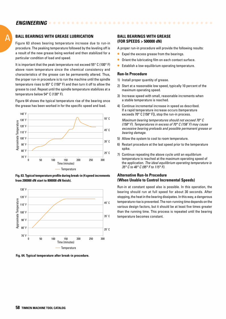
ENGINEERING
A
58 TIMKEN MACHINE TOOL CATALOG
BALL BEARINGS WITH GREASE (FOR SPEEDS > 500000 dN)
A proper run-in procedure will provide the following results:
• Expel the excess grease from the bearings.
• Orient the lubricating film on each contact surface.
• Establish a low-equilibrium operating temperature.
Run-In Procedure1) Install proper quantity of grease.
2) Start at a reasonable low speed, typically 10 percent of the maximum operating speed.
3) Increase speed with small, reasonable increments when a stable temperature is reached.
4) Continue incremental increase in speed as described. If a rapid temperature increase occurs (temperature exceeds 70° C [158° F]), stop the run-in process.
Maximum bearing temperatures should not exceed 70° C (158° F). Temperatures in excess of 70° C (158˚ F) may cause excessive bearing preloads and possible permanent grease or bearing damage.
5) Allow the system to cool to room temperature.
6) Restart procedure at the last speed prior to the temperature spike.
7) Continue repeating the above cycle until an equilibrium temperature is reached at the maximum operating speed of the application. The ideal equilibrium operating temperature is 35° C to 46° C (95° F to 115° F).
Alternative Run-In Procedure (When Unable to Control Incremental Speeds)
Run-in at constant speed also is possible. In this operation, the bearing should run at full speed for about 30 seconds. After stopping, the heat in the bearing dissipates. In this way, a dangerous temperature rise is prevented. The non-running time depends on the various design factors, but it should be at least five times greater than the running time. This process is repeated until the bearing temperature becomes constant.
BALL BEARINGS WITH GREASE LUBRICATION
Figure 63 shows bearing temperature increase due to run-in procedure. The peaking temperature followed by the leveling off is a result of the new grease being worked and then stabilized for a particular condition of load and speed.
It is important that the peak temperature not exceed 55° C (100° F) above room temperature since the chemical consistency and characteristics of the grease can be permanently altered. Thus, the proper run-in procedure is to run the machine until the spindle temperature rises to 65° C (150° F) and then turn it off to allow the grease to cool. Repeat until the spindle temperature stabilizes at a temperature below 54° C (130° F).
Figure 64 shows the typical temperature rise of the bearing once the grease has been worked in for the specific speed and load.
Fig. 63. Typical temperature profile during break-in (4 speed increments from 200000 dN start to 800000 dN finish).
Fig. 64. Typical temperature after break-in procedure.
Appr
oxim
ate
Tem
pera
ture
Time (minutes)0
70˚ F
80˚ F
90˚ F
100˚ F
110˚ F
120˚ F
130˚ F
140˚ F
50 100 150 200 250 300
Temperature
Appr
oxim
ate
Tem
pera
ture
Time (minutes)0
70˚ F
80˚ F
90˚ F
100˚ F
110˚ F
120˚ F
130˚ F
25˚ C
35˚ C
45˚ C
25˚ C
35˚ C
45˚ C
55˚ C
50 100 150 200 250 300
Temperature
Time (minutes)
Time (minutes)
Appr
oxim
ate T
empe
ratu
re
Appr
oxim
ate T
empe
ratu
re
Temperature
Temperature
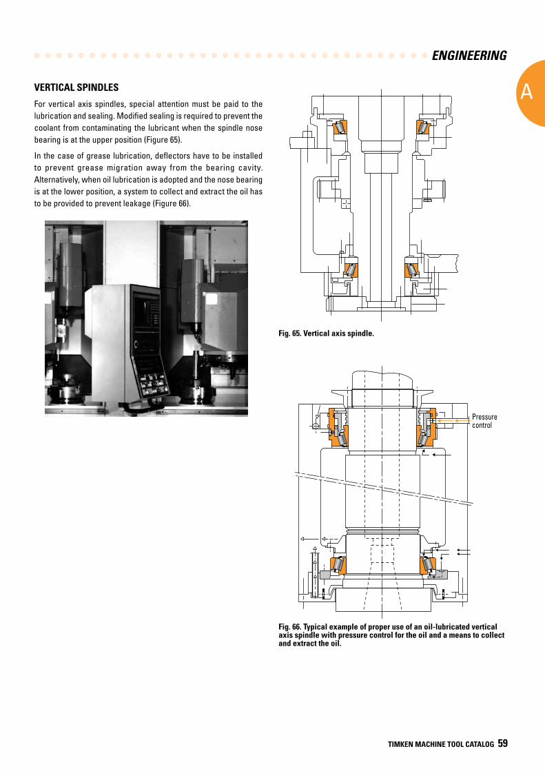
ENGINEERING
A
TIMKEN MACHINE TOOL CATALOG 59
VERTICAL SPINDLES
For vertical axis spindles, special attention must be paid to the lubrication and sealing. Modified sealing is required to prevent the coolant from contaminating the lubricant when the spindle nose bearing is at the upper position (Figure 65).
In the case of grease lubrication, deflectors have to be installed to prevent grease migration away from the bearing cavity. Alternatively, when oil lubrication is adopted and the nose bearing is at the lower position, a system to collect and extract the oil has to be provided to prevent leakage (Figure 66).
Fig. 65. Vertical axis spindle.
Pressurecontrol
Fig. 66. Typical example of proper use of an oil-lubricated vertical axis spindle with pressure control for the oil and a means to collect and extract the oil.
Pressure control
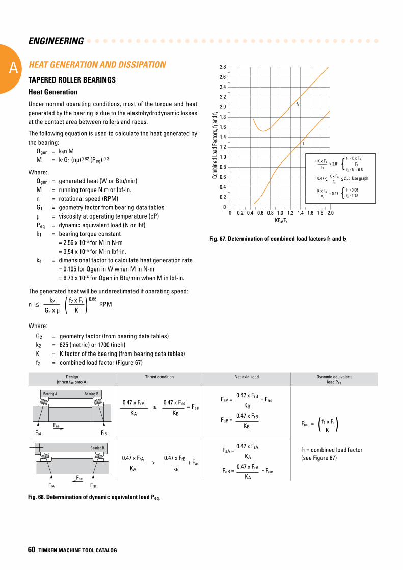
ENGINEERING
A
60 TIMKEN MACHINE TOOL CATALOG
The generated heat will be underestimated if operating speed:
n k2 (
f2 x Fr ) 0.66 RPM
G2 x µ K
Where:
G2 = geometry factor (from bearing data tables) k2 = 625 (metric) or 1700 (inch) K = K factor of the bearing (from bearing data tables) f2 = combined load factor (Figure 67)
HEAT GENERATION AND DISSIPATION
TAPERED ROLLER BEARINGS
Heat Generation
Under normal operating conditions, most of the torque and heat generated by the bearing is due to the elastohydrodynamic losses at the contact area between rollers and races.
The following equation is used to calculate the heat generated by the bearing: Qgen = k4n M M = k1G1 (nμ)0.62 (Peq) 0.3
Where:Qgen = generated heat (W or Btu/min)M = running torque N.m or lbf-in.n = rotational speed (RPM)G1 = geometry factor from bearing data tablesμ = viscosity at operating temperature (cP)Peq = dynamic equivalent load (N or lbf)k1 = bearing torque constant = 2.56 x 10⁻⁶ for M in N-m = 3.54 x 10⁻⁵ for M in lbf-in.k4 = dimensional factor to calculate heat generation rate = 0.105 for Qgen in W when M in N-m = 6.73 x 10⁻⁴ for Qgen in Btu/min when M in lbf-in.
Fig. 67. Determination of combined load factors f1 and f2.
0.2
Com
bine
d Lo
ad F
acto
rs. f
1 and
f 2
f1
f2
0
0.4
0.6
0.8
1.2
1.0
1.4
1.6
1.8
2.0
2.2
2.4
2.6
2.8
0 0.2 0.4 0.6 0.8 1.21.0 1.4 1.6 1.8 2.0KFa/Fr
if K x Fa
Fr> 2.0
f1 = K x Fa
Fr
f2 = f1 + 0.8{
if K x Fa
Fr= 0.47
f1 = 0.06f2 = 1.78{
K x Fa
Frif 0.47 < < 2.0: Use graph- -Co
mbine
d Loa
d Fac
tors
, f 1 an
d f2
Use graph
if
if
if
Design(thrust fae onto A)
Thrust condition Net axial load Dynamic equivalentload Peq
FaA = 0.47 x FrB + Fae
KB
FaB = 0.47 x FrB
KB
Peq = (f1 x Fr) K
f1 = combined load factor(see Figure 67)
0.47 x FrA ≤
0.47 x FrB + Fae KA KB
FaA = 0.47 x FrA
KA
FaB = 0.47 x FrA - Fae
KA
0.47 x FrA > 0.47 x FrB + Fae
KA KB
Fig. 68. Determination of dynamic equivalent load Peq.
FrA FrB
Fae
FrA FrB
Fae
Bearing A Bearing B
Bearing B
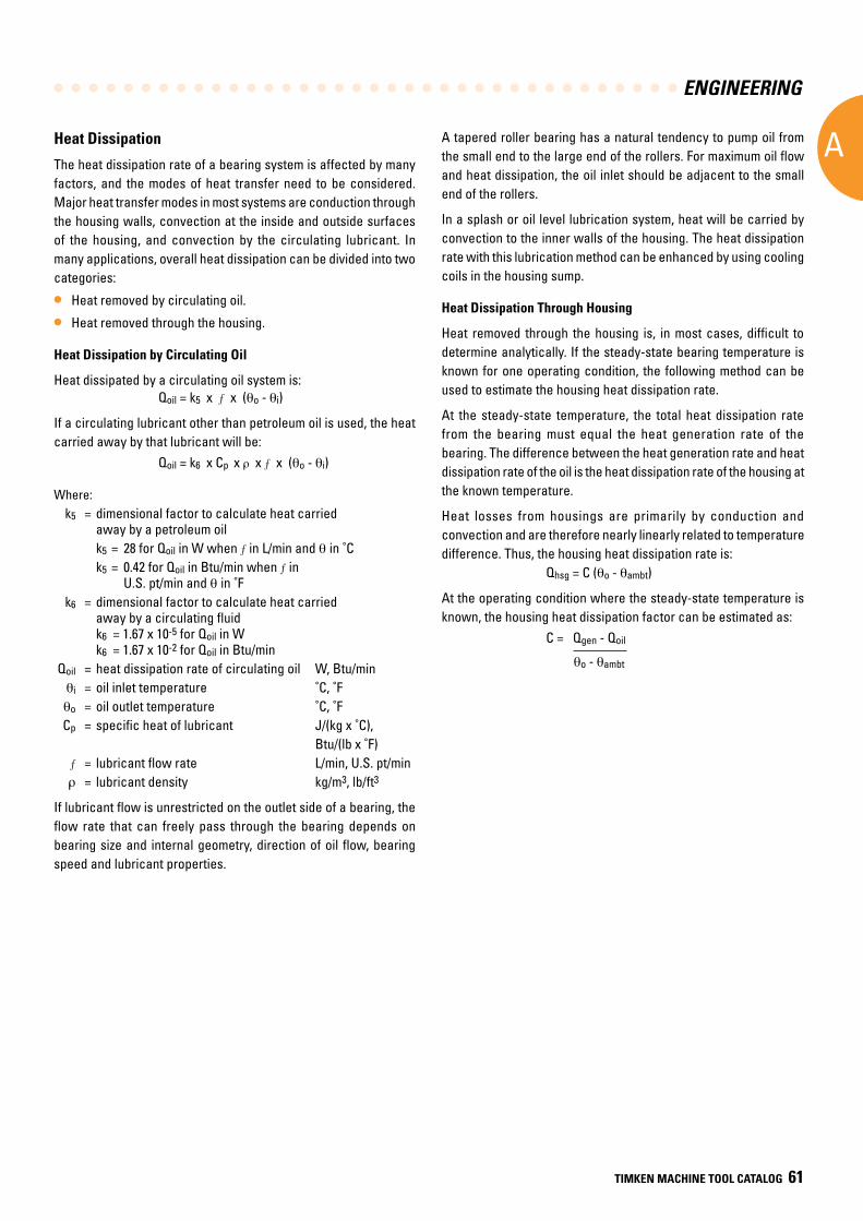
ENGINEERING
A
TIMKEN MACHINE TOOL CATALOG 61
Heat Dissipation
The heat dissipation rate of a bearing system is affected by many factors, and the modes of heat transfer need to be considered. Major heat transfer modes in most systems are conduction through the housing walls, convection at the inside and outside surfaces of the housing, and convection by the circulating lubricant. In many applications, overall heat dissipation can be divided into two categories:
• Heat removed by circulating oil.
• Heat removed through the housing.
Heat Dissipation by Circulating Oil
Heat dissipated by a circulating oil system is: Qoil = k5 x x (qo - qi)
If a circulating lubricant other than petroleum oil is used, the heat carried away by that lubricant will be: Qoil = k6 x Cp x r x x (qo - qi)
Where: k5 = dimensional factor to calculate heat carried
away by a petroleum oil k5 = 28 for Qoil in W when in L/min and q in ˚C k5 = 0.42 for Qoil in Btu/min when in
U.S. pt/min and q in ˚F k6 = dimensional factor to calculate heat carried
away by a circulating fluid k6 = 1.67 x 10⁻⁵ for Qoil in W k6 = 1.67 x 10⁻² for Qoil in Btu/min Qoil = heat dissipation rate of circulating oil W, Btu/min qi = oil inlet temperature ˚C, ˚F qo = oil outlet temperature ˚C, ˚F Cp = specific heat of lubricant J/(kg x ˚C),
Btu/(lb x ˚F) = lubricant flow rate L/min, U.S. pt/min r = lubricant density kg/m3, lb/ft3
If lubricant flow is unrestricted on the outlet side of a bearing, the flow rate that can freely pass through the bearing depends on bearing size and internal geometry, direction of oil flow, bearing speed and lubricant properties.
A tapered roller bearing has a natural tendency to pump oil from the small end to the large end of the rollers. For maximum oil flow and heat dissipation, the oil inlet should be adjacent to the small end of the rollers.
In a splash or oil level lubrication system, heat will be carried by convection to the inner walls of the housing. The heat dissipation rate with this lubrication method can be enhanced by using cooling coils in the housing sump.
Heat Dissipation Through Housing
Heat removed through the housing is, in most cases, difficult to determine analytically. If the steady-state bearing temperature is known for one operating condition, the following method can be used to estimate the housing heat dissipation rate.
At the steady-state temperature, the total heat dissipation rate from the bearing must equal the heat generation rate of the bearing. The difference between the heat generation rate and heat dissipation rate of the oil is the heat dissipation rate of the housing at the known temperature.
Heat losses from housings are primarily by conduction and convection and are therefore nearly linearly related to temperature difference. Thus, the housing heat dissipation rate is: Qhsg = C (qo - qambt)
At the operating condition where the steady-state temperature is known, the housing heat dissipation factor can be estimated as:
C = Qgen - Qoil
qo - qambt
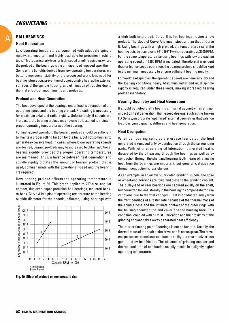
ENGINEERING
A
62 TIMKEN MACHINE TOOL CATALOG
BALL BEARINGS
Heat Generation
Low operating temperatures, combined with adequate spindle rigidity, are important and highly desirable for precision machine tools. This is particularly true for high-speed grinding spindles where the preload of the bearings is the principal load imposed upon them. Some of the benefits derived from low operating temperatures are better dimensional stability of the processed work, less need for bearing lubrication, prevention of objectionable heat at the external surfaces of the spindle housing, and elimination of troubles due to thermal effects on mounting fits and preloads.
Preload and Heat Generation
The heat developed at the bearings under load is a function of the operating speed and the bearing preload. Preloading is necessary for maximum axial and radial rigidity. Unfortunately, if speeds are increased, the bearing preload may have to be lessened to maintain proper operating temperatures at the bearing.
For high-speed operation, the bearing preload should be sufficient to maintain proper rolling friction for the balls, but not so high as to generate excessive heat. In cases where lower operating speeds are desired, bearing preloads may be increased to obtain additional bearing rigidity, provided the proper operating temperatures are maintained. Thus, a balance between heat generation and spindle rigidity dictates the amount of bearing preload that is used, commensurate with the operational speed and the bearing life required.
How bearing preload affects the operating temperature is illustrated in Figure 69. This graph applies to 207-size, angular contact, duplexed super precision ball bearings, mounted back-to-back. Curve A is a plot of operating temperature at the bearing outside diameter for the speeds indicated, using bearings with
a high built-in preload. Curve B is for bearings having a low preload. The slope of Curve A is much steeper than that of Curve B. Using bearings with a high preload, the temperature rise at the bearing outside diameter is 34˚ C (93° F) when operating at 3600 RPM. For the same temperature rise using bearings with low preload, an operating speed of 15300 RPM is indicated. Therefore, it is evident that for higher-speed operation, the bearing preload should be kept to the minimum necessary to ensure sufficient bearing rigidity.
For workhead spindles, the operating speeds are generally low and the loading conditions heavy. Maximum radial and axial spindle rigidity is required under these loads, making increased bearing preload mandatory.
Bearing Geometry and Heat Generation
It should be noted that a bearing's internal geometry has a major impact on heat generation. High-speed designs, such as the Timken HX Series, incorporate “optimized” internal geometries that balance load-carrying capacity, stiffness and heat generation.
Heat Dissipation
When ball bearing spindles are grease lubricated, the heat generated is removed only by conduction through the surrounding parts. With jet or circulating oil lubrication, generated heat is dissipated by the oil passing through the bearings as well as by conduction through the shaft and housing. Both means of removing heat from the bearings are important, but generally, dissipation through conduction is less obvious.
As an example, in an oil mist-lubricated grinding spindle, the nose or wheel-end bearings are fixed and close to the grinding coolant. The pulley-end or rear bearings are secured axially on the shaft, but permitted to float laterally in the housing to compensate for size variations due to thermal changes. Heat is conducted away from the front bearings at a faster rate because of the thermal mass of the spindle nose and the intimate contact of the outer rings with the housing shoulder, the end cover and the housing bore. This condition, coupled with oil mist lubrication and the proximity of the grinding coolant, takes away generated heat efficiently.
The rear or floating pair of bearings is not so favored. Usually, the thermal mass of the shaft at the drive-end is not so great. The drive-end possesses some heat-conduction ability, but also receives heat generated by belt friction. The absence of grinding coolant and the reduced area of conduction usually results in a slightly higher operating temperature.
Fig. 69. Effect of preload on temperature rise.
Speed in RPM 1 = 1000
20˚ F10˚ F
A
Appr
oxim
ate
Tem
pera
ture
Ris
e Ab
ove
Room
A High PreloadB Low Preload
B
0
30˚ F
40˚ F
50˚ F
60˚ F70˚ F
80˚ F
90˚ F
100˚ F
1 2 3 4 5 6 7 8 9 10 11 12 13 14 15 16
20˚ C
10˚ C
30˚ C
40˚ C
50˚ C
Appr
oxim
ate T
empe
ratu
re R
ise A
bove
Roo
m
Speed in RPM 1 = 1000A High PreloadB Low Preload
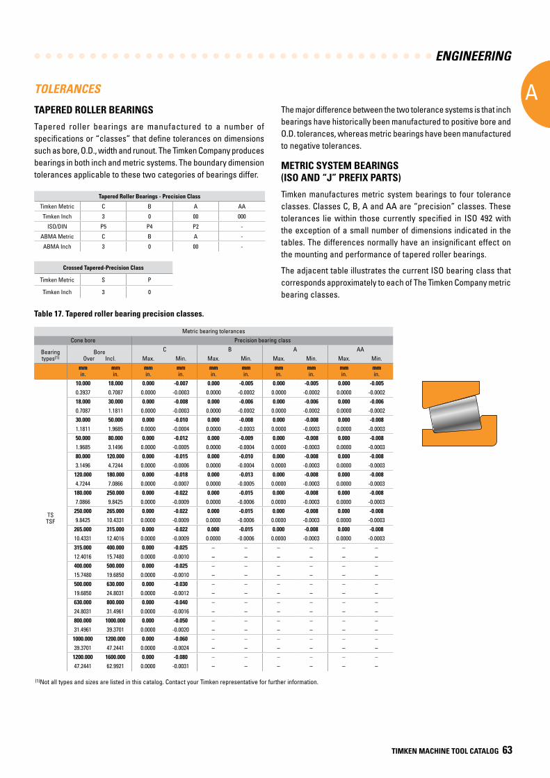
ENGINEERING
A
TIMKEN MACHINE TOOL CATALOG 63
TOLERANCES
TAPERED ROLLER BEARINGS
Tapered roller bearings are manufactured to a number of specifications or “classes” that define tolerances on dimensions such as bore, O.D., width and runout. The Timken Company produces bearings in both inch and metric systems. The boundary dimension tolerances applicable to these two categories of bearings differ.
The major difference between the two tolerance systems is that inch bearings have historically been manufactured to positive bore and O.D. tolerances, whereas metric bearings have been manufactured to negative tolerances.
METRIC SYSTEM BEARINGS (ISO AND “J” PREFIX PARTS)
Timken manufactures metric system bearings to four tolerance classes. Classes C, B, A and AA are “precision” classes. These tolerances lie within those currently specified in ISO 492 with the exception of a small number of dimensions indicated in the tables. The differences normally have an insignificant effect on the mounting and performance of tapered roller bearings.
The adjacent table illustrates the current ISO bearing class that corresponds approximately to each of The Timken Company metric bearing classes.
Tapered Roller Bearings - Precision Class
Timken Metric C B A AA
Timken Inch 3 0 00 000
ISO/DIN P5 P4 P2 -
ABMA Metric C B A -
ABMA Inch 3 0 00 -
Crossed Tapered-Precision Class
Timken Metric S P
Timken Inch 3 0
Metric bearing tolerancesCone bore Precision bearing class
Bearing types(1)
BoreOver Incl.
C B A AAMax. Min. Max. Min. Max. Min. Max. Min.
mmin.
mmin.
mmin.
mmin.
mmin.
mmin.
mmin.
mmin.
mmin.
mmin.
TSTSF
10.000 18.000 0.000 -0.007 0.000 -0.005 0.000 -0.005 0.000 -0.0050.3937 0.7087 0.0000 -0.0003 0.0000 -0.0002 0.0000 -0.0002 0.0000 -0.000218.000 30.000 0.000 -0.008 0.000 -0.006 0.000 -0.006 0.000 -0.0060.7087 1.1811 0.0000 -0.0003 0.0000 -0.0002 0.0000 -0.0002 0.0000 -0.000230.000 50.000 0.000 -0.010 0.000 -0.008 0.000 -0.008 0.000 -0.0081.1811 1.9685 0.0000 -0.0004 0.0000 -0.0003 0.0000 -0.0003 0.0000 -0.000350.000 80.000 0.000 -0.012 0.000 -0.009 0.000 -0.008 0.000 -0.0081.9685 3.1496 0.0000 -0.0005 0.0000 -0.0004 0.0000 -0.0003 0.0000 -0.000380.000 120.000 0.000 -0.015 0.000 -0.010 0.000 -0.008 0.000 -0.0083.1496 4.7244 0.0000 -0.0006 0.0000 -0.0004 0.0000 -0.0003 0.0000 -0.0003
120.000 180.000 0.000 -0.018 0.000 -0.013 0.000 -0.008 0.000 -0.0084.7244 7.0866 0.0000 -0.0007 0.0000 -0.0005 0.0000 -0.0003 0.0000 -0.0003
180.000 250.000 0.000 -0.022 0.000 -0.015 0.000 -0.008 0.000 -0.0087.0866 9.8425 0.0000 -0.0009 0.0000 -0.0006 0.0000 -0.0003 0.0000 -0.0003
250.000 265.000 0.000 -0.022 0.000 -0.015 0.000 -0.008 0.000 -0.0089.8425 10.4331 0.0000 -0.0009 0.0000 -0.0006 0.0000 -0.0003 0.0000 -0.0003
265.000 315.000 0.000 -0.022 0.000 -0.015 0.000 -0.008 0.000 -0.00810.4331 12.4016 0.0000 -0.0009 0.0000 -0.0006 0.0000 -0.0003 0.0000 -0.0003315.000 400.000 0.000 -0.025 – – – – – –12.4016 15.7480 0.0000 -0.0010 – – – – – –400.000 500.000 0.000 -0.025 – – – – – –15.7480 19.6850 0.0000 -0.0010 – – – – – –500.000 630.000 0.000 -0.030 – – – – – –19.6850 24.8031 0.0000 -0.0012 – – – – – –630.000 800.000 0.000 -0.040 – – – – – –24.8031 31.4961 0.0000 -0.0016 – – – – – –800.000 1000.000 0.000 -0.050 – – – – – –31.4961 39.3701 0.0000 -0.0020 – – – – – –
1000.000 1200.000 0.000 -0.060 – – – – – –39.3701 47.2441 0.0000 -0.0024 – – – – – –
1200.000 1600.000 0.000 -0.080 – – – – – –47.2441 62.9921 0.0000 -0.0031 – – – – – –
Table 17. Tapered roller bearing precision classes.
(1)Not all types and sizes are listed in this catalog. Contact your Timken representative for further information.
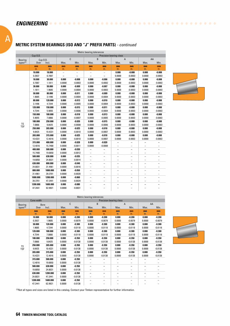
ENGINEERING
A
64 TIMKEN MACHINE TOOL CATALOG
METRIC SYSTEM BEARINGS (ISO AND “J” PREFIX PARTS) - continued
Metric bearing tolerancesCup O.D. Precision bearing class
Bearing types(1)
Cup O.D.Over Incl.
C B A AAMax. Min. Max. Min. Max. Min. Max. Min.
mmin.
mmin.
mmin.
mmin.
mmin.
mmin.
mmin.
mmin.
mmin.
mmin.
TSTSF
10.000 18.000 – – – – 0.000 -0.008 0.000 -0.0080.3937 0.7087 – – – – 0.0000 -0.0003 0.0000 -0.000318.000 30.000 0.000 -0.008 0.000 -0.006 0.000 -0.008 0.000 -0.0080.7087 1.1811 0.0000 -0.0003 0.0000 -0.0002 0.0000 -0.0003 0.0000 -0.000330.000 50.000 0.000 -0.009 0.000 -0.007 0.000 -0.008 0.000 -0.0081.1811 1.9685 0.0000 -0.0004 0.0000 -0.0003 0.0000 -0.0003 0.0000 -0.000350.000 80.000 0.000 -0.011 0.000 -0.009 0.000 -0.008 0.000 -0.0081.9685 3.1496 0.0000 -0.0004 0.0000 -0.0004 0.0000 -0.0003 0.0000 -0.000380.000 120.000 0.000 -0.013 0.000 -0.010 0.000 -0.008 0.000 -0.0083.1496 4.7244 0.0000 -0.0005 0.0000 -0.0004 0.0000 -0.0003 0.0000 -0.0003
120.000 150.000 0.000 -0.015 0.000 -0.011 0.000 -0.008 0.000 -0.0084.7244 5.9055 0.0000 -0.0006 0.0000 -0.0004 0.0000 -0.0003 0.0000 -0.0003
150.000 180.000 0.000 -0.018 0.000 -0.013 0.000 -0.008 0.000 -0.0085.9055 7.0866 0.0000 -0.0007 0.0000 -0.0005 0.0000 -0.0003 0.0000 -0.0003
180.000 250.000 0.000 -0.020 0.000 -0.015 0.000 -0.008 0.000 -0.0087.0866 9.8425 0.0000 -0.0008 0.0000 -0.0006 0.0000 -0.0003 0.0000 -0.0003
250.000 265.000 0.000 -0.025 0.000 -0.018 0.000 -0.008 0.000 -0.0089.8425 10.4331 0.0000 -0.0010 0.0000 -0.0007 0.0000 -0.0003 0.0000 -0.0003
265.000 315.000 0.000 -0.025 0.000 -0.018 0.000 -0.008 0.000 -0.00810.4331 12.4016 0.0000 -0.0010 0.0000 -0.0007 0.0000 -0.0003 0.0000 -0.0003315.000 400.000 0.000 -0.028 0.000 -0.020 – – – –12.4016 15.7480 0.0000 -0.0011 0.0000 -0.0008 – – – –400.000 500.000 0.000 -0.030 – – – – – –15.7480 19.6850 0.0000 -0.0012 – – – – – –500.000 630.000 0.000 -0.035 – – – – – –19.6850 24.8031 0.0000 -0.0014 – – – – – –630.000 800.000 0.000 -0.040 – – – – – –24.8031 31.4961 0.0000 -0.0016 – – – – – –800.000 1000.000 0.000 -0.050 – – – – – –31.4961 39.3701 0.0000 -0.0020 – – – – – –
1000.000 1200.000 0.000 -0.060 – – – – – –39.3701 47.2441 0.0000 -0.0024 – – – – – –
1200.000 1600.000 0.000 -0.080 – – – – – –47.2441 62.9921 0.0000 -0.0031 – – – – – –
Metric bearing tolerancesCone width Precision bearing class
Bearing types(1)
BoreOver Incl.
C B A AAMax. Min. Max. Min. Max. Min. Max. Min.
mmin.
mmin.
mmin.
mmin.
mmin.
mmin.
mmin.
mmin.
mmin.
mmin.
TSTSF
10.000 50.000 0.000 -0.200 0.000 -0.200 0.000 -0.200 0.000 -0.2000.3937 1.9685 0.0000 -0.0079 0.0000 -0.0079 0.0000 -0.0079 0.0000 -0.007950.000 120.000 0.000 -0.300 0.000 -0.300 0.000 -0.300 0.000 -0.3001.9685 4.7244 0.0000 -0.0118 0.0000 -0.0118 0.0000 -0.0118 0.0000 -0.0118
120.000 180.000 0.000 -0.300 0.000 -0.300 0.000 -0.300 0.000 -0.3004.7244 7.0866 0.0000 -0.0118 0.0000 -0.0118 0.0000 -0.0118 0.0000 -0.0118
180.000 250.000 0.000 -0.350 0.000 -0.350 0.000 -0.350 0.000 -0.3507.0866 9.8425 0.0000 -0.0138 0.0000 -0.0138 0.0000 -0.0138 0.0000 -0.0138
250.000 265.000 0.000 -0.350 0.000 -0.350 0.000 -0.350 0.000 -0.3509.8425 10.4331 0.0000 -0.0138 0.0000 -0.0138 0.0000 -0.0138 0.0000 -0.0138
265.000 315.000 0.000 -0.350 0.000 -0.350 0.000 -0.350 0.000 -0.35010.4331 12.4016 0.0000 -0.0138 0.0000 -0.0138 0.0000 -0.0138 0.0000 -0.0138315.000 500.000 0.000 -0.350 – – – – – –12.4016 19.6850 0.0000 -0.0138 – – – – – –500.000 630.000 0.000 -0.350 – – – – – –19.6850 24.8031 0.0000 -0.0138 – – – – – –630.000 1200.000 0.000 -0.350 – – – – – –24.8031 47.2441 0.0000 -0.0138 – – – – – –
1200.000 1600.000 0.000 -0.350 – – – – – –47.2441 62.9921 0.0000 -0.0138 – – – – – –
(1)Not all types and sizes are listed in this catalog. Contact your Timken representative for further information.
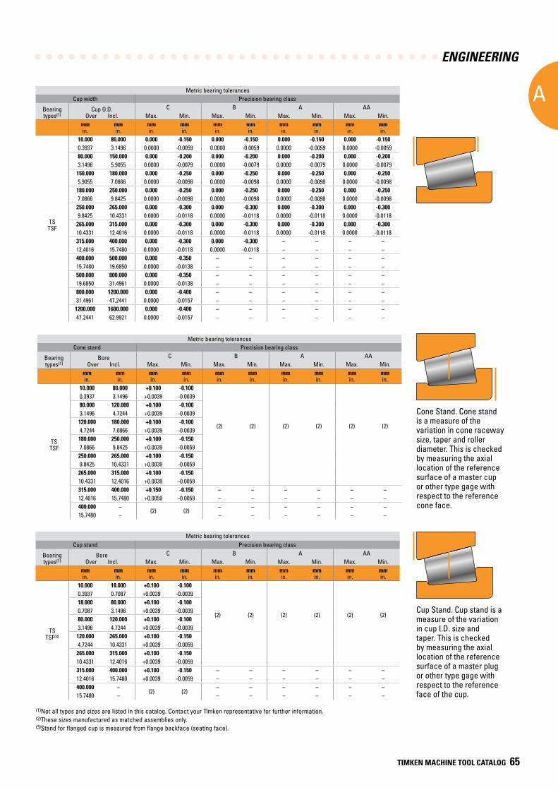
ENGINEERING
A
TIMKEN MACHINE TOOL CATALOG 65
Metric bearing tolerancesCone stand Precision bearing class
Bearing types(1)
BoreOver Incl.
C B A AAMax. Min. Max. Min. Max. Min. Max. Min.
mmin.
mmin.
mmin.
mmin.
mmin.
mmin.
mmin.
mmin.
mmin.
mmin.
TSTSF
10.000 80.000 +0.100 -0.100
(2) (2) (2) (2) (2) (2)
0.3937 3.1496 +0.0039 -0.003980.000 120.000 +0.100 -0.1003.1496 4.7244 +0.0039 -0.0039
120.000 180.000 +0.100 -0.1004.7244 7.0866 +0.0039 -0.0039
180.000 250.000 +0.100 -0.1507.0866 9.8425 +0.0039 -0.0059
250.000 265.000 +0.100 -0.1509.8425 10.4331 +0.0039 -0.0059
265.000 315.000 +0.100 -0.15010.4331 12.4016 +0.0039 -0.0059315.000 400.000 +0.150 -0.150 – – – – – –12.4016 15.7480 +0.0059 -0.0059 – – – – – –400.000 –
(2) (2)– – – – – –
15.7480 – – – – – – –
Metric bearing tolerancesCup width Precision bearing class
Bearing types(1)
Cup O.D.Over Incl.
C B A AAMax. Min. Max. Min. Max. Min. Max. Min.
mmin.
mmin.
mmin.
mmin.
mmin.
mmin.
mmin.
mmin.
mmin.
mmin.
TSTSF
10.000 80.000 0.000 -0.150 0.000 -0.150 0.000 -0.150 0.000 -0.1500.3937 3.1496 0.0000 -0.0059 0.0000 -0.0059 0.0000 -0.0059 0.0000 -0.005980.000 150.000 0.000 -0.200 0.000 -0.200 0.000 -0.200 0.000 -0.2003.1496 5.9055 0.0000 -0.0079 0.0000 -0.0079 0.0000 -0.0079 0.0000 -0.0079
150.000 180.000 0.000 -0.250 0.000 -0.250 0.000 -0.250 0.000 -0.2505.9055 7.0866 0.0000 -0.0098 0.0000 -0.0098 0.0000 -0.0098 0.0000 -0.0098
180.000 250.000 0.000 -0.250 0.000 -0.250 0.000 -0.250 0.000 -0.2507.0866 9.8425 0.0000 -0.0098 0.0000 -0.0098 0.0000 -0.0098 0.0000 -0.0098
250.000 265.000 0.000 -0.300 0.000 -0.300 0.000 -0.300 0.000 -0.3009.8425 10.4331 0.0000 -0.0118 0.0000 -0.0118 0.0000 -0.0118 0.0000 -0.0118
265.000 315.000 0.000 -0.300 0.000 -0.300 0.000 -0.300 0.000 -0.30010.4331 12.4016 0.0000 -0.0118 0.0000 -0.0118 0.0000 -0.0118 0.0000 -0.0118315.000 400.000 0.000 -0.300 0.000 -0.300 – – – –12.4016 15.7480 0.0000 -0.0118 0.0000 -0.0118 – – – –400.000 500.000 0.000 -0.350 – – – – – –15.7480 19.6850 0.0000 -0.0138 – – – – – –500.000 800.000 0.000 -0.350 – – – – – –19.6850 31.4961 0.0000 -0.0138 – – – – – –800.000 1200.000 0.000 -0.400 – – – – – –31.4961 47.2441 0.0000 -0.0157 – – – – – –
1200.000 1600.000 0.000 -0.400 – – – – – –47.2441 62.9921 0.0000 -0.0157 – – – – – –
(1)Not all types and sizes are listed in this catalog. Contact your Timken representative for further information.(2)These sizes manufactured as matched assemblies only.(3)Stand for flanged cup is measured from flange backface (seating face).
Metric bearing tolerancesCup stand Precision bearing class
Bearing types(1)
BoreOver Incl.
C B A AAMax. Min. Max. Min. Max. Min. Max. Min.
mmin.
mmin.
mmin.
mmin.
mmin.
mmin.
mmin.
mmin.
mmin.
mmin.
TSTSF(3)
10.000 18.000 +0.100 -0.100
(2) (2) (2) (2) (2) (2)
0.3937 0.7087 +0.0039 -0.003918.000 80.000 +0.100 -0.1000.7087 3.1496 +0.0039 -0.003980.000 120.000 +0.100 -0.1003.1496 4.7244 +0.0039 -0.0039
120.000 265.000 +0.100 -0.1504.7244 10.4331 +0.0039 -0.0059
265.000 315.000 +0.100 -0.15010.4331 12.4016 +0.0039 -0.0059315.000 400.000 +0.100 -0.150 – – – – – –12.4016 15.7480 +0.0039 -0.0059 – – – – – –400.000 –
(2) (2)– – – – – –
15.7480 – – – – – – –
Cone Stand. Cone stand is a measure of the variation in cone raceway size, taper and roller diameter. This is checked by measuring the axial location of the reference surface of a master cup or other type gage with respect to the reference cone face.
Cup Stand. Cup stand is a measure of the variation in cup I.D. size and taper. This is checked by measuring the axial location of the reference surface of a master plug or other type gage with respect to the reference face of the cup.
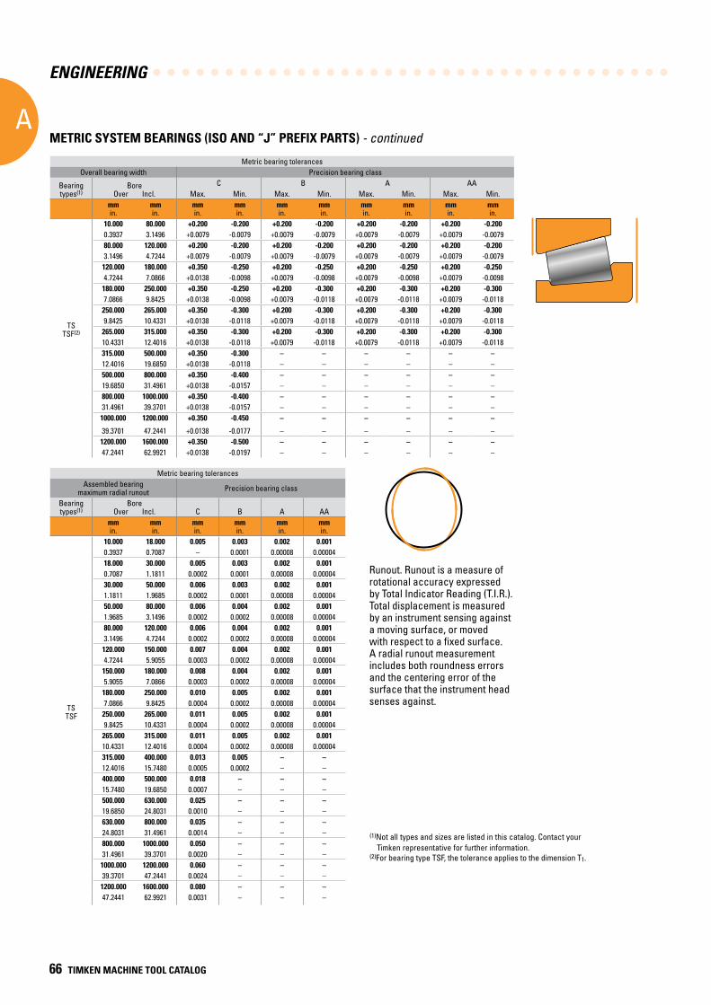
ENGINEERING
A
66 TIMKEN MACHINE TOOL CATALOG
Metric bearing tolerancesOverall bearing width Precision bearing class
Bearing types(1)
BoreOver Incl.
C B A AAMax. Min. Max. Min. Max. Min. Max. Min.
mmin.
mmin.
mmin.
mmin.
mmin.
mmin.
mmin.
mmin.
mmin.
mmin.
TSTSF(2)
10.000 80.000 +0.200 -0.200 +0.200 -0.200 +0.200 -0.200 +0.200 -0.2000.3937 3.1496 +0.0079 -0.0079 +0.0079 -0.0079 +0.0079 -0.0079 +0.0079 -0.007980.000 120.000 +0.200 -0.200 +0.200 -0.200 +0.200 -0.200 +0.200 -0.2003.1496 4.7244 +0.0079 -0.0079 +0.0079 -0.0079 +0.0079 -0.0079 +0.0079 -0.0079
120.000 180.000 +0.350 -0.250 +0.200 -0.250 +0.200 -0.250 +0.200 -0.2504.7244 7.0866 +0.0138 -0.0098 +0.0079 -0.0098 +0.0079 -0.0098 +0.0079 -0.0098
180.000 250.000 +0.350 -0.250 +0.200 -0.300 +0.200 -0.300 +0.200 -0.3007.0866 9.8425 +0.0138 -0.0098 +0.0079 -0.0118 +0.0079 -0.0118 +0.0079 -0.0118
250.000 265.000 +0.350 -0.300 +0.200 -0.300 +0.200 -0.300 +0.200 -0.3009.8425 10.4331 +0.0138 -0.0118 +0.0079 -0.0118 +0.0079 -0.0118 +0.0079 -0.0118
265.000 315.000 +0.350 -0.300 +0.200 -0.300 +0.200 -0.300 +0.200 -0.30010.4331 12.4016 +0.0138 -0.0118 +0.0079 -0.0118 +0.0079 -0.0118 +0.0079 -0.0118315.000 500.000 +0.350 -0.300 – – – – – –12.4016 19.6850 +0.0138 -0.0118 – – – – – –500.000 800.000 +0.350 -0.400 – – – – – –19.6850 31.4961 +0.0138 -0.0157 – – – – – –800.000 1000.000 +0.350 -0.400 – – – – – –31.4961 39.3701 +0.0138 -0.0157 – – – – – –
1000.000 1200.000 +0.350 -0.450 – – – – – –
39.3701 47.2441 +0.0138 -0.0177 – – – – – –1200.000 1600.000 +0.350 -0.500 – – – – – –47.2441 62.9921 +0.0138 -0.0197 – – – – – –
Metric bearing tolerancesAssembled bearing
maximum radial runout Precision bearing class
Bearing types(1)
BoreOver Incl. C B A AA
mmin.
mmin.
mmin.
mmin.
mmin.
mmin.
TSTSF
10.000 18.000 0.005 0.003 0.002 0.0010.3937 0.7087 – 0.0001 0.00008 0.0000418.000 30.000 0.005 0.003 0.002 0.0010.7087 1.1811 0.0002 0.0001 0.00008 0.0000430.000 50.000 0.006 0.003 0.002 0.0011.1811 1.9685 0.0002 0.0001 0.00008 0.0000450.000 80.000 0.006 0.004 0.002 0.0011.9685 3.1496 0.0002 0.0002 0.00008 0.0000480.000 120.000 0.006 0.004 0.002 0.0013.1496 4.7244 0.0002 0.0002 0.00008 0.00004
120.000 150.000 0.007 0.004 0.002 0.0014.7244 5.9055 0.0003 0.0002 0.00008 0.00004
150.000 180.000 0.008 0.004 0.002 0.0015.9055 7.0866 0.0003 0.0002 0.00008 0.00004
180.000 250.000 0.010 0.005 0.002 0.0017.0866 9.8425 0.0004 0.0002 0.00008 0.00004
250.000 265.000 0.011 0.005 0.002 0.0019.8425 10.4331 0.0004 0.0002 0.00008 0.00004
265.000 315.000 0.011 0.005 0.002 0.00110.4331 12.4016 0.0004 0.0002 0.00008 0.00004315.000 400.000 0.013 0.005 – –12.4016 15.7480 0.0005 0.0002 – –400.000 500.000 0.018 – – –15.7480 19.6850 0.0007 – – –500.000 630.000 0.025 – – –19.6850 24.8031 0.0010 – – –630.000 800.000 0.035 – – –24.8031 31.4961 0.0014 – – –800.000 1000.000 0.050 – – –31.4961 39.3701 0.0020 – – –
1000.000 1200.000 0.060 – – –39.3701 47.2441 0.0024 – – –
1200.000 1600.000 0.080 – – –47.2441 62.9921 0.0031 – – –
(1)Not all types and sizes are listed in this catalog. Contact your Timken representative for further information.
(2)For bearing type TSF, the tolerance applies to the dimension T1.
Runout. Runout is a measure of rotational accuracy expressed by Total Indicator Reading (T.I.R.). Total displacement is measured by an instrument sensing against a moving surface, or moved with respect to a fixed surface. A radial runout measurement includes both roundness errors and the centering error of the surface that the instrument head senses against.
METRIC SYSTEM BEARINGS (ISO AND “J” PREFIX PARTS) - continued
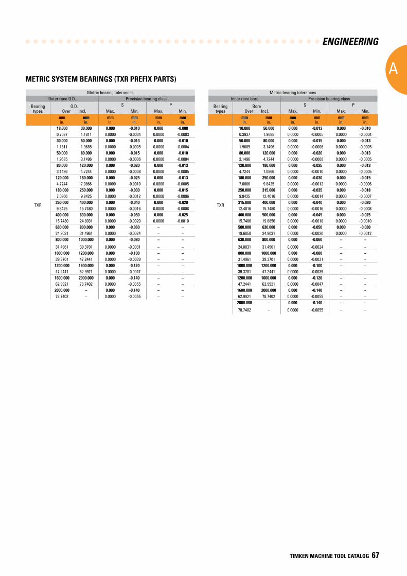
ENGINEERING
A
TIMKEN MACHINE TOOL CATALOG 67
Metric bearing tolerancesOuter race O.D. Precision bearing class
Bearing types
O.D.Over Incl.
S PMax. Min. Max. Min.
mmin.
mmin.
mmin.
mmin.
mmin.
mmin.
TXR
18.000 30.000 0.000 -0.010 0.000 -0.0080.7087 1.1811 0.0000 -0.0004 0.0000 -0.000330.000 50.000 0.000 -0.013 0.000 -0.0101.1811 1.9685 0.0000 -0.0005 0.0000 -0.000450.000 80.000 0.000 -0.015 0.000 -0.0101.9685 3.1496 0.0000 -0.0006 0.0000 -0.000480.000 120.000 0.000 -0.020 0.000 -0.0133.1496 4.7244 0.0000 -0.0008 0.0000 -0.0005
120.000 180.000 0.000 -0.025 0.000 -0.0134.7244 7.0866 0.0000 -0.0010 0.0000 -0.0005
180.000 250.000 0.000 -0.030 0.000 -0.0157.0866 9.8425 0.0000 -0.0012 0.0000 -0.0006
250.000 400.000 0.000 -0.040 0.000 -0.0209.8425 15.7480 0.0000 -0.0016 0.0000 -0.0008
400.000 630.000 0.000 -0.050 0.000 -0.02515.7480 24.8031 0.0000 -0.0020 0.0000 -0.0010630.000 800.000 0.000 -0.060 – –24.8031 31.4961 0.0000 -0.0024 – –800.000 1000.000 0.000 -0.080 – –
31.4961 39.3701 0.0000 -0.0031 – –1000.000 1200.000 0.000 -0.100 – –39.3701 47.2441 0.0000 -0.0039 – –
1200.000 1600.000 0.000 -0.120 – –47.2441 62.9921 0.0000 -0.0047 – –
1600.000 2000.000 0.000 -0.140 – –62.9921 78.7402 0.0000 -0.0055 – –
2000.000 – 0.000 -0.140 – –78.7402 – 0.0000 -0.0055 – –
METRIC SYSTEM BEARINGS (TXR PREFIX PARTS)
Metric bearing tolerancesInner race bore Precision bearing class
Bearing types
BoreOver Incl.
S PMax. Min. Max. Min.
mmin.
mmin.
mmin.
mmin.
mmin.
mmin.
TXR
10.000 50.000 0.000 -0.013 0.000 -0.0100.3937 1.9685 0.0000 -0.0005 0.0000 -0.000450.000 80.000 0.000 -0.015 0.000 -0.0131.9685 3.1496 0.0000 -0.0006 0.0000 -0.000580.000 120.000 0.000 -0.020 0.000 -0.0133.1496 4.7244 0.0000 -0.0008 0.0000 -0.0005
120.000 180.000 0.000 -0.025 0.000 -0.0134.7244 7.0866 0.0000 -0.0010 0.0000 -0.0005
180.000 250.000 0.000 -0.030 0.000 -0.0157.0866 9.8425 0.0000 -0.0012 0.0000 -0.0006
250.000 315.000 0.000 -0.035 0.000 -0.0189.8425 12.4016 0.0000 -0.0014 0.0000 -0.0007
315.000 400.000 0.000 -0.040 0.000 -0.02012.4016 15.7480 0.0000 -0.0016 0.0000 -0.0008400.000 500.000 0.000 -0.045 0.000 -0.02515.7480 19.6850 0.0000 -0.0018 0.0000 -0.0010500.000 630.000 0.000 -0.050 0.000 -0.03019.6850 24.8031 0.0000 -0.0020 0.0000 -0.0012630.000 800.000 0.000 -0.060 – –
24.8031 31.4961 0.0000 -0.0024 – –800.000 1000.000 0.000 -0.080 – –31.4961 39.3701 0.0000 -0.0031 – –
1000.000 1200.000 0.000 -0.100 – –39.3701 47.2441 0.0000 -0.0039 – –
1200.000 1600.000 0.000 -0.120 – –47.2441 62.9921 0.0000 -0.0047 – –
1600.000 2000.000 0.000 -0.140 – –62.9921 78.7402 0.0000 -0.0055 – –
2000.000 – 0.000 -0.140 – –
78.7402 – 0.0000 -0.0055 – –
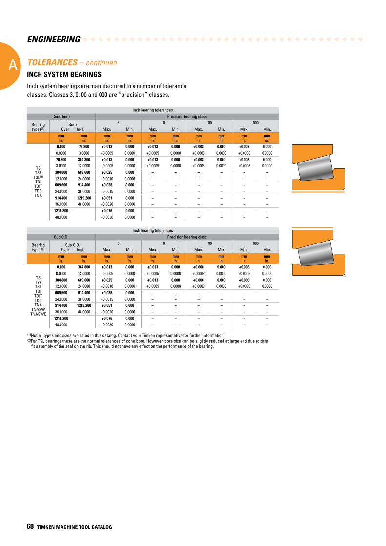
ENGINEERING
A
68 TIMKEN MACHINE TOOL CATALOG
(1)Not all types and sizes are listed in this catalog. Contact your Timken representative for further information.(2)For TSL bearings these are the normal tolerances of cone bore. However, bore size can be slightly reduced at large end due to tight
fit assembly of the seal on the rib. This should not have any effect on the performance of the bearing.
TOLERANCES – continuedINCH SYSTEM BEARINGS
Inch system bearings are manufactured to a number of tolerance classes. Classes 3, 0, 00 and 000 are “precision” classes.
Inch bearing tolerancesCone bore Precision bearing class
Bearing types(1)
BoreOver Incl.
3 0 00 000Max. Min. Max. Min. Max. Min. Max. Min.
mmin.
mmin.
mmin.
mmin.
mmin.
mmin.
mmin.
mmin.
mmin.
mmin.
TSTSF
TSL(2)
TDITDITTDOTNA
0.000 76.200 +0.013 0.000 +0.013 0.000 +0.008 0.000 +0.008 0.0000.0000 3.0000 +0.0005 0.0000 +0.0005 0.0000 +0.0003 0.0000 +0.0003 0.000076.200 304.800 +0.013 0.000 +0.013 0.000 +0.008 0.000 +0.008 0.0003.0000 12.0000 +0.0005 0.0000 +0.0005 0.0000 +0.0003 0.0000 +0.0003 0.0000304.800 609.600 +0.025 0.000 – – – – – –12.0000 24.0000 +0.0010 0.0000 – – – – – –609.600 914.400 +0.038 0.000 – – – – – –24.0000 36.0000 +0.0015 0.0000 – – – – – –914.400 1219.200 +0.051 0.000 – – – – – –36.0000 48.0000 +0.0020 0.0000 – – – – – –1219.200 +0.076 0.000 – – – – – –48.0000 +0.0030 0.0000 – – – – – –
Inch bearing tolerancesCup O.D. Precision bearing class
Bearing types(1)
Cup O.D.Over Incl.
3 0 00 000Max. Min. Max. Min. Max. Min. Max. Min.
mmin.
mmin.
mmin.
mmin.
mmin.
mmin.
mmin.
mmin.
mmin.
mmin.
TSTSFTSLTDI
TDITTDOTNA
TNASWTNASWE
0.000 304.800 +0.013 0.000 +0.013 0.000 +0.008 0.000 +0.008 0.0000.0000 12.0000 +0.0005 0.0000 +0.0005 0.0000 +0.0003 0.0000 +0.0003 0.0000304.800 609.600 +0.025 0.000 +0.013 0.000 +0.008 0.000 +0.008 0.00012.0000 24.0000 +0.0010 0.0000 +0.0005 0.0000 +0.0003 0.0000 +0.0003 0.0000609.600 914.400 +0.038 0.000 – – – – – –24.0000 36.0000 +0.0015 0.0000 – – – – – –914.400 1219.200 +0.051 0.000 – – – – – –36.0000 48.0000 +0.0020 0.0000 – – – – – –1219.200 +0.076 0.000 – – – – – –48.0000 +0.0030 0.0000 – – – – – –
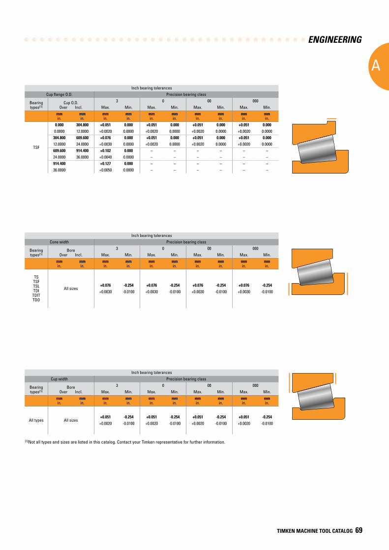
ENGINEERING
A
TIMKEN MACHINE TOOL CATALOG 69
Inch bearing tolerancesCup flange O.D. Precision bearing class
Bearing types(1)
Cup O.D.Over Incl.
3 0 00 000Max. Min. Max. Min. Max. Min. Max. Min.
mmin.
mmin.
mmin.
mmin.
mmin.
mmin.
mmin.
mmin.
mmin.
mmin.
TSF
0.000 304.800 +0.051 0.000 +0.051 0.000 +0.051 0.000 +0.051 0.0000.0000 12.0000 +0.0020 0.0000 +0.0020 0.0000 +0.0020 0.0000 +0.0020 0.0000304.800 609.600 +0.076 0.000 +0.051 0.000 +0.051 0.000 +0.051 0.00012.0000 24.0000 +0.0030 0.0000 +0.0020 0.0000 +0.0020 0.0000 +0.0020 0.0000609.600 914.400 +0.102 0.000 – – – – – –24.0000 36.0000 +0.0040 0.0000 – – – – – –914.400 +0.127 0.000 – – – – – –36.0000 +0.0050 0.0000 – – – – – –
Inch bearing tolerancesCone width Precision bearing class
Bearing types(1)
BoreOver Incl.
3 0 00 000Max. Min. Max. Min. Max. Min. Max. Min.
mmin.
mmin.
mmin.
mmin.
mmin.
mmin.
mmin.
mmin.
mmin.
mmin.
TSTSFTSLTDI
TDITTDO
All sizes+0.076 -0.254 +0.076 -0.254 +0.076 -0.254 +0.076 -0.254
+0.0030 -0.0100 +0.0030 -0.0100 +0.0030 -0.0100 +0.0030 -0.0100
Inch bearing tolerancesCup width Precision bearing class
Bearing types(1)
BoreOver Incl.
3 0 00 000Max. Min. Max. Min. Max. Min. Max. Min.
mmin.
mmin.
mmin.
mmin.
mmin.
mmin.
mmin.
mmin.
mmin.
mmin.
All types All sizes+0.051 -0.254 +0.051 -0.254 +0.051 -0.254 +0.051 -0.254
+0.0020 -0.0100 +0.0020 -0.0100 +0.0020 -0.0100 +0.0020 -0.0100
(1)Not all types and sizes are listed in this catalog. Contact your Timken representative for further information.
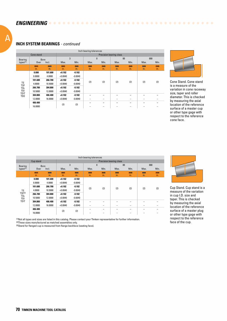
ENGINEERING
A
70 TIMKEN MACHINE TOOL CATALOG
(1)Not all types and sizes are listed in this catalog. Please contact your Timken representative for further information.(2)These sizes manufactured as matched assemblies only. (3)Stand for flanged cup is measured from flange backface (seating face).
Inch bearing tolerancesCone stand Precision bearing class
Bearing types(1)
BoreOver Incl.
3 0 00 000Max. Min. Max. Min. Max. Min. Max. Min.
mmin.
mmin.
mmin.
mmin.
mmin.
mmin.
mmin.
mmin.
mmin.
mmin.
TSTSFTSLTDI
TDITTDO
0.000 101.600 +0.102 -0.102
(2) (2) (2) (2) (2) (2)
0.0000 4.0000 +0.0040 -0.0040101.600 266.700 +0.102 -0.1024.0000 10.5000 +0.0040 -0.0040
266.700 304.800 +0.102 -0.10210.5000 12.0000 +0.0040 -0.0040304.800 406.400 +0.102 -0.102 – – – – – –12.0000 16.0000 +0.0040 -0.0040 – – – – – –406.400
(2) (2)– – – – – –
16.0000 – – – – – –
Inch bearing tolerancesCup stand Precision bearing class
Bearing types(1)
BoreOver Incl.
3 0 00 000Max. Min. Max. Min. Max. Min. Max. Min.
mmin.
mmin.
mmin.
mmin.
mmin.
mmin.
mmin.
mmin.
mmin.
mmin.
TSTSF(3)
TSLTDI
TDIT
0.000 101.600 +0.102 -0.102
(2) (2) (2) (2) (2) (2)
0.0000 4.0000 +0.0040 -0.0040101.600 266.700 +0.102 -0.1024.0000 10.5000 +0.0040 -0.0040
266.700 304.800 +0.102 -0.10210.5000 12.0000 +0.0040 -0.0040304.800 406.400 +0.102 -0.102 – – – – – –12.0000 16.0000 +0.0040 -0.0040 – – – – – –406.400
(2) (2)– – – – – –
16.0000 – – – – – –
Cone Stand. Cone stand is a measure of the variation in cone raceway size, taper and roller diameter. This is checked by measuring the axial location of the reference surface of a master cup or other type gage with respect to the reference cone face.
Cup Stand. Cup stand is a measure of the variation in cup I.D. size and taper. This is checked by measuring the axial location of the reference surface of a master plug or other type gage with respect to the reference face of the cup.
INCH SYSTEM BEARINGS - continued
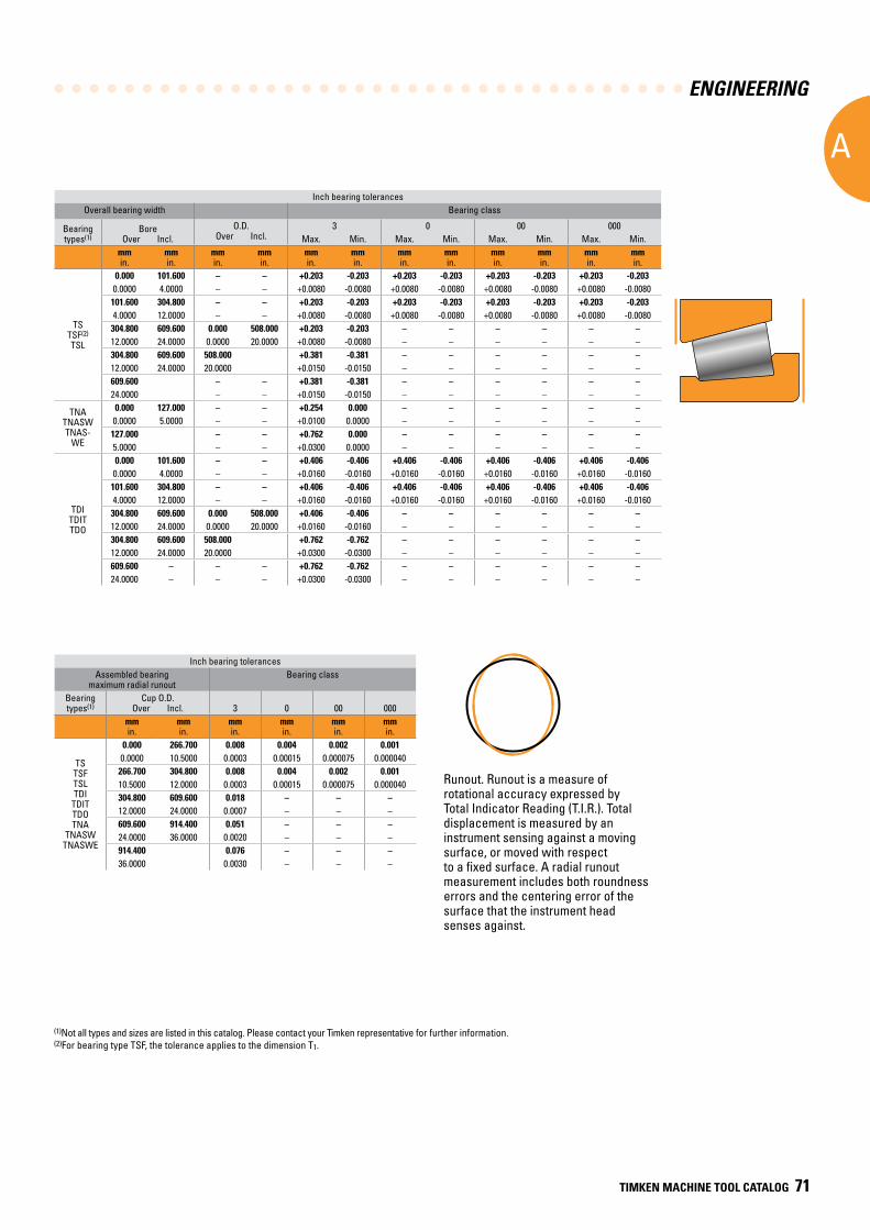
ENGINEERING
A
TIMKEN MACHINE TOOL CATALOG 71
Inch bearing tolerancesOverall bearing width Bearing class
Bearing types(1)
BoreOver Incl.
O.D.Over Incl.
3 0 00 000Max. Min. Max. Min. Max. Min. Max. Min.
mmin.
mmin.
mmin.
mmin.
mmin.
mmin.
mmin.
mmin.
mmin.
mmin.
mmin.
mmin.
TSTSF(2)
TSL
0.000 101.600 – – +0.203 -0.203 +0.203 -0.203 +0.203 -0.203 +0.203 -0.2030.0000 4.0000 – – +0.0080 -0.0080 +0.0080 -0.0080 +0.0080 -0.0080 +0.0080 -0.0080
101.600 304.800 – – +0.203 -0.203 +0.203 -0.203 +0.203 -0.203 +0.203 -0.2034.0000 12.0000 – – +0.0080 -0.0080 +0.0080 -0.0080 +0.0080 -0.0080 +0.0080 -0.0080
304.800 609.600 0.000 508.000 +0.203 -0.203 – – – – – –12.0000 24.0000 0.0000 20.0000 +0.0080 -0.0080 – – – – – –304.800 609.600 508.000 +0.381 -0.381 – – – – – –12.0000 24.0000 20.0000 +0.0150 -0.0150 – – – – – –609.600 – – +0.381 -0.381 – – – – – –24.0000 – – +0.0150 -0.0150 – – – – – –
TNATNASWTNAS-
WE
0.000 127.000 – – +0.254 0.000 – – – – – –0.0000 5.0000 – – +0.0100 0.0000 – – – – – –127.000 – – +0.762 0.000 – – – – – –5.0000 – – +0.0300 0.0000 – – – – – –
TDITDITTDO
0.000 101.600 – – +0.406 -0.406 +0.406 -0.406 +0.406 -0.406 +0.406 -0.4060.0000 4.0000 – – +0.0160 -0.0160 +0.0160 -0.0160 +0.0160 -0.0160 +0.0160 -0.0160
101.600 304.800 – – +0.406 -0.406 +0.406 -0.406 +0.406 -0.406 +0.406 -0.4064.0000 12.0000 – – +0.0160 -0.0160 +0.0160 -0.0160 +0.0160 -0.0160 +0.0160 -0.0160
304.800 609.600 0.000 508.000 +0.406 -0.406 – – – – – –12.0000 24.0000 0.0000 20.0000 +0.0160 -0.0160 – – – – – –304.800 609.600 508.000 +0.762 -0.762 – – – – – –12.0000 24.0000 20.0000 +0.0300 -0.0300 – – – – – –609.600 – – – +0.762 -0.762 – – – – – –24.0000 – – – +0.0300 -0.0300 – – – – – –
Inch bearing tolerancesAssembled bearing
maximum radial runoutBearing class
Bearing types(1)
Cup O.D.Over Incl. 3 0 00 000
mmin.
mmin.
mmin.
mmin.
mmin.
mmin.
TSTSFTSLTDI
TDITTDOTNA
TNASWTNASWE
0.000 266.700 0.008 0.004 0.002 0.0010.0000 10.5000 0.0003 0.00015 0.000075 0.000040
266.700 304.800 0.008 0.004 0.002 0.00110.5000 12.0000 0.0003 0.00015 0.000075 0.000040304.800 609.600 0.018 – – –12.0000 24.0000 0.0007 – – –609.600 914.400 0.051 – – –24.0000 36.0000 0.0020 – – –914.400 0.076 – – –36.0000 0.0030 – – –
Runout. Runout is a measure of rotational accuracy expressed by Total Indicator Reading (T.I.R.). Total displacement is measured by an instrument sensing against a moving surface, or moved with respect to a fixed surface. A radial runout measurement includes both roundness errors and the centering error of the surface that the instrument head senses against.
(1)Not all types and sizes are listed in this catalog. Please contact your Timken representative for further information.(2)For bearing type TSF, the tolerance applies to the dimension T1.
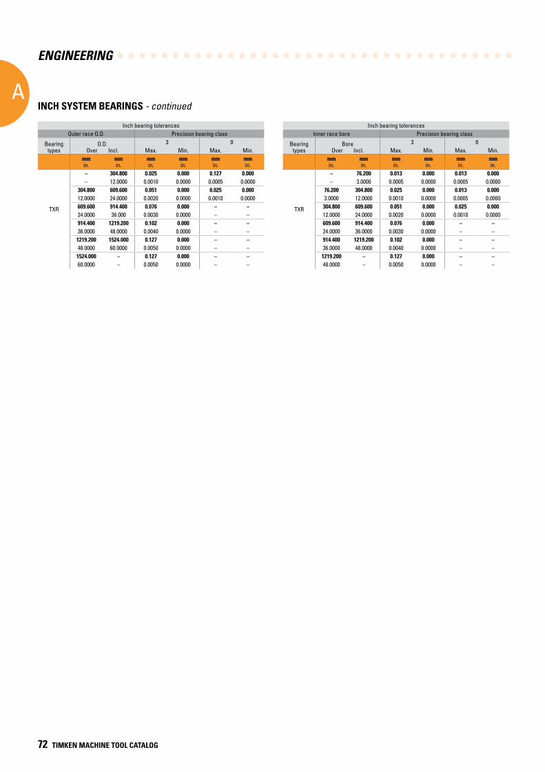
ENGINEERING
A
72 TIMKEN MACHINE TOOL CATALOG
INCH SYSTEM BEARINGS - continued
Inch bearing tolerancesOuter race O.D. Precision bearing class
Bearing types
O.D.Over Incl.
3 0Max. Min. Max. Min.
mmin.
mmin.
mmin.
mmin.
mmin.
mmin.
TXR
– 304.800 0.025 0.000 0.127 0.000– 12.0000 0.0010 0.0000 0.0005 0.0000
304.800 609.600 0.051 0.000 0.025 0.00012.0000 24.0000 0.0020 0.0000 0.0010 0.0000609.600 914.400 0.076 0.000 – –24.0000 36.000 0.0030 0.0000 – –914.400 1219.200 0.102 0.000 – –36.0000 48.0000 0.0040 0.0000 – –
1219.200 1524.000 0.127 0.000 – –48.0000 60.0000 0.0050 0.0000 – –
1524.000 – 0.127 0.000 – –60.0000 – 0.0050 0.0000 – –
Inch bearing tolerancesInner race bore Precision bearing class
Bearing types
BoreOver Incl.
3 0Max. Min. Max. Min.
mmin.
mmin.
mmin.
mmin.
mmin.
mmin.
TXR
– 76.200 0.013 0.000 0.013 0.000– 3.0000 0.0005 0.0000 0.0005 0.0000
76.200 304.800 0.025 0.000 0.013 0.0003.0000 12.0000 0.0010 0.0000 0.0005 0.0000304.800 609.600 0.051 0.000 0.025 0.00012.0000 24.0000 0.0020 0.0000 0.0010 0.0000609.600 914.400 0.076 0.000 – –24.0000 36.0000 0.0030 0.0000 – –914.400 1219.200 0.102 0.000 – –36.0000 48.0000 0.0040 0.0000 – –1219.200 – 0.127 0.000 – –48.0000 – 0.0050 0.0000 – –
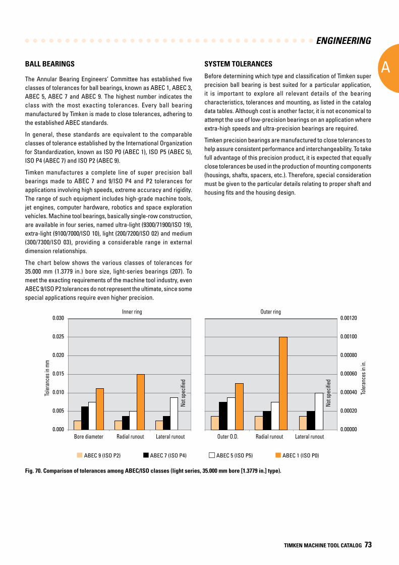
ENGINEERING
A
TIMKEN MACHINE TOOL CATALOG 73
BALL BEARINGS
The Annular Bearing Engineers’ Committee has established five classes of tolerances for ball bearings, known as ABEC 1, ABEC 3, ABEC 5, ABEC 7 and ABEC 9. The highest number indicates the class with the most exacting tolerances. Every ball bearing manufactured by Timken is made to close tolerances, adhering to the established ABEC standards.
In general, these standards are equivalent to the comparable classes of tolerance established by the International Organization for Standardization, known as ISO P0 (ABEC 1), ISO P5 (ABEC 5), ISO P4 (ABEC 7) and ISO P2 (ABEC 9).
Timken manufactures a complete line of super precision ball bearings made to ABEC 7 and 9/ISO P4 and P2 tolerances for applications involving high speeds, extreme accuracy and rigidity. The range of such equipment includes high-grade machine tools, jet engines, computer hardware, robotics and space exploration vehicles. Machine tool bearings, basically single-row construction, are available in four series, named ultra-light (9300/71900/ISO 19), extra-light (9100/7000/ISO 10), light (200/7200/ISO 02) and medium (300/7300/ISO 03), providing a considerable range in external dimension relationships.
The chart below shows the various classes of tolerances for 35.000 mm (1.3779 in.) bore size, light-series bearings (207). To meet the exacting requirements of the machine tool industry, even ABEC 9/ISO P2 tolerances do not represent the ultimate, since some special applications require even higher precision.
SYSTEM TOLERANCES
Before determining which type and classification of Timken super precision ball bearing is best suited for a particular application, it is important to explore all relevant details of the bearing characteristics, tolerances and mounting, as listed in the catalog data tables. Although cost is another factor, it is not economical to attempt the use of low-precision bearings on an application where extra-high speeds and ultra-precision bearings are required.
Timken precision bearings are manufactured to close tolerances to help assure consistent performance and interchangeability. To take full advantage of this precision product, it is expected that equally close tolerances be used in the production of mounting components (housings, shafts, spacers, etc.). Therefore, special consideration must be given to the particular details relating to proper shaft and housing fits and the housing design.
Fig. 70. Comparison of tolerances among ABEC/ISO classes (light series, 35.000 mm bore [1.3779 in.] type).
Bore diameter Radial runout Lateral runout Outer O.D. Radial runout Lateral runout
Outer ringInner ring
Tole
ranc
es in
mm
Tole
ranc
es in
in.
0.000
0.005
0.010
0.015
0.020
0.025
0.030
0.00000
0.00020
0.00040
0.00060
0.00080
0.00100
0.00120
ABEC 9 (ISO P2) ABEC 7 (ISO P4) ABEC 5 (ISO P5) ABEC 1 (ISO P0)
Inner ring Outer ring
Toler
ance
s in i
n.
Toler
ance
s in m
m
Not s
pecifi
ed
Bore diameter Outer O.D.Radial runout Radial runoutLateral runout Lateral runout
Not s
pecifi
ed
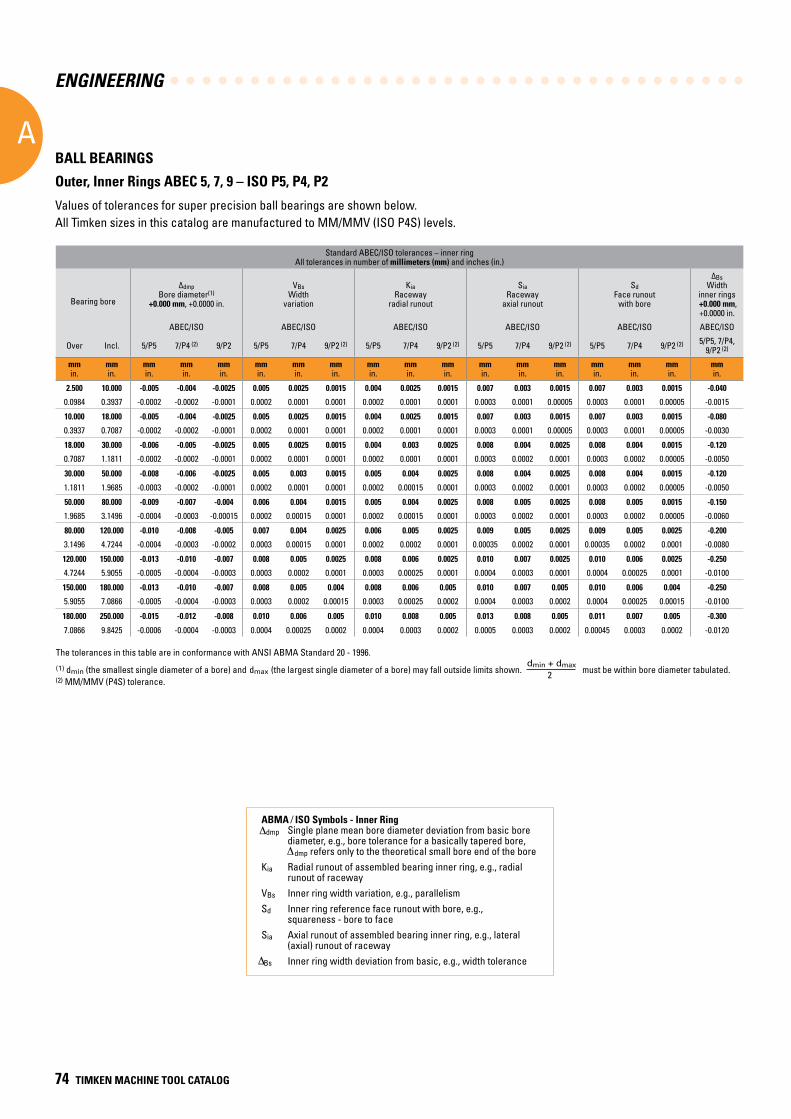
ENGINEERING
A
74 TIMKEN MACHINE TOOL CATALOG
ABMA ⁄ ISO Symbols - Inner Ring dmp Single plane mean bore diameter deviation from basic bore diameter, e.g., bore tolerance for a basically tapered bore, dmp refers only to the theoretical small bore end of the boreKia Radial runout of assembled bearing inner ring, e.g., radial runout of racewayVBs Inner ring width variation, e.g., parallelismSd Inner ring reference face runout with bore, e.g., squareness - bore to faceSia Axial runout of assembled bearing inner ring, e.g., lateral (axial) runout of raceway Bs Inner ring width deviation from basic, e.g., width tolerance
Standard ABEC/ISO tolerances – inner ringAll tolerances in number of millimeters (mm) and inches (in.)
Bearing bore
ΔdmpBore diameter(1)
+0.000 mm, +0.0000 in.
VBsWidth
variation
KiaRaceway
radial runout
SiaRaceway
axial runout
SdFace runout
with bore
ΔBsWidth
inner rings +0.000 mm, +0.0000 in.
ABEC/ISO ABEC/ISO ABEC/ISO ABEC/ISO ABEC/ISO ABEC/ISO
Over Incl. 5/P5 7/P4 (2) 9/P2 5/P5 7/P4 9/P2 (2) 5/P5 7/P4 9/P2 (2) 5/P5 7/P4 9/P2 (2) 5/P5 7/P4 9/P2 (2) 5/P5, 7/P4, 9/P2 (2)
mmin.
mmin.
mmin.
mmin.
mmin.
mmin.
mmin.
mmin.
mmin.
mmin.
mmin.
mmin.
mmin.
mmin.
mmin.
mmin.
mmin.
mmin.
2 .500 10 .000 -0 .005 -0 .004 -0 .0025 0 .005 0 .0025 0 .0015 0 .004 0 .0025 0 .0015 0 .007 0 .003 0 .0015 0 .007 0 .003 0 .0015 -0 .040
0.0984 0.3937 -0.0002 -0.0002 -0.0001 0.0002 0.0001 0.0001 0.0002 0.0001 0.0001 0.0003 0.0001 0.00005 0.0003 0.0001 0.00005 -0.0015
10 .000 18 .000 -0 .005 -0 .004 -0 .0025 0 .005 0 .0025 0 .0015 0 .004 0 .0025 0 .0015 0 .007 0 .003 0 .0015 0 .007 0 .003 0 .0015 -0 .080
0.3937 0.7087 -0.0002 -0.0002 -0.0001 0.0002 0.0001 0.0001 0.0002 0.0001 0.0001 0.0003 0.0001 0.00005 0.0003 0.0001 0.00005 -0.0030
18 .000 30 .000 -0 .006 -0 .005 -0 .0025 0 .005 0 .0025 0 .0015 0 .004 0 .003 0 .0025 0 .008 0 .004 0 .0025 0 .008 0 .004 0 .0015 -0 .120
0.7087 1.1811 -0.0002 -0.0002 -0.0001 0.0002 0.0001 0.0001 0.0002 0.0001 0.0001 0.0003 0.0002 0.0001 0.0003 0.0002 0.00005 -0.0050
30 .000 50 .000 -0 .008 -0 .006 -0 .0025 0 .005 0 .003 0 .0015 0 .005 0 .004 0 .0025 0 .008 0 .004 0 .0025 0 .008 0 .004 0 .0015 -0 .120
1.1811 1.9685 -0.0003 -0.0002 -0.0001 0.0002 0.0001 0.0001 0.0002 0.00015 0.0001 0.0003 0.0002 0.0001 0.0003 0.0002 0.00005 -0.0050
50 .000 80 .000 -0 .009 -0 .007 -0 .004 0 .006 0 .004 0 .0015 0 .005 0 .004 0 .0025 0 .008 0 .005 0 .0025 0 .008 0 .005 0 .0015 -0 .150
1.9685 3.1496 -0.0004 -0.0003 -0.00015 0.0002 0.00015 0.0001 0.0002 0.00015 0.0001 0.0003 0.0002 0.0001 0.0003 0.0002 0.00005 -0.0060
80 .000 120 .000 -0 .010 -0 .008 -0 .005 0 .007 0 .004 0 .0025 0 .006 0 .005 0 .0025 0 .009 0 .005 0 .0025 0 .009 0 .005 0 .0025 -0 .200
3.1496 4.7244 -0.0004 -0.0003 -0.0002 0.0003 0.00015 0.0001 0.0002 0.0002 0.0001 0.00035 0.0002 0.0001 0.00035 0.0002 0.0001 -0.0080
120 .000 150 .000 -0 .013 -0 .010 -0 .007 0 .008 0 .005 0 .0025 0 .008 0 .006 0 .0025 0 .010 0 .007 0 .0025 0 .010 0 .006 0 .0025 -0 .250
4.7244 5.9055 -0.0005 -0.0004 -0.0003 0.0003 0.0002 0.0001 0.0003 0.00025 0.0001 0.0004 0.0003 0.0001 0.0004 0.00025 0.0001 -0.0100
150 .000 180 .000 -0 .013 -0 .010 -0 .007 0 .008 0 .005 0 .004 0 .008 0 .006 0 .005 0 .010 0 .007 0 .005 0 .010 0 .006 0 .004 -0 .250
5.9055 7.0866 -0.0005 -0.0004 -0.0003 0.0003 0.0002 0.00015 0.0003 0.00025 0.0002 0.0004 0.0003 0.0002 0.0004 0.00025 0.00015 -0.0100
180 .000 250 .000 -0 .015 -0 .012 -0 .008 0 .010 0 .006 0 .005 0 .010 0 .008 0 .005 0 .013 0 .008 0 .005 0 .011 0 .007 0 .005 -0 .300
7.0866 9.8425 -0.0006 -0.0004 -0.0003 0.0004 0.00025 0.0002 0.0004 0.0003 0.0002 0.0005 0.0003 0.0002 0.00045 0.0003 0.0002 -0.0120
TOLERANCES – continued
BALL BEARINGS
Outer, Inner Rings ABEC 5, 7, 9 – ISO P5, P4, P2
Values of tolerances for super precision ball bearings are shown below. All Timken sizes in this catalog are manufactured to MM/MMV (ISO P4S) levels.
The tolerances in this table are in conformance with ANSI ABMA Standard 20 - 1996.
(1) dmin (the smallest single diameter of a bore) and dmax (the largest single diameter of a bore) may fall outside limits shown.
dmin + dmax
2 must be within bore diameter tabulated.
(2) MM/MMV (P4S) tolerance.
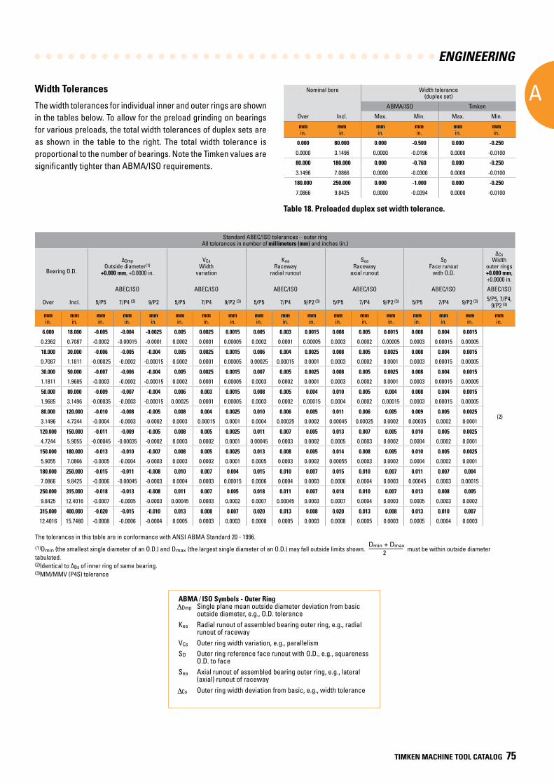
ENGINEERING
A
TIMKEN MACHINE TOOL CATALOG 75
Width Tolerances
The width tolerances for individual inner and outer rings are shown in the tables below. To allow for the preload grinding on bearings for various preloads, the total width tolerances of duplex sets are as shown in the table to the right. The total width tolerance is proportional to the number of bearings. Note the Timken values are significantly tighter than ABMA/ISO requirements.
Nominal bore Width tolerance (duplex set)
ABMA/ISO Timken
Over Incl. Max. Min. Max. Min.
mmin.
mmin.
mmin.
mmin.
mmin.
mmin.
0.000 80.000 0.000 -0.500 0.000 -0.250
0.0000 3.1496 0.0000 -0.0196 0.0000 -0.0100
80.000 180.000 0.000 -0.760 0.000 -0.250
3.1496 7.0866 0.0000 -0.0300 0.0000 -0.0100
180.000 250.000 0.000 -1.000 0.000 -0.250
7.0866 9.8425 0.0000 -0.0394 0.0000 -0.0100
Table 18. Preloaded duplex set width tolerance.
The tolerances in this table are in conformance with ANSI ABMA Standard 20 - 1996.
(1)Dmin (the smallest single diameter of an O.D.) and Dmax (the largest single diameter of an O.D.) may fall outside limits shown.
Dmin + Dmax
2 must be within outside diameter
tabulated.(2)Identical to ΔBs of inner ring of same bearing.(3)MM/MMV (P4S) tolerance
Standard ABEC/ISO tolerances – outer ringAll tolerances in number of millimeters (mm) and inches (in.)
Bearing O.D.
ΔDmpOutside diameter(1)
+0.000 mm, +0.0000 in.
VCsWidth
variation
KeaRaceway
radial runout
SeaRaceway
axial runout
SDFace runout
with O.D.
ΔCsWidth
outer rings+0.000 mm, +0.0000 in.
ABEC/ISO ABEC/ISO ABEC/ISO ABEC/ISO ABEC/ISO ABEC/ISO
Over Incl. 5/P5 7/P4 (3) 9/P2 5/P5 7/P4 9/P2 (3) 5/P5 7/P4 9/P2 (3) 5/P5 7/P4 9/P2 (3) 5/P5 7/P4 9/P2 (3) 5/P5, 7/P4, 9/P2 (3)
mmin.
mmin.
mmin.
mmin.
mmin.
mmin.
mmin.
mmin.
mmin.
mmin.
mmin.
mmin.
mmin.
mmin.
mmin.
mmin.
mmin.
mmin.
6 .000 18 .000 -0 .005 -0 .004 -0 .0025 0 .005 0 .0025 0 .0015 0 .005 0 .003 0 .0015 0 .008 0 .005 0 .0015 0 .008 0 .004 0 .0015
(2)
0.2362 0.7087 -0.0002 -0.00015 -0.0001 0.0002 0.0001 0.00005 0.0002 0.0001 0.00005 0.0003 0.0002 0.00005 0.0003 0.00015 0.00005
18 .000 30 .000 -0 .006 -0 .005 -0 .004 0 .005 0 .0025 0 .0015 0 .006 0 .004 0 .0025 0 .008 0 .005 0 .0025 0 .008 0 .004 0 .0015
0.7087 1.1811 -0.00025 -0.0002 -0.00015 0.0002 0.0001 0.00005 0.00025 0.00015 0.0001 0.0003 0.0002 0.0001 0.0003 0.00015 0.00005
30 .000 50 .000 -0 .007 -0 .006 -0 .004 0 .005 0 .0025 0 .0015 0 .007 0 .005 0 .0025 0 .008 0 .005 0 .0025 0 .008 0 .004 0 .0015
1.1811 1.9685 -0.0003 -0.0002 -0.00015 0.0002 0.0001 0.00005 0.0003 0.0002 0.0001 0.0003 0.0002 0.0001 0.0003 0.00015 0.00005
50 .000 80 .000 -0 .009 -0 .007 -0 .004 0 .006 0 .003 0 .0015 0 .008 0 .005 0 .004 0 .010 0 .005 0 .004 0 .008 0 .004 0 .0015
1.9685 3.1496 -0.00035 -0.0003 -0.00015 0.00025 0.0001 0.00005 0.0003 0.0002 0.00015 0.0004 0.0002 0.00015 0.0003 0.00015 0.00005
80 .000 120 .000 -0 .010 -0 .008 -0 .005 0 .008 0 .004 0 .0025 0 .010 0 .006 0 .005 0 .011 0 .006 0 .005 0 .009 0 .005 0 .0025
3.1496 4.7244 -0.0004 -0.0003 -0.0002 0.0003 0.00015 0.0001 0.0004 0.00025 0.0002 0.00045 0.00025 0.0002 0.00035 0.0002 0.0001
120 .000 150 .000 -0 .011 -0 .009 -0 .005 0 .008 0 .005 0 .0025 0 .011 0 .007 0 .005 0 .013 0 .007 0 .005 0 .010 0 .005 0 .0025
4.7244 5.9055 -0.00045 -0.00035 -0.0002 0.0003 0.0002 0.0001 0.00045 0.0003 0.0002 0.0005 0.0003 0.0002 0.0004 0.0002 0.0001
150 .000 180 .000 -0 .013 -0 .010 -0 .007 0 .008 0 .005 0 .0025 0 .013 0 .008 0 .005 0 .014 0 .008 0 .005 0 .010 0 .005 0 .0025
5.9055 7.0866 -0.0005 -0.0004 -0.0003 0.0003 0.0002 0.0001 0.0005 0.0003 0.0002 0.00055 0.0003 0.0002 0.0004 0.0002 0.0001
180 .000 250 .000 -0 .015 -0 .011 -0 .008 0 .010 0 .007 0 .004 0 .015 0 .010 0 .007 0 .015 0 .010 0 .007 0 .011 0 .007 0 .004
7.0866 9.8425 -0.0006 -0.00045 -0.0003 0.0004 0.0003 0.00015 0.0006 0.0004 0.0003 0.0006 0.0004 0.0003 0.00045 0.0003 0.00015
250 .000 315 .000 -0 .018 -0 .013 -0 .008 0 .011 0 .007 0 .005 0 .018 0 .011 0 .007 0 .018 0 .010 0 .007 0 .013 0 .008 0 .005
9.8425 12.4016 -0.0007 -0.0005 -0.0003 0.00045 0.0003 0.0002 0.0007 0.00045 0.0003 0.0007 0.0004 0.0003 0.0005 0.0003 0.0002
315 .000 400 .000 -0 .020 -0 .015 -0 .010 0 .013 0 .008 0 .007 0 .020 0 .013 0 .008 0 .020 0 .013 0 .008 0 .013 0 .010 0 .007
12.4016 15.7480 -0.0008 -0.0006 -0.0004 0.0005 0.0003 0.0003 0.0008 0.0005 0.0003 0.0008 0.0005 0.0003 0.0005 0.0004 0.0003
ABMA ⁄ ISO Symbols - Outer Ring Dmp Single plane mean outside diameter deviation from basic outside diameter, e.g., O.D. toleranceKea Radial runout of assembled bearing outer ring, e.g., radial runout of racewayVCs Outer ring width variation, e.g., parallelismSD Outer ring reference face runout with O.D., e.g., squareness O.D. to faceSea Axial runout of assembled bearing outer ring, e.g., lateral (axial) runout of raceway Cs Outer ring width deviation from basic, e.g., width tolerance
ENGINEERING
A
76 TIMKEN MACHINE TOOL CATALOG
FITTING PRACTICES
GENERAL GUIDELINES FOR TAPERED ROLLER BEARINGS
The design of a tapered roller bearing permits the setting to be achieved during installation (or during running when using a Hydra-Rib), irrespective of the inner and outer ring fits on shaft and housing. This allows the use of the widest possible machining tolerances for shaft and housing and the use of the best possible fits for the inner and outer rings to match the duty of the bearing.
The fitting practice will depend upon the following parameters:
• Precision class of the bearing.
• Type of layout.
• Type and direction of loads.
• Running conditions (vibrations, high speeds).
• Shaft and housing sections and materials.
• Mounting and setting conditions.
Certain table fits may not be adequate for light shaft and housing sections, shafts other than steel, nonferrous housings, critical operation conditions such as high speed, unusual thermal or loading conditions or a combination thereof. Also assembly procedures and the means and ease of obtaining the bearing setting may require special fits. In these cases, experience should be used as a guideline or your Timken representative should be consulted for review and suggestions.
Precision class bearings should be mounted on shafts and in housings which are similarly finished to at least the same precision limits as the bearing bore and O.D. High-quality surface finishes should also be provided.
In the machine tool industry, where almost 100 percent of cases are rotating shaft applications, the general rule is to tight-fit both the inner and outer rings for simple layouts to eliminate any undesirable radial clearance.Tapered roller bearing envelope tolerances can be adjusted to the needs of a specific application.
NON-FERROUS HOUSINGS
Care should be taken when pressing cups into aluminum or magnesium housings to avoid metal pick up. This may result in unsatisfactory fits, backing, and alignment from debris trapped between the cup and backing shoulder. Preferably, the cup should be frozen or the housing heated, or both, during assembly. Also, a special lubricant may be used to ease assembly. In some cases, cups are mounted in steel inserts which are attached to the aluminum or magnesium housings. Table fits may then be used. Where the cup is fitted directly into an aluminum housing, it is suggested that a minimum tight fit of 1.0 μm per mm (0.0010 in. per in.) of cup outside diameter be used. For a magnesium housing, a minimum tight fit of 1.5 μm per mm (0.0015 in. per in.) of cup outside diameter is suggested.
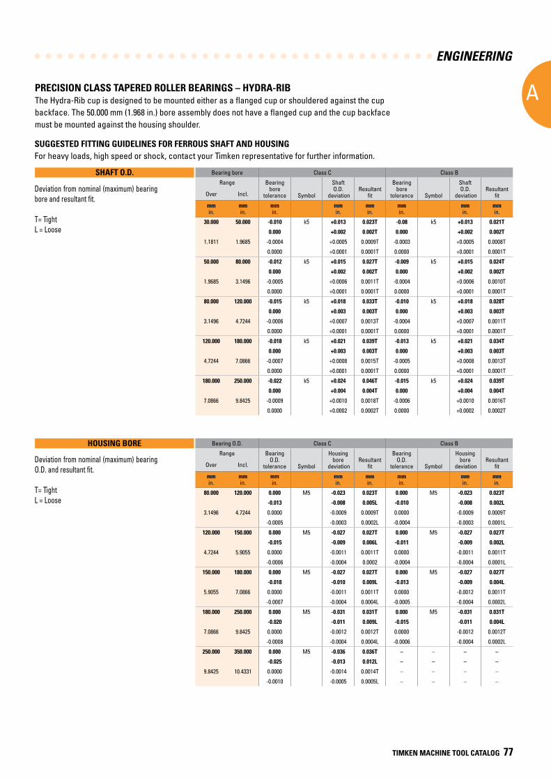
ENGINEERING
A
TIMKEN MACHINE TOOL CATALOG 77
SHAFT O.D.
SUGGESTED FITTING GUIDELINES FOR FERROUS SHAFT AND HOUSINGFor heavy loads, high speed or shock, contact your Timken representative for further information.
PRECISION CLASS TAPERED ROLLER BEARINGS – HYDRA-RIB The Hydra-Rib cup is designed to be mounted either as a flanged cup or shouldered against the cup backface. The 50.000 mm (1.968 in.) bore assembly does not have a flanged cup and the cup backface must be mounted against the housing shoulder.
Bearing bore Class C Class B
Range Bearingbore
tolerance Symbol
Shaft O.D.
deviationResultant
fit
Bearingbore
tolerance Symbol
Shaft O.D.
deviationResultant
fitOver Incl.
mmin.
mmin.
mmin.
mmin.
mmin.
mmin.
mmin.
mmin.
30.000 50.000 -0.010 k5 +0.013 0.023T -0.08 k5 +0.013 0.021T
0.000 +0.002 0.002T 0.000 +0.002 0.002T
1.1811 1.9685 -0.0004 +0.0005 0.0009T -0.0003 +0.0005 0.0008T
0.0000 +0.0001 0.0001T 0.0000 +0.0001 0.0001T
50.000 80.000 -0.012 k5 +0.015 0.027T -0.009 k5 +0.015 0.024T
0.000 +0.002 0.002T 0.000 +0.002 0.002T
1.9685 3.1496 -0.0005 +0.0006 0.0011T -0.0004 +0.0006 0.0010T
0.0000 +0.0001 0.0001T 0.0000 +0.0001 0.0001T
80.000 120.000 -0.015 k5 +0.018 0.033T -0.010 k5 +0.018 0.028T
0.000 +0.003 0.003T 0.000 +0.003 0.003T
3.1496 4.7244 -0.0006 +0.0007 0.0013T -0.0004 +0.0007 0.0011T
0.0000 +0.0001 0.0001T 0.0000 +0.0001 0.0001T
120.000 180.000 -0.018 k5 +0.021 0.039T -0.013 k5 +0.021 0.034T
0.000 +0.003 0.003T 0.000 +0.003 0.003T
4.7244 7.0866 -0.0007 +0.0008 0.0015T -0.0005 +0.0008 0.0013T
0.0000 +0.0001 0.0001T 0.0000 +0.0001 0.0001T
180.000 250.000 -0.022 k5 +0.024 0.046T -0.015 k5 +0.024 0.039T
0.000 +0.004 0.004T 0.000 +0.004 0.004T
7.0866 9.8425 -0.0009 +0.0010 0.0018T -0.0006 +0.0010 0.0016T
0.0000 +0.0002 0.0002T 0.0000 +0.0002 0.0002T
HOUSING BORE Bearing O.D. Class C Class B
Range BearingO.D.
tolerance Symbol
Housing bore
deviationResultant
fit
BearingO.D.
tolerance Symbol
Housing bore
deviationResultant
fitOver Incl.
mmin.
mmin.
mmin.
mmin.
mmin.
mmin.
mmin.
mmin.
80.000 120.000 0.000 M5 -0.023 0.023T 0.000 M5 -0.023 0.023T
-0.013 -0.008 0.005L -0.010 -0.008 0.002L
3.1496 4.7244 0.0000 -0.0009 0.0009T 0.0000 -0.0009 0.0009T
-0.0005 -0.0003 0.0002L -0.0004 -0.0003 0.0001L
120.000 150.000 0.000 M5 -0.027 0.027T 0.000 M5 -0.027 0.027T
-0.015 -0.009 0.006L -0.011 -0.009 0.002L
4.7244 5.9055 0.0000 -0.0011 0.0011T 0.0000 -0.0011 0.0011T
-0.0006 -0.0004 0.0002 -0.0004 -0.0004 0.0001L
150.000 180.000 0.000 M5 -0.027 0.027T 0.000 M5 -0.027 0.027T
-0.018 -0.010 0.009L -0.013 -0.009 0.004L
5.9055 7.0866 0.0000 -0.0011 0.0011T 0.0000 -0.0012 0.0011T
-0.0007 -0.0004 0.0004L -0.0005 -0.0004 0.0002L
180.000 250.000 0.000 M5 -0.031 0.031T 0.000 M5 -0.031 0.031T
-0.020 -0.011 0.009L -0.015 -0.011 0.004L
7.0866 9.8425 0.0000 -0.0012 0.0012T 0.0000 -0.0012 0.0012T
-0.0008 -0.0004 0.0004L -0.0006 -0.0004 0.0002L
250.000 350.000 0.000 M5 -0.036 0.036T – – – –
-0.025 -0.013 0.012L – – – –
9.8425 10.4331 0.0000 -0.0014 0.0014T – – – –
-0.0010 -0.0005 0.0005L – – – –
Deviation from nominal (maximum) bearing O.D. and resultant fit.
T= TightL = Loose
Deviation from nominal (maximum) bearing bore and resultant fit.
T= TightL = Loose
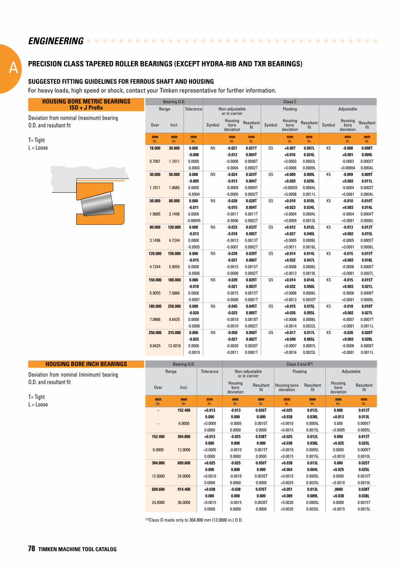
ENGINEERING
A
78 TIMKEN MACHINE TOOL CATALOG
PRECISION CLASS TAPERED ROLLER BEARINGS (EXCEPT HYDRA-RIB AND TXR BEARINGS)
(1)Class O made only to 304.800 mm (12.0000 in.) O.D.
Deviation from nominal (minimum) bearing O.D. and resultant fit
T= TightL = Loose
Deviation from nominal (maximum) bearing O.D. and resultant fit
T= TightL = Loose
HOUSING BORE METRIC BEARINGS ISO + J Prefix
Bearing O.D. Class 3 and 0(1)
Range Tolerance Non-adjustableor in carrier
Floating Adjustable
Over Incl.Housing
boredeviation
Resultant fit
Housing bore deviation
Resultantfit
Housing bore
deviationResultant
fit
mmin.
mmin.
mmin.
mmin.
mmin.
mmin.
mmin.
mmin.
mmin.
– 152.400 +0.013 -0.013 0.026T +0.025 0.012L 0.000 0.013T0.000 0.000 0.000 +0.038 0.038L +0.013 0.013L
– 6.0000 +0.0005 -0.0005 0.0010T +0.0010 0.0005L 0.000 0.0005T0.0000 0.0000 0.0000 +0.0015 0.0015L +0.0005 0.0005L
152.400 304.800 +0.013 -0.025 0.038T +0.025 0.012L 0.000 0.013T0.000 0.000 0.000 +0.038 0.038L +0.025 0.025L
6.0000 12.0000 +0.0005 -0.0010 0.0015T +0.0010 0.0005L 0.0000 0.0005T0.0000 0.0000 0.0000 +0.0015 0.0015L +0.0010 0.0010L
304.800 609.600 +0.025 -0.025 0.050T +0.038 0.013L 0.000 0.025T0.000 0.000 0.000 +0.064 0.064L +0.025 0.025L
12.0000 24.0000 +0.0010 -0.0010 0.0020T +0.0015 0.0005L 0.0000 0.0010T0.0000 0.0000 0.0000 +0.0025 0.0025L +0.0010 0.0010L
609.600 914.400 +0.038 -0.038 0.076T +0.051 0.013L ,0000 0.038T0.000 0.000 0.000 +0.089 0.089L +0.038 0.038L
24.0000 36.0000 +0.0015 -0.0015 0.0030T +0.0020 0.0005L 0.0000 0.0015T0.0000 0.0000 0.0000 +0.0035 0.0035L +0.0015 0.0015L
HOUSING BORE INCH BEARINGS
SUGGESTED FITTING GUIDELINES FOR FERROUS SHAFT AND HOUSINGFor heavy loads, high speed or shock, contact your Timken representative for further information.
Bearing O.D. Class C
Range Tolerance Non-adjustable or in carrier
Floating Adjustable
Over Incl. SymbolHousing
boredeviation
Resultant fit Symbol
Housing bore
deviationResultant
fit SymbolHousing
boredeviation
Resultantfit
mmin.
mmin.
mmin.
mmin.
mmin. mm
in.mmin.
mmin.
mmin.
18.000 30.000 0.000 N5 -0.021 0.021T G5 +0.007 0.007L K5 -0.008 0.008T -0.008 -0.012 0.004T +0.016 0.024L +0.001 0.009L
0.7087 1.1811 0.0000 -0.0008 0.0008T +0.0003 0.0003L -0.0003 0.0003T-0.0003 -0.0004 0.0002T +0.0006 0.0009L +0.00004 0.0004L
30.000 50.000 0.000 N5 -0.024 0.024T G5 +0.009 0.009L K5 -0.009 0.009T -0.009 -0.013 0.004T +0.020 0.029L +0.002 0.011L
1.1811 1.9685 0.0000 -0.0009 0.0009T +0.00035 0.0004L -0.0004 0.0003T-0.0004 -0.0005 0.0002T +0.0008 0.0011L +0.0001 0.0004L
50.000 80.000 0.000 N5 -0.028 0.028T G5 +0.010 0.010L K5 -0.010 0.010T -0.011 -0.015 0.004T +0.023 0.034L +0.003 0.014L
1.9685 3.1496 0.0000 -0.0011 0.0011T +0.0004 0.0004L -0.0004 0.0004T-0.00045 -0.0006 0.0002T +0.0009 0.0013L +0.0001 0.0006L
80.000 120.000 0.000 N5 -0.033 0.033T G5 +0.012 0.012L K5 -0.013 0.013T -0.013 -0.018 0.005T +0.027 0.040L +0.002 0.015L
3.1496 4.7244 0.0000 -0.0013 0.0013T +0.0005 0.0008L -0.0005 0.0005T-0.0005 -0.0007 0.0002T +0.0011 0.0016L +0.0001 0.0006L
120.000 150.000 0.000 N5 -0.039 0.039T G5 +0.014 0.014L K5 -0.015 0.015T -0.015 -0.021 0.006T +0.032 0.047L +0.003 0.018L
4.7244 5.9055 0.0000 -0.0015 0.0015T +0.0006 0.0006L -0.0006 0.0006T-0.0006 -0.0008 0.0002T +0.0013 0.0019L +0.0001 0.0007L
150.000 180.000 0.000 N5 -0.039 0.039T G5 +0.014 0.014L K5 -0.015 0.015T -0.018 -0.021 0.003T +0.032 0.050L +0.003 0.021L
5.9055 7.0866 0.0000 -0.0015 0.0015T +0.0006 0.0006L -0.0006 0.0006T-0.0007 -0.0008 0.0001T +0.0013 0.0020T +0.0001 0.0008L
180.000 250.000 0.000 N5 -0.045 0.045T G5 +0.015 0.015L K5 -0.018 0.018T -0.020 -0.025 0.005T +0.035 0.055L +0.002 0.027L
7.0866 9.8425 0.0000 -0.0018 0.0018T +0.0006 0.0006L -0.0007 0.0007T-0.0008 -0.0010 0.0002T +0.0014 0.0022L +0.0001 0.0011L
250.000 315.000 0.000 N5 -0.050 0.050T G5 +0.017 0.017L K5 -0.020 0.020T -0.025 -0.027 0.002T +0.040 0.065L +0.003 0.028L
9.8425 12.4016 0.0000 -0.0020 0.0020T +0.0007 0.0007L -0.0008 0.0008T-0.0010 -0.0011 0.0001T +0.0016 0.0023L +0.0001 0.0011L
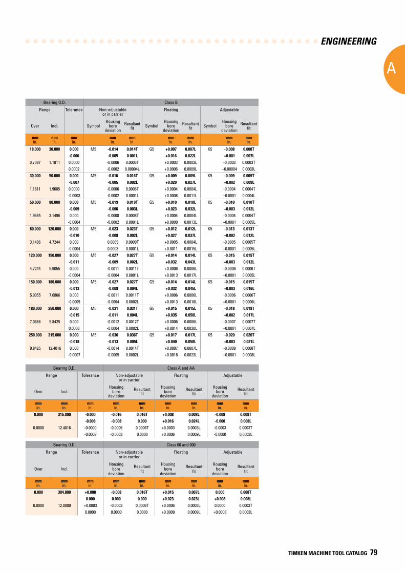
ENGINEERING
A
TIMKEN MACHINE TOOL CATALOG 79
Bearing O.D. Class A and AA
Range Tolerance Non-adjustableor in carrier
Floating Adjustable
Over Incl.Housing
boredeviation
Resultant fit
Housing bore
deviationResultant
fitHousing
boredeviation
Resultantfit
mmin.
mmin.
mmin.
mmin.
mmin.
mmin.
mmin.
mmin.
mmin.
0.000 315.000 -0.000 -0.016 0.016T +0.008 0.008L -0.008 0.008T-0.008 -0.008 0.000 +0.016 0.024L -0.000 0.008L
0.0000 12.4016 -0.0000 -0.0006 0.0006T +0.0003 0.0003L -0.0003 0.0003T-0.0003 -0.0003 0.0000 +0.0006 0.0009L -0.0000 0.0003L
Bearing O.D. Class 00 and 000
Range Tolerance Non-adjustableor in carrier
Floating Adjustable
Over Incl.Housing
boredeviation
Resultant fit
Housing bore
deviation
Resultantfit
Housing bore
deviation
Resultantfit
mmin.
mmin.
mmin.
mmin.
mmin.
mmin.
mmin.
mmin.
mmin.
0.000 304.800 +0.008 -0.008 0.016T +0.015 0.007L 0.000 0.008T0.000 0.000 0.000 +0.023 0.023L +0.008 0.008L
0.0000 12.0000 +0.0003 -0.0003 0.0006T +0.0006 0.0003L 0.0000 0.0003T0.0000 0.0000 0.0000 +0.0009 0.0009L +0.0003 0.0003L
Bearing O.D. Class B
Range Tolerance Non-adjustable or in carrier
Floating Adjustable
Over Incl. SymbolHousing
boredeviation
Resultant fit Symbol
Housing bore
deviationResultant
fit SymbolHousing
boredeviation
Resultantfit
mmin.
mmin.
mmin.
mmin.
mmin. mm
in.mmin.
mmin.
mmin.
18.000 30.000 0.000 M5 -0.014 0.014T G5 +0.007 0.007L K5 -0.008 0.008T -0.006 -0.005 0.001L +0.016 0.022L +0.001 0.007L
0.7087 1.1811 0.0000 -0.0006 0.0006T +0.0003 0.0003L -0.0003 0.0003T0.0002 -0.0002 0.00004L +0.0006 0.0009L +0.00004 0.0003L
30.000 50.000 0.000 M5 -0.016 0.016T G5 +0.009 0.009L K5 -0.009 0.009T -0.007 -0.005 0.002L +0.020 0.027L +0.002 0.009L
1.1811 1.9685 0.0000 -0.0006 0.0006T +0.0004 0.0004L -0.0004 0.0004T-0.0003 -0.0002 0.0001L +0.0008 0.0011L +0.0001 0.0004L
50.000 80.000 0.000 M5 -0.019 0.019T G5 +0.010 0.010L K5 -0.010 0.010T -0.009 -0.006 0.003L +0.023 0.032L +0.003 0.012L
1.9685 3.1496 0.000 -0.0008 0.0008T +0.0004 0.0004L -0.0004 0.0004T-0.0004 -0.0002 0.0001L +0.0009 0.0013L +0.0001 0.0005L
80.000 120.000 0.000 M5 -0.023 0.023T G5 +0.012 0.012L K5 -0.013 0.013T -0.010 -0.008 0.002L +0.027 0.037L +0.002 0.012L
3.1496 4.7244 0.000 0.0009 0.0009T +0.0005 0.0004L -0.0005 0.0005T-0.0004 0.0003 0.0001L +0.0011 0.0015L +0.0001 0.0005L
120.000 150.000 0.000 M5 -0.027 0.027T G5 +0.014 0.014L K5 -0.015 0.015T -0.011 -0.009 0.002L +0.032 0.043L +0.003 0.012L
4.7244 5.9055 0.000 -0.0011 0.0011T +0.0006 0.0006L -0.0006 0.0006T-0.0004 -0.0004 0.0001L +0.0013 0.0017L +0.0001 0.0005L
150.000 180.000 0.000 M5 -0.027 0.027T G5 +0.014 0.014L K5 -0.015 0.015T -0.013 -0.009 0.004L +0.032 0.045L +0.003 0.016L
5.9055 7.0866 0.000 -0.0011 0.0011T +0.0006 0.0006L -0.0006 0.0006T-0.0005 -0.0004 0.0002L +0.0013 0.0018L +0.0001 0.0006L
180.000 250.000 0.000 M5 -0.031 0.031T G5 +0.015 0.015L K5 -0.018 0.018T -0.015 -0.011 0.004L +0.035 0.050L +0.002 0.017L
7.0866 9.8425 0.000 -0.0012 0.0012T +0.0006 0.0006L -0.0007 0.0007T0.0006 -0.0004 0.0002L +0.0014 0.0020L +0.0001 0.0007L
250.000 315.000 0.000 M5 -0.036 0.036T G5 +0.017 0.017L K5 -0.020 0.020T -0.018 -0.013 0.005L +0.040 0.058L +0.003 0.021L
9.8425 12.4016 0.000 -0.0014 0.0014T +0.0007 0.0007L -0.0008 0.0008T-0.0007 -0.0005 0.0002L +0.0016 0.0023L +0.0001 0.0008L
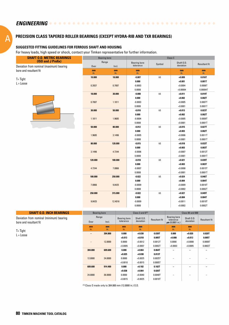
ENGINEERING
A
80 TIMKEN MACHINE TOOL CATALOG
Bearing bore Class 3 and 0(1) Class 00 and 000
Range Bearing bore tolerance
Shaft O.D.deviation Resultant fit
Bearing bore tolerance
μm (0.0001 in.)
Shaft O.D.deviation Resultant fit
Over Incl.
mmin.
mmin.
mmin.
mmin.
mmin.
mmin.
– 304.800 0.000 +0.030 0.030T 0.000 +0.020 0.020T
+0.013 +0.018 0.005T +0.008 +0.013 0.005T
– 12.0000 0.0000 +0.0012 0.0012T 0.0000 +0.0008 0.0008T
+0.0005 +0.0007 0.0002T +0.0003 +0.0005 0.0002T
304.800 609.600 0.000 +0.064 0.064T – – –
+0.025 +0.038 0.013T
12.0000 24.0000 0.0000 +0.0025 0.0025T – – –
+0.0010 +0.0015 0.0005T
609.600 914.400 0.000 +0.102 0.102T – – –
+0.038 +0.064 0.026T
24.0000 36.0000 0.0000 +0.0040 0.0040T – – –
+0.0015 +0.0025 0.0010T
(1) Class O made only to 304.800 mm (12.0000 in.) O.D.
Deviation from nominal (minimum) bearing bore and resultant fit
T= TightL = Loose
Bearing bore Class C
Range Bearing bore tolerance Symbol Shaft O.D.
deviation Resultant fitOver Incl.
mmin.
mmin.
mmin.
mmin.
mmin.
10.000 18.000 -0.007 k5 +0.009 0.016T
0.000 +0.001 0.001T
0.3937 0.7087 -0.0003 +0.0004 0.0006T
0.0000 +0.00004 0.00004T
18.000 30.000 -0.008 k5 +0.011 0.019T
0.000 +0.002 0.002T
0.7087 1.1811 -0.0003 +0.0005 0.0007T
0.0000 +0.0001 0.0001T
30.000 50.000 -0.010 k5 +0.013 0.023T
0.000 +0.002 0.002T
1.1811 1.9685 -0.0004 +0.0005 0.0009T
0.0000 +0.0001 0.0001T
50.000 80.000 -0.012 k5 +0.015 0.027T
0.000 +0.003 0.002T
1.9685 3.1496 -0.0005 +0.0006 0.0011T
0.0000 +0.0001 0.0001T
80.000 120.000 -0.015 k5 +0.018 0.033T
0.000 +0.003 0.003T
3.1496 4.7244 -0.0006 +0.0007 0.0013T
0.0000 +0.0001 0.0001T
120.000 180.000 -0.018 k5 +0.021 0.039T
0.000 +0.003 0.003T
4.7244 7.0866 -0.0007 +0.0008 0.0015T
0.0000 +0.0001 0.0001T
180.000 250.000 -0.022 k5 +0.024 0.046T
0.000 +0.004 0.004T
7.0866 9.8425 -0.0009 +0.0009 0.0018T
0.0000 +0.0002 0.0002T
250.000 315.000 -0.022 k5 +0.027 0.049T
0.000 +0.004 0.004T
9.8425 12.4016 -0.0009 +0.0011 0.0019T
0.0000 +0.0002 0.0002T
Deviation from nominal (maximum) bearing bore and resultant fit
T= TightL = Loose
SHAFT O.D. METRIC BEARINGS (ISO and J Prefix)
SHAFT O.D. INCH BEARINGS
SUGGESTED FITTING GUIDELINES FOR FERROUS SHAFT AND HOUSINGFor heavy loads, high speed or shock, contact your Timken representative for further information.
PRECISION CLASS TAPERED ROLLER BEARINGS (EXCEPT HYDRA-RIB AND TXR BEARINGS)
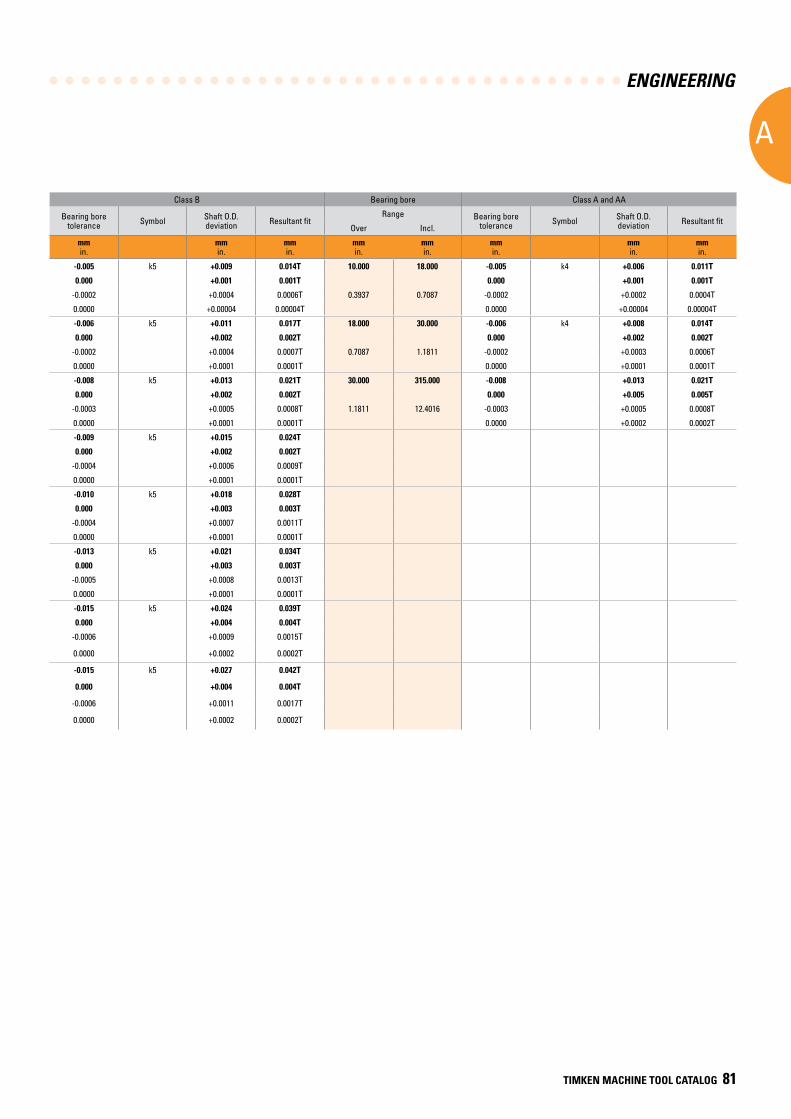
ENGINEERING
A
TIMKEN MACHINE TOOL CATALOG 81
Class B Bearing bore Class A and AA
Bearing bore tolerance Symbol Shaft O.D.
deviation Resultant fitRange Bearing bore
tolerance Symbol Shaft O.D.deviation Resultant fit
Over Incl.
mmin.
mmin.
mmin.
mmin.
mmin.
mmin.
mmin.
mmin.
-0.005 k5 +0.009 0.014T 10.000 18.000 -0.005 k4 +0.006 0.011T
0.000 +0.001 0.001T 0.000 +0.001 0.001T
-0.0002 +0.0004 0.0006T 0.3937 0.7087 -0.0002 +0.0002 0.0004T
0.0000 +0.00004 0.00004T 0.0000 +0.00004 0.00004T
-0.006 k5 +0.011 0.017T 18.000 30.000 -0.006 k4 +0.008 0.014T
0.000 +0.002 0.002T 0.000 +0.002 0.002T
-0.0002 +0.0004 0.0007T 0.7087 1.1811 -0.0002 +0.0003 0.0006T
0.0000 +0.0001 0.0001T 0.0000 +0.0001 0.0001T
-0.008 k5 +0.013 0.021T 30.000 315.000 -0.008 +0.013 0.021T
0.000 +0.002 0.002T 0.000 +0.005 0.005T
-0.0003 +0.0005 0.0008T 1.1811 12.4016 -0.0003 +0.0005 0.0008T
0.0000 +0.0001 0.0001T 0.0000 +0.0002 0.0002T
-0.009 k5 +0.015 0.024T
0.000 +0.002 0.002T
-0.0004 +0.0006 0.0009T
0.0000 +0.0001 0.0001T
-0.010 k5 +0.018 0.028T
0.000 +0.003 0.003T
-0.0004 +0.0007 0.0011T
0.0000 +0.0001 0.0001T
-0.013 k5 +0.021 0.034T
0.000 +0.003 0.003T
-0.0005 +0.0008 0.0013T
0.0000 +0.0001 0.0001T
-0.015 k5 +0.024 0.039T
0.000 +0.004 0.004T
-0.0006 +0.0009 0.0015T
0.0000 +0.0002 0.0002T
-0.015 k5 +0.027 0.042T
0.000 +0.004 0.004T
-0.0006 +0.0011 0.0017T
0.0000 +0.0002 0.0002T
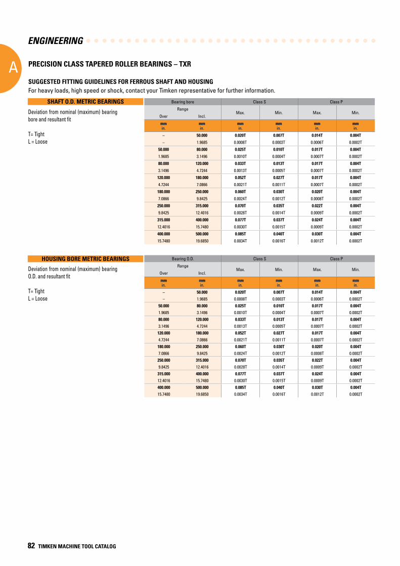
ENGINEERING
A
82 TIMKEN MACHINE TOOL CATALOG
SUGGESTED FITTING GUIDELINES FOR FERROUS SHAFT AND HOUSINGFor heavy loads, high speed or shock, contact your Timken representative for further information.
PRECISION CLASS TAPERED ROLLER BEARINGS – TXR
Bearing bore Class S Class P
RangeMax. Min. Max. Min.
Over Incl.
mmin.
mmin.
mmin.
mmin.
mmin.
mmin.
– 50.000 0.020T 0.007T 0.014T 0.004T
– 1.9685 0.0008T 0.0003T 0.0006T 0.0002T
50.000 80.000 0.025T 0.010T 0.017T 0.004T
1.9685 3.1496 0.0010T 0.0004T 0.0007T 0.0002T
80.000 120.000 0.033T 0.013T 0.017T 0.004T
3.1496 4.7244 0.0013T 0.0005T 0.0007T 0.0002T
120.000 180.000 0.052T 0.027T 0.017T 0.004T
4.7244 7.0866 0.0021T 0.0011T 0.0007T 0.0002T
180.000 250.000 0.060T 0.030T 0.020T 0.004T
7.0866 9.8425 0.0024T 0.0012T 0.0008T 0.0002T
250.000 315.000 0.070T 0.035T 0.022T 0.004T
9.8425 12.4016 0.0028T 0.0014T 0.0009T 0.0002T
315.000 400.000 0.077T 0.037T 0.024T 0.004T
12.4016 15.7480 0.0030T 0.0015T 0.0009T 0.0002T
400.000 500.000 0.085T 0.040T 0.030T 0.004T
15.7480 19.6850 0.0034T 0.0016T 0.0012T 0.0002T
Bearing O.D. Class S Class P
RangeMax. Min. Max. Min.
Over Incl.
mmin.
mmin.
mmin.
mmin.
mmin.
mmin.
– 50.000 0.020T 0.007T 0.014T 0.004T
– 1.9685 0.0008T 0.0003T 0.0006T 0.0002T
50.000 80.000 0.025T 0.010T 0.017T 0.004T
1.9685 3.1496 0.0010T 0.0004T 0.0007T 0.0002T
80.000 120.000 0.033T 0.013T 0.017T 0.004T
3.1496 4.7244 0.0013T 0.0005T 0.0007T 0.0002T
120.000 180.000 0.052T 0.027T 0.017T 0.004T
4.7244 7.0866 0.0021T 0.0011T 0.0007T 0.0002T
180.000 250.000 0.060T 0.030T 0.020T 0.004T
7.0866 9.8425 0.0024T 0.0012T 0.0008T 0.0002T
250.000 315.000 0.070T 0.035T 0.022T 0.004T
9.8425 12.4016 0.0028T 0.0014T 0.0009T 0.0002T
315.000 400.000 0.077T 0.037T 0.024T 0.004T
12.4016 15.7480 0.0030T 0.0015T 0.0009T 0.0002T
400.000 500.000 0.085T 0.040T 0.030T 0.004T
15.7480 19.6850 0.0034T 0.0016T 0.0012T 0.0002T
SHAFT O.D. METRIC BEARINGS
HOUSING BORE METRIC BEARINGS
Deviation from nominal (maximum) bearing O.D. and resultant fit
T= TightL = Loose
Deviation from nominal (maximum) bearing bore and resultant fit
T= TightL = Loose
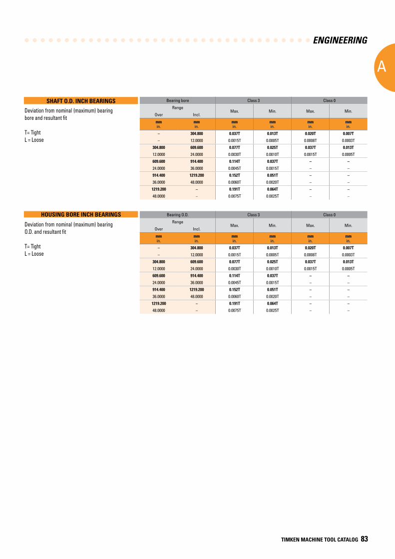
ENGINEERING
A
TIMKEN MACHINE TOOL CATALOG 83
Bearing bore Class 3 Class 0
RangeMax. Min. Max. Min.
Over Incl.
mmin.
mmin.
mmin.
mmin.
mmin.
mmin.
– 304.800 0.037T 0.013T 0.020T 0.007T
– 12.0000 0.0015T 0.0005T 0.0008T 0.0003T
304.800 609.600 0.077T 0.025T 0.037T 0.013T
12.0000 24.0000 0.0030T 0.0010T 0.0015T 0.0005T
609.600 914.400 0.114T 0.037T – –
24.0000 36.0000 0.0045T 0.0015T – –
914.400 1219.200 0.152T 0.051T – –
36.0000 48.0000 0.0060T 0.0020T – –
1219.200 – 0.191T 0.064T – –
48.0000 – 0.0075T 0.0025T – –
Bearing O.D. Class 3 Class 0
RangeMax. Min. Max. Min.
Over Incl.
mmin.
mmin.
mmin.
mmin.
mmin.
mmin.
– 304.800 0.037T 0.013T 0.020T 0.007T
– 12.0000 0.0015T 0.0005T 0.0008T 0.0003T
304.800 609.600 0.077T 0.025T 0.037T 0.013T
12.0000 24.0000 0.0030T 0.0010T 0.0015T 0.0005T
609.600 914.400 0.114T 0.037T – –
24.0000 36.0000 0.0045T 0.0015T – –
914.400 1219.200 0.152T 0.051T – –
36.0000 48.0000 0.0060T 0.0020T – –
1219.200 – 0.191T 0.064T – –
48.0000 – 0.0075T 0.0025T – –
SHAFT O.D. INCH BEARINGS
HOUSING BORE INCH BEARINGS
Deviation from nominal (maximum) bearing O.D. and resultant fit
T= TightL = Loose
Deviation from nominal (maximum) bearing bore and resultant fit
T= TightL = Loose
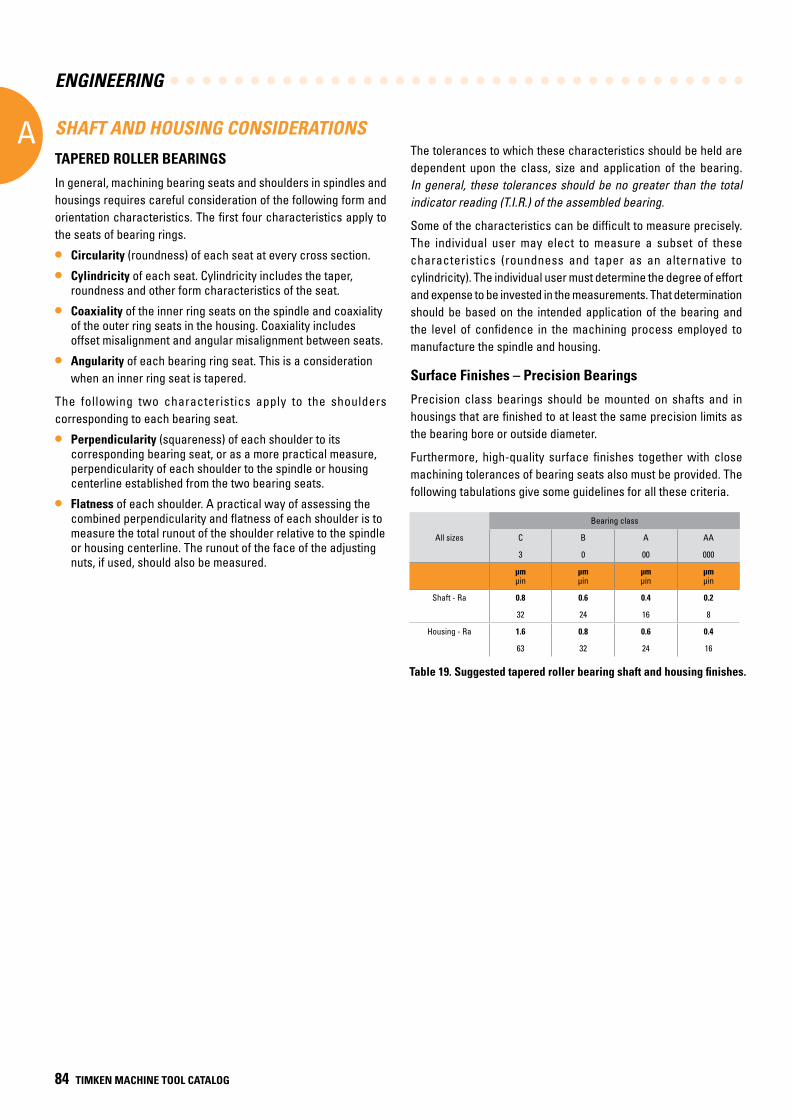
ENGINEERING
A
84 TIMKEN MACHINE TOOL CATALOG
SHAFT AND HOUSING CONSIDERATIONS
TAPERED ROLLER BEARINGS
In general, machining bearing seats and shoulders in spindles and housings requires careful consideration of the following form and orientation characteristics. The first four characteristics apply to the seats of bearing rings.
• Circularity (roundness) of each seat at every cross section.
• Cylindricity of each seat. Cylindricity includes the taper, roundness and other form characteristics of the seat.
• Coaxiality of the inner ring seats on the spindle and coaxiality of the outer ring seats in the housing. Coaxiality includes offset misalignment and angular misalignment between seats.
• Angularity of each bearing ring seat. This is a consideration when an inner ring seat is tapered.
The following two characteristics apply to the shoulders corresponding to each bearing seat.
• Perpendicularity (squareness) of each shoulder to its corresponding bearing seat, or as a more practical measure, perpendicularity of each shoulder to the spindle or housing centerline established from the two bearing seats.
• Flatness of each shoulder. A practical way of assessing the combined perpendicularity and flatness of each shoulder is to measure the total runout of the shoulder relative to the spindle or housing centerline. The runout of the face of the adjusting nuts, if used, should also be measured.
The tolerances to which these characteristics should be held are dependent upon the class, size and application of the bearing. In general, these tolerances should be no greater than the total indicator reading (T.I.R.) of the assembled bearing.
Some of the characteristics can be difficult to measure precisely. The individual user may elect to measure a subset of these characteristics (roundness and taper as an alternative to cylindricity). The individual user must determine the degree of effort and expense to be invested in the measurements. That determination should be based on the intended application of the bearing and the level of confidence in the machining process employed to manufacture the spindle and housing.
Surface Finishes – Precision Bearings
Precision class bearings should be mounted on shafts and in housings that are finished to at least the same precision limits as the bearing bore or outside diameter.
Furthermore, high-quality surface finishes together with close machining tolerances of bearing seats also must be provided. The following tabulations give some guidelines for all these criteria.
Bearing class
All sizes C B A AA
3 0 00 000
µm µin
µm µin
µm µin
µm µin
Shaft - Ra 0.8 0.6 0.4 0.2
32 24 16 8
Housing - Ra 1.6 0.8 0.6 0.4
63 32 24 16
Table 19. Suggested tapered roller bearing shaft and housing finishes.
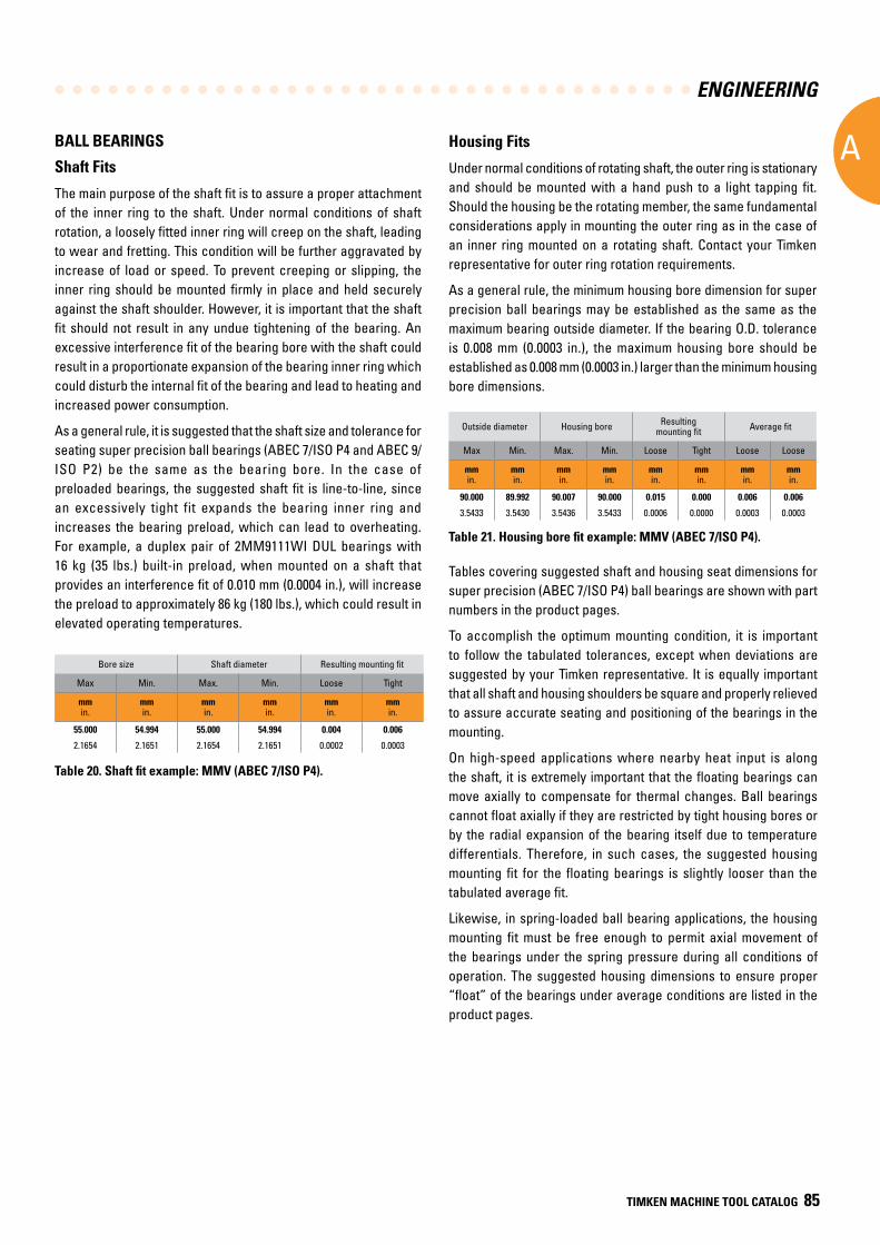
ENGINEERING
A
TIMKEN MACHINE TOOL CATALOG 85
BALL BEARINGS
Shaft Fits
The main purpose of the shaft fit is to assure a proper attachment of the inner ring to the shaft. Under normal conditions of shaft rotation, a loosely fitted inner ring will creep on the shaft, leading to wear and fretting. This condition will be further aggravated by increase of load or speed. To prevent creeping or slipping, the inner ring should be mounted firmly in place and held securely against the shaft shoulder. However, it is important that the shaft fit should not result in any undue tightening of the bearing. An excessive interference fit of the bearing bore with the shaft could result in a proportionate expansion of the bearing inner ring which could disturb the internal fit of the bearing and lead to heating and increased power consumption.
As a general rule, it is suggested that the shaft size and tolerance for seating super precision ball bearings (ABEC 7/ISO P4 and ABEC 9/ ISO P2) be the same as the bearing bore. In the case of preloaded bearings, the suggested shaft fit is line-to-line, since an excessively tight fit expands the bearing inner ring and increases the bearing preload, which can lead to overheating. For example, a duplex pair of 2MM9111WI DUL bearings with 16 kg (35 lbs.) built-in preload, when mounted on a shaft that provides an interference fit of 0.010 mm (0.0004 in.), will increase the preload to approximately 86 kg (180 lbs.), which could result in elevated operating temperatures.
Bore size Shaft diameter Resulting mounting fit
Max Min. Max. Min. Loose Tight
mmin.
mmin.
mmin.
mmin.
mmin.
mmin.
55.000 54.994 55.000 54.994 0.004 0.006
2.1654 2.1651 2.1654 2.1651 0.0002 0.0003
Table 20. Shaft fit example: MMV (ABEC 7/ISO P4).
Tables covering suggested shaft and housing seat dimensions for super precision (ABEC 7/ISO P4) ball bearings are shown with part numbers in the product pages.
To accomplish the optimum mounting condition, it is important to follow the tabulated tolerances, except when deviations are suggested by your Timken representative. It is equally important that all shaft and housing shoulders be square and properly relieved to assure accurate seating and positioning of the bearings in the mounting.
On high-speed applications where nearby heat input is along the shaft, it is extremely important that the floating bearings can move axially to compensate for thermal changes. Ball bearings cannot float axially if they are restricted by tight housing bores or by the radial expansion of the bearing itself due to temperature differentials. Therefore, in such cases, the suggested housing mounting fit for the floating bearings is slightly looser than the tabulated average fit.
Likewise, in spring-loaded ball bearing applications, the housing mounting fit must be free enough to permit axial movement of the bearings under the spring pressure during all conditions of operation. The suggested housing dimensions to ensure proper “float” of the bearings under average conditions are listed in the product pages.
Housing Fits
Under normal conditions of rotating shaft, the outer ring is stationary and should be mounted with a hand push to a light tapping fit. Should the housing be the rotating member, the same fundamental considerations apply in mounting the outer ring as in the case of an inner ring mounted on a rotating shaft. Contact your Timken representative for outer ring rotation requirements.
As a general rule, the minimum housing bore dimension for super precision ball bearings may be established as the same as the maximum bearing outside diameter. If the bearing O.D. tolerance is 0.008 mm (0.0003 in.), the maximum housing bore should be established as 0.008 mm (0.0003 in.) larger than the minimum housing bore dimensions.
Outside diameter Housing bore Resulting mounting fit Average fit
Max Min. Max. Min. Loose Tight Loose Loose
mmin.
mmin.
mmin.
mmin.
mmin.
mmin.
mmin.
mmin.
90.000 89.992 90.007 90.000 0.015 0.000 0.006 0.006
3.5433 3.5430 3.5436 3.5433 0.0006 0.0000 0.0003 0.0003
Table 21. Housing bore fit example: MMV (ABEC 7/ISO P4).
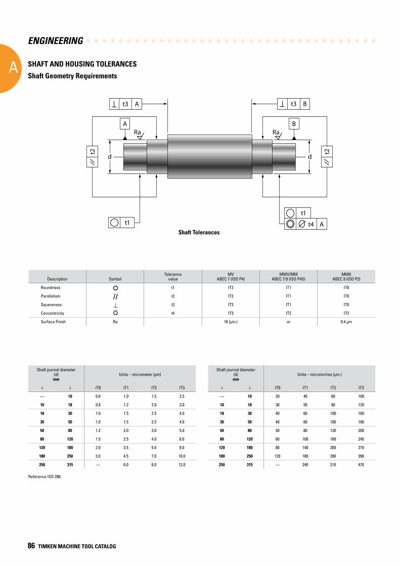
ENGINEERING
A
86 TIMKEN MACHINE TOOL CATALOG
d
ARa
At3
t1
t2
d
BRa
Bt3
t1
t2
At4
Description SymbolTolerance
valueMV
ABEC 7 (ISO P4)MMV/MM
ABEC 7/9 (ISO P4S)MMX
ABEC 9 (ISO P2)
Roundness t1 IT2 IT1 IT0
Parallelism t2 IT2 IT1 IT0
Squareness t3 IT2 IT1 IT0
Concentricity t4 IT3 IT2 IT2
Surface Finish Ra 16 (µin.) or 0.4 µm
Shaft journal diameter (d)mm
Units – micrometer (µm)Shaft journal diameter
(d) mm
Units – microinches (µin.)
> ≤ IT0 IT1 IT2 IT3 > ≤ IT0 IT1 IT2 IT3
— 10 0.6 1.0 1.5 2.5 — 10 20 40 60 100
10 18 0.8 1.2 2.0 3.0 10 18 30 50 80 120
18 30 1.0 1.5 2.5 4.0 18 30 40 60 100 160
30 50 1.0 1.5 2.5 4.0 30 50 40 60 100 160
50 80 1.2 2.0 3.0 5.0 50 80 50 80 120 200
80 120 1.5 2.5 4.0 6.0 80 120 60 100 160 240
120 180 2.0 3.5 5.0 8.0 120 180 80 140 200 310
180 250 3.0 4.5 7.0 10.0 180 250 120 180 280 390
250 315 — 6.0 8.0 12.0 250 315 — 240 310 470
//
Shaft Tolerances
SHAFT AND HOUSING TOLERANCES
Shaft Geometry Requirements
Reference ISO 286.
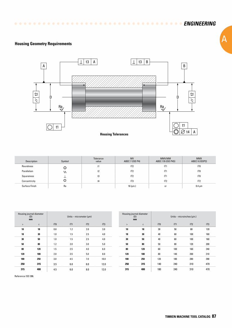
ENGINEERING
A
TIMKEN MACHINE TOOL CATALOG 87
Housing Geometry Requirements
Description SymbolTolerance
valueMV
ABEC 7 (ISO P4)MMV/MM
ABEC 7/9 (ISO P4S)MMX
ABEC 9 (ISOP2)
Roundness t1 IT2 IT1 IT0
Parallelism t2 IT2 IT1 IT0
Squareness t3 IT2 IT1 IT0
Concentricity t4 IT3 IT2 IT2
Surface Finish Ra 16 (µin.) or 0.4 µm
Housing journal diameter (D)mm
Units – micrometer (µm)Housing journal diameter
(D) mm
Units – microinches (µin.)
> ≤ IT0 IT1 IT2 IT3 > ≤ IT0 IT1 IT2 IT3
10 18 0.8 1.2 2.0 3.0 10 18 30 50 80 120
18 30 1.0 1.5 2.5 4.0 18 30 40 60 100 160
30 50 1.0 1.5 2.5 4.0 30 50 40 60 100 160
50 80 1.2 2.0 3.0 5.0 50 80 50 80 120 200
80 120 1.5 2.5 4.0 6.0 80 120 60 100 160 240
120 180 2.0 3.5 5.0 8.0 120 180 80 140 200 310
180 250 3.0 4.5 7.0 10.0 180 250 120 180 280 390
250 315 3.5 6.0 8.0 12.0 250 315 140 240 310 470
315 400 4.5 6.0 8.0 12.0 315 400 180 240 310 470
Housing Tolerances
t1
At4
At3
t1
Ra
t2
D
ABt3
Ra
t2
D
B
Reference ISO 286.
ENGINEERING
A
88 TIMKEN MACHINE TOOL CATALOG
MOUNTING DESIGNSObtaining good spindle accuracy depends not only on selecting the proper precision bearings but also on the following factors:
• Good design and machining of the components that support the bearing (roundness and alignment of the seats, squareness of backing shoulders of both the spindle and the housing, and surface finish).
• Correct use of information given on bearings.
• Correct fitting practices.
• Appropriate bearing setting.
Selection of the most appropriate mounting design is largely dictated by optimizing the stiffness, speedability and ease of assembly.
DESIGN AND ACCURACY OF MOUNTING SURFACES
The total runout of a spindle-bearing-housing system is a combination of the runout of each component. A precision bearing will assume the shape of the spindle and perpetuate whatever runout is present. If the runout is caused by a defective housing, the spindle and bearing will simply transmit the error to the workpiece. Therefore, particular attention needs to be paid to the design and accuracy of the mounting surfaces.
The primary function of the inner or outer ring seat and abutment is to positively establish the location and alignment of the bearing under all loading and operating conditions. To achieve optimum bearing performance, it is essential to design housing seats and abutments that are round and square in alignment with the spindle axis. Shoulders must be of sufficient section and design to resist axial deflection under load. The shoulder diameters should be respected to help obtain optimum bearing performance.
HOUSING DESIGN
Housings are usually made of cast iron or steel and are generally heat-treated to lessen possible distortion. For smaller high-speed applications, steel housings are preferred.
The bore of the housing should be ground or bored and checked at a number of points throughout its length and diameter to ensure that it is round and does not taper.
It is preferable to mount the bearings in one casting; this permits machining the two housing bores in one setting, as well as accurate alignment of the bearings.
In many cases of machine design, it is advantageous to employ a subhousing or a steel sleeve between the outer ring of the bearing and the machine frame, thus allowing assembly of the bearings on the shaft and insertion of the entire unit into the machine frame. This method also provides a surface of proper hardness where machine frames are made of a material that has a low Brinell value, such as aluminum and other soft metals.
Shaft shoulders and housing shoulders should be square and true, and should be of such diameters as to meet the suggestions shown with the part numbers given. The choice between fillets and undercut reliefs rests with the individual shaft design and conditions surrounding its normal use. Suggested housing geometry requirements are discussed on pages 85 and 87.
Where screws are used to fasten end caps into the main housing, adequate section should be left between the screw hole and the housing bore. This is required to prevent distortion of the housing bore when the screws are tightened and the covers or others parts are pulled tightly into place.
Prior to assembly, shafts and housings, as well as all lubricant holes and channels, should be cleaned thoroughly to remove all chips and particles that may be carried by the lubricant into the bearings and cause bearing damage.
HOUSING SEALS
A labyrinth combination of slinger and end cover provides a highly effective seal against the intrusion of foreign matter. This seal is suggested for use over a wide range of speeds. For slower-speed applications, a combination of slinger and a commercial contact-type seal is usually employed.
Slingers should be machined all over to assure true-running. Their diameters should be concentric with the bore. The outside diameter of the slinger is often tapered to throw off cutting compounds, coolants, etc., from the point at which such liquids may enter the spindle. A drip or run-off groove adjacent to the open lip of the end cover is highly desirable and practical.
The axial clearances of the internal faces between slinger and end cover should be about 1.600 mm (0.0629 in.). The first radial clearance opening on any design through which liquid may pass should be made very close, about 0.089 mm (0.0035 in.) on a side. The inner radial clearances should be between 0.380 mm (0.0149 in.) and 0.190 mm (0.0075 in.).
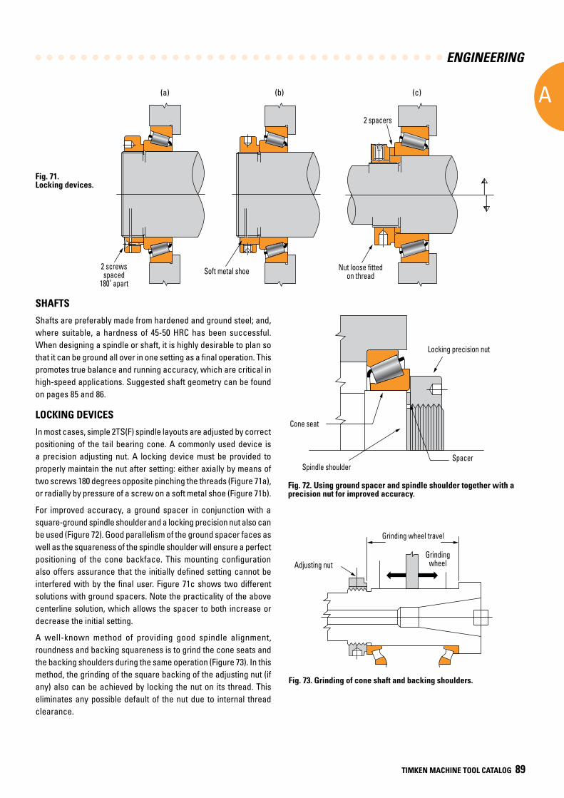
ENGINEERING
A
TIMKEN MACHINE TOOL CATALOG 89
SHAFTS
Shafts are preferably made from hardened and ground steel; and, where suitable, a hardness of 45-50 HRC has been successful. When designing a spindle or shaft, it is highly desirable to plan so that it can be ground all over in one setting as a final operation. This promotes true balance and running accuracy, which are critical in high-speed applications. Suggested shaft geometry can be found on pages 85 and 86.
LOCKING DEVICES
In most cases, simple 2TS(F) spindle layouts are adjusted by correct positioning of the tail bearing cone. A commonly used device is a precision adjusting nut. A locking device must be provided to properly maintain the nut after setting: either axially by means of two screws 180 degrees opposite pinching the threads (Figure 71a), or radially by pressure of a screw on a soft metal shoe (Figure 71b).
For improved accuracy, a ground spacer in conjunction with a square-ground spindle shoulder and a locking precision nut also can be used (Figure 72). Good parallelism of the ground spacer faces as well as the squareness of the spindle shoulder will ensure a perfect positioning of the cone backface. This mounting configuration also offers assurance that the initially defined setting cannot be interfered with by the final user. Figure 71c shows two different solutions with ground spacers. Note the practicality of the above centerline solution, which allows the spacer to both increase or decrease the initial setting.
A well-known method of providing good spindle alignment, roundness and backing squareness is to grind the cone seats and the backing shoulders during the same operation (Figure 73). In this method, the grinding of the square backing of the adjusting nut (if any) also can be achieved by locking the nut on its thread. This eliminates any possible default of the nut due to internal thread clearance.
Fig. 73. Grinding of cone shaft and backing shoulders.
Fig. 72. Using ground spacer and spindle shoulder together with a precision nut for improved accuracy.
Grinding wheel travel
Grinding wheelAdjusting nutAdjusting nut
Grinding wheel travel
Grinding wheel
Locking precision nut
Spacer
Cone seat
Spindle shoulder
Cone seat
Locking precision nut
Spindle shoulderSpacer
(a) (b) (c)
2 screwsspaced
180˚ apartSoft metal shoe Nut loose fitted
on thread
2 spacers
Fig. 71. Locking devices.
2 screwsspaced
180˚ apartSoft metal shoe
2 spacers
Nut loose fittedon thread
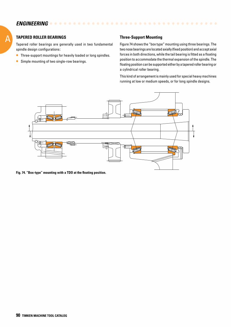
ENGINEERING
A
90 TIMKEN MACHINE TOOL CATALOG
Fig. 74. “Box-type” mounting with a TDO at the floating position.
Three-Support Mounting
Figure 74 shows the “box type” mounting using three bearings. The two nose bearings are located axially (fixed position) and accept axial forces in both directions, while the tail bearing is fitted as a floating position to accommodate the thermal expansion of the spindle. The floating position can be supported either by a tapered roller bearing or a cylindrical roller bearing.
This kind of arrangement is mainly used for special heavy machines running at low or medium speeds, or for long spindle designs.
TAPERED ROLLER BEARINGS
Tapered roller bearings are generally used in two fundamental spindle design configurations :
• Three-support mountings for heavily loaded or long spindles.
• Simple mounting of two single-row bearings.
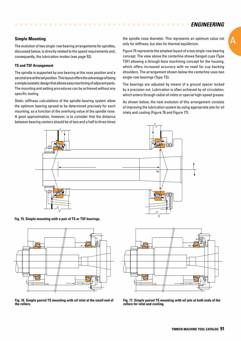
ENGINEERING
A
TIMKEN MACHINE TOOL CATALOG 91
Simple Mounting
The evolution of two single-row bearing arrangements for spindles, discussed below, is directly related to the speed requirements and, consequently, the lubrication modes (see page 52).
TS and TSF Arrangement
The spindle is supported by one bearing at the nose position and a second one at the tail position. This layout offers the advantage of being a simple isostatic design that allows easy machining of adjacent parts. The mounting and setting procedures can be achieved without any specific tooling.
Static stiffness calculations of the spindle-bearing system allow the optimum bearing spread to be determined precisely for each mounting, as a function of the overhung value of the spindle nose. A good approximation, however, is to consider that the distance between bearing centers should be of two and a half to three times
Fig. 76. Simple paired TS mounting with oil inlet at the small end of the rollers.
Fig. 77. Simple paired TS mounting with oil jets at both ends of the rollers for inlet and cooling.
the spindle nose diameter. This represents an optimum value not only for stiffness, but also for thermal equilibrium.
Figure 75 represents the simplest layout of a two single-row bearing concept. The view above the centerline shows flanged cups (Type TSF) allowing a through-bore machining concept for the housing, which offers increased accuracy with no need for cup backing shoulders. The arrangement shown below the centerline uses two single-row bearings (Type TS).
The bearings are adjusted by means of a ground spacer locked by a precision nut. Lubrication is often achieved by oil circulation, which enters through radial oil inlets or special high-speed grease.
As shown below, the next evolution of this arrangement consists of improving the lubrication system by using appropriate jets for oil inlets and cooling (Figure 76 and Figure 77).
Fig. 75. Simple mounting with a pair of TS or TSF bearings.
2.5 to 3 times d(theoretical) d
TS and TSF Arrangement
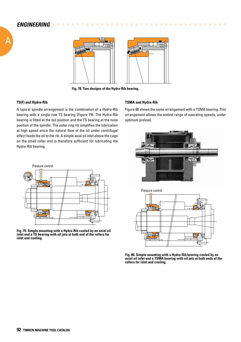
ENGINEERING
A
92 TIMKEN MACHINE TOOL CATALOG
Fig. 78. Two designs of the Hydra-Rib bearing.
TS(F) and Hydra-Rib
A typical spindle arrangement is the combination of a Hydra-Rib
bearing with a single-row TS bearing (Figure 79). The Hydra-Rib bearing is fitted at the tail position and the TS bearing at the nose position of the spindle. The outer ring rib simplifies the lubrication at high speed since the natural flow of the oil under centrifugal effect feeds the oil to the rib. A simple axial oil inlet above the cage on the small roller end is therefore sufficient for lubricating the Hydra-Rib bearing.
Fig. 79. Simple mounting with a Hydra-Rib cooled by an axial oil inlet and a TS bearing with oil jets at both end of the rollers for inlet and cooling.
Pressure controlPressure control
TSMA and Hydra-Rib
Figure 80 shows the same arrangement with a TSMA bearing. This arrangement allows the widest range of operating speeds, under optimum preload.
Fig. 80. Simple mounting with a Hydra-Rib bearing cooled by an axial oil inlet and a TSMA bearing with oil jets at both ends of the rollers for inlet and cooling.
Pressure controlPressure control
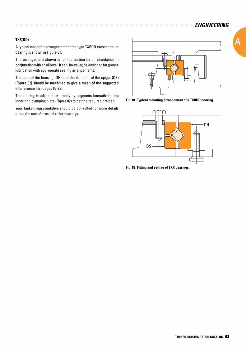
ENGINEERING
A
TIMKEN MACHINE TOOL CATALOG 93
TXR(DO)
A typical mounting arrangement for the type TXRDO crossed roller bearing is shown in Figure 81.
The arrangement shown is for lubrication by oil circulation in conjunction with an oil level. It can, however, be designed for grease lubrication with appropriate sealing arrangements.
The bore of the housing (DH) and the diameter of the spigot (DS) (Figure 82) should be machined to give a mean of the suggested interference fits (pages 82-83).
The bearing is adjusted externally by segments beneath the top inner ring clamping plate (Figure 82) to get the required preload.
Your Timken representative should be consulted for more details about the use of crossed roller bearings.
DS
DH
Fig. 81. Typical mounting arrangement of a TXRDO bearing.
Fig. 82. Fitting and setting of TXR bearings.
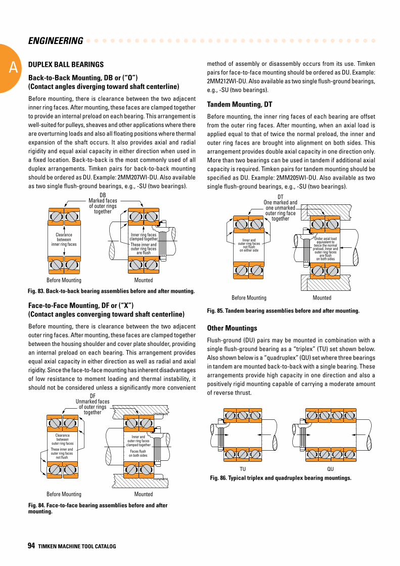
ENGINEERING
A
94 TIMKEN MACHINE TOOL CATALOG
Back-to-Back Mounting, DB or (“O”) (Contact angles diverging toward shaft centerline)
Before mounting, there is clearance between the two adjacent inner ring faces. After mounting, these faces are clamped together to provide an internal preload on each bearing. This arrangement is well-suited for pulleys, sheaves and other applications where there are overturning loads and also all floating positions where thermal expansion of the shaft occurs. It also provides axial and radial rigidity and equal axial capacity in either direction when used in a fixed location. Back-to-back is the most commonly used of all duplex arrangements. Timken pairs for back-to-back mounting should be ordered as DU. Example: 2MM207WI-DU. Also available as two single flush-ground bearings, e.g., -SU (two bearings).
Face-to-Face Mounting, DF or (“X”) (Contact angles converging toward shaft centerline)
Before mounting, there is clearance between the two adjacent outer ring faces. After mounting, these faces are clamped together between the housing shoulder and cover plate shoulder, providing an internal preload on each bearing. This arrangement provides equal axial capacity in either direction as well as radial and axial rigidity. Since the face-to-face mounting has inherent disadvantages of low resistance to moment loading and thermal instability, it should not be considered unless a significantly more convenient
method of assembly or disassembly occurs from its use. Timken pairs for face-to-face mounting should be ordered as DU. Example: 2MM212WI-DU. Also available as two single flush-ground bearings, e.g., -SU (two bearings).
Tandem Mounting, DT
Before mounting, the inner ring faces of each bearing are offset from the outer ring faces. After mounting, when an axial load is applied equal to that of twice the normal preload, the inner and outer ring faces are brought into alignment on both sides. This arrangement provides double axial capacity in one direction only. More than two bearings can be used in tandem if additional axial capacity is required. Timken pairs for tandem mounting should be specified as DU. Example: 2MM205WI-DU. Also available as two single flush-ground bearings, e.g., -SU (two bearings).
Fig. 85. Tandem bearing assemblies before and after mounting.
DTOne marked andone unmarkedouter ring face
together
Before Mounting Mounted
Under axial loadequivalent to
twice the normalpreload. Inner and
outer ring facesare flush
on both sides
Inner andouter ring faces
not flushon either side
DTOne marked andone unmarkedouter ring face
together
Before Mounting Mounted
Inner andouter ring faces
not flushon either side
Under axial loadequivalent to
twice the normalpreload. Inner and
outer ring facesare flush
on both sides
Other Mountings
Flush-ground (DU) pairs may be mounted in combination with a single flush-ground bearing as a “triplex” (TU) set shown below. Also shown below is a “quadruplex” (QU) set where three bearings in tandem are mounted back-to-back with a single bearing. These arrangements provide high capacity in one direction and also a positively rigid mounting capable of carrying a moderate amount of reverse thrust.
QUTU
Fig. 86. Typical triplex and quadruplex bearing mountings.
DUPLEX BALL BEARINGS
Fig. 84. Face-to-face bearing assemblies before and after mounting.
DFUnmarked faces
of outer ringstogether
Before Mounting Mounted
Clearancebetween
outer ring faces
These inner andouter ring faces
not flush
Inner and outer ring faces
clamped together
Faces flushon both sides
DFUnmarked faces
of outer ringstogether
Before Mounting Mounted
Clearancebetween
outer ring faces
Inner and outer ring faces
clamped togetherThese inner andouter ring faces
not flushFaces flush
on both sides
Fig. 83. Back-to-back bearing assemblies before and after mounting.
DBMarked facesof outer rings
together
Before Mounting Mounted
Clearancebetween
inner ring faces
Inner ring facesclamped togetherThese inner andouter ring faces
are flush
DBMarked facesof outer rings
together
Before Mounting Mounted
Clearancebetween
inner ring faces
Inner ring facesclamped togetherThese inner andouter ring faces
are flush
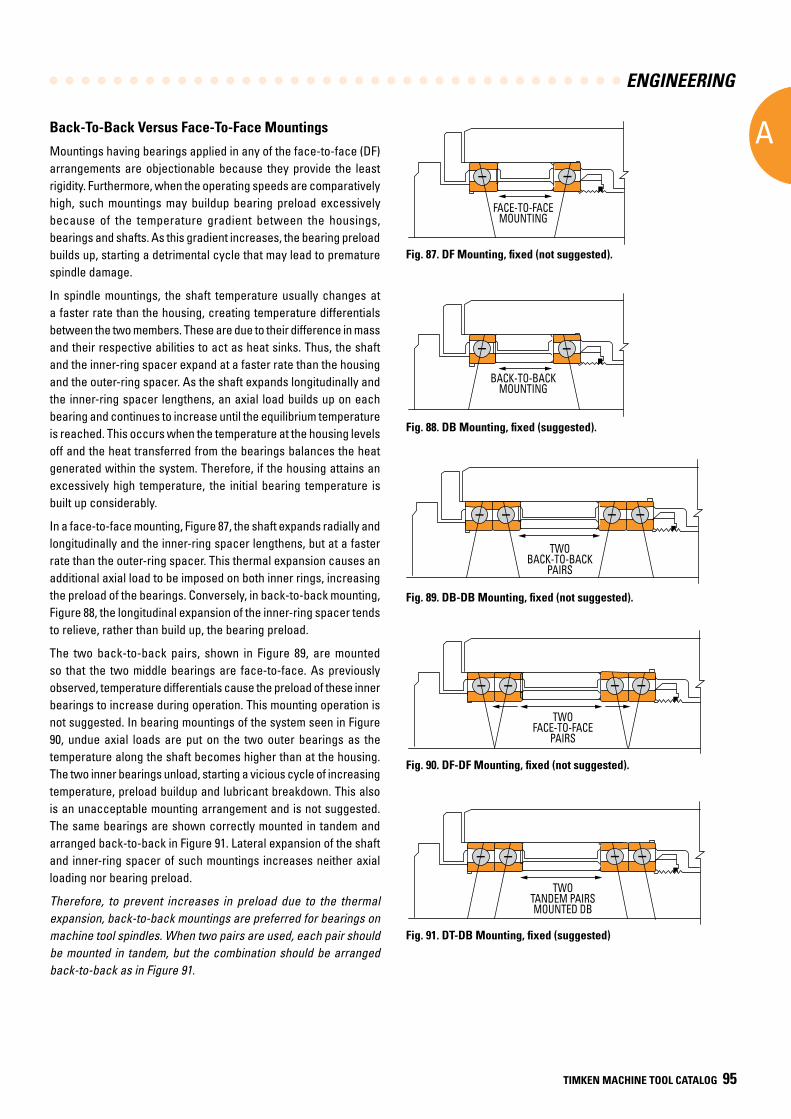
ENGINEERING
A
TIMKEN MACHINE TOOL CATALOG 95
Back-To-Back Versus Face-To-Face Mountings
Mountings having bearings applied in any of the face-to-face (DF) arrangements are objectionable because they provide the least rigidity. Furthermore, when the operating speeds are comparatively high, such mountings may buildup bearing preload excessively because of the temperature gradient between the housings, bearings and shafts. As this gradient increases, the bearing preload builds up, starting a detrimental cycle that may lead to premature spindle damage.
In spindle mountings, the shaft temperature usually changes at a faster rate than the housing, creating temperature differentials between the two members. These are due to their difference in mass and their respective abilities to act as heat sinks. Thus, the shaft and the inner-ring spacer expand at a faster rate than the housing and the outer-ring spacer. As the shaft expands longitudinally and the inner-ring spacer lengthens, an axial load builds up on each bearing and continues to increase until the equilibrium temperature is reached. This occurs when the temperature at the housing levels off and the heat transferred from the bearings balances the heat generated within the system. Therefore, if the housing attains an excessively high temperature, the initial bearing temperature is built up considerably.
In a face-to-face mounting, Figure 87, the shaft expands radially and longitudinally and the inner-ring spacer lengthens, but at a faster rate than the outer-ring spacer. This thermal expansion causes an additional axial load to be imposed on both inner rings, increasing the preload of the bearings. Conversely, in back-to-back mounting, Figure 88, the longitudinal expansion of the inner-ring spacer tends to relieve, rather than build up, the bearing preload.
The two back-to-back pairs, shown in Figure 89, are mounted so that the two middle bearings are face-to-face. As previously observed, temperature differentials cause the preload of these inner bearings to increase during operation. This mounting operation is not suggested. In bearing mountings of the system seen in Figure 90, undue axial loads are put on the two outer bearings as the temperature along the shaft becomes higher than at the housing. The two inner bearings unload, starting a vicious cycle of increasing temperature, preload buildup and lubricant breakdown. This also is an unacceptable mounting arrangement and is not suggested. The same bearings are shown correctly mounted in tandem and arranged back-to-back in Figure 91. Lateral expansion of the shaft and inner-ring spacer of such mountings increases neither axial loading nor bearing preload.
Therefore, to prevent increases in preload due to the thermal expansion, back-to-back mountings are preferred for bearings on machine tool spindles. When two pairs are used, each pair should be mounted in tandem, but the combination should be arranged back-to-back as in Figure 91.
Fig. 87. DF Mounting, fixed (not suggested).
Fig. 88. DB Mounting, fixed (suggested).
Fig. 89. DB-DB Mounting, fixed (not suggested).
Fig. 90. DF-DF Mounting, fixed (not suggested).
Fig. 91. DT-DB Mounting, fixed (suggested)
FACE-TO-FACEMOUNTING
FACE-TO-FACEMOUNTING
BACK-TO-BACKMOUNTING
BACK-TO-BACKMOUNTING
TWO BACK-TO-BACK
PAIRS
TWO BACK-TO-BACK
PAIRS
TWO FACE-TO-FACE
PAIRS
TWO FACE-TO-FACE
PAIRS
TWO TANDEM PAIRS MOUNTED DB
TWO TANDEM PAIRS MOUNTED DB
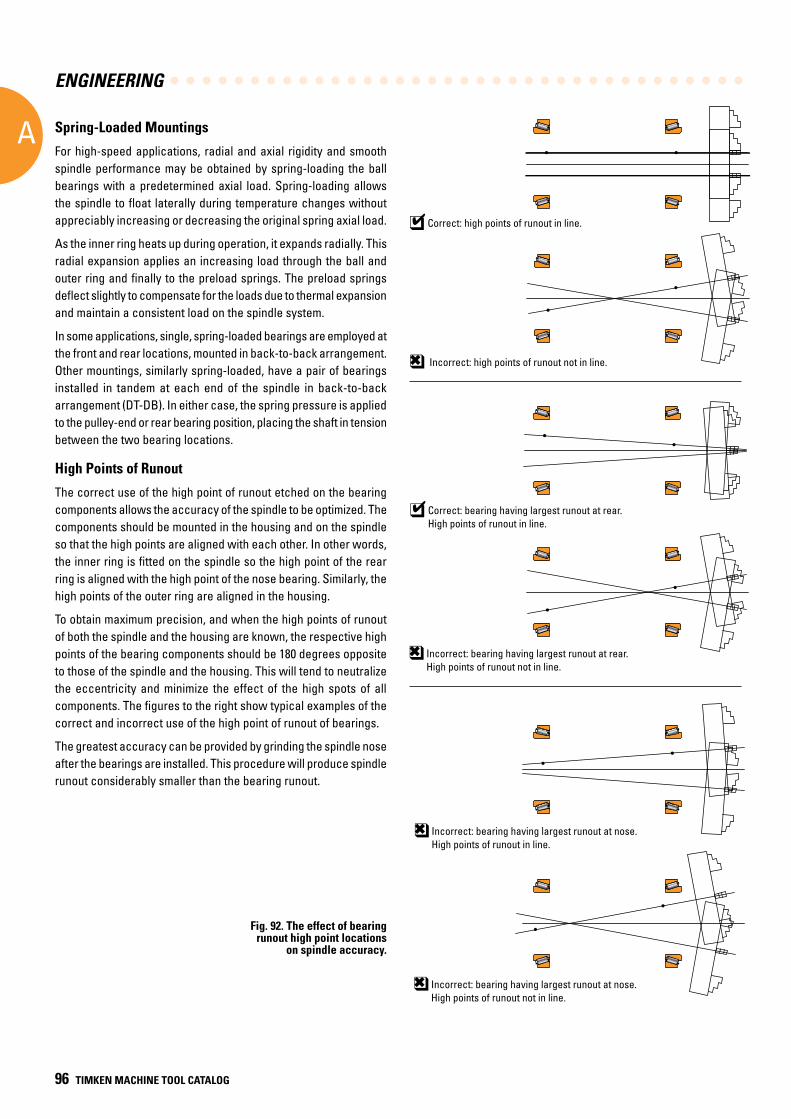
ENGINEERING
A
96 TIMKEN MACHINE TOOL CATALOG
Spring-Loaded Mountings
For high-speed applications, radial and axial rigidity and smooth spindle performance may be obtained by spring-loading the ball bearings with a predetermined axial load. Spring-loading allows the spindle to float laterally during temperature changes without appreciably increasing or decreasing the original spring axial load.
As the inner ring heats up during operation, it expands radially. This radial expansion applies an increasing load through the ball and outer ring and finally to the preload springs. The preload springs deflect slightly to compensate for the loads due to thermal expansion and maintain a consistent load on the spindle system.
In some applications, single, spring-loaded bearings are employed at the front and rear locations, mounted in back-to-back arrangement. Other mountings, similarly spring-loaded, have a pair of bearings installed in tandem at each end of the spindle in back-to-back arrangement (DT-DB). In either case, the spring pressure is applied to the pulley-end or rear bearing position, placing the shaft in tension between the two bearing locations.
High Points of Runout
The correct use of the high point of runout etched on the bearing components allows the accuracy of the spindle to be optimized. The components should be mounted in the housing and on the spindle so that the high points are aligned with each other. In other words, the inner ring is fitted on the spindle so the high point of the rear ring is aligned with the high point of the nose bearing. Similarly, the high points of the outer ring are aligned in the housing.
To obtain maximum precision, and when the high points of runout of both the spindle and the housing are known, the respective high points of the bearing components should be 180 degrees opposite to those of the spindle and the housing. This will tend to neutralize the eccentricity and minimize the effect of the high spots of all components. The figures to the right show typical examples of the correct and incorrect use of the high point of runout of bearings.
The greatest accuracy can be provided by grinding the spindle nose after the bearings are installed. This procedure will produce spindle runout considerably smaller than the bearing runout.
Correct: high points of runout in line.4q
Incorrect: high points of runout not in line.6q
Correct: bearing having largest runout at rear.High points of runout in line.
4q
Incorrect: bearing having largest runout at rear.High points of runout not in line.
6q
Incorrect: bearing having largest runout at nose. High points of runout not in line.
6q
Incorrect: bearing having largest runout at nose. High points of runout in line.
6q
Fig. 92. The effect of bearing runout high point locations
on spindle accuracy.
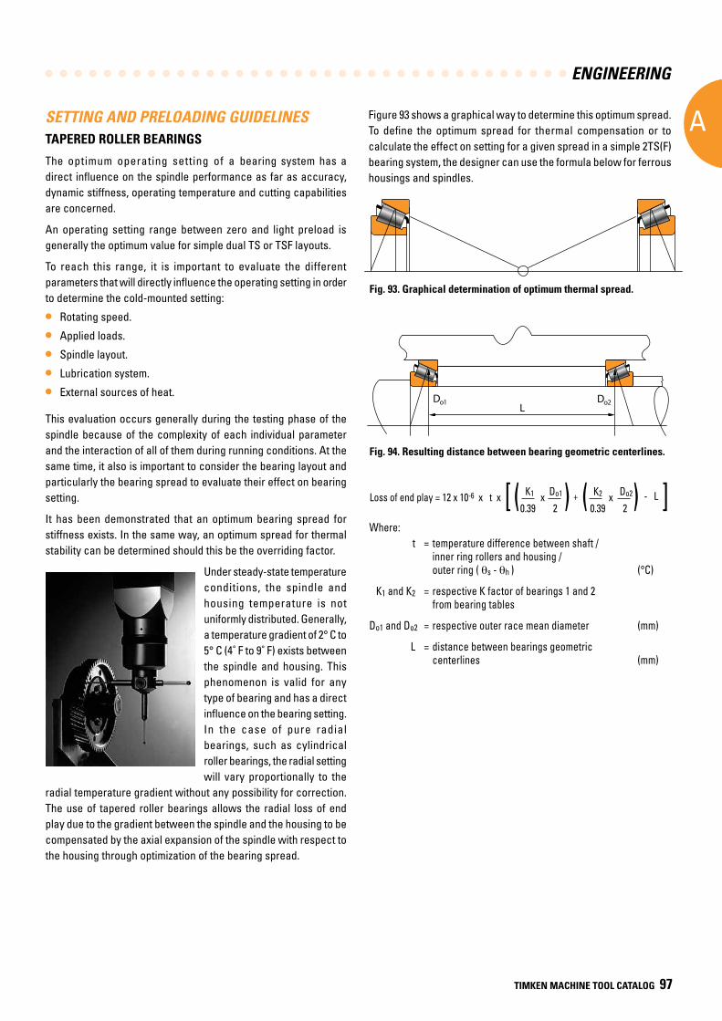
ENGINEERING
A
TIMKEN MACHINE TOOL CATALOG 97
LDo2Do1
SETTING AND PRELOADING GUIDELINESTAPERED ROLLER BEARINGS
The optimum operating setting of a bearing system has a direct influence on the spindle performance as far as accuracy, dynamic stiffness, operating temperature and cutting capabilities are concerned.
An operating setting range between zero and light preload is generally the optimum value for simple dual TS or TSF layouts.
To reach this range, it is important to evaluate the different parameters that will directly influence the operating setting in order to determine the cold-mounted setting:
• Rotating speed.
• Applied loads.
• Spindle layout.
• Lubrication system.
• External sources of heat.
This evaluation occurs generally during the testing phase of the spindle because of the complexity of each individual parameter and the interaction of all of them during running conditions. At the same time, it also is important to consider the bearing layout and particularly the bearing spread to evaluate their effect on bearing setting.
It has been demonstrated that an optimum bearing spread for stiffness exists. In the same way, an optimum spread for thermal stability can be determined should this be the overriding factor.
Under steady-state temperature conditions, the spindle and housing temperature is not uniformly distributed. Generally, a temperature gradient of 2° C to 5° C (4˚ F to 9˚ F) exists between the spindle and housing. This phenomenon is valid for any type of bearing and has a direct influence on the bearing setting. In the case of pure radial bearings, such as cylindrical roller bearings, the radial setting will vary proportionally to the
radial temperature gradient without any possibility for correction. The use of tapered roller bearings allows the radial loss of end play due to the gradient between the spindle and the housing to be compensated by the axial expansion of the spindle with respect to the housing through optimization of the bearing spread.
Fig. 93. Graphical determination of optimum thermal spread.
Figure 93 shows a graphical way to determine this optimum spread. To define the optimum spread for thermal compensation or to calculate the effect on setting for a given spread in a simple 2TS(F) bearing system, the designer can use the formula below for ferrous housings and spindles.
Where: t = temperature difference between shaft /
inner ring rollers and housing / outer ring ( qs - qh ) (°C)
K1 and K2 = respective K factor of bearings 1 and 2 from bearing tables
Do1 and Do2 = respective outer race mean diameter (mm)
L = distance between bearings geometric centerlines (mm)
Loss of end play = 12 x 10-6 x t x [ ( K1 x Do1 )
+ ( K2 x Do2) - L ] 0.39 2 0.39 2
Fig. 94. Resulting distance between bearing geometric centerlines.
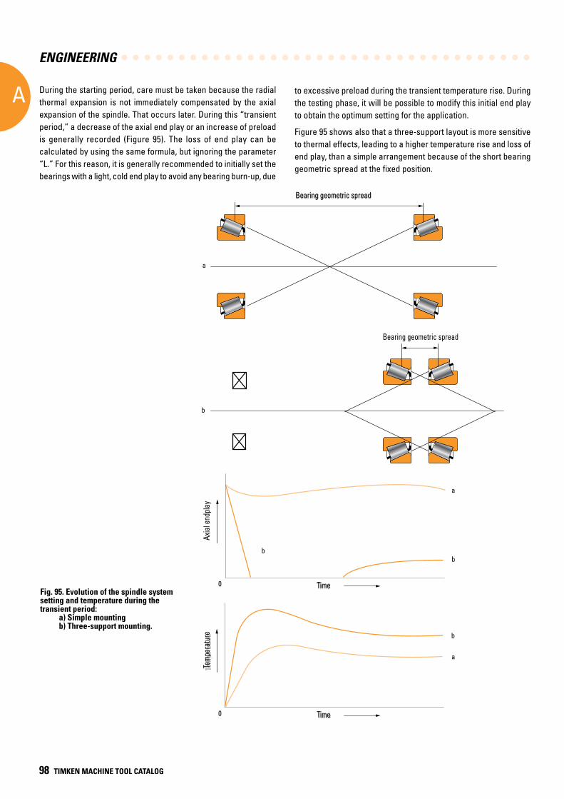
ENGINEERING
A
98 TIMKEN MACHINE TOOL CATALOG
Fig. 95. Evolution of the spindle system setting and temperature during the transient period: a) Simple mounting
b) Three-support mounting.
During the starting period, care must be taken because the radial thermal expansion is not immediately compensated by the axial expansion of the spindle. That occurs later. During this “transient period,” a decrease of the axial end play or an increase of preload is generally recorded (Figure 95). The loss of end play can be calculated by using the same formula, but ignoring the parameter “L.” For this reason, it is generally recommended to initially set the bearings with a light, cold end play to avoid any bearing burn-up, due
to excessive preload during the transient temperature rise. During the testing phase, it will be possible to modify this initial end play to obtain the optimum setting for the application.
Figure 95 shows also that a three-support layout is more sensitive to thermal effects, leading to a higher temperature rise and loss of end play, than a simple arrangement because of the short bearing geometric spread at the fixed position.
Bearing geometric spreadBearing geometric spread
a
Bearing geometric spread
b
Axia
l end
play
TimeTime
TimeTime
Tem
pera
ture
Tem
pera
ture
bb
b
a
a
0
0
Bearing geometric spread
Bearing geometric spread
Time
Time
Axial
endp
layTe
mper
atur
e
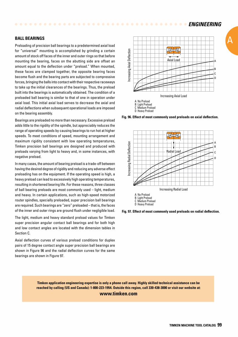
ENGINEERING
A
TIMKEN MACHINE TOOL CATALOG 99
BALL BEARINGS
Preloading of precision ball bearings to a predetermined axial load for “universal” mounting is accomplished by grinding a certain amount of stock off faces of the inner and outer rings so that before mounting the bearing, faces on the abutting side are offset an amount equal to the deflection under “preload.” When mounted, these faces are clamped together, the opposite bearing faces become flush and the bearing parts are subjected to compressive forces, bringing the balls into contact with their respective raceways to take up the initial clearances of the bearings. Thus, the preload built into the bearings is automatically obtained. The condition of a preloaded ball bearing is similar to that of one in operation under axial load. This initial axial load serves to decrease the axial and radial deflections when subsequent operational loads are imposed on the bearing assembly.
Bearings are preloaded no more than necessary. Excessive preload adds little to the rigidity of the spindle, but appreciably reduces the range of operating speeds by causing bearings to run hot at higher speeds. To meet conditions of speed, mounting arrangement and maximum rigidity consistent with low operating temperatures, Timken precision ball bearings are designed and produced with preloads varying from light to heavy and, in some instances, with negative preload.
In many cases, the amount of bearing preload is a trade-off between having the desired degree of rigidity and reducing any adverse effect preloading has on the equipment. If the operating speed is high, a heavy preload can lead to excessively high operating temperatures, resulting in shortened bearing life. For these reasons, three classes of ball bearing preloads are most commonly used – light, medium and heavy. In certain applications, such as high-speed motorized router spindles, specially preloaded, super precision ball bearings are required. Such bearings are “zero” preloaded – that is, the faces of the inner and outer rings are ground flush under negligible load.
The light, medium and heavy standard preload values for Timken super precision angular contact ball bearings and for both high and low contact angles are located with the dimension tables in Section C.
Axial deflection curves of various preload conditions for duplex pairs of 15 degree contact angle super precision ball bearings are shown in Figure 96 and the radial deflection curves for the same bearings are shown in Figure 97.
Timken application engineering expertise is only a phone call away . Highly skilled technical assistance can be reached by calling (US and Canada): 1-800-223-1954 . Outside this region, call 330-438-3000 or visit our website at:
www .timken .com
Fig. 97. Effect of most commonly used preloads on radial deflection.
A
B
C
D
AB
C
D
Incr
easi
ng A
xial
Def
lect
ion
Axial Load
Incr
easi
ng R
adia
l Def
lect
ion
Increasing Radial Load
A No PreloadB Light PreloadC Medium PreloadD Heavy Preload
Increasing Axial Load
A No PreloadB Light Preload C Medium Preload D Heavy Preload
Radial Load
Fig. 96. Effect of most commonly used preloads on axial deflection.
Increasing Axial Load
Increasing Radial Load
Axial Load
Radial Load
A No PreloadB Light Preload C Medium Preload D Heavy Preload
A No PreloadB Light Preload C Medium Preload D Heavy Preload
Incr
easin
g Axia
l Defl
ectio
nIn
crea
sing R
adial
Defl
ectio
n

ENGINEERING
A
100 TIMKEN MACHINE TOOL CATALOG
NOTES
A
AD
Bearing Selection
TIMKEN MACHINE TOOL CATALOG 105
TIMKEN SERVICE CATALOG B105
BB
TAPERED ROLLER BEARINGS
B PRECISION TAPERED ROLLER BEARINGS
Part Numbering Systems . . . . . . . . . . . . . . . . . . . . . . . . . . . . . 103
Introduction . . . . . . . . . . . . . . . . . . . . . . . . . . . . . . . . . . . . . . . . 106
TS Style – Metric, Inch . . . . . . . . . . . . . . . . . . . . . . . . . . . . . . . 108
TSF Style – Metric, Inch . . . . . . . . . . . . . . . . . . . . . . . . . . . . . . 112
TXR Style – Metric, Inch . . . . . . . . . . . . . . . . . . . . . . . . . . . . . 116
TSHR Style – Metric, Inch . . . . . . . . . . . . . . . . . . . . . . . . . . . . 118
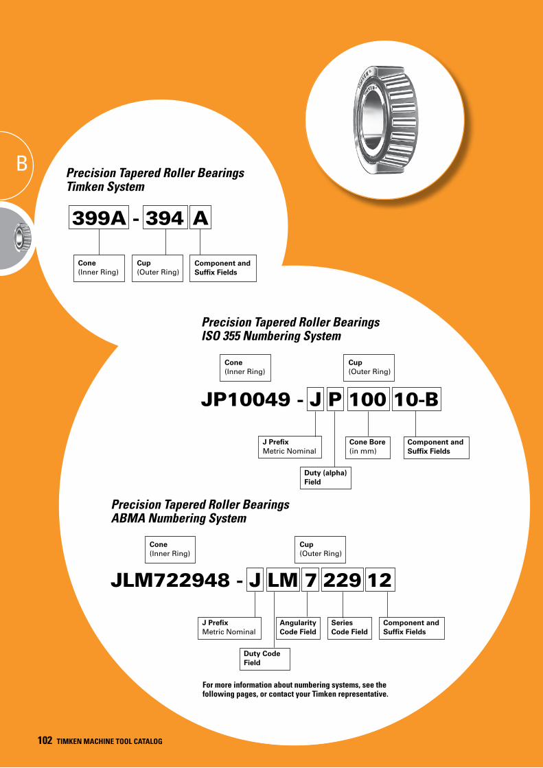
100 TIMKEN MACHINE TOOL CATALOG
B Precision Tapered Roller Bearings Timken System
399A - 394 A
Cone(Inner Ring)
JP10049 - J P 100 10-B
Cone Bore (in mm)
J PrefixMetric Nominal
Duty (alpha) Field
Precision Tapered Roller Bearings ISO 355 Numbering System
JLM722948 - J LM 7 229 12
Angularity Code Field
J PrefixMetric Nominal
Duty Code Field
Series Code Field
Precision Tapered Roller Bearings ABMA Numbering System
Cup(Outer Ring)
Cone(Inner Ring)
Cup(Outer Ring)
Component and Suffix Fields
Component and Suffix Fields
Component and Suffix Fields
Cone(Inner Ring)
Cup(Outer Ring)
For more information about numbering systems, see the following pages, or contact your Timken representative.
102 TIMKEN MACHINE TOOL CATALOG
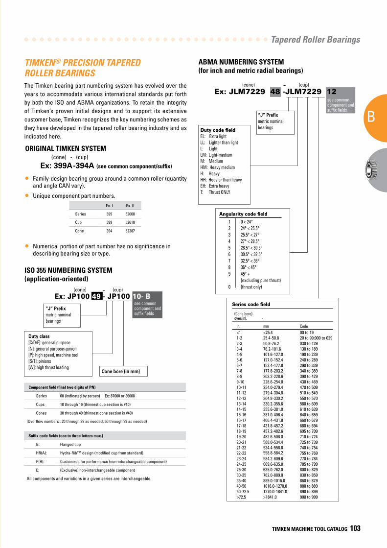
Tapered Roller Bearings
B
TIMKEN MACHINE TOOL CATALOG 103
ORIGINAL TIMKEN SYSTEM (cone) - (cup)
Ex: 399A-394A (see common component/suffix)
• Family-design bearing group around a common roller (quantity and angle CAN vary).
• Unique component part numbers.
• Numerical portion of part number has no significance in describing bearing size or type.
TIMKEN® PRECISION TAPERED ROLLER BEARINGS The Timken bearing part numbering system has evolved over the years to accommodate various international standards put forth by both the ISO and ABMA organizations. To retain the integrity of Timken’s proven initial designs and to support its extensive customer base, Timken recognizes the key numbering schemes as they have developed in the tapered roller bearing industry and as indicated here.
Ex. I Ex. II
Series 395 52000
Cup 399 52618
Cone 394 52387
ABMA NUMBERING SYSTEM(for inch and metric radial bearings)
ISO 355 NUMBERING SYSTEM (application-oriented)
Component field (final two digits of PN)
Series 00 (indicated by zeroes) Ex: 87000 or 36600
Cups 10 through 19 (thinnest cup section is #10)
Cones 30 through 49 (thinnest cone section is #49)
(Overflow numbers : 20 through 29 as needed; 50 through 99 as needed)
Suffix code fields (one to three letters max.)
B: Flanged cup
HR(A): Hydra-RibTM design (modified cup from standard)
P(H): Customized for performance (non-interchangeable component)
E: (Exclusive) non-interchangeable component
All components and variations in a given series are interchangeable.
-
Ex: JP100 49 - JP100 10- B(cone) (cup)
see common component and suffix fields
“J” Prefix metric nominal bearings
Duty class[C/D/F]: general purpose[N]: general purpose+pinion [P]: high speed, machine tool [S/T]: pinions [W]: high thrust loading
Cone bore (in mm)
(cone) (cup)
“J” Prefix metric nominal bearingsDuty code field
EL: Extra lightLL: Lighter than lightL: LightLM: Light-mediumM: MediumHM: Heavy mediumH: HeavyHH: Heavier than heavyEH: Extra heavyT: Thrust ONLY
Angularity code field
Series code field
-
.
Ex: JLM7229 48 -JLM7229 12see common component and suffix fields
1 0 < 24°2 24° < 25.5°3 25.5° < 27°4 27° < 28.5°5 28.5° < 30.5°6 30.5° < 32.5°7 32.5° < 36°8 36° < 45°9 45° + (excluding pure thrust)0 (thrust only)
(Cone bore) over/inl.
in. mm Code<1 <25.4 00 to 191-2 25.4-50.8 20 to 99;000 to 0292-3 50.8-76.2 030 to 1293-4 76.2-101.6 130 to 1894-5 101.6-127.0 190 to 2395-6 127.0-152.4 240 to 2896-7 152.4-177.8 290 to 3397-8 177.8-203.2 340 to 3898-9 203.2-228.6 390 to 4299-10 228.6-254.0 430 to 46910-11 254.0-279.4 470 to 50911-12 279.4-304.8 510 to 54912-13 304.8-330.2 550 to 57013-14 330.2-355.6 580 to 60914-15 355.6-381.0 610 to 63915-16 381.0-406.4 640 to 65916-17 406.4-431.8 660 to 67917-18 431.8-457.2 680 to 69418-19 457.2-482.6 695 to 70919-20 482.6-508.0 710 to 72420-21 508.0-534.4 725 to 73921-22 534.4-558.8 740 to 75422-23 558.8-584.2 755 to 76923-24 584.2-609.6 770 to 78424-25 609.6-635.0 785 to 79925-30 635.0-762.0 800 to 82930-35 762.0-889.0 830 to 85935-40 889.0-1016.0 860 to 87940-50 1016.0-1270.0 880 to 88950-72.5 1270.0-1841.0 890 to 899>72.5 >1841.0 900 to 999
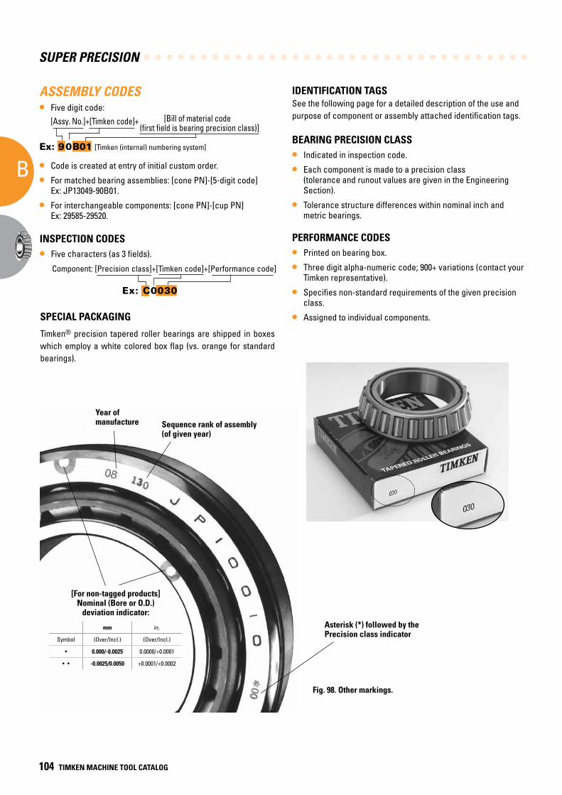
SUPER PRECISION
B
104 TIMKEN MACHINE TOOL CATALOG
ASSEMBLY CODES• Five digit code:
[Assy. No.]+[Timken code]+ [Bill of material code (first field is bearing precision class)]
Ex: 90B01 [Timken (internal) numbering system]
• Code is created at entry of initial custom order.
• For matched bearing assemblies: [cone PN]-[5-digit code] Ex: JP13049-90B01.
• For interchangeable components: [cone PN]-[cup PN] Ex: 29585-29520.
IDENTIFICATION TAGSSee the following page for a detailed description of the use and purpose of component or assembly attached identification tags.
BEARING PRECISION CLASS
• Indicated in inspection code.
• Each component is made to a precision class (tolerance and runout values are given in the Engineering Section).
• Tolerance structure differences within nominal inch and metric bearings.
PERFORMANCE CODES
• Printed on bearing box.
• Three digit alpha-numeric code; 900+ variations (contact your Timken representative).
• Specifies non-standard requirements of the given precision class.
• Assigned to individual components.
INSPECTION CODES
• Five characters (as 3 fields).
Component: [Precision class]+[Timken code]+[Performance code]
Ex: C0030
SPECIAL PACKAGING
Timken® precision tapered roller bearings are shipped in boxes which employ a white colored box flap (vs. orange for standard bearings).
Sequence rank of assembly (of given year)
Year ofmanufacture
Asterisk (*) followed by the Precision class indicator
mm in.
Symbol (Over/Incl.) (Over/Incl.)
• 0.000/-0.0025 0.0000/+0.0001
• • -0.0025/0.0050 +0.0001/+0.0002
[For non-tagged products]Nominal (Bore or O.D.)
deviation indicator:
Fig. 98. Other markings.
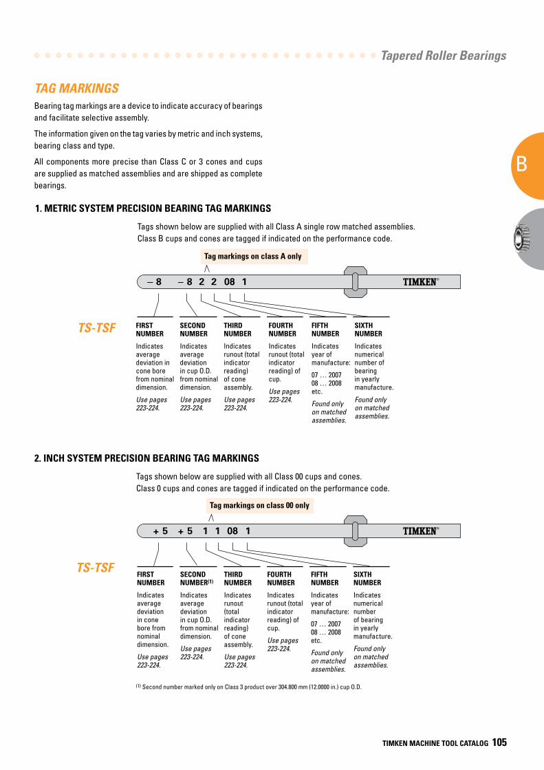
Tapered Roller Bearings
B
TIMKEN MACHINE TOOL CATALOG 105
Tag markings on class A only
Tag markings on class 00 only
TAG MARKINGSBearing tag markings are a device to indicate accuracy of bearings and facilitate selective assembly.
The information given on the tag varies by metric and inch systems, bearing class and type.
All components more precise than Class C or 3 cones and cups are supplied as matched assemblies and are shipped as complete bearings.
TS-TSF
(1) Second number marked only on Class 3 product over 304.800 mm (12.0000 in.) cup O.D.
TS-TSF
Tags shown below are supplied with all Class A single row matched assemblies. Class B cups and cones are tagged if indicated on the performance code.
Tags shown below are supplied with all Class 00 cups and cones. Class 0 cups and cones are tagged if indicated on the performance code.
2. INCH SYSTEM PRECISION BEARING TAG MARKINGS
1. METRIC SYSTEM PRECISION BEARING TAG MARKINGS
FIRST NUMBER
Indicates average deviation in cone bore from nominal dimension.
Use pages 223-224.
SECOND NUMBER
Indicates average deviation in cup O.D. from nominal dimension.
Use pages 223-224.
THIRD NUMBER
Indicates runout (total indicator reading) of cone assembly.
Use pages 223-224.
FOURTH NUMBER
Indicates runout (total indicator reading) of cup.
Use pages 223-224.
FIFTH NUMBER
Indicates year of manufacture:
07 … 2007 08 … 2008 etc.
Found only on matched assemblies.
SIXTH NUMBER
Indicates numerical number of bearing in yearly manufacture.
Found only on matched assemblies.
FIRST NUMBER
Indicates average deviation in cone bore from nominal dimension.
Use pages 223-224.
SECOND NUMBER(1)
Indicates average deviation in cup O.D. from nominal dimension.
Use pages 223-224.
THIRD NUMBER
Indicates runout (total indicator reading) of cone assembly.
Use pages 223-224.
FOURTH NUMBER
Indicates runout (total indicator reading) of cup.
Use pages 223-224.
FIFTH NUMBER
Indicates year of manufacture:
07 … 2007 08 … 2008 etc.
Found only on matched assemblies.
SIXTH NUMBER
Indicates numerical number of bearing in yearly manufacture.
Found only on matched assemblies.
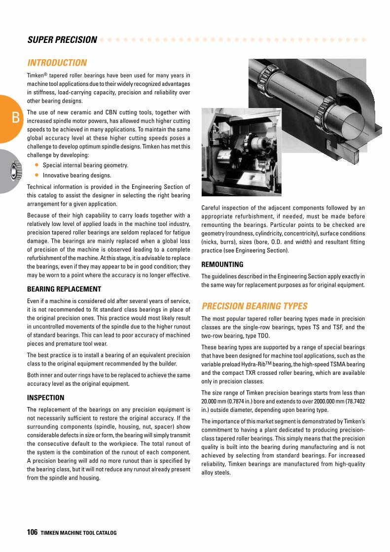
SUPER PRECISION
B
106 TIMKEN MACHINE TOOL CATALOG
INTRODUCTIONTimken® tapered roller bearings have been used for many years in machine tool applications due to their widely recognized advantages in stiffness, load-carrying capacity, precision and reliability over other bearing designs.
The use of new ceramic and CBN cutting tools, together with increased spindle motor powers, has allowed much higher cutting speeds to be achieved in many applications. To maintain the same global accuracy level at these higher cutting speeds poses a challenge to develop optimum spindle designs. Timken has met this challenge by developing:
• Special internal bearing geometry.
• Innovative bearing designs.
Technical information is provided in the Engineering Section of this catalog to assist the designer in selecting the right bearing arrangement for a given application.
Because of their high capability to carry loads together with a relatively low level of applied loads in the machine tool industry, precision tapered roller bearings are seldom replaced for fatigue damage. The bearings are mainly replaced when a global loss of precision of the machine is observed leading to a complete refurbishment of the machine. At this stage, it is advisable to replace the bearings, even if they may appear to be in good condition; they may be worn to a point where the accuracy is no longer effective.
BEARING REPLACEMENT
Even if a machine is considered old after several years of service, it is not recommended to fit standard class bearings in place of the original precision ones. This practice would most likely result in uncontrolled movements of the spindle due to the higher runout of standard bearings. This can lead to poor accuracy of machined pieces and premature tool wear.
The best practice is to install a bearing of an equivalent precision class to the original equipment recommended by the builder.
Both inner and outer rings have to be replaced to achieve the same accuracy level as the original equipment.
INSPECTION
The replacement of the bearings on any precision equipment is not necessarily sufficient to restore the original accuracy. If the surrounding components (spindle, housing, nut, spacer) show considerable defects in size or form, the bearing will simply transmit the consecutive default to the workpiece. The total runout of the system is the combination of the runout of each component. A precision bearing will add no more runout than is specified by the bearing class, but it will not reduce any runout already present from the spindle and housing.
Careful inspection of the adjacent components followed by an appropriate refurbishment, if needed, must be made before remounting the bearings. Particular points to be checked are geometry (roundness, cylindricity, concentricity), surface conditions (nicks, burrs), sizes (bore, O.D. and width) and resultant fitting practice (see Engineering Section).
REMOUNTING
The guidelines described in the Engineering Section apply exactly in the same way for replacement purposes as for original equipment.
PRECISION BEARING TYPESThe most popular tapered roller bearing types made in precision classes are the single-row bearings, types TS and TSF, and the two-row bearing, type TDO.
These bearing types are supported by a range of special bearings that have been designed for machine tool applications, such as the variable preload Hydra-RibTM bearing, the high-speed TSMA bearing and the compact TXR crossed roller bearing, which are available only in precision classes.
The size range of Timken precision bearings starts from less than 20.000 mm (0.7874 in.) bore and extends to over 2000.000 mm (78.7402 in.) outside diameter, depending upon bearing type.
The importance of this market segment is demonstrated by Timken’s commitment to having a plant dedicated to producing precision-class tapered roller bearings. This simply means that the precision quality is built into the bearing during manufacturing and is not achieved by selecting from standard bearings. For increased reliability, Timken bearings are manufactured from high-quality alloy steels.
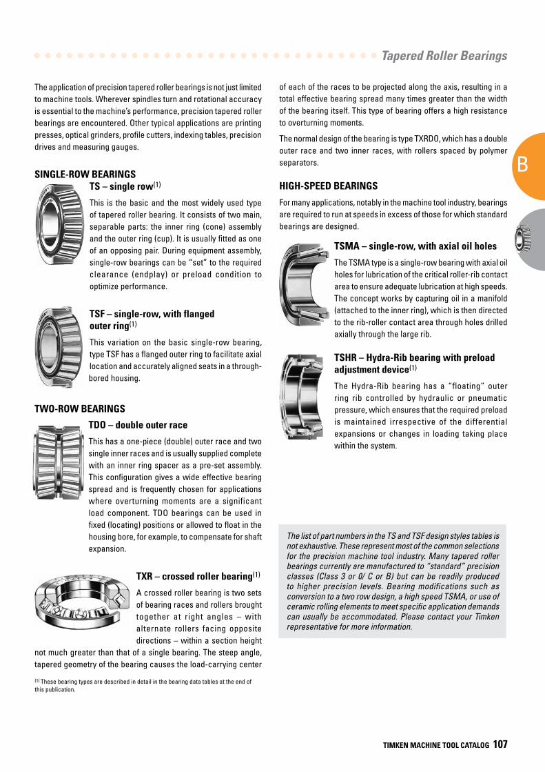
Tapered Roller Bearings
B
TIMKEN MACHINE TOOL CATALOG 107
The application of precision tapered roller bearings is not just limited to machine tools. Wherever spindles turn and rotational accuracy is essential to the machine’s performance, precision tapered roller bearings are encountered. Other typical applications are printing presses, optical grinders, profile cutters, indexing tables, precision drives and measuring gauges.
SINGLE-ROW BEARINGSTS – single row(1)
This is the basic and the most widely used type of tapered roller bearing. It consists of two main, separable parts: the inner ring (cone) assembly and the outer ring (cup). It is usually fitted as one of an opposing pair. During equipment assembly, single-row bearings can be “set” to the required clearance (endplay) or preload condition to optimize performance.
TSF – single-row, with flanged outer ring(1)
This variation on the basic single-row bearing, type TSF has a flanged outer ring to facilitate axial location and accurately aligned seats in a through-bored housing.
TWO-ROW BEARINGS
TDO – double outer race
This has a one-piece (double) outer race and two single inner races and is usually supplied complete with an inner ring spacer as a pre-set assembly. This configuration gives a wide effective bearing spread and is frequently chosen for applications where overturning moments are a significant load component. TDO bearings can be used in fixed (locating) positions or allowed to float in the housing bore, for example, to compensate for shaft expansion.
TXR – crossed roller bearing(1)
A crossed roller bearing is two sets of bearing races and rollers brought together at right angles – with alternate rollers facing opposite directions – within a section height
not much greater than that of a single bearing. The steep angle, tapered geometry of the bearing causes the load-carrying center
of each of the races to be projected along the axis, resulting in a total effective bearing spread many times greater than the width of the bearing itself. This type of bearing offers a high resistance to overturning moments.
The normal design of the bearing is type TXRDO, which has a double outer race and two inner races, with rollers spaced by polymer separators.
HIGH-SPEED BEARINGS
For many applications, notably in the machine tool industry, bearings are required to run at speeds in excess of those for which standard bearings are designed.
TSMA – single-row, with axial oil holes
The TSMA type is a single-row bearing with axial oil holes for lubrication of the critical roller-rib contact area to ensure adequate lubrication at high speeds. The concept works by capturing oil in a manifold (attached to the inner ring), which is then directed to the rib-roller contact area through holes drilled axially through the large rib.
TSHR – Hydra-Rib bearing with preload adjustment device(1)
The Hydra-Rib bearing has a “floating” outer ring rib controlled by hydraulic or pneumatic pressure, which ensures that the required preload is maintained irrespective of the differential expansions or changes in loading taking place within the system.
(1) These bearing types are described in detail in the bearing data tables at the end of this publication.
The list of part numbers in the TS and TSF design styles tables is not exhaustive. These represent most of the common selections for the precision machine tool industry. Many tapered roller bearings currently are manufactured to “standard” precision classes (Class 3 or 0/ C or B) but can be readily produced to higher precision levels. Bearing modifications such as conversion to a two row design, a high speed TSMA, or use of ceramic rolling elements to meet specific application demands can usually be accommodated. Please contact your Timken representative for more information.
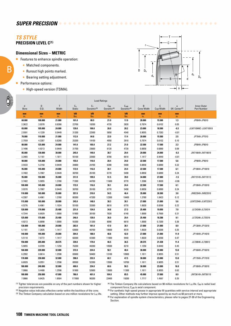
SUPER PRECISION
B
108 TIMKEN MACHINE TOOL CATALOG
TS STYLEPRECISION LEVEL C(1)
Dimensional Sizes – METRIC
• Features to enhance spindle operation:
• Matched components.
• Runout high points marked.
• Bearing setting adjustment.
• Performance options:
• High-speed version (TSMA).
(1) Tighter tolerances are possible on any of the part numbers shown for higher precision requirements.
(2) Negative value indicates effective center within the backface of the cone.(3) The Timken Company calculation based on one million revolutions for L10 life.
(4) The Timken Company life calculations based on 90 million revolutions for L10 life. C90 is radial load component force; Ca90 is axial component.
(5) For synthetic high-speed grease in appropriate fill quantities with service interval and appropriate setting. Other methods may further improve speed by as much as 60 percent or more.
(6) For explanation of spindle system characteristics, please refer to pages 27-30 of the Engineering Section.
B
T
r
D Db
dad
dbDa
C
R
a
Mounting Dimensions
d Bore
D O.D.
T Width
Load Ratings
B Cone Width
C Cup Width
a Eff. Center(2)
Inner-Outer Part Number
R Max. Shaft
Fillet Rad. at Cone Backface
da db r Max Housing Fillet Rad. at
Cup Backface
Da Db Stiffness(6)
SpeedRating(5) Wt.
Co Static
C1
Dynamic(3)C90
Dynamic(4) Ca90
Dynamic(4) Shaft Backing Diameter Housing Backing Diameter Kr(106) Fr Ka(106) Fa
mmin.
mmin.
mmin.
kNlbs.
kNlbs.
kNlbs.
kNlbs.
mmin.
mmin.
mmin.
mmin.
mmin.
mmin.
mmin.
mmin.
mmin.
N/mmlbs./in.
kNlbs.
N/mmlbs./in.
kNlbs. RPM
kglbs.
60.000 100.000 21.000 101.0 80.9 21.0 17.0 20.000 15.500 1.3 JP6049-JP6010 2.0 66.0 69.1 2.0 95.5 91.0 1.22 2.1 0.231 1.7 5100 0.59
2.3622 3.9370 0.8268 22700 18200 4720 3820 0.7874 0.6102 0.05 0.08 2.60 2.72 0.08 3.76 3.58 6.97 472 1.32 382 5100 1.31
65.000 105.000 24.000 139.0 100.0 26.0 20.2 23.000 18.500 -0.3 JLM710949C-JLM710910 3.0 71.0 78.0 1.0 101.0 96.0 1.70 2.6 0.297 2.0 4800 0.75
2.5591 4.1339 0.9449 31200 22500 5850 4540 0.9055 0.7283 -0.01 0.12 2.80 3.07 0.04 3.98 3.78 9.71 585 1.70 450 4800 1.65
70.000 110.000 21.000 112.0 84.8 22.0 17.4 20.000 15.500 2.5 JP7049-JP7010 2.0 76.0 80.0 2.0 105.0 101.0 1.33 2.2 0.239 1.7 4500 0.68
2.7559 4.3307 0.8268 25200 19100 4950 3910 0.7874 0.6102 0.10 0.08 2.99 3.15 0.08 4.13 3.98 7.59 495 1.36 382 4500 1.50
80.000 125.000 24.000 141.0 105.0 27.2 21.0 22.500 17.500 2.3 JP8049-JP8010 2.0 86.0 88.9 2.0 120.0 115.0 1.53 2.7 0.264 2.1 3900 0.95
3.1496 4.9213 0.9449 31700 23600 6120 4720 0.8858 0.6890 0.09 0.08 3.39 3.50 0.08 4.72 4.53 8.74 607 1.51 472 3900 2.10
85.000 130.000 30.000 245.0 149.0 38.7 29.4 29.000 24.000 -0.3 JM716649-JM716610 3.0 92.0 98.0 2.5 125.0 117.0 2.82 3.8 0.472 2.9 3700 1.36
3.3465 5.1181 1.1811 55100 33500 8700 6610 1.1417 0.9449 -0.01 0.12 3.62 3.86 0.10 4.92 4.61 16.10 854 2.70 652 3700 3.00
90.000 135.000 24.000 155.0 110.0 28.4 24.0 22.500 17.500 5.6 JP9049-JP9010 2.0 97.0 100.1 2.0 130.0 125.0 1.64 2.8 0.338 2.4 3600 1.09
3.5433 5.3150 0.9449 34800 24700 6390 5400 0.8858 0.6890 0.22 0.08 3.82 3.94 0.08 5.12 4.92 9.36 629 1.93 540 3600 2.41
95.000 145.000 24.000 172.0 116.0 30.1 24.4 22.500 17.500 6.1 JP10044-JP10010 3.0 102.0 108.0 3.0 140.0 134.0 1.80 3.0 0.341 2.4 3300 1.27
3.7402 5.7087 0.9449 38700 26100 6770 5490 0.8858 0.6890 0.24 0.12 4.02 4.25 0.12 5.51 5.28 10.30 674 1.95 540 3300 2.79
95.000 150.000 35.000 317.0 199.0 51.5 39.0 34.000 27.000 -1.5 JM719149-JM719113 3.0 104.0 109.0 2.5 143.0 135.0 3.11 5.1 0.513 3.9 3300 2.17
3.7402 5.9055 1.3780 71300 44700 11600 8770 1.3386 1.0630 -0.06 0.12 4.09 4.29 0.10 5.63 5.31 17.80 1150 2.93 877 3300 4.78
100.000 145.000 24.000 172.0 116.0 30.1 24.4 22.500 17.500 6.1 JP10049-JP10010 3.0 106.0 112.0 3.0 140.0 134.0 1.80 3.0 0.341 2.4 3300 1.13
3.9370 5.7087 0.9449 38700 26100 6770 5490 0.8858 0.6890 0.24 0.12 4.17 4.41 0.12 5.51 5.28 10.30 674 1.95 540 3300 2.49
110.000 165.000 35.000 357.0 210.0 54.5 46.4 35.000 26.500 3.0 JM822049-JM822010 3.0 119.0 125.0 2.5 159.0 149.0 3.39 5.4 0.710 4.6 2900 2.45
4.3307 6.4961 1.3780 80300 47200 12300 10400 1.3780 1.0433 0.12 0.12 4.69 4.92 0.10 6.26 5.87 19.40 1210 4.05 1030 2900 5.39
115.000 165.000 28.000 245.0 148.0 38.3 30.1 27.000 21.000 5.6 JLM722948-JLM722912 3.3 121.0 127.0 3.0 158.0 151.0 2.53 3.8 0.450 3.0 2900 1.75
4.5276 6.4961 1.1024 55100 33300 8610 6770 1.0630 0.8268 0.22 0.13 4.76 5.00 0.12 6.22 5.94 14.40 854 2.57 674 2900 3.86
120.000 170.000 25.400 231.0 134.0 34.8 27.3 25.400 19.050 7.9 JL724348-JL724314 3.3 127.0 132.1 3.3 163.0 156.0 2.47 3.5 0.440 2.7 2800 1.62
4.7244 6.6929 1.0000 51900 30100 7820 6140 1.0000 0.7500 0.31 0.13 5.00 5.20 0.13 6.42 6.14 14.10 787 2.51 607 2800 3.56
125.000 175.000 25.400 246.0 139.0 36.0 29.4 25.400 18.288 9.1 JL725346-JL725316 3.3 133.0 137.9 3.3 168.0 161.0 2.60 3.6 0.499 2.9 2700 1.69
4.9213 6.8898 1.0000 55300 31200 8090 6610 1.0000 0.7200 0.36 0.13 5.24 5.43 0.13 6.61 6.34 14.90 809 2.85 652 2700 3.72
130.000 185.000 29.000 283.0 181.0 47.0 38.1 27.000 21.000 8.9 JP13049-JP13010 3.0 137.0 143.0 3.0 179.0 172.0 2.45 4.7 0.464 3.8 2600 2.16
5.1181 7.2835 1.1417 63600 40700 10600 8570 1.0630 0.8268 0.35 0.12 5.39 5.63 0.12 7.05 6.77 14.00 1060 2.65 854 2600 4.76
140.000 195.000 29.000 304.0 188.0 48.8 42.0 27.000 21.000 11.9 JP14049-JP14010 3.0 148.0 152.9 3.0 189.0 182.0 2.60 4.9 0.556 4.2 2400 2.29
5.5118 7.6772 1.1417 68300 42300 11000 9440 1.0630 0.8268 0.47 0.12 5.83 6.02 0.12 7.44 7.17 14.90 1100 3.17 944 2400 5.06
150.000 205.000 28.575 339.0 179.0 46.5 36.5 28.575 21.438 11.4 JL730646-JL730612 3.3 158.0 164.1 3.3 198.0 190.0 3.30 4.6 0.588 3.6 2200 2.61
5.9055 8.0709 1.1250 76200 40200 10500 8210 1.1250 0.8440 0.45 0.13 6.22 6.46 0.13 7.8 7.48 18.80 1030 3.36 809 2200 5.76
160.000 220.000 32.000 372.0 224.0 58.1 48.4 30.000 23.000 13.0 JP16049-JP16010 3.0 169.0 174.0 3.0 213.1 206.0 2.94 5.8 0.589 4.8 2100 3.11
6.2992 8.6614 1.2598 83600 50400 13100 10900 1.1811 0.9055 0.51 0.12 6.65 6.85 0.12 8.39 8.11 16.80 1300 3.36 1080 2100 6.86
170.000 230.000 32.000 398.0 232.0 60.1 47.5 30.000 23.000 13.0 JP17049-JP17010 3.0 179.0 183.9 3.0 223.0 217.0 3.15 6.0 0.568 4.7 2000 3.43
6.6929 9.0551 1.2598 89500 52200 13500 10700 1.1811 0.9055 0.51 0.12 7.05 7.24 0.12 8.78 8.54 18.00 1350 3.24 1060 2000 7.56
180.000 240.000 32.000 490.0 234.0 60.6 50.3 30.000 23.000 16.0 JP18049-JP18010 3.0 189.0 194.1 3.0 233.0 227.0 3.21 6.0 0.638 5.0 1900 3.59
7.0866 9.4488 1.2598 91900 52600 13600 11300 1.1811 0.9055 0.63 0.12 7.44 7.64 0.12 9.17 8.94 18.30 1350 3.64 1120 1900 7.91
180.000 250.000 47.000 786.0 401.0 104.0 85.5 45.000 37.000 8.9 JM736149-JM736110 3.0 190.0 196.1 2.5 243.0 232.0 5.90 10.4 1.150 8.5 1800 6.67
7.0866 9.8425 1.8504 177000 90200 23400 19200 1.7717 1.4567 0.35 0.12 7.48 7.72 0.10 9.57 9.13 33.70 2340 6.57 1910 1800 14.70
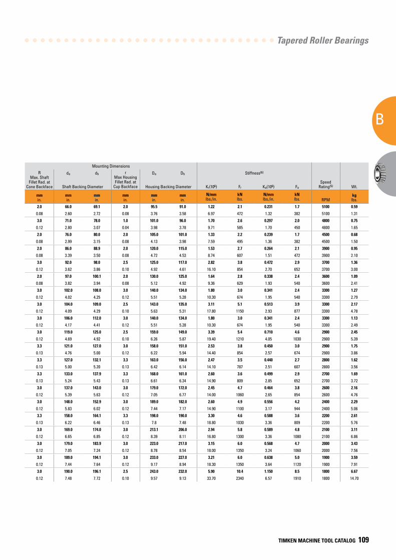
Tapered Roller Bearings
B
TIMKEN MACHINE TOOL CATALOG 109
Mounting Dimensions
d Bore
D O.D.
T Width
Load Ratings
B Cone Width
C Cup Width
a Eff. Center(2)
Inner-Outer Part Number
R Max. Shaft
Fillet Rad. at Cone Backface
da db r Max Housing Fillet Rad. at
Cup Backface
Da Db Stiffness(6)
SpeedRating(5) Wt.
Co Static
C1
Dynamic(3)C90
Dynamic(4) Ca90
Dynamic(4) Shaft Backing Diameter Housing Backing Diameter Kr(106) Fr Ka(106) Fa
mmin.
mmin.
mmin.
kNlbs.
kNlbs.
kNlbs.
kNlbs.
mmin.
mmin.
mmin.
mmin.
mmin.
mmin.
mmin.
mmin.
mmin.
N/mmlbs./in.
kNlbs.
N/mmlbs./in.
kNlbs. RPM
kglbs.
60.000 100.000 21.000 101.0 80.9 21.0 17.0 20.000 15.500 1.3 JP6049-JP6010 2.0 66.0 69.1 2.0 95.5 91.0 1.22 2.1 0.231 1.7 5100 0.59
2.3622 3.9370 0.8268 22700 18200 4720 3820 0.7874 0.6102 0.05 0.08 2.60 2.72 0.08 3.76 3.58 6.97 472 1.32 382 5100 1.31
65.000 105.000 24.000 139.0 100.0 26.0 20.2 23.000 18.500 -0.3 JLM710949C-JLM710910 3.0 71.0 78.0 1.0 101.0 96.0 1.70 2.6 0.297 2.0 4800 0.75
2.5591 4.1339 0.9449 31200 22500 5850 4540 0.9055 0.7283 -0.01 0.12 2.80 3.07 0.04 3.98 3.78 9.71 585 1.70 450 4800 1.65
70.000 110.000 21.000 112.0 84.8 22.0 17.4 20.000 15.500 2.5 JP7049-JP7010 2.0 76.0 80.0 2.0 105.0 101.0 1.33 2.2 0.239 1.7 4500 0.68
2.7559 4.3307 0.8268 25200 19100 4950 3910 0.7874 0.6102 0.10 0.08 2.99 3.15 0.08 4.13 3.98 7.59 495 1.36 382 4500 1.50
80.000 125.000 24.000 141.0 105.0 27.2 21.0 22.500 17.500 2.3 JP8049-JP8010 2.0 86.0 88.9 2.0 120.0 115.0 1.53 2.7 0.264 2.1 3900 0.95
3.1496 4.9213 0.9449 31700 23600 6120 4720 0.8858 0.6890 0.09 0.08 3.39 3.50 0.08 4.72 4.53 8.74 607 1.51 472 3900 2.10
85.000 130.000 30.000 245.0 149.0 38.7 29.4 29.000 24.000 -0.3 JM716649-JM716610 3.0 92.0 98.0 2.5 125.0 117.0 2.82 3.8 0.472 2.9 3700 1.36
3.3465 5.1181 1.1811 55100 33500 8700 6610 1.1417 0.9449 -0.01 0.12 3.62 3.86 0.10 4.92 4.61 16.10 854 2.70 652 3700 3.00
90.000 135.000 24.000 155.0 110.0 28.4 24.0 22.500 17.500 5.6 JP9049-JP9010 2.0 97.0 100.1 2.0 130.0 125.0 1.64 2.8 0.338 2.4 3600 1.09
3.5433 5.3150 0.9449 34800 24700 6390 5400 0.8858 0.6890 0.22 0.08 3.82 3.94 0.08 5.12 4.92 9.36 629 1.93 540 3600 2.41
95.000 145.000 24.000 172.0 116.0 30.1 24.4 22.500 17.500 6.1 JP10044-JP10010 3.0 102.0 108.0 3.0 140.0 134.0 1.80 3.0 0.341 2.4 3300 1.27
3.7402 5.7087 0.9449 38700 26100 6770 5490 0.8858 0.6890 0.24 0.12 4.02 4.25 0.12 5.51 5.28 10.30 674 1.95 540 3300 2.79
95.000 150.000 35.000 317.0 199.0 51.5 39.0 34.000 27.000 -1.5 JM719149-JM719113 3.0 104.0 109.0 2.5 143.0 135.0 3.11 5.1 0.513 3.9 3300 2.17
3.7402 5.9055 1.3780 71300 44700 11600 8770 1.3386 1.0630 -0.06 0.12 4.09 4.29 0.10 5.63 5.31 17.80 1150 2.93 877 3300 4.78
100.000 145.000 24.000 172.0 116.0 30.1 24.4 22.500 17.500 6.1 JP10049-JP10010 3.0 106.0 112.0 3.0 140.0 134.0 1.80 3.0 0.341 2.4 3300 1.13
3.9370 5.7087 0.9449 38700 26100 6770 5490 0.8858 0.6890 0.24 0.12 4.17 4.41 0.12 5.51 5.28 10.30 674 1.95 540 3300 2.49
110.000 165.000 35.000 357.0 210.0 54.5 46.4 35.000 26.500 3.0 JM822049-JM822010 3.0 119.0 125.0 2.5 159.0 149.0 3.39 5.4 0.710 4.6 2900 2.45
4.3307 6.4961 1.3780 80300 47200 12300 10400 1.3780 1.0433 0.12 0.12 4.69 4.92 0.10 6.26 5.87 19.40 1210 4.05 1030 2900 5.39
115.000 165.000 28.000 245.0 148.0 38.3 30.1 27.000 21.000 5.6 JLM722948-JLM722912 3.3 121.0 127.0 3.0 158.0 151.0 2.53 3.8 0.450 3.0 2900 1.75
4.5276 6.4961 1.1024 55100 33300 8610 6770 1.0630 0.8268 0.22 0.13 4.76 5.00 0.12 6.22 5.94 14.40 854 2.57 674 2900 3.86
120.000 170.000 25.400 231.0 134.0 34.8 27.3 25.400 19.050 7.9 JL724348-JL724314 3.3 127.0 132.1 3.3 163.0 156.0 2.47 3.5 0.440 2.7 2800 1.62
4.7244 6.6929 1.0000 51900 30100 7820 6140 1.0000 0.7500 0.31 0.13 5.00 5.20 0.13 6.42 6.14 14.10 787 2.51 607 2800 3.56
125.000 175.000 25.400 246.0 139.0 36.0 29.4 25.400 18.288 9.1 JL725346-JL725316 3.3 133.0 137.9 3.3 168.0 161.0 2.60 3.6 0.499 2.9 2700 1.69
4.9213 6.8898 1.0000 55300 31200 8090 6610 1.0000 0.7200 0.36 0.13 5.24 5.43 0.13 6.61 6.34 14.90 809 2.85 652 2700 3.72
130.000 185.000 29.000 283.0 181.0 47.0 38.1 27.000 21.000 8.9 JP13049-JP13010 3.0 137.0 143.0 3.0 179.0 172.0 2.45 4.7 0.464 3.8 2600 2.16
5.1181 7.2835 1.1417 63600 40700 10600 8570 1.0630 0.8268 0.35 0.12 5.39 5.63 0.12 7.05 6.77 14.00 1060 2.65 854 2600 4.76
140.000 195.000 29.000 304.0 188.0 48.8 42.0 27.000 21.000 11.9 JP14049-JP14010 3.0 148.0 152.9 3.0 189.0 182.0 2.60 4.9 0.556 4.2 2400 2.29
5.5118 7.6772 1.1417 68300 42300 11000 9440 1.0630 0.8268 0.47 0.12 5.83 6.02 0.12 7.44 7.17 14.90 1100 3.17 944 2400 5.06
150.000 205.000 28.575 339.0 179.0 46.5 36.5 28.575 21.438 11.4 JL730646-JL730612 3.3 158.0 164.1 3.3 198.0 190.0 3.30 4.6 0.588 3.6 2200 2.61
5.9055 8.0709 1.1250 76200 40200 10500 8210 1.1250 0.8440 0.45 0.13 6.22 6.46 0.13 7.8 7.48 18.80 1030 3.36 809 2200 5.76
160.000 220.000 32.000 372.0 224.0 58.1 48.4 30.000 23.000 13.0 JP16049-JP16010 3.0 169.0 174.0 3.0 213.1 206.0 2.94 5.8 0.589 4.8 2100 3.11
6.2992 8.6614 1.2598 83600 50400 13100 10900 1.1811 0.9055 0.51 0.12 6.65 6.85 0.12 8.39 8.11 16.80 1300 3.36 1080 2100 6.86
170.000 230.000 32.000 398.0 232.0 60.1 47.5 30.000 23.000 13.0 JP17049-JP17010 3.0 179.0 183.9 3.0 223.0 217.0 3.15 6.0 0.568 4.7 2000 3.43
6.6929 9.0551 1.2598 89500 52200 13500 10700 1.1811 0.9055 0.51 0.12 7.05 7.24 0.12 8.78 8.54 18.00 1350 3.24 1060 2000 7.56
180.000 240.000 32.000 490.0 234.0 60.6 50.3 30.000 23.000 16.0 JP18049-JP18010 3.0 189.0 194.1 3.0 233.0 227.0 3.21 6.0 0.638 5.0 1900 3.59
7.0866 9.4488 1.2598 91900 52600 13600 11300 1.1811 0.9055 0.63 0.12 7.44 7.64 0.12 9.17 8.94 18.30 1350 3.64 1120 1900 7.91
180.000 250.000 47.000 786.0 401.0 104.0 85.5 45.000 37.000 8.9 JM736149-JM736110 3.0 190.0 196.1 2.5 243.0 232.0 5.90 10.4 1.150 8.5 1800 6.67
7.0866 9.8425 1.8504 177000 90200 23400 19200 1.7717 1.4567 0.35 0.12 7.48 7.72 0.10 9.57 9.13 33.70 2340 6.57 1910 1800 14.70
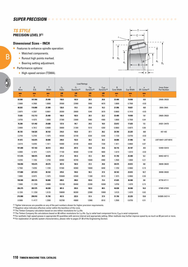
SUPER PRECISION
B
110 TIMKEN MACHINE TOOL CATALOG
TS STYLEPRECISION LEVEL 3(1)
Dimensional Sizes – INCH
• Features to enhance spindle operation:
• Matched components.
• Runout high points marked.
• Bearing setting adjustment.
• Performance options:
• High-speed version (TSMA).
B
T
r
D Db
dad
dbDa
C
R
a
Mounting Dimensions
d Bore
D O.D.
T Width
Load Ratings
B Cone Width
C Cup Width
a Eff. Center(2)
Inner-Outer Part Number
R Max. Shaft
Fillet Rad. at Cone Backface
da dbr
Max Housing Fillet Rad. at
Cup Backface
Da Db Stiffness(6)
SpeedRating(5) Wt.
Co Static
C1
Dynamic(3)C90
Dynamic(4) Ca90
Dynamic(4) Shaft Backing Diameter Housing Backing Diameter Kr(106) Fr Ka(106) Fa
mmin.
mmin.
mmin.
kNlbs.
kNlbs.
kNlbs.
kNlbs.
mmin.
mmin.
mmin.
mmin.
mmin.
mmin.
mmin.
mmin.
mmin.
N/mmlbs./in.
kNlbs.
N/mmlbs./in.
kNlbs.
RPM
kglbs.
63.500 107.950 25.400 158.0 102.0 26.5 20.8 25.400 19.050 -0.8 29585-29520 3.6 71.1 77.0 3.3 103.1 96.0 2.15 2.65 0.385 2.07 4500 0.91
2.5000 4.2500 1.0000 35500 22900 5950 4670 1.0000 0.7500 -0.03 0.14 2.80 3.03 0.13 4.06 3.78 12.30 595 2.20 466 4500 2.01
68.263 110.000 21.999 126.0 91.6 23.8 16.3 21.996 18.821 -0.8 399A-394A 2.3 73.9 78.0 1.3 103.9 101.1 1.53 2.38 0.208 1.63 4600 0.75
2.6875 4.3307 0.8661 28300 20600 5340 3670 0.8660 0.7410 -0.03 0.09 2.91 3.07 0.05 4.09 3.98 8.73 534 1.19 367 4600 1.65
73.025 112.713 25.400 166.0 102.0 26.5 22.2 25.400 19.050 1.0 29685-29620 3.6 80.0 86.1 3.3 109.0 101.1 2.19 2.65 0.440 2.21 4200 0.88
2.8750 4.4375 1.0000 37300 23000 5960 4980 1.0000 0.7500 0.04 0.14 3.15 3.39 0.13 4.29 3.98 12.50 596 2.51 497 4200 1.95
76.200 121.442 24.608 137.0 94.7 24.5 18.9 23.012 17.625 1.5 34301-34478 3.6 83.1 88.9 2.0 116.1 110.0 1.62 2.45 0.278 1.89 4100 0.95
3.0000 4.7812 0.9688 30800 21300 5510 4260 0.9060 0.6875 0.06 0.14 3.27 3.50 0.08 4.57 4.33 9.25 551 1.59 425 4100 2.09
85.725 136.525 30.163 216.0 143.0 37.1 28.2 29.769 22.225 -0.8 497-493 3.6 93.0 99.1 3.3 130.0 121.9 2.31 3.71 0.387 2.82 3700 1.52
3.3750 5.3750 1.1875 48500 32100 8330 6340 1.1720 0.8750 -0.03 0.14 3.66 3.90 0.13 5.12 4.80 13.20 834 2.21 633 3700 3.34
91.973 142.875 30.000 240.0 152.0 39.3 32.2 30.000 21.996 1.8 LM718947-LM718910 3.6 100.1 105.9 3.3 137.9 129.0 2.52 3.93 0.489 3.21 3400 1.63
3.6210 5.6250 1.1811 54000 34100 8830 7230 1.1811 0.8660 0.07 0.14 3.94 4.17 0.13 5.43 5.08 14.40 883 2.79 722 3400 3.60
101.600 157.163 36.513 343.0 207.0 53.8 43.6 36.116 26.187 -0.5 52400-52618 3.6 111.0 117.1 3.3 151.9 142.0 3.31 5.36 0.630 4.35 3100 2.39
4.0000 6.1875 1.4375 77100 46500 12100 9800 1.4219 1.0310 -0.02 0.14 4.37 4.61 0.13 5.98 5.59 18.90 1206 3.60 979 3100 5.28
117.475 180.975 34.925 271.0 181.0 47.2 39.9 31.750 25.400 5.3 68462-68712 3.6 125.0 132.1 3.3 172.0 163.1 2.31 4.69 0.485 3.99 2800 2.75
4.6250 7.1250 1.3750 60900 40700 10600 8980 1.2500 1.0000 0.21 0.14 4.92 5.20 0.13 6.77 6.42 13.20 1055 2.77 897 2800 6.06
146.050 193.675 28.575 407.0 182.0 47.2 29.8 28.575 23.012 4.8 36690-36620 1.5 152.9 154.9 1.5 188.0 182.1 4.55 4.72 0.524 2.97 2300 2.25
5.7500 7.6250 1.1250 91500 40900 10600 6690 1.1250 0.9060 0.19 0.06 6.02 6.10 0.06 7.40 7.17 26.00 1060 2.99 667 2300 4.96
177.800 227.013 30.163 470.0 194.0 50.3 37.9 30.163 23.012 12.7 36990-36920 1.5 185.9 188.0 1.5 221.0 214.1 5.13 5.02 0.842 3.78 1900 2.88
7.0000 8.9375 1.1875 105600 43500 11300 8510 1.1875 0.9060 0.50 0.06 7.32 7.40 0.06 8.70 8.43 29.30 1128 4.81 850 1900 6.35
190.500 282.575 50.800 690.0 398.0 103.0 73.4 47.625 36.500 3.8 87750-87111 3.6 202.9 209.0 3.3 267.0 261.1 4.52 10.31 0.660 7.32 1700 9.48
7.5000 11.1250 2.0000 155100 89400 23200 16500 1.8750 1.4370 0.15 0.14 7.99 8.23 0.13 10.51 10.28 25.80 2318 3.77 1646 1700 20.91
206.375 282.575 46.038 881.0 393.0 102.0 88.5 46.038 36.500 16.0 67985-67920 3.6 218.9 224.0 3.3 275.1 260.1 6.92 10.18 1.520 8.86 1600 8.29
8.1250 11.1250 1.8125 198000 88300 22900 19900 1.8125 1.4370 0.63 0.14 8.62 8.82 0.13 10.83 10.24 39.50 2288 8.68 1992 1600 18.28
215.900 290.010 31.750 457.0 222.0 57.4 37.9 31.750 22.225 13.0 543085-543114 3.6 226.1 231.9 3.3 276.1 272.0 3.92 5.74 0.494 3.78 1600 5.41
8.5000 11.4177 1.2500 102700 49800 12900 8510 1.2500 0.8750 0.51 0.14 8.90 9.13 0.13 10.87 10.71 22.40 1291 2.82 850 1600 11.92
(1) Tighter tolerances are possible on any of the part numbers shown for higher precision requirements.(2) Negative value indicates effective center within the backface of the cone.(3) The Timken Company calculation based on one million revolutions for L10 life.(4) The Timken Company life calculations based on 90 million revolutions for L10 life. C90 is radial load component force; Ca90 is axial component.(5) For synthetic high-speed grease in appropriate fill quantities with service interval and appropriate setting. Other methods may further improve speed by as much as 60 percent or more.(6) For explanation of spindle system characteristics, please refer to pages 27-30 of the Engineering Section.
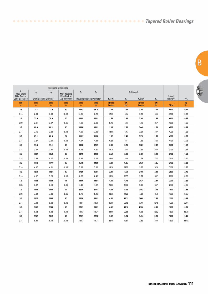
Tapered Roller Bearings
B
TIMKEN MACHINE TOOL CATALOG 111
Mounting Dimensions
d Bore
D O.D.
T Width
Load Ratings
B Cone Width
C Cup Width
a Eff. Center(2)
Inner-Outer Part Number
R Max. Shaft
Fillet Rad. at Cone Backface
da dbr
Max Housing Fillet Rad. at
Cup Backface
Da Db Stiffness(6)
SpeedRating(5) Wt.
Co Static
C1
Dynamic(3)C90
Dynamic(4) Ca90
Dynamic(4) Shaft Backing Diameter Housing Backing Diameter Kr(106) Fr Ka(106) Fa
mmin.
mmin.
mmin.
kNlbs.
kNlbs.
kNlbs.
kNlbs.
mmin.
mmin.
mmin.
mmin.
mmin.
mmin.
mmin.
mmin.
mmin.
N/mmlbs./in.
kNlbs.
N/mmlbs./in.
kNlbs.
RPM
kglbs.
63.500 107.950 25.400 158.0 102.0 26.5 20.8 25.400 19.050 -0.8 29585-29520 3.6 71.1 77.0 3.3 103.1 96.0 2.15 2.65 0.385 2.07 4500 0.91
2.5000 4.2500 1.0000 35500 22900 5950 4670 1.0000 0.7500 -0.03 0.14 2.80 3.03 0.13 4.06 3.78 12.30 595 2.20 466 4500 2.01
68.263 110.000 21.999 126.0 91.6 23.8 16.3 21.996 18.821 -0.8 399A-394A 2.3 73.9 78.0 1.3 103.9 101.1 1.53 2.38 0.208 1.63 4600 0.75
2.6875 4.3307 0.8661 28300 20600 5340 3670 0.8660 0.7410 -0.03 0.09 2.91 3.07 0.05 4.09 3.98 8.73 534 1.19 367 4600 1.65
73.025 112.713 25.400 166.0 102.0 26.5 22.2 25.400 19.050 1.0 29685-29620 3.6 80.0 86.1 3.3 109.0 101.1 2.19 2.65 0.440 2.21 4200 0.88
2.8750 4.4375 1.0000 37300 23000 5960 4980 1.0000 0.7500 0.04 0.14 3.15 3.39 0.13 4.29 3.98 12.50 596 2.51 497 4200 1.95
76.200 121.442 24.608 137.0 94.7 24.5 18.9 23.012 17.625 1.5 34301-34478 3.6 83.1 88.9 2.0 116.1 110.0 1.62 2.45 0.278 1.89 4100 0.95
3.0000 4.7812 0.9688 30800 21300 5510 4260 0.9060 0.6875 0.06 0.14 3.27 3.50 0.08 4.57 4.33 9.25 551 1.59 425 4100 2.09
85.725 136.525 30.163 216.0 143.0 37.1 28.2 29.769 22.225 -0.8 497-493 3.6 93.0 99.1 3.3 130.0 121.9 2.31 3.71 0.387 2.82 3700 1.52
3.3750 5.3750 1.1875 48500 32100 8330 6340 1.1720 0.8750 -0.03 0.14 3.66 3.90 0.13 5.12 4.80 13.20 834 2.21 633 3700 3.34
91.973 142.875 30.000 240.0 152.0 39.3 32.2 30.000 21.996 1.8 LM718947-LM718910 3.6 100.1 105.9 3.3 137.9 129.0 2.52 3.93 0.489 3.21 3400 1.63
3.6210 5.6250 1.1811 54000 34100 8830 7230 1.1811 0.8660 0.07 0.14 3.94 4.17 0.13 5.43 5.08 14.40 883 2.79 722 3400 3.60
101.600 157.163 36.513 343.0 207.0 53.8 43.6 36.116 26.187 -0.5 52400-52618 3.6 111.0 117.1 3.3 151.9 142.0 3.31 5.36 0.630 4.35 3100 2.39
4.0000 6.1875 1.4375 77100 46500 12100 9800 1.4219 1.0310 -0.02 0.14 4.37 4.61 0.13 5.98 5.59 18.90 1206 3.60 979 3100 5.28
117.475 180.975 34.925 271.0 181.0 47.2 39.9 31.750 25.400 5.3 68462-68712 3.6 125.0 132.1 3.3 172.0 163.1 2.31 4.69 0.485 3.99 2800 2.75
4.6250 7.1250 1.3750 60900 40700 10600 8980 1.2500 1.0000 0.21 0.14 4.92 5.20 0.13 6.77 6.42 13.20 1055 2.77 897 2800 6.06
146.050 193.675 28.575 407.0 182.0 47.2 29.8 28.575 23.012 4.8 36690-36620 1.5 152.9 154.9 1.5 188.0 182.1 4.55 4.72 0.524 2.97 2300 2.25
5.7500 7.6250 1.1250 91500 40900 10600 6690 1.1250 0.9060 0.19 0.06 6.02 6.10 0.06 7.40 7.17 26.00 1060 2.99 667 2300 4.96
177.800 227.013 30.163 470.0 194.0 50.3 37.9 30.163 23.012 12.7 36990-36920 1.5 185.9 188.0 1.5 221.0 214.1 5.13 5.02 0.842 3.78 1900 2.88
7.0000 8.9375 1.1875 105600 43500 11300 8510 1.1875 0.9060 0.50 0.06 7.32 7.40 0.06 8.70 8.43 29.30 1128 4.81 850 1900 6.35
190.500 282.575 50.800 690.0 398.0 103.0 73.4 47.625 36.500 3.8 87750-87111 3.6 202.9 209.0 3.3 267.0 261.1 4.52 10.31 0.660 7.32 1700 9.48
7.5000 11.1250 2.0000 155100 89400 23200 16500 1.8750 1.4370 0.15 0.14 7.99 8.23 0.13 10.51 10.28 25.80 2318 3.77 1646 1700 20.91
206.375 282.575 46.038 881.0 393.0 102.0 88.5 46.038 36.500 16.0 67985-67920 3.6 218.9 224.0 3.3 275.1 260.1 6.92 10.18 1.520 8.86 1600 8.29
8.1250 11.1250 1.8125 198000 88300 22900 19900 1.8125 1.4370 0.63 0.14 8.62 8.82 0.13 10.83 10.24 39.50 2288 8.68 1992 1600 18.28
215.900 290.010 31.750 457.0 222.0 57.4 37.9 31.750 22.225 13.0 543085-543114 3.6 226.1 231.9 3.3 276.1 272.0 3.92 5.74 0.494 3.78 1600 5.41
8.5000 11.4177 1.2500 102700 49800 12900 8510 1.2500 0.8750 0.51 0.14 8.90 9.13 0.13 10.87 10.71 22.40 1291 2.82 850 1600 11.92
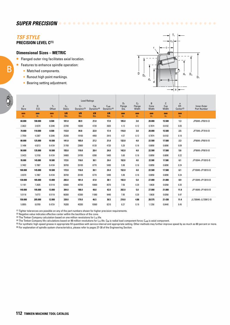
SUPER PRECISION
B
112 TIMKEN MACHINE TOOL CATALOG
TSF STYLEPRECISION LEVEL C(1)
Dimensional Sizes – METRIC
• Flanged outer ring facilitates axial location.
• Features to enhance spindle operation:
• Matched components.
• Runout high point markings.
• Bearing setting adjustment.
a
B
RD1
db Da
c2
T1
cr
D Db
dad
Mounting Dimensions
d Bore
D O.D.
T1 Offset
Load Ratings D1
Flange Dia.
C2 Flange Width
B Cone Width
C Cup
Width
a Eff.
Center(2)Inner-Outer
Part Number
R Max Shaft
Fillet Rad. at Cone Backface
da db r Max Housing Fillet Rad. at
Cup Backface
Da Db Stiffness (6)
SpeedRating(5) Wt.
Co Static
C1
Dynamic(3)C90
Dynamic(4) Ca90
Dynamic(4) Shaft Backing Diameter Housing Backing Diameter Kr(106) Fr Ka(106) Fa
mmin.
mmin.
mmin.
kNlbs.
kNlbs.
kNlbs.
kNlbs.
mmin.
mmin.
mmin.
mmin.
mmin.
mmin.
mmin.
mmin.
mmin.
mmin.
mmin.
N/mmlbs./in.
kNlbs.
N/mmlbs./in.
kNlbs. RPM
kglbs.
60.000 100.000 8.500 101.0 80.9 21.0 17.0 105.0 3.0 20.000 15.500 1.3 JP6049-JP6010-B 2.0 66.0 69.0 2.0 98.0 91.0 1.22 2.1 0.231 1.7 5100 0.61
2.3622 3.9370 0.3346 22700 18200 4720 3820 4.13 0.12 0.7874 0.6102 0.05 0.08 0.08 2.60 2.72 0.08 3.86 3.58 6.97 472 1.32 382 5100 1.34
70.000 110.000 8.500 112.0 84.8 22.0 17.4 116.0 3.0 20.000 15.500 2.5 JP7049-JP7010-B 2.0 2.0 76.0 80.0 2.0 105.5 101.0 1.33 2.2 0.239 1.7 4500 0.69
2.7559 4.3307 0.3346 25200 19100 4950 3910 4.57 0.12 0.7874 0.6102 0.10 0.08 0.08 2.99 3.15 0.08 4.15 3.98 7.59 495 1.36 382 4500 1.52
80.000 125.000 10.500 141.0 105.0 27.2 21.0 132.0 4.0 22.500 17.500 2.3 JP8049-JP8010-B 2.0 2.0 86.0 89.0 2.0 129.0 115.0 1.53 2.7 0.264 2.1 3900 0.95
3.1496 4.9213 0.4134 31700 23600 6120 4720 5.20 0.16 0.8858 0.6890 0.09 0.08 0.08 3.39 3.50 0.08 5.08 4.53 8.74 607 1.51 472 3900 2.09
90.000 135.000 10.500 155.0 110.0 28.4 24.0 142.0 4.0 22.500 17.500 5.6 JP9049-JP9010-B 2.0 2.0 97.0 100.0 2.0 133.0 125.0 1.64 2.8 0.338 2.4 3600 1.09
3.5433 5.3150 0.4134 34800 24700 6390 5400 5.60 0.16 0.8858 0.6890 0.22 0.08 0.08 3.82 3.94 0.08 5.24 4.92 9.36 629 1.93 540 3600 2.40
95.000 145.000 10.500 172.0 116.0 30.1 24.4 152.0 4.0 22.500 17.500 6.1 JP10044-JP10010-B 3.0 3.0 102.0 108.0 3.0 142.0 134.0 1.80 3.0 0.341 2.4 3300 1.32
3.7402 5.7087 0.4134 38700 26100 6770 5490 5.98 0.16 0.8858 0.6890 0.24 0.12 0.12 4.02 4.25 0.12 5.59 5.28 10.28 674 1.95 540 3300 2.91
100.000 145.000 10.500 172.0 116.0 30.1 24.4 152.0 4.0 22.500 17.500 6.1 JP10049-JP10010-B 3.0 3.0 106.0 112.0 3.0 142.0 134.0 1.80 3.0 0.341 2.4 3300 1.13
3.9370 5.7087 0.4134 38700 26100 6770 5490 5.98 0.16 0.8858 0.6890 0.24 0.12 0.12 4.17 4.41 0.12 5.59 5.28 10.28 674 1.95 540 3300 2.49
130.000 185.000 13.000 283.0 181.0 47.0 38.1 192.0 5.0 27.000 21.000 8.9 JP13049-JP13010-B 3.0 3.0 137.0 143.0 3.0 188.0 172.0 2.45 4.7 0.464 3.8 2600 2.20
5.1181 7.2835 0.5118 63600 40700 10600 8570 7.56 0.20 1.0630 0.8268 0.35 0.12 0.12 5.39 5.63 0.12 7.40 6.77 13.99 1057 2.65 854 2600 4.85
140.000 195.000 13.000 304.0 188.0 48.8 42.0 202.0 5.0 27.000 21.000 11.9 JP14049-JP14010-B 3.0 3.0 148.0 153.0 3.0 198.0 182.0 2.60 4.9 0.556 4.2 2400 2.31
5.5118 7.6772 0.5118 68300 42300 11000 9440 7.95 0.20 1.0630 0.8268 0.47 0.12 0.12 5.83 6.02 0.12 7.80 7.17 14.85 1102 3.17 944 2400 5.09
150.000 205.000 12.000 339.0 179.0 46.5 36.5 210.0 4.86 28.575 21.438 11.4 JL730646-JL730612-B 3.3 3.3 158.0 164.0 3.3 200.0 190.0 3.30 4.6 0.588 3.6 2200 2.69
5.9055 8.0709 0.4724 76200 40200 10500 8210 8.27 0.19 1.1250 0.8440 0.45 0.13 0.13 6.22 6.46 0.13 7.87 7.48 18.84 1034 3.36 809 2200 5.93
(1) Tighter tolerances are possible on any of the part numbers shown for higher precision requirements.(2) Negative value indicates effective center within the backface of the cone.(3) The Timken Company calculation based on one million revolutions for L10 life.(4) The Timken Company life calculations based on 90 million revolutions for L10 life. C90 is radial load component force; Ca90 is axial component.(5) For synthetic high-speed grease in appropriate fill quantities with service interval and appropriate setting. Other methods may further improve speed by as much as 60 percent or more.(6) For explanation of spindle system characteristics, please refer to pages 27-30 of the Engineering Section.

Tapered Roller Bearings
B
TIMKEN MACHINE TOOL CATALOG 113
Mounting Dimensions
d Bore
D O.D.
T1 Offset
Load Ratings D1
Flange Dia.
C2 Flange Width
B Cone Width
C Cup
Width
a Eff.
Center(2)Inner-Outer
Part Number
R Max Shaft
Fillet Rad. at Cone Backface
da db r Max Housing Fillet Rad. at
Cup Backface
Da Db Stiffness (6)
SpeedRating(5) Wt.
Co Static
C1
Dynamic(3)C90
Dynamic(4) Ca90
Dynamic(4) Shaft Backing Diameter Housing Backing Diameter Kr(106) Fr Ka(106) Fa
mmin.
mmin.
mmin.
kNlbs.
kNlbs.
kNlbs.
kNlbs.
mmin.
mmin.
mmin.
mmin.
mmin.
mmin.
mmin.
mmin.
mmin.
mmin.
mmin.
N/mmlbs./in.
kNlbs.
N/mmlbs./in.
kNlbs. RPM
kglbs.
60.000 100.000 8.500 101.0 80.9 21.0 17.0 105.0 3.0 20.000 15.500 1.3 JP6049-JP6010-B 2.0 66.0 69.0 2.0 98.0 91.0 1.22 2.1 0.231 1.7 5100 0.61
2.3622 3.9370 0.3346 22700 18200 4720 3820 4.13 0.12 0.7874 0.6102 0.05 0.08 0.08 2.60 2.72 0.08 3.86 3.58 6.97 472 1.32 382 5100 1.34
70.000 110.000 8.500 112.0 84.8 22.0 17.4 116.0 3.0 20.000 15.500 2.5 JP7049-JP7010-B 2.0 2.0 76.0 80.0 2.0 105.5 101.0 1.33 2.2 0.239 1.7 4500 0.69
2.7559 4.3307 0.3346 25200 19100 4950 3910 4.57 0.12 0.7874 0.6102 0.10 0.08 0.08 2.99 3.15 0.08 4.15 3.98 7.59 495 1.36 382 4500 1.52
80.000 125.000 10.500 141.0 105.0 27.2 21.0 132.0 4.0 22.500 17.500 2.3 JP8049-JP8010-B 2.0 2.0 86.0 89.0 2.0 129.0 115.0 1.53 2.7 0.264 2.1 3900 0.95
3.1496 4.9213 0.4134 31700 23600 6120 4720 5.20 0.16 0.8858 0.6890 0.09 0.08 0.08 3.39 3.50 0.08 5.08 4.53 8.74 607 1.51 472 3900 2.09
90.000 135.000 10.500 155.0 110.0 28.4 24.0 142.0 4.0 22.500 17.500 5.6 JP9049-JP9010-B 2.0 2.0 97.0 100.0 2.0 133.0 125.0 1.64 2.8 0.338 2.4 3600 1.09
3.5433 5.3150 0.4134 34800 24700 6390 5400 5.60 0.16 0.8858 0.6890 0.22 0.08 0.08 3.82 3.94 0.08 5.24 4.92 9.36 629 1.93 540 3600 2.40
95.000 145.000 10.500 172.0 116.0 30.1 24.4 152.0 4.0 22.500 17.500 6.1 JP10044-JP10010-B 3.0 3.0 102.0 108.0 3.0 142.0 134.0 1.80 3.0 0.341 2.4 3300 1.32
3.7402 5.7087 0.4134 38700 26100 6770 5490 5.98 0.16 0.8858 0.6890 0.24 0.12 0.12 4.02 4.25 0.12 5.59 5.28 10.28 674 1.95 540 3300 2.91
100.000 145.000 10.500 172.0 116.0 30.1 24.4 152.0 4.0 22.500 17.500 6.1 JP10049-JP10010-B 3.0 3.0 106.0 112.0 3.0 142.0 134.0 1.80 3.0 0.341 2.4 3300 1.13
3.9370 5.7087 0.4134 38700 26100 6770 5490 5.98 0.16 0.8858 0.6890 0.24 0.12 0.12 4.17 4.41 0.12 5.59 5.28 10.28 674 1.95 540 3300 2.49
130.000 185.000 13.000 283.0 181.0 47.0 38.1 192.0 5.0 27.000 21.000 8.9 JP13049-JP13010-B 3.0 3.0 137.0 143.0 3.0 188.0 172.0 2.45 4.7 0.464 3.8 2600 2.20
5.1181 7.2835 0.5118 63600 40700 10600 8570 7.56 0.20 1.0630 0.8268 0.35 0.12 0.12 5.39 5.63 0.12 7.40 6.77 13.99 1057 2.65 854 2600 4.85
140.000 195.000 13.000 304.0 188.0 48.8 42.0 202.0 5.0 27.000 21.000 11.9 JP14049-JP14010-B 3.0 3.0 148.0 153.0 3.0 198.0 182.0 2.60 4.9 0.556 4.2 2400 2.31
5.5118 7.6772 0.5118 68300 42300 11000 9440 7.95 0.20 1.0630 0.8268 0.47 0.12 0.12 5.83 6.02 0.12 7.80 7.17 14.85 1102 3.17 944 2400 5.09
150.000 205.000 12.000 339.0 179.0 46.5 36.5 210.0 4.86 28.575 21.438 11.4 JL730646-JL730612-B 3.3 3.3 158.0 164.0 3.3 200.0 190.0 3.30 4.6 0.588 3.6 2200 2.69
5.9055 8.0709 0.4724 76200 40200 10500 8210 8.27 0.19 1.1250 0.8440 0.45 0.13 0.13 6.22 6.46 0.13 7.87 7.48 18.84 1034 3.36 809 2200 5.93
(1) Tighter tolerances are possible on any of the part numbers shown for higher precision requirements.(2) Negative value indicates effective center within the backface of the cone.(3) The Timken Company calculation based on one million revolutions for L10 life.(4) The Timken Company life calculations based on 90 million revolutions for L10 life. C90 is radial load component force; Ca90 is axial component.(5) For synthetic high-speed grease in appropriate fill quantities with service interval and appropriate setting. Other methods may further improve speed by as much as 60 percent or more.(6) For explanation of spindle system characteristics, please refer to pages 27-30 of the Engineering Section.
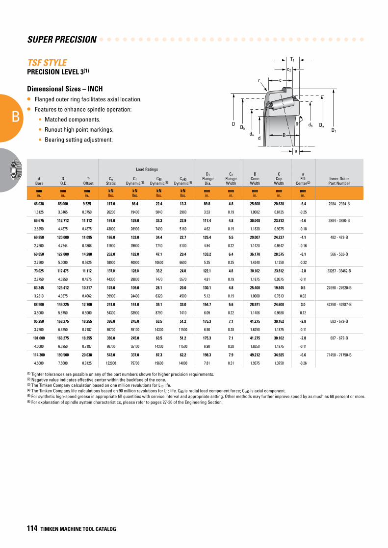
SUPER PRECISION
B
114 TIMKEN MACHINE TOOL CATALOG
TSF STYLEPRECISION LEVEL 3(1)
Dimensional Sizes – INCH
• Flanged outer ring facilitates axial location.
• Features to enhance spindle operation:
• Matched components.
• Runout high point markings.
• Bearing setting adjustment.
a
B
RD1
db Da
c2
T1
cr
D Db
dad
Mounting Dimensions
d Bore
D O.D.
T1 Offset
Load Ratings D1
Flange Dia.
C2 Flange Width
B Cone Width
C Cup
Width
a Eff.
Center(2)Inner-Outer
Part Number
R Max. Shaft
Fillet Rad. at Cone Backface
da db r Max Housing Fillet Rad. at
Cup Backface
Da Db Stiffness (6)
SpeedRating(5) Wt.
Co Static
C1
Dynamic(3)C90
Dynamic(4) Ca90
Dynamic(4) Shaft Backing Diameter Housing Backing Diameter Kr(106) Fr Ka(106) Fa
mmin.
mmin.
mmin.
kNlbs.
kNlbs.
kNlbs.
kNlbs.
mmin.
mmin.
mmin.
mmin.
mmin.
mmin.
mmin.
mmin.
mmin.
mmin.
mmin.
N/mmlbs./in.
kNlbs.
N/mmlbs./in.
kNlbs. RPM
kglbs.
46.038 85.000 9.525 117.0 86.4 22.4 13.3 89.8 4.8 25.608 20.638 -6.4 2984 - 2924-B 3.5 52.0 58.0 1.3 82.0 76.0 1.68 2.2 0.170 1.3 6200 0.65
1.8125 3.3465 0.3750 26200 19400 5040 2980 3.53 0.19 1.0082 0.8125 -0.25 0.08 0.14 2.05 2.28 0.05 3.23 2.99 9.60 504 0.97 298 6200 1.43
66.675 112.712 11.112 191.0 129.0 33.3 22.9 117.4 4.8 30.048 23.812 -4.6 3984 - 3920-B 2.0 3.5 74.0 80.0 3.3 108.0 99.0 2.33 3.3 0.318 2.3 4600 1.18
2.6250 4.4375 0.4375 43000 28900 7490 5160 4.62 0.19 1.1830 0.9375 -0.18 0.08 0.14 2.91 3.15 0.13 4.25 3.90 13.30 749 1.82 516 4600 2.61
69.850 120.000 11.095 186.0 133.0 34.4 22.7 125.4 5.5 29.007 24.237 -4.1 482 - 472-B 2.0 3.5 77.0 83.0 0.8 115.0 108.0 2.08 3.4 0.261 2.3 4300 1.36
2.7500 4.7244 0.4368 41900 29900 7740 5100 4.94 0.22 1.1420 0.9542 -0.16 0.08 0.14 3.03 3.27 0.03 4.53 4.25 11.90 774 1.49 510 4300 2.99
69.850 127.000 14.288 262.0 182.0 47.1 29.4 133.2 6.4 36.170 28.575 -8.1 566 - 563-B 2.0 3.5 78.0 85.0 3.3 121.0 112.0 2.71 4.7 0.303 2.9 4100 1.97
2.7500 5.0000 0.5625 58900 40900 10600 6600 5.25 0.25 1.4240 1.1250 -0.32 0.08 0.14 3.07 3.35 0.13 4.76 4.41 15.50 1060 1.73 660 4100 4.34
73.025 117.475 11.112 197.0 128.0 33.2 24.8 122.1 4.8 30.162 23.812 -2.8 33287 - 33462-B 3.0 3.5 80.0 87.0 3.3 114.0 104.0 2.38 3.3 0.383 2.5 4300 1.25
2.8750 4.6250 0.4375 44300 28800 7470 5570 4.81 0.19 1.1875 0.9375 -0.11 0.12 0.14 3.15 3.43 0.13 4.49 4.09 13.60 747 2.19 557 4300 2.75
83.345 125.412 10.317 178.0 109.0 28.1 20.0 130.1 4.8 25.400 19.845 0.5 27690 - 27620-B 3.0 3.5 90.0 96.0 1.5 123.0 115.0 2.27 2.8 0.332 2.0 3800 1.08
3.2813 4.9375 0.4062 39900 24400 6320 4500 5.12 0.19 1.0000 0.7813 0.02 0.12 0.14 3.54 3.78 0.06 4.84 4.53 12.90 632 1.90 450 3800 2.37
88.900 149.225 12.700 241.0 151.0 39.1 33.0 154.7 5.6 28.971 24.608 3.0 42350 - 42587-B 3.0 3.0 98.0 104.0 3.3 152.0 134.0 2.52 3.9 0.518 3.3 3300 2.13
3.5000 5.8750 0.5000 54300 33900 8790 7410 6.09 0.22 1.1406 0.9688 0.12 0.12 0.12 3.86 4.09 0.13 5.98 5.28 14.40 879 2.96 741 3300 4.70
95.250 168.275 18.255 386.0 245.0 63.5 51.2 175.3 7.1 41.275 30.162 -2.8 683 - 672-B 3.0 3.5 106.0 113.0 3.3 160.0 149.0 3.39 6.4 0.635 5.1 3000 3.79
3.7500 6.6250 0.7187 86700 55100 14300 11500 6.90 0.28 1.6250 1.1875 -0.11 0.12 0.14 4.17 4.45 0.13 6.30 5.87 19.30 1430 3.62 1150 3000 8.36
101.600 168.275 18.255 386.0 245.0 63.5 51.2 175.3 7.1 41.275 30.162 -2.8 687 - 672-B 3.0 3.5 112.0 118.0 3.3 160.0 149.0 3.39 6.4 0.635 5.1 3000 3.47
4.0000 6.6250 0.7187 86700 55100 14300 11500 6.90 0.28 1.6250 1.1875 -0.11 0.12 0.14 4.41 4.65 0.13 6.30 5.87 19.30 1430 3.62 1150 3000 7.66
114.300 190.500 20.638 543.0 337.0 87.3 62.2 198.3 7.9 49.212 34.925 -6.6 71450 - 71750-B 3.3 3.5 125.0 132.0 3.3 181.0 171.0 4.28 8.7 0.627 6.2 2700 5.31
4.5000 7.5000 0.8125 122000 75700 19600 14000 7.81 0.31 1.9375 1.3750 -0.26 0.13 0.14 4.92 5.20 0.13 7.13 6.73 24.50 1960 3.58 1400 2700 11.70
(1) Tighter tolerances are possible on any of the part numbers shown for higher precision requirements.(2) Negative value indicates effective center within the backface of the cone.(3) The Timken Company calculation based on one million revolutions for L10 life.(4) The Timken Company life calculations based on 90 million revolutions for L10 life. C90 is radial load component force; Ca90 is axial component.(5) For synthetic high-speed grease in appropriate fill quantities with service interval and appropriate setting. Other methods may further improve speed by as much as 60 percent or more.(6) For explanation of spindle system characteristics, please refer to pages 27-30 of the Engineering Section.
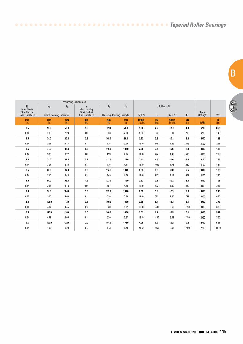
Tapered Roller Bearings
B
TIMKEN MACHINE TOOL CATALOG 115
Mounting Dimensions
d Bore
D O.D.
T1 Offset
Load Ratings D1
Flange Dia.
C2 Flange Width
B Cone Width
C Cup
Width
a Eff.
Center(2)Inner-Outer
Part Number
R Max. Shaft
Fillet Rad. at Cone Backface
da db r Max Housing Fillet Rad. at
Cup Backface
Da Db Stiffness (6)
SpeedRating(5) Wt.
Co Static
C1
Dynamic(3)C90
Dynamic(4) Ca90
Dynamic(4) Shaft Backing Diameter Housing Backing Diameter Kr(106) Fr Ka(106) Fa
mmin.
mmin.
mmin.
kNlbs.
kNlbs.
kNlbs.
kNlbs.
mmin.
mmin.
mmin.
mmin.
mmin.
mmin.
mmin.
mmin.
mmin.
mmin.
mmin.
N/mmlbs./in.
kNlbs.
N/mmlbs./in.
kNlbs. RPM
kglbs.
46.038 85.000 9.525 117.0 86.4 22.4 13.3 89.8 4.8 25.608 20.638 -6.4 2984 - 2924-B 3.5 52.0 58.0 1.3 82.0 76.0 1.68 2.2 0.170 1.3 6200 0.65
1.8125 3.3465 0.3750 26200 19400 5040 2980 3.53 0.19 1.0082 0.8125 -0.25 0.08 0.14 2.05 2.28 0.05 3.23 2.99 9.60 504 0.97 298 6200 1.43
66.675 112.712 11.112 191.0 129.0 33.3 22.9 117.4 4.8 30.048 23.812 -4.6 3984 - 3920-B 2.0 3.5 74.0 80.0 3.3 108.0 99.0 2.33 3.3 0.318 2.3 4600 1.18
2.6250 4.4375 0.4375 43000 28900 7490 5160 4.62 0.19 1.1830 0.9375 -0.18 0.08 0.14 2.91 3.15 0.13 4.25 3.90 13.30 749 1.82 516 4600 2.61
69.850 120.000 11.095 186.0 133.0 34.4 22.7 125.4 5.5 29.007 24.237 -4.1 482 - 472-B 2.0 3.5 77.0 83.0 0.8 115.0 108.0 2.08 3.4 0.261 2.3 4300 1.36
2.7500 4.7244 0.4368 41900 29900 7740 5100 4.94 0.22 1.1420 0.9542 -0.16 0.08 0.14 3.03 3.27 0.03 4.53 4.25 11.90 774 1.49 510 4300 2.99
69.850 127.000 14.288 262.0 182.0 47.1 29.4 133.2 6.4 36.170 28.575 -8.1 566 - 563-B 2.0 3.5 78.0 85.0 3.3 121.0 112.0 2.71 4.7 0.303 2.9 4100 1.97
2.7500 5.0000 0.5625 58900 40900 10600 6600 5.25 0.25 1.4240 1.1250 -0.32 0.08 0.14 3.07 3.35 0.13 4.76 4.41 15.50 1060 1.73 660 4100 4.34
73.025 117.475 11.112 197.0 128.0 33.2 24.8 122.1 4.8 30.162 23.812 -2.8 33287 - 33462-B 3.0 3.5 80.0 87.0 3.3 114.0 104.0 2.38 3.3 0.383 2.5 4300 1.25
2.8750 4.6250 0.4375 44300 28800 7470 5570 4.81 0.19 1.1875 0.9375 -0.11 0.12 0.14 3.15 3.43 0.13 4.49 4.09 13.60 747 2.19 557 4300 2.75
83.345 125.412 10.317 178.0 109.0 28.1 20.0 130.1 4.8 25.400 19.845 0.5 27690 - 27620-B 3.0 3.5 90.0 96.0 1.5 123.0 115.0 2.27 2.8 0.332 2.0 3800 1.08
3.2813 4.9375 0.4062 39900 24400 6320 4500 5.12 0.19 1.0000 0.7813 0.02 0.12 0.14 3.54 3.78 0.06 4.84 4.53 12.90 632 1.90 450 3800 2.37
88.900 149.225 12.700 241.0 151.0 39.1 33.0 154.7 5.6 28.971 24.608 3.0 42350 - 42587-B 3.0 3.0 98.0 104.0 3.3 152.0 134.0 2.52 3.9 0.518 3.3 3300 2.13
3.5000 5.8750 0.5000 54300 33900 8790 7410 6.09 0.22 1.1406 0.9688 0.12 0.12 0.12 3.86 4.09 0.13 5.98 5.28 14.40 879 2.96 741 3300 4.70
95.250 168.275 18.255 386.0 245.0 63.5 51.2 175.3 7.1 41.275 30.162 -2.8 683 - 672-B 3.0 3.5 106.0 113.0 3.3 160.0 149.0 3.39 6.4 0.635 5.1 3000 3.79
3.7500 6.6250 0.7187 86700 55100 14300 11500 6.90 0.28 1.6250 1.1875 -0.11 0.12 0.14 4.17 4.45 0.13 6.30 5.87 19.30 1430 3.62 1150 3000 8.36
101.600 168.275 18.255 386.0 245.0 63.5 51.2 175.3 7.1 41.275 30.162 -2.8 687 - 672-B 3.0 3.5 112.0 118.0 3.3 160.0 149.0 3.39 6.4 0.635 5.1 3000 3.47
4.0000 6.6250 0.7187 86700 55100 14300 11500 6.90 0.28 1.6250 1.1875 -0.11 0.12 0.14 4.41 4.65 0.13 6.30 5.87 19.30 1430 3.62 1150 3000 7.66
114.300 190.500 20.638 543.0 337.0 87.3 62.2 198.3 7.9 49.212 34.925 -6.6 71450 - 71750-B 3.3 3.5 125.0 132.0 3.3 181.0 171.0 4.28 8.7 0.627 6.2 2700 5.31
4.5000 7.5000 0.8125 122000 75700 19600 14000 7.81 0.31 1.9375 1.3750 -0.26 0.13 0.14 4.92 5.20 0.13 7.13 6.73 24.50 1960 3.58 1400 2700 11.70
(1) Tighter tolerances are possible on any of the part numbers shown for higher precision requirements.(2) Negative value indicates effective center within the backface of the cone.(3) The Timken Company calculation based on one million revolutions for L10 life.(4) The Timken Company life calculations based on 90 million revolutions for L10 life. C90 is radial load component force; Ca90 is axial component.(5) For synthetic high-speed grease in appropriate fill quantities with service interval and appropriate setting. Other methods may further improve speed by as much as 60 percent or more.(6) For explanation of spindle system characteristics, please refer to pages 27-30 of the Engineering Section.
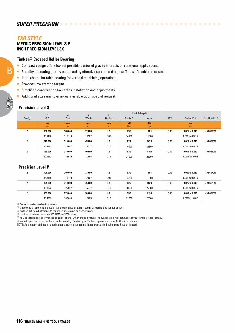
SUPER PRECISION
B
116 TIMKEN MACHINE TOOL CATALOG
TXR STYLEMETRIC PRECISION LEVEL S,P INCH PRECISION LEVEL 3.0
Timken® Crossed Roller Bearing
• Compact design offers lowest possible center of gravity in precision rotational applications.
• Stability of bearing greatly enhanced by effective spread and high stiffness of double roller set.
• Ideal choice for table bearing for vertical machining operations.
• Provides low starting torque.
• Simplified construction facilitates installation and adjustments.
• Additional sizes and tolerances available upon special request.
Precision Level S
DO.D.
dBore
TWidth
RRadius
Load Ratings(4)
Config. Radial(1) Axial K(2) Preload(5.3) Part Number(6)
mm in.
mm in.
mm in.
mm in.
kN lbs.
kN lbs.
mm in.
2 400.000 300.000 37.000 1.5 63.0 80.1 0.45 0.025 to 0.040 JXR637050
15.7480 11.8110 1.4567 0.06 14200 18000 0.001 to 0.0015
2 425.000 310.000 45.000 2.5 82.2 102.0 0.46 0.025 to 0.040 JXR652050
16.7323 12.2047 1.7717 0.10 18500 22900 0.001 to 0.0015
2 495.000 370.000 50.000 3.0 93.6 119.0 0.45 0.040 to 0.050 JXR699050
19.4882 14.5669 1.9685 0.12 21000 26800 0.0015 to 0.002
(1) Two-row radial load rating shown.(2) K-factor is a ratio of radial load rating to axial load rating – see Engineering Section for usage.(3) Preload set by adjustments to top inner ring clamping spacer plate.(4) Load calculations based on 500 RPM for 3000 hours.(5) Values listed apply to lower speed applications. Other preload values are available on request. Contact your Timken representative.(6) Not all types and sizes are listed in this catalog. Contact your Timken representative for further information.NOTE: Application of these preload values assumes suggested fitting practice in Engineering Section is used.
Precision Level P2 400.000 300.000 37.000 1.5 63.0 80.1 0.45 0.025 to 0.040 JXR637050
15.7480 11.8110 1.4567 0.06 14200 18000 0.001 to 0.0015
2 425.000 310.000 45.000 2.5 82.2 102.0 0.46 0.025 to 0.040 JXR652050
16.7323 12.2047 1.7717 0.10 18500 22900 0.001 to 0.0015
2 495.000 370.000 50.000 3.0 93.6 119.0 0.45 0.040 to 0.050 JXR699050
19.4882 14.5669 1.9685 0.12 21000 26800 0.0015 to 0.002
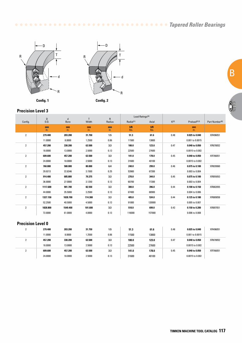
Tapered Roller Bearings
B
TIMKEN MACHINE TOOL CATALOG 117
R
D
d
R
RR
T
d
T
D
Config. 1 Config. 2
Precision Level 3
DO.D.
dBore
TWidth
RRadius
Load Ratings(4)
Config. Radial(1) Axial K(2) Preload(5.3) Part Number(6)
mm in.
mm in.
mm in.
mm in.
kN lbs.
kN lbs.
mm in.
2 279.400 203.200 31.750 1.5 51.3 61.6 0.48 0.025 to 0.040 XR496051
11.0000 8.0000 1.2500 0.06 11500 13800 0.001 to 0.0015
2 457.200 330.200 63.500 3.3 100.0 123.0 0.47 0.040 to 0.050 XR678052
18.0000 13.0000 2.5000 0.13 22500 27600 0.0015 to 0.002
2 609.600 457.200 63.500 3.3 141.0 178.0 0.45 0.040 to 0.050 XR766051
24.0000 18.0000 2.5000 0.13 31600 40100 0.0015 to 0.002
2 760.000 580.000 80.000 6.4 240.0 299.0 0.46 0.075 to 0.100 XR820060
29.9213 22.8346 3.1500 0.25 53900 67200 0.003 to 0.004
2 914.400 685.800 79.375 3.3 270.0 344.0 0.45 0.075 to 0.100 XR855053
36.0000 27.0000 3.1250 0.13 60700 77200 0.003 to 0.004
2 1117.600 901.700 82.550 3.3 300.0 396.0 0.44 0.100 to 0.150 XR882055
44.0000 35.5000 3.2500 0.13 67400 88900 0.004 to 0.006
2 1327.150 1028.700 114.300 3.3 405.0 534.0 0.44 0.125 to 0.180 XR889058
52.2500 40.5000 4.5000 0.13 91000 120000 0.005 to 0.007
2 1828.800 1549.400 101.600 3.3 518.0 699.0 0.43 0.150 to 0.200 XR897051
72.0000 61.0000 4.0000 0.13 116000 157000 0.006 to 0.008
Precision Level 02 279.400 203.200 31.750 1.5 51.3 61.6 0.48 0.025 to 0.040 XR496051
11.0000 8.0000 1.2500 0.06 11500 13800 0.001 to 0.0015
2 457.200 330.200 63.500 3.3 100.0 123.0 0.47 0.040 to 0.050 XR678052
18.0000 13.0000 2.5000 0.13 22500 27600 0.0015 to 0.002
2 609.600 457.200 63.500 3.3 141.0 178.0 0.45 0.040 to 0.050 XR766051
24.0000 18.0000 2.5000 0.13 31600 40100 0.0015 to 0.002
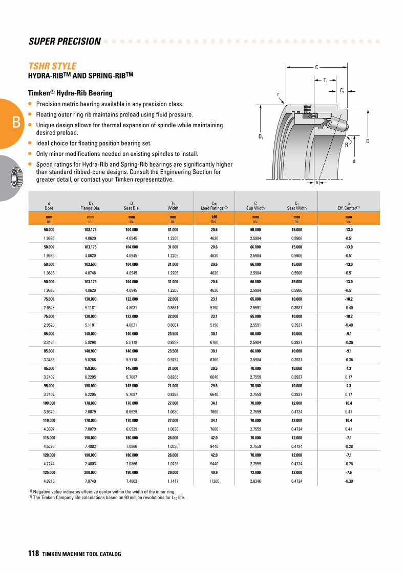
SUPER PRECISION
B
118 TIMKEN MACHINE TOOL CATALOG
(1) Negative value indicates effective center within the width of the inner ring.(2) The Timken Company life calculations based on 90 million revolutions for L10 life.
TSHR STYLEHYDRA-RIBTM AND SPRING-RIBTM
Timken® Hydra-Rib Bearing
• Precision metric bearing available in any precision class.
• Floating outer ring rib maintains preload using fluid pressure.
• Unique design allows for thermal expansion of spindle while maintaining desired preload.
• Ideal choice for floating position bearing set.
• Only minor modifications needed on existing spindles to install.
• Speed ratings for Hydra-Rib and Spring-Rib bearings are significantly higher than standard ribbed-cone designs. Consult the Engineering Section for greater detail, or contact your Timken representative.
T1
D1D
C1
d
a
R
r
C
Mounting Dimensions Stiffness
dBore
D1Flange Dia.
DSeat Dia.
T1Width
C90 Load Ratings (2)
CCup Width
C1Seat Width
aEff. Center(1)
Hydra-Rib Part Number
RShaft Radius
ShaftShoulder Dia.
rHousing Radius Kr (106) Fr Ka (106) Fa
mmin.
mmin.
mmin.
mmin.
kNlbs.
mmin.
mmin.
mmin.
mmin.
mmin.
mmin.
N/mmlbs./in.
kNlbs.
N/mmlbs./in.
kNlbs.
50.000 103.175 104.000 31.000 20.6 66.000 15.000 -13.0 JP5049PH-JP5017HR 3.0 61.0 1.0 1.18 2.06 0.126 1.25
1.9685 4.0620 4.0945 1.2205 4630 2.5984 0.5906 -0.51 0.12 2.40 0.04 6.77 463 0.721 282
50.000 103.175 104.000 31.000 20.6 66.000 15.000 -13.0 JP5049PH-JP5020HR 3.0 61.0 1.0 1.18 2.06 0.126 1.25
1.9685 4.0620 4.0945 1.2205 4630 2.5984 0.5906 -0.51 0.12 2.40 0.04 6.77 463 0.721 282
50.000 103.500 104.000 31.000 20.6 66.000 15.000 -13.0 JP5049P-JP5019HR 3.0 61.0 1.0 1.18 2.06 0.126 1.25
1.9685 4.0748 4.0945 1.2205 4630 2.5984 0.5906 -0.51 0.12 2.40 0.04 6.77 463 0.721 282
50.000 103.175 104.000 31.000 20.6 66.000 15.000 -13.0 JP5049P-JP5020HR 3.0 61.0 1.0 1.18 2.06 0.126 1.25
1.9685 4.0620 4.0945 1.2205 4630 2.5984 0.5906 -0.51 0.12 2.40 0.04 6.77 463 0.721 282
75.000 130.000 122.000 22.000 23.1 65.000 10.000 -10.2 JP7548P-JP7520HR 3.0 85.0 2.0 1.43 2.31 0.177 1.52
2.9528 5.1181 4.8031 0.8661 5190 2.5591 0.3937 -0.40 0.12 3.35 0.08 8.14 519 1.01 341
75.000 130.000 122.000 22.000 23.1 65.000 10.000 -10.2 JP7549P-JP7519HR 3.0 85.0 2.0 1.43 2.31 0.177 1.52
2.9528 5.1181 4.8031 0.8661 5190 2.5591 0.3937 -0.40 0.12 3.35 0.08 8.14 519 1.01 341
85.000 148.000 140.000 23.500 30.1 66.000 10.000 -9.1 JP8548-JP8518HR 3.0 96.0 2.0 1.77 3.01 0.212 1.93
3.3465 5.8268 5.5118 0.9252 6760 2.5984 0.3937 -0.36 0.12 3.78 0.08 10.1 676 1.21 435
85.000 148.000 140.000 23.500 30.1 66.000 10.000 -9.1 JP8549P-JP8519HR 3.0 96.0 2.0 1.77 3.01 0.212 1.93
3.3465 5.8268 5.5118 0.9252 6760 2.5984 0.3937 -0.36 0.12 3.78 0.08 10.1 676 1.21 435
95.000 158.000 145.000 21.000 29.5 70.000 10.000 4.3 JP10048-JP10019HR 3.0 107.0 1.5 1.76 2.95 0.222 1.95
3.7402 6.2205 5.7087 0.8268 6640 2.7559 0.3937 0.17 0.12 4.21 0.06 10.0 664 1.27 439
95.000 158.000 145.000 21.000 29.5 70.000 10.000 4.3 JP10048-JP10019HRA 3.0 107.0 1.5 1.76 2.95 0.222 1.95
3.7402 6.2205 5.7087 0.8268 6640 2.7559 0.3937 0.17 0.12 4.21 0.06 10.0 664 1.27 439
100.000 178.000 170.000 27.000 34.1 70.000 12.000 10.4 JP11035-JP11019HR 3.0 114.0 1.0 2.05 3.41 0.224 2.10
3.9370 7.0079 6.6929 1.0630 7660 2.7559 0.4724 0.41 0.12 4.49 0.04 11.7 766 1.28 471
110.000 178.000 170.000 27.000 34.1 70.000 12.000 10.4 JP11048-JP11019HR 3.0 122.0 1.0 2.05 3.41 0.224 2.10
4.3307 7.0079 6.6929 1.0630 7660 2.7559 0.4724 0.41 0.12 4.80 0.04 11.7 766 1.28 471
115.000 190.000 180.000 26.000 42.0 70.000 12.000 -7.1 JP12043P-JP12019HR 3.0 128.0 1.0 2.41 4.20 0.310 2.80
4.5276 7.4803 7.0866 1.0236 9440 2.7559 0.4724 -0.28 0.12 5.04 0.04 13.8 944 1.77 630
120.000 190.000 180.000 26.000 42.0 70.000 12.000 -7.1 JP12049P-JP12019HR 3.0 132.0 1.0 2.41 4.20 0.310 2.80
4.7244 7.4803 7.0866 1.0236 9440 2.7559 0.4724 -0.28 0.12 5.20 0.04 13.8 944 1.77 630
125.000 200.000 190.000 29.000 49.9 72.000 12.000 -7.6 JP13043P-JP13016HR 3.0 138.0 1.0 2.78 4.99 0.200 2.50
4.9213 7.8740 7.4803 1.1417 11200 2.8346 0.4724 -0.30 0.12 5.43 0.04 15.9 1120 1.14 561
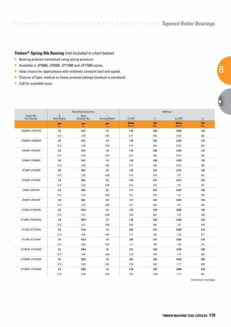
Tapered Roller Bearings
B
TIMKEN MACHINE TOOL CATALOG 119
Mounting Dimensions Stiffness
dBore
D1Flange Dia.
DSeat Dia.
T1Width
C90 Load Ratings (2)
CCup Width
C1Seat Width
aEff. Center(1)
Hydra-Rib Part Number
RShaft Radius
ShaftShoulder Dia.
rHousing Radius Kr (106) Fr Ka (106) Fa
mmin.
mmin.
mmin.
mmin.
kNlbs.
mmin.
mmin.
mmin.
mmin.
mmin.
mmin.
N/mmlbs./in.
kNlbs.
N/mmlbs./in.
kNlbs.
50.000 103.175 104.000 31.000 20.6 66.000 15.000 -13.0 JP5049PH-JP5017HR 3.0 61.0 1.0 1.18 2.06 0.126 1.25
1.9685 4.0620 4.0945 1.2205 4630 2.5984 0.5906 -0.51 0.12 2.40 0.04 6.77 463 0.721 282
50.000 103.175 104.000 31.000 20.6 66.000 15.000 -13.0 JP5049PH-JP5020HR 3.0 61.0 1.0 1.18 2.06 0.126 1.25
1.9685 4.0620 4.0945 1.2205 4630 2.5984 0.5906 -0.51 0.12 2.40 0.04 6.77 463 0.721 282
50.000 103.500 104.000 31.000 20.6 66.000 15.000 -13.0 JP5049P-JP5019HR 3.0 61.0 1.0 1.18 2.06 0.126 1.25
1.9685 4.0748 4.0945 1.2205 4630 2.5984 0.5906 -0.51 0.12 2.40 0.04 6.77 463 0.721 282
50.000 103.175 104.000 31.000 20.6 66.000 15.000 -13.0 JP5049P-JP5020HR 3.0 61.0 1.0 1.18 2.06 0.126 1.25
1.9685 4.0620 4.0945 1.2205 4630 2.5984 0.5906 -0.51 0.12 2.40 0.04 6.77 463 0.721 282
75.000 130.000 122.000 22.000 23.1 65.000 10.000 -10.2 JP7548P-JP7520HR 3.0 85.0 2.0 1.43 2.31 0.177 1.52
2.9528 5.1181 4.8031 0.8661 5190 2.5591 0.3937 -0.40 0.12 3.35 0.08 8.14 519 1.01 341
75.000 130.000 122.000 22.000 23.1 65.000 10.000 -10.2 JP7549P-JP7519HR 3.0 85.0 2.0 1.43 2.31 0.177 1.52
2.9528 5.1181 4.8031 0.8661 5190 2.5591 0.3937 -0.40 0.12 3.35 0.08 8.14 519 1.01 341
85.000 148.000 140.000 23.500 30.1 66.000 10.000 -9.1 JP8548-JP8518HR 3.0 96.0 2.0 1.77 3.01 0.212 1.93
3.3465 5.8268 5.5118 0.9252 6760 2.5984 0.3937 -0.36 0.12 3.78 0.08 10.1 676 1.21 435
85.000 148.000 140.000 23.500 30.1 66.000 10.000 -9.1 JP8549P-JP8519HR 3.0 96.0 2.0 1.77 3.01 0.212 1.93
3.3465 5.8268 5.5118 0.9252 6760 2.5984 0.3937 -0.36 0.12 3.78 0.08 10.1 676 1.21 435
95.000 158.000 145.000 21.000 29.5 70.000 10.000 4.3 JP10048-JP10019HR 3.0 107.0 1.5 1.76 2.95 0.222 1.95
3.7402 6.2205 5.7087 0.8268 6640 2.7559 0.3937 0.17 0.12 4.21 0.06 10.0 664 1.27 439
95.000 158.000 145.000 21.000 29.5 70.000 10.000 4.3 JP10048-JP10019HRA 3.0 107.0 1.5 1.76 2.95 0.222 1.95
3.7402 6.2205 5.7087 0.8268 6640 2.7559 0.3937 0.17 0.12 4.21 0.06 10.0 664 1.27 439
100.000 178.000 170.000 27.000 34.1 70.000 12.000 10.4 JP11035-JP11019HR 3.0 114.0 1.0 2.05 3.41 0.224 2.10
3.9370 7.0079 6.6929 1.0630 7660 2.7559 0.4724 0.41 0.12 4.49 0.04 11.7 766 1.28 471
110.000 178.000 170.000 27.000 34.1 70.000 12.000 10.4 JP11048-JP11019HR 3.0 122.0 1.0 2.05 3.41 0.224 2.10
4.3307 7.0079 6.6929 1.0630 7660 2.7559 0.4724 0.41 0.12 4.80 0.04 11.7 766 1.28 471
115.000 190.000 180.000 26.000 42.0 70.000 12.000 -7.1 JP12043P-JP12019HR 3.0 128.0 1.0 2.41 4.20 0.310 2.80
4.5276 7.4803 7.0866 1.0236 9440 2.7559 0.4724 -0.28 0.12 5.04 0.04 13.8 944 1.77 630
120.000 190.000 180.000 26.000 42.0 70.000 12.000 -7.1 JP12049P-JP12019HR 3.0 132.0 1.0 2.41 4.20 0.310 2.80
4.7244 7.4803 7.0866 1.0236 9440 2.7559 0.4724 -0.28 0.12 5.20 0.04 13.8 944 1.77 630
125.000 200.000 190.000 29.000 49.9 72.000 12.000 -7.6 JP13043P-JP13016HR 3.0 138.0 1.0 2.78 4.99 0.200 2.50
4.9213 7.8740 7.4803 1.1417 11200 2.8346 0.4724 -0.30 0.12 5.43 0.04 15.9 1120 1.14 561
Continued on next page.
Timken® Spring-Rib Bearing (not included in chart below)
• Bearing preload maintained using spring pressure.
• Available in JP5000, JP8500, JP11000 and JP17000 series.
• Ideal choice for applications with relatively constant load and speed.
• Choices of light, medium or heavy preload settings (medium is standard).
• Call for available sizes.
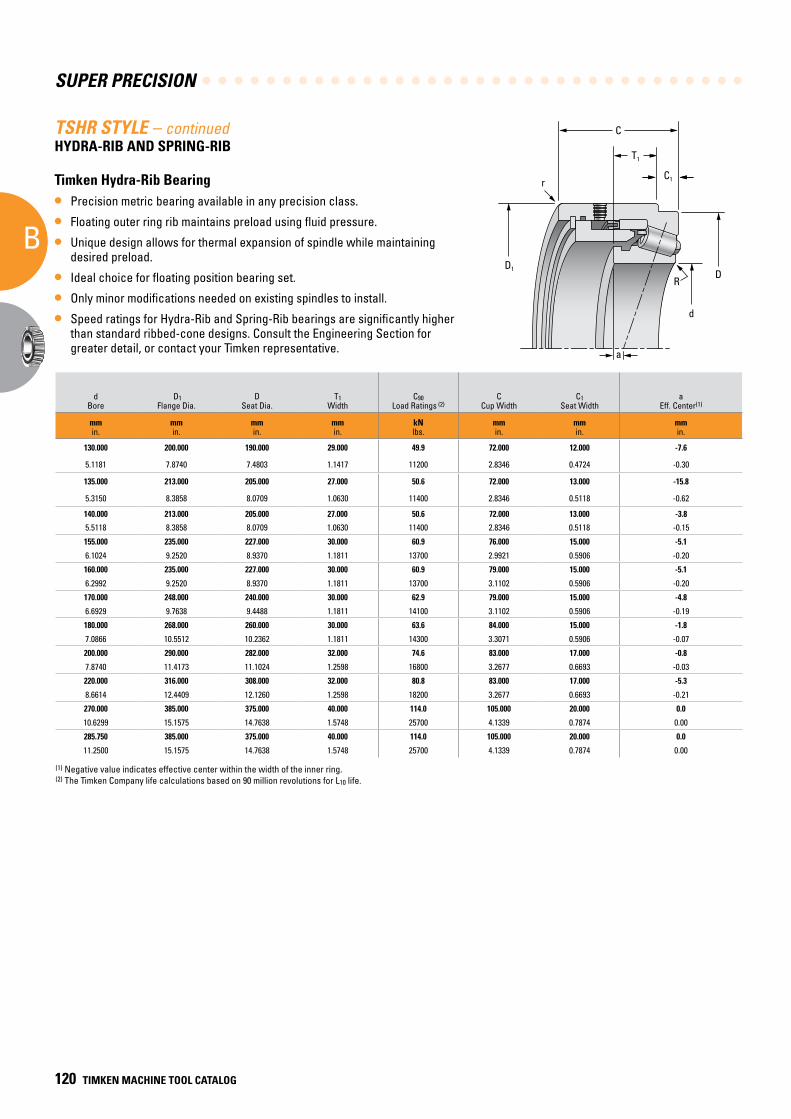
SUPER PRECISION
B
120 TIMKEN MACHINE TOOL CATALOG
T1
D1D
C1
d
a
R
r
CTSHR STYLE – continuedHYDRA-RIB AND SPRING-RIB
Timken Hydra-Rib Bearing
• Precision metric bearing available in any precision class.
• Floating outer ring rib maintains preload using fluid pressure.
• Unique design allows for thermal expansion of spindle while maintaining desired preload.
• Ideal choice for floating position bearing set.
• Only minor modifications needed on existing spindles to install.
• Speed ratings for Hydra-Rib and Spring-Rib bearings are significantly higher than standard ribbed-cone designs. Consult the Engineering Section for greater detail, or contact your Timken representative.
Mounting Dimensions Stiffness
dBore
D1Flange Dia.
DSeat Dia.
T1Width
C90 Load Ratings (2)
CCup Width
C1Seat Width
aEff. Center(1)
Hydra-Rib Part Number
RShaft Radius
ShaftShoulder Dia.
rHousing Radius Kr (106) Fr Ka (106) Fa
mmin.
mmin.
mmin.
mmin.
kNlbs.
mmin.
mmin.
mmin.
mmin.
mmin.
mmin.
N/mmlbs./in.
kNlbs.
N/mmlbs./in.
kNlbs.
130.000 200.000 190.000 29.000 49.9 72.000 12.000 -7.6 JP13049P-JP13016HR 3.0 138.0 1.0 2.78 4.99 0.200 2.50
5.1181 7.8740 7.4803 1.1417 11200 2.8346 0.4724 -0.30 0.12 5.43 0.04 15.9 1120 1.14 561
135.000 213.000 205.000 27.000 50.6 72.000 13.000 -15.8 JP14043P-JP14019HR 3.0 148.0 1.0 2.75 5.06 0.406 3.62
5.3150 8.3858 8.0709 1.0630 11400 2.8346 0.5118 -0.62 0.12 5.83 0.04 15.7 1140 2.32 813
140.000 213.000 205.000 27.000 50.6 72.000 13.000 -3.8 JP14049P-JP14019HR 3.0 152.0 1.0 2.75 5.06 0.406 3.62
5.5118 8.3858 8.0709 1.0630 11400 2.8346 0.5118 -0.15 0.12 5.98 0.04 15.7 1140 2.32 813
155.000 235.000 227.000 30.000 60.9 76.000 15.000 -5.1 JP16043P-JP16019HR 3.0 169.0 1.0 3.16 6.09 0.441 4.24
6.1024 9.2520 8.9370 1.1811 13700 2.9921 0.5906 -0.20 0.12 6.65 0.04 18.0 1370 2.52 953
160.000 235.000 227.000 30.000 60.9 79.000 15.000 -5.1 JP16049P-JP16019HR 3.0 172.0 1.0 3.16 6.09 0.441 4.24
6.2992 9.2520 8.9370 1.1811 13700 3.1102 0.5906 -0.20 0.12 6.77 0.04 18.0 1370 2.52 953
170.000 248.000 240.000 30.000 62.9 79.000 15.000 -4.8 JP17049P-JP17019HR 3.0 182.0 1.0 3.36 6.29 0.432 4.19
6.6929 9.7638 9.4488 1.1811 14100 3.1102 0.5906 -0.19 0.12 7.17 0.04 19.2 1410 2.47 943
180.000 268.000 260.000 30.000 63.6 84.000 15.000 -1.8 JP18049P-JP18019HR 3.0 193.0 1.0 3.44 6.36 0.495 4.49
7.0866 10.5512 10.2362 1.1811 14300 3.3071 0.5906 -0.07 0.12 7.60 0.04 19.6 1430 2.83 1010
200.000 290.000 282.000 32.000 74.6 83.000 17.000 -0.8 JP20049P-JP20019HR 3.0 213.0 1.0 3.47 7.46 0.471 5.12
7.8740 11.4173 11.1024 1.2598 16800 3.2677 0.6693 -0.03 0.12 8.39 0.04 19.8 1680 2.69 1150
220.000 316.000 308.000 32.000 80.8 83.000 17.000 -5.3 JP22049E-JP22019HR 3.0 233.0 1.0 3.93 8.08 0.644 6.09
8.6614 12.4409 12.1260 1.2598 18200 3.2677 0.6693 -0.21 0.12 9.17 0.04 22.4 1820 3.68 1370
270.000 385.000 375.000 40.000 114.0 105.000 20.000 0.0 JL555235-JL55512HR 4.0 293.0 4.0 6.19 11.40 0.666 6.98
10.6299 15.1575 14.7638 1.5748 25700 4.1339 0.7874 0.00 0.16 11.54 0.16 35.4 2570 3.81 1570
285.750 385.000 375.000 40.000 114.0 105.000 20.000 0.0 JL555239-JL55512HR 4.0 293.0 4.0 6.19 11.40 0.666 6.98
11.2500 15.1575 14.7638 1.5748 25700 4.1339 0.7874 0.00 0.16 11.54 0.16 35.4 2570 3.81 1570
(1) Negative value indicates effective center within the width of the inner ring.(2) The Timken Company life calculations based on 90 million revolutions for L10 life.
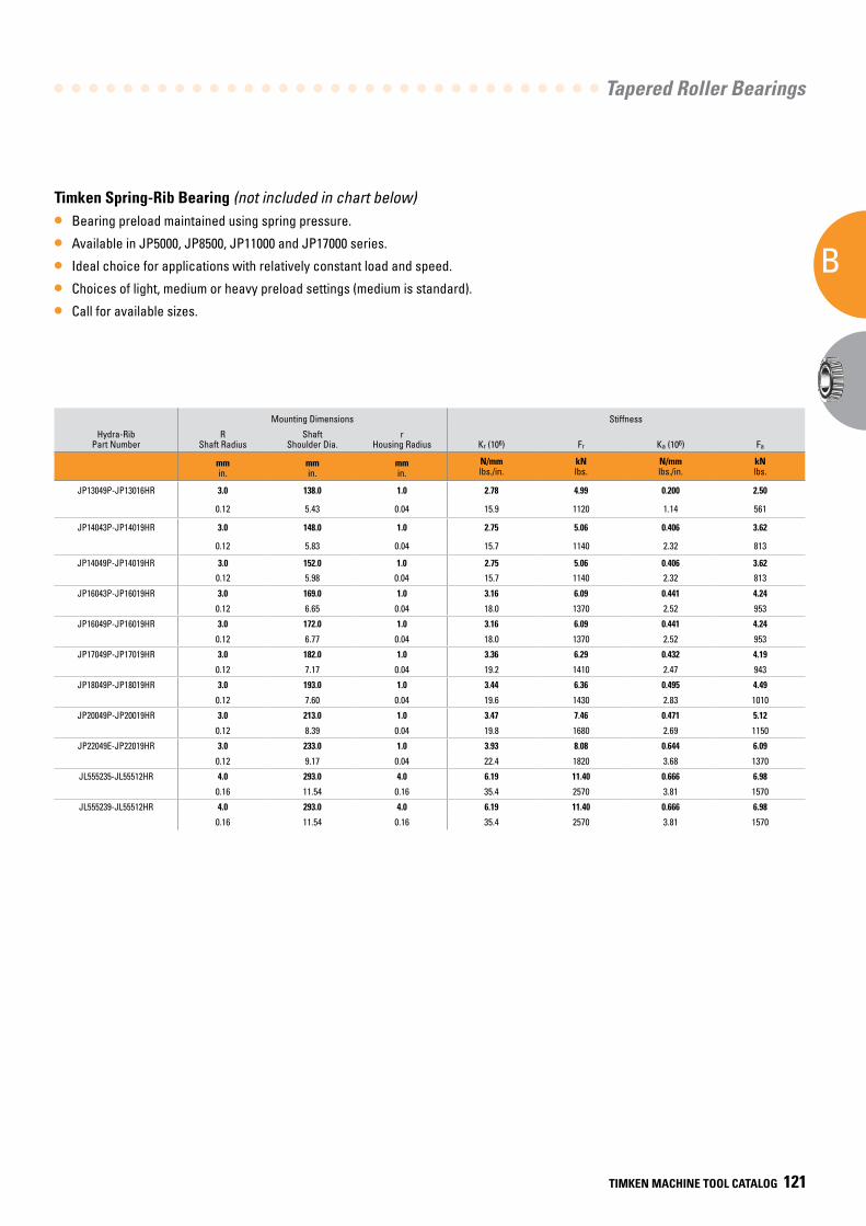
Tapered Roller Bearings
B
TIMKEN MACHINE TOOL CATALOG 121
Mounting Dimensions Stiffness
dBore
D1Flange Dia.
DSeat Dia.
T1Width
C90 Load Ratings (2)
CCup Width
C1Seat Width
aEff. Center(1)
Hydra-Rib Part Number
RShaft Radius
ShaftShoulder Dia.
rHousing Radius Kr (106) Fr Ka (106) Fa
mmin.
mmin.
mmin.
mmin.
kNlbs.
mmin.
mmin.
mmin.
mmin.
mmin.
mmin.
N/mmlbs./in.
kNlbs.
N/mmlbs./in.
kNlbs.
130.000 200.000 190.000 29.000 49.9 72.000 12.000 -7.6 JP13049P-JP13016HR 3.0 138.0 1.0 2.78 4.99 0.200 2.50
5.1181 7.8740 7.4803 1.1417 11200 2.8346 0.4724 -0.30 0.12 5.43 0.04 15.9 1120 1.14 561
135.000 213.000 205.000 27.000 50.6 72.000 13.000 -15.8 JP14043P-JP14019HR 3.0 148.0 1.0 2.75 5.06 0.406 3.62
5.3150 8.3858 8.0709 1.0630 11400 2.8346 0.5118 -0.62 0.12 5.83 0.04 15.7 1140 2.32 813
140.000 213.000 205.000 27.000 50.6 72.000 13.000 -3.8 JP14049P-JP14019HR 3.0 152.0 1.0 2.75 5.06 0.406 3.62
5.5118 8.3858 8.0709 1.0630 11400 2.8346 0.5118 -0.15 0.12 5.98 0.04 15.7 1140 2.32 813
155.000 235.000 227.000 30.000 60.9 76.000 15.000 -5.1 JP16043P-JP16019HR 3.0 169.0 1.0 3.16 6.09 0.441 4.24
6.1024 9.2520 8.9370 1.1811 13700 2.9921 0.5906 -0.20 0.12 6.65 0.04 18.0 1370 2.52 953
160.000 235.000 227.000 30.000 60.9 79.000 15.000 -5.1 JP16049P-JP16019HR 3.0 172.0 1.0 3.16 6.09 0.441 4.24
6.2992 9.2520 8.9370 1.1811 13700 3.1102 0.5906 -0.20 0.12 6.77 0.04 18.0 1370 2.52 953
170.000 248.000 240.000 30.000 62.9 79.000 15.000 -4.8 JP17049P-JP17019HR 3.0 182.0 1.0 3.36 6.29 0.432 4.19
6.6929 9.7638 9.4488 1.1811 14100 3.1102 0.5906 -0.19 0.12 7.17 0.04 19.2 1410 2.47 943
180.000 268.000 260.000 30.000 63.6 84.000 15.000 -1.8 JP18049P-JP18019HR 3.0 193.0 1.0 3.44 6.36 0.495 4.49
7.0866 10.5512 10.2362 1.1811 14300 3.3071 0.5906 -0.07 0.12 7.60 0.04 19.6 1430 2.83 1010
200.000 290.000 282.000 32.000 74.6 83.000 17.000 -0.8 JP20049P-JP20019HR 3.0 213.0 1.0 3.47 7.46 0.471 5.12
7.8740 11.4173 11.1024 1.2598 16800 3.2677 0.6693 -0.03 0.12 8.39 0.04 19.8 1680 2.69 1150
220.000 316.000 308.000 32.000 80.8 83.000 17.000 -5.3 JP22049E-JP22019HR 3.0 233.0 1.0 3.93 8.08 0.644 6.09
8.6614 12.4409 12.1260 1.2598 18200 3.2677 0.6693 -0.21 0.12 9.17 0.04 22.4 1820 3.68 1370
270.000 385.000 375.000 40.000 114.0 105.000 20.000 0.0 JL555235-JL55512HR 4.0 293.0 4.0 6.19 11.40 0.666 6.98
10.6299 15.1575 14.7638 1.5748 25700 4.1339 0.7874 0.00 0.16 11.54 0.16 35.4 2570 3.81 1570
285.750 385.000 375.000 40.000 114.0 105.000 20.000 0.0 JL555239-JL55512HR 4.0 293.0 4.0 6.19 11.40 0.666 6.98
11.2500 15.1575 14.7638 1.5748 25700 4.1339 0.7874 0.00 0.16 11.54 0.16 35.4 2570 3.81 1570
(1) Negative value indicates effective center within the width of the inner ring.(2) The Timken Company life calculations based on 90 million revolutions for L10 life.
Timken Spring-Rib Bearing (not included in chart below)
• Bearing preload maintained using spring pressure.
• Available in JP5000, JP8500, JP11000 and JP17000 series.
• Ideal choice for applications with relatively constant load and speed.
• Choices of light, medium or heavy preload settings (medium is standard).
• Call for available sizes.
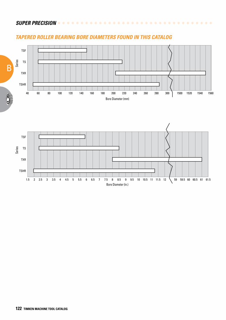
SUPER PRECISION
B
122 TIMKEN MACHINE TOOL CATALOG
TAPERED ROLLER BEARING BORE DIAMETERS FOUND IN THIS CATALOGTapered Bearing Bore Diameters Found In This Catalog
Bore Diameter (in.)
Serie
s
1.5 2 2.5 3 3.5 4 4.5 5 5.5 6 6.5 7 7.5 8 8.5 9 9.5 10 10.5 11 11.5 12 59 59.5 60 60.5 61 61.5
TSF
TS
TXR
TSHR
Bore Diameter (mm)
Serie
s
40 60 80 100 120 140 160 180 200 220 240 260 280 300
TSF
TS
TXR
TSHR
1500 1520 1540 1560
Bore Diameter (mm)
Serie
sSe
ries
Bore Diameter (in.)
TIMKEN MACHINE TOOL CATALOG 127
CBALL BEARIN
GS
C BALL BEARINGS
Part Numbering Systems . . . . . . . . . . . . . . . . . . . . . . . . . . . . . 125
Introduction . . . . . . . . . . . . . . . . . . . . . . . . . . . . . . . . . . . . . . . . 130
Optimized Grades of Precision . . . . . . . . . . . . . . . . . . . . . . . 130
Bearing Types . . . . . . . . . . . . . . . . . . . . . . . . . . . . . . . . . . . . . . 130
Applications . . . . . . . . . . . . . . . . . . . . . . . . . . . . . . . . . . . . . . . 133
Spindle Bearings . . . . . . . . . . . . . . . . . . . . . . . . . . . . . . . . . . . 138
Ball Screw Support Bearings . . . . . . . . . . . . . . . . . . . . . . . . 188
Ex-Cell-O Spindle Bearings . . . . . . . . . . . . . . . . . . . . . . . . . . 202
CC
SUPER PRECISION
C
124 TIMKEN MACHINE TOOL CATALOG124 TIMKEN MACHINE TOOL CATALOG
BALL
BEARINGS
C
Super Precision Ball Bearings
Page
SPINDLE BEARINGS
Ultra-Light 2(3)MM9300WI (71900C(E)-...-P4S) . . . . . . . . . . . . 138
Ultra-Light 2(3)MMV9300HX (HX71900C(E)-...-P4S) . . . . . . . 146
Extra-Light 2(3)MM9100WI (7000C(E)-...-P4S) . . . . . . . . . . . . 154
Extra-Light 2(3)MMV9100HX (HX7000C(E)-...-P4S) . . . . . . . . 162
Ultra-Light MM9100K (6000-...-P4S) . . . . . . . . . . . . . . . . . . . . 170
Light 2(3)MM200WI (7200C(E)-...-P4S) . . . . . . . . . . . . . . . . . . . 172
Light MM200K (6200-...-P4S) . . . . . . . . . . . . . . . . . . . . . . . . . . 180
Medium 2(3)MM300WI (7300C(E)-...-P4S) . . . . . . . . . . . . . . . . 182
Medium MM300K (6300-...-P4S) . . . . . . . . . . . . . . . . . . . . . . . . 186
BALL SCREW SUPPORT BEARINGS
Ball Screw Support Series . . . . . . . . . . . . . . . . . . . . . . . . . . . . 188
BSBU D . . . . . . . . . . . . . . . . . . . . . . . . . . . . . . . . . . . . . . . . . . . . 194
BSBU Q . . . . . . . . . . . . . . . . . . . . . . . . . . . . . . . . . . . . . . . . . . . . 195
BSPB D . . . . . . . . . . . . . . . . . . . . . . . . . . . . . . . . . . . . . . . . . . . . 196
BSPB Q . . . . . . . . . . . . . . . . . . . . . . . . . . . . . . . . . . . . . . . . . . . . 197
MMF Series . . . . . . . . . . . . . . . . . . . . . . . . . . . . . . . . . . . . . . . . 198
MMN Series . . . . . . . . . . . . . . . . . . . . . . . . . . . . . . . . . . . . . . . . 200
Ex-Cell-O Spindle Bearings . . . . . . . . . . . . . . . . . . . . . . . . . . . . 202
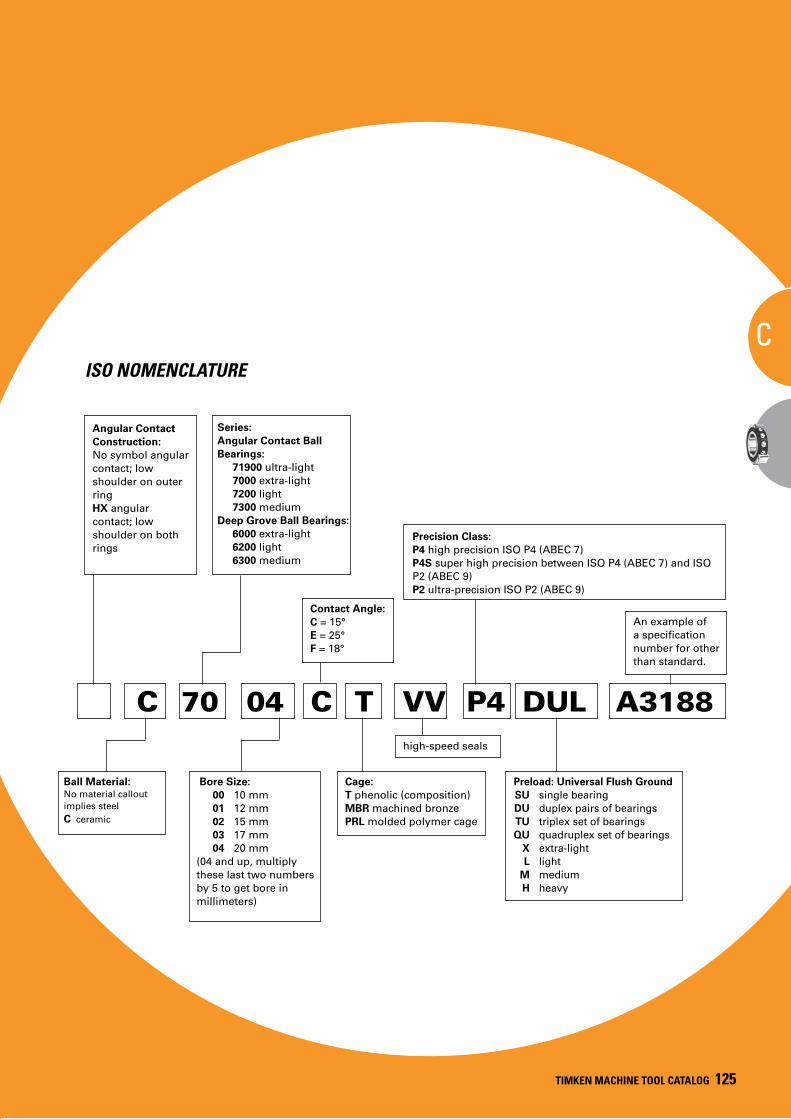
Ball Bearings
C
TIMKEN MACHINE TOOL CATALOG 125
ISO NOMENCLATURE
Ball Material:No material callout implies steelC ceramic
Bore Size: 00 10 mm 01 12 mm 02 15 mm 03 17 mm 04 20 mm(04 and up, multiply these last two numbers by 5 to get bore in millimeters)
C 70 04 C T VV P4 DUL A3188
Precision Class:P4 high precision ISO P4 (ABEC 7)P4S super high precision between ISO P4 (ABEC 7) and ISO P2 (ABEC 9)P2 ultra-precision ISO P2 (ABEC 9)
Preload: Universal Flush Ground SU single bearing DU duplex pairs of bearings TU triplex set of bearings QU quadruplex set of bearings X extra-light L light M medium H heavy
An example of a specification number for other than standard.
Cage:T phenolic (composition)MBR machined bronzePRL molded polymer cage
Contact Angle:C = 15°E = 25°F = 18°
high-speed seals
Angular Contact Construction:No symbol angular contact; low shoulder on outer ringHX angular contact; low shoulder on both rings
Series:Angular Contact Ball Bearings:
71900 ultra-light7000 extra-light7200 light7300 medium
Deep Grove Ball Bearings:6000 extra-light6200 light6300 medium
TIMKEN MACHINE TOOL CATALOG 125
C
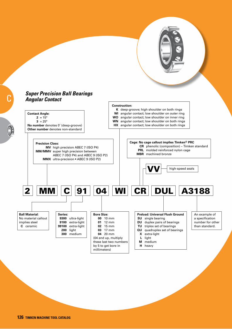
SUPER PRECISION
C
126 TIMKEN MACHINE TOOL CATALOG126 TIMKEN MACHINE TOOL CATALOG
CSuper Precision Ball Bearings
Angular Contact
Ball Material:No material callout implies steel C ceramic
Series: 9300 ultra-light 9100 extra-light 99100 extra-light 200 light 300 medium
2 MM C 91 04 WI CR DUL A3188
Construction: K deep-groove; high shoulder on both rings WI angular contact; low shoulder on outer ring WO angular contact; low shoulder on inner ring WN angular contact; low shoulder on both rings HX angular contact; low shoulder on both rings
Precision Class: MV high precision ABEC 7 (ISO P4) MM/MMV super high precision between ABEC 7 (ISO P4) and ABEC 9 (ISO P2) MMX ultra-precision • ABEC 9 (ISO P2)
Cage: No cage callout implies Timken® PRC CR phenolic (composition) – Timken standard PRL molded reinforced nylon cage
MBR machined bronze
Preload: Universal Flush Ground SU single bearing DU duplex pairs of bearings TU triplex set of bearings QU quadruplex set of bearings X extra-light L light M medium H heavy
An example of a specification number for other than standard.
Bore Size: 00 10 mm 01 12 mm 02 15 mm 03 17 mm 04 20 mm(04 and up, multiply these last two numbers by 5 to get bore in millimeters)
VV high-speed seals
Contact Angle: 2 = 15° 3 = 25°
No number denotes 0˚ (deep-groove)Other number denotes non-standard
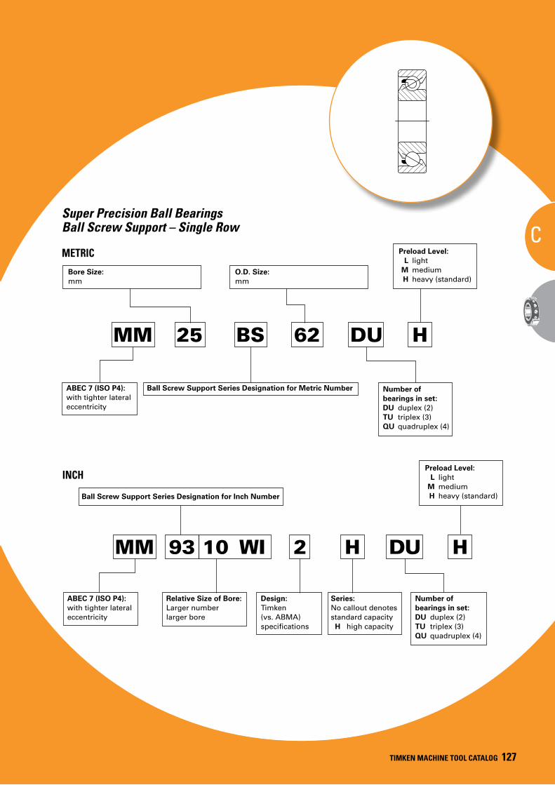
TIMKEN MACHINE TOOL CATALOG 127
TIMKEN MACHINE TOOL CATALOG 127
C
MM 25 BS 62 DU H
Preload Level: L light M medium H heavy (standard)
Bore Size:mm
O.D. Size:mm
Ball Screw Support Series Designation for Metric NumberABEC 7 (ISO P4):with tighter lateraleccentricity
Number ofbearings in set:DU duplex (2) TU triplex (3)QU quadruplex (4)
WIMM 93 10 2 H DU H
Ball Screw Support Series Designation for Inch Number
ABEC 7 (ISO P4):with tighter lateraleccentricity
Relative Size of Bore:Larger numberlarger bore
Design:Timken (vs. ABMA) specifications
Series:No callout denotes standard capacity H high capacity
Number ofbearings in set:DU duplex (2) TU triplex (3)QU quadruplex (4)
INCH
ADDA
C
Preload Level: L light M medium H heavy (standard)
Super Precision Ball Bearings Ball Screw Support – Single Row
METRIC
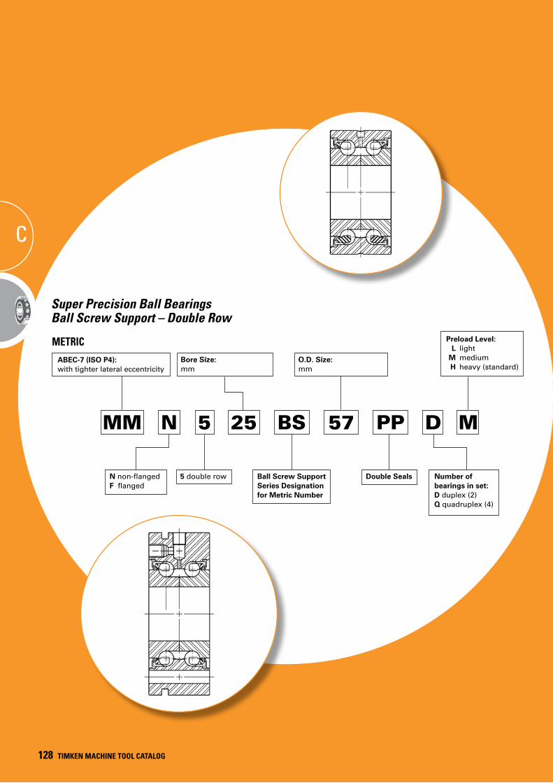
128 TIMKEN MACHINE TOOL CATALOG128 TIMKEN MACHINE TOOL CATALOG
C
Super Precision Ball Bearings Ball Screw Support – Double Row
MM 25 57
ABEC-7 (ISO P4):with tighter lateral eccentricity
O.D. Size:mm
METRIC
Number ofbearings in set:D duplex (2) Q quadruplex (4)
BS
Ball Screw Support Series Designation for Metric Number
PP D
Preload Level: L light M medium H heavy (standard)
M
Bore Size:mm
N
N non-flanged F flanged
5
5 double row Double Seals
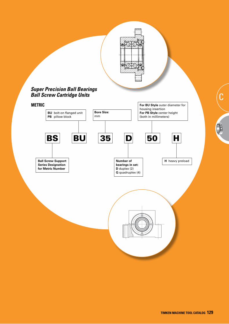
TIMKEN MACHINE TOOL CATALOG 129
TIMKEN MACHINE TOOL CATALOG 129
Super Precision Ball Bearings Ball Screw Cartridge Units
METRIC
BS
Ball Screw Support Series Designation for Metric Number
35
Bore Size:mm
BU
BU bolt-on flanged unit PB pillow block
50
For BU Style outer diameter for housing insertionFor PB Style center height (both in millimeters)
Number ofbearings in set:D duplex (2) Q quadruplex (4)
D H
H heavy preload
C
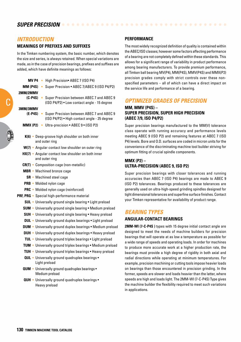
SUPER PRECISION
C
130 TIMKEN MACHINE TOOL CATALOG
INTRODUCTIONMEANINGS OF PREFIXES AND SUFFIXES
In the Timken numbering system, the basic number, which denotes the size and series, is always retained. When special variations are made, as in the case of precision bearings, prefixes and suffixes are added, which have definite meanings as follows:
MV P4 • High Precision• ABEC 7 (ISO P4)
MM (P4S) • Super Precision • ABEC 7/ABEC 9 (ISO P4/P2)
2MM/2MMV (C-P4S) • Super Precision between ABEC 7 and ABEC 9
(ISO P4/P2) • Low contact angle - 15 degree
3MM/3MMV (E-P4S) • Super Precision between ABEC 7 and ABEC 9
(ISO P4/P2) • High contact angle - 25 degree
MMX (P2) • Ultra-precision • ABEC 9 • (ISO P2)
K(6) • Deep-groove high shoulder on both inner and outer ring
W(7) • Angular contact low shoulder on outer ring
HX(7) • Angular contact low shoulder on both inner and outer ring
CR(T) • Composition cage (non-metallic)
MBR • Machined bronze cage
SR • Machined steel cage
PRB • Molded nylon cage
PRC • Molded nylon cage (reinforced)
PRF, PRG • Special high-performance material
SUL • Universally ground single bearing • Light preload
SUM • Universally ground single bearing • Medium preload
SUH • Universally ground single bearing • Heavy preload
DUL • Universally ground duplex bearings • Light preload
DUM • Universally ground duplex bearings • Medium preload
DUH • Universally ground duplex bearings • Heavy preload
TUL • Universally ground triplex bearings • Light preload
TUM • Universally ground triplex bearings • Medium preload
TUH • Universally ground triplex bearings • Heavy preload
QUL • Universally ground quadruplex bearings • Light preload
QUM • Universally ground quadruplex bearings • Medium preload
QUH • Universally ground quadruplex bearings • Heavy preload
PERFORMANCE
The most widely recognized definition of quality is contained within the ABEC/ISO classes; however some factors affecting performance of a bearing are not completely defined within these standards. This allows for a significant range of variability in product performance among bearing manufacturers. To provide premium performance, all Timken ball bearing MV(P4), MM(P4S), MMV(P4S) and MMX(P2) precision grades comply with strict controls over these non-specified parameters – all of which can have a direct impact on the service life and performance of a bearing.
OPTIMIZED GRADES OF PRECISIONMM, MMV (P4S) – SUPER PRECISION, SUPER HIGH PRECISION (ABEC 7/9, ISO P4/P2)
Super precision bearings manufactured to the MM(V) tolerance class operate with running accuracy and performance levels meeting ABEC 9 (ISO P2) and remaining features at ABEC 7 (ISO P4) levels. Bore and O.D. surfaces are coded in micron units for the convenience of the discriminating machine tool builder striving for optimum fitting of crucial spindle components.
MMX (P2) – ULTRA-PRECISION (ABEC 9, ISO P2)
Super precision bearings with closer tolerances and running accuracies than ABEC 7 (ISO P4) bearings are made to ABEC 9 (ISO P2) tolerances. Bearings produced to these tolerances are generally used on ultra-high-speed grinding spindles designed for tight dimensional tolerances and superfine surface finishes. Contact your Timken representative for availability of product range.
BEARING TYPESANGULAR-CONTACT BEARINGS
2MM-WI (7-C-P4S ) types with 15 degree initial contact angle are designed to meet the needs of machine builders for precision bearings that will operate at as low a temperature as possible for a wide range of speeds and operating loads. In order for machines to produce more accurate work at a higher production rate, the bearings must provide a high degree of rigidity in both axial and radial directions while operating at minimum temperatures. For example, precision machining or cutting tools impose heavier loads on bearings than those encountered in precision grinding. In the former, speeds are slower and loads heavier than the latter, where speeds are high and loads light. The 2MM-WI (7-C-P4S) Type gives the machine builder the flexibility required to meet such variations in applications.
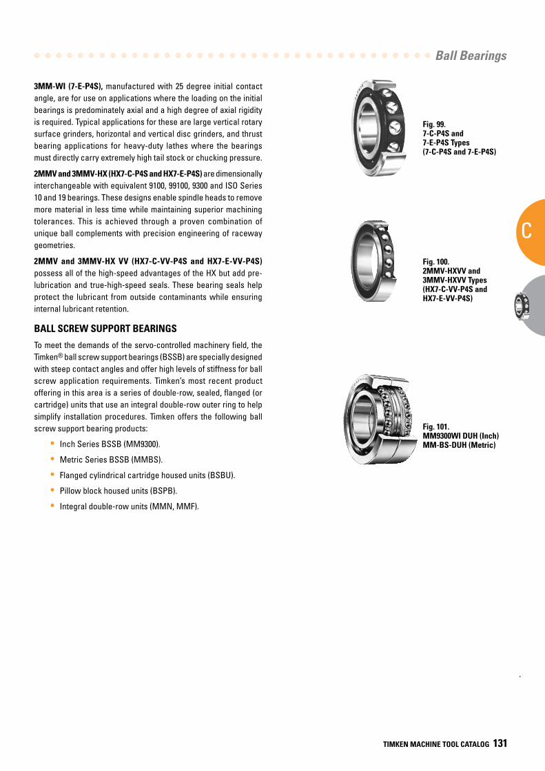
Ball Bearings
C
TIMKEN MACHINE TOOL CATALOG 131
Fig. 99. 7-C-P4S and 7-E-P4S Types(7-C-P4S and 7-E-P4S)
Fig. 100. 2MMV-HXVV and 3MMV-HXVV Types(HX7-C-VV-P4S and HX7-E-VV-P4S)
Fig. 101. MM9300WI DUH (Inch)MM-BS-DUH (Metric)
3MM-WI (7-E-P4S), manufactured with 25 degree initial contact angle, are for use on applications where the loading on the initial bearings is predominately axial and a high degree of axial rigidity is required. Typical applications for these are large vertical rotary surface grinders, horizontal and vertical disc grinders, and thrust bearing applications for heavy-duty lathes where the bearings must directly carry extremely high tail stock or chucking pressure.
2MMV and 3MMV-HX (HX7-C-P4S and HX7-E-P4S) are dimensionally interchangeable with equivalent 9100, 99100, 9300 and ISO Series 10 and 19 bearings. These designs enable spindle heads to remove more material in less time while maintaining superior machining tolerances. This is achieved through a proven combination of unique ball complements with precision engineering of raceway geometries.
2MMV and 3MMV-HX VV (HX7-C-VV-P4S and HX7-E-VV-P4S) possess all of the high-speed advantages of the HX but add pre-lubrication and true-high-speed seals. These bearing seals help protect the lubricant from outside contaminants while ensuring internal lubricant retention.
BALL SCREW SUPPORT BEARINGS
To meet the demands of the servo-controlled machinery field, the Timken® ball screw support bearings (BSSB) are specially designed with steep contact angles and offer high levels of stiffness for ball screw application requirements. Timken’s most recent product offering in this area is a series of double-row, sealed, flanged (or cartridge) units that use an integral double-row outer ring to help simplify installation procedures. Timken offers the following ball screw support bearing products:
• Inch Series BSSB (MM9300).
• Metric Series BSSB (MMBS).
• Flanged cylindrical cartridge housed units (BSBU).
• Pillow block housed units (BSPB).
• Integral double-row units (MMN, MMF).
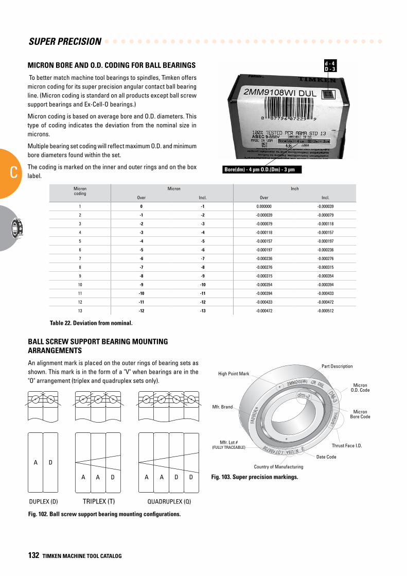
SUPER PRECISION
C
132 TIMKEN MACHINE TOOL CATALOG
MICRON BORE AND O.D. CODING FOR BALL BEARINGS
To better match machine tool bearings to spindles, Timken offers micron coding for its super precision angular contact ball bearing line. (Micron coding is standard on all products except ball screw support bearings and Ex-Cell-O bearings.)
Micron coding is based on average bore and O.D. diameters. This type of coding indicates the deviation from the nominal size in microns.
Multiple bearing set coding will reflect maximum O.D. and minimum bore diameters found within the set.
The coding is marked on the inner and outer rings and on the box label.
Microncoding
Micron Inch
Over Incl. Over Incl.
1 0 -1 0.000000 -0.000039
2 -1 -2 -0.000039 -0.000079
3 -2 -3 -0.000079 -0.000118
4 -3 -4 -0.000118 -0.000157
5 -4 -5 -0.000157 -0.000197
6 -5 -6 -0.000197 -0.000236
7 -6 -7 -0.000236 -0.000276
8 -7 -8 -0.000276 -0.000315
9 -8 -9 -0.000315 -0.000354
10 -9 -10 -0.000354 -0.000394
11 -10 -11 -0.000394 -0.000433
12 -11 -12 -0.000433 -0.000472
13 -12 -13 -0.000472 -0.000512
Bore(dm) - 4 µm O.D.(Dm) - 3 µm
d - 4D - 3
Table 22. Deviation from nominal.
BALL SCREW SUPPORT BEARING MOUNTING ARRANGEMENTS
An alignment mark is placed on the outer rings of bearing sets as shown. This mark is in the form of a "V" when bearings are in the "O" arrangement (triplex and quadruplex sets only).
A D
A A D A A D D
DUPLEX (D) TRIPLEX (T) QUADRUPLEX (Q)
Fig. 102. Ball screw support bearing mounting configurations.
Country of Manufacturing
Date Code
Thrust Face I.D.
MicronBore Code
MicronO.D. Code
Part Description
High Point Mark
Mfr. Brand
Mfr. Lot #(FULLY TRACEABLE)
Fig. 103. Super precision markings.
High Point Mark
Mfr. Brand
Mfr. Lot #(FULLY TRACEABLE)
Part Description
MicronO.D. Code
MicronBore Code
Thrust Face I.D.
Date Code
Country of Manufacturing
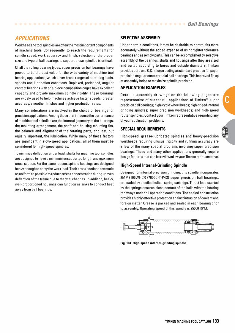
Ball Bearings
C
TIMKEN MACHINE TOOL CATALOG 133
APPLICATIONSWorkhead and tool spindles are often the most important components of machine tools. Consequently, to reach the requirements for spindle speed, work accuracy and finish, selection of the proper size and type of ball bearings to support these spindles is critical.
Of all the rolling bearing types, super precision ball bearings have proved to be the best value for the wide variety of machine tool bearing applications, which cover broad ranges of operating loads, speeds and lubrication conditions. Duplexed, preloaded, angular contact bearings with one-piece composition cages have excellent capacity and provide maximum spindle rigidity. These bearings are widely used to help machines achieve faster speeds, greater accuracy, smoother finishes and higher production rates.
Many considerations are involved in the choice of bearings for precision applications. Among those that influence the performance of machine tool spindles are the internal geometry of the bearings, the mounting arrangement, the shaft and housing mounting fits, the balance and alignment of the rotating parts, and last, but equally important, the lubrication. While many of these factors are significant in slow-speed applications, all of them must be considered for high-speed spindles.
To minimize deflection under load, shafts for machine tool spindles are designed to have a minimum unsupported length and maximum cross section. For the same reason, spindle housings are designed heavy enough to carry the work load. Their cross sections are made as uniform as possible to reduce stress concentration during uneven deflection of the frame due to thermal changes. In addition, heavy, well-proportioned housings can function as sinks to conduct heat away from ball bearings.
Fig. 104. High-speed internal-grinding spindle.
SELECTIVE ASSEMBLY
Under certain conditions, it may be desirable to control fits more accurately without the added expense of using tighter tolerance bearings and assembly parts. This can be accomplished by selective assembly of the bearings, shafts and housings after they are sized and sorted according to bores and outside diameters. Timken provides bore and O.D. micron coding as standard practice for super precision angular contact radial ball bearings. This improved fit-up at assembly helps to maximize spindle precision.
APPLICATION EXAMPLES
Detailed assembly drawings on the following pages are representative of successful applications of Timken® super precision ball bearings; high-cycle wheel heads; high-speed internal grinding spindles; super precision workheads; and high-speed router spindles. Contact your Timken representative regarding any of your application problems.
SPECIAL REQUIREMENTS
High-speed, grease-lubricated spindles and heavy-precision workheads requiring unusual rigidity and running accuracy are a few of the many special problems involving super precision bearings. These and many other applications generally require design features that can be reviewed by your Timken representative.
High-Speed Internal-Grinding Spindle
Designed for internal precision grinding, this spindle incorporates 2MM9106WI-CR (7006C-T-P4S) super precision ball bearings, preloaded by a coiled helical spring cartridge. Thrust load exerted by the springs ensures close contact of the balls with the bearing raceways under all operating conditions. The sealed construction provides highly effective protection against intrusion of coolant and foreign matter. Grease is packed and sealed in each bearing prior to assembly. Operating speed of this spindle is 25000 RPM.
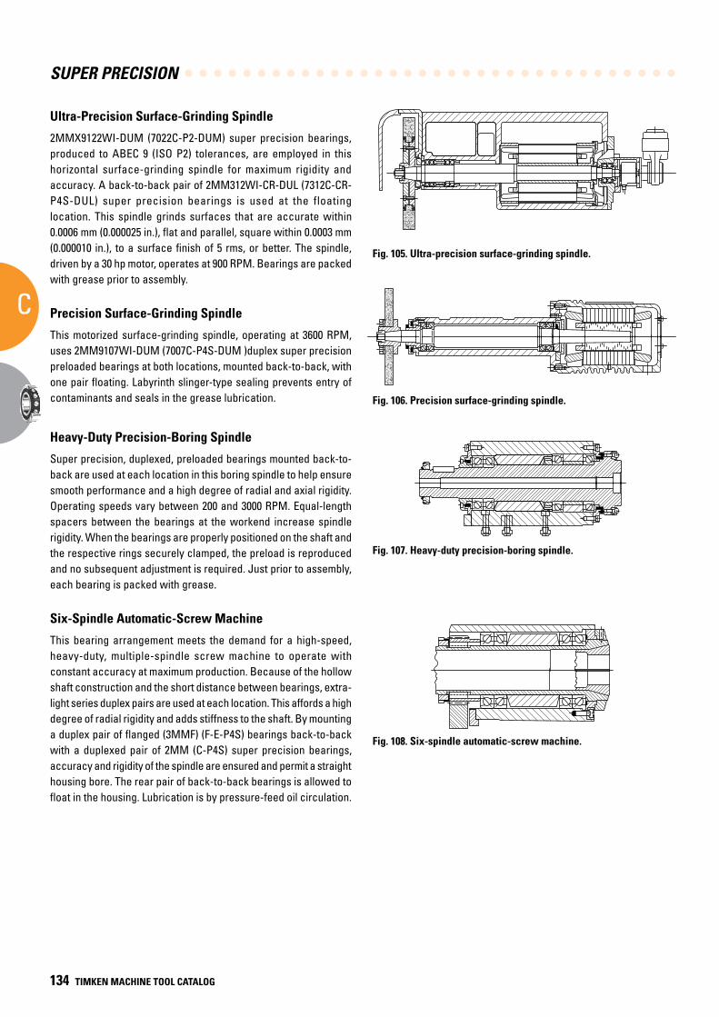
SUPER PRECISION
C
134 TIMKEN MACHINE TOOL CATALOG
Ultra-Precision Surface-Grinding Spindle
2MMX9122WI-DUM (7022C-P2-DUM) super precision bearings, produced to ABEC 9 (ISO P2) tolerances, are employed in this horizontal surface-grinding spindle for maximum rigidity and accuracy. A back-to-back pair of 2MM312WI-CR-DUL (7312C-CR-P4S-DUL) super precision bearings is used at the floating location. This spindle grinds surfaces that are accurate within 0.0006 mm (0.000025 in.), flat and parallel, square within 0.0003 mm (0.000010 in.), to a surface finish of 5 rms, or better. The spindle, driven by a 30 hp motor, operates at 900 RPM. Bearings are packed with grease prior to assembly.
Precision Surface-Grinding Spindle
This motorized surface-grinding spindle, operating at 3600 RPM, uses 2MM9107WI-DUM (7007C-P4S-DUM )duplex super precision preloaded bearings at both locations, mounted back-to-back, with one pair floating. Labyrinth slinger-type sealing prevents entry of contaminants and seals in the grease lubrication.
Heavy-Duty Precision-Boring Spindle
Super precision, duplexed, preloaded bearings mounted back-to-back are used at each location in this boring spindle to help ensure smooth performance and a high degree of radial and axial rigidity. Operating speeds vary between 200 and 3000 RPM. Equal-length spacers between the bearings at the workend increase spindle rigidity. When the bearings are properly positioned on the shaft and the respective rings securely clamped, the preload is reproduced and no subsequent adjustment is required. Just prior to assembly, each bearing is packed with grease.
Six-Spindle Automatic-Screw Machine
This bearing arrangement meets the demand for a high-speed, heavy-duty, multiple-spindle screw machine to operate with constant accuracy at maximum production. Because of the hollow shaft construction and the short distance between bearings, extra-light series duplex pairs are used at each location. This affords a high degree of radial rigidity and adds stiffness to the shaft. By mounting a duplex pair of flanged (3MMF) (F-E-P4S) bearings back-to-back with a duplexed pair of 2MM (C-P4S) super precision bearings, accuracy and rigidity of the spindle are ensured and permit a straight housing bore. The rear pair of back-to-back bearings is allowed to float in the housing. Lubrication is by pressure-feed oil circulation.
Fig. 105. Ultra-precision surface-grinding spindle.
Fig. 106. Precision surface-grinding spindle.
Fig. 107. Heavy-duty precision-boring spindle.
Fig. 108. Six-spindle automatic-screw machine.
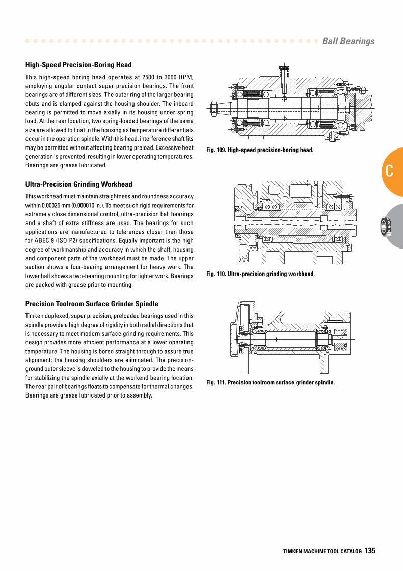
Ball Bearings
C
TIMKEN MACHINE TOOL CATALOG 135
High-Speed Precision-Boring Head
This high-speed boring head operates at 2500 to 3000 RPM, employing angular contact super precision bearings. The front bearings are of different sizes. The outer ring of the larger bearing abuts and is clamped against the housing shoulder. The inboard bearing is permitted to move axially in its housing under spring load. At the rear location, two spring-loaded bearings of the same size are allowed to float in the housing as temperature differentials occur in the operation spindle. With this head, interference shaft fits may be permitted without affecting bearing preload. Excessive heat generation is prevented, resulting in lower operating temperatures. Bearings are grease lubricated.
Ultra-Precision Grinding Workhead
This workhead must maintain straightness and roundness accuracy within 0.00025 mm (0.000010 in.). To meet such rigid requirements for extremely close dimensional control, ultra-precision ball bearings and a shaft of extra stiffness are used. The bearings for such applications are manufactured to tolerances closer than those for ABEC 9 (ISO P2) specifications. Equally important is the high degree of workmanship and accuracy in which the shaft, housing and component parts of the workhead must be made. The upper section shows a four-bearing arrangement for heavy work. The lower half shows a two-bearing mounting for lighter work. Bearings are packed with grease prior to mounting.
Precision Toolroom Surface Grinder Spindle
Timken duplexed, super precision, preloaded bearings used in this spindle provide a high degree of rigidity in both radial directions that is necessary to meet modern surface grinding requirements. This design provides more efficient performance at a lower operating temperature. The housing is bored straight through to assure true alignment; the housing shoulders are eliminated. The precision-ground outer sleeve is doweled to the housing to provide the means for stabilizing the spindle axially at the workend bearing location. The rear pair of bearings floats to compensate for thermal changes. Bearings are grease lubricated prior to assembly.
Fig. 109. High-speed precision-boring head.
Fig. 110. Ultra-precision grinding workhead.
Fig. 111. Precision toolroom surface grinder spindle.
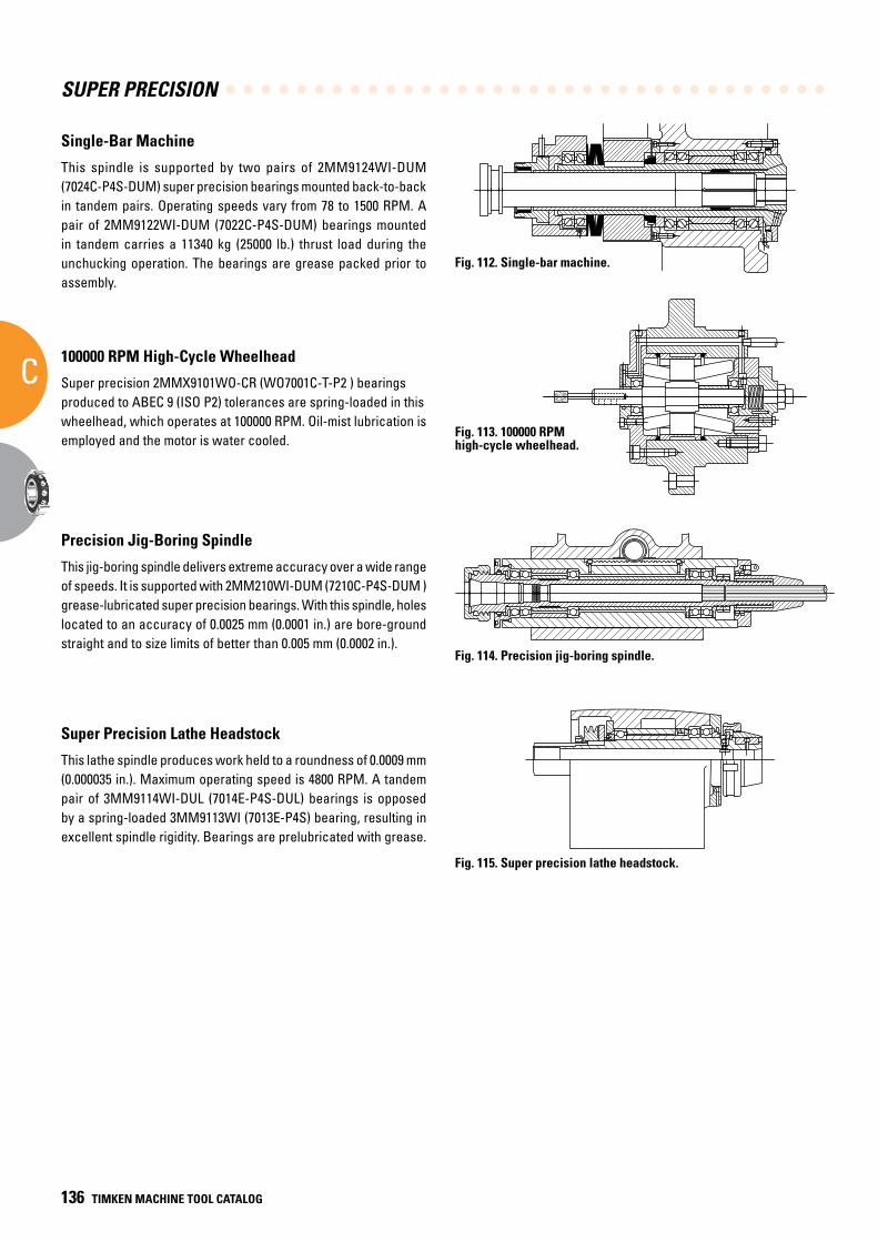
SUPER PRECISION
C
136 TIMKEN MACHINE TOOL CATALOG
Single-Bar Machine
This spindle is supported by two pairs of 2MM9124WI-DUM (7024C-P4S-DUM) super precision bearings mounted back-to-back in tandem pairs. Operating speeds vary from 78 to 1500 RPM. A pair of 2MM9122WI-DUM (7022C-P4S-DUM) bearings mounted in tandem carries a 11340 kg (25000 lb.) thrust load during the unchucking operation. The bearings are grease packed prior to assembly.
100000 RPM High-Cycle Wheelhead
Super precision 2MMX9101WO-CR (WO7001C-T-P2 ) bearings produced to ABEC 9 (ISO P2) tolerances are spring-loaded in this wheelhead, which operates at 100000 RPM. Oil-mist lubrication is employed and the motor is water cooled.
Precision Jig-Boring Spindle
This jig-boring spindle delivers extreme accuracy over a wide range of speeds. It is supported with 2MM210WI-DUM (7210C-P4S-DUM )grease-lubricated super precision bearings. With this spindle, holes located to an accuracy of 0.0025 mm (0.0001 in.) are bore-ground straight and to size limits of better than 0.005 mm (0.0002 in.).
Super Precision Lathe Headstock
This lathe spindle produces work held to a roundness of 0.0009 mm (0.000035 in.). Maximum operating speed is 4800 RPM. A tandem pair of 3MM9114WI-DUL (7014E-P4S-DUL) bearings is opposed by a spring-loaded 3MM9113WI (7013E-P4S) bearing, resulting in excellent spindle rigidity. Bearings are prelubricated with grease.
Fig. 112. Single-bar machine.
Fig. 113. 100000 RPM high-cycle wheelhead.
Fig. 114. Precision jig-boring spindle.
Fig. 115. Super precision lathe headstock.
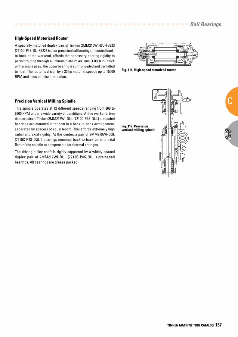
Ball Bearings
C
TIMKEN MACHINE TOOL CATALOG 137
High-Speed Motorized Router
A specially matched duplex pair of Timken 2MM210WI-DU-FS223 (7210C-P4S-DU-FS223 )super precision ball bearings, mounted back-to-back at the workend, affords the necessary bearing rigidity to permit routing through aluminum plate 25.400 mm (1.0000 in.) thick with a single pass. The upper bearing is spring-loaded and permitted to float. The router is driven by a 30 hp motor at speeds up to 15000 RPM and uses oil-mist lubrication.
Precision Vertical Milling Spindle
This spindle operates at 12 different speeds ranging from 260 to 6200 RPM under a wide variety of conditions. At the workend, two duplex pairs of Timken 2MM212WI-DUL (7212C-P4S-DUL) preloaded bearings are mounted in tandem in a back-to-back arrangement, separated by spacers of equal length. This affords extremely high radial and axial rigidity. At the center, a pair of 2MM210WI-DUL (7210C-P4S-DUL ) bearings mounted back-to-back permits axial float of the spindle to compensate for thermal changes.
The driving pulley shaft is rigidly supported by a widely spaced duplex pair of 2MM212WI-DUL (7212C-P4S-DUL ) preloaded bearings. All bearings are grease packed.
Fig. 116. High-speed motorized router.
Fig. 117. Precision vertical milling spindle.
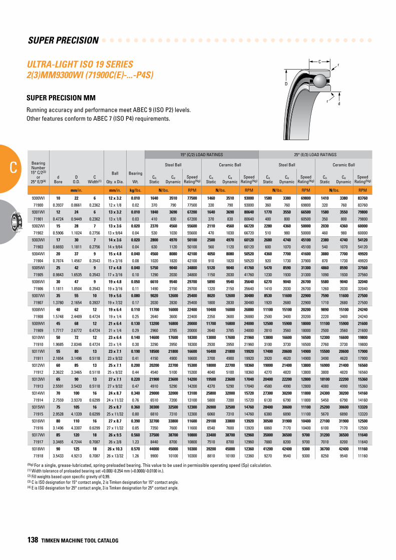
SUPER PRECISION
C
138 TIMKEN MACHINE TOOL CATALOG
C
D
r
dr
ULTRA-LIGHT ISO 19 SERIES 2(3)MM9300WI (71900C(E)-...-P4S)
SUPER PRECISION MM
Running accuracy and performance meet ABEC 9 (ISO P2) levels. Other features conform to ABEC 7 (ISO P4) requirements.
(Ng) For a single, grease-lubricated, spring-preloaded bearing. This value to be used in permissible operating speed (Sp) calculation.(1) Width tolerance of preloaded bearing set +0.000/-0.254 mm (+0.0000/-0.0100 in.).(2) Fill weights based upon specific gravity of 0,99.(3) C is ISO designation for 15° contact angle, 2 is Timken designation for 15° contact angle.(4) E is ISO designation for 25° contact angle, 3 is Timken designation for 25° contact angle.
BearingNumber15° C/2(3)
or25° E/3(4)
dBore
DO.D.
CWidth(1)
Ball Bearing
15° (C/2) LOAD RATINGS 25° (E/3) LOAD RATINGS
rRad.(2)
Suggested Shoulder Diameters Shaft Diameter Mounting Fits
FIXED FLOATING
Steel Ball Ceramic Ball Steel Ball Ceramic Ball Housing Bore (Stationary) Mounting Fits Housing Bore
(Stationary) Mounting Fits
CoStatic
CeDynamic
SpeedRating(Ng)
CoStatic
CeDynamic
SpeedRating(Ng)
CoStatic
CeDynamic
SpeedRating(Ng)
CoStatic
CeDynamic
SpeedRating(Ng)
Shaft Housing
Qty. x Dia. Wt. Max. Min. Max. Min. Max. Min. Loose Tight Max. Min. Tight Loose Max. Min. Loose Loose
mm/in. mm/in. kg/lbs. N/lbs. RPM N/lbs. RPM N/lbs. RPM N/lbs. RPM mm/in. mm/in. mm/in. mm/in. mm/in. mm/in. mm/in. mm/in. mm/in.
9300WI 10 22 6 12 x 3.2 0.010 1640 3510 77500 1460 3510 93000 1580 3380 69800 1410 3380 83760 0.3 13.2 13.0 19.6 19.3 10.000 9.995 0.005 0.004 22.005 22.000 0.000 0.010 22.010 22.005 0.015 0.005
71900 0.3937 0.8661 0.2362 12 x 1/8 0.02 370 790 77500 330 790 93000 360 760 69800 320 760 83760 0.012 0.52 0.51 0.77 0.76 0.39370 0.39350 0.00020 0.00015 0.86630 0.86610 0.00000 0.00040 0.86650 0.86630 0.00060 0.00020
9301WI 12 24 6 13 x 3.2 0.010 1840 3690 67200 1640 3690 80640 1770 3550 66500 1580 3550 79800 0.3 15.2 14.9 21.6 21.3 12.000 11.995 0.005 0.004 24.005 24.000 0.000 0.010 24.010 24.005 0.015 0.005
71901 0.4724 0.9449 0.2362 13 x 1/8 0.03 410 830 67200 370 830 80640 400 800 60500 350 800 79800 0.012 0.60 0.59 0.85 0.84 0.47240 0.47220 0.00020 0.00015 0.94510 0.94490 0.00000 0.00040 0.94530 0.94510 0.00060 0.00020
9302WI 15 28 7 13 x 3.6 0.020 2370 4560 55600 2110 4560 66720 2280 4360 50000 2030 4360 60000 0.3 18.3 18.1 25.5 25.2 15.000 14.995 0.005 0.004 28.005 28.000 0.000 0.010 28.010 28.005 0.015 0.005
71902 0.5906 1.1024 0.2756 13 x 9/64 0.04 530 1030 55600 470 1030 66720 510 980 50000 460 980 60000 0.012 0.72 0.71 1.00 0.99 0.59060 0.59040 0.00020 0.00015 1.02380 1.02360 0.00000 0.00040 1.02400 1.02380 0.00060 0.00020
9303WI 17 30 7 14 x 3.6 0.020 2800 4970 50100 2500 4970 60120 2680 4740 45100 2380 4740 54120 0.3 20.3 20.0 27.5 27.2 17.000 16.995 0.005 0.004 30.005 30.000 0.000 0.010 30.010 30.005 0.015 0.005
71903 0.6693 1.1811 0.2756 14 x 9/64 0.04 630 1120 50100 560 1120 60120 600 1070 45100 540 1070 54120 0.012 0.80 0.79 1.08 1.07 0.66930 0.66910 0.00020 0.00015 1.18130 1.18110 0.00000 0.00040 1.18150 1.18130 0.00060 0.00020
9304WI 20 37 9 15 x 4.8 0.040 4560 8080 42100 4050 8080 50520 4360 7700 41600 3880 7700 49920 0.3 24.1 23.9 33.7 33.4 20.000 19.995 0.005 0.005 37.006 37.000 0.000 0.012 37.010 37.005 0.016 0.005
71904 0.7874 1.4567 0.3543 15 x 3/16 0.08 1020 1820 42100 910 1820 50520 920 1730 37900 870 1730 49920 0.012 0.95 0.94 1.33 1.32 0.78740 0.78720 0.00020 0.00020 1.45700 1.45670 0.00000 0.00050 1.45710 1.45690 0.00070 0.00020
9305WI 25 42 9 17 x 4.8 0.040 5750 9040 34800 5120 9040 41760 5470 8590 31300 4860 8590 37560 0.3 29.1 28.9 38.7 38.4 25.000 24.995 0.005 0.005 42.006 42.000 0.000 0.012 42.010 42.005 0.016 0.005
71905 0.9843 1.6535 0.3543 17 x 3/16 0.10 1290 2030 34800 1150 2030 41760 1230 1930 31300 1090 1930 37560 0.012 1.15 1.14 1.52 1.51 0.98430 0.98410 0.00020 0.00020 1.65380 1.65350 0.00000 0.00050 1.65390 1.65370 0.00070 0.00020
9306WI 30 47 9 19 x 4.8 0.050 6610 9540 29700 5890 9540 35640 6270 9040 26700 5580 9040 32040 0.3 34.1 33.9 43.7 43.4 30.000 29.995 0.005 0.005 47.006 47.000 0.000 0.012 47.012 47.007 0.018 0.007
71906 1.1811 1.8504 0.3543 19 x 3/16 0.11 1490 2150 29700 1320 2150 35640 1410 2030 26700 1260 2030 32040 0.012 1.34 1.33 1.72 1.71 1.18110 1.18090 0.00020 0.00020 1.85070 1.85040 0.00000 0.00050 1.85090 1.85070 0.00080 0.00030
9307WI 35 55 10 19 x 5.6 0.080 9020 12600 25400 8020 12600 30480 8530 11600 22900 7590 11600 27500 0.6 40.0 39.5 51.1 50.6 35.000 34.995 0.005 0.006 55.008 55.000 0.000 0.015 55.012 55.007 0.019 0.007
71907 1.3780 2.1654 0.3937 19 x 7/32 0.17 2030 2830 25400 1800 2830 30480 1920 2680 22900 1710 2680 27500 0.024 1.57 1.55 2.01 1.99 1.37800 1.37780 0.00020 0.00025 2.16570 2.16540 0.00000 0.00060 2.16590 2.16570 0.00080 0.00030
9308WI 40 62 12 19 x 6.4 0.110 11700 16000 22400 10400 16000 26880 11100 15100 20200 9890 15100 24240 0.6 45.1 44.6 57.9 57.4 40.000 39.995 0.005 0.006 62.008 62.000 0.000 0.015 62.012 62.007 0.019 0.007
71908 1.5748 2.4409 0.4724 19 x 1/4 0.25 2640 3600 22400 2350 3600 26880 2500 3400 20200 2220 3400 24240 0.024 1.78 1.76 2.28 2.26 1.57480 1.57460 0.00020 0.00025 2.44120 2.44090 0.00000 0.00060 2.44140 2.44120 0.00080 0.00030
9309WI 45 68 12 21 x 6.4 0.130 13200 16800 20000 11700 16800 24000 12500 15900 18000 11100 15900 21600 0.6 50.7 50.1 63.4 62.9 45.000 44.995 0.005 0.006 68.008 68.000 0.000 0.015 68.012 68.007 0.019 0.007
71909 1.7717 2.6772 0.4724 21 x 1/4 0.29 2960 3785 20000 2640 3785 24000 2810 3560 18000 2500 3560 21600 0.024 1.99 1.97 2.50 2.48 1.77170 1.77150 0.00020 0.00025 2.67750 2.67720 0.00000 0.00060 2.67770 2.67750 0.00080 0.00030
9310WI 50 72 12 23 x 6.4 0.140 14600 17600 18300 13000 17600 21960 13800 16600 16500 12300 16600 19800 0.6 55.1 54.6 67.9 67.4 50.000 49.995 0.005 0.006 72.008 72.000 0.000 0.015 72.011 72.007 0.019 0.007
71910 1.9685 2.8346 0.4724 23 x 1/4 0.30 3290 3950 18300 2930 3950 21960 3100 3730 16500 2760 3730 19800 0.024 2.17 2.15 2.67 2.65 1.96850 1.96830 0.00020 0.00025 2.83490 2.83460 0.00000 0.00060 2.83510 2.83490 0.00080 0.00030
9311WI 55 80 13 23 x 7.1 0.190 18500 21800 16600 16400 21800 19920 17400 20600 14900 15500 20600 17900 1.0 60.9 60.4 75.2 74.7 55.000 54.995 0.005 0.007 80.008 80.000 0.000 0.015 80.012 80.008 0.020 0.008
71911 2.1654 3.1496 0.5118 23 x 9/32 0.41 4150 4900 16600 3700 4900 19920 3920 4620 14900 3490 4620 17900 0.039 2.40 2.38 2.96 2.94 2.16540 2.16520 0.00020 0.00030 3.14990 3.14960 0.00000 0.00060 3.15010 3.14990 0.00080 0.00030
9312WI 60 85 13 25 x 7.1 0.200 20200 22700 15300 18000 22700 18360 19000 21400 13800 16900 21400 16560 1.0 65.8 65.3 80.2 79.7 60.000 59.995 0.005 0.007 85.008 85.000 0.000 0.016 85.016 85.009 0.024 0.009
71912 2.3622 3.3465 0.5118 25 x 9/32 0.44 4540 5100 15300 4040 5100 18360 4270 4820 13800 3800 4820 16560 0.039 2.59 2.57 3.16 3.14 2.36220 2.36200 0.00020 0.00030 3.34680 3.34650 0.00000 0.00060 3.34710 3.34680 0.00090 0.00030
9313WI 65 90 13 27 x 7.1 0.220 21900 23600 14200 19500 23600 17040 20400 22200 12800 18100 22200 15360 1.0 70.8 70.3 85.2 84.7 65.000 64.995 0.005 0.007 90.008 90.000 0.000 0.016 90.015 90.007 0.023 0.007
71913 2.5591 3.5433 0.5118 27 x 9/32 0.47 4910 5290 14200 4370 5290 17040 4580 4990 12800 4080 4990 15360 0.039 2.79 2.77 3.35 3.33 2.55910 2.55890 0.00020 0.00030 3.54360 3.54330 0.00000 0.00060 3.54390 3.54360 0.00090 0.00030
9314WI 70 100 16 24 x 8.7 0.340 29000 32000 13100 25800 32000 15720 27300 30200 11800 24300 30200 14160 1.0 76.8 76.3 94.3 93.8 70.000 69.995 0.005 0.007 100.008 100.000 0.000 0.016 100.018 100.010 0.025 0.010
71914 2.7559 3.9370 0.6299 24 x 11/32 0.76 6510 7200 13100 5800 7200 15720 6130 6790 11800 5450 6790 14160 0.039 3.02 3.00 3.71 3.69 2.75590 2.75570 0.00020 0.00030 3.93730 3.93700 0.00000 0.00060 3.93770 3.93740 0.00100 0.00040
9315WI 75 105 16 25 x 8.7 0.360 30300 32500 12300 26900 32500 14760 28400 30600 11100 25200 30600 13320 1.0 81.9 81.1 99.4 98.6 75.005 74.995 0.005 0.012 105.008 105.000 0.000 0.016 105.019 105.011 0.026 0.011
71915 2.9528 4.1339 0.6299 25 x 11/32 0.80 6810 7310 12300 6060 7310 14760 6380 6890 11100 5670 6890 13320 0.039 3.22 3.19 3.91 3.88 2.95300 2.95260 0.00020 0.00050 4.13420 4.13390 0.00000 0.00060 4.13460 4.13430 0.00100 0.00040
9316WI 80 110 16 27 x 8.7 0.390 32700 33800 11600 29100 33800 13920 30500 31900 10400 27100 31900 12500 1.0 86.9 86.1 104.4 103.6 80.005 79.995 0.005 0.012 110.008 110.000 0.000 0.016 110.018 110.010 0.025 0.010
71916 3.1496 4.3307 0.6299 27 x 11/32 0.85 7350 7600 11600 6540 7600 13920 6860 7170 10400 6100 7170 12500 0.039 3.42 3.39 4.11 4.08 3.14980 3.14940 0.00020 0.00050 4.33100 4.33070 0.00000 0.00060 4.33140 4.33110 0.00100 0.00040
9317WI 85 120 18 26 x 9.5 0.560 37500 38700 10800 33400 38700 12960 35000 36500 9700 31200 36500 11640 1.0 93.6 92.8 112.7 111.9 85.005 84.995 0.005 0.012 120.008 120.000 0.000 0.016 120.018 120.010 0.025 0.010
71917 3.3465 4.7244 0.7087 26 x 3/8 1.23 8440 8700 10800 7510 8700 12960 7880 8200 9700 7010 8200 11640 0.039 3.69 3.66 4.44 4.41 3.34670 3.34630 0.00020 0.00050 4.72470 4.72440 0.00000 0.00060 4.72510 4.72480 0.00100 0.00040
9318WI 90 125 18 26 x 10.3 0.570 44000 45000 10300 39200 45000 12360 41200 42400 9300 36700 42400 11160 1.0 97.8 97.0 118.5 117.7 90.005 89.995 0.005 0.013 125.008 125.000 0.000 0.017 125.021 125.011 0.030 0.011
71918 3.5433 4.9213 0.7087 26 x 13/32 1.26 9900 10100 10300 8810 10100 12360 9270 9540 9300 8250 9540 11160 0.039 3.85 3.82 4.66 4.63 3.54350 3.54310 0.00020 0.00050 4.92160 4.92130 0.00000 0.00070 4.92210 4.92170 0.00120 0.00040
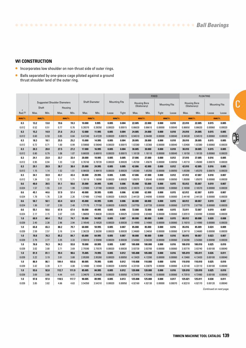
Ball Bearings
C
TIMKEN MACHINE TOOL CATALOG 139
WI CONSTRUCTION
• Incorporates low shoulder on non-thrust side of outer rings.
• Balls separated by one-piece cage piloted against a ground thrust shoulder land of the outer ring.
BearingNumber15° C/2(3)
or25° E/3(4)
dBore
DO.D.
CWidth(1)
Ball Bearing
15° (C/2) LOAD RATINGS 25° (E/3) LOAD RATINGS
rRad.(2)
Suggested Shoulder Diameters Shaft Diameter Mounting Fits
FIXED FLOATING
Steel Ball Ceramic Ball Steel Ball Ceramic Ball Housing Bore (Stationary) Mounting Fits Housing Bore
(Stationary) Mounting Fits
CoStatic
CeDynamic
SpeedRating(Ng)
CoStatic
CeDynamic
SpeedRating(Ng)
CoStatic
CeDynamic
SpeedRating(Ng)
CoStatic
CeDynamic
SpeedRating(Ng)
Shaft Housing
Qty. x Dia. Wt. Max. Min. Max. Min. Max. Min. Loose Tight Max. Min. Tight Loose Max. Min. Loose Loose
mm/in. mm/in. kg/lbs. N/lbs. RPM N/lbs. RPM N/lbs. RPM N/lbs. RPM mm/in. mm/in. mm/in. mm/in. mm/in. mm/in. mm/in. mm/in. mm/in.
9300WI 10 22 6 12 x 3.2 0.010 1640 3510 77500 1460 3510 93000 1580 3380 69800 1410 3380 83760 0.3 13.2 13.0 19.6 19.3 10.000 9.995 0.005 0.004 22.005 22.000 0.000 0.010 22.010 22.005 0.015 0.005
71900 0.3937 0.8661 0.2362 12 x 1/8 0.02 370 790 77500 330 790 93000 360 760 69800 320 760 83760 0.012 0.52 0.51 0.77 0.76 0.39370 0.39350 0.00020 0.00015 0.86630 0.86610 0.00000 0.00040 0.86650 0.86630 0.00060 0.00020
9301WI 12 24 6 13 x 3.2 0.010 1840 3690 67200 1640 3690 80640 1770 3550 66500 1580 3550 79800 0.3 15.2 14.9 21.6 21.3 12.000 11.995 0.005 0.004 24.005 24.000 0.000 0.010 24.010 24.005 0.015 0.005
71901 0.4724 0.9449 0.2362 13 x 1/8 0.03 410 830 67200 370 830 80640 400 800 60500 350 800 79800 0.012 0.60 0.59 0.85 0.84 0.47240 0.47220 0.00020 0.00015 0.94510 0.94490 0.00000 0.00040 0.94530 0.94510 0.00060 0.00020
9302WI 15 28 7 13 x 3.6 0.020 2370 4560 55600 2110 4560 66720 2280 4360 50000 2030 4360 60000 0.3 18.3 18.1 25.5 25.2 15.000 14.995 0.005 0.004 28.005 28.000 0.000 0.010 28.010 28.005 0.015 0.005
71902 0.5906 1.1024 0.2756 13 x 9/64 0.04 530 1030 55600 470 1030 66720 510 980 50000 460 980 60000 0.012 0.72 0.71 1.00 0.99 0.59060 0.59040 0.00020 0.00015 1.02380 1.02360 0.00000 0.00040 1.02400 1.02380 0.00060 0.00020
9303WI 17 30 7 14 x 3.6 0.020 2800 4970 50100 2500 4970 60120 2680 4740 45100 2380 4740 54120 0.3 20.3 20.0 27.5 27.2 17.000 16.995 0.005 0.004 30.005 30.000 0.000 0.010 30.010 30.005 0.015 0.005
71903 0.6693 1.1811 0.2756 14 x 9/64 0.04 630 1120 50100 560 1120 60120 600 1070 45100 540 1070 54120 0.012 0.80 0.79 1.08 1.07 0.66930 0.66910 0.00020 0.00015 1.18130 1.18110 0.00000 0.00040 1.18150 1.18130 0.00060 0.00020
9304WI 20 37 9 15 x 4.8 0.040 4560 8080 42100 4050 8080 50520 4360 7700 41600 3880 7700 49920 0.3 24.1 23.9 33.7 33.4 20.000 19.995 0.005 0.005 37.006 37.000 0.000 0.012 37.010 37.005 0.016 0.005
71904 0.7874 1.4567 0.3543 15 x 3/16 0.08 1020 1820 42100 910 1820 50520 920 1730 37900 870 1730 49920 0.012 0.95 0.94 1.33 1.32 0.78740 0.78720 0.00020 0.00020 1.45700 1.45670 0.00000 0.00050 1.45710 1.45690 0.00070 0.00020
9305WI 25 42 9 17 x 4.8 0.040 5750 9040 34800 5120 9040 41760 5470 8590 31300 4860 8590 37560 0.3 29.1 28.9 38.7 38.4 25.000 24.995 0.005 0.005 42.006 42.000 0.000 0.012 42.010 42.005 0.016 0.005
71905 0.9843 1.6535 0.3543 17 x 3/16 0.10 1290 2030 34800 1150 2030 41760 1230 1930 31300 1090 1930 37560 0.012 1.15 1.14 1.52 1.51 0.98430 0.98410 0.00020 0.00020 1.65380 1.65350 0.00000 0.00050 1.65390 1.65370 0.00070 0.00020
9306WI 30 47 9 19 x 4.8 0.050 6610 9540 29700 5890 9540 35640 6270 9040 26700 5580 9040 32040 0.3 34.1 33.9 43.7 43.4 30.000 29.995 0.005 0.005 47.006 47.000 0.000 0.012 47.012 47.007 0.018 0.007
71906 1.1811 1.8504 0.3543 19 x 3/16 0.11 1490 2150 29700 1320 2150 35640 1410 2030 26700 1260 2030 32040 0.012 1.34 1.33 1.72 1.71 1.18110 1.18090 0.00020 0.00020 1.85070 1.85040 0.00000 0.00050 1.85090 1.85070 0.00080 0.00030
9307WI 35 55 10 19 x 5.6 0.080 9020 12600 25400 8020 12600 30480 8530 11600 22900 7590 11600 27500 0.6 40.0 39.5 51.1 50.6 35.000 34.995 0.005 0.006 55.008 55.000 0.000 0.015 55.012 55.007 0.019 0.007
71907 1.3780 2.1654 0.3937 19 x 7/32 0.17 2030 2830 25400 1800 2830 30480 1920 2680 22900 1710 2680 27500 0.024 1.57 1.55 2.01 1.99 1.37800 1.37780 0.00020 0.00025 2.16570 2.16540 0.00000 0.00060 2.16590 2.16570 0.00080 0.00030
9308WI 40 62 12 19 x 6.4 0.110 11700 16000 22400 10400 16000 26880 11100 15100 20200 9890 15100 24240 0.6 45.1 44.6 57.9 57.4 40.000 39.995 0.005 0.006 62.008 62.000 0.000 0.015 62.012 62.007 0.019 0.007
71908 1.5748 2.4409 0.4724 19 x 1/4 0.25 2640 3600 22400 2350 3600 26880 2500 3400 20200 2220 3400 24240 0.024 1.78 1.76 2.28 2.26 1.57480 1.57460 0.00020 0.00025 2.44120 2.44090 0.00000 0.00060 2.44140 2.44120 0.00080 0.00030
9309WI 45 68 12 21 x 6.4 0.130 13200 16800 20000 11700 16800 24000 12500 15900 18000 11100 15900 21600 0.6 50.7 50.1 63.4 62.9 45.000 44.995 0.005 0.006 68.008 68.000 0.000 0.015 68.012 68.007 0.019 0.007
71909 1.7717 2.6772 0.4724 21 x 1/4 0.29 2960 3785 20000 2640 3785 24000 2810 3560 18000 2500 3560 21600 0.024 1.99 1.97 2.50 2.48 1.77170 1.77150 0.00020 0.00025 2.67750 2.67720 0.00000 0.00060 2.67770 2.67750 0.00080 0.00030
9310WI 50 72 12 23 x 6.4 0.140 14600 17600 18300 13000 17600 21960 13800 16600 16500 12300 16600 19800 0.6 55.1 54.6 67.9 67.4 50.000 49.995 0.005 0.006 72.008 72.000 0.000 0.015 72.011 72.007 0.019 0.007
71910 1.9685 2.8346 0.4724 23 x 1/4 0.30 3290 3950 18300 2930 3950 21960 3100 3730 16500 2760 3730 19800 0.024 2.17 2.15 2.67 2.65 1.96850 1.96830 0.00020 0.00025 2.83490 2.83460 0.00000 0.00060 2.83510 2.83490 0.00080 0.00030
9311WI 55 80 13 23 x 7.1 0.190 18500 21800 16600 16400 21800 19920 17400 20600 14900 15500 20600 17900 1.0 60.9 60.4 75.2 74.7 55.000 54.995 0.005 0.007 80.008 80.000 0.000 0.015 80.012 80.008 0.020 0.008
71911 2.1654 3.1496 0.5118 23 x 9/32 0.41 4150 4900 16600 3700 4900 19920 3920 4620 14900 3490 4620 17900 0.039 2.40 2.38 2.96 2.94 2.16540 2.16520 0.00020 0.00030 3.14990 3.14960 0.00000 0.00060 3.15010 3.14990 0.00080 0.00030
9312WI 60 85 13 25 x 7.1 0.200 20200 22700 15300 18000 22700 18360 19000 21400 13800 16900 21400 16560 1.0 65.8 65.3 80.2 79.7 60.000 59.995 0.005 0.007 85.008 85.000 0.000 0.016 85.016 85.009 0.024 0.009
71912 2.3622 3.3465 0.5118 25 x 9/32 0.44 4540 5100 15300 4040 5100 18360 4270 4820 13800 3800 4820 16560 0.039 2.59 2.57 3.16 3.14 2.36220 2.36200 0.00020 0.00030 3.34680 3.34650 0.00000 0.00060 3.34710 3.34680 0.00090 0.00030
9313WI 65 90 13 27 x 7.1 0.220 21900 23600 14200 19500 23600 17040 20400 22200 12800 18100 22200 15360 1.0 70.8 70.3 85.2 84.7 65.000 64.995 0.005 0.007 90.008 90.000 0.000 0.016 90.015 90.007 0.023 0.007
71913 2.5591 3.5433 0.5118 27 x 9/32 0.47 4910 5290 14200 4370 5290 17040 4580 4990 12800 4080 4990 15360 0.039 2.79 2.77 3.35 3.33 2.55910 2.55890 0.00020 0.00030 3.54360 3.54330 0.00000 0.00060 3.54390 3.54360 0.00090 0.00030
9314WI 70 100 16 24 x 8.7 0.340 29000 32000 13100 25800 32000 15720 27300 30200 11800 24300 30200 14160 1.0 76.8 76.3 94.3 93.8 70.000 69.995 0.005 0.007 100.008 100.000 0.000 0.016 100.018 100.010 0.025 0.010
71914 2.7559 3.9370 0.6299 24 x 11/32 0.76 6510 7200 13100 5800 7200 15720 6130 6790 11800 5450 6790 14160 0.039 3.02 3.00 3.71 3.69 2.75590 2.75570 0.00020 0.00030 3.93730 3.93700 0.00000 0.00060 3.93770 3.93740 0.00100 0.00040
9315WI 75 105 16 25 x 8.7 0.360 30300 32500 12300 26900 32500 14760 28400 30600 11100 25200 30600 13320 1.0 81.9 81.1 99.4 98.6 75.005 74.995 0.005 0.012 105.008 105.000 0.000 0.016 105.019 105.011 0.026 0.011
71915 2.9528 4.1339 0.6299 25 x 11/32 0.80 6810 7310 12300 6060 7310 14760 6380 6890 11100 5670 6890 13320 0.039 3.22 3.19 3.91 3.88 2.95300 2.95260 0.00020 0.00050 4.13420 4.13390 0.00000 0.00060 4.13460 4.13430 0.00100 0.00040
9316WI 80 110 16 27 x 8.7 0.390 32700 33800 11600 29100 33800 13920 30500 31900 10400 27100 31900 12500 1.0 86.9 86.1 104.4 103.6 80.005 79.995 0.005 0.012 110.008 110.000 0.000 0.016 110.018 110.010 0.025 0.010
71916 3.1496 4.3307 0.6299 27 x 11/32 0.85 7350 7600 11600 6540 7600 13920 6860 7170 10400 6100 7170 12500 0.039 3.42 3.39 4.11 4.08 3.14980 3.14940 0.00020 0.00050 4.33100 4.33070 0.00000 0.00060 4.33140 4.33110 0.00100 0.00040
9317WI 85 120 18 26 x 9.5 0.560 37500 38700 10800 33400 38700 12960 35000 36500 9700 31200 36500 11640 1.0 93.6 92.8 112.7 111.9 85.005 84.995 0.005 0.012 120.008 120.000 0.000 0.016 120.018 120.010 0.025 0.010
71917 3.3465 4.7244 0.7087 26 x 3/8 1.23 8440 8700 10800 7510 8700 12960 7880 8200 9700 7010 8200 11640 0.039 3.69 3.66 4.44 4.41 3.34670 3.34630 0.00020 0.00050 4.72470 4.72440 0.00000 0.00060 4.72510 4.72480 0.00100 0.00040
9318WI 90 125 18 26 x 10.3 0.570 44000 45000 10300 39200 45000 12360 41200 42400 9300 36700 42400 11160 1.0 97.8 97.0 118.5 117.7 90.005 89.995 0.005 0.013 125.008 125.000 0.000 0.017 125.021 125.011 0.030 0.011
71918 3.5433 4.9213 0.7087 26 x 13/32 1.26 9900 10100 10300 8810 10100 12360 9270 9540 9300 8250 9540 11160 0.039 3.85 3.82 4.66 4.63 3.54350 3.54310 0.00020 0.00050 4.92160 4.92130 0.00000 0.00070 4.92210 4.92170 0.00120 0.00040
Continued on next page.
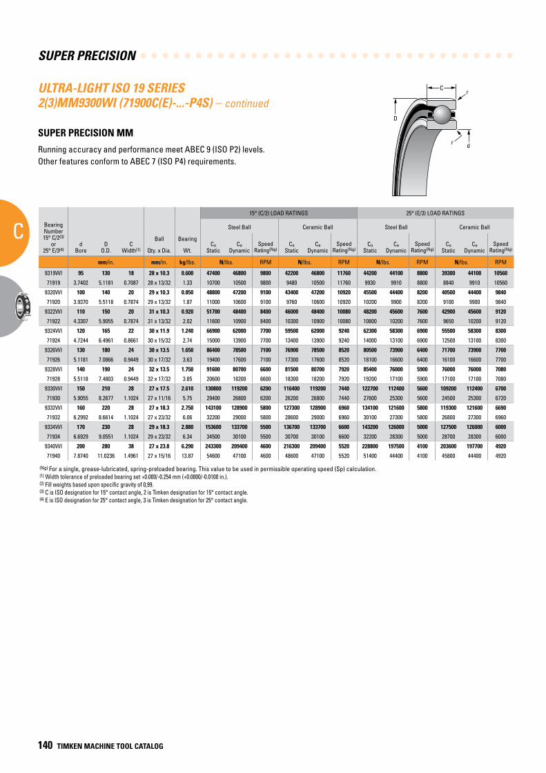
SUPER PRECISION
C
140 TIMKEN MACHINE TOOL CATALOG
C
D
r
dr
(Ng) For a single, grease-lubricated, spring-preloaded bearing. This value to be used in permissible operating speed (Sp) calculation.(1) Width tolerance of preloaded bearing set +0.000/-0.254 mm (+0.0000/-0.0100 in.).(2) Fill weights based upon specific gravity of 0,99.(3) C is ISO designation for 15° contact angle, 2 is Timken designation for 15° contact angle.(4) E is ISO designation for 25° contact angle, 3 is Timken designation for 25° contact angle.
ULTRA-LIGHT ISO 19 SERIES 2(3)MM9300WI (71900C(E)-...-P4S) – continued
SUPER PRECISION MM
Running accuracy and performance meet ABEC 9 (ISO P2) levels. Other features conform to ABEC 7 (ISO P4) requirements.
BearingNumber15° C/2(3)
or25° E/3(4)
dBore
DO.D.
CWidth(1)
Ball Bearing
15° (C/2) LOAD RATINGS 25° (E/3) LOAD RATINGS
rRad.(2)
Suggested Shoulder Diameters Shaft Diameter Mounting Fits
FIXED FLOATING
Steel Ball Ceramic Ball Steel Ball Ceramic Ball Housing Bore (Stationary) Mounting Fits Housing Bore
(Stationary) Mounting Fits
CoStatic
CeDynamic
SpeedRating(Ng)
CoStatic
CeDynamic
SpeedRating(Ng)
CoStatic
CeDynamic
SpeedRating(Ng)
CoStatic
CeDynamic
SpeedRating(Ng)
Shaft Housing
Qty. x Dia. Wt. Max. Min. Max. Min. Max. Min. Loose Tight Max. Min. Tight Loose Max. Min. Loose Loose
mm/in. mm/in. kg/lbs. N/lbs. RPM N/lbs. RPM N/lbs. RPM N/lbs. RPM mm/in. mm/in. mm/in. mm/in. mm/in. mm/in. mm/in. mm/in. mm/in.
9319WI 95 130 18 28 x 10.3 0.600 47400 46800 9800 42200 46800 11760 44200 44100 8800 39300 44100 10560 1.0 102.8 102.0 123.5 122.7 95.005 94.995 0.005 0.013 130.009 130.000 0.000 0.018 130.020 130.010 0.029 0.010
71919 3.7402 5.1181 0.7087 28 x 13/32 1.33 10700 10500 9800 9480 10500 11760 9930 9910 8800 8840 9910 10560 0.039 4.05 4.02 4.86 4.83 3.74040 3.74000 0.00020 0.00050 5.11850 5.11810 0.00000 0.00070 5.11890 5.11850 0.00110 0.00040
9320WI 100 140 20 29 x 10.3 0.850 48800 47200 9100 43400 47200 10920 45500 44400 8200 40500 44400 9840 1.0 110.3 109.5 131.0 130.2 100.005 99.995 0.005 0.013 140.009 140.000 0.000 0.018 140.020 140.010 0.029 0.010
71920 3.9370 5.5118 0.7874 29 x 13/32 1.87 11000 10600 9100 9760 10600 10920 10200 9900 8200 9100 9900 9840 0.039 4.34 4.31 5.16 5.13 3.93720 3.93680 0.00020 0.00050 5.51220 5.51180 0.00000 0.00070 5.51260 5.51220 0.00110 0.00040
9322WI 110 150 20 31 x 10.3 0.920 51700 48400 8400 46000 48400 10080 48200 45600 7600 42900 45600 9120 1.0 120.3 119.5 141.0 140.2 110.005 109.995 0.005 0.013 150.009 150.000 0.000 0.018 150.023 150.012 0.032 0.012
71922 4.3307 5.9055 0.7874 31 x 13/32 2.02 11600 10900 8400 10300 10900 10080 10800 10200 7600 9650 10200 9120 0.039 4.74 4.71 5.55 5.52 4.33090 4.33050 0.00020 0.00050 5.90590 5.90550 0.00000 0.00070 5.90640 5.90600 0.00120 0.00050
9324WI 120 165 22 30 x 11.9 1.240 66900 62000 7700 59500 62000 9240 62300 58300 6900 55500 58300 8300 1.0 131.2 130.4 155.0 154.3 120.005 119.995 0.005 0.013 165.010 165.000 0.000 0.020 165.022 165.012 0.032 0.012
71924 4.7244 6.4961 0.8661 30 x 15/32 2.74 15000 13900 7700 13400 13900 9240 14000 13100 6900 12500 13100 8300 0.039 5.16 5.13 6.10 6.07 4.72460 4.72420 0.00020 0.00050 6.49650 6.49610 0.00000 0.00080 6.49700 6.49660 0.00130 0.00050
9326WI 130 180 24 30 x 13.5 1.650 86400 78500 7100 76900 78500 8520 80500 73900 6400 71700 73900 7700 1.5 142.1 141.4 169.2 168.4 130.005 129.995 0.005 0.015 180.010 180.000 0.000 0.020 180.022 180.012 0.032 0.012
71926 5.1181 7.0866 0.9449 30 x 17/32 3.63 19400 17600 7100 17300 17600 8520 18100 16600 6400 16100 16600 7700 0.059 5.60 5.57 6.66 6.63 5.11830 5.11790 0.00020 0.00060 7.08700 7.08660 0.00000 0.00080 7.08750 7.08710 0.00130 0.00050
9328WI 140 190 24 32 x 13.5 1.750 91600 80700 6600 81500 80700 7920 85400 76000 5900 76000 76000 7080 1.5 152.1 151.4 179.2 178.4 140.005 139.995 0.005 0.015 190.010 190.000 0.000 0.021 190.022 190.012 0.033 0.012
71928 5.5118 7.4803 0.9449 32 x 17/32 3.85 20600 18200 6600 18300 18200 7920 19200 17100 5900 17100 17100 7080 0.059 5.99 5.96 7.05 7.02 5.51200 5.51160 0.00020 0.00060 7.48070 7.48030 0.00000 0.00080 7.48120 7.48080 0.00140 0.00050
9330WI 150 210 28 27 x 17.5 2.610 130800 119200 6200 116400 119200 7440 122700 112400 5600 109200 112400 6700 2.0 163.1 162.4 198.2 197.4 150.005 149.995 0.005 0.015 210.011 210.000 0.000 0.022 210.025 210.015 0.036 0.015
71930 5.9055 8.2677 1.1024 27 x 11/16 5.75 29400 26800 6200 26200 26800 7440 27600 25300 5600 24500 25300 6720 0.079 6.42 6.39 7.80 7.77 5.90570 5.90530 0.00020 0.00060 8.26820 8.26770 0.00000 0.00090 8.26870 8.26830 0.00150 0.00060
9332WI 160 220 28 27 x 18.3 2.750 143100 128900 5800 127300 128900 6960 134100 121600 5800 119300 121600 6690 2.0 173.2 172.4 208.2 207.4 160.005 159.995 0.005 0.015 220.011 220.000 0.000 0.022 220.025 220.015 0.036 0.015
71932 6.2992 8.6614 1.1024 27 x 23/32 6.06 32200 29000 5800 28600 29000 6960 30100 27300 5800 26800 27300 6960 0.079 6.82 6.79 8.20 8.17 6.29940 6.29900 0.00020 0.00060 8.66190 8.66140 0.00000 0.00090 8.66240 8.66200 0.00150 0.00060
9334WI 170 230 28 29 x 18.3 2.880 153600 133700 5500 136700 133700 6600 143200 126000 5000 127500 126000 6000 2.0 185.4 184.7 216.1 215.4 170.005 169.995 0.005 0.015 230.011 230.000 0.000 0.022 230.025 230.015 0.036 0.015
71934 6.6929 9.0551 1.1024 29 x 23/32 6.34 34500 30100 5500 30700 30100 6600 32200 28300 5000 28700 28300 6000 0.079 7.30 7.27 8.51 8.48 6.69310 6.69270 0.00020 0.00060 9.05560 9.05510 0.00000 0.00090 9.05610 9.05570 0.00150 0.00060
9340WI 200 280 38 27 x 23.8 6.290 243300 209400 4600 216300 209400 5520 228800 197500 4100 203600 197700 4920 2.1 216.8 216.0 264.5 263.7 200.008 199.993 0.007 0.019 280.013 280.000 0.000 0.026 280.031 280.018 0.044 0.018
71940 7.8740 11.0236 1.4961 27 x 15/16 13.87 54600 47100 4600 48600 47100 5520 51400 44400 4100 45800 44400 4920 0.083 8.54 8.51 10.41 10.38 7.87430 7.87370 0.00030 0.00080 11.02410 11.02360 0.00000 0.00100 11.02490 11.02440 0.00180 0.00080
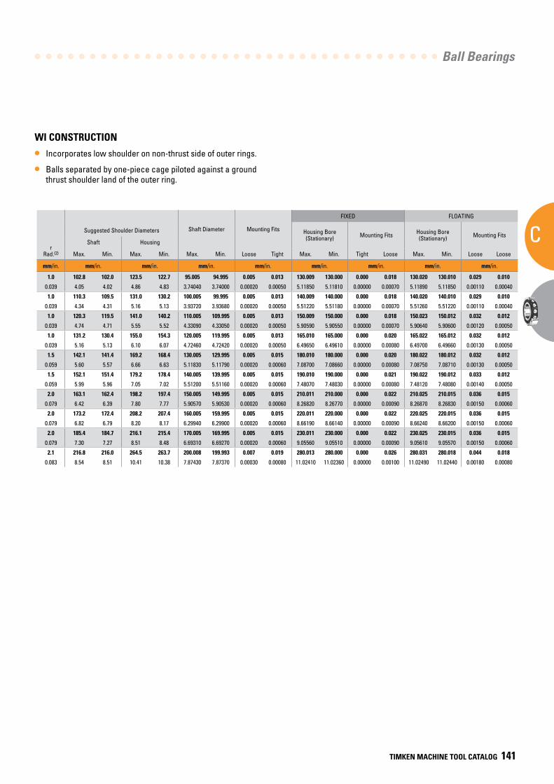
Ball Bearings
C
TIMKEN MACHINE TOOL CATALOG 141
WI CONSTRUCTION
• Incorporates low shoulder on non-thrust side of outer rings.
• Balls separated by one-piece cage piloted against a ground thrust shoulder land of the outer ring.
BearingNumber15° C/2(3)
or25° E/3(4)
dBore
DO.D.
CWidth(1)
Ball Bearing
15° (C/2) LOAD RATINGS 25° (E/3) LOAD RATINGS
rRad.(2)
Suggested Shoulder Diameters Shaft Diameter Mounting Fits
FIXED FLOATING
Steel Ball Ceramic Ball Steel Ball Ceramic Ball Housing Bore (Stationary) Mounting Fits Housing Bore
(Stationary) Mounting Fits
CoStatic
CeDynamic
SpeedRating(Ng)
CoStatic
CeDynamic
SpeedRating(Ng)
CoStatic
CeDynamic
SpeedRating(Ng)
CoStatic
CeDynamic
SpeedRating(Ng)
Shaft Housing
Qty. x Dia. Wt. Max. Min. Max. Min. Max. Min. Loose Tight Max. Min. Tight Loose Max. Min. Loose Loose
mm/in. mm/in. kg/lbs. N/lbs. RPM N/lbs. RPM N/lbs. RPM N/lbs. RPM mm/in. mm/in. mm/in. mm/in. mm/in. mm/in. mm/in. mm/in. mm/in.
9319WI 95 130 18 28 x 10.3 0.600 47400 46800 9800 42200 46800 11760 44200 44100 8800 39300 44100 10560 1.0 102.8 102.0 123.5 122.7 95.005 94.995 0.005 0.013 130.009 130.000 0.000 0.018 130.020 130.010 0.029 0.010
71919 3.7402 5.1181 0.7087 28 x 13/32 1.33 10700 10500 9800 9480 10500 11760 9930 9910 8800 8840 9910 10560 0.039 4.05 4.02 4.86 4.83 3.74040 3.74000 0.00020 0.00050 5.11850 5.11810 0.00000 0.00070 5.11890 5.11850 0.00110 0.00040
9320WI 100 140 20 29 x 10.3 0.850 48800 47200 9100 43400 47200 10920 45500 44400 8200 40500 44400 9840 1.0 110.3 109.5 131.0 130.2 100.005 99.995 0.005 0.013 140.009 140.000 0.000 0.018 140.020 140.010 0.029 0.010
71920 3.9370 5.5118 0.7874 29 x 13/32 1.87 11000 10600 9100 9760 10600 10920 10200 9900 8200 9100 9900 9840 0.039 4.34 4.31 5.16 5.13 3.93720 3.93680 0.00020 0.00050 5.51220 5.51180 0.00000 0.00070 5.51260 5.51220 0.00110 0.00040
9322WI 110 150 20 31 x 10.3 0.920 51700 48400 8400 46000 48400 10080 48200 45600 7600 42900 45600 9120 1.0 120.3 119.5 141.0 140.2 110.005 109.995 0.005 0.013 150.009 150.000 0.000 0.018 150.023 150.012 0.032 0.012
71922 4.3307 5.9055 0.7874 31 x 13/32 2.02 11600 10900 8400 10300 10900 10080 10800 10200 7600 9650 10200 9120 0.039 4.74 4.71 5.55 5.52 4.33090 4.33050 0.00020 0.00050 5.90590 5.90550 0.00000 0.00070 5.90640 5.90600 0.00120 0.00050
9324WI 120 165 22 30 x 11.9 1.240 66900 62000 7700 59500 62000 9240 62300 58300 6900 55500 58300 8300 1.0 131.2 130.4 155.0 154.3 120.005 119.995 0.005 0.013 165.010 165.000 0.000 0.020 165.022 165.012 0.032 0.012
71924 4.7244 6.4961 0.8661 30 x 15/32 2.74 15000 13900 7700 13400 13900 9240 14000 13100 6900 12500 13100 8300 0.039 5.16 5.13 6.10 6.07 4.72460 4.72420 0.00020 0.00050 6.49650 6.49610 0.00000 0.00080 6.49700 6.49660 0.00130 0.00050
9326WI 130 180 24 30 x 13.5 1.650 86400 78500 7100 76900 78500 8520 80500 73900 6400 71700 73900 7700 1.5 142.1 141.4 169.2 168.4 130.005 129.995 0.005 0.015 180.010 180.000 0.000 0.020 180.022 180.012 0.032 0.012
71926 5.1181 7.0866 0.9449 30 x 17/32 3.63 19400 17600 7100 17300 17600 8520 18100 16600 6400 16100 16600 7700 0.059 5.60 5.57 6.66 6.63 5.11830 5.11790 0.00020 0.00060 7.08700 7.08660 0.00000 0.00080 7.08750 7.08710 0.00130 0.00050
9328WI 140 190 24 32 x 13.5 1.750 91600 80700 6600 81500 80700 7920 85400 76000 5900 76000 76000 7080 1.5 152.1 151.4 179.2 178.4 140.005 139.995 0.005 0.015 190.010 190.000 0.000 0.021 190.022 190.012 0.033 0.012
71928 5.5118 7.4803 0.9449 32 x 17/32 3.85 20600 18200 6600 18300 18200 7920 19200 17100 5900 17100 17100 7080 0.059 5.99 5.96 7.05 7.02 5.51200 5.51160 0.00020 0.00060 7.48070 7.48030 0.00000 0.00080 7.48120 7.48080 0.00140 0.00050
9330WI 150 210 28 27 x 17.5 2.610 130800 119200 6200 116400 119200 7440 122700 112400 5600 109200 112400 6700 2.0 163.1 162.4 198.2 197.4 150.005 149.995 0.005 0.015 210.011 210.000 0.000 0.022 210.025 210.015 0.036 0.015
71930 5.9055 8.2677 1.1024 27 x 11/16 5.75 29400 26800 6200 26200 26800 7440 27600 25300 5600 24500 25300 6720 0.079 6.42 6.39 7.80 7.77 5.90570 5.90530 0.00020 0.00060 8.26820 8.26770 0.00000 0.00090 8.26870 8.26830 0.00150 0.00060
9332WI 160 220 28 27 x 18.3 2.750 143100 128900 5800 127300 128900 6960 134100 121600 5800 119300 121600 6690 2.0 173.2 172.4 208.2 207.4 160.005 159.995 0.005 0.015 220.011 220.000 0.000 0.022 220.025 220.015 0.036 0.015
71932 6.2992 8.6614 1.1024 27 x 23/32 6.06 32200 29000 5800 28600 29000 6960 30100 27300 5800 26800 27300 6960 0.079 6.82 6.79 8.20 8.17 6.29940 6.29900 0.00020 0.00060 8.66190 8.66140 0.00000 0.00090 8.66240 8.66200 0.00150 0.00060
9334WI 170 230 28 29 x 18.3 2.880 153600 133700 5500 136700 133700 6600 143200 126000 5000 127500 126000 6000 2.0 185.4 184.7 216.1 215.4 170.005 169.995 0.005 0.015 230.011 230.000 0.000 0.022 230.025 230.015 0.036 0.015
71934 6.6929 9.0551 1.1024 29 x 23/32 6.34 34500 30100 5500 30700 30100 6600 32200 28300 5000 28700 28300 6000 0.079 7.30 7.27 8.51 8.48 6.69310 6.69270 0.00020 0.00060 9.05560 9.05510 0.00000 0.00090 9.05610 9.05570 0.00150 0.00060
9340WI 200 280 38 27 x 23.8 6.290 243300 209400 4600 216300 209400 5520 228800 197500 4100 203600 197700 4920 2.1 216.8 216.0 264.5 263.7 200.008 199.993 0.007 0.019 280.013 280.000 0.000 0.026 280.031 280.018 0.044 0.018
71940 7.8740 11.0236 1.4961 27 x 15/16 13.87 54600 47100 4600 48600 47100 5520 51400 44400 4100 45800 44400 4920 0.083 8.54 8.51 10.41 10.38 7.87430 7.87370 0.00030 0.00080 11.02410 11.02360 0.00000 0.00100 11.02490 11.02440 0.00180 0.00080
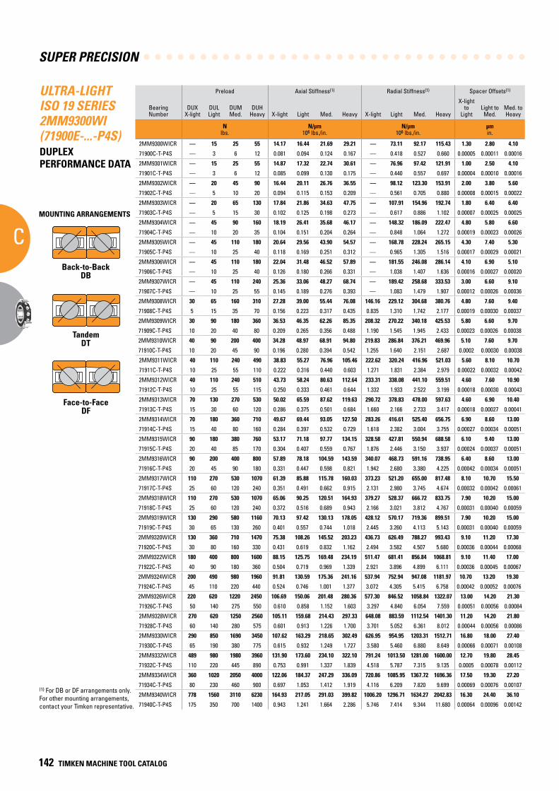
SUPER PRECISION
C
142 TIMKEN MACHINE TOOL CATALOG
ULTRA-LIGHT ISO 19 SERIES 2MM9300WI (71900E-...-P4S)DUPLEX PERFORMANCE DATA
Preload Axial Stiffness(1) Radial Stiffness(1) Spacer Offsets(1)
Bearing Number
DUXX-light
DULLight
DUMMed.
DUHHeavy X-light Light Med. Heavy X-light Light Med. Heavy
X-light to
LightLight toMed.
Med. toHeavy
N lbs.
N/µm 106 lbs./in.
N/µm 106 lbs./in.
µm in.
2MM9300WICR — 15 25 55 14.17 16.44 21.69 29.21 — 73.11 92.17 115.43 1.30 2.80 4.10
71900C-T-P4S — 3 6 12 0.081 0.094 0.124 0.167 — 0.418 0.527 0.660 0.00005 0.00011 0.00016
2MM9301WICR — 15 25 55 14.87 17.32 22.74 30.61 — 76.96 97.42 121.91 1.00 2.50 4.10
71901C-T-P4S — 3 6 12 0.085 0.099 0.130 0.175 — 0.440 0.557 0.697 0.00004 0.00010 0.00016
2MM9302WICR — 20 45 90 16.44 20.11 26.76 36.55 — 98.12 123.30 153.91 2.00 3.80 5.60
71902C-T-P4S — 5 10 20 0.094 0.115 0.153 0.209 — 0.561 0.705 0.880 0.00008 0.00015 0.00022
2MM9303WICR — 20 65 130 17.84 21.86 34.63 47.75 — 107.91 154.96 192.74 1.80 6.40 6.40
71903C-T-P4S — 5 15 30 0.102 0.125 0.198 0.273 — 0.617 0.886 1.102 0.00007 0.00025 0.00025
2MM9304WICR — 45 90 160 18.19 26.41 35.68 46.17 — 148.32 186.09 222.47 4.80 5.80 6.60
71904C-T-P4S — 10 20 35 0.104 0.151 0.204 0.264 — 0.848 1.064 1.272 0.00019 0.00023 0.00026
2MM9305WICR — 45 110 180 20.64 29.56 43.90 54.57 — 168.78 228.24 265.15 4.30 7.40 5.30
71905C-T-P4S — 10 25 40 0.118 0.169 0.251 0.312 — 0.965 1.305 1.516 0.00017 0.00029 0.00021
2MM9306WICR — 45 110 180 22.04 31.48 46.52 57.89 — 181.55 246.08 286.14 4.10 6.90 5.10
71906C-T-P4S — 10 25 40 0.126 0.180 0.266 0.331 — 1.038 1.407 1.636 0.00016 0.00027 0.00020
2MM9307WICR — 45 110 240 25.36 33.06 48.27 68.74 — 189.42 258.68 333.53 3.00 6.60 9.10
71907C-T-P4S — 10 25 55 0.145 0.189 0.276 0.393 — 1.083 1.479 1.907 0.00012 0.00026 0.00036
2MM9308WICR 30 65 160 310 27.28 39.00 55.44 76.08 146.16 229.12 304.68 380.76 4.80 7.60 9.40
71908C-T-P4S 5 15 35 70 0.156 0.223 0.317 0.435 0.835 1.310 1.742 2.177 0.00019 0.00030 0.00037
2MM9309WICR 30 90 180 360 36.53 46.35 62.26 85.35 208.32 270.22 340.18 425.53 5.80 6.60 9.70
71909C-T-P4S 10 20 40 80 0.209 0.265 0.356 0.488 1.190 1.545 1.945 2.433 0.00023 0.00026 0.00038
2MM9310WICR 40 90 200 400 34.28 48.97 68.91 94.80 219.83 286.84 376.21 469.96 5.10 7.60 9.70
71910C-T-P4S 10 20 45 90 0.196 0.280 0.394 0.542 1.255 1.640 2.151 2.687 0.0002 0.00030 0.00038
2MM9311WICR 40 110 240 490 38.83 55.27 76.96 105.46 222.62 320.24 416.96 521.03 5.60 8.10 10.70
71911C-T-P4S 10 25 55 110 0.222 0.316 0.440 0.603 1.271 1.831 2.384 2.979 0.00022 0.00032 0.00042
2MM9312WICR 40 110 240 510 43.73 58.24 80.63 112.64 233.31 338.08 441.10 559.51 4.60 7.60 10.90
71912C-T-P4S 10 25 55 115 0.250 0.333 0.461 0.644 1.332 1.933 2.522 3.199 0.00018 0.00030 0.00043
2MM9313WICR 70 130 270 530 50.02 65.59 87.62 119.63 290.72 378.83 478.00 597.63 4.60 6.90 10.40
71913C-T-P4S 15 30 60 120 0.286 0.375 0.501 0.684 1.660 2.166 2.733 3.417 0.00018 0.00027 0.00041
2MM9314WICR 70 180 360 710 49.67 69.44 93.05 127.50 283.26 416.61 525.40 656.75 6.90 8.60 13.00
71914C-T-P4S 15 40 80 160 0.284 0.397 0.532 0.729 1.618 2.382 3.004 3.755 0.00027 0.00034 0.00051
2MM9315WICR 90 180 380 760 53.17 71.18 97.77 134.15 328.58 427.81 550.94 688.58 6.10 9.40 13.00
71915C-T-P4S 20 40 85 170 0.304 0.407 0.559 0.767 1.876 2.446 3.150 3.937 0.00024 0.00037 0.00051
2MM9316WICR 90 200 400 800 57.89 78.18 104.59 143.59 340.07 468.73 591.16 738.95 6.40 8.60 13.00
71916C-T-P4S 20 45 90 180 0.331 0.447 0.598 0.821 1.942 2.680 3.380 4.225 0.00042 0.00034 0.00051
2MM9317WICR 110 270 530 1070 61.39 85.88 115.78 160.03 373.23 521.20 655.00 817.48 8.10 10.70 15.50
71917C-T-P4S 25 60 120 240 0.351 0.491 0.662 0.915 2.131 2.980 3.745 4.674 0.00032 0.00042 0.00061
2MM9318WICR 110 270 530 1070 65.06 90.25 120.51 164.93 379.27 528.37 666.72 833.75 7.90 10.20 15.00
71918C-T-P4S 25 60 120 240 0.372 0.516 0.689 0.943 2.166 3.021 3.812 4.767 0.00031 0.00040 0.00059
2MM9319WICR 130 290 580 1160 70.13 97.42 130.13 178.05 428.12 570.17 719.36 899.51 7.90 10.20 15.00
71919C-T-P4S 30 65 130 260 0.401 0.557 0.744 1.018 2.445 3.260 4.113 5.143 0.00031 0.00040 0.00059
2MM9320WICR 130 360 710 1470 75.38 108.26 145.52 203.23 436.73 626.49 788.27 993.43 9.10 11.20 17.30
71920C-T-P4S 30 80 160 330 0.431 0.619 0.832 1.162 2.494 3.582 4.507 5.680 0.00036 0.00044 0.00068
2MM9322WICR 180 400 800 1600 88.15 125.75 169.48 234.19 511.47 681.41 856.84 1068.81 9.10 11.40 17.00
71922C-T-P4S 40 90 180 360 0.504 0.719 0.969 1.339 2.921 3.896 4.899 6.111 0.00036 0.00045 0.00067
2MM9324WICR 200 490 980 1960 91.81 130.59 175.36 241.16 537.94 752.94 947.08 1181.97 10.70 13.20 19.30
71924C-T-P4S 45 110 220 440 0.524 0.746 1.001 1.377 3.072 4.305 5.415 6.758 0.00042 0.00052 0.00076
2MM9326WICR 220 620 1220 2450 106.69 150.06 201.48 280.36 577.30 846.52 1058.84 1322.07 13.00 14.20 21.30
71926C-T-P4S 50 140 275 550 0.610 0.858 1.152 1.603 3.297 4.840 6.054 7.559 0.00051 0.00056 0.00084
2MM9328WICR 270 620 1250 2560 105.11 159.68 214.43 297.33 648.08 883.59 1112.54 1401.30 11.20 14.20 21.80
71928C-T-P4S 60 140 280 575 0.601 0.913 1.226 1.700 3.701 5.052 6.361 8.012 0.00044 0.00056 0.00086
2MM9330WICR 290 850 1690 3450 107.62 163.29 218.65 302.49 626.95 954.95 1203.31 1512.71 16.80 18.00 27.40
71930C-T-P4S 65 190 380 775 0.615 0.932 1.249 1.727 3.580 5.460 6.880 8.649 0.00066 0.00071 0.00108
2MM9332WICR 489 980 1980 3960 131.90 173.60 234.10 322.10 791.24 1013.50 1281.00 1600.00 12.70 19.80 28.45
71932C-T-P4S 110 220 445 890 0.753 0.991 1.337 1.839 4.518 5.787 7.315 9.135 0.0005 0.00078 0.00112
2MM9334WICR 360 1020 2050 4000 122.06 184.37 247.29 336.09 720.86 1085.95 1367.72 1696.36 17.50 19.30 27.20
71934C-T-P4S 80 230 460 900 0.697 1.053 1.412 1.919 4.116 6.209 7.820 9.699 0.00069 0.00076 0.00107
2MM9340WICR 778 1560 3110 6230 164.93 217.05 291.03 399.82 1006.20 1296.71 1634.27 2042.83 16.30 24.40 36.10
71940C-T-P4S 175 350 700 1400 0.943 1.241 1.664 2.286 5.746 7.414 9.344 11.680 0.00064 0.00096 0.00142
(1) For DB or DF arrangements only. For other mounting arrangements, contact your Timken representative.
MOUNTING ARRANGEMENTS
Back-to-BackDB
TandemDT
Face-to-FaceDF
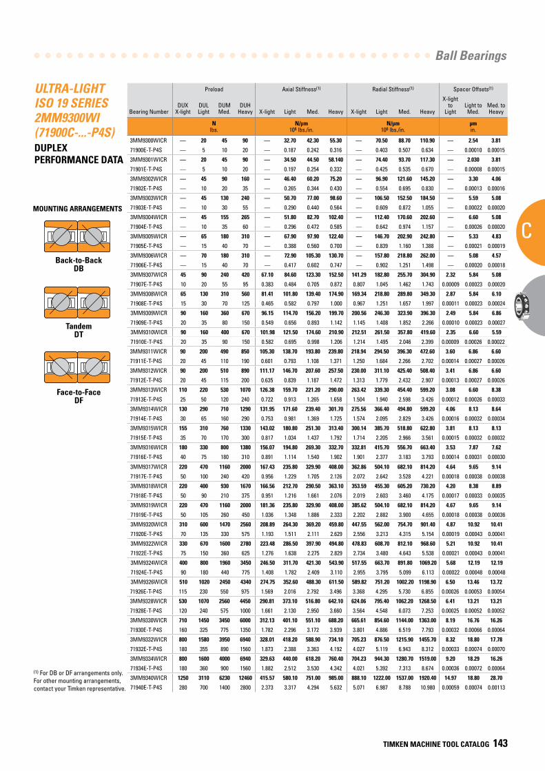
Ball Bearings
C
TIMKEN MACHINE TOOL CATALOG 143
ULTRA-LIGHT ISO 19 SERIES 2MM9300WI (71900C-...-P4S)DUPLEX PERFORMANCE DATA
Preload Axial Stiffness(1) Radial Stiffness(1) Spacer Offsets(1)
Bearing NumberDUX
X-lightDUL Light
DUM Med.
DUHHeavy X-light Light Med. Heavy X-light Light Med. Heavy
X-light to
LightLight to Med.
Med. to Heavy
N lbs.
N/µm 106 lbs./in.
N/µm 106 lbs./in.
µm in.
3MM9300WICR — 20 45 90 — 32.70 42.30 55.30 — 70.50 88.70 110.90 — 2.54 3.81
71900E-T-P4S — 5 10 20 — 0.187 0.242 0.316 — 0.403 0.507 0.634 — 0.00010 0.00015
3MM9301WICR — 20 45 90 — 34.50 44.50 58.140 — 74.40 93.70 117.30 — 2.030 3.81
71901E-T-P4S — 5 10 20 — 0.197 0.254 0.332 — 0.425 0.535 0.670 — 0.00008 0.00015
3MM9302WICR — 45 90 160 — 46.40 60.20 75.20 — 96.90 121.60 145.20 — 3.30 4.06
71902E-T-P4S — 10 20 35 — 0.265 0.344 0.430 — 0.554 0.695 0.830 — 0.00013 0.00016
3MM9303WICR — 45 130 240 — 50.70 77.00 98.60 — 106.50 152.50 184.50 — 5.59 5.08
71903E-T-P4S — 10 30 55 — 0.290 0.440 0.564 — 0.609 0.872 1.055 — 0.00022 0.00020
3MM9304WICR — 45 155 265 — 51.80 82.70 102.40 — 112.40 170.60 202.60 — 6.60 5.08
71904E-T-P4S — 10 35 60 — 0.296 0.472 0.585 — 0.642 0.974 1.157 — 0.00026 0.00020
3MM9305WICR — 65 180 310 — 67.90 97.90 122.40 — 146.70 202.90 242.80 — 5.33 4.83
71905E-T-P4S — 15 40 70 — 0.388 0.560 0.700 — 0.839 1.160 1.388 — 0.00021 0.00019
3MM9306WICR — 70 180 310 — 72.90 105.30 130.70 — 157.80 218.80 262.00 — 5.08 4.57
71906E-T-P4S — 15 40 70 — 0.417 0.602 0.747 — 0.902 1.251 1.498 — 0.00020 0.00018
3MM9307WICR 45 90 240 420 67.10 84.60 123.30 152.50 141.29 182.80 255.70 304.90 2.32 5.84 5.08
71907E-T-P4S 10 20 55 95 0.383 0.484 0.705 0.872 0.807 1.045 1.462 1.743 0.00009 0.00023 0.00020
3MM9308WICR 65 130 310 560 81.41 101.80 139.40 174.90 169.34 218.80 289.80 349.30 2.87 5.84 6.10
71908E-T-P4S 15 30 70 125 0.465 0.582 0.797 1.000 0.967 1.251 1.657 1.997 0.00011 0.00023 0.00024
3MM9309WICR 90 160 360 670 96.15 114.70 156.20 199.70 200.56 246.30 323.90 396.30 2.49 5.84 6.86
71909E-T-P4S 20 35 80 150 0.549 0.656 0.893 1.142 1.145 1.408 1.852 2.266 0.00010 0.00023 0.00027
3MM9310WICR 90 160 400 670 101.98 121.50 174.60 210.90 212.51 261.50 357.80 419.60 2.35 6.60 5.59
71910E-T-P4S 20 35 90 150 0.582 0.695 0.998 1.206 1.214 1.495 2.046 2.399 0.00009 0.00026 0.00022
3MM9311WICR 90 200 490 850 105.30 138.70 193.80 239.80 218.94 294.50 396.30 472.60 3.60 6.86 6.60
71911E-T-P4S 20 45 110 190 0.601 0.793 1.108 1.371 1.250 1.684 2.266 2.702 0.00014 0.00027 0.00026
3MM9312WICR 90 200 510 890 111.17 146.70 207.60 257.50 230.00 311.10 425.40 508.40 3.41 6.86 6.60
71912E-T-P4S 20 45 115 200 0.635 0.839 1.187 1.472 1.313 1.779 2.432 2.907 0.00013 0.00027 0.00026
3MM9313WICR 110 220 530 1070 126.38 159.70 221.20 290.00 263.42 339.30 454.40 599.20 3.08 6.60 8.38
71913E-T-P4S 25 50 120 240 0.722 0.913 1.265 1.658 1.504 1.940 2.598 3.426 0.00012 0.00026 0.00033
3MM9314WICR 130 290 710 1290 131.95 171.60 239.40 301.70 275.56 366.40 494.80 599.20 4.06 8.13 8.64
71914E-T-P4S 30 65 160 290 0.753 0.981 1.369 1.725 1.574 2.095 2.829 3.426 0.00016 0.00032 0.00034
3MM9315WICR 155 310 760 1330 143.02 180.80 251.30 313.40 300.14 385.70 518.80 622.80 3.81 8.13 8.13
71915E-T-P4S 35 70 170 300 0.817 1.034 1.437 1.792 1.714 2.205 2.966 3.561 0.00015 0.00032 0.00032
3MM9316WICR 180 330 800 1380 156.07 194.80 269.30 332.70 332.81 415.70 556.70 663.40 3.53 7.87 7.62
71916E-T-P4S 40 75 180 310 0.891 1.114 1.540 1.902 1.901 2.377 3.183 3.793 0.00014 0.00031 0.00030
3MM9317WICR 220 470 1160 2000 167.43 235.80 329.90 408.00 362.86 504.10 682.10 814.20 4.64 9.65 9.14
71917E-T-P4S 50 100 240 420 0.956 1.229 1.705 2.126 2.072 2.642 3.528 4.221 0.00018 0.00038 0.00038
3MM9318WICR 220 400 930 1670 166.56 212.70 290.50 363.10 353.59 455.30 605.20 730.20 4.20 8.38 8.89
71918E-T-P4S 50 90 210 375 0.951 1.216 1.661 2.076 2.019 2.603 3.460 4.175 0.00017 0.00033 0.00035
3MM9319WICR 220 470 1160 2000 181.36 235.80 329.90 408.00 385.62 504.10 682.10 814.20 4.67 9.65 9.14
71919E-T-P4S 50 105 260 450 1.036 1.348 1.886 2.333 2.202 2.882 3.900 4.655 0.00018 0.00038 0.00036
3MM9320WICR 310 600 1470 2560 208.89 264.30 369.20 459.80 447.55 562.00 754.70 901.40 4.87 10.92 10.41
71920E-T-P4S 70 135 330 575 1.193 1.511 2.111 2.629 2.556 3.213 4.315 5.154 0.00019 0.00043 0.00041
3MM9322WICR 330 670 1600 2780 223.48 286.50 397.90 494.80 478.83 608.70 812.10 968.60 5.21 10.92 10.41
71922E-T-P4S 75 150 360 625 1.276 1.638 2.275 2.829 2.734 3.480 4.643 5.538 0.00021 0.00043 0.00041
3MM9324WICR 400 800 1960 3450 246.50 311.70 421.30 543.90 517.55 663.70 891.80 1069.20 5.68 12.19 12.19
71924E-T-P4S 90 180 440 775 1.408 1.782 2.409 3.110 2.955 3.795 5.099 6.113 0.00022 0.00048 0.00048
3MM9326WICR 510 1020 2450 4340 274.75 352.60 488.30 611.50 589.82 751.20 1002.20 1198.90 6.50 13.46 13.72
71926E-T-P4S 115 230 550 975 1.569 2.016 2.792 3.496 3.368 4.295 5.730 6.855 0.00026 0.00053 0.00054
3MM9328WICR 530 1070 2560 4450 290.81 373.10 516.80 642.10 624.06 795.40 1062.20 1268.50 6.41 13.21 13.21
71928E-T-P4S 120 240 575 1000 1.661 2.130 2.950 3.660 3.564 4.548 6.073 7.253 0.00025 0.00052 0.00052
3MM9330WICR 710 1450 3450 6000 312.13 401.10 551.10 688.20 665.61 854.60 1144.00 1363.00 8.19 16.76 16.26
71930E-T-P4S 160 325 775 1350 1.782 2.296 3.172 3.939 3.801 4.886 6.519 7.793 0.00032 0.00066 0.00064
3MM9332WICR 800 1580 3950 6940 328.01 418.20 588.90 734.10 705.23 876.50 1215.90 1455.70 8.32 18.80 17.78
71932E-T-P4S 180 355 890 1560 1.873 2.388 3.363 4.192 4.027 5.119 6.943 8.312 0.00033 0.00074 0.00070
3MM9334WICR 800 1600 4000 6940 329.63 440.00 618.20 760.40 704.23 944.30 1280.70 1519.00 9.20 18.29 16.26
71934E-T-P4S 180 360 900 1560 1.882 2.512 3.530 4.342 4.021 5.392 7.313 8.674 0.00036 0.00072 0.00064
3MM9340WICR 1250 3110 6230 12460 415.57 580.10 751.00 985.00 888.10 1222.00 1537.00 1920.40 14.97 18.80 28.70
71940E-T-P4S 280 700 1400 2800 2.373 3.317 4.294 5.632 5.071 6.987 8.788 10.980 0.00059 0.00074 0.00113
(1) For DB or DF arrangements only. For other mounting arrangements, contact your Timken representative.
MOUNTING ARRANGEMENTS
Back-to-BackDB
TandemDT
Face-to-FaceDF
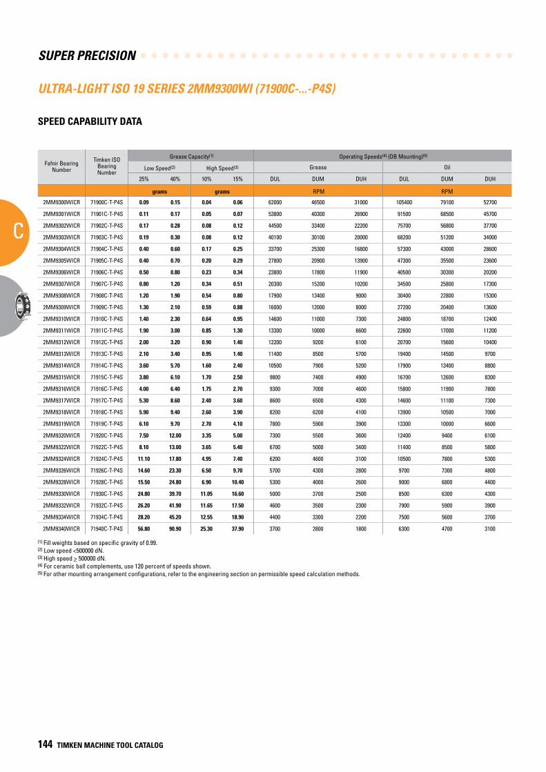
SUPER PRECISION
C
144 TIMKEN MACHINE TOOL CATALOG
ULTRA-LIGHT ISO 19 SERIES 2MM9300WI (71900C-...-P4S)
SPEED CAPABILITY DATA
Fafnir Bearing Number
Timken ISO Bearing Number
Grease Capacity(1) Operating Speeds(4) (DB Mounting)(5)
Low Speed(2) High Speed(3) Grease Oil
25% 40% 10% 15% DUL DUM DUH DUL DUM DUH
grams grams RPM RPM
2MM9300WICR 71900C-T-P4S 0.09 0.15 0.04 0.06 62000 46500 31000 105400 79100 52700
2MM9301WICR 71901C-T-P4S 0.11 0.17 0.05 0.07 53800 40300 26900 91500 68500 45700
2MM9302WICR 71902C-T-P4S 0.17 0.28 0.08 0.12 44500 33400 22200 75700 56800 37700
2MM9303WICR 71903C-T-P4S 0.19 0.30 0.08 0.12 40100 30100 20000 68200 51200 34000
2MM9304WICR 71904C-T-P4S 0.40 0.60 0.17 0.25 33700 25300 16800 57300 43000 28600
2MM9305WICR 71905C-T-P4S 0.40 0.70 0.20 0.29 27800 20900 13900 47300 35500 23600
2MM9306WICR 71906C-T-P4S 0.50 0.80 0.23 0.34 23800 17800 11900 40500 30300 20200
2MM9307WICR 71907C-T-P4S 0.80 1.20 0.34 0.51 20300 15200 10200 34500 25800 17300
2MM9308WICR 71908C-T-P4S 1.20 1.90 0.54 0.80 17900 13400 9000 30400 22800 15300
2MM9309WICR 71909C-T-P4S 1.30 2.10 0.59 0.88 16000 12000 8000 27200 20400 13600
2MM9310WICR 71910C-T-P4S 1.40 2.30 0.64 0.95 14600 11000 7300 24800 18700 12400
2MM9311WICR 71911C-T-P4S 1.90 3.00 0.85 1.30 13300 10000 6600 22600 17000 11200
2MM9312WICR 71912C-T-P4S 2.00 3.20 0.90 1.40 12200 9200 6100 20700 15600 10400
2MM9313WICR 71913C-T-P4S 2.10 3.40 0.95 1.40 11400 8500 5700 19400 14500 9700
2MM9314WICR 71914C-T-P4S 3.60 5.70 1.60 2.40 10500 7900 5200 17900 13400 8800
2MM9315WICR 71915C-T-P4S 3.80 6.10 1.70 2.50 9800 7400 4900 16700 12600 8300
2MM9316WICR 71916C-T-P4S 4.00 6.40 1.75 2.70 9300 7000 4600 15800 11900 7800
2MM9317WICR 71917C-T-P4S 5.30 8.60 2.40 3.60 8600 6500 4300 14600 11100 7300
2MM9318WICR 71918C-T-P4S 5.90 9.40 2.60 3.90 8200 6200 4100 13900 10500 7000
2MM9319WICR 71919C-T-P4S 6.10 9.70 2.70 4.10 7800 5900 3900 13300 10000 6600
2MM9320WICR 71920C-T-P4S 7.50 12.00 3.35 5.00 7300 5500 3600 12400 9400 6100
2MM9322WICR 71922C-T-P4S 8.10 13.00 3.65 5.40 6700 5000 3400 11400 8500 5800
2MM9324WICR 71924C-T-P4S 11.10 17.80 4.95 7.40 6200 4600 3100 10500 7800 5300
2MM9326WICR 71926C-T-P4S 14.60 23.30 6.50 9.70 5700 4300 2800 9700 7300 4800
2MM9328WICR 71928C-T-P4S 15.50 24.80 6.90 10.40 5300 4000 2600 9000 6800 4400
2MM9330WICR 71930C-T-P4S 24.80 39.70 11.05 16.60 5000 3700 2500 8500 6300 4300
2MM9332WICR 71932C-T-P4S 26.20 41.90 11.65 17.50 4600 3500 2300 7900 5900 3900
2MM9334WICR 71934C-T-P4S 28.20 45.20 12.55 18.90 4400 3300 2200 7500 5600 3700
2MM9340WICR 71940C-T-P4S 56.80 90.90 25.30 37.90 3700 2800 1800 6300 4700 3100
(1) Fill weights based on specific gravity of 0.99.(2) Low speed <500000 dN.(3) High speed > 500000 dN.(4) For ceramic ball complements, use 120 percent of speeds shown.(5) For other mounting arrangement configurations, refer to the engineering section on permissible speed calculation methods.
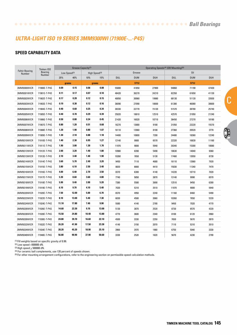
Ball Bearings
C
TIMKEN MACHINE TOOL CATALOG 145
ULTRA-LIGHT ISO 19 SERIES 3MM9300WI (71900E-...-P4S)
SPEED CAPABILITY DATA
Fafnir Bearing Number
Timken ISO Bearing Number
Grease Capacity(1) Operating Speeds(4) (DB Mounting)(5)
Low Speed(2) High Speed(3) Grease Oil
25% 40% 10% 15% DUL DUM DUH DUL DUM DUH
grams grams RPM RPM
3MM9300WICR 71900E-T-P4S 0.09 0.15 0.06 0.08 55800 41850 27900 94860 71190 47430
3MM9301WICR 71901E-T-P4S 0.11 0.17 0.07 0.10 48420 36270 24210 82350 61650 41130
3MM9302WICR 71902E-T-P4S 0.17 0.28 0.12 0.15 40050 30060 19980 68130 51120 33930
3MM9303WICR 71903E-T-P4S 0.19 0.30 0.12 0.16 36090 27090 18000 61380 46080 30600
3MM9304WICR 71904E-T-P4S 0.40 0.60 0.25 0.34 30330 22770 15120 51570 38700 25740
3MM9305WICR 71905E-T-P4S 0.40 0.70 0.29 0.39 25020 18810 12510 42570 31950 21240
3MM9306WICR 71906E-T-P4S 0.50 0.80 0.34 0.45 21420 16020 10710 36450 27270 18180
3MM9307WICR 71907E-T-P4S 0.80 1.20 0.51 0.68 18270 13680 9180 31050 23220 15570
3MM9308WICR 71908E-T-P4S 1.20 1.90 0.80 1.07 16110 12060 8100 27360 20520 3770
3MM9309WICR 71909E-T-P4S 1.30 2.10 0.88 1.18 14400 10800 7200 24480 18360 12240
3MM9310WICR 71910E-T-P4S 1.40 2.30 0.95 1.27 13140 9900 6570 22320 16830 11160
3MM9311WICR 71911E-T-P4S 1.90 3.00 1.30 1.70 11970 9000 5940 20340 15300 10080
3MM9312WICR 71912E-T-P4S 2.00 3.20 1.40 1.80 10980 8280 5490 18630 14040 9360
3MM9313WICR 71913E-T-P4S 2.10 3.40 1.40 1.90 10260 7650 5130 17460 13050 8730
3MM9314WICR 71914E-T-P4S 3.60 5.70 2.40 3.20 9450 7110 4680 16110 12060 7920
3MM9315WICR 71915E-T-P4S 3.80 6.10 2.50 3.40 8820 6660 4410 15030 11340 7470
3MM9316WICR 71916E-T-P4S 4.00 6.40 2.70 3.50 8370 6300 4140 14220 10710 7020
3MM9317WICR 71917E-T-P4S 5.30 8.60 3.60 4.80 7740 5850 3870 13140 9990 6570
3MM9318WICR 71918E-T-P4S 5.90 9.40 3.90 5.20 7380 5580 3690 12510 9450 6300
3MM9319WICR 71919E-T-P4S 6.10 9.70 4.10 5.40 7020 5310 3510 11970 9000 5940
3MM9320WICR 71920E-T-P4S 7.50 12.00 5.00 6.70 6570 4950 3240 11160 8460 5490
3MM9322WICR 71922E-T-P4S 8.10 13.00 5.40 7.30 6030 4500 3060 10260 7650 5220
3MM9324WICR 71924E-T-P4S 11.10 17.80 7.40 9.90 5580 4140 2790 9450 7020 4770
3MM9326WICR 71926E-T-P4S 14.60 23.30 9.70 13.00 5130 3870 2520 8730 6570 4320
3MM9328WICR 71928E-T-P4S 15.50 24.80 10.40 13.80 4770 3600 2340 8100 6120 3960
3MM9330WICR 71930E-T-P4S 24.80 39.70 16.60 22.10 4500 3330 2250 7650 5670 3870
3MM9332WICR 71932E-T-P4S 26.20 41.90 17.50 23.30 4140 3150 2070 7110 5310 3510
3MM9334WICR 71934E-T-P4S 28.20 45.20 18.90 25.10 3960 2970 1980 6750 5040 3330
3MM9340WICR 71940E-T-P4S 56.80 90.90 37.90 50.60 3330 2520 1620 5670 4230 2790
(1) Fill weights based on specific gravity of 0.99.(2) Low speed <500000 dN.(3) High speed > 500000 dN.(4) For ceramic ball complements, use 120 percent of speeds shown.(5) For other mounting arrangement configurations, refer to the engineering section on permissible speed calculation methods.
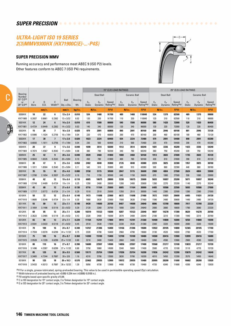
SUPER PRECISION
C
146 TIMKEN MACHINE TOOL CATALOG
C
D
r
dr
ULTRA-LIGHT ISO 19 SERIES 2(3)MMV9300HX (HX71900C(E)-...-P4S)
SUPER PRECISION MMV
Running accuracy and performance meet ABEC 9 (ISO P2) levels. Other features conform to ABEC 7 (ISO P4) requirements.
BearingNumber15° C/2(3)
or25° E/3(4)
dBore
DO.D.
CWidth(1)
Ball Bearing
15° (C/2) LOAD RATINGS 25° (E/3) LOAD RATINGS
rRad.(2)
Suggested Shoulder Diameters Shaft Diameter Mounting Fits
FIXED FLOATING
Steel Ball Ceramic Ball Steel Ball Ceramic Ball Housing Bore (Stationary) Mounting Fits Housing Bore
(Stationary) Mounting Fits
CoStatic
CeDynamic
SpeedRating(Ng)
CoStatic
CeDynamic
SpeedRating(Ng)
CoStatic
CeDynamic
SpeedRating(Ng)
CoStatic
CeDynamic
SpeedRating(Ng)
Shaft Housing
Qty. x Dia. Wt. Max. Min. Max. Min. Max. Min. Loose Tight Max. Min. Tight Loose Max. Min. Loose Loose
mm/in. mm/in. kg/lbs. N/lbs. RPM N/lbs. RPM N/lbs. RPM N/lbs. RPM mm/in. mm/in. mm/in. mm/in. mm/in. mm/in. mm/in. mm/in. mm/in.
9300HX 10 22 6 13 x 2.4 0.010 534 1468 91700 489 1468 110040 534 1379 82500 489 1379 99000 0.3 13.2 13.0 19.6 19.3 10.000 9.995 0.005 0.004 22.005 22.000 0.000 0.010 22.010 22.005 0.015 0.005
HX71900 0.3937 0.8661 0.2362 13 x 3/32 0.02 120 330 91700 110 330 110040 120 310 82500 110 310 99000 0.012 0.52 0.51 0.77 0.76 0.39370 0.39350 0.00020 0.00015 0.86630 0.86610 0.00000 0.00040 0.86650 0.86630 0.00060 0.00020
9301HX 12 24 6 14 x 2.4 0.010 610 1500 80000 540 1500 96000 580 1420 72000 520 1420 86400 0.3 15.2 14.9 21.6 21.3 12.000 11.995 0.005 0.004 24.005 24.000 0.000 0.010 24.010 24.005 0.015 0.005
HX71901 0.4724 0.9449 0.2362 14 x 3/32 0.03 140 340 80000 120 340 96000 130 320 72000 120 320 86400 0.012 0.60 0.59 0.85 0.84 0.47240 0.47220 0.00020 0.00015 0.94510 0.94490 0.00000 0.00040 0.94530 0.94510 0.00060 0.00020
9302HX 15 28 7 16 x 2.8 0.020 979 2091 66800 890 2091 80160 890 2046 60100 801 2046 72120 0.3 18.3 18.1 25.5 25.2 15.000 14.995 0.005 0.004 28.005 28.000 0.000 0.010 28.010 28.005 0.015 0.005
HX71902 0.5906 1.1024 0.2756 16 x 7/64 0.04 220 470 66800 200 470 80160 200 460 60100 180 460 72120 0.012 0.72 0.71 1.00 0.99 0.59060 0.59040 0.00020 0.00015 1.02380 1.02360 0.00000 0.00040 1.02400 1.02380 0.00060 0.00020
9303HX 17 30 7 17 x 2.8 0.020 1023 2224 60400 934 2224 72480 979 2091 54400 890 2091 65280 0.3 20.3 20.0 27.5 27.2 17.000 16.995 0.005 0.004 30.005 30.000 0.000 0.010 30.010 30.005 0.015 0.005
HX71903 0.6693 1.1811 0.2756 17 x 7/64 0.04 230 500 60400 210 500 72480 220 470 54400 200 470 65280 0.012 0.80 0.79 1.08 1.07 0.66930 0.66910 0.00020 0.00015 1.18130 1.18110 0.00000 0.00040 1.18150 1.18130 0.00060 0.00020
9304HX 20 37 9 17 x 3.6 0.040 1690 3514 50200 1512 3514 60240 1601 3336 45200 1423 3336 54240 0.3 24.1 23.9 33.7 33.4 20.000 19.995 0.005 0.005 37.006 37.000 0.000 0.012 37.010 37.005 0.016 0.005
HX71904 0.7874 1.4567 0.3543 17 x 9/64 0.08 380 790 50200 340 790 60240 360 750 45200 320 750 54240 0.012 0.95 0.94 1.33 1.32 0.78740 0.78720 0.00020 0.00020 1.45700 1.45670 0.00000 0.00050 1.45710 1.45690 0.00070 0.00020
9305HX 25 42 9 20 x 3.6 0.040 2020 3460 41800 1800 3460 50160 1913 3603 37600 1735 3603 45120 0.3 29.1 28.9 38.7 38.4 25.000 24.995 0.005 0.005 42.006 42.000 0.000 0.012 42.010 42.005 0.016 0.005
HX71905 0.9843 1.6535 0.3543 20 x 9/64 0.10 450 780 41800 400 780 50160 430 810 37600 390 810 45120 0.012 1.15 1.14 1.52 1.51 0.98430 0.98410 0.00020 0.00020 1.65380 1.65350 0.00000 0.00050 1.65390 1.65370 0.00070 0.00020
9306HX 30 47 9 23 x 3.6 0.050 2402 4048 35900 2135 4048 43080 2224 3825 32300 1957 3825 38760 0.3 34.1 33.9 43.7 43.4 30.000 29.995 0.005 0.005 47.006 47.000 0.000 0.012 47.012 47.007 0.018 0.007
HX71906 1.1811 1.8504 0.3543 23 x 9/64 0.11 540 910 35900 480 910 43080 500 860 32300 440 860 38760 0.012 1.34 1.33 1.72 1.71 1.18110 1.18090 0.00020 0.00020 1.85070 1.85040 0.00000 0.00050 1.85090 1.85070 0.00080 0.00030
9307HX 35 55 10 25 x 4.0 0.080 3158 5115 30500 2847 5115 36600 2980 4804 27500 2624 4804 33000 0.6 40.0 39.5 51.1 50.6 35.000 34.995 0.005 0.006 55.008 55.000 0.000 0.015 55.012 55.007 0.019 0.007
HX71907 1.3780 2.1654 0.3937 25 x 5/32 0.18 710 1150 30500 640 1150 36600 670 1080 27500 590 1080 33000 0.024 1.57 1.55 2.01 1.99 1.37800 1.37780 0.00020 0.00025 2.16570 2.16540 0.00000 0.00060 2.16590 2.16570 0.00080 0.00030
9308HX 40 62 12 19 x 6.4 0.110 6005 10675 28000 5338 10675 33600 5693 10097 25200 5071 10097 30240 0.6 45.1 44.6 57.9 57.4 40.000 39.995 0.005 0.006 62.008 62.000 0.000 0.015 62.012 62.007 0.019 0.007
HX71908 1.5748 2.4409 0.4724 19 x 1/4 0.25 1350 2400 28000 1200 2400 33600 1280 2270 25200 1140 2270 30240 0.024 1.78 1.76 2.28 2.26 1.57480 1.57460 0.00020 0.00025 2.44120 2.44090 0.00000 0.00060 2.44140 2.44120 0.00080 0.00030
9309HX 45 68 12 21 x 6.4 0.130 6716 11164 25000 6005 11164 30000 6405 10586 22500 5693 10586 27000 0.6 50.7 50.1 63.4 62.9 45.000 44.995 0.005 0.006 68.008 68.000 0.000 0.015 68.012 68.007 0.019 0.007
HX71909 1.7717 2.6772 0.4724 21 x 1/4 0.29 1510 2510 25000 1350 2510 30000 1440 2380 22500 1280 2380 27000 0.024 1.99 1.97 2.50 2.48 1.77170 1.77150 0.00020 0.00025 2.67750 2.67720 0.00000 0.00060 2.67770 2.67750 0.00080 0.00030
9310HX 50 72 12 23 x 6.4 0.140 7473 11698 22900 6672 11698 27480 7072 11031 20600 6405 11031 24720 0.6 55.1 54.6 67.9 67.4 50.000 49.995 0.005 0.006 72.008 72.000 0.000 0.015 72.011 72.007 0.019 0.007
HX71910 1.9685 2.8346 0.4724 23 x 1/4 0.30 1680 2630 22900 1500 2630 27480 1590 2480 20600 1440 2480 24720 0.024 2.17 2.15 2.67 2.65 1.96850 1.96830 0.00020 0.00025 2.83490 2.83460 0.00000 0.00060 2.83510 2.83490 0.00080 0.00030
9311HX 55 80 13 23 x 7.1 0.190 9430 14500 20700 8407 14500 24840 8896 13700 18600 7917 13700 22320 1.0 60.9 60.4 75.2 74.7 55.000 54.995 0.005 0.007 80.008 80.000 0.000 0.015 80.012 80.008 0.020 0.008
HX71911 2.1654 3.1496 0.5118 23 x 9/32 0.39 2120 3260 20700 1890 3260 24840 2000 3080 18600 1780 3080 22320 0.039 2.40 2.38 2.96 2.94 2.16540 2.16520 0.00020 0.00030 3.14990 3.14960 0.00000 0.00060 3.15010 3.14990 0.00080 0.00030
9312HX 60 85 13 25 x 7.1 0.200 10319 15123 19200 9207 15123 23040 9697 14278 17300 8629 14278 20760 1.0 65.8 65.3 80.2 79.7 60.000 59.995 0.005 0.007 85.008 85.000 0.000 0.016 85.016 85.009 0.024 0.009
HX71912 2.3622 3.3465 0.5118 25 x 9/32 0.43 2320 3400 19200 2070 3400 23040 2180 3210 17300 1940 3210 20760 0.039 2.59 2.57 3.16 3.14 2.36220 2.36200 0.00020 0.00030 3.34680 3.34650 0.00000 0.00060 3.34710 3.34680 0.00090 0.00030
9313HX 65 90 13 27 x 7.1 0.220 11164 15701 17800 9919 15701 21360 10400 14800 16000 9250 14800 19200 1.0 70.8 70.3 85.2 84.7 65.000 64.995 0.005 0.007 90.008 90.000 0.000 0.016 90.015 90.007 0.023 0.007
HX71913 2.5591 3.5433 0.5118 27 x 9/32 0.45 2510 3530 17800 2230 3530 21360 2340 3320 16000 2080 3320 19200 0.039 2.79 2.77 3.35 3.33 2.55910 2.55890 0.00020 0.00030 3.54360 3.54330 0.00000 0.00060 3.54390 3.54360 0.00090 0.00030
9314HX 70 100 16 24 x 8.7 0.340 14767 21306 16400 13166 21306 19680 13922 20105 14800 12365 20105 17760 1.0 76.8 76.3 94.3 93.8 70.000 69.995 0.005 0.007 100.008 100.000 0.000 0.016 100.018 100.010 0.025 0.010
HX71914 2.7559 3.9370 0.6299 24 x 11/32 0.75 3320 4790 16400 2960 4790 19680 3130 4520 14800 2780 4520 17760 0.039 3.02 3.00 3.71 3.69 2.75590 2.75570 0.00020 0.00030 3.93730 3.93700 0.00000 0.00060 3.93770 3.93740 0.00100 0.00040
9315HX 75 105 16 25 x 8.7 0.360 14300 15100 15400 12700 15100 18480 14500 20416 13900 12899 20416 16680 1.0 81.9 81.1 99.4 98.6 75.005 74.995 0.005 0.012 105.008 105.000 0.000 0.016 105.019 105.011 0.026 0.011
HX71915 2.9528 4.1339 0.6299 25 x 11/32 0.80 3210 3400 15400 2860 3400 18480 3260 4590 13900 2900 4590 16680 0.039 3.22 3.19 3.91 3.88 2.95300 2.95260 0.00020 0.00050 4.13420 4.13390 0.00000 0.00060 4.13460 4.13430 0.00100 0.00040
9316HX 80 110 16 27 x 8.7 0.390 16680 22507 14500 14856 22507 17400 15568 21217 13100 13833 21217 15720 1.0 86.9 86.1 104.4 103.6 80.005 79.995 0.005 0.012 110.008 110.000 0.000 0.016 110.018 110.010 0.025 0.010
HX71916 3.1496 4.3307 0.6299 27 x 11/32 0.80 3750 5060 14500 3340 5060 17400 3500 4770 13100 3110 4770 15720 0.039 3.42 3.39 4.11 4.08 3.14980 3.14940 0.00020 0.00050 4.33100 4.33070 0.00000 0.00060 4.33140 4.33110 0.00100 0.00040
9317HX 85 120 18 26 x 9.5 0.560 19171 25754 13500 17036 25754 16200 17836 24242 12200 15879 24242 14640 1.0 93.6 92.8 112.7 111.9 85.005 84.995 0.005 0.012 120.008 120.000 0.000 0.016 120.018 120.010 0.025 0.010
HX71917 3.3465 4.7244 0.7087 26 x 3/8 1.16 4310 5790 13500 3830 5790 16200 4010 5450 12200 3570 5450 14640 0.039 3.69 3.66 4.44 4.41 3.34670 3.34630 0.00020 0.00050 4.72470 4.72440 0.00000 0.00060 4.72510 4.72480 0.00100 0.00040
9318HX 90 125 18 26 x 10.3 0.570 22462 29935 12900 19972 29935 15480 20995 28200 11600 18682 28200 13920 1.0 97.8 97.0 118.5 117.7 90.005 89.995 0.005 0.013 125.008 125.000 0.000 0.017 125.021 125.011 0.030 0.011
HX71918 3.5433 4.9213 0.7087 26 x 13/32 1.20 5050 6730 12900 4490 6730 15480 4720 6340 11600 4200 6340 13920 0.039 3.85 3.82 4.66 4.63 3.54350 3.54310 0.00020 0.00050 4.92160 4.92130 0.00000 0.00070 4.92210 4.92170 0.00120 0.00040
(Ng) For a single, grease-lubricated, spring-preloaded bearing. This value to be used in permissible operating speed (Sp) calculation.(1) Width tolerance of preloaded bearing set +0.000/-0.254 mm (+0.0000/-0.0100 in.).(2) Fill weights based upon specific gravity of 0,99.(3) C is ISO designation for 15° contact angle, 2 is Timken designation for 15° contact angle.(4) E is ISO designation for 25° contact angle, 3 is Timken designation for 25° contact angle.

Ball Bearings
C
TIMKEN MACHINE TOOL CATALOG 147
WN CONSTRUCTION
• Incorporates low shoulder on non-thrust side of both inner and outer rings.
• Balls separated by one-piece cage piloted against a ground thrust shoulder land of the outer ring.
BearingNumber15° C/2(3)
or25° E/3(4)
dBore
DO.D.
CWidth(1)
Ball Bearing
15° (C/2) LOAD RATINGS 25° (E/3) LOAD RATINGS
rRad.(2)
Suggested Shoulder Diameters Shaft Diameter Mounting Fits
FIXED FLOATING
Steel Ball Ceramic Ball Steel Ball Ceramic Ball Housing Bore (Stationary) Mounting Fits Housing Bore
(Stationary) Mounting Fits
CoStatic
CeDynamic
SpeedRating(Ng)
CoStatic
CeDynamic
SpeedRating(Ng)
CoStatic
CeDynamic
SpeedRating(Ng)
CoStatic
CeDynamic
SpeedRating(Ng)
Shaft Housing
Qty. x Dia. Wt. Max. Min. Max. Min. Max. Min. Loose Tight Max. Min. Tight Loose Max. Min. Loose Loose
mm/in. mm/in. kg/lbs. N/lbs. RPM N/lbs. RPM N/lbs. RPM N/lbs. RPM mm/in. mm/in. mm/in. mm/in. mm/in. mm/in. mm/in. mm/in. mm/in.
9300HX 10 22 6 13 x 2.4 0.010 534 1468 91700 489 1468 110040 534 1379 82500 489 1379 99000 0.3 13.2 13.0 19.6 19.3 10.000 9.995 0.005 0.004 22.005 22.000 0.000 0.010 22.010 22.005 0.015 0.005
HX71900 0.3937 0.8661 0.2362 13 x 3/32 0.02 120 330 91700 110 330 110040 120 310 82500 110 310 99000 0.012 0.52 0.51 0.77 0.76 0.39370 0.39350 0.00020 0.00015 0.86630 0.86610 0.00000 0.00040 0.86650 0.86630 0.00060 0.00020
9301HX 12 24 6 14 x 2.4 0.010 610 1500 80000 540 1500 96000 580 1420 72000 520 1420 86400 0.3 15.2 14.9 21.6 21.3 12.000 11.995 0.005 0.004 24.005 24.000 0.000 0.010 24.010 24.005 0.015 0.005
HX71901 0.4724 0.9449 0.2362 14 x 3/32 0.03 140 340 80000 120 340 96000 130 320 72000 120 320 86400 0.012 0.60 0.59 0.85 0.84 0.47240 0.47220 0.00020 0.00015 0.94510 0.94490 0.00000 0.00040 0.94530 0.94510 0.00060 0.00020
9302HX 15 28 7 16 x 2.8 0.020 979 2091 66800 890 2091 80160 890 2046 60100 801 2046 72120 0.3 18.3 18.1 25.5 25.2 15.000 14.995 0.005 0.004 28.005 28.000 0.000 0.010 28.010 28.005 0.015 0.005
HX71902 0.5906 1.1024 0.2756 16 x 7/64 0.04 220 470 66800 200 470 80160 200 460 60100 180 460 72120 0.012 0.72 0.71 1.00 0.99 0.59060 0.59040 0.00020 0.00015 1.02380 1.02360 0.00000 0.00040 1.02400 1.02380 0.00060 0.00020
9303HX 17 30 7 17 x 2.8 0.020 1023 2224 60400 934 2224 72480 979 2091 54400 890 2091 65280 0.3 20.3 20.0 27.5 27.2 17.000 16.995 0.005 0.004 30.005 30.000 0.000 0.010 30.010 30.005 0.015 0.005
HX71903 0.6693 1.1811 0.2756 17 x 7/64 0.04 230 500 60400 210 500 72480 220 470 54400 200 470 65280 0.012 0.80 0.79 1.08 1.07 0.66930 0.66910 0.00020 0.00015 1.18130 1.18110 0.00000 0.00040 1.18150 1.18130 0.00060 0.00020
9304HX 20 37 9 17 x 3.6 0.040 1690 3514 50200 1512 3514 60240 1601 3336 45200 1423 3336 54240 0.3 24.1 23.9 33.7 33.4 20.000 19.995 0.005 0.005 37.006 37.000 0.000 0.012 37.010 37.005 0.016 0.005
HX71904 0.7874 1.4567 0.3543 17 x 9/64 0.08 380 790 50200 340 790 60240 360 750 45200 320 750 54240 0.012 0.95 0.94 1.33 1.32 0.78740 0.78720 0.00020 0.00020 1.45700 1.45670 0.00000 0.00050 1.45710 1.45690 0.00070 0.00020
9305HX 25 42 9 20 x 3.6 0.040 2020 3460 41800 1800 3460 50160 1913 3603 37600 1735 3603 45120 0.3 29.1 28.9 38.7 38.4 25.000 24.995 0.005 0.005 42.006 42.000 0.000 0.012 42.010 42.005 0.016 0.005
HX71905 0.9843 1.6535 0.3543 20 x 9/64 0.10 450 780 41800 400 780 50160 430 810 37600 390 810 45120 0.012 1.15 1.14 1.52 1.51 0.98430 0.98410 0.00020 0.00020 1.65380 1.65350 0.00000 0.00050 1.65390 1.65370 0.00070 0.00020
9306HX 30 47 9 23 x 3.6 0.050 2402 4048 35900 2135 4048 43080 2224 3825 32300 1957 3825 38760 0.3 34.1 33.9 43.7 43.4 30.000 29.995 0.005 0.005 47.006 47.000 0.000 0.012 47.012 47.007 0.018 0.007
HX71906 1.1811 1.8504 0.3543 23 x 9/64 0.11 540 910 35900 480 910 43080 500 860 32300 440 860 38760 0.012 1.34 1.33 1.72 1.71 1.18110 1.18090 0.00020 0.00020 1.85070 1.85040 0.00000 0.00050 1.85090 1.85070 0.00080 0.00030
9307HX 35 55 10 25 x 4.0 0.080 3158 5115 30500 2847 5115 36600 2980 4804 27500 2624 4804 33000 0.6 40.0 39.5 51.1 50.6 35.000 34.995 0.005 0.006 55.008 55.000 0.000 0.015 55.012 55.007 0.019 0.007
HX71907 1.3780 2.1654 0.3937 25 x 5/32 0.18 710 1150 30500 640 1150 36600 670 1080 27500 590 1080 33000 0.024 1.57 1.55 2.01 1.99 1.37800 1.37780 0.00020 0.00025 2.16570 2.16540 0.00000 0.00060 2.16590 2.16570 0.00080 0.00030
9308HX 40 62 12 19 x 6.4 0.110 6005 10675 28000 5338 10675 33600 5693 10097 25200 5071 10097 30240 0.6 45.1 44.6 57.9 57.4 40.000 39.995 0.005 0.006 62.008 62.000 0.000 0.015 62.012 62.007 0.019 0.007
HX71908 1.5748 2.4409 0.4724 19 x 1/4 0.25 1350 2400 28000 1200 2400 33600 1280 2270 25200 1140 2270 30240 0.024 1.78 1.76 2.28 2.26 1.57480 1.57460 0.00020 0.00025 2.44120 2.44090 0.00000 0.00060 2.44140 2.44120 0.00080 0.00030
9309HX 45 68 12 21 x 6.4 0.130 6716 11164 25000 6005 11164 30000 6405 10586 22500 5693 10586 27000 0.6 50.7 50.1 63.4 62.9 45.000 44.995 0.005 0.006 68.008 68.000 0.000 0.015 68.012 68.007 0.019 0.007
HX71909 1.7717 2.6772 0.4724 21 x 1/4 0.29 1510 2510 25000 1350 2510 30000 1440 2380 22500 1280 2380 27000 0.024 1.99 1.97 2.50 2.48 1.77170 1.77150 0.00020 0.00025 2.67750 2.67720 0.00000 0.00060 2.67770 2.67750 0.00080 0.00030
9310HX 50 72 12 23 x 6.4 0.140 7473 11698 22900 6672 11698 27480 7072 11031 20600 6405 11031 24720 0.6 55.1 54.6 67.9 67.4 50.000 49.995 0.005 0.006 72.008 72.000 0.000 0.015 72.011 72.007 0.019 0.007
HX71910 1.9685 2.8346 0.4724 23 x 1/4 0.30 1680 2630 22900 1500 2630 27480 1590 2480 20600 1440 2480 24720 0.024 2.17 2.15 2.67 2.65 1.96850 1.96830 0.00020 0.00025 2.83490 2.83460 0.00000 0.00060 2.83510 2.83490 0.00080 0.00030
9311HX 55 80 13 23 x 7.1 0.190 9430 14500 20700 8407 14500 24840 8896 13700 18600 7917 13700 22320 1.0 60.9 60.4 75.2 74.7 55.000 54.995 0.005 0.007 80.008 80.000 0.000 0.015 80.012 80.008 0.020 0.008
HX71911 2.1654 3.1496 0.5118 23 x 9/32 0.39 2120 3260 20700 1890 3260 24840 2000 3080 18600 1780 3080 22320 0.039 2.40 2.38 2.96 2.94 2.16540 2.16520 0.00020 0.00030 3.14990 3.14960 0.00000 0.00060 3.15010 3.14990 0.00080 0.00030
9312HX 60 85 13 25 x 7.1 0.200 10319 15123 19200 9207 15123 23040 9697 14278 17300 8629 14278 20760 1.0 65.8 65.3 80.2 79.7 60.000 59.995 0.005 0.007 85.008 85.000 0.000 0.016 85.016 85.009 0.024 0.009
HX71912 2.3622 3.3465 0.5118 25 x 9/32 0.43 2320 3400 19200 2070 3400 23040 2180 3210 17300 1940 3210 20760 0.039 2.59 2.57 3.16 3.14 2.36220 2.36200 0.00020 0.00030 3.34680 3.34650 0.00000 0.00060 3.34710 3.34680 0.00090 0.00030
9313HX 65 90 13 27 x 7.1 0.220 11164 15701 17800 9919 15701 21360 10400 14800 16000 9250 14800 19200 1.0 70.8 70.3 85.2 84.7 65.000 64.995 0.005 0.007 90.008 90.000 0.000 0.016 90.015 90.007 0.023 0.007
HX71913 2.5591 3.5433 0.5118 27 x 9/32 0.45 2510 3530 17800 2230 3530 21360 2340 3320 16000 2080 3320 19200 0.039 2.79 2.77 3.35 3.33 2.55910 2.55890 0.00020 0.00030 3.54360 3.54330 0.00000 0.00060 3.54390 3.54360 0.00090 0.00030
9314HX 70 100 16 24 x 8.7 0.340 14767 21306 16400 13166 21306 19680 13922 20105 14800 12365 20105 17760 1.0 76.8 76.3 94.3 93.8 70.000 69.995 0.005 0.007 100.008 100.000 0.000 0.016 100.018 100.010 0.025 0.010
HX71914 2.7559 3.9370 0.6299 24 x 11/32 0.75 3320 4790 16400 2960 4790 19680 3130 4520 14800 2780 4520 17760 0.039 3.02 3.00 3.71 3.69 2.75590 2.75570 0.00020 0.00030 3.93730 3.93700 0.00000 0.00060 3.93770 3.93740 0.00100 0.00040
9315HX 75 105 16 25 x 8.7 0.360 14300 15100 15400 12700 15100 18480 14500 20416 13900 12899 20416 16680 1.0 81.9 81.1 99.4 98.6 75.005 74.995 0.005 0.012 105.008 105.000 0.000 0.016 105.019 105.011 0.026 0.011
HX71915 2.9528 4.1339 0.6299 25 x 11/32 0.80 3210 3400 15400 2860 3400 18480 3260 4590 13900 2900 4590 16680 0.039 3.22 3.19 3.91 3.88 2.95300 2.95260 0.00020 0.00050 4.13420 4.13390 0.00000 0.00060 4.13460 4.13430 0.00100 0.00040
9316HX 80 110 16 27 x 8.7 0.390 16680 22507 14500 14856 22507 17400 15568 21217 13100 13833 21217 15720 1.0 86.9 86.1 104.4 103.6 80.005 79.995 0.005 0.012 110.008 110.000 0.000 0.016 110.018 110.010 0.025 0.010
HX71916 3.1496 4.3307 0.6299 27 x 11/32 0.80 3750 5060 14500 3340 5060 17400 3500 4770 13100 3110 4770 15720 0.039 3.42 3.39 4.11 4.08 3.14980 3.14940 0.00020 0.00050 4.33100 4.33070 0.00000 0.00060 4.33140 4.33110 0.00100 0.00040
9317HX 85 120 18 26 x 9.5 0.560 19171 25754 13500 17036 25754 16200 17836 24242 12200 15879 24242 14640 1.0 93.6 92.8 112.7 111.9 85.005 84.995 0.005 0.012 120.008 120.000 0.000 0.016 120.018 120.010 0.025 0.010
HX71917 3.3465 4.7244 0.7087 26 x 3/8 1.16 4310 5790 13500 3830 5790 16200 4010 5450 12200 3570 5450 14640 0.039 3.69 3.66 4.44 4.41 3.34670 3.34630 0.00020 0.00050 4.72470 4.72440 0.00000 0.00060 4.72510 4.72480 0.00100 0.00040
9318HX 90 125 18 26 x 10.3 0.570 22462 29935 12900 19972 29935 15480 20995 28200 11600 18682 28200 13920 1.0 97.8 97.0 118.5 117.7 90.005 89.995 0.005 0.013 125.008 125.000 0.000 0.017 125.021 125.011 0.030 0.011
HX71918 3.5433 4.9213 0.7087 26 x 13/32 1.20 5050 6730 12900 4490 6730 15480 4720 6340 11600 4200 6340 13920 0.039 3.85 3.82 4.66 4.63 3.54350 3.54310 0.00020 0.00050 4.92160 4.92130 0.00000 0.00070 4.92210 4.92170 0.00120 0.00040
HIGH-SPEED SEAL OPTION
Available with non-contact seals. Add VV suffix to part number (in place of CR cage designation). Ex: 2MMV9106HXVV SUL.
Continued on next page.
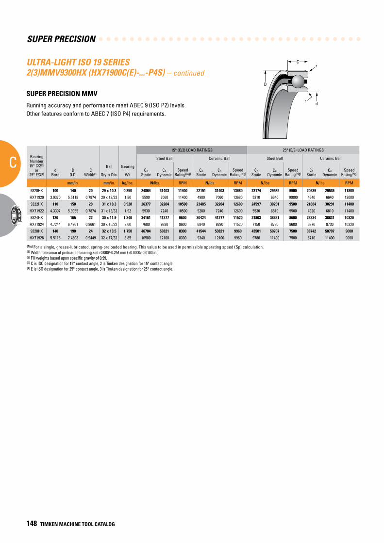
SUPER PRECISION
C
148 TIMKEN MACHINE TOOL CATALOG
C
D
r
dr
(Ng) For a single, grease-lubricated, spring-preloaded bearing. This value to be used in permissible operating speed (Sp) calculation.(1) Width tolerance of preloaded bearing set +0.000/-0.254 mm (+0.0000/-0.0100 in.).(2) Fill weights based upon specific gravity of 0,99.(3) C is ISO designation for 15° contact angle, 2 is Timken designation for 15° contact angle.(4) E is ISO designation for 25° contact angle, 3 is Timken designation for 25° contact angle.
BearingNumber15° C/2(3)
or25° E/3(4)
dBore
DO.D.
CWidth(1)
Ball Bearing
15° (C/2) LOAD RATINGS 25° (E/3) LOAD RATINGS
rRad.(2)
Suggested Shoulder Diameters Shaft Diameter Mounting Fits
FIXED FLOATING
Steel Ball Ceramic Ball Steel Ball Ceramic Ball Housing Bore (Stationary) Mounting Fits Housing Bore
(Stationary) Mounting Fits
CoStatic
CeDynamic
SpeedRating(Ng)
CoStatic
CeDynamic
SpeedRating(Ng)
CoStatic
CeDynamic
SpeedRating(Ng)
CoStatic
CeDynamic
SpeedRating(Ng)
Shaft Housing
Qty. x Dia. Wt. Max. Min. Max. Min. Max. Min. Loose Tight Max. Min. Tight Loose Max. Min. Loose Loose
mm/in. mm/in. kg/lbs. N/lbs. RPM N/lbs. RPM N/lbs. RPM N/lbs. RPM mm/in. mm/in. mm/in. mm/in. mm/in. mm/in. mm/in. mm/in. mm/in.
9320HX 100 140 20 29 x 10.3 0.850 24864 31403 11400 22151 31403 13680 23174 29535 9900 20639 29535 11800 1.0 110.3 109.5 131.0 130.2 100.005 99.995 0.005 0.013 140.009 140.000 0.000 0.018 140.020 140.010 0.029 0.010
HX71920 3.9370 5.5118 0.7874 29 x 13/32 1.80 5590 7060 11400 4980 7060 13680 5210 6640 10000 4640 6640 12000 0.039 4.34 4.31 5.16 5.13 3.93720 3.93680 0.00020 0.00050 5.51220 5.51180 0.00000 0.00070 5.51260 5.51220 0.00110 0.00040
9322HX 110 150 20 31 x 10.3 0.920 26377 32204 10500 23485 32204 12600 24597 30291 9500 21884 30291 11400 1.0 120.3 119.5 141.0 140.2 110.005 109.995 0.005 0.013 150.009 150.000 0.000 0.018 150.023 150.012 0.032 0.012
HX71922 4.3307 5.9055 0.7874 31 x 13/32 1.92 5930 7240 10500 5280 7240 12600 5530 6810 9500 4920 6810 11400 0.039 4.74 4.71 5.55 5.52 4.33090 4.33050 0.00020 0.00050 5.90590 5.90550 0.00000 0.00070 5.90640 5.90600 0.00120 0.00050
9324HX 120 165 22 30 x 11.9 1.240 34161 41277 9600 30424 41277 11520 31803 38831 8600 28334 38831 10320 1.0 131.2 130.4 155.0 154.3 120.005 119.995 0.005 0.013 165.010 165.000 0.000 0.020 165.022 165.012 0.032 0.012
HX71924 4.7244 6.4961 0.8661 30 x 15/32 2.60 7680 9280 9600 6840 9280 11520 7150 8730 8600 6370 8730 10320 0.039 5.16 5.13 6.10 6.07 4.72460 4.72420 0.00020 0.00050 6.49650 6.49610 0.00000 0.00080 6.49700 6.49660 0.00130 0.00050
9328HX 140 190 24 32 x 13.5 1.750 46704 53821 8300 41544 53821 9960 43501 50707 7500 38742 50707 9000 1.5 152.1 151.4 179.2 178.4 140.005 139.995 0.005 0.015 190.010 190.000 0.000 0.021 190.022 190.012 0.033 0.012
HX71928 5.5118 7.4803 0.9449 32 x 17/32 3.85 10500 12100 8300 9340 12100 9960 9780 11400 7500 8710 11400 9000 0.059 5.99 5.96 7.05 7.02 5.51200 5.51160 0.00020 0.00060 7.48070 7.48030 0.00000 0.00080 7.48120 7.48080 0.00140 0.00050
ULTRA-LIGHT ISO 19 SERIES 2(3)MMV9300HX (HX71900C(E)-...-P4S) – continued
SUPER PRECISION MMV
Running accuracy and performance meet ABEC 9 (ISO P2) levels. Other features conform to ABEC 7 (ISO P4) requirements.
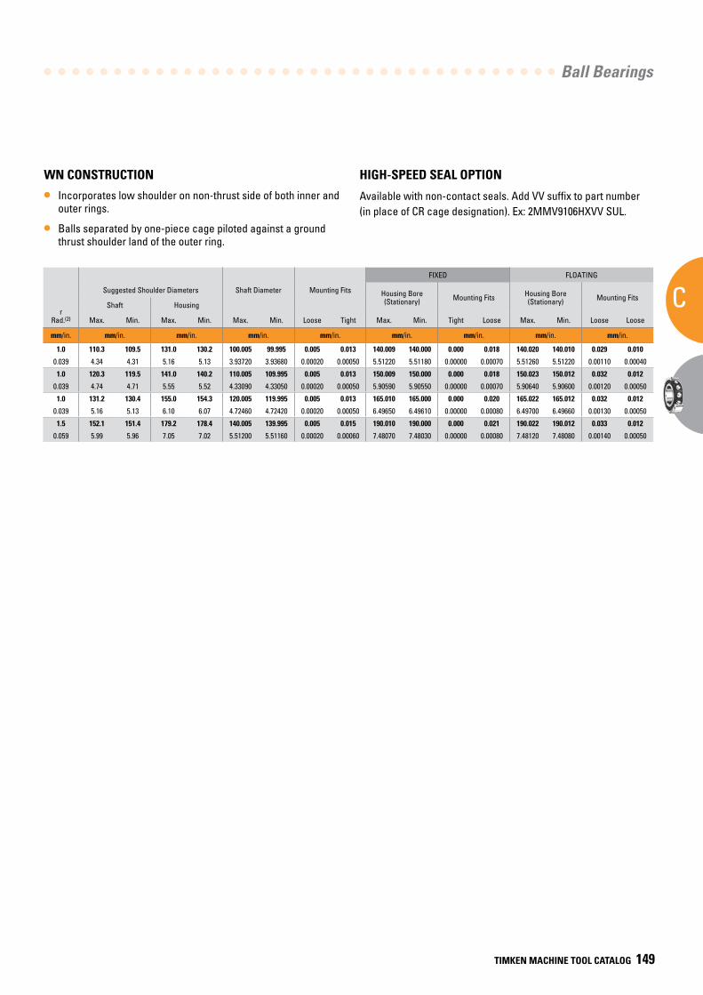
Ball Bearings
C
TIMKEN MACHINE TOOL CATALOG 149
BearingNumber15° C/2(3)
or25° E/3(4)
dBore
DO.D.
CWidth(1)
Ball Bearing
15° (C/2) LOAD RATINGS 25° (E/3) LOAD RATINGS
rRad.(2)
Suggested Shoulder Diameters Shaft Diameter Mounting Fits
FIXED FLOATING
Steel Ball Ceramic Ball Steel Ball Ceramic Ball Housing Bore (Stationary) Mounting Fits Housing Bore
(Stationary) Mounting Fits
CoStatic
CeDynamic
SpeedRating(Ng)
CoStatic
CeDynamic
SpeedRating(Ng)
CoStatic
CeDynamic
SpeedRating(Ng)
CoStatic
CeDynamic
SpeedRating(Ng)
Shaft Housing
Qty. x Dia. Wt. Max. Min. Max. Min. Max. Min. Loose Tight Max. Min. Tight Loose Max. Min. Loose Loose
mm/in. mm/in. kg/lbs. N/lbs. RPM N/lbs. RPM N/lbs. RPM N/lbs. RPM mm/in. mm/in. mm/in. mm/in. mm/in. mm/in. mm/in. mm/in. mm/in.
9320HX 100 140 20 29 x 10.3 0.850 24864 31403 11400 22151 31403 13680 23174 29535 9900 20639 29535 11800 1.0 110.3 109.5 131.0 130.2 100.005 99.995 0.005 0.013 140.009 140.000 0.000 0.018 140.020 140.010 0.029 0.010
HX71920 3.9370 5.5118 0.7874 29 x 13/32 1.80 5590 7060 11400 4980 7060 13680 5210 6640 10000 4640 6640 12000 0.039 4.34 4.31 5.16 5.13 3.93720 3.93680 0.00020 0.00050 5.51220 5.51180 0.00000 0.00070 5.51260 5.51220 0.00110 0.00040
9322HX 110 150 20 31 x 10.3 0.920 26377 32204 10500 23485 32204 12600 24597 30291 9500 21884 30291 11400 1.0 120.3 119.5 141.0 140.2 110.005 109.995 0.005 0.013 150.009 150.000 0.000 0.018 150.023 150.012 0.032 0.012
HX71922 4.3307 5.9055 0.7874 31 x 13/32 1.92 5930 7240 10500 5280 7240 12600 5530 6810 9500 4920 6810 11400 0.039 4.74 4.71 5.55 5.52 4.33090 4.33050 0.00020 0.00050 5.90590 5.90550 0.00000 0.00070 5.90640 5.90600 0.00120 0.00050
9324HX 120 165 22 30 x 11.9 1.240 34161 41277 9600 30424 41277 11520 31803 38831 8600 28334 38831 10320 1.0 131.2 130.4 155.0 154.3 120.005 119.995 0.005 0.013 165.010 165.000 0.000 0.020 165.022 165.012 0.032 0.012
HX71924 4.7244 6.4961 0.8661 30 x 15/32 2.60 7680 9280 9600 6840 9280 11520 7150 8730 8600 6370 8730 10320 0.039 5.16 5.13 6.10 6.07 4.72460 4.72420 0.00020 0.00050 6.49650 6.49610 0.00000 0.00080 6.49700 6.49660 0.00130 0.00050
9328HX 140 190 24 32 x 13.5 1.750 46704 53821 8300 41544 53821 9960 43501 50707 7500 38742 50707 9000 1.5 152.1 151.4 179.2 178.4 140.005 139.995 0.005 0.015 190.010 190.000 0.000 0.021 190.022 190.012 0.033 0.012
HX71928 5.5118 7.4803 0.9449 32 x 17/32 3.85 10500 12100 8300 9340 12100 9960 9780 11400 7500 8710 11400 9000 0.059 5.99 5.96 7.05 7.02 5.51200 5.51160 0.00020 0.00060 7.48070 7.48030 0.00000 0.00080 7.48120 7.48080 0.00140 0.00050
WN CONSTRUCTION
• Incorporates low shoulder on non-thrust side of both inner and outer rings.
• Balls separated by one-piece cage piloted against a ground thrust shoulder land of the outer ring.
HIGH-SPEED SEAL OPTION
Available with non-contact seals. Add VV suffix to part number (in place of CR cage designation). Ex: 2MMV9106HXVV SUL.
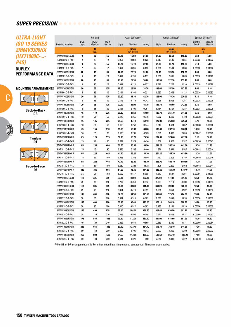
SUPER PRECISION
C
150 TIMKEN MACHINE TOOL CATALOG
ULTRA-LIGHT ISO 19 SERIES 2MMV9300HX (HX71900C-...-P4S)DUPLEX PERFORMANCE DATA
Preload Axial Stiffness(1) Radial Stiffness(1) Spacer Offsets(1)
Bearing NumberDUL Light
DUM Medium
DUH Heavy Light Medium Heavy Light Medium Heavy
Light to Med.
Med. to Heavy
N lbs.
N/µm 106 lbs./in.
N/µm 106 lbs./in.
µm in.
2MMV9300HXCR 9 25 55 10.20 15.60 21.00 61.00 88.50 110.80 5.60 5.60
HX71900C-T-P4S 2 6 12 0.058 0.089 0.120 0.349 0.506 0.634 0.00022 0.00022
2MMV9301HXCR 9 25 55 10.70 16.70 22.80 61.30 88.20 110.20 5.10 5.60
HX71901C-T-P4S 2 6 12 0.061 0.096 0.130 0.351 0.504 0.630 0.00020 0.00022
2MMV9302HXCR 20 45 85 17.00 22.70 31.00 96.40 120.90 150.90 4.60 6.60
HX71902C-T-P4S 5 10 20 0.097 0.130 0.177 0.551 0.691 0.863 0.00018 0.00026
2MMV9303HXCR 20 45 85 16.90 22.30 30.00 100.90 127.10 159.10 4.60 6.60
HX71903C-T-P4S 5 10 20 0.097 0.128 0.172 0.577 0.727 0.910 0.00018 0.00026
2MMV9304HXCR 20 65 135 18.20 28.50 38.70 109.60 157.90 197.30 7.60 8.10
HX71904C-T-P4S 5 15 30 0.104 0.163 0.221 0.627 0.903 1.128 0.00030 0.00032
2MMV9305HXCR 20 65 135 20.20 31.30 42.30 122.00 176.30 220.50 7.10 7.10
HX71905C-T-P4S 5 15 30 0.115 0.179 0.242 0.698 1.008 1.261 0.00028 0.00028
2MMV9306HXCR 20 65 135 22.00 33.90 45.70 133.70 193.60 242.60 6.10 6.60
HX71906C-T-P4S 5 15 30 0.126 0.194 0.261 0.764 1.107 1.387 0.00024 0.00026
2MMV9307HXCR 45 110 225 30.80 44.60 60.50 185.70 251.70 314.60 7.10 8.60
HX71907C-T-P4S 10 25 50 0.176 0.255 0.346 1.062 1.439 1.799 0.00028 0.00034
2MMV9308HXCR 45 135 265 29.50 45.10 60.10 177.90 259.60 325.70 9.70 10.20
HX71908C-T-P4S 10 30 60 0.169 0.258 0.344 1.017 1.484 1.862 0.00038 0.00040
2MMV9309HXCR 45 155 310 31.50 50.90 68.00 189.40 292.10 366.40 10.70 10.70
HX71909C-T-P4S 10 35 70 0.180 0.291 0.389 1.083 1.670 2.095 0.00042 0.00042
2MMV9310HXCR 65 175 355 38.70 56.70 75.90 232.60 324.60 407.00 9.10 10.70
HX71910C-T-P4S 15 40 80 0.221 0.324 0.434 1.330 1.856 2.327 0.00036 0.00042
2MMV9311HXCR 65 200 400 39.50 60.30 80.50 241.20 352.20 442.00 10.70 11.20
HX71911C-T-P4S 15 45 90 0.226 0.345 0.460 1.379 2.014 2.527 0.00042 0.00044
2MMV9312HXCR 65 225 445 41.70 66.20 88.30 254.10 385.70 483.90 11.70 11.70
HX71912C-T-P4S 15 50 100 0.238 0.378 0.505 1.453 2.205 2.767 0.00046 0.00046
2MMV9313HXCR 65 225 445 43.70 69.30 92.30 266.70 406.10 509.80 11.20 11.20
HX71913C-T-P4S 15 50 100 0.250 0.396 0.528 1.525 2.322 2.915 0.00044 0.00044
2MMV9314HXCR 110 335 665 51.00 78.10 104.50 316.60 461.20 578.40 13.70 14.70
HX71914C-T-P4S 25 75 150 0.292 0.447 0.598 1.810 2.637 3.307 0.00054 0.00058
2MMV9315HXCR 110 335 665 52.30 80.00 107.00 325.00 474.00 594.70 13.20 14.20
HX71915C-T-P4S 25 75 150 0.299 0.458 0.612 1.858 2.710 3.400 0.00052 0.00056
2MMV9316HXCR 110 335 665 54.90 83.80 111.80 341.20 499.00 626.50 12.70 13.70
HX71916C-T-P4S 25 75 150 0.314 0.479 0.639 1.951 2.853 3.582 0.00050 0.00054
2MMV9317HXCR 135 400 800 62.20 94.50 125.50 390.60 575.90 724.30 13.70 14.70
HX71917C-T-P4S 30 90 180 0.334 0.510 0.682 2.088 3.048 3.826 0.00056 0.00060
2MMV9318HXCR 135 400 800 59.40 90.40 120.20 373.10 548.10 688.90 14.20 15.20
HX71918C-T-P4S 30 90 180 0.340 0.517 0.687 2.133 3.134 3.939 0.00056 0.00060
2MMV9320HXCR 155 490 975 67.40 104.60 139.50 423.40 630.50 791.80 15.20 15.70
HX71920C-T-P4S 35 110 220 0.385 0.598 0.798 2.421 3.605 4.527 0.00060 0.00062
2MMV9322HXCR 175 535 1065 73.80 112.70 150.40 464.00 678.60 851.90 15.20 16.30
HX71922C-T-P4S 40 120 240 0.422 0.644 0.860 2.653 3.880 4.871 0.00060 0.00064
2MMV9324HXCR 225 665 1335 80.90 123.40 164.70 513.70 752.10 944.30 17.30 18.30
HX71924C-T-P4S 50 150 300 0.462 0.706 0.942 2.937 4.300 5.399 0.00068 0.00072
2MMV9328HXCR 265 800 1600 94.60 143.60 190.60 587.50 865.40 1088.20 17.80 19.30
HX71928C-T-P4S 60 180 360 0.541 0.821 1.090 3.359 4.948 6.222 0.00070 0.00076
(1) For DB or DF arrangements only. For other mounting arrangements, contact your Timken representative.
MOUNTING ARRANGEMENTS
Back-to-BackDB
TandemDT
Face-to-FaceDF
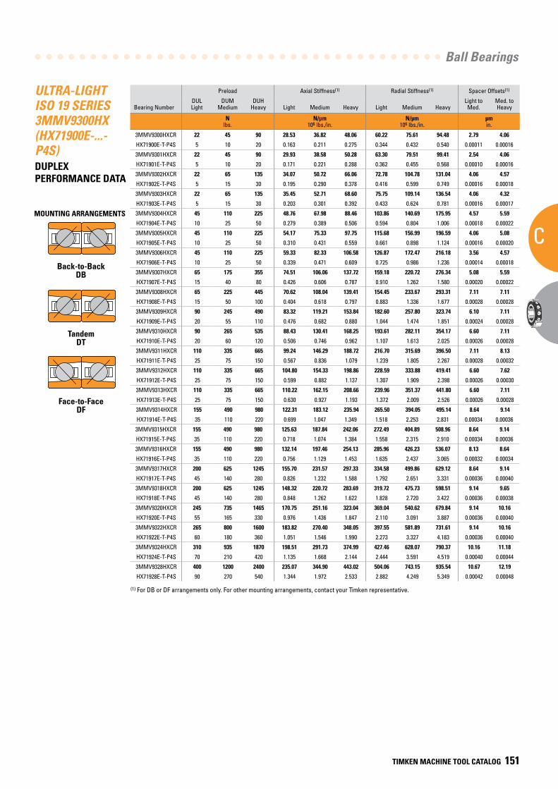
Ball Bearings
C
TIMKEN MACHINE TOOL CATALOG 151
ULTRA-LIGHT ISO 19 SERIES 3MMV9300HX (HX71900E-...-P4S)DUPLEX PERFORMANCE DATA
Preload Axial Stiffness(1) Radial Stiffness(1) Spacer Offsets(1)
Bearing NumberDUL Light
DUM Medium
DUH Heavy Light Medium Heavy Light Medium Heavy
Light to Med.
Med. to Heavy
N lbs.
N/µm 106 lbs./in.
N/µm 106 lbs./in.
µm in.
3MMV9300HXCR 22 45 90 28.53 36.82 48.06 60.22 75.61 94.48 2.79 4.06
HX71900E-T-P4S 5 10 20 0.163 0.211 0.275 0.344 0.432 0.540 0.00011 0.00016
3MMV9301HXCR 22 45 90 29.93 38.58 50.28 63.30 79.51 99.41 2.54 4.06
HX71901E-T-P4S 5 10 20 0.171 0.221 0.288 0.362 0.455 0.568 0.00010 0.00016
3MMV9302HXCR 22 65 135 34.07 50.72 66.06 72.78 104.78 131.04 4.06 4.57
HX71902E-T-P4S 5 15 30 0.195 0.290 0.378 0.416 0.599 0.749 0.00016 0.00018
3MMV9303HXCR 22 65 135 35.45 52.71 68.60 75.75 109.14 136.54 4.06 4.32
HX71903E-T-P4S 5 15 30 0.203 0.301 0.392 0.433 0.624 0.781 0.00016 0.00017
3MMV9304HXCR 45 110 225 48.76 67.98 88.46 103.86 140.69 175.95 4.57 5.59
HX71904E-T-P4S 10 25 50 0.279 0.389 0.506 0.594 0.804 1.006 0.00018 0.00022
3MMV9305HXCR 45 110 225 54.17 75.33 97.75 115.68 156.99 196.59 4.06 5.08
HX71905E-T-P4S 10 25 50 0.310 0.431 0.559 0.661 0.898 1.124 0.00016 0.00020
3MMV9306HXCR 45 110 225 59.33 82.33 106.58 126.87 172.47 216.18 3.56 4.57
HX71906E-T-P4S 10 25 50 0.339 0.471 0.609 0.725 0.986 1.236 0.00014 0.00018
3MMV9307HXCR 65 175 355 74.51 106.06 137.72 159.18 220.72 276.34 5.08 5.59
HX71907E-T-P4S 15 40 80 0.426 0.606 0.787 0.910 1.262 1.580 0.00020 0.00022
3MMV9308HXCR 65 225 445 70.62 108.04 139.41 154.45 233.67 293.31 7.11 7.11
HX71908E-T-P4S 15 50 100 0.404 0.618 0.797 0.883 1.336 1.677 0.00028 0.00028
3MMV9309HXCR 90 245 490 83.32 119.21 153.84 182.60 257.80 323.74 6.10 7.11
HX71909E-T-P4S 20 55 110 0.476 0.682 0.880 1.044 1.474 1.851 0.00024 0.00028
3MMV9310HXCR 90 265 535 88.43 130.41 168.25 193.61 282.11 354.17 6.60 7.11
HX71910E-T-P4S 20 60 120 0.506 0.746 0.962 1.107 1.613 2.025 0.00026 0.00028
3MMV9311HXCR 110 335 665 99.24 146.29 188.72 216.70 315.69 396.50 7.11 8.13
HX71911E-T-P4S 25 75 150 0.567 0.836 1.079 1.239 1.805 2.267 0.00028 0.00032
3MMV9312HXCR 110 335 665 104.80 154.33 198.86 228.59 333.88 419.41 6.60 7.62
HX71912E-T-P4S 25 75 150 0.599 0.882 1.137 1.307 1.909 2.398 0.00026 0.00030
3MMV9313HXCR 110 335 665 110.22 162.15 208.66 239.96 351.37 441.80 6.60 7.11
HX71913E-T-P4S 25 75 150 0.630 0.927 1.193 1.372 2.009 2.526 0.00026 0.00028
3MMV9314HXCR 155 490 980 122.31 183.12 235.94 265.50 394.05 495.14 8.64 9.14
HX71914E-T-P4S 35 110 220 0.699 1.047 1.349 1.518 2.253 2.831 0.00034 0.00036
3MMV9315HXCR 155 490 980 125.63 187.84 242.06 272.49 404.89 508.96 8.64 9.14
HX71915E-T-P4S 35 110 220 0.718 1.074 1.384 1.558 2.315 2.910 0.00034 0.00036
3MMV9316HXCR 155 490 980 132.14 197.46 254.13 285.96 426.23 536.07 8.13 8.64
HX71916E-T-P4S 35 110 220 0.756 1.129 1.453 1.635 2.437 3.065 0.00032 0.00034
3MMV9317HXCR 200 625 1245 155.70 231.57 297.33 334.58 499.86 629.12 8.64 9.14
HX71917E-T-P4S 45 140 280 0.826 1.232 1.588 1.792 2.651 3.331 0.00036 0.00040
3MMV9318HXCR 200 625 1245 148.32 220.72 283.69 319.72 475.73 598.51 9.14 9.65
HX71918E-T-P4S 45 140 280 0.848 1.262 1.622 1.828 2.720 3.422 0.00036 0.00038
3MMV9320HXCR 245 735 1465 170.75 251.16 323.04 369.04 540.62 679.84 9.14 10.16
HX71920E-T-P4S 55 165 330 0.976 1.436 1.847 2.110 3.091 3.887 0.00036 0.00040
3MMV9322HXCR 265 800 1600 183.82 270.40 348.05 397.55 581.89 731.61 9.14 10.16
HX71922E-T-P4S 60 180 360 1.051 1.546 1.990 2.273 3.327 4.183 0.00036 0.00040
3MMV9324HXCR 310 935 1870 198.51 291.73 374.99 427.46 628.07 790.37 10.16 11.18
HX71924E-T-P4S 70 210 420 1.135 1.668 2.144 2.444 3.591 4.519 0.00040 0.00044
3MMV9328HXCR 400 1200 2400 235.07 344.90 443.02 504.06 743.15 935.54 10.67 12.19
HX71928E-T-P4S 90 270 540 1.344 1.972 2.533 2.882 4.249 5.349 0.00042 0.00048
(1) For DB or DF arrangements only. For other mounting arrangements, contact your Timken representative.
MOUNTING ARRANGEMENTS
Back-to-BackDB
TandemDT
Face-to-FaceDF
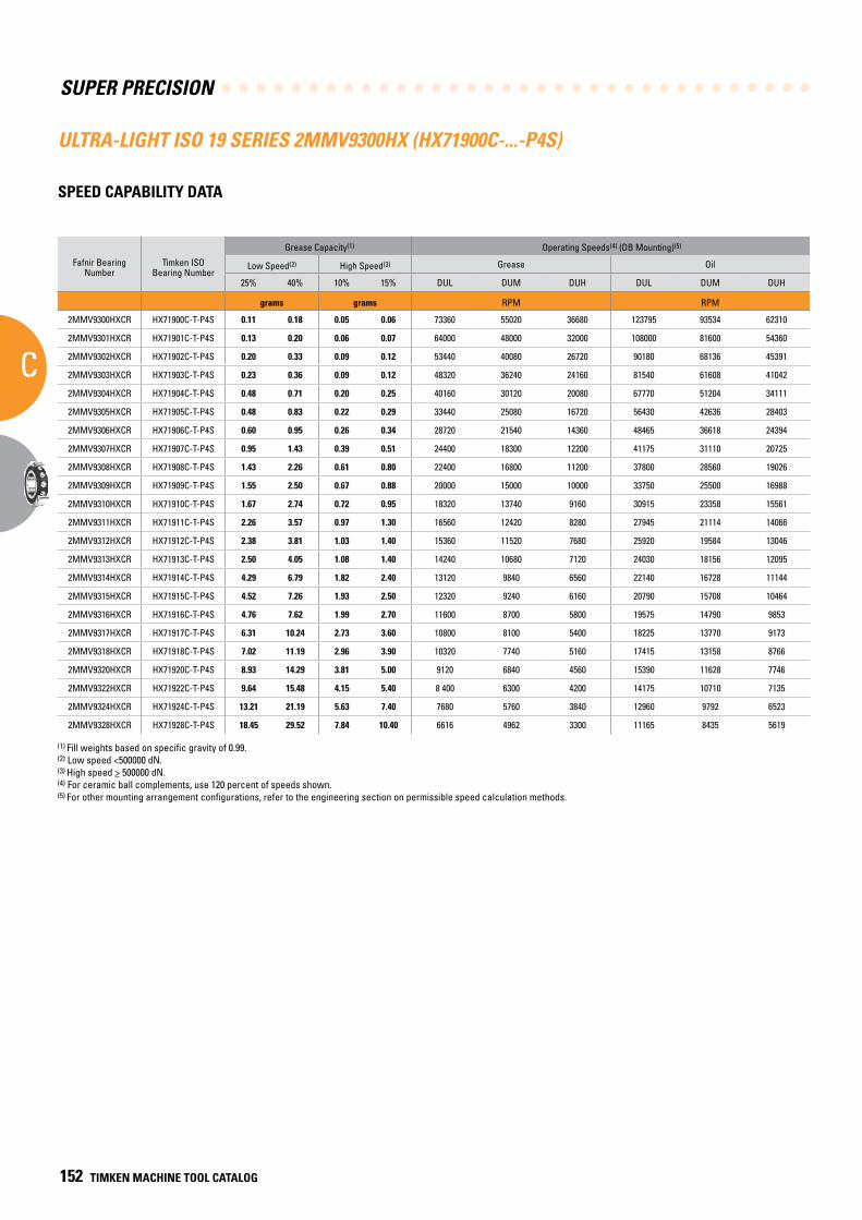
SUPER PRECISION
C
152 TIMKEN MACHINE TOOL CATALOG
ULTRA-LIGHT ISO 19 SERIES 2MMV9300HX (HX71900C-...-P4S)
SPEED CAPABILITY DATA
Fafnir Bearing Number
Timken ISO Bearing Number
Grease Capacity(1) Operating Speeds(4) (DB Mounting)(5)
Low Speed(2) High Speed(3) Grease Oil
25% 40% 10% 15% DUL DUM DUH DUL DUM DUH
grams grams RPM RPM
2MMV9300HXCR HX71900C-T-P4S 0.11 0.18 0.05 0.06 73360 55020 36680 123795 93534 62310
2MMV9301HXCR HX71901C-T-P4S 0.13 0.20 0.06 0.07 64000 48000 32000 108000 81600 54360
2MMV9302HXCR HX71902C-T-P4S 0.20 0.33 0.09 0.12 53440 40080 26720 90180 68136 45391
2MMV9303HXCR HX71903C-T-P4S 0.23 0.36 0.09 0.12 48320 36240 24160 81540 61608 41042
2MMV9304HXCR HX71904C-T-P4S 0.48 0.71 0.20 0.25 40160 30120 20080 67770 51204 34111
2MMV9305HXCR HX71905C-T-P4S 0.48 0.83 0.22 0.29 33440 25080 16720 56430 42636 28403
2MMV9306HXCR HX71906C-T-P4S 0.60 0.95 0.26 0.34 28720 21540 14360 48465 36618 24394
2MMV9307HXCR HX71907C-T-P4S 0.95 1.43 0.39 0.51 24400 18300 12200 41175 31110 20725
2MMV9308HXCR HX71908C-T-P4S 1.43 2.26 0.61 0.80 22400 16800 11200 37800 28560 19026
2MMV9309HXCR HX71909C-T-P4S 1.55 2.50 0.67 0.88 20000 15000 10000 33750 25500 16988
2MMV9310HXCR HX71910C-T-P4S 1.67 2.74 0.72 0.95 18320 13740 9160 30915 23358 15561
2MMV9311HXCR HX71911C-T-P4S 2.26 3.57 0.97 1.30 16560 12420 8280 27945 21114 14066
2MMV9312HXCR HX71912C-T-P4S 2.38 3.81 1.03 1.40 15360 11520 7680 25920 19584 13046
2MMV9313HXCR HX71913C-T-P4S 2.50 4.05 1.08 1.40 14240 10680 7120 24030 18156 12095
2MMV9314HXCR HX71914C-T-P4S 4.29 6.79 1.82 2.40 13120 9840 6560 22140 16728 11144
2MMV9315HXCR HX71915C-T-P4S 4.52 7.26 1.93 2.50 12320 9240 6160 20790 15708 10464
2MMV9316HXCR HX71916C-T-P4S 4.76 7.62 1.99 2.70 11600 8700 5800 19575 14790 9853
2MMV9317HXCR HX71917C-T-P4S 6.31 10.24 2.73 3.60 10800 8100 5400 18225 13770 9173
2MMV9318HXCR HX71918C-T-P4S 7.02 11.19 2.96 3.90 10320 7740 5160 17415 13158 8766
2MMV9320HXCR HX71920C-T-P4S 8.93 14.29 3.81 5.00 9120 6840 4560 15390 11628 7746
2MMV9322HXCR HX71922C-T-P4S 9.64 15.48 4.15 5.40 8 400 6300 4200 14175 10710 7135
2MMV9324HXCR HX71924C-T-P4S 13.21 21.19 5.63 7.40 7680 5760 3840 12960 9792 6523
2MMV9328HXCR HX71928C-T-P4S 18.45 29.52 7.84 10.40 6616 4962 3300 11165 8435 5619
(1) Fill weights based on specific gravity of 0.99.(2) Low speed <500000 dN.(3) High speed > 500000 dN.(4) For ceramic ball complements, use 120 percent of speeds shown.(5) For other mounting arrangement configurations, refer to the engineering section on permissible speed calculation methods.
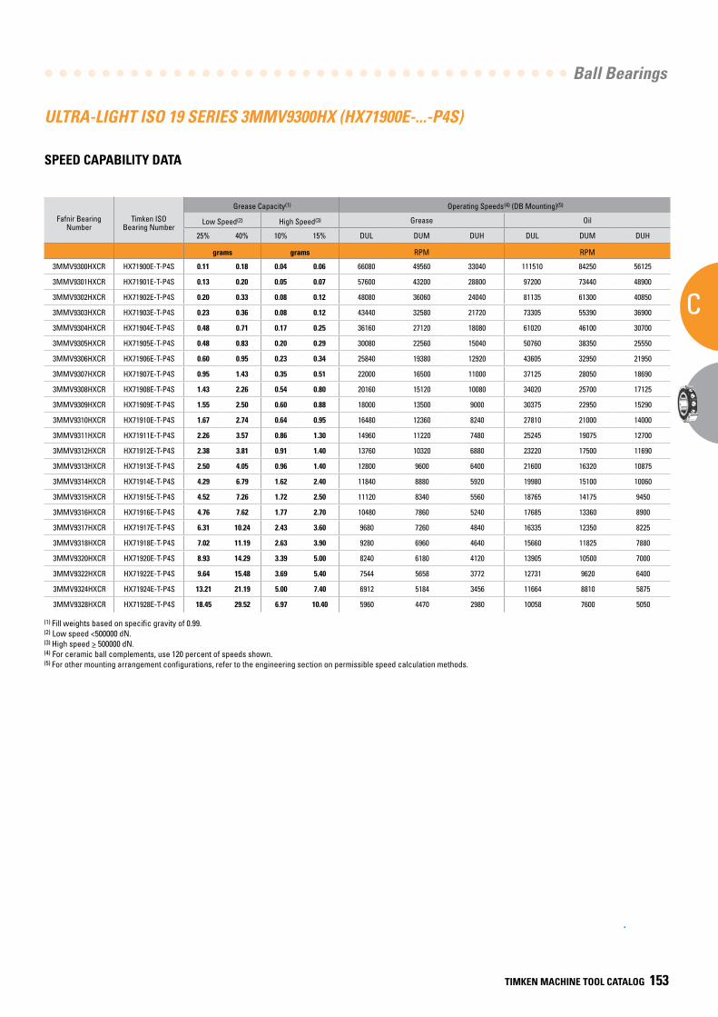
Ball Bearings
C
TIMKEN MACHINE TOOL CATALOG 153
ULTRA-LIGHT ISO 19 SERIES 3MMV9300HX (HX71900E-...-P4S)
SPEED CAPABILITY DATA
Fafnir Bearing Number
Timken ISO Bearing Number
Grease Capacity(1) Operating Speeds(4) (DB Mounting)(5)
Low Speed(2) High Speed(3) Grease Oil
25% 40% 10% 15% DUL DUM DUH DUL DUM DUH
grams grams RPM RPM
3MMV9300HXCR HX71900E-T-P4S 0.11 0.18 0.04 0.06 66080 49560 33040 111510 84250 56125
3MMV9301HXCR HX71901E-T-P4S 0.13 0.20 0.05 0.07 57600 43200 28800 97200 73440 48900
3MMV9302HXCR HX71902E-T-P4S 0.20 0.33 0.08 0.12 48080 36060 24040 81135 61300 40850
3MMV9303HXCR HX71903E-T-P4S 0.23 0.36 0.08 0.12 43440 32580 21720 73305 55390 36900
3MMV9304HXCR HX71904E-T-P4S 0.48 0.71 0.17 0.25 36160 27120 18080 61020 46100 30700
3MMV9305HXCR HX71905E-T-P4S 0.48 0.83 0.20 0.29 30080 22560 15040 50760 38350 25550
3MMV9306HXCR HX71906E-T-P4S 0.60 0.95 0.23 0.34 25840 19380 12920 43605 32950 21950
3MMV9307HXCR HX71907E-T-P4S 0.95 1.43 0.35 0.51 22000 16500 11000 37125 28050 18690
3MMV9308HXCR HX71908E-T-P4S 1.43 2.26 0.54 0.80 20160 15120 10080 34020 25700 17125
3MMV9309HXCR HX71909E-T-P4S 1.55 2.50 0.60 0.88 18000 13500 9000 30375 22950 15290
3MMV9310HXCR HX71910E-T-P4S 1.67 2.74 0.64 0.95 16480 12360 8240 27810 21000 14000
3MMV9311HXCR HX71911E-T-P4S 2.26 3.57 0.86 1.30 14960 11220 7480 25245 19075 12700
3MMV9312HXCR HX71912E-T-P4S 2.38 3.81 0.91 1.40 13760 10320 6880 23220 17500 11690
3MMV9313HXCR HX71913E-T-P4S 2.50 4.05 0.96 1.40 12800 9600 6400 21600 16320 10875
3MMV9314HXCR HX71914E-T-P4S 4.29 6.79 1.62 2.40 11840 8880 5920 19980 15100 10060
3MMV9315HXCR HX71915E-T-P4S 4.52 7.26 1.72 2.50 11120 8340 5560 18765 14175 9450
3MMV9316HXCR HX71916E-T-P4S 4.76 7.62 1.77 2.70 10480 7860 5240 17685 13360 8900
3MMV9317HXCR HX71917E-T-P4S 6.31 10.24 2.43 3.60 9680 7260 4840 16335 12350 8225
3MMV9318HXCR HX71918E-T-P4S 7.02 11.19 2.63 3.90 9280 6960 4640 15660 11825 7880
3MMV9320HXCR HX71920E-T-P4S 8.93 14.29 3.39 5.00 8240 6180 4120 13905 10500 7000
3MMV9322HXCR HX71922E-T-P4S 9.64 15.48 3.69 5.40 7544 5658 3772 12731 9620 6400
3MMV9324HXCR HX71924E-T-P4S 13.21 21.19 5.00 7.40 6912 5184 3456 11664 8810 5875
3MMV9328HXCR HX71928E-T-P4S 18.45 29.52 6.97 10.40 5960 4470 2980 10058 7600 5050
(1) Fill weights based on specific gravity of 0.99.(2) Low speed <500000 dN.(3) High speed > 500000 dN.(4) For ceramic ball complements, use 120 percent of speeds shown.(5) For other mounting arrangement configurations, refer to the engineering section on permissible speed calculation methods.
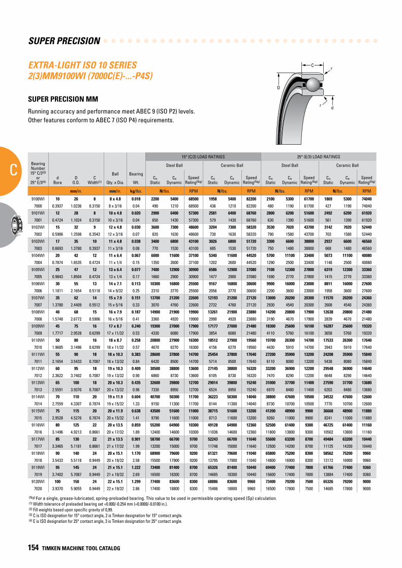
SUPER PRECISION
C
154 TIMKEN MACHINE TOOL CATALOG
C
D
r
dr
EXTRA-LIGHT ISO 10 SERIES 2(3)MM9100WI (7000C(E)-...-P4S)
SUPER PRECISION MM
Running accuracy and performance meet ABEC 9 (ISO P2) levels. Other features conform to ABEC 7 (ISO P4) requirements.
BearingNumber15° C/2(3)
or25° E/3(4)
dBore
DO.D.
CWidth(1)
Ball Bearing
15° (C/2) LOAD RATINGS 25° (E/3) LOAD RATINGS
rRad.(2)
Suggested Shoulder Diameters Shaft Diameter Mounting Fits
FIXED FLOATING
Steel Ball Ceramic Ball Steel Ball Ceramic Ball Housing Bore (Stationary) Mounting Fits Housing Bore
(Stationary) Mounting Fits
CoStatic
CeDynamic
SpeedRating(Ng)
CoStatic
CeDynamic
SpeedRating(Ng)
CoStatic
CeDynamic
SpeedRating(Ng)
CoStatic
CeDynamic
SpeedRating(Ng)
Shaft Housing
Qty. x Dia. Wt. Max. Min. Max. Min. Max. Min. Loose Tight Max. Min. Tight Loose Max. Min. Loose Loose
mm/in. mm/in. kg/lbs. N/lbs. RPM N/lbs. RPM N/lbs. RPM N/lbs. RPM mm/in. mm/in. mm/in. mm/in. mm/in. mm/in. mm/in. mm/in. mm/in.
9100WI 10 26 8 8 x 4.8 0.018 2200 5400 68500 1958 5400 82200 2100 5300 61700 1869 5300 74040 0.3 13.6 13.3 23.2 23.0 10.000 9.995 0.005 0.004 26.005 26.000 0.000 0.010 26.010 26.005 0.015 0.005
7000 0.3937 1.0236 0.3150 8 x 3/16 0.04 490 1210 68500 436 1210 82200 480 1190 61700 427 1190 74040 0.012 0.54 0.53 0.92 0.91 0.39370 0.39350 0.00020 0.00015 1.02380 1.02360 0.00000 0.00040 1.02400 1.02380 0.00060 0.00020
9101WI 12 28 8 10 x 4.8 0.020 2900 6400 57300 2581 6400 68760 2800 6200 51600 2492 6200 61920 0.3 16.1 15.9 25.5 25.3 12.000 11.995 0.005 0.004 28.005 28.000 0.000 0.010 28.010 28.005 0.015 0.005
7001 0.4724 1.1024 0.3150 10 x 3/16 0.04 650 1430 57300 579 1430 68760 630 1390 51600 561 1390 61920 0.012 0.64 0.63 1.01 1.00 0.47240 0.47220 0.00020 0.00015 1.10260 1.10240 0.00000 0.00040 1.10280 1.10260 0.00060 0.00020
9102WI 15 32 9 12 x 4.8 0.030 3600 7300 48600 3204 7300 58320 3530 7020 43700 3142 7020 52440 0.3 19.2 18.9 28.6 28.3 15.000 14.995 0.005 0.004 32.005 32.000 0.000 0.011 32.010 32.005 0.016 0.005
7002 0.5906 1.2598 0.3543 12 x 3/16 0.07 820 1630 48600 730 1630 58320 790 1580 43700 703 1580 52440 0.012 0.76 0.75 1.13 1.12 0.59060 0.59040 0.00020 0.00015 1.26000 1.25980 0.00000 0.00045 1.26020 1.26000 0.00070 0.00020
9103WI 17 35 10 11 x 4.8 0.038 3400 6800 43100 3026 6800 51720 3300 6600 38800 2937 6600 46560 0.3 21.7 21.5 31.1 30.9 17.000 16.995 0.005 0.004 35.006 35.000 0.000 0.012 35.010 35.005 0.016 0.005
7003 0.6693 1.3780 0.3937 11 x 3/16 0.08 770 1530 43100 685 1530 51720 750 1480 38800 668 1480 46560 0.012 0.86 0.85 1.23 1.22 0.66930 0.66910 0.00020 0.00015 1.37830 1.37800 0.00000 0.00050 1.37840 1.37820 0.00070 0.00020
9104WI 20 42 12 11 x 6.4 0.067 6000 11600 37100 5340 11600 44520 5700 11100 33400 5073 11100 40080 0.6 25.0 24.8 37.7 37.5 20.000 19.995 0.005 0.005 42.006 42.000 0.000 0.012 42.010 42.005 0.016 0.005
7004 0.7874 1.6535 0.4724 11 x 1/4 0.15 1350 2600 37100 1202 2600 44520 1290 2500 33400 1148 2500 40080 0.024 0.99 0.98 1.49 1.48 0.78740 0.78720 0.00020 0.00020 1.65380 1.65350 0.00000 0.00050 1.65390 1.65370 0.00070 0.00020
9105WI 25 47 12 13 x 6.4 0.077 7400 12900 30900 6586 12900 37080 7100 12300 27800 6319 12300 33360 0.6 30.1 29.9 42.6 42.3 25.000 24.995 0.005 0.005 47.006 47.000 0.000 0.012 47.012 47.007 0.018 0.007
7005 0.9843 1.8504 0.4724 13 x 1/4 0.17 1660 2900 30900 1477 2900 37080 1590 2770 27800 1415 2770 33360 0.024 1.19 1.18 1.68 1.67 0.98430 0.98410 0.00020 0.00020 1.85070 1.85040 0.00000 0.00050 1.85090 1.85070 0.00080 0.00030
9106WI 30 55 13 14 x 7.1 0.113 10300 16800 25500 9167 16800 30600 9900 16000 23000 8811 16000 27600 1.0 36.2 35.9 50.7 50.4 30.000 29.995 0.005 0.005 55.008 55.000 0.000 0.015 55.012 55.007 0.019 0.007
7006 1.1811 2.1654 0.5118 14 x 9/32 0.25 2310 3770 25500 2056 3770 30600 2200 3600 23000 1958 3600 27600 0.039 1.43 1.42 2.00 1.99 1.18110 1.18090 0.00020 0.00020 2.16570 2.16540 0.00000 0.00060 2.16590 2.16570 0.00080 0.00030
9107WI 35 62 14 15 x 7.9 0.151 13700 21200 22600 12193 21200 27120 13000 20200 20300 11570 20200 24360 1.0 41.2 40.6 56.6 56.1 35.000 34.995 0.005 0.006 62.008 62.000 0.000 0.015 62.012 62.007 0.019 0.007
7007 1.3780 2.4409 0.5512 15 x 5/16 0.33 3070 4760 22600 2732 4760 27120 2930 4540 20300 2608 4540 24360 0.039 1.62 1.60 2.23 2.21 1.37800 1.37780 0.00020 0.00025 2.44120 2.44090 0.00000 0.00060 2.44140 2.44120 0.00080 0.00030
9108WI 40 68 15 16 x 7.9 0.187 14900 21900 19900 13261 21900 23880 14200 20800 17900 12638 20800 21480 1.0 46.2 45.7 62.2 61.7 40.000 39.995 0.005 0.006 68.008 68.000 0.000 0.015 68.012 68.007 0.019 0.007
7008 1.5748 2.6772 0.5906 16 x 5/16 0.41 3360 4920 19900 2990 4920 23880 3190 4670 17900 2839 4670 21480 0.039 1.82 1.80 2.45 2.43 1.57480 1.57460 0.00020 0.00025 2.67750 2.67720 0.00000 0.00060 2.67770 2.67750 0.00080 0.00030
9109WI 45 75 16 17 x 8.7 0.240 19300 27000 17900 17177 27000 21480 18300 25600 16100 16287 25600 19320 1.0 51.8 51.3 69.3 68.8 45.000 44.995 0.005 0.006 75.008 75.000 0.000 0.015 75.014 75.009 0.022 0.009
7009 1.7717 2.9528 0.6299 17 x 11/32 0.53 4330 6080 17900 3854 6080 21480 4110 5760 16100 3658 5760 19320 0.039 2.04 2.02 2.73 2.71 1.77170 1.77150 0.00020 0.00025 2.95310 2.95280 0.00000 0.00060 2.95330 2.95310 0.00080 0.00030
9110WI 50 80 16 18 x 8.7 0.258 20800 27900 16300 18512 27900 19560 19700 26300 14700 17533 26300 17640 1.0 56.6 56.1 74.2 73.7 50.000 49.995 0.005 0.006 80.008 80.000 0.000 0.015 80.012 80.008 0.020 0.008
7010 1.9685 3.1496 0.6299 18 x 11/32 0.57 4670 6270 16300 4156 6270 19560 4430 5910 14700 3943 5910 17640 0.039 2.23 2.21 2.92 2.90 1.96850 1.96830 0.00020 0.00025 3.14990 3.14960 0.00000 0.00060 3.15010 3.14990 0.00080 0.00030
9111WI 55 90 18 18 x 10.3 0.383 28600 37800 14700 25454 37800 17640 27200 35900 13200 24208 35900 15840 1.0 62.7 62.2 83.3 82.8 55.000 54.995 0.005 0.007 90.008 90.000 0.000 0.016 90.015 90.007 0.023 0.007
7011 2.1654 3.5433 0.7087 18 x 13/32 0.84 6420 8500 14700 5714 8500 17640 6110 8080 13200 5438 8080 15840 0.039 2.47 2.45 3.28 3.26 2.16540 2.16520 0.00020 0.00030 3.54360 3.54330 0.00000 0.00060 3.54390 3.54360 0.00090 0.00030
9112WI 60 95 18 19 x 10.3 0.409 30500 38800 13600 27145 38800 16320 33200 36900 12200 29548 36900 14640 1.0 67.8 67.3 88.1 87.6 60.000 59.995 0.005 0.007 95.008 95.000 0.000 0.016 95.016 95.009 0.024 0.009
7012 2.3622 3.7402 0.7087 19 x 13/32 0.90 6860 8730 13600 6105 8730 16320 7470 8290 12200 6648 8290 14640 0.039 2.67 2.65 3.47 3.45 2.36220 2.36200 0.00020 0.00030 3.74050 3.74020 0.00000 0.00060 3.74080 3.74050 0.00090 0.00030
9113WI 65 100 18 20 x 10.3 0.435 32600 39800 12700 29014 39800 15240 31000 37700 11400 27590 37700 13680 1.0 72.6 72.1 93.2 92.7 65.000 64.995 0.005 0.007 100.008 100.000 0.000 0.016 100.018 100.010 0.025 0.010
7013 2.5591 3.9370 0.7087 20 x 13/32 0.96 7330 8950 12700 6524 8950 15240 6970 8480 11400 6203 8480 13680 0.039 2.86 2.84 3.67 3.65 2.55910 2.55890 0.00020 0.00030 3.93730 3.93700 0.00000 0.00060 3.93770 3.93740 0.00100 0.00040
9114WI 70 110 20 19 x 11.9 0.604 40700 50300 11700 36223 50300 14040 38800 47600 10500 34532 47600 12600 1.0 78.2 77.7 102.4 101.9 70.000 69.995 0.005 0.007 110.008 110.000 0.000 0.016 110.018 110.010 0.025 0.010
7014 2.7559 4.3307 0.7874 19 x 15/32 1.33 9150 11300 11700 8144 11300 14040 8730 10700 10500 7770 10700 12600 0.039 3.08 3.06 4.03 4.01 2.75590 2.75570 0.00020 0.00030 4.33100 4.33070 0.00000 0.00060 4.33140 4.33110 0.00100 0.00040
9115WI 75 115 20 20 x 11.9 0.638 43500 51600 11000 38715 51600 13200 41200 48900 9900 36668 48900 11880 1.0 83.4 82.7 107.3 106.6 75.005 74.995 0.005 0.012 115.008 115.000 0.000 0.016 115.019 115.011 0.026 0.010
7015 2.9528 4.5276 0.7874 20 x 15/32 1.41 9790 11600 11000 8713 11600 13200 9260 11000 9900 8241 11000 11880 0.039 3.29 3.26 4.23 4.20 2.95300 2.95260 0.00020 0.00050 4.52790 4.52760 0.00000 0.00060 4.52830 4.52800 0.00100 0.00040
9116WI 80 125 22 20 x 13.5 0.859 55200 64900 10300 49128 64900 12360 52500 61400 9300 46725 61400 11160 1.0 89.3 88.5 116.5 115.7 80.005 79.995 0.005 0.012 125.008 125.000 0.000 0.017 125.021 125.011 0.030 0.011
7016 3.1496 4.9213 0.8661 20 x 17/32 1.89 12400 14600 10300 11036 14600 12360 11800 13800 9300 10502 13800 11160 0.039 3.52 3.49 4.59 4.56 3.14980 3.14940 0.00020 0.00050 4.92160 4.92130 0.00000 0.00070 4.92210 4.92170 0.00120 0.00040
9117WI 85 130 22 21 x 13.5 0.901 58700 66700 9700 52243 66700 11640 55600 63200 8700 49484 63200 10440 1.0 94.9 94.1 122.1 121.3 85.005 84.995 0.005 0.012 130.009 130.000 0.000 0.018 130.020 130.010 0.029 0.010
7017 3.3465 5.1181 0.8661 21 x 17/32 1.99 13200 15000 9700 11748 15000 11640 12500 14200 8700 11125 14200 10440 0.039 3.74 3.71 4.81 4.78 3.34670 3.34630 0.00020 0.00050 5.11850 5.11810 0.00000 0.00070 5.11890 5.11850 0.00110 0.00040
9118WI 90 140 24 20 x 15.1 1.170 68900 79600 9200 61321 79600 11040 65800 75200 8300 58562 75200 9960 1.5 100.5 99.7 130.9 130.2 90.005 89.995 0.005 0.013 140.009 140.000 0.000 0.018 140.020 140.010 0.029 0.010
7018 3.5433 5.5118 0.9449 20 x 19/32 2.58 15500 17900 9200 13795 17900 11040 14800 16900 8300 13172 16900 9960 0.059 3.96 3.93 5.16 5.13 3.54350 3.54310 0.00020 0.00050 5.51220 5.51180 0.00000 0.00070 5.51260 5.51220 0.00110 0.00040
9119WI 95 145 24 21 x 15.1 1.222 73400 81400 8700 65326 81400 10440 69400 77400 7800 61766 77400 9360 1.5 105.5 104.8 135.8 135.0 95.005 94.995 0.005 0.013 145.009 145.000 0.000 0.018 145.021 145.011 0.030 0.011
7019 3.7402 5.7087 0.9449 21 x 19/32 2.69 16500 18300 8700 14685 18300 10440 15600 17400 7800 13884 17400 9360 0.059 4.16 4.13 5.35 5.32 3.74040 3.74000 0.00020 0.00050 5.70910 5.70870 0.00000 0.00070 5.70950 5.70910 0.00110 0.00040
9120WI 100 150 24 22 x 15.1 1.299 77400 83600 8300 68886 83600 9960 73400 79200 7500 65326 79200 9000 1.5 110.6 109.9 140.8 140.1 100.005 99.995 0.005 0.013 150.009 150.000 0.000 0.018 150.023 150.012 0.032 0.012
7020 3.9370 5.9055 0.9449 22 x 19/32 2.86 17400 18800 8300 15486 18800 9960 16500 17800 7500 14685 17800 9000 0.059 4.36 4.33 5.55 5.52 3.93720 3.93680 0.00020 0.00050 5.90590 5.90550 0.00000 0.00070 5.90640 5.90600 0.00120 0.00050
(Ng) For a single, grease-lubricated, spring-preloaded bearing. This value to be used in permissible operating speed (Sp) calculation.(1) Width tolerance of preloaded bearing set +0.000/-0.254 mm (+0.0000/-0.0100 in.).(2) Fill weights based upon specific gravity of 0,99.(3) C is ISO designation for 15° contact angle, 2 is Timken designation for 15° contact angle.(4) E is ISO designation for 25° contact angle, 3 is Timken designation for 25° contact angle.
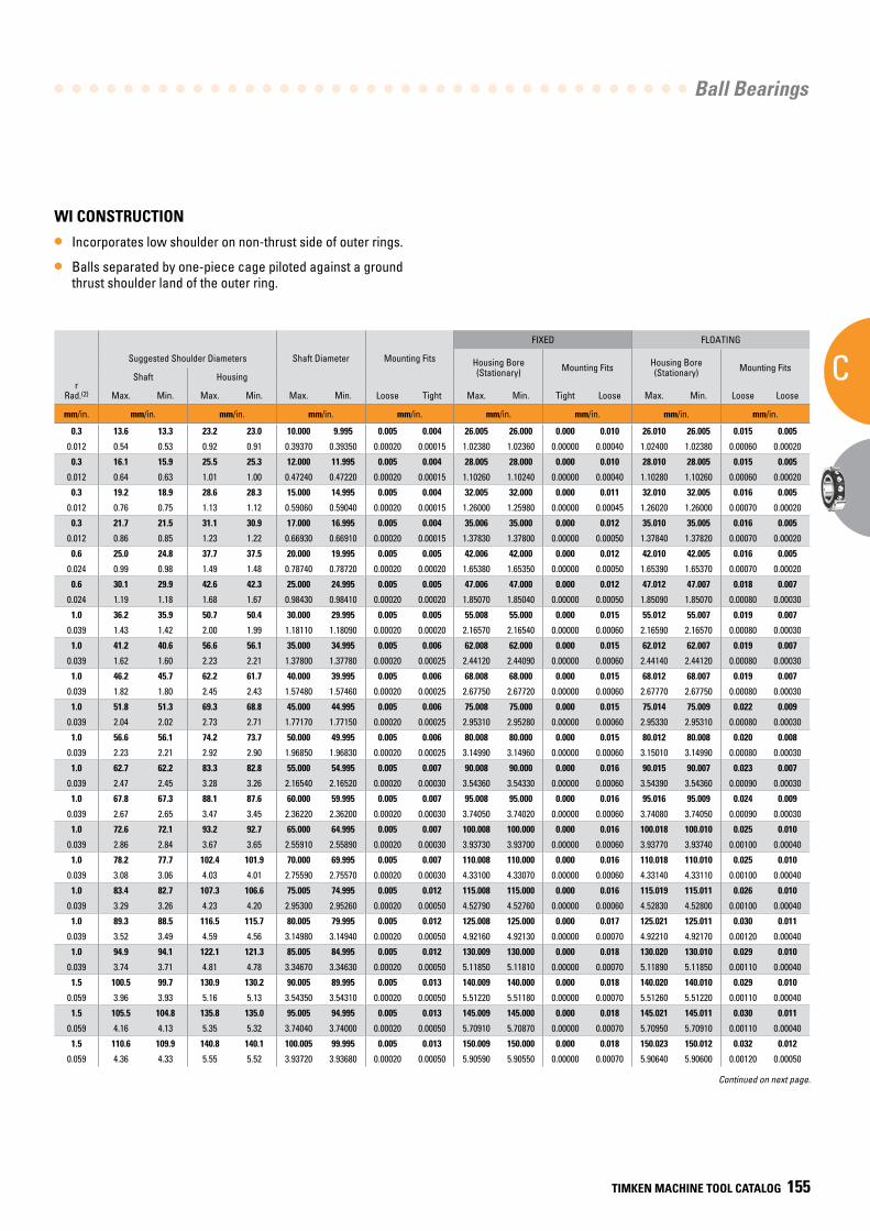
Ball Bearings
C
TIMKEN MACHINE TOOL CATALOG 155
WI CONSTRUCTION
• Incorporates low shoulder on non-thrust side of outer rings.
• Balls separated by one-piece cage piloted against a ground thrust shoulder land of the outer ring.
BearingNumber15° C/2(3)
or25° E/3(4)
dBore
DO.D.
CWidth(1)
Ball Bearing
15° (C/2) LOAD RATINGS 25° (E/3) LOAD RATINGS
rRad.(2)
Suggested Shoulder Diameters Shaft Diameter Mounting Fits
FIXED FLOATING
Steel Ball Ceramic Ball Steel Ball Ceramic Ball Housing Bore (Stationary) Mounting Fits Housing Bore
(Stationary) Mounting Fits
CoStatic
CeDynamic
SpeedRating(Ng)
CoStatic
CeDynamic
SpeedRating(Ng)
CoStatic
CeDynamic
SpeedRating(Ng)
CoStatic
CeDynamic
SpeedRating(Ng)
Shaft Housing
Qty. x Dia. Wt. Max. Min. Max. Min. Max. Min. Loose Tight Max. Min. Tight Loose Max. Min. Loose Loose
mm/in. mm/in. kg/lbs. N/lbs. RPM N/lbs. RPM N/lbs. RPM N/lbs. RPM mm/in. mm/in. mm/in. mm/in. mm/in. mm/in. mm/in. mm/in. mm/in.
9100WI 10 26 8 8 x 4.8 0.018 2200 5400 68500 1958 5400 82200 2100 5300 61700 1869 5300 74040 0.3 13.6 13.3 23.2 23.0 10.000 9.995 0.005 0.004 26.005 26.000 0.000 0.010 26.010 26.005 0.015 0.005
7000 0.3937 1.0236 0.3150 8 x 3/16 0.04 490 1210 68500 436 1210 82200 480 1190 61700 427 1190 74040 0.012 0.54 0.53 0.92 0.91 0.39370 0.39350 0.00020 0.00015 1.02380 1.02360 0.00000 0.00040 1.02400 1.02380 0.00060 0.00020
9101WI 12 28 8 10 x 4.8 0.020 2900 6400 57300 2581 6400 68760 2800 6200 51600 2492 6200 61920 0.3 16.1 15.9 25.5 25.3 12.000 11.995 0.005 0.004 28.005 28.000 0.000 0.010 28.010 28.005 0.015 0.005
7001 0.4724 1.1024 0.3150 10 x 3/16 0.04 650 1430 57300 579 1430 68760 630 1390 51600 561 1390 61920 0.012 0.64 0.63 1.01 1.00 0.47240 0.47220 0.00020 0.00015 1.10260 1.10240 0.00000 0.00040 1.10280 1.10260 0.00060 0.00020
9102WI 15 32 9 12 x 4.8 0.030 3600 7300 48600 3204 7300 58320 3530 7020 43700 3142 7020 52440 0.3 19.2 18.9 28.6 28.3 15.000 14.995 0.005 0.004 32.005 32.000 0.000 0.011 32.010 32.005 0.016 0.005
7002 0.5906 1.2598 0.3543 12 x 3/16 0.07 820 1630 48600 730 1630 58320 790 1580 43700 703 1580 52440 0.012 0.76 0.75 1.13 1.12 0.59060 0.59040 0.00020 0.00015 1.26000 1.25980 0.00000 0.00045 1.26020 1.26000 0.00070 0.00020
9103WI 17 35 10 11 x 4.8 0.038 3400 6800 43100 3026 6800 51720 3300 6600 38800 2937 6600 46560 0.3 21.7 21.5 31.1 30.9 17.000 16.995 0.005 0.004 35.006 35.000 0.000 0.012 35.010 35.005 0.016 0.005
7003 0.6693 1.3780 0.3937 11 x 3/16 0.08 770 1530 43100 685 1530 51720 750 1480 38800 668 1480 46560 0.012 0.86 0.85 1.23 1.22 0.66930 0.66910 0.00020 0.00015 1.37830 1.37800 0.00000 0.00050 1.37840 1.37820 0.00070 0.00020
9104WI 20 42 12 11 x 6.4 0.067 6000 11600 37100 5340 11600 44520 5700 11100 33400 5073 11100 40080 0.6 25.0 24.8 37.7 37.5 20.000 19.995 0.005 0.005 42.006 42.000 0.000 0.012 42.010 42.005 0.016 0.005
7004 0.7874 1.6535 0.4724 11 x 1/4 0.15 1350 2600 37100 1202 2600 44520 1290 2500 33400 1148 2500 40080 0.024 0.99 0.98 1.49 1.48 0.78740 0.78720 0.00020 0.00020 1.65380 1.65350 0.00000 0.00050 1.65390 1.65370 0.00070 0.00020
9105WI 25 47 12 13 x 6.4 0.077 7400 12900 30900 6586 12900 37080 7100 12300 27800 6319 12300 33360 0.6 30.1 29.9 42.6 42.3 25.000 24.995 0.005 0.005 47.006 47.000 0.000 0.012 47.012 47.007 0.018 0.007
7005 0.9843 1.8504 0.4724 13 x 1/4 0.17 1660 2900 30900 1477 2900 37080 1590 2770 27800 1415 2770 33360 0.024 1.19 1.18 1.68 1.67 0.98430 0.98410 0.00020 0.00020 1.85070 1.85040 0.00000 0.00050 1.85090 1.85070 0.00080 0.00030
9106WI 30 55 13 14 x 7.1 0.113 10300 16800 25500 9167 16800 30600 9900 16000 23000 8811 16000 27600 1.0 36.2 35.9 50.7 50.4 30.000 29.995 0.005 0.005 55.008 55.000 0.000 0.015 55.012 55.007 0.019 0.007
7006 1.1811 2.1654 0.5118 14 x 9/32 0.25 2310 3770 25500 2056 3770 30600 2200 3600 23000 1958 3600 27600 0.039 1.43 1.42 2.00 1.99 1.18110 1.18090 0.00020 0.00020 2.16570 2.16540 0.00000 0.00060 2.16590 2.16570 0.00080 0.00030
9107WI 35 62 14 15 x 7.9 0.151 13700 21200 22600 12193 21200 27120 13000 20200 20300 11570 20200 24360 1.0 41.2 40.6 56.6 56.1 35.000 34.995 0.005 0.006 62.008 62.000 0.000 0.015 62.012 62.007 0.019 0.007
7007 1.3780 2.4409 0.5512 15 x 5/16 0.33 3070 4760 22600 2732 4760 27120 2930 4540 20300 2608 4540 24360 0.039 1.62 1.60 2.23 2.21 1.37800 1.37780 0.00020 0.00025 2.44120 2.44090 0.00000 0.00060 2.44140 2.44120 0.00080 0.00030
9108WI 40 68 15 16 x 7.9 0.187 14900 21900 19900 13261 21900 23880 14200 20800 17900 12638 20800 21480 1.0 46.2 45.7 62.2 61.7 40.000 39.995 0.005 0.006 68.008 68.000 0.000 0.015 68.012 68.007 0.019 0.007
7008 1.5748 2.6772 0.5906 16 x 5/16 0.41 3360 4920 19900 2990 4920 23880 3190 4670 17900 2839 4670 21480 0.039 1.82 1.80 2.45 2.43 1.57480 1.57460 0.00020 0.00025 2.67750 2.67720 0.00000 0.00060 2.67770 2.67750 0.00080 0.00030
9109WI 45 75 16 17 x 8.7 0.240 19300 27000 17900 17177 27000 21480 18300 25600 16100 16287 25600 19320 1.0 51.8 51.3 69.3 68.8 45.000 44.995 0.005 0.006 75.008 75.000 0.000 0.015 75.014 75.009 0.022 0.009
7009 1.7717 2.9528 0.6299 17 x 11/32 0.53 4330 6080 17900 3854 6080 21480 4110 5760 16100 3658 5760 19320 0.039 2.04 2.02 2.73 2.71 1.77170 1.77150 0.00020 0.00025 2.95310 2.95280 0.00000 0.00060 2.95330 2.95310 0.00080 0.00030
9110WI 50 80 16 18 x 8.7 0.258 20800 27900 16300 18512 27900 19560 19700 26300 14700 17533 26300 17640 1.0 56.6 56.1 74.2 73.7 50.000 49.995 0.005 0.006 80.008 80.000 0.000 0.015 80.012 80.008 0.020 0.008
7010 1.9685 3.1496 0.6299 18 x 11/32 0.57 4670 6270 16300 4156 6270 19560 4430 5910 14700 3943 5910 17640 0.039 2.23 2.21 2.92 2.90 1.96850 1.96830 0.00020 0.00025 3.14990 3.14960 0.00000 0.00060 3.15010 3.14990 0.00080 0.00030
9111WI 55 90 18 18 x 10.3 0.383 28600 37800 14700 25454 37800 17640 27200 35900 13200 24208 35900 15840 1.0 62.7 62.2 83.3 82.8 55.000 54.995 0.005 0.007 90.008 90.000 0.000 0.016 90.015 90.007 0.023 0.007
7011 2.1654 3.5433 0.7087 18 x 13/32 0.84 6420 8500 14700 5714 8500 17640 6110 8080 13200 5438 8080 15840 0.039 2.47 2.45 3.28 3.26 2.16540 2.16520 0.00020 0.00030 3.54360 3.54330 0.00000 0.00060 3.54390 3.54360 0.00090 0.00030
9112WI 60 95 18 19 x 10.3 0.409 30500 38800 13600 27145 38800 16320 33200 36900 12200 29548 36900 14640 1.0 67.8 67.3 88.1 87.6 60.000 59.995 0.005 0.007 95.008 95.000 0.000 0.016 95.016 95.009 0.024 0.009
7012 2.3622 3.7402 0.7087 19 x 13/32 0.90 6860 8730 13600 6105 8730 16320 7470 8290 12200 6648 8290 14640 0.039 2.67 2.65 3.47 3.45 2.36220 2.36200 0.00020 0.00030 3.74050 3.74020 0.00000 0.00060 3.74080 3.74050 0.00090 0.00030
9113WI 65 100 18 20 x 10.3 0.435 32600 39800 12700 29014 39800 15240 31000 37700 11400 27590 37700 13680 1.0 72.6 72.1 93.2 92.7 65.000 64.995 0.005 0.007 100.008 100.000 0.000 0.016 100.018 100.010 0.025 0.010
7013 2.5591 3.9370 0.7087 20 x 13/32 0.96 7330 8950 12700 6524 8950 15240 6970 8480 11400 6203 8480 13680 0.039 2.86 2.84 3.67 3.65 2.55910 2.55890 0.00020 0.00030 3.93730 3.93700 0.00000 0.00060 3.93770 3.93740 0.00100 0.00040
9114WI 70 110 20 19 x 11.9 0.604 40700 50300 11700 36223 50300 14040 38800 47600 10500 34532 47600 12600 1.0 78.2 77.7 102.4 101.9 70.000 69.995 0.005 0.007 110.008 110.000 0.000 0.016 110.018 110.010 0.025 0.010
7014 2.7559 4.3307 0.7874 19 x 15/32 1.33 9150 11300 11700 8144 11300 14040 8730 10700 10500 7770 10700 12600 0.039 3.08 3.06 4.03 4.01 2.75590 2.75570 0.00020 0.00030 4.33100 4.33070 0.00000 0.00060 4.33140 4.33110 0.00100 0.00040
9115WI 75 115 20 20 x 11.9 0.638 43500 51600 11000 38715 51600 13200 41200 48900 9900 36668 48900 11880 1.0 83.4 82.7 107.3 106.6 75.005 74.995 0.005 0.012 115.008 115.000 0.000 0.016 115.019 115.011 0.026 0.010
7015 2.9528 4.5276 0.7874 20 x 15/32 1.41 9790 11600 11000 8713 11600 13200 9260 11000 9900 8241 11000 11880 0.039 3.29 3.26 4.23 4.20 2.95300 2.95260 0.00020 0.00050 4.52790 4.52760 0.00000 0.00060 4.52830 4.52800 0.00100 0.00040
9116WI 80 125 22 20 x 13.5 0.859 55200 64900 10300 49128 64900 12360 52500 61400 9300 46725 61400 11160 1.0 89.3 88.5 116.5 115.7 80.005 79.995 0.005 0.012 125.008 125.000 0.000 0.017 125.021 125.011 0.030 0.011
7016 3.1496 4.9213 0.8661 20 x 17/32 1.89 12400 14600 10300 11036 14600 12360 11800 13800 9300 10502 13800 11160 0.039 3.52 3.49 4.59 4.56 3.14980 3.14940 0.00020 0.00050 4.92160 4.92130 0.00000 0.00070 4.92210 4.92170 0.00120 0.00040
9117WI 85 130 22 21 x 13.5 0.901 58700 66700 9700 52243 66700 11640 55600 63200 8700 49484 63200 10440 1.0 94.9 94.1 122.1 121.3 85.005 84.995 0.005 0.012 130.009 130.000 0.000 0.018 130.020 130.010 0.029 0.010
7017 3.3465 5.1181 0.8661 21 x 17/32 1.99 13200 15000 9700 11748 15000 11640 12500 14200 8700 11125 14200 10440 0.039 3.74 3.71 4.81 4.78 3.34670 3.34630 0.00020 0.00050 5.11850 5.11810 0.00000 0.00070 5.11890 5.11850 0.00110 0.00040
9118WI 90 140 24 20 x 15.1 1.170 68900 79600 9200 61321 79600 11040 65800 75200 8300 58562 75200 9960 1.5 100.5 99.7 130.9 130.2 90.005 89.995 0.005 0.013 140.009 140.000 0.000 0.018 140.020 140.010 0.029 0.010
7018 3.5433 5.5118 0.9449 20 x 19/32 2.58 15500 17900 9200 13795 17900 11040 14800 16900 8300 13172 16900 9960 0.059 3.96 3.93 5.16 5.13 3.54350 3.54310 0.00020 0.00050 5.51220 5.51180 0.00000 0.00070 5.51260 5.51220 0.00110 0.00040
9119WI 95 145 24 21 x 15.1 1.222 73400 81400 8700 65326 81400 10440 69400 77400 7800 61766 77400 9360 1.5 105.5 104.8 135.8 135.0 95.005 94.995 0.005 0.013 145.009 145.000 0.000 0.018 145.021 145.011 0.030 0.011
7019 3.7402 5.7087 0.9449 21 x 19/32 2.69 16500 18300 8700 14685 18300 10440 15600 17400 7800 13884 17400 9360 0.059 4.16 4.13 5.35 5.32 3.74040 3.74000 0.00020 0.00050 5.70910 5.70870 0.00000 0.00070 5.70950 5.70910 0.00110 0.00040
9120WI 100 150 24 22 x 15.1 1.299 77400 83600 8300 68886 83600 9960 73400 79200 7500 65326 79200 9000 1.5 110.6 109.9 140.8 140.1 100.005 99.995 0.005 0.013 150.009 150.000 0.000 0.018 150.023 150.012 0.032 0.012
7020 3.9370 5.9055 0.9449 22 x 19/32 2.86 17400 18800 8300 15486 18800 9960 16500 17800 7500 14685 17800 9000 0.059 4.36 4.33 5.55 5.52 3.93720 3.93680 0.00020 0.00050 5.90590 5.90550 0.00000 0.00070 5.90640 5.90600 0.00120 0.00050
Continued on next page.
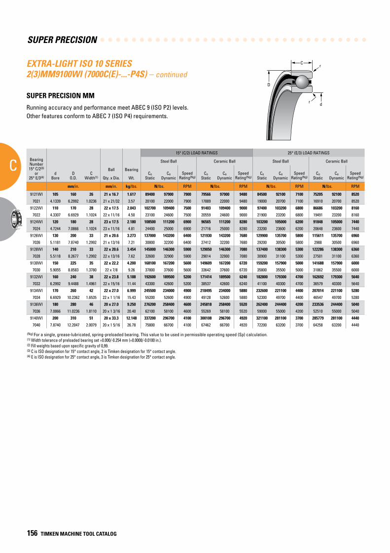
SUPER PRECISION
C
156 TIMKEN MACHINE TOOL CATALOG
C
D
r
dr
BearingNumber15° C/2(3)
or25° E/3(4)
dBore
DO.D.
CWidth(1)
Ball Bearing
15° (C/2) LOAD RATINGS 25° (E/3) LOAD RATINGS
rRad.(2)
Suggested Shoulder Diameters Shaft Diameter Mounting Fits
FIXED FLOATING
Steel Ball Ceramic Ball Steel Ball Ceramic Ball Housing Bore (Stationary) Mounting Fits Housing Bore
(Stationary) Mounting Fits
CoStatic
CeDynamic
SpeedRating(Ng)
CoStatic
CeDynamic
SpeedRating(Ng)
CoStatic
CeDynamic
SpeedRating(Ng)
CoStatic
CeDynamic
SpeedRating(Ng)
Shaft Housing
Qty. x Dia. Wt. Max. Min. Max. Min. Max. Min. Loose Tight Max. Min. Tight Loose Max. Min. Loose Loose
mm/in. mm/in. kg/lbs. N/lbs. RPM N/lbs. RPM N/lbs. RPM N/lbs. RPM mm/in. mm/in. mm/in. mm/in. mm/in. mm/in. mm/in. mm/in. mm/in.
9121WI 105 160 26 21 x 16.7 1.617 89400 97900 7900 79566 97900 9480 84500 92100 7100 75205 92100 8520 2.0 116.5 115.7 150.0 149.2 105.005 104.995 0.005 0.013 160.009 160.000 0.000 0.022 160.022 160.012 0.033 0.012
7021 4.1339 6.2992 1.0236 21 x 21/32 3.57 20100 22000 7900 17889 22000 9480 19000 20700 7100 16910 20700 8520 0.079 4.59 4.56 5.91 5.88 4.13410 4.13370 0.00020 0.00050 6.29960 6.29920 0.00000 0.00080 6.30010 6.29970 0.00130 0.00050
9122WI 110 170 28 22 x 17.5 2.043 102700 109400 7500 91403 109400 9000 97400 103200 6800 86686 103200 8160 2.0 123.1 122.3 158.4 157.6 110.005 109.995 0.005 0.013 170.010 170.000 0.000 0.020 170.022 170.012 0.032 0.012
7022 4.3307 6.6929 1.1024 22 x 11/16 4.50 23100 24600 7500 20559 24600 9000 21900 23200 6800 19491 23200 8160 0.079 4.85 4.82 6.24 6.21 4.33090 4.33050 0.00020 0.00050 6.69330 6.69290 0.00000 0.00080 6.69380 6.69340 0.00130 0.00050
9124WI 120 180 28 23 x 17.5 2.180 108500 111200 6900 96565 111200 8280 103200 105000 6200 91848 105000 7440 2.0 133.2 132.5 168.3 167.5 120.005 119.995 0.005 0.013 180.010 180.000 0.000 0.020 180.022 180.012 0.032 0.012
7024 4.7244 7.0866 1.1024 23 x 11/16 4.81 24400 25000 6900 21716 25000 8280 23200 23600 6200 20648 23600 7440 0.079 5.25 5.22 6.63 6.60 4.72460 4.72420 0.00020 0.00050 7.08700 7.08660 0.00000 0.00080 7.08750 7.08710 0.00130 0.00050
9126WI 130 200 33 21 x 20.6 3.273 137000 143200 6400 121930 143200 7680 129900 135700 5800 115611 135700 6960 2.0 144.9 144.2 186.6 185.8 130.005 129.995 0.005 0.015 200.011 200.000 0.000 0.022 200.025 200.015 0.036 0.015
7026 5.1181 7.8740 1.2992 21 x 13/16 7.21 30800 32200 6400 27412 32200 7680 29200 30500 5800 2988 30500 6960 0.079 5.71 5.68 7.35 7.32 5.11830 5.11790 0.00020 0.00060 7.87450 7.87400 0.00000 0.00090 7.87500 7.87460 0.00150 0.00060
9128WI 140 210 33 22 x 20.6 3.454 145000 146300 5900 129050 146300 7080 137400 138300 5300 122286 138300 6360 2.0 155.1 154.3 196.5 195.7 140.005 139.995 0.005 0.015 210.011 210.000 0.000 0.022 210.025 210.015 0.036 0.015
7028 5.5118 8.2677 1.2992 22 x 13/16 7.62 32600 32900 5900 29014 32900 7080 30900 31100 5300 27501 31100 6360 0.079 6.11 6.08 7.74 7.71 5.51200 5.51160 0.00020 0.00060 8.26820 8.26770 0.00000 0.00090 8.26870 8.26830 0.00150 0.00060
9130WI 150 225 35 22 x 22.2 4.200 168100 167200 5600 149609 167200 6720 159200 157900 5000 141688 157900 6000 2.0 166.0 165.2 210.7 209.9 150.005 149.995 0.005 0.015 225.011 225.000 0.000 0.022 225.025 225.015 0.036 0.015
7030 5.9055 8.8583 1.3780 22 x 7/8 9.26 37800 37600 5600 33642 37600 6720 35800 35500 5000 31862 35500 6000 0.079 6.54 6.51 8.30 8.27 5.90570 5.90530 0.00020 0.00060 8.85880 8.85830 0.00000 0.00090 8.85930 8.85890 0.00150 0.00060
9132WI 160 240 38 22 x 23.8 5.188 192600 189500 5200 171414 189500 6240 182800 179300 4700 162692 179300 5640 2.0 176.9 176.2 224.7 223.9 160.005 159.995 0.005 0.015 240.011 240.000 0.000 0.022 240.025 240.015 0.041 0.018
7032 6.2992 9.4488 1.4961 22 x 15/16 11.44 43300 42600 5200 38537 42600 6240 41100 40300 4700 36579 40300 5640 0.079 6.97 6.94 8.85 8.82 6.29940 6.29900 0.00020 0.00060 9.44930 9.44880 0.00000 0.00090 9.45000 9.44940 0.00160 0.00060
9134WI 170 260 42 22 x 27.0 6.999 245500 234000 4900 218495 234000 5880 232600 221100 4400 207014 221100 5280 2.0 188.6 187.8 242.7 241.9 170.005 169.995 0.005 0.015 260.011 260.000 0.000 0.024 260.030 260.015 0.044 0.018
7034 6.6929 10.2362 1.6535 22 x 1 1/16 15.43 55200 52600 4900 49128 52600 5880 52300 49700 4400 46547 49700 5280 0.079 7.43 7.40 9.56 9.53 6.69310 6.69270 0.00020 0.00060 10.23670 10.23620 0.00000 0.00100 10.23750 10.23700 0.00180 0.00080
9136WI 180 280 46 20 x 27.0 9.250 276200 258400 4600 245818 258400 5520 262400 244400 4200 233536 244400 5040 2.0 200.5 199.8 261.0 260.2 180.008 179.993 0.007 0.018 280.013 280.000 0.000 0.026 280.031 280.018 0.044 0.018
7036 7.0866 11.0236 1.8110 20 x 1 3/16 20.40 62100 58100 4600 55269 58100 5520 59000 55000 4200 52510 55000 5040 0.079 7.90 7.87 10.28 10.25 7.08690 7.08630 0.00030 0.00070 11.02410 11.02360 0.00000 0.00100 11.02490 11.02440 0.00180 0.00080
9140WI 200 310 51 20 x 33.3 12.148 337200 296700 4100 300108 296700 4920 321100 281100 3700 285779 281100 4440 2.0 222.4 221.6 289.2 288.4 200.008 199.993 0.007 0.019 310.013 310.000 0.000 0.026 310.031 310.018 0.044 0.018
7040 7.8740 12.2047 2.0079 20 x 1 5/16 26.78 75800 66700 4100 67462 66700 4920 72200 63200 3700 64258 63200 4440 0.079 8.76 8.73 11.39 11.36 7.87430 7.87370 0.00030 0.00080 12.20520 12.20470 0.00000 0.00100 12.20600 12.20550 0.00180 0.00080
EXTRA-LIGHT ISO 10 SERIES 2(3)MM9100WI (7000C(E)-...-P4S) – continued SUPER PRECISION MM
Running accuracy and performance meet ABEC 9 (ISO P2) levels. Other features conform to ABEC 7 (ISO P4) requirements.
(Ng) For a single, grease-lubricated, spring-preloaded bearing. This value to be used in permissible operating speed (Sp) calculation.(1) Width tolerance of preloaded bearing set +0.000/-0.254 mm (+0.0000/-0.0100 in.).(2) Fill weights based upon specific gravity of 0,99.(3) C is ISO designation for 15° contact angle, 2 is Timken designation for 15° contact angle.(4) E is ISO designation for 25° contact angle, 3 is Timken designation for 25° contact angle.

Ball Bearings
C
TIMKEN MACHINE TOOL CATALOG 157
BearingNumber15° C/2(3)
or25° E/3(4)
dBore
DO.D.
CWidth(1)
Ball Bearing
15° (C/2) LOAD RATINGS 25° (E/3) LOAD RATINGS
rRad.(2)
Suggested Shoulder Diameters Shaft Diameter Mounting Fits
FIXED FLOATING
Steel Ball Ceramic Ball Steel Ball Ceramic Ball Housing Bore (Stationary) Mounting Fits Housing Bore
(Stationary) Mounting Fits
CoStatic
CeDynamic
SpeedRating(Ng)
CoStatic
CeDynamic
SpeedRating(Ng)
CoStatic
CeDynamic
SpeedRating(Ng)
CoStatic
CeDynamic
SpeedRating(Ng)
Shaft Housing
Qty. x Dia. Wt. Max. Min. Max. Min. Max. Min. Loose Tight Max. Min. Tight Loose Max. Min. Loose Loose
mm/in. mm/in. kg/lbs. N/lbs. RPM N/lbs. RPM N/lbs. RPM N/lbs. RPM mm/in. mm/in. mm/in. mm/in. mm/in. mm/in. mm/in. mm/in. mm/in.
9121WI 105 160 26 21 x 16.7 1.617 89400 97900 7900 79566 97900 9480 84500 92100 7100 75205 92100 8520 2.0 116.5 115.7 150.0 149.2 105.005 104.995 0.005 0.013 160.009 160.000 0.000 0.022 160.022 160.012 0.033 0.012
7021 4.1339 6.2992 1.0236 21 x 21/32 3.57 20100 22000 7900 17889 22000 9480 19000 20700 7100 16910 20700 8520 0.079 4.59 4.56 5.91 5.88 4.13410 4.13370 0.00020 0.00050 6.29960 6.29920 0.00000 0.00080 6.30010 6.29970 0.00130 0.00050
9122WI 110 170 28 22 x 17.5 2.043 102700 109400 7500 91403 109400 9000 97400 103200 6800 86686 103200 8160 2.0 123.1 122.3 158.4 157.6 110.005 109.995 0.005 0.013 170.010 170.000 0.000 0.020 170.022 170.012 0.032 0.012
7022 4.3307 6.6929 1.1024 22 x 11/16 4.50 23100 24600 7500 20559 24600 9000 21900 23200 6800 19491 23200 8160 0.079 4.85 4.82 6.24 6.21 4.33090 4.33050 0.00020 0.00050 6.69330 6.69290 0.00000 0.00080 6.69380 6.69340 0.00130 0.00050
9124WI 120 180 28 23 x 17.5 2.180 108500 111200 6900 96565 111200 8280 103200 105000 6200 91848 105000 7440 2.0 133.2 132.5 168.3 167.5 120.005 119.995 0.005 0.013 180.010 180.000 0.000 0.020 180.022 180.012 0.032 0.012
7024 4.7244 7.0866 1.1024 23 x 11/16 4.81 24400 25000 6900 21716 25000 8280 23200 23600 6200 20648 23600 7440 0.079 5.25 5.22 6.63 6.60 4.72460 4.72420 0.00020 0.00050 7.08700 7.08660 0.00000 0.00080 7.08750 7.08710 0.00130 0.00050
9126WI 130 200 33 21 x 20.6 3.273 137000 143200 6400 121930 143200 7680 129900 135700 5800 115611 135700 6960 2.0 144.9 144.2 186.6 185.8 130.005 129.995 0.005 0.015 200.011 200.000 0.000 0.022 200.025 200.015 0.036 0.015
7026 5.1181 7.8740 1.2992 21 x 13/16 7.21 30800 32200 6400 27412 32200 7680 29200 30500 5800 2988 30500 6960 0.079 5.71 5.68 7.35 7.32 5.11830 5.11790 0.00020 0.00060 7.87450 7.87400 0.00000 0.00090 7.87500 7.87460 0.00150 0.00060
9128WI 140 210 33 22 x 20.6 3.454 145000 146300 5900 129050 146300 7080 137400 138300 5300 122286 138300 6360 2.0 155.1 154.3 196.5 195.7 140.005 139.995 0.005 0.015 210.011 210.000 0.000 0.022 210.025 210.015 0.036 0.015
7028 5.5118 8.2677 1.2992 22 x 13/16 7.62 32600 32900 5900 29014 32900 7080 30900 31100 5300 27501 31100 6360 0.079 6.11 6.08 7.74 7.71 5.51200 5.51160 0.00020 0.00060 8.26820 8.26770 0.00000 0.00090 8.26870 8.26830 0.00150 0.00060
9130WI 150 225 35 22 x 22.2 4.200 168100 167200 5600 149609 167200 6720 159200 157900 5000 141688 157900 6000 2.0 166.0 165.2 210.7 209.9 150.005 149.995 0.005 0.015 225.011 225.000 0.000 0.022 225.025 225.015 0.036 0.015
7030 5.9055 8.8583 1.3780 22 x 7/8 9.26 37800 37600 5600 33642 37600 6720 35800 35500 5000 31862 35500 6000 0.079 6.54 6.51 8.30 8.27 5.90570 5.90530 0.00020 0.00060 8.85880 8.85830 0.00000 0.00090 8.85930 8.85890 0.00150 0.00060
9132WI 160 240 38 22 x 23.8 5.188 192600 189500 5200 171414 189500 6240 182800 179300 4700 162692 179300 5640 2.0 176.9 176.2 224.7 223.9 160.005 159.995 0.005 0.015 240.011 240.000 0.000 0.022 240.025 240.015 0.041 0.018
7032 6.2992 9.4488 1.4961 22 x 15/16 11.44 43300 42600 5200 38537 42600 6240 41100 40300 4700 36579 40300 5640 0.079 6.97 6.94 8.85 8.82 6.29940 6.29900 0.00020 0.00060 9.44930 9.44880 0.00000 0.00090 9.45000 9.44940 0.00160 0.00060
9134WI 170 260 42 22 x 27.0 6.999 245500 234000 4900 218495 234000 5880 232600 221100 4400 207014 221100 5280 2.0 188.6 187.8 242.7 241.9 170.005 169.995 0.005 0.015 260.011 260.000 0.000 0.024 260.030 260.015 0.044 0.018
7034 6.6929 10.2362 1.6535 22 x 1 1/16 15.43 55200 52600 4900 49128 52600 5880 52300 49700 4400 46547 49700 5280 0.079 7.43 7.40 9.56 9.53 6.69310 6.69270 0.00020 0.00060 10.23670 10.23620 0.00000 0.00100 10.23750 10.23700 0.00180 0.00080
9136WI 180 280 46 20 x 27.0 9.250 276200 258400 4600 245818 258400 5520 262400 244400 4200 233536 244400 5040 2.0 200.5 199.8 261.0 260.2 180.008 179.993 0.007 0.018 280.013 280.000 0.000 0.026 280.031 280.018 0.044 0.018
7036 7.0866 11.0236 1.8110 20 x 1 3/16 20.40 62100 58100 4600 55269 58100 5520 59000 55000 4200 52510 55000 5040 0.079 7.90 7.87 10.28 10.25 7.08690 7.08630 0.00030 0.00070 11.02410 11.02360 0.00000 0.00100 11.02490 11.02440 0.00180 0.00080
9140WI 200 310 51 20 x 33.3 12.148 337200 296700 4100 300108 296700 4920 321100 281100 3700 285779 281100 4440 2.0 222.4 221.6 289.2 288.4 200.008 199.993 0.007 0.019 310.013 310.000 0.000 0.026 310.031 310.018 0.044 0.018
7040 7.8740 12.2047 2.0079 20 x 1 5/16 26.78 75800 66700 4100 67462 66700 4920 72200 63200 3700 64258 63200 4440 0.079 8.76 8.73 11.39 11.36 7.87430 7.87370 0.00030 0.00080 12.20520 12.20470 0.00000 0.00100 12.20600 12.20550 0.00180 0.00080
WI CONSTRUCTION
• Incorporates low shoulder on non-thrust side of outer rings.
• Balls separated by one-piece cage piloted against a ground thrust shoulder land of the outer ring.
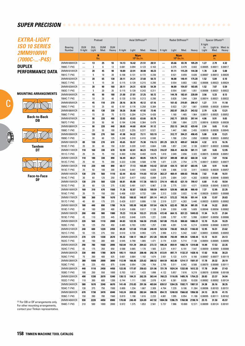
SUPER PRECISION
C
158 TIMKEN MACHINE TOOL CATALOG
EXTRA-LIGHT ISO 10 SERIES 2MM9100WI (7000C-...-P4S)DUPLEX PERFORMANCE DATA
Preload Axial Stiffness(1) Radial Stiffness(1) Spacer Offsets(1)
Bearing Number
DUXX-light
DULLight
DUMMed.
DUHHeavy X-light Light Med. Heavy X-light Light Med. Heavy
X-light to
LightLight toMed.
Med. toHeavy
N lbs.
N/µm 106 lbs./in.
N/µm 106 lbs./in.
µm in.
2MM9100WICR — 13 25 55 14.13 16.42 21.51 28.51 — 65.66 83.78 105.29 1.27 2.79 4.327000C-T-P4S — 3 6 12 0.081 0.094 0.123 0.163 — 0.375 0.479 0.602 0.00005 0.00011 0.000172MM9101WICR — 20 45 90 18.89 22.91 30.08 40.23 — 91.11 115.29 144.38 1.78 3.30 5.087001C-T-P4S — 5 10 20 0.108 0.131 0.172 0.230 — 0.521 0.659 0.826 0.00007 0.00013 0.000202MM9102WICR — 20 65 130 20.11 24.31 37.60 50.72 — 96.88 140.41 175.20 1.52 5.84 6.107002C-T-P4S — 5 15 30 0.115 0.139 0.215 0.290 — 0.554 0.803 1.002 0.00006 0.00023 0.000242MM9103WICR — 20 90 160 20.11 24.31 42.50 54.39 — 96.89 154.07 183.85 1.52 7.87 5.597003C-T-P4S — 5 20 35 0.115 0.139 0.243 0.311 — 0.554 0.881 1.051 0.00006 0.00031 0.000222MM9104WICR — 45 90 180 21.00 27.81 37.25 50.72 — 144.78 182.61 228.09 3.56 5.33 8.137004C-T-P4S — 10 20 40 0.120 0.159 0.213 0.290 — 0.828 1.044 1.304 0.00014 0.00021 0.00032
2MM9105WICR — 45 110 270 28.16 30.78 45.12 67.16 — 161.42 219.81 290.47 1.27 7.11 11.187005C-T-P4S — 10 25 60 0.161 0.176 0.258 0.384 — 0.923 1.257 1.661 0.00005 0.00028 0.000442MM9106WICR — 65 130 330 30.26 35.68 47.92 73.46 — 202.87 256.21 343.52 2.79 6.35 13.217006C-T-P4S — 15 30 75 0.173 0.204 0.274 0.420 — 1.160 1.465 1.964 0.00011 0.00025 0.000522MM9107WICR — 90 220 400 33.93 43.03 63.66 83.78 — 242.71 329.53 397.44 4.06 9.91 9.657007C-T-P4S — 20 50 90 0.194 0.246 0.364 0.479 — 1.388 1.884 2.272 0.00016 0.00039 0.000382MM9108WICR — 90 220 440 38.65 44.60 65.94 91.12 — 253.13 344.22 429.40 2.54 9.65 11.437008C-T-P4S — 20 50 100 0.221 0.255 0.377 0.521 — 1.447 1.968 2.455 0.00010 0.00038 0.000452MM9109WICR — 130 270 560 41.98 54.22 73.11 103.19 — 312.77 394.21 498.45 5.08 8.38 13.217009C-T-P4S — 30 60 125 0.240 0.310 0.418 0.590 — 1.788 2.254 2.850 0.00020 0.00033 0.000522MM9110WICR 89 130 270 670 45.65 55.97 75.38 116.13 281.29 324.72 409.67 548.84 4.32 8.13 16.767010C-T-P4S 20 30 60 150 0.261 0.320 0.431 0.664 1.606 1.857 2.342 3.138 0.00017 0.00032 0.000662MM9111WICR 110 160 330 670 52.99 62.61 86.23 118.23 316.97 358.41 464.50 581.11 3.81 9.65 12.957011C-T-P4S 25 35 75 150 0.303 0.358 0.493 0.676 1.810 2.049 2.656 3.323 0.00015 0.00038 0.000512MM9112WICR 110 180 330 890 56.49 68.21 88.85 139.75 327.57 389.08 481.62 660.30 4.32 7.87 19.567012C-T-P4S 25 40 75 200 0.323 0.390 0.508 0.799 1.871 2.225 2.754 3.775 0.00017 0.00031 0.000772MM9113WICR 110 220 440 890 60.17 77.13 103.89 143.42 337.69 434.73 547.87 683.95 5.84 9.91 14.487013C-T-P4S 25 50 100 200 0.344 0.441 0.594 0.820 1.928 2.486 3.133 3.911 0.00023 0.00039 0.000572MM9114WICR 130 270 560 1110 62.44 83.43 114.03 157.24 363.37 469.41 600.03 749.06 7.62 11.68 16.517014C-T-P4S 30 60 125 250 0.357 0.477 0.652 0.899 2.075 2.684 3.431 4.283 0.00030 0.00046 0.000652MM9115WICR 130 270 560 1220 66.81 85.88 117.36 169.13 374.14 485.42 621.10 799.47 6.60 11.43 18.547015C-T-P4S 30 60 125 275 0.382 0.491 0.671 0.967 2.136 2.775 3.551 4.571 0.00026 0.00045 0.000732MM9116WICR 160 310 670 1560 71.36 92.87 128.03 189.59 404.91 529.96 685.98 900.40 7.37 12.95 22.357016C-T-P4S 35 70 150 350 0.408 0.531 0.732 1.084 2.312 3.030 3.922 5.148 0.00029 0.00051 0.000882MM9117WICR 180 360 780 1670 75.03 100.92 140.97 201.14 441.21 573.22 745.56 951.44 8.38 13.97 20.837017C-T-P4S 40 80 175 375 0.429 0.577 0.806 1.150 2.519 3.277 4.263 5.440 0.00033 0.00055 0.000822MM9118WICR 180 440 890 1780 74.16 105.99 142.89 197.64 436.76 622.45 785.34 981.05 11.68 14.22 20.837018C-T-P4S 40 100 200 400 0.424 0.606 0.817 1.130 2.494 3.559 4.490 5.609 0.00046 0.00056 0.000822MM9119WICR 200 490 980 1980 79.23 113.34 153.21 213.55 472.40 664.15 837.23 1049.03 11.94 14.73 21.847019C-T-P4S 45 110 220 445 0.453 0.648 0.876 1.221 2.698 3.797 4.787 5.998 0.00047 0.00058 0.000862MM9120WICR 220 560 1110 2000 84.83 122.95 166.50 219.85 507.88 715.43 900.60 1086.81 12.70 15.24 18.297020C-T-P4S 50 125 250 450 0.485 0.703 0.952 1.257 2.900 4.091 5.149 6.214 0.00050 0.00060 0.000722MM9121WICR 240 600 1220 2450 89.20 127.68 173.68 240.49 523.56 736.82 934.23 1166.02 12.95 16.51 23.627021C-T-P4S 55 135 275 550 0.510 0.730 0.993 1.375 2.990 4.213 5.342 6.667 0.00051 0.00065 0.000932MM9122WICR 270 670 1330 2670 95.32 138.17 186.27 257.28 555.90 792.09 999.34 1248.44 13.72 16.51 24.137022C-T-P4S 60 150 300 600 0.545 0.790 1.065 1.471 3.174 4.529 5.714 7.138 0.00054 0.00065 0.000952MM9124WICR 290 780 1560 2890 102.84 151.29 204.63 273.72 590.28 859.91 1082.79 1319.88 14.99 17.53 22.357024C-T-P4S 65 175 350 650 0.588 0.865 1.170 1.565 3.371 4.917 6.191 7.547 0.00059 0.00069 0.000882MM9126WICR 330 890 1780 3670 105.11 154.61 208.48 292.78 613.01 897.71 1132.37 1428.16 17.02 19.56 30.237026C-T-P4S 75 200 400 825 0.601 0.884 1.192 1.674 3.501 5.133 6.474 8.166 0.00067 0.00077 0.001192MM9128WICR 380 1000 2000 3890 112.99 166.85 225.62 308.52 664.59 963.80 1214.17 1501.97 17.78 20.32 28.197028C-T-P4S 85 225 450 875 0.646 0.954 1.290 1.764 3.795 5.511 6.942 8.588 0.00070 0.00080 0.001112MM9130WICR 440 1110 2450 4450 122.95 177.87 250.63 331.96 721.78 1024.34 1332.00 1612.33 17.78 24.89 27.437030C-T-P4S 100 250 550 1000 0.703 1.017 1.433 1.898 4.122 5.857 7.616 9.219 0.00070 0.00098 0.001082MM9132WICR 490 1330 2670 5340 130.13 194.31 262.35 363.44 760.23 1116.05 1405.76 1754.23 20.83 23.37 34.047032C-T-P4S 110 300 600 1200 0.744 1.111 1.500 2.078 4.341 6.381 8.038 10.030 0.00082 0.00092 0.001342MM9134WICR 580 1670 3340 6670 141.49 215.83 291.56 403.84 839.57 1264.35 1592.71 1987.51 24.38 26.16 38.357034C-T-P4S 130 375 750 1500 0.809 1.234 1.667 2.309 4.794 7.229 9.106 11.364 0.00096 0.00103 0.001512MM9136WICR 670 1730 3470 6940 143.24 209.53 282.64 390.55 854.72 1240.93 1566.02 1956.50 24.13 28.19 41.157036C-T-P4S 150 390 780 1560 0.819 1.198 1.616 2.233 4.881 7.095 8.954 11.186 0.00095 0.00111 0.001622MM9140WICR 930 2220 4450 8900 170.00 240.49 324.09 447.92 1004.58 1396.79 1760.98 2198.74 25.15 31.50 45.977040C-T-P4S 210 500 1000 2000 0.972 1.375 1.853 2.561 5.737 7.986 10.069 12.571 0.00099 0.00124 0.00181
(1) For DB or DF arrangements only. For other mounting arrangements, contact your Timken representative.
MOUNTING ARRANGEMENTS
Back-to-BackDB
TandemDT
Face-to-FaceDF
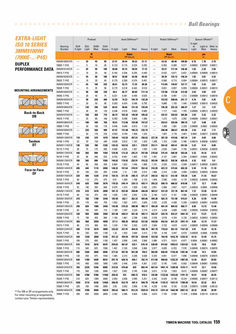
Ball Bearings
C
TIMKEN MACHINE TOOL CATALOG 159
EXTRA-LIGHT ISO 10 SERIES 3MM9100WI (7000E-...-P4S)DUPLEX PERFORMANCE DATA
Preload Axial Stiffness(1) Radial Stiffness(1) Spacer Offsets(1)
Bearing Number
DUXX-light
DULLight
DUMMed.
DUHHeavy X-light Light Med. Heavy X-light Light Med. Heavy
X-light to
LightLight toMed.
Med. toHeavy
N lbs.
N/µm 106 lbs./in.
N/µm 106 lbs./in.
µm in.
3MM9100WICR — 20 45 90 21.51 30.44 39.23 51.11 — 63.42 80.40 100.86 0.76 1.78 2.797000E-T-P4S — 5 10 20 0.123 0.174 0.224 0.292 — 0.363 0.460 0.577 0.00003 0.00007 0.000113MM9101WICR — 45 90 180 28.68 45.15 58.59 77.10 — 93.27 117.34 146.46 1.02 2.29 3.567001E-T-P4S — 10 20 40 0.164 0.258 0.335 0.440 — 0.533 0.671 0.837 0.00004 0.00009 0.000143MM9102WICR — 45 90 180 30.61 50.68 65.58 85.94 — 99.34 125.12 156.34 1.02 3.81 4.327002E-T-P4S — 10 20 40 0.175 0.289 0.374 0.491 — 0.568 0.715 0.894 0.00004 0.00015 0.000173MM9103WICR — 65 160 220 30.61 55.73 77.33 89.38 — 113.84 149.87 167.71 1.02 5.33 3.817003E-T-P4S — 15 35 50 0.175 0.318 0.442 0.510 — 0.651 0.857 0.959 0.00004 0.00021 0.000153MM9104WICR — 90 180 330 40.4 66.77 86.69 111.16 — 137.86 173.36 212.00 2.03 3.05 4.577004E-T-P4S — 20 40 75 0.231 0.381 0.495 0.635 — 0.788 0.991 1.212 0.00008 0.00012 0.000183MM9105WICR — 90 220 400 52.99 74.23 104.70 132.20 — 153.93 208.66 251.77 0.76 3.81 6.357005E-T-P4S — 20 50 90 0.303 0.424 0.598 0.755 — 0.880 1.193 1.440 0.00003 0.00015 0.000253MM9106WICR — 130 290 530 60.52 90.66 121.43 155.04 — 195.36 252.33 306.97 1.27 3.3 7.377006E-T-P4S — 30 65 120 0.346 0.518 0.693 0.885 — 1.117 1.443 1.755 0.00005 0.00013 0.000293MM9107WICR — 160 360 710 68.74 103.35 140.95 185.62 — 222.51 293.03 365.86 2.03 5.33 5.337007E-T-P4S — 35 80 160 0.393 0.590 0.805 1.060 — 1.272 1.675 2.092 0.00008 0.00021 0.000213MM9108WICR — 180 440 760 78.01 113.06 159.90 197.67 — 243.01 329.06 389.76 1.27 5.08 6.357008E-T-P4S — 40 100 170 0.446 0.646 0.913 1.129 — 1.389 1.881 2.229 0.00005 0.0002 0.000253MM9109WICR — 220 560 980 87.97 131.08 185.23 232.10 — 280.98 380.67 455.96 2.54 4.32 7.117009E-T-P4S — 50 125 220 0.503 0.749 1.058 1.325 — 1.607 2.176 2.607 0.0001 0.00017 0.000283MM9110WICR 110 240 670 1070 109.84 142.02 207.61 250.63 227.34 301.39 419.66 487.34 3.81 9.65 6.867010E-T-P4S 25 55 150 240 0.628 0.812 1.187 1.433 1.298 1.723 2.399 2.786 0.00015 0.00038 0.000273MM9111WICR 130 330 780 1330 120.33 163.53 225.1 278.97 253.11 354.42 469.41 557.84 5.33 9.14 8.897011E-T-P4S 30 75 175 300 0.688 0.935 1.287 1.595 1.445 2.026 2.684 3.190 0.00021 0.00036 0.000353MM9112WICR 160 360 890 1450 129.95 173.33 245.21 297.68 278.69 375.44 508.40 593.68 5.33 10.16 8.137012E-T-P4S 35 80 200 325 0.743 0.991 1.402 1.702 1.591 2.147 2.907 3.394 0.00021 0.0004 0.000323MM9113WICR 180 360 890 1560 140.62 178.92 252.91 316.22 303.09 388.33 526.36 629.45 4.32 9.91 9.47013E-T-P4S 40 80 200 350 0.804 1.023 1.446 1.808 1.731 2.220 3.010 3.599 0.00017 0.00039 0.000373MM9114WICR 200 440 1110 2000 148.32 197.64 278.97 352.42 316.28 423.12 573.64 692.20 5.59 11.18 11.187014E-T-P4S 45 100 250 450 0.848 1.13 1.595 2.015 1.806 2.419 3.280 3.958 0.00022 0.00044 0.000443MM9115WICR 220 490 1220 2110 159.16 211.45 298.73 371.31 340.43 452.13 612.48 729.26 5.84 11.43 10.677015E-T-P4S 50 110 275 475 0.91 1.209 1.708 2.123 1.944 2.585 3.502 4.170 0.00023 0.00045 0.000423MM9116WICR 240 620 1560 2670 170.53 240.14 339.13 420.11 359.22 508.19 688.62 818.08 7.37 12.7 11.687016E-T-P4S 55 140 350 600 0.975 1.373 1.939 2.402 2.051 2.906 3.937 4.677 0.00029 0.0005 0.000463MM9117WICR 270 670 1670 2890 181.72 253.95 358.89 446.69 383.57 537.29 727.78 867.49 7.37 12.95 12.197017E-T-P4S 60 150 375 650 1.039 1.452 2.052 2.554 2.190 3.072 4.161 4.960 0.00029 0.00051 0.000483MM9118WICR 270 760 1780 3340 183.99 262.7 362.22 465.06 394.38 565.75 751.98 919.61 8.38 12.95 14.997018E-T-P4S 65 170 400 750 1.052 1.502 2.071 2.659 2.252 3.235 4.300 5.258 0.00033 0.00051 0.000593MM9119WICR 290 820 1980 3450 193.96 279.32 388.98 485.17 405.28 601.34 804.52 960.71 8.89 13.72 13.467019E-T-P4S 65 185 445 775 1.109 1.597 2.224 2.774 2.314 3.438 4.600 5.493 0.00035 0.00054 0.000533MM9120WICR 330 850 2000 3560 207.08 290.51 401.92 505.11 442.97 625.70 833.21 1001.76 8.13 13.21 13.727020E-T-P4S 75 190 450 800 1.184 1.661 2.298 2.888 2.530 3.578 4.764 5.728 0.00032 0.00052 0.000543MM9121WICR 360 960 2050 4090 217.4 308.35 409.62 537.82 448.80 652.64 841.25 1051.10 8.89 12.19 17.277021E-T-P4S 80 215 460 920 1.243 1.763 2.342 3.075 2.563 3.732 4.810 6.010 0.00035 0.00048 0.000683MM9122WICR 400 1110 2670 4890 232.62 337.91 469.43 596.76 487.78 718.63 961.43 1167.28 9.91 15.24 16.767022E-T-P4S 90 250 600 1100 1.33 1.932 2.684 3.412 2.785 4.109 5.497 6.674 0.00039 0.0006 0.000663MM9124WICR 440 1220 2890 5120 251.33 359.94 497.59 624.04 523.58 764.45 1016.78 1220.33 10.16 15.49 15.757024E-T-P4S 100 275 650 1150 1.437 2.058 2.845 3.568 2.990 4.371 5.814 6.977 0.0004 0.00061 0.000623MM9126WICR 510 1510 3670 6670 259.03 381.81 533.1 676.16 538.89 814.82 1093.67 1324.03 12.45 18.8 19.817026E-T-P4S 115 340 825 1500 1.481 2.183 3.048 3.866 3.077 4.659 6.253 7.570 0.00049 0.00074 0.000783MM9128WICR 580 1560 3890 6890 277.22 397.55 561.08 704.5 583.89 848.49 1150.30 1381.06 11.68 19.3 19.057028E-T-P4S 130 350 875 1550 1.585 2.273 3.208 4.028 3.334 4.851 6.577 7.896 0.00046 0.00076 0.000753MM9130WICR 640 1780 4450 8010 297.16 428.16 604.1 762.74 617.68 908.66 1232.22 1487.09 12.45 20.57 20.837030E-T-P4S 145 400 1000 1800 1.699 2.448 3.454 4.361 3.527 5.195 7.045 8.503 0.00049 0.00081 0.000823MM9132WICR 760 2220 5340 8900 319.54 470.66 655 802.44 667.54 1001.74 1338.58 1576.11 14.73 22.1 19.567032E-T-P4S 170 500 1200 2000 1.827 2.691 3.745 4.588 3.812 5.728 7.653 9.012 0.00058 0.00087 0.000773MM9134WICR 930 2780 5780 11560 359.42 531 698.73 918.4 742.80 1123.56 1433.83 1791.10 16.51 19.56 28.457034E-T-P4S 210 625 1300 2600 2.055 3.036 3.995 5.251 4.242 6.424 8.198 10.241 0.00065 0.00077 0.001123MM9136WICR 1020 3110 6230 12460 358.55 533.79 691.9 908.78 742.40 1135.57 1431.01 1788.58 18.54 20.32 30.97036E-T-P4S 230 700 1400 2800 2.05 3.052 3.956 5.196 4.239 6.493 8.182 10.226 0.00073 0.0008 0.001223MM9140WICR 1250 3780 8900 16010 395.62 588.71 812.24 1025.61 818.74 1251.44 1662.98 2007.43 20.32 28.96 30.997040E-T-P4S 280 850 2000 3600 2.262 3.366 4.644 5.864 4.675 7.155 9.508 11.478 0.0008 0.00114 0.00122
(1) For DB or DF arrangements only. For other mounting arrangements, contact your Timken representative.
MOUNTING ARRANGEMENTS
Back-to-BackDB
TandemDT
Face-to-FaceDF
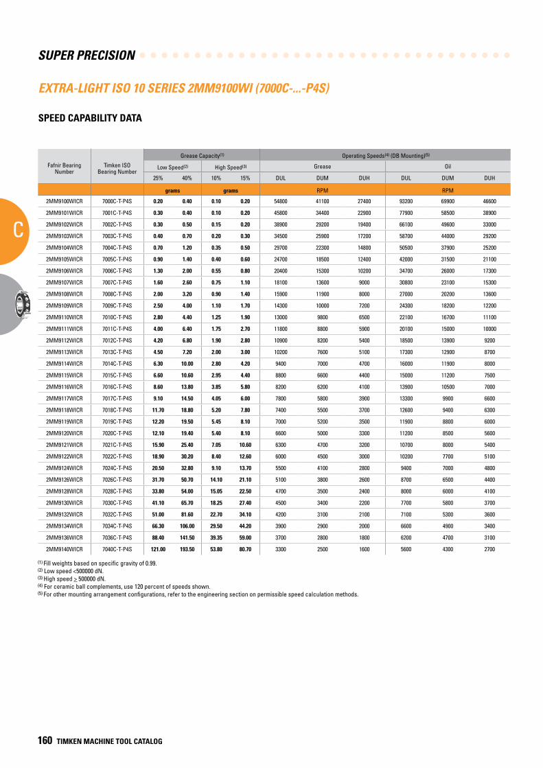
SUPER PRECISION
C
160 TIMKEN MACHINE TOOL CATALOG
EXTRA-LIGHT ISO 10 SERIES 2MM9100WI (7000C-...-P4S)
SPEED CAPABILITY DATA
Fafnir Bearing Number
Timken ISO Bearing Number
Grease Capacity(1) Operating Speeds(4) (DB Mounting)(5)
Low Speed(2) High Speed(3) Grease Oil
25% 40% 10% 15% DUL DUM DUH DUL DUM DUH
grams grams RPM RPM
2MM9100WICR 7000C-T-P4S 0.20 0.40 0.10 0.20 54800 41100 27400 93200 69900 46600
2MM9101WICR 7001C-T-P4S 0.30 0.40 0.10 0.20 45800 34400 22900 77900 58500 38900
2MM9102WICR 7002C-T-P4S 0.30 0.50 0.15 0.20 38900 29200 19400 66100 49600 33000
2MM9103WICR 7003C-T-P4S 0.40 0.70 0.20 0.30 34500 25900 17200 58700 44000 29200
2MM9104WICR 7004C-T-P4S 0.70 1.20 0.35 0.50 29700 22300 14800 50500 37900 25200
2MM9105WICR 7005C-T-P4S 0.90 1.40 0.40 0.60 24700 18500 12400 42000 31500 21100
2MM9106WICR 7006C-T-P4S 1.30 2.00 0.55 0.80 20400 15300 10200 34700 26000 17300
2MM9107WICR 7007C-T-P4S 1.60 2.60 0.75 1.10 18100 13600 9000 30800 23100 15300
2MM9108WICR 7008C-T-P4S 2.00 3.20 0.90 1.40 15900 11900 8000 27000 20200 13600
2MM9109WICR 7009C-T-P4S 2.50 4.00 1.10 1.70 14300 10000 7200 24300 18200 12200
2MM9110WICR 7010C-T-P4S 2.80 4.40 1.25 1.90 13000 9800 6500 22100 16700 11100
2MM9111WICR 7011C-T-P4S 4.00 6.40 1.75 2.70 11800 8800 5900 20100 15000 10000
2MM9112WICR 7012C-T-P4S 4.20 6.80 1.90 2.80 10900 8200 5400 18500 13900 9200
2MM9113WICR 7013C-T-P4S 4.50 7.20 2.00 3.00 10200 7600 5100 17300 12900 8700
2MM9114WICR 7014C-T-P4S 6.30 10.00 2.80 4.20 9400 7000 4700 16000 11900 8000
2MM9115WICR 7015C-T-P4S 6.60 10.60 2.95 4.40 8800 6600 4400 15000 11200 7500
2MM9116WICR 7016C-T-P4S 8.60 13.80 3.85 5.80 8200 6200 4100 13900 10500 7000
2MM9117WICR 7017C-T-P4S 9.10 14.50 4.05 6.00 7800 5800 3900 13300 9900 6600
2MM9118WICR 7018C-T-P4S 11.70 18.80 5.20 7.80 7400 5500 3700 12600 9400 6300
2MM9119WICR 7019C-T-P4S 12.20 19.50 5.45 8.10 7000 5200 3500 11900 8800 6000
2MM9120WICR 7020C-T-P4S 12.10 19.40 5.40 8.10 6600 5000 3300 11200 8500 5600
2MM9121WICR 7021C-T-P4S 15.90 25.40 7.05 10.60 6300 4700 3200 10700 8000 5400
2MM9122WICR 7022C-T-P4S 18.90 30.20 8.40 12.60 6000 4500 3000 10200 7700 5100
2MM9124WICR 7024C-T-P4S 20.50 32.80 9.10 13.70 5500 4100 2800 9400 7000 4800
2MM9126WICR 7026C-T-P4S 31.70 50.70 14.10 21.10 5100 3800 2600 8700 6500 4400
2MM9128WICR 7028C-T-P4S 33.80 54.00 15.05 22.50 4700 3500 2400 8000 6000 4100
2MM9130WICR 7030C-T-P4S 41.10 65.70 18.25 27.40 4500 3400 2200 7700 5800 3700
2MM9132WICR 7032C-T-P4S 51.00 81.60 22.70 34.10 4200 3100 2100 7100 5300 3600
2MM9134WICR 7034C-T-P4S 66.30 106.00 29.50 44.20 3900 2900 2000 6600 4900 3400
2MM9136WICR 7036C-T-P4S 88.40 141.50 39.35 59.00 3700 2800 1800 6200 4700 3100
2MM9140WICR 7040C-T-P4S 121.00 193.50 53.80 80.70 3300 2500 1600 5600 4300 2700
(1) Fill weights based on specific gravity of 0.99.(2) Low speed <500000 dN.(3) High speed > 500000 dN.(4) For ceramic ball complements, use 120 percent of speeds shown.(5) For other mounting arrangement configurations, refer to the engineering section on permissible speed calculation methods.
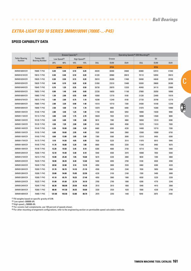
Ball Bearings
C
TIMKEN MACHINE TOOL CATALOG 161
EXTRA-LIGHT ISO 10 SERIES 3MM9100WI (7000E-...-P4S)
SPEED CAPABILITY DATA
Fafnir Bearing Number
Timken ISO Bearing Number
Grease Capacity(1) Operating Speeds(4) (DB Mounting)(5)
Low Speed(2) High Speed(3) Grease Oil
25% 40% 10% 15% DUL DUM DUH DUL DUM DUH
grams grams RPM RPM
3MM9100WICR 7000E-T-P4S 0.20 0.40 0.10 0.20 49320 36990 24660 83880 62910 41940
3MM9101WICR 7001E-T-P4S 0.30 0.40 0.10 0.20 41220 30960 20610 70110 52650 35010
3MM9102WICR 7002E-T-P4S 0.30 0.50 0.15 0.20 35010 26280 17460 59490 44640 29700
3MM9103WICR 7003E-T-P4S 0.40 0.70 0.20 0.30 31050 23310 15480 52830 39600 26280
3MM9104WICR 7004E-T-P4S 0.70 1.20 0.35 0.50 26730 20070 13320 45450 34110 22680
3MM9105WICR 7005E-T-P4S 0.90 1.40 0.40 0.60 22230 16650 11160 37800 28350 18990
3MM9106WICR 7006E-T-P4S 1.30 2.00 0.55 0.80 18360 13770 9180 31230 23400 15570
3MM9107WICR 7007E-T-P4S 1.60 2.60 0.75 1.10 16290 12240 8100 27720 20790 13770
3MM9108WICR 7008E-T-P4S 2.00 3.20 0.90 1.40 14310 10710 7200 24300 18180 12240
3MM9109WICR 7009E-T-P4S 2.50 4.00 1.10 1.70 12870 9000 6480 21870 16380 10980
3MM9110WICR 7010E-T-P4S 2.80 4.40 1.25 1.90 11700 8820 5850 19890 15030 9990
3MM9111WICR 7011E-T-P4S 4.00 6.40 1.75 2.70 10620 7920 5310 18090 13500 9000
3MM9112WICR 7012E-T-P4S 4.20 6.80 1.90 2.80 9810 7380 4860 16650 12510 8280
3MM9113WICR 7013E-T-P4S 4.50 7.20 2.00 3.00 9180 6840 4590 15570 11610 7830
3MM9114WICR 7014E-T-P4S 6.30 10.00 2.80 4.20 8460 6300 4230 14400 10710 7200
3MM9115WICR 7015E-T-P4S 6.60 10.60 2.95 4.40 7920 5940 3960 13500 10080 6750
3MM9116WICR 7016E-T-P4S 8.60 13.80 3.85 5.80 7380 5580 3690 12510 9450 6300
3MM9117WICR 7017E-T-P4S 9.10 14.50 4.05 6.00 7020 5220 3510 11970 8910 5940
3MM9118WICR 7018E-T-P4S 11.70 18.80 5.20 7.80 6660 4950 3330 11340 8460 5670
3MM9119WICR 7019E-T-P4S 12.20 19.50 5.45 8.10 6300 4680 3150 10710 7920 5400
3MM9120WICR 7020E-T-P4S 12.10 19.40 5.40 8.10 5940 4500 2970 10080 7650 5040
3MM9121WICR 7021E-T-P4S 15.90 25.40 7.05 10.60 5670 4230 2880 9630 7200 4860
3MM9122WICR 7022E-T-P4S 18.90 30.20 8.40 12.60 5400 4050 2700 9180 6930 4590
3MM9124WICR 7024E-T-P4S 20.50 32.80 9.10 13.70 4950 3690 2520 8460 6300 4320
3MM9126WICR 7026E-T-P4S 31.70 50.70 14.10 21.10 4590 3420 2340 7830 5850 3960
3MM9128WICR 7028E-T-P4S 33.80 54.00 15.05 22.50 4230 3150 2160 7200 5400 3690
3MM9130WICR 7030E-T-P4S 41.10 65.70 18.25 27.40 4050 3060 1980 6930 5220 3330
3MM9132WICR 7032E-T-P4S 51.00 81.60 22.70 34.10 3780 2790 1890 6390 4770 3240
3MM9134WICR 7034E-T-P4S 66.30 106.00 29.50 44.20 3510 2610 1800 5940 4410 3060
3MM9136WICR 7036E-T-P4S 88.40 141.50 39.35 59.00 3330 2520 1620 5580 4230 2790
3MM9140WICR 7040E-T-P4S 121.00 193.50 53.80 80.70 2970 2250 1440 5040 3870 2430
(1) Fill weights based on specific gravity of 0.99.(2) Low speed <500000 dN.(3) High speed > 500000 dN.(4) For ceramic ball complements, use 120 percent of speeds shown.(5) For other mounting arrangement configurations, refer to the engineering section on permissible speed calculation methods.
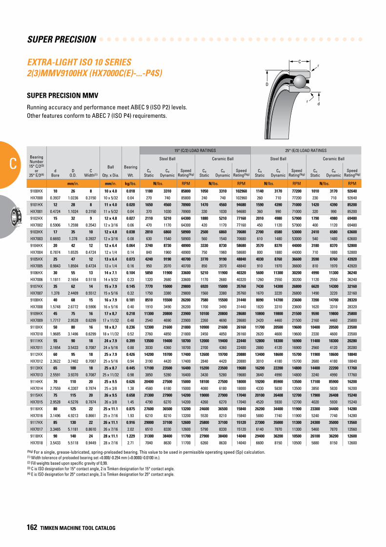
SUPER PRECISION
C
162 TIMKEN MACHINE TOOL CATALOG
C
D
r
dr
EXTRA-LIGHT ISO 10 SERIES 2(3)MMV9100HX (HX7000C(E)-...-P4S)
SUPER PRECISION MMV
Running accuracy and performance meet ABEC 9 (ISO P2) levels. Other features conform to ABEC 7 (ISO P4) requirements.
BearingNumber15° C/2(3)
or25° E/3(4)
dBore
DO.D.
CWidth(1)
Ball Bearing
15° (C/2) LOAD RATINGS 25° (E/3) LOAD RATINGS
rRad.(2)
Suggested Shoulder Diameters Shaft Diameter Mounting Fits
FIXED FLOATING
Steel Ball Ceramic Ball Steel Ball Ceramic Ball Housing Bore (Stationary) Mounting Fits Housing Bore
(Stationary) Mounting Fits
CoStatic
CeDynamic
SpeedRating(Ng)
CoStatic
CeDynamic
SpeedRating(Ng)
CoStatic
CeDynamic
SpeedRating(Ng)
CoStatic
CeDynamic
SpeedRating(Ng)
Shaft Housing
Qty. x Dia. Wt. Max. Min. Max. Min. Max. Min. Loose Tight Max. Min. Tight Loose Max. Min. Loose Loose
mm/in. mm/in. kg/lbs. N/lbs. RPM N/lbs. RPM N/lbs. RPM N/lbs. RPM mm/in. mm/in. mm/in. mm/in. mm/in. mm/in. mm/in. mm/in. mm/in.
9100HX 10 26 8 10 x 4.0 0.018 1180 3310 85800 1050 3310 102960 1140 3170 77200 1010 3170 92640 0.3 13.6 13.3 23.2 23 10.000 9.995 0.005 0.004 26.005 26.000 0.000 0.010 26.010 26.005 0.015 0.005
HX7000 0.3937 1.0236 0.3150 10 x 5/32 0.04 270 740 85800 240 740 102960 260 710 77200 230 710 92640 0.012 0.54 0.53 0.92 0.91 0.39370 0.39350 0.00020 0.00015 1.02380 1.02360 0.00000 0.00040 1.02400 1.02380 0.00060 0.00020
9101HX 12 28 8 11 x 4.0 0.020 1650 4560 78900 1470 4560 94680 1590 4390 71000 1420 4390 85200 0.3 16.1 15.9 25.5 25.3 12.000 11.995 0.005 0.004 28.005 28.000 0.000 0.010 28.010 28.005 0.015 0.005
HX7001 0.4724 1.1024 0.3150 11 x 5/32 0.04 370 1030 78900 330 1030 94680 360 990 71000 320 990 85200 0.012 0.64 0.63 1.01 1.00 0.47240 0.47220 0.00020 0.00015 1.10260 1.10240 0.00000 0.00040 1.10280 1.10260 0.00060 0.00020
9102HX 15 32 9 12 x 4.8 0.027 2110 5210 64300 1880 5210 77160 2010 4980 57900 1790 4980 69480 0.3 19.2 18.9 28.6 28.3 15.000 14.995 0.005 0.004 32.005 32.000 0.000 0.011 32.010 32.005 0.016 0.005
HX7002 0.5906 1.2598 0.3543 12 x 3/16 0.06 470 1170 64300 420 1170 77160 450 1120 57900 400 1120 69480 0.012 0.76 0.75 1.13 1.12 0.59060 0.59040 0.00020 0.00015 1.26000 1.25980 0.00000 0.00045 1.26020 1.26000 0.00070 0.00020
9103HX 17 35 10 12 x 4.8 0.038 2810 6860 58900 2500 6860 70680 2700 6580 53000 2410 6580 63600 0.3 21.7 21.5 31.1 30.9 17.000 16.995 0.005 0.004 35.006 35.000 0.000 0.012 35.010 35.005 0.016 0.005
HX7003 0.6693 1.378 0.3937 12 x 3/16 0.08 630 1540 58900 560 1540 70680 610 1480 53000 540 1480 63600 0.012 0.86 0.85 1.23 1.22 0.66930 0.66910 0.00020 0.00015 1.37830 1.37800 0.00000 0.00050 1.37840 1.37820 0.00070 0.00020
9104HX 20 42 12 12 x 6.4 0.064 3740 8730 48900 3330 8730 58680 3570 8370 44000 3180 8370 52800 0.6 25.0 24.8 37.7 37.5 20.000 19.995 0.005 0.005 42.006 42.000 0.000 0.012 42.010 42.005 0.016 0.005
HX7004 0.7874 1.6535 0.4724 12 x 1/4 0.14 840 1960 48900 750 1960 58680 800 1880 44000 710 1880 52800 0.024 0.99 0.98 1.49 1.48 0.78740 0.78720 0.00020 0.00020 1.65380 1.65350 0.00000 0.00050 1.65390 1.65370 0.00070 0.00020
9105HX 25 47 12 13 x 6.4 0.073 4240 9190 40700 3770 9190 48840 4030 8760 36600 3590 8760 43920 0.6 30.1 29.9 42.6 42.3 25.000 24.995 0.005 0.005 47.006 47.000 0.000 0.012 47.012 47.007 0.018 0.007
HX7005 0.9843 1.8504 0.4724 13 x 1/4 0.16 950 2070 40700 850 2070 48840 910 1970 36600 810 1970 43920 0.024 1.19 1.18 1.68 1.67 0.98430 0.98410 0.00020 0.00020 1.85070 1.85040 0.00000 0.00050 1.85090 1.85070 0.00080 0.00030
9106HX 30 55 13 14 x 7.1 0.104 5850 11900 33600 5210 11900 40320 5600 11300 30200 4990 11300 36240 1.0 36.20 35.90 50.7 50.4 30.000 29.995 0.005 0.005 55.008 55.000 0.000 0.015 55.012 55.007 0.019 0.007
HX7006 1.1811 2.1654 0.5118 14 x 9/32 0.23 1320 2680 33600 1170 2680 40320 1260 2550 30200 1120 2550 36240 0.039 1.43 1.42 2.00 1.99 1.18110 1.18090 0.00020 0.00020 2.16570 2.16540 0.00000 0.00060 2.16590 2.16570 0.00080 0.00030
9107HX 35 62 14 15 x 7.9 0.145 7770 15000 29800 6920 15000 35760 7430 14300 26800 6620 14300 32160 1.0 41.2 40.6 56.6 56.1 35.000 34.995 0.005 0.006 62.008 62.000 0.000 0.015 62.012 62.007 0.019 0.007
HX7007 1.378 2.4409 0.5512 15 x 5/16 0.32 1750 3380 29800 1560 3380 35760 1670 3220 26800 1490 3220 32160 0.039 1.62 1.60 2.23 2.21 1.37800 1.37780 0.00020 0.00025 2.44120 2.44090 0.00000 0.00060 2.44140 2.44120 0.00080 0.00030
9108HX 40 68 15 16 x 7.9 0.181 8510 15500 26200 7580 15500 31440 8090 14700 23600 7200 14700 28320 1.0 46.2 45.7 62.2 61.7 40.000 39.995 0.005 0.006 68.008 68.000 0.000 0.015 68.012 68.007 0.019 0.007
HX7008 1.5748 2.6772 0.5906 16 x 5/16 0.40 1910 3490 26200 1700 3490 31440 1820 3310 23600 1620 3310 28320 0.039 1.82 1.80 2.45 2.43 1.57480 1.57460 0.00020 0.00025 2.67750 2.67720 0.00000 0.00060 2.67770 2.67750 0.00080 0.00030
9109HX 45 75 16 17 x 8,7 0.218 11300 20800 23900 10100 20800 28680 10800 19800 21500 9590 19800 25800 1.0 51.8 51.3 69.3 68.8 45.000 44.995 0.005 0.006 75.008 75.000 0.000 0.015 75.014 75.009 0.022 0.009
HX7009 1.7717 2.9528 0.6299 17 x 11/32 0.48 2540 4690 23900 2260 4690 28680 2420 4460 21500 2160 4460 25800 0.039 2.04 2.02 2.73 2.71 1.7717 1.77150 0.00020 0.00025 2.95310 2.95280 0.00000 0.00060 2.95330 2.95310 0.00080 0.00030
9110HX 50 80 16 18 x 8,7 0.236 12300 21600 21800 10900 21600 26160 11700 20500 19600 10400 20500 23500 1.0 56.6 56.1 74.2 73.7 50.000 49.995 0.005 0.006 80.008 80.000 0.000 0.015 80.012 80.008 0.020 0.008
HX7010 1.9685 3.1496 0.6299 18 x 11/32 0.52 2760 4850 21800 2450 4850 26160 2620 4600 19600 2330 4600 23500 0.039 2.23 2.21 2.92 2.90 1.96850 1.96830 0.00020 0.00025 3.14990 3.14960 0.00000 0.00060 3.15010 3.14990 0.00080 0.00030
9111HX 55 90 18 24 x 7.9 0.399 13500 19400 18700 12000 19400 22440 12800 18300 16900 11400 18300 20280 1.0 62.7 62.2 83.3 82.8 55.000 54.995 0.005 0.007 90.008 90.000 0.000 0.016 90.015 90.007 0.023 0.007
HX7011 2.1654 3.5433 0.7087 24 x 5/16 0.88 3030 4360 18700 2700 4360 22400 2880 4120 16900 2560 4120 20280 0.039 2.47 2.45 3.28 3.26 2.16540 2.16520 0.00020 0.00030 3.54360 3.54330 0.00000 0.00060 3.54390 3.54360 0.00090 0.00030
9112HX 60 95 18 25 x 7.9 0.426 14200 19700 17400 12600 19700 20880 13400 18600 15700 11900 18600 18840 1.0 67.8 67.3 88.1 87.6 60.000 59.995 0.005 0.007 95.008 95.000 0.000 0.016 95.016 95.009 0.024 0.009
HX7012 2.3622 3.7402 0.7087 25 x 5/16 0.94 3190 4420 17400 2840 4420 20880 3010 4180 15700 2680 4180 18840 0.039 2.67 2.65 3.47 3.45 2.36220 2.36200 0.00020 0.00030 3.74050 3.74020 0.00000 0.00060 3.74080 3.74050 0.00090 0.00030
9113HX 65 100 18 25 x 8.7 0.445 17100 23500 16400 15200 23500 19680 16200 22200 14800 14400 22200 17760 1.0 72.6 72.1 93.2 92.7 65.000 64.995 0.005 0.007 100.008 100.000 0.000 0.016 100.018 100.010 0.025 0.010
HX7013 2.5591 3.9370 0.7087 25 x 11/32 0.98 3850 5280 16400 3430 5280 19680 3640 4990 14800 3240 4990 17760 0.039 2.86 2.84 3.67 3.65 2.55910 2.55890 0.00020 0.00030 3.93730 3.93700 0.00000 0.00060 3.93770 3.93740 0.00100 0.00040
9114HX 70 110 20 25 x 9.5 0.626 20400 27500 15000 18100 27500 18000 19200 85900 13500 17100 85900 16200 1.0 78.2 77.7 102.4 101.9 70.000 69.995 0.005 0.007 110.008 110.000 0.000 0.016 110.018 110.010 0.025 0.010
HX7014 2.7559 4.3307 0.7874 25 x 3/8 1.38 4580 6180 15000 4080 6180 18000 4330 5830 13500 3850 5830 16200 0.039 3.08 3.06 4.03 4.01 2.75590 2.75570 0.00020 0.00030 4.33100 4.33070 0.00000 0.000600 4.33140 4.33110 0.00100 0.00040
9115HX 75 115 20 26 x 9.5 0.658 21300 27900 14200 19000 27900 17040 20100 26408 12700 17900 26408 15240 1.0 83.4 82.7 107.3 106.6 75.005 74.995 0.005 0.012 115.008 115.000 0.000 0.016 115.019 115.011 0.026 0.010
HX7015 2.9528 4.5276 0.7874 26 x 3/8 1.45 4790 6270 14200 4260 6270 17040 4520 5930 12700 4020 5930 15240 0.039 3.29 3.26 4.23 4.20 2.95300 2.95260 0.00020 0.00050 4.52790 4.52760 0.00000 0.00060 4.52830 4.52800 0.00100 0.00040
9116HX 80 125 22 25 x 11.1 0.875 27600 36500 13200 24600 36500 15840 26200 34400 11900 23300 34400 14280 1.0 89.3 88.5 116.5 115.7 80.005 79.995 0.005 0.012 125.008 125.000 0.000 0.017 125.021 125.011 0.030 0.011
HX7016 3.1496 4.9213 0.8661 25 x 7/16 1.93 6210 8210 13200 5530 8210 15840 5880 7740 11900 5240 7740 14280 0.039 3.52 3.49 4.59 4.56 3.14980 3.14940 0.00020 0.00050 4.92160 4.92130 0.00000 0.00070 4.92210 4.92170 0.00120 0.00040
9117HX 85 130 22 26 x 11.1 0.916 29000 37100 12600 25800 37100 15120 27300 35000 11300 24300 35000 13560 1.0 94.9 94.1 122.1 121.3 85.005 84.995 0.005 0.012 130.009 130.000 0.000 0.018 130.020 130.010 0.029 0.010
HX7017 3.3465 5.1181 0.8610 26 x 7/16 2.02 6510 8330 12600 5790 8330 15120 6140 7870 11300 5460 7870 13560 0.039 3.74 3.71 4.81 4.78 3.34670 3.34630 0.00020 0.00050 5.11850 5.11810 0.00000 0.00070 5.11890 5.11850 0.00110 0.00040
9118HX 90 140 24 28 x 11.1 1.229 31300 38400 11700 27900 38400 14040 29400 36200 10500 26100 36200 12600 1.5 100.5 99.7 130.9 130.2 90.005 89.995 0.005 0.013 140.009 140.000 0.000 0.018 140.020 140.010 0.029 0.010
HX7018 3.5433 5.5118 0.9449 28 x 7/16 2.71 7040 8630 11700 6260 8630 14040 6600 8150 10500 5880 8150 12600 0.059 3.96 3.93 5.16 5.13 3.54350 3.54310 0.00020 0.00050 5.51220 5.51180 0.00000 0.00070 5.51260 5.51220 0.00110 0.00040
(Ng) For a single, grease-lubricated, spring-preloaded bearing. This value to be used in permissible operating speed (Sp) calculation.(1) Width tolerance of preloaded bearing set +0.000/-0.254 mm (+0.0000/-0.0100 in.).(2) Fill weights based upon specific gravity of 0,99.(3) C is ISO designation for 15° contact angle, 2 is Timken designation for 15° contact angle.(4) E is ISO designation for 25° contact angle, 3 is Timken designation for 25° contact angle.
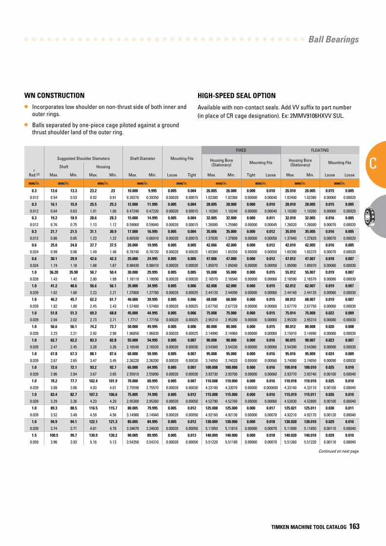
Ball Bearings
C
TIMKEN MACHINE TOOL CATALOG 163
BearingNumber15° C/2(3)
or25° E/3(4)
dBore
DO.D.
CWidth(1)
Ball Bearing
15° (C/2) LOAD RATINGS 25° (E/3) LOAD RATINGS
rRad.(2)
Suggested Shoulder Diameters Shaft Diameter Mounting Fits
FIXED FLOATING
Steel Ball Ceramic Ball Steel Ball Ceramic Ball Housing Bore (Stationary) Mounting Fits Housing Bore
(Stationary) Mounting Fits
CoStatic
CeDynamic
SpeedRating(Ng)
CoStatic
CeDynamic
SpeedRating(Ng)
CoStatic
CeDynamic
SpeedRating(Ng)
CoStatic
CeDynamic
SpeedRating(Ng)
Shaft Housing
Qty. x Dia. Wt. Max. Min. Max. Min. Max. Min. Loose Tight Max. Min. Tight Loose Max. Min. Loose Loose
mm/in. mm/in. kg/lbs. N/lbs. RPM N/lbs. RPM N/lbs. RPM N/lbs. RPM mm/in. mm/in. mm/in. mm/in. mm/in. mm/in. mm/in. mm/in. mm/in.
9100HX 10 26 8 10 x 4.0 0.018 1180 3310 85800 1050 3310 102960 1140 3170 77200 1010 3170 92640 0.3 13.6 13.3 23.2 23 10.000 9.995 0.005 0.004 26.005 26.000 0.000 0.010 26.010 26.005 0.015 0.005
HX7000 0.3937 1.0236 0.3150 10 x 5/32 0.04 270 740 85800 240 740 102960 260 710 77200 230 710 92640 0.012 0.54 0.53 0.92 0.91 0.39370 0.39350 0.00020 0.00015 1.02380 1.02360 0.00000 0.00040 1.02400 1.02380 0.00060 0.00020
9101HX 12 28 8 11 x 4.0 0.020 1650 4560 78900 1470 4560 94680 1590 4390 71000 1420 4390 85200 0.3 16.1 15.9 25.5 25.3 12.000 11.995 0.005 0.004 28.005 28.000 0.000 0.010 28.010 28.005 0.015 0.005
HX7001 0.4724 1.1024 0.3150 11 x 5/32 0.04 370 1030 78900 330 1030 94680 360 990 71000 320 990 85200 0.012 0.64 0.63 1.01 1.00 0.47240 0.47220 0.00020 0.00015 1.10260 1.10240 0.00000 0.00040 1.10280 1.10260 0.00060 0.00020
9102HX 15 32 9 12 x 4.8 0.027 2110 5210 64300 1880 5210 77160 2010 4980 57900 1790 4980 69480 0.3 19.2 18.9 28.6 28.3 15.000 14.995 0.005 0.004 32.005 32.000 0.000 0.011 32.010 32.005 0.016 0.005
HX7002 0.5906 1.2598 0.3543 12 x 3/16 0.06 470 1170 64300 420 1170 77160 450 1120 57900 400 1120 69480 0.012 0.76 0.75 1.13 1.12 0.59060 0.59040 0.00020 0.00015 1.26000 1.25980 0.00000 0.00045 1.26020 1.26000 0.00070 0.00020
9103HX 17 35 10 12 x 4.8 0.038 2810 6860 58900 2500 6860 70680 2700 6580 53000 2410 6580 63600 0.3 21.7 21.5 31.1 30.9 17.000 16.995 0.005 0.004 35.006 35.000 0.000 0.012 35.010 35.005 0.016 0.005
HX7003 0.6693 1.378 0.3937 12 x 3/16 0.08 630 1540 58900 560 1540 70680 610 1480 53000 540 1480 63600 0.012 0.86 0.85 1.23 1.22 0.66930 0.66910 0.00020 0.00015 1.37830 1.37800 0.00000 0.00050 1.37840 1.37820 0.00070 0.00020
9104HX 20 42 12 12 x 6.4 0.064 3740 8730 48900 3330 8730 58680 3570 8370 44000 3180 8370 52800 0.6 25.0 24.8 37.7 37.5 20.000 19.995 0.005 0.005 42.006 42.000 0.000 0.012 42.010 42.005 0.016 0.005
HX7004 0.7874 1.6535 0.4724 12 x 1/4 0.14 840 1960 48900 750 1960 58680 800 1880 44000 710 1880 52800 0.024 0.99 0.98 1.49 1.48 0.78740 0.78720 0.00020 0.00020 1.65380 1.65350 0.00000 0.00050 1.65390 1.65370 0.00070 0.00020
9105HX 25 47 12 13 x 6.4 0.073 4240 9190 40700 3770 9190 48840 4030 8760 36600 3590 8760 43920 0.6 30.1 29.9 42.6 42.3 25.000 24.995 0.005 0.005 47.006 47.000 0.000 0.012 47.012 47.007 0.018 0.007
HX7005 0.9843 1.8504 0.4724 13 x 1/4 0.16 950 2070 40700 850 2070 48840 910 1970 36600 810 1970 43920 0.024 1.19 1.18 1.68 1.67 0.98430 0.98410 0.00020 0.00020 1.85070 1.85040 0.00000 0.00050 1.85090 1.85070 0.00080 0.00030
9106HX 30 55 13 14 x 7.1 0.104 5850 11900 33600 5210 11900 40320 5600 11300 30200 4990 11300 36240 1.0 36.20 35.90 50.7 50.4 30.000 29.995 0.005 0.005 55.008 55.000 0.000 0.015 55.012 55.007 0.019 0.007
HX7006 1.1811 2.1654 0.5118 14 x 9/32 0.23 1320 2680 33600 1170 2680 40320 1260 2550 30200 1120 2550 36240 0.039 1.43 1.42 2.00 1.99 1.18110 1.18090 0.00020 0.00020 2.16570 2.16540 0.00000 0.00060 2.16590 2.16570 0.00080 0.00030
9107HX 35 62 14 15 x 7.9 0.145 7770 15000 29800 6920 15000 35760 7430 14300 26800 6620 14300 32160 1.0 41.2 40.6 56.6 56.1 35.000 34.995 0.005 0.006 62.008 62.000 0.000 0.015 62.012 62.007 0.019 0.007
HX7007 1.378 2.4409 0.5512 15 x 5/16 0.32 1750 3380 29800 1560 3380 35760 1670 3220 26800 1490 3220 32160 0.039 1.62 1.60 2.23 2.21 1.37800 1.37780 0.00020 0.00025 2.44120 2.44090 0.00000 0.00060 2.44140 2.44120 0.00080 0.00030
9108HX 40 68 15 16 x 7.9 0.181 8510 15500 26200 7580 15500 31440 8090 14700 23600 7200 14700 28320 1.0 46.2 45.7 62.2 61.7 40.000 39.995 0.005 0.006 68.008 68.000 0.000 0.015 68.012 68.007 0.019 0.007
HX7008 1.5748 2.6772 0.5906 16 x 5/16 0.40 1910 3490 26200 1700 3490 31440 1820 3310 23600 1620 3310 28320 0.039 1.82 1.80 2.45 2.43 1.57480 1.57460 0.00020 0.00025 2.67750 2.67720 0.00000 0.00060 2.67770 2.67750 0.00080 0.00030
9109HX 45 75 16 17 x 8,7 0.218 11300 20800 23900 10100 20800 28680 10800 19800 21500 9590 19800 25800 1.0 51.8 51.3 69.3 68.8 45.000 44.995 0.005 0.006 75.008 75.000 0.000 0.015 75.014 75.009 0.022 0.009
HX7009 1.7717 2.9528 0.6299 17 x 11/32 0.48 2540 4690 23900 2260 4690 28680 2420 4460 21500 2160 4460 25800 0.039 2.04 2.02 2.73 2.71 1.7717 1.77150 0.00020 0.00025 2.95310 2.95280 0.00000 0.00060 2.95330 2.95310 0.00080 0.00030
9110HX 50 80 16 18 x 8,7 0.236 12300 21600 21800 10900 21600 26160 11700 20500 19600 10400 20500 23500 1.0 56.6 56.1 74.2 73.7 50.000 49.995 0.005 0.006 80.008 80.000 0.000 0.015 80.012 80.008 0.020 0.008
HX7010 1.9685 3.1496 0.6299 18 x 11/32 0.52 2760 4850 21800 2450 4850 26160 2620 4600 19600 2330 4600 23500 0.039 2.23 2.21 2.92 2.90 1.96850 1.96830 0.00020 0.00025 3.14990 3.14960 0.00000 0.00060 3.15010 3.14990 0.00080 0.00030
9111HX 55 90 18 24 x 7.9 0.399 13500 19400 18700 12000 19400 22440 12800 18300 16900 11400 18300 20280 1.0 62.7 62.2 83.3 82.8 55.000 54.995 0.005 0.007 90.008 90.000 0.000 0.016 90.015 90.007 0.023 0.007
HX7011 2.1654 3.5433 0.7087 24 x 5/16 0.88 3030 4360 18700 2700 4360 22400 2880 4120 16900 2560 4120 20280 0.039 2.47 2.45 3.28 3.26 2.16540 2.16520 0.00020 0.00030 3.54360 3.54330 0.00000 0.00060 3.54390 3.54360 0.00090 0.00030
9112HX 60 95 18 25 x 7.9 0.426 14200 19700 17400 12600 19700 20880 13400 18600 15700 11900 18600 18840 1.0 67.8 67.3 88.1 87.6 60.000 59.995 0.005 0.007 95.008 95.000 0.000 0.016 95.016 95.009 0.024 0.009
HX7012 2.3622 3.7402 0.7087 25 x 5/16 0.94 3190 4420 17400 2840 4420 20880 3010 4180 15700 2680 4180 18840 0.039 2.67 2.65 3.47 3.45 2.36220 2.36200 0.00020 0.00030 3.74050 3.74020 0.00000 0.00060 3.74080 3.74050 0.00090 0.00030
9113HX 65 100 18 25 x 8.7 0.445 17100 23500 16400 15200 23500 19680 16200 22200 14800 14400 22200 17760 1.0 72.6 72.1 93.2 92.7 65.000 64.995 0.005 0.007 100.008 100.000 0.000 0.016 100.018 100.010 0.025 0.010
HX7013 2.5591 3.9370 0.7087 25 x 11/32 0.98 3850 5280 16400 3430 5280 19680 3640 4990 14800 3240 4990 17760 0.039 2.86 2.84 3.67 3.65 2.55910 2.55890 0.00020 0.00030 3.93730 3.93700 0.00000 0.00060 3.93770 3.93740 0.00100 0.00040
9114HX 70 110 20 25 x 9.5 0.626 20400 27500 15000 18100 27500 18000 19200 85900 13500 17100 85900 16200 1.0 78.2 77.7 102.4 101.9 70.000 69.995 0.005 0.007 110.008 110.000 0.000 0.016 110.018 110.010 0.025 0.010
HX7014 2.7559 4.3307 0.7874 25 x 3/8 1.38 4580 6180 15000 4080 6180 18000 4330 5830 13500 3850 5830 16200 0.039 3.08 3.06 4.03 4.01 2.75590 2.75570 0.00020 0.00030 4.33100 4.33070 0.00000 0.000600 4.33140 4.33110 0.00100 0.00040
9115HX 75 115 20 26 x 9.5 0.658 21300 27900 14200 19000 27900 17040 20100 26408 12700 17900 26408 15240 1.0 83.4 82.7 107.3 106.6 75.005 74.995 0.005 0.012 115.008 115.000 0.000 0.016 115.019 115.011 0.026 0.010
HX7015 2.9528 4.5276 0.7874 26 x 3/8 1.45 4790 6270 14200 4260 6270 17040 4520 5930 12700 4020 5930 15240 0.039 3.29 3.26 4.23 4.20 2.95300 2.95260 0.00020 0.00050 4.52790 4.52760 0.00000 0.00060 4.52830 4.52800 0.00100 0.00040
9116HX 80 125 22 25 x 11.1 0.875 27600 36500 13200 24600 36500 15840 26200 34400 11900 23300 34400 14280 1.0 89.3 88.5 116.5 115.7 80.005 79.995 0.005 0.012 125.008 125.000 0.000 0.017 125.021 125.011 0.030 0.011
HX7016 3.1496 4.9213 0.8661 25 x 7/16 1.93 6210 8210 13200 5530 8210 15840 5880 7740 11900 5240 7740 14280 0.039 3.52 3.49 4.59 4.56 3.14980 3.14940 0.00020 0.00050 4.92160 4.92130 0.00000 0.00070 4.92210 4.92170 0.00120 0.00040
9117HX 85 130 22 26 x 11.1 0.916 29000 37100 12600 25800 37100 15120 27300 35000 11300 24300 35000 13560 1.0 94.9 94.1 122.1 121.3 85.005 84.995 0.005 0.012 130.009 130.000 0.000 0.018 130.020 130.010 0.029 0.010
HX7017 3.3465 5.1181 0.8610 26 x 7/16 2.02 6510 8330 12600 5790 8330 15120 6140 7870 11300 5460 7870 13560 0.039 3.74 3.71 4.81 4.78 3.34670 3.34630 0.00020 0.00050 5.11850 5.11810 0.00000 0.00070 5.11890 5.11850 0.00110 0.00040
9118HX 90 140 24 28 x 11.1 1.229 31300 38400 11700 27900 38400 14040 29400 36200 10500 26100 36200 12600 1.5 100.5 99.7 130.9 130.2 90.005 89.995 0.005 0.013 140.009 140.000 0.000 0.018 140.020 140.010 0.029 0.010
HX7018 3.5433 5.5118 0.9449 28 x 7/16 2.71 7040 8630 11700 6260 8630 14040 6600 8150 10500 5880 8150 12600 0.059 3.96 3.93 5.16 5.13 3.54350 3.54310 0.00020 0.00050 5.51220 5.51180 0.00000 0.00070 5.51260 5.51220 0.00110 0.00040
Continued on next page.
WN CONSTRUCTION
• Incorporates low shoulder on non-thrust side of both inner and outer rings.
• Balls separated by one-piece cage piloted against a ground thrust shoulder land of the outer ring.
HIGH-SPEED SEAL OPTION
Available with non-contact seals. Add VV suffix to part number (in place of CR cage designation). Ex: 2MMV9106HXVV SUL.

SUPER PRECISION
C
164 TIMKEN MACHINE TOOL CATALOG
C
D
r
dr
(Ng) For a single, grease-lubricated, spring-preloaded bearing. This value to be used in permissible operating speed (Sp) calculation.(1) Width tolerance of preloaded bearing set +0.000/-0.254 mm (+0.0000/-0.0100 in.).(2) Fill weights based upon specific gravity of 0,99.(3) C is ISO designation for 15° contact angle, 2 is Timken designation for 15° contact angle.(4) E is ISO designation for 25° contact angle, 3 is Timken designation for 25° contact angle.
BearingNumber15° C/2(3)
or25° E/3(4)
dBore
DO.D.
CWidth(1)
Ball Bearing
15° (C/2) LOAD RATINGS 25° (E/3) LOAD RATINGS
rRad.(2)
Suggested Shoulder Diameters Shaft Diameter Mounting Fits
FIXED FLOATING
Steel Ball Ceramic Ball Steel Ball Ceramic Ball Housing Bore (Stationary) Mounting Fits Housing Bore
(Stationary) Mounting Fits
CoStatic
CeDynamic
SpeedRating(Ng)
CoStatic
CeDynamic
SpeedRating(Ng)
CoStatic
CeDynamic
SpeedRating(Ng)
CoStatic
CeDynamic
SpeedRating(Ng)
Shaft Housing
Qty. x Dia. Wt. Max. Min. Max. Min. Max. Min. Loose Tight Max. Min. Tight Loose Max. Min. Loose Loose
mm/in. mm/in. kg/lbs. N/lbs. RPM N/lbs. RPM N/lbs. RPM N/lbs. RPM mm/in. mm/in. mm/in. mm/in. mm/in. mm/in. mm/in. mm/in. mm/in.
9120HX 100 150 24 27 x 12.7 1.288 39300 48200 10800 35000 48200 12960 37000 45500 9700 33000 45500 11640 1.5 110.6 109.9 140.8 140.1 100.005 99.995 0.005 0.013 150.009 150.000 0.000 0.018 150.023 150.012 0.032 0.012
HX7020 3.9370 5.9055 0.9449 27 x 1/2 2.84 8840 10800 10800 7870 10800 12960 8330 10200 9700 7410 10200 11640 0.059 4.36 4.33 5.55 5.52 3.93720 3.93680 0.00020 0.00050 5.90590 5.90550 0.00000 0.00070 5.90640 5.90600 0.00120 0.00050
9122HX 110 170 28 30 x 12.7 2.132 43800 50400 9500 38900 50400 11400 40800 47500 8560 36300 47500 10270 2.0 123.1 122.3 158.4 157.6 110.005 109.995 0.005 0.013 170.010 170.000 0.000 0.020 170.022 170.012 0.032 0.012
HX7022 4.3307 6.6929 1.1024 30 x 1/2 4.70 9840 113000 9500 8760 113000 11400 9180 10700 8560 8170 10700 10270 0.079 4.85 4.82 6.24 6.21 4.33090 4.33050 0.00020 0.00050 6.69330 6.69290 0.00000 0.00080 6.69380 6.69340 0.00130 0.00050
9124HX 120 180 28 29 x 14.3 2.218 53700 61700 8900 47800 61700 10680 50200 58100 8030 44700 58100 9640 2.0 133.2 132.5 168.3 167.5 120.005 119.995 0.005 0.013 180.010 180.000 0.000 0.020 180.022 180.012 0.032 0.012
HX7024 4.7244 7.0866 1.1024 29 x 9/16 4.89 12100 139000 8900 10700 139000 10680 11300 13100 8030 10000 13100 9640 0.079 5.25 5.22 6.63 6.60 4.72460 4.72420 0.00020 0.00050 7.08700 7.08660 0.00000 0.00080 7.08750 7.08710 0.00130 0.00050
EXTRA-LIGHT ISO 10 SERIES 2(3)MMV9100HX (HX7000C(E)-...-P4S) – continued
SUPER PRECISION MMV
Running accuracy and performance meet ABEC 9 (ISO P2) levels. Other features conform to ABEC 7 (ISO P4) requirements.
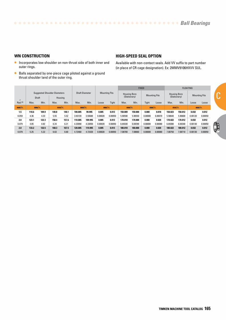
Ball Bearings
C
TIMKEN MACHINE TOOL CATALOG 165
BearingNumber15° C/2(3)
or25° E/3(4)
dBore
DO.D.
CWidth(1)
Ball Bearing
15° (C/2) LOAD RATINGS 25° (E/3) LOAD RATINGS
rRad.(2)
Suggested Shoulder Diameters Shaft Diameter Mounting Fits
FIXED FLOATING
Steel Ball Ceramic Ball Steel Ball Ceramic Ball Housing Bore (Stationary) Mounting Fits Housing Bore
(Stationary) Mounting Fits
CoStatic
CeDynamic
SpeedRating(Ng)
CoStatic
CeDynamic
SpeedRating(Ng)
CoStatic
CeDynamic
SpeedRating(Ng)
CoStatic
CeDynamic
SpeedRating(Ng)
Shaft Housing
Qty. x Dia. Wt. Max. Min. Max. Min. Max. Min. Loose Tight Max. Min. Tight Loose Max. Min. Loose Loose
mm/in. mm/in. kg/lbs. N/lbs. RPM N/lbs. RPM N/lbs. RPM N/lbs. RPM mm/in. mm/in. mm/in. mm/in. mm/in. mm/in. mm/in. mm/in. mm/in.
9120HX 100 150 24 27 x 12.7 1.288 39300 48200 10800 35000 48200 12960 37000 45500 9700 33000 45500 11640 1.5 110.6 109.9 140.8 140.1 100.005 99.995 0.005 0.013 150.009 150.000 0.000 0.018 150.023 150.012 0.032 0.012
HX7020 3.9370 5.9055 0.9449 27 x 1/2 2.84 8840 10800 10800 7870 10800 12960 8330 10200 9700 7410 10200 11640 0.059 4.36 4.33 5.55 5.52 3.93720 3.93680 0.00020 0.00050 5.90590 5.90550 0.00000 0.00070 5.90640 5.90600 0.00120 0.00050
9122HX 110 170 28 30 x 12.7 2.132 43800 50400 9500 38900 50400 11400 40800 47500 8560 36300 47500 10270 2.0 123.1 122.3 158.4 157.6 110.005 109.995 0.005 0.013 170.010 170.000 0.000 0.020 170.022 170.012 0.032 0.012
HX7022 4.3307 6.6929 1.1024 30 x 1/2 4.70 9840 113000 9500 8760 113000 11400 9180 10700 8560 8170 10700 10270 0.079 4.85 4.82 6.24 6.21 4.33090 4.33050 0.00020 0.00050 6.69330 6.69290 0.00000 0.00080 6.69380 6.69340 0.00130 0.00050
9124HX 120 180 28 29 x 14.3 2.218 53700 61700 8900 47800 61700 10680 50200 58100 8030 44700 58100 9640 2.0 133.2 132.5 168.3 167.5 120.005 119.995 0.005 0.013 180.010 180.000 0.000 0.020 180.022 180.012 0.032 0.012
HX7024 4.7244 7.0866 1.1024 29 x 9/16 4.89 12100 139000 8900 10700 139000 10680 11300 13100 8030 10000 13100 9640 0.079 5.25 5.22 6.63 6.60 4.72460 4.72420 0.00020 0.00050 7.08700 7.08660 0.00000 0.00080 7.08750 7.08710 0.00130 0.00050
WN CONSTRUCTION
• Incorporates low shoulder on non-thrust side of both inner and outer rings.
• Balls separated by one-piece cage piloted against a ground thrust shoulder land of the outer ring.
HIGH-SPEED SEAL OPTION
Available with non-contact seals. Add VV suffix to part number (in place of CR cage designation). Ex: 2MMV9106HXVV SUL.
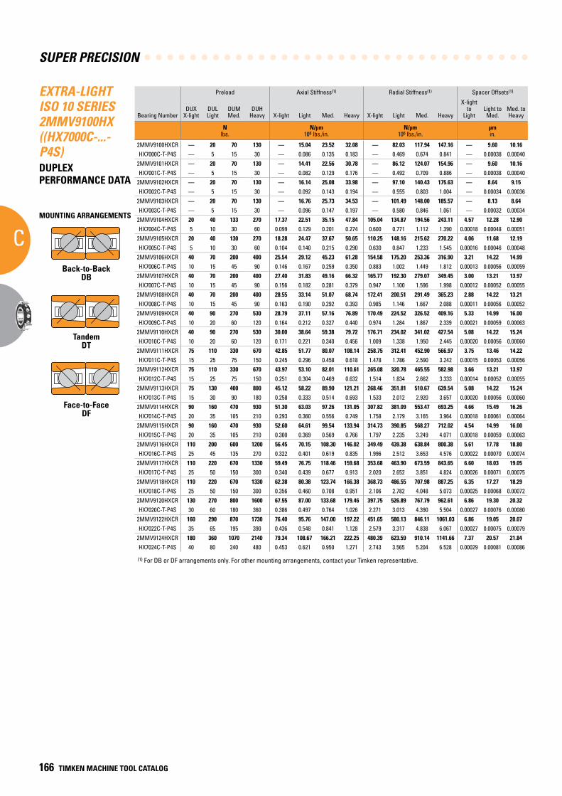
SUPER PRECISION
C
166 TIMKEN MACHINE TOOL CATALOG
EXTRA-LIGHT ISO 10 SERIES 2MMV9100HX ((HX7000C-...-P4S)DUPLEX PERFORMANCE DATA
Preload Axial Stiffness(1) Radial Stiffness(1) Spacer Offsets(1)
Bearing NumberDUX
X-lightDULLight
DUMMed.
DUHHeavy X-light Light Med. Heavy X-light Light Med. Heavy
X-light to
LightLight to
Med.Med. toHeavy
N lbs.
N/µm 106 lbs./in.
N/µm 106 lbs./in.
µm in.
2MMV9100HXCR — 20 70 130 — 15.04 23.52 32.08 — 82.03 117.94 147.16 — 9.60 10.16HX7000C-T-P4S — 5 15 30 — 0.086 0.135 0.183 — 0.469 0.674 0.841 — 0.00038 0.00040
2MMV9101HXCR — 20 70 130 — 14.41 22.56 30.78 — 86.12 124.07 154.96 — 9.60 10.16HX7001C-T-P4S — 5 15 30 — 0.082 0.129 0.176 — 0.492 0.709 0.886 — 0.00038 0.00040
2MMV9102HXCR — 20 70 130 — 16.14 25.08 33.98 — 97.10 140.43 175.63 — 8.64 9.15HX7002C-T-P4S — 5 15 30 — 0.092 0.143 0.194 — 0.555 0.803 1.004 — 0.00034 0.00036
2MMV9103HXCR — 20 70 130 — 16.76 25.73 34.53 — 101.49 148.00 185.57 — 8.13 8.64HX7003C-T-P4S — 5 15 30 — 0.096 0.147 0.197 — 0.580 0.846 1.061 — 0.00032 0.00034
2MMV9104HXCR 20 40 133 270 17.37 22.51 35.15 47.84 105.04 134.87 194.56 243.11 4.57 12.28 12.90HX7004C-T-P4S 5 10 30 60 0.099 0.129 0.201 0.274 0.600 0.771 1.112 1.390 0.00018 0.00048 0.00051
2MMV9105HXCR 20 40 130 270 18.28 24.47 37.67 50.65 110.25 148.16 215.62 270.22 4.06 11.68 12.19HX7005C-T-P4S 5 10 30 60 0.104 0.140 0.215 0.290 0.630 0.847 1.233 1.545 0.00016 0.00046 0.00048
2MMV9106HXCR 40 70 200 400 25.54 29.12 45.23 61.28 154.58 175.20 253.36 316.90 3.21 14.22 14.99HX7006C-T-P4S 10 15 45 90 0.146 0.167 0.259 0.350 0.883 1.002 1.449 1.812 0.00013 0.00056 0.00059
2MMV9107HXCR 40 70 200 400 27.40 31.83 49.16 66.32 165.77 192.30 279.07 349.45 3.00 13.21 13.97HX7007C-T-P4S 10 15 45 90 0.156 0.182 0.281 0.379 0.947 1.100 1.596 1.998 0.00012 0.00052 0.00055
2MMV9108HXCR 40 70 200 400 28.55 33.14 51.07 68.74 172.41 200.51 291.49 365.23 2.88 14.22 13.21HX7008C-T-P4S 10 15 45 90 0.163 0.190 0.292 0.393 0.985 1.146 1.667 2.088 0.00011 0.00056 0.00052
2MMV9109HXCR 40 90 270 530 28.79 37.11 57.16 76.89 170.49 224.52 326.52 409.16 5.33 14.99 16.00HX7009C-T-P4S 10 20 60 120 0.164 0.212 0.327 0.440 0.974 1.284 1.867 2.339 0.00021 0.00059 0.00063
2MMV9110HXCR 40 90 270 530 30.00 38.64 59.38 79.72 176.71 234.02 341.02 427.54 5.08 14.22 15.24HX7010C-T-P4S 10 20 60 120 0.171 0.221 0.340 0.456 1.009 1.338 1.950 2.445 0.00020 0.00056 0.00060
2MMV9111HXCR 75 110 330 670 42.85 51.77 80.07 108.14 258.75 312.41 452.90 566.97 3.75 13.46 14.22HX7011C-T-P4S 15 25 75 150 0.245 0.296 0.458 0.618 1.478 1.786 2.590 3.242 0.00015 0.00053 0.00056
2MMV9112HXCR 75 110 330 670 43.97 53.10 82.01 110.61 265.08 320.78 465.55 582.98 3.66 13.21 13.97HX7012C-T-P4S 15 25 75 150 0.251 0.304 0.469 0.632 1.514 1.834 2.662 3.333 0.00014 0.00052 0.00055
2MMV9113HXCR 75 130 400 800 45.12 58.22 89.90 121.21 268.46 351.81 510.67 639.54 5.08 14.22 15.24HX7013C-T-P4S 15 30 90 180 0.258 0.333 0.514 0.693 1.533 2.012 2.920 3.657 0.00020 0.00056 0.00060
2MMV9114HXCR 90 160 470 930 51.30 63.03 97.26 131.05 307.82 381.09 553.47 693.25 4.66 15.49 16.26HX7014C-T-P4S 20 35 105 210 0.293 0.360 0.556 0.749 1.758 2.179 3.165 3.964 0.00018 0.00061 0.00064
2MMV9115HXCR 90 160 470 930 52.60 64.61 99.54 133.94 314.73 390.85 568.27 712.02 4.54 14.99 16.00HX7015C-T-P4S 20 35 105 210 0.300 0.369 0.569 0.766 1.797 2.235 3.249 4.071 0.00018 0.00059 0.00063
2MMV9116HXCR 110 200 600 1200 56.45 70.15 108.30 146.02 349.49 439.38 638.84 800.38 5.61 17.78 18.80HX7016C-T-P4S 25 45 135 270 0.322 0.401 0.619 0.835 1.996 2.512 3.653 4.576 0.00022 0.00070 0.00074
2MMV9117HXCR 110 220 670 1330 59.49 76.75 118.46 159.68 353.68 463.90 673.59 843.65 6.60 18.03 19.05HX7017C-T-P4S 25 50 150 300 0.340 0.439 0.677 0.913 2.020 2.652 3.851 4.824 0.00026 0.00071 0.00075
2MMV9118HXCR 110 220 670 1330 62.38 80.38 123.74 166.38 368.73 486.55 707.98 887.25 6.35 17.27 18.29HX7018C-T-P4S 25 50 150 300 0.356 0.460 0.708 0.951 2.106 2.782 4.048 5.073 0.00025 0.00068 0.00072
2MMV9120HXCR 130 270 800 1600 67.55 87.00 133.68 179.46 397.75 526.89 767.79 962.61 6.86 19.30 20.32HX7020C-T-P4S 30 60 180 360 0.386 0.497 0.764 1.026 2.271 3.013 4.390 5.504 0.00027 0.00076 0.00080
2MMV9122HXCR 160 290 870 1730 76.40 95.76 147.00 197.22 451.65 580.13 846.11 1061.03 6.86 19.05 20.07HX7022C-T-P4S 35 65 195 390 0.436 0.548 0.841 1.128 2.579 3.317 4.838 6.067 0.00027 0.00075 0.00079
2MMV9124HXCR 180 360 1070 2140 79.34 108.67 166.21 222.25 480.39 623.59 910.14 1141.66 7.37 20.57 21.84HX7024C-T-P4S 40 80 240 480 0.453 0.621 0.950 1.271 2.743 3.565 5.204 6.528 0.00029 0.00081 0.00086
(1) For DB or DF arrangements only. For other mounting arrangements, contact your Timken representative.
MOUNTING ARRANGEMENTS
Back-to-BackDB
TandemDT
Face-to-FaceDF
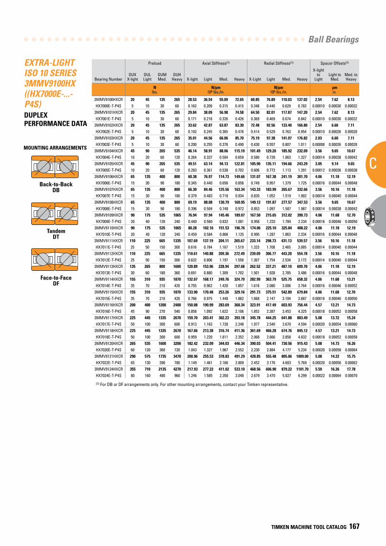
Ball Bearings
C
TIMKEN MACHINE TOOL CATALOG 167
EXTRA-LIGHT ISO 10 SERIES 3MMV9100HX ((HX7000E-...-P4S)DUPLEX PERFORMANCE DATA
Preload Axial Stiffness(1) Radial Stiffness(1) Spacer Offsets(1)
Bearing NumberDUX
X-lightDULLight
DUMMed.
DUHHeavy X-light Light Med. Heavy X-Light Light Med. Heavy
X-light to
LightLight toMed.
Med. toHeavy
N lbs.
N/µm 106 lbs./in.
N/µm 106 lbs./in.
µm in.
3MMV9100HXCR 20 45 135 265 28.53 36.54 55.09 72.65 60.85 76.89 110.03 137.02 2.54 7.62 8.13HX7000E-T-P4S 5 10 30 60 0.163 0.209 0.315 0.415 0.348 0.440 0.629 0.783 0.00010 0.00030 0.00032
3MMV9101HXCR 20 45 135 265 29.84 38.09 56.98 74.58 64.50 82.01 117.87 147.20 2.54 7.62 8.13HX7001E-T-P4S 5 10 30 60 0.171 0.218 0.326 0.426 0.369 0.469 0.674 0.842 0.00010 0.00030 0.00032
3MMV9102HXCR 20 45 135 265 33.62 42.87 63.87 83.30 72.48 92.56 133.40 166.80 2.54 6.60 7.11HX7002E-T-P4S 5 10 30 60 0.192 0.245 0.365 0.476 0.414 0.529 0.763 0.954 0.00010 0.00026 0.00028
3MMV9103HXCR 20 45 135 265 35.01 44.56 66.06 85.70 75.19 97.38 141.07 176.82 2.03 6.60 7.11HX7003E-T-P4S 5 10 30 60 0.200 0.255 0.378 0.490 0.430 0.557 0.807 1.011 0.00008 0.00026 0.00028
3MMV9104HXCR 45 90 265 535 46.14 58.91 88.06 115.19 101.49 129.20 185.92 232.09 3.56 9.65 10.67HX7004E-T-P4S 10 20 60 120 0.264 0.337 0.504 0.659 0.580 0.739 1.063 1.327 0.00014 0.00038 0.00042
3MMV9105HXCR 45 90 265 535 49.51 63.14 94.13 122.81 105.90 135.11 194.66 243.29 3.05 9.14 9.65HX7005E-T-P4S 10 20 60 120 0.283 0.361 0.538 0.702 0.606 0.773 1.113 1.391 0.00012 0.00036 0.00038
3MMV9106HXCR 65 135 400 800 60.38 76.97 114.73 149.66 131.07 167.38 241.19 301.70 4.06 11.18 12.19HX7006E-T-P4S 15 30 90 180 0.345 0.440 0.656 0.856 0.749 0.957 1.379 1.725 0.00016 0.00044 0.00048
3MMV9107HXCR 65 135 400 800 66.30 84.46 125.56 163.34 143.33 183.99 265.67 332.66 3.56 10.16 11.18HX7007E-T-P4S 15 30 90 180 0.379 0.483 0.718 0.934 0.820 1.052 1.519 1.902 0.00014 0.00040 0.00044
3MMV9108HXCR 65 135 400 800 69.19 88.08 130.79 169.95 149.12 191.87 277.57 347.53 3.56 9.65 10.67HX7008E-T-P4S 15 30 90 180 0.396 0.504 0.748 0.972 0.853 1.097 1.587 1.987 0.00014 0.00038 0.00042
3MMV9109HXCR 90 175 535 1065 76.94 97.94 145.46 189.07 167.50 215.65 312.02 390.73 4.06 11.68 12.70HX7009E-T-P4S 20 40 120 240 0.440 0.560 0.832 1.081 0.958 1.233 1.784 2.234 0.00016 0.00046 0.00050
3MMV9110HXCR 90 175 535 1065 80.28 102.16 151.53 196.76 174.06 225.10 325.84 408.22 4.06 11.18 12.19HX7010E-T-P4S 20 40 120 240 0.459 0.584 0.866 1.125 0.995 1.287 1.863 2.334 0.00016 0.00044 0.00048
3MMV9111HXCR 110 225 665 1335 107.69 137.19 204.11 265.67 233.14 298.73 431.13 539.57 3.56 10.16 11.18HX7011E-T-P4S 25 50 150 300 0.616 0.784 1.167 1.519 1.333 1.708 2.465 3.085 0.00014 0.00040 0.00044
3MMV9112HXCR 110 225 665 1335 110.61 140.88 209.36 272.49 239.09 306.77 443.20 554.78 3.56 10.16 11.18HX7012E-T-P4S 25 50 150 300 0.632 0.806 1.197 1.558 1.367 1.754 2.534 3.172 0.00014 0.00040 0.00044
3MMV9113HXCR 135 265 800 1600 120.89 153.96 228.94 297.68 262.52 337.21 487.10 609.70 4.06 11.18 12.19HX7013E-T-P4S 30 60 180 360 0.691 0.880 1.309 1.702 1.501 1.928 2.785 3.486 0.00016 0.00044 0.00048
3MMV9114HXCR 155 310 935 1870 132.07 168.17 249.76 324.79 282.99 363.79 525.75 658.32 4.06 11.68 13.21HX7014E-T-P4S 35 70 210 420 0.755 0.962 1.428 1.857 1.618 2.080 3.006 3.764 0.00016 0.00046 0.00052
3MMV9115HXCR 155 310 935 1870 133.90 170.48 253.26 329.16 291.73 375.51 542.89 679.84 4.06 11.68 12.70HX7015E-T-P4S 35 70 210 420 0.766 0.975 1.448 1.882 1.668 2.147 3.104 3.887 0.00016 0.00046 0.00050
3MMV9116HXCR 200 400 1200 2400 150.08 190.99 283.69 368.34 323.91 417.49 603.93 756.44 4.57 13.21 14.73HX7016E-T-P4S 45 90 270 540 0.858 1.092 1.622 2.106 1.852 2.387 3.453 4.325 0.00018 0.00052 0.00058
3MMV9117HXCR 225 445 1335 2670 159.70 203.41 302.23 393.18 345.78 444.25 641.88 803.49 5.08 13.72 15.24HX7017E-T-P4S 50 100 300 600 0.913 1.163 1.728 2.248 1.977 2.540 3.670 4.594 0.00020 0.00054 0.00060
3MMV9118HXCR 225 445 1335 2670 167.66 213.38 316.74 411.36 361.69 466.28 674.76 845.12 4.57 13.21 14.73HX7018E-T-P4S 50 100 300 600 0.959 1.220 1.811 2.352 2.068 2.666 3.858 4.832 0.00018 0.00052 0.00058
3MMV9120HXCR 265 535 1600 3200 182.42 232.09 344.03 446.34 390.03 504.41 730.56 915.43 5.08 14.73 16.26HX7020E-T-P4S 60 120 360 720 1.043 1.327 1.967 2.552 2.230 2.884 4.177 5.234 0.00020 0.00058 0.00064
3MMV9121HXCR 290 575 1735 3470 200.96 255.53 378.83 491.29 428.85 555.48 805.06 1009.00 5.08 14.22 15.75HX7022E-T-P4S 65 130 390 780 1.149 1.461 2.166 2.809 2.452 3.176 4.603 5.769 0.00020 0.00056 0.00062
3MMV9124HXCR 355 710 2135 4270 217.93 277.22 411.02 533.10 468.56 606.90 879.22 1101.70 5.59 16.26 17.78HX7024E-T-P4S 80 160 480 960 1.246 1.585 2.350 3.048 2.679 3.470 5.027 6.299 0.00022 0.00064 0.00070
(1) For DB or DF arrangements only. For other mounting arrangements, contact your Timken representative.
MOUNTING ARRANGEMENTS
Back-to-BackDB
TandemDT
Face-to-FaceDF
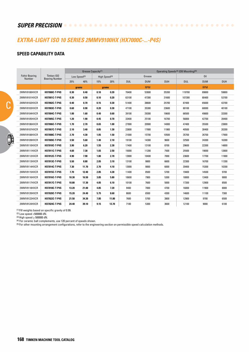
SUPER PRECISION
C
168 TIMKEN MACHINE TOOL CATALOG
EXTRA-LIGHT ISO 10 SERIES 2MMV9100HX (HX7000C-...-P4S)
SPEED CAPABILITY DATA
Fafnir Bearing Number
Timken ISO Bearing Number
Grease Capacity(1) Operating Speeds(4) (DB Mounting)(5)
Low Speed(2) High Speed(3) Grease Oil
25% 40% 15% 20% DUL DUM DUH DUL DUM DUH
grams grams RPM RPM
2MMV9100HXCR HX7000C-T-P4S 0.30 0.40 0.10 0.20 70400 52800 35200 119700 89800 59800
2MMV9101HXCR HX7001C-T-P4S 0.30 0.50 0.10 0.20 63100 47300 31600 107300 80400 53700
2MMV9102HXCR HX7002C-T-P4S 0.40 0.70 0.15 0.30 51400 38600 25700 87400 65600 43700
2MMV9103HXCR HX7003C-T-P4S 0.60 0.90 0.20 0.30 47100 35300 23600 80100 60000 40100
2MMV9104HXCR HX7004C-T-P4S 1.00 1.60 0.40 0.60 39100 29300 19600 66500 49800 33300
2MMV9105HXCR HX7005C-T-P4S 1.20 1.90 0.45 0.70 33400 25100 16700 56800 42700 28400
2MMV9106HXCR HX7006C-T-P4S 1.70 2.70 0.65 1.00 27900 20900 14000 47400 35500 23800
2MMV9107HXCR HX7007C-T-P4S 2.10 3.40 0.85 1.30 23800 17900 11900 40500 30400 20200
2MMV9108HXCR HX7008C-T-P4S 2.70 4.30 1.05 1.50 21000 15700 10500 35700 26700 17900
2MMV9109HXCR HX7009C-T-P4S 3.50 5.60 1.40 2.10 19100 14300 9600 32500 24300 16300
2MMV9110HXCR HX7010C-T-P4S 3.90 6.20 1.55 2.30 17400 13100 8700 29600 22300 14800
2MMV9111HXCR HX7011C-T-P4S 4.60 7.30 1.65 2.50 15000 11200 7500 25500 19000 12800
2MMV9112HXCR HX7012C-T-P4S 4.90 7.90 1.80 2.70 13900 10400 7000 23600 17700 11900
2MMV9113HXCR HX7013C-T-P4S 5.50 8.80 2.05 3.10 13100 9800 6600 22300 16700 11200
2MMV9114HXCR HX7014C-T-P4S 7.30 11.70 2.70 4.10 12000 9000 6000 20400 15300 10200
2MMV9115HXCR HX7015C-T-P4S 7.70 12.40 2.85 4.30 11400 8500 5700 19400 14500 9700
2MMV9116HXCR HX7016C-T-P4S 10.30 16.50 3.85 5.80 10600 7900 5300 18000 13400 9000
2MMV9117HXCR HX7017C-T-P4S 10.80 17.30 4.05 6.10 10100 7600 5000 17200 12900 8500
2MMV9118HXCR HX7018C-T-P4S 13.20 21.00 4.85 7.20 9400 7000 4700 16000 11900 8000
2MMV9120HXCR HX7020C-T-P4S 15.20 24.40 5.75 8.60 8600 6500 4300 14600 11100 7300
2MMV9122HXCR HX7022C-T-P4S 21.50 34.30 7.85 11.80 7600 5700 3800 12900 9700 6500
2MMV9124HXCR HX7024C-T-P4S 24.40 39.10 9.15 13.70 7100 5300 3600 12100 9000 6100
(1) Fill weights based on specific gravity of 0.99.(2) Low speed <500000 dN.(3) High speed > 500000 dN.(4) For ceramic ball complements, use 120 percent of speeds shown.(5) For other mounting arrangement configurations, refer to the engineering section on permissible speed calculation methods.
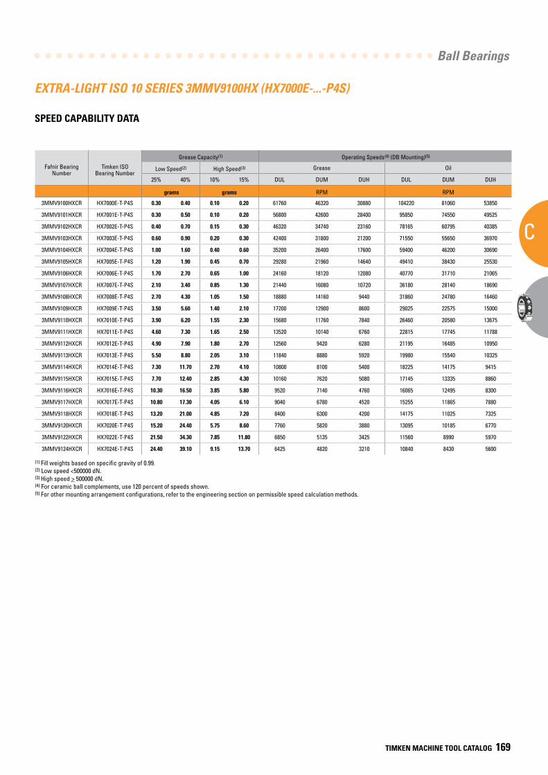
Ball Bearings
C
TIMKEN MACHINE TOOL CATALOG 169
EXTRA-LIGHT ISO 10 SERIES 3MMV9100HX (HX7000E-...-P4S)
SPEED CAPABILITY DATA
Fafnir Bearing Number
Timken ISO Bearing Number
Grease Capacity(1) Operating Speeds(4) (DB Mounting)(5)
Low Speed(2) High Speed(3) Grease Oil
25% 40% 10% 15% DUL DUM DUH DUL DUM DUH
grams grams RPM RPM
3MMV9100HXCR HX7000E-T-P4S 0.30 0.40 0.10 0.20 61760 46320 30880 104220 81060 53850
3MMV9101HXCR HX7001E-T-P4S 0.30 0.50 0.10 0.20 56800 42600 28400 95850 74550 49525
3MMV9102HXCR HX7002E-T-P4S 0.40 0.70 0.15 0.30 46320 34740 23160 78165 60795 40385
3MMV9103HXCR HX7003E-T-P4S 0.60 0.90 0.20 0.30 42400 31800 21200 71550 55650 36970
3MMV9104HXCR HX7004E-T-P4S 1.00 1.60 0.40 0.60 35200 26400 17600 59400 46200 30690
3MMV9105HXCR HX7005E-T-P4S 1.20 1.90 0.45 0.70 29280 21960 14640 49410 38430 25530
3MMV9106HXCR HX7006E-T-P4S 1.70 2.70 0.65 1.00 24160 18120 12080 40770 31710 21065
3MMV9107HXCR HX7007E-T-P4S 2.10 3.40 0.85 1.30 21440 16080 10720 36180 28140 18690
3MMV9108HXCR HX7008E-T-P4S 2.70 4.30 1.05 1.50 18880 14160 9440 31860 24780 16460
3MMV9109HXCR HX7009E-T-P4S 3.50 5.60 1.40 2.10 17200 12900 8600 29025 22575 15000
3MMV9110HXCR HX7010E-T-P4S 3.90 6.20 1.55 2.30 15680 11760 7840 26460 20580 13675
3MMV9111HXCR HX7011E-T-P4S 4.60 7.30 1.65 2.50 13520 10140 6760 22815 17745 11788
3MMV9112HXCR HX7012E-T-P4S 4.90 7.90 1.80 2.70 12560 9420 6280 21195 16485 10950
3MMV9113HXCR HX7013E-T-P4S 5.50 8.80 2.05 3.10 11840 8880 5920 19980 15540 10325
3MMV9114HXCR HX7014E-T-P4S 7.30 11.70 2.70 4.10 10800 8100 5400 18225 14175 9415
3MMV9115HXCR HX7015E-T-P4S 7.70 12.40 2.85 4.30 10160 7620 5080 17145 13335 8860
3MMV9116HXCR HX7016E-T-P4S 10.30 16.50 3.85 5.80 9520 7140 4760 16065 12495 8300
3MMV9117HXCR HX7017E-T-P4S 10.80 17.30 4.05 6.10 9040 6780 4520 15255 11865 7880
3MMV9118HXCR HX7018E-T-P4S 13.20 21.00 4.85 7.20 8400 6300 4200 14175 11025 7325
3MMV9120HXCR HX7020E-T-P4S 15.20 24.40 5.75 8.60 7760 5820 3880 13095 10185 6770
3MMV9122HXCR HX7022E-T-P4S 21.50 34.30 7.85 11.80 6850 5135 3425 11560 8990 5970
3MMV9124HXCR HX7024E-T-P4S 24.40 39.10 9.15 13.70 6425 4820 3210 10840 8430 5600
(1) Fill weights based on specific gravity of 0.99.(2) Low speed <500000 dN.(3) High speed > 500000 dN.(4) For ceramic ball complements, use 120 percent of speeds shown.(5) For other mounting arrangement configurations, refer to the engineering section on permissible speed calculation methods.
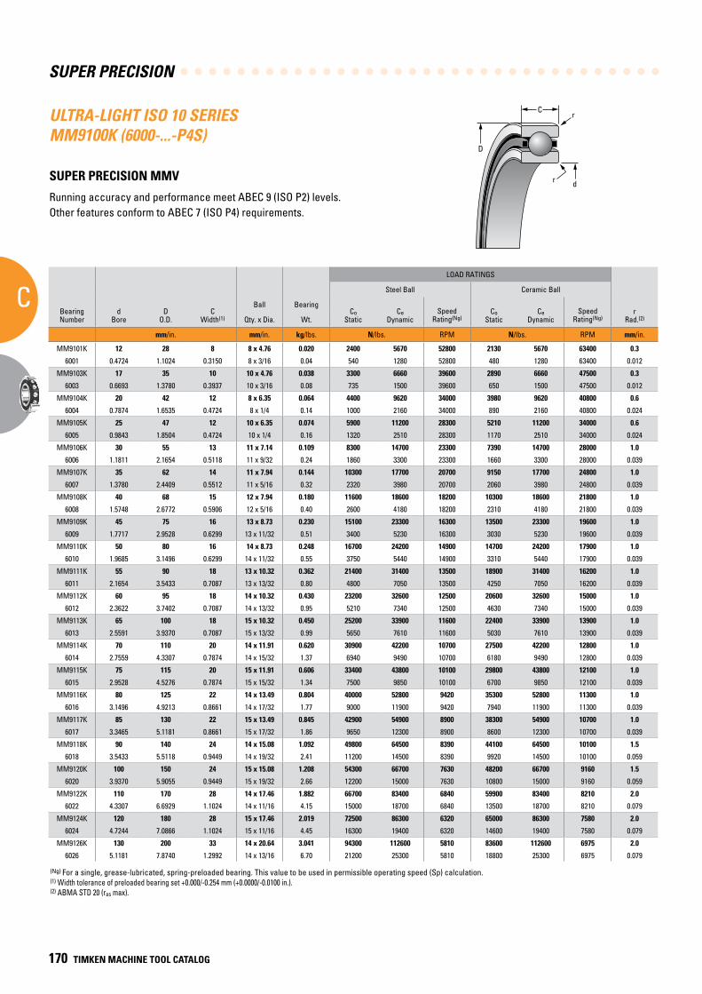
SUPER PRECISION
C
170 TIMKEN MACHINE TOOL CATALOG
(Ng) For a single, grease-lubricated, spring-preloaded bearing. This value to be used in permissible operating speed (Sp) calculation.(1) Width tolerance of preloaded bearing set +0.000/-0.254 mm (+0.0000/-0.0100 in.).(2) ABMA STD 20 (ras max).
ULTRA-LIGHT ISO 10 SERIES MM9100K (6000-...-P4S)
SUPER PRECISION MMV
Running accuracy and performance meet ABEC 9 (ISO P2) levels. Other features conform to ABEC 7 (ISO P4) requirements.
BearingNumber
dBore
DO.D.
CWidth(1)
Ball Bearing
LOAD RATINGS
rRad.(2)
Suggested Shoulder Diameters Shaft Diameter Mounting Fits
FIXED FLOATING
Steel Ball Ceramic Ball Housing Bore (Stationary) Mounting Fits Housing Bore
(Stationary) Mounting Fits
CoStatic
CeDynamic
SpeedRating(Ng)
CoStatic
CeDynamic
SpeedRating(Ng)
Shaft Housing
Qty. x Dia. Wt. Max. Min. Max. Min. Max. Min. Loose Tight Max. Min. Tight Loose Max. Min. Loose Loose
mm/in. mm/in. kg/lbs. N/lbs. RPM N/lbs. RPM mm/in. mm/in. mm/in. mm/in. mm/in. mm/in. mm/in. mm/in. mm/in.
MM9101K 12 28 8 8 x 4.76 0.020 2400 5670 52800 2130 5670 63400 0.3 16.1 15.9 25.5 25.3 12.000 11.995 0.005 0.004 28.005 28.000 0.000 0.010 28.010 28.005 0.015 0.005
6001 0.4724 1.1024 0.3150 8 x 3/16 0.04 540 1280 52800 480 1280 63400 0.012 0.64 0.63 1.01 1.00 0.47240 0.47220 0.00020 0.00015 1.10260 1.10240 0.00000 0.00040 1.10280 1.10260 0.00060 0.00020
MM9103K 17 35 10 10 x 4.76 0.038 3300 6660 39600 2890 6660 47500 0.3 21.7 21.5 31.1 30.9 17.000 16.995 0.005 0.004 35.006 35.000 0.000 0.012 35.010 35.005 0.016 0.005
6003 0.6693 1.3780 0.3937 10 x 3/16 0.08 735 1500 39600 650 1500 47500 0.012 0.86 0.85 1.23 1.22 0.66930 0.66910 0.00020 0.00015 1.37830 1.37800 0.00000 0.00050 1.37840 1.37820 0.00070 0.00020
MM9104K 20 42 12 8 x 6.35 0.064 4400 9620 34000 3980 9620 40800 0.6 25.0 24.8 37.7 37.5 20.000 19.995 0.005 0.005 42.006 42.000 0.000 0.012 42.010 42.005 0.016 0.005
6004 0.7874 1.6535 0.4724 8 x 1/4 0.14 1000 2160 34000 890 2160 40800 0.024 0.99 0.98 1.49 1.48 0.78740 0.78720 0.00020 0.00020 1.65380 1.65350 0.00000 0.00050 1.65390 1.65370 0.00070 0.00020
MM9105K 25 47 12 10 x 6.35 0.074 5900 11200 28300 5210 11200 34000 0.6 30.1 29.9 42.6 42.3 25.000 24.995 0.005 0.005 47.006 47.000 0.000 0.012 47.012 47.007 0.018 0.007
6005 0.9843 1.8504 0.4724 10 x 1/4 0.16 1320 2510 28300 1170 2510 34000 0.024 1.19 1.18 1.68 1.67 0.98430 0.98410 0.00020 0.00020 1.85070 1.85040 0.00000 0.00050 1.85090 1.85070 0.00080 0.00030
MM9106K 30 55 13 11 x 7.14 0.109 8300 14700 23300 7390 14700 28000 1.0 36.2 35.9 50.7 50.4 30.000 29.995 0.005 0.005 55.008 55.000 0.000 0.015 55.012 55.007 0.019 0.007
6006 1.1811 2.1654 0.5118 11 x 9/32 0.24 1860 3300 23300 1660 3300 28000 0.039 1.43 1.42 2.00 1.99 1.18110 1.18090 0.00020 0.00020 2.16570 2.16540 0.00000 0.00060 2.16590 2.16570 0.00080 0.00030
MM9107K 35 62 14 11 x 7.94 0.144 10300 17700 20700 9150 17700 24800 1.0 41.2 40.6 56.6 56.1 35.000 34.995 0.005 0.006 62.008 62.000 0.000 0.015 62.012 62.007 0.019 0.007
6007 1.3780 2.4409 0.5512 11 x 5/16 0.32 2320 3980 20700 2060 3980 24800 0.039 1.62 1.60 2.23 2.21 1.37800 1.37780 0.00020 0.00025 2.44120 2.44090 0.00000 0.00060 2.44140 2.44120 0.00080 0.00030
MM9108K 40 68 15 12 x 7.94 0.180 11600 18600 18200 10300 18600 21800 1.0 46.2 45.7 62.2 61.7 40.000 39.995 0.005 0.006 68.008 68.000 0.000 0.015 68.012 68.007 0.019 0.007
6008 1.5748 2.6772 0.5906 12 x 5/16 0.40 2600 4180 18200 2310 4180 21800 0.039 1.82 1.80 2.45 2.43 1.57480 1.57460 0.00020 0.00025 2.67750 2.67720 0.00000 0.00060 2.67770 2.67750 0.00080 0.00030
MM9109K 45 75 16 13 x 8.73 0.230 15100 23300 16300 13500 23300 19600 1.0 51.8 51.3 69.3 68.8 45.000 44.995 0.005 0.006 75.008 75.000 0.000 0.015 75.014 75.009 0.022 0.009
6009 1.7717 2.9528 0.6299 13 x 11/32 0.51 3400 5230 16300 3030 5230 19600 0.039 2.04 2.02 2.73 2.71 1.77170 1.77150 0.00020 0.00025 2.95310 2.95280 0.00000 0.00060 2.95330 2.95310 0.00080 0.00030
MM9110K 50 80 16 14 x 8.73 0.248 16700 24200 14900 14700 24200 17900 1.0 56.6 56.1 74.2 73.7 50.000 49.995 0.005 0.006 80.008 80.000 0.000 0.015 80.012 80.008 0.020 0.008
6010 1.9685 3.1496 0.6299 14 x 11/32 0.55 3750 5440 14900 3310 5440 17900 0.039 2.23 2.21 2.92 2.90 1.96850 1.96830 0.00020 0.00025 3.14990 3.14960 0.00000 0.00060 3.15010 3.14990 0.00080 0.00030
MM9111K 55 90 18 13 x 10.32 0.362 21400 31400 13500 18900 31400 16200 1.0 62.7 62.2 83.3 82.8 55.000 54.995 0.005 0.007 90.008 90.000 0.000 0.016 90.015 90.007 0.023 0.007
6011 2.1654 3.5433 0.7087 13 x 13/32 0.80 4800 7050 13500 4250 7050 16200 0.039 2.47 2.45 3.28 3.26 2.16540 2.16520 0.00020 0.00030 3.54360 3.54330 0.00000 0.00060 3.54390 3.54360 0.00090 0.00030
MM9112K 60 95 18 14 x 10.32 0.430 23200 32600 12500 20600 32600 15000 1.0 67.8 67.3 88.1 87.6 60.000 59.995 0.005 0.007 95.008 95.000 0.000 0.016 95.016 95.009 0.024 0.009
6012 2.3622 3.7402 0.7087 14 x 13/32 0.95 5210 7340 12500 4630 7340 15000 0.039 2.67 2.65 3.47 3.45 2.36220 2.36200 0.00020 0.00030 3.74050 3.74020 0.00000 0.00060 3.74080 3.74050 0.00090 0.00030
MM9113K 65 100 18 15 x 10.32 0.450 25200 33900 11600 22400 33900 13900 1.0 72.6 72.1 93.2 92.7 65.000 64.995 0.005 0.007 100.008 100.000 0.000 0.016 100.018 100.010 0.025 0.010
6013 2.5591 3.9370 0.7087 15 x 13/32 0.99 5650 7610 11600 5030 7610 13900 0.039 2.86 2.84 3.67 3.65 2.55910 2.55890 0.00020 0.00030 3.93730 3.93700 0.00000 0.00060 3.93770 3.93740 0.00100 0.00040
MM9114K 70 110 20 14 x 11.91 0.620 30900 42200 10700 27500 42200 12800 1.0 78.2 77.7 102.4 101.9 70.000 69.995 0.005 0.007 110.008 110.000 0.000 0.016 110.018 110.010 0.025 0.010
6014 2.7559 4.3307 0.7874 14 x 15/32 1.37 6940 9490 10700 6180 9490 12800 0.039 3.08 3.06 4.03 4.01 2.75590 2.75570 0.00020 0.00030 4.33100 4.33070 0.00000 0.00060 4.33140 4.33110 0.00100 0.00040
MM9115K 75 115 20 15 x 11.91 0.606 33400 43800 10100 29800 43800 12100 1.0 83.4 82.7 107.3 106.6 75.005 74.995 0.005 0.012 115.008 115.000 0.000 0.016 115.019 115.011 0.026 0.010
6015 2.9528 4.5276 0.7874 15 x 15/32 1.34 7500 9850 10100 6700 9850 12100 0.039 3.29 3.26 4.23 4.20 2.95300 2.95260 0.00020 0.00050 4.52790 4.52760 0.00000 0.00060 4.52830 4.52800 0.00100 0.00040
MM9116K 80 125 22 14 x 13.49 0.804 40000 52800 9420 35300 52800 11300 1.0 89.3 88.5 116.5 115.7 80.005 79.995 0.005 0.012 125.008 125.000 0.000 0.017 125.021 125.011 0.030 0.011
6016 3.1496 4.9213 0.8661 14 x 17/32 1.77 9000 11900 9420 7940 11900 11300 0.039 3.52 3.49 4.59 4.56 3.14980 3.14940 0.00020 0.00050 4.92160 4.92130 0.00000 0.00070 4.92210 4.92170 0.00120 0.00040
MM9117K 85 130 22 15 x 13.49 0.845 42900 54900 8900 38300 54900 10700 1.0 94.9 94.1 122.1 121.3 85.005 84.995 0.005 0.012 130.009 130.000 0.000 0.018 130.020 130.010 0.029 0.010
6017 3.3465 5.1181 0.8661 15 x 17/32 1.86 9650 12300 8900 8600 12300 10700 0.039 3.74 3.71 4.81 4.78 3.34670 3.34630 0.00020 0.00050 5.11850 5.11810 0.00000 0.00070 5.11890 5.11850 0.00110 0.00040
MM9118K 90 140 24 14 x 15.08 1.092 49800 64500 8390 44100 64500 10100 1.5 100.5 99.7 130.9 130.2 90.005 89.995 0.005 0.013 140.009 140.000 0.000 0.018 140.020 140.010 0.029 0.010
6018 3.5433 5.5118 0.9449 14 x 19/32 2.41 11200 14500 8390 9920 14500 10100 0.059 3.96 3.93 5.16 5.13 3.54350 3.54310 0.00020 0.00050 5.51220 5.51180 0.00000 0.00070 5.51260 5.51220 0.00110 0.00040
MM9120K 100 150 24 15 x 15.08 1.208 54300 66700 7630 48200 66700 9160 1.5 110.6 109.9 140.8 140.1 100.005 99.995 0.005 0.013 150.009 150.000 0.000 0.018 150.023 150.012 0.032 0.012
6020 3.9370 5.9055 0.9449 15 x 19/32 2.66 12200 15000 7630 10800 15000 9160 0.059 4.36 4.33 5.55 5.52 3.93720 3.93680 0.00020 0.00050 5.90590 5.90550 0.00000 0.00070 5.90640 5.90600 0.00120 0.00050
MM9122K 110 170 28 14 x 17.46 1.882 66700 83400 6840 59900 83400 8210 2.0 123.1 122.3 158.4 157.6 110.005 109.995 0.005 0.013 170.010 170.000 0.000 0.020 170.022 170.012 0.032 0.012
6022 4.3307 6.6929 1.1024 14 x 11/16 4.15 15000 18700 6840 13500 18700 8210 0.079 4.85 4.82 6.24 6.21 4.33090 4.33050 0.00020 0.00050 6.69330 6.69290 0.00000 0.00080 6.69380 6.69340 0.00130 0.00050
MM9124K 120 180 28 15 x 17.46 2.019 72500 86300 6320 65000 86300 7580 2.0 133.2 132.5 168.3 167.5 120.005 119.995 0.005 0.013 180.010 180.000 0.000 0.020 180.022 180.012 0.032 0.012
6024 4.7244 7.0866 1.1024 15 x 11/16 4.45 16300 19400 6320 14600 19400 7580 0.079 5.25 5.22 6.63 6.60 4.72460 4.72420 0.00020 0.00050 7.08700 7.08660 0.00000 0.00080 7.08750 7.08710 0.00130 0.00050
MM9126K 130 200 33 14 x 20.64 3.041 94300 112600 5810 83600 112600 6975 2.0 144.9 144.2 186.6 185.8 130.005 129.995 0.005 0.015 200.011 200.000 0.000 0.022 200.025 200.015 0.036 0.015
6026 5.1181 7.8740 1.2992 14 x 13/16 6.70 21200 25300 5810 18800 25300 6975 0.079 5.71 5.68 7.35 7.32 5.11830 5.11790 0.00020 0.00060 7.87450 7.87400 0.00000 0.00090 7.87500 7.87460 0.00150 0.00060
C
D
r
dr
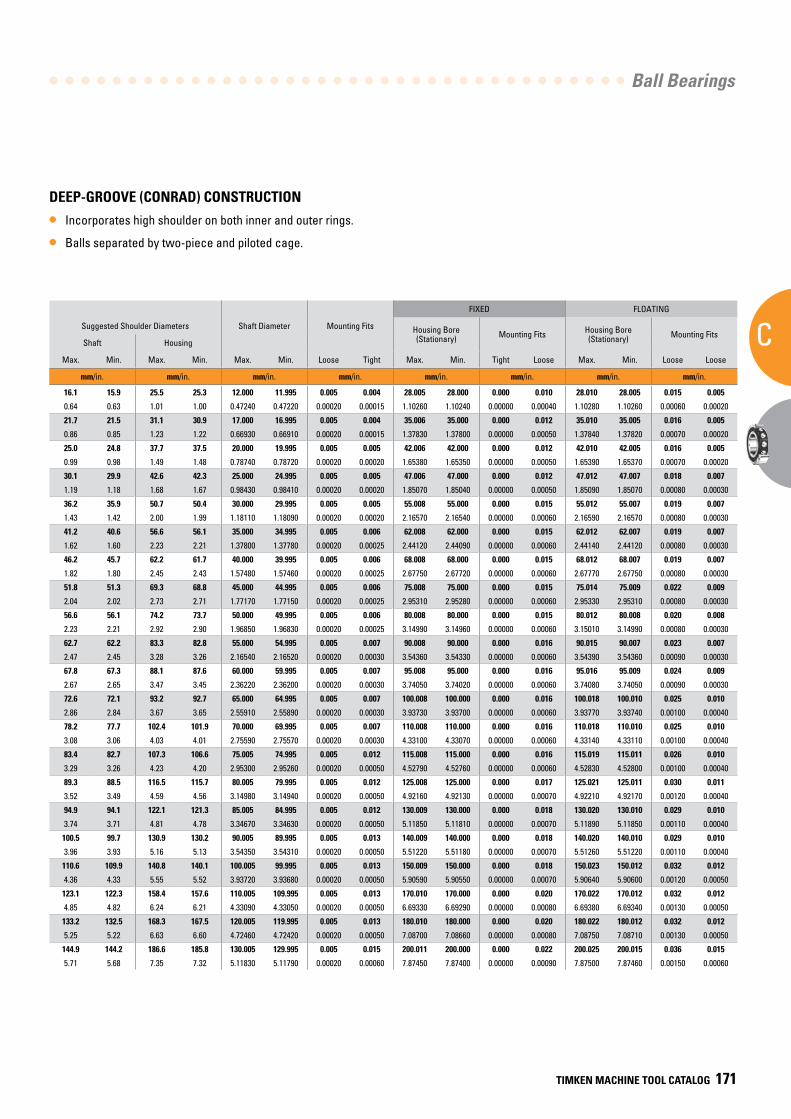
Ball Bearings
C
TIMKEN MACHINE TOOL CATALOG 171
DEEP-GROOVE (CONRAD) CONSTRUCTION
• Incorporates high shoulder on both inner and outer rings.
• Balls separated by two-piece and piloted cage.
BearingNumber
dBore
DO.D.
CWidth(1)
Ball Bearing
LOAD RATINGS
rRad.(2)
Suggested Shoulder Diameters Shaft Diameter Mounting Fits
FIXED FLOATING
Steel Ball Ceramic Ball Housing Bore (Stationary) Mounting Fits Housing Bore
(Stationary) Mounting Fits
CoStatic
CeDynamic
SpeedRating(Ng)
CoStatic
CeDynamic
SpeedRating(Ng)
Shaft Housing
Qty. x Dia. Wt. Max. Min. Max. Min. Max. Min. Loose Tight Max. Min. Tight Loose Max. Min. Loose Loose
mm/in. mm/in. kg/lbs. N/lbs. RPM N/lbs. RPM mm/in. mm/in. mm/in. mm/in. mm/in. mm/in. mm/in. mm/in. mm/in.
MM9101K 12 28 8 8 x 4.76 0.020 2400 5670 52800 2130 5670 63400 0.3 16.1 15.9 25.5 25.3 12.000 11.995 0.005 0.004 28.005 28.000 0.000 0.010 28.010 28.005 0.015 0.005
6001 0.4724 1.1024 0.3150 8 x 3/16 0.04 540 1280 52800 480 1280 63400 0.012 0.64 0.63 1.01 1.00 0.47240 0.47220 0.00020 0.00015 1.10260 1.10240 0.00000 0.00040 1.10280 1.10260 0.00060 0.00020
MM9103K 17 35 10 10 x 4.76 0.038 3300 6660 39600 2890 6660 47500 0.3 21.7 21.5 31.1 30.9 17.000 16.995 0.005 0.004 35.006 35.000 0.000 0.012 35.010 35.005 0.016 0.005
6003 0.6693 1.3780 0.3937 10 x 3/16 0.08 735 1500 39600 650 1500 47500 0.012 0.86 0.85 1.23 1.22 0.66930 0.66910 0.00020 0.00015 1.37830 1.37800 0.00000 0.00050 1.37840 1.37820 0.00070 0.00020
MM9104K 20 42 12 8 x 6.35 0.064 4400 9620 34000 3980 9620 40800 0.6 25.0 24.8 37.7 37.5 20.000 19.995 0.005 0.005 42.006 42.000 0.000 0.012 42.010 42.005 0.016 0.005
6004 0.7874 1.6535 0.4724 8 x 1/4 0.14 1000 2160 34000 890 2160 40800 0.024 0.99 0.98 1.49 1.48 0.78740 0.78720 0.00020 0.00020 1.65380 1.65350 0.00000 0.00050 1.65390 1.65370 0.00070 0.00020
MM9105K 25 47 12 10 x 6.35 0.074 5900 11200 28300 5210 11200 34000 0.6 30.1 29.9 42.6 42.3 25.000 24.995 0.005 0.005 47.006 47.000 0.000 0.012 47.012 47.007 0.018 0.007
6005 0.9843 1.8504 0.4724 10 x 1/4 0.16 1320 2510 28300 1170 2510 34000 0.024 1.19 1.18 1.68 1.67 0.98430 0.98410 0.00020 0.00020 1.85070 1.85040 0.00000 0.00050 1.85090 1.85070 0.00080 0.00030
MM9106K 30 55 13 11 x 7.14 0.109 8300 14700 23300 7390 14700 28000 1.0 36.2 35.9 50.7 50.4 30.000 29.995 0.005 0.005 55.008 55.000 0.000 0.015 55.012 55.007 0.019 0.007
6006 1.1811 2.1654 0.5118 11 x 9/32 0.24 1860 3300 23300 1660 3300 28000 0.039 1.43 1.42 2.00 1.99 1.18110 1.18090 0.00020 0.00020 2.16570 2.16540 0.00000 0.00060 2.16590 2.16570 0.00080 0.00030
MM9107K 35 62 14 11 x 7.94 0.144 10300 17700 20700 9150 17700 24800 1.0 41.2 40.6 56.6 56.1 35.000 34.995 0.005 0.006 62.008 62.000 0.000 0.015 62.012 62.007 0.019 0.007
6007 1.3780 2.4409 0.5512 11 x 5/16 0.32 2320 3980 20700 2060 3980 24800 0.039 1.62 1.60 2.23 2.21 1.37800 1.37780 0.00020 0.00025 2.44120 2.44090 0.00000 0.00060 2.44140 2.44120 0.00080 0.00030
MM9108K 40 68 15 12 x 7.94 0.180 11600 18600 18200 10300 18600 21800 1.0 46.2 45.7 62.2 61.7 40.000 39.995 0.005 0.006 68.008 68.000 0.000 0.015 68.012 68.007 0.019 0.007
6008 1.5748 2.6772 0.5906 12 x 5/16 0.40 2600 4180 18200 2310 4180 21800 0.039 1.82 1.80 2.45 2.43 1.57480 1.57460 0.00020 0.00025 2.67750 2.67720 0.00000 0.00060 2.67770 2.67750 0.00080 0.00030
MM9109K 45 75 16 13 x 8.73 0.230 15100 23300 16300 13500 23300 19600 1.0 51.8 51.3 69.3 68.8 45.000 44.995 0.005 0.006 75.008 75.000 0.000 0.015 75.014 75.009 0.022 0.009
6009 1.7717 2.9528 0.6299 13 x 11/32 0.51 3400 5230 16300 3030 5230 19600 0.039 2.04 2.02 2.73 2.71 1.77170 1.77150 0.00020 0.00025 2.95310 2.95280 0.00000 0.00060 2.95330 2.95310 0.00080 0.00030
MM9110K 50 80 16 14 x 8.73 0.248 16700 24200 14900 14700 24200 17900 1.0 56.6 56.1 74.2 73.7 50.000 49.995 0.005 0.006 80.008 80.000 0.000 0.015 80.012 80.008 0.020 0.008
6010 1.9685 3.1496 0.6299 14 x 11/32 0.55 3750 5440 14900 3310 5440 17900 0.039 2.23 2.21 2.92 2.90 1.96850 1.96830 0.00020 0.00025 3.14990 3.14960 0.00000 0.00060 3.15010 3.14990 0.00080 0.00030
MM9111K 55 90 18 13 x 10.32 0.362 21400 31400 13500 18900 31400 16200 1.0 62.7 62.2 83.3 82.8 55.000 54.995 0.005 0.007 90.008 90.000 0.000 0.016 90.015 90.007 0.023 0.007
6011 2.1654 3.5433 0.7087 13 x 13/32 0.80 4800 7050 13500 4250 7050 16200 0.039 2.47 2.45 3.28 3.26 2.16540 2.16520 0.00020 0.00030 3.54360 3.54330 0.00000 0.00060 3.54390 3.54360 0.00090 0.00030
MM9112K 60 95 18 14 x 10.32 0.430 23200 32600 12500 20600 32600 15000 1.0 67.8 67.3 88.1 87.6 60.000 59.995 0.005 0.007 95.008 95.000 0.000 0.016 95.016 95.009 0.024 0.009
6012 2.3622 3.7402 0.7087 14 x 13/32 0.95 5210 7340 12500 4630 7340 15000 0.039 2.67 2.65 3.47 3.45 2.36220 2.36200 0.00020 0.00030 3.74050 3.74020 0.00000 0.00060 3.74080 3.74050 0.00090 0.00030
MM9113K 65 100 18 15 x 10.32 0.450 25200 33900 11600 22400 33900 13900 1.0 72.6 72.1 93.2 92.7 65.000 64.995 0.005 0.007 100.008 100.000 0.000 0.016 100.018 100.010 0.025 0.010
6013 2.5591 3.9370 0.7087 15 x 13/32 0.99 5650 7610 11600 5030 7610 13900 0.039 2.86 2.84 3.67 3.65 2.55910 2.55890 0.00020 0.00030 3.93730 3.93700 0.00000 0.00060 3.93770 3.93740 0.00100 0.00040
MM9114K 70 110 20 14 x 11.91 0.620 30900 42200 10700 27500 42200 12800 1.0 78.2 77.7 102.4 101.9 70.000 69.995 0.005 0.007 110.008 110.000 0.000 0.016 110.018 110.010 0.025 0.010
6014 2.7559 4.3307 0.7874 14 x 15/32 1.37 6940 9490 10700 6180 9490 12800 0.039 3.08 3.06 4.03 4.01 2.75590 2.75570 0.00020 0.00030 4.33100 4.33070 0.00000 0.00060 4.33140 4.33110 0.00100 0.00040
MM9115K 75 115 20 15 x 11.91 0.606 33400 43800 10100 29800 43800 12100 1.0 83.4 82.7 107.3 106.6 75.005 74.995 0.005 0.012 115.008 115.000 0.000 0.016 115.019 115.011 0.026 0.010
6015 2.9528 4.5276 0.7874 15 x 15/32 1.34 7500 9850 10100 6700 9850 12100 0.039 3.29 3.26 4.23 4.20 2.95300 2.95260 0.00020 0.00050 4.52790 4.52760 0.00000 0.00060 4.52830 4.52800 0.00100 0.00040
MM9116K 80 125 22 14 x 13.49 0.804 40000 52800 9420 35300 52800 11300 1.0 89.3 88.5 116.5 115.7 80.005 79.995 0.005 0.012 125.008 125.000 0.000 0.017 125.021 125.011 0.030 0.011
6016 3.1496 4.9213 0.8661 14 x 17/32 1.77 9000 11900 9420 7940 11900 11300 0.039 3.52 3.49 4.59 4.56 3.14980 3.14940 0.00020 0.00050 4.92160 4.92130 0.00000 0.00070 4.92210 4.92170 0.00120 0.00040
MM9117K 85 130 22 15 x 13.49 0.845 42900 54900 8900 38300 54900 10700 1.0 94.9 94.1 122.1 121.3 85.005 84.995 0.005 0.012 130.009 130.000 0.000 0.018 130.020 130.010 0.029 0.010
6017 3.3465 5.1181 0.8661 15 x 17/32 1.86 9650 12300 8900 8600 12300 10700 0.039 3.74 3.71 4.81 4.78 3.34670 3.34630 0.00020 0.00050 5.11850 5.11810 0.00000 0.00070 5.11890 5.11850 0.00110 0.00040
MM9118K 90 140 24 14 x 15.08 1.092 49800 64500 8390 44100 64500 10100 1.5 100.5 99.7 130.9 130.2 90.005 89.995 0.005 0.013 140.009 140.000 0.000 0.018 140.020 140.010 0.029 0.010
6018 3.5433 5.5118 0.9449 14 x 19/32 2.41 11200 14500 8390 9920 14500 10100 0.059 3.96 3.93 5.16 5.13 3.54350 3.54310 0.00020 0.00050 5.51220 5.51180 0.00000 0.00070 5.51260 5.51220 0.00110 0.00040
MM9120K 100 150 24 15 x 15.08 1.208 54300 66700 7630 48200 66700 9160 1.5 110.6 109.9 140.8 140.1 100.005 99.995 0.005 0.013 150.009 150.000 0.000 0.018 150.023 150.012 0.032 0.012
6020 3.9370 5.9055 0.9449 15 x 19/32 2.66 12200 15000 7630 10800 15000 9160 0.059 4.36 4.33 5.55 5.52 3.93720 3.93680 0.00020 0.00050 5.90590 5.90550 0.00000 0.00070 5.90640 5.90600 0.00120 0.00050
MM9122K 110 170 28 14 x 17.46 1.882 66700 83400 6840 59900 83400 8210 2.0 123.1 122.3 158.4 157.6 110.005 109.995 0.005 0.013 170.010 170.000 0.000 0.020 170.022 170.012 0.032 0.012
6022 4.3307 6.6929 1.1024 14 x 11/16 4.15 15000 18700 6840 13500 18700 8210 0.079 4.85 4.82 6.24 6.21 4.33090 4.33050 0.00020 0.00050 6.69330 6.69290 0.00000 0.00080 6.69380 6.69340 0.00130 0.00050
MM9124K 120 180 28 15 x 17.46 2.019 72500 86300 6320 65000 86300 7580 2.0 133.2 132.5 168.3 167.5 120.005 119.995 0.005 0.013 180.010 180.000 0.000 0.020 180.022 180.012 0.032 0.012
6024 4.7244 7.0866 1.1024 15 x 11/16 4.45 16300 19400 6320 14600 19400 7580 0.079 5.25 5.22 6.63 6.60 4.72460 4.72420 0.00020 0.00050 7.08700 7.08660 0.00000 0.00080 7.08750 7.08710 0.00130 0.00050
MM9126K 130 200 33 14 x 20.64 3.041 94300 112600 5810 83600 112600 6975 2.0 144.9 144.2 186.6 185.8 130.005 129.995 0.005 0.015 200.011 200.000 0.000 0.022 200.025 200.015 0.036 0.015
6026 5.1181 7.8740 1.2992 14 x 13/16 6.70 21200 25300 5810 18800 25300 6975 0.079 5.71 5.68 7.35 7.32 5.11830 5.11790 0.00020 0.00060 7.87450 7.87400 0.00000 0.00090 7.87500 7.87460 0.00150 0.00060
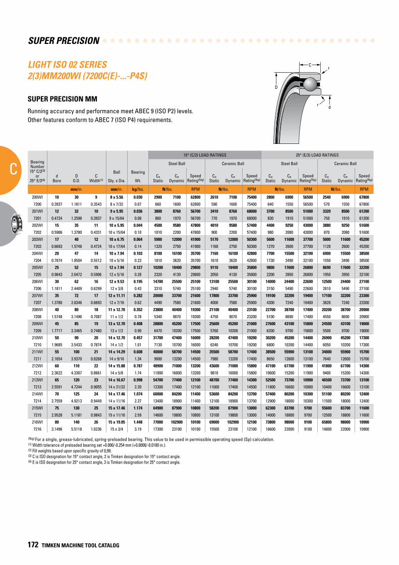
SUPER PRECISION
C
172 TIMKEN MACHINE TOOL CATALOG
C
D
r
dr
(Ng) For a single, grease-lubricated, spring-preloaded bearing. This value to be used in permissible operating speed (Sp) calculation.(1) Width tolerance of preloaded bearing set +0.000/-0.254 mm (+0.0000/-0.0100 in.).(2) Fill weights based upon specific gravity of 0,99.(3) C is ISO designation for 15° contact angle, 2 is Timken designation for 15° contact angle.(4) E is ISO designation for 25° contact angle, 3 is Timken designation for 25° contact angle.
LIGHT ISO 02 SERIES 2(3)MM200WI (7200C(E)-...-P4S)
SUPER PRECISION MM
Running accuracy and performance meet ABEC 9 (ISO P2) levels. Other features conform to ABEC 7 (ISO P4) requirements.
BearingNumber15° C/2(3)
or25° E/3(4)
dBore
DO.D.
CWidth(1)
Ball Bearing
15° (C/2) LOAD RATINGS 25° (E/3) LOAD RATINGS
rRad.(2)
Suggested Shoulder Diameters Shaft Diameter Mounting Fits
FIXED FLOATING
Steel Ball Ceramic Ball Steel Ball Ceramic Ball Housing Bore (Stationary) Mounting Fits Housing Bore
(Stationary) Mounting Fits
CoStatic
CeDynamic
SpeedRating(Ng)
CoStatic
CeDynamic
SpeedRating(Ng)
CoStatic
CeDynamic
SpeedRating(Ng)
CoStatic
CeDynamic
SpeedRating(Ng)
Shaft Housing
Qty. x Dia. Wt. Max. Min. Max. Min. Max. Min. Loose Tight Max. Min. Tight Loose Max. Min. Loose Loose
mm/in. mm/in. kg/lbs. N/lbs. RPM N/lbs. RPM N/lbs. RPM N/lbs. RPM mm/in. mm/in. mm/in. mm/in. mm/in. mm/in. mm/in. mm/in. mm/in.
200WI 10 30 9 8 x 5.56 0.030 2900 7100 62800 2610 7100 75400 2800 6900 56500 2540 6900 67800 0.6 15.1 14.9 26.0 25.8 10.000 9.995 0.005 0.004 30.005 30.000 0.000 0.010 30.010 30.005 0.015 0.005
7200 0.3937 1.1811 0.3543 8 x 7/32 0.07 660 1600 62800 590 1600 75400 640 1550 56500 570 1550 67800 0.024 0.60 0.59 1.03 1.02 0.39370 0.39350 0.00020 0.00015 1.18130 1.18110 0.00000 0.00040 1.18150 1.18130 0.00060 0.00020
201WI 12 32 10 9 x 5.95 0.036 3800 8760 56700 3410 8760 68000 3700 8500 51000 3320 8500 61200 0.6 16.6 16.4 28.1 27.8 12.000 11.995 0.005 0.004 32.005 32.000 0.000 0.011 32.010 32.005 0.016 0.005
7201 0.4724 1.2598 0.3937 9 x 15/64 0.08 860 1970 56700 770 1970 68000 830 1910 51000 750 1910 61200 0.024 0.66 0.65 1.11 1.10 0.47240 0.47220 0.00020 0.00015 1.26000 1.25980 0.00000 0.00045 1.26020 1.26000 0.00070 0.00020
202WI 15 35 11 10 x 5.95 0.044 4500 9580 47800 4010 9580 57400 4400 9250 43000 3880 9250 51600 0.6 19.2 18.9 31.1 30.9 15.000 14.995 0.005 0.004 35.006 35.000 0.000 0.012 35.010 35.005 0.016 0.005
7202 0.5906 1.3780 0.4331 10 x 15/64 0.10 1010 2200 47800 900 2200 57400 980 2080 43000 870 2080 51600 0.024 0.76 0.75 1.23 1.22 0.59060 0.59040 0.00020 0.00015 1.37830 1.37800 0.00000 0.00050 1.37840 1.37820 0.00070 0.00020
203WI 17 40 12 10 x 6.75 0.064 5900 12000 41900 5170 12000 50300 5600 11600 37700 5000 11600 45200 0.6 21.7 21.5 35.7 35.4 17.000 16.995 0.005 0.004 40.006 40.000 0.000 0.012 40.010 40.005 0.016 0.005
7203 0.6693 1.5748 0.4724 10 x 17/64 0.14 1320 2750 41900 1160 2750 50300 1270 2600 37700 1120 2600 45200 0.024 0.86 0.85 1.41 1.40 0.66930 0.66910 0.00020 0.00015 1.57510 1.57480 0.00000 0.00050 1.57520 1.57500 0.00070 0.00020
204WI 20 47 14 10 x 7.94 0.103 8100 16100 35700 7160 16100 42800 7700 15500 32100 6900 15500 38500 1.0 26.0 25.8 41.5 41.3 20.000 19.995 0.005 0.005 47.006 47.000 0.000 0.012 47.012 47.007 0.018 0.007
7204 0.7874 1.8504 0.5512 10 x 5/16 0.23 1810 3620 35700 1610 3620 42800 1730 3490 32100 1550 3490 38500 0.039 1.03 1.02 1.64 1.63 0.78740 0.78720 0.00020 0.00020 1.85070 1.85040 0.00000 0.00050 1.85090 1.85070 0.00080 0.00030
205WI 25 52 15 12 x 7.94 0.127 10200 18400 29800 9110 18400 35800 9800 17600 26800 8690 17600 32200 1.0 31.1 30.9 47.1 46.9 25.000 24.995 0.005 0.005 52.006 52.000 0.000 0.013 52.012 52.007 0.019 0.007
7205 0.9843 2.0472 0.5906 12 x 5/16 0.28 2320 4130 29800 2050 4130 35800 2200 3950 26800 1950 3950 32100 0.039 1.23 1.22 1.86 1.85 0.98430 0.98410 0.00020 0.00020 2.04750 2.04720 0.00000 0.00055 2.04770 2.04750 0.00080 0.00030
206WI 30 62 16 12 x 9.53 0.195 14700 25500 25100 13100 25500 30100 14000 24400 22600 12500 24400 27100 1.0 36.7 36.5 56.0 55.8 30.000 29.995 0.005 0.005 62.008 62.000 0.000 0.015 62.012 62.007 0.019 0.007
7206 1.1811 2.4409 0.6299 12 x 3/8 0.43 3310 5740 25100 2940 5740 30100 3150 5490 22600 2810 5490 27100 0.039 1.45 1.44 2.21 2.20 1.18110 1.18090 0.00020 0.00020 2.44120 2.44090 0.00000 0.00060 2.44140 2.44120 0.00080 0.00030
207WI 35 72 17 12 x 11.11 0.282 20000 33700 21600 17800 33700 25900 19100 32200 19400 17100 32200 23300 1.0 42.7 42.2 65.3 64.8 35.000 34.995 0.005 0.006 72.008 72.000 0.000 0.015 72.011 72.007 0.019 0.007
7207 1.3780 2.8346 0.6693 12 x 7/16 0.62 4490 7580 21600 4000 7580 25900 4300 7240 19400 3820 7240 23300 0.039 1.68 1.66 2.57 2.55 1.37800 1.37780 0.00020 0.00025 2.83490 2.83460 0.00000 0.00060 2.83510 2.83490 0.00080 0.00030
208WI 40 80 18 11 x 12.70 0.352 23800 40400 19300 21100 40400 23100 22700 38700 17400 20200 38700 20900 1.0 47.8 47.2 73.2 72.6 40.000 39.995 0.005 0.006 80.008 80.000 0.000 0.015 80.012 80.008 0.020 0.008
7208 1.5748 3.1496 0.7087 11 x 1/2 0.78 5340 9070 19300 4750 9070 23200 5100 8690 17400 4550 8690 20900 0.039 1.88 1.86 2.88 2.86 1.57480 1.57460 0.00020 0.00025 3.14990 3.14960 0.00000 0.00060 3.15010 3.14990 0.00080 0.00030
209WI 45 85 19 13 x 12.70 0.408 28800 45200 17500 25600 45200 21000 27600 43100 15800 24500 43100 19000 1.0 52.8 52.3 78.2 77.7 45.000 44.995 0.005 0.006 85.008 85.000 0.000 0.016 85.016 85.009 0.024 0.009
7209 1.7717 3.3465 0.7480 13 x 1/2 0.90 6470 10200 17500 5760 10200 21000 6200 9700 15800 5500 9700 19000 0.039 2.08 2.06 3.08 3.06 1.77170 1.77150 0.00020 0.00025 3.34680 3.34650 0.00000 0.00060 3.34710 3.34680 0.00090 0.00030
210WI 50 90 20 14 x 12.70 0.457 31700 47400 16000 28200 47400 19200 30200 45200 14400 26900 45200 17300 1.0 57.9 57.4 83.3 82.8 50.000 49.995 0.005 0.006 90.008 90.000 0.000 0.016 90.015 90.007 0.023 0.007
7210 1.9685 3.5433 0.7874 14 x 1/2 1.01 7130 10700 16000 6340 10700 19200 6800 10200 14400 6050 10200 17300 0.039 2.28 2.26 3.28 3.26 1.96850 1.96830 0.00020 0.00025 3.54360 3.54330 0.00000 0.00060 3.54390 3.54360 0.00090 0.00030
211WI 55 100 21 14 x 14.29 0.608 40000 58700 14500 35500 58700 17400 38500 55900 13100 34000 55900 15700 1.5 63.8 63.3 92.2 91.7 55.000 54.995 0.005 0.007 100.008 100.000 0.000 0.016 100.018 100.010 0.025 0.010
7211 2.1654 3.9370 0.8268 14 x 9/16 1.34 9000 13200 14500 7980 13200 17400 8650 12600 13100 7640 12600 15700 0.059 2.51 2.49 3.63 3.61 2.16540 2.16520 0.00020 0.00030 3.93730 3.93700 0.00000 0.00060 3.93770 3.93740 0.00100 0.00040
212WI 60 110 22 14 x 15.88 0.787 48900 71000 13200 43600 71000 15800 47100 67700 11900 41800 67700 14300 1.5 69.9 69.3 101.4 100.8 60.000 59.995 0.005 0.007 110.008 110.000 0.000 0.016 110.018 110.010 0.025 0.010
7212 2.3622 4.3307 0.8661 14 x 5/8 1.74 11000 16000 13200 9810 16000 15800 10600 15200 11900 9400 15200 14300 0.059 2.75 2.73 3.99 3.97 2.36220 2.36200 0.00020 0.00030 4.33100 4.33070 0.00000 0.00060 4.33140 4.33110 0.00100 0.00040
213WI 65 120 23 14 x 16.67 0.998 54700 77400 12100 48700 77400 14300 52500 73700 10900 46500 73700 13100 1.5 76.2 75.7 109.7 109.2 65.000 64.995 0.005 0.007 120.008 120.000 0.000 0.016 120.018 120.010 0.025 0.010
7213 2.5591 4.7244 0.9055 14 x 21/32 2.20 12300 17400 12100 11000 17400 14500 11800 16600 10900 10400 16600 13100 0.059 3.00 2.98 4.32 4.30 2.55910 2.55890 0.00020 0.00030 4.72470 4.72440 0.00000 0.00060 4.72510 4.72480 0.00100 0.00040
214WI 70 125 24 14 x 17.46 1.074 60000 84200 11400 53600 84200 13700 57400 80200 10300 51100 80200 12400 1.5 80.8 80.3 115.8 115.3 70.000 69.995 0.005 0.007 125.008 125.000 0.000 0.017 125.021 125.011 0.030 0.011
7214 2.7559 4.9213 0.9449 14 x 11/16 2.37 13400 18900 11400 12100 18900 13700 12900 18000 10300 11500 18000 12400 0.059 3.18 3.16 4.56 4.54 2.75590 2.75570 0.00020 0.00030 4.92160 4.92130 0.00000 0.00070 4.92210 4.92170 0.00120 0.00040
215WI 75 130 25 15 x 17.46 1.174 64900 87900 10800 58200 87900 13000 62300 83700 9700 55600 83700 11600 1.5 86.0 85.2 120.8 120.0 75.005 74.995 0.005 0.012 130.009 130.000 0.000 0.018 130.020 130.010 0.029 0.010
7215 2.9528 5.1181 0.9843 15 x 11/16 2.59 14600 19800 10800 13100 19800 13000 14000 18800 9700 12500 18800 11600 0.059 3.39 3.36 4.76 4.73 2.95300 2.95260 0.00020 0.00050 5.11850 5.11810 0.00000 0.00070 5.11890 5.11850 0.00110 0.00040
216WI 80 140 26 15 x 19.05 1.448 77000 102900 10100 69000 102900 12100 73800 98000 9100 65800 98000 10900 2.0 91.3 90.6 129.9 129.2 80.005 79.995 0.005 0.012 140.009 140.000 0.000 0.018 140.020 140.010 0.029 0.010
7216 3.1496 5.5118 1.0236 15 x 3/4 3.19 17300 23100 10100 15500 23100 12100 16600 22000 9100 14800 22000 10900 0.079 3.60 3.57 5.12 5.09 3.14980 3.14940 0.00020 0.00050 5.51220 5.51180 0.00000 0.00070 5.51260 5.51220 0.00110 0.00040
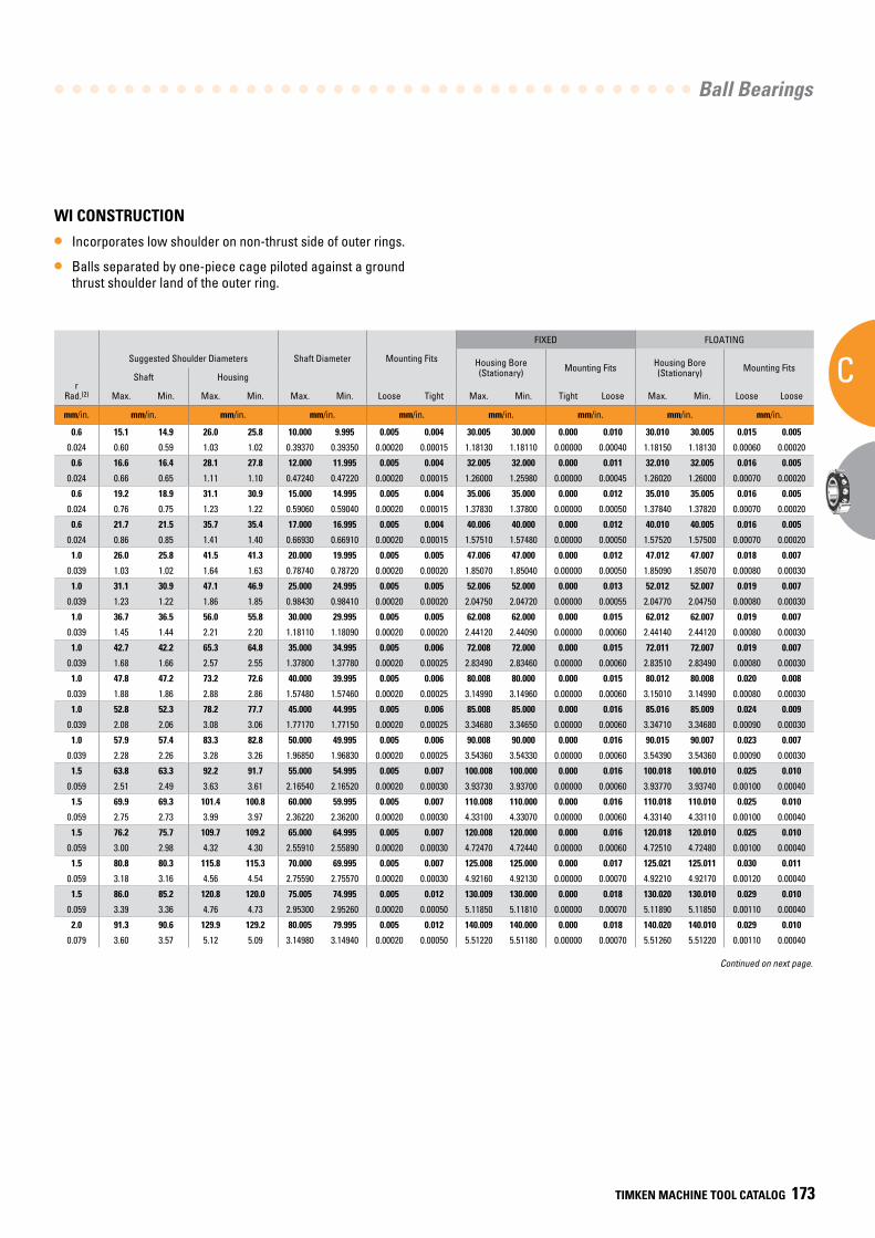
Ball Bearings
C
TIMKEN MACHINE TOOL CATALOG 173
WI CONSTRUCTION
• Incorporates low shoulder on non-thrust side of outer rings.
• Balls separated by one-piece cage piloted against a ground thrust shoulder land of the outer ring.
BearingNumber15° C/2(3)
or25° E/3(4)
dBore
DO.D.
CWidth(1)
Ball Bearing
15° (C/2) LOAD RATINGS 25° (E/3) LOAD RATINGS
rRad.(2)
Suggested Shoulder Diameters Shaft Diameter Mounting Fits
FIXED FLOATING
Steel Ball Ceramic Ball Steel Ball Ceramic Ball Housing Bore (Stationary) Mounting Fits Housing Bore
(Stationary) Mounting Fits
CoStatic
CeDynamic
SpeedRating(Ng)
CoStatic
CeDynamic
SpeedRating(Ng)
CoStatic
CeDynamic
SpeedRating(Ng)
CoStatic
CeDynamic
SpeedRating(Ng)
Shaft Housing
Qty. x Dia. Wt. Max. Min. Max. Min. Max. Min. Loose Tight Max. Min. Tight Loose Max. Min. Loose Loose
mm/in. mm/in. kg/lbs. N/lbs. RPM N/lbs. RPM N/lbs. RPM N/lbs. RPM mm/in. mm/in. mm/in. mm/in. mm/in. mm/in. mm/in. mm/in. mm/in.
200WI 10 30 9 8 x 5.56 0.030 2900 7100 62800 2610 7100 75400 2800 6900 56500 2540 6900 67800 0.6 15.1 14.9 26.0 25.8 10.000 9.995 0.005 0.004 30.005 30.000 0.000 0.010 30.010 30.005 0.015 0.005
7200 0.3937 1.1811 0.3543 8 x 7/32 0.07 660 1600 62800 590 1600 75400 640 1550 56500 570 1550 67800 0.024 0.60 0.59 1.03 1.02 0.39370 0.39350 0.00020 0.00015 1.18130 1.18110 0.00000 0.00040 1.18150 1.18130 0.00060 0.00020
201WI 12 32 10 9 x 5.95 0.036 3800 8760 56700 3410 8760 68000 3700 8500 51000 3320 8500 61200 0.6 16.6 16.4 28.1 27.8 12.000 11.995 0.005 0.004 32.005 32.000 0.000 0.011 32.010 32.005 0.016 0.005
7201 0.4724 1.2598 0.3937 9 x 15/64 0.08 860 1970 56700 770 1970 68000 830 1910 51000 750 1910 61200 0.024 0.66 0.65 1.11 1.10 0.47240 0.47220 0.00020 0.00015 1.26000 1.25980 0.00000 0.00045 1.26020 1.26000 0.00070 0.00020
202WI 15 35 11 10 x 5.95 0.044 4500 9580 47800 4010 9580 57400 4400 9250 43000 3880 9250 51600 0.6 19.2 18.9 31.1 30.9 15.000 14.995 0.005 0.004 35.006 35.000 0.000 0.012 35.010 35.005 0.016 0.005
7202 0.5906 1.3780 0.4331 10 x 15/64 0.10 1010 2200 47800 900 2200 57400 980 2080 43000 870 2080 51600 0.024 0.76 0.75 1.23 1.22 0.59060 0.59040 0.00020 0.00015 1.37830 1.37800 0.00000 0.00050 1.37840 1.37820 0.00070 0.00020
203WI 17 40 12 10 x 6.75 0.064 5900 12000 41900 5170 12000 50300 5600 11600 37700 5000 11600 45200 0.6 21.7 21.5 35.7 35.4 17.000 16.995 0.005 0.004 40.006 40.000 0.000 0.012 40.010 40.005 0.016 0.005
7203 0.6693 1.5748 0.4724 10 x 17/64 0.14 1320 2750 41900 1160 2750 50300 1270 2600 37700 1120 2600 45200 0.024 0.86 0.85 1.41 1.40 0.66930 0.66910 0.00020 0.00015 1.57510 1.57480 0.00000 0.00050 1.57520 1.57500 0.00070 0.00020
204WI 20 47 14 10 x 7.94 0.103 8100 16100 35700 7160 16100 42800 7700 15500 32100 6900 15500 38500 1.0 26.0 25.8 41.5 41.3 20.000 19.995 0.005 0.005 47.006 47.000 0.000 0.012 47.012 47.007 0.018 0.007
7204 0.7874 1.8504 0.5512 10 x 5/16 0.23 1810 3620 35700 1610 3620 42800 1730 3490 32100 1550 3490 38500 0.039 1.03 1.02 1.64 1.63 0.78740 0.78720 0.00020 0.00020 1.85070 1.85040 0.00000 0.00050 1.85090 1.85070 0.00080 0.00030
205WI 25 52 15 12 x 7.94 0.127 10200 18400 29800 9110 18400 35800 9800 17600 26800 8690 17600 32200 1.0 31.1 30.9 47.1 46.9 25.000 24.995 0.005 0.005 52.006 52.000 0.000 0.013 52.012 52.007 0.019 0.007
7205 0.9843 2.0472 0.5906 12 x 5/16 0.28 2320 4130 29800 2050 4130 35800 2200 3950 26800 1950 3950 32100 0.039 1.23 1.22 1.86 1.85 0.98430 0.98410 0.00020 0.00020 2.04750 2.04720 0.00000 0.00055 2.04770 2.04750 0.00080 0.00030
206WI 30 62 16 12 x 9.53 0.195 14700 25500 25100 13100 25500 30100 14000 24400 22600 12500 24400 27100 1.0 36.7 36.5 56.0 55.8 30.000 29.995 0.005 0.005 62.008 62.000 0.000 0.015 62.012 62.007 0.019 0.007
7206 1.1811 2.4409 0.6299 12 x 3/8 0.43 3310 5740 25100 2940 5740 30100 3150 5490 22600 2810 5490 27100 0.039 1.45 1.44 2.21 2.20 1.18110 1.18090 0.00020 0.00020 2.44120 2.44090 0.00000 0.00060 2.44140 2.44120 0.00080 0.00030
207WI 35 72 17 12 x 11.11 0.282 20000 33700 21600 17800 33700 25900 19100 32200 19400 17100 32200 23300 1.0 42.7 42.2 65.3 64.8 35.000 34.995 0.005 0.006 72.008 72.000 0.000 0.015 72.011 72.007 0.019 0.007
7207 1.3780 2.8346 0.6693 12 x 7/16 0.62 4490 7580 21600 4000 7580 25900 4300 7240 19400 3820 7240 23300 0.039 1.68 1.66 2.57 2.55 1.37800 1.37780 0.00020 0.00025 2.83490 2.83460 0.00000 0.00060 2.83510 2.83490 0.00080 0.00030
208WI 40 80 18 11 x 12.70 0.352 23800 40400 19300 21100 40400 23100 22700 38700 17400 20200 38700 20900 1.0 47.8 47.2 73.2 72.6 40.000 39.995 0.005 0.006 80.008 80.000 0.000 0.015 80.012 80.008 0.020 0.008
7208 1.5748 3.1496 0.7087 11 x 1/2 0.78 5340 9070 19300 4750 9070 23200 5100 8690 17400 4550 8690 20900 0.039 1.88 1.86 2.88 2.86 1.57480 1.57460 0.00020 0.00025 3.14990 3.14960 0.00000 0.00060 3.15010 3.14990 0.00080 0.00030
209WI 45 85 19 13 x 12.70 0.408 28800 45200 17500 25600 45200 21000 27600 43100 15800 24500 43100 19000 1.0 52.8 52.3 78.2 77.7 45.000 44.995 0.005 0.006 85.008 85.000 0.000 0.016 85.016 85.009 0.024 0.009
7209 1.7717 3.3465 0.7480 13 x 1/2 0.90 6470 10200 17500 5760 10200 21000 6200 9700 15800 5500 9700 19000 0.039 2.08 2.06 3.08 3.06 1.77170 1.77150 0.00020 0.00025 3.34680 3.34650 0.00000 0.00060 3.34710 3.34680 0.00090 0.00030
210WI 50 90 20 14 x 12.70 0.457 31700 47400 16000 28200 47400 19200 30200 45200 14400 26900 45200 17300 1.0 57.9 57.4 83.3 82.8 50.000 49.995 0.005 0.006 90.008 90.000 0.000 0.016 90.015 90.007 0.023 0.007
7210 1.9685 3.5433 0.7874 14 x 1/2 1.01 7130 10700 16000 6340 10700 19200 6800 10200 14400 6050 10200 17300 0.039 2.28 2.26 3.28 3.26 1.96850 1.96830 0.00020 0.00025 3.54360 3.54330 0.00000 0.00060 3.54390 3.54360 0.00090 0.00030
211WI 55 100 21 14 x 14.29 0.608 40000 58700 14500 35500 58700 17400 38500 55900 13100 34000 55900 15700 1.5 63.8 63.3 92.2 91.7 55.000 54.995 0.005 0.007 100.008 100.000 0.000 0.016 100.018 100.010 0.025 0.010
7211 2.1654 3.9370 0.8268 14 x 9/16 1.34 9000 13200 14500 7980 13200 17400 8650 12600 13100 7640 12600 15700 0.059 2.51 2.49 3.63 3.61 2.16540 2.16520 0.00020 0.00030 3.93730 3.93700 0.00000 0.00060 3.93770 3.93740 0.00100 0.00040
212WI 60 110 22 14 x 15.88 0.787 48900 71000 13200 43600 71000 15800 47100 67700 11900 41800 67700 14300 1.5 69.9 69.3 101.4 100.8 60.000 59.995 0.005 0.007 110.008 110.000 0.000 0.016 110.018 110.010 0.025 0.010
7212 2.3622 4.3307 0.8661 14 x 5/8 1.74 11000 16000 13200 9810 16000 15800 10600 15200 11900 9400 15200 14300 0.059 2.75 2.73 3.99 3.97 2.36220 2.36200 0.00020 0.00030 4.33100 4.33070 0.00000 0.00060 4.33140 4.33110 0.00100 0.00040
213WI 65 120 23 14 x 16.67 0.998 54700 77400 12100 48700 77400 14300 52500 73700 10900 46500 73700 13100 1.5 76.2 75.7 109.7 109.2 65.000 64.995 0.005 0.007 120.008 120.000 0.000 0.016 120.018 120.010 0.025 0.010
7213 2.5591 4.7244 0.9055 14 x 21/32 2.20 12300 17400 12100 11000 17400 14500 11800 16600 10900 10400 16600 13100 0.059 3.00 2.98 4.32 4.30 2.55910 2.55890 0.00020 0.00030 4.72470 4.72440 0.00000 0.00060 4.72510 4.72480 0.00100 0.00040
214WI 70 125 24 14 x 17.46 1.074 60000 84200 11400 53600 84200 13700 57400 80200 10300 51100 80200 12400 1.5 80.8 80.3 115.8 115.3 70.000 69.995 0.005 0.007 125.008 125.000 0.000 0.017 125.021 125.011 0.030 0.011
7214 2.7559 4.9213 0.9449 14 x 11/16 2.37 13400 18900 11400 12100 18900 13700 12900 18000 10300 11500 18000 12400 0.059 3.18 3.16 4.56 4.54 2.75590 2.75570 0.00020 0.00030 4.92160 4.92130 0.00000 0.00070 4.92210 4.92170 0.00120 0.00040
215WI 75 130 25 15 x 17.46 1.174 64900 87900 10800 58200 87900 13000 62300 83700 9700 55600 83700 11600 1.5 86.0 85.2 120.8 120.0 75.005 74.995 0.005 0.012 130.009 130.000 0.000 0.018 130.020 130.010 0.029 0.010
7215 2.9528 5.1181 0.9843 15 x 11/16 2.59 14600 19800 10800 13100 19800 13000 14000 18800 9700 12500 18800 11600 0.059 3.39 3.36 4.76 4.73 2.95300 2.95260 0.00020 0.00050 5.11850 5.11810 0.00000 0.00070 5.11890 5.11850 0.00110 0.00040
216WI 80 140 26 15 x 19.05 1.448 77000 102900 10100 69000 102900 12100 73800 98000 9100 65800 98000 10900 2.0 91.3 90.6 129.9 129.2 80.005 79.995 0.005 0.012 140.009 140.000 0.000 0.018 140.020 140.010 0.029 0.010
7216 3.1496 5.5118 1.0236 15 x 3/4 3.19 17300 23100 10100 15500 23100 12100 16600 22000 9100 14800 22000 10900 0.079 3.60 3.57 5.12 5.09 3.14980 3.14940 0.00020 0.00050 5.51220 5.51180 0.00000 0.00070 5.51260 5.51220 0.00110 0.00040
Continued on next page.
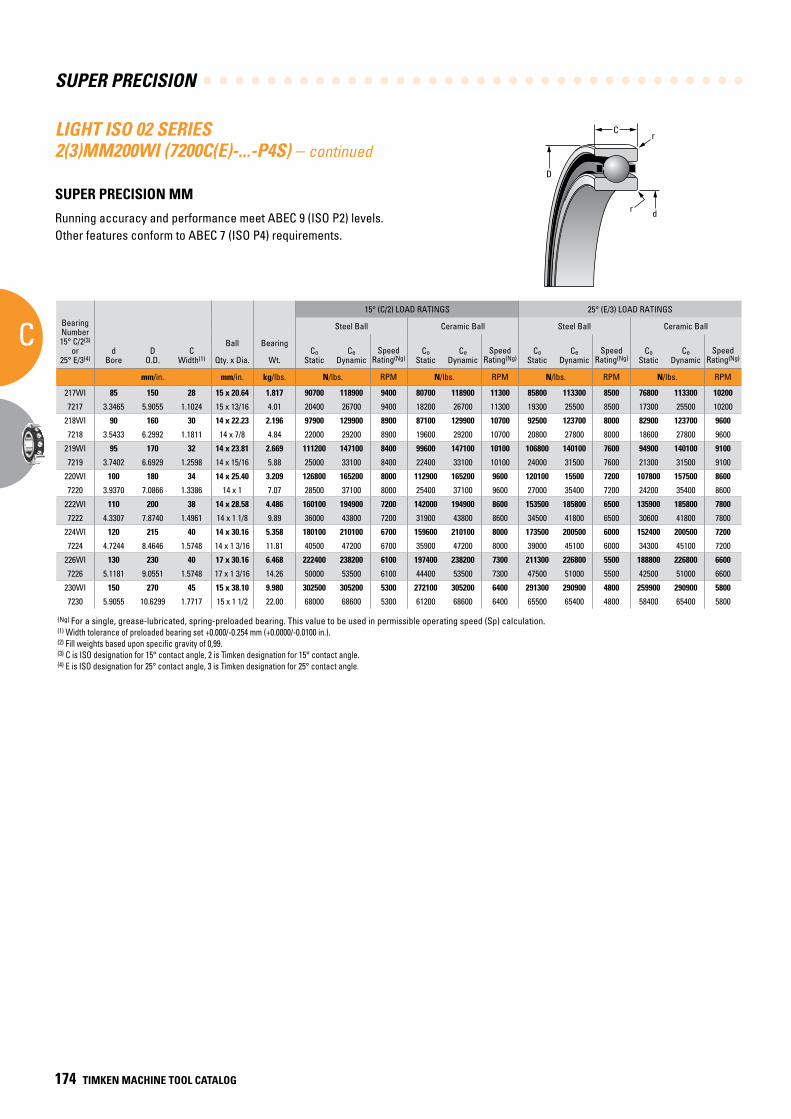
SUPER PRECISION
C
174 TIMKEN MACHINE TOOL CATALOG
C
D
r
dr
(Ng) For a single, grease-lubricated, spring-preloaded bearing. This value to be used in permissible operating speed (Sp) calculation.(1) Width tolerance of preloaded bearing set +0.000/-0.254 mm (+0.0000/-0.0100 in.).(2) Fill weights based upon specific gravity of 0,99.(3) C is ISO designation for 15° contact angle, 2 is Timken designation for 15° contact angle.(4) E is ISO designation for 25° contact angle, 3 is Timken designation for 25° contact angle.
BearingNumber15° C/2(3)
or25° E/3(4)
dBore
DO.D.
CWidth(1)
Ball Bearing
15° (C/2) LOAD RATINGS 25° (E/3) LOAD RATINGS
rRad.(2)
Suggested Shoulder Diameters Shaft Diameter Mounting Fits
FIXED FLOATING
Steel Ball Ceramic Ball Steel Ball Ceramic Ball Housing Bore (Stationary) Mounting Fits Housing Bore
(Stationary) Mounting Fits
CoStatic
CeDynamic
SpeedRating(Ng)
CoStatic
CeDynamic
SpeedRating(Ng)
CoStatic
CeDynamic
SpeedRating(Ng)
CoStatic
CeDynamic
SpeedRating(Ng)
Shaft Housing
Qty. x Dia. Wt. Max. Min. Max. Min. Max. Min. Loose Tight Max. Min. Tight Loose Max. Min. Loose Loose
mm/in. mm/in. kg/lbs. N/lbs. RPM N/lbs. RPM N/lbs. RPM N/lbs. RPM mm/in. mm/in. mm/in. mm/in. mm/in. mm/in. mm/in. mm/in. mm/in.
217WI 85 150 28 15 x 20.64 1.817 90700 118900 9400 80700 118900 11300 85800 113300 8500 76800 113300 10200 2.0 97.4 96.7 138.8 138.1 85.005 84.995 0.005 0.012 150.009 150.000 0.000 0.018 150.023 150.012 0.032 0.012
7217 3.3465 5.9055 1.1024 15 x 13/16 4.01 20400 26700 9400 18200 26700 11300 19300 25500 8500 17300 25500 10200 0.079 3.84 3.81 5.47 5.44 3.34670 3.34630 0.00020 0.00050 5.90590 5.90550 0.00000 0.00070 5.90640 5.90600 0.00120 0.00050
218WI 90 160 30 14 x 22.23 2.196 97900 129900 8900 87100 129900 10700 92500 123700 8000 82900 123700 9600 2.0 103.5 102.7 148.0 147.2 90.005 89.995 0.005 0.013 160.009 160.000 0.000 0.022 160.022 160.012 0.033 0.012
7218 3.5433 6.2992 1.1811 14 x 7/8 4.84 22000 29200 8900 19600 29200 10700 20800 27800 8000 18600 27800 9600 0.079 4.08 4.05 5.83 5.80 3.54350 3.54310 0.00020 0.00050 6.29960 6.29920 0.00000 0.00080 6.30010 6.29970 0.00130 0.00050
219WI 95 170 32 14 x 23.81 2.669 111200 147100 8400 99600 147100 10100 106800 140100 7600 94900 140100 9100 2.1 109.4 108.6 157.1 153.3 95.005 94.995 0.005 0.013 170.010 170.000 0.000 0.020 170.022 170.012 0.032 0.012
7219 3.7402 6.6929 1.2598 14 x 15/16 5.88 25000 33100 8400 22400 33100 10100 24000 31500 7600 21300 31500 9100 0.079 4.31 4.28 6.19 6.16 3.74040 3.74000 0.00020 0.00050 6.69330 6.69290 0.00000 0.00080 6.69380 6.69340 0.00130 0.00050
220WI 100 180 34 14 x 25.40 3.209 126800 165200 8000 112900 165200 9600 120100 15500 7200 107800 157500 8600 2.1 115.2 114.4 166.0 165.2 100.005 99.995 0.005 0.013 180.010 180.000 0.000 0.020 180.022 180.012 0.032 0.012
7220 3.9370 7.0866 1.3386 14 x 1 7.07 28500 37100 8000 25400 37100 9600 27000 35400 7200 24200 35400 8600 0.079 4.54 4.51 6.54 6.51 3.93720 3.93680 0.00020 0.00050 7.08700 7.08660 0.00000 0.00080 7.08750 7.08710 0.00130 0.00050
222WI 110 200 38 14 x 28.58 4.486 160100 194900 7200 142000 194900 8600 153500 185800 6500 135900 185800 7800 2.1 127.1 126.4 184.3 183.5 110.005 109.995 0.005 0.013 200.011 200.000 0.000 0.022 200.025 200.015 0.036 0.015
7222 4.3307 7.8740 1.4961 14 x 1 1/8 9.89 36000 43800 7200 31900 43800 8600 34500 41800 6500 30600 41800 7800 0.079 5.01 4.98 7.26 7.23 4.33090 4.33050 0.00020 0.00050 7.87450 7.87400 0.00000 0.00090 7.87500 7.87460 0.00150 0.00060
224WI 120 215 40 14 x 30.16 5.358 180100 210100 6700 159600 210100 8000 173500 200500 6000 152400 200500 7200 2.1 138.1 137.3 198.5 197.7 120.005 119.995 0.005 0.013 215.011 215.000 0.000 0.022 215.025 215.015 0.036 0.015
7224 4.7244 8.4646 1.5748 14 x 1 3/16 11.81 40500 47200 6700 35900 47200 8000 39000 45100 6000 34300 45100 7200 0.079 5.44 5.41 7.82 7.79 4.72460 4.72420 0.00020 0.00050 8.46510 8.46460 0.00000 0.00090 8.46560 8.46520 0.00150 0.00060
226WI 130 230 40 17 x 30.16 6.468 222400 238200 6100 197400 238200 7300 211300 226800 5500 188800 226800 6600 2.5 150.5 149.7 211.0 210.2 130.005 129.995 0.005 0.015 230.011 230.000 0.000 0.022 230.025 230.015 0.036 0.015
7226 5.1181 9.0551 1.5748 17 x 1 3/16 14.26 50000 53500 6100 44400 53500 7300 47500 51000 5500 42500 51000 6600 0.098 5.93 5.90 8.31 8.28 5.11830 5.11790 0.00020 0.00060 9.05560 9.05510 0.00000 0.00090 9.05610 9.05570 0.00150 0.00060
230WI 150 270 45 15 x 38.10 9.980 302500 305200 5300 272100 305200 6400 291300 290900 4800 259900 290900 5800 2.5 172.6 171.8 248.8 248.0 150.005 149.995 0.005 0.015 270.013 270.000 0.000 0.026 270.031 270.018 0.044 0.018
7230 5.9055 10.6299 1.7717 15 x 1 1/2 22.00 68000 68600 5300 61200 68600 6400 65500 65400 4800 58400 65400 5800 0.098 6.80 6.77 9.80 9.77 5.90570 5.90530 0.00020 0.00060 10.63040 10.62990 0.00000 0.00100 10.63120 10.63070 0.00180 0.00080
LIGHT ISO 02 SERIES 2(3)MM200WI (7200C(E)-...-P4S) – continued
SUPER PRECISION MM
Running accuracy and performance meet ABEC 9 (ISO P2) levels. Other features conform to ABEC 7 (ISO P4) requirements.
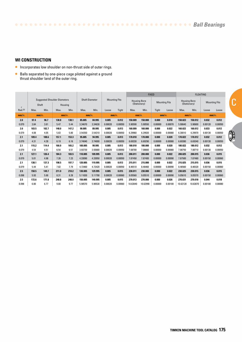
Ball Bearings
C
TIMKEN MACHINE TOOL CATALOG 175
BearingNumber15° C/2(3)
or25° E/3(4)
dBore
DO.D.
CWidth(1)
Ball Bearing
15° (C/2) LOAD RATINGS 25° (E/3) LOAD RATINGS
rRad.(2)
Suggested Shoulder Diameters Shaft Diameter Mounting Fits
FIXED FLOATING
Steel Ball Ceramic Ball Steel Ball Ceramic Ball Housing Bore (Stationary) Mounting Fits Housing Bore
(Stationary) Mounting Fits
CoStatic
CeDynamic
SpeedRating(Ng)
CoStatic
CeDynamic
SpeedRating(Ng)
CoStatic
CeDynamic
SpeedRating(Ng)
CoStatic
CeDynamic
SpeedRating(Ng)
Shaft Housing
Qty. x Dia. Wt. Max. Min. Max. Min. Max. Min. Loose Tight Max. Min. Tight Loose Max. Min. Loose Loose
mm/in. mm/in. kg/lbs. N/lbs. RPM N/lbs. RPM N/lbs. RPM N/lbs. RPM mm/in. mm/in. mm/in. mm/in. mm/in. mm/in. mm/in. mm/in. mm/in.
217WI 85 150 28 15 x 20.64 1.817 90700 118900 9400 80700 118900 11300 85800 113300 8500 76800 113300 10200 2.0 97.4 96.7 138.8 138.1 85.005 84.995 0.005 0.012 150.009 150.000 0.000 0.018 150.023 150.012 0.032 0.012
7217 3.3465 5.9055 1.1024 15 x 13/16 4.01 20400 26700 9400 18200 26700 11300 19300 25500 8500 17300 25500 10200 0.079 3.84 3.81 5.47 5.44 3.34670 3.34630 0.00020 0.00050 5.90590 5.90550 0.00000 0.00070 5.90640 5.90600 0.00120 0.00050
218WI 90 160 30 14 x 22.23 2.196 97900 129900 8900 87100 129900 10700 92500 123700 8000 82900 123700 9600 2.0 103.5 102.7 148.0 147.2 90.005 89.995 0.005 0.013 160.009 160.000 0.000 0.022 160.022 160.012 0.033 0.012
7218 3.5433 6.2992 1.1811 14 x 7/8 4.84 22000 29200 8900 19600 29200 10700 20800 27800 8000 18600 27800 9600 0.079 4.08 4.05 5.83 5.80 3.54350 3.54310 0.00020 0.00050 6.29960 6.29920 0.00000 0.00080 6.30010 6.29970 0.00130 0.00050
219WI 95 170 32 14 x 23.81 2.669 111200 147100 8400 99600 147100 10100 106800 140100 7600 94900 140100 9100 2.1 109.4 108.6 157.1 153.3 95.005 94.995 0.005 0.013 170.010 170.000 0.000 0.020 170.022 170.012 0.032 0.012
7219 3.7402 6.6929 1.2598 14 x 15/16 5.88 25000 33100 8400 22400 33100 10100 24000 31500 7600 21300 31500 9100 0.079 4.31 4.28 6.19 6.16 3.74040 3.74000 0.00020 0.00050 6.69330 6.69290 0.00000 0.00080 6.69380 6.69340 0.00130 0.00050
220WI 100 180 34 14 x 25.40 3.209 126800 165200 8000 112900 165200 9600 120100 15500 7200 107800 157500 8600 2.1 115.2 114.4 166.0 165.2 100.005 99.995 0.005 0.013 180.010 180.000 0.000 0.020 180.022 180.012 0.032 0.012
7220 3.9370 7.0866 1.3386 14 x 1 7.07 28500 37100 8000 25400 37100 9600 27000 35400 7200 24200 35400 8600 0.079 4.54 4.51 6.54 6.51 3.93720 3.93680 0.00020 0.00050 7.08700 7.08660 0.00000 0.00080 7.08750 7.08710 0.00130 0.00050
222WI 110 200 38 14 x 28.58 4.486 160100 194900 7200 142000 194900 8600 153500 185800 6500 135900 185800 7800 2.1 127.1 126.4 184.3 183.5 110.005 109.995 0.005 0.013 200.011 200.000 0.000 0.022 200.025 200.015 0.036 0.015
7222 4.3307 7.8740 1.4961 14 x 1 1/8 9.89 36000 43800 7200 31900 43800 8600 34500 41800 6500 30600 41800 7800 0.079 5.01 4.98 7.26 7.23 4.33090 4.33050 0.00020 0.00050 7.87450 7.87400 0.00000 0.00090 7.87500 7.87460 0.00150 0.00060
224WI 120 215 40 14 x 30.16 5.358 180100 210100 6700 159600 210100 8000 173500 200500 6000 152400 200500 7200 2.1 138.1 137.3 198.5 197.7 120.005 119.995 0.005 0.013 215.011 215.000 0.000 0.022 215.025 215.015 0.036 0.015
7224 4.7244 8.4646 1.5748 14 x 1 3/16 11.81 40500 47200 6700 35900 47200 8000 39000 45100 6000 34300 45100 7200 0.079 5.44 5.41 7.82 7.79 4.72460 4.72420 0.00020 0.00050 8.46510 8.46460 0.00000 0.00090 8.46560 8.46520 0.00150 0.00060
226WI 130 230 40 17 x 30.16 6.468 222400 238200 6100 197400 238200 7300 211300 226800 5500 188800 226800 6600 2.5 150.5 149.7 211.0 210.2 130.005 129.995 0.005 0.015 230.011 230.000 0.000 0.022 230.025 230.015 0.036 0.015
7226 5.1181 9.0551 1.5748 17 x 1 3/16 14.26 50000 53500 6100 44400 53500 7300 47500 51000 5500 42500 51000 6600 0.098 5.93 5.90 8.31 8.28 5.11830 5.11790 0.00020 0.00060 9.05560 9.05510 0.00000 0.00090 9.05610 9.05570 0.00150 0.00060
230WI 150 270 45 15 x 38.10 9.980 302500 305200 5300 272100 305200 6400 291300 290900 4800 259900 290900 5800 2.5 172.6 171.8 248.8 248.0 150.005 149.995 0.005 0.015 270.013 270.000 0.000 0.026 270.031 270.018 0.044 0.018
7230 5.9055 10.6299 1.7717 15 x 1 1/2 22.00 68000 68600 5300 61200 68600 6400 65500 65400 4800 58400 65400 5800 0.098 6.80 6.77 9.80 9.77 5.90570 5.90530 0.00020 0.00060 10.63040 10.62990 0.00000 0.00100 10.63120 10.63070 0.00180 0.00080
WI CONSTRUCTION
• Incorporates low shoulder on non-thrust side of outer rings.
• Balls separated by one-piece cage piloted against a ground thrust shoulder land of the outer ring.
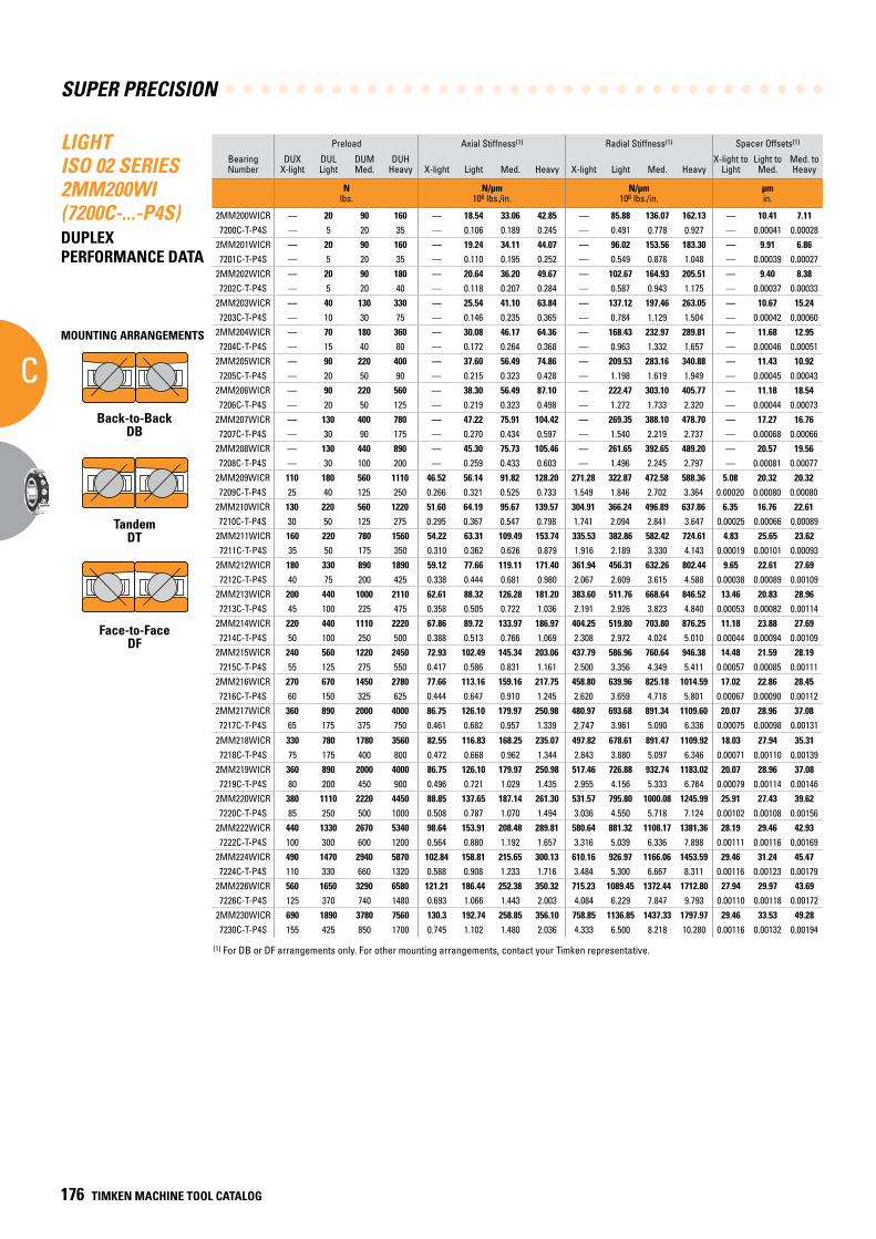
SUPER PRECISION
C
176 TIMKEN MACHINE TOOL CATALOG
LIGHT ISO 02 SERIES 2MM200WI (7200C-...-P4S)DUPLEX PERFORMANCE DATA
Preload Axial Stiffness(1) Radial Stiffness(1) Spacer Offsets(1)
Bearing Number
DUXX-light
DULLight
DUMMed.
DUHHeavy X-light Light Med. Heavy X-light Light Med. Heavy
X-light toLight
Light toMed.
Med. toHeavy
N lbs.
N/µm 106 lbs./in.
N/µm 106 lbs./in.
µm in.
2MM200WICR — 20 90 160 — 18.54 33.06 42.85 — 85.88 136.07 162.13 — 10.41 7.117200C-T-P4S — 5 20 35 — 0.106 0.189 0.245 — 0.491 0.778 0.927 — 0.00041 0.00028
2MM201WICR — 20 90 160 — 19.24 34.11 44.07 — 96.02 153.56 183.30 — 9.91 6.867201C-T-P4S — 5 20 35 — 0.110 0.195 0.252 — 0.549 0.878 1.048 — 0.00039 0.00027
2MM202WICR — 20 90 180 — 20.64 36.20 49.67 — 102.67 164.93 205.51 — 9.40 8.387202C-T-P4S — 5 20 40 — 0.118 0.207 0.284 — 0.587 0.943 1.175 — 0.00037 0.00033
2MM203WICR — 40 130 330 — 25.54 41.10 63.84 — 137.12 197.46 263.05 — 10.67 15.247203C-T-P4S — 10 30 75 — 0.146 0.235 0.365 — 0.784 1.129 1.504 — 0.00042 0.00060
2MM204WICR — 70 180 360 — 30.08 46.17 64.36 — 168.43 232.97 289.81 — 11.68 12.957204C-T-P4S — 15 40 80 — 0.172 0.264 0.368 — 0.963 1.332 1.657 — 0.00046 0.00051
2MM205WICR — 90 220 400 — 37.60 56.49 74.86 — 209.53 283.16 340.88 — 11.43 10.927205C-T-P4S — 20 50 90 — 0.215 0.323 0.428 — 1.198 1.619 1.949 — 0.00045 0.00043
2MM206WICR — 90 220 560 — 38.30 56.49 87.10 — 222.47 303.10 405.77 — 11.18 18.547206C-T-P4S — 20 50 125 — 0.219 0.323 0.498 — 1.272 1.733 2.320 — 0.00044 0.00073
2MM207WICR — 130 400 780 — 47.22 75.91 104.42 — 269.35 388.10 478.70 — 17.27 16.767207C-T-P4S — 30 90 175 — 0.270 0.434 0.597 — 1.540 2.219 2.737 — 0.00068 0.00066
2MM208WICR — 130 440 890 — 45.30 75.73 105.46 — 261.65 392.65 489.20 — 20.57 19.567208C-T-P4S — 30 100 200 — 0.259 0.433 0.603 — 1.496 2.245 2.797 — 0.00081 0.00077
2MM209WICR 110 180 560 1110 46.52 56.14 91.82 128.20 271.28 322.87 472.58 588.36 5.08 20.32 20.327209C-T-P4S 25 40 125 250 0.266 0.321 0.525 0.733 1.549 1.846 2.702 3.364 0.00020 0.00080 0.00080
2MM210WICR 130 220 560 1220 51.60 64.19 95.67 139.57 304.91 366.24 496.89 637.86 6.35 16.76 22.617210C-T-P4S 30 50 125 275 0.295 0.367 0.547 0.798 1.741 2.094 2.841 3.647 0.00025 0.00066 0.00089
2MM211WICR 160 220 780 1560 54.22 63.31 109.49 153.74 335.53 382.86 582.42 724.61 4.83 25.65 23.627211C-T-P4S 35 50 175 350 0.310 0.362 0.626 0.879 1.916 2.189 3.330 4.143 0.00019 0.00101 0.00093
2MM212WICR 180 330 890 1890 59.12 77.66 119.11 171.40 361.94 456.31 632.26 802.44 9.65 22.61 27.697212C-T-P4S 40 75 200 425 0.338 0.444 0.681 0.980 2.067 2.609 3.615 4.588 0.00038 0.00089 0.00109
2MM213WICR 200 440 1000 2110 62.61 88.32 126.28 181.20 383.60 511.76 668.64 846.52 13.46 20.83 28.967213C-T-P4S 45 100 225 475 0.358 0.505 0.722 1.036 2.191 2.926 3.823 4.840 0.00053 0.00082 0.00114
2MM214WICR 220 440 1110 2220 67.86 89.72 133.97 186.97 404.25 519.80 703.80 876.25 11.18 23.88 27.697214C-T-P4S 50 100 250 500 0.388 0.513 0.766 1.069 2.308 2.972 4.024 5.010 0.00044 0.00094 0.00109
2MM215WICR 240 560 1220 2450 72.93 102.49 145.34 203.06 437.79 586.96 760.64 946.38 14.48 21.59 28.197215C-T-P4S 55 125 275 550 0.417 0.586 0.831 1.161 2.500 3.356 4.349 5.411 0.00057 0.00085 0.00111
2MM216WICR 270 670 1450 2780 77.66 113.16 159.16 217.75 458.80 639.96 825.18 1014.59 17.02 22.86 28.457216C-T-P4S 60 150 325 625 0.444 0.647 0.910 1.245 2.620 3.659 4.718 5.801 0.00067 0.00090 0.00112
2MM217WICR 360 890 2000 4000 86.75 126.10 179.97 250.98 480.97 693.68 891.34 1109.60 20.07 28.96 37.087217C-T-P4S 65 175 375 750 0.461 0.682 0.957 1.339 2.747 3.961 5.090 6.336 0.00075 0.00098 0.00131
2MM218WICR 330 780 1780 3560 82.55 116.83 168.25 235.07 497.82 678.61 891.47 1109.92 18.03 27.94 35.317218C-T-P4S 75 175 400 800 0.472 0.668 0.962 1.344 2.843 3.880 5.097 6.346 0.00071 0.00110 0.00139
2MM219WICR 360 890 2000 4000 86.75 126.10 179.97 250.98 517.46 726.88 932.74 1183.02 20.07 28.96 37.087219C-T-P4S 80 200 450 900 0.496 0.721 1.029 1.435 2.955 4.156 5.333 6.764 0.00079 0.00114 0.00146
2MM220WICR 380 1110 2220 4450 88.85 137.65 187.14 261.30 531.57 795.80 1000.08 1245.99 25.91 27.43 39.627220C-T-P4S 85 250 500 1000 0.508 0.787 1.070 1.494 3.036 4.550 5.718 7.124 0.00102 0.00108 0.00156
2MM222WICR 440 1330 2670 5340 98.64 153.91 208.48 289.81 580.64 881.32 1108.17 1381.36 28.19 29.46 42.937222C-T-P4S 100 300 600 1200 0.564 0.880 1.192 1.657 3.316 5.039 6.336 7.898 0.00111 0.00116 0.00169
2MM224WICR 490 1470 2940 5870 102.84 158.81 215.65 300.13 610.16 926.97 1166.06 1453.59 29.46 31.24 45.477224C-T-P4S 110 330 660 1320 0.588 0.908 1.233 1.716 3.484 5.300 6.667 8.311 0.00116 0.00123 0.00179
2MM226WICR 560 1650 3290 6580 121.21 186.44 252.38 350.32 715.23 1089.45 1372.44 1712.80 27.94 29.97 43.697226C-T-P4S 125 370 740 1480 0.693 1.066 1.443 2.003 4.084 6.229 7.847 9.793 0.00110 0.00118 0.00172
2MM230WICR 690 1890 3780 7560 130.3 192.74 258.85 356.10 758.85 1136.85 1437.33 1797.97 29.46 33.53 49.287230C-T-P4S 155 425 850 1700 0.745 1.102 1.480 2.036 4.333 6.500 8.218 10.280 0.00116 0.00132 0.00194
(1) For DB or DF arrangements only. For other mounting arrangements, contact your Timken representative.
MOUNTING ARRANGEMENTS
Back-to-BackDB
TandemDT
Face-to-FaceDF
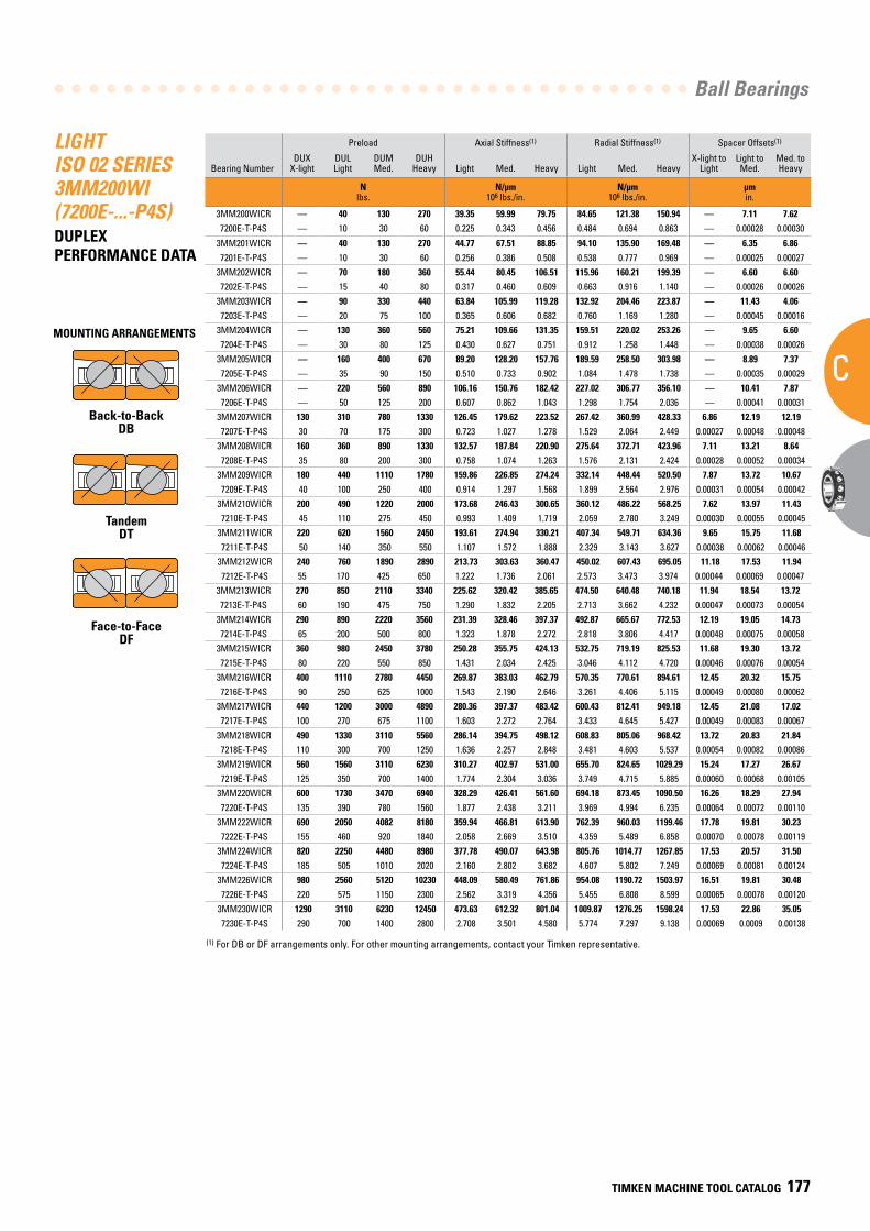
Ball Bearings
C
TIMKEN MACHINE TOOL CATALOG 177
LIGHT ISO 02 SERIES 3MM200WI (7200E-...-P4S)DUPLEX PERFORMANCE DATA
Preload Axial Stiffness(1) Radial Stiffness(1) Spacer Offsets(1)
Bearing NumberDUX
X-lightDULLight
DUMMed.
DUHHeavy Light Med. Heavy Light Med. Heavy
X-light toLight
Light toMed.
Med. toHeavy
N lbs.
N/µm 106 lbs./in.
N/µm 106 lbs./in.
µm in.
3MM200WICR — 40 130 270 39.35 59.99 79.75 84.65 121.38 150.94 — 7.11 7.627200E-T-P4S — 10 30 60 0.225 0.343 0.456 0.484 0.694 0.863 — 0.00028 0.00030
3MM201WICR — 40 130 270 44.77 67.51 88.85 94.10 135.90 169.48 — 6.35 6.867201E-T-P4S — 10 30 60 0.256 0.386 0.508 0.538 0.777 0.969 — 0.00025 0.00027
3MM202WICR — 70 180 360 55.44 80.45 106.51 115.96 160.21 199.39 — 6.60 6.607202E-T-P4S — 15 40 80 0.317 0.460 0.609 0.663 0.916 1.140 — 0.00026 0.00026
3MM203WICR — 90 330 440 63.84 105.99 119.28 132.92 204.46 223.87 — 11.43 4.067203E-T-P4S — 20 75 100 0.365 0.606 0.682 0.760 1.169 1.280 — 0.00045 0.00016
3MM204WICR — 130 360 560 75.21 109.66 131.35 159.51 220.02 253.26 — 9.65 6.607204E-T-P4S — 30 80 125 0.430 0.627 0.751 0.912 1.258 1.448 — 0.00038 0.00026
3MM205WICR — 160 400 670 89.20 128.20 157.76 189.59 258.50 303.98 — 8.89 7.377205E-T-P4S — 35 90 150 0.510 0.733 0.902 1.084 1.478 1.738 — 0.00035 0.00029
3MM206WICR — 220 560 890 106.16 150.76 182.42 227.02 306.77 356.10 — 10.41 7.877206E-T-P4S — 50 125 200 0.607 0.862 1.043 1.298 1.754 2.036 — 0.00041 0.00031
3MM207WICR 130 310 780 1330 126.45 179.62 223.52 267.42 360.99 428.33 6.86 12.19 12.197207E-T-P4S 30 70 175 300 0.723 1.027 1.278 1.529 2.064 2.449 0.00027 0.00048 0.00048
3MM208WICR 160 360 890 1330 132.57 187.84 220.90 275.64 372.71 423.96 7.11 13.21 8.647208E-T-P4S 35 80 200 300 0.758 1.074 1.263 1.576 2.131 2.424 0.00028 0.00052 0.00034
3MM209WICR 180 440 1110 1780 159.86 226.85 274.24 332.14 448.44 520.50 7.87 13.72 10.677209E-T-P4S 40 100 250 400 0.914 1.297 1.568 1.899 2.564 2.976 0.00031 0.00054 0.00042
3MM210WICR 200 490 1220 2000 173.68 246.43 300.65 360.12 486.22 568.25 7.62 13.97 11.437210E-T-P4S 45 110 275 450 0.993 1.409 1.719 2.059 2.780 3.249 0.00030 0.00055 0.00045
3MM211WICR 220 620 1560 2450 193.61 274.94 330.21 407.34 549.71 634.36 9.65 15.75 11.687211E-T-P4S 50 140 350 550 1.107 1.572 1.888 2.329 3.143 3.627 0.00038 0.00062 0.00046
3MM212WICR 240 760 1890 2890 213.73 303.63 360.47 450.02 607.43 695.05 11.18 17.53 11.947212E-T-P4S 55 170 425 650 1.222 1.736 2.061 2.573 3.473 3.974 0.00044 0.00069 0.00047
3MM213WICR 270 850 2110 3340 225.62 320.42 385.65 474.50 640.48 740.18 11.94 18.54 13.727213E-T-P4S 60 190 475 750 1.290 1.832 2.205 2.713 3.662 4.232 0.00047 0.00073 0.00054
3MM214WICR 290 890 2220 3560 231.39 328.46 397.37 492.87 665.67 772.53 12.19 19.05 14.737214E-T-P4S 65 200 500 800 1.323 1.878 2.272 2.818 3.806 4.417 0.00048 0.00075 0.00058
3MM215WICR 360 980 2450 3780 250.28 355.75 424.13 532.75 719.19 825.53 11.68 19.30 13.727215E-T-P4S 80 220 550 850 1.431 2.034 2.425 3.046 4.112 4.720 0.00046 0.00076 0.00054
3MM216WICR 400 1110 2780 4450 269.87 383.03 462.79 570.35 770.61 894.61 12.45 20.32 15.757216E-T-P4S 90 250 625 1000 1.543 2.190 2.646 3.261 4.406 5.115 0.00049 0.00080 0.00062
3MM217WICR 440 1200 3000 4890 280.36 397.37 483.42 600.43 812.41 949.18 12.45 21.08 17.027217E-T-P4S 100 270 675 1100 1.603 2.272 2.764 3.433 4.645 5.427 0.00049 0.00083 0.00067
3MM218WICR 490 1330 3110 5560 286.14 394.75 498.12 608.83 805.06 968.42 13.72 20.83 21.847218E-T-P4S 110 300 700 1250 1.636 2.257 2.848 3.481 4.603 5.537 0.00054 0.00082 0.00086
3MM219WICR 560 1560 3110 6230 310.27 402.97 531.00 655.70 824.65 1029.29 15.24 17.27 26.677219E-T-P4S 125 350 700 1400 1.774 2.304 3.036 3.749 4.715 5.885 0.00060 0.00068 0.00105
3MM220WICR 600 1730 3470 6940 328.29 426.41 561.60 694.18 873.45 1090.50 16.26 18.29 27.947220E-T-P4S 135 390 780 1560 1.877 2.438 3.211 3.969 4.994 6.235 0.00064 0.00072 0.00110
3MM222WICR 690 2050 4082 8180 359.94 466.81 613.90 762.39 960.03 1199.46 17.78 19.81 30.237222E-T-P4S 155 460 920 1840 2.058 2.669 3.510 4.359 5.489 6.858 0.00070 0.00078 0.00119
3MM224WICR 820 2250 4480 8980 377.78 490.07 643.98 805.76 1014.77 1267.85 17.53 20.57 31.507224E-T-P4S 185 505 1010 2020 2.160 2.802 3.682 4.607 5.802 7.249 0.00069 0.00081 0.00124
3MM226WICR 980 2560 5120 10230 448.09 580.49 761.86 954.08 1190.72 1503.97 16.51 19.81 30.487226E-T-P4S 220 575 1150 2300 2.562 3.319 4.356 5.455 6.808 8.599 0.00065 0.00078 0.00120
3MM230WICR 1290 3110 6230 12450 473.63 612.32 801.04 1009.87 1276.25 1598.24 17.53 22.86 35.057230E-T-P4S 290 700 1400 2800 2.708 3.501 4.580 5.774 7.297 9.138 0.00069 0.0009 0.00138
(1) For DB or DF arrangements only. For other mounting arrangements, contact your Timken representative.
MOUNTING ARRANGEMENTS
Back-to-BackDB
TandemDT
Face-to-FaceDF
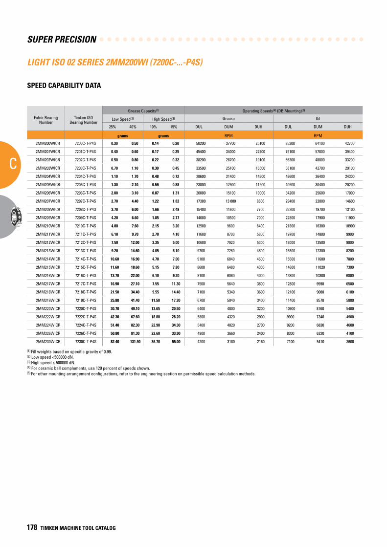
SUPER PRECISION
C
178 TIMKEN MACHINE TOOL CATALOG
LIGHT ISO 02 SERIES 2MM200WI (7200C-...-P4S)
SPEED CAPABILITY DATA
Fafnir Bearing Number
Timken ISO Bearing Number
Grease Capacity(1) Operating Speeds(4) (DB Mounting)(5)
Low Speed(2) High Speed(3) Grease Oil
25% 40% 10% 15% DUL DUM DUH DUL DUM DUH
grams grams RPM RPM
2MM200WICR 7200C-T-P4S 0.30 0.50 0.14 0.20 50200 37700 25100 85300 64100 42700
2MM201WICR 7201C-T-P4S 0.40 0.60 0.17 0.25 45400 34000 22200 79100 57800 39400
2MM202WICR 7202C-T-P4S 0.50 0.80 0.22 0.32 38200 28700 19100 66300 48800 33200
2MM203WICR 7203C-T-P4S 0.70 1.10 0.30 0.45 33500 25100 16500 58100 42700 29100
2MM204WICR 7204C-T-P4S 1.10 1.70 0.48 0.72 28600 21400 14300 48600 36400 24300
2MM205WICR 7205C-T-P4S 1.30 2.10 0.59 0.88 23800 17900 11900 40500 30400 20200
2MM206WICR 7206C-T-P4S 2.00 3.10 0.87 1.31 20000 15100 10000 34200 25600 17000
2MM207WICR 7207C-T-P4S 2.70 4.40 1.22 1.82 17300 13 000 8600 29400 22000 14600
2MM208WICR 7208C-T-P4S 3.70 6.00 1.66 2.49 15400 11600 7700 26200 19700 13100
2MM209WICR 7209C-T-P4S 4.20 6.60 1.85 2.77 14000 10500 7000 22800 17900 11900
2MM210WICR 7210C-T-P4S 4.80 7.60 2.15 3.20 12500 9600 6400 21800 16300 10900
2MM211WICR 7211C-T-P4S 6.10 9.70 2.70 4.10 11600 8700 5800 19700 14800 9900
2MM212WICR 7212C-T-P4S 7.50 12.00 3.35 5.00 10600 7920 5300 18000 13500 9000
2MM213WICR 7213C-T-P4S 9.20 14.60 4.05 6.10 9700 7260 4800 16500 12300 8200
2MM214WICR 7214C-T-P4S 10.60 16.90 4.70 7.00 9100 6840 4600 15500 11600 7800
2MM215WICR 7215C-T-P4S 11.60 18.60 5.15 7.80 8600 6480 4300 14600 11020 7300
2MM216WICR 7216C-T-P4S 13.70 22.00 6.10 9.20 8100 6060 4000 13800 10300 6800
2MM217WICR 7217C-T-P4S 16.90 27.10 7.55 11.30 7500 5640 3800 12800 9590 6500
2MM218WICR 7218C-T-P4S 21.50 34.40 9.55 14.40 7100 5340 3600 12100 9080 6100
2MM219WICR 7219C-T-P4S 25.80 41.40 11.50 17.30 6700 5040 3400 11400 8570 5800
2MM220WICR 7220C-T-P4S 30.70 49.10 13.65 20.50 6400 4800 3200 10900 8160 5400
2MM222WICR 7222C-T-P4S 42.30 67.60 18.80 28.20 5800 4320 2900 9900 7340 4900
2MM224WICR 7224C-T-P4S 51.40 82.30 22.90 34.30 5400 4020 2700 9200 6830 4600
2MM226WICR 7226C-T-P4S 50.80 81.30 22.60 33.90 4900 3660 2400 8300 6220 4100
2MM230WICR 7230C-T-P4S 82.40 131.90 36.70 55.00 4200 3180 2160 7100 5410 3600
(1) Fill weights based on specific gravity of 0.99.(2) Low speed <500000 dN.(3) High speed > 500000 dN.(4) For ceramic ball complements, use 120 percent of speeds shown.(5) For other mounting arrangement configurations, refer to the engineering section on permissible speed calculation methods.
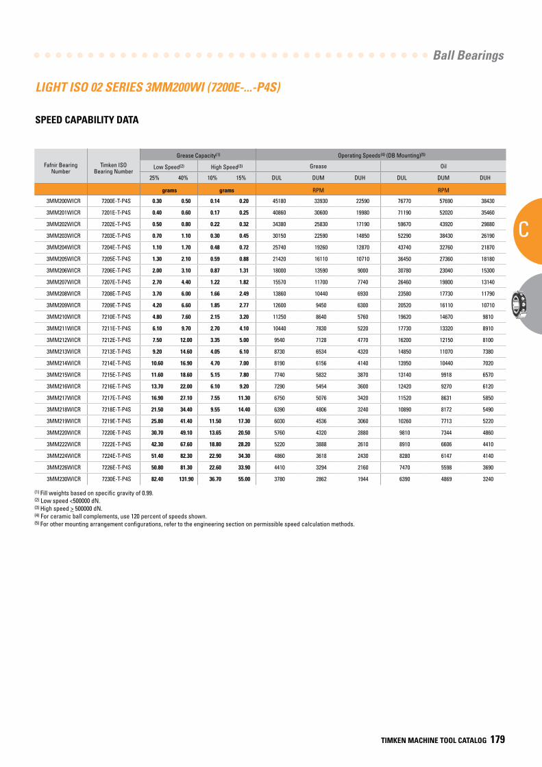
Ball Bearings
C
TIMKEN MACHINE TOOL CATALOG 179
LIGHT ISO 02 SERIES 3MM200WI (7200E-...-P4S)
SPEED CAPABILITY DATA
Fafnir Bearing Number
Timken ISO Bearing Number
Grease Capacity(1) Operating Speeds(4) (DB Mounting)(5)
Low Speed(2) High Speed(3) Grease Oil
25% 40% 10% 15% DUL DUM DUH DUL DUM DUH
grams grams RPM RPM
3MM200WICR 7200E-T-P4S 0.30 0.50 0.14 0.20 45180 33930 22590 76770 57690 38430
3MM201WICR 7201E-T-P4S 0.40 0.60 0.17 0.25 40860 30600 19980 71190 52020 35460
3MM202WICR 7202E-T-P4S 0.50 0.80 0.22 0.32 34380 25830 17190 59670 43920 29880
3MM203WICR 7203E-T-P4S 0.70 1.10 0.30 0.45 30150 22590 14850 52290 38430 26190
3MM204WICR 7204E-T-P4S 1.10 1.70 0.48 0.72 25740 19260 12870 43740 32760 21870
3MM205WICR 7205E-T-P4S 1.30 2.10 0.59 0.88 21420 16110 10710 36450 27360 18180
3MM206WICR 7206E-T-P4S 2.00 3.10 0.87 1.31 18000 13590 9000 30780 23040 15300
3MM207WICR 7207E-T-P4S 2.70 4.40 1.22 1.82 15570 11700 7740 26460 19800 13140
3MM208WICR 7208E-T-P4S 3.70 6.00 1.66 2.49 13860 10440 6930 23580 17730 11790
3MM209WICR 7209E-T-P4S 4.20 6.60 1.85 2.77 12600 9450 6300 20520 16110 10710
3MM210WICR 7210E-T-P4S 4.80 7.60 2.15 3.20 11250 8640 5760 19620 14670 9810
3MM211WICR 7211E-T-P4S 6.10 9.70 2.70 4.10 10440 7830 5220 17730 13320 8910
3MM212WICR 7212E-T-P4S 7.50 12.00 3.35 5.00 9540 7128 4770 16200 12150 8100
3MM213WICR 7213E-T-P4S 9.20 14.60 4.05 6.10 8730 6534 4320 14850 11070 7380
3MM214WICR 7214E-T-P4S 10.60 16.90 4.70 7.00 8190 6156 4140 13950 10440 7020
3MM215WICR 7215E-T-P4S 11.60 18.60 5.15 7.80 7740 5832 3870 13140 9918 6570
3MM216WICR 7216E-T-P4S 13.70 22.00 6.10 9.20 7290 5454 3600 12420 9270 6120
3MM217WICR 7217E-T-P4S 16.90 27.10 7.55 11.30 6750 5076 3420 11520 8631 5850
3MM218WICR 7218E-T-P4S 21.50 34.40 9.55 14.40 6390 4806 3240 10890 8172 5490
3MM219WICR 7219E-T-P4S 25.80 41.40 11.50 17.30 6030 4536 3060 10260 7713 5220
3MM220WICR 7220E-T-P4S 30.70 49.10 13.65 20.50 5760 4320 2880 9810 7344 4860
3MM222WICR 7222E-T-P4S 42.30 67.60 18.80 28.20 5220 3888 2610 8910 6606 4410
3MM224WICR 7224E-T-P4S 51.40 82.30 22.90 34.30 4860 3618 2430 8280 6147 4140
3MM226WICR 7226E-T-P4S 50.80 81.30 22.60 33.90 4410 3294 2160 7470 5598 3690
3MM230WICR 7230E-T-P4S 82.40 131.90 36.70 55.00 3780 2862 1944 6390 4869 3240
(1) Fill weights based on specific gravity of 0.99.(2) Low speed <500000 dN.(3) High speed > 500000 dN.(4) For ceramic ball complements, use 120 percent of speeds shown.(5) For other mounting arrangement configurations, refer to the engineering section on permissible speed calculation methods.
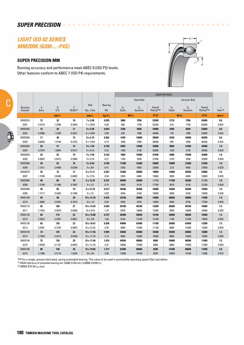
SUPER PRECISION
C
180 TIMKEN MACHINE TOOL CATALOG
C
D
r
dr
(Ng) For a single, grease-lubricated, spring-preloaded bearing. This value to be used in permissible operating speed (Sp) calculation.(1) Width tolerance of preloaded bearing set +0.000/-0.254 mm (+0.0000/-0.0100 in.).(2) ABMA STD 20 (ras max).
LIGHT ISO 02 SERIES MM200K (6200-...-P4S)
SUPER PRECISION MM
Running accuracy and performance meet ABEC 9 (ISO P2) levels. Other features conform to ABEC 7 (ISO P4) requirements.
BearingNumber
dBore
DO.D.
CWidth(1)
Ball Bearing
LOAD RATINGS
rRad.(2)
Suggested Shoulder Diameters Shaft Diameter Mounting Fits
FIXED FLOATING
Steel Ball Ceramic Ball Housing Bore (Stationary) Mounting Fits Housing Bore
(Stationary) Mounting Fits
CoStatic
CeDynamic
SpeedRating(Ng)
CoStatic
CeDynamic
SpeedRating(Ng)
Shaft Housing
Qty. x Dia. Wt. Max. Min. Max. Min. Max. Min. Loose Tight Max. Min. Tight Loose Max. Min. Loose Loose
mm/in. mm/in. kg/lbs. N/lbs. RPM N/lbs. RPM mm/in. mm/in. mm/in. mm/in. mm/in. mm/in. mm/in. mm/in. mm/in.
MM201K 12 32 10 7 x 5.95 0.035 3000 7550 52200 2710 7550 62600 0.6 16.6 16.4 28.1 27.8 12.000 11.995 0.005 0.004 32.005 32.000 0.000 0.011 32.010 32.005 0.016 0.005
6201 0.4724 1.2598 0.3940 7 x 15/64 0.08 680 1700 52200 610 1700 62600 0.024 0.66 0.65 1.11 1.10 0.47240 0.47220 0.00020 0.00015 1.26000 1.25980 0.00000 0.00045 1.26020 1.26000 0.00070 0.00020
MM202K 15 35 11 8 x 5.95 0.043 3700 8450 44000 3290 8450 52800 0.6 19.2 18.9 31.1 30.9 15.000 14.995 0.005 0.004 35.006 35.000 0.000 0.012 35.010 35.005 0.016 0.005
6202 0.5906 1.3780 0.4331 8 x 15/64 0.09 830 1900 44000 740 1900 52800 0.024 0.76 0.75 1.23 1.22 0.59060 0.59040 0.00020 0.00015 1.37830 1.37800 0.00000 0.00050 1.37840 1.37820 0.00070 0.00020
MM203K 17 40 12 8 x 6.75 0.062 4700 10600 38500 4230 10600 46200 0.6 21.7 21.5 35.7 35.4 17.000 16.995 0.005 0.004 40.006 40.000 0.000 0.012 40.010 40.005 0.016 0.005
6203 0.6693 1.5748 0.4724 8 x 17/64 0.14 1060 2380 38500 950 2380 46200 0.024 0.86 0.85 1.41 1.40 0.66930 0.66910 0.00020 0.00015 1.57510 1.57480 0.00000 0.00050 1.57520 1.57500 0.00070 0.00020
MM204K 20 47 14 8 x 7.94 0.100 6500 14200 32800 5860 14200 39400 1.0 26.0 25.8 41.5 41.3 20.000 19.995 0.005 0.005 47.006 47.000 0.000 0.012 47.012 47.007 0.018 0.007
6204 0.7874 1.8504 0.5512 8 x 5/16 0.22 1460 3190 32800 1320 3190 39400 0.039 1.03 1.02 1.64 1.63 0.78740 0.78720 0.00020 0.00020 1.85070 1.85040 0.00000 0.00050 1.85090 1.85070 0.00080 0.00030
MM205K 25 52 15 9 x 7.94 0.122 7800 15500 27400 6980 15500 32900 1.0 31.1 30.9 47.1 46.9 25.000 24.995 0.005 0.005 52.006 52.000 0.000 0.013 52.012 52.007 0.019 0.007
6205 0.9843 2.0472 0.5906 9 x 5/16 0.27 1760 3490 27400 1570 3490 32900 0.039 1.23 1.22 1.86 1.85 0.98430 0.98410 0.00020 0.00020 2.04750 2.04720 0.00000 0.00055 2.04770 2.04750 0.00080 0.00030
MM206K 30 62 16 9 x 9.53 0.185 11300 21600 23000 10000 21600 27600 1.0 36.7 36.5 56.0 55.8 30.000 29.995 0.005 0.005 62.008 62.000 0.000 0.015 62.012 62.007 0.019 0.007
6206 1.1811 2.4409 0.6299 9 x 3/8 0.41 2550 4850 23000 2.25 4850 27600 0.039 1.45 1.44 2.21 2.20 1.18110 1.18090 0.00020 0.00020 2.44120 2.44090 0.00000 0.00060 2.44140 2.44120 0.00080 0.00030
MM207K 35 72 17 9 x 11.11 0.267 15300 28500 19800 13600 28500 23800 1.0 42.7 42.2 65.3 64.8 35.000 34.995 0.005 0.006 72.008 72.000 0.000 0.015 72.011 72.007 0.019 0.007
6207 1.3780 2.8346 0.6693 9 x 7/16 0.59 3450 6400 19800 3060 6400 23800 0.039 1.68 1.66 2.57 2.55 1.37800 1.37780 0.00020 0.00025 2.83490 2.83460 0.00000 0.00060 2.83510 2.83490 0.00080 0.00030
MM208K 40 80 18 9 x 12.70 0.337 20000 36200 17700 17700 36200 21200 1.0 47.8 47.2 73.2 72.6 40.000 39.995 0.005 0.006 80.008 80.000 0.000 0.015 80.012 80.008 0.020 0.008
6208 1.5748 3.1496 0.7087 9 x 1/2 0.74 4500 8130 17700 3970 8130 21200 0.039 1.88 1.86 2.88 2.86 1.57480 1.57460 0.00020 0.00025 3.14990 3.14960 0.00000 0.00060 3.15010 3.14990 0.00080 0.00030
MM209K 45 85 19 9 x 12.70 0.377 20200 36300 16000 18200 36300 19200 1.0 52.8 52.3 78.2 77.7 45.000 44.995 0.005 0.006 85.008 85.000 0.000 0.016 85.016 85.009 0.024 0.009
6209 1.7717 3.3465 0.7480 9 x 1/2 0.83 4550 8160 16000 4090 8160 19200 0.039 2.08 2.06 3.08 3.06 1.77170 1.77150 0.00020 0.00025 3.34680 3.34650 0.00000 0.00060 3.34710 3.34680 0.00090 0.00030
MM210K 50 90 20 10 x 12.70 0.425 23100 38900 14600 20600 38900 17500 1.0 57.9 57.4 83.3 82.8 50.000 49.995 0.005 0.006 90.008 90.000 0.000 0.016 90.015 90.007 0.023 0.007
6210 1.9685 3.5433 0.7874 10 x 1/2 0.94 5200 8740 14600 4640 8740 17500 0.039 2.28 2.26 3.28 3.26 1.96850 1.96830 0.00020 0.00025 3.54360 3.54330 0.00000 0.00060 3.54390 3.54360 0.00090 0.00030
MM211K 55 100 21 10 x 14.29 0.564 29100 48100 13300 26000 48100 16000 1.5 63.8 63.3 92.2 91.7 55.000 54.995 0.005 0.007 100.008 100.000 0.000 0.016 100.018 100.010 0.025 0.010
6211 2.1654 3.9370 0.8268 10 x 9/16 1.24 6550 10800 13300 5850 10800 16000 0.059 2.51 2.49 3.63 3.61 2.16540 2.16520 0.00020 0.00030 3.93730 3.93700 0.00000 0.00060 3.93770 3.93740 0.00100 0.00040
MM212K 60 110 22 10 x 15.88 0.727 36300 58200 12100 32000 58200 14500 1.5 69.9 69.3 101.4 100.8 60.000 59.995 0.005 0.007 110.008 110.000 0.000 0.016 110.018 110.010 0.025 0.010
6212 2.3622 4.3307 0.8661 10 x 5/8 1.60 8150 13100 12100 7190 13100 14500 0.059 2.75 2.73 3.99 3.97 2.36220 2.36200 0.00020 0.00030 4.33100 4.33070 0.00000 0.00060 4.33140 4.33110 0.00100 0.00040
MM213K 65 120 23 10 x 16.67 0.928 40000 63400 11100 35600 63400 13300 1.5 76.2 75.7 109.7 109.2 65.000 64.995 0.005 0.007 120.008 120.000 0.000 0.016 120.018 120.010 0.025 0.010
6213 2.5591 4.7244 0.9055 10 x 21/32 2.05 9000 14300 11100 8000 14300 13300 0.059 3.00 2.98 4.32 4.30 2.55910 2.55890 0.00020 0.00030 4.72470 4.72440 0.00000 0.00060 4.72510 4.72480 0.00100 0.00040
MM214K 70 125 24 10 x 17.46 0.994 43600 69000 10500 39200 69000 12600 1.5 80.8 80.3 115.8 115.3 70.000 69.995 0.005 0.007 125.008 125.000 0.000 0.017 125.021 125.011 0.030 0.011
6214 2.7559 4.9213 0.9449 10 x 11/16 2.19 9800 15500 10500 8800 15500 12600 0.059 3.18 3.16 4.56 4.54 2.75590 2.75570 0.00020 0.00030 4.92160 4.92130 0.00000 0.00070 4.92210 4.92170 0.00120 0.00040
MM215K 75 130 25 10 x 17.46 1.074 44500 68900 9900 39900 68900 11900 1.5 86.0 85.2 120.8 120.0 75.005 74.995 0.005 0.012 130.009 130.000 0.000 0.018 130.020 130.010 0.029 0.010
6215 2.9528 5.1181 0.9843 10 x 11/16 2.37 10000 15500 9900 8960 15500 11900 0.059 3.39 3.36 4.76 4.73 2.95300 2.95260 0.00020 0.00050 5.11850 5.11810 0.00000 0.00070 5.11890 5.11850 0.00110 0.00040
MM216K 80 140 26 10 x 19.05 1.317 53400 80600 9200 47200 80600 11000 2.0 91.3 90.6 129.9 129.2 80.005 79.995 0.005 0.012 140.009 140.000 0.000 0.018 140.020 140.010 0.029 0.010
6216 3.1496 5.5118 1.0236 10 x 3/4 2.90 12000 18100 9200 10600 18100 11000 0.079 3.60 3.57 5.12 5.09 3.14980 3.14940 0.00020 0.00050 5.51220 5.51180 0.00000 0.00070 5.51260 5.51220 0.00110 0.00040
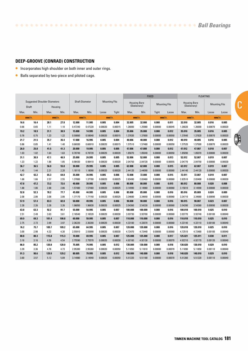
Ball Bearings
C
TIMKEN MACHINE TOOL CATALOG 181
DEEP-GROOVE (CONRAD) CONSTRUCTION
• Incorporates high shoulder on both inner and outer rings.
• Balls separated by two-piece and piloted cage.
BearingNumber
dBore
DO.D.
CWidth(1)
Ball Bearing
LOAD RATINGS
rRad.(2)
Suggested Shoulder Diameters Shaft Diameter Mounting Fits
FIXED FLOATING
Steel Ball Ceramic Ball Housing Bore (Stationary) Mounting Fits Housing Bore
(Stationary) Mounting Fits
CoStatic
CeDynamic
SpeedRating(Ng)
CoStatic
CeDynamic
SpeedRating(Ng)
Shaft Housing
Qty. x Dia. Wt. Max. Min. Max. Min. Max. Min. Loose Tight Max. Min. Tight Loose Max. Min. Loose Loose
mm/in. mm/in. kg/lbs. N/lbs. RPM N/lbs. RPM mm/in. mm/in. mm/in. mm/in. mm/in. mm/in. mm/in. mm/in. mm/in.
MM201K 12 32 10 7 x 5.95 0.035 3000 7550 52200 2710 7550 62600 0.6 16.6 16.4 28.1 27.8 12.000 11.995 0.005 0.004 32.005 32.000 0.000 0.011 32.010 32.005 0.016 0.005
6201 0.4724 1.2598 0.3940 7 x 15/64 0.08 680 1700 52200 610 1700 62600 0.024 0.66 0.65 1.11 1.10 0.47240 0.47220 0.00020 0.00015 1.26000 1.25980 0.00000 0.00045 1.26020 1.26000 0.00070 0.00020
MM202K 15 35 11 8 x 5.95 0.043 3700 8450 44000 3290 8450 52800 0.6 19.2 18.9 31.1 30.9 15.000 14.995 0.005 0.004 35.006 35.000 0.000 0.012 35.010 35.005 0.016 0.005
6202 0.5906 1.3780 0.4331 8 x 15/64 0.09 830 1900 44000 740 1900 52800 0.024 0.76 0.75 1.23 1.22 0.59060 0.59040 0.00020 0.00015 1.37830 1.37800 0.00000 0.00050 1.37840 1.37820 0.00070 0.00020
MM203K 17 40 12 8 x 6.75 0.062 4700 10600 38500 4230 10600 46200 0.6 21.7 21.5 35.7 35.4 17.000 16.995 0.005 0.004 40.006 40.000 0.000 0.012 40.010 40.005 0.016 0.005
6203 0.6693 1.5748 0.4724 8 x 17/64 0.14 1060 2380 38500 950 2380 46200 0.024 0.86 0.85 1.41 1.40 0.66930 0.66910 0.00020 0.00015 1.57510 1.57480 0.00000 0.00050 1.57520 1.57500 0.00070 0.00020
MM204K 20 47 14 8 x 7.94 0.100 6500 14200 32800 5860 14200 39400 1.0 26.0 25.8 41.5 41.3 20.000 19.995 0.005 0.005 47.006 47.000 0.000 0.012 47.012 47.007 0.018 0.007
6204 0.7874 1.8504 0.5512 8 x 5/16 0.22 1460 3190 32800 1320 3190 39400 0.039 1.03 1.02 1.64 1.63 0.78740 0.78720 0.00020 0.00020 1.85070 1.85040 0.00000 0.00050 1.85090 1.85070 0.00080 0.00030
MM205K 25 52 15 9 x 7.94 0.122 7800 15500 27400 6980 15500 32900 1.0 31.1 30.9 47.1 46.9 25.000 24.995 0.005 0.005 52.006 52.000 0.000 0.013 52.012 52.007 0.019 0.007
6205 0.9843 2.0472 0.5906 9 x 5/16 0.27 1760 3490 27400 1570 3490 32900 0.039 1.23 1.22 1.86 1.85 0.98430 0.98410 0.00020 0.00020 2.04750 2.04720 0.00000 0.00055 2.04770 2.04750 0.00080 0.00030
MM206K 30 62 16 9 x 9.53 0.185 11300 21600 23000 10000 21600 27600 1.0 36.7 36.5 56.0 55.8 30.000 29.995 0.005 0.005 62.008 62.000 0.000 0.015 62.012 62.007 0.019 0.007
6206 1.1811 2.4409 0.6299 9 x 3/8 0.41 2550 4850 23000 2.25 4850 27600 0.039 1.45 1.44 2.21 2.20 1.18110 1.18090 0.00020 0.00020 2.44120 2.44090 0.00000 0.00060 2.44140 2.44120 0.00080 0.00030
MM207K 35 72 17 9 x 11.11 0.267 15300 28500 19800 13600 28500 23800 1.0 42.7 42.2 65.3 64.8 35.000 34.995 0.005 0.006 72.008 72.000 0.000 0.015 72.011 72.007 0.019 0.007
6207 1.3780 2.8346 0.6693 9 x 7/16 0.59 3450 6400 19800 3060 6400 23800 0.039 1.68 1.66 2.57 2.55 1.37800 1.37780 0.00020 0.00025 2.83490 2.83460 0.00000 0.00060 2.83510 2.83490 0.00080 0.00030
MM208K 40 80 18 9 x 12.70 0.337 20000 36200 17700 17700 36200 21200 1.0 47.8 47.2 73.2 72.6 40.000 39.995 0.005 0.006 80.008 80.000 0.000 0.015 80.012 80.008 0.020 0.008
6208 1.5748 3.1496 0.7087 9 x 1/2 0.74 4500 8130 17700 3970 8130 21200 0.039 1.88 1.86 2.88 2.86 1.57480 1.57460 0.00020 0.00025 3.14990 3.14960 0.00000 0.00060 3.15010 3.14990 0.00080 0.00030
MM209K 45 85 19 9 x 12.70 0.377 20200 36300 16000 18200 36300 19200 1.0 52.8 52.3 78.2 77.7 45.000 44.995 0.005 0.006 85.008 85.000 0.000 0.016 85.016 85.009 0.024 0.009
6209 1.7717 3.3465 0.7480 9 x 1/2 0.83 4550 8160 16000 4090 8160 19200 0.039 2.08 2.06 3.08 3.06 1.77170 1.77150 0.00020 0.00025 3.34680 3.34650 0.00000 0.00060 3.34710 3.34680 0.00090 0.00030
MM210K 50 90 20 10 x 12.70 0.425 23100 38900 14600 20600 38900 17500 1.0 57.9 57.4 83.3 82.8 50.000 49.995 0.005 0.006 90.008 90.000 0.000 0.016 90.015 90.007 0.023 0.007
6210 1.9685 3.5433 0.7874 10 x 1/2 0.94 5200 8740 14600 4640 8740 17500 0.039 2.28 2.26 3.28 3.26 1.96850 1.96830 0.00020 0.00025 3.54360 3.54330 0.00000 0.00060 3.54390 3.54360 0.00090 0.00030
MM211K 55 100 21 10 x 14.29 0.564 29100 48100 13300 26000 48100 16000 1.5 63.8 63.3 92.2 91.7 55.000 54.995 0.005 0.007 100.008 100.000 0.000 0.016 100.018 100.010 0.025 0.010
6211 2.1654 3.9370 0.8268 10 x 9/16 1.24 6550 10800 13300 5850 10800 16000 0.059 2.51 2.49 3.63 3.61 2.16540 2.16520 0.00020 0.00030 3.93730 3.93700 0.00000 0.00060 3.93770 3.93740 0.00100 0.00040
MM212K 60 110 22 10 x 15.88 0.727 36300 58200 12100 32000 58200 14500 1.5 69.9 69.3 101.4 100.8 60.000 59.995 0.005 0.007 110.008 110.000 0.000 0.016 110.018 110.010 0.025 0.010
6212 2.3622 4.3307 0.8661 10 x 5/8 1.60 8150 13100 12100 7190 13100 14500 0.059 2.75 2.73 3.99 3.97 2.36220 2.36200 0.00020 0.00030 4.33100 4.33070 0.00000 0.00060 4.33140 4.33110 0.00100 0.00040
MM213K 65 120 23 10 x 16.67 0.928 40000 63400 11100 35600 63400 13300 1.5 76.2 75.7 109.7 109.2 65.000 64.995 0.005 0.007 120.008 120.000 0.000 0.016 120.018 120.010 0.025 0.010
6213 2.5591 4.7244 0.9055 10 x 21/32 2.05 9000 14300 11100 8000 14300 13300 0.059 3.00 2.98 4.32 4.30 2.55910 2.55890 0.00020 0.00030 4.72470 4.72440 0.00000 0.00060 4.72510 4.72480 0.00100 0.00040
MM214K 70 125 24 10 x 17.46 0.994 43600 69000 10500 39200 69000 12600 1.5 80.8 80.3 115.8 115.3 70.000 69.995 0.005 0.007 125.008 125.000 0.000 0.017 125.021 125.011 0.030 0.011
6214 2.7559 4.9213 0.9449 10 x 11/16 2.19 9800 15500 10500 8800 15500 12600 0.059 3.18 3.16 4.56 4.54 2.75590 2.75570 0.00020 0.00030 4.92160 4.92130 0.00000 0.00070 4.92210 4.92170 0.00120 0.00040
MM215K 75 130 25 10 x 17.46 1.074 44500 68900 9900 39900 68900 11900 1.5 86.0 85.2 120.8 120.0 75.005 74.995 0.005 0.012 130.009 130.000 0.000 0.018 130.020 130.010 0.029 0.010
6215 2.9528 5.1181 0.9843 10 x 11/16 2.37 10000 15500 9900 8960 15500 11900 0.059 3.39 3.36 4.76 4.73 2.95300 2.95260 0.00020 0.00050 5.11850 5.11810 0.00000 0.00070 5.11890 5.11850 0.00110 0.00040
MM216K 80 140 26 10 x 19.05 1.317 53400 80600 9200 47200 80600 11000 2.0 91.3 90.6 129.9 129.2 80.005 79.995 0.005 0.012 140.009 140.000 0.000 0.018 140.020 140.010 0.029 0.010
6216 3.1496 5.5118 1.0236 10 x 3/4 2.90 12000 18100 9200 10600 18100 11000 0.079 3.60 3.57 5.12 5.09 3.14980 3.14940 0.00020 0.00050 5.51220 5.51180 0.00000 0.00070 5.51260 5.51220 0.00110 0.00040
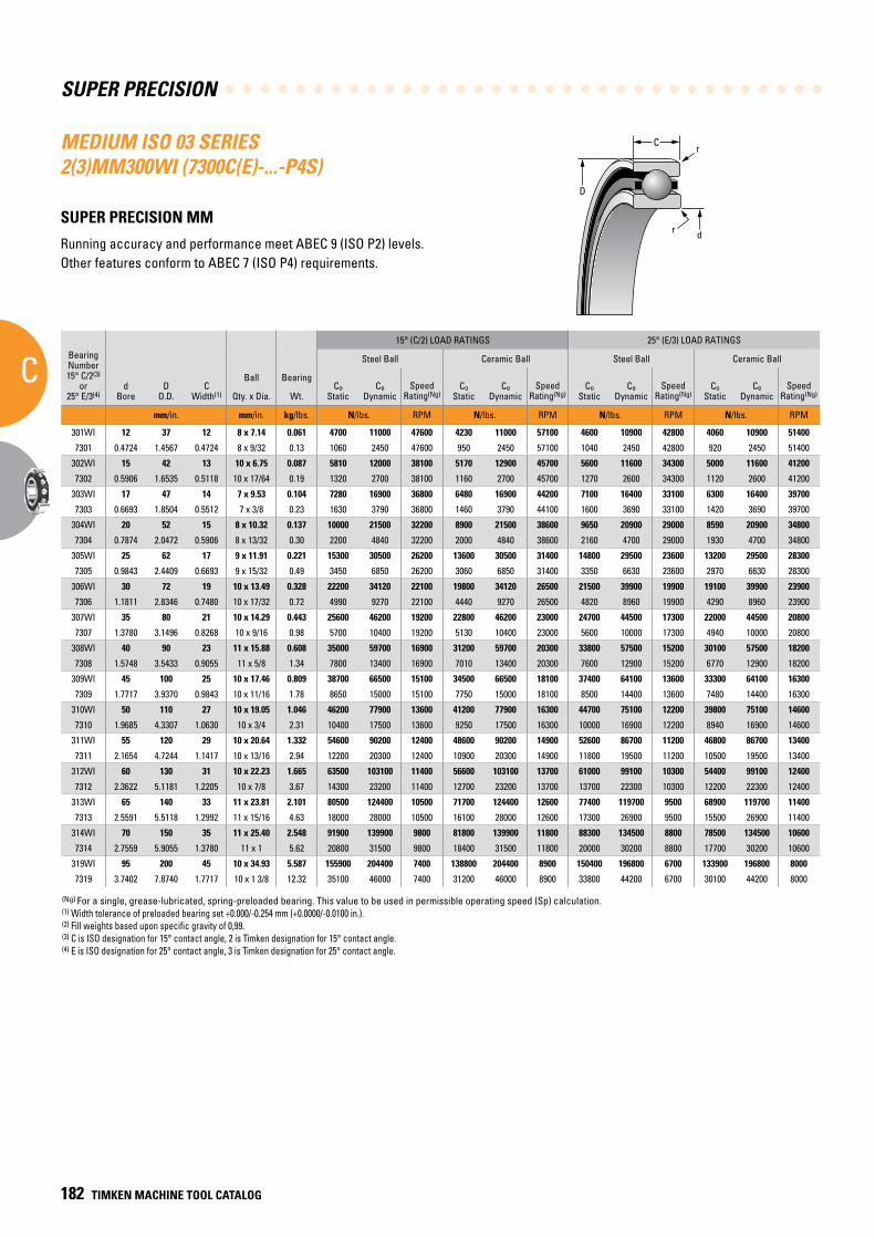
SUPER PRECISION
C
182 TIMKEN MACHINE TOOL CATALOG
C
D
r
dr
(Ng) For a single, grease-lubricated, spring-preloaded bearing. This value to be used in permissible operating speed (Sp) calculation.(1) Width tolerance of preloaded bearing set +0.000/-0.254 mm (+0.0000/-0.0100 in.).(2) Fill weights based upon specific gravity of 0,99.(3) C is ISO designation for 15° contact angle, 2 is Timken designation for 15° contact angle.(4) E is ISO designation for 25° contact angle, 3 is Timken designation for 25° contact angle.
MEDIUM ISO 03 SERIES 2(3)MM300WI (7300C(E)-...-P4S)
SUPER PRECISION MM
Running accuracy and performance meet ABEC 9 (ISO P2) levels. Other features conform to ABEC 7 (ISO P4) requirements.
BearingNumber15° C/2(3)
or25° E/3(4)
dBore
DO.D.
CWidth(1)
Ball Bearing
15° (C/2) LOAD RATINGS 25° (E/3) LOAD RATINGS
rRad.(2)
Suggested Shoulder Diameters Shaft Diameter Mounting Fits
FIXED FLOATING
Steel Ball Ceramic Ball Steel Ball Ceramic Ball Housing Bore (Stationary) Mounting Fits Housing Bore
(Stationary) Mounting Fits
CoStatic
CeDynamic
SpeedRating(Ng)
CoStatic
CeDynamic
SpeedRating(Ng)
CoStatic
CeDynamic
SpeedRating(Ng)
CoStatic
CeDynamic
SpeedRating(Ng)
Shaft Housing
Qty. x Dia. Wt. Max. Min. Max. Min. Max. Min. Loose Tight Max. Min. Tight Loose Max. Min. Loose Loose
mm/in. mm/in. kg/lbs. N/lbs. RPM N/lbs. RPM N/lbs. RPM N/lbs. RPM mm/in. mm/in. mm/in. mm/in. mm/in. mm/in. mm/in. mm/in. mm/in.
301WI 12 37 12 8 x 7.14 0.061 4700 11000 47600 4230 11000 57100 4600 10900 42800 4060 10900 51400 1.0 17.7 17.4 32.1 31.9 12.000 11.995 0.005 0.004 37.006 37.000 0.000 0.012 37.010 37.005 0.016 0.005
7301 0.4724 1.4567 0.4724 8 x 9/32 0.13 1060 2450 47600 950 2450 57100 1040 2450 42800 920 2450 51400 0.039 0.70 0.69 1.27 1.26 0.47240 0.47220 0.00020 0.00015 1.45700 1.45670 0.00000 0.00050 1.45710 1.45690 0.00070 0.00020
302WI 15 42 13 10 x 6.75 0.087 5810 12000 38100 5170 12900 45700 5600 11600 34300 5000 11600 41200 1.0 22.2 22.0 35.7 35.4 15.000 14.995 0.005 0.004 42.006 42.000 0.000 0.012 42.010 42.005 0.016 0.005
7302 0.5906 1.6535 0.5118 10 x 17/64 0.19 1320 2700 38100 1160 2700 45700 1270 2600 34300 1120 2600 41200 0.039 0.88 0.87 1.41 1.40 0.59060 0.59040 0.00020 0.00015 1.65380 1.65350 0.00000 0.00050 1.65390 1.65370 0.00070 0.00020
303WI 17 47 14 7 x 9.53 0.104 7280 16900 36800 6480 16900 44200 7100 16400 33100 6300 16400 39700 1.0 22.7 22.5 42.0 41.8 17.000 16.995 0.005 0.004 47.006 47.000 0.000 0.012 47.012 47.007 0.018 0.007
7303 0.6693 1.8504 0.5512 7 x 3/8 0.23 1630 3790 36800 1460 3790 44100 1600 3690 33100 1420 3690 39700 0.039 0.90 0.89 1.66 1.65 0.66930 0.66910 0.00020 0.00015 1.85070 1.85040 0.00000 0.00050 1.85090 1.85070 0.00080 0.00030
304WI 20 52 15 8 x 10.32 0.137 10000 21500 32200 8900 21500 38600 9650 20900 29000 8590 20900 34800 1.0 30.1 29.9 46.6 46.4 20.000 19.995 0.005 0.005 52.006 52.000 0.000 0.013 52.012 52.007 0.019 0.007
7304 0.7874 2.0472 0.5906 8 x 13/32 0.30 2200 4840 32200 2000 4840 38600 2160 4700 29000 1930 4700 34800 0.039 1.19 1.18 1.84 1.83 0.78740 0.78720 0.00020 0.00020 2.04750 2.04720 0.00000 0.00055 2.04770 2.04750 0.00080 0.00030
305WI 25 62 17 9 x 11.91 0.221 15300 30500 26200 13600 30500 31400 14800 29500 23600 13200 29500 28300 1.0 32.1 31.9 55.8 55.5 25.000 24.995 0.005 0.005 62.008 62.000 0.000 0.015 62.012 62.007 0.019 0.007
7305 0.9843 2.4409 0.6693 9 x 15/32 0.49 3450 6850 26200 3060 6850 31400 3350 6630 23600 2970 6630 28300 0.039 1.27 1.26 2.20 2.19 0.98430 0.98410 0.00020 0.00020 2.44120 2.44090 0.00000 0.00060 2.44140 2.44120 0.00080 0.00030
306WI 30 72 19 10 x 13.49 0.328 22200 34120 22100 19800 34120 26500 21500 39900 19900 19100 39900 23900 1.0 37.7 37.5 65.2 64.9 30.000 29.995 0.005 0.005 72.008 72.000 0.000 0.015 72.011 72.007 0.019 0.007
7306 1.1811 2.8346 0.7480 10 x 17/32 0.72 4990 9270 22100 4440 9270 26500 4820 8960 19900 4290 8960 23900 0.039 1.49 1.48 2.57 2.56 1.18110 1.18090 0.00020 0.00020 2.83490 2.83460 0.00000 0.00060 2.83510 2.83490 0.00080 0.00030
307WI 35 80 21 10 x 14.29 0.443 25600 46200 19200 22800 46200 23000 24700 44500 17300 22000 44500 20800 1.5 43.7 43.2 72.1 71.6 35.000 34.995 0.005 0.006 80.008 80.000 0.000 0.015 80.012 80.008 0.020 0.008
7307 1.3780 3.1496 0.8268 10 x 9/16 0.98 5700 10400 19200 5130 10400 23000 5600 10000 17300 4940 10000 20800 0.059 1.72 1.70 2.84 2.82 1.37800 1.37780 0.00020 0.00025 3.14990 3.14960 0.00000 0.00060 3.15010 3.14990 0.00080 0.00030
308WI 40 90 23 11 x 15.88 0.608 35000 59700 16900 31200 59700 20300 33800 57500 15200 30100 57500 18200 1.5 49.8 49.3 81.3 80.8 40.000 39.995 0.005 0.006 90.008 90.000 0.000 0.016 90.015 90.007 0.023 0.007
7308 1.5748 3.5433 0.9055 11 x 5/8 1.34 7800 13400 16900 7010 13400 20300 7600 12900 15200 6770 12900 18200 0.059 1.96 1.94 3.20 3.18 1.57480 1.57460 0.00020 0.00025 3.54360 3.54330 0.00000 0.00060 3.54390 3.54360 0.00090 0.00030
309WI 45 100 25 10 x 17.46 0.809 38700 66500 15100 34500 66500 18100 37400 64100 13600 33300 64100 16300 1.5 55.9 55.4 90.2 89.7 45.000 44.995 0.005 0.006 100.008 100.000 0.000 0.016 100.018 100.010 0.025 0.010
7309 1.7717 3.9370 0.9843 10 x 11/16 1.78 8650 15000 15100 7750 15000 18100 8500 14400 13600 7480 14400 16300 0.059 2.20 2.18 3.55 3.53 1.77170 1.77150 0.00020 0.00025 3.93730 3.93700 0.00000 0.00060 3.93770 3.93740 0.00100 0.00040
310WI 50 110 27 10 x 19.05 1.046 46200 77900 13600 41200 77900 16300 44700 75100 12200 39800 75100 14600 2.0 61.2 60.7 99.8 99.3 50.000 49.995 0.005 0.006 110.008 110.000 0.000 0.016 110.018 110.010 0.025 0.010
7310 1.9685 4.3307 1.0630 10 x 3/4 2.31 10400 17500 13600 9250 17500 16300 10000 16900 12200 8940 16900 14600 0.079 2.41 2.39 3.93 3.91 1.96850 1.96830 0.00020 0.00025 4.33100 4.33070 0.00000 0.00060 4.33140 4.33110 0.00100 0.00040
311WI 55 120 29 10 x 20.64 1.332 54600 90200 12400 48600 90200 14900 52600 86700 11200 46800 86700 13400 2.0 67.3 66.8 108.7 108.2 55.000 54.995 0.005 0.007 120.008 120.000 0.000 0.016 120.018 120.010 0.025 0.010
7311 2.1654 4.7244 1.1417 10 x 13/16 2.94 12200 20300 12400 10900 20300 14900 11800 19500 11200 10500 19500 13400 0.079 2.65 2.63 4.28 4.26 2.16540 2.16520 0.00020 0.00030 4.72470 4.72440 0.00000 0.00060 4.72510 4.72480 0.00100 0.00040
312WI 60 130 31 10 x 22.23 1.665 63500 103100 11400 56600 103100 13700 61000 99100 10300 54400 99100 12400 2.0 73.1 72.6 117.9 117.3 60.000 59.995 0.005 0.007 130.009 130.000 0.000 0.018 130.020 130.010 0.029 0.010
7312 2.3622 5.1181 1.2205 10 x 7/8 3.67 14300 23200 11400 12700 23200 13700 13700 22300 10300 12200 22300 12400 0.079 2.88 2.86 4.64 4.62 2.36220 2.36200 0.00020 0.00030 5.11850 5.11810 0.00000 0.00070 5.11890 5.11850 0.00110 0.00040
313WI 65 140 33 11 x 23.81 2.101 80500 124400 10500 71700 124400 12600 77400 119700 9500 68900 119700 11400 2.0 80.3 79.8 126.8 126.2 65.000 64.995 0.005 0.007 140.009 140.000 0.000 0.018 140.020 140.010 0.029 0.010
7313 2.5591 5.5118 1.2992 11 x 15/16 4.63 18000 28000 10500 16100 28000 12600 17300 26900 9500 15500 26900 11400 0.079 3.16 3.14 4.99 4.97 2.55910 2.55890 0.00020 0.00030 5.51220 5.51180 0.00000 0.00070 5.51260 5.51220 0.00110 0.00040
314WI 70 150 35 11 x 25.40 2.548 91900 139900 9800 81800 139900 11800 88300 134500 8800 78500 134500 10600 2.0 85.3 84.8 135.6 135.1 70.000 69.995 0.005 0.007 150.009 150.000 0.000 0.018 150.023 150.012 0.032 0.012
7314 2.7559 5.9055 1.3780 11 x 1 5.62 20800 31500 9800 18400 31500 11800 20000 30200 8800 17700 30200 10600 0.079 3.36 3.34 5.34 5.32 2.75590 2.75570 0.00020 0.00030 5.90590 5.90550 0.000 0.00070 5.90640 5.90600 0.00120 0.00050
319WI 95 200 45 10 x 34.93 5.587 155900 204400 7400 138800 204400 8900 150400 196800 6700 133900 196800 8000 3.0 113.2 112.4 183.3 182.5 95.000 94.995 0.005 0.013 200.011 200.000 0.000 0.022 200.025 200.015 0.036 0.015
7319 3.7402 7.8740 1.7717 10 x 1 3/8 12.32 35100 46000 7400 31200 46000 8900 33800 44200 6700 30100 44200 8000 0.118 4.46 4.43 7.22 7.19 3.74016 3.73996 0.00020 0.00051 7.87402 7.87445 0.00000 0.00087 7.87500 7.87461 0.00142 0.00059
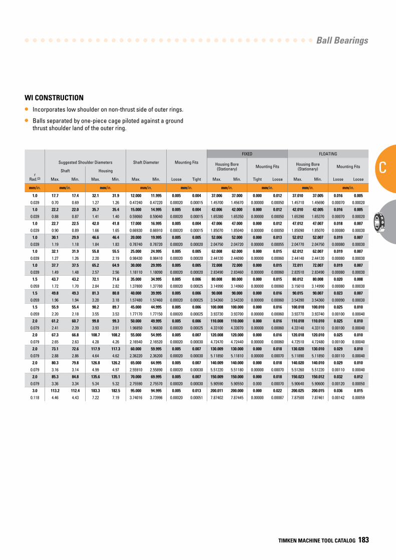
Ball Bearings
C
TIMKEN MACHINE TOOL CATALOG 183
WI CONSTRUCTION
• Incorporates low shoulder on non-thrust side of outer rings.
• Balls separated by one-piece cage piloted against a ground thrust shoulder land of the outer ring.
BearingNumber15° C/2(3)
or25° E/3(4)
dBore
DO.D.
CWidth(1)
Ball Bearing
15° (C/2) LOAD RATINGS 25° (E/3) LOAD RATINGS
rRad.(2)
Suggested Shoulder Diameters Shaft Diameter Mounting Fits
FIXED FLOATING
Steel Ball Ceramic Ball Steel Ball Ceramic Ball Housing Bore (Stationary) Mounting Fits Housing Bore
(Stationary) Mounting Fits
CoStatic
CeDynamic
SpeedRating(Ng)
CoStatic
CeDynamic
SpeedRating(Ng)
CoStatic
CeDynamic
SpeedRating(Ng)
CoStatic
CeDynamic
SpeedRating(Ng)
Shaft Housing
Qty. x Dia. Wt. Max. Min. Max. Min. Max. Min. Loose Tight Max. Min. Tight Loose Max. Min. Loose Loose
mm/in. mm/in. kg/lbs. N/lbs. RPM N/lbs. RPM N/lbs. RPM N/lbs. RPM mm/in. mm/in. mm/in. mm/in. mm/in. mm/in. mm/in. mm/in. mm/in.
301WI 12 37 12 8 x 7.14 0.061 4700 11000 47600 4230 11000 57100 4600 10900 42800 4060 10900 51400 1.0 17.7 17.4 32.1 31.9 12.000 11.995 0.005 0.004 37.006 37.000 0.000 0.012 37.010 37.005 0.016 0.005
7301 0.4724 1.4567 0.4724 8 x 9/32 0.13 1060 2450 47600 950 2450 57100 1040 2450 42800 920 2450 51400 0.039 0.70 0.69 1.27 1.26 0.47240 0.47220 0.00020 0.00015 1.45700 1.45670 0.00000 0.00050 1.45710 1.45690 0.00070 0.00020
302WI 15 42 13 10 x 6.75 0.087 5810 12000 38100 5170 12900 45700 5600 11600 34300 5000 11600 41200 1.0 22.2 22.0 35.7 35.4 15.000 14.995 0.005 0.004 42.006 42.000 0.000 0.012 42.010 42.005 0.016 0.005
7302 0.5906 1.6535 0.5118 10 x 17/64 0.19 1320 2700 38100 1160 2700 45700 1270 2600 34300 1120 2600 41200 0.039 0.88 0.87 1.41 1.40 0.59060 0.59040 0.00020 0.00015 1.65380 1.65350 0.00000 0.00050 1.65390 1.65370 0.00070 0.00020
303WI 17 47 14 7 x 9.53 0.104 7280 16900 36800 6480 16900 44200 7100 16400 33100 6300 16400 39700 1.0 22.7 22.5 42.0 41.8 17.000 16.995 0.005 0.004 47.006 47.000 0.000 0.012 47.012 47.007 0.018 0.007
7303 0.6693 1.8504 0.5512 7 x 3/8 0.23 1630 3790 36800 1460 3790 44100 1600 3690 33100 1420 3690 39700 0.039 0.90 0.89 1.66 1.65 0.66930 0.66910 0.00020 0.00015 1.85070 1.85040 0.00000 0.00050 1.85090 1.85070 0.00080 0.00030
304WI 20 52 15 8 x 10.32 0.137 10000 21500 32200 8900 21500 38600 9650 20900 29000 8590 20900 34800 1.0 30.1 29.9 46.6 46.4 20.000 19.995 0.005 0.005 52.006 52.000 0.000 0.013 52.012 52.007 0.019 0.007
7304 0.7874 2.0472 0.5906 8 x 13/32 0.30 2200 4840 32200 2000 4840 38600 2160 4700 29000 1930 4700 34800 0.039 1.19 1.18 1.84 1.83 0.78740 0.78720 0.00020 0.00020 2.04750 2.04720 0.00000 0.00055 2.04770 2.04750 0.00080 0.00030
305WI 25 62 17 9 x 11.91 0.221 15300 30500 26200 13600 30500 31400 14800 29500 23600 13200 29500 28300 1.0 32.1 31.9 55.8 55.5 25.000 24.995 0.005 0.005 62.008 62.000 0.000 0.015 62.012 62.007 0.019 0.007
7305 0.9843 2.4409 0.6693 9 x 15/32 0.49 3450 6850 26200 3060 6850 31400 3350 6630 23600 2970 6630 28300 0.039 1.27 1.26 2.20 2.19 0.98430 0.98410 0.00020 0.00020 2.44120 2.44090 0.00000 0.00060 2.44140 2.44120 0.00080 0.00030
306WI 30 72 19 10 x 13.49 0.328 22200 34120 22100 19800 34120 26500 21500 39900 19900 19100 39900 23900 1.0 37.7 37.5 65.2 64.9 30.000 29.995 0.005 0.005 72.008 72.000 0.000 0.015 72.011 72.007 0.019 0.007
7306 1.1811 2.8346 0.7480 10 x 17/32 0.72 4990 9270 22100 4440 9270 26500 4820 8960 19900 4290 8960 23900 0.039 1.49 1.48 2.57 2.56 1.18110 1.18090 0.00020 0.00020 2.83490 2.83460 0.00000 0.00060 2.83510 2.83490 0.00080 0.00030
307WI 35 80 21 10 x 14.29 0.443 25600 46200 19200 22800 46200 23000 24700 44500 17300 22000 44500 20800 1.5 43.7 43.2 72.1 71.6 35.000 34.995 0.005 0.006 80.008 80.000 0.000 0.015 80.012 80.008 0.020 0.008
7307 1.3780 3.1496 0.8268 10 x 9/16 0.98 5700 10400 19200 5130 10400 23000 5600 10000 17300 4940 10000 20800 0.059 1.72 1.70 2.84 2.82 1.37800 1.37780 0.00020 0.00025 3.14990 3.14960 0.00000 0.00060 3.15010 3.14990 0.00080 0.00030
308WI 40 90 23 11 x 15.88 0.608 35000 59700 16900 31200 59700 20300 33800 57500 15200 30100 57500 18200 1.5 49.8 49.3 81.3 80.8 40.000 39.995 0.005 0.006 90.008 90.000 0.000 0.016 90.015 90.007 0.023 0.007
7308 1.5748 3.5433 0.9055 11 x 5/8 1.34 7800 13400 16900 7010 13400 20300 7600 12900 15200 6770 12900 18200 0.059 1.96 1.94 3.20 3.18 1.57480 1.57460 0.00020 0.00025 3.54360 3.54330 0.00000 0.00060 3.54390 3.54360 0.00090 0.00030
309WI 45 100 25 10 x 17.46 0.809 38700 66500 15100 34500 66500 18100 37400 64100 13600 33300 64100 16300 1.5 55.9 55.4 90.2 89.7 45.000 44.995 0.005 0.006 100.008 100.000 0.000 0.016 100.018 100.010 0.025 0.010
7309 1.7717 3.9370 0.9843 10 x 11/16 1.78 8650 15000 15100 7750 15000 18100 8500 14400 13600 7480 14400 16300 0.059 2.20 2.18 3.55 3.53 1.77170 1.77150 0.00020 0.00025 3.93730 3.93700 0.00000 0.00060 3.93770 3.93740 0.00100 0.00040
310WI 50 110 27 10 x 19.05 1.046 46200 77900 13600 41200 77900 16300 44700 75100 12200 39800 75100 14600 2.0 61.2 60.7 99.8 99.3 50.000 49.995 0.005 0.006 110.008 110.000 0.000 0.016 110.018 110.010 0.025 0.010
7310 1.9685 4.3307 1.0630 10 x 3/4 2.31 10400 17500 13600 9250 17500 16300 10000 16900 12200 8940 16900 14600 0.079 2.41 2.39 3.93 3.91 1.96850 1.96830 0.00020 0.00025 4.33100 4.33070 0.00000 0.00060 4.33140 4.33110 0.00100 0.00040
311WI 55 120 29 10 x 20.64 1.332 54600 90200 12400 48600 90200 14900 52600 86700 11200 46800 86700 13400 2.0 67.3 66.8 108.7 108.2 55.000 54.995 0.005 0.007 120.008 120.000 0.000 0.016 120.018 120.010 0.025 0.010
7311 2.1654 4.7244 1.1417 10 x 13/16 2.94 12200 20300 12400 10900 20300 14900 11800 19500 11200 10500 19500 13400 0.079 2.65 2.63 4.28 4.26 2.16540 2.16520 0.00020 0.00030 4.72470 4.72440 0.00000 0.00060 4.72510 4.72480 0.00100 0.00040
312WI 60 130 31 10 x 22.23 1.665 63500 103100 11400 56600 103100 13700 61000 99100 10300 54400 99100 12400 2.0 73.1 72.6 117.9 117.3 60.000 59.995 0.005 0.007 130.009 130.000 0.000 0.018 130.020 130.010 0.029 0.010
7312 2.3622 5.1181 1.2205 10 x 7/8 3.67 14300 23200 11400 12700 23200 13700 13700 22300 10300 12200 22300 12400 0.079 2.88 2.86 4.64 4.62 2.36220 2.36200 0.00020 0.00030 5.11850 5.11810 0.00000 0.00070 5.11890 5.11850 0.00110 0.00040
313WI 65 140 33 11 x 23.81 2.101 80500 124400 10500 71700 124400 12600 77400 119700 9500 68900 119700 11400 2.0 80.3 79.8 126.8 126.2 65.000 64.995 0.005 0.007 140.009 140.000 0.000 0.018 140.020 140.010 0.029 0.010
7313 2.5591 5.5118 1.2992 11 x 15/16 4.63 18000 28000 10500 16100 28000 12600 17300 26900 9500 15500 26900 11400 0.079 3.16 3.14 4.99 4.97 2.55910 2.55890 0.00020 0.00030 5.51220 5.51180 0.00000 0.00070 5.51260 5.51220 0.00110 0.00040
314WI 70 150 35 11 x 25.40 2.548 91900 139900 9800 81800 139900 11800 88300 134500 8800 78500 134500 10600 2.0 85.3 84.8 135.6 135.1 70.000 69.995 0.005 0.007 150.009 150.000 0.000 0.018 150.023 150.012 0.032 0.012
7314 2.7559 5.9055 1.3780 11 x 1 5.62 20800 31500 9800 18400 31500 11800 20000 30200 8800 17700 30200 10600 0.079 3.36 3.34 5.34 5.32 2.75590 2.75570 0.00020 0.00030 5.90590 5.90550 0.000 0.00070 5.90640 5.90600 0.00120 0.00050
319WI 95 200 45 10 x 34.93 5.587 155900 204400 7400 138800 204400 8900 150400 196800 6700 133900 196800 8000 3.0 113.2 112.4 183.3 182.5 95.000 94.995 0.005 0.013 200.011 200.000 0.000 0.022 200.025 200.015 0.036 0.015
7319 3.7402 7.8740 1.7717 10 x 1 3/8 12.32 35100 46000 7400 31200 46000 8900 33800 44200 6700 30100 44200 8000 0.118 4.46 4.43 7.22 7.19 3.74016 3.73996 0.00020 0.00051 7.87402 7.87445 0.00000 0.00087 7.87500 7.87461 0.00142 0.00059
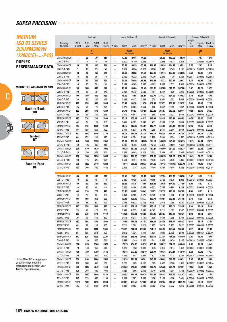
SUPER PRECISION
C
184 TIMKEN MACHINE TOOL CATALOG
MEDIUM ISO 03 SERIES 2(3)MM300WI (7300C(E)-...-P4S)DUPLEX PERFORMANCE DATA
(1) For DB or DF arrangements only. For other mounting arrangements, contact your Timken representative.
Preload Axial Stiffness(1) Radial Stiffness(1) Spacer Offsets(1)
Bearing Number
DUXX-light
DULLight
DUMMed.
DUHHeavy X-light Light Med. Heavy X-light Light Med. Heavy
X-light to
LightLight toMed.
Med. toHeavy
N lbs.
N/µm 106 lbs./in.
N/µm 106 lbs./in.
µm in.
2MM301WICR — 20 70 180 — 17.49 27.81 44.25 — 98.82 153.56 183.30 — 7.87 12.457301C-T-P4S — 5 15 40 — 0.100 0.159 0.253 — 0.565 0.878 1.048 — 0.00031 0.000492MM302WICR 20 40 110 220 — 27.46 40.93 57.19 109.97 143.24 164.93 205.51 3.70 7.87 9.147302C-T-P4S 5 10 25 50 — 0.157 0.234 0.327 0.628 0.819 0.943 1.175 0.00015 0.00031 0.000362MM303WICR 40 70 160 310 — 26.58 38.83 54.57 127.92 147.44 197.46 263.05 3.63 10.92 13.467303C-T-P4S 10 15 35 70 — 0.152 0.222 0.312 0.730 0.843 1.129 1.504 0.00014 0.00043 0.000532MM304WICR 40 90 220 400 — 33.06 49.85 66.46 140.53 181.72 232.97 289.81 6.14 12.95 12.927304C-T-P4S 10 20 50 90 — 0.189 0.285 0.380 0.803 1.039 1.332 1.657 0.00024 0.00051 0.000512MM305WICR 90 160 330 620 — 46.17 65.24 88.50 203.85 247.83 318.78 387.86 6.42 12.70 14.997305C-T-P4S 20 35 75 140 — 0.264 0.373 0.506 1.164 1.417 1.820 2.215 0.00025 0.00050 0.000592MM306WICR 90 180 440 780 — 49.50 74.68 98.47 223.77 271.27 394.56 470.83 7.73 17.27 15.497306C-T-P4S 20 40 100 175 — 0.283 0.427 0.563 1.278 1.551 2.253 2.689 0.00030 0.00068 0.000612MM307WICR 110 220 560 1000 — 55.97 85.18 114.38 251.87 323.91 438.09 526.52 9.05 18.80 17.787307C-T-P4S 25 50 125 225 — 0.320 0.487 0.654 1.438 1.852 2.502 3.007 0.00036 0.00074 0.000702MM308WICR 130 290 670 1220 — 64.71 94.62 127.85 290.33 364.67 512.52 620.41 10.56 19.05 20.077308C-T-P4S 30 65 150 275 — 0.370 0.541 0.731 1.658 2.085 2.927 3.543 0.00042 0.00075 0.000792MM309WICR 180 330 780 1560 — 70.13 103.02 145.17 313.69 393.18 520.48 646.82 10.00 20.57 25.157309C-T-P4S 40 75 175 350 — 0.401 0.589 0.830 1.791 2.248 2.972 3.694 0.00039 0.00081 0.000992MM310WICR 220 440 1000 1780 — 81.15 117.36 156.01 347.72 445.06 580.34 694.99 12.52 22.35 22.867310C-T-P4S 50 100 225 400 — 0.464 0.671 0.892 1.986 2.541 3.314 3.969 0.00049 0.00088 0.000902MM311WICR 270 560 1110 2110 — 88.15 121.38 167.20 383.15 496.30 622.37 761.00 15.05 21.34 27.697311C-T-P4S 60 125 250 475 — 0.504 0.694 0.956 2.188 2.834 3.554 4.346 0.00059 0.00084 0.001092MM312WICR 270 560 1330 2450 — 89.72 133.80 180.85 387.61 506.89 675.70 816.95 14.75 27.94 28.197312C-T-P4S 60 125 300 550 — 0.513 0.765 1.034 2.213 2.895 3.859 4.665 0.00058 0.00110 0.001112MM313WICR 330 670 1670 3000 — 104.24 157.93 211.28 453.84 585.60 791.90 952.23 14.55 30.48 28.967313C-T-P4S 75 150 375 675 — 0.596 0.903 1.208 2.592 3.344 4.522 5.438 0.00057 0.00120 0.001142MM314WICR 400 780 1890 3450 — 110.89 166.33 224.22 498.33 633.95 848.58 1024.31 15.49 32.26 32.007314C-T-P4S 90 175 425 775 — 0.634 0.951 1.282 2.846 3.620 4.846 5.849 0.00061 0.00127 0.001262MM319WICR 670 1330 3110 6230 — 140.44 206.03 290.33 611.00 787.43 1041.02 1293.71 21.67 41.05 50.247319C-T-P4S 150 300 700 1400 — 0.803 1.178 1.660 3.489 4.497 5.945 7.388 0.00085 0.00162 0.00198
3MM301WICR 40 90 180 310 — 58.59 76.61 96.37 96.32 122.54 153.78 183.56 3.42 5.33 6.107301E-T-P4S 10 20 40 70 — 0.335 0.438 0.551 0.550 0.700 0.878 1.048 0.00013 0.00021 0.000243MM302WICR 40 90 180 360 — 66.46 86.75 115.08 108.95 139.15 174.90 217.90 2.99 4.57 7.117302E-T-P4S 10 20 40 80 — 0.380 0.496 0.658 0.622 0.795 0.999 1.244 0.00012 0.00018 0.000283MM303WICR 40 110 270 440 — 63.66 89.02 109.49 93.69 132.92 176.19 207.22 4.85 8.13 7.117303E-T-P4S 10 25 60 100 — 0.364 0.509 0.626 0.535 0.760 1.006 1.183 0.00019 0.00032 0.000283MM304WICR 90 160 360 620 — 79.23 108.96 136.77 136.71 159.51 220.02 261.18 3.70 8.38 8.647304E-T-P4S 20 35 80 140 — 0.453 0.623 0.782 0.781 0.912 1.258 1.491 0.00015 0.00033 0.000343MM305WICR 110 220 530 890 — 101.62 142.19 174.90 165.18 212.03 283.21 333.10 4.90 10.16 8.897305E-T-P4S 25 50 120 200 — 0.581 0.813 1.000 0.943 1.211 1.617 1.902 0.00019 0.00040 0.000353MM306WICR 135 270 670 1110 — 112.29 159.33 196.06 193.95 252.07 342.44 403.21 4.99 11.68 9.917306E-T-P4S 30 60 150 250 — 0.642 0.911 1.121 1.108 1.439 1.955 2.303 0.00020 0.00046 0.000393MM307WICR 180 360 850 1560 — 134.85 187.84 241.01 221.46 284.26 378.37 459.17 5.93 12.19 13.217307E-T-P4S 40 80 190 350 — 0.771 1.074 1.378 1.265 1.623 2.161 2.622 0.00023 0.00048 0.000523MM308WICR 220 440 1110 1780 — 150.41 214.08 259.20 261.11 336.84 456.64 530.40 6.22 14.48 11.187308E-T-P4S 50 100 250 400 — 0.860 1.224 1.482 1.491 1.923 2.608 3.029 0.00025 0.00057 0.000443MM309WICR 270 530 1330 2220 — 165.98 235.94 290.51 269.80 332.14 468.66 551.00 7.20 15.75 13.467309E-T-P4S 60 120 300 500 — 0.949 1.349 1.661 1.541 1.899 2.676 3.146 0.00028 0.00062 0.000533MM310WICR 310 620 1560 2670 — 178.75 254.13 316.57 293.47 360.12 510.36 605.40 7.83 17.27 15.497310E-T-P4S 70 140 350 600 — 1.022 1.453 1.810 1.676 2.059 2.914 3.457 0.00031 0.00068 0.000613MM311WICR 400 780 1780 3110 — 198.16 272.32 342.10 328.74 407.34 547.14 653.40 8.51 17.02 17.277311E-T-P4S 90 175 400 700 — 1.133 1.557 1.956 1.877 2.329 3.124 3.731 0.00034 0.00067 0.000683MM312WICR 450 890 2000 3560 — 213.38 291.21 367.81 347.62 450.02 582.53 699.31 9.35 17.53 18.807312E-T-P4S 100 200 450 800 — 1.220 1.665 2.103 1.985 2.573 3.326 3.993 0.00037 0.00069 0.000743MM313WICR 560 1110 2670 4450 — 249.23 348.93 429.55 409.70 525.26 701.21 824.51 10.03 20.83 18.297313E-T-P4S 125 250 600 1000 — 1.425 1.995 2.456 2.340 2.999 4.004 4.708 0.00039 0.00082 0.000723MM314WICR 620 1220 2890 5120 — 262.52 365.02 460.34 433.61 552.97 735.10 881.07 10.22 21.08 21.597314E-T-P4S 140 275 650 1150 — 1.501 2.087 2.632 2.476 3.158 4.198 5.031 0.00040 0.00083 0.000853MM319WICR 1070 2110 4890 8900 — 328.81 453.52 578.22 541.62 692.64 914.62 1105.79 14.24 28.19 30.997319E-T-P4S 240 475 1100 2000 — 1.880 2.593 3.306 3.093 3.955 5.223 6.315 0.00056 0.00111 0.00122
MOUNTING ARRANGEMENTS
Back-to-BackDB
TandemDT
Face-to-FaceDF
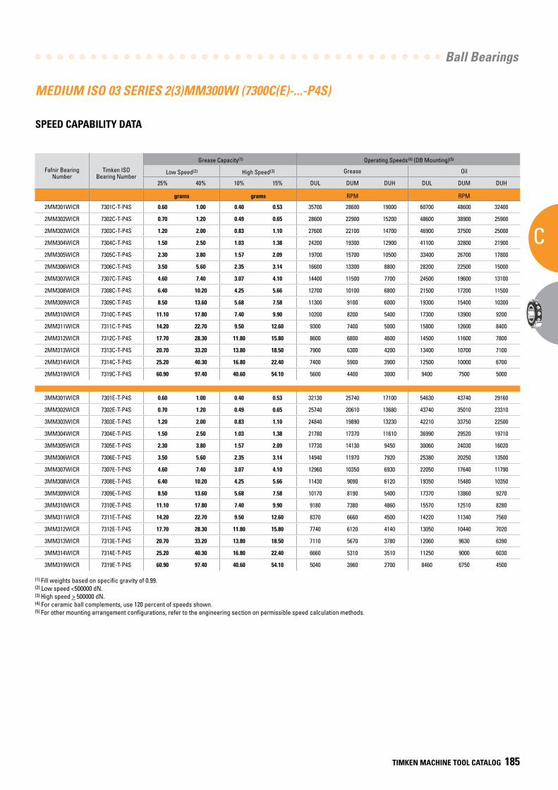
Ball Bearings
C
TIMKEN MACHINE TOOL CATALOG 185
MEDIUM ISO 03 SERIES 2(3)MM300WI (7300C(E)-...-P4S)
SPEED CAPABILITY DATA
Fafnir Bearing Number
Timken ISO Bearing Number
Grease Capacity(1) Operating Speeds(4) (DB Mounting)(5)
Low Speed(2) High Speed(3) Grease Oil
25% 40% 10% 15% DUL DUM DUH DUL DUM DUH
grams grams RPM RPM
2MM301WICR 7301C-T-P4S 0.60 1.00 0.40 0.53 35700 28600 19000 60700 48600 32400
2MM302WICR 7302C-T-P4S 0.70 1.20 0.49 0.65 28600 22900 15200 48600 38900 25900
2MM303WICR 7303C-T-P4S 1.20 2.00 0.83 1.10 27600 22100 14700 46900 37500 25000
2MM304WICR 7304C-T-P4S 1.50 2.50 1.03 1.38 24200 19300 12900 41100 32800 21900
2MM305WICR 7305C-T-P4S 2.30 3.80 1.57 2.09 19700 15700 10500 33400 26700 17800
2MM306WICR 7306C-T-P4S 3.50 5.60 2.35 3.14 16600 13300 8800 28200 22500 15000
2MM307WICR 7307C-T-P4S 4.60 7.40 3.07 4.10 14400 11500 7700 24500 19600 13100
2MM308WICR 7308C-T-P4S 6.40 10.20 4.25 5.66 12700 10100 6800 21500 17200 11500
2MM309WICR 7309C-T-P4S 8.50 13.60 5.68 7.58 11300 9100 6000 19300 15400 10300
2MM310WICR 7310C-T-P4S 11.10 17.80 7.40 9.90 10200 8200 5400 17300 13900 9200
2MM311WICR 7311C-T-P4S 14.20 22.70 9.50 12.60 9300 7400 5000 15800 12600 8400
2MM312WICR 7312C-T-P4S 17.70 28.30 11.80 15.80 8600 6800 4600 14500 11600 7800
2MM313WICR 7313C-T-P4S 20.70 33.20 13.80 18.50 7900 6300 4200 13400 10700 7100
2MM314WICR 7314C-T-P4S 25.20 40.30 16.80 22.40 7400 5900 3900 12500 10000 6700
2MM319WICR 7319C-T-P4S 60.90 97.40 40.60 54.10 5600 4400 3000 9400 7500 5000
3MM301WICR 7301E-T-P4S 0.60 1.00 0.40 0.53 32130 25740 17100 54630 43740 29160
3MM302WICR 7302E-T-P4S 0.70 1.20 0.49 0.65 25740 20610 13680 43740 35010 23310
3MM303WICR 7303E-T-P4S 1.20 2.00 0.83 1.10 24840 19890 13230 42210 33750 22500
3MM304WICR 7304E-T-P4S 1.50 2.50 1.03 1.38 21780 17370 11610 36990 29520 19710
3MM305WICR 7305E-T-P4S 2.30 3.80 1.57 2.09 17730 14130 9450 30060 24030 16020
3MM306WICR 7306E-T-P4S 3.50 5.60 2.35 3.14 14940 11970 7920 25380 20250 13500
3MM307WICR 7307E-T-P4S 4.60 7.40 3.07 4.10 12960 10350 6930 22050 17640 11790
3MM308WICR 7308E-T-P4S 6.40 10.20 4.25 5.66 11430 9090 6120 19350 15480 10350
3MM309WICR 7309E-T-P4S 8.50 13.60 5.68 7.58 10170 8190 5400 17370 13860 9270
3MM310WICR 7310E-T-P4S 11.10 17.80 7.40 9.90 9180 7380 4860 15570 12510 8280
3MM311WICR 7311E-T-P4S 14.20 22.70 9.50 12.60 8370 6660 4500 14220 11340 7560
3MM312WICR 7312E-T-P4S 17.70 28.30 11.80 15.80 7740 6120 4140 13050 10440 7020
3MM313WICR 7313E-T-P4S 20.70 33.20 13.80 18.50 7110 5670 3780 12060 9630 6390
3MM314WICR 7314E-T-P4S 25.20 40.30 16.80 22.40 6660 5310 3510 11250 9000 6030
3MM319WICR 7319E-T-P4S 60.90 97.40 40.60 54.10 5040 3960 2700 8460 6750 4500
(1) Fill weights based on specific gravity of 0.99.(2) Low speed <500000 dN.(3) High speed > 500000 dN.(4) For ceramic ball complements, use 120 percent of speeds shown.(5) For other mounting arrangement configurations, refer to the engineering section on permissible speed calculation methods.
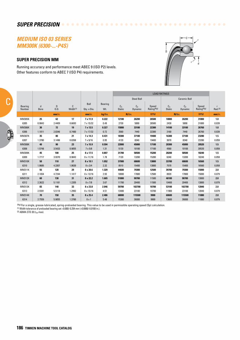
SUPER PRECISION
C
186 TIMKEN MACHINE TOOL CATALOG
C
D
r
dr
(Ng) For a single, grease-lubricated, spring-preloaded bearing. This value to be used in permissible operating speed (Sp) calculation.(1) Width tolerance of preloaded bearing set +0.000/-0.254 mm (+0.0000/-0.0100 in.).(2) ABMA STD 20 (ras max).
MEDIUM ISO 03 SERIES MM300K (6300-...-P4S)
SUPER PRECISION MM
Running accuracy and performance meet ABEC 9 (ISO P2) levels. Other features conform to ABEC 7 (ISO P4) requirements.
BearingNumber
dBore
DO.D.
CWidth(1)
Ball Bearing
LOAD RATINGS
rRad.(2)
Suggested Shoulder Diameters Shaft Diameter Mounting Fits
FIXED FLOATING
Steel Ball Ceramic Ball Housing Bore (Stationary) Mounting Fits Housing Bore
(Stationary) Mounting Fits
CoStatic
CeDynamic
SpeedRating(Ng)
CoStatic
CeDynamic
SpeedRating(Ng)
Shaft Housing
Qty. x Dia. Wt. Max. Min. Max. Min. Max. Min. Loose Tight Max. Min. Tight Loose Max. Min. Loose Loose
mm/in. mm/in. kg/lbs. N/lbs. RPM N/lbs. RPM mm/in. mm/in. mm/in. mm/in. mm/in. mm/in. mm/in. mm/in. mm/in.
MM305K 25 62 17 7 x 11.9 0.222 12100 26200 26500 10800 26200 31800 1.0 32.1 31.9 55.8 55.5 25.000 24.995 0.005 0.005 62.008 62.000 0.000 0.015 62.012 62.007 0.019 0.007
6305 0.9843 2.4409 0.6693 7 x 15/32 0.49 2730 5890 26500 2430 5890 31800 0.039 1.27 1.26 2.20 2.19 0.98430 0.98410 0.00020 0.00020 2.44120 2.44090 0.00000 0.00060 2.44140 2.44120 0.00080 0.00030
MM306K 30 72 19 7 x 13.5 0.327 15800 33100 22300 14100 33100 26760 1.0 37.7 37.5 65.2 64.9 30.000 29.995 0.005 0.005 72.008 72.000 0.000 0.015 72.011 72.007 0.019 0.007
6306 1.1811 2.8346 0.7480 7 x 17/32 0.72 3560 7440 22300 3160 7440 26760 0.039 1.49 1.48 2.57 2.56 1.18110 1.18090 0.00020 0.00020 2.83490 2.83460 0.00000 0.00060 2.83510 2.83490 0.00080 0.00030
MM307K 35 80 21 7 x 14.3 0.431 18300 37100 19400 16300 37100 23280 1.5 43.7 43.2 72.1 71.6 35.000 34.995 0.005 0.006 80.008 80.000 0.000 0.015 80.012 80.008 0.020 0.008
6307 1.3780 3.1496 0.8268 7 x 9/16 0.95 4120 8340 19400 3670 8340 23280 0.059 1.72 1.70 2.84 2.82 1.37800 1.37780 0.00020 0.00025 3.14990 3.14960 0.00000 0.00060 3.15010 3.14990 0.00080 0.00030
MM308K 40 90 23 7 x 15.9 0.594 22800 45000 17100 20300 45000 20520 1.5 49.8 49.3 81.3 80.8 40.000 39.995 0.005 0.006 90.008 90.000 0.000 0.016 90.015 90.007 0.023 0.007
6308 1.5748 3.5433 0.9055 7 x 5/8 1.31 5120 10100 17100 4560 10100 20520 0.059 1.96 1.94 3.20 3.18 1.57480 1.57460 0.00020 0.00025 3.54360 3.54330 0.00000 0.00060 3.54390 3.54360 0.00090 0.00030
MM309K 45 100 25 8 x 17.5 0.807 31700 58500 15200 28200 58500 18240 1.5 55.9 55.4 90.2 89.7 45.000 44.995 0.005 0.006 100.008 100.000 0.000 0.016 100.018 100.010 0.025 0.010
6309 1.7717 3.9370 0.9843 8 x 11/16 1.78 7120 13200 15200 6340 13200 18240 0.059 2.20 2.18 3.55 3.53 1.77170 1.77150 0.00020 0.00025 3.93730 3.93700 0.00000 0.00060 3.93770 3.93740 0.00100 0.00040
MM310K 50 110 27 8 x 19.1 1.052 37900 68600 13800 33700 68600 16560 1.5 61.2 60.7 99.8 99.3 50.000 49.995 0.005 0.006 110.008 110.000 0.000 0.016 110.018 110.010 0.025 0.010
6310 1.9685 4.3307 1.0630 8 x 3/4 2.32 8510 15400 13800 7570 15400 16560 0.059 2.41 2.39 3.93 3.91 1.96850 1.96830 0.00020 0.00025 4.33100 4.33070 0.00000 0.00060 4.33140 4.33110 0.00100 0.00040
MM311K 55 120 29 8 x 20.6 1.329 44600 79300 12500 39700 79300 15000 2.0 67.3 66.8 108.7 108.2 55.000 54.995 0.005 0.007 120.008 120.000 0.000 0.016 120.018 120.010 0.025 0.010
6311 2.1654 4.7244 1.1417 8 x 13/16 2.93 10000 17800 12500 8920 17800 15000 0.079 2.65 2.63 4.28 4.26 2.16540 2.16520 0.00020 0.00030 4.72470 4.72440 0.00000 0.00060 4.72510 4.72480 0.00100 0.00040
MM312K 60 130 31 8 x 22.2 1.665 51800 90700 11500 46100 90700 13800 2.0 43.2 72.6 117.9 117.3 60.000 59.995 0.005 0.007 130.009 130.000 0.000 0.018 130.020 130.010 0.029 0.010
6312 2.3622 5.1181 1.2205 8 x 7/8 3.67 11700 20400 11500 10400 20400 13800 0.079 2.88 2.86 4.64 4.62 2.36220 2.36200 0.00020 0.00030 5.11850 5.11810 0.00000 0.00070 5.11890 5.11850 0.00110 0.00040
MM313K 65 140 33 8 x 23.8 2.046 59700 102700 10700 53100 102700 12840 2.0 80.3 79.8 126.8 126.2 65.000 64.995 0.005 0.007 140.009 140.000 0.000 0.018 140.020 140.010 0.029 0.010
6313 2.5591 5.5118 1.2992 8 x 15/16 4.51 13400 23100 10700 11900 23100 12840 0.079 3.16 3.14 4.99 4.97 2.55910 2.55890 0.00020 0.00030 5.51220 5.51180 0.00000 0.00070 5.51260 5.51220 0.00110 0.00040
MM314K 70 150 35 8 x 25.4 2.486 68000 115500 9900 60600 115500 11880 2.0 85.3 84.8 135.6 135.1 70.000 69.995 0.005 0.007 150.009 150.000 0.000 0.018 150.023 150.012 0.032 0.012
6314 2.7559 5.9055 1.3780 8 x 1 5.48 15300 26000 9900 13600 26000 11880 0.079 3.36 3.34 5.34 5.32 2.75590 2.75570 0.00020 0.00030 5.90590 5.90550 0.00000 0.00070 5.90640 5.90600 0.00120 0.00050
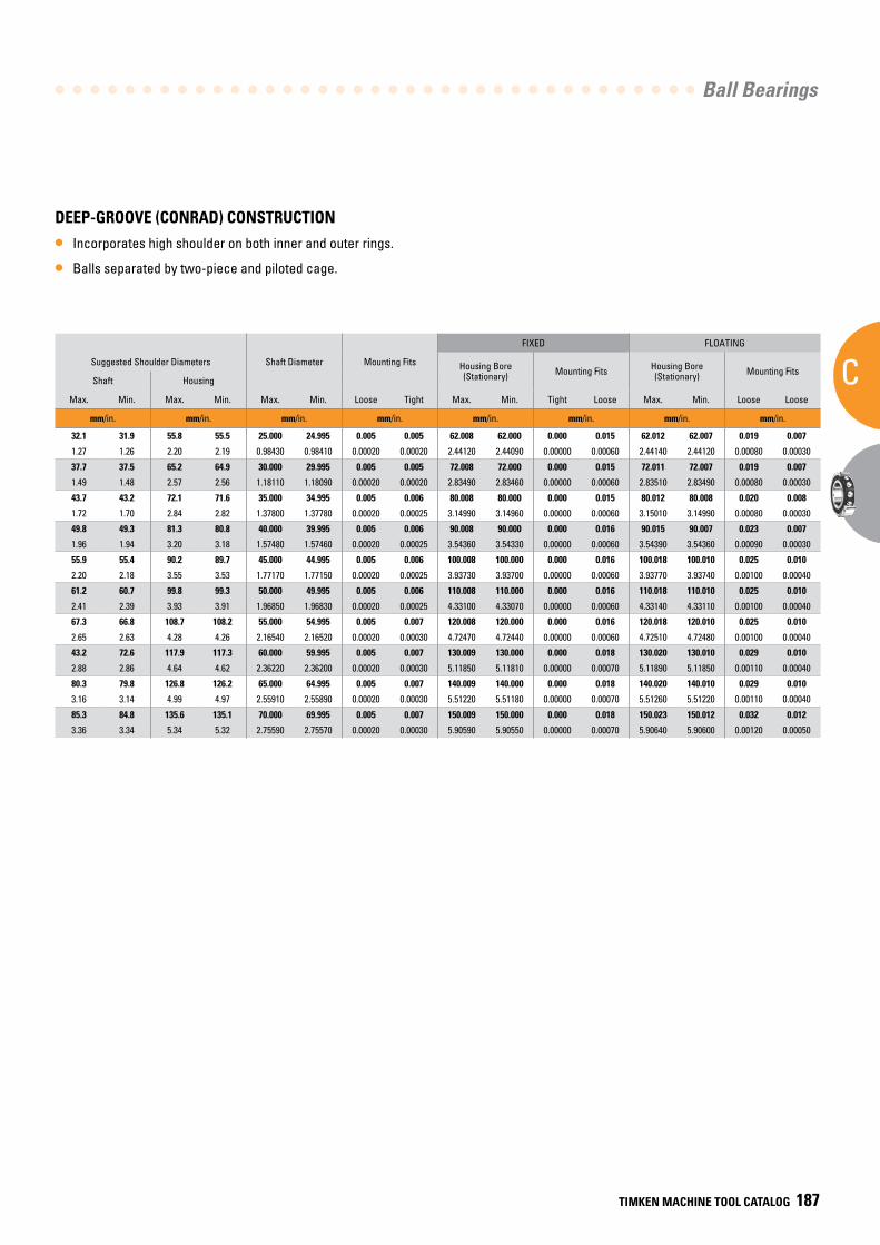
Ball Bearings
C
TIMKEN MACHINE TOOL CATALOG 187
DEEP-GROOVE (CONRAD) CONSTRUCTION
• Incorporates high shoulder on both inner and outer rings.
• Balls separated by two-piece and piloted cage.
BearingNumber
dBore
DO.D.
CWidth(1)
Ball Bearing
LOAD RATINGS
rRad.(2)
Suggested Shoulder Diameters Shaft Diameter Mounting Fits
FIXED FLOATING
Steel Ball Ceramic Ball Housing Bore (Stationary) Mounting Fits Housing Bore
(Stationary) Mounting Fits
CoStatic
CeDynamic
SpeedRating(Ng)
CoStatic
CeDynamic
SpeedRating(Ng)
Shaft Housing
Qty. x Dia. Wt. Max. Min. Max. Min. Max. Min. Loose Tight Max. Min. Tight Loose Max. Min. Loose Loose
mm/in. mm/in. kg/lbs. N/lbs. RPM N/lbs. RPM mm/in. mm/in. mm/in. mm/in. mm/in. mm/in. mm/in. mm/in. mm/in.
MM305K 25 62 17 7 x 11.9 0.222 12100 26200 26500 10800 26200 31800 1.0 32.1 31.9 55.8 55.5 25.000 24.995 0.005 0.005 62.008 62.000 0.000 0.015 62.012 62.007 0.019 0.007
6305 0.9843 2.4409 0.6693 7 x 15/32 0.49 2730 5890 26500 2430 5890 31800 0.039 1.27 1.26 2.20 2.19 0.98430 0.98410 0.00020 0.00020 2.44120 2.44090 0.00000 0.00060 2.44140 2.44120 0.00080 0.00030
MM306K 30 72 19 7 x 13.5 0.327 15800 33100 22300 14100 33100 26760 1.0 37.7 37.5 65.2 64.9 30.000 29.995 0.005 0.005 72.008 72.000 0.000 0.015 72.011 72.007 0.019 0.007
6306 1.1811 2.8346 0.7480 7 x 17/32 0.72 3560 7440 22300 3160 7440 26760 0.039 1.49 1.48 2.57 2.56 1.18110 1.18090 0.00020 0.00020 2.83490 2.83460 0.00000 0.00060 2.83510 2.83490 0.00080 0.00030
MM307K 35 80 21 7 x 14.3 0.431 18300 37100 19400 16300 37100 23280 1.5 43.7 43.2 72.1 71.6 35.000 34.995 0.005 0.006 80.008 80.000 0.000 0.015 80.012 80.008 0.020 0.008
6307 1.3780 3.1496 0.8268 7 x 9/16 0.95 4120 8340 19400 3670 8340 23280 0.059 1.72 1.70 2.84 2.82 1.37800 1.37780 0.00020 0.00025 3.14990 3.14960 0.00000 0.00060 3.15010 3.14990 0.00080 0.00030
MM308K 40 90 23 7 x 15.9 0.594 22800 45000 17100 20300 45000 20520 1.5 49.8 49.3 81.3 80.8 40.000 39.995 0.005 0.006 90.008 90.000 0.000 0.016 90.015 90.007 0.023 0.007
6308 1.5748 3.5433 0.9055 7 x 5/8 1.31 5120 10100 17100 4560 10100 20520 0.059 1.96 1.94 3.20 3.18 1.57480 1.57460 0.00020 0.00025 3.54360 3.54330 0.00000 0.00060 3.54390 3.54360 0.00090 0.00030
MM309K 45 100 25 8 x 17.5 0.807 31700 58500 15200 28200 58500 18240 1.5 55.9 55.4 90.2 89.7 45.000 44.995 0.005 0.006 100.008 100.000 0.000 0.016 100.018 100.010 0.025 0.010
6309 1.7717 3.9370 0.9843 8 x 11/16 1.78 7120 13200 15200 6340 13200 18240 0.059 2.20 2.18 3.55 3.53 1.77170 1.77150 0.00020 0.00025 3.93730 3.93700 0.00000 0.00060 3.93770 3.93740 0.00100 0.00040
MM310K 50 110 27 8 x 19.1 1.052 37900 68600 13800 33700 68600 16560 1.5 61.2 60.7 99.8 99.3 50.000 49.995 0.005 0.006 110.008 110.000 0.000 0.016 110.018 110.010 0.025 0.010
6310 1.9685 4.3307 1.0630 8 x 3/4 2.32 8510 15400 13800 7570 15400 16560 0.059 2.41 2.39 3.93 3.91 1.96850 1.96830 0.00020 0.00025 4.33100 4.33070 0.00000 0.00060 4.33140 4.33110 0.00100 0.00040
MM311K 55 120 29 8 x 20.6 1.329 44600 79300 12500 39700 79300 15000 2.0 67.3 66.8 108.7 108.2 55.000 54.995 0.005 0.007 120.008 120.000 0.000 0.016 120.018 120.010 0.025 0.010
6311 2.1654 4.7244 1.1417 8 x 13/16 2.93 10000 17800 12500 8920 17800 15000 0.079 2.65 2.63 4.28 4.26 2.16540 2.16520 0.00020 0.00030 4.72470 4.72440 0.00000 0.00060 4.72510 4.72480 0.00100 0.00040
MM312K 60 130 31 8 x 22.2 1.665 51800 90700 11500 46100 90700 13800 2.0 43.2 72.6 117.9 117.3 60.000 59.995 0.005 0.007 130.009 130.000 0.000 0.018 130.020 130.010 0.029 0.010
6312 2.3622 5.1181 1.2205 8 x 7/8 3.67 11700 20400 11500 10400 20400 13800 0.079 2.88 2.86 4.64 4.62 2.36220 2.36200 0.00020 0.00030 5.11850 5.11810 0.00000 0.00070 5.11890 5.11850 0.00110 0.00040
MM313K 65 140 33 8 x 23.8 2.046 59700 102700 10700 53100 102700 12840 2.0 80.3 79.8 126.8 126.2 65.000 64.995 0.005 0.007 140.009 140.000 0.000 0.018 140.020 140.010 0.029 0.010
6313 2.5591 5.5118 1.2992 8 x 15/16 4.51 13400 23100 10700 11900 23100 12840 0.079 3.16 3.14 4.99 4.97 2.55910 2.55890 0.00020 0.00030 5.51220 5.51180 0.00000 0.00070 5.51260 5.51220 0.00110 0.00040
MM314K 70 150 35 8 x 25.4 2.486 68000 115500 9900 60600 115500 11880 2.0 85.3 84.8 135.6 135.1 70.000 69.995 0.005 0.007 150.009 150.000 0.000 0.018 150.023 150.012 0.032 0.012
6314 2.7559 5.9055 1.3780 8 x 1 5.48 15300 26000 9900 13600 26000 11880 0.079 3.36 3.34 5.34 5.32 2.75590 2.75570 0.00020 0.00030 5.90590 5.90550 0.00000 0.00070 5.90640 5.90600 0.00120 0.00050
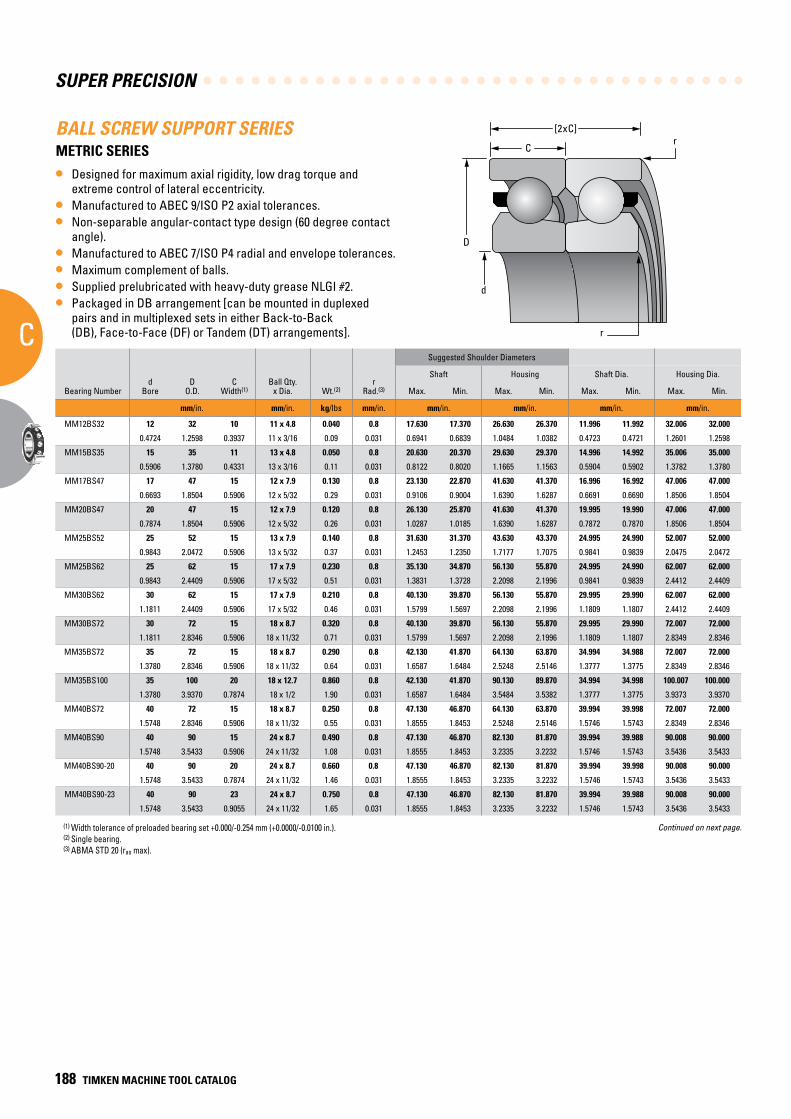
SUPER PRECISION
C
188 TIMKEN MACHINE TOOL CATALOG
d
r
C
D
r[2xC]BALL SCREW SUPPORT SERIES
METRIC SERIES
• Designed for maximum axial rigidity, low drag torque and extreme control of lateral eccentricity.
• Manufactured to ABEC 9/ISO P2 axial tolerances.• Non-separable angular-contact type design (60 degree contact
angle).• Manufactured to ABEC 7/ISO P4 radial and envelope tolerances.• Maximum complement of balls.• Supplied prelubricated with heavy-duty grease NLGI #2.• Packaged in DB arrangement [can be mounted in duplexed
pairs and in multiplexed sets in either Back-to-Back (DB), Face-to-Face (DF) or Tandem (DT) arrangements].
Suggested Shoulder Diameters
Bearing Numberd
BoreD
O.D.C
Width(1)Ball Qty.
x Dia. Wt.(2)r
Rad.(3)
Shaft Housing Shaft Dia. Housing Dia.
Max. Min. Max. Min. Max. Min. Max. Min.
mm/in. mm/in. kg/lbs mm/in. mm/in. mm/in. mm/in. mm/in.
MM12BS32 12 32 10 11 x 4.8 0.040 0.8 17.630 17.370 26.630 26.370 11.996 11.992 32.006 32.000
0.4724 1.2598 0.3937 11 x 3/16 0.09 0.031 0.6941 0.6839 1.0484 1.0382 0.4723 0.4721 1.2601 1.2598
MM15BS35 15 35 11 13 x 4.8 0.050 0.8 20.630 20.370 29.630 29.370 14.996 14.992 35.006 35.000
0.5906 1.3780 0.4331 13 x 3/16 0.11 0.031 0.8122 0.8020 1.1665 1.1563 0.5904 0.5902 1.3782 1.3780
MM17BS47 17 47 15 12 x 7.9 0.130 0.8 23.130 22.870 41.630 41.370 16.996 16.992 47.006 47.000
0.6693 1.8504 0.5906 12 x 5/32 0.29 0.031 0.9106 0.9004 1.6390 1.6287 0.6691 0.6690 1.8506 1.8504
MM20BS47 20 47 15 12 x 7.9 0.120 0.8 26.130 25.870 41.630 41.370 19.995 19.990 47.006 47.000
0.7874 1.8504 0.5906 12 x 5/32 0.26 0.031 1.0287 1.0185 1.6390 1.6287 0.7872 0.7870 1.8506 1.8504
MM25BS52 25 52 15 13 x 7.9 0.140 0.8 31.630 31.370 43.630 43.370 24.995 24.990 52.007 52.000
0.9843 2.0472 0.5906 13 x 5/32 0.37 0.031 1.2453 1.2350 1.7177 1.7075 0.9841 0.9839 2.0475 2.0472
MM25BS62 25 62 15 17 x 7.9 0.230 0.8 35.130 34.870 56.130 55.870 24.995 24.990 62.007 62.000
0.9843 2.4409 0.5906 17 x 5/32 0.51 0.031 1.3831 1.3728 2.2098 2.1996 0.9841 0.9839 2.4412 2.4409
MM30BS62 30 62 15 17 x 7.9 0.210 0.8 40.130 39.870 56.130 55.870 29.995 29.990 62.007 62.000
1.1811 2.4409 0.5906 17 x 5/32 0.46 0.031 1.5799 1.5697 2.2098 2.1996 1.1809 1.1807 2.4412 2.4409
MM30BS72 30 72 15 18 x 8.7 0.320 0.8 40.130 39.870 56.130 55.870 29.995 29.990 72.007 72.000
1.1811 2.8346 0.5906 18 x 11/32 0.71 0.031 1.5799 1.5697 2.2098 2.1996 1.1809 1.1807 2.8349 2.8346
MM35BS72 35 72 15 18 x 8.7 0.290 0.8 42.130 41.870 64.130 63.870 34.994 34.988 72.007 72.000
1.3780 2.8346 0.5906 18 x 11/32 0.64 0.031 1.6587 1.6484 2.5248 2.5146 1.3777 1.3775 2.8349 2.8346
MM35BS100 35 100 20 18 x 12.7 0.860 0.8 42.130 41.870 90.130 89.870 34.994 34.998 100.007 100.000
1.3780 3.9370 0.7874 18 x 1/2 1.90 0.031 1.6587 1.6484 3.5484 3.5382 1.3777 1.3775 3.9373 3.9370
MM40BS72 40 72 15 18 x 8.7 0.250 0.8 47.130 46.870 64.130 63.870 39.994 39.998 72.007 72.000
1.5748 2.8346 0.5906 18 x 11/32 0.55 0.031 1.8555 1.8453 2.5248 2.5146 1.5746 1.5743 2.8349 2.8346
MM40BS90 40 90 15 24 x 8.7 0.490 0.8 47.130 46.870 82.130 81.870 39.994 39.988 90.008 90.000
1.5748 3.5433 0.5906 24 x 11/32 1.08 0.031 1.8555 1.8453 3.2335 3.2232 1.5746 1.5743 3.5436 3.5433
MM40BS90-20 40 90 20 24 x 8.7 0.660 0.8 47.130 46.870 82.130 81.870 39.994 39.998 90.008 90.000
1.5748 3.5433 0.7874 24 x 11/32 1.46 0.031 1.8555 1.8453 3.2335 3.2232 1.5746 1.5743 3.5436 3.5433
MM40BS90-23 40 90 23 24 x 8.7 0.750 0.8 47.130 46.870 82.130 81.870 39.994 39.988 90.008 90.000
1.5748 3.5433 0.9055 24 x 11/32 1.65 0.031 1.8555 1.8453 3.2335 3.2232 1.5746 1.5743 3.5436 3.5433
Continued on next page.(1) Width tolerance of preloaded bearing set +0.000/-0.254 mm (+0.0000/-0.0100 in.). (2) Single bearing. (3) ABMA STD 20 (ras max).
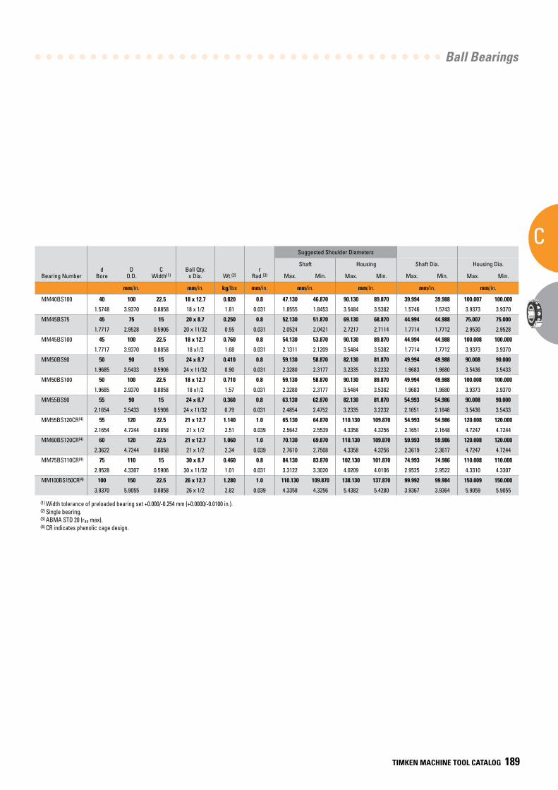
Ball Bearings
C
TIMKEN MACHINE TOOL CATALOG 189
Suggested Shoulder Diameters
Bearing Numberd
BoreD
O.D.C
Width(1)Ball Qty.
x Dia. Wt.(2)r
Rad.(3)
Shaft Housing Shaft Dia. Housing Dia.
Max. Min. Max. Min. Max. Min. Max. Min.
mm/in. mm/in. kg/lbs mm/in. mm/in. mm/in. mm/in. mm/in.
MM40BS100 40 100 22.5 18 x 12.7 0.820 0.8 47.130 46.870 90.130 89.870 39.994 39.988 100.007 100.000
1.5748 3.9370 0.8858 18 x 1/2 1.81 0.031 1.8555 1.8453 3.5484 3.5382 1.5746 1.5743 3.9373 3.9370
MM45BS75 45 75 15 20 x 8.7 0.250 0.8 52.130 51.870 69.130 68.870 44.994 44.988 75.007 75.000
1.7717 2.9528 0.5906 20 x 11/32 0.55 0.031 2.0524 2.0421 2.7217 2.7114 1.7714 1.7712 2.9530 2.9528
MM45BS100 45 100 22.5 18 x 12.7 0.760 0.8 54.130 53.870 90.130 89.870 44.994 44.988 100.008 100.000
1.7717 3.9370 0.8858 18 x1/2 1.68 0.031 2.1311 2.1209 3.5484 3.5382 1.7714 1.7712 3.9373 3.9370
MM50BS90 50 90 15 24 x 8.7 0.410 0.8 59.130 58.870 82.130 81.870 49.994 49.988 90.008 90.000
1.9685 3.5433 0.5906 24 x 11/32 0.90 0.031 2.3280 2.3177 3.2335 3.2232 1.9683 1.9680 3.5436 3.5433
MM50BS100 50 100 22.5 18 x 12.7 0.710 0.8 59.130 58.870 90.130 89.870 49.994 49.988 100.008 100.000
1.9685 3.9370 0.8858 18 x1/2 1.57 0.031 2.3280 2.3177 3.5484 3.5382 1.9683 1.9680 3.9373 3.9370
MM55BS90 55 90 15 24 x 8.7 0.360 0.8 63.130 62.870 82.130 81.870 54.993 54.986 90.008 90.000
2.1654 3.5433 0.5906 24 x 11/32 0.79 0.031 2.4854 2.4752 3.2335 3.2232 2.1651 2.1648 3.5436 3.5433
MM55BS120CR(4) 55 120 22.5 21 x 12.7 1.140 1.0 65.130 64.870 110.130 109.870 54.993 54.986 120.008 120.000
2.1654 4.7244 0.8858 21 x 1/2 2.51 0.039 2.5642 2.5539 4.3358 4.3256 2.1651 2.1648 4.7247 4.7244
MM60BS120CR(4) 60 120 22.5 21 x 12.7 1.060 1.0 70.130 69.870 110.130 109.870 59.993 59.986 120.008 120.000
2.3622 4.7244 0.8858 21 x 1/2 2.34 0.039 2.7610 2.7508 4.3358 4.3256 2.3619 2.3617 4.7247 4.7244
MM75BS110CR(4) 75 110 15 30 x 8.7 0.460 0.8 84.130 83.870 102.130 101.870 74.993 74.986 110.008 110.000
2.9528 4.3307 0.5906 30 x 11/32 1.01 0.031 3.3122 3.3020 4.0209 4.0106 2.9525 2.9522 4.3310 4.3307
MM100BS150CR(4) 100 150 22.5 26 x 12.7 1.280 1.0 110.130 109.870 138.130 137.870 99.992 99.984 150.009 150.000
3.9370 5.9055 0.8858 26 x 1/2 2.82 0.039 4.3358 4.3256 5.4382 5.4280 3.9367 3.9364 5.9059 5.9055
(1) Width tolerance of preloaded bearing set +0.000/-0.254 mm (+0.0000/-0.0100 in.). (2) Single bearing. (3) ABMA STD 20 (ras max).(4) CR indicates phenolic cage design.
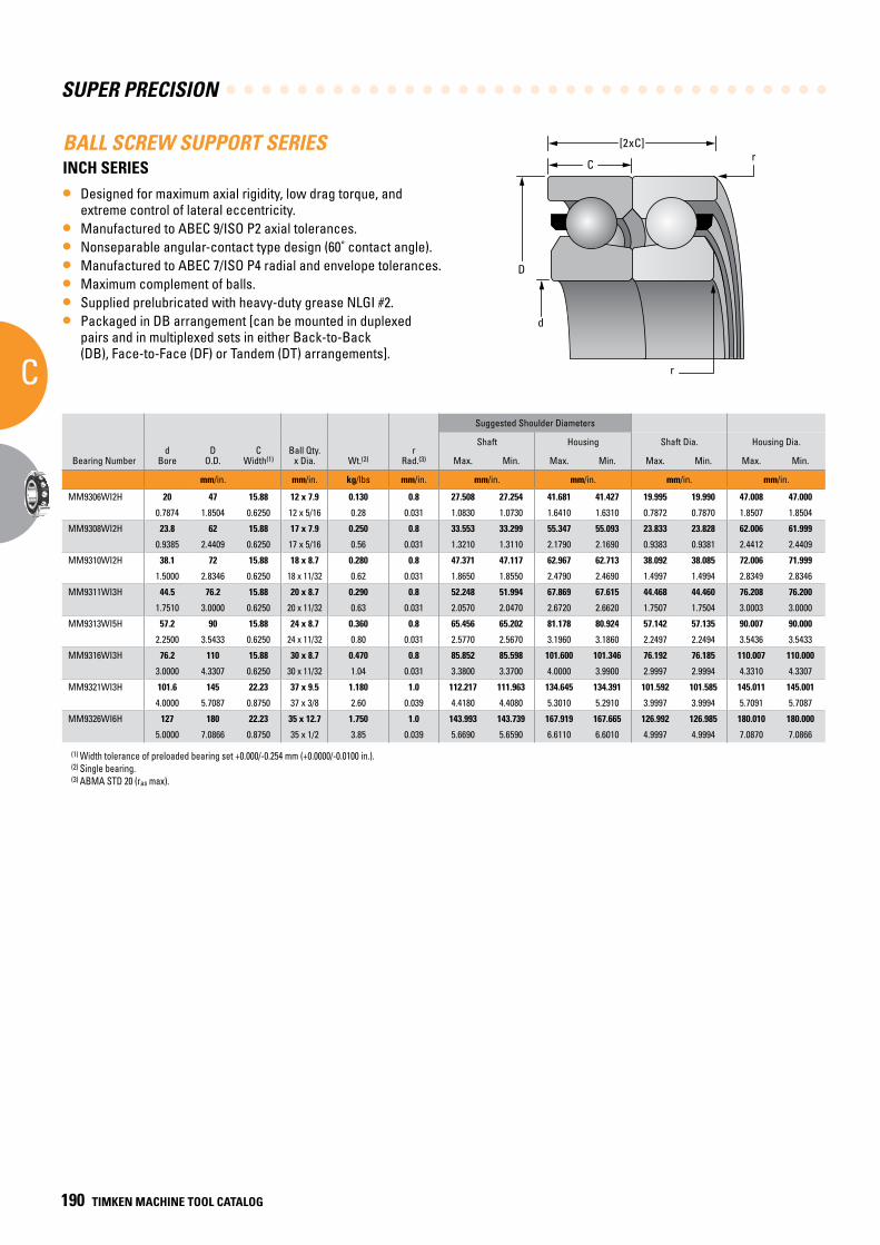
SUPER PRECISION
C
190 TIMKEN MACHINE TOOL CATALOG
BALL SCREW SUPPORT SERIESINCH SERIES
• Designed for maximum axial rigidity, low drag torque, and extreme control of lateral eccentricity.
• Manufactured to ABEC 9/ISO P2 axial tolerances.• Nonseparable angular-contact type design (60˚ contact angle).• Manufactured to ABEC 7/ISO P4 radial and envelope tolerances.• Maximum complement of balls.• Supplied prelubricated with heavy-duty grease NLGI #2.• Packaged in DB arrangement [can be mounted in duplexed
pairs and in multiplexed sets in either Back-to-Back (DB), Face-to-Face (DF) or Tandem (DT) arrangements].
Suggested Shoulder Diameters
Bearing Numberd
BoreD
O.D.C
Width(1)Ball Qty.
x Dia. Wt.(2)r
Rad.(3)
Shaft Housing Shaft Dia. Housing Dia.
Max. Min. Max. Min. Max. Min. Max. Min.
mm/in. mm/in. kg/lbs mm/in. mm/in. mm/in. mm/in. mm/in.
MM9306WI2H 20 47 15.88 12 x 7.9 0.130 0.8 27.508 27.254 41.681 41.427 19.995 19.990 47.008 47.000
0.7874 1.8504 0.6250 12 x 5/16 0.28 0.031 1.0830 1.0730 1.6410 1.6310 0.7872 0.7870 1.8507 1.8504
MM9308WI2H 23.8 62 15.88 17 x 7.9 0.250 0.8 33.553 33.299 55.347 55.093 23.833 23.828 62.006 61.999
0.9385 2.4409 0.6250 17 x 5/16 0.56 0.031 1.3210 1.3110 2.1790 2.1690 0.9383 0.9381 2.4412 2.4409
MM9310WI2H 38.1 72 15.88 18 x 8.7 0.280 0.8 47.371 47.117 62.967 62.713 38.092 38.085 72.006 71.999
1.5000 2.8346 0.6250 18 x 11/32 0.62 0.031 1.8650 1.8550 2.4790 2.4690 1.4997 1.4994 2.8349 2.8346
MM9311WI3H 44.5 76.2 15.88 20 x 8.7 0.290 0.8 52.248 51.994 67.869 67.615 44.468 44.460 76.208 76.200
1.7510 3.0000 0.6250 20 x 11/32 0.63 0.031 2.0570 2.0470 2.6720 2.6620 1.7507 1.7504 3.0003 3.0000
MM9313WI5H 57.2 90 15.88 24 x 8.7 0.360 0.8 65.456 65.202 81.178 80.924 57.142 57.135 90.007 90.000
2.2500 3.5433 0.6250 24 x 11/32 0.80 0.031 2.5770 2.5670 3.1960 3.1860 2.2497 2.2494 3.5436 3.5433
MM9316WI3H 76.2 110 15.88 30 x 8.7 0.470 0.8 85.852 85.598 101.600 101.346 76.192 76.185 110.007 110.000
3.0000 4.3307 0.6250 30 x 11/32 1.04 0.031 3.3800 3.3700 4.0000 3.9900 2.9997 2.9994 4.3310 4.3307
MM9321WI3H 101.6 145 22.23 37 x 9.5 1.180 1.0 112.217 111.963 134.645 134.391 101.592 101.585 145.011 145.001
4.0000 5.7087 0.8750 37 x 3/8 2.60 0.039 4.4180 4.4080 5.3010 5.2910 3.9997 3.9994 5.7091 5.7087
MM9326WI6H 127 180 22.23 35 x 12.7 1.750 1.0 143.993 143.739 167.919 167.665 126.992 126.985 180.010 180.000
5.0000 7.0866 0.8750 35 x 1/2 3.85 0.039 5.6690 5.6590 6.6110 6.6010 4.9997 4.9994 7.0870 7.0866
(1) Width tolerance of preloaded bearing set +0.000/-0.254 mm (+0.0000/-0.0100 in.). (2) Single bearing. (3) ABMA STD 20 (ras max).
d
r
C
D
r[2xC]
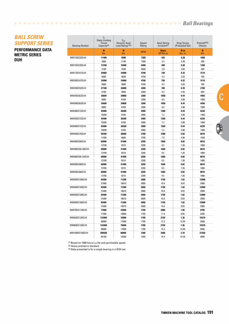
Ball Bearings
C
TIMKEN MACHINE TOOL CATALOG 191
BALL SCREW SUPPORT SERIESPERFORMANCE DATA METRIC SERIES DUH
(1) Based on 1500 hours L10 life and permissible speed.(2) Heavy preload is standard.(3) Data presented is for a single bearing in a DUH set.
Bearing Number
TL Static Limiting
Thrust Capacity(3)
CaeDynamic Axial
Load Rating(1)(3)SpeedRating
Axial SpringConstant(3)
Drag Torque(Preloaded Set)
Preload(2)(3)
(Heavy)
Nlbs.
Nlbs. RPM N/µm
106 lbs./inN-m
lbs.-in.N
lbs.
MM12BS32DUH 11400 9500 7300 425 0.28 10002600 2140 7300 2.4 2.48 200
MM15BS35DUH 13700 10400 6400 490 0.30 12003100 2340 6400 2.8 2.65 300
MM17BS47DUH 24900 24900 4700 750 0.32 31105600 5600 4700 4.3 2.83 700
MM20BS47DUH 24900 24900 4700 750 0.32 31105600 5600 4700 4.3 2.83 700
MM25BS52DUH 27100 26000 4300 780 0.39 27006100 5850 4300 4.5 3.45 600
MM25BS62DUH 35600 29800 3300 1050 0.44 44508000 6700 3300 6.0 3.88 1000
MM30BS62DUH 35600 29800 3300 1050 0.44 44508000 6700 3300 6.0 3.88 1000
MM30BS72DUH 45400 36300 2900 1260 0.44 623010200 8160 2900 7.2 3.88 1400
MM35BS72DUH 45400 36300 2900 1260 0.44 623010200 8160 2900 7.2 3.88 1400
MM40BS72DUH 45400 36300 2900 1260 0.44 623010200 8160 2900 7.2 3.88 1400
MM45BS75DUH 50700 38500 2700 1380 0.56 667011400 8660 2700 7.9 4.96 1500
MM40BS90DUH 60900 41400 2200 1660 0.82 801013700 9310 2200 9.5 7.26 1800
MM40BS90-20DUH 60900 41400 2200 1660 0.82 801013700 9310 2200 9.5 7.26 1800
MM40BS90-23DUH 60900 41400 2200 1660 0.82 801013700 9310 2200 9.5 7.26 1800
MM50BS90DUH 60900 41400 2200 1660 0.82 801013700 9310 2200 9.5 7.26 1800
MM55BS90DUH 60900 41400 2200 1660 0.82 801013700 9310 2200 9.5 7.26 1800
MM35BS100DUH 93400 71200 2000 1750 1.02 1290021000 16010 2000 10.0 9.03 2900
MM40BS100DUH 93400 71200 2000 1750 1.02 1290021000 16010 2000 10.0 9.03 2900
MM45BS100DUH 93400 71200 2000 1750 1.02 1290021000 16010 2000 10.0 9.03 2900
MM50BS100DUH 93400 71200 2000 1750 1.02 1290021000 16010 2000 10.0 9.03 2900
MM75BS110DUH 77000 44500 1700 2080 1.00 979017300 10000 1700 11.9 8.85 2200
MM55BS120DUH 133400 75600 1700 2150 1.36 1557030000 17000 1700 12.3 12.04 3500
MM60BS120DUH 133400 75600 1700 2150 1.36 1557030000 17000 1700 12.3 12.04 3500
MM100BS150DUH 200500 80900 1300 3400 2.18 2135045100 18200 1300 19.4 19.29 4800
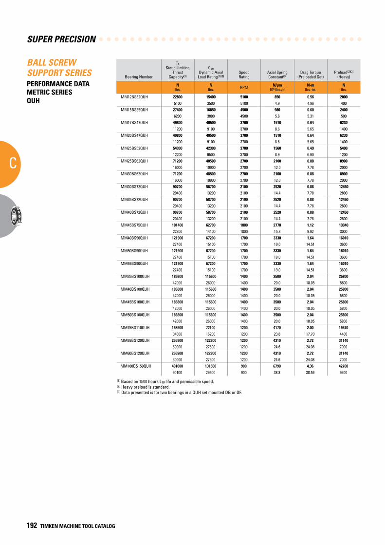
SUPER PRECISION
C
192 TIMKEN MACHINE TOOL CATALOG
BALL SCREW SUPPORT SERIESPERFORMANCE DATA METRIC SERIES QUH
Bearing Number
TL Static Limiting
Thrust Capacity(3)
CaeDynamic Axial
Load Rating(1)(3)SpeedRating
Axial SpringConstant(3)
Drag Torque(Preloaded Set)
Preload(2)(3)
(Heavy)
Nlbs.
Nlbs. RPM N/µm
106 lbs./inN-m
lbs.-in.N
lbs.
MM12BS32QUH 22800 15400 5100 850 0.56 20005100 3500 5100 4.9 4.96 400
MM15BS35QUH 27400 16850 4500 980 0.60 24006200 3800 4500 5.6 5.31 500
MM17BS47QUH 49800 40500 3700 1510 0.64 623011200 9100 3700 8.6 5.65 1400
MM20BS47QUH 49800 40500 3700 1510 0.64 623011200 9100 3700 8.6 5.65 1400
MM25BS52QUH 54300 42300 3700 1560 0.49 540012200 9500 3700 8.9 6.90 1200
MM25BS62QUH 71200 48500 2700 2100 0.88 890016000 10900 2700 12.0 7.78 2000
MM30BS62QUH 71200 48500 2700 2100 0.88 890016000 10900 2700 12.0 7.78 2000
MM30BS72QUH 90700 58700 2100 2520 0.88 1245020400 13200 2100 14.4 7.78 2800
MM35BS72QUH 90700 58700 2100 2520 0.88 1245020400 13200 2100 14.4 7.78 2800
MM40BS72QUH 90700 58700 2100 2520 0.88 1245020400 13200 2100 14.4 7.78 2800
MM45BS75QUH 101400 62700 1800 2770 1.12 1334022800 14100 1800 15.8 9.92 3000
MM40BS90QUH 121900 67200 1700 3330 1.64 1601027400 15100 1700 19.0 14.51 3600
MM50BS90QUH 121900 67200 1700 3330 1.64 1601027400 15100 1700 19.0 14.51 3600
MM55BS90QUH 121900 67200 1700 3330 1.64 1601027400 15100 1700 19.0 14.51 3600
MM35BS100QUH 186800 115600 1400 3500 2.04 2580042000 26000 1400 20.0 18.05 5800
MM40BS100QUH 186800 115600 1400 3500 2.04 2580042000 26000 1400 20.0 18.05 5800
MM45BS100QUH 186800 115600 1400 3500 2.04 2580042000 26000 1400 20.0 18.05 5800
MM50BS100QUH 186800 115600 1400 3500 2.04 2580042000 26000 1400 20.0 18.05 5800
MM75BS110QUH 153900 72100 1200 4170 2.00 1957034600 16200 1200 23.8 17.70 4400
MM55BS120QUH 266900 122800 1200 4310 2.72 3114060000 27600 1200 24.6 24.08 7000
MM60BS120QUH 266900 122800 1200 4310 2.72 3114060000 27600 1200 24.6 24.08 7000
MM100BS150QUH 401000 131500 900 6790 4.36 4270090100 29500 900 38.8 38.59 9600
(1) Based on 1500 hours L10 life and permissible speed.(2) Heavy preload is standard.(3) Data presented is for two bearings in a QUH set mounted DB or DF.
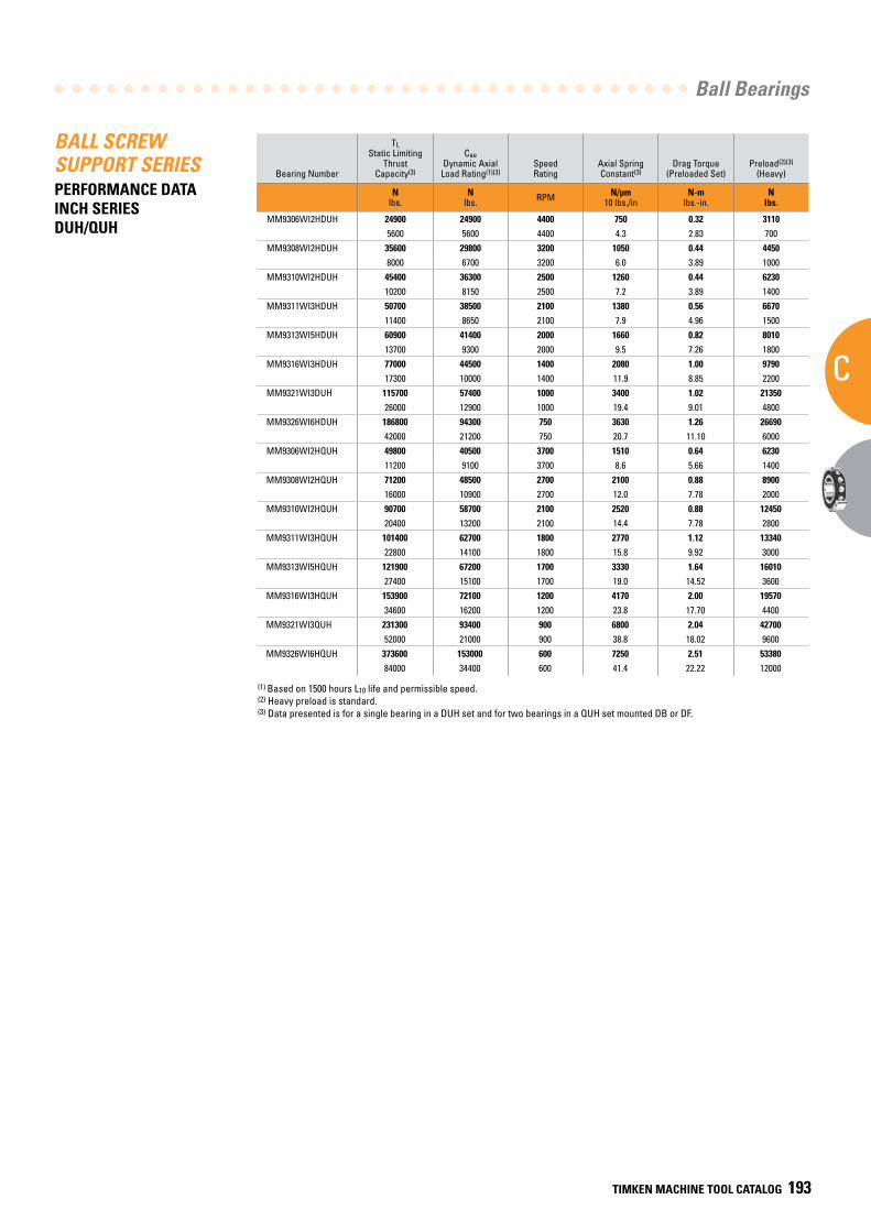
Ball Bearings
C
TIMKEN MACHINE TOOL CATALOG 193
BALL SCREW SUPPORT SERIESPERFORMANCE DATA INCH SERIES DUH/QUH
(1) Based on 1500 hours L10 life and permissible speed.(2) Heavy preload is standard.(3) Data presented is for a single bearing in a DUH set and for two bearings in a QUH set mounted DB or DF.
Bearing Number
TL Static Limiting
Thrust Capacity(3)
CaeDynamic Axial
Load Rating(1)(3)SpeedRating
Axial SpringConstant(3)
Drag Torque(Preloaded Set)
Preload(2)(3)
(Heavy)
Nlbs.
Nlbs. RPM N/µm
10 lbs./inN-m
lbs.-in.N
lbs.
MM9306WI2HDUH 24900 24900 4400 750 0.32 31105600 5600 4400 4.3 2.83 700
MM9308WI2HDUH 35600 29800 3200 1050 0.44 44508000 6700 3200 6.0 3.89 1000
MM9310WI2HDUH 45400 36300 2500 1260 0.44 623010200 8150 2500 7.2 3.89 1400
MM9311WI3HDUH 50700 38500 2100 1380 0.56 667011400 8650 2100 7.9 4.96 1500
MM9313WI5HDUH 60900 41400 2000 1660 0.82 801013700 9300 2000 9.5 7.26 1800
MM9316WI3HDUH 77000 44500 1400 2080 1.00 979017300 10000 1400 11.9 8.85 2200
MM9321WI3DUH 115700 57400 1000 3400 1.02 2135026000 12900 1000 19.4 9.01 4800
MM9326WI6HDUH 186800 94300 750 3630 1.26 2669042000 21200 750 20.7 11.10 6000
MM9306WI2HQUH 49800 40500 3700 1510 0.64 623011200 9100 3700 8.6 5.66 1400
MM9308WI2HQUH 71200 48500 2700 2100 0.88 890016000 10900 2700 12.0 7.78 2000
MM9310WI2HQUH 90700 58700 2100 2520 0.88 1245020400 13200 2100 14.4 7.78 2800
MM9311WI3HQUH 101400 62700 1800 2770 1.12 1334022800 14100 1800 15.8 9.92 3000
MM9313WI5HQUH 121900 67200 1700 3330 1.64 1601027400 15100 1700 19.0 14.52 3600
MM9316WI3HQUH 153900 72100 1200 4170 2.00 1957034600 16200 1200 23.8 17.70 4400
MM9321WI3QUH 231300 93400 900 6800 2.04 4270052000 21000 900 38.8 18.02 9600
MM9326WI6HQUH 373600 153000 600 7250 2.51 5338084000 34400 600 41.4 22.22 12000
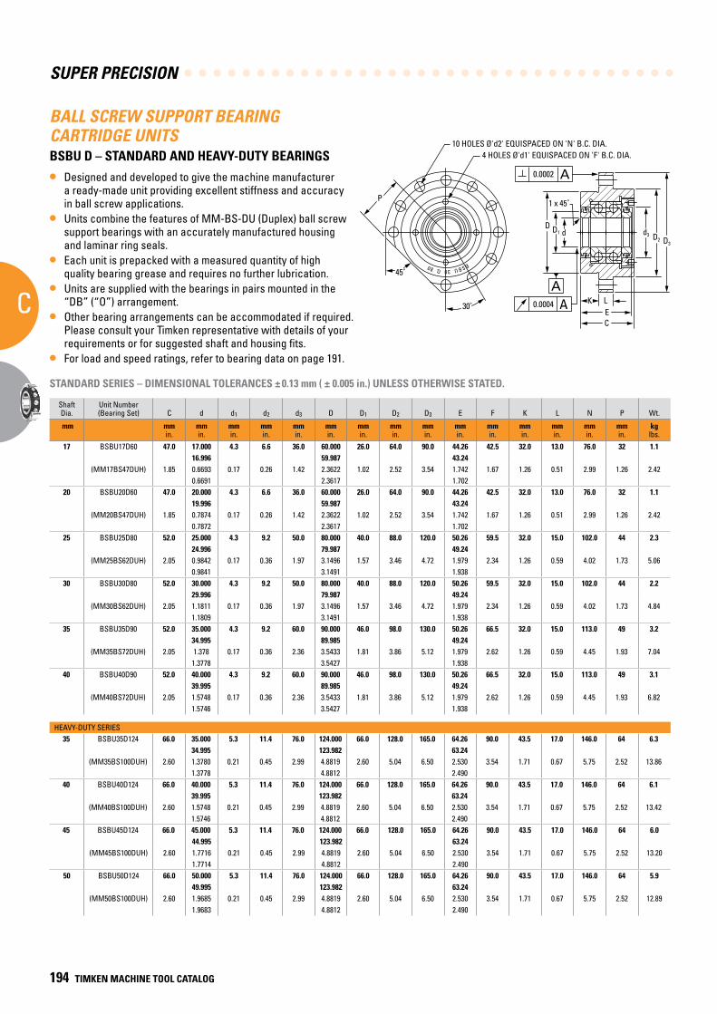
SUPER PRECISION
C
194 TIMKEN MACHINE TOOL CATALOG
d
C
BSBU 30 Q 80
30˚
45˚
P
10 HOLES 'd2' EQUISPACED ON 'N' B.C. DIA.4 HOLES 'd1' EQUISPACED ON 'F' B.C. DIA.
A0.0002
A0.0004
A
D1D
1 x 45˚
D2 D3
d3
ELK
BALL SCREW SUPPORT BEARING CARTRIDGE UNITSBSBU D – STANDARD AND HEAVY-DUTY BEARINGS
• Designed and developed to give the machine manufacturer a ready-made unit providing excellent stiffness and accuracy in ball screw applications.
• Units combine the features of MM-BS-DU (Duplex) ball screw support bearings with an accurately manufactured housing and laminar ring seals.
• Each unit is prepacked with a measured quantity of high quality bearing grease and requires no further lubrication.
• Units are supplied with the bearings in pairs mounted in the “DB” (“O”) arrangement.
• Other bearing arrangements can be accommodated if required. Please consult your Timken representative with details of your requirements or for suggested shaft and housing fits.
• For load and speed ratings, refer to bearing data on page 191.
STANDARD SERIES – DIMENSIONAL TOLERANCES ± 0.13 mm ( ± 0.005 in.) UNLESS OTHERWISE STATED.
ShaftDia.
Unit Number (Bearing Set) C d d1 d2 d3 D D1 D2 D3 E F K L N P Wt.
mm mmin.
mmin.
mmin.
mmin.
mmin.
mmin.
mmin.
mmin.
mmin.
mmin.
mmin.
mmin.
mmin.
mmin.
mmin.
kglbs.
17 BSBU17D60 47.0 17.000 4.3 6.6 36.0 60.000 26.0 64.0 90.0 44.26 42.5 32.0 13.0 76.0 32 1.116.996 59.987 43.24
(MM17BS47DUH) 1.85 0.6693 0.17 0.26 1.42 2.3622 1.02 2.52 3.54 1.742 1.67 1.26 0.51 2.99 1.26 2.420.6691 2.3617 1.702
20 BSBU20D60 47.0 20.000 4.3 6.6 36.0 60.000 26.0 64.0 90.0 44.26 42.5 32.0 13.0 76.0 32 1.119.996 59.987 43.24
(MM20BS47DUH) 1.85 0.7874 0.17 0.26 1.42 2.3622 1.02 2.52 3.54 1.742 1.67 1.26 0.51 2.99 1.26 2.420.7872 2.3617 1.702
25 BSBU25D80 52.0 25.000 4.3 9.2 50.0 80.000 40.0 88.0 120.0 50.26 59.5 32.0 15.0 102.0 44 2.324.996 79.987 49.24
(MM25BS62DUH) 2.05 0.9842 0.17 0.36 1.97 3.1496 1.57 3.46 4.72 1.979 2.34 1.26 0.59 4.02 1.73 5.060.9841 3.1491 1.938
30 BSBU30D80 52.0 30.000 4.3 9.2 50.0 80.000 40.0 88.0 120.0 50.26 59.5 32.0 15.0 102.0 44 2.229.996 79.987 49.24
(MM30BS62DUH) 2.05 1.1811 0.17 0.36 1.97 3.1496 1.57 3.46 4.72 1.979 2.34 1.26 0.59 4.02 1.73 4.841.1809 3.1491 1.938
35 BSBU35D90 52.0 35.000 4.3 9.2 60.0 90.000 46.0 98.0 130.0 50.26 66.5 32.0 15.0 113.0 49 3.234.995 89.985 49.24
(MM35BS72DUH) 2.05 1.378 0.17 0.36 2.36 3.5433 1.81 3.86 5.12 1.979 2.62 1.26 0.59 4.45 1.93 7.041.3778 3.5427 1.938
40 BSBU40D90 52.0 40.000 4.3 9.2 60.0 90.000 46.0 98.0 130.0 50.26 66.5 32.0 15.0 113.0 49 3.139.995 89.985 49.24
(MM40BS72DUH) 2.05 1.5748 0.17 0.36 2.36 3.5433 1.81 3.86 5.12 1.979 2.62 1.26 0.59 4.45 1.93 6.821.5746 3.5427 1.938
HEAVY-DUTY SERIES35 BSBU35D124 66.0 35.000 5.3 11.4 76.0 124.000 66.0 128.0 165.0 64.26 90.0 43.5 17.0 146.0 64 6.3
34.995 123.982 63.24(MM35BS100DUH) 2.60 1.3780 0.21 0.45 2.99 4.8819 2.60 5.04 6.50 2.530 3.54 1.71 0.67 5.75 2.52 13.86
1.3778 4.8812 2.49040 BSBU40D124 66.0 40.000 5.3 11.4 76.0 124.000 66.0 128.0 165.0 64.26 90.0 43.5 17.0 146.0 64 6.1
39.995 123.982 63.24(MM40BS100DUH) 2.60 1.5748 0.21 0.45 2.99 4.8819 2.60 5.04 6.50 2.530 3.54 1.71 0.67 5.75 2.52 13.42
1.5746 4.8812 2.49045 BSBU45D124 66.0 45.000 5.3 11.4 76.0 124.000 66.0 128.0 165.0 64.26 90.0 43.5 17.0 146.0 64 6.0
44.995 123.982 63.24(MM45BS100DUH) 2.60 1.7716 0.21 0.45 2.99 4.8819 2.60 5.04 6.50 2.530 3.54 1.71 0.67 5.75 2.52 13.20
1.7714 4.8812 2.49050 BSBU50D124 66.0 50.000 5.3 11.4 76.0 124.000 66.0 128.0 165.0 64.26 90.0 43.5 17.0 146.0 64 5.9
49.995 123.982 63.24(MM50BS100DUH) 2.60 1.9685 0.21 0.45 2.99 4.8819 2.60 5.04 6.50 2.530 3.54 1.71 0.67 5.75 2.52 12.89
1.9683 4.8812 2.490
10 HOLES Ø'd2' EQUISPACED ON 'N' B.C. DIA.4 HOLES Ø'd1' EQUISPACED ON 'F' B.C. DIA.
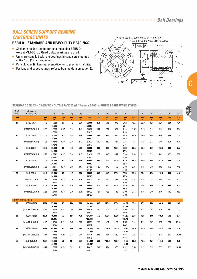
Ball Bearings
C
TIMKEN MACHINE TOOL CATALOG 195
d
C
BSBU 30 Q 80
30˚
45˚
P
10 HOLES 'd2' EQUISPACED ON 'N' B.C. DIA.4 HOLES 'd1' EQUISPACED ON 'F' B.C. DIA.
A0.0002
A0.0004
A
D1D
1 x 45˚
D2 D3
d3
ELK
BALL SCREW SUPPORT BEARING CARTRIDGE UNITS BSBU Q – STANDARD AND HEAVY-DUTY BEARINGS
• Similar in design and features to the series BSBU D except MM-BS-QU Quadruplex bearings are used.
• Units are supplied with the bearings in quad sets mounted in the "DB" ("O") arrangement.
• Consult your Timken representative for suggested shaft fits.• For load and speed ratings, refer to bearing data on page 192.
STANDARD SERIES – DIMENSIONAL TOLERANCES ± 0.13 mm ( ± 0.005 in.) UNLESS OTHERWISE STATED.
ShaftDia.
Unit Number (Bearing Set) C d d1 d2 d3 D D1 D2 D3 E F K L N P Wt.
mm mmin.
mmin.
mmin.
mmin.
mmin.
mmin.
mmin.
mmin.
mmin.
mmin.
mmin.
mmin.
mmin.
mmin.
mmin.
kglbs.
17 BSBU17Q60 77.0 17.000 4.3 6.6 36.0 60.000 26.0 64.0 90.0 74.26 42.5 32.0 13.0 76.0 32.0 1.716.996 59.987 72.74
(MM17BS47QUH) 3.03 0.6693 0.17 0.26 1.42 2.3622 1.02 2.52 3.54 2.924 1.67 1.26 0.51 2.99 1.26 3.740.6690 2.3617 2.864
20 BSBU20Q60 77.0 20.000 4.3 6.6 36.0 60.000 26.0 64.0 90.0 74.26 42.5 32.0 13.0 76.0 32.0 1.719.996 59.987 72.74
(MM20BS47QUH) 3.03 0.7874 0.17 0.26 1.42 2.3622 1.02 2.52 3.54 2.924 1.67 1.26 0.51 2.99 1.26 3.740.7872 2.3617 2.864
25 BSBU25Q80 82.0 25.000 4.3 9.2 50.0 80.000 40.0 88.0 120.0 80.26 59.5 32.0 15.0 102.0 44.0 3.524.996 79.987 78.74
(MM25BS62QUH) 3.23 0.9842 0.17 0.36 1.97 3.1496 1.57 3.46 4.72 3.160 2.34 1.26 0.59 4.02 1.73 7.700.9841 3.1491 3.100
30 BSBU30Q80 82.0 30.000 4.3 9.2 50.0 80.000 40.0 88.0 120.0 80.26 59.5 32.0 15.0 102.0 44.0 3.429.996 79.987 78.74
(MM30BS62QUH) 3.23 1.1811 0.17 0.36 1.97 3.1496 1.57 3.46 4.72 3.160 2.34 1.26 0.59 4.02 1.73 7.481.1809 3.1491 3.100
35 BSBU35Q90 82.0 35.000 4.3 9.2 60.0 90.000 46.0 98.0 130.0 80.26 66.5 32.0 15.0 113.0 49.0 4.634.995 89.985 78.74
(MM35BS72QUH 3.23 1.3780 0.17 0.36 2.36 3.5433 1.81 3.86 5.12 3.160 2.62 1.26 0.59 4.45 1.93 10.121.3778 3.5427 3.100
40 BSBU40Q90 82.0 40.000 4.3 9.2 60.0 90.000 46.0 98.0 130.0 80.26 66.5 32.0 15.0 113.0 49.0 4.539.995 89.985 78.74
(MM40BS72QUH) 3.23 1.5748 0.17 0.36 2.36 3.5433 1.81 3.86 5.12 3.160 2.62 1.26 0.59 4.45 1.93 9.901.5746 3.5427 3.100
HEAVY-DUTY SERIES35 BSBU35Q124 106.0 35.000 5.3 11.4 76.0 124.000 66.0 128.0 165.0 104.26 90.0 43.5 17.0 146.0 64.0 10.1
34.995 123.982 102.74(MM35BS100QUH) 4.17 1.3780 0.21 0.45 2.99 4.8819 2.60 5.04 6.50 4.105 3.54 1.71 0.67 5.75 2.52 22.22
1.3778 4.8812 4.04540 BSBU40Q124 106.0 40.000 5.3 11.4 76.0 124.000 66.0 128.0 165.0 104.26 90.0 43.5 17.0 146.0 64.0 9.7
39.995 123.982 102.74(MM40BS100QUH) 4.17 1.5748 0.21 0.45 2.99 4.8819 2.60 5.04 6.50 4.105 3.54 1.71 0.67 5.75 2.52 21.34
1.5746 4.8812 4.04545 BSBU45Q124 106.0 45.000 5.3 11.4 76.0 124.000 66.0 128.0 165.0 104.26 90.0 43.5 17.0 146.0 64.0 9.5
44.995 123.982 102.74(MM45BS100QUH) 4.17 1.7716 0.21 0.45 2.99 4.8819 2.60 5.04 6.50 4.105 3.54 1.71 0.67 5.75 2.52 20.90
1.7714 4.8812 4.04550 BSBU50Q124 106.0 50.000 5.3 11.4 76.0 124.000 66.0 128.0 165.0 104.26 90.0 43.5 17.0 146.0 64.0 9.3
49.995 123.982 102.74(MM50BS100QUH) 4.17 1.9685 0.21 0.45 2.99 4.8819 2.60 5.04 6.50 4.105 3.54 1.71 0.67 5.75 2.52 20.46
1.9683 4.8812 4.045
10 HOLES Ø'd2' EQUISPACED ON 'N' B.C. DIA.
4 HOLES Ø'd1' EQUISPACED ON 'F' B.C. DIA.4 HOLES Ø'd1' EQUISPACED ON 'F' B.C. DIA.
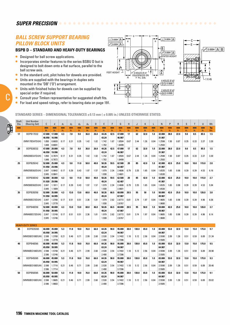
SUPER PRECISION
C
196 TIMKEN MACHINE TOOL CATALOG
A0.0004
B
A0.0004 BA0.0004
A0.0004
A0.0004
A
G G
K
J
N
HH
FOOT HEIGHT 4 HOLES 'd1' EQUISPACED ON
'F' P.C. DIA.
L
CENTER HEIGHTD
CE
d4d
1 X 45�
0.00084 HOLES 'd3'
0.00082 HOLES 'd2'P
SR
HH
TU
A0.0004
B
A0.0004 BA0.0004
A0.0004
A0.0004
A
G G
K
J
N
HH
FOOT HEIGHT 4 HOLES 'd1' EQUISPACED ON
'F' P.C. DIA.
L
CENTER HEIGHTD
CE
d4d
1 X 45�
0.00084 HOLES 'd3'
0.00082 HOLES 'd2'P
SR
HH
TU
BALL SCREW SUPPORT BEARING PILLOW BLOCK UNITSBSPB D – STANDARD AND HEAVY-DUTY BEARINGS
• Designed for ball screw applications.• Incorporates similar features to the series BSBU D but is
designed to bolt down onto a flat surface, parallel to the ball screw axis.
• In the standard unit, pilot holes for dowels are provided.• Units are supplied with the bearings in duplex sets
mounted in the "DB" ("O") arrangement.• Units with finished holes for dowels can be supplied by
special order if required.• Consult your Timken representative for suggested shaft fits.• For load and speed ratings, refer to bearing data on page 191.
Shaft Dia.
Unit Number (Bearing Set) C d d1 d2 d3 d4 D E F G H J K L N P R S T U Wt.
mm mmin.
mmin.
mmin.
mmin.
mmin.
mmin.
mmin.
mmin.
mmin.
mmin.
mmin.
mmin.
mmin.
mmin.
mmin.
mmin.
mmin.
mmin.
mmin.
mmin.
kglbs.
17 BSPB17D32 47.000 17.000 4.3 7.8 9.0 36.0 26.0 44.26 42.5 47.000 17 62 32.0 1.0 32.000 38.0 22.0 9.0 8.5 85.5 1.546.950 16.996 43.24 46.987 31.987
(MM17BS47DUH) 1.850 0.6693 0.17 0.31 0.35 1.42 1.02 1.742 1.67 1.8504 0.67 2.44 1.26 0.04 1.2598 1.50 0.87 0.35 0.33 3.37 3.301.848 0.6691 1.702 1.8499 1.2593
20 BSPB20D32 47.000 20.000 4.3 7.8 9.0 36.0 26.0 44.26 42.5 47.000 17 62 32.0 1.0 32.000 38.0 22.0 9.0 8.5 85.5 1.546.950 19.996 43.24 46.987 31.987
(MM20BS47DUH) 1.850 0.7874 0.17 0.31 0.35 1.42 1.02 1.742 1.67 1.8504 0.67 2.44 1.26 0.04 1.2598 1.50 0.87 0.35 0.33 3.37 3.301.848 0.7872 1.702 1.8499 1.2593
25 BSPB25D42 52.000 25.000 4.3 9.8 11.0 50.0 40.0 50.26 59.5 62.500 20 85 42.0 1.0 42.000 42.0 25.0 10.0 10.0 115.0 2.851.950 24.996 49.24 62.487 41.987
(MM25BS62DUH) 2.047 0.9842 0.17 0.39 0.43 1.97 1.57 1.979 2.34 2.4606 0.79 3.35 1.65 0.04 1.6535 1.65 0.98 0.39 0.39 4.53 6.162.045 0.9841 1.938 2.4601 1.6530
30 BSPB30D42 52.000 30.000 4.3 9.8 11.0 50.0 40.0 50.26 59.5 62.500 20 85 42.0 1.0 42.000 42.0 25.0 10.0 10.0 115.0 2.751.920 29.996 49.24 62.487 41.987
(MM30BS62DUH) 2.047 1.1811 0.17 0.39 0.43 1.97 1.57 1.979 2.34 2.4606 0.79 3.35 1.65 0.04 1.6535 1.65 0.98 0.39 0.39 4.53 5.942.045 1.1809 1.938 2.4601 1.6530
35 BSPB35D50 52.000 35.000 4.3 13.0 13.0 60.0 46.0 50.26 66.5 68.000 20.5 95 50 1.0 50.000 42.0 25.0 10.0 10.0 126.0 3.851.950 34.995 49.24 67.987 49.987
(MM35BS72DUH) 2.047 1.3780 0.17 0.51 0.51 2.36 1.81 1.979 2.62 2.6772 0.81 3.74 1.97 0.04 1.9685 1.65 0.98 0.39 0.39 4.96 8.362.045 1.3778 1.938 2.6767 1.9680
40 BSPB40D50 52.000 40.000 4.3 13.0 13.0 60.0 46.0 50.26 66.5 68.000 20.5 95 50.0 1.0 50.000 42.0 25.0 10.0 10.0 126.0 3.751.950 39.995 49.24 67.987 49.987
(MM40BS72DUH) 2.047 1.5748 0.17 0.51 0.51 2.36 1.81 1.979 2.62 2.6772 0.81 3.74 1.97 0.04 1.9685 1.65 0.98 0.39 0.39 4.96 8.142.045 1.5746 1.938 2.6767 1.9680
HEAVY-DUTY SERIES35 BSPB35D65 66.000 35.000 5.3 11.8 18.0 76.0 66.0 64.26 90.0 95.000 30.0 130.0 65.0 1.0 65.000 53.0 32.0 13.0 15.0 175.0 9.7
65.950 34.995 63.24 94.987 64.987(MM35BS100DUH) 2.598 1.3780 0.21 0.46 0.71 2.99 2.60 2.530 3.54 3.7402 1.18 5.12 2.56 0.04 2.5590 2.09 1.26 0.51 0.59 6.89 21.34
2.596 1.3778 2.490 3.7396 2.558540 BSPB40D65 66.000 40.000 5.3 11.8 18.0 76.0 66.0 64.26 90.0 95.000 30.0 130.0 65.0 1.0 65.000 53.0 32.0 13.0 15.0 175.0 9.5
65.950 39.995 63.24 94.987 64.987(MM40BS100DUH) 2.598 1.5748 0.21 0.46 0.71 2.99 2.60 2.530 3.54 3.7402 1.18 5.12 2.56 0.04 2.5590 2.09 1.26 0.51 0.59 6.89 20.90
2.596 1.5746 2.490 3.7396 2.558545 BSPB45D65 66.000 45.000 5.3 11.8 18.0 76.0 66.0 64.26 90.0 95.000 30.0 130.0 65.0 1.0 65.000 53.0 32.0 13.0 15.0 175.0 9.3
65.950 44.995 63.24 94.987 64.987(MM45BS100DUH) 2.598 1.7716 0.21 0.46 0.71 2.99 2.60 2.530 3.54 3.7402 1.18 5.12 2.56 0.04 2.5590 2.09 1.26 0.51 0.59 6.89 20.46
2.596 1.7714 2.490 3.7396 2.558550 BSPB50D65 66.000 50.000 5.3 11.8 18.0 76.0 66.0 64.26 90.0 95.000 30.0 130.0 65.0 1.0 65.000 53.0 32.0 13.0 15.0 175.0 9.1
65.950 49.995 63.24 94.987 64.987(MM50BS100DUH) 2.598 1.9685 0.21 0.46 0.71 2.99 2.60 2.530 3.54 3.7402 1.18 5.12 2.56 0.04 2.5590 2.09 1.26 0.51 0.59 6.89 20.02
2.596 1.9683 2.490 3.7396 2.5585
STANDARD SERIES – DIMENSIONAL TOLERANCES ± 0.13 mm ( ± 0.005 in.) UNLESS OTHERWISE STATED.
4 HOLES Ø'd1' EQUISPACED ON
'F' P.C. DIA.
FOOT HEIGHT
CENTER HEIGHT
4 HOLES Ø'd3'
2 HOLES Ø'd2'
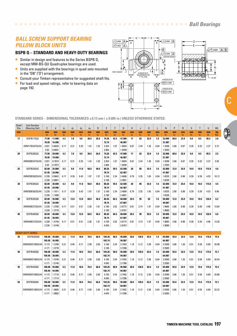
Ball Bearings
C
TIMKEN MACHINE TOOL CATALOG 197
A0.0004
B
A0.0004 BA0.0004
A0.0004
A0.0004
A
G G
K
J
N
HH
FOOT HEIGHT 4 HOLES 'd1' EQUISPACED ON
'F' P.C. DIA.
L
CENTER HEIGHTD
CE
d4d
1 X 45˚
0.0008
4 HOLES 'd3'
0.0008
2 HOLES 'd2'P
SR
HH
TU
BALL SCREW SUPPORT BEARING PILLOW BLOCK UNITSBSPB Q – STANDARD AND HEAVY-DUTY BEARINGS
• Similar in design and features to the Series BSPB D, except MM-BS-QU Quadruplex bearings are used.
• Units are supplied with the bearings in quad sets mounted in the "DB" ("O") arrangement.
• Consult your Timken representative for suggested shaft fits.• For load and speed ratings, refer to bearing data on
page 192.
Shaft Dia.
Unit Number (Bearing Set) C d d1 d2 d3 d4 D E F G H J K L N P R S T U Wt.
mm mmin.
mmin.
mmin.
mmin.
mmin.
mmin.
mmin.
mmin.
mmin.
mmin.
mmin.
mmin.
mmin.
mmin.
mmin.
mmin.
mmin.
mmin.
mmin.
mmin.
kglbs.
17 BSPB17D32 47.000 17.000 4.3 7.8 9.0 36.0 26.0 44.26 42.5 47.000 17 62 32.0 1.0 32.000 38.0 22.0 9.0 8.5 85.5 1.546.950 16.996 43.24 46.987 31.987
(MM17BS47DUH) 1.850 0.6693 0.17 0.31 0.35 1.42 1.02 1.742 1.67 1.8504 0.67 2.44 1.26 0.04 1.2598 1.50 0.87 0.35 0.33 3.37 3.301.848 0.6691 1.702 1.8499 1.2593
20 BSPB20D32 47.000 20.000 4.3 7.8 9.0 36.0 26.0 44.26 42.5 47.000 17 62 32.0 1.0 32.000 38.0 22.0 9.0 8.5 85.5 1.546.950 19.996 43.24 46.987 31.987
(MM20BS47DUH) 1.850 0.7874 0.17 0.31 0.35 1.42 1.02 1.742 1.67 1.8504 0.67 2.44 1.26 0.04 1.2598 1.50 0.87 0.35 0.33 3.37 3.301.848 0.7872 1.702 1.8499 1.2593
25 BSPB25D42 52.000 25.000 4.3 9.8 11.0 50.0 40.0 50.26 59.5 62.500 20 85 42.0 1.0 42.000 42.0 25.0 10.0 10.0 115.0 2.851.950 24.996 49.24 62.487 41.987
(MM25BS62DUH) 2.047 0.9842 0.17 0.39 0.43 1.97 1.57 1.979 2.34 2.4606 0.79 3.35 1.65 0.04 1.6535 1.65 0.98 0.39 0.39 4.53 6.162.045 0.9841 1.938 2.4601 1.6530
30 BSPB30D42 52.000 30.000 4.3 9.8 11.0 50.0 40.0 50.26 59.5 62.500 20 85 42.0 1.0 42.000 42.0 25.0 10.0 10.0 115.0 2.751.920 29.996 49.24 62.487 41.987
(MM30BS62DUH) 2.047 1.1811 0.17 0.39 0.43 1.97 1.57 1.979 2.34 2.4606 0.79 3.35 1.65 0.04 1.6535 1.65 0.98 0.39 0.39 4.53 5.942.045 1.1809 1.938 2.4601 1.6530
35 BSPB35D50 52.000 35.000 4.3 13.0 13.0 60.0 46.0 50.26 66.5 68.000 20.5 95 50 1.0 50.000 42.0 25.0 10.0 10.0 126.0 3.851.950 34.995 49.24 67.987 49.987
(MM35BS72DUH) 2.047 1.3780 0.17 0.51 0.51 2.36 1.81 1.979 2.62 2.6772 0.81 3.74 1.97 0.04 1.9685 1.65 0.98 0.39 0.39 4.96 8.362.045 1.3778 1.938 2.6767 1.9680
40 BSPB40D50 52.000 40.000 4.3 13.0 13.0 60.0 46.0 50.26 66.5 68.000 20.5 95 50.0 1.0 50.000 42.0 25.0 10.0 10.0 126.0 3.751.950 39.995 49.24 67.987 49.987
(MM40BS72DUH) 2.047 1.5748 0.17 0.51 0.51 2.36 1.81 1.979 2.62 2.6772 0.81 3.74 1.97 0.04 1.9685 1.65 0.98 0.39 0.39 4.96 8.142.045 1.5746 1.938 2.6767 1.9680
HEAVY-DUTY SERIES35 BSPB35D65 66.000 35.000 5.3 11.8 18.0 76.0 66.0 64.26 90.0 95.000 30.0 130.0 65.0 1.0 65.000 53.0 32.0 13.0 15.0 175.0 9.7
65.950 34.995 63.24 94.987 64.987(MM35BS100DUH) 2.598 1.3780 0.21 0.46 0.71 2.99 2.60 2.530 3.54 3.7402 1.18 5.12 2.56 0.04 2.5590 2.09 1.26 0.51 0.59 6.89 21.34
2.596 1.3778 2.490 3.7396 2.558540 BSPB40D65 66.000 40.000 5.3 11.8 18.0 76.0 66.0 64.26 90.0 95.000 30.0 130.0 65.0 1.0 65.000 53.0 32.0 13.0 15.0 175.0 9.5
65.950 39.995 63.24 94.987 64.987(MM40BS100DUH) 2.598 1.5748 0.21 0.46 0.71 2.99 2.60 2.530 3.54 3.7402 1.18 5.12 2.56 0.04 2.5590 2.09 1.26 0.51 0.59 6.89 20.90
2.596 1.5746 2.490 3.7396 2.558545 BSPB45D65 66.000 45.000 5.3 11.8 18.0 76.0 66.0 64.26 90.0 95.000 30.0 130.0 65.0 1.0 65.000 53.0 32.0 13.0 15.0 175.0 9.3
65.950 44.995 63.24 94.987 64.987(MM45BS100DUH) 2.598 1.7716 0.21 0.46 0.71 2.99 2.60 2.530 3.54 3.7402 1.18 5.12 2.56 0.04 2.5590 2.09 1.26 0.51 0.59 6.89 20.46
2.596 1.7714 2.490 3.7396 2.558550 BSPB50D65 66.000 50.000 5.3 11.8 18.0 76.0 66.0 64.26 90.0 95.000 30.0 130.0 65.0 1.0 65.000 53.0 32.0 13.0 15.0 175.0 9.1
65.950 49.995 63.24 94.987 64.987(MM50BS100DUH) 2.598 1.9685 0.21 0.46 0.71 2.99 2.60 2.530 3.54 3.7402 1.18 5.12 2.56 0.04 2.5590 2.09 1.26 0.51 0.59 6.89 20.02
2.596 1.9683 2.490 3.7396 2.5585
Shaft Dia.
Unit Number (Bearing Set) C d d1 d2 d3 d4 D E F G H J K L N P R S T U Wt.
mm mmin.
mmin.
mmin.
mmin.
mmin.
mmin.
mmin.
mmin.
mmin.
mmin.
mmin.
mmin.
mmin.
mmin.
mmin.
mmin.
mmin.
mmin.
mmin.
mmin.
kglbs.
17 BSPB17Q32 77.00 17.000 4.3 7.8 9.0 36.0 26.0 74.26 42.5 47.000 17 62 32.0 1.0 32.000 68.0 22.0 9.0 8.5 85.5 2.676.95 16.996 72.74 46.987 31.987
(MM17BS47QUH) 3.031 0.6693 0.17 0.31 0.35 1.42 1.02 2.924 1.67 1.8504 0.67 2.44 1.26 0.04 1.2598 2.68 0.87 0.35 0.33 3.37 5.723.03 0.6691 2.864 1.8499 1.2593
20 BSPB20Q32 77.00 20.000 4.3 7.8 9.0 36.0 26.0 74.26 42.5 47.000 17 62 32.0 1.0 32.000 68.0 22.0 9.0 8.5 85.5 2.576.95 19.996 72.74 46.987 31.987
(MM20BS47QUH) 3.031 0.7874 0.17 0.31 0.35 1.42 1.02 2.924 1.67 1.8504 0.67 2.44 1.26 0.04 1.2598 2.68 0.87 0.35 0.33 3.37 5.503.03 0.7872 2.864 1.8499 1.2593
25 BSPB25Q42 82.00 25.000 4.3 9.8 11.0 50.0 40.0 80.26 59.5 62.500 20 85 42.0 1.0 42.000 72.0 25.0 10.0 10.0 115.0 4.681.95 24.996 78.74 62.487 41.987
(MM25BS62QUH) 3.228 0.9842 0.17 0.39 0.43 1.97 1.57 3.160 2.34 2.4606 0.79 3.35 1.65 0.04 1.6535 2.68 0.98 0.39 0.39 4.53 10.123.226 0.9841 3.100 2.4601 1.6530
30 BSPB30Q42 82.00 30.000 4.3 9.8 11.0 50.0 40.0 80.26 59.5 62.500 20 85 42.0 1.0 42.000 72.0 25.0 10.0 10.0 115.0 4.581.95 29.996 78.74 62.487 41.987
(MM30BS62QUH) 3.228 1.1811 0.17 0.39 0.43 1.97 1.57 3.160 2.34 2.4606 0.79 3.35 1.65 0.04 1.6535 2.68 0.98 0.39 0.39 4.53 9.903.226 1.1809 3.100 2.4601 1.6530
35 BSPB35Q50 82.00 35.000 4.3 13.0 13.0 60.0 46.0 80.26 66.5 68.000 20.5 95 50 1.0 50.000 72.0 25.0 10.0 10.0 126.0 6.281.95 34.995 78.74 67.987 49.987
(MM35BS72QUH) 3.228 1.3780 0.17 0.51 0.51 2.36 1.81 3.160 2.62 2.6772 0.81 3.74 1.97 0.04 1.9685 2.68 0.98 0.39 0.39 4.96 13.643.226 1.3778 3.100 2.6767 1.9680
40 BSPB40Q50 82.00 40.000 4.3 13.0 13.0 60.0 46.0 80.26 66.5 68.000 20.5 95 50.0 1.0 50.000 72.0 25.0 10.0 10.0 126.0 6.081.95 39.995 78.74 67.987 49.987
(MM40BS72QUH) 3.228 1.5748 0.17 0.51 0.51 2.36 1.81 4.105 2.62 2.6772 0.81 3.74 1.97 0.04 1.9685 2.68 0.98 0.39 0.39 4.96 13.203.226 1.5746 4.045 2.6767 1.9680
HEAVY-DUTY SERIES35 BSPB35D65 106.00 35.000 5.3 11.8 18.0 76.0 66.0 104.26 90.0 95.000 30.0 130.0 65.0 1.0 65.000 93.0 32.0 13.0 15.0 175.0 15.9
105.95 34.995 102.74 94.987 64.987(MM35BS100QUH) 4.173 1.3780 0.21 0.46 0.71 2.99 2.60 3.160 3.54 3.7402 1.18 5.12 2.56 0.04 2.5590 3.66 1.26 0.51 0.59 6.89 34.98
4.171 1.3778 3.100 3.7396 2.558540 BSPB40Q65 106.00 40.000 5.3 11.8 18.0 76.0 66.0 104.26 90.0 95.000 30.0 130.0 65.0 1.0 65.000 93.0 32.0 13.0 15.0 175.0 15.7
105.95 39.995 102.74 94.987 64.987(MM40BS100QUH) 4.173 1.5748 0.21 0.46 0.71 2.99 2.60 4.105 3.54 3.7402 1.18 5.12 2.56 0.04 2.5590 3.66 1.26 0.51 0.59 6.89 34.54
4.171 1.5746 4.045 3.7396 2.558545 BSPB45Q65 106.00 45.000 5.3 11.8 18.0 76.0 66.0 104.26 90.0 95.000 30.0 130.0 65.0 1.0 65.000 93.0 32.0 13.0 15.0 175.0 15.4
105.95 44.995 102.74 94.987 64.987(MM45BS100QUH) 4.173 1.7716 0.21 0.46 0.71 2.99 2.60 4.105 3.54 3.7402 1.18 5.12 2.56 0.04 2.5590 3.66 1.26 0.51 0.59 6.89 33.88
4.171 1.7714 4.045 3.7396 2.558550 BSPB50Q65 106.00 50.000 5.3 11.8 18.0 76.0 66.0 104.26 90.0 95.000 30.0 130.0 65.0 1.0 65.000 93.0 32.0 13.0 15.0 175.0 15.1
105.95 49.995 102.74 94.987 64.987(MM50BS100QUH) 4.173 1.9685 0.21 0.46 0.71 2.99 2.60 4.105 3.54 3.7402 1.18 5.12 2.56 0.04 2.5590 3.66 1.26 0.51 0.59 6.89 33.22
4.171 1.9683 4.045 3.7396 2.5585
STANDARD SERIES – DIMENSIONAL TOLERANCES ± 0.13 mm ( ± 0.005 in.) UNLESS OTHERWISE STATED.
A0.0004
B
A0.0004 BA0.0004
A0.0004
A0.0004
A
G G
K
J
N
HH
FOOT HEIGHT 4 HOLES 'd1' EQUISPACED ON
'F' P.C. DIA.
L
CENTER HEIGHTD
CE
d4d
1 X 45˚
0.0008
4 HOLES 'd3'
0.0008
2 HOLES 'd2'P
SR
HH
TU
4 HOLES Ø'd1' EQUISPACED ON
'F' P.C. DIA.
FOOT HEIGHT
CENTER HEIGHT
4 HOLES Ø'd3'
2 HOLES Ø'd2'
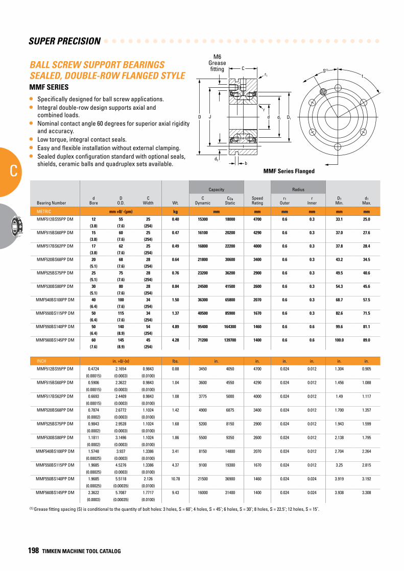
SUPER PRECISION
C
198 TIMKEN MACHINE TOOL CATALOG
BALL SCREW SUPPORT BEARINGS SEALED, DOUBLE-ROW FLANGED STYLE MMF SERIES
• Specifically designed for ball screw applications.• Integral double-row design supports axial and
combined loads.• Nominal contact angle 60 degrees for superior axial rigidity
and accuracy.• Low torque, integral contact seals.• Easy and flexible installation without external clamping.• Sealed duplex configuration standard with optional seals,
shields, ceramic balls and quadruplex sets available.
Bearing Numberd
BoreD
O.D.C
Width Wt.
Capacity RadiusSuggested
Shoulder Dia.d2
BoltDia. Holes
b GrooveWidth
J Bolt CircleDiameter
t Hole
Spacing
Stiffness
CDynamic
COaStatic
Speed Rating
r1Outer
rInner
D1Min.
d1Max. Housing Shaft Axial Radial
InertiaMoment Preload
METRIC mm +0/ -(µm) kg mm mm mm mm mm mm mm mm mm Qty. mm mm Degrees N/µm N/µm kg cm2 N
MMF512BS55PP DM 12 55 25 0.40 15300 18000 4700 0.6 0.3 33.1 25.0 32.0 19.0 6.5 3 3 42 120 380 60 0.062 645(3.8) (7.6) (254)
MMF515BS60PP DM 15 60 25 0.47 16100 20200 4290 0.6 0.3 37.0 27.6 34.5 21.5 6.5 3 3 46 120 400 65 0.076 670(3.8) (7.6) (254)
MMF517BS62PP DM 17 62 25 0.49 16800 22200 4000 0.6 0.3 37.8 28.4 36.5 23.5 6.5 3 3 48 120 450 72 0.097 780(3.8) (7.6) (254)
MMF520BS68PP DM 20 68 28 0.64 21800 30600 3400 0.6 0.3 43.2 34.5 42.5 27.5 6.5 4 3 53 90 650 103 0.212 1780(5.1) (7.6) (254)
MMF525BS75PP DM 25 75 28 0.76 23200 36200 2900 0.6 0.3 49.5 40.6 48.0 33.5 6.5 4 3 58 90 750 118 0.415 2000(5.1) (7.6) (254)
MMF530BS80PP DM 30 80 28 0.84 24500 41500 2600 0.6 0.3 54.3 45.6 53.5 38.5 6.5 6 3 63 60 860 135 0.6 2335(5.1) (7.6) (254)
MMF540BS100PP DM 40 100 34 1.50 36300 65800 2070 0.6 0.3 68.7 57.5 67.0 49.0 8.5 4 3 80 90 1000 160 1.728 2780(6.4) (7.6) (254)
MMF550BS115PP DM 50 115 34 1.37 40500 85900 1670 0.6 0.3 82.6 71.5 81.0 63.0 8.5 6 3 94 60 1250 200 4.288 3335(6.4) (7.6) (254)
MMF550BS140PP DM 50 140 54 4.89 95400 164300 1460 0.6 0.6 99.6 81.1 98.5 66.0 10.5 12 3 113 30 1400 220 20.94 6784(6.4) (8.9) (254)
MMF560BS145PP DM 60 145 45 4.28 71200 139700 1400 0.6 0.6 100.0 89.0 98.0 72.0 8.5 8 3 120 45 1300 210 10.184 4225(7.6) (8.9) (254)
INCH in. +0/-(x) lbs. in. in. in. in. in. in. in. in. in. Qty. in. in. Degrees 106 lb/in. 106 lb/in. lb in,2 lbs.
MMF512BS55PP DM 0.4724 2.1654 0.9843 0.88 3450 4050 4700 0.024 0.012 1.304 0.905 1.26 0.748 0.256 3 0.118 1.654 120 2.17132 0.34284 0.021186466 145
(0.00015) (0.0003) (0.0100)MMF515BS60PP DM 0.5906 2.3622 0.9843 1.04 3600 4550 4290 0.024 0.012 1.456 1.088 1.358 0.846 0.256 3 0.118 1.811 120 2.2856 0.37141 0.025970506 150
(0.00015) (0.0003) (0.0100)MMF517BS62PP DM 0.6693 2.4409 0.9843 1.08 3775 5000 4000 0.024 0.012 1.49 1.117 1.437 0.925 0.256 3 0.118 1.89 120 2.5713 0.411408 0.033146567 175
(0.00015) (0.0003) (0.0100)MMF520BS68PP DM 0.7874 2.6772 1.1024 1.42 4900 6875 3400 0.024 0.012 1.700 1.357 1.673 1.083 0.256 4 0.118 2.087 90 3.7141 0.588542 0.072444044 400
(0.0002) (0.0003) (0.0100)MMF525BS75PP DM 0.9843 2.9528 1.1024 1.68 5200 8150 2900 0.024 0.012 1.943 1.599 1.890 1.319 0.256 4 0.118 2.283 90 4.2855 0.674252 0.141812634 450
(0.0002) (0.0003) (0.0100)MMF530BS80PP DM 1.1811 3.1496 1.1024 1.86 5500 9350 2600 0.024 0.012 2.138 1.795 2.106 1.516 0.256 6 0.118 2.48 60 4.91404 0.77139 0.205030314 525
(0.0002) (0.0003) (0.0100)MMF540BS100PP DM 1.5748 3.937 1.3386 3.41 8150 14800 2070 0.024 0.012 2.704 2.264 2.638 1.929 0.335 4 0.118 3.15 90 5.714 0.91424 0.590487304 625
(0.00025) (0.0003) (0.0100)MMF550BS115PP DM 1.9685 4.5276 1.3386 4.37 9100 19300 1670 0.024 0.012 3.25 2.815 3.189 2.408 0.335 6 0.118 3.701 60 7.1425 1.1428 1.465283311 750
(0.00025) (0.0003) (0.0100)MMF550BS140PP DM 1.9685 5.5118 2.126 10.78 21500 36900 1460 0.024 0.024 3.919 3.192 3.878 2.598 0.413 12 0.118 4.449 30 7.9996 1.25708 7.155557959 1525
(0.00025) (0.00035) (0.0100)MMF560BS145PP DM 2.3622 5.7087 1.7717 9.43 16000 31400 1400 0.024 0.024 3.938 3.308 3.858 2.835 0.335 8 0.118 4.724 45 7.4282 1.19994 3.480047863 950
(0.0003) (0.00035) (0.0100)
MMF Series Flanged
t
MMF Series Flanged
D1d1dr
C
D
r1
J
bd2
M6Greasefitting S(1)
(1) Grease fitting spacing (S) is conditional to the quantity of bolt holes: 3 holes, S = 60˚; 4 holes, S = 45˚; 6 holes, S = 30˚; 8 holes, S = 22.5˚; 12 holes, S = 15˚.
M6Greasefitting
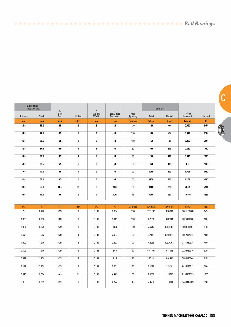
Ball Bearings
C
TIMKEN MACHINE TOOL CATALOG 199
Bearing Numberd
BoreD
O.D.C
Width Wt.
Capacity RadiusSuggested
Shoulder Dia.d2
BoltDia. Holes
b GrooveWidth
J Bolt CircleDiameter
t Hole
Spacing
Stiffness
CDynamic
COaStatic
Speed Rating
r1Outer
rInner
D1Min.
d1Max. Housing Shaft Axial Radial
InertiaMoment Preload
METRIC mm +0/ -(µm) kg mm mm mm mm mm mm mm mm mm Qty. mm mm Degrees N/µm N/µm kg cm2 N
MMF512BS55PP DM 12 55 25 0.40 15300 18000 4700 0.6 0.3 33.1 25.0 32.0 19.0 6.5 3 3 42 120 380 60 0.062 645(3.8) (7.6) (254)
MMF515BS60PP DM 15 60 25 0.47 16100 20200 4290 0.6 0.3 37.0 27.6 34.5 21.5 6.5 3 3 46 120 400 65 0.076 670(3.8) (7.6) (254)
MMF517BS62PP DM 17 62 25 0.49 16800 22200 4000 0.6 0.3 37.8 28.4 36.5 23.5 6.5 3 3 48 120 450 72 0.097 780(3.8) (7.6) (254)
MMF520BS68PP DM 20 68 28 0.64 21800 30600 3400 0.6 0.3 43.2 34.5 42.5 27.5 6.5 4 3 53 90 650 103 0.212 1780(5.1) (7.6) (254)
MMF525BS75PP DM 25 75 28 0.76 23200 36200 2900 0.6 0.3 49.5 40.6 48.0 33.5 6.5 4 3 58 90 750 118 0.415 2000(5.1) (7.6) (254)
MMF530BS80PP DM 30 80 28 0.84 24500 41500 2600 0.6 0.3 54.3 45.6 53.5 38.5 6.5 6 3 63 60 860 135 0.6 2335(5.1) (7.6) (254)
MMF540BS100PP DM 40 100 34 1.50 36300 65800 2070 0.6 0.3 68.7 57.5 67.0 49.0 8.5 4 3 80 90 1000 160 1.728 2780(6.4) (7.6) (254)
MMF550BS115PP DM 50 115 34 1.37 40500 85900 1670 0.6 0.3 82.6 71.5 81.0 63.0 8.5 6 3 94 60 1250 200 4.288 3335(6.4) (7.6) (254)
MMF550BS140PP DM 50 140 54 4.89 95400 164300 1460 0.6 0.6 99.6 81.1 98.5 66.0 10.5 12 3 113 30 1400 220 20.94 6784(6.4) (8.9) (254)
MMF560BS145PP DM 60 145 45 4.28 71200 139700 1400 0.6 0.6 100.0 89.0 98.0 72.0 8.5 8 3 120 45 1300 210 10.184 4225(7.6) (8.9) (254)
INCH in. +0/-(x) lbs. in. in. in. in. in. in. in. in. in. Qty. in. in. Degrees 106 lb/in. 106 lb/in. lb in,2 lbs.
MMF512BS55PP DM 0.4724 2.1654 0.9843 0.88 3450 4050 4700 0.024 0.012 1.304 0.905 1.26 0.748 0.256 3 0.118 1.654 120 2.17132 0.34284 0.021186466 145
(0.00015) (0.0003) (0.0100)MMF515BS60PP DM 0.5906 2.3622 0.9843 1.04 3600 4550 4290 0.024 0.012 1.456 1.088 1.358 0.846 0.256 3 0.118 1.811 120 2.2856 0.37141 0.025970506 150
(0.00015) (0.0003) (0.0100)MMF517BS62PP DM 0.6693 2.4409 0.9843 1.08 3775 5000 4000 0.024 0.012 1.49 1.117 1.437 0.925 0.256 3 0.118 1.89 120 2.5713 0.411408 0.033146567 175
(0.00015) (0.0003) (0.0100)MMF520BS68PP DM 0.7874 2.6772 1.1024 1.42 4900 6875 3400 0.024 0.012 1.700 1.357 1.673 1.083 0.256 4 0.118 2.087 90 3.7141 0.588542 0.072444044 400
(0.0002) (0.0003) (0.0100)MMF525BS75PP DM 0.9843 2.9528 1.1024 1.68 5200 8150 2900 0.024 0.012 1.943 1.599 1.890 1.319 0.256 4 0.118 2.283 90 4.2855 0.674252 0.141812634 450
(0.0002) (0.0003) (0.0100)MMF530BS80PP DM 1.1811 3.1496 1.1024 1.86 5500 9350 2600 0.024 0.012 2.138 1.795 2.106 1.516 0.256 6 0.118 2.48 60 4.91404 0.77139 0.205030314 525
(0.0002) (0.0003) (0.0100)MMF540BS100PP DM 1.5748 3.937 1.3386 3.41 8150 14800 2070 0.024 0.012 2.704 2.264 2.638 1.929 0.335 4 0.118 3.15 90 5.714 0.91424 0.590487304 625
(0.00025) (0.0003) (0.0100)MMF550BS115PP DM 1.9685 4.5276 1.3386 4.37 9100 19300 1670 0.024 0.012 3.25 2.815 3.189 2.408 0.335 6 0.118 3.701 60 7.1425 1.1428 1.465283311 750
(0.00025) (0.0003) (0.0100)MMF550BS140PP DM 1.9685 5.5118 2.126 10.78 21500 36900 1460 0.024 0.024 3.919 3.192 3.878 2.598 0.413 12 0.118 4.449 30 7.9996 1.25708 7.155557959 1525
(0.00025) (0.00035) (0.0100)MMF560BS145PP DM 2.3622 5.7087 1.7717 9.43 16000 31400 1400 0.024 0.024 3.938 3.308 3.858 2.835 0.335 8 0.118 4.724 45 7.4282 1.19994 3.480047863 950
(0.0003) (0.00035) (0.0100)
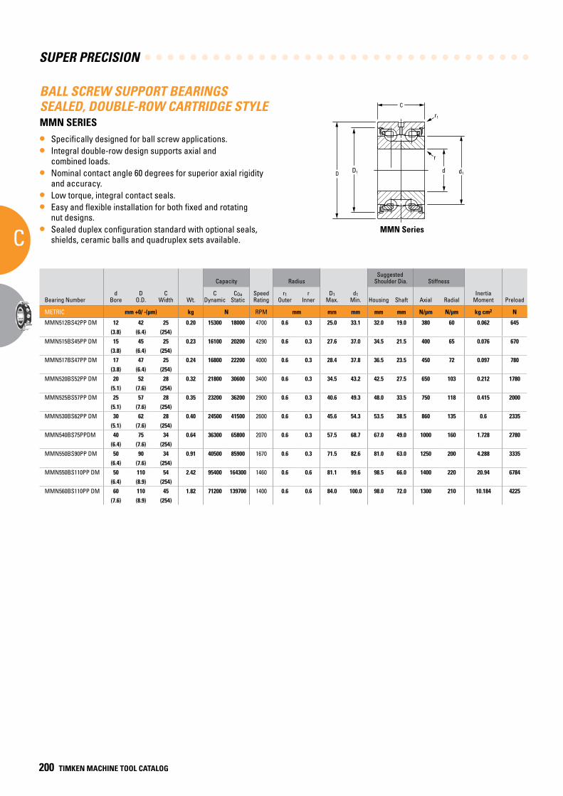
SUPER PRECISION
C
200 TIMKEN MACHINE TOOL CATALOG
MMN Series
C
d d1D D1
r
r1
BALL SCREW SUPPORT BEARINGS SEALED, DOUBLE-ROW CARTRIDGE STYLE MMN SERIES
• Specifically designed for ball screw applications.• Integral double-row design supports axial and
combined loads.• Nominal contact angle 60 degrees for superior axial rigidity
and accuracy.• Low torque, integral contact seals.• Easy and flexible installation for both fixed and rotating
nut designs.• Sealed duplex configuration standard with optional seals,
shields, ceramic balls and quadruplex sets available.MMN Series
Bearing Numberd
BoreD
O.D.C
Width Wt.
Capacity RadiusSuggested
Shoulder Dia. Stiffness
CDynamic
COaStatic
Speed Rating
r1Outer
rInner
D1Max.
d1Min. Housing Shaft Axial Radial
Inertia Moment Preload
METRIC mm +0/ -(µm) kg N RPM mm mm mm mm mm N/µm N/µm kg cm2 N
MMN512BS42PP DM 12 42 25 0.20 15300 18000 4700 0.6 0.3 25.0 33.1 32.0 19.0 380 60 0.062 645(3.8) (6.4) (254)
MMN515BS45PP DM 15 45 25 0.23 16100 20200 4290 0.6 0.3 27.6 37.0 34.5 21.5 400 65 0.076 670(3.8) (6.4) (254)
MMN517BS47PP DM 17 47 25 0.24 16800 22200 4000 0.6 0.3 28.4 37.8 36.5 23.5 450 72 0.097 780(3.8) (6.4) (254)
MMN520BS52PP DM 20 52 28 0.32 21800 30600 3400 0.6 0.3 34.5 43.2 42.5 27.5 650 103 0.212 1780(5.1) (7.6) (254)
MMN525BS57PP DM 25 57 28 0.35 23200 36200 2900 0.6 0.3 40.6 49.3 48.0 33.5 750 118 0.415 2000(5.1) (7.6) (254)
MMN530BS62PP DM 30 62 28 0.40 24500 41500 2600 0.6 0.3 45.6 54.3 53.5 38.5 860 135 0.6 2335(5.1) (7.6) (254)
MMN540BS75PPDM 40 75 34 0.64 36300 65800 2070 0.6 0.3 57.5 68.7 67.0 49.0 1000 160 1.728 2780(6.4) (7.6) (254)
MMN550BS90PP DM 50 90 34 0.91 40500 85900 1670 0.6 0.3 71.5 82.6 81.0 63.0 1250 200 4.288 3335(6.4) (7.6) (254)
MMN550BS110PP DM 50 110 54 2.42 95400 164300 1460 0.6 0.6 81.1 99.6 98.5 66.0 1400 220 20.94 6784(6.4) (8.9) (254)
MMN560BS110PP DM 60 110 45 1.82 71200 139700 1400 0.6 0.6 84.0 100.0 98.0 72.0 1300 210 10.184 4225(7.6) (8.9) (254)
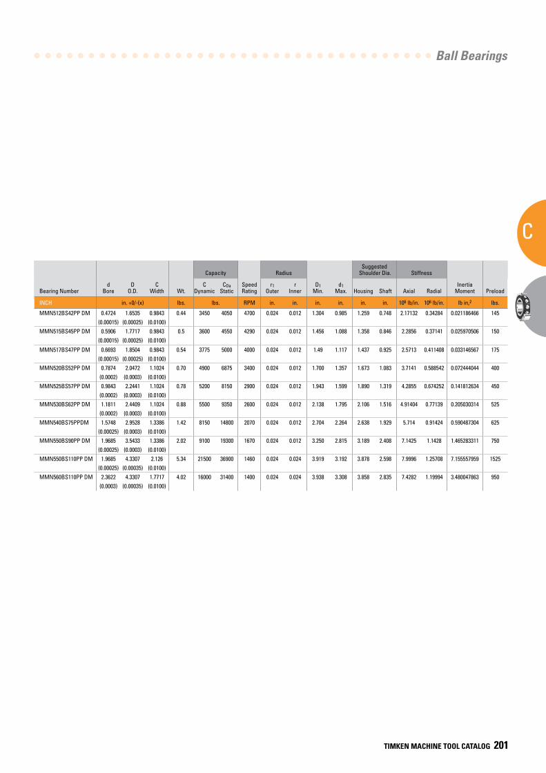
Ball Bearings
C
TIMKEN MACHINE TOOL CATALOG 201
Bearing Numberd
BoreD
O.D.C
Width Wt.
Capacity RadiusSuggested
Shoulder Dia. Stiffness
CDynamic
COaStatic
Speed Rating
r1Outer
rInner
D1Min.
d1Max. Housing Shaft Axial Radial
Inertia Moment Preload
INCH in. +0/-(x) lbs. lbs. RPM in. in. in. in. in. in. 106 lb/in. 106 lb/in. lb in,2 lbs.
MMN512BS42PP DM 0.4724 1.6535 0.9843 0.44 3450 4050 4700 0.024 0.012 1.304 0.985 1.259 0.748 2.17132 0.34284 0.021186466 145(0.00015) (0.00025) (0.0100)
MMN515BS45PP DM 0.5906 1.7717 0.9843 0.5 3600 4550 4290 0.024 0.012 1.456 1.088 1.358 0.846 2.2856 0.37141 0.025970506 150(0.00015) (0.00025) (0.0100)
MMN517BS47PP DM 0.6693 1.8504 0.9843 0.54 3775 5000 4000 0.024 0.012 1.49 1.117 1.437 0.925 2.5713 0.411408 0.033146567 175(0.00015) (0.00025) (0.0100)
MMN520BS52PP DM 0.7874 2.0472 1.1024 0.70 4900 6875 3400 0.024 0.012 1.700 1.357 1.673 1.083 3.7141 0.588542 0.072444044 400(0.0002) (0.0003) (0.0100)
MMN525BS57PP DM 0.9843 2.2441 1.1024 0.78 5200 8150 2900 0.024 0.012 1.943 1.599 1.890 1.319 4.2855 0.674252 0.141812634 450(0.0002) (0.0003) (0.0100)
MMN530BS62PP DM 1.1811 2.4409 1.1024 0.88 5500 9350 2600 0.024 0.012 2.138 1.795 2.106 1.516 4.91404 0.77139 0.205030314 525(0.0002) (0.0003) (0.0100)
MMN540BS75PPDM 1.5748 2.9528 1.3386 1.42 8150 14800 2070 0.024 0.012 2.704 2.264 2.638 1.929 5.714 0.91424 0.590487304 625(0.00025) (0.0003) (0.0100)
MMN550BS90PP DM 1.9685 3.5433 1.3386 2.02 9100 19300 1670 0.024 0.012 3.250 2.815 3.189 2.408 7.1425 1.1428 1.465283311 750(0.00025) (0.0003) (0.0100)
MMN550BS110PP DM 1.9685 4.3307 2.126 5.34 21500 36900 1460 0.024 0.024 3.919 3.192 3.878 2.598 7.9996 1.25708 7.155557959 1525(0.00025) (0.00035) (0.0100)
MMN560BS110PP DM 2.3622 4.3307 1.7717 4.02 16000 31400 1400 0.024 0.024 3.938 3.308 3.858 2.835 7.4282 1.19994 3.480047863 950(0.0003) (0.00035) (0.0100)
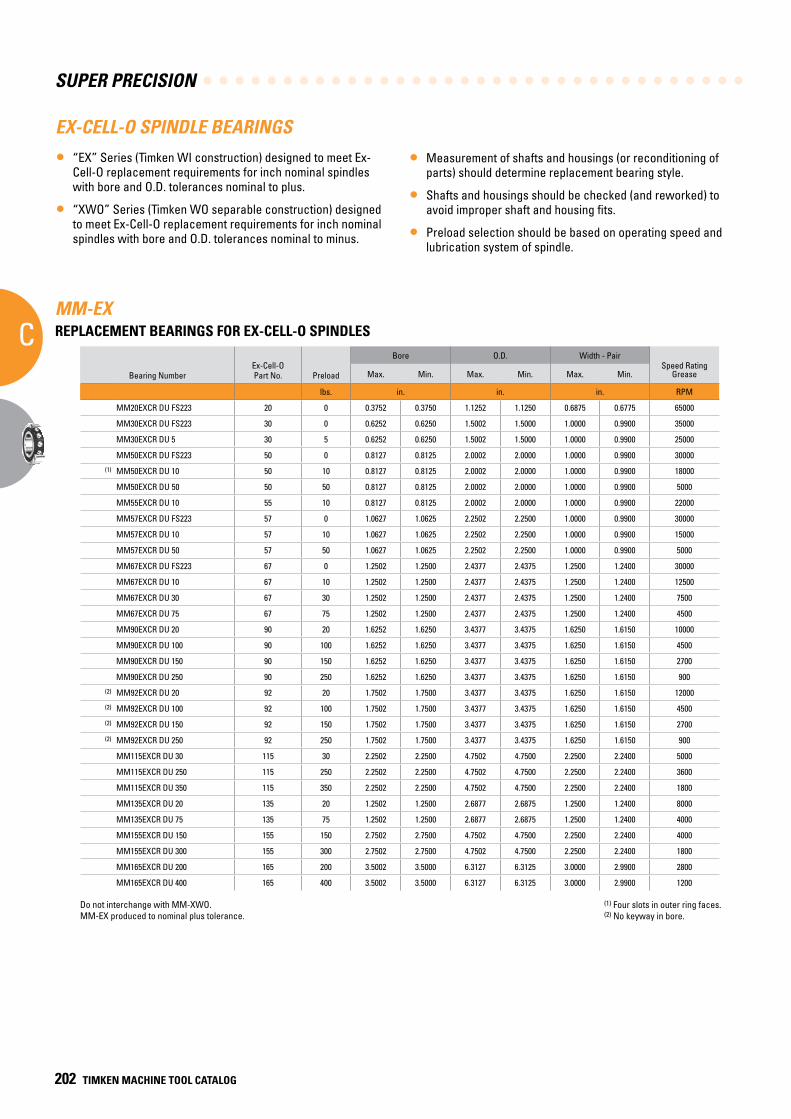
SUPER PRECISION
C
202 TIMKEN MACHINE TOOL CATALOG
EX-CELL-O SPINDLE BEARINGS
• “EX” Series (Timken WI construction) designed to meet Ex-Cell-O replacement requirements for inch nominal spindles with bore and O.D. tolerances nominal to plus.
• “XWO” Series (Timken WO separable construction) designed to meet Ex-Cell-O replacement requirements for inch nominal spindles with bore and O.D. tolerances nominal to minus.
• Measurement of shafts and housings (or reconditioning of parts) should determine replacement bearing style.
• Shafts and housings should be checked (and reworked) to avoid improper shaft and housing fits.
• Preload selection should be based on operating speed and lubrication system of spindle.
MM-EX REPLACEMENT BEARINGS FOR EX-CELL-O SPINDLES
Bearing NumberEx-Cell-O Part No. Preload
Bore O.D. Width - PairSpeed Rating
GreaseMax. Min. Max. Min. Max. Min.
lbs. in. in. in. RPM
MM20EXCR DU FS223 20 0 0.3752 0.3750 1.1252 1.1250 0.6875 0.6775 65000
MM30EXCR DU FS223 30 0 0.6252 0.6250 1.5002 1.5000 1.0000 0.9900 35000
MM30EXCR DU 5 30 5 0.6252 0.6250 1.5002 1.5000 1.0000 0.9900 25000
MM50EXCR DU FS223 50 0 0.8127 0.8125 2.0002 2.0000 1.0000 0.9900 30000
(1) MM50EXCR DU 10 50 10 0.8127 0.8125 2.0002 2.0000 1.0000 0.9900 18000
MM50EXCR DU 50 50 50 0.8127 0.8125 2.0002 2.0000 1.0000 0.9900 5000
MM55EXCR DU 10 55 10 0.8127 0.8125 2.0002 2.0000 1.0000 0.9900 22000
MM57EXCR DU FS223 57 0 1.0627 1.0625 2.2502 2.2500 1.0000 0.9900 30000
MM57EXCR DU 10 57 10 1.0627 1.0625 2.2502 2.2500 1.0000 0.9900 15000
MM57EXCR DU 50 57 50 1.0627 1.0625 2.2502 2.2500 1.0000 0.9900 5000
MM67EXCR DU FS223 67 0 1.2502 1.2500 2.4377 2.4375 1.2500 1.2400 30000
MM67EXCR DU 10 67 10 1.2502 1.2500 2.4377 2.4375 1.2500 1.2400 12500
MM67EXCR DU 30 67 30 1.2502 1.2500 2.4377 2.4375 1.2500 1.2400 7500
MM67EXCR DU 75 67 75 1.2502 1.2500 2.4377 2.4375 1.2500 1.2400 4500
MM90EXCR DU 20 90 20 1.6252 1.6250 3.4377 3.4375 1.6250 1.6150 10000
MM90EXCR DU 100 90 100 1.6252 1.6250 3.4377 3.4375 1.6250 1.6150 4500
MM90EXCR DU 150 90 150 1.6252 1.6250 3.4377 3.4375 1.6250 1.6150 2700
MM90EXCR DU 250 90 250 1.6252 1.6250 3.4377 3.4375 1.6250 1.6150 900
(2) MM92EXCR DU 20 92 20 1.7502 1.7500 3.4377 3.4375 1.6250 1.6150 12000
(2) MM92EXCR DU 100 92 100 1.7502 1.7500 3.4377 3.4375 1.6250 1.6150 4500
(2) MM92EXCR DU 150 92 150 1.7502 1.7500 3.4377 3.4375 1.6250 1.6150 2700
(2) MM92EXCR DU 250 92 250 1.7502 1.7500 3.4377 3.4375 1.6250 1.6150 900
MM115EXCR DU 30 115 30 2.2502 2.2500 4.7502 4.7500 2.2500 2.2400 5000
MM115EXCR DU 250 115 250 2.2502 2.2500 4.7502 4.7500 2.2500 2.2400 3600
MM115EXCR DU 350 115 350 2.2502 2.2500 4.7502 4.7500 2.2500 2.2400 1800
MM135EXCR DU 20 135 20 1.2502 1.2500 2.6877 2.6875 1.2500 1.2400 8000
MM135EXCR DU 75 135 75 1.2502 1.2500 2.6877 2.6875 1.2500 1.2400 4000
MM155EXCR DU 150 155 150 2.7502 2.7500 4.7502 4.7500 2.2500 2.2400 4000
MM155EXCR DU 300 155 300 2.7502 2.7500 4.7502 4.7500 2.2500 2.2400 1800
MM165EXCR DU 200 165 200 3.5002 3.5000 6.3127 6.3125 3.0000 2.9900 2800
MM165EXCR DU 400 165 400 3.5002 3.5000 6.3127 6.3125 3.0000 2.9900 1200
Do not interchange with MM-XWO.MM-EX produced to nominal plus tolerance.
(1) Four slots in outer ring faces. (2) No keyway in bore.
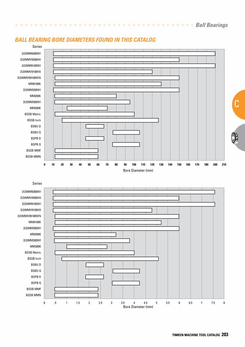
Ball Bearings
C
TIMKEN MACHINE TOOL CATALOG 203
(1) Four slots in outer ring faces. (2) No keyway in bore.
BALL BEARING BORE DIAMETERS FOUND IN THIS CATALOG
2(3)MM9300WI
2(3)MMV9300HX
2(3)MM9100WI
2(3)MMV9100HX
2(3)MMV99100WN
MM9100K
2(3)MM200WI
MM200K
2(3)MM300WI
MM300K
BSSB Metric
BSSB Inch
BSBU D
BSBU Q
BSPB D
BSPB Q
BSSB MMF
BSSB MMN
0 10 20 30 40 50 60 70 80 90 100 110 120 130 140 150 160 170 180 200 210
Ball Bearing Bore Diameters Found In This Catalog
Bore Diameter (mm)
Series
2(3)MM9300WI
2(3)MMV9300HX
2(3)MM9100WI
2(3)MMV9100HX
2(3)MMV99100WN
MM9100K
2(3)MM200WI
MM200K
2(3)MM300WI
MM300K
BSSB Metric
BSSB Inch
BSBU D
BSBU Q
BSPB D
BSPB Q
BSSB MMF
BSSB MMN
0 .5 1 1.5 2 2.5 3 3.5 4 4.5 5 5.5 6 6.5 7 7.5 8
Bore Diameter (in.)
Series
Bore Diameter (mm)
Series
Series
Bore Diameter (mm)
SUPER PRECISION
C
204 TIMKEN MACHINE TOOL CATALOG
NOTES
AD
Appendix
TIMKEN MACHINE TOOL CATALOG 209
DAPPENDIX
D
D APPENDIX
Frequency Coefficients . . . . . . . . . . . . . . . . . . . . . . . . . . . . . 206
Tapered Roller Bearings . . . . . . . . . . . . . . . . . . . . . . . . . 206
Ball Bearings . . . . . . . . . . . . . . . . . . . . . . . . . . . . . . . . . . 210
Ball Screw Support Series . . . . . . . . . . . . . . . . . . . . . . 222
Precision Tag Deviation and Runout Charts . . . . . . . . . . . 223
Geometry Factors . . . . . . . . . . . . . . . . . . . . . . . . . . . . . . . . . . 225
Radial Internal Clearance . . . . . . . . . . . . . . . . . . . . . . . . . . . 227
Bearing Locknuts . . . . . . . . . . . . . . . . . . . . . . . . . . . . . . . . . . 228
Locknut Torque . . . . . . . . . . . . . . . . . . . . . . . . . . . . . . . . . . . . 228
Lubrication Specifications . . . . . . . . . . . . . . . . . . . . . . . . . . 229
Operating Temperatures for Bearing
Component Materials . . . . . . . . . . . . . . . . . . . . . . . . . . . 231
Conversion Tables . . . . . . . . . . . . . . . . . . . . . . . . . . . . . . . . . 232
Forms . . . . . . . . . . . . . . . . . . . . . . . . . . . . . . . . . . . . . . . . . . . . . 233
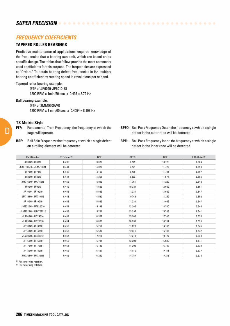
SUPER PRECISION
D
206 TIMKEN MACHINE TOOL CATALOG
FREQUENCY COEFFICIENTSTAPERED ROLLER BEARINGS
Predictive maintenance of applications requires knowledge of the frequencies that a bearing can emit, which are based on its specific design. The tables that follow provide the most commonly used coefficients for this purpose. The frequencies are expressed as "Orders." To obtain bearing defect frequencies in Hz, multiply bearing coefficient by rotating speed in revolutions per second.
Tapered roller bearing example: (FTF of JP6049-JP6010-B) 1200 RPM x 1min/60 sec x 0.436 = 8.72 Hz
Ball bearing example: (FTF of 2MM9300WI) 1200 RPM x 1 min/60 sec x 0.4054 = 8.108 Hz
Part Number FTF-Inner(1) BSF BPFO BPFI FTF-Outer(2)
JP6049-JP6010 0.436 3.676 8.275 10.725 0.564
JLM710949C-JLM710910 0.441 4.070 9.271 11.729 0.559
JP7049-JP7010 0.443 4.160 9.299 11.701 0.557
JP8049-JP8010 0.444 4.255 9.323 11.677 0.556
JM716649-JM716610 0.452 5.019 11.761 14.239 0.548
JP9049-JP9010 0.449 4.669 10.331 12.669 0.551
JP10044-JP10010 0.453 5.093 11.331 13.669 0.547
JM719149-JM719113 0.448 4.580 10.748 13.252 0.552
JP10049-JP10010 0.453 5.093 11.331 13.669 0.547
JM822049-JM822010 0.454 5.169 12.260 14.740 0.546
JLM722948-JLM722912 0.459 5.761 13.297 15.703 0.541
JL724348-JL724314 0.462 6.367 15.260 17.740 0.538
JL725346-JL725316 0.464 6.606 16.236 18.764 0.536
JP13049-JP13010 0.455 5.252 11.820 14.180 0.545
JP14049-JP14010 0.458 5.587 12.811 15.189 0.542
JL730646-JL730612 0.467 7.219 17.273 19.727 0.533
JP16049-JP16010 0.459 5.791 13.308 15.692 0.541
JP17049-JP17010 0.461 6.132 14.292 16.708 0.539
JP18049-JP18010 0.463 6.437 14.816 17.184 0.537
JM736149-JM736110 0.462 6.290 14.787 17.213 0.538
FTF: Fundamental Train Frequency: the frequency at which the cage will operate.
BSF: Ball Spin Frequency: the frequency at which a single defect on a rolling element will be detected.
BPFO: Ball Pass Frequency Outer: the frequency at which a single defect in the outer race will be detected.
BPFI: Ball Pass Frequency Inner: the frequency at which a single defect in the inner race will be detected.
TS Metric Style
(1) For inner ring rotation. (2) For outer ring rotation.
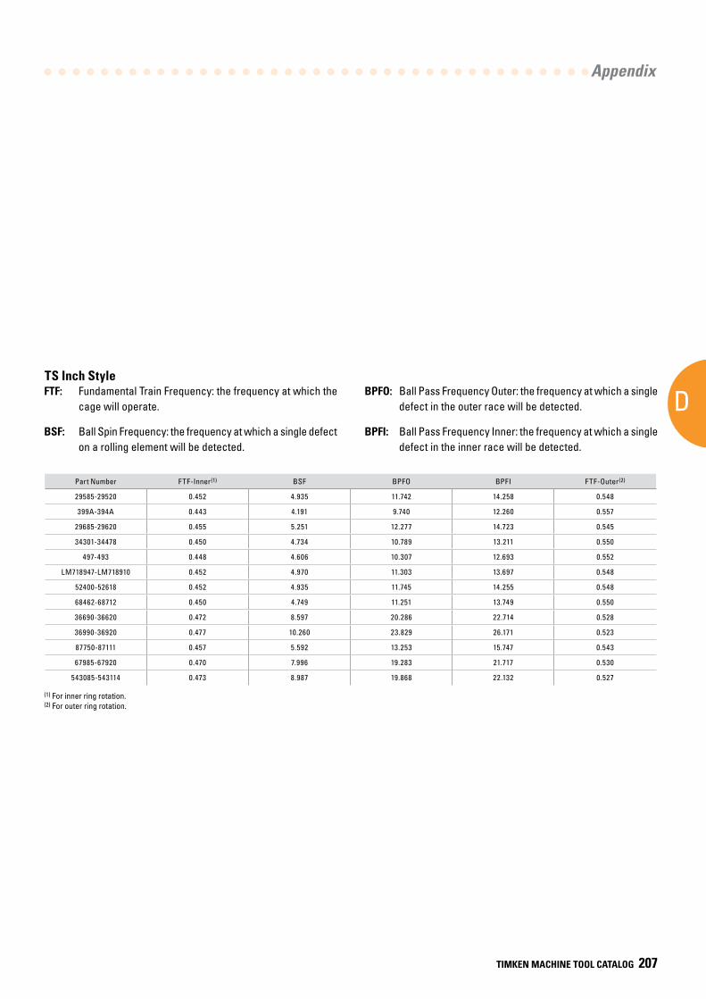
AD
Appendix
TIMKEN MACHINE TOOL CATALOG 207
Part Number FTF-Inner(1) BSF BPFO BPFI FTF-Outer(2)
29585-29520 0.452 4.935 11.742 14.258 0.548
399A-394A 0.443 4.191 9.740 12.260 0.557
29685-29620 0.455 5.251 12.277 14.723 0.545
34301-34478 0.450 4.734 10.789 13.211 0.550
497-493 0.448 4.606 10.307 12.693 0.552
LM718947-LM718910 0.452 4.970 11.303 13.697 0.548
52400-52618 0.452 4.935 11.745 14.255 0.548
68462-68712 0.450 4.749 11.251 13.749 0.550
36690-36620 0.472 8.597 20.286 22.714 0.528
36990-36920 0.477 10.260 23.829 26.171 0.523
87750-87111 0.457 5.592 13.253 15.747 0.543
67985-67920 0.470 7.996 19.283 21.717 0.530
543085-543114 0.473 8.987 19.868 22.132 0.527
TS Inch Style
(1) For inner ring rotation.(2) For outer ring rotation.
FTF: Fundamental Train Frequency: the frequency at which the cage will operate.
BSF: Ball Spin Frequency: the frequency at which a single defect on a rolling element will be detected.
BPFO: Ball Pass Frequency Outer: the frequency at which a single defect in the outer race will be detected.
BPFI: Ball Pass Frequency Inner: the frequency at which a single defect in the inner race will be detected.
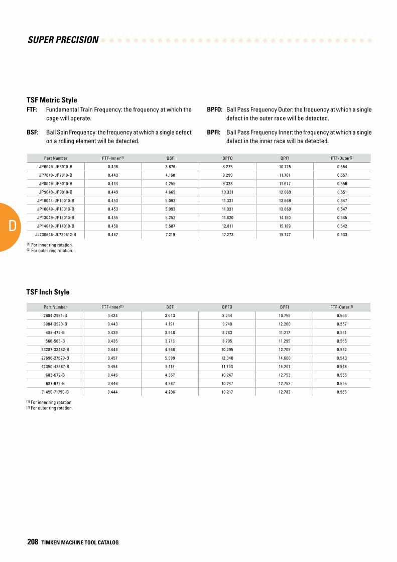
SUPER PRECISION
D
208 TIMKEN MACHINE TOOL CATALOG
Part Number FTF-Inner(1) BSF BPFO BPFI FTF-Outer(2)
JP6049-JP6010-B 0.436 3.676 8.275 10.725 0.564
JP7049-JP7010-B 0.443 4.160 9.299 11.701 0.557
JP8049-JP8010-B 0.444 4.255 9.323 11.677 0.556
JP9049-JP9010-B 0.449 4.669 10.331 12.669 0.551
JP10044-JP10010-B 0.453 5.093 11.331 13.669 0.547
JP10049-JP10010-B 0.453 5.093 11.331 13.669 0.547
JP13049-JP13010-B 0.455 5.252 11.820 14.180 0.545
JP14049-JP14010-B 0.458 5.587 12.811 15.189 0.542
JL730646-JL730612-B 0.467 7.219 17.273 19.727 0.533
FTF: Fundamental Train Frequency: the frequency at which the cage will operate.
BSF: Ball Spin Frequency: the frequency at which a single defect on a rolling element will be detected.
BPFO: Ball Pass Frequency Outer: the frequency at which a single defect in the outer race will be detected.
BPFI: Ball Pass Frequency Inner: the frequency at which a single defect in the inner race will be detected.
(1) For inner ring rotation.(2) For outer ring rotation.
TSF Metric Style
Part Number FTF-Inner(1) BSF BPFO BPFI FTF-Outer(2)
2984-2924-B 0.434 3.643 8.244 10.755 0.566
3984-3920-B 0.443 4.191 9.740 12.260 0.557
482-472-B 0.439 3.948 8.783 11.217 0.561
566-563-B 0.435 3.713 8.705 11.295 0.565
33287-33462-B 0.448 4.568 10.295 12.705 0.552
27690-27620-B 0.457 5.599 12.340 14.660 0.543
42350-42587-B 0.454 5.118 11.793 14.207 0.546
683-672-B 0.446 4.367 10.247 12.753 0.555
687-672-B 0.446 4.367 10.247 12.753 0.555
71450-71750-B 0.444 4.296 10.217 12.783 0.556
(1) For inner ring rotation.(2) For outer ring rotation.
TSF Inch Style
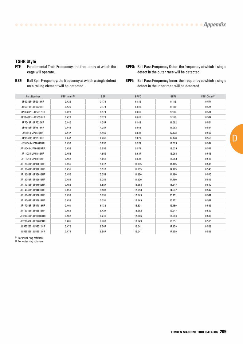
AD
Appendix
TIMKEN MACHINE TOOL CATALOG 209
Part Number FTF-Inner(1) BSF BPFO BPFI FTF-Outer(2)
JP5049P-JP5019HR 0.426 3.178 6.815 9.185 0.574
JP5049P-JP5020HR 0.426 3.178 6.815 9.185 0.574
JP5049PH-JP5017HR 0.426 3.178 6.815 9.185 0.574
JP5049PH-JP5020HR 0.426 3.178 6.815 9.185 0.574
JP7548P-JP7520HR 0.446 4.387 8.918 11.082 0.554
JP7549P-JP7519HR 0.446 4.387 8.918 11.082 0.554
JP8548-JP8518HR 0.447 4.462 9.827 12.173 0.553
JP8549P-JP8519HR 0.447 4.462 9.827 12.173 0.553
JP10048-JP10019HR 0.453 5.093 9.971 12.029 0.547
JP10048-JP10019HRA 0.453 5.093 9.971 12.029 0.547
JP11035-JP11019HR 0.452 4.955 9.937 12.063 0.548
JP11048-JP11019HR 0.452 4.955 9.937 12.063 0.548
JP12043P-JP12019HR 0.455 5.317 11.835 14.165 0.545
JP12049P-JP12019HR 0.455 5.317 11.835 14.165 0.545
JP13043P-JP13016HR 0.455 5.252 11.820 14.180 0.545
JP13049P-JP13016HR 0.455 5.252 11.820 14.180 0.545
JP14043P-JP14019HR 0.458 5.587 12.353 14.647 0.542
JP14049P-JP14019HR 0.458 5.587 12.353 14.647 0.542
JP16043P-JP16019HR 0.459 5.791 12.849 15.151 0.541
JP16049P-JP16019HR 0.459 5.791 12.849 15.151 0.541
JP17049P-JP17019HR 0.461 6.132 13.831 16.169 0.539
JP18049P-JP18019HR 0.463 6.437 14.353 16.647 0.537
JP20049P-JP20019HR 0.462 6.240 12.006 13.994 0.538
JP22049E-JP22019HR 0.465 6.769 13.949 16.051 0.535
JL555235-JL55512HR 0.472 8.567 16.041 17.959 0.528
JL555239-JL55512HR 0.472 8.567 16.041 17.959 0.528
TSHR Style
(1) For inner ring rotation.(2) For outer ring rotation.
FTF: Fundamental Train Frequency: the frequency at which the cage will operate.
BSF: Ball Spin Frequency: the frequency at which a single defect on a rolling element will be detected.
BPFO: Ball Pass Frequency Outer: the frequency at which a single defect in the outer race will be detected.
BPFI: Ball Pass Frequency Inner: the frequency at which a single defect in the inner race will be detected.
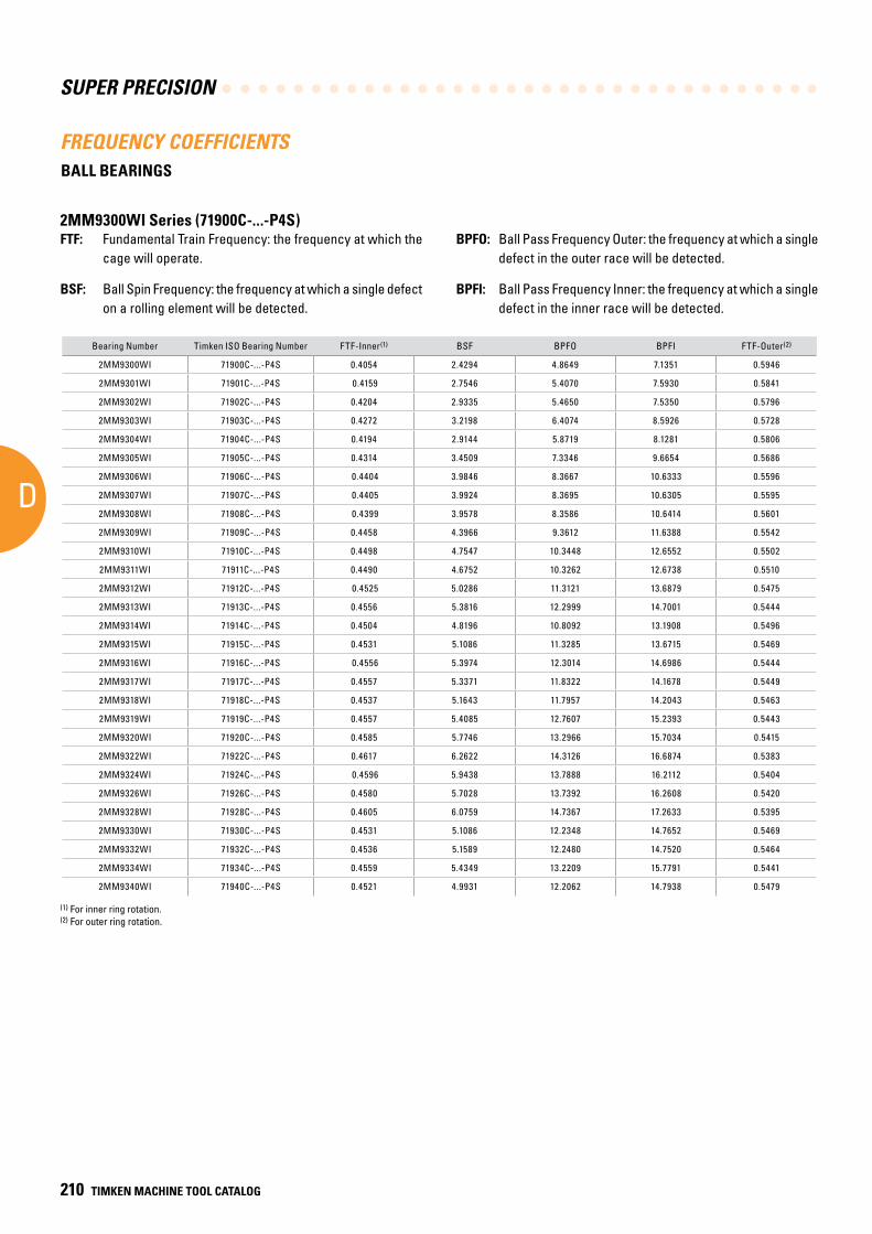
SUPER PRECISION
D
210 TIMKEN MACHINE TOOL CATALOG
FREQUENCY COEFFICIENTS
Bearing Number Timken ISO Bearing Number FTF-Inner(1) BSF BPFO BPFI FTF-Outer(2)
2MM9300WI 71900C-...-P4S 0.4054 2.4294 4.8649 7.1351 0.5946
2MM9301WI 71901C-...-P4S 0.4159 2.7546 5.4070 7.5930 0.5841
2MM9302WI 71902C-...-P4S 0.4204 2.9335 5.4650 7.5350 0.5796
2MM9303WI 71903C-...-P4S 0.4272 3.2198 6.4074 8.5926 0.5728
2MM9304WI 71904C-...-P4S 0.4194 2.9144 5.8719 8.1281 0.5806
2MM9305WI 71905C-...-P4S 0.4314 3.4509 7.3346 9.6654 0.5686
2MM9306WI 71906C-...-P4S 0.4404 3.9846 8.3667 10.6333 0.5596
2MM9307WI 71907C-...-P4S 0.4405 3.9924 8.3695 10.6305 0.5595
2MM9308WI 71908C-...-P4S 0.4399 3.9578 8.3586 10.6414 0.5601
2MM9309WI 71909C-...-P4S 0.4458 4.3966 9.3612 11.6388 0.5542
2MM9310WI 71910C-...-P4S 0.4498 4.7547 10.3448 12.6552 0.5502
2MM9311WI 71911C-...-P4S 0.4490 4.6752 10.3262 12.6738 0.5510
2MM9312WI 71912C-...-P4S 0.4525 5.0286 11.3121 13.6879 0.5475
2MM9313WI 71913C-...-P4S 0.4556 5.3816 12.2999 14.7001 0.5444
2MM9314WI 71914C-...-P4S 0.4504 4.8196 10.8092 13.1908 0.5496
2MM9315WI 71915C-...-P4S 0.4531 5.1086 11.3285 13.6715 0.5469
2MM9316WI 71916C-...-P4S 0.4556 5.3974 12.3014 14.6986 0.5444
2MM9317WI 71917C-...-P4S 0.4557 5.3371 11.8322 14.1678 0.5449
2MM9318WI 71918C-...-P4S 0.4537 5.1643 11.7957 14.2043 0.5463
2MM9319WI 71919C-...-P4S 0.4557 5.4085 12.7607 15.2393 0.5443
2MM9320WI 71920C-...-P4S 0.4585 5.7746 13.2966 15.7034 0.5415
2MM9322WI 71922C-...-P4S 0.4617 6.2622 14.3126 16.6874 0.5383
2MM9324WI 71924C-...-P4S 0.4596 5.9438 13.7888 16.2112 0.5404
2MM9326WI 71926C-...-P4S 0.4580 5.7028 13.7392 16.2608 0.5420
2MM9328WI 71928C-...-P4S 0.4605 6.0759 14.7367 17.2633 0.5395
2MM9330WI 71930C-...-P4S 0.4531 5.1086 12.2348 14.7652 0.5469
2MM9332WI 71932C-...-P4S 0.4536 5.1589 12.2480 14.7520 0.5464
2MM9334WI 71934C-...-P4S 0.4559 5.4349 13.2209 15.7791 0.5441
2MM9340WI 71940C-...-P4S 0.4521 4.9931 12.2062 14.7938 0.5479
FTF: Fundamental Train Frequency: the frequency at which the cage will operate.
BSF: Ball Spin Frequency: the frequency at which a single defect on a rolling element will be detected.
(1) For inner ring rotation.(2) For outer ring rotation.
BPFO: Ball Pass Frequency Outer: the frequency at which a single defect in the outer race will be detected.
BPFI: Ball Pass Frequency Inner: the frequency at which a single defect in the inner race will be detected.
2MM9300WI Series (71900C-...-P4S)
BALL BEARINGS
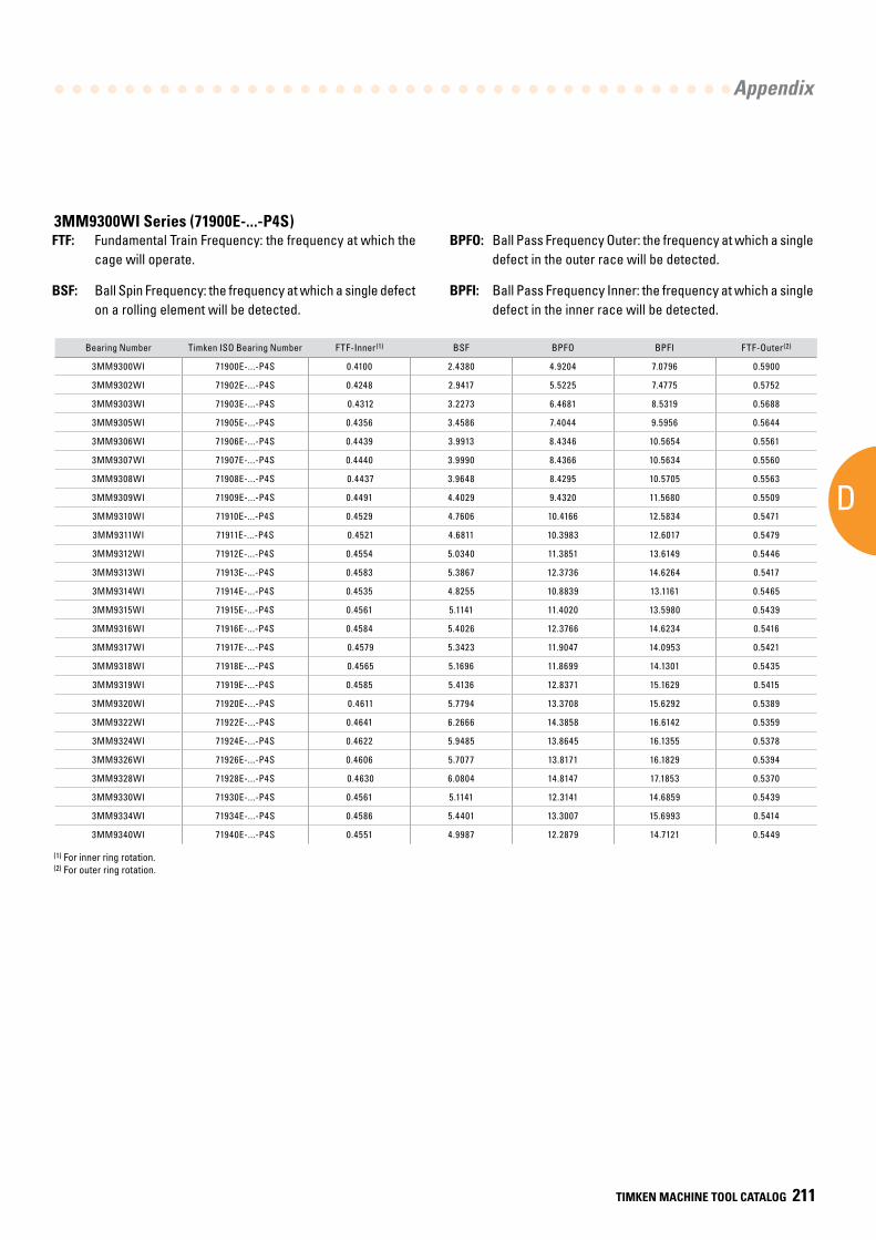
AD
Appendix
TIMKEN MACHINE TOOL CATALOG 211
Bearing Number Timken ISO Bearing Number FTF-Inner(1) BSF BPFO BPFI FTF-Outer(2)
3MM9300WI 71900E-...-P4S 0.4100 2.4380 4.9204 7.0796 0.5900
3MM9302WI 71902E-...-P4S 0.4248 2.9417 5.5225 7.4775 0.5752
3MM9303WI 71903E-...-P4S 0.4312 3.2273 6.4681 8.5319 0.5688
3MM9305WI 71905E-...-P4S 0.4356 3.4586 7.4044 9.5956 0.5644
3MM9306WI 71906E-...-P4S 0.4439 3.9913 8.4346 10.5654 0.5561
3MM9307WI 71907E-...-P4S 0.4440 3.9990 8.4366 10.5634 0.5560
3MM9308WI 71908E-...-P4S 0.4437 3.9648 8.4295 10.5705 0.5563
3MM9309WI 71909E-...-P4S 0.4491 4.4029 9.4320 11.5680 0.5509
3MM9310WI 71910E-...-P4S 0.4529 4.7606 10.4166 12.5834 0.5471
3MM9311WI 71911E-...-P4S 0.4521 4.6811 10.3983 12.6017 0.5479
3MM9312WI 71912E-...-P4S 0.4554 5.0340 11.3851 13.6149 0.5446
3MM9313WI 71913E-...-P4S 0.4583 5.3867 12.3736 14.6264 0.5417
3MM9314WI 71914E-...-P4S 0.4535 4.8255 10.8839 13.1161 0.5465
3MM9315WI 71915E-...-P4S 0.4561 5.1141 11.4020 13.5980 0.5439
3MM9316WI 71916E-...-P4S 0.4584 5.4026 12.3766 14.6234 0.5416
3MM9317WI 71917E-...-P4S 0.4579 5.3423 11.9047 14.0953 0.5421
3MM9318WI 71918E-...-P4S 0.4565 5.1696 11.8699 14.1301 0.5435
3MM9319WI 71919E-...-P4S 0.4585 5.4136 12.8371 15.1629 0.5415
3MM9320WI 71920E-...-P4S 0.4611 5.7794 13.3708 15.6292 0.5389
3MM9322WI 71922E-...-P4S 0.4641 6.2666 14.3858 16.6142 0.5359
3MM9324WI 71924E-...-P4S 0.4622 5.9485 13.8645 16.1355 0.5378
3MM9326WI 71926E-...-P4S 0.4606 5.7077 13.8171 16.1829 0.5394
3MM9328WI 71928E-...-P4S 0.4630 6.0804 14.8147 17.1853 0.5370
3MM9330WI 71930E-...-P4S 0.4561 5.1141 12.3141 14.6859 0.5439
3MM9334WI 71934E-...-P4S 0.4586 5.4401 13.3007 15.6993 0.5414
3MM9340WI 71940E-...-P4S 0.4551 4.9987 12.2879 14.7121 0.5449
FTF: Fundamental Train Frequency: the frequency at which the cage will operate.
BSF: Ball Spin Frequency: the frequency at which a single defect on a rolling element will be detected.
BPFO: Ball Pass Frequency Outer: the frequency at which a single defect in the outer race will be detected.
BPFI: Ball Pass Frequency Inner: the frequency at which a single defect in the inner race will be detected.
(1) For inner ring rotation. (2) For outer ring rotation.
3MM9300WI Series (71900E-...-P4S)
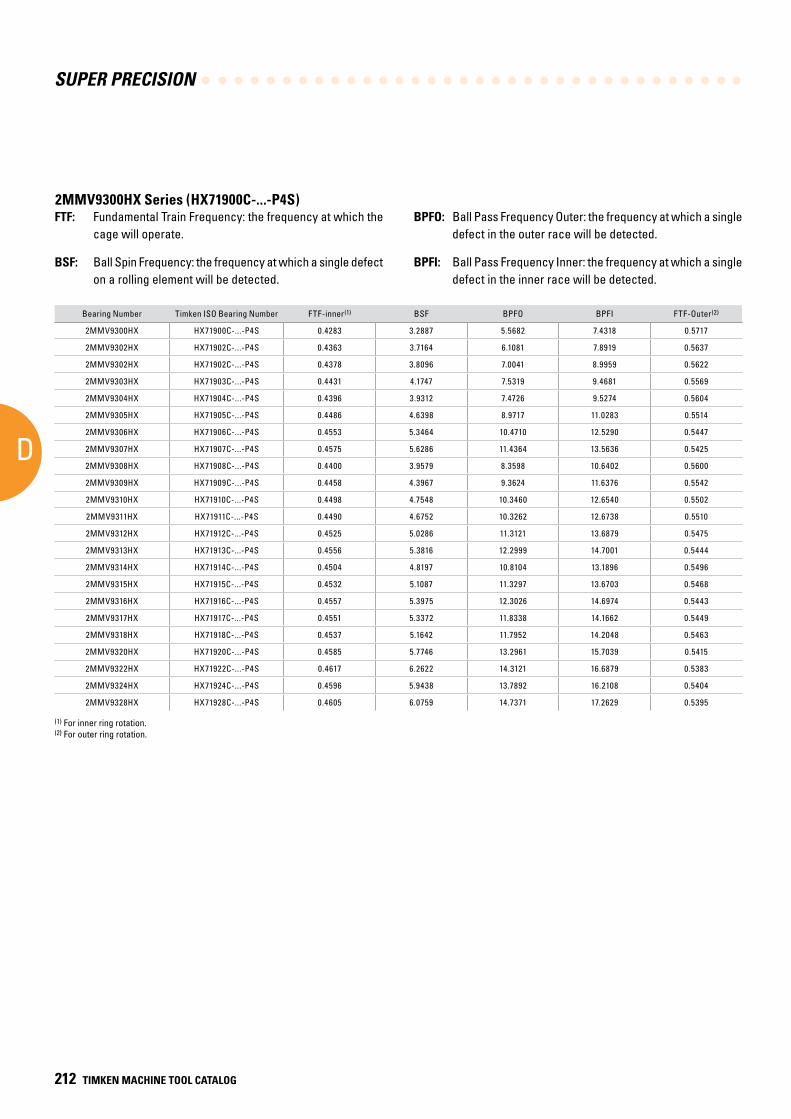
SUPER PRECISION
D
212 TIMKEN MACHINE TOOL CATALOG
Bearing Number Timken ISO Bearing Number FTF-inner(1) BSF BPFO BPFI FTF-Outer(2)
2MMV9300HX HX71900C-...-P4S 0.4283 3.2887 5.5682 7.4318 0.5717
2MMV9302HX HX71902C-...-P4S 0.4363 3.7164 6.1081 7.8919 0.5637
2MMV9302HX HX71902C-...-P4S 0.4378 3.8096 7.0041 8.9959 0.5622
2MMV9303HX HX71903C-...-P4S 0.4431 4.1747 7.5319 9.4681 0.5569
2MMV9304HX HX71904C-...-P4S 0.4396 3.9312 7.4726 9.5274 0.5604
2MMV9305HX HX71905C-...-P4S 0.4486 4.6398 8.9717 11.0283 0.5514
2MMV9306HX HX71906C-...-P4S 0.4553 5.3464 10.4710 12.5290 0.5447
2MMV9307HX HX71907C-...-P4S 0.4575 5.6286 11.4364 13.5636 0.5425
2MMV9308HX HX71908C-...-P4S 0.4400 3.9579 8.3598 10.6402 0.5600
2MMV9309HX HX71909C-...-P4S 0.4458 4.3967 9.3624 11.6376 0.5542
2MMV9310HX HX71910C-...-P4S 0.4498 4.7548 10.3460 12.6540 0.5502
2MMV9311HX HX71911C-...-P4S 0.4490 4.6752 10.3262 12.6738 0.5510
2MMV9312HX HX71912C-...-P4S 0.4525 5.0286 11.3121 13.6879 0.5475
2MMV9313HX HX71913C-...-P4S 0.4556 5.3816 12.2999 14.7001 0.5444
2MMV9314HX HX71914C-...-P4S 0.4504 4.8197 10.8104 13.1896 0.5496
2MMV9315HX HX71915C-...-P4S 0.4532 5.1087 11.3297 13.6703 0.5468
2MMV9316HX HX71916C-...-P4S 0.4557 5.3975 12.3026 14.6974 0.5443
2MMV9317HX HX71917C-...-P4S 0.4551 5.3372 11.8338 14.1662 0.5449
2MMV9318HX HX71918C-...-P4S 0.4537 5.1642 11.7952 14.2048 0.5463
2MMV9320HX HX71920C-...-P4S 0.4585 5.7746 13.2961 15.7039 0.5415
2MMV9322HX HX71922C-...-P4S 0.4617 6.2622 14.3121 16.6879 0.5383
2MMV9324HX HX71924C-...-P4S 0.4596 5.9438 13.7892 16.2108 0.5404
2MMV9328HX HX71928C-...-P4S 0.4605 6.0759 14.7371 17.2629 0.5395
(1) For inner ring rotation.(2) For outer ring rotation.
2MMV9300HX Series (HX71900C-...-P4S)FTF: Fundamental Train Frequency: the frequency at which the
cage will operate.
BSF: Ball Spin Frequency: the frequency at which a single defect on a rolling element will be detected.
BPFO: Ball Pass Frequency Outer: the frequency at which a single defect in the outer race will be detected.
BPFI: Ball Pass Frequency Inner: the frequency at which a single defect in the inner race will be detected.
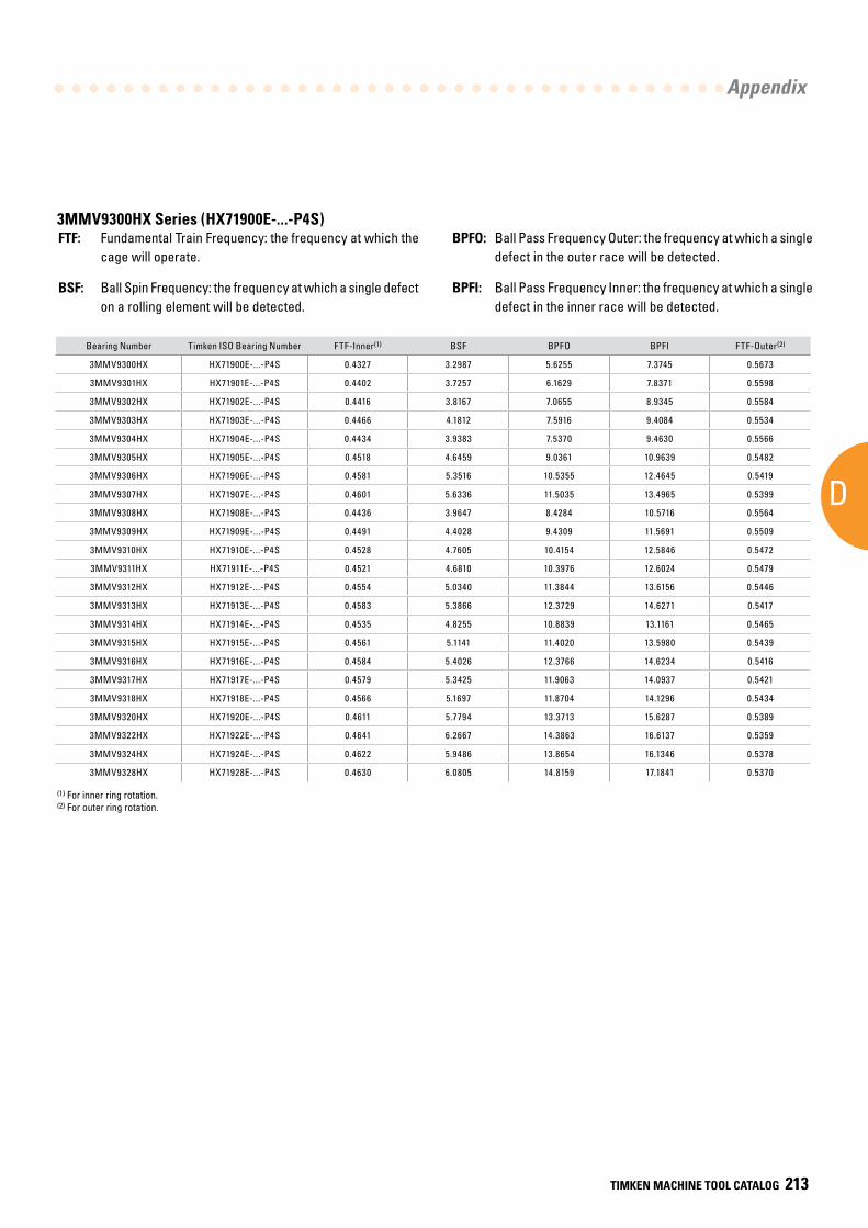
AD
Appendix
TIMKEN MACHINE TOOL CATALOG 213
Bearing Number Timken ISO Bearing Number FTF-Inner(1) BSF BPFO BPFI FTF-Outer(2)
3MMV9300HX HX71900E-...-P4S 0.4327 3.2987 5.6255 7.3745 0.5673
3MMV9301HX HX71901E-...-P4S 0.4402 3.7257 6.1629 7.8371 0.5598
3MMV9302HX HX71902E-...-P4S 0.4416 3.8167 7.0655 8.9345 0.5584
3MMV9303HX HX71903E-...-P4S 0.4466 4.1812 7.5916 9.4084 0.5534
3MMV9304HX HX71904E-...-P4S 0.4434 3.9383 7.5370 9.4630 0.5566
3MMV9305HX HX71905E-...-P4S 0.4518 4.6459 9.0361 10.9639 0.5482
3MMV9306HX HX71906E-...-P4S 0.4581 5.3516 10.5355 12.4645 0.5419
3MMV9307HX HX71907E-...-P4S 0.4601 5.6336 11.5035 13.4965 0.5399
3MMV9308HX HX71908E-...-P4S 0.4436 3.9647 8.4284 10.5716 0.5564
3MMV9309HX HX71909E-...-P4S 0.4491 4.4028 9.4309 11.5691 0.5509
3MMV9310HX HX71910E-...-P4S 0.4528 4.7605 10.4154 12.5846 0.5472
3MMV9311HX HX71911E-...-P4S 0.4521 4.6810 10.3976 12.6024 0.5479
3MMV9312HX HX71912E-...-P4S 0.4554 5.0340 11.3844 13.6156 0.5446
3MMV9313HX HX71913E-...-P4S 0.4583 5.3866 12.3729 14.6271 0.5417
3MMV9314HX HX71914E-...-P4S 0.4535 4.8255 10.8839 13.1161 0.5465
3MMV9315HX HX71915E-...-P4S 0.4561 5.1141 11.4020 13.5980 0.5439
3MMV9316HX HX71916E-...-P4S 0.4584 5.4026 12.3766 14.6234 0.5416
3MMV9317HX HX71917E-...-P4S 0.4579 5.3425 11.9063 14.0937 0.5421
3MMV9318HX HX71918E-...-P4S 0.4566 5.1697 11.8704 14.1296 0.5434
3MMV9320HX HX71920E-...-P4S 0.4611 5.7794 13.3713 15.6287 0.5389
3MMV9322HX HX71922E-...-P4S 0.4641 6.2667 14.3863 16.6137 0.5359
3MMV9324HX HX71924E-...-P4S 0.4622 5.9486 13.8654 16.1346 0.5378
3MMV9328HX HX71928E-...-P4S 0.4630 6.0805 14.8159 17.1841 0.5370
(1) For inner ring rotation.(2) For outer ring rotation.
3MMV9300HX Series (HX71900E-...-P4S)FTF: Fundamental Train Frequency: the frequency at which the
cage will operate.
BSF: Ball Spin Frequency: the frequency at which a single defect on a rolling element will be detected.
BPFO: Ball Pass Frequency Outer: the frequency at which a single defect in the outer race will be detected.
BPFI: Ball Pass Frequency Inner: the frequency at which a single defect in the inner race will be detected.
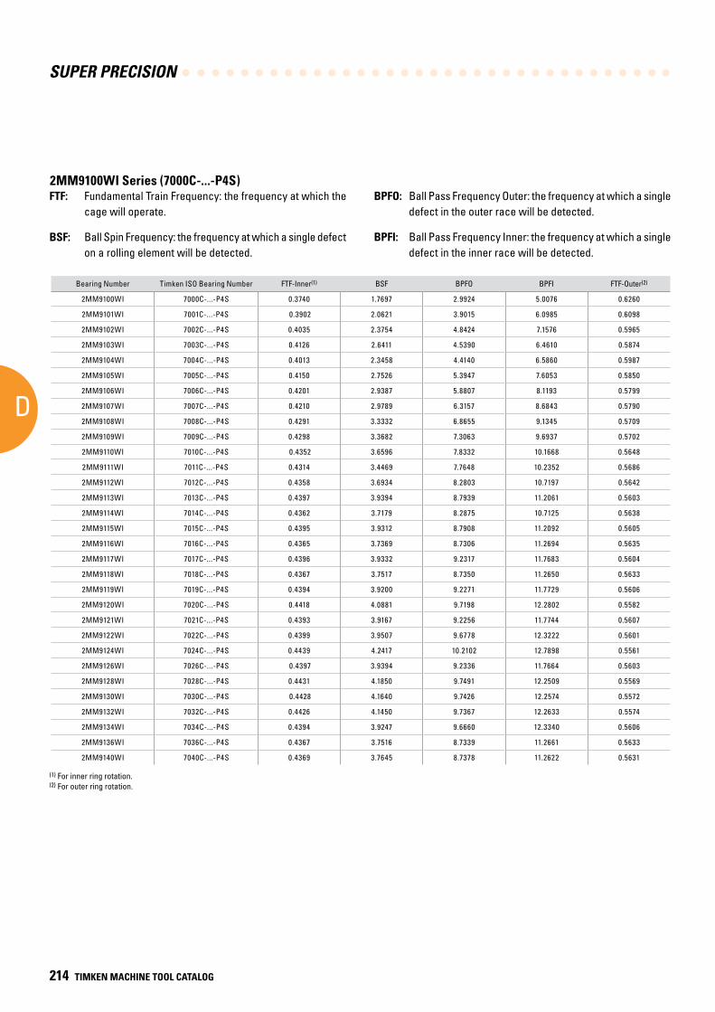
SUPER PRECISION
D
214 TIMKEN MACHINE TOOL CATALOG
Bearing Number Timken ISO Bearing Number FTF-Inner(1) BSF BPFO BPFI FTF-Outer(2)
2MM9100WI 7000C-...-P4S 0.3740 1.7697 2.9924 5.0076 0.6260
2MM9101WI 7001C-...-P4S 0.3902 2.0621 3.9015 6.0985 0.6098
2MM9102WI 7002C-...-P4S 0.4035 2.3754 4.8424 7.1576 0.5965
2MM9103WI 7003C-...-P4S 0.4126 2.6411 4.5390 6.4610 0.5874
2MM9104WI 7004C-...-P4S 0.4013 2.3458 4.4140 6.5860 0.5987
2MM9105WI 7005C-...-P4S 0.4150 2.7526 5.3947 7.6053 0.5850
2MM9106WI 7006C-...-P4S 0.4201 2.9387 5.8807 8.1193 0.5799
2MM9107WI 7007C-...-P4S 0.4210 2.9789 6.3157 8.6843 0.5790
2MM9108WI 7008C-...-P4S 0.4291 3.3332 6.8655 9.1345 0.5709
2MM9109WI 7009C-...-P4S 0.4298 3.3682 7.3063 9.6937 0.5702
2MM9110WI 7010C-...-P4S 0.4352 3.6596 7.8332 10.1668 0.5648
2MM9111WI 7011C-...-P4S 0.4314 3.4469 7.7648 10.2352 0.5686
2MM9112WI 7012C-...-P4S 0.4358 3.6934 8.2803 10.7197 0.5642
2MM9113WI 7013C-...-P4S 0.4397 3.9394 8.7939 11.2061 0.5603
2MM9114WI 7014C-...-P4S 0.4362 3.7179 8.2875 10.7125 0.5638
2MM9115WI 7015C-...-P4S 0.4395 3.9312 8.7908 11.2092 0.5605
2MM9116WI 7016C-...-P4S 0.4365 3.7369 8.7306 11.2694 0.5635
2MM9117WI 7017C-...-P4S 0.4396 3.9332 9.2317 11.7683 0.5604
2MM9118WI 7018C-...-P4S 0.4367 3.7517 8.7350 11.2650 0.5633
2MM9119WI 7019C-...-P4S 0.4394 3.9200 9.2271 11.7729 0.5606
2MM9120WI 7020C-...-P4S 0.4418 4.0881 9.7198 12.2802 0.5582
2MM9121WI 7021C-...-P4S 0.4393 3.9167 9.2256 11.7744 0.5607
2MM9122WI 7022C-...-P4S 0.4399 3.9507 9.6778 12.3222 0.5601
2MM9124WI 7024C-...-P4S 0.4439 4.2417 10.2102 12.7898 0.5561
2MM9126WI 7026C-...-P4S 0.4397 3.9394 9.2336 11.7664 0.5603
2MM9128WI 7028C-...-P4S 0.4431 4.1850 9.7491 12.2509 0.5569
2MM9130WI 7030C-...-P4S 0.4428 4.1640 9.7426 12.2574 0.5572
2MM9132WI 7032C-...-P4S 0.4426 4.1450 9.7367 12.2633 0.5574
2MM9134WI 7034C-...-P4S 0.4394 3.9247 9.6660 12.3340 0.5606
2MM9136WI 7036C-...-P4S 0.4367 3.7516 8.7339 11.2661 0.5633
2MM9140WI 7040C-...-P4S 0.4369 3.7645 8.7378 11.2622 0.5631
(1) For inner ring rotation.(2) For outer ring rotation.
2MM9100WI Series (7000C-...-P4S)FTF: Fundamental Train Frequency: the frequency at which the
cage will operate.
BSF: Ball Spin Frequency: the frequency at which a single defect on a rolling element will be detected.
BPFO: Ball Pass Frequency Outer: the frequency at which a single defect in the outer race will be detected.
BPFI: Ball Pass Frequency Inner: the frequency at which a single defect in the inner race will be detected.
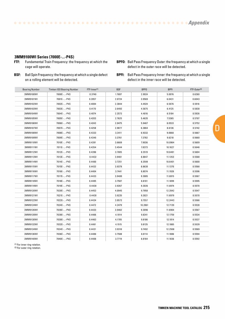
AD
Appendix
TIMKEN MACHINE TOOL CATALOG 215
Bearing Number Timken ISO Bearing Number FTF-Inner(1) BSF BPFO BPFI FTF-Outer(2)
3MM9100WI 7000E-...-P4S 0.3740 1.7697 2.9924 5.0076 0.6260
3MM9101WI 7001E-...-P4S 0.3957 2.0724 3.9569 6.0431 0.6043
3MM9102WI 7002E-...-P4S 0.4084 2.3844 4.4924 6.5076 0.5916
3MM9103WI 7003E-...-P4S 0.4170 2.6493 4.5875 6.4125 0.5830
3MM9104WI 7004E-...-P4S 0.4074 2.3573 4.4816 6.5184 0.5926
3MM9105WI 7005E-...-P4S 0.4203 2.7625 5.4635 7.5365 0.5797
3MM9106WI 7006E-...-P4S 0.4243 2.9475 5.9467 8.0533 0.5752
3MM9107WI 7007E-...-P4S 0.4258 2.9877 6.3864 8.6136 0.5742
3MM9108WI 7008E-...-P4S 0.4333 3.3411 6.9332 9.0668 0.5667
3MM9109WI 7009E-...-P4S 0.4340 3.3761 7.3782 9.6218 0.5660
3MM9110WI 7010E-...-P4S 0.4391 3.6669 7.9036 10.0964 0.5609
3MM9111WI 7011E-...-P4S 0.4354 3.4544 7.8373 10.1627 0.5646
3MM9112WI 7012E-...-P4S 0.4396 3.7005 8.3519 10.6481 0.5604
3MM9113WI 7013E-...-P4S 0.4432 3.9461 8.8647 11.1353 0.5568
3MM9114WI 7014E-...-P4S 0.4400 3.7251 8.3599 10.6401 0.5600
3MM9115WI 7015E-...-P4S 0.4432 3.9379 8.8630 11.1370 0.5568
3MM9116WI 7016E-...-P4S 0.4404 3.7441 8.8074 11.1926 0.5596
3MM9117WI 7017E-...-P4S 0.4433 3.9400 9.3085 11.6915 0.5567
3MM9118WI 7018E-...-P4S 0.4405 3.7587 8.8101 11.1899 0.5595
3MM9119WI 7019E-...-P4S 0.4430 3.9267 9.3026 11.6974 0.5570
3MM9120WI 7020E-...-P4S 0.4453 4.0945 9.7958 12.2042 0.5547
3MM9121WI 7021E-...-P4S 0.4430 3.9235 9.3021 11.6979 0.5570
3MM9122WI 7022E-...-P4S 0.4434 3.9573 9.7557 12.2443 0.5566
3MM9124WI 7024E-...-P4S 0.4472 4.2479 10.2861 12.7139 0.5528
3MM9126WI 7026E-...-P4S 0.4433 3.9462 9.3096 11.6904 0.5567
3MM9128WI 7028E-...-P4S 0.4466 4.1914 9.8241 12.1759 0.5534
3MM9130WI 7030E-...-P4S 0.4463 4.1705 9.8186 12.1814 0.5537
3MM9132WI 7032E-...-P4S 0.4461 4.1515 9.8135 12.1865 0.5539
3MM9134WI 7034E-...-P4S 0.4431 3.9318 9.7492 12.2508 0.5569
3MM9136WI 7036E-...-P4S 0.4406 3.7588 8.8114 11.1886 0.5594
3MM9140WI 7040E-...-P4S 0.4408 3.7719 8.8164 11.1836 0.5592
(1) For inner ring rotation. (2) For outer ring rotation.
3MM9100WI Series (7000E-...-P4S)FTF: Fundamental Train Frequency: the frequency at which the
cage will operate.
BSF: Ball Spin Frequency: the frequency at which a single defect on a rolling element will be detected.
BPFO: Ball Pass Frequency Outer: the frequency at which a single defect in the outer race will be detected.
BPFI: Ball Pass Frequency Inner: the frequency at which a single defect in the inner race will be detected.

SUPER PRECISION
D
216 TIMKEN MACHINE TOOL CATALOG
Bearing Number Timken ISO Bearing Number FTF-Inner(1) BSF BPFO BPFI FTF-Outer(2)
2MMV9100HX HX7000C-...-P4S 0.3834 1.9496 3.8344 6.1656 0.6166
2MMV9101HX HX7001C-...-P4S 0.3852 1.9890 3.8517 6.1483 0.6148
2MMV9102HX HX7002C-...-P4S 0.4023 2.3729 4.8273 7.1727 0.5977
2MMV9103HX HX7003C-...-P4S 0.3969 2.2403 4.7634 7.2366 0.6031
2MMV9104HX HX7004C-...-P4S 0.4012 2.3457 4.8147 7.1853 0.5988
2MMV9105HX HX7005C-...-P4S 0.4043 2.4274 5.2560 7.7440 0.5957
2MMV9106HX HX7006C-...-P4S 0.4099 2.5903 5.3292 7.6708 0.5901
2MMV9107HX HX7007C-...-P4S 0.4211 2.9789 6.3162 8.6838 0.5789
2MMV9108HX HX7008C-...-P4S 0.4291 3.3332 6.8659 9.1341 0.5709
2MMV9109HX HX7009C-...-P4S 0.4234 3.0758 6.3517 8.6483 0.5766
2MMV9110HX HX7010C-...-P4S 0.4293 3.3440 6.8694 9.1306 0.5707
2MMV9111HX HX7011C-...-P4S 0.4472 4.5160 10.7329 13.2671 0.5528
2MMV9112HX HX7012C-...-P4S 0.4506 4.8343 11.2653 13.7347 0.5494
2MMV9113HX HX7013C-...-P4S 0.4490 4.6751 11.2241 13.7759 0.5510
2MMV9114HX HX7014C-...-P4S 0.4490 4.6752 11.2241 13.7759 0.5510
2MMV9115HX HX7015C-...-P4S 0.4517 4.9403 11.7429 14.2571 0.5483
2MMV9116HX HX7016C-...-P4S 0.4477 4.5613 11.1913 13.8087 0.5523
2MMV9117HX HX7017C-...-P4S 0.4502 4.7888 11.7039 14.2961 0.5498
2MMV9118HX HX7018C-...-P4S 0.4534 5.1295 12.6953 15.3047 0.5466
2MMV9120HX HX7020C-...-P4S 0.4510 4.8740 12.1772 14.8228 0.5490
2MMV9122HX HX7022C-...-P4S 0.4563 5.4696 13.6877 16.3123 0.5437
2MMV9124HX HX7024C-...-P4S 0.4542 5.2052 13.1707 15.8293 0.5458
(1) For inner ring rotation. (2) For outer ring rotation.
2MMV9100HX Series (HX7000C-...-P4S)FTF: Fundamental Train Frequency: the frequency at which the
cage will operate.
BSF: Ball Spin Frequency: the frequency at which a single defect on a rolling element will be detected.
BPFO: Ball Pass Frequency Outer: the frequency at which a single defect in the outer race will be detected.
BPFI: Ball Pass Frequency Inner: the frequency at which a single defect in the inner race will be detected.
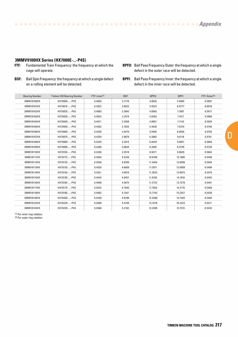
AD
Appendix
TIMKEN MACHINE TOOL CATALOG 217
Bearing Number Timken ISO Bearing Number FTF-inner(1) BSF BPFO BPFI FTF-Outer(2)
3MMV9100HX HX7000E-...-P4S 0.4003 2.1778 4.0035 5.9965 0.5997
3MMV9101HX HX7001E-...-P4S 0.3922 2.0022 3.9223 6.0777 0.6078
3MMV9102HX HX7002E-...-P4S 0.4083 2.3842 4.8993 7.1007 0.5917
3MMV9103HX HX7003E-...-P4S 0.4032 2.2519 4.8383 7.1617 0.5968
3MMV9104HX HX7004E-...-P4S 0.4071 2.3568 4.8857 7.1143 0.5929
3MMV9105HX HX7005E-...-P4S 0.4202 2.7625 5.4630 7.5370 0.5798
3MMV9106HX HX7006E-...-P4S 0.4250 2.9479 5.9495 8.0505 0.5750
3MMV9107HX HX7007E-...-P4S 0.4259 2.9879 6.3882 8.6118 0.5741
3MMV9108HX HX7008E-...-P4S 0.4334 3.3413 6.9349 9.0651 0.5666
3MMV9109HX HX7009E-...-P4S 0.4280 3.0844 6.4205 8.5795 0.5720
3MMV9110HX HX7010E-...-P4S 0.4336 3.3519 6.9371 9.0629 0.5664
3MMV9111HX HX7011E-...-P4S 0.4504 4.5220 10.8100 13.1900 0.5496
3MMV9112HX HX7012E-...-P4S 0.4536 4.8399 11.3404 13.6596 0.5464
3MMV9113HX HX7013E-...-P4S 0.4520 4.6809 11.3011 13.6989 0.5480
3MMV9114HX HX7014E-...-P4S 0.4521 4.6810 11.3025 13.6975 0.5479
3MMV9115HX HX7015E-...-P4S 0.4545 4.9457 11.8182 14.1818 0.5455
3MMV9116HX HX7016E-...-P4S 0.4509 4.5674 11.2722 13.7278 0.5491
3MMV9117HX HX7017E-...-P4S 0.4532 4.7945 11.7824 14.2176 0.5468
3MMV9118HX HX7018E-...-P4S 0.4562 5.1347 12.7743 15.2257 0.5438
3MMV9120HX HX7020E-...-P4S 0.4540 4.8796 12.2580 14.7420 0.5460
3MMV9122HX HX7022E-...-P4S 0.4589 5.4746 13.7678 16.2322 0.5411
3MMV9124HX HX7024E-...-P4S 0.4568 5.2102 13.2485 15.7515 0.5432
(1) For inner ring rotation.(2) For outer ring rotation.
3MMV9100HX Series (HX7000E-...-P4S)FTF: Fundamental Train Frequency: the frequency at which the
cage will operate.
BSF: Ball Spin Frequency: the frequency at which a single defect on a rolling element will be detected.
BPFO: Ball Pass Frequency Outer: the frequency at which a single defect in the outer race will be detected.
BPFI: Ball Pass Frequency Inner: the frequency at which a single defect in the inner race will be detected.
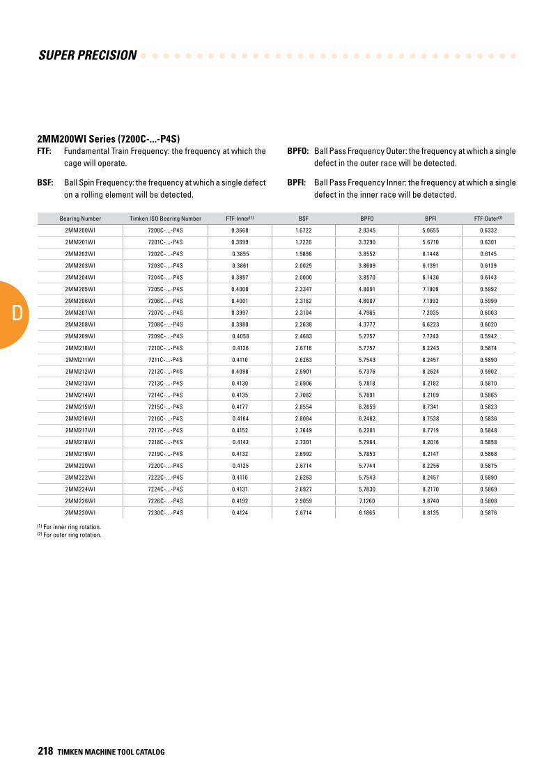
SUPER PRECISION
D
218 TIMKEN MACHINE TOOL CATALOG
Bearing Number Timken ISO Bearing Number FTF-Inner(1) BSF BPFO BPFI FTF-Outer(2)
2MM200WI 7200C-...-P4S 0.3668 1.6722 2.9345 5.0655 0.6332
2MM201WI 7201C-...-P4S 0.3699 1.7226 3.3290 5.6710 0.6301
2MM202WI 7202C-...-P4S 0.3855 1.9898 3.8552 6.1448 0.6145
2MM203WI 7203C-...-P4S 0.3861 2.0025 3.8609 6.1391 0.6139
2MM204WI 7204C-...-P4S 0.3857 2.0000 3.8570 6.1430 0.6143
2MM205WI 7205C-...-P4S 0.4008 2.3347 4.8091 7.1909 0.5992
2MM206WI 7206C-...-P4S 0.4001 2.3182 4.8007 7.1993 0.5999
2MM207WI 7207C-...-P4S 0.3997 2.3104 4.7965 7.2035 0.6003
2MM208WI 7208C-...-P4S 0.3980 2.2638 4.3777 6.6223 0.6020
2MM209WI 7209C-...-P4S 0.4058 2.4683 5.2757 7.7243 0.5942
2MM210WI 7210C-...-P4S 0.4126 2.6716 5.7757 8.2243 0.5874
2MM211WI 7211C-...-P4S 0.4110 2.6263 5.7543 8.2457 0.5890
2MM212WI 7212C-...-P4S 0.4098 2.5901 5.7376 8.2624 0.5902
2MM213WI 7213C-...-P4S 0.4130 2.6906 5.7818 8.2182 0.5870
2MM214WI 7214C-...-P4S 0.4135 2.7082 5.7891 8.2109 0.5865
2MM215WI 7215C-...-P4S 0.4177 2.8554 6.2659 8.7341 0.5823
2MM216WI 7216C-...-P4S 0.4164 2.8064 6.2462 8.7538 0.5836
2MM217WI 7217C-...-P4S 0.4152 2.7649 6.2281 8.7719 0.5848
2MM218WI 7218C-...-P4S 0.4142 2.7301 5.7984 8.2016 0.5858
2MM219WI 7219C-...-P4S 0.4132 2.6992 5.7853 8.2147 0.5868
2MM220WI 7220C-...-P4S 0.4125 2.6714 5.7744 8.2256 0.5875
2MM222WI 7222C-...-P4S 0.4110 2.6263 5.7543 8.2457 0.5890
2MM224WI 7224C-...-P4S 0.4131 2.6927 5.7830 8.2170 0.5869
2MM226WI 7226C-...-P4S 0.4192 2.9059 7.1260 9.8740 0.5808
2MM230WI 7230C-...-P4S 0.4124 2.6714 6.1865 8.8135 0.5876
(1) For inner ring rotation.(2) For outer ring rotation.
FTF: Fundamental Train Frequency: the frequency at which the cage will operate.
BSF: Ball Spin Frequency: the frequency at which a single defect on a rolling element will be detected.
BPFO: Ball Pass Frequency Outer: the frequency at which a single defect in the outer race will be detected.
BPFI: Ball Pass Frequency Inner: the frequency at which a single defect in the inner race will be detected.
2MM200WI Series (7200C-...-P4S)
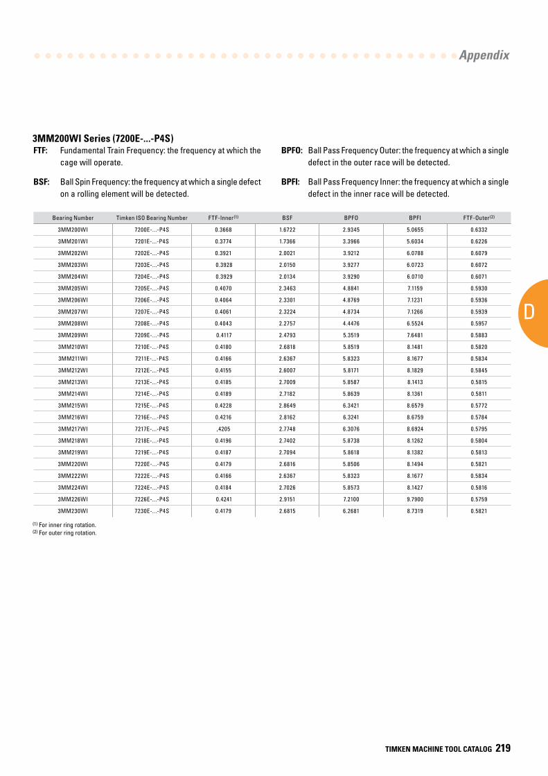
AD
Appendix
TIMKEN MACHINE TOOL CATALOG 219
Bearing Number Timken ISO Bearing Number FTF-Inner(1) BSF BPFO BPFI FTF-Outer(2)
3MM200WI 7200E-...-P4S 0.3668 1.6722 2.9345 5.0655 0.6332
3MM201WI 7201E-...-P4S 0.3774 1.7366 3.3966 5.6034 0.6226
3MM202WI 7202E-...-P4S 0.3921 2.0021 3.9212 6.0788 0.6079
3MM203WI 7203E-...-P4S 0.3928 2.0150 3.9277 6.0723 0.6072
3MM204WI 7204E-...-P4S 0.3929 2.0134 3.9290 6.0710 0.6071
3MM205WI 7205E-...-P4S 0.4070 2.3463 4.8841 7.1159 0.5930
3MM206WI 7206E-...-P4S 0.4064 2.3301 4.8769 7.1231 0.5936
3MM207WI 7207E-...-P4S 0.4061 2.3224 4.8734 7.1266 0.5939
3MM208WI 7208E-...-P4S 0.4043 2.2757 4.4476 6.5524 0.5957
3MM209WI 7209E-...-P4S 0.4117 2.4793 5.3519 7.6481 0.5883
3MM210WI 7210E-...-P4S 0.4180 2.6818 5.8519 8.1481 0.5820
3MM211WI 7211E-...-P4S 0.4166 2.6367 5.8323 8.1677 0.5834
3MM212WI 7212E-...-P4S 0.4155 2.6007 5.8171 8.1829 0.5845
3MM213WI 7213E-...-P4S 0.4185 2.7009 5.8587 8.1413 0.5815
3MM214WI 7214E-...-P4S 0.4189 2.7182 5.8639 8.1361 0.5811
3MM215WI 7215E-...-P4S 0.4228 2.8649 6.3421 8.6579 0.5772
3MM216WI 7216E-...-P4S 0.4216 2.8162 6.3241 8.6759 0.5784
3MM217WI 7217E-...-P4S ,4205 2.7748 6.3076 8.6924 0.5795
3MM218WI 7218E-...-P4S 0.4196 2.7402 5.8738 8.1262 0.5804
3MM219WI 7219E-...-P4S 0.4187 2.7094 5.8618 8.1382 0.5813
3MM220WI 7220E-...-P4S 0.4179 2.6816 5.8506 8.1494 0.5821
3MM222WI 7222E-...-P4S 0.4166 2.6367 5.8323 8.1677 0.5834
3MM224WI 7224E-...-P4S 0.4184 2.7026 5.8573 8.1427 0.5816
3MM226WI 7226E-...-P4S 0.4241 2.9151 7.2100 9.7900 0.5759
3MM230WI 7230E-...-P4S 0.4179 2.6815 6.2681 8.7319 0.5821
(1) For inner ring rotation. (2) For outer ring rotation.
FTF: Fundamental Train Frequency: the frequency at which the cage will operate.
BSF: Ball Spin Frequency: the frequency at which a single defect on a rolling element will be detected.
BPFO: Ball Pass Frequency Outer: the frequency at which a single defect in the outer race will be detected.
BPFI: Ball Pass Frequency Inner: the frequency at which a single defect in the inner race will be detected.
3MM200WI Series (7200E-...-P4S)
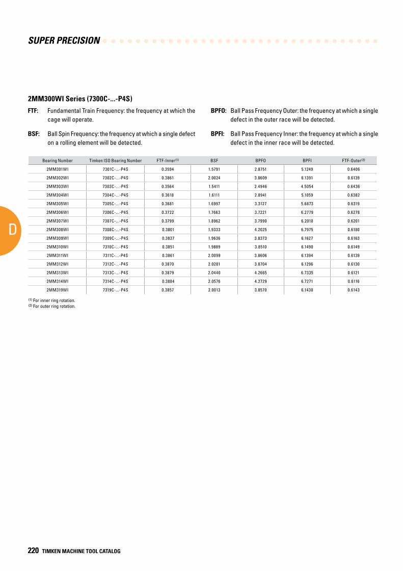
SUPER PRECISION
D
220 TIMKEN MACHINE TOOL CATALOG
Bearing Number Timken ISO Bearing Number FTF-Inner(1) BSF BPFO BPFI FTF-Outer(2)
2MM301WI 7301C-...-P4S 0.3594 1.5791 2.8751 5.1249 0.6406
2MM302WI 7302C-...-P4S 0.3861 2.0024 3.8609 6.1391 0.6139
2MM303WI 7303C-...-P4S 0.3564 1.5411 2.4946 4.5054 0.6436
2MM304WI 7304C-...-P4S 0.3618 1.6111 2.8941 5.1059 0.6382
2MM305WI 7305C-...-P4S 0.3681 1.6997 3.3127 5.6873 0.6319
2MM306WI 7306C-...-P4S 0.3722 1.7663 3.7221 6.2779 0.6278
2MM307WI 7307C-...-P4S 0.3799 1.8962 3.7990 6.2010 0.6201
2MM308WI 7308C-...-P4S 0.3801 1.9333 4.2025 6.7975 0.6180
2MM309WI 7309C-...-P4S 0.3837 1.9636 3.8373 6.1627 0.6163
2MM310WI 7310C-...-P4S 0.3851 1.9889 3.8510 6.1490 0.6149
2MM311WI 7311C-...-P4S 0.3861 2.0099 3.8606 6.1394 0.6139
2MM312WI 7312C-...-P4S 0.3870 2.0281 3.8704 6.1296 0.6130
2MM313WI 7313C-...-P4S 0.3879 2.0440 4.2665 6.7335 0.6121
2MM314WI 7314C-...-P4S 0.3884 2.0576 4.2729 6.7271 0.6116
2MM319WI 7319C-...-P4S 0.3857 2.0013 3.8570 6.1430 0.6143
(1) For inner ring rotation.(2) For outer ring rotation.
FTF: Fundamental Train Frequency: the frequency at which the cage will operate.
BSF: Ball Spin Frequency: the frequency at which a single defect on a rolling element will be detected.
BPFO: Ball Pass Frequency Outer: the frequency at which a single defect in the outer race will be detected.
BPFI: Ball Pass Frequency Inner: the frequency at which a single defect in the inner race will be detected.
2MM300WI Series (7300C-...-P4S)
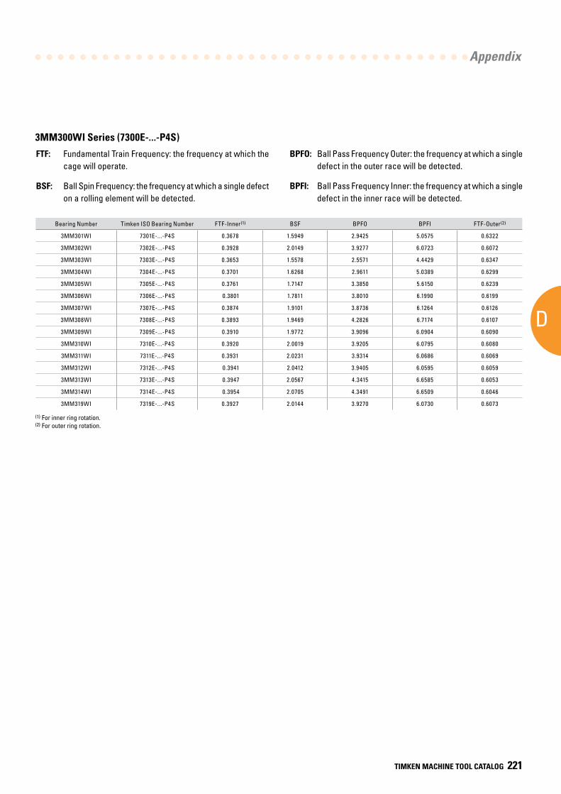
AD
Appendix
TIMKEN MACHINE TOOL CATALOG 221
Bearing Number Timken ISO Bearing Number FTF-Inner(1) BSF BPFO BPFI FTF-Outer(2)
3MM301WI 7301E-...-P4S 0.3678 1.5949 2.9425 5.0575 0.6322
3MM302WI 7302E-...-P4S 0.3928 2.0149 3.9277 6.0723 0.6072
3MM303WI 7303E-...-P4S 0.3653 1.5578 2.5571 4.4429 0.6347
3MM304WI 7304E-...-P4S 0.3701 1.6268 2.9611 5.0389 0.6299
3MM305WI 7305E-...-P4S 0.3761 1.7147 3.3850 5.6150 0.6239
3MM306WI 7306E-...-P4S 0.3801 1.7811 3.8010 6.1990 0.6199
3MM307WI 7307E-...-P4S 0.3874 1.9101 3.8736 6.1264 0.6126
3MM308WI 7308E-...-P4S 0.3893 1.9469 4.2826 6.7174 0.6107
3MM309WI 7309E-...-P4S 0.3910 1.9772 3.9096 6.0904 0.6090
3MM310WI 7310E-...-P4S 0.3920 2.0019 3.9205 6.0795 0.6080
3MM311WI 7311E-...-P4S 0.3931 2.0231 3.9314 6.0686 0.6069
3MM312WI 7312E-...-P4S 0.3941 2.0412 3.9405 6.0595 0.6059
3MM313WI 7313E-...-P4S 0.3947 2.0567 4.3415 6.6585 0.6053
3MM314WI 7314E-...-P4S 0.3954 2.0705 4.3491 6.6509 0.6046
3MM319WI 7319E-...-P4S 0.3927 2.0144 3.9270 6.0730 0.6073
(1) For inner ring rotation. (2) For outer ring rotation.
FTF: Fundamental Train Frequency: the frequency at which the cage will operate.
BSF: Ball Spin Frequency: the frequency at which a single defect on a rolling element will be detected.
BPFO: Ball Pass Frequency Outer: the frequency at which a single defect in the outer race will be detected.
BPFI: Ball Pass Frequency Inner: the frequency at which a single defect in the inner race will be detected.
3MM300WI Series (7300E-...-P4S)
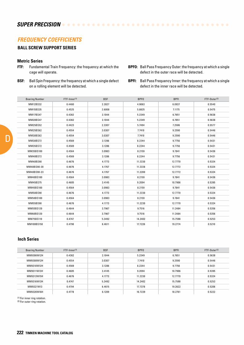
SUPER PRECISION
D
222 TIMKEN MACHINE TOOL CATALOG
Bearing Number FTF-Inner(1) BSF BPFO BPFI FTF-Outer(2)
MM12BS32 0.4460 2.2827 4.9063 6.0937 0.5540
MM15BS35 0.4525 2.6008 5.8825 7.1175 0.5475
MM17BS47 0.4362 2.1044 5.2349 6.7651 0.5638
MM20BS47 0.4362 2.1044 5.2349 6.7651 0.5638
MM25BS52 0.4423 2.3307 5.7494 7.2506 0.5577
MM25BS62 0.4554 3.0307 7.7410 9.2590 0.5446
MM30BS62 0.4554 3.0307 7.7410 9.2590 0.5446
MM30BS72 0.4569 3.1286 8.2244 9.7756 0.5431
MM35BS72 0.4569 3.1286 8.2244 9.7756 0.5431
MM35BS100 0.4564 3.0983 8.2159 9.7841 0.5436
MM40BS72 0.4569 3.1286 8.2244 9.7756 0.5431
MM40BS90 0.4676 4.1773 11.2230 12.7770 0.5324
MM40BS90-20 0.4676 4.1767 11.2228 12.7772 0.5324
MM40BS90-23 0.4676 4.1767 11.2200 12.7772 0.5324
MM40BS100 0.4564 3.0983 8.2159 9.7841 0.5436
MM45BS75 0.4605 3.4145 9.2094 10.7906 0.5395
MM45BS100 0.4564 3.0983 8.2159 9.7841 0.5436
MM50BS90 0.4676 4.1773 11.2230 12.7770 0.5324
MM50BS100 0.4564 3.0983 8.2159 9.7841 0.5436
MM55BS90 0.4676 4.1773 11.2230 12.7770 0.5324
MM55BS120 0.4644 3.7967 9.7516 11.2484 0.5356
MM60BS120 0.4644 3.7967 9.7516 11.2484 0.5356
MM75BS110 0.4747 5.3492 14.2402 15.7598 0.5253
MM100BS150 0.4790 6.4611 17.7226 19.2774 0.5210
Bearing Number FTF-Inner(1) BSF BPFO BPFI FTF-Outer(2)
MM9306WI2H 0.4362 2.1044 5.2349 6.7651 0.5638
MM9308WI2H 0.4554 3.0307 7.7410 9.2590 0.5446
MM9310WI2H 0.4569 3.1286 8.2244 9.7756 0.5431
MM9311WI3H 0.4605 3.4145 9.2094 10.7906 0.5395
MM9313WI5H 0.4676 4.1773 11.2230 12.7770 0.5324
MM9316WI3H 0.4747 5.3492 14.2402 15.7598 0.5253
MM9321WI3 0.4794 6.4615 17.7378 19.2622 0.5206
MM9326WI6H 0.4778 6.1209 16.7239 18.2761 0.5222
(1) For inner ring rotation.(2) For outer ring rotation.
FTF: Fundamental Train Frequency: the frequency at which the cage will operate.
BSF: Ball Spin Frequency: the frequency at which a single defect on a rolling element will be detected.
BPFO: Ball Pass Frequency Outer: the frequency at which a single defect in the outer race will be detected.
BPFI: Ball Pass Frequency Inner: the frequency at which a single defect in the inner race will be detected.
FREQUENCY COEFFICIENTSBALL SCREW SUPPORT SERIES
Metric Series
Inch Series
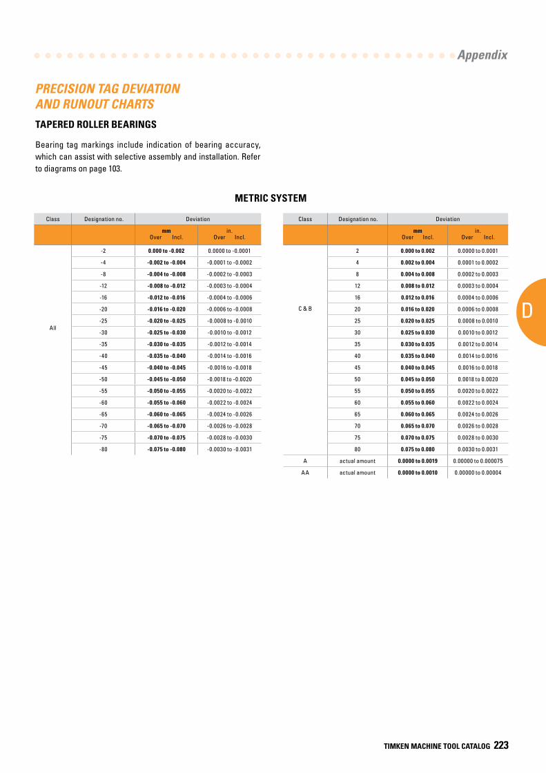
AD
Appendix
TIMKEN MACHINE TOOL CATALOG 223
PRECISION TAG DEVIATION AND RUNOUT CHARTSTAPERED ROLLER BEARINGS
Bearing tag markings include indication of bearing accuracy, which can assist with selective assembly and installation. Refer to diagrams on page 103.
METRIC SYSTEM
Class Designation no. Deviation
mmOver Incl.
in.Over Incl.
All
-2 0.000 to -0.002 0.0000 to -0.0001
-4 -0.002 to -0.004 -0.0001 to -0.0002
-8 -0.004 to -0.008 -0.0002 to -0.0003
-12 -0.008 to -0.012 -0.0003 to -0.0004
-16 -0.012 to -0.016 -0.0004 to -0.0006
-20 -0.016 to -0.020 -0.0006 to -0.0008
-25 -0.020 to -0.025 -0.0008 to -0.0010
-30 -0.025 to -0.030 -0.0010 to -0.0012
-35 -0.030 to -0.035 -0.0012 to -0.0014
-40 -0.035 to -0.040 -0.0014 to -0.0016
-45 -0.040 to -0.045 -0.0016 to -0.0018
-50 -0.045 to -0.050 -0.0018 to -0.0020
-55 -0.050 to -0.055 -0.0020 to -0.0022
-60 -0.055 to -0.060 -0.0022 to -0.0024
-65 -0.060 to -0.065 -0.0024 to -0.0026
-70 -0.065 to -0.070 -0.0026 to -0.0028
-75 -0.070 to -0.075 -0.0028 to -0.0030
-80 -0.075 to -0.080 -0.0030 to -0.0031
Class Designation no. Deviation
mmOver Incl.
in.Over Incl.
C & B
2 0.000 to 0.002 0.0000 to 0.0001
4 0.002 to 0.004 0.0001 to 0.0002
8 0.004 to 0.008 0.0002 to 0.0003
12 0.008 to 0.012 0.0003 to 0.0004
16 0.012 to 0.016 0.0004 to 0.0006
20 0.016 to 0.020 0.0006 to 0.0008
25 0.020 to 0.025 0.0008 to 0.0010
30 0.025 to 0.030 0.0010 to 0.0012
35 0.030 to 0.035 0.0012 to 0.0014
40 0.035 to 0.040 0.0014 to 0.0016
45 0.040 to 0.045 0.0016 to 0.0018
50 0.045 to 0.050 0.0018 to 0.0020
55 0.050 to 0.055 0.0020 to 0.0022
60 0.055 to 0.060 0.0022 to 0.0024
65 0.060 to 0.065 0.0024 to 0.0026
70 0.065 to 0.070 0.0026 to 0.0028
75 0.070 to 0.075 0.0028 to 0.0030
80 0.075 to 0.080 0.0030 to 0.0031
A actual amount 0.0000 to 0.0019 0.00000 to 0.000075
AA actual amount 0.0000 to 0.0010 0.00000 to 0.00004
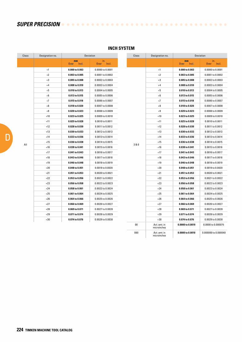
SUPER PRECISION
D
224 TIMKEN MACHINE TOOL CATALOG
Class Designation no. Deviation
mmOver Incl.
in.Over Incl.
All
+1 0.000 to 0.003 0.0000 to 0.0001
+2 0.003 to 0.005 0.0001 to 0.0002
+3 0.005 to 0.008 0.0002 to 0.0003
+4 0.008 to 0.010 0.0003 to 0.0004
+5 0.010 to 0.013 0.0004 to 0.0005
+6 0.013 to 0.015 0.0005 to 0.0006
+7 0.015 to 0.018 0.0006 to 0.0007
+8 0.018 to 0.020 0.0007 to 0.0008
+9 0.020 to 0.023 0.0008 to 0.0009
+10 0.023 to 0.025 0.0009 to 0.0010
+11 0.025 to 0.028 0.0010 to 0.0011
+12 0.028 to 0.030 0.0011 to 0.0012
+13 0.030 to 0.033 0.0012 to 0.0013
+14 0.033 to 0.036 0.0013 to 0.0014
+15 0.036 to 0.038 0.0014 to 0.0015
+16 0.038 to 0.041 0.0015 to 0.0016
+17 0.041 to 0.043 0.0016 to 0.0017
+18 0.043 to 0.046 0.0017 to 0.0018
+19 0.046 to 0.048 0.0018 to 0.0019
+20 0.048 to 0.051 0.0019 to 0.0020
+21 0.051 to 0.053 0.0020 to 0.0021
+22 0.053 to 0.056 0.0021 to 0.0022
+23 0.056 to 0.058 0.0022 to 0.0023
+24 0.058 to 0.061 0.0023 to 0.0024
+25 0.061 to 0.064 0.0024 to 0.0025
+26 0.064 to 0.066 0.0025 to 0.0026
+27 0.066 to 0.069 0.0026 to 0.0027
+28 0.069 to 0.071 0.0027 to 0.0028
+29 0.071 to 0.074 0.0028 to 0.0029
+30 0.074 to 0.076 0.0029 to 0.0030
Class Designation no. Deviation
mmOver Incl.
in.Over Incl.
3 & 0
+1 0.000 to 0.003 0.0000 to 0.0001
+2 0.003 to 0.005 0.0001 to 0.0002
+3 0.005 to 0.008 0.0002 to 0.0003
+4 0.008 to 0.010 0.0003 to 0.0004
+5 0.010 to 0.013 0.0004 to 0.0005
+6 0.013 to 0.015 0.0005 to 0.0006
+7 0.015 to 0.018 0.0006 to 0.0007
+8 0.018 to 0.020 0.0007 to 0.0008
+9 0.020 to 0.023 0.0008 to 0.0009
+10 0.023 to 0.025 0.0009 to 0.0010
+11 0.025 to 0.028 0.0010 to 0.0011
+12 0.028 to 0.030 0.0011 to 0.0012
+13 0.030 to 0.033 0.0012 to 0.0013
+14 0.033 to 0.036 0.0013 to 0.0014
+15 0.036 to 0.038 0.0014 to 0.0015
+16 0.038 to 0.041 0.0015 to 0.0016
+17 0.041 to 0.043 0.0016 to 0.0017
+18 0.043 to 0.046 0.0017 to 0.0018
+19 0.046 to 0.048 0.0018 to 0.0019
+20 0.048 to 0.051 0.0019 to 0.0020
+21 0.051 to 0.053 0.0020 to 0.0021
+22 0.053 to 0.056 0.0021 to 0.0022
+23 0.056 to 0.058 0.0022 to 0.0023
+24 0.058 to 0.061 0.0023 to 0.0024
+25 0.061 to 0.064 0.0024 to 0.0025
+26 0.064 to 0.066 0.0025 to 0.0026
+27 0.066 to 0.069 0.0026 to 0.0027
+28 0.069 to 0.071 0.0027 to 0.0028
+29 0.071 to 0.074 0.0028 to 0.0029
+30 0.074 to 0.076 0.0029 to 0.0030
00 Act. amt. in microinches
0.0000 to 0.0019 0.0000 to 0.000075
000 Act. amt. in microinches
0.0000 to 0.0010 0.000000 to 0.000040
INCH SYSTEM
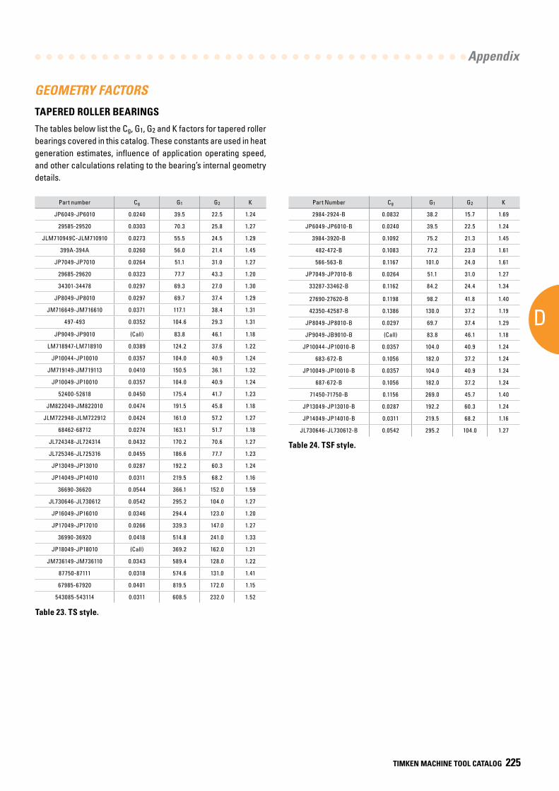
AD
Appendix
TIMKEN MACHINE TOOL CATALOG 225
GEOMETRY FACTORS
Part Number Cg G1 G2 K
2984-2924-B 0.0832 38.2 15.7 1.69
JP6049-JP6010-B 0.0240 39.5 22.5 1.24
3984-3920-B 0.1092 75.2 21.3 1.45
482-472-B 0.1083 77.2 23.0 1.61
566-563-B 0.1167 101.0 24.0 1.61
JP7049-JP7010-B 0.0264 51.1 31.0 1.27
33287-33462-B 0.1162 84.2 24.4 1.34
27690-27620-B 0.1198 98.2 41.8 1.40
42350-42587-B 0.1386 130.0 37.2 1.19
JP8049-JP8010-B 0.0297 69.7 37.4 1.29
JP9049-JB9010-B (Call) 83.8 46.1 1.18
JP10044-JP10010-B 0.0357 104.0 40.9 1.24
683-672-B 0.1056 182.0 37.2 1.24
JP10049-JP10010-B 0.0357 104.0 40.9 1.24
687-672-B 0.1056 182.0 37.2 1.24
71450-71750-B 0.1156 269.0 45.7 1.40
JP13049-JP13010-B 0.0287 192.2 60.3 1.24
JP14049-JP14010-B 0.0311 219.5 68.2 1.16
JL730646-JL730612-B 0.0542 295.2 104.0 1.27
Table 23. TS style.
Part number Cg G1 G2 K
JP6049-JP6010 0.0240 39.5 22.5 1.24
29585-29520 0.0303 70.3 25.8 1.27
JLM710949C-JLM710910 0.0273 55.5 24.5 1.29
399A-394A 0.0260 56.0 21.4 1.45
JP7049-JP7010 0.0264 51.1 31.0 1.27
29685-29620 0.0323 77.7 43.3 1.20
34301-34478 0.0297 69.3 27.0 1.30
JP8049-JP8010 0.0297 69.7 37.4 1.29
JM716649-JM716610 0.0371 117.1 38.4 1.31
497-493 0.0352 104.6 29.3 1.31
JP9049-JP9010 (Call) 83.8 46.1 1.18
LM718947-LM718910 0.0389 124.2 37.6 1.22
JP10044-JP10010 0.0357 104.0 40.9 1.24
JM719149-JM719113 0.0410 150.5 36.1 1.32
JP10049-JP10010 0.0357 104.0 40.9 1.24
52400-52618 0.0450 175.4 41.7 1.23
JM822049-JM822010 0.0474 191.5 45.8 1.18
JLM722948-JLM722912 0.0424 161.0 57.2 1.27
68462-68712 0.0274 163.1 51.7 1.18
JL724348-JL724314 0.0432 170.2 70.6 1.27
JL725346-JL725316 0.0455 186.6 77.7 1.23
JP13049-JP13010 0.0287 192.2 60.3 1.24
JP14049-JP14010 0.0311 219.5 68.2 1.16
36690-36620 0.0544 366.1 152.0 1.59
JL730646-JL730612 0.0542 295.2 104.0 1.27
JP16049-JP16010 0.0346 294.4 123.0 1.20
JP17049-JP17010 0.0266 339.3 147.0 1.27
36990-36920 0.0418 514.8 241.0 1.33
JP18049-JP18010 (Call) 369.2 162.0 1.21
JM736149-JM736110 0.0343 589.4 128.0 1.22
87750-87111 0.0318 574.6 131.0 1.41
67985-67920 0.0401 819.5 172.0 1.15
543085-543114 0.0311 608.5 232.0 1.52
TAPERED ROLLER BEARINGS
The tables below list the Cg, G1, G2 and K factors for tapered roller bearings covered in this catalog. These constants are used in heat generation estimates, influence of application operating speed, and other calculations relating to the bearing’s internal geometry details.
Table 24. TSF style.
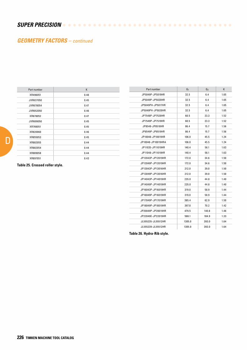
SUPER PRECISION
D
226 TIMKEN MACHINE TOOL CATALOG
Part number K
XR496051 0.48
JXR637050 0.45
JXR678054 0.47
JXR652050 0.46
XR678052 0.47
JXR699050 0.45
XR766051 0.45
XR820060 0.46
XR855053 0.45
XR882055 0.44
XR882054 0.44
XR889058 0.44
XR897051 0.43
Part number G1 G2 K
JP5049P-JP5019HR 32.5 6.4 1.65
JP5049P-JP5020HR 32.5 6.4 1.65
JP5049PH-JP5017HR 32.5 6.4 1.65
JP5049PH-JP5020HR 32.5 6.4 1.65
JP7548P-JP7520HR 60.5 23.3 1.52
JP7549P-JP7519HR 60.5 23.3 1.52
JP8548-JP8518HR 86.4 15.7 1.56
JP8549P-JP8519HR 86.4 15.7 1.56
JP10048-JP10019HR 106.0 45.5 1.24
JP10048-JP10019HRA 106.0 45.5 1.24
JP11035-JP11019HR 140.4 56.1 1.63
JP11048-JP11019HR 140.4 56.1 1.63
JP12043P-JP12019HR 172.0 34.6 1.50
JP12049P-JP12019HR 172.0 34.6 1.50
JP13043P-JP13016HR 212.0 39.0 1.50
JP13049P-JP13016HR 212.0 39.0 1.50
JP14043P-JP14019HR 235.0 44.8 1.40
JP14049P-JP14019HR 235.0 44.8 1.40
JP16043P-JP16019HR 319.0 58.9 1.44
JP16049P-JP16019HR 319.0 58.9 1.44
JP17049P-JP17019HR 365.4 62.9 1.50
JP18049P-JP18019HR 397.8 70.2 1.42
JP20049P-JP20019HR 479.5 140.8 1.46
JP22049E-JP22019HR 588.1 184.9 1.33
JL555235-JL55512HR 1305.0 393.0 1.64
JL555239-JL55512HR 1305.0 393.0 1.64
Table 25. Crossed roller style.
Table 26. Hydra-Rib style.
GEOMETRY FACTORS – continued
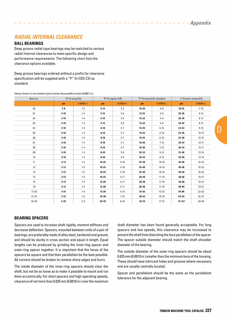
AD
Appendix
TIMKEN MACHINE TOOL CATALOG 227
Bore no. "H" fit snug (C2) "R" fit regular (C0) "P" fit loose (C3)-standard "J" fit extra-loose (C4)
µm 0.0000 in. µm 0.0000 in. µm 0.0000 in. µm 0.0000 in.
00 3-8 1-3 5-13 2-5 10-20 4-8 18-25 7-10
01 3-10 1-4 5-15 2-6 13-23 5-9 20-30 8-12
02 3-10 1-4 5-15 2-6 13-23 5-9 20-30 8-12
03 3-10 1-4 5-15 2-6 13-23 5-9 20-30 8-12
04 3-10 1-4 8-18 3-7 15-25 6-10 23-33 9-13
05 3-10 1-4 8-18 3-7 15-25 6-10 25-38 10-15
06 3-10 1-4 8-18 3-7 15-25 6-10 25-38 10-15
07 3-10 1-4 8-18 3-7 18-30 7-12 30-43 12-17
08 3-10 1-4 8-18 3-7 18-30 7-12 30-43 12-17
09 3-10 1-4 8-20 3-8 20-33 8-13 33-48 13-19
10 3-10 1-4 8-20 3-8 20-33 8-13 33-48 13-19
11 3-13 1-5 10-25 4-10 25-40 10-16 40-58 16-23
12 3-13 1-5 10-25 4-10 25-40 10-16 40-58 16-23
13 3-13 1-5 10-25 4-10 25-40 10-16 40-58 16-23
14 3-13 1-5 10-25 5-11 28-48 11-19 48-68 19-27
15 3-13 1-5 13-28 5-11 28-48 11-19 48-68 19-27
16 3-13 1-5 13-28 5-11 28-48 11-19 48-68 19-27
17-20 3-15 1-6 13-28 5-13 33-55 13-22 55-80 22-32
21-24 3-15 1-6 18-38 7-15 38-63 15-25 63-93 25-37
25-28 5-20 2-8 20-45 8-18 43-79 17-31 74-127 29-50
BEARING SPACERS
Spacers are used to increase shaft rigidity, moment stiffness and decrease deflection. Spacers, mounted between units of a pair of bearings, are preferably made of alloy steel, hardened and ground, and should be sturdy in cross section and equal in length. Equal lengths can be produced by grinding the inner-ring spacer and outer-ring spacer together. It is important that the faces of the spacers be square and that their parallelism be the best possible. All corners should be broken to remove sharp edges and burrs.
The inside diameter of the inner-ring spacers should clear the shaft, but not be so loose as to make it possible to mount and run them eccentrically. For short spacers and high operating speeds, clearance of not more than 0.025 mm (0.0010 in.) over the maximum
RADIAL INTERNAL CLEARANCEBALL BEARINGSDeep groove radial type bearings may be matched to various radial internal clearances to meet specific design and performance requirements. The following chart lists the clearance options available.
Deep groove bearings ordered without a prefix for clearance specification will be supplied with a “P” fit (ISO C3) as standard.
shaft diameter has been found generally acceptable. For long spacers and low speeds, this clearance may be increased to prevent the shaft from disturbing the face parallelism of the spacer. The spacer outside diameter should match the shaft shoulder diameter of the bearing.
The outside diameter of the outer-ring spacers should be about 0.025 mm (0.0010 in.) smaller than the minimum bore of the housing. These should have lubricant holes and grooves where necessary and are usually centrally located.
Spacer end parallelism should be the same as the parallelism tolerance for the adjacent bearing.
Values shown in micrometers (µm) and ten-thousandths inches (0.0001 in.).
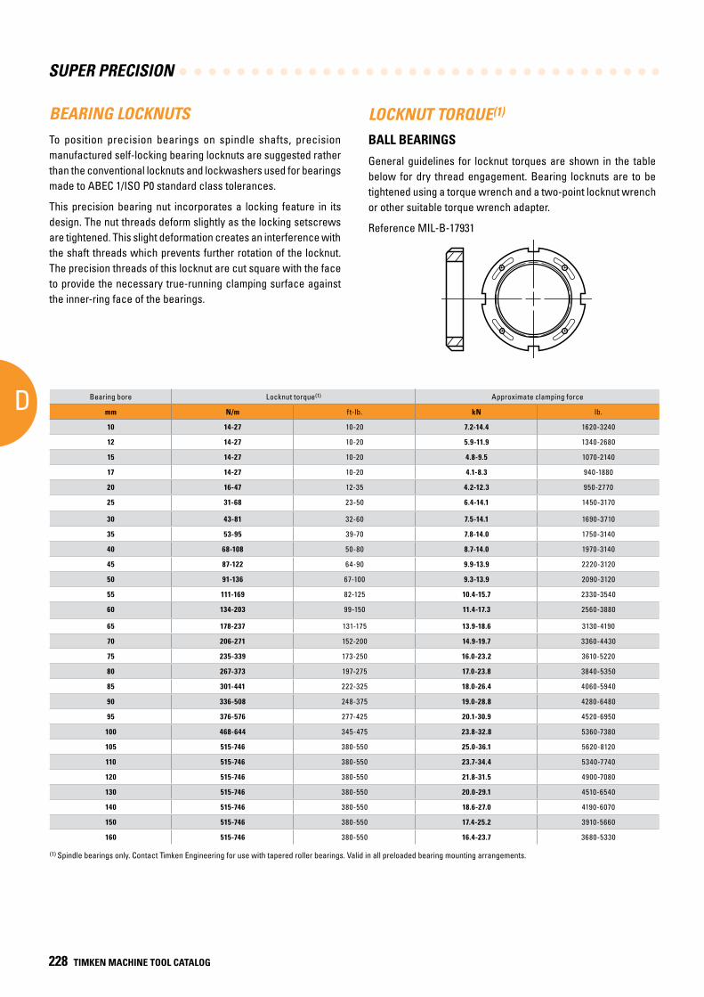
SUPER PRECISION
D
228 TIMKEN MACHINE TOOL CATALOG
BEARING LOCKNUTSTo position precision bearings on spindle shafts, precision manufactured self-locking bearing locknuts are suggested rather than the conventional locknuts and lockwashers used for bearings made to ABEC 1/ISO P0 standard class tolerances.
This precision bearing nut incorporates a locking feature in its design. The nut threads deform slightly as the locking setscrews are tightened. This slight deformation creates an interference with the shaft threads which prevents further rotation of the locknut. The precision threads of this locknut are cut square with the face to provide the necessary true-running clamping surface against the inner-ring face of the bearings.
LOCKNUT TORQUE(1)
BALL BEARINGS
General guidelines for locknut torques are shown in the table below for dry thread engagement. Bearing locknuts are to be tightened using a torque wrench and a two-point locknut wrench or other suitable torque wrench adapter.
Reference MIL-B-17931
(1) Spindle bearings only. Contact Timken Engineering for use with tapered roller bearings. Valid in all preloaded bearing mounting arrangements.
Bearing bore Locknut torque(1) Approximate clamping force
mm N/m ft-lb. kN lb.
10 14-27 10-20 7.2-14.4 1620-3240
12 14-27 10-20 5.9-11.9 1340-2680
15 14-27 10-20 4.8-9.5 1070-2140
17 14-27 10-20 4.1-8.3 940-1880
20 16-47 12-35 4.2-12.3 950-2770
25 31-68 23-50 6.4-14.1 1450-3170
30 43-81 32-60 7.5-14.1 1690-3710
35 53-95 39-70 7.8-14.0 1750-3140
40 68-108 50-80 8.7-14.0 1970-3140
45 87-122 64-90 9.9-13.9 2220-3120
50 91-136 67-100 9.3-13.9 2090-3120
55 111-169 82-125 10.4-15.7 2330-3540
60 134-203 99-150 11.4-17.3 2560-3880
65 178-237 131-175 13.9-18.6 3130-4190
70 206-271 152-200 14.9-19.7 3360-4430
75 235-339 173-250 16.0-23.2 3610-5220
80 267-373 197-275 17.0-23.8 3840-5350
85 301-441 222-325 18.0-26.4 4060-5940
90 336-508 248-375 19.0-28.8 4280-6480
95 376-576 277-425 20.1-30.9 4520-6950
100 468-644 345-475 23.8-32.8 5360-7380
105 515-746 380-550 25.0-36.1 5620-8120
110 515-746 380-550 23.7-34.4 5340-7740
120 515-746 380-550 21.8-31.5 4900-7080
130 515-746 380-550 20.0-29.1 4510-6540
140 515-746 380-550 18.6-27.0 4190-6070
150 515-746 380-550 17.4-25.2 3910-5660
160 515-746 380-550 16.4-23.7 3680-5330
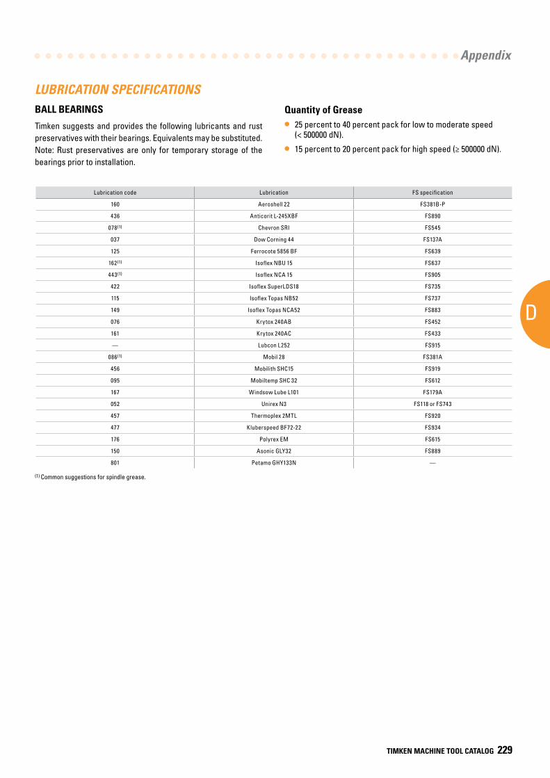
AD
Appendix
TIMKEN MACHINE TOOL CATALOG 229
LUBRICATION SPECIFICATIONSBALL BEARINGS
Timken suggests and provides the following lubricants and rust preservatives with their bearings. Equivalents may be substituted. Note: Rust preservatives are only for temporary storage of the bearings prior to installation.
(1) Common suggestions for spindle grease.
Lubrication code Lubrication FS specification
160 Aeroshell 22 FS381B-P
436 Anticorit L-245XBF FS890
078(1) Chevron SRI FS545
037 Dow Corning 44 FS137A
125 Ferrocote 5856 BF FS639
162(1) Isoflex NBU 15 FS637
443(1) Isoflex NCA 15 FS905
422 Isoflex SuperLDS18 FS735
115 Isoflex Topas NB52 FS737
149 Isoflex Topas NCA52 FS883
076 Krytox 240AB FS452
161 Krytox 240AC FS433
— Lubcon L252 FS915
086(1) Mobil 28 FS381A
456 Mobilith SHC15 FS919
095 Mobiltemp SHC 32 FS612
167 Windsow Lube L101 FS179A
052 Unirex N3 FS118 or FS743
457 Thermoplex 2MTL FS920
477 Kluberspeed BF72-22 FS934
176 Polyrex EM FS615
150 Asonic GLY32 FS889
801 Petamo GHY133N —
Quantity of Grease
• 25 percent to 40 percent pack for low to moderate speed (< 500000 dN).
• 15 percent to 20 percent pack for high speed (≥ 500000 dN).
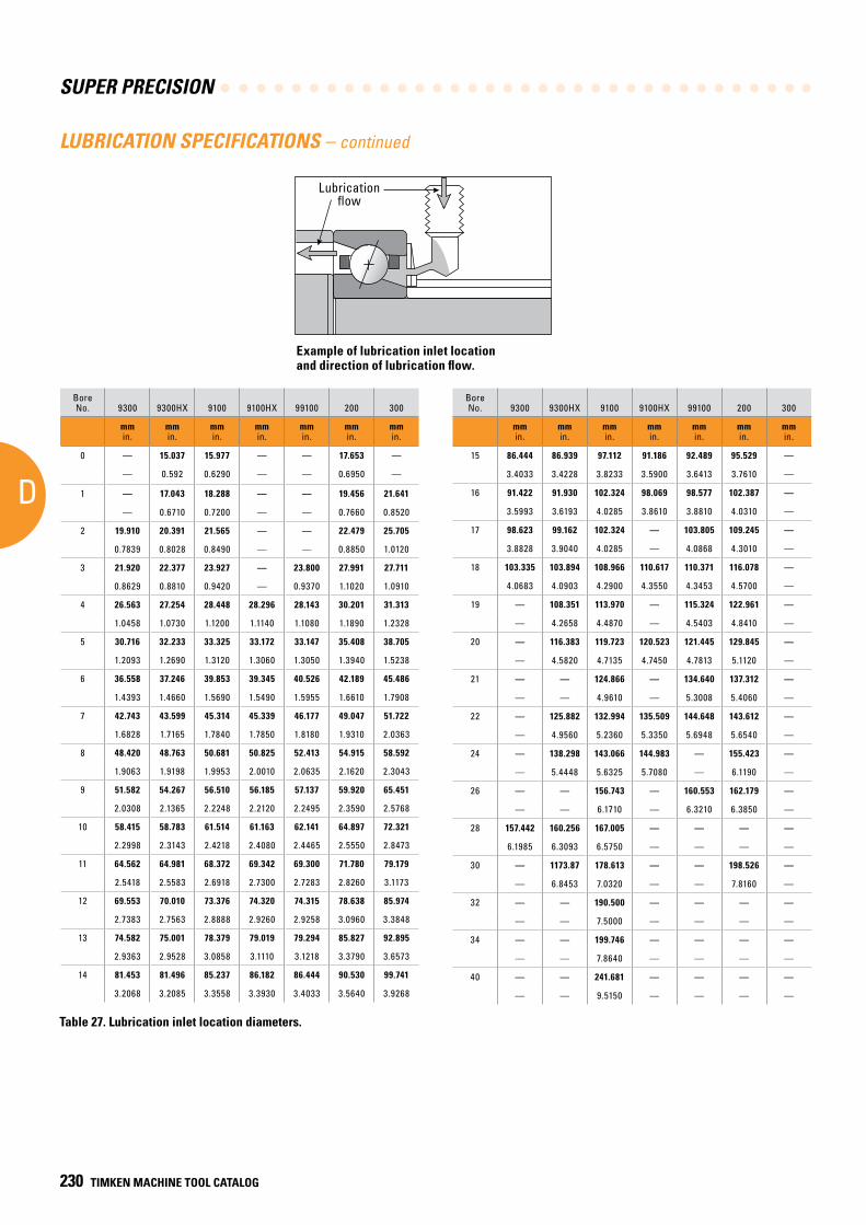
SUPER PRECISION
D
230 TIMKEN MACHINE TOOL CATALOG
Bore No. 9300 9300HX 9100 9100HX 99100 200 300
mmin.
mmin.
mmin.
mmin.
mmin.
mmin.
mmin.
0 — 15.037 15.977 — — 17.653 —
— 0.592 0.6290 — — 0.6950 —
1 — 17.043 18.288 — — 19.456 21.641
— 0.6710 0.7200 — — 0.7660 0.8520
2 19.910 20.391 21.565 — — 22.479 25.705
0.7839 0.8028 0.8490 — — 0.8850 1.0120
3 21.920 22.377 23.927 — 23.800 27.991 27.711
0.8629 0.8810 0.9420 — 0.9370 1.1020 1.0910
4 26.563 27.254 28.448 28.296 28.143 30.201 31.313
1.0458 1.0730 1.1200 1.1140 1.1080 1.1890 1.2328
5 30.716 32.233 33.325 33.172 33.147 35.408 38.705
1.2093 1.2690 1.3120 1.3060 1.3050 1.3940 1.5238
6 36.558 37.246 39.853 39.345 40.526 42.189 45.486
1.4393 1.4660 1.5690 1.5490 1.5955 1.6610 1.7908
7 42.743 43.599 45.314 45.339 46.177 49.047 51.722
1.6828 1.7165 1.7840 1.7850 1.8180 1.9310 2.0363
8 48.420 48.763 50.681 50.825 52.413 54.915 58.592
1.9063 1.9198 1.9953 2.0010 2.0635 2.1620 2.3043
9 51.582 54.267 56.510 56.185 57.137 59.920 65.451
2.0308 2.1365 2.2248 2.2120 2.2495 2.3590 2.5768
10 58.415 58.783 61.514 61.163 62.141 64.897 72.321
2.2998 2.3143 2.4218 2.4080 2.4465 2.5550 2.8473
11 64.562 64.981 68.372 69.342 69.300 71.780 79.179
2.5418 2.5583 2.6918 2.7300 2.7283 2.8260 3.1173
12 69.553 70.010 73.376 74.320 74.315 78.638 85.974
2.7383 2.7563 2.8888 2.9260 2.9258 3.0960 3.3848
13 74.582 75.001 78.379 79.019 79.294 85.827 92.895
2.9363 2.9528 3.0858 3.1110 3.1218 3.3790 3.6573
14 81.453 81.496 85.237 86.182 86.444 90.530 99.741
3.2068 3.2085 3.3558 3.3930 3.4033 3.5640 3.9268
LUBRICATION SPECIFICATIONS – continued
Table 27. Lubrication inlet location diameters.
Bore No. 9300 9300HX 9100 9100HX 99100 200 300
mmin.
mmin.
mmin.
mmin.
mmin.
mmin.
mmin.
15 86.444 86.939 97.112 91.186 92.489 95.529 —
3.4033 3.4228 3.8233 3.5900 3.6413 3.7610 —
16 91.422 91.930 102.324 98.069 98.577 102.387 —
3.5993 3.6193 4.0285 3.8610 3.8810 4.0310 —
17 98.623 99.162 102.324 — 103.805 109.245 —
3.8828 3.9040 4.0285 — 4.0868 4.3010 —
18 103.335 103.894 108.966 110.617 110.371 116.078 —
4.0683 4.0903 4.2900 4.3550 4.3453 4.5700 —
19 — 108.351 113.970 — 115.324 122.961 —
— 4.2658 4.4870 — 4.5403 4.8410 —
20 — 116.383 119.723 120.523 121.445 129.845 —
— 4.5820 4.7135 4.7450 4.7813 5.1120 —
21 — — 124.866 — 134.640 137.312 —
— — 4.9610 — 5.3008 5.4060 —
22 — 125.882 132.994 135.509 144.648 143.612 —
— 4.9560 5.2360 5.3350 5.6948 5.6540 —
24 — 138.298 143.066 144.983 — 155.423 —
— 5.4448 5.6325 5.7080 — 6.1190 —
26 — — 156.743 — 160.553 162.179 —
— — 6.1710 — 6.3210 6.3850 —
28 157.442 160.256 167.005 — — — —
6.1985 6.3093 6.5750 — — — —
30 — 1173.87 178.613 — — 198.526 —
— 6.8453 7.0320 — — 7.8160 —
32 — — 190.500 — — — —
— — 7.5000 — — — —
34 — — 199.746 — — — —
— — 7.8640 — — — —
40 — — 241.681 — — — —
— — 9.5150 — — — —
Example of lubrication inlet location and direction of lubrication flow.
Lubricationflow
Lubrication flow
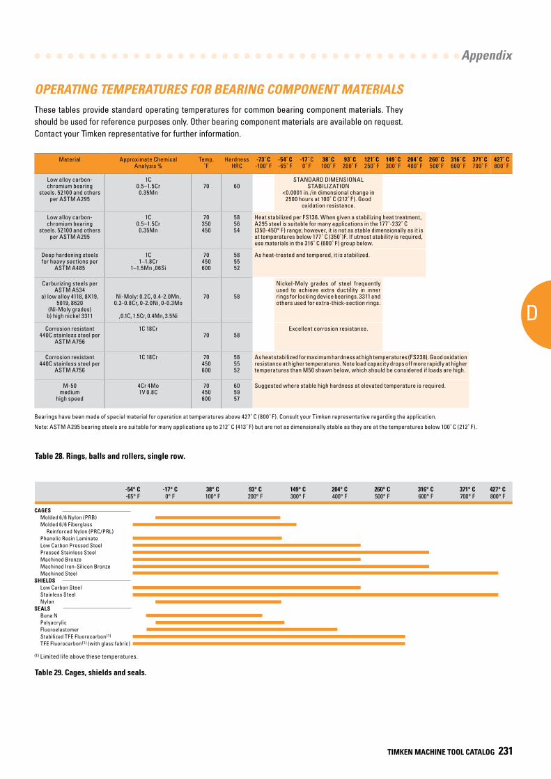
AD
Appendix
TIMKEN MACHINE TOOL CATALOG 231
Material Approximate Chemical Analysis %
Temp.˚F
HardnessHRC
-73˚ C-100˚ F
-54˚ C-65˚ F
-17˚ C0˚ F
38˚ C100˚ F
93˚ C200˚ F
121˚ C250˚ F
149˚ C300˚ F
204˚ C400˚ F
260˚ C500˚F
316˚ C600˚ F
371˚ C700˚ F
427˚ C800˚ F
Low alloy carbon- chromium bearing
steels. 52100 and others per ASTM A295
1C0.5–1.5Cr0.35Mn
70 60STANDARD DIMENSIONAL
STABILIZATION<0.0001 in./in dimensional change in
2500 hours at 100˚ C (212˚ F). Good oxidation resistance.
Low alloy carbon- chromium bearing
steels. 52100 and others per ASTM A295
1C0.5–1.5Cr0.35Mn
70350450
585654
Heat stabilized per FS136. When given a stabilizing heat treatment, A295 steel is suitable for many applications in the 177˚-232˚ C (350-450° F) range; however, it is not as stable dimensionally as it is at temperatures below 177˚ C (350˚)F. If utmost stability is required, use materials in the 316˚ C (600˚ F) group below.
Deep hardening steels for heavy sections per
ASTM A485
1C 1–1.8Cr
1–1.5Mn ,06Si
70450600
585552
As heat-treated and tempered, it is stabilized.
Carburizing steels per ASTM A534
a) low alloy 4118, 8X19, 5019, 8620
(Ni-Moly grades) b) high nickel 3311
Ni-Moly: 0.2C, 0.4-2.0Mn, 0.3-0.8Cr, 0-2.0Ni, 0-0.3Mo
,0.1C, 1.5Cr, 0.4Mn, 3.5Ni
70 58
Nickel-Moly grades of steel frequently used to achieve extra ductility in inner rings for locking device bearings. 3311 and others used for extra-thick-section rings.
Corrosion resistant 440C stainless steel per
ASTM A756
1C 18Cr70 58
Excellent corrosion resistance.
Corrosion resistant 440C stainless steel per
ASTM A756
1C 18Cr 70450600
585552
As heat stabilized for maximum hardness at high temperatures (FS238). Good oxidation resistance at higher temperatures. Note load capacity drops off more rapidly at higher temperatures than M50 shown below, which should be considered if loads are high.
M-50 medium
high speed
4Cr 4Mo1V 0.8C
70450600
605957
Suggested where stable high hardness at elevated temperature is required.
OPERATING TEMPERATURES FOR BEARING COMPONENT MATERIALSThese tables provide standard operating temperatures for common bearing component materials. They should be used for reference purposes only. Other bearing component materials are available on request. Contact your Timken representative for further information.
CAGES Molded 6/6 Nylon (PRB) Molded 6/6 Fiberglass Reinforced Nylon (PRC/PRL) Phenolic Resin Laminate Low Carbon Pressed Steel Pressed Stainless Steel Machined Bronze Machined Iron-Silicon Bronze Machined SteelSHIELDS Low Carbon Steel Stainless Steel NylonSEALS Buna N Polyacrylic Fluoroelastomer Stabilized TFE Fluorocarbon(1)
TFE Fluorocarbon(1) (with glass fabric)
-54° C -17° C 38° C 93° C 149° C 204° C 260° C 316° C 371° C 427° C -65° F 0° F 100° F 200° F 300° F 400° F 500° F 600° F 700° F 800° F
Table 29. Cages, shields and seals.
Table 28. Rings, balls and rollers, single row.
(1) Limited life above these temperatures.
Bearings have been made of special material for operation at temperatures above 427˚ C (800˚ F). Consult your Timken representative regarding the application.
Note: ASTM A295 bearing steels are suitable for many applications up to 212˚ C (413˚ F) but are not as dimensionally stable as they are at the temperatures below 100˚ C (212˚ F).
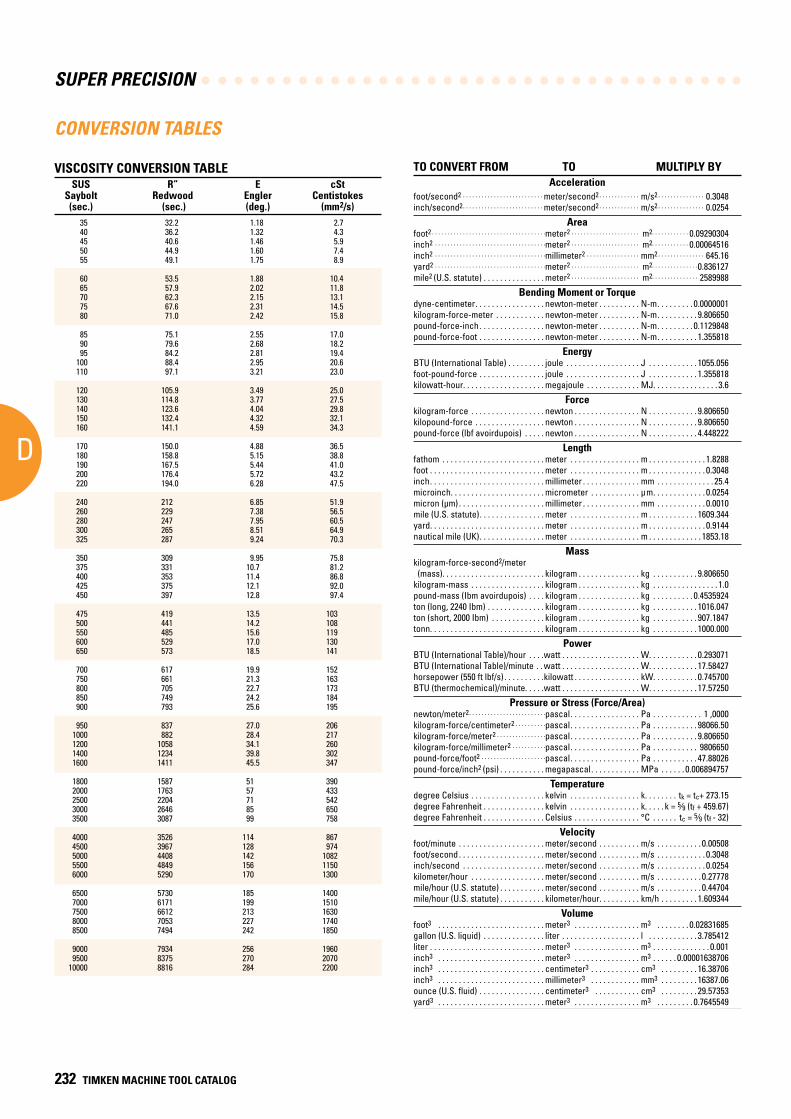
SUPER PRECISION
D
232 TIMKEN MACHINE TOOL CATALOG
VISCOSITY CONVERSION TABLE SUS R” E cSt Saybolt Redwood Engler Centistokes (sec.) (sec.) (deg.) (mm2/s) 35 32.2 1.18 2.7 40 36.2 1.32 4.3 45 40.6 1.46 5.9 50 44.9 1.60 7.4 55 49.1 1.75 8.9 60 53.5 1.88 10.4 65 57.9 2.02 11.8 70 62.3 2.15 13.1 75 67.6 2.31 14.5 80 71.0 2.42 15.8
85 75.1 2.55 17.0 90 79.6 2.68 18.2 95 84.2 2.81 19.4 100 88.4 2.95 20.6 110 97.1 3.21 23.0
120 105.9 3.49 25.0 130 114.8 3.77 27.5 140 123.6 4.04 29.8 150 132.4 4.32 32.1 160 141.1 4.59 34.3
170 150.0 4.88 36.5 180 158.8 5.15 38.8 190 167.5 5.44 41.0 200 176.4 5.72 43.2 220 194.0 6.28 47.5
240 212 6.85 51.9 260 229 7.38 56.5 280 247 7.95 60.5 300 265 8.51 64.9 325 287 9.24 70.3
350 309 9.95 75.8 375 331 10.7 81.2 400 353 11.4 86.8 425 375 12.1 92.0 450 397 12.8 97.4
475 419 13.5 103 500 441 14.2 108 550 485 15.6 119 600 529 17.0 130 650 573 18.5 141
700 617 19.9 152 750 661 21.3 163 800 705 22.7 173 850 749 24.2 184 900 793 25.6 195
950 837 27.0 206 1000 882 28.4 217 1200 1058 34.1 260 1400 1234 39.8 302 1600 1411 45.5 347
1800 1587 51 390 2000 1763 57 433 2500 2204 71 542 3000 2646 85 650 3500 3087 99 758
4000 3526 114 867 4500 3967 128 974 5000 4408 142 1082 5500 4849 156 1150 6000 5290 170 1300
6500 5730 185 1400 7000 6171 199 1510 7500 6612 213 1630 8000 7053 227 1740 8500 7494 242 1850
9000 7934 256 1960 9500 8375 270 2070 10000 8816 284 2200
CONVERSION TABLES
TO CONVERT FROM TO MULTIPLY BYAcceleration
foot/second2 . . . . . . . . . . . . . . . . . . . . . . . . . . meter/second2 . . . . . . . . . . . . . m/s2 . . . . . . . . . . . . . . . 0.3048 inch/second2 . . . . . . . . . . . . . . . . . . . . . . . . . . meter/second2 . . . . . . . . . . . . . m/s2 . . . . . . . . . . . . . . . 0.0254
Areafoot2 . . . . . . . . . . . . . . . . . . . . . . . . . . . . . . . . . . . . .meter2 . . . . . . . . . . . . . . . . . . . . . . m2. . . . . . . . . . . . 0.09290304 inch2 . . . . . . . . . . . . . . . . . . . . . . . . . . . . . . . . . . . .meter2 . . . . . . . . . . . . . . . . . . . . . . m2. . . . . . . . . . . . 0.00064516 inch2 . . . . . . . . . . . . . . . . . . . . . . . . . . . . . . . . . . . .millimeter2 . . . . . . . . . . . . . . . . . mm2 . . . . . . . . . . . . . . . 645.16 yard2 . . . . . . . . . . . . . . . . . . . . . . . . . . . . . . . . . . . .meter2 . . . . . . . . . . . . . . . . . . . . . . m2. . . . . . . . . . . . . . .0.836127 mile2 (U.S. statute) . . . . . . . . . . . . . . . meter2 . . . . . . . . . . . . . . . . . . . . . . m2. . . . . . . . . . . . . . . 2589988
Bending Moment or Torquedyne-centimeter . . . . . . . . . . . . . . . . . newton-meter . . . . . . . . . . N-m . . . . . . . . . 0.0000001 kilogram-force-meter . . . . . . . . . . . . newton-meter . . . . . . . . . . N-m . . . . . . . . . . 9.806650 pound-force-inch . . . . . . . . . . . . . . . . newton-meter . . . . . . . . . . N-m . . . . . . . . . 0.1129848 pound-force-foot . . . . . . . . . . . . . . . . newton-meter . . . . . . . . . . N-m . . . . . . . . . . 1.355818
EnergyBTU (International Table) . . . . . . . . . joule . . . . . . . . . . . . . . . . . . J . . . . . . . . . . . . 1055.056 foot-pound-force . . . . . . . . . . . . . . . . joule . . . . . . . . . . . . . . . . . . J . . . . . . . . . . . . 1.355818 kilowatt-hour. . . . . . . . . . . . . . . . . . . . megajoule . . . . . . . . . . . . . MJ. . . . . . . . . . . . . . . . 3.6
Forcekilogram-force . . . . . . . . . . . . . . . . . . newton . . . . . . . . . . . . . . . . N . . . . . . . . . . . . 9.806650 kilopound-force . . . . . . . . . . . . . . . . . newton . . . . . . . . . . . . . . . . N . . . . . . . . . . . . 9.806650 pound-force (lbf avoirdupois) . . . . . newton . . . . . . . . . . . . . . . . N . . . . . . . . . . . . 4.448222
Lengthfathom . . . . . . . . . . . . . . . . . . . . . . . . . meter . . . . . . . . . . . . . . . . . m . . . . . . . . . . . . . . 1.8288 foot . . . . . . . . . . . . . . . . . . . . . . . . . . . . meter . . . . . . . . . . . . . . . . . m . . . . . . . . . . . . . . 0.3048 inch . . . . . . . . . . . . . . . . . . . . . . . . . . . . millimeter . . . . . . . . . . . . . . mm . . . . . . . . . . . . . . 25.4 microinch. . . . . . . . . . . . . . . . . . . . . . . micrometer . . . . . . . . . . . . µm . . . . . . . . . . . . . 0.0254 micron (µm) . . . . . . . . . . . . . . . . . . . . . millimeter . . . . . . . . . . . . . . mm . . . . . . . . . . . . 0.0010 mile (U.S. statute) . . . . . . . . . . . . . . . . meter . . . . . . . . . . . . . . . . . m . . . . . . . . . . . . 1609.344 yard. . . . . . . . . . . . . . . . . . . . . . . . . . . . meter . . . . . . . . . . . . . . . . . m . . . . . . . . . . . . . . 0.9144 nautical mile (UK) . . . . . . . . . . . . . . . . meter . . . . . . . . . . . . . . . . . m . . . . . . . . . . . . . 1853.18
Masskilogram-force-second2/meter (mass). . . . . . . . . . . . . . . . . . . . . . . . . kilogram . . . . . . . . . . . . . . . kg . . . . . . . . . . . 9.806650 kilogram-mass . . . . . . . . . . . . . . . . . . kilogram . . . . . . . . . . . . . . . kg . . . . . . . . . . . . . . . . 1.0 pound-mass (Ibm avoirdupois) . . . . kilogram . . . . . . . . . . . . . . . kg . . . . . . . . . . 0.4535924 ton (long, 2240 Ibm) . . . . . . . . . . . . . . kilogram . . . . . . . . . . . . . . . kg . . . . . . . . . . . 1016.047 ton (short, 2000 Ibm) . . . . . . . . . . . . . kilogram . . . . . . . . . . . . . . . kg . . . . . . . . . . . 907.1847 tonn. . . . . . . . . . . . . . . . . . . . . . . . . . . . kilogram . . . . . . . . . . . . . . . kg . . . . . . . . . . . 1000.000
PowerBTU (International Table)/hour . . . .watt . . . . . . . . . . . . . . . . . . . W. . . . . . . . . . . . 0.293071 BTU (International Table)/minute . . watt . . . . . . . . . . . . . . . . . . . W. . . . . . . . . . . . 17.58427 horsepower (550 ft lbf/s) . . . . . . . . . .kilowatt . . . . . . . . . . . . . . . . kW. . . . . . . . . . . 0.745700 BTU (thermochemical)/minute. . . . .watt . . . . . . . . . . . . . . . . . . . W. . . . . . . . . . . . 17.57250
Pressure or Stress (Force/Area)newton/meter2 . . . . . . . . . . . . . . . . . . . . . . . . .pascal . . . . . . . . . . . . . . . . . Pa . . . . . . . . . . . . 1 ,0000 kilogram-force/centimeter2 . . . . . . . . . .pascal . . . . . . . . . . . . . . . . . Pa . . . . . . . . . . . 98066.50 kilogram-force/meter2 . . . . . . . . . . . . . . . .pascal . . . . . . . . . . . . . . . . . Pa . . . . . . . . . . . 9.806650 kilogram-force/millimeter2 . . . . . . . . . . .pascal . . . . . . . . . . . . . . . . . Pa . . . . . . . . . . . 9806650 pound-force/foot2 . . . . . . . . . . . . . . . . . . . . .pascal . . . . . . . . . . . . . . . . . Pa . . . . . . . . . . . 47.88026 pound-force/inch2 (psi) . . . . . . . . . . . megapascal . . . . . . . . . . . . MPa . . . . . . 0.006894757
Temperaturedegree Celsius . . . . . . . . . . . . . . . . . . kelvin . . . . . . . . . . . . . . . . . k. . . . . . . . tk = tc+ 273.15 degree Fahrenheit . . . . . . . . . . . . . . . kelvin . . . . . . . . . . . . . . . . . k. . . . . k = 5⁄9 (tf + 459.67) degree Fahrenheit . . . . . . . . . . . . . . . Celsius . . . . . . . . . . . . . . . . °C . . . . . . tc = 5⁄9 (tf - 32)
Velocityfoot/minute . . . . . . . . . . . . . . . . . . . . . meter/second . . . . . . . . . . m/s . . . . . . . . . . . 0.00508 foot/second . . . . . . . . . . . . . . . . . . . . . meter/second . . . . . . . . . . m/s . . . . . . . . . . . . 0.3048 inch/second . . . . . . . . . . . . . . . . . . . . meter/second . . . . . . . . . . m/s . . . . . . . . . . . . 0.0254 kilometer/hour . . . . . . . . . . . . . . . . . . meter/second . . . . . . . . . . m/s . . . . . . . . . . . 0.27778 mile/hour (U.S. statute) . . . . . . . . . . . meter/second . . . . . . . . . . m/s . . . . . . . . . . . 0.44704 mile/hour (U.S. statute) . . . . . . . . . . . kilometer/hour . . . . . . . . . . km/h . . . . . . . . . 1.609344
Volumefoot3 . . . . . . . . . . . . . . . . . . . . . . . . . . meter3 . . . . . . . . . . . . . . . . m3 . . . . . . . . 0.02831685 gallon (U.S. liquid) . . . . . . . . . . . . . . . liter . . . . . . . . . . . . . . . . . . . l . . . . . . . . . . . . 3.785412 liter . . . . . . . . . . . . . . . . . . . . . . . . . . . . meter3 . . . . . . . . . . . . . . . . m3 . . . . . . . . . . . . . . 0.001 inch3 . . . . . . . . . . . . . . . . . . . . . . . . . . meter3 . . . . . . . . . . . . . . . . m3 . . . . . . 0.00001638706 inch3 . . . . . . . . . . . . . . . . . . . . . . . . . . centimeter3 . . . . . . . . . . . . cm3 . . . . . . . . . 16.38706 inch3 . . . . . . . . . . . . . . . . . . . . . . . . . . millimeter3 . . . . . . . . . . . . mm3 . . . . . . . . . 16387.06 ounce (U.S. fluid) . . . . . . . . . . . . . . . . centimeter3 . . . . . . . . . . . cm3 . . . . . . . . . 29.57353 yard3 . . . . . . . . . . . . . . . . . . . . . . . . . . meter3 . . . . . . . . . . . . . . . . m3 . . . . . . . . . 0.7645549
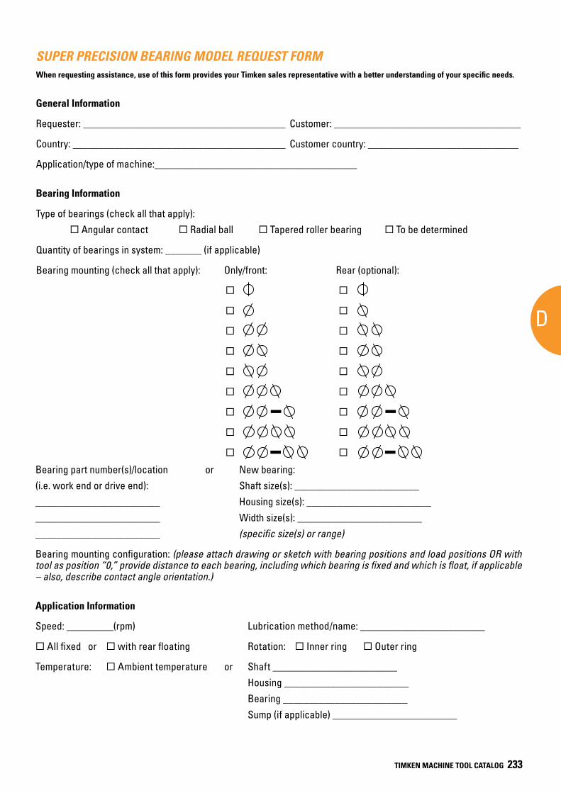
AD
Appendix
TIMKEN MACHINE TOOL CATALOG 233
SUPER PRECISION BEARING MODEL REQUEST FORMWhen requesting assistance, use of this form provides your Timken sales representative with a better understanding of your specific needs.
General Information
Requester: _______________________________________ Customer: ____________________________________
Country: _________________________________________ Customer country: _____________________________
Application/type of machine:_______________________________________
Bearing Information
Type of bearings (check all that apply): ¨ Angular contact ¨ Radial ball ¨ Tapered roller bearing ¨ To be determined
Quantity of bearings in system: _______ (if applicable)
Bearing mounting (check all that apply): Only/front: Rear (optional):
¨ ¨
¨ ¨
¨ ¨
¨ ¨
¨ ¨
¨ ¨
¨ ¨
¨ ¨
¨ ¨
Bearing part number(s)/location or New bearing: (i.e. work end or drive end): Shaft size(s): ________________________ ________________________ Housing size(s): ________________________________________________ Width size(s): ________________________________________________ (specific size(s) or range)
Bearing mounting configuration: (please attach drawing or sketch with bearing positions and load positions OR with tool as position “0,” provide distance to each bearing, including which bearing is fixed and which is float, if applicable – also, describe contact angle orientation.)
Application Information
Speed: _________(rpm) Lubrication method/name: ________________________
¨ All fixed or ̈ with rear floating Rotation: ¨ Inner ring ¨ Outer ring
Temperature: ̈ Ambient temperature or Shaft ________________________ Housing ________________________ Bearing ________________________ Sump (if applicable) ________________________
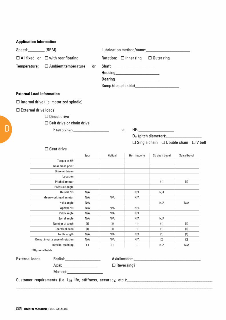
SUPER PRECISION
D
234 TIMKEN MACHINE TOOL CATALOG
Application Information
Speed:________ (RPM) Lubrication method/name:_____________________
¨ All fixed or ̈ with rear floating Rotation: ¨ Inner ring ¨ Outer ring
Temperature: ̈ Ambient temperature or Shaft_____________________ Housing_____________________ Bearing_____________________ Sump (if applicable)_____________________
External Load Information
¨ Internal drive (i.e. motorized spindle)
¨ External drive loads ̈ Direct drive ̈ Belt drive or chain drive F belt or chain:_________________ or HP:_________________ Dm (pitch diameter):_________________ ̈ Single chain ¨ Double chain ¨ V belt ̈ Gear drive
External loads Radial:_________________ Axial location: ________________________________ Axial:_________________ ̈ Reversing? Moment:_________________
Customer requirements (i.e. L10 life, stiffness, accuracy, etc.):____________________________________________________________________________________________ ________________________________________________________________________
Spur Helical Herringbone Straight bevel Spiral bevel
Torque or HP
Gear mesh point
Drive or driven
Location
Pitch diameter (1) (1)
Pressure angle
Hand (L/R) N/A N/A N/A
Mean working diameter N/A N/A N/A
Helix angle N/A N/A N/A
Apex (L/R) N/A N/A N/A
Pitch angle N/A N/A N/A
Spiral angle N/A N/A N/A N/A
Number of teeth (1) (1) (1) (1) (1)
Gear thickness (1) (1) (1) (1) (1)
Tooth length N/A N/A N/A (1) (1)
Do not invert sense of rotation N/A N/A N/A ¨ ¨
Internal meshing ¨ ¨ ¨ N/A N/A(1)Optional fields.
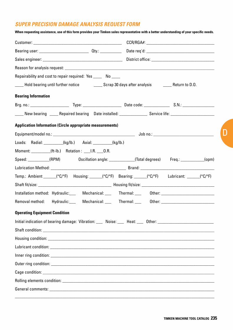
AD
Appendix
TIMKEN MACHINE TOOL CATALOG 235
SUPER PRECISION DAMAGE ANALYSIS REQUEST FORMWhen requesting assistance, use of this form provides your Timken sales representative with a better understanding of your specific needs.
Customer: _________________________________________ CCR/RGA#: ________________________________
Bearing user: _______________________ Qty.: __________ Date req'd: ________________________________
Sales engineer: _____________________________________ District office: ______________________________
Reason for analysis request: ______________________________________________________________________
Repairability and cost to repair required: Yes ____ No ____
____ Hold bearing until further notice ____ Scrap 30 days after analysis ____ Return to D.O.
Bearing Information
Brg. no.: __________________ Type: __________________ Date code: ____________ S.N.: ________________
____ New bearing ____ Repaired bearing Date installed: _____________ Service life: _____________________
Application Information (Circle appropriate measurements)
Equipment/model no.: ______________________________________ Job no.: ____________________________
Loads: Radial: _________(kg/lb.) Axial: _________(kg/lb.)
Moment: _________(ft-lb.) Rotation : ___I.R. ___O.R.
Speed: __________(RPM) Oscillation angle: ____________(Total degrees) Freq.: ___________(opm)
Lubrication Method: ___________________________________ Brand: ___________________________________
Temp.: Ambient ______(°C/°F) Housing: ______(°C/°F) Bearing: ______(°C/°F) Lubricant: ______(°C/°F)
Shaft fit/size: __________________________________ Housing fit/size: __________________________________
Installation method: Hydraulic:___ Mechanical: ___ Thermal: ___ Other: _________________________
Removal method: Hydraulic:___ Mechanical: ___ Thermal: ___ Other: _________________________
Operating Equipment Condition
Initial indication of bearing damage: Vibration: ___ Noise: ___ Heat: ___ Other: __________________________
Shaft condition: ________________________________________________________________________________
Housing condition: ______________________________________________________________________________
Lubricant condition: _____________________________________________________________________________
Inner ring condition: ____________________________________________________________________________
Outer ring condition: ____________________________________________________________________________
Cage condition: ________________________________________________________________________________
Rolling elements condition: _______________________________________________________________________
General comments: _____________________________________________________________________________
_____________________________________________________________________________________________
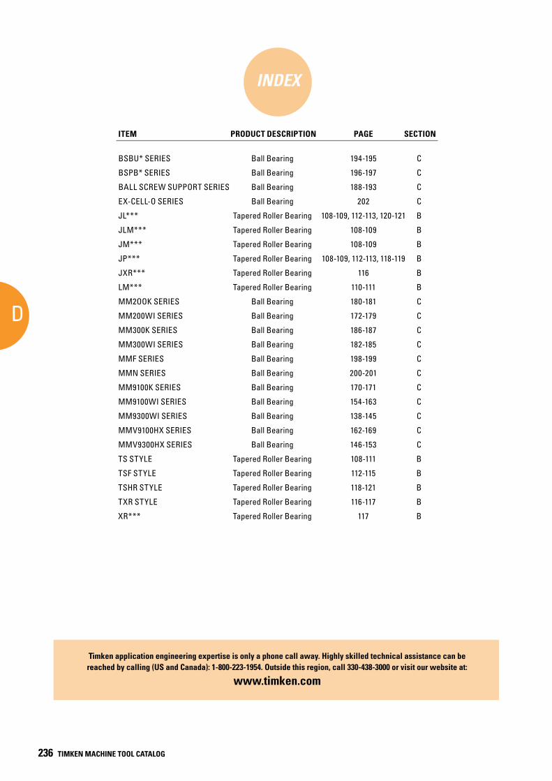
SUPER PRECISION
D
236 TIMKEN MACHINE TOOL CATALOG
INDEX
ITEM PRODUCT DESCRIPTION PAGE SECTION
BSBU* SERIES Ball Bearing 194-195 C
BSPB* SERIES Ball Bearing 196-197 C
BALL SCREW SUPPORT SERIES Ball Bearing 188-193 C
EX-CELL-O SERIES Ball Bearing 202 C
JL*** Tapered Roller Bearing 108-109, 112-113, 120-121 B
JLM*** Tapered Roller Bearing 108-109 B
JM*** Tapered Roller Bearing 108-109 B
JP*** Tapered Roller Bearing 108-109, 112-113, 118-119 B
JXR*** Tapered Roller Bearing 116 B
LM*** Tapered Roller Bearing 110-111 B
MM2OOK SERIES Ball Bearing 180-181 C
MM200WI SERIES Ball Bearing 172-179 C
MM300K SERIES Ball Bearing 186-187 C
MM300WI SERIES Ball Bearing 182-185 C
MMF SERIES Ball Bearing 198-199 C
MMN SERIES Ball Bearing 200-201 C
MM9100K SERIES Ball Bearing 170-171 C
MM9100WI SERIES Ball Bearing 154-163 C
MM9300WI SERIES Ball Bearing 138-145 C
MMV9100HX SERIES Ball Bearing 162-169 C
MMV9300HX SERIES Ball Bearing 146-153 C
TS STYLE Tapered Roller Bearing 108-111 B
TSF STYLE Tapered Roller Bearing 112-115 B
TSHR STYLE Tapered Roller Bearing 118-121 B
TXR STYLE Tapered Roller Bearing 116-117 B
XR*** Tapered Roller Bearing 117 B
Timken application engineering expertise is only a phone call away. Highly skilled technical assistance can be reached by calling (US and Canada): 1-800-223-1954. Outside this region, call 330-438-3000 or visit our website at:
www.timken.com

Price: USD $75
www.timken.com
To view more Timken catalogs, go to www.timken.com/catalogs for interactive versions, or to download a catalog app for your smart phone or mobile device scan the QR code or go to timkencatalogs.squawqr.com.
The Timken team applies their know-how to improve the reliability and performance of machinery in diverse markets worldwide. The company designs, makes and markets high-performance mechanical components, including bearings, belts, chain, gears and related mechanical power transmission products and services.
500
12-1
6 :2
9 O
rder
No.
591
8 | T
imke
n® a
nd F
afni
r® a
re re
gist
ered
trad
emar
ks o
f The
Tim
ken
Com
pany
. | ©
201
6 Th
e Ti
mke
n Co
mpa
ny |
Prin
ted
in U
.S.A
.