super phantom s2 rovsuper phantom s2 rov user’s guide 3 . introduction . this remotely operated...
TRANSCRIPT
Super Phantom S2 Remotely Operated Vehicle
User’s Guide
Undersea Vehicles Program University of North Carolina at Wilmington
5600 Marvin Moss Lane Wilmington, NC 28409 http://www.uncw.edu/uvp
Jason White Eric Glidden Operations Director/Pilot Pilot/Technician
910-962-2317 910-962-2443 [email protected] [email protected]
Super Phantom S2 ROV User’s Guide
2
Table of Contents
Introduction ....................................................................................................................................... 3
Vehicle Description .......................................................................................................................... 3
Basic Shipboard Requirements ........................................................................................................ 4
Cameras and Lights ..................................................................................................................... 5 Color Video .......................................................................................................................... 5 Digital Still Photographs ............................................................................................................ 5 Monochrome Low Light Camera .............................................................................................. 6 Dual Red Laser Scaling Device ................................................................................................. 6 Lights ........................................................................................................................................... 6
Video Recording ............................................................................................................................... 7
Navigation and Tracking .................................................................................................................. 8 Navigation Files and Video/Digital Stills Geo-referencing..................................................... 9
Data Acquisition and Sampling Tools ........................................................................................ 10 Datasonics DPL-275A Pinger Locator ..................................................................................... 10 Imagenex 881 Digital Sector-Scanning Sonar ...................................................................... 10 Benthos Single-Function Manipulator ...................................................................................... 10 Tritech PA500 Altimeter ........................................................................................................... 10 Spare Wires ................................................................................................................................. 10
Tether Management and Penetrations ............................................................................................. 11 Vessel at Anchor ......................................................................................................................... 11 ROV Free Swimming With Tether Marked by Surface Buoy ............................................... 11 ROV Towed Using Down Weight ............................................................................................ 12 ROV Free Swimming Using Down Weight ............................................................................ 12
Typical Work Day....................................................................................................................... 13
Results and Deliverables .................................................................................................................. 13
Day Rate Charges ............................................................................................................................. 13
Super Phantom S2 ROV User’s Guide
3
INTRODUCTION
This remotely operated vehicle (ROV) guide is designed to provide guidelines for the use of the Super Phantom S2 ROV system operated by the Undersea Vehicles Program at the University of North Carolina at Wilmington (UVP/UNCW). Following these guidelines will ensure the safe performance of ROV research operations for the equipment and personnel involved. This guide is to be used for mission planning and implementation in conjunction with direct consultation with the UVP/UNCW office. Every effort shall be made to complete the scientific task proposed by the Principal Investigator without placing the vehicle in jeopardy. In order to do this, all scientific requirements shall be thoroughly discussed and planned with the Principal Investigator to maximize efficiency and the successful completion of the mission objectives. Ultimate responsibility for vehicle and personnel safety rests with the ROV supervisor/operator. Therefore, it is the supervisor/operator's responsibility and duty to refuse to commit the ROV if conditions are unsafe, unfavorable, or they would be violating the conditions of their training or the regulations of the UVP/UNCW ROV Operations and Procedures Manual.
VEHICLE DESCRIPTION
The Super Phantom S2 is a powerful, versatile remotely operated vehicle (ROV) with high reliability and mobility. This light weight system can be deployed by two operators and is designed as an underwater platform which provides support services including color video, digital still photography, navigation instruments, lights and a powered tilt platform. A wide array of specialty tools and sampling devices are available. The UVP/UNCW Phantom S2 remotely operated vehicle (ROV) was built and purchased in 1987 from Deep Ocean Engineering in San Leandro, CA. The vehicle was upgraded to the high voltage DC power Spectrum series in 1995. The basic configuration of the ROV provides color video, digital still photos, laser scaling device, and position information of the ROV and support ship, vehicle heading, and vehicle depth. Spare wires with access in a topside junction box are available for the integration of scientist provided instrumentation or the additional equipment described below. Scientists that want to integrate their instrumentation to the vehicle should contact UVP staff well in advance of the scientific mission. Basic characteristics of the vehicle and dive statistics (as of November 21, 2011) are as follow:
Height 24 in. 61 cm Length 62 in. 157 cm Width 34 in. 86 cm Weight 300 lb 135 kg Payload ~33 lb 14.8 kg Depth rating 1500 ft 475 m Cable length 1100 ft 335 m Power requirement 4.5 KVA (requires dedicated 110VAC/30 amp circuit breaker) Speed 2 kts. Thrusters Two 1/2 HP horizontal motors providing 75 lb. of forward thrust. Two 1/4
HP “vertran” motors providing 30 lb of vertical thrust.
Total number of dives 2310 Longest dive 10.9 hours Total bottom time 2794 hours Shortest dive 5 minutes Maximum depth 959 FSW Total digital stills taken 75,252
Super Phantom S2 ROV User’s Guide
4
BASIC SHIPBOARD REQUIREMENTS
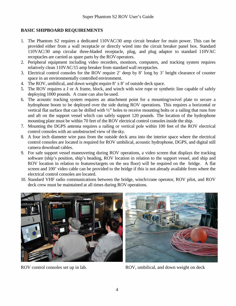
1. The Phantom S2 requires a dedicated 110VAC/30 amp circuit breaker for main power. This can be provided either from a wall receptacle or directly wired into the circuit breaker panel box. Standard 110VAC/30 amp circular three-bladed receptacle, plug, and plug adaptor to standard 110VAC receptacles are carried as spare parts by the ROV operators.
2. Peripheral equipment including video recorders, monitors, computers, and tracking system requires relatively clean 110VAC/15 amp breaker from standard wall receptacles.
3. Electrical control consoles for the ROV require 2’ deep by 8’ long by 3’ height clearance of counter space in an environmentally controlled environment.
4. The ROV, umbilical, and down weight require 8’ x 8’ of outside deck space. 5. The ROV requires a J or A frame, block, and winch with wire rope or synthetic line capable of safely
deploying 1000 pounds. A crane can also be used. 6. The acoustic tracking system requires an attachment point for a mounting/swivel plate to secure a
hydrophone boom to be deployed over the side during ROV operations. This requires a horizontal or vertical flat surface that can be drilled with ½” holes to receive mounting bolts or a railing that runs fore and aft on the support vessel which can safely support 120 pounds. The location of the hydrophone mounting plate must be within 70 feet of the ROV electrical control consoles inside the ship.
7. Mounting the DGPS antenna requires a railing or vertical pole within 100 feet of the ROV electrical control consoles with an unobstructed view of the sky.
8. A four inch diameter wire pass from the outside deck area into the interior space where the electrical control consoles are located is required for ROV umbilical, acoustic hydrophone, DGPS, and digital still camera download cables.
9. For safe support vessel maneuvering during ROV operations, a video screen that displays the tracking software (ship’s position, ship’s heading, ROV location in relation to the support vessel, and ship and ROV location in relation to features/targets on the sea floor) will be required on the bridge. A flat screen and 100’ video cable can be provided to the bridge if this is not already available from where the electrical control consoles are located.
10. Standard VHF radio communications between the bridge, winch/crane operator, ROV pilot, and ROV deck crew must be maintained at all times during ROV operations.
ROV control consoles set up in lab. ROV, umbilical, and down weight on deck
Super Phantom S2 ROV User’s Guide
5
CAMERAS AND LIGHTS Color Video – A Sony high resolution, single-chip color camera with auto iris, 12:1 zoom, and auto/manual focus provides video documentation during ROV operations. The video signal is routed from the ROV console to the On-Screen Display (OSD) video overlay device to a Toshiba DVD recorder (one hour record time on highest resolution), then to an AJA KiPRO digital video recorder, and finally to a Samsung 21” flat screen, LED color monitor. This ensures that if you are seeing the video and overlay information on the monitor that it is being correctly routed through the video recording equipment. This does not ensure that the video recording equipment is recording. The OSD provides a title page with information such as mission number, P.I. name, support vessel name, general location, ROV Dive number, KiPRO cut number, DVD disk number, and any other pertinent information that the scientist requires. This information is recorded as a header at the beginning of each digital recording and DVD disk. The OSD also provides data overlay on the video including time, date, ROV heading ribbon, ROV numeric heading in degrees, ROV depth in meters, ROV altitude above the sea floor in meters, and ROV umbilical cable turns counter for the pilot. All video documentation can be geo-referenced to ROV position by matching the time and date on the video to the navigation files (Excel spreadsheet) provided to the scientists by the ROV operations staff. An omni-directional microphone is available for audio annotation onto the recording media by the scientists. The Sony NTSC video format specifications are:
• Image Sensor 1/3” IT CCD • Pixels/effective pixels 410 x 380 • Picture Elements 768 (H) x 484 (V) • Horizontal Resolution (Center) >460 TV Lines • Vertical Resolution (Center) >350 TV Lines • Lens 12X zoom, auto focus, f1.8 to f2.7 • Diagonal Angle of view in air Wide angle: 117º, Tele: 10º • Diagonal Angle of view in water Wide angle: 79º, Tele: 7.4º • Minimum Illumination 2 LUX (F1.8) • Signal to Noise Ratio >48 dB • White Balance TTL Auto tracking
Digital Still Photographs – Geo-referenced digital still pictures are acquired with an Insite-Tritech Scorpio Plus digital still color TV camera and strobe. The camera provides "Through the lens" color video to the ROV video monitor that not only allows the operator to accurately frame still images, but it also can be used for video documentation. Note that only one camera (either the color video camera or the digital still camera) on the ROV can be monitored at one time. Switching between these two cameras is done at the ROV control console by the ROV pilot at the request of the scientific observer. This camera features a 4X zoom lens and corrected optics that virtually eliminates geometric and chromatic distortion. The internal electronics and imaging device are basically a Nikon Coolpix 995 digital still camera which is controlled by a laptop PC via RS-485 communications using a shielded- twisted pair of wires in the ROV umbilical cable. In fine resolution setting, the 1 gigabyte, onboard compact flash card can store 664 images in JPG format (approximately 1.0 Mb each), which are provided to the scientist on CD or DVD media. Images are downloaded from the camera at the end of each day via a USB/Ethernet cable into the laptop, and are stored in two locations at all times. The strobe unit, also built by Insite-Tritech, is a 76 Watt Seconds flash that is TTL auto controlled by the
Super Phantom S2 ROV User’s Guide
6
camera. The strobe unit is powered by four rechargeable AA batteries, which allows the strobe to be fired approximately 300 times per ROV dive. A running tally of the number of images taken during each dive is monitored, and the batteries will be replaced between dives if there is any possibility that the next dive will require additional strobe power. The digital still camera can be mounted either on the tilt platform or in a vertical configuration (straight down) on the crash frame. Additional digital still camera specifications include:
• Image Sensor 1 1/8” High density CCD • Image Size 3.34 megapixel ultrahigh definition (2048 x 1536 pixel) • Lens 4X Zoom-Nikkor, f8, 32 mm • Angle of View (4:3 format) Horizontal: Wide angle = 46°, Telephoto = 11.6°
Vertical: Wide angle = 34°, Telephoto = 8.7° • Focus Range 30 cm to ∞
Monochrome Low Light Camera – A Simrad Osprey OE1323 Silicon Intensifier Target (SIT) black and white video camera can be put on the ROV in place of the Scorpio Plus digital still camera and strobe. As with the Scorpio Plus, only one camera (either the color video camera or the low light SIT camera) on the ROV can be monitored at one time. Switching between these two cameras is done at the ROV control console by the ROV pilot at the request of the scientific observer. An example of the capability of this camera was noted in extremely clear water off Bermuda where excellent video images out to 50 meters were acquired in ambient light at 700 feet sea water. It is important to note that this is a low-light camera, and not a no-light camera. In other words, it does not provide an image at night (even with the moon at full) without artificial illumination. Red lenses can be fitted over the ROV lights for behavioral studies of fish species since the monochrome camera “sees” this as white light. The red lasers used as a scaling device on the ROV are also seen as two intense white dots. Camera specifications include:
• Image Sensor Silicon Intensifier Target RCA 4804/H/P2 • Horizontal Resolution (Center) 600 TV Lines • Lens Comutar V615, f1.5, 5.5mm • Focus Fixed 150 mm (6”) to ∞ • Diagonal Angle of view in water 110º • Minimum Illumination 5 x 10⁻⁴ LUX (tube faceplate) • Signal to Noise Ratio 34 dB (with CCIR pass filter) • Grey Scale Resolution 10 shades
Dual Red Laser Scaling Device – The two lasers used for scaling objects underwater were made by Harbor Branch Oceanographic Institution. They are mounted in a precision machined aluminum block to maintain the lasers in a parallel orientation at exactly 10 cm. The output power is 8.6 mW. The lasers are mounted on the ROV tilt platform directly under the video camera and are usually in the video and digital still frame unless the ROV is very close to the object or the cameras are zoomed in. The laser scaling device can be moved to the digital still camera when it is mounted in the vertical position on the ROV. This provides accurate scaling over the entire image in either axis.
Lights – Two 250-watt tungsten-halogen lights made by Deep Sea Power and Light are mounted on top of the ROV tilt platform and provide illumination for the color video camera. The light output can be
Super Phantom S2 ROV User’s Guide
7
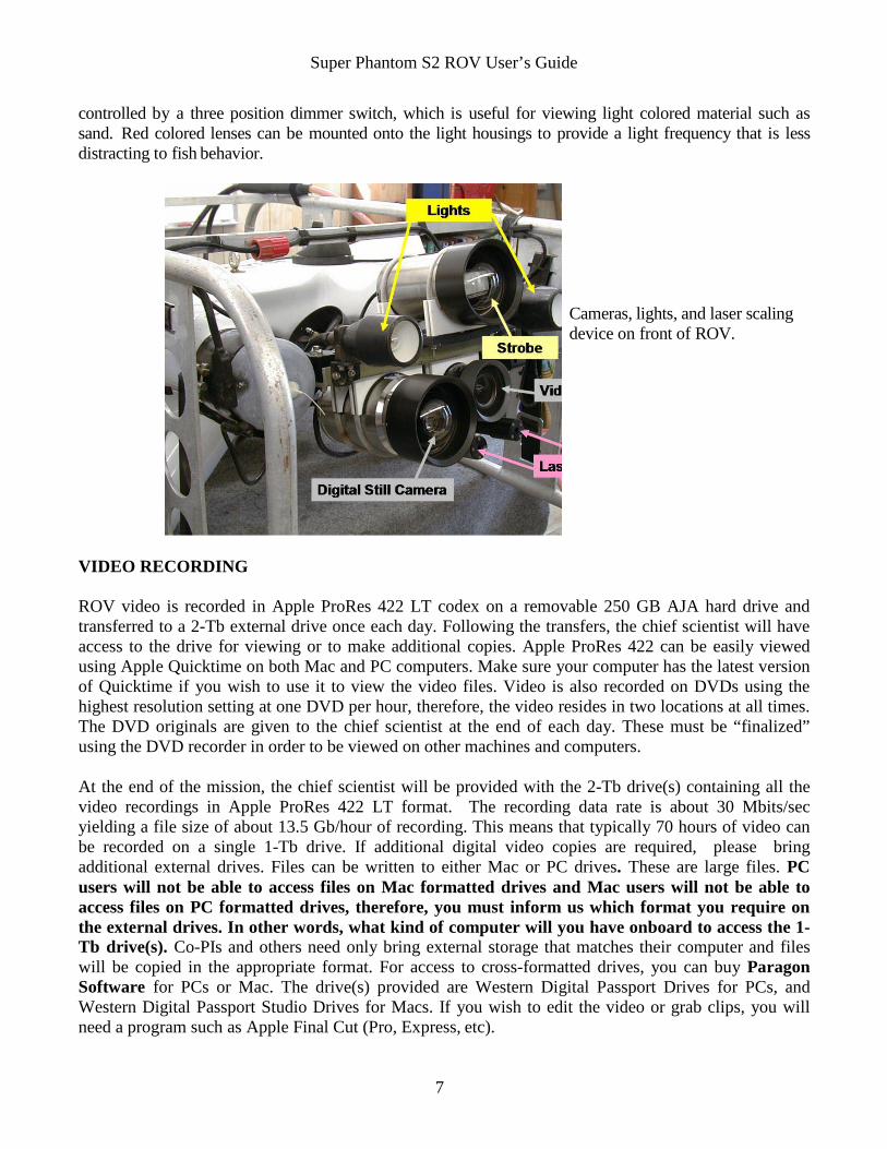
controlled by a three position dimmer switch, which is useful for viewing light colored material such as sand. Red colored lenses can be mounted onto the light housings to provide a light frequency that is less distracting to fish behavior.
Cameras, lights, and laser scaling device on front of ROV.
VIDEO RECORDING
ROV video is recorded in Apple ProRes 422 LT codex on a removable 250 GB AJA hard drive and transferred to a 2-Tb external drive once each day. Following the transfers, the chief scientist will have access to the drive for viewing or to make additional copies. Apple ProRes 422 can be easily viewed using Apple Quicktime on both Mac and PC computers. Make sure your computer has the latest version of Quicktime if you wish to use it to view the video files. Video is also recorded on DVDs using the highest resolution setting at one DVD per hour, therefore, the video resides in two locations at all times. The DVD originals are given to the chief scientist at the end of each day. These must be “finalized” using the DVD recorder in order to be viewed on other machines and computers.
At the end of the mission, the chief scientist will be provided with the 2-Tb drive(s) containing all the video recordings in Apple ProRes 422 LT format. The recording data rate is about 30 Mbits/sec yielding a file size of about 13.5 Gb/hour of recording. This means that typically 70 hours of video can be recorded on a single 1-Tb drive. If additional digital video copies are required, please bring additional external drives. Files can be written to either Mac or PC drives. These are large files. PC users will not be able to access files on Mac formatted drives and Mac users will not be able to access files on PC formatted drives, therefore, you must inform us which format you require on the external drives. In other words, what kind of computer will you have onboard to access the 1- Tb drive(s). Co-PIs and others need only bring external storage that matches their computer and files will be copied in the appropriate format. For access to cross-formatted drives, you can buy Paragon Software for PCs or Mac. The drive(s) provided are Western Digital Passport Drives for PCs, and Western Digital Passport Studio Drives for Macs. If you wish to edit the video or grab clips, you will need a program such as Apple Final Cut (Pro, Express, etc).
Super Phantom S2 ROV User’s Guide
8
NAVIGATION AND TRACKING The ROV uses an integrated navigation system consisting of Hypack 2017 software on a Dell computer, ORE Offshore 4410C Trackpoint II Underwater Acoustic Tracking System with an ORE Offshore 4377A transponder with depth telemetry, Furuno GP32 GPS, and Azimuth 1000 digital compass. This system provides real time tracking of the ROV and ship to the ROV operator and the support vessel’s bridge for navigation. ROV personnel install a Furuno GPS antenna and an ORE hydrophone on the vessel and survey their positions with respect to a reference point at the center of the vessel. The hydrophone mounting alignment is checked at the dock using submerged transponders. GPS antenna and hydrophone offsets, as well as ship dimensions, are entered into the Trackpoint II. The Trackpoint II interrogates the ORE 4377A-SL transponder on the ROV. Using the ORE three- element hydrophone, Trackpoint II determines slant range, bearing, and depth. The real-time Hypack navigation screen accurately displays the ship (to scale) with proper position and heading, and the position of the ROV. Hypack can also export ROV data in real time as a NMEA data string which contains ROV position only. Ship and ROV positions, in addition to the ROV depth, heading and altimeter reading, are logged and processed for each dive and provided to the scientist in an Excel file. Geo-referenced .tif files obtained with multibeam or side scan sonar can be entered into Hypack as background files to display target sites and features of interest to aid in ROV and support vessel navigation. The Trackpoint II acoustic tracking system can track up to 6 targets at one time, and additional Benthos UAT-376 transponders (transmit 25 or 27 kHz) and Helle pingers (27 kHz) are available to relocate instrumentation packages deployed in the ocean.
ORE Offshore 4410C Trackpoint II acoustic tracking system specifications are: • Horizontal Pinger Position Accuracy ± 0.75% RMS of Slant Range (depression angle > 45º
from horizontal) • Horizontal Transponder Position Accuracy Absolute Accuracy: ± 0.5% RMS of Slant Range
Repeatability Accuracy: ± 0.5% RMS of Slant Range • Slant Range Accuracy ± 1 meter (assuming correct speed of sound input) • Slant Range Resolution 0.3 meters • Receive Signal Frequency 22-30 kHz in 500 Hz increments • Receive Signal Pulse Duration 1.33 ms minimum • Receive Signal/Noise Ratio >40 dB at wideband filter • Transmitter Output Frequency 4.5-30 kHz in 500 Hz increments • Transmitter Output Pulse Width 1 to 15 ms in 0.1 ms increments • Transmitter Output Repetition Rate 1 to 20 seconds • Transmitter Output Power 100 or 500 watts into 300Ω, user selectable
ORE Offshore 4377A transponder specifications are: • Receive Frequency 19 kHz • Receive Pulse Width 5 ms minimum • Transmit Frequency for Navigation 24 kHz • Transmit Frequency for Depth Telemetry 23 kHz • Transponder Turn Around Time 15 ms • Transponder Lock-Out Time 1.9 seconds (Minimum interagation rate is 2 sec.) • Transponder Depth Rating 1000 meters
Super Phantom S2 ROV User’s Guide
9
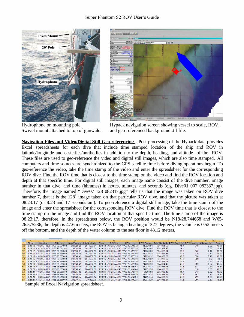
Hydrophone on mounting pole. Swivel mount attached to top of gunwale.
Hypack navigation screen showing vessel to scale, ROV, and geo-referenced background .tif file.
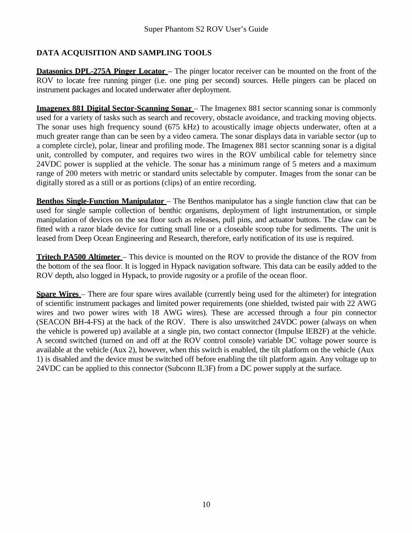
Navigation Files and Video/Digital Still Geo-referencing - Post processing of the Hypack data provides Excel spreadsheets for each dive that include time stamped location of the ship and ROV in latitude/longitude and easterlies/northerlies in addition to the depth, heading, and altitude of the ROV. These files are used to geo-reference the video and digital still images, which are also time stamped. All computers and time sources are synchronized to the GPS satellite time before diving operations begin. To geo-reference the video, take the time stamp of the video and enter the spreadsheet for the corresponding ROV dive. Find the ROV time that is closest to the time stamp on the video and find the ROV location and depth at that specific time. For digital still images, each image name consist of the dive number, image number in that dive, and time (hhmmss) in hours, minutes, and seconds (e.g. Dive01 007 082337.jpg). Therefore, the image named “Dive07 128 082317.jpg” tells us that the image was taken on ROV dive number 7, that it is the 128th image taken on that particular ROV dive, and that the picture was taken at 08:23:17 (or 8:23 and 17 seconds am). To geo-reference a digital still image, take the time stamp of the image and enter the spreadsheet for the corresponding ROV dive. Find the ROV time that is closest to the time stamp on the image and find the ROV location at that specific time. The time stamp of the image is 08:23:17, therefore, in the spreadsheet below, the ROV position would be N18-28.744668 and W65- 26.575236, the depth is 47.6 meters, the ROV is facing a heading of 327 degrees, the vehicle is 0.52 meters off the bottom, and the depth of the water column to the sea floor is 48.12 meters.
Sample of Excel Navigation spreadsheet.
Super Phantom S2 ROV User’s Guide
10
DATA ACQUISITION AND SAMPLING TOOLS Datasonics DPL-275A Pinger Locator – The pinger locator receiver can be mounted on the front of the ROV to locate free running pinger (i.e. one ping per second) sources. Helle pingers can be placed on instrument packages and located underwater after deployment.
Imagenex 881 Digital Sector-Scanning Sonar – The Imagenex 881 sector scanning sonar is commonly used for a variety of tasks such as search and recovery, obstacle avoidance, and tracking moving objects. The sonar uses high frequency sound (675 kHz) to acoustically image objects underwater, often at a much greater range than can be seen by a video camera. The sonar displays data in variable sector (up to a complete circle), polar, linear and profiling mode. The Imagenex 881 sector scanning sonar is a digital unit, controlled by computer, and requires two wires in the ROV umbilical cable for telemetry since 24VDC power is supplied at the vehicle. The sonar has a minimum range of 5 meters and a maximum range of 200 meters with metric or standard units selectable by computer. Images from the sonar can be digitally stored as a still or as portions (clips) of an entire recording.
Benthos Single-Function Manipulator – The Benthos manipulator has a single function claw that can be used for single sample collection of benthic organisms, deployment of light instrumentation, or simple manipulation of devices on the sea floor such as releases, pull pins, and actuator buttons. The claw can be fitted with a razor blade device for cutting small line or a closeable scoop tube for sediments. The unit is leased from Deep Ocean Engineering and Research, therefore, early notification of its use is required.
Tritech PA500 Altimeter – This device is mounted on the ROV to provide the distance of the ROV from the bottom of the sea floor. It is logged in Hypack navigation software. This data can be easily added to the ROV depth, also logged in Hypack, to provide rugosity or a profile of the ocean floor.
Spare Wires – There are four spare wires available (currently being used for the altimeter) for integration of scientific instrument packages and limited power requirements (one shielded, twisted pair with 22 AWG wires and two power wires with 18 AWG wires). These are accessed through a four pin connector (SEACON BH-4-FS) at the back of the ROV. There is also unswitched 24VDC power (always on when the vehicle is powered up) available at a single pin, two contact connector (Impulse IEB2F) at the vehicle. A second switched (turned on and off at the ROV control console) variable DC voltage power source is available at the vehicle (Aux 2), however, when this switch is enabled, the tilt platform on the vehicle (Aux 1) is disabled and the device must be switched off before enabling the tilt platform again. Any voltage up to 24VDC can be applied to this connector (Subconn IL3F) from a DC power supply at the surface.
Super Phantom S2 ROV User’s Guide
11
TETHER MANAGEMENT AND PENETRATIONS Different operating modes and tether management techniques are used to ensure the best possibility of a successful ROV dive. Current strength, bottom type, and science objectives will require different techniques of tether management. Some of the most common and successful techniques of tether management are discussed below. The tether shall always be tended with communications set up between the tender, operator, support vessel’s bridge, and crane or winch operator. Penetrations into large, natural enclosures will be considered only after a thorough external visual inspection. As a rule, penetrations into wrecks or areas that limit maneuverability shall not be performed. No penetrations will be permitted during live-boat operations.
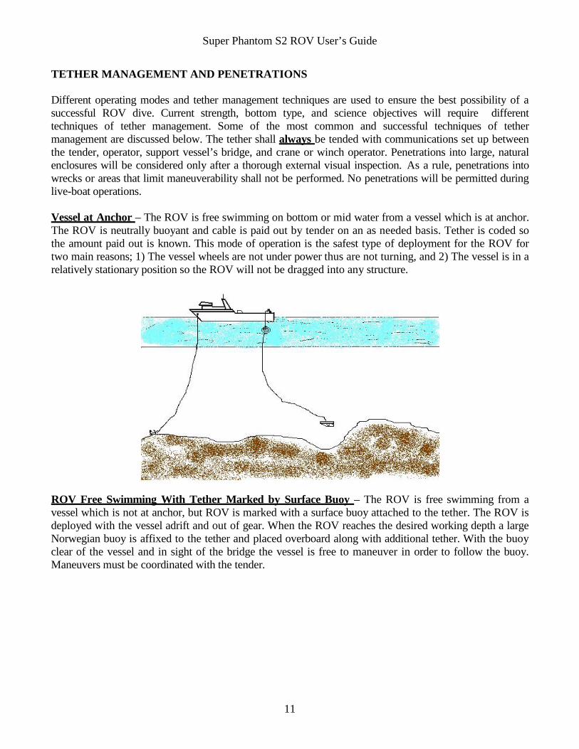
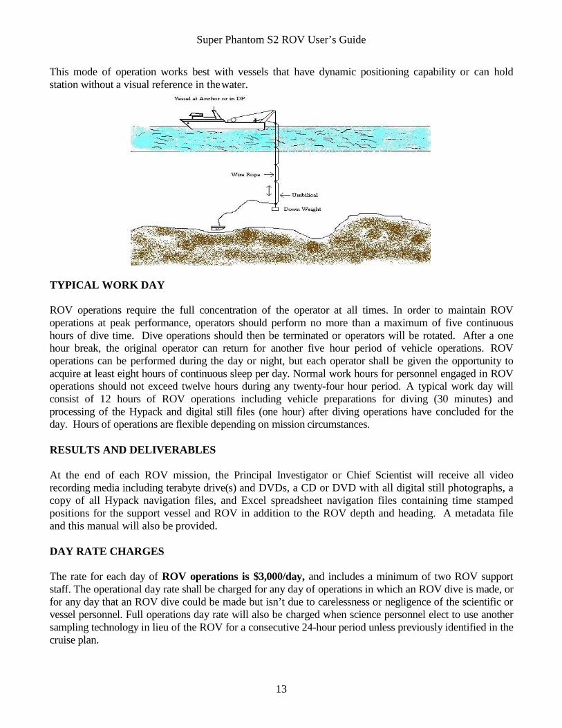
Vessel at Anchor – The ROV is free swimming on bottom or mid water from a vessel which is at anchor. The ROV is neutrally buoyant and cable is paid out by tender on an as needed basis. Tether is coded so the amount paid out is known. This mode of operation is the safest type of deployment for the ROV for two main reasons; 1) The vessel wheels are not under power thus are not turning, and 2) The vessel is in a relatively stationary position so the ROV will not be dragged into any structure.
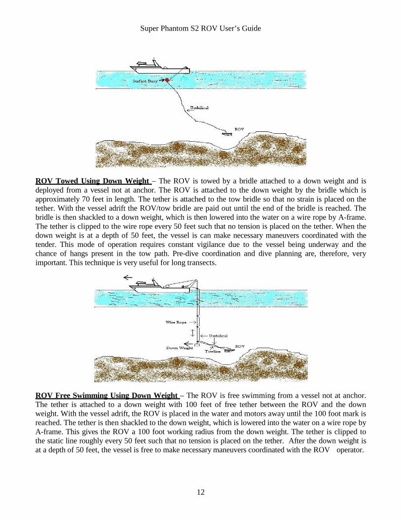
ROV Free Swimming With Tether Marked by Surface Buoy – The ROV is free swimming from a vessel which is not at anchor, but ROV is marked with a surface buoy attached to the tether. The ROV is deployed with the vessel adrift and out of gear. When the ROV reaches the desired working depth a large Norwegian buoy is affixed to the tether and placed overboard along with additional tether. With the buoy clear of the vessel and in sight of the bridge the vessel is free to maneuver in order to follow the buoy. Maneuvers must be coordinated with the tender.
Super Phantom S2 ROV User’s Guide
12
ROV Towed Using Down Weight – The ROV is towed by a bridle attached to a down weight and is deployed from a vessel not at anchor. The ROV is attached to the down weight by the bridle which is approximately 70 feet in length. The tether is attached to the tow bridle so that no strain is placed on the tether. With the vessel adrift the ROV/tow bridle are paid out until the end of the bridle is reached. The bridle is then shackled to a down weight, which is then lowered into the water on a wire rope by A-frame. The tether is clipped to the wire rope every 50 feet such that no tension is placed on the tether. When the down weight is at a depth of 50 feet, the vessel is can make necessary maneuvers coordinated with the tender. This mode of operation requires constant vigilance due to the vessel being underway and the chance of hangs present in the tow path. Pre-dive coordination and dive planning are, therefore, very important. This technique is very useful for long transects.
ROV Free Swimming Using Down Weight – The ROV is free swimming from a vessel not at anchor. The tether is attached to a down weight with 100 feet of free tether between the ROV and the down weight. With the vessel adrift, the ROV is placed in the water and motors away until the 100 foot mark is reached. The tether is then shackled to the down weight, which is lowered into the water on a wire rope by A-frame. This gives the ROV a 100 foot working radius from the down weight. The tether is clipped to the static line roughly every 50 feet such that no tension is placed on the tether. After the down weight is at a depth of 50 feet, the vessel is free to make necessary maneuvers coordinated with the ROV operator.
Super Phantom S2 ROV User’s Guide
13
This mode of operation works best with vessels that have dynamic positioning capability or can hold station without a visual reference in the water.
TYPICAL WORK DAY
ROV operations require the full concentration of the operator at all times. In order to maintain ROV operations at peak performance, operators should perform no more than a maximum of five continuous hours of dive time. Dive operations should then be terminated or operators will be rotated. After a one hour break, the original operator can return for another five hour period of vehicle operations. ROV operations can be performed during the day or night, but each operator shall be given the opportunity to acquire at least eight hours of continuous sleep per day. Normal work hours for personnel engaged in ROV operations should not exceed twelve hours during any twenty-four hour period. A typical work day will consist of 12 hours of ROV operations including vehicle preparations for diving (30 minutes) and processing of the Hypack and digital still files (one hour) after diving operations have concluded for the day. Hours of operations are flexible depending on mission circumstances.
RESULTS AND DELIVERABLES
At the end of each ROV mission, the Principal Investigator or Chief Scientist will receive all video recording media including terabyte drive(s) and DVDs, a CD or DVD with all digital still photographs, a copy of all Hypack navigation files, and Excel spreadsheet navigation files containing time stamped positions for the support vessel and ROV in addition to the ROV depth and heading. A metadata file and this manual will also be provided.
DAY RATE CHARGES
The rate for each day of ROV operations is $3,000/day, and includes a minimum of two ROV support staff. The operational day rate shall be charged for any day of operations in which an ROV dive is made, or for any day that an ROV dive could be made but isn’t due to carelessness or negligence of the scientific or vessel personnel. Full operations day rate will also be charged when science personnel elect to use another sampling technology in lieu of the ROV for a consecutive 24-hour period unless previously identified in the cruise plan.
Super Phantom S2 ROV User’s Guide
14
No day rate will be charged under the following circumstances: • ROV and associated equipment failure. • Any delay or suspension of ROV operations resulting from an error in judgment or negligence on the
part of the ROV support crew. A standby rate of $2,000/day will be charged for the following: • Each day of travel to/from port of embarkation/debarkation. For planning purposes, budget one travel
day for every 600 miles of distance between Wilmington, NC and ports of embarkation/debarkation. • Each day the ROV staff and asset is on location (in port) or aboard the vessel (in port, in transit or on
station) and dive operations do not take place. The following will be billed on an individual basis: • All travel involved with the mission will be charged at cost. • Excess shipping charges, when they occur, will be charged at cost. • Additional support personnel beyond two staff members that may be requested by the chief scientist
(e.g., additional staff members may be requested to increase the hours of operation, or contracting staff members with specialized skills to augment novel sampling equipment).