sunny boy 3000tl / 3600tl / 4000tl / 5000tl - sb3-5tl-21...
TRANSCRIPT

Front Cover
Operating ManualSUNNY BOY 3000TL / 3600TL / 4000TL / 5000TL
SB3-5TL-21-BE-en-10 | IMEN-SBXTL-21 | Version 1.0 AMERICAN ENGLISH

Legal Provisions SMA Solar Technology AG
2 SB3-5TL-21-BE-en-10 Operating Manual
Legal ProvisionsThe information contained in these documents is property of SMA Solar Technology AG. Any publication, whether in whole or in part, requires prior written approval by SMA Solar Technology AG. Internal reproduction used solely for the purpose of product evaluation or other proper use is allowed and does not require prior approval.
SMA WarrantyYou can download the current warranty conditions from the Internet at www.SMA-Solar.com.
TrademarksAll trademarks are recognized, even if not explicitly identified as such. A lack of identification does not mean that a product or symbol is not trademarked.
The Bluetooth word mark and logos are registered trademarks owned by Bluetooth SIG, Inc. and any use of these marks by SMA Solar Technology AG is under license.
QR Code is a registered trademark of DENSO WAVE INCORPORATED.
SMA Solar Technology AGSonnenallee 134266 Niestetal
GermanyTel. +49 561 9522-0Fax +49 561 9522-100
www.SMA.deE-Mail: [email protected] 2004 to 2013 SMA Solar Technology AG. All rights reserved.

SMA Solar Technology AG Table of Contents
Operating Manual SB3-5TL-21-BE-en-10 3
Table of Contents
1 Information on this Document .....................................................7
2 Safety.............................................................................................9
2.1 Intended Use............................................................................... 9
2.2 Skills of Qualified Persons.......................................................... 9
2.3 Safety Precautions.....................................................................10
3 Scope of Delivery .......................................................................12
4 Product Description.....................................................................13
4.1 Sunny Boy .................................................................................13
4.2 Interfaces and Functions...........................................................16
5 Mounting .....................................................................................18
5.1 Requirements for Mounting......................................................18
5.2 Mounting the Inverter ...............................................................22
6 Electrical Connection...................................................................23
6.1 Safety during Electrical Connection.........................................23
6.2 Overview of the Connection Area...........................................246.2.1 View from Below.............................................................................24
6.2.2 Interior View....................................................................................25
6.3 AC Connection..........................................................................266.3.1 Requirements for the AC Connection.............................................26
6.3.2 Connecting the Inverter to the Utility Grid.....................................27
6.3.3 Connecting Additional Grounding ................................................29
6.4 DC Connection .........................................................................306.4.1 Requirements for the DC Connection.............................................30
6.4.2 Connecting the PV Array................................................................31

Table of Contents SMA Solar Technology AG
4 SB3-5TL-21-BE-en-10 Operating Manual
7 Initial Start-Up .............................................................................33
7.1 Procedure..................................................................................33
7.2 Configuring the Country Data Set...........................................33
7.3 Setting the NetID......................................................................34
7.4 Commissioning the Inverter for the First Time..........................36
7.5 Self-Test in Accordance with CEI 0-21 for PV systems ≤ 6kW ....................................................................................37
7.5.1 Starting the Self-Test........................................................................37
7.5.2 Restarting the Self-Test ....................................................................39
8 Configuration ..............................................................................40
8.1 Procedure..................................................................................40
8.2 Changing the Display Language.............................................41
8.3 Changing Operating Parameters.............................................42
8.4 Deactivating Grounding Conductor Monitoring.....................42
8.5 Activating and Setting SMA OptiTrac Global Peak...............43
9 Operation....................................................................................44
9.1 Display Overview.....................................................................44
9.2 Activating and Operating the Display.....................................46
9.3 Calling Up Display Messages of the Start Phase...................46
10 Disconnecting the Inverter from Voltage Sources....................47
11 Recommissioning the Inverter....................................................49
12 Decommissioning the Inverter ...................................................51

Operating Manual SB3-5TL-21-BE-en-10 5
SMA Solar Technology AG Table of Contents
13 Technical Data.............................................................................53
13.1 DC/ AC......................................................................................5313.1.1 Sunny Boy 3000TL / 3600TL........................................................53
13.1.2 Sunny Boy 4000TL / 5000TL........................................................55
13.2 General Data............................................................................56
13.3 Protective Devices.....................................................................57
13.4 Climatic Conditions...................................................................58
13.5 Equipment..................................................................................58
13.6 Torques......................................................................................59
13.7 Electronic Solar Switch.............................................................59
13.8 Data Storage Capacity ............................................................59
14 Accessories..................................................................................60
15 Contact.........................................................................................61

6 SB3-5TL-21-BE-en-10 Operating Manual
Table of Contents SMA Solar Technology AG

Operating Manual SB3-5TL-21-BE-en-10 7
SMA Solar Technology AG 1 Information on this Document
1 Information on this Document
Validity
This document is valid for the following device types from firmware version 2.55:
• SB 3000TL-21 (Sunny Boy 3000TL)
• SB 3600TL-21 (Sunny Boy 3600TL)
• SB 4000TL-21 (Sunny Boy 4000TL)
• SB 5000TL-21 (Sunny Boy 5000TL)
Target Group
This document is intended for qualified persons and end users. Some of the tasks described in this document may only be performed by persons with the appropriate qualifications (see Section 2.2 "Skills of Qualified Persons", page 9). Such tasks are marked with a warning symbol and the caption "Qualified person". Tasks that do not require any particular qualification are not marked and can also be performed by end users.STSatz_Hinw_Weiterführende Informationen
Additional Information
Links to additional information can be found at www.SMA-Solar.com:
Document title Document type
SUNNY BOY 3000TL / 3600TL / 4000TL / 5000TL Service Manual
Application for SMA Grid Guard Code Certificate
Leading Leakage Currents Technical Information
Circuit Breaker Technical Information
Module Technology Technical Information
Efficiency and Derating Technical Description
SMA Bluetooth ‒ SMA Bluetooth Wireless Technology in Practice Technical Information
SMA Bluetooth Wireless Technology Technical Description
Firmware Update with SD Card Technical Description
Shade Management Technical Information
Temperature Derating Technical Information
Criteria for Selecting a Residual-Current Device Technical Information
Webconnect Systems in Sunny Portal User Manual
Parameter List Technical Information
Overview of Rotary Switch Positions Technical Information

8 SB3-5TL-21-BE-en-10 Operating Manual
1 Information on this Document SMA Solar Technology AG
Symbols
Nomenclature
Symbol Explanation
Indicates a hazardous situation which, if not avoided, will result in death or serious injury
Indicates a hazardous situation which, if not avoided, can result in death or serious injury
Indicates a hazardous situation which, if not avoided, can result in minor or moderate injury
Indicates a situation which, if not avoided, can result in property damage
Sections describing tasks to be performed by qualified personnel only
Information that is important for a specific topic or goal, but is not safety-relevant
Indicates a requirement for meeting a specific goal
Desired result
A problem that could occur
Complete designation Designation in this document
Electronic Solar Switch ESS
PV system System
SMA Bluetooth Wireless Technology Bluetooth
Sunny Boy Inverter, product

Operating Manual SB3-5TL-21-BE-en-10 9
SMA Solar Technology AG 2 Safety
2 Safety
2.1 Intended UseThe Sunny Boy is a transformerless PV inverter with two MPP trackers which converts the direct current of the PV array to grid-compliant alternating current and feeds it into the utility grid.STSatz_Best Verwend_OutdoorThe product is suitable for indoor and outdoor use.Protection class II in accordance with IEC 61703The product must only be operated with PV arrays of protection class II, in accordance with IEC 61730, application class A. The PV modules must be suitable for use with this product.
PV modules with a high capacity to ground must only be used if their coupling capacity does not exceed 1.4 F (for information on how to calculate the coupling capacity, see Technical Information "Leading Leakage Currents" at www.SMA-Solar.com). Observe the permitted operating range of all componentsAll components must remain within their permitted operating ranges at all times. Länderzulassung und FreigabeThe product must only be used in countries for which it is approved or released by SMA Solar Technology AG and the grid operator. STSatz_Best Verwend_Produkt ändernUse this product only in accordance with the enclosed documentation and with the local standards and directives. Any other application may cause injury to persons or lead to property damage.
For safety reasons, it is forbidden to modify the product or install components that are not explicitly recommended or distributed by SMA Solar Technology AG for this product. Unauthorized modifications and installations will void all warranty claims.
Any use of the product other than that described in the Intended Use section does not qualify as appropriate.
The enclosed documentation is an integral part of this product. Keep the documentation in a convenient place for future reference and observe the instructions.The type label must be permanently attached to the product.
2.2 Skills of Qualified PersonsOnly qualified persons are allowed to perform the tasks marked in this document with a warning symbol and the caption "Qualified person". Qualified persons must have the following skills:
• Knowledge of how an inverter works and is operated
• Training in how to deal with the dangers and risks associated with installing and using electrical devices and plants
• Training in the installation and commissioning of electrical devices and plants
• Knowledge of the applicable standards and directives
• Knowledge of and adherence to this document and all safety precautions

10 SB3-5TL-21-BE-en-10 Operating Manual
2 Safety SMA Solar Technology AG
2.3 Safety PrecautionsSTSatz_Sicherh_EinleitungssatzThis section contains safety precautions that must be observed at all times when working on or with the product.
To prevent personal injury or property damage and to ensure long-term operation of the product, read this section carefully and follow all safety precautions at all times.
SiHiw_Stromschlag durch hohe Spannung
SiHiw_nicht geerdetes PV-Modul
Danger to life due to high voltages in the inverter The inverter should be mounted, installed and commissioned by qualified persons only. This also applies to troubleshooting.
• Always operate the inverter in a closed state.
• Do not touch exposed cable ends.
• Have the inverter mounted, installed and commissioned by qualified persons only.
• If an error occurs, have it rectified by qualified persons.
Danger to life due to high voltagesWhen exposed to sunlight, the PV array generates dangerous DC voltage which is present in the DC conductors and the live components of the inverter. Touching the DC conductors or the live components can lead to lethal electric shocks.
• Do not touch the DC conductors.
• Do not touch any live components of the inverter.
• Prior to performing any work on the inverter, disconnect it from all voltage sources, as described in this document (see Section 10, page 47).
Danger to life due to electric shockTouching an ungrounded PV module or an array frame can cause a fatal electric shock.
• Connect and ground the PV modules, array frame and electrically conductive surfaces so that there is continuous conduction. Observe the applicable local regulations.
Risk of burns due to hot enclosure parts Some parts of the enclosure can get hot during operation.
• Do not touch any parts other than the lower enclosure lid of the inverter during operation.

Operating Manual SB3-5TL-21-BE-en-10 11
SMA Solar Technology AG 2 Safety
SiHiw_Vor Berühren erden
Damage to the seal of the enclosure lid during sub-zero conditionsIf you open the upper and lower enclosure lid during sub-zero conditions, the seal of the enclosure can be damaged. As a result, moisture can penetrate the inverter.
• Do not open the inverter at ambient temperatures lower than -5C.
• If a layer of ice has formed on the seal of the lid in sub-zero conditions, remove it prior to opening the inverter (e.g. by melting the ice with warm air). Observe the applicable safety regulations.
Damage to the inverter due to electrostatic dischargeTouching electronic components can cause damage to or destroy the inverter through electrostatic discharge.
• Ground yourself before touching any components.
Damage to the display or the type label due to the use of cleaning agents• If the inverter is dirty, clean the enclosure, the cooling fins, the enclosure lid, the type label,
the display, and the LEDs using only water and a cloth.

12 SB3-5TL-21-BE-en-10 Operating Manual
3 Scope of Delivery SMA Solar Technology AG
3 Scope of DeliverySTSatz_Lieferumfang_Inhalt prüfenCheck the scope of delivery for completeness and any visible damage. Contact your distributor if the scope of delivery is incomplete or damaged.
Figure 1: Components included in the scope of delivery
Item Quantity Designation
A 1 Inverter*
* Optional without Electronic Solar Switch (ESS)
B 1 Wall mounting bracket
C 4 Positive DC connector
D 4 Negative DC connector
E 8 Sealing plug for DC connectors
F 1 Operating manual, supplementary sheet with default settings, installation manual of the DC connector
G 1 Warning label

Operating Manual SB3-5TL-21-BE-en-10 13
SMA Solar Technology AG 4 Product Description
4 Product Description
4.1 Sunny BoyThe Sunny Boy is a transformerless PV inverter with two MPP trackers which converts the direct current of the PV array to grid-compliant alternating current and feeds it into the utility grid.
Figure 2: Sunny Boy design
Item Explanation
A Type label
The type label uniquely identifies the inverter. The type label is located on the right-hand side of the enclosure. You will require the information on the type label to use the product safely and when seeking customer support from the SMA Service Line. You will find the following information on the type label:
• Device type (Model)
• Serial number (Serial No.)
• Date of manufacture
• Device-specific characteristics
B LEDs
The LEDs indicate the operating state of the inverter.
C Display
The display shows the current operating data and events or errors.

14 SB3-5TL-21-BE-en-10 Operating Manual
4 Product Description SMA Solar Technology AG
Symbols on the inverter, the type label and the ESS
D Electronic Solar Switch (ESS)*
The ESS and the DC connectors form a DC load-break switch. When plugged in, the ESS forms a conductive path between the PV array and the inverter. Removing the ESS interrupts the DC electric circuit and removing all DC connectors disconnects the PV array completely from the inverter.
E Lower enclosure lid
F Upper enclosure lid
* Optional
Symbol Explanation
Green LED: operating state of the inverter
Green LED is glowing: the inverter is in operation.
Green LED is flashing: the requirements for the connection to the utility grid have not been met.
Red LED: observe the documentation
Red LED is glowing: an error has occurred that must be rectified. Read the service manual at www.SMA-Solar.com.
Blue LED: active communication via Bluetooth
Danger
This symbol indicates that the inverter must be additionally grounded if additional grounding or equipotential bonding is required locally(see Section 6.3.3, page 29).
QR Code
Links to additional information on the inverter can be found at www.SMA-Solar.com.
Operating the inverter without the lower enclosure lid is prohibited. Always operate the inverter with the lower enclosure lid.
Item Explanation

Operating Manual SB3-5TL-21-BE-en-10 15
SMA Solar Technology AG 4 Product Description
Operating principle of the ESS:
• If the ESS is plugged in, the DC electric circuit is closed.
• To interrupt the DC electric circuit, you must perform the following steps in the order given:– Remove the ESS.
– Unlock and remove all DC connectors.
Danger to life due to high voltages
The product operates at high voltages. All work on the product must be carried out by qualified persons only.
Risk of burns from hot surfaces
The product can get hot during operation. Avoid contact during operation. Allow the product to cool down sufficiently before carrying out any work. Wear personal protective equipment such as safety gloves.
Observe the documentation
Observe all the documentation supplied with the product.
Direct current
The product does not have a transformer.
Alternating current
WEEE designation
Do not dispose of the product together with the household waste but in accordance with the locally applicable disposal regulations for electronic waste.
CE marking
The product complies with the requirements of the applicable EU directives.
Device class ID
The product is equipped with a wireless component and complies with device class 2.
Degree of protection IP65
The product is protected against dust intrusion and water jets from any angle.
Symbol Explanation

16 SB3-5TL-21-BE-en-10 Operating Manual
4 Product Description SMA Solar Technology AG
4.2 Interfaces and Functions
Bluetooth
The inverter can communicate via Bluetooth with various Bluetooth devices (information on supported SMA products at www.SMA-Solar.com).
RS485
The inverter can communicate with SMA communication products via the RS485 interface (information on supported SMA products at www.SMA-Solar.com). The RS485 interface can be retrofitted.
Speedwire/ Webconnect
Speedwire is a type of communication based on Ethernet allowing you to connect the inverter to a Speedwire network. Webconnect allows for data exchange between the inverter and Sunny Portal. Sunny Portal is an Internet portal which allows you to monitor PV systems and visualize and present PV system data. The Speedwire/ Webconnect data module can be retrofitted.
Multifunction relay
You can configure the multi-function relay for various operating modes. The multi-function relay is used, for example, to switch fault indicators on or off (for information on installation and configuration, see installation manual of the multi-function relay). The multi-function relay can be retrofitted.
The product is suitable for outdoor installation.
RAL quality mark for solar products
The product complies with the requirements of the German Institute for Quality Assurance and Certification.
Certified safety
The product is VDE-tested and complies with the requirements of the German Equipment and Product Safety Act.
C-Tick
The product complies with the requirements of the applicable Australian EMC standards.
Symbol Explanation

Operating Manual SB3-5TL-21-BE-en-10 17
SMA Solar Technology AG 4 Product Description
SMA Power Control Module
The SMA Power Control Module enables the inverter to implement grid management and is equipped with an additional multi-function relay (for information on installation and configuration, see the SMA Power Control Module installation manual). The SMA Power Control Module can be retrofitted.
Fan retrofit kit
The fan retrofit kit is used for additional inverter cooling at high ambient temperatures and also has a multi-function relay (for information on installation and configuration, see the fan retrofit kit installation manual). The fan retrofit kit can be retrofitted, and it cannot be operated in parallel with the SMA Power Control Module.
SMA OptiTrac Global Peak
SMA OptiTrac Global Peak is a further development of the SMA OptiTrac and allows the operating point of the inverter to follow the MPP precisely at all times. SMA OptiTrac Global Peak also means that the inverter can detect the presence of multiple maximum power points in the available operating range, such as can occur in partially shaded PV strings in particular.
Grid management services
The inverter is equipped with grid management functions.
Depending on the requirements of the grid operator, you can activate and configure the functions(e.g. active power limitation) via operating parameters.
All-pole sensitive residual-current monitoring unit
The all-pole sensitive residual-current monitoring unit detects alternating and direct differential currents. The integrated differential current sensor detects the current difference between the neutral conductor and the number of line conductors for single-phase and three-phase inverters. If the current difference increases suddenly, the inverter disconnects from the utility grid.

18 SB3-5TL-21-BE-en-10 Operating Manual
5 Mounting SMA Solar Technology AG
5 Mounting
5.1 Requirements for MountingRequirements for the mounting location:WaHiw_Lebensgefahr durch Feuer oder Explosion
The mounting location must be inaccessible to children.
A solid support surface must be available for mounting, e.g. concrete or masonry. When mounted on drywall or similar materials inside the home, the inverter will develop audible vibrations during operation which could be perceived as annoying.
The mounting location must be suitable for the weight and dimensions of the inverter (see Section 13 "Technical Data", page 53).
Climatic conditions must be met (see Section 13 "Technical Data", page 53).
The ambient temperature must be below 40C to ensure the optimal operation of the inverter.
The mounting location should be clear and safely accessible at all times without the need for any auxiliary equipment (such as scaffolding or lifting platforms). Non-fulfillment of these criteria may restrict servicing.
The mounting location should not be exposed to direct solar irradiation. Direct solar irradiation can cause the inverter to overheat. As a result, the inverter reduces its power output.
Danger to life due to fire or explosionDespite careful construction, electrical devices can cause fires.
• Do not mount the product in areas containing highly flammable materials.
• Do not mount the product in potentially explosive atmospheres.

Operating Manual SB3-5TL-21-BE-en-10 19
SMA Solar Technology AG 5 Mounting
Dimensions for Wall Mounting:
Figure 3: Wall mounting bracket dimensions

20 SB3-5TL-21-BE-en-10 Operating Manual
5 Mounting SMA Solar Technology AG
Recommended clearances:
Provided that the recommended clearances are observed, adequate heat dissipation will be ensured as well as sufficient space to remove the ESS if necessary. Sufficient heat dissipation prevents a reduction in inverter power as a result of high temperatures (details on temperature derating can be found in the Technical Information "Temperature Derating" at www.SMA-Solar.com).
Observe the recommended clearances to walls as well as to other inverters or objects.
If multiple inverters are mounted in areas with high ambient temperatures, increase the clearances between the inverters and ensure sufficient fresh-air supply.
Figure 4: Recommended clearances

Operating Manual SB3-5TL-21-BE-en-10 21
SMA Solar Technology AG 5 Mounting
Permitted and prohibited mounting positions
Mount the inverter in a permitted position. This will ensure that no moisture can penetrate the inverter.
The inverter should be mounted at eye level. This will ensure that display messages and LED signals can be read without difficulty.
Figure 5: Permitted and prohibited mounting positions
22 SB3-5TL-21-BE-en-10 Operating Manual
5 Mounting SMA Solar Technology AG
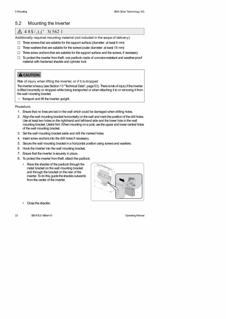
5.2 Mounting the Inverter
Additionally required mounting material (not included in the scope of delivery):
Three screws that are suitable for the support surface (diameter: at least 6 mm)
Three washers that are suitable for the screws (outer diameter: at least 18 mm)
Three screw anchors that are suitable for the support surface and the screws, if necessary
To protect the inverter from theft: one padlock made of corrosion-resistant and weather-proof material with hardened shackle and cylinder lock
Procedure:
1. Ensure that no lines are laid in the wall which could be damaged when drilling holes.
2. Align the wall mounting bracket horizontally on the wall and mark the position of the drill holes. Use at least two holes on the right-hand and left-hand side and the lower hole in the wall mounting bracket. Useful hint: When mounting on a post, use the upper and lower central holes of the wall mounting bracket.
3. Set the wall mounting bracket aside and drill the marked holes.
4. Insert screw anchors into the drill holes if necessary.
5. Secure the wall mounting bracket in a horizontal position using screws and washers.
6. Hook the inverter into the wall mounting bracket.
7. Ensure that the inverter is securely in place.
8. To protect the inverter from theft, attach the padlock:
• Close the shackle.
Risk of injury when lifting the inverter, or if it is droppedThe inverter is heavy (see Section 13 "Technical Data", page 53). There is risk of injury if the inverter is lifted incorrectly or dropped while being transported or when attaching it to or removing it from the wall mounting bracket.
• Transport and lift the inverter upright.
• Place the shackle of the padlock through the metal bracket on the wall mounting bracket and through the bracket on the rear of the inverter. To do this, guide the shackle outwards from the center of the inverter.
4 8 $ / ,) ,( ' 3( 562 1

Operating Manual SB3-5TL-21-BE-en-10 23
SMA Solar Technology AG 6 Electrical Connection
6 Electrical Connection
6.1 Safety during Electrical ConnectionSiHiw_Stromschlag durch hohe Spannung
SiHiw_Vor Berühren erden
Danger to life due to high voltagesWhen exposed to sunlight, the PV array generates dangerous DC voltage which is present in the DC conductors and the live components of the inverter. Touching the DC conductors or the live components can lead to lethal electric shocks.
• Do not touch the DC conductors.
• Do not touch any live components of the inverter.
• Prior to performing any work on the inverter, disconnect it from all voltage sources, as described in this document (see Section 10, page 47).
Damage to the seal of the enclosure lid during sub-zero conditionsIf you open the upper and lower enclosure lid during sub-zero conditions, the seal of the enclosure can be damaged. As a result, moisture can penetrate the inverter.
• Do not open the inverter at ambient temperatures lower than -5C.
• If a layer of ice has formed on the seal of the lid in sub-zero conditions, remove it prior to opening the inverter (e.g. by melting the ice with warm air). Observe the applicable safety regulations.
Damage to the inverter due to electrostatic dischargeTouching electronic components can cause damage to or destroy the inverter through electrostatic discharge.
• Ground yourself before touching any components.
24 SB3-5TL-21-BE-en-10 Operating Manual
6 Electrical Connection SMA Solar Technology AG
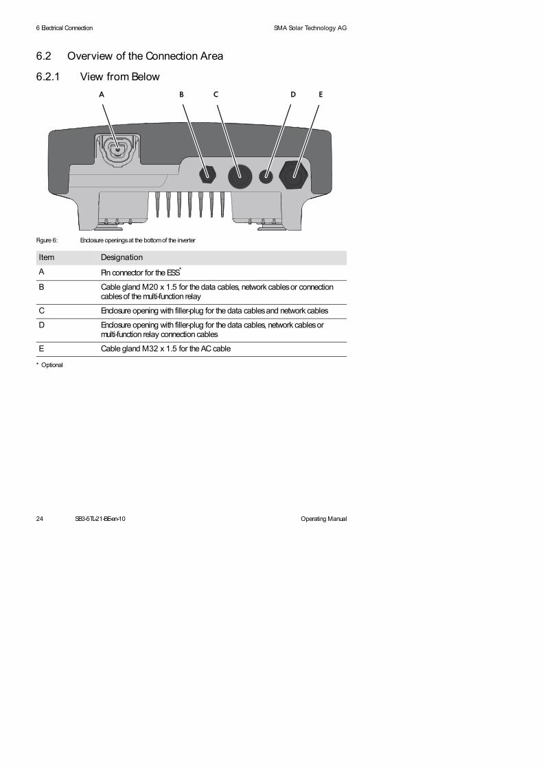
6.2 Overview of the Connection Area
6.2.1 View from Below
Figure 6: Enclosure openings at the bottom of the inverter
Item Designation
A Pin connector for the ESS*
* Optional
B Cable gland M20 x 1.5 for the data cables, network cables or connection cables of the multi-function relay
C Enclosure opening with filler-plug for the data cables and network cables
D Enclosure opening with filler-plug for the data cables, network cables or multi-function relay connection cables
E Cable gland M32 x 1.5 for the AC cable

Operating Manual SB3-5TL-21-BE-en-10 25
SMA Solar Technology AG 6 Electrical Connection
6.2.2 Interior View
Figure 7: Connection areas in the interior of the inverter
Item Designation
A 2 positive and 2 negative DC connectors, input A
B Pin connector for the ESS*
* Optional
C 2 positive and 2 negative DC connectors, input B
D Pin connector for connecting the multi-function relay or the SMA Power Control Module*
E Pin connector for connecting the communication interface for RS485 or Speedwire/ Webconnect*
F Connecting terminal plate for connecting the AC cable
G Switch for temporarily changing the display language to English (for service purposes)
H Rotary switch for configuring the NetID
I Rotary switch B for setting the display language
K Rotary switch A for setting the country data set
L Slot SD memory card
M Mounting location for the control module of the fan retrofit kit*
N Grounding terminal for additional grounding of the inverter

26 SB3-5TL-21-BE-en-10 Operating Manual
6 Electrical Connection SMA Solar Technology AG
6.3 AC Connection
6.3.1 Requirements for the AC ConnectionCable requirements:
External diameter: 12 mm to 21 mm
Wire size: max. 10 mm2
Insulation stripping length: 12 mm
The cable must be dimensioned in accordance with the local and national directives for the dimensioning of cables. The requirements for the minimum wire size derive from these directives. Examples of factors influencing cable dimensioning are: nominal AC current, type of cable, routing method, cable bundling, ambient temperature and maximum desired line losses (for calculation of line losses, see design software Sunny Design from software version 2.0 www.SMA-Solar.com).
Load-break switch and cable protection:WaHiw_Schraubsicherungen als Lasttrenneinrichtung
In PV systems with multiple inverters, protect each inverter with a separate circuit breaker. Make sure to observe the maximum permissible fuse protection (see Section 13 "Technical Data", page 53). This will prevent residual voltage being present at the corresponding cable after disconnection.
Loads installed between the inverter and the circuit breaker must be fused separately.
Overvoltage categoryOvervoltage category
The inverter can be deployed in grids of installation category III or lower, as defined under IEC 60664-1. This means that the inverter can be permanently connected at the grid-connection point in a building. In installations involving long outdoor cable routes, additional measures must be taken so that the overvoltage category is reduced from IV to III (see Technical Information "Overvoltage Protection" at www.SMA-Solar.com).Residual-current monitoring unit:
If an external residual-current device is required, install a residual-current device which trips at a residual current of 100 mA or higher (for details on selecting a residual-current device, see Technical Information "Criteria for Selecting a Residual-Current Device" at www.SMA-Solar.com).
Damage to the inverter due to the use of screw-type fuses as load-break switchesScrew-type fuses (e.g. DIAZED fuse or NEOZED fuse) are not load-break switches.
• Do not use screw-type fuses as load-break switches.
• Use a load-break switch or circuit breaker as a load disconnection unit (for information and design examples, see Technical Information "Circuit Breaker" at www.SMA-Solar.com).

Operating Manual SB3-5TL-21-BE-en-10 27
SMA Solar Technology AG 6 Electrical Connection
Grounding conductor monitoring:
The inverter is equipped with a grounding conductor monitoring device. This grounding conductor monitoring device detects when there is no grounding conductor connected and disconnects the inverter from the utility grid if this is the case. Depending on the installation site and grid configuration, it may be advisable to deactivate the grounding conductor monitoring. This is necessary, for example, in an IT network if no neutral conductor is present and you intend to install the inverter between two line conductors. If you are uncertain about this, contact your grid operator or SMA Solar Technology AG.
Grounding conductor monitoring must be deactivated after initial start-up depending on the grid configuration (see Section 8.4, page 42).
6.3.2 Connecting the Inverter to the Utility Grid
Requirements:
The connection requirements of the grid operator must be met.
The line voltage must be in the permissible range. The exact operating range of the inverter is specified in the operating parameters.
Procedure:
1. Disconnect the circuit breaker and secure against reconnection.
2. If an additional DC load-break switch is available, switch off the DC load-break switch and secure against re-connection.
3. If the ESS is in use and plugged in, remove the ESS.
4. Unscrew all six screws of the lower enclosure lid using an Allen key (AF 3) and remove the enclosure lid.
Safety according to IEC 62109 when the grounding conductor monitoring is deactivated
In order to guarantee safety according to IEC 62109 when the grounding conductor monitoring is deactivated, one of the following measures must be met:
• Connect a grounding conductor made of copper wire with a cross-section of at least 10 mm to the connecting terminal plate for the AC cable.
• Connect additional grounding with the same cross-section as the connected grounding conductor at the connecting terminal plate for the AC cable (see Section 6.3.3 "Connecting Additional Grounding", page 29). This prevents touch current if the grounding conductor at the connecting terminal plate for the AC cable fails.
Connection of additional grounding
In some countries an additional grounding is required. In each case, observe the locally applicable regulations.
4 8 $ / ,) ,( ' 3( 562 1

28 SB3-5TL-21-BE-en-10 Operating Manual
6 Electrical Connection SMA Solar Technology AG
5. Loosen the screw on the display and flip the display up to have more space to make the connection.
The display clicks into place.
6. Unscrew the swivel nut from the cable gland.
7. If the outer diameter of the cable is between 15 mm and 21 mm, remove the inner sealing ring from the cable gland.
8. Move the swivel nut of the cable gland over the AC cable and then route the AC cable through the cable gland into the inverter.
9. Dismantle the AC cable.
10. Shorten L and N by 5 mm each.
11. Strip 18 mm of the L, N and PE insulation each.
14. Ensure that all conductors are securely in place.
15. Screw the swivel nut onto the cable gland.
16. If the display is raised, lower it and tighten the screw.
12. Push the safety levers of the connecting terminal plate for the AC cable right up to the stop.
13.
Danger of crushing when safety levers snap shutThe safety levers close by snapping down fast and hard.
• Connect PE, N and L according to the labeling to the connecting terminal plate for the AC cable and push the safety levers down with your thumb only. Do not grip the entire connecting terminal plate for the AC cable between finger and thumb and keep fingers out from under the safety levers.

Operating Manual SB3-5TL-21-BE-en-10 29
SMA Solar Technology AG 6 Electrical Connection
6.3.3 Connecting Additional Grounding
If additional grounding or equipotential bonding is required locally, you can connect additional grounding to the inverter. This prevents touch current if the grounding conductor at the connecting terminal plate for the AC cable fails.
Cable requirement:
Grounding cable cross-section: 10 mm at maximum
Procedure:
1. Strip the grounding cable insulation.
3. Feed the grounding cable under the clamping bracket. Position the grounding conductor on the left-hand side.
4. Tighten the clamping bracket with the screw and conical spring washer (torque: 6 Nm). The teeth of the conical spring washer must face the clamping bracket.
2. Loosen the screw using an Allen key (AF4), until the grounding cable can be led under the clamping bracket.
4 8 $ / ,) ,( ' 3( 562 1

30 SB3-5TL-21-BE-en-10 Operating Manual
6 Electrical Connection SMA Solar Technology AG
6.4 DC Connection
6.4.1 Requirements for the DC ConnectionFunkt.Titel_Anforderungen an die PV-Module pro EingangRequirements for the PV modules per input:
All PV modules must be of the same type.
The same number of series-connected PV modules must be connected to all strings.
All PV modules must be aligned identically.
All PV modules must have the same tilt angle.
The maximum input current per string must be maintained and must not exceed the through-fault current of the DC connectors (see Section 13 "Technical Data", page 53).
The limiting values for the input voltage and the input current of the inverter must be adhered to (see Section 13 "Technical Data", page 53).
On the coldest day based on statistical records, the open-circuit voltage of the PV array must never exceed the maximum input voltage of the inverter.
The positive connection cables of the PV modules must be fitted with the positive DC connectors (for information on assembling DC connectors, see the DC connector installation manual).
The negative connection cables of the PV modules must be fitted with the negative DC connectors (for information on assembling DC connectors, see the DC connector installation manual).
Mixed connection
Use of Y adapters for parallel connection of strings
The Y adapters must not be used to interrupt the DC electric circuit.
• Do not use the Y adapters in the immediate vicinity of the inverter. The adapters must not be visible or freely accessible.
• In order to interrupt the DC electric circuit, always disconnect the inverter as described in this document (see Section 10, page 47).
In case of incorrect connection of the DC cables, the requirements of the EMC directive are no longer met.
If the positive pole and the negative pole of a string are not connected to the same input, the inverter no longer meets the requirements of the EMC directive.
• Always connect the positive pole and the negative pole of one string to the same input.

Operating Manual SB3-5TL-21-BE-en-10 31
SMA Solar Technology AG 6 Electrical Connection
6.4.2 Connecting the PV Array
WaHiw_Leerlaufspannung darf max. Eingangsspannung nicht überschreiten
1. Ensure that the circuit breaker is switched off and ensure that it cannot be accidentally reconnected.
2. If an additional DC load-break switch is available, switch off the DC load-break switch and secure against re-connection.
3. If the ESS is in use and plugged in, remove the ESS.
4. Ensure that there is no ground fault in the PV array.
5. Check whether the DC connector has the correct polarity.
If the DC connector is equipped with an DC cable having the wrong polarity, the DC connector must be assembled again. The DC cable must always have the same polarity as the DC connector.
6. Ensure that the open-circuit voltage of the PV array does not exceed the maximum input voltage.
7. Connect the assembled DC connectors to the inverter.
The DC connectors click audibly into place.
8. Ensure that all DC connectors are securely in place.
Destruction of the inverter due to overvoltageIf the open-circuit voltage of the PV modules exceeds the maximum input voltage of the inverter, the inverter can be destroyed by the overvoltage.
• If the open-circuit voltage of the PV modules exceeds the maximum input voltage of the inverter, do not connect any PV strings to the inverter and check the design of the PV system.
4 8 $ / ,) ,( ' 3( 562 1
32 SB3-5TL-21-BE-en-10 Operating Manual
6 Electrical Connection SMA Solar Technology AG
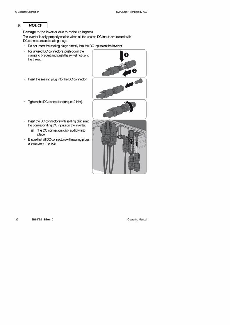
9.
Damage to the inverter due to moisture ingressThe inverter is only properly sealed when all the unused DC inputs are closed with DC connectors and sealing plugs.
• Do not insert the sealing plugs directly into the DC inputs on the inverter.
• For unused DC connectors, push down the clamping bracket and push the swivel nut up to the thread.
• Insert the sealing plug into the DC connector.
• Tighten the DC connector (torque: 2 Nm).
• Insert the DC connectors with sealing plugs into the corresponding DC inputs on the inverter.
The DC connectors click audibly into place.
• Ensure that all DC connectors with sealing plugs are securely in place.

Operating Manual SB3-5TL-21-BE-en-10 33
SMA Solar Technology AG 7 Initial Start-Up
7 Initial Start-Up
7.1 Procedure
Einl.Satz_VorgehensweiseBefore you commission the inverter, you must check various settings and make changes if necessary. This section describes the procedure for initial start-up and provides an overview of the steps that must always be performed in the given sequence.
7.2 Configuring the Country Data Set
A display language is assigned to every country data set. Configure the country data set with the associated display language so it is appropriate for your country or purpose. If the display language does not match the required language, you can change it after commissioning (see Section 8.2, page 41).The country data set must be set correctly.
1. Determine the rotary switch position for your country and purpose. Call up the Technical Information "Overview of Rotary Switch Positions" at www.SMA-Solar.com.
Procedure See
1. Check which country data set the inverter is set to. Supplementary sheet with the default settings, type label or display
2. If the country data set is not set correctly for your country or your purpose, adjust to the required country data set and corresponding display language.
Section 7.2, page 33
3. If the inverter is to communicate with multiple Bluetooth devices or if Bluetooth is not to be used as the type of communication, adjust the NetID.
Section 7.3, page 34
4. Commission the inverter and start a self-test, if required. Section 7.4, page 36 and Section 7.5, page 37
The country data set must be set correctly.
If you configure a country data set that is not valid for your country or purpose, it can cause a disturbance in the PV system and lead to problems with the grid operator. When selecting the country data set, you must always observe the locally applicable standards and directives as well as the properties of the PV system (e.g. PV system size, grid-connection point).
• If you are not sure which country data set is valid for your country or purpose, contact your grid operator and ask which country data set should be configured.
4 8 $ / ,) ,( ' 3( 562 1
4 8 $ / ,) ,( ' 3( 562 1

34 SB3-5TL-21-BE-en-10 Operating Manual
7 Initial Start-Up SMA Solar Technology AG
The inverter will adopt the setting after commissioning. This can take up to five minutes.
7.3 Setting the NetID
By default, the NetID is set to 1 for all SMA inverters and SMA communication products with Bluetooth. If your PV system consists of one inverter and no more than one other Bluetooth device (e.g. computer with Bluetooth or SMA communication product), you can leave the NetID set to 1.
You must change the NetID in the following cases:
• If your PV system consists of one inverter and two other Bluetooth devices (e.g. computer with Bluetooth interface and SMA communication product) or multiple inverters with Bluetooth, you must change the NetID of your PV system. That enables communication with multiple Bluetooth devices.
• If there is another PV system with Bluetooth within 500 m of your PV system, you must change the NetID of your PV system. This will help separate both PV systems from each other.
• If you do not want to communicate using Bluetooth, deactivate communication via Bluetooth on your inverter. This protects your system from unauthorized access.
All Bluetooth devices in one PV system must have the same NetID. Before commissioning, you can set a new NetID in the inverter by using rotary switch C. The setting is adopted after commissioning. This can take up to five minutes.
2.
Danger to life due to high voltages• Ensure that the inverter is open and no voltage is present (see Section 10, page 47).
3. Set the rotary switches A and B to the required position using a flat-blade screwdriver (blade width: 2.5 mm).
4 8 $ / ,) ,( ' 3( 562 1

Operating Manual SB3-5TL-21-BE-en-10 35
SMA Solar Technology AG 7 Initial Start-Up
Procedure:
The inverter will adopt the setting after commissioning. This can take up to five minutes.
Figure 8: Rotary switch C positions
Item Explanation
0 Bluetooth communication is deactivated.
1 Communication via Bluetooth with another Bluetooth device
2 to F NetID for communication via Bluetooth with multiple Bluetooth devices
1.
Danger to life due to high voltages• Ensure that the inverter is disconnected from all voltage sources (see Section 10, page 47).
2. To configure a new NetID, set rotary switch C to the determined NetID using a flat-blade screwdriver (blade width: 2.5 mm).
3. To deactivate the communication via Bluetooth, set rotary switch C to the position 0 using a flat-blade screwdriver (blade width: 2.5 mm). This protects your PV system from unauthorized access.

36 SB3-5TL-21-BE-en-10 Operating Manual
7 Initial Start-Up SMA Solar Technology AG
7.4 Commissioning the Inverter for the First Time
When commissioning the inverter for the first time, proceed as follows.
Requirements:
The inverter must be correctly mounted.
The circuit breaker must be correctly rated and mounted.
All cables must be correctly connected.
Unused DC inputs must be sealed using the corresponding DC connectors and sealing plugs.
The country data set must be configured according to the country or purpose.
Procedure:
1. Mount the lower enclosure lid:
• Place the lower enclosure lid on the enclosure and secure with screw 6.
2. If an ESS is used, the ESS has to be plugged in firmly. The ESS must be aligned parallel to and flush with the enclosure.
3. Attach the enclosed warning label "Risk of burns from electric arc" so that it is clearly visible on the disconnection device on the AC side.
4. Switch on the circuit breaker.
5. If an external DC load-break switch is installed, switch it on.
6. If the multi-function relay is used, switch on the load supply voltage, if necessary.
The start-up phase is beginning.
• Then tighten all six screws with an Allen key (AF 3) in the order 1 to 6 (torque: 2 Nm).
Currents in the DC cabling after connecting the ESS
After connecting the ESS, DC currents may occur in the DC cabling, even when there is no AC-side supply. This is not an error but normal behavior of the inverter when in operation.
4 8 $ / ,) ,( ' 3( 562 1

Operating Manual SB3-5TL-21-BE-en-10 37
SMA Solar Technology AG 7 Initial Start-Up
The green LED is glowing and the display alternates automatically between the device type, firmware version, the serial number or designation of the inverter, the NetID, the configured country data set and the display language.
The green LED is flashing?
Possible cause of error: the DC input voltage is still too low, or the inverter is monitoring the utility grid.
• Once the DC input voltage is sufficiently high and the grid connection conditions are met, the inverter will start operation.
The red LED is glowing and an error message and event number appear in the display?
An error has occurred.
• Rectify the error (for troubleshooting see service manual at www.SMA-Solar.com).
7.5 Self-Test in Accordance with CEI 0-21 for PV systems ≤ 6 kW
7.5.1 Starting the Self-Test
The self-test is only required for inverters, which are commissioned in Italy. The Italian standard requires that all inverters feeding into the utility grid are equipped with a self-test function in accordance with CEI 0-21. During the self-test, the inverter will consecutively check the reaction times for overvoltage, undervoltage, maximum frequency and minimum frequency.
The self-test changes the upper and lower trip-limit values for each protective function on a linear basis for frequency monitoring and voltage monitoring. As soon as the measured value exceeds the permitted trip-limit value, the inverter disconnects from the utility grid. In this way, the inverter determines the reaction time and checks itself.
Self-test in accordance with CEI 0-21 during initial start-up (applies to Italy only)
The Italian standard prescribes that an inverter can only operate on the utility grid after the disconnection times for overvoltage, undervoltage, minimum frequency and maximum frequency have been checked.
• If the country data set is configured to CEI 0-21 Int / CEI 0-21 internal, start the self-test as soon as the display shows the country data set (see Section 7.5.1, page 37).
The self-test only applies to inverters that are configured with the country data set CEI 0-21 Int or CEI 0-21 internal.
The self-test is only valid for inverters licensed for Italy and configured with the country data set CEI 0-21 Int or CEI 0-21 internal.
If the inverter is configured to the country data set CEI 0-21 Ext or CEI 0-21 external, no self-test is required.
4 8 $ / ,) ,( ' 3( 562 1

38 SB3-5TL-21-BE-en-10 Operating Manual
7 Initial Start-Up SMA Solar Technology AG
After the self-test has been completed, the inverter automatically switches back to the feed-in operation, resets the original shutdown conditions and connects to the utility grid. The test takes approx. three minutes.
Requirements:
Configured country data set: CEI 0-21 Int or CEI 0-21 internal or amended country data set trimmed or special setting based on one of the country data sets mentioned above.
A report for entering the test results according to CEI 0-21 must be available.
The inverter must be in operation and in the start phase.
Procedure:
1. As soon as the configured country data set appears in the display, tap once on the display within ten seconds.
A message informing you that the self-test has started is shown in the display: Avvio Autotest.
The message Avvio Autotest is not shown in the display?
Ten seconds have passed and the self-test has not started.
• Restart the self-test (see Section 7.5.2, page 39).
2. Tap on the display within 20 seconds and enter the test results that follow into the test report.
The self-test starts.
The inverter displays the results of the individual tests for overvoltage, undervoltage, maximum frequency and minimum frequency. The results are displayed three times in succession for ten seconds each.
The information Autotest interroto is shown in the display?
The self-test was cancelled due to an unexpected disconnection condition or the DC voltage was too low so that the grid feed-in could not continue.
• Restart the self-test (see Section 7.5.2, page 39).
Example: Display messages for overvoltage test
- Name of the test: Autotest (59.S1) 240.00V
- Disconnection value: Valore di soglia con 230.00V
- Normative value: Va. taratura 253.00V
- Disconnection time: Tempo die intervento 0.02 s
- Current line voltage: Tensione di rete Val.eff.: 229.80V

Operating Manual SB3-5TL-21-BE-en-10 39
SMA Solar Technology AG 7 Initial Start-Up
7.5.2 Restarting the Self-Test
1. Disconnect the circuit breaker and secure against reconnection.
2. If the multi-function relay is used, switch off the load supply voltage, if necessary.
3. If an external DC load-break switch is in use, switch it off for five minutes and then switch it on again.
4. If an ESS is in use, pull it out of the inverter for five minutes and then plug it in again firmly.
5. Recommission the inverter.
The inverter is now back in the start phase and you can start the self-test once again(see Section 7.5.1, page 37).
4 8 $ / ,) ,( ' 3( 562 1

40 SB3-5TL-21-BE-en-10 Operating Manual
8 Configuration SMA Solar Technology AG
8 Configuration
8.1 Procedure
Once you have commissioned the inverter, you may have to adjust various settings via the rotary switches in the inverter or via a communication product. This section describes the procedure for configuration and gives an overview of the steps you must perform in the prescribed order.
Procedure See
1. If the display language is not set correctly, adjust the settings.
Section 8.2, page 41
2. If the inverter is equipped with a Speedwire/Webconnect data module, integrate the inverter in a Speedwire network and register it in Sunny Portal, if necessary.
Communication interface manual at www.SMA-Solar.com
3. Capture the inverter in a communication product in order to manage the PV system data or to set the inverter parameters.
Manual of the communication product at www.SMA-Solar.com
4. Change the PV system time and PV system password. Manual of the communication product at www.SMA-Solar.com
5. If the inverter was installed in a network such as anIT network, deactivate the grounding conductor monitoring.
Section 8.4, page 42
6. Activate and set SMA OptiTrac Global Peak for partially shaded PV modules.
Section 8.5, page 43
4 8 $ / ,) ,( ' 3( 562 1

Operating Manual SB3-5TL-21-BE-en-10 41
SMA Solar Technology AG 8 Configuration
8.2 Changing the Display Language
If the language associated with the country data set is not your desired language, you can change the display language according to the following procedure.
2. Determine the rotary switch setting for the desired display language. Call up the Technical Information "Overview of Rotary Switch Positions" at www.SMA-Solar.com.
4. Set the rotary switch B to the required language using a flat-blade screwdriver(blade width: 2.5 mm).
5. Recommission the inverter (see Section 11, page 49).
The inverter adopts the settings after commissioning. This can take up to five minutes.
1.
Danger to life due to high voltages• Disconnect the inverter from all voltage sources and open the enclosure lid
(see Section 10, page 47).
3. Set rotary switch A to 0 using a flat-blade screwdriver (blade width: 2.5 mm). This ensures that the country data set remains unchanged.
4 8 $ / ,) ,( ' 3( 562 1

42 SB3-5TL-21-BE-en-10 Operating Manual
8 Configuration SMA Solar Technology AG
8.3 Changing Operating Parameters
This section describes the basic procedure for changing operating parameters. Change operating parameters always as described in this section. Some parameters that have sensitive functions can only be seen and changed by qualified persons (for further information on changing parameters,refer to the communication product manual).
The operating parameters of the inverter are set to certain values by default. You can change the operating parameters using a communication product to optimize the operation properties of the inverter (for a description of the operating parameters, see Technical Description "Measured Values and Parameters" at www.SMA-Solar.com).
Requirements:
Depending on the type of communication, a computer with a Bluetooth or Ethernet interface must be available.
A communication product corresponding to the type of communication used must be available.
The inverter must be registered in the communication product.
The changes to the grid-relevant operating parameters must be approved by the responsible grid operator.
To change grid-relevant parameters, the SMA Grid Guard code must be available (see Certificate "Application for SMA Grid Guard Code" at www.SMA-Solar.com).
Procedure:
1. Access the user interface of the communication product or software and log in as a user or as an installer.
2. If necessary, enter the SMA Grid Guard code.
3. Select and set the required parameter.
4. Save the setting.
8.4 Deactivating Grounding Conductor Monitoring
If the inverter is installed in an IT network or another grid configuration where it makes sense to deactivate the grounding conductor monitoring, deactivate it as follows.
The basic procedure for changing operating parameters is explained in another section(see Section 8.3, page 42).
• Set the parameter PE connection monitoring or PEOpnMon to Aus or Off.
4 8 $ / ,) ,( ' 3( 562 1
4 8 $ / ,) ,( ' 3( 562 1

Operating Manual SB3-5TL-21-BE-en-10 43
SMA Solar Technology AG 8 Configuration
8.5 Activating and Setting SMA OptiTrac Global PeakFor partially shaded PV modules, you should activate SMA OptiTrac Global Peak and set the interval at which the inverter optimizes the MPP of the PV system. The basic procedure for changing operating parameters is explained in another section(see Section 8.3, page 42).
Procedure:
1. Select the parameter OptiTrac Global Peak switched on or MPPShdw.IsOn and set to On.
2. Select the parameter Cycle time of the OptiTrac Global Peak algorithm or MPPShdw.CycTms and set the required time interval. The ideal time interval is usually six minutes. This value should only be increased if the shading situation changes extremely slowly.
The inverter optimizes the MPP of the PV system at the predetermined time interval.

44 SB3-5TL-21-BE-en-10 Operating Manual
9 Operation SMA Solar Technology AG
9 Operation
9.1 Display OverviewAufgabe_DisplayThe display shows the current operating data of the inverter (e.g. current power, daily energy, total energy) as well as events or errors. Power and energy are displayed as bars in the diagram.There is a slot for an SD card on the left edge of the display enclosure. You can use the SD card to carry out an inverter firmware update, for example (for information on firmware updates with an SD card see the technical description "Firmware Update with SD Card" at www.SMA-Solar.com).
Figure 9: Display layout (example)
Item Symbol Explanation
A - Current power
B - Energy on the current day
C - Total amount of energy fed in until now

Operating Manual SB3-5TL-21-BE-en-10 45
SMA Solar Technology AG 9 Operation
D Active Bluetooth connection
Quality of the Bluetooth connection
Active connection to a Speedwire network
Active connection to Sunny Portal
Multi-function relay is active
Power limitation due to excessive temperature
Active power limitation via PV system control
E - Indicates which line conductor the displayed values are assigned to
F Utility grid
G - Event number of an error on the utility grid side
H - Output voltage or output current of a line conductor
I - Event number of an error present on the inverter
K Grid relay
If the grid relay is closed, the inverter is feeding into the utility grid.
If the grid relay is open, the inverter is disconnected from the utility grid.
L Inverter
M - Input voltage or input current of a line conductor
N - Event number of an error on the PV array side
O - Text line to display event and error messages
P PV array
Item Symbol Explanation

46 SB3-5TL-21-BE-en-10 Operating Manual
9 Operation SMA Solar Technology AG
9.2 Activating and Operating the DisplayYou can activate and operate the display by tapping on the enclosure lid.
1. Activate the display. Tap on the enclosure lid once.
The backlight is switched on.
2. To move to the next line, tap on the enclosure lid once.
3. In order to switch between the power curve of the last 16 feed-in hours and the energy yields of the last 16 days in the diagram, tap on the enclosure lid once.
9.3 Calling Up Display Messages of the Start PhaseVarious inverter information is displayed during the start phase that can be called up whenever required during operation.
• Tap twice on the enclosure lid. The display alternates automatically between the device type, the firmware version, the serial
number or designation of the inverter, the NetID, the configured country data set and the display language.
Q - Diagram with the power curve of the last 16 feed-in hours or energy yields of the last 16 days
• In order to switch between the displays, tap once on the enclosure lid.
R You can operate the display by tapping on the enclosure lid (see Section 9.2, page 46).
The displayed error must be rectified on-site by a qualified person.
The displayed error cannot be rectified on-site.
• Contact the SMA Service Line.
Item Symbol Explanation

Operating Manual SB3-5TL-21-BE-en-10 47
SMA Solar Technology AG 10 Disconnecting the Inverter from Voltage Sources
10 Disconnecting the Inverter from Voltage Sources
Prior to performing any work on the inverter always disconnect it from all voltage sources as described in this section.
WaHiw_Zerstörung des Messgeräts durch Überspannung
Procedure:
1. Disconnect the circuit breaker and secure against reconnection.
2. If an additional DC load-break switch is available, switch off the DC load-break switch and secure against re-connection.
3. If the ESS is plugged in, remove the ESS.
4. If the multi-function relay is used, switch off the load supply voltage, if necessary.
5. Wait until the LEDs, display and if necessary, the load connected to the multi-function relay, are switched off.
6. Use a current clamp to ensure that no current is present in the DC cables.
7. Remove all six screws of the lower enclosure lid using an Allen key (AF 3) and remove the enclosure lid.
Damage to the seal of the enclosure lid during sub-zero conditionsIf you open the upper and lower enclosure lid during sub-zero conditions, the seal of the enclosure can be damaged. As a result, moisture can penetrate the inverter.
• Do not open the inverter at ambient temperatures lower than -5C.
• If a layer of ice has formed on the seal of the lid in sub-zero conditions, remove it prior to opening the inverter (e.g. by melting the ice with warm air). Observe the applicable safety regulations.
Destruction of the measuring device due to overvoltage• Only use measuring devices with a DC input voltage range up to 1,000 V.
4 8 $ / ,) ,( ' 3( 562 1
48 SB3-5TL-21-BE-en-10 Operating Manual
10 Disconnecting the Inverter from Voltage Sources SMA Solar Technology AG
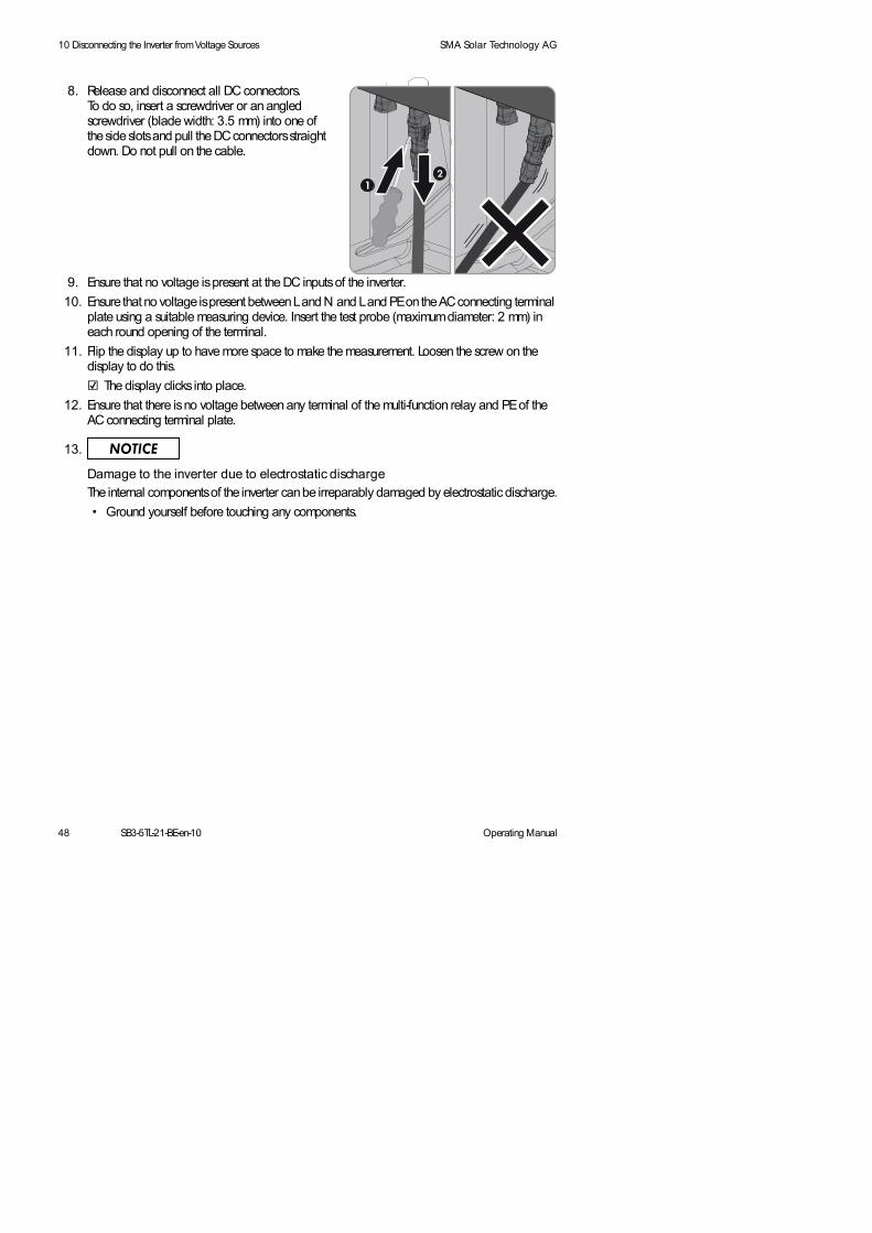
9. Ensure that no voltage is present at the DC inputs of the inverter.
10. Ensure that no voltage is present between L and N and L and PE on the AC connecting terminal plate using a suitable measuring device. Insert the test probe (maximum diameter: 2 mm) in each round opening of the terminal.
11. Flip the display up to have more space to make the measurement. Loosen the screw on the display to do this.
The display clicks into place.
12. Ensure that there is no voltage between any terminal of the multi-function relay and PE of the AC connecting terminal plate.
8. Release and disconnect all DC connectors. To do so, insert a screwdriver or an angled screwdriver (blade width: 3.5 mm) into one of the side slots and pull the DC connectors straight down. Do not pull on the cable.
13.
Damage to the inverter due to electrostatic dischargeThe internal components of the inverter can be irreparably damaged by electrostatic discharge.
• Ground yourself before touching any components.

Operating Manual SB3-5TL-21-BE-en-10 49
SMA Solar Technology AG 11 Recommissioning the Inverter
11 Recommissioning the Inverter
If you have disconnected the inverter from all voltage sources (e.g. for configuration purposes) and want to recommission it, proceed as follows.
Requirements:
The circuit breaker must be correctly rated.
The inverter must be correctly mounted.
Procedure:
1. Connect the DC connectors to the inverter.
The DC connectors click audibly into place.
3. Ensure that all DC connectors are securely in place.
4. Mount the lower enclosure lid:
• Place the lower enclosure lid on the enclosure and secure with screw 6.
5. If an ESS is used, make sure that it is not worn out (see service manual at www.SMA-Solar.com).
2. Seal all unused DC inputs using the DC connectors with sealing plugs.
• Then tighten all six screws with an Allen key (AF 3) in the order 1 to 6 (torque: 2 Nm).
4 8 $ / ,) ,( ' 3( 562 1

50 SB3-5TL-21-BE-en-10 Operating Manual
11 Recommissioning the Inverter SMA Solar Technology AG
6. If an ESS is used, the ESS has to be plugged in firmly. The ESS must be aligned parallel to and flush with the enclosure.
7. If an external DC load-break switch is installed, switch it on.
8. Switch on the circuit breaker.
9. If the multi-function relay is used, switch on the load supply voltage, if necessary.
The green LED is glowing and the display alternates between the device type, the firmware version, the serial number or designation of the inverter, the NetID, the configured country data set and the display language.
Green LED is flashing?
Possible cause of error: the DC input voltage is still too low, or the inverter is monitoring the utility grid.
• Once the DC input voltage is sufficiently high and the grid connection conditions are met, the inverter will start operation.
The red LED is glowing and an error message and event number appear in the display?
An error has occurred.
• Rectify the error (for troubleshooting see service manual at www.SMA-Solar.com).
Currents in the DC cabling after connecting the ESS
After connecting the ESS, DC currents may occur in the DC cabling, even when there is no AC-side supply. This is not an error but normal behavior of the inverter when in operation.

Operating Manual SB3-5TL-21-BE-en-10 51
SMA Solar Technology AG 12 Decommissioning the Inverter
12 Decommissioning the Inverter
2. Remove the AC cable from the inverter.
3. If the multi-function relay or the SMA Power Control Module are used, remove the connection cable from the inverter.
4. If other cables (e.g. data cables or network cables) are connected, remove them from the inverter.
5. Mount the lower enclosure lid:
• Place the lower enclosure lid on the enclosure and secure with screw 6.
6. If an ESS is used, the ESS has to be plugged in firmly. The ESS must be aligned parallel to and flush with the enclosure.
Risk of injury when lifting the inverter, or if it is droppedThe inverter is heavy (see Section 13 "Technical Data", page 53). There is risk of injury if the inverter is lifted incorrectly or dropped while being transported or when attaching it to or removing it from the wall mounting bracket.
• Transport and lift the inverter upright.
1.
Danger to life due to high voltages• Disconnect the inverter from all voltage sources (see Section 10, page 47).
• Then tighten all six screws with an Allen key (AF 3) in the order 1 to 6 (torque: 2 Nm).
7.
Risk of burns due to hot enclosure parts• Wait 30 minutes for the enclosure to cool down.
4 8 $ / ,) ,( ' 3( 562 1

52 SB3-5TL-21-BE-en-10 Operating Manual
12 Decommissioning the Inverter SMA Solar Technology AG
9. If the inverter is to be stored or shipped in packaging, pack the inverter and , if applicable, the ESS. Use the original packaging or packaging that is suitable for the weight and dimensions of the inverter.
10. Dispose of the inverter in accordance with the locally applicable disposal regulations for electronic waste.
8. If the inverter is protected against theft, open the padlock and remove it.

Operating Manual SB3-5TL-21-BE-en-10 53
SMA Solar Technology AG 13 Technical Data
13 Technical Data
13.1 DC/ AC
13.1.1 Sunny Boy 3000TL / 3600TL
DC Input
AC Output
SB 3000TL-21 SB 3600TL-21
Maximum DC power at cos = 1 3,200 W 3,880 W
Maximum input voltage 750 V 750 V
MPP voltage range 175 V to 500 V 175 V to 500 V
Rated input voltage 400 V 400 V
Minimum input voltage 125 V 125 V
Initial input voltage 150 V 150 V
Maximum input current 30 A 30 A
Maximum input current per string*
* Maximum permitted current allowed through one DC connector.
15 A 15 A
Number of independent MPP inputs 2 2
Strings per MPP input 2 2
SB 3000TL-21 SB 3600TL-21
Rated power at 230 V, 50 Hz 3,000 W 3,680 W
Maximum apparent AC power 3,000 VA 3,680 VA
Rated grid voltage 230 V 230 V
Nominal AC voltage 220 V/ 230 V/240 V
220 V/ 230 V/240 V
AC voltage range* 180 V to 280 V 180 V to 280 V
Nominal AC current at 220 V 13.6 A 16.0 A
Nominal AC current at 230 V 13.0 A 16.0 A
Nominal AC current at 240 V 12.5 A 15.3 A
Maximum output current 16 A 16 A

54 SB3-5TL-21-BE-en-10 Operating Manual
13 Technical Data SMA Solar Technology AG
Efficiency
Total harmonic distortion of the output current with total harmonic distortion of the AC voltage < 2%, and AC power > 50% of the rated power
≤ 4% ≤ 4%
Rated power frequency 50 Hz 50 Hz
AC power frequency* 50 Hz / 60 Hz 50 Hz / 60 Hz
Operating range at AC power frequency 50 Hz 45 Hz to 55 Hz 45 Hz to 55 Hz
Operating range at AC power frequency 60 Hz 55 Hz to 65 Hz 55 Hz to 65 Hz
Power factor at rated power 1 1
Displacement power factor cos , adjustable 0.8 underexcited to 1 to 0.8 overexcited
0.8 underexcited to 1 to 0.8 overexcited
Feed-in phases 1 1
Connection phases 1 1
Overvoltage category in accordance with IEC 60664-1
| | | | | |
* Depending on the configured country data set
SB 3000TL-21 SB 3600TL-21
Maximum efficiency, max 97.0% 97.0%
European efficiency, EU 96.0% 96.4%
SB 3000TL-21 SB 3600TL-21

Operating Manual SB3-5TL-21-BE-en-10 55
SMA Solar Technology AG 13 Technical Data
13.1.2 Sunny Boy 4000TL / 5000TL
DC Input
AC Output
SB 4000TL-21 SB 5000TL-21
Maximum DC power at cos = 1 4,200 W 5,200 W
Maximum input voltage 450 V 550 V
MPP voltage range 175 V to 500 V 175 V to 500 V
Rated input voltage 400 V 400 V
Minimum input voltage 125 V 125 V
Initial input voltage 150 V 150 V
Maximum input current 30 A 30 A
Maximum input current per string*
* Maximum permitted current allowed through one DC connector.
15 A 15 A
Number of independent MPP inputs 2 2
Strings per MPP input 2 2
SB 4000TL-21 SB 5000TL-21
Rated power at 230 V, 50 Hz 4,000 W 4,600 W
Maximum apparent AC power 4,000 VA 5,000 VA
Rated grid voltage 230 V 230 V
Nominal AC voltage 220 V/ 230 V/240 V
220 V/ 230 V/240 V
AC voltage range* 180 V to 280 V 180 V to 280 V
Nominal AC current at 220 V 18.2 A 20.9 A
Nominal AC current at 230 V 17.4 A 20.0 A
Nominal AC current at 240 V 16.7 A 19.2 A
Maximum output current 22 A 22 A
Total harmonic distortion of the output current with total harmonic distortion of the AC voltage < 2%, and AC power > 50% of the rated power
≤ 4% ≤ 4%
Rated power frequency 50 Hz 50 Hz

56 SB3-5TL-21-BE-en-10 Operating Manual
13 Technical Data SMA Solar Technology AG
Efficiency
13.2 General Data
AC power frequency* 50 Hz / 60 Hz 50 Hz / 60 Hz
Operating range at AC power frequency 50 Hz 45 Hz to 55 Hz 45 Hz to 55 Hz
Operating range at AC power frequency 60 Hz 55 Hz to 65 Hz 55 Hz to 65 Hz
Power factor at rated power 1 1
Displacement power factor cos , adjustable 0.8 underexcited to 1 to 0.8 overexcited
0.8 underexcited to 1 to 0.8 overexcited
Feed-in phases 1 1
Connection phases 1 1
Overvoltage category in accordance withIEC 60664-1
| | | | | |
* Depending on the configured country data set
SB 4000TL-21 SB 5000TL-21
Maximum efficiency, max 97.0% 97.0%
European efficiency, EU 96.4% 96.5%
Width x height x depth, with Electronic Solar Switch
490 mm x 519 mm x 185 mm
Weight 26 kg
Length x width x height of the packaging 597 mm x 617 mm x 266 mm
Transport weight 30 kg
Climatic category in accordance with IEC 60721-3-4
4K4H
Operating temperature range − 25C to +60C
Maximum permissible value for relative humidity, non-condensing
100%
Maximum operating altitude above MSL 2.000 m
Typical noise emission 25 dB(A)
Power loss in night mode < 1 W
SB 4000TL-21 SB 5000TL-21

Operating Manual SB3-5TL-21-BE-en-10 57
SMA Solar Technology AG 13 Technical Data
13.3 Protective Devices
Maximum data volume per inverter with Speedwire/ Webconnect
550 MB/ month
Additional data volume when using the Sunny Portal Live interface
660 kB/ hour
Topology Transformerless
Cooling concept Convection
Degree of protection for electronics in accordance with IEC 60529
IP65
Protection class in accordance with IEC 62103 |
Grid configurations* IT, Delta-IT, TN-C, TN-S, TN-C-S, split phase, TT (if UN_PE < 20 V)
National standards and approvals, as per 09/ 2013* *
AS4777, CEI 0-21, C10/ 11:2012, DIN EN 62109-1, EN 50438, G59/ 2, G83/ 1-1, IEC 61727, IEC 62109-2,
NRS 97-2-1, PPC, PPDS, RD 661/ 2007, RD 1699:2011, SI4777, VDE0126-1-1,
VDE0126-1-1 / UTE C15-712-1, VDE-AR-N 4105
* IT, Delta-IT: When using in these networks, the grounding conductor monitoring must be deactivated and an additional grounding connected to the inverter.
* * EN 50438: does not apply to all national appendices of EN 50438IEC 62109-2: This standard requires that either the multi-function relay in the inverter is used as fault indicator or that the inverter is connected to Sunny Portal and that the fault alert is activated in Sunny Portal.NRS 97-2-1: This standard requires a separate label attached to the AC distribution board, which indicates the AC-side disconnection of the inverter in case of a grid failure (for further details, see NRS 97-2-1, Sect. 4.2.7.1 and 4.2.7.2)RD 661/ 2007, RD 1699: 2011: Contact the SMA Service Line for restrictions in specific regions.
DC reverse polarity protection Short-circuit diode
Input-side disconnection device Electronic Solar Switch
DC overvoltage protection Thermally monitored varistors
AC short-circuit current capability Current control
Grid monitoring SMA Grid Guard 3
Maximum permissible fuse protection for SB 3000TL-21
25 A
Maximum permissible fuse protection for SB 3600TL-21
32 A
Maximum permissible fuse protection for SB 4000TL-21
32 A

58 SB3-5TL-21-BE-en-10 Operating Manual
13 Technical Data SMA Solar Technology AG
13.4 Climatic Conditions
According to IEC 60721-3-4, installation type C, class 4K4H
In Accordance with IEC 60721-3-4, transport type E, class 2K3
13.5 Equipment
Maximum permissible fuse protection for SB 5000TL-21
32 A
Ground-fault monitoring for SB 3000TL-21 Insulation monitoring: Riso > 625 Ω
Ground-fault monitoring for SB 3600TL-21 Insulation monitoring: Riso > 550 Ω
Ground-fault monitoring for SB 4000TL-21 Insulation monitoring: Riso > 500 Ω
Ground-fault monitoring for SB 5000TL-21 Insulation monitoring: Riso > 400 Ω
All-pole sensitive residual-current monitoring unit Available
Extended temperature range -25C to +60C
Extended humidity range 0%to 100%
Extended air pressure range 79.5 kPa to 106 kPa
Temperature range -25C to +70C
DC connection SUNCLIX DC connector
AC connection Spring-cage terminal
Display LC graphic display
Bluetooth As standard
RS485, galvanically isolated Optional
Speedwire/ Webconnect data module Optional
Multifunction relay Optional
SMA Power Control Module Optional

Operating Manual SB3-5TL-21-BE-en-10 59
SMA Solar Technology AG 13 Technical Data
13.6 Torques
13.7 Electronic Solar Switch
13.8 Data Storage Capacity
Upper lid screws 6 Nm 0.3 Nm
Screws lower lid 2 Nm 0.3 Nm
Additional grounding terminal 6 Nm
SUNCLIX swivel nut 2 Nm
RS485 communication connection 1.5 Nm
Multi-function relay connection 1.5 Nm
Electrical endurance in the event of a short circuit with a nominal current of 35 A
At least 50 switching processes
Maximum switching current 35 A
Maximum switching voltage 800 V
Maximum PV power 12 kW
Degree of protection when plugged IP65
Degree of protection when unplugged IP21
Fuses for the ESS F200, 600 V/ 4 A, fast acting and F201, 600 V/ 4 A, fast acting(soldered, not replaceable)
Energy yields over the course of the day 63 days
Daily yields 30 years
Event messages for users 250 events
Event messages for installers 250 events

60 SB3-5TL-21-BE-en-10 Operating Manual
14 Accessories SMA Solar Technology AG
14 AccessoriesYou will find relevant accessories and spare parts for your product in the following overview. If required, these can be ordered from SMA Solar Technology AG or your distributor.
Designation Short designation SMA order number
Replacement varistors Set with three thermally-monitored varistors incl. insertion tool
MSWR-TV9
Insertion tool for replacing varistors
Insertion tool for varistors SB-TVWZ
Electronic Solar Switch ESS as spare part ESS-HANDLE*
* When ordering a new ESS, always indicate the device type and serial number of the inverter.
Fan retrofit kit Fan to be installed in the inverter for supplementary cooling
FANKIT01-10
Multi-function relay retrofit kit
Multi-function relay for retrofitting in PV inverters
MFR01-10
485 Data Module 485 data module as retrofit kit DM-485CB-10
Speedwire/Webconnect data module
Speedwire/ Webconnect data module as retrofit kit
SWDM-10
Power control modules Interface for direct connection to a radio ripple control receiver, incl. multi-function relay
PWCMOD-10
SUNCLIX DC connector
Field plug for wire sizes of 2.5 mmto 6 mm
SUNCLIX-FC6-SET
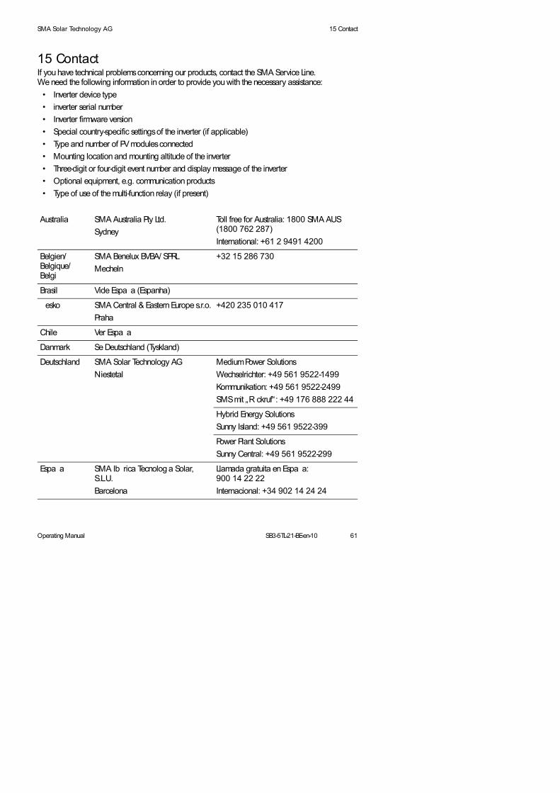
Operating Manual SB3-5TL-21-BE-en-10 61
SMA Solar Technology AG 15 Contact
15 ContactSTSatz_Kontakt_Benötigte DatenIf you have technical problems concerning our products, contact the SMA Service Line. We need the following information in order to provide you with the necessary assistance:
• Inverter device type
• inverter serial number
• Inverter firmware version
• Special country-specific settings of the inverter (if applicable)
• Type and number of PV modules connected
• Mounting location and mounting altitude of the inverter
• Three-digit or four-digit event number and display message of the inverter
• Optional equipment, e.g. communication products
• Type of use of the multi-function relay (if present)
STSatz_Kontakt_Adressen
Australia SMA Australia Pty Ltd.
Sydney
Toll free for Australia: 1800 SMA AUS(1800 762 287)
International: +61 2 9491 4200
Belgien/Belgique/Belgi
SMA Benelux BVBA/ SPRL
Mecheln
+32 15 286 730
Brasil Vide Espaa (Espanha)
esko SMA Central & Eastern Europe s.r.o.
Praha
+420 235 010 417
Chile Ver Espaa
Danmark Se Deutschland (Tyskland)
Deutschland SMA Solar Technology AG
Niestetal
Medium Power Solutions
Wechselrichter: +49 561 9522-1499
Kommunikation: +49 561 9522-2499
SMS mit „Rckruf“: +49 176 888 222 44
Hybrid Energy Solutions
Sunny Island: +49 561 9522-399
Power Plant Solutions
Sunny Central: +49 561 9522-299
Espaa SMA Ibrica Tecnologa Solar, S.L.U.
Barcelona
Llamada gratuita en Espaa: 900 14 22 22
Internacional: +34 902 14 24 24

62 SB3-5TL-21-BE-en-10 Operating Manual
15 Contact SMA Solar Technology AG
France SMA France S.A.S.
Lyon
Medium Power Solutions
Onduleurs : +33 472 09 04 40
Communication : +33 472 09 04 41
Hybrid Energy Solutions
Sunny Island : +33 472 09 04 42
Power Plant Solutions
Sunny Central : +33 472 09 04 43
India SMA Solar India Pvt. Ltd.
Mumbai
+91 22 61713888
Italien SMA Italia S.r.l.
Milano
+39 02 8934-7299
/ Kbrs / Bkz. (Yunanistan)
Luxemburg/Luxembourg
Siehe Belgien
Voir Belgique
Magyarorszg lsd esko (Csehorszg)
Nederland zie Belgien (Belgi)
sterreich Siehe Deutschland
Per Ver Espaa
Polska Patrz esko (Czechy)
Portugal SMA Solar Technology Portugal, Unipessoal Lda
Lisboa
Isento de taxas em Portugal: 800 20 89 87
Internacional: +351 212377860
Romnia Vezi esko (Cehia)
Schweiz Siehe Deutschland
Slovensko pozri esko (esk republika)
South Africa SMA Solar Technology South Africa Pty Ltd.
Centurion (Pretoria)
08600 SUNNY (08600 78669)
International: +27 (12) 643 1785
United Kingdom
SMA Solar UK Ltd.
Milton Keynes
+44 1908 304899
SMA Hellas AE
801 222 9 222
International: +30 212 222 9 222
()

Operating Manual SB3-5TL-21-BE-en-10 63
SMA Solar Technology AG 15 Contact
SMA Solar (Thailand) Co., Ltd. +66 2 670 6999
대한민국 SMA Technology Korea Co., Ltd.
서울
+82 2 508-8599
中国 SMA Beijing Commercial Company Ltd.
北京
+86 10 5670 1350
+971 2 698-5080 SMA Middle East LLC
Other countries International SMA Service Line
Niestetal
Toll free worldwide: 00800 SMA SERVICE(+800 762 7378423)
,%!%
*+%,') +%

60 $6RODU7HFKQRORJ \ $ * _6RQQHQDOOHH_1 LHVWHWDO_* HUPDQ\3KRQH_)D[_,QWHUQHWZZZ60 $GH_(PDLOLQIR# 60 $GH5HJLVWHUFRXUW$PWVJHULFKW' LVWULFWFRXUW. DVVHO+5%UHJLVWUDWLRQQXPEHU&KDLUPDQRIWKH6XSHUYLVRU\%RDUG* QWKHU&UDPHU0 DQDJLQJ%RDUG5RODQG* UHEH/\ GLD6RPPHU3LHUUH3DVFDO8UERQ0 DUNR: HUQHU
(&' HFODUDWLRQRI&RQIRUPLW\ZLWKWKH* XLGHOLQHVRIWKH(XURSHDQ
(OHFWURPDJQHWLFFRPSDWLELOLW\(&(0 &/RZYROWDJHGLUHFWLYH(&/9' 5DGLRDQGWHOHFRPPXQLFDWLRQVWHUPLQDOHTXLSPHQW(&577(
7KHSURGXFWVVWDWHGEHORZKDYHEHHQGHYHORSHGFRQVWUXFWHGDQGPDQXIDFWXUHGLQDFFRUGDQFHZLWKWKHDERYHPHQWLRQHG(&GLUHFWLYHV7KHDSSOLHGKDUPRQL]HGVWDQGDUGVDUHVKRZQLQWKHIROORZLQJWDEOH
6XQQ\ %R\ 6XQQ\ 0 LQL&HQWUDO 6XQQ\ %R\ 6XQQ\ 7ULSRZHU
6XQQ\ %R\ 6XQQ\ 7ULSRZHU
6XQQ\ %R\ 6XQQ\ 7ULSRZHU
6%7/6%7/6%7/
60 &$60 &7/5360 &7/5360 &7/53
6%7/676%7/676%7/6%7/6737/6737/6737/6737/6737/6737/
6%+)6%+)6%+)
6%7/6%7/6737/6737/6737/( (6737/6737/( (
( OHFWURP DJ QHWLF,QWHUIHUHQFH( 0 &GLUHFWLYH$ UWLFOH$ QQH[ ,D
(1
(1
(OHFWURP DJ QHWLFLQWHUIHUHQFHHP LVVLRQV( 0 &' LUHFWLYH$ UWLFOH$ QQH[ ,D
(1
(1 $$
(1
(1
,P P XQLW\ WRLQWHUIHUHQFH( 0 &' LUHFWLYH$ UWLFOH$ QQH[ ,E
( 1
(1
' HYLFHVDIHW\/9 ' $ UWLFOH$QQH[ ,
( 1
(1
)XQNP RGXO#MVFUPPUI
( 1 9
(1 9
(1 9
2 QO\ZKHQHTXLSSHGZLWK60 $#MVFUPPUI3LJ J \ %DFN
6WDQGDUGDSSOLFDEOH6WDQGDUGQRWDSSOLFDEOH
,QIRUP DWLRQ: LWKRXWDQH[SOLFLWZULWWHQFRQUPDWLRQE\60 $WKLVGHFODUDWLRQRIFRQIRUPLW\LVQRORQJHUYDOLGLIWKHSURGXFWLVPRGLHGVXSSOHPHQWHGRUFKDQJHGLQDQ\RWKHUZD\FRPSRQHQWVZKLFKDUHQRWSDUWRIWKH60 $DFFHVVRULHVNLWDUHLQWHJUDWHGLQWKHSURGXFWDVZHOODVLIWKHSURGXFWLVXVHGRULQVWDOOHGLPSURSHUO\
1 LHVWHWDO60 $6RODU7HFKQRORJ \ $*
SSD)UDQN* UHL]HU9LFH3UHVLGHQW0 373' 6%
60&673=(&(HQ

6%60&673=(%%HQ
' HFODUDWLRQRI&RQIRUP LW\ZLWK* HUP DQ(XURSHDQDQG,QWHUQDWLRQDO1 RQ(XURSHDQVWDQGDUGVXVHGIRU
68 1 1 <%2 <68 1 1 <0 ,1 ,&( 1 75$ /DQG68 1 1 <75,32 : ( 5LQYHUWHUV
* HUP DQ6WDQGDUG' ,1 ( 1
( XURSHDQ6WDQGDUG( 1
,QWHUQDWLRQDO6WDQGDUG,(&,(&&,635
' ,1 ( 1 EDVHGRQ (1 EDVHGRQ ,(&
' ,1 ( 1 EDVHGRQ (1 EDVHGRQ ,(&
' ,1 ( 1 EDVHGRQ (1 EDVHGRQ ,(&
' ,1 ( 1 EDVHGRQ (1 EDVHGRQ ,(&
' ,1 ( 1 EDVHGRQ (1 $$
EDVHGRQ ,(&$$
' ,1 (1 EDVHGRQ (1 EDVHGRQ ,(&
' ,1 ( 1 EDVHGRQ (1 EDVHGRQ ,(&
' ,1 ( 1 EDVHGRQ (1 EDVHGRQ ,(&
' ,1 ( 1 EDVHGRQ (1 EDVHGRQ ,(&
' ,1 ( 1 EDVHGRQ (1 EDVHGRQ ,(&
' ,1 ( 1 (1 9 ,(&
' ,1 ( 1 (1 9 ,(&
' ,1 ( 1 (1 9 ,(&


,
ZZZ60 $6RODUFRP60 $6RODU7HFKQRORJ \