summary of siemens safety features
TRANSCRIPT

Siemens AG, HealthcareMRsyngo MR B17dito! OHGMAGNETOM Trio a Tim SystemMR SystemOperator ManualMR2004-2009M6-03001621040102n.a.EnglishEnglish05/2009n.a.n.a.syngo MR B17
MAGNETOM Trio a Tim System 0.0
Operator Manual - MR System 0.0
syngo MR B17 0.0
www.siemens.com/healthcare

0.0
Manufacturer's notes: 0.0
This product bears a CE marking in accordance with the provisions of regulation 93/42/EEC of June 14, 1993 for medical products. 0.0
The CE marking applies only to medico-technical products/medical products introduced in connection with the above-mentioned com-prehensive EC regulation. 0.0

syngo MR B17
Overview of contents
Safety A
MR system components B
Physiological imaging C
MR system operation D
Maintenance E
Index F
0.0
0.0 i0.0

0.0
0.0ii MAGNETOM Trio a Tim System - MR System0.0

syngo MR B17
Table of contents
A Safety
A.1 Preface about safety
A.2 Information about MR safety
B MR system components
B.1 Overview MR system
B.2 syngo Acquisition Workplace
B.3 In-Room syngo Acquisition Workplace
B.4 Control unit
B.5 Laser light localizer
B.6 Alarm box
B.7 Intercom
B.8 Patient table
C Physiological imaging
C.1 Triggering methods
C.2 Physiological Measurement Unit (PMU)
C.3 ECG triggering
C.4 Pulse triggering
C.5 Respiratory triggering
C.6 External triggering
0.0
0.0iii0.0

D MR system operation
D.1 Daily functionality checks
D.2 Starting up and shutting down the MR system
D.3 Preparing the MR system
D.4 Preparing the patient
D.5 Physiological effects
D.6 Starting/Stopping the measurement
E Maintenance
E.1 Cleaning
E.2 Return and disposal
F Index
0.0
0.0iv MAGNETOM Trio a Tim System - MR System0.0

syngo MR B17
Introduction 0.0
To operate the MR system accurately and safely, the operating personnel have to have the necessary expertise as well as knowledge of the complete operator manual. The operator manual has to be read carefully prior to starting up the MR sys-tem. 0.0
Layout of the operator man-ual 0.0
Your overall operator manual includes - to improve readability - various different operator manuals separated according to their contents: 0.0
❏ Hardware components (system, coils, etc.)
❏ Software (measurement, evaluation, etc.)
Another element of the overall operator manual is the informa-tion provided for the system owner of the MR system. 0.0
The extent of the respective operator manual depends on the system configuration used and may vary. 0.0
B ���All components of the overall operator manual may include safety information that needs to be adhered to. 0.0
The operator manuals for hardware and software address the authorized user. Basic knowledge in operating PCs and software are a prerequisite. 0.0
0.0
0.0v0.0

Introduction
The operator manual on handThis manual includes descriptions covering standard as well as optional hardware. Contact your Siemens Sales Organization with respect to the hardware available for your system. The description of an option is not legally binding for providing it. 0.0
The graphics, figures, and medical images used in this operator manual are examples only. The actual display and design of these may be slightly different on your system. 0.0
Male and female patients are referred to as “the patient” for the sake of simplicity. 0.0
References to “Siemens Service” include service personnel authorized by Siemens. 0.0
Configuration
This manual consists of multiple parts (Part A, Part B, etc.). A comprehensive table of contents can be found at the beginning of each part. 0.0
B ���Part A “Safety” needs to be closely observed during your daily routine. 0.0
The other parts contain descriptive and instructive chapters. The descriptive chapters explain the design, application, and func-tion of the individual MR system components. The instructive chapters explain the operation of the individual components. 0.0
0.0
0.0vi MAGNETOM Trio a Tim System - MR System0.0

Introduction
Important icons
For readability, certain contents are highlighted in particular. In what follows you will find the symbols and their contents used:0.0
✓ Prerequisites for the operating steps to follow
✧ Request for action
❏ Item in list
B ���Notes for optimal use of the MR system. 0.0
i ���Remarks that facilitate work with the system. 0.0
f B ���Problem 0.0
Description of possible source for errors 0.0
✧ Requests for action to solve problems0.0
0.0
syngo MR B17 0.0vii0.0

Introduction
Intended useYour MAGNETOM system is indicated for use as a magnetic res-onance diagnostic device (MRDD) that produces transverse, sagittal, coronal and oblique cross sectional images, spectro-scopic images and/or spectra, and that displays the internal structure and/or function of the head, body, or extremities. Other physical parameters derived from the images and/or spec-tra may also be produced. Depending on the region of interest, contrast agents may be used. These images and/or spectra when interpreted by a trained physician yield information that may assist in diagnosis. 0.0
Your MAGNETOM system may also be used for imaging during interventional procedures when performed with MR compatible devices such as in room display and MR-safe biopsy needles. 0.0
B ���The MAGNETOM is not a measurement device as defined by the medical product guidelines. Measured values obtained are for informational purposes and cannot be used only as the basis for diagnosis. 0.0
B ���For the USA only: The device is limited by Federal Law to inves-tigational use for indications not in the Indications Statement. Federal law restricts this device to sale, distribution and use by or on the order of a physician. 0.0
0.0
0.0viii MAGNETOM Trio a Tim System - MR System0.0

Introduction
Authorized operating personnel
The MAGNETOM MR system must be operated according to the intended use and only by qualified persons with the necessary knowledge in accord with country-specific regulations, e.g. physicians, trained radiological technicians or technologists, subsequent to the necessary user training. 0.0
This user training has to include basics in MR technology as well as safe handling of MR systems. The user has to be familiar with potential hazard and safety guidelines the same way he is famil-iar with emergency and rescue scenarios. In addition, the user has to have read and understood the contents of the operator manual. 0.0
0.0
syngo MR B17 0.0ix0.0

Introduction
0.0
0.0x MAGNETOM Trio a Tim System - MR System0.0

PART 0.0 S
Asyngo MR B17
afety
A.1 Preface about safety A.1-1
General information A.1-1
A.2 Information about MR safety A.2-1
Common/permanently existing hazards A.2-1
Electromagnetic fields A.2-2
Contraindications A.2-10
Mechanical hazards A.2-13
MR compatibility A.2-16
What else must be observed? A.2-18
Ambient conditions A.2-18
Coils/quality assurance A.2-19
Patient care A.2-20
Artifacts and imaging errors A.2-22
Maintenance/repair A.2-29
Signs and symbols A.2-30
In case of emergency A.2-34
Emergency switches A.2-34
Medical emergency A.2-38
Coolant accidents A.2-39
Fire A.2-40
0.0
0.0A-10.0

Safety
0.0
0.0A-2 MAGNETOM Trio a Tim System - MR System0.0

CHAPTER A.0 P
A.1syngo MR B17
reface about safety
General information A.1
Hazards and risks A.1 An MR system may present various hazards. Some occur only during the examination, while others exist permanently and thus are also relevant to non-users (e.g. cleaning personnel). A.1
The various hazards and the corresponding safety instructions are explained in the safety chapter of this operator manual. A.1
Common causes for acci-dents A.1
Despite safety instructions, some hazards time and again lead to accidents. In particular, this includes magnet accidents and RF burns/loop formation, as well as the use of MR-incompatible devices. A.1
The following sections provide information on how to avoid the most common mistakes and the resulting safety risks. These sections were prepared based on the long-time experience of Siemens. A.1
Responsibility, use accord-ing to operator manual A.1
Siemens accepts no responsibility for the safety, reliability, and performance of the MR system, if the MR system is not used in accordance with the operator manual. A.1
0.0
0.0A.1-10.0

Preface about safety Safety
Configuration of hazard hints A.1
All hazard hints are identified in a special way. The following keywords signal the level of hazard involved: A.1
A.1
Example: A.1
A.1
WARNING A.1 Warning regarding risks that may result in death or serious physical injury. A.1
CAUTION A.1 Warning regarding risks that may result in minor physical injury or material damage. A.1
A.1
WARNING A.1
Source of danger! A.1
Consequences A.1
✧ Countermeasure.
0.0
0.0A.1-2 MAGNETOM Trio a Tim System - MR System0.0

CHAPTER A.1 I
A.2 ssyngo MR B17
nformation about MR afety
Common/permanently existing hazards A.2
The frequency at which the potential hazards mentioned in this section lead to accidents is still too high. Therefore, it is espe-cially important to observe the instructions on how to avoid these dangerous situations. A.2
The most significant hazards include: A.2
❏ Electromagnetic fields
❏ Contraindications
❏ Mechanical hazards
❏ Incompatible devices
0.0
0.0A.2-10.0

Information about MR safety Safety
Electromagnetic fields A.2
In the examination room, there are different kinds of electro-magnetic fields and the resulting risks. A.2
A.2
B A��All persons (e.g. patients, physicians, operating and cleaning personnel, accompanying persons, and rescue personnel/fire fighters) are exposed to these fields in the examination room. A.2
✧ Observe prohibition signs in the area near the entrances to the MR system and the control area.
Fields A .2 Most significant hazards A .2
Static magnetic field A.2 Movement by implants and prostheses in the body A.2
Attraction, alignment, and projectile-like acceleration of mag-netizable objects A.2
(→ Page A.2-4 Safety instructions on the static magnetic field)A.2
Gradient fields A.2 Peripheral nerve stimulation A.2
(→ Page A.2-7 Safety instructions on RF and gradient fields) A.2
RF fields A.2 Warming of body tissue A.2
(→ Page A.2-7 Safety instructions on RF and gradient fields) A.2
0.0
0.0A.2-2 MAGNETOM Trio a Tim System - MR System0.0

Safety Information about MR safety
Static magnetic field/control area A.2
The static basic field is generated by a superconductive magnet and may extend beyond the examination room (walls, ceilings).A.2
In order to minimize the mentioned hazards, the control area of the basic field is identified on the floor (0.5 mT line). Outside the control area, the magnetic flux density is less than 0.5 mT. (→ System owner manual) A.2
Gradient fields A.2 Linearly rising additional fields of variable strength - gradient fields - are superimposed on the static main magnetic field in three different orientations. They may cause shifts in charge in the patient's tissue and lead to peripheral nerve stimulation. A.2
RF fields A.2 The nuclear spins of the body tissue are stimulated via pulsed electromagnetic RF fields. These RF pulses are generated by an RF transmit amplifier and transferred via RF coils to the object to be measured. A.2
RF fields lead to warming of the body tissue. In this context, an important value per body weight is the specific absorption rate or SAR. (→ Page D.5-1 Physiological effects) A.2
0.0
syngo MR B17 0.0A.2-30.0

Information about MR safety Safety
Safety instructions on the static magnetic field A.2
The list of objects in this chapter is not exhaustive. It only serves as an illustration of objects that present hazards in the presence of magnetic forces. A.2
A.2
A.2
WARNING A.2
Magnetizable objects introduced into the magnetic field become projectiles! A.2
Injury to patient and operating personnel A.2
✧ Do not use resuscitation devices, for example, defibrillators or oxygen bottles, in the examination room.
✧ Do not use transport trolleys, movable beds, stretchers, etc. that consist of magnetizable parts.
✧ Do not wear or carry any magnetizable objects on your per-son, for example, watches, pens, scissors, etc.
✧ Use only proven MR-compatible accessories, parts subject to wear and tear, and disposable articles with the MR sys-tem.
✧ Use only MR-compatible tools and devices.
✧ Service work on the MR system may be performed by Sie-mens Service only.
✧ Ensure that only authorized personnel, e.g. electricians or cleaning personnel, enter the control area (0.5 mT exclu-sion zone).
✧ Keep the door to the examination room closed.
0.0
0.0A.2-4 MAGNETOM Trio a Tim System - MR System0.0

Safety Information about MR safety
A.2
Dizziness when exposed to 3 Tesla magnetic fields A.2
The high main magnetic field may cause patients to temporarily experience slight dizziness or sensory irritations. Therefore all patients must be medically monitored. A.2
A.2
A.2
WARNING A.2
Magnetizable objects introduced into the magnetic field become projectiles! A.2
Injury to patient and operating personnel A.2
✧ Inform the operating personnel about the stronger effect of forces on ferromagnetic parts or implants in 3 Tesla sys-tems.
A.2
CAUTION A.2
Numbness, dizziness or metallic taste during measurements and/or table movements in a 3 Tesla magnetic field! A.2
Reaction of fear by the patient A.2
✧ Prior to the examination, inform the patient about the pos-sible occurrence of these symptoms.
0.0
syngo MR B17 0.0A.2-50.0

Information about MR safety Safety
Device malfunctions A.2 Magnetic flux densities exceeding 0.5 mT can interfere with electronic implants or other devices. The main magnetic field may either affect or destroy electronic data carriers such as check or credit cards, hard disks, ID cards with magnetic strips and/or magnetic tapes, diskettes or pocket calculators, as well as RFID chips (Radio Frequency Identification). A.2
0.0
0.0A.2-6 MAGNETOM Trio a Tim System - MR System0.0

Safety Information about MR safety
Safety instructions on RF and gradient fields A.2
Current loops A.2 Dangerous current loops may be generated when parts of the patient's body touch. These loops may lead to burns or increase the probability of stimulation. A.2
Current loops are also generated when the patient's skin con-tacts the tunnel lining or RF coil cables. A.2
A.2
B A��Ensure that patients are not positioned as shown in the illustra-tion. A.2
0.0
syngo MR B17 0.0A.2-70.0

Information about MR safety Safety
A.2
A.2
CAUTION A.2
The patient is wearing electrically conductive material! A.2
Incorrect patient positioning! A.2
Formation of electric current loops A.2
Peripheral nerve stimulation of the patient A.2
✧ Ensure that the patient does not wear clothing that is wet or dampened by perspiration.
✧ Ensure that the patient is free of metallic rings, chains, or electrically conductive materials worked into items of cloth-ing (e.g. brassiere support wires).
✧ Always position the patient so that the patient's arms are aligned with the torso and ensure that hands, arms, and legs do not touch (minimum distance: 5 mm).
✧ Ensure that the minimum distance of 5 mm is maintained between patient and tunnel covering.
✧ To ensure this distance, use positioning aids, e.g. blankets made of linen, cotton, or paper, or dry material that is per-meable to air.
✧ Ensure sufficient ventilation.
0.0
0.0A.2-8 MAGNETOM Trio a Tim System - MR System0.0

Safety Information about MR safety
A.2
A.2
CAUTION A.2
Heating up/ignition of synthetic blankets via the RF field during the measurement! A.2
Patient burns A.2
✧ Use only covers made of paper, cotton or linen.
0.0
syngo MR B17 0.0A.2-90.0

Information about MR safety Safety
Contraindications A.2
B A��This chapter contains very important information about MR safety: In principle, a qualified physician has to evaluate the risk/benefit ratio of the MR examination for every patient. A.2
To date, there is no scientific proof that MR examinations are harmless for pregnant women, the unborn and children under two years of age. A.2
In general, an MR examination is contraindicated for patients with electronic or electronically conductive implants or metals, especially those containing ferromagnetic foreign matter. A.2
Typical contraindications for MR examinations are: A.2
❏ Electronic implants: e.g. pacemakers, stimulators, insulin pumps
❏ Artificial heart valves, aneurysm clips
❏ Metal splinters in the eye (danger of retinal detachment)
❏ Artificial anus (anus praeter) with magnetic closure
❏ Transdermal adhesive dressing
❏ Electrically conductive implants and prostheses
❏ Metallic spirals for contraception (IUDs = Intra Uterin Devices)
0.0
0.0A.2-10 MAGNETOM Trio a Tim System - MR System0.0

Safety Information about MR safety
Exceptions: Certain implanted medical devices are approved by the governing regulatory bodies to be MR conditionally safe. For such implants, the general Siemens contraindications as previ-ously mentioned may not be applicable. Please contact the implant manufacturer for the specific conditional information. The conditions for MR safety are the responsibility of the implant manufacturer, not of Siemens. A.2
A.2
Exceptions: Certain implanted medical devices are approved by the governing regulatory bodies to be MR conditionally safe. For such implants, the previously mentioned warning may not be applicable. Please contact the implant manufacturer for the spe-cific conditional information. The conditions for MR safety are the responsibility of the implant manufacturer, not of Siemens. A.2
A.2
WARNING A.2
Electronic and/or electrically conductive implants and magnetiz-able inclusions in static and low-frequency magnetic fields and RF fields! A.2
Risk of patient death/patient injury A.2
✧ Ask the patient about implants and inclusions.
✧ Do not perform MR examinations on patients with elec-tronic or electrically conductive implants and magnetizable inclusions.
✧ Ensure that patients wearing such implants and/or inclu-sions remain outside the exclusion zone (0.5 mT line).
0.0
syngo MR B17 0.0A.2-110.0

Information about MR safety Safety
A.2
A.2
A.2
CAUTION A.2
Eddy currents induced by low-frequency magnetic fields! A.2
Patient burns A.2
✧ Do not examine patients with electrically conducting implants or prostheses.
A.2
CAUTION A.2
Electrically conducting objects! A.2
Injury to patient due to warming A.2
Incorrect diagnosis due to artifacts A.2
✧ Request that the patient removes all electrically conducting objects, e.g. necklaces, rings, braces, rubber bands for long hair, piercings as well as jewelry.
✧ Request that the patient removes all clothing including electrically conducting material, e.g. bras.
✧ Inform patients that eyeliners and tattoos may contain ingredients causing artifacts or skin irritations during MR examinations. In some cases, patients have been burned.
✧ To prevent injuries, instruct patients to remove makeup prior to the examination.
✧ Instruct patients to seek medical attention in case of dis-comfort during or following the MR examination.
0.0
0.0A.2-12 MAGNETOM Trio a Tim System - MR System0.0

Safety Information about MR safety
Mechanical hazards A.2
Collision and points of injuryA.2 Collisions and injuries are more prevalent when using the exchangeable tabletop, the patient table or when performing maintenance activities. A.2
✧ Observe the warning and prohibition signs as well as the safety information.
B A��If you plan a patient intervention outside the magnet, activate the Table Stop button as a precautionary measure to avoid acci-dental patient table movement. A.2
A.2
0.0
syngo MR B17 0.0A.2-130.0

Information about MR safety Safety
A.2
CAUTION A.2
Vertical and horizontal movement of the patient table! A.2
Injury to patient and other persons A.2
Damage to the patient table A.2
✧ Explain the significance of protocol-controlled table move-ments to the patient.
✧ Ensure that there are no persons or objects within the haz-ardous zone of the patient table.
✧ Ensure that the coil, the patient's clothing or hair and the straps do not extend over or hang off the patient table or that the IV tube does not get caught and the IV needle remains in the patient during table movement.
✧ In case of hazardous conditions, press the Table Stop but-ton.
✧ Secure the patient’s arms with straps so that the patient is not caught between the tabletop and the magnet cover and remain in the MR examination room with helpless patients (e.g., children and patients who are either seriously ill, par-alyzed, unconscious, sedated, handicapped or medicated), even if the patients are secured during the examination.
✧ Keep the patient under visual or acoustic control.
0.0
0.0A.2-14 MAGNETOM Trio a Tim System - MR System0.0

Safety Information about MR safety
Hazard of falling down A.2 The hazard of falling down is related in particular to the unfavo-rable routing of cables/hoses of interventional components. A.2
A.2
A.2
CAUTION A.2
Cable/hoses of interventional components! A.2
Injury to patient and operating personnel A.2
✧ Route cables/hoses of interventional components so that it is not possible to trip over them.
0.0
syngo MR B17 0.0A.2-150.0
Information about MR safety Safety
MR compatibility A.2
Combinations with other systems, accessories A.2
Among other things, the following hazards or complications may occur through the use of third-party products during MR examinations: A.2
❏ Heating of system cables or connection cables
❏ Interference with MR image quality
❏ Malfunctioning of third-party products
If the MR system is combined with other systems or compo-nents, it has to be ensured that the planned combination and cable routing do not affect the safety of patients, personnel, or the environment. A.2
B A��Ensure that the devices used in the examination room are com-patible with the field strength of the MR system. Devices com-patible with 1.5 T systems may be unsuitable for 3 T systems. A.2
✧ Contact Siemens Service prior to combining the MR system with other devices.
✧ Ensure MR compatibility and adhere to the instructions pro-vided by Siemens Service.
0.0
0.0A.2-16 MAGNETOM Trio a Tim System - MR System0.0

Safety Information about MR safety
Interferences A.2 Peripheral equipment (e.g. patient monitoring, life support or emergency care equipment) which is not specified or recom-mended for use in the MRI environment, including the scan room, may be disturbed by the RF field or the magnetic fringe field of the MR system. This equipment may also disturb the proper function of the MR system. A.2
MR-safe A.2 MR-safe products are those that do not present additional risks to the patient or other personnel within the environment of the MR system. They can adversely affect the quality of diagnostic information. A.2
MR-compatible A.2 The following devices are rated as MR-compatible: A.2
❏ MR-safe devices
❏ Devices whose presence in the MR environment has a min-imal effect on image quality
❏ Devices that fulfill their purpose with respect to their spec-ifications safely and without interference in the MR envi-ronment
B A��Similarly, MR-compatible devices may present hazards as well. Please observe the manufacturer's operator manual to avoid potential hazards. A.2
0.0
syngo MR B17 0.0A.2-170.0

Information about MR safety Safety
What else must be observed? A.2
Ambient conditions A.2
Access to the examination room A.2
Free access to and exit from the examination room must be ensured at all times. A.2
✧ Regularly check the correct functioning of the door to the examination room.
✧ Ensure that the door to the examination room opens and closes correctly.
Regulating the room tem-perature A.2
The patient’s ability to dissipate surplus heat is increasingly affected as the room temperature and relative humidity increase. A.2
✧ Ensure that the room temperature is at max. 22 °C and the relative humidity does not exceed 60 %.
0.0
0.0A.2-18 MAGNETOM Trio a Tim System - MR System0.0

Safety Information about MR safety
Noise development A.2
The mechanical forces lead to noise development (humming, knocking noises) during the MR examination. A.2
❏ Due to an increase in tension, the permissible sound pres-sure level may be reason for concern for pregnant women and their unborn, for newborns, infants and small children as well as older persons.
❏ Anesthesized or unconscious patients have to be provided with mandatory hearing protection.
A.2
✧ For MR examinations on infants or MR examinations with head coils, use an alternative hearing protection, e.g. ear plugs.
Coils/quality assurance A.2
Safety instructions covering the intended use of coils and meas-urement phantoms are included in a separate operator manual (→ Coil operator manual). A.2
A.2
CAUTION A.2
Noise development during the MR examination! A.2
Injury to patient (hearing loss) A.2
✧ Provide the patient with appropriate hearing protection that lowers noise to 99 dB(A) (→ System owner manual).
✧ Ensure that personnel in the examination room wear hear-ing protection during the examination.
0.0
syngo MR B17 0.0A.2-190.0

Information about MR safety Safety
Patient care A.2
Patient information A.2 Patients have to be informed about the hazards and safety measures during MR examinations. Before doing so, it must be confirmed that an MR examination is permissible and/or checked if increased precautions are necessary. A.2
A.2
A.2
CAUTION A.2
Patient received insufficient clarification of facts! A.2
Injury to patient A.2
✧ Explain to the patient the conduct expected and possible risks involved.
✧ Inform the patient about the monitoring and communica-tion equipment, e.g. squeeze ball, intercom.
✧ Instruct the patient regarding possible heat development during the MR examination.
✧ Inform the patient about noise developing during the MR examination.
✧ Prior to the MR examination, instruct patients of possible stimulations during the examination, i.e. twitching mus-cles, tingling sensation.
0.0
0.0A.2-20 MAGNETOM Trio a Tim System - MR System0.0

Safety Information about MR safety
Patient monitoring A.2 Patients may be acoustically as well as visually and physiologi-cally monitored in the MR system. A.2
1. The viewing window or a video system is used for visual monitoring.
2. The intercom can be used to acoustically contact the patient. (→ Page B.7-1 Description)
3. MR-compatible monitoring devices can be used to monitor the patient's vital parameters.
B A��For some (e.g. sedated, physically unstable) patients, monitor-ing of the vital parameters with MR-compatible monitoring devices is mandatory. A.2
A.2
A.2
CAUTION A.2
MR-incompatible monitoring devices! A.2
Patient burns A.2
✧ Use only MR-compatible monitoring devices, e.g. ECG elec-trodes and pulse sensor.
0.0
syngo MR B17 0.0A.2-210.0

Information about MR safety Safety
Artifacts and imaging errors A.2
Due to their magnetizability, foreign objects in the area of the magnet bore cause strong local distortions of the basic field and lead to considerable image artifacts. Depending on the level of distortion, diagnosis may be difficult, impaired or completely impossible. A.2
Causes A.2 Artifacts and imaging errors are listed according to their source for error: A.2
❏ System-related artifacts/imaging errors
❏ Patient-related artifacts/imaging errors
❏ User-related artifacts/imaging errors (→ Software operator manual)
User-related and patient-related artifacts/imaging errors can be largely avoided through patient instructions and proper conduct of patient and personnel. A.2
System-related artifacts/imaging errors A.2
The MR image may show system-related artifacts/imaging errors despite careful preparation. A.2
✧ If the same artifact/imaging error appears repeatedly, doc-ument and submit it to Siemens Service.
0.0
0.0A.2-22 MAGNETOM Trio a Tim System - MR System0.0

Safety Information about MR safety
High field and ultra-high field A.2
A.2
Stripe artifacts A.2
A.2
A.2
CAUTION A.2
Artifacts caused by 3 Tesla magnetic fields! A.2
Incorrect diagnosis A.2
✧ MR images should be interpreted by an MR-trained physi-cian only. He must have special training in artifacts that may have been caused by a 3 Tesla magnetic field.
A.2
CAUTION A.2
RF-signal interference caused by non-MR-compatible accesso-ries, e.g. patient monitoring devices! A.2
Streaks and bright spots in the MR image A.2
✧ Use only MR-compatible accessories.
✧ Keep the door to the examination room closed.
✧ Vary the bandwidth of the MR sequence.
✧ Whenever possible, use local coils for the MR examination.
0.0
syngo MR B17 0.0A.2-230.0

Information about MR safety Safety
Incorrect slice positioning A.2
A.2
Variations in brightness A.2
A.2
A.2
CAUTION A.2
Phasing of MR signal is not set correctly! A.2
Structure is shown in the wrong position A.2
✧ Repeat the measurement for the structure in question by using a second orthogonal slice and check whether the position of the structure is reproducible nor not.
A.2
CAUTION A.2
Local variation in the sensitivity of local coils! A.2
Continuous fluctuations in MR image brightness A.2
✧ Whenever possible use a local coil with transmit character-istics that are more suitable for the “FoV” desired.
✧ Use the normalization filter.
0.0
0.0A.2-24 MAGNETOM Trio a Tim System - MR System0.0

Safety Information about MR safety
A.2
Variations in signal and con-trast A.2
A.2
A.2
CAUTION A.2
Static and/or stationary brightness errors on the LCD monitor! A.2
Incorrect diagnosis A.2
✧ Change the image to ensure that the MR image does not show differences in brightness, spots, or cloudiness.
✧ Check bright objects for afterglow.
✧ View the LCD monitor only when it is centered and in the vertical position.
A.2
CAUTION A.2
Inhomogeneous RF field! A.2
Right-left asymmetry of contrast in the MR image A.2
✧ Whenever possible use a local coil with transmit character-istics that are more suitable for the “FoV” desired.
0.0
syngo MR B17 0.0A.2-250.0

Information about MR safety Safety
Distortions/signal oblitera-tion along the edges A.2
A.2
Localization errors due to distortion A.2
A.2
A.2
CAUTION A.2
Spatial non-linearity of the gradient field and inhomogeneity of the static magnetic field! A.2
Pin-cushion and barrel-shaped distortions and/or loss of sig-nal in the margins of the MR-image A.2
✧ Go through a distortion correction.
✧ Position the region to be examined as close to the magnet isocenter as possible.
✧ Use phantoms for the control measurements.
A.2
CAUTION A.2
Incorrect localization data due to spatial non-linearity of the gra-dient field and inhomogeneity of the static magnetic field! A.2
Incorrect stereotactic planning A.2
✧ Take localization errors into account while planning stereo-tactic invasions.
0.0
0.0A.2-26 MAGNETOM Trio a Tim System - MR System0.0

Safety Information about MR safety
Potato chip artifact A.2
A.2
A.2
CAUTION A.2
Distorted slice edges in the margin due to spatial non-linearity of the gradient field and inhomogeneity of the static magnetic field! A.2
Incorrect stereotactic planning A.2
✧ When planning stereotactic invasions, take into account slice warping at the margins of the MR image. This applies in particular to graphic slice positioning (GSP) as well as other graphic slice displays and slice positioning data inde-pendent of the possible use of distortion correction.
0.0
syngo MR B17 0.0A.2-270.0

Information about MR safety Safety
Patient-related artifacts/imaging errors A.2
A.2
A.2
A.2
CAUTION A.2
Incorrect MR image! A.2
Incorrect diagnosis A.2
✧ Prior to the examination, inform patients about move-ments and their negative effects on the measurement.
✧ Ensure that the patient does not move during the measure-ment.
✧ Monitor the patient during the MR examination.
A.2
CAUTION A.2
Paradigm not followed or noticeable patient movement! A.2
Incorrect stereotactic planning A.2
✧ Prior to the examination, inform patients about move-ments and their negative effects on the measurement.
✧ Use Siemens scan protocols with motion correction.
✧ Monitor the patient to ensure that the task is performed correctly.
0.0
0.0A.2-28 MAGNETOM Trio a Tim System - MR System0.0

Safety Information about MR safety
Maintenance/repair A.2
A.2
Daily checks A.2 Windows, doors, and emergency flaps must not be blocked. A.2
Safety-relevant accessories A.2 The following safety-relevant accessories should be checked: A.2
❏ All RF coils for the transmitting and receiving system (some are optional)
❏ ECG and respiratory sensor (optional)
❏ Disposable electrodes (optional)
❏ Pulse sensor (optional)
Serious malfunctions A.2 In case of serious malfunctions, shut down the MR system immediately and notify Siemens Service. A.2
Maintenance A.2 For detailed information about maintenance of the MR system, please refer to the separate system owner manual. (→ System owner manual) A.2
A.2
WARNING A.2
High voltage and currents inside the electronics cabinets! A.2
Improper cleaning of the system! A.2
Risk of death by electrocution A.2
✧ Electronics cabinets should be opened by Siemens Service only.
✧ Clean the system with a damp cloth only.
0.0
syngo MR B17 0.0A.2-290.0

Information about MR safety Safety
Signs and symbols A.2
Warning signs A.2
A.2
A.2 A.2 A.2
NMR magnetic field A.2 RF field A.2 Observe operator manual A.2
A.2 A.2 A .2 A.2
Potential injury to persons A.2
Risk of injury A.2 Risk of breaking A .2 Laser radiation A.2
0.0
0.0A.2-30 MAGNETOM Trio a Tim System - MR System0.0

Safety Information about MR safety
A.2
A.2
A.2
Laser A.2 Laser (for the US only) A.2
A.2
A.2
Refilling with liquid nitrogen and helium A.2 A.2
0.0
syngo MR B17 0.0A.2-310.0

Information about MR safety Safety
Prohibition signs A.2 The following objects are prohibited in the examination room: A.2
A.2
A.2 A.2 A .2 A.2
Implants susceptible to electromagnetic effects A.2
Open flames, no smoking A.2
Metallic implants and other metallic objects inside the body A .2
Mechanical watches and electronic data carriers A.2
A.2 A.2 A .2
A.2
Fire extinguishers with magnetizable metal housing A.2
Metal parts, e.g. tools A.2
Electronic data carri-ers A .2
A.2
0.0
0.0A.2-32 MAGNETOM Trio a Tim System - MR System0.0

Safety Information about MR safety
A.2
Further symbols A.2
A.2
A.2A.2
Unauthorized access A.2 Implants susceptible to electromagnetic effects A.2
A.2 A .2 A.2
Sign requiring mandatory hearing protection A.2
Protective class symbol B for application parts A .2
Protective class symbol BF for application parts A.2
0.0
syngo MR B17 0.0A.2-330.0

Information about MR safety Safety
In case of emergency A.2
✧ Before working with the system, familiarize yourself with the location and functionality of the emergency switches installed.
✧ Report all accidents resulting in personal injury immedi-ately to the appropriate authorities or the employer’s liabil-ity insurance carrier.
✧ Observe the established emergency plans (e.g. emergency plan in case of coolant accidents, emergency plan for fire fighting).
Emergency switches A.2
The MR system has different types of emergency switches. A.2
A.2
Switch A .2 Effect A.2 Emergency A.2
Magnet Stop A.2 Shutting down the magnetic field (quenching) A.2
e.g. in case of accidents with attracted metal parts or in case of fire A.2
Emergency Shut-down A.2
MR system is switched off A.2 e.g. fire A.2
Table Stop A.2 Motorized table movement is stopped A.2
in case of accidents or injury due to table movement A.2
0.0
0.0A.2-34 MAGNETOM Trio a Tim System - MR System0.0

Safety Information about MR safety
In case of emergency, the relevant switch should be pressed. A.2
A.2
(1) Magnet Stop switch(2) Emergency Shut-down switch(3) Table Stop button
0.0
syngo MR B17 0.0A.2-350.0

Information about MR safety Safety
Magnet Stop switch A.2 The Magnet Stop switch triggers a controlled magnet quench (shutting down the magnetic field). The MR system is not dis-connected from the power. A.2
There are two different versions at the MR system for the Mag-net Stop switch: as an individual switch or as an integral part of the alarm box. The switches may also be installed in other places at the MR system. A.2
A.2
After the Magnet Stop switch has been pressed, an alarm is triggered at the alarm box. The MAG STOP LED will light up, and an alarm signal will sound. A.2
B A��As a rule, Siemens Service has to be called following a quench. The magnet may be put back into operation by Siemens Service personnel only. A.2
0.0
0.0A.2-36 MAGNETOM Trio a Tim System - MR System0.0

Safety Information about MR safety
A.2
Emergency Shut-down switch A.2
The Emergency Shut-down switch is a separate red switch located near the alarm box. The switch is used to switch off the entire MR system. A.2
A.2
A.2
WARNING A.2
Formation of droplets due to condensation during quenching! A.2
Personal injury A.2
Risk of fire A.2
✧ Do not touch the exhaust line.
✧ Do not stand under the exhaust line.
✧ Avoid open flames and do not smoke.
A.2
WARNING A.2
Fire or electrical accidents! A.2
Personal injury A.2
✧ Press the EMERGENCY SHUT-DOWN switch immediately.
✧ Contact your fire department.
0.0
syngo MR B17 0.0A.2-370.0

Information about MR safety Safety
Table Stop button A.2 The Table Stop button is used to stop motorized table move-ment. It is located on the control unit and on the intercom. A.2
A.2
Medical emergency A.2
A.2
A.2
WARNING A.2
Medical emergency during MR measurements! A.2
Risk of death to patients A.2
✧ Terminate the measurement immediately.
✧ Remove patients from the examination room for treatment unless it is certain that the medical equipment required is appropriate for use inside an MR room.
✧ Do not store or operate oxygen tanks, defibrillators or other auxiliary tools for resuscitation in the examination room.
0.0
0.0A.2-38 MAGNETOM Trio a Tim System - MR System0.0

Safety Information about MR safety
A.2
Coolant accidents A.2
First aid in case of shortness of breath A.2
A person becomes unconscious due to severe shortness of breath: A.2
✧ Remove unconscious persons immediately from the room.
✧ Start CPR immediately and contact a physician immedi-ately.
A.2
CAUTION A.2
Squeeze bulb is defective! A.2
Risk of injury to patient because emergencies cannot be communicated A.2
✧ Check the functionality of the squeeze bulb daily.
0.0
syngo MR B17 0.0A.2-390.0

Information about MR safety Safety
First aid in case of frostbite A.2 Direct contact with subzero liquids, gases, and surfaces (e.g. pipes) may lead to frostbite. The eyes and mucous membranes are especially vulnerable. A.2
A.2
✧ Remove clothing carefully from the locations involved.
✧ Rinse frostbitten skin with lukewarm water.
✧ Cover frostbitten skin with sterile bandages.
✧ Do not apply powder or creams.
✧ Contact a physician immediately.
Fire A.2
Fire fighting A.2 The following devices/materials may be used for fire fighting: A.2
❏ Non-magnetic CO2 extinguisher
❏ Self-contained, anti-magnetic compressed-air breathing apparatus (or hose connection)
❏ Airtight chemical protective suit
A.2
WARNING A.2
Improper handling of liquid helium! A.2
Skin damage caused by frostbite A.2
✧ Do not rub frostbitten skin areas.
0.0
0.0A.2-40 MAGNETOM Trio a Tim System - MR System0.0

PART A.2 M
Bsyngo MR B17
R system components
B.1 Overview MR system B.1-1
Super-conducting magnet B.1-1
Electronics cabinets B.1-2
RF coils B.1-4
B.2 syngo Acquisition Workplace B.2-1
Host B.2-1
Data recording B.2-2
Monitor B.2-3
Keyboard B.2-4
Mouse B.2-6
syngo MR Workplace (optional) B.2-6
B.3 In-Room syngo Acquisition Workplace B.3-1
Description B.3-1
Operation B.3-2
Operating the trackball and the keys B.3-3
Adjusting the monitor B.3-4
Operating the footswitch B.3-5
B.4 Control unit B.4-1
Control buttons B.4-2
Table display B.4-2
0.0
0.0B-10.0

MR system components
B.5 Laser light localizer B.5-1
B.6 Alarm box B.6-1
Description B.6-1
Checks B.6-3
B.7 Intercom B.7-1
Description B.7-1
Operation B.7-3
Listening to announcements made by the patient B.7-4
Transmitting live announcements to the examination room B.7-4
Transmitting automatic voice output to the examination room B.7-5
Playing music inside the examination room B.7-6
Stopping the patient table movement B.7-8
Terminating the measurement sequence B.7-8
Acknowledging the patient alert B.7-9
Listening to physiological monitoring signals B.7-9
B.8 Patient table B.8-1
Description B.8-1
Operation B.8-4
Rescuing the patient in an emergency B.8-6
0.0
0.0B-2 MAGNETOM Trio a Tim System - MR System0.0

CHAPTER B.0 O
B.1syngo MR B17
verview MR system
Super-conducting magnet B.1
Magnetic field B.1 The super-conducting magnet generates a strong homogene-ous magnetic field with a field strength of 3.0 T. B.1
Cooling system B.1 The magnet is filled with liquid helium as a coolant. Following installation, it is adjusted to the desired operating field strength. The ramped-up magnet does not require additional electric power to maintain the magnetic field. However, under normal operating conditions, liquid helium boils off slowly so that Sie-mens Service has to refill it once a year. B.1
Shielding B.1 To minimize the effects of the magnetic fringe field on the envi-ronment, the magnet of the MR system is equipped with active super-conducting shielding. B.1
Gradient system B.1 The gradient system provides precisely localizing slice positions.B.1
MAGNETOM Trio a Tim System is equipped with the whole-body gradient system TQ engine (→ System owner manual). B.1
For research purposes, your MR system may be additionally pre-pared for use with a head gradient coil. The switch-over for both gradient systems is installed at the wall behind the MR system. B.1
B B��The MR system is exclusively approved for use with whole-body gradient systems. This approval is no longer valid when the sys-tem has been switched over to the head gradient coil. Ensure that the switch-over is in the horizontal position during stand-ard patient operation (GC whole-body operation). B.1
0.0
0.0B.1-10.0

Overview MR system MR system components
Electronics cabinets B.1
The electronics cabinets are located in the engineering room or the operating room. B.1
B.1
(1) RF power amplifier(2) Gradient cabinet(3) Control cabinet(4) System separator
Gradient cabinet B.1 The gradient cabinet contains the power electronics for gener-ating the magnetic field gradients. B.1
0.0
0.0B.1-2 MAGNETOM Trio a Tim System - MR System0.0

MR system components Overview MR system
Control cabinet B.1 The control cabinet includes different electronics components to operate the MR system. B.1
The control cabinet includes a sequence-programmable, optical trigger signal output which can be made externally accessible by Siemens Service via installation of a fiber optic cable. B.1
B B��Please note that Siemens provides customers with the optical trigger signal output for research purposes only. No devices con-nected to this output have been tested by Siemens. Before con-necting devices to the MR suite using the optical trigger signal output, they have to be tested for safety by trained personnel. B.1
Before using devices in the proximity of the magnet, their non-magnetic properties and clinical operation in the magnetic field have to be confirmed. B.1
The use of devices connected to the optical trigger signal output has to comply with any applicable governmental or local hospi-tal Institutional Review Boards (IRBS). B.1
Siemens will not be held responsible for the use of any device and resulting consequences in connection with the optical trig-ger signal output. B.1
RF power amplifier B.1 The RF power amplifier provides the radio frequency signals for the MR measurement. B.1
0.0
syngo MR B17 0.0B.1-30.0

Overview MR system MR system components
RF coils B.1
The description, handling and quality measurements for RF coils are included in a separate operator manual (→ Coil operator manual). B.1
0.0
0.0B.1-4 MAGNETOM Trio a Tim System - MR System0.0

CHAPTER B.1 s
B.2 psyngo MR B17
yngo Acquisition Work-lace
B.2
The workplace in the operating room is known as syngo Acqui-sition Workplace (syngo Acq WP). It includes the host processor with the operating elements monitor, keyboard, and mouse. B.2
An additional component of the syngo Acquisition Workplace is the intercom. (→ Page B.7-1 Description) B.2
Host B.2
Among others, the host processor includes the following func-tions: B.2
❏ Patient management
❏ Image selection and storage
❏ Measurement sequence management
Starting/stopping the host processor. (→ Page D.2-1 Starting up and shutting down the MR system) B.2
i B��Measured MR images may be transferred to other systems or computers via the network connection (e.g. PACS or RIS sys-tems). MR images from other systems or computers can be received via the network as well. B.2
Information about network connections is displayed in the Info... dialog window. B.2
0.0
0.0B.2-10.0

syngo Acquisition Workplace MR system components
Data recording B.2
The MR system provides the following modules for data record-ing: B.2
❏ CD burner
❏ DVD drive
An interface (e.g. USB connection) for a paper printer is also available. B.2
The burn and read process is started via the software. (→ Software operator manual) B.2
Data carrier B.2 Only CD-Rs (Recordable) labeled “Medical Grade” and having a gold-colored layer are suitable for documenting data for medi-cal purposes. Siemens Service will provide you with CD-Rs. B.2
B B��Please note the handling, care, storage of CDs, CD-Rs, and DVDs addressed by the respective manufacturers. B.2
0.0
0.0B.2-2 MAGNETOM Trio a Tim System - MR System0.0

MR system components syngo Acquisition Workplace
Monitor B.2
The monitor is used for displaying MR images as well as user dia-logs. It is switched on or off as part of the overall MR system. B.2
All other adjustments are blocked since the monitor is already optimally configured by Siemens Service. B.2
B B��Do not touch the surface of the screen using sharp, pointed objects. B.2
Do not position containers holding fluids, e.g. cups or glasses, on top of the monitor. B.2
In addition, general cleaning remarks have to be observed. B.2
The monitor may be opened only by authorized Siemens Service personnel. B.2
0.0
syngo MR B17 0.0B.2-30.0

syngo Acquisition Workplace MR system components
Keyboard B.2
The MR system is equipped with an original Siemens keyboard. This keyboard is a modified Windows keyboard where the numeric keys have been replaced with symbol keys. B.2
The symbol keys are used to access frequently used functions. The F4, F5, F6, F7, and F8 function keys enable you to access the individual task cards. The F1 function key lets you access the Online help. B.2
B.2
Function B.2 Original Siemens key B.2 Windows key B.2
Increase/decrease image brightness B.2
(set window position) B.2
/ B.2
NUM / / B.2
Increase/decrease contrast B.2
(set the window width) B.2
/ B.2
* / - B.2
Automatically set contrast and bright-ness B.2
B.2
9 B.2
Page forth/back in the examination B.2
/ B.2
8 / 7 B.2
Page forth/back in the series B.2
/ B.2
5 / 4 B.2
Page forth/back image by image B.2
/ B.2
2 / 1 B.2
Open patient registration B.2
B.2
Ins B.2
0.0
0.0B.2-4 MAGNETOM Trio a Tim System - MR System0.0

MR system components syngo Acquisition Workplace
Selecting the Patient Browser B.2
B.2
Del B.2
Copy to film sheet B.2
B.2
Enter B.2
Highlight B.2
B.2
3 B.2
Send to node 11B.2
B.2
+ B.2
1 If the computer system is connected to a clinic-wide processor network (HIS/RIS), use the Examination task card to send images to other network addresses via node 1.
Function B.2 Original Siemens key B.2 Windows key B.2
0.0
syngo MR B17 0.0B.2-50.0

syngo Acquisition Workplace MR system components
Mouse B.2
The MR system is equipped with a three-button mouse. B.2
❏ Left mouse button:
❏ Selecting or moving objects
❏ Starting applications
❏ Executing commands
❏ Center mouse button:
Changing the window values of patient images B.2
❏ Right mouse button:
Opening the context menu (depending on the position of the mouse pointer) B.2
syngo MR Workplace (optional) B.2
The syngo MR Workplace allows for evaluation, documentation and post-processing of previously measured images while acquiring images at the syngo Acquisition Workplace. It accesses the database of the host processor. B.2
It is not possible to perform measurements at the syngo MR Workplace. It is not connected to the MR scanner or the image reconstruction system. B.2
0.0
0.0B.2-6 MAGNETOM Trio a Tim System - MR System0.0

CHAPTER B.2 I
B.3 Wsyngo MR B17
n-Room syngo Acquisition orkplace
Description B.3
The In-Room syngo Acquisition Workplace (In-Room syngo Acq WP) is an additional operating console in the examination room. It is used for image viewing and MR system operation. B.3
The In-Room syngo Acq WP is connected with the host processor and facilitates the examination process by allowing the operat-ing personnel to remain inside the examination room between procedures. B.3
The In-Room syngo Acq WP is used as follows: B.3
❏ Displaying MR guided procedures
❏ Quickly adjusting patient positioning for survey measure-ments
❏ Immediately starting the measurement after administering contrast medium
The constant presence of operating personnel inside the exam-ination room allows uninterrupted patient care and quick inter-vention in case of complications. B.3
0.0
0.0B.3-10.0

In-Room syngo Acquisition Workplace MR system components
The In-Room syngo Acq WP comprises the following compo-nents: B.3
B.3
(1) LCD monitor
(2) Tray with trackball and keys
(3) Foot switch (optional)
As an alternative, the monitor can be suspended from the ceil-ing. B.3
Operation B.3
The In-Room syngo Acquisition Workplace (In-Room syngo Acq WP) is operated via the trackball and three keys. The same soft-ware functions are available as they are with the syngo Acquisi-tion Workplace. B.3
B.3
B.3
CAUTION B.3
Diagnosis at the In-Room syngo Acquisition Workplace! B.3
Incorrect diagnosis B.3
✧ Do not use the In-Room syngo Acquisition Workplace for diagnostic purposes.
0.0
0.0B.3-2 MAGNETOM Trio a Tim System - MR System0.0

MR system components In-Room syngo Acquisition Workplace
Operating the trackball and the keys B.3
B.3
(1) Keys(2) Trackball(3) Handle
The keys have the same functions as those of the mouse. B.3
✧ Roll the trackball to move the pointer on the program inter-face.
✧ Press the keys to execute a specific application.
0.0
syngo MR B17 0.0B.3-30.0

In-Room syngo Acquisition Workplace MR system components
Adjusting the monitor B.3
The monitor height and tilt can be adjusted for easy and com-fortable operation. B.3
Setting the tilt B.3
B.3
✧ Release the locking lever by turning it counter-clockwise by 90° .
✧ Press lightly against the upper or lower edge of the display to move the monitor into the desired tilt position.
Adjusting the monitor height B.3
✧ Turn the wheel clockwise to raise the monitor.
✧ Turn the wheel counter-clockwise to lower the monitor.
0.0
0.0B.3-4 MAGNETOM Trio a Tim System - MR System0.0

MR system components In-Room syngo Acquisition Workplace
Operating the footswitch B.3
The footswitch is used to start and stop the MR measurement in the examination room. B.3
B.3
(1) Hose
(2) Hose connector
(3) Push-button unit
(4) Footswitch Start/Stop
For additional support, labels can be affixed to the footswitches.B.3
B.3
Performing the measure-ment B.3
MR measurements with the footswitch are only possible for pro-tocols that where configured for manual start-up. This is the case, e.g. for protocols with MR measurements after administer-ing contrast medium. B.3
If the protocol is configured for repeated measurements, the next measurement can be started with the footswitch after completing the preceding measurement. For more information regarding the configuration of protocols: (→ Software operator manual) B.3
Start label B.3
B.3
Stop label B.3
B.3
0.0
syngo MR B17 0.0B.3-50.0

In-Room syngo Acquisition Workplace MR system components
✧ Push the hose plug into the retaining rings of the push-but-ton unit.
✧ Load a suitable protocol and start it at the syngo Acq WP or the In-Room syngo Acq WP.
The MR system is waiting for the manual start of the protocol. B.3
✧ Press the Start footswitch to begin the measurement.
i B��As an alternative, you can start and end the measurement via the In-Room syngo Acq WP or the syngo Acq WP. B.3
✧ Press the Stop footswitch to end the measurement.
0.0
0.0B.3-6 MAGNETOM Trio a Tim System - MR System0.0

CHAPTER B.3 C
B.4syngo MR B17
ontrol unit
The control unit provides the following functions: B.4
❏ Controlling the patient table movement
❏ Starting/stopping the measurement
❏ Adjusting the music volume
❏ Setting the tunnel lighting and ventilation
❏ Switching the laser light localizer on/off
The operating units are located to the right and left side of the patient table on the front side of the magnet cover. B.4
B.4
0.0
0.0B.4-10.0

Control unit MR system components
Control buttons B.4
B.4
(1) Buttons for moving the table(2) Laser Light Localizer button(3) Table Stop button(4) Buttons for setting the tunnel/music volume(5) Start/Stop button
All buttons have a luminous ring. B.4
Table display B.4
B.4
The table display shows the status of the functions executed via the control units. B.4
The table displays are located on the right and left side of the patient table on the front side of the magnet cover. An optional third display can be installed in back of the magnet in connec-tion with a third control unit. B.4
0.0
0.0B.4-2 MAGNETOM Trio a Tim System - MR System0.0

MR system components Control unit
B.4
(1) Text output line(2) Table position (+/-)(3) Direction arrows for horizontal table movement(4) Combined directional arrows (vertical, horizontal)(5) Collisions when moving the table in the vertical direction(6) Direction arrows for vertical table movement(7) Locking mechanism for exchangeable tabletop(8) Exchangeable tabletop (optional) and trolley (optional)(9) Overheating brake(10)Patient on table(11)For Siemens service only(12)Coil socket assignments
0.0
syngo MR B17 0.0B.4-30.0

Control unit MR system components
Text output line B.4 The text output line of the table display shows the following information: B.4
❏ Brightness of tunnel lighting, fan for tunnel ventilation, vol-ume of intercom and of headphones
❏ Name of the last connected coil (displays briefly after estab-lishing the connection)
❏ Error indications
Coil sockets B.4
B.4
The current coil socket assignments are indicated by the corre-sponding icons on the table display. B.4
Blinking icons indicate coil malfunctions or incomplete coil assembly. B.4
Relative table position B.4 The relative position of the tabletop is shown in mm. (→ Page B.8-4 Operation) B.4
0000 mm on the display indicates that the slice to be measured is positioned in the magnet isocenter (center position). This is a prerequisite for obtaining optimal image quality. B.4
0.0
0.0B.4-4 MAGNETOM Trio a Tim System - MR System0.0

CHAPTER B.4 L
B.5syngo MR B17
aser light localizer
B.5
The laser light localizer facilitates correct patient positioning. The laser light localizer is located on top at the entrance to the magnet bore. B.5
All laser-relevant locations at the MR system are identified by warning labels affixed directly next to the laser opening. B.5
Using the laser light localiz-er B.5
Anesthetized patients or patients who, for a number of reasons, do not have a blinking reflex have to be protected against the effects of the laser beam. B.5
✓ The patient is positioned on the tabletop.
✓ The patient table has been moved to measurement height.
0.0
0.0B.5-10.0

Laser light localizer MR system components
B.5
B.5
✧ Press the Laser Light Localizer button on the control unit.
The laser light localizer is switched on. A crosshair is visible directly below the area. B.5
✧ Use the movement buttons to move the tabletop so that the crosshairs point precisely to the region of interest.
The slice for measurement is marked. The table display shows the relative tabletop position of the marked slice. B.5
i B��When the table is not moving, the laser light localizer shuts off automatically after 60 seconds. B.5
B.5
WARNING B.5
Laser beam of the laser light localizer! B.5
Eye injury caused by laser beam B.5
✧ Ensure that the operating and adjustment devices as well as methods given are used as described.
✧ Inform the patient about the laser and request that he keeps his eyes closed during positioning.
✧ Ensure that helpless patients keep their eyes closed during the positioning procedure.
0.0
0.0B.5-2 MAGNETOM Trio a Tim System - MR System0.0

CHAPTER B.5 A
B.6syngo MR B17
larm box
Description B.6
The alarm box has the following functions: B.6
❏ Displays monitoring and alarm signals
❏ Switches the MR system on and off
❏ Magnet Stop / Magnet Quench
0.0
0.0B.6-10.0

Alarm box MR system components
The alarm box is installed near the syngo Acquisition Workplace.B.6
B.6
(1) LINE POWER LED(2) HELIUM LEVEL LED(3) MAG STOP LED(4) Without any function(5) COMPRESSOR LED(6) BATTERY LOW LED(7) EIS LED(8) COMMS FAULT LED(9) ACKNOWLEDGE button(10)Magnet STOP switch
0.0
0.0B.6-2 MAGNETOM Trio a Tim System - MR System0.0

MR system components Alarm box
Checks B.6
B.6
B.6
WARNING B.6
MR system malfunction! B.6
Hazardous conditions for patients B.6
✧ Note the sounding alarm and signal.
✧ Do not perform MR examinations.
✧ Notify Siemens Service.
0.0
syngo MR B17 0.0B.6-30.0

Alarm box MR system components
Check LEDs B.6 The LEDs indicate alarm messages. B.6
B.6
✧ Check all LEDs (except LINE POWER) for alarm messages.
An alarm is present when a red LED lights up and/or an alarm sounds. B.6
LED B.6 LEDs light up to indicate B.6
LINE POWER B.6 Voltage supply of MR system is satisfac-tory B.6
HELIUM LEVEL B.6 Helium fill level is too low B.6
MAG STOP B.6 Magnet Stop switch is pressed / quench triggered B.6
or: B.6
Error in the Magnet Stop circuit B.6
COMPRESSOR B.6 Error in the compressor B.6
BATTERY LOW B.6 Battery for magnet supervision is get-ting weaker B.6
EIS B.6 Error when resetting EIS B.6
COMMS FAULT B.6 Communication error B.6
0.0
0.0B.6-4 MAGNETOM Trio a Tim System - MR System0.0

MR system components Alarm box
✧ In case of an alarm, press the ACKNOWLEDGE button to silence the alarm, and notify Siemens Service.
✧ Verify that the LINE POWER LED is green.
✧ If the LINE POWER LED is not on: Check the power supply of the MR system.
f B B��The LINE POWER LED is off, although the power supply is func-tioning properly? B.6
✧ Notify Siemens Service.B.6
B B��After a power failure, the battery powers the magnet monitor-ing system for another 14 days. During this time, the magnet can still be quenched, i.e., the magnetic field can be shut down by pressing the Magnet Stop switch in case of emergency. B.6
Remote monitoring B.6 After installing remote monitoring, various error messages can be output centrally (e.g. to the front door or gate): B.6
✧ Please contact Siemens Service regarding questions about remote monitoring.
0.0
syngo MR B17 0.0B.6-50.0

Alarm box MR system components
0.0
0.0B.6-6 MAGNETOM Trio a Tim System - MR System0.0

CHAPTER B.6 I
B.7syngo MR B17
ntercom
Description B.7
The intercom allows personnel and patients to communicate during the examination. The staff is able to instruct the patient or play music or automatic voice outputs in the examination room via the loudspeaker or the headset. B.7
Components B.7 The intercom consists of the following components: B.7
❏ Central unit in back of the syngo Acquisition Workplace
❏ Loudspeakers, headphones, microphone and volume con-trol in the examination room
❏ Operating section at the syngo Acquisition Workplace
0.0
0.0B.7-10.0

Intercom MR system components
B.7
Operating components of intercom (1)
(1) Patient instructions volume control(2) Listen mode volume control(3) CV/CBT switch(4) Trigger signal volume control(5) Table Stop button(6) Microphone(7) Listen LED(8) Listen button(9) Music on LED(10)Play music button(11)Squeeze bulb/announcement active LED(12)Speak button(13)Speakers
0.0
0.0B.7-2 MAGNETOM Trio a Tim System - MR System0.0

MR system components Intercom
Patient alert B.7 Patients may use the squeeze bulb to alert the operating per-sonnel (patient alert): B.7
❏ Acoustically:
❏ Continuous tone over the intercom
❏ Brief feedback signal via the patient’s headset and wall speaker in the examination room
❏ Visually:
❏ LED display on the intercom
B B��Patients, for example, young children or sedated patients, who may not be able to alert the operating personnel in the event of an emergency have to be monitored by a person present in the examination room. B.7
Operation B.7
Intercom operation is partially software-based. All relevant information is included in the instructions below. For detailed information regarding the operation of the software: (→ Software operator manual) B.7
0.0
syngo MR B17 0.0B.7-30.0

Intercom MR system components
Listening to announcements made by the patient B.7
✧ Press the Listen button.
The LED Listen lights up. B.7
Patient announcements and sounds from the examination room are transmitted to the control room (Listen mode). B.7
✧ Set the volume at the volume control Listen mode at the control unit of the intercom.
✧ Press the Listen button again to end the transmission.
The LED Listen goes out. B.7
Transmitting live announcements to the examination room B.7
✧ Set the volume at the volume control Patient instructions at the control unit of the intercom.
✧ Press and hold the Speak button.
The Squeeze bulb/announcement active LED lights up. B.7
Music and automatic voice output are interrupted. B.7
0.0
0.0B.7-4 MAGNETOM Trio a Tim System - MR System0.0

MR system components Intercom
✧ Speak into the microphone from a distance of approx. 30 to 40 cm.
The patient can hear the announcement via the headphones and the speaker. B.7
✧ Release the button to end the transmission.
Transmitting automatic voice output to the examination room B.7
Set the upper volume limit B.7 The upper volume limit is set via software. Set once, the upper limit is not changed for every examination; it is changed as per requirement. B.7
✓ The Play music button is switched off, the Music on LED is off.
✧ Set the CV/CBT switch to CV.
✧ Set the volume control Patient instructions to max. vol-ume at the control unit.
✧ Use the software to initiate automatic voice output (→ Software operator manual).
✧ Increase the volume in the software to a level until you reach the desired upper limit volume in the examination room.
✧ Decrease the final volume of the headset and loudspeaker to the desired level using the volume regulator Patient instructions at the operating unit of the intercom.
0.0
syngo MR B17 0.0B.7-50.0

Intercom MR system components
Start automatic voice outputB.7 ✓ The upper volume limit is set.
✓ The Play music button is switched off, the Music on LED is off.
✧ Set the CV/CBT switch to CV.
✧ Use the software to initiate automatic voice output (→ Software operator manual).
✧ Set the desired volume at the headset and loudspeaker using the volume regulator Patient instructions at the control unit.
Playing music inside the examination room B.7
To play music in the examination room, an e.g. CD player or walkman is connected to the central unit of the intercom. B.7
Connecting the audio equip-ment B.7
The connections for audio equipment are located at the central unit of the intercom in back of the syngo Acquisition Workplace.B.7
B.7
(1) X10 (input, physiological monitoring signals)
(2) Music in (audio device connection)
(3) CV in (input for automatic voice output)
(4) Mic out (voice output to PC)
(5) Line out (output, active loudspeaker)
✧ Connect a suitable cable to the Music in connection of the central unit of the intercom and at the output of the head-set or at the Line out output of the audio equipment, e.g. a CD player or a walkman.
0.0
0.0B.7-6 MAGNETOM Trio a Tim System - MR System0.0

MR system components Intercom
Set the upper limit for the volume B.7
The upper volume limit is set at the audio equipment. Once set, changes are made to the audio equipment upon request only. B.7
✧ Go to the control unit at the magnet and set the volume control for the headphones and the loudspeaker to the highest volume possible.
✧ Increase the volume at the audio device until the upper limit volume is set in the examination room.
✧ Reduce the final volume of the headset and the loud-speaker to the desired value using the volume regulators at the control unit on the magnet.
Start to play the music B.7 ✓ The upper volume limit is set.
✧ Press the Play music button.
The Music on LED lights up. B.7
✧ Start the music at the audio device.
The music plays through the patient’s headphones or the speaker inside the examination room. B.7
If the Listen button is not pressed, the music is transmitted to the operator’s room as well. B.7
If additional active speakers are connected to the Line out jack, the music is also played back via the loudspeakers. B.7
0.0
syngo MR B17 0.0B.7-70.0

Intercom MR system components
✧ Set the desired volume at the headset and loudspeaker using the volume regulators at the control unit on the mag-net.
✧ Set the CV/CBT switch to CBT to disable the music inside the examination room.
— or — B.7
✧ Go to the control unit and turn the volume control fully to the left (counter-clockwise).
Stopping the patient table movement B.7
✧ Press the Table Stop button.
The table movement is stopped immediately. B.7
B B��For interventions outside the magnet, movements of the patient table can be stopped immediately by pressing the Table Stop button. The measurement sequence is terminated. After completion of the intervention, the control unit at the magnet is enabled again. B.7
Terminating the measurement sequence B.7
✧ Press the Table Stop button very shortly one after the other.
The measurement is terminated. B.7
0.0
0.0B.7-8 MAGNETOM Trio a Tim System - MR System0.0

MR system components Intercom
Acknowledging the patient alert B.7
✓ The patient alert is activated. An acoustic signal sounds at the intercom. The Squeeze bulb/announcement active LED flashes.
✧ Press the Speak button.
The signal stops sounding. The patient alert is switched off. The transmission from the examination room is activated. It is now possible to speak with the patient. B.7
Listening to physiological monitoring signalsB.7
The operating personnel may use the intercom to listen to the trigger pulses of the physiological monitoring signals. B.7
The volume of the trigger pulses can be set to three different levels: B.7
❏ Low
❏ Average
❏ High
✧ Use the Trigger signal volume control to set the trigger pulse volume.
The trigger pulses are transmitted at the desired volume. B.7
0.0
syngo MR B17 0.0B.7-90.0

Intercom MR system components
0.0
0.0B.7-10 MAGNETOM Trio a Tim System - MR System0.0

CHAPTER B.7 P
B.8syngo MR B17
atient table
Description B.8
The patient table has the following functions: B.8
❏ Positioning the patient for the measurement
❏ Securing and positioning the coils used for the measure-ment
❏ Positioning the patient in the magnet isocenter
The patient table consists of a table and a movable tabletop securely attached to the table. The supporting frame is directly installed at the magnet. B.8
The tabletop can be moved horizontally in the magnet bore. When moved completely out of the magnet, the tabletop may be moved vertically as well. B.8
For the purpose of orientation, the head and foot end of the patient table are differentiated. B.8
0.0
0.0B.8-10.0

Patient table MR system components
B B��With respect to the weight capacity of the patient table, please refer to the technical data or call your Siemens Service. B.8
B.8
(1) Tabletop(2) Supporting frame(3) Head end of patient table(4) Foot end of patient table
Paper roll holder B.8
B.8
The paper roll holder is installed at the foot end of the table. It can be swiveled. B.8
To minimize points of injury in the area of the magnet bore, the paper roll holder on the patient table can be folded behind the foot end of the patient table. B.8
0.0
0.0B.8-2 MAGNETOM Trio a Tim System - MR System0.0

MR system components Patient table
Coil sockets B.8 Coil sockets 1 to 10 are located at the head and foot end of the patient table. B.8
B.8
Connections B.8 The following connections for components or functions are located at the foot end of the patient table. B.8
B.8
(1) Connection for vacuum cushion
(2) Connection for headphones
(3) Connection for squeeze bulb
The vacuum cushions are used for comfortable and secure posi-tioning of various body regions. B.8
The patient can use the headphones to listen to announce-ments or music during the measurement. B.8
The squeeze bulb allows the patient to get the attention of per-sonnel during the measurement. An audible signal sounds at the intercom when the patient squeezes the bulb. B.8
0.0
syngo MR B17 0.0B.8-30.0

Patient table MR system components
Patient table positions B.8 To operate the patient table safely and efficiently, operating personnel has to be familiar with its most important positions. B.8
B.8
The relative position and the actual tabletop movement are shown on the table display. B.8
Operation B.8
B.8
The patient table can be controlled via the buttons on the con-trol unit. B.8
For some measurements, the tabletop is moved automatically. B.8
Lowest Position B.8 End position B.8
Innermost Position B.8 End position B.8
Home Position B.8 End position (outermost and uppermost position), table is at the height of moving into the magnet bore B.8
Last Scan Position B.8 Relative position of the tabletop during the last measurementB.8
Default Position B.8 Center of the Head Matrix is the magnet isocenter B.8
Center Position B.8 The body region to be measured is in the magnet isocenter B.8
Relative Position B.8 Distance between the slice marked with the light localizer and the magnet isocenter B.8
0.0
0.0B.8-4 MAGNETOM Trio a Tim System - MR System0.0

MR system components Patient table
Moving the patient table B.8
B.8
✧ Press the respective button on the control unit to move the patient table.
B.8
Table Stop button: The tabletop stops immediately; both movement arrows of the current table movement on the table display flash alternately B.8
B.8
Table Up/Inward button: Raising the patient table/Moving into the magnet bore B.8
Table Down/Outward button: Lowering the patient table/Moving out of the magnet bore B.8
B.8
Speed button: Moving the tabletop at increased speed B.8
B.8
Center Position button: The tabletop moves into the magnet bore until the slice to be measured is located in the magnet isocenter B.8
Default Position: the center of the Head Matrix is located in the magnet isocenter B.8
Last Scan Position: If the tabletop was moved since the last measurement but not in the vertical direction, the tabletop can be returned into the position of the last measurement by pressing the Center Position button B.8
B.8
Home Position: The tabletop moves completely out of the magnet, and the measurement in progress is terminated B.8
0.0
syngo MR B17 0.0B.8-50.0

Patient table MR system components
Rescuing the patient in an emergency B.8
In case of accidents, e.g. patient emergency situation (e.g. heart attack) the tabletop and patient have to be moved out of the magnet bore. B.8
B.8
Rescuing the patient while power supply and or drive are intact B.8
B B��The fastest method for moving the tabletop out of the magnet bore is to press the Home Position button. Select this method whenever the power supply and/or motorized drive are intact. B.8
B.8
WARNING B.8
Patient rescue during emergency situations, e.g. quench with failing quench pipe, fire with strong smoke development, emer-gency situation involving patient (e.g. heart attack) and simul-taneous power failure! B.8
Personal injury B.8
✧ After releasing the emergency unlocking mechanism, remove the patient manually from the magnet.
0.0
0.0B.8-6 MAGNETOM Trio a Tim System - MR System0.0

MR system components Patient table
Rescuing patients B.8
B.8
✧ Press the Home Position button.
The tabletop moves completely out of the magnet. B.8
✧ Rescue the patient.
Rescuing the patient in case of power failure or defective motorized drive B.8
B.8
In case of power failure and/or defective motorized drive, pull the tabletop manually out of the magnet bore. B.8
0.0
syngo MR B17 0.0B.8-70.0

Patient table MR system components
Rescue with emergency un-locking mechanism B.8
B.8
(1) Unlocking handle
(2) Reset button
✧ Pull the unlocking handle outward up to the end stop.
A reset button moves out of the unlocking handle. B.8
The Table Stop function is released and the Table Stop button glows. The MR measurement is terminated and the table posi-tioning is deleted. The two movement arrows on the table dis-play blink alternately. B.8
✧ Pull the tabletop out of the magnet using the handle at the foot end.
✧ Rescue the patient.
0.0
0.0B.8-8 MAGNETOM Trio a Tim System - MR System0.0

MR system components Patient table
Reset the emergency re-lease B.8
✓ The error regarding the power supply and/or the motorized drive has been removed.
✧ Press the reset button into the unlocking handle.
The unlocking handle snaps back into its original position. B.8
✧ Shift the tabletop manually by approx. 10 cm in any direc-tion until it audibly locks into the motorized drive unit.
✧ Press the Table Up/Inward button.
✧ Press the Table Down/Outward button.
The Table Stop is cancelled. B.8
✧ Press the Home Position button on the control unit.
The tabletop drives at reduced speed into the Home Position. After reaching the Home Position, the patient table is ready for operation again. B.8
0.0
syngo MR B17 0.0B.8-90.0

Patient table MR system components
0.0
0.0B.8-10 MAGNETOM Trio a Tim System - MR System0.0

PART B.8 P
Csyngo MR B17
hysiological imaging
C.1 Triggering methods C.1-1
C.2 Physiological Measurement Unit (PMU) C.2-1
Description C.2-1
PMU configuration C.2-1
ECG and respiratory sensor (PERU) C.2-2
Wireless pulse sensor (PPU) C.2-4
External trigger input/output C.2-5
Data display C.2-5
Charging station C.2-6
General operation C.2-8
Informing the patient C.2-8
Operating the PMU display C.2-9
Attaching the PERU C.2-10
C.3 ECG triggering C.3-1
Description C.3-1
ECG leads C.3-1
Performing C.3-3
C.4 Pulse triggering C.4-1
Description C.4-1
Performing C.4-2
C.5 Respiratory triggering C.5-1
Description C.5-1
Performing C.5-2
0.0
0.0C-10.0

Physiological imaging
C.6 External triggering C.6-1
Description C.6-1
Input for external trigger signal C.6-1
Performing C.6-2
0.0
0.0C-2 MAGNETOM Trio a Tim System - MR System0.0

CHAPTER C.0 T
C.1syngo MR B17
riggering methods
MR imaging procedures are sensitive to patient movement. Images may exhibit artifacts in the form of smears when motion times, for instance, during respiration or heartbeat, are short compared to measurement times. This problem occurs, in par-ticular, as a result of the patient's heartbeat during cardiac examinations or as a result of the patient's breathing during abdominal examinations. C.1
Two different procedures are used to avoid motion artifacts in images: prospective triggering and retrospective gating. Both procedures are based on the correlation between measurement and physiological signal (ECG signal, respiratory signal, pulse signal). C.1
Prospective triggering C.1 During prospective triggering (or antegrade triggering), a meas-urement is triggered by using a so-called trigger signal derived from the patient's physiological signal. This signal is usually defined based on the time period during which organ move-ment is as low as possible. The trigger delay is, for example, set to the end of the systole for certain cardiac examinations, so that the measurement is running during the akinetic diastole. For respiratory triggering during abdominal examinations, it is recommended to start the measurement at the end of the res-piratory period. C.1
0.0
0.0C.1-10.0

Triggering methods Physiological imaging
To determine the start time for the measurement, an acquisition window is defined based on the signal form (e.g., R-wave in ECG, minimum of respiratory curve). For example, the size of the acquisition window is approx. 80 % of the RR interval for ECG measurements. The acquisition window defines the range in which the measurement can be triggered. The trigger time is defined by the trigger delay. C.1
Prospective triggering can be used for ECG, pulse, or respiratory signal curves as well as for external trigger signal curves. C.1
Retrospective gating C.1 Retrospective gating fundamentally differs from prospective triggering. No actual triggering is taking place. The physiologi-cal signal and data acquisition times are recorded simultane-ously. The measurement is performed completely independ-ently of the patient’s heartbeat or pulse. A temporal assignment of images to the corresponding phase (e.g., heart stimulation) is performed after the measurement (retrospectively). C.1
Retrospective gating is used, in particular, to acquire images of the beating heart. As compared to measurements using pro-spective triggering, this technique is especially useful for dis-playing the late diastole. Temporal resolution is freely selectable and may be higher or lower than selected for the measurement.C.1
Retrospective gating can be used for ECG, pulse, or external trig-ger signal curves. C.1
0.0
0.0C.1-2 MAGNETOM Trio a Tim System - MR System0.0

CHAPTER C.1 P
C.2 Msyngo MR B17
hysiological easurement Unit (PMU)
Description C.2
The Physiological Measurement Unit (PMU) (option) lets you control MR measurement sequences using a patient's physio-logical signals (ECG, respiration and pulse). C.2
Patient monitoring C.2 Patient monitoring systems are optional accessories and are not part of the PMU. C.2
B C��The Physiological Measurement Unit may be used only for con-trolling MR measurement sequences. The unit does not replace a patient monitoring system. C.2
PMU configuration C.2
The PMU consists of the following components: C.2
❏ PERU (Physiologic ECG and Respiratory Unit): ECG and res-piratory sensor
❏ PPU (Peripheral Pulse Unit): Pulse sensor
❏ External trigger input/output
❏ Data display
0.0
0.0C.2-10.0

Physiological Measurement Unit (PMU) Physiological imaging
The physiological signals are acquired with receptors - ECG elec-trodes, respiratory cushion and pulse sensor - directly at the patient via the PERU (ECG, respiration) and PPU (pulse). The measured data can be viewed at the PMU display in the exami-nation room and in the Physiological Display dialog window at the syngo Acquisition Workplace. C.2
B C��Only one PERU or PPU can be located in the examination room!C.2
Two ECG and respiratory sensors in the examination room inter-fere with one another in signal transmission. It is not possible to determine the results. C.2
ECG and respiratory sensor (PERU) C.2
The wireless PERU simultaneously acquires two ECG channels as well as the respiratory channel of the patient. C.2
C.2
(1) Preamplifier
(2) ECG leads
(3) ECG clips
(4) Connector, charger
(5) Transmitter unit
(6) Control LEDs
(7) Plug for the respiration cushion
0.0
0.0C.2-2 MAGNETOM Trio a Tim System - MR System0.0

Physiological imaging Physiological Measurement Unit (PMU)
The ECG electrodes and respiratory cushion are connected to the PERU. C.2
B C��To prevent skin irritations, the PERU has to be located in the application cushion during the examination. C.2
C.2
(1) Application cushion(2) Respiratory cushion with pressure hose(3) Respiratory belt
The respiratory cushion is attached to the patient using the res-piratory belt. C.2
0.0
syngo MR B17 0.0C.2-30.0

Physiological Measurement Unit (PMU) Physiological imaging
Wireless pulse sensor (PPU) C.2
The PPU acquires the patient's peripheral pulse. It consists of a transmitter unit, a fiber-optic sensor (finger clip), and three LEDs for status and error display. C.2
C.2
(1) Finger clip(2) Connector, charger(3) Transmitter unit(4) Control LEDs(5) Fiber optic cable
0.0
0.0C.2-4 MAGNETOM Trio a Tim System - MR System0.0

Physiological imaging Physiological Measurement Unit (PMU)
External trigger input/output C.2
C.2
External trigger sources (e.g. patient monitoring system) may be connected with the help of the trigger input to drive MR sequences. C.2
To trigger external devices, the PMU has a trigger output that is currently not supported by the software. C.2
The connections for the trigger input/output are located on the cover of the MR system. Trigger input/output are galvanically isolated with respect to the MR system. C.2
Data display C.2
PMU display C.2 The PMU display gives you a graphical view of the patient's phys-iological signals. C.2
C.2
❏ ECG signal and frequency
❏ Pulse signal and frequency
❏ Respiratory signal and frequency
❏ External trigger signal
❏ ECG channel selected
One ECG channel, as well as the respiratory and pulse signals, are simultaneously shown on the PMU display as real-time curves. Each rising edge of the signal on the external trigger input is displayed as a blinking * icon. C.2
0.0
syngo MR B17 0.0C.2-50.0

Physiological Measurement Unit (PMU) Physiological imaging
Physiological Display dialog window C.2
C.2
The Physiological Display dialog window lets you view the patient's physiological signals as one or two signal curves. C.2
Operating the Physiological Display dialog window: (→ Software operator manual). C.2
Charging station C.2
C.2
Both the PERU and the PPU are supplied via accumulators. All other components of the PMU are supplied by system-internal voltage sources. C.2
The charging station is installed separately near the syngo Acquisition Workplace and is used for storing both units. C.2
Accumulators should not be fully discharged before recharging them. The maximum charging time is approx. 3 hours. After being fully charged, the operating hours for the units cover at least 12 hours. C.2
To charge a unit, it has to be placed firmly in the charging sta-tion. The PERU and PPU can be charged together or separately in the charging station. The yellow LED lights when the unit is positioned correctly. The red LED stops flashing. (→ Page C.2-7 Control LEDs) C.2
B C��Use only the charger included with delivery. Charging the units with non-Siemens equipment may destroy the PERU and PPU. C.2
0.0
0.0C.2-6 MAGNETOM Trio a Tim System - MR System0.0

Physiological imaging Physiological Measurement Unit (PMU)
Control LEDs C.2
The transmitter unit includes LEDs for signaling possible errone-ous functions (e.g. during the charge). C.2
C.2
(1) Transmitter unit
(2) Battery status LED
(3) Electrode error LED
(4) Charge LEDC.2
i C��A second set of sensors with charging station may be useful in hospitals or radiology facilities, because one PPU and PERU can be permanently ready for operation, while a second PPU and PERU are being charged. C.2
Green LED C.2
(battery status) C.2
❏ LED flashes regularly:optimally loaded accumulators C.2
❏ LED flashes briefly twice in a row:Accumulator is nearly discharged, remaining operating duration is 1 to max. 4 hours C.2
Yellow LED C.2
(charge) C.2
❏ LED glows:Charging in progress C.2
For accumulators that were nearly discharged, it may take up to half an hour before the LED begins to light C.2
❏ LED goes out: Accumulator is fully charged C.2
Red LED C.2
(Electrode error) C.2
❏ LED flashes: ECG electrodes or pulse sensor were not applied correctly or fell off C.2
0.0
syngo MR B17 0.0C.2-70.0

Physiological Measurement Unit (PMU) Physiological imaging
General operation C.2
Informing the patient C.2
✧ Ask the patient to lie still during the measurement.
✧ Inform the patient that the knocking sounds during the measurement are caused by switching the gradients on and off. Also the PERU may vibrate slightly.
B C��Knocking sounds may affect the heart rate of patients, either consciously or subconsciously. The resulting irregular cardiac cycles adversely affect image quality. C.2
0.0
0.0C.2-8 MAGNETOM Trio a Tim System - MR System0.0

Physiological imaging Physiological Measurement Unit (PMU)
Operating the PMU display C.2
C.2
The touchscreen on the PMU Display offers the following func-tionality: C.2
1. ECG Channel Select button: Selecting the ECG channel (I or AVF)
The ECG channel selection returns to channel I once you reach channel AVF. C.2
2. Scroll Speed button: Setting the write speed for the curves
You can choose from three different write speeds: Level 1, 2, and 3. C.2
3. Acoustic Signal button: Activating/deactivating the acous-tic signal
C.2
✧ Briefly press the respective button (several times, if neces-sary) until you reach the requested setting.
C.2
WARNING C.2
Monitoring vital parameters via the PMU display! C.2
Anomalies of the vital parameters are not recognized or, if then too late C.2
✧ Never use the display for physiological data to monitor the vital parameters of a patient.
✧ Use only suitable MR-compatible patient monitoring sys-tems for monitoring vital parameters.
0.0
syngo MR B17 0.0C.2-90.0

Physiological Measurement Unit (PMU) Physiological imaging
Attaching the PERU C.2
The PERU is used together with ECG and respiratory triggering. C.2
C.2
✓ ECG electrodes are attached.
✓ The patient table is in the Home position.
✧ Position the patient on the patient table with the head toward the magnet bore.
✧ Position the PERU in the application cushion.
B C��Especially with respect to whole-body examinations, it should be noted that artifacts (homogeneity distortions) may occur in the direct vicinity of the PERU transmit unit. C.2
✧ Use the application cushion and position it together with the PERU on the patient.
✧ Align the PERU on the patient in the direction of the foot end of the patient table (even though the patient may have been positioned Feet First).
C.2
CAUTION C.2
Hot ECG cables! C.2
Patient burns C.2
✧ Place absorbent natural material between PERU and the patient’s skin.
0.0
0.0C.2-10 MAGNETOM Trio a Tim System - MR System0.0

CHAPTER C.2 E
C.3syngo MR B17
CG triggering
Description C.3
ECG triggering is a method for measuring heart sequences including dynamic studies. It is also suitable for studies where pulse flow causes artifacts. Provided that special sequences are in use, ECG triggering can be applied in combination with respi-ratory-controlled methods. C.3
A number of special sequences support retrospective gating. C.3
ECG leads C.3
The ECG leads are selected according to the potential difference between the connected electrodes. The directions of the leads can be read according to the Cabrera format. C.3
C.3
(1) AVF – (white)(2) I + (red)(3) I -, AVF + (green)
Under normal circumstances, variant A provides better results. C.3
0.0
0.0C.3-10.0

ECG triggering Physiological imaging
The two leads I and AVF are used and acquired in parallel via the ECG channels I and AVF (augmented unipolar left foot). Both curves display a prominent R wave when the ECG electrodes and leads are correctly attached. C.3
C.3
The characteristic QRS complex of the ECG signal is used as trig-ger signal. Simultaneous acquisition and overlaying of the orthogonal leads (vector cardiography) is used to minimize trig-gering errors due to gradient switching and the magneto-hydro-dynamic effect (i.e., excess T-wave amplitude). C.3
Disposable electrodes C.3 For ECG triggering, special, MR-compatible, disposable elec-trodes are used (available through the Med & More merchandise catalog). C.3
0.0
0.0C.3-2 MAGNETOM Trio a Tim System - MR System0.0

Physiological imaging ECG triggering
Performing C.3
Image quality C.3 The quality of the ECG signal for triggered measurements is enhanced by: C.3
❏ Proper placement of the electrodes
❏ Good skin contact of the electrodes
❏ Reduction of interference signals caused by electromag-netic induction.
❏ Due to cable loops
❏ Interferences from electrical potentials caused by muscle movement
B C��Attach the electrodes so that interferences from electrical potentials caused by muscle movement and baseline drifts are minimized. Suitable contact points are therefore areas that show very little muscle or fatty tissue. C.3
Preparing the patient C.3 ✧ Prepare the patient for the examination as early as outside the examination room.
✧ On the chest of the patient, select locations with minimal muscle and fat tissue for attaching the electrodes.
✧ In case of hirsute patients: shave the points where you intend to attach the electrodes.
0.0
syngo MR B17 0.0C.3-30.0

ECG triggering Physiological imaging
B C��Shave the patient outside the examination room to prevent acci-dents. C.3
✧ Thoroughly clean the patient's skin at the locations involved. However, do not use solutions containing alco-hol.
✧ Subsequently, dry the skin with a paper towel.
Applying ECG electrodes C.3 It is a matter of trial and error to obtain the best positioning for electrodes. (→ Page C.3-1 ECG leads) C.3
B C��Patients with an offset heart axis (e.g. dilatative cardiomyopa-thy) may require a different orientation than parallel to the spine. C.3
C.3
✧ Check the expiration date of disposable electrodes and order new ones, if necessary.
✧ Pull the protective foil off the electrodes and attach them.
✧ Use the application cushion and position it together with the PERU on the patient. (→ Page C.2-10 Attaching the PERU)
✧ Connect the electrode clips of PERU to the ECG electrodes.
0.0
0.0C.3-4 MAGNETOM Trio a Tim System - MR System0.0

Physiological imaging ECG triggering
Performing the examinationC.3 ✧ Perform the examination (→ Software operator manual).
Evaluating the signal qualityC.3 ✧ Check to see if the two leads I and AVF show a preferably pronounced R-wave in the dialog window of the Physiolog-ical Display or in the PMU display.
✧ Ensure that at least 2 stars are shown on one ECG channel (l or AVF) of the table display. The other ECG channel has to show at least 1 star.
✧ In case you are using the Body Matrix, position it over the heart. Connect the coil and secure it with the belts (→ Coil operator manual).
✧ Wait at least 10 heart beats (learning phase for triggering) before you move the patient table into the magnet.
The progress of the learning phase is shown on the table display, indicated by the number of the heart beats. The system contin-uously counts up from 1 to 10, until the patient table is moved into the magnet. The number 10 indicates that the learning phase has been finished successfully. C.3
B C��The patient must not move during this learning phase. The patient table is in the Home position. C.3
f B C��The red LED Electrode error at the ECG and respiratory sensor is flashing. C.3
No analyzable signal is available. C.3
✧ Ensure that the ECG electrodes are attached correctly.C.3
0.0
syngo MR B17 0.0C.3-50.0

ECG triggering Physiological imaging
0.0
0.0C.3-6 MAGNETOM Trio a Tim System - MR System0.0

CHAPTER C.3 P
C.4syngo MR B17
ulse triggering
Description C.4
Pulse triggering uses the patient's pulse to trigger the measure-ment. A pulse sensor is connected to the patient's toe or finger. The first pulse wave (“premature pulse wave”) is used for trig-gering. This wave corresponds to the systolic blood pressure. C.4
A number of special sequences support retrospective gating. C.4
0.0
0.0C.4-10.0

Pulse triggering Physiological imaging
Performing C.4
Attaching the pulse sensor C.4 The finger clip of the pulse sensor is connected to the transmit unit via a fiber optic cable. Ensure that the fiber optic cable is not bent; this will destroy the cable. C.4
C.4
✧ When attaching the pulse sensor to a finger, attach the sen-sor so that the exit side of the light is located under the fin-ger.
or C.4
✧ When using the pulse sensor on a toe, ensure that the exit side of the light is located on the underside of the toe.
✧ Ensure that the pulse sensor is attached properly.
f B C��The red Electrode error LED on the pulse sensor is blinking? C.4
The pulse sensor is attached incorrectly. C.4
✧ Check whether the clip is still in place.C.4
Performing the examinationC.4 ✓ The pulse sensor is attached.
✧ Perform the examination (→ Software operator manual).
0.0
0.0C.4-2 MAGNETOM Trio a Tim System - MR System0.0

CHAPTER C.4 R
C.5syngo MR B17
espiratory triggering
Description C.5
To keep respiratory artifacts to a minimum, respiratory trigger-ing is primarily used in abdominal imaging. Data acquisition for respiratory triggering begins when the respiratory signal reaches a predefined level (approx. 20% of the maximum value). Respiratory movement is minimal in this range. C.5
C.5
(1) Expiration
(2) Inspiration
The respiratory signal is acquired using a respiratory cushion connected via a pressure hose to the ECG and respiratory sensor (PERU). The respiratory cushion is attached to the patient via the respiratory belt. C.5
Retrospective gating cannot be applied. C.5
0.0
0.0C.5-10.0

Respiratory triggering Physiological imaging
Performing C.5
Informing the patient C.5 ✧ Ask the patient to lie still during the measurement.
✧ Inform the patient that the knocking sounds during the measurement are caused by switching the gradients on and off. Also the PERU may vibrate slightly.
Attaching the respiratory cushion and belt C.5
✓ The plug of the respiration cushion is NOT connected.C.5
✧ Determine whether the patient is a thoracic or abdominal breather.
i C��Women and athletes are usually thoracic breathers. C.5
Men and obese patients are usually abdominal breathers. C.5
C.5
CAUTION C.5
Incorrect MR image due to disconnected respiratory cushion! C.5
Incorrect diagnosis C.5
✧ As a last step, plug the connector of the respiratory cushion into the allocated jack.
0.0
0.0C.5-2 MAGNETOM Trio a Tim System - MR System0.0

Physiological imaging Respiratory triggering
✧ If the patient is an abdominal breather, place the respira-tion belt around his abdomen.
— or — C.5
✧ If the patient is a thoracic breather, place the respiration belt around his chest.
B C��As an alternative, the respiratory cushion and belt can be used in combination with the Body Matrix. C.5
✧ Slide the respiratory cushion underneath the respiratory belt.
Connecting the respiratory cushion C.5
✓ The respiratory cushion is attached.
✧ Use the application cushion and position it together with the PERU on the patient. (→ Page C.2-10 Attaching the PERU)
C.5
✧ For respiratory triggering alone, position the electrode leads loosely on the respiratory belt.
✧ Connect the plug for the respiratory cushion to the appro-priate socket on the PERU.
✧ Ensure that the pressure hose of the respiration cushion is not crimped or bent. Make sure the respiration cushion is not unduly compressed.
With quiet patients, a periodic signal will appear on-screen. C.5
Performing the examinationC.5 ✧ Perform the examination (→ Software operator manual).
0.0
syngo MR B17 0.0C.5-30.0

Respiratory triggering Physiological imaging
0.0
0.0C.5-4 MAGNETOM Trio a Tim System - MR System0.0

CHAPTER C.5 E
C.6syngo MR B17
xternal triggering
Description C.6
Input for external trigger signal C.6
The external trigger signal has to meet the following specifica-tions: C.6
C.6
Voltage-time diagram for external triggering of the PMU (2)
C.6
Name C.6 Value C.6
UL C.6 0 V ... 0.8 V C.6
UH C.6 2 V ... 15 V C.6
tL(min.) C.6 10 ms C.6
tH(min.) C.6 10 ms C.6
Input current C.6 min. 2 mA C.6
Input voltage C.6 max. ± 20 V C.6
Internal contact C.6 + C.6
External contact C.6 - C.6
0.0
0.0C.6-10.0

External triggering Physiological imaging
The measurement sequence is triggered by the rising edge of the external signal. C.6
B C��An output for the external trigger signal is not supported. C.6
The external trigger signal can be supplied via the connections in the magnet cover. C.6
Performing C.6
C.6
(1) Input for external trigger signal
(2) Output for external trigger signal
✧ Connect the source of the external trigger signal to the cinch jack trigger input (magnet cover, left).
✧ Perform external triggering (→ Software operator man-ual).
0.0
0.0C.6-2 MAGNETOM Trio a Tim System - MR System0.0

PART C.6 M
Dsyngo MR B17
R system operation
D.1 Daily functionality checks D.1-1
Checking the functionality and cleanliness D.1-2
D.2 Starting up and shutting down the MR system D.2-1
Starting the system (System On) D.2-2
Shutting down the system (System Off) D.2-8
Shutting down the syngo MR Workplace separately from the syngo Acquisition Workplace D.2-14
Starting/ending Host Standby D.2-19
Starting Host Standby D.2-19
Ending Host Standby D.2-20
D.3 Preparing the MR system D.3-1
Connecting the squeeze bulb and the headset D.3-1
Set the volume for the music, the tunnel lighting and the ventilation D.3-2
D.4 Preparing the patient D.4-1
0.0
0.0D-10.0

MR system operation
D.5 Physiological effects D.5-1
Operating modes D.5-1
Normal Operating Mode D.5-2
First Level Controlled Operating Mode D.5-2
Switching operating modes D.5-3
Exposure to low frequency electromagnetic fields D.5-5
Background information D.5-5
Peripheral nerve stimulation D.5-5
Monitoring D.5-6
Operating modes D.5-7
Exposure to RF electromagnetic fields D.5-9
Background information D.5-9
Warming of body tissue D.5-10
Noticeable effects on the patient D.5-10
SAR limits D.5-11
SAR monitoring D.5-12
D.6 Starting/Stopping the measurement D.6-1
0.0
0.0D-2 MAGNETOM Trio a Tim System - MR System0.0

CHAPTER D.0 D
D.1syngo MR B17
aily functionality checks
Before using the MR system, the functionality and/or cleanliness of the following parts and areas must be checked: D.1
❏ Alarm box
❏ Warning signs
❏ Floor
❏ Magnetizable materials
❏ Exhaust vent
❏ Patient table
❏ Squeeze bulb
0.0
0.0D.1-10.0

Daily functionality checks MR system operation
Checking the functionality and cleanliness D.1
✧ Check the LEDs on the alarm box.
✧ Check if all warning symbols and signs are present inside and outside the examination room.
✧ Check the examination room, control room, and electronics room for liquid spills and puddles on the floor.
✧ Ensure that no magnetizable materials or objects such as vacuum cleaners, carts, ladders, and tools are present in the examination room.
✧ Ensure that the outlet of the exhaust vent line is not obstructed.
✧ Ensure that any contrast medium residue has been cleaned off the patient table.
✧ Check the functionality of the squeeze bulb. The patient has to be able to trigger the patient alert using the squeeze bulb.
0.0
0.0D.1-2 MAGNETOM Trio a Tim System - MR System0.0

CHAPTER D.1 S
D.2 dsyngo MR B17
tarting up and shutting own the MR system
There are three operating modes: D.2
❏ System On (full operation)
All MR system components are switched on. Examinations may be performed. D.2
❏ System Off (system is not working)
All MR system components except cooling are switched off.D.2
❏ Host Standby (standby operation)
In Host Standby, all measurement-related components of the MR system (e.g., measurement unit and patient table) are switched off to save energy. Only the host computer is switched on. Only host computer software that does not interact with measurement components can be used. No measurements can be performed. Host Standby is useful for patient evaluations on the computer after performing an examination. D.2
The operating mode can be selected by pressing the corre-sponding button on the alarm box. In some cases, the operating mode can be selected using the System Manager in the syngo MR software (→ Software operator manual). D.2
Additionally a main circuit breaker is located in the control room which should NOT be used during proper functioning of the MR system. It switches off the overall system including cooling, which leads to helium boil-off. D.2
0.0
0.0D.2-10.0

Starting up and shutting down the MR system MR system operation
Starting the system (System On) D.2
System start-up includes the following steps: D.2
❏ Switching on the MR system at the alarm box
❏ Switching on the syngo MR Workplace
❏ Checking the MR system components
B ���Prior to starting the system, the patient table should be in the Home Position. D.2
B ���Do not perform preliminary examination steps (e.g., moving the patient table, connecting coils) at the MR system while starting up the system. D.2
Switching on the MR system at the alarm box D.2
D.2
(1) SYSTEM ON button(2) Keyswitch(3) SYSTEM ON LED
0.0
0.0D.2-2 MAGNETOM Trio a Tim System - MR System0.0
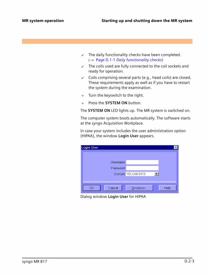
MR system operation Starting up and shutting down the MR system
✓ The daily functionality checks have been completed. (→ Page D.1-1 Daily functionality checks)
✓ The coils used are fully connected to the coil sockets and ready for operation.
✓ Coils comprising several parts (e.g., head coils) are closed. These requirements apply as well as if you have to restart the system during the examination.
✧ Turn the keyswitch to the right.
✧ Press the SYSTEM ON button.
The SYSTEM ON LED lights up. The MR system is switched on. D.2
The computer system boots automatically. The software starts at the syngo Acquisition Workplace. D.2
In case your system includes the user administration option (HIPAA), the window Login User appears. D.2
D.2
Dialog window Login User for HIPAA (3)
0.0
syngo MR B17 0.0D.2-30.0

Starting up and shutting down the MR system MR system operation
✧ If you have installed the user administration option (HIPAA), log in using your user name and Password.
The following is shown on the screen of the syngo Acquisition Workplace: D.2
D.2
Screen display of the syngo Acquisition Workplace (4)
0.0
0.0D.2-4 MAGNETOM Trio a Tim System - MR System0.0

MR system operation Starting up and shutting down the MR system
Switching on the syngo MR Workplace D.2
Since the syngo MR Workplace has its own voltage supply, it is switched on separately from the syngo Acquisition Workplace. D.2
✧ Press the Power On switch at the computer of the syngo MR Workplace.
The software of the syngo MR Workplace starts. D.2
In case your system includes the user administration option (HIPAA), the window Login User appears. D.2
D.2
Dialog window Login User for HIPAA (5)
✧ If you have installed the user administration option (HIPAA), log in using your user name and Password.
0.0
syngo MR B17 0.0D.2-50.0

Starting up and shutting down the MR system MR system operation
The following is shown on the screen of the syngo MR Work-place: D.2
D.2
Screen display at the syngo MR Workplace (6)
B ���After switching on the syngo Acquisition Workplace and the syngo MR Workplace, the system requires approx. 12 minutes to warm up and get ready for acquisition. D.2
0.0
0.0D.2-6 MAGNETOM Trio a Tim System - MR System0.0

MR system operation Starting up and shutting down the MR system
Checking the MR system components D.2
✧ If a dialog window is displayed at the syngo Acquisition Workplace informing you that the helium fill level is too low: Close the window and notify Siemens Service or have the magnet refilled.
✧ Check the Table Stop buttons at the intercom and the con-trol units (to the right and left side of the patient table at the magnet). Move the patient table and press one of the Table Stop buttons. The patient table has to come to a complete stop. Check all three Table Stop buttons one after the other.
✧ Check if pressing the squeeze bulb triggers the patient alert.
✧ Check if communication with the patient in the examina-tion room works properly.
✧ Check if image transmission of the video systems works properly.
✧ Check if the contact spring connectors at the door frame and the door to the examination room are free of residues, such as cleaning agents, oil, grease, paint splatters, blood drops, etc.
0.0
syngo MR B17 0.0D.2-70.0

Starting up and shutting down the MR system MR system operation
Shutting down the system (System Off) D.2
Shutting down the system includes the following steps: D.2
❏ Moving the table into the Home position
❏ Shutting down the computer system
❏ Switching off the MR system at the alarm box
When bringing down the system, the software of the syngo MR Workplace is automatically ended as well. D.2
B ���To avoid possible data losses at the syngo MR Workplace shut down the syngo MR Workplace before the syngo Acquisition Workplace. D.2
B ���If the user is logged on, the system has to be shut down using System > Control... or System > End Session. Otherwise, data are lost. D.2
Moving the table into the Home position D.2
✓ No examinations are in progress.
D.2
✧ Press the Home Position button on the control unit.
The tabletop moves completely out of the magnet. D.2
0.0
0.0D.2-8 MAGNETOM Trio a Tim System - MR System0.0

MR system operation Starting up and shutting down the MR system
Shutting down the compu-ter system D.2
✧ Select System > End Session at the syngo Acquisition Workplace.
The End Session dialog window is displayed. D.2
D.2
End Session dialog window (standard configuration) (7)
0.0
syngo MR B17 0.0D.2-90.0

Starting up and shutting down the MR system MR system operation
D.2
End Session dialog window (HIPAA) (8)
✧ Select the Shutdown System option.
0.0
0.0D.2-10 MAGNETOM Trio a Tim System - MR System0.0

MR system operation Starting up and shutting down the MR system
✧ Click OK.
The following message appears at the syngo Acquisition Work-place: D.2
D.2
Message at the syngo Acquisition Workplace (9)
The following message appears at the syngo MR Workplace. D.2
D.2
Message at the syngo MR Workplace (10)
✧ Switch off the syngo Acquisition Workplace.
✧ Switch off the syngo MR Workplace.
0.0
syngo MR B17 0.0D.2-110.0

Starting up and shutting down the MR system MR system operation
f B ���The software does not respond? D.2
✧ Simultaneously press the Ctrl, Alt, and S keys on the key-board.
The syngo MR System Manager opens. D.2
✧ Shut down the software properly.D.2
f B ���The System Manager cannot be opened? D.2
You can shut down the syngo Acquisition Workplace via the Windows platform. D.2
B ���Please note that this may cause data loss. D.2
✧ Simultaneously press the Ctrl, Alt, and Del keys on the key-board.
The Windows Security window is displayed. D.2
✧ Click the Shut Down button.
The computer shuts down. D.2
D.2
0.0
0.0D.2-12 MAGNETOM Trio a Tim System - MR System0.0

MR system operation Starting up and shutting down the MR system
f B ���System Manager and Windows do not respond? D.2
If the System Manager cannot be started and Windows does not respond, your only option is to switch off the syngo Acquisition Workplace. D.2
B ���Please note that this may cause data loss. D.2
✧ Switch off the syngo Acquisition Workplace.D.2
Switching off the MR system at the alarm box D.2
✓ The computer system has been shut down.
✧ Press SYSTEM OFF.
The MR system is switched off. D.2
✧ Turn the keyswitch to the left.
The MR system is locked. D.2
0.0
syngo MR B17 0.0D.2-130.0

Starting up and shutting down the MR system MR system operation
Shutting down the syngo MR Work-place separately from the syngo Acquisition Workplace D.2
In the System On mode, you are able to just shut down the syngo MR Workplace without affecting the remaining MR sys-tem components. D.2
i ���When the syngo MR Workplace is in operation and the system is ended via the syngo Acquisition Workplace, a message appears on the screen of the syngo MR Workplace. D.2
D.2
Message at the syngo MR Workplace (11)
0.0
0.0D.2-14 MAGNETOM Trio a Tim System - MR System0.0

MR system operation Starting up and shutting down the MR system
Shutting down syngo MR Workplace D.2
✧ Save your data.
✧ At the syngo MR Workplace select System > End session.
The End Session dialog window is displayed. D.2
D.2
End Session dialog window (standard configuration) (12)
0.0
syngo MR B17 0.0D.2-150.0

Starting up and shutting down the MR system MR system operation
D.2
End Session dialog window (HIPAA) (13)
✧ Select the Shutdown System... option.
✧ Click OK.
0.0
0.0D.2-16 MAGNETOM Trio a Tim System - MR System0.0

MR system operation Starting up and shutting down the MR system
The following message appears at the syngo MR Workplace: D.2
D.2
Message at the syngo Acquisition Workplace (14)
✧ Switch off the syngo MR Workplace.
f B ���The software does not respond? D.2
✧ Simultaneously press the Ctrl, Alt, and S keys on the key-board.
The syngo MR System Manager opens. D.2
✧ Shut down the software properly.D.2
f B ���The System Manager cannot be opened? D.2
You can shut down the syngo MR Workplace via the Windows platform. D.2
B ���Please note that this may cause data loss. D.2
0.0
syngo MR B17 0.0D.2-170.0

Starting up and shutting down the MR system MR system operation
✧ Simultaneously press the Ctrl, Alt, and Del keys on the key-board.
The Windows Security window is displayed. D.2
✧ Click the Shut Down button.
The computer is shut down. D.2
D.2
f B ���System Manager and Windows do not respond? D.2
If the System Manager cannot be started and Windows does not respond, your only option is to switch off the syngo MR Work-place. D.2
B ���Please note that this may cause data loss. D.2
✧ Switch off the syngo MR Workplace.D.2
0.0
0.0D.2-18 MAGNETOM Trio a Tim System - MR System0.0

MR system operation Starting up and shutting down the MR system
Starting/ending Host Standby D.2
Host Standby can be started from System On as well as System Off. From Host Standby you can switch the MR system to System On or switch it off completely. D.2
i ���You can also use the syngo MR System Manager to switch between Host Standby and System On (→ Software operator manual). D.2
Starting Host Standby D.2
Starting Host Standby from System Off D.2
✓ The system is in the System Off operating status.
✧ Turn the keyswitch at the alarm box to the right.
The MR system is unlocked. D.2
✧ Press SYSTEM STANDBY.
The host computer is booting up. D.2
0.0
syngo MR B17 0.0D.2-190.0

Starting up and shutting down the MR system MR system operation
Starting Host Standby from System On D.2
✓ The system is in the System On operating status.
✧ Press SYSTEM STANDBY at the alarm box.
All components except for the host computer are switched off. D.2
The SYSTEM ON LED goes off. D.2
Ending Host Standby D.2
Ending Host Standby and switch to System On D.2
✓ The system is in the Host Standby operating status.
✧ Press SYSTEM ON at the alarm box.
The measurement-related components of the MR system are started. D.2
The SYSTEM ON LED lights up. D.2
Ending Host Standby and switch off the MR system D.2
✓ The computer system has been shut down.
✧ Press SYSTEM OFF at the alarm box.
The MR system is switched off. D.2
✧ Turn the keyswitch at the alarm box to the left.
The MR system is locked. D.2
0.0
0.0D.2-20 MAGNETOM Trio a Tim System - MR System0.0

CHAPTER D.2 P
D.3syngo MR B17
reparing the MR system
The following steps are required to prepare the MR system for the patient: D.3
❏ Connecting the squeeze bulb and the headset
❏ Setting the volume for the music and both tunnel lighting and ventilation
i ���The holder for infusion bottles can be attached to the magnet cover to the left above the patient table. D.3
Connecting the squeeze bulb and the headset D.3
D.3
(1) Connection for headphones
(2) Connection for squeeze bulb
✧ Connect the hose connector of the squeeze bulb to the red connector at the foot end of the patient table.
✧ Connect the headset to the connection in yellow at the foot end of the patient table.
0.0
0.0D.3-10.0

Preparing the MR system MR system operation
Set the volume for the music, the tunnel lighting and the ventilation D.3
Use the switches at the control unit to set the music volume for the headset and the wall loudspeaker, the tunnel ventilation as well as tunnel lighting. D.3
D.3
(1) Toggle switch Room - music volume(2) Toggle switch Headphones - music volume(3) Toggle switch Tunnel ventilation(4) Toggle switch Tunnel lighting
0.0
0.0D.3-2 MAGNETOM Trio a Tim System - MR System0.0

MR system operation Preparing the MR system
By pressing the + or– symbol of the respective switch, the func-tion is either increased or decreased by one level. All switches have an auto repeat function, that is, if you press a switch for longer than one second, the function of the switch is automati-cally repeated. D.3
When pressing + or - on the switch, the table display shows the current level selected in the form of a bar in the text output line. The length of the bar indicates the particular level. The display in the text output line disappears within seconds. D.3
B ���The setting of the music volume has no effect on the voice vol-ume of patient announcements. D.3
The tunnel ventilation can be set to the following four levels: D.3
❏ Off
❏ Lowest level
❏ Medium level
❏ Highest level
0.0
syngo MR B17 0.0D.3-30.0

Preparing the MR system MR system operation
0.0
0.0D.3-4 MAGNETOM Trio a Tim System - MR System0.0

CHAPTER D.3 P
D.4syngo MR B17
reparing the patient D.4
D.4
Informing the patient D.4 ✧ Please note the safety instructions.
✧ Inform the patient about the possible effects of MR exami-nations and the risks associated with the magnetic field.
✧ Show the patient how to activate the patient alert by press-ing the squeeze bulb.
✧ Ensure that the patient holds the squeeze bulb in his/her hand during the measurement.
D.4
WARNING D.4
Heat development during the MR examination! D.4
Patient burns D.4
✧ Instruct patients to press the squeeze bulb in case of strong heat sensations.
D.4
WARNING D.4
Use of unapproved fMRI stimulation devices for low and medium field systems (0.2 – 1.5 T)! D.4
Injury to patient and operating personnel D.4
✧ Ensure that the stimulation devices are approved for 3 Tesla systems.
0.0
0.0D.4-10.0

Preparing the patient MR system operation
0.0
0.0D.4-2 MAGNETOM Trio a Tim System - MR System0.0

CHAPTER D.4 P
D.5syngo MR B17
hysiological effects
Due to the presence of alternating electromagnetic fields, patients may experience various physiological effects during MR examinations: D.5
❏ Peripheral nerve stimulation through low-frequency fields of the gradient coils
❏ Warming of body tissue through RF fields of the RF trans-mitter coil
Operating modes D.5
To prevent health risks during MR examinations, several interna-tional organizations (e.g., IEC 60601-2-33 of 2002 (2nd edi-tion)) and various national health organizations have published guidelines and limit values. In compliance with country-specific approval guidelines, they are the basis for the monitoring func-tions integrated in the MR system with respect to stimulation and warming effects. Both stimulation and SAR levels are based on current scientific literature related to safety. D.5
Two different operating modes are available depending on the patient’s tolerance: D.5
❏ Normal Operating Mode
❏ First Level Controlled Operating Mode
With respect to stimulation and warming effects, the operating modes can be defined and selected separately. D.5
0.0
0.0D.5-10.0

Physiological effects MR system operation
Normal Operating Mode D.5
The Normal Operating Mode can be used safely for all patients. D.5
First Level Controlled Operating Mode D.5
D.5
D.5
CAUTION D.5
Exposure to RF electromagnetic fields in the First Level Control-led Operating Mode! D.5
General or local hyperthermia of the patient D.5
✧ Instruct the patient in the use of the squeeze bulb.
✧ Do not examine patients with restricted thermoregulatory capability (e.g. small children, elderly, sick, or medicated patients).
✧ Do not examine patients unable to communicate potential overheating effects (e.g. small children, seriously ill, para-lyzed, unconscious, sedated, or handicapped patients).
✧ Carefully monitor the patient during the MR examination.
✧ Ensure that patients wear light clothing (e.g. light pajamas or nightgown).
✧ Remove all additional insulation, e.g. blankets which could interfere with heat dissipation.
0.0
0.0D.5-2 MAGNETOM Trio a Tim System - MR System0.0

MR system operation Physiological effects
In the First Level Controlled Operating Mode patients may expe-rience noticeable stress levels depending on the measurement programs selected. We recommend establishing a procedure to ensure medical monitoring of the patient. D.5
The decision to change to the First Level Controlled Operating Mode has to be based on a medical consideration of the poten-tial risks and benefits for the patient. D.5
Switching operating modes D.5
D.5
D.5
CAUTION D.5
Tips of screws heat up considerably at the stereotactic frame during the First Level Controlled Operating Mode! D.5
Localized burns of the patient D.5
✧ Please observe the recommendations and notes of the manufacturer of the stereotactic frame.
✧ When the stereotactic frame consists of conductive mate-rial, perform measurements in the Normal Operating Mode only, if possible.
✧ If you still need to switch to the First Level Controlled Oper-ating Mode, please observe the related safety notes.
0.0
syngo MR B17 0.0D.5-30.0

Physiological effects MR system operation
To switch from the Normal Operating Mode to the First Level Controlled Operating Mode, the user has to explicitly select and confirm the change. The request appears in the dialog window of the syngo Acquisition Workplace. In the First Level Controlled Operating Mode, the patient has to be monitored by a physi-cian. D.5
D.5
Dialog window SAR Monitor (15)
0.0
0.0D.5-4 MAGNETOM Trio a Tim System - MR System0.0

MR system operation Physiological effects
Exposure to low frequency electromagnetic fields D.5
Background information D.5
During the measurement, patients are exposed to an electrical field created by the time-varying magnetic fields of the gradi-ents. Assuming all other conditions remain constant, the strength of the electrical field is directly proportional to the change of the magnetic flux (dB/dt). D.5
Peripheral nerve stimulation D.5
Stimulation threshold D.5
The electrical field affects the patient. If the strength of the elec-trical field exceeds a certain threshold (stimulation threshold), the patient experiences peripheral nerve stimulation. Nerve stimulation manifests itself as e.g. tingling sensations or slight muscle spasms in the ribs, side, abdomen, hip, buttock, or tho-racic regions, along the upper arms or the back muscles in the shoulder region. Depending on physiological conditions, the stimulation threshold may vary greatly from patient to patient. D.5
0.0
syngo MR B17 0.0D.5-50.0

Physiological effects MR system operation
Stimulation limits D.5
So-called stimulation limits were determined by averaging the individual stimulation thresholds of test subjects during an extensive clinical trial. Based on the statistical distribution, it can be expected that up to 50 % of all patients will experience at least mild stimulations after reaching this stimulation limit. D.5
Monitoring D.5
The MR system software includes a monitoring feature (stimula-tion monitor) which monitors the stimulation limit. D.5
The information window of the stimulation monitor provides information regarding how close patients are to the stimulation limit during the examination. D.5
Look Ahead monitoring D.5
Prior to starting the MR examination, the stimulation monitor checks whether the stimulation limits may be exceeded. If so, the measurement cannot be started. To perform the examina-tion, the parameters of the measurement sequence have to be adjusted accordingly. D.5
0.0
0.0D.5-6 MAGNETOM Trio a Tim System - MR System0.0

MR system operation Physiological effects
Online monitoring D.5
If the stimulation limit is exceeded while a measurement is in progress, the active measurement is aborted and the gradient currents are reduced. D.5
Operating modes D.5
The MR system can be operated in two operating modes which differ with respect to gradient power limits. D.5
The power limits are based on stimulation models derived from the statistically determined stimulation limits. The possible patient effects are the same regardless of the operating mode. However the higher the gradient output is the higher the prob-ability and the intensity of the effects (e.g. peripheral nerve stimulation). D.5
Stimulation models D.5
The following stimulation models are used: D.5
❏ SAFE model 1 (empirical)
❏ dB/dt model
1 Stimulation Approximation by Filtering and Evaluation
0.0
syngo MR B17 0.0D.5-70.0

Physiological effects MR system operation
The SAFE model is the standard model covered by the new IEC 60601-2-33 (2nd edition). While only country-specific guidelines apply to the dB/dt model, the SAFE model also con-siders the dependency of the stimulation effect on the parame-ters of the measurement sequence (rise time, amplitude, number of axes, repetition rate, etc.). D.5
Normal Operating Mode D.5
During Normal Operating Mode, the limit is set to 80 % of the stimulation limit according to IEC 60601-2-33 (2nd edition). At full performance, the ratio of patients affected by peripheral nerve stimulation is rather low. D.5
First Level Controlled Operating Mode D.5
In the First Level Controlled Operating Mode, the performance limits are determined directly from the statistically determined stimulation limits. Accordingly, at full performance, up to 50 % of all patients may experience mostly mild stimulations; how-ever, a smaller portion may experience significant stimulation. D.5
0.0
0.0D.5-8 MAGNETOM Trio a Tim System - MR System0.0

MR system operation Physiological effects
Exposure to RF electromagnetic fields D.5
Background information D.5
During the course of an MR examination, the patient’s body absorbs energy from the RF field of the transmitter coil. Depend-ing on the type of transmitter coil used, the absorption is either concentrated locally (when using so-called non-volume coils) or relatively uniform across the part of the body examined (when using volume coils, e.g. extremity or body coil). D.5
The Specific Absorption Rate (SAR), expressed as W/kg, serves as a stress indicator. D.5
Unacceptably high local SAR values may lead to RF burns. At high values, the SAR that is exposed evenly across the body adversely affects the patient’s thermoregulation and the cardio-vascular system. D.5
0.0
syngo MR B17 0.0D.5-90.0

Physiological effects MR system operation
Warming of body tissue D.5
The energy absorbed in the course of the MR examination warms the tissue. The heat generated is dissipated by the ther-moregulation mechanisms of the patient, e.g., through increased perspiration and blood flow. D.5
The body temperature increases if the patient absorbs more energy per unit of time than can be dissipated through ther-moregulation. The longer this condition lasts, the greater the increase in temperature. D.5
The increase in core body temperature is usually well below 1 °C during the course of the MR examination (if the SAR limits described below are maintained). D.5
Noticeable effects on the patient D.5
During the MR examination, patients experience heat sensa-tions on the skin and may begin to perspire. Their pulse rate may increase as well. The individual effects vary from patient to patient. The intensity of these effects depends on the measure-ment program selected. As compared to the Normal Operating Mode, measurement programs with considerably higher inten-sities may be used in the First Level Controlled Operating Mode. Following the examination, the body will cool off. The pulse rate will return to normal. D.5
0.0
0.0D.5-10 MAGNETOM Trio a Tim System - MR System0.0

MR system operation Physiological effects
Temperature control inside the examination room D.5
A temperature sensor, located near the air intake for the tunnel ventilation, monitors the room temperature. If the room tem-perature exceeds 24 °C, the SAR values are regulated and low-ered accordingly. As a result, the parameters of certain MR measurement sequences may need to be adjusted. D.5
SAR limits D.5
B ���Considering all possible tolerances, the SAR values are always calculated based on the worst possible value. This ensures that the specific SAR limit is maintained. D.5
Depending on the medical question, different RF coils are applied (e.g. extremity or body coil). The effects on the patient vary, depending on the type of coil used. Taking this factor into consideration, different SAR limits have been established for dif-ferent types of examinations. The software automatically deter-mines the limit to be applied. D.5
0.0
syngo MR B17 0.0D.5-110.0

Physiological effects MR system operation
SAR monitoring D.5
SAR limits are monitored by a software monitoring function. D.5
Look Ahead monitoring D.5
Prior to each measurement, the estimated SAR values are auto-matically calculated and compared with the prescribed limit val-ues, including possible measurement errors. If one of the calcu-lated SAR values exceeds the corresponding limit, the measurement cannot be started. The following message appears in the dialog window of the syngo Acquisition Work-place: SAR Limit(s) Exceeded! D.5
B ���To ensure correct computation of the SAR values, the weight of the patient has to be entered during registration. D.5
0.0
0.0D.5-12 MAGNETOM Trio a Tim System - MR System0.0

MR system operation Physiological effects
D.5
This dialog window includes suggested changes to the exami-nation parameters which allow the examination to continue. In addition, a button in the dialog window may be used to change the operating mode. D.5
B ���In the First Level Controlled Operating Mode, often only minor modifications (if any) may be required. D.5
0.0
syngo MR B17 0.0D.5-130.0

Physiological effects MR system operation
Online monitoring D.5
The system constantly measures the transmit power and ensures that the appropriate limit values are observed. Exami-nations in progress will be aborted if the limit is exceeded. D.5
Limit values D.5
The SAR limits used by the Look Ahead monitoring function are set according to country-specific approval guidelines at the time of the syngo MR installation. D.5
Normal Operating Mode D.5
During Normal Operating Mode, the patient barely notices the effects of the RF field. The stress on the cardio-vascular system is negligible. D.5
0.0
0.0D.5-14 MAGNETOM Trio a Tim System - MR System0.0

MR system operation Physiological effects
First Level Controlled Operating Mode D.5
In the First Level Controlled Operating Mode, patients may experience noticeable stress levels depending on the measure-ment programs selected. This usually includes perspiration accompanied by an increase in pulse rate. Patients with reduced thermoregulatory capability and higher sensitivity toward increases in body temperature (e.g., patients with fevers or car-diac decompression, patients with perspiratory impairments, or pregnant women) may experience additional effects. D.5
Display of SAR values D.5
The current SAR values, encoded according to body regions, can be accessed at any time (→ Software operator manual). D.5
0.0
syngo MR B17 0.0D.5-150.0

Physiological effects MR system operation
0.0
0.0D.5-16 MAGNETOM Trio a Tim System - MR System0.0

CHAPTER D.5 S
D.6 msyngo MR B17
tarting/Stopping the easurement
Starting the measurement D.6 ✓ The measurement protocol is loaded.
✓ No MR measurement is active.
D.6
✧ Press the Start/Stop button on the control unit (→ Page B.4-1 Control unit).
The measurement begins. D.6
The table display is deactivated. D.6
Stopping the measurement D.6 ✓ The MR measurement is active.
D.6
✧ Press the Start/Stop button on the control unit (→ Page B.4-1 Control unit).
The measurement is stopped. D.6
The table display is activated. D.6
0.0
0.0D.6-10.0

Starting/Stopping the measurement MR system operation
0.0
0.0D.6-2 MAGNETOM Trio a Tim System - MR System0.0

PART D.6 M
Esyngo MR B17
aintenance
E.1 Cleaning E.1-1
E.2 Return and disposal E.2-1
MR System E.2-1
Packaging E.2-2
Batteries and accumulators E.2-2
0.0
0.0E-10.0

Maintenance
0.0
0.0E-2 MAGNETOM Trio a Tim System - MR System0.0

CHAPTER E.0 C
E.1syngo MR B17
leaning
Cleaning the LCD monitor/video display E.1
The LCD monitor of the syngo Acquisition Workplace and the video display are cleaned in the same way. E.1
✧ Clean the LCD monitor/video display every two month.
✧ Clean the monitor/video display using a microfiber cloth.
✧ If the LCD monitor/video display can not be effectively cleaned with the microfiber cloth: use window cleaner. Do not use window cleaner on the monitor housing.
✧ Immediately remove water drops on the LCD monitor/video display.
✧ Avoid scratching the surface area of the LCD monitor/video display.
✧ Avoid impacts to the LCD monitor/video display.
B E��The LCD monitor/video display are highly sensitive to mechani-cal damage. E.1
Cleaning the data carrier E.1 ✧ Clean contaminated data carriers with a clean cloth (cotton or microfiber).
✧ Follow the manufacturer's notes when cleaning CD/DVD data carriers.
0.0
0.0E.1-10.0

Cleaning Maintenance
Cleaning the plugs and con-nectors E.1
✧ Dampen a soft cloth with water or a diluted household cleaner solution. Do not use organic solvents, such as alco-hol or acetone.
✧ Carefully wipe the plugs and connectors with the cloth. Do not touch the contacts.
Cleaning RF coils and posi-tioning aids E.1
✧ Clean the RF coils and positioning aids using commercially available cleaning and disinfection solutions. Follow manu-facturer's instructions.
✧ Do not use hard or sharp objects (e.g., knives or tweezers) to remove residue.
B E��Do not pour cleaning fluid on surface areas - always use a damp cloth to clean them. E.1
Cleaning the patient table and the straps E.1
✧ Clean the patient table using a liquid household agent.
✧ Wash the straps of the patient table at a temperature of 60 °C.
✧ Use commercial disinfecting materials. However, do not use solutions with alcohol or acetone.
0.0
0.0E.1-2 MAGNETOM Trio a Tim System - MR System0.0

Maintenance Cleaning
Cleaning and disinfecting the receptors E.1
✧ Do not use cleaners or disinfectants containing alcohol or ether.
✧ Do not use hard or sharp objects (e.g. knives or tweezers) to remove residue.
✧ Clean the receptors with a commercially available cleaner. Follow manufacturer’s instructions.
✧ Use a dampened cloth for cleaning.
B E��Do not submerge the receptors in cleaning liquid. E.1
✧ Disinfect the receptors with a commercially available disin-fecting agent. Follow manufacturer’s instructions.
Disinfecting system compo-nents E.1
B E��Disinfecting sprays damage electronic components. For this rea-son, components may be cleaned with a semi-dry cloth only. E.1
✧ Disinfect the system components with commercial disin-fecting materials. However, do not use solutions with alco-hol. Follow manufacturer’s instructions.
B E��Siemens does not test alcohol-containing, phenol-alkaline and alkaline-based disinfectants for harmful effects on surfaces. Avoid disinfecting system components with these materials. E.1
0.0
syngo MR B17 0.0E.1-30.0

Cleaning Maintenance
Care and cleaning of floors E.1 Do not use the following cleaning or care products: E.1
❏ Sprays
❏ Silicon-based cleaning or care products
❏ Cleaning or care products with substances that release ammonia
❏ Cleaning or care products that destroy the anti-static prop-erties of the floor covering
✧ Use commercially available cleaning or care products for the floor. Follow manufacturer's instructions.
0.0
0.0E.1-4 MAGNETOM Trio a Tim System - MR System0.0

CHAPTER E.1 R
E.2syngo MR B17
eturn and disposal
MR System E.2
E.2
E.2
✧ Contact Siemens Service in case of questions about return-ing and disposing the MR system and/or its components and accessories.
E.2
WARNING E.2
Explosion hazard during improper disassembly! E.2
Injury of persons E.2
✧ Ensure that only trained personnel disassemble the MR sys-tem because the system includes a pressurized container and cryogenic helium.
E.2
WARNING E.2
Unauthorized work on the magnet! E.2
Personal injury, property damage E.2
✧ Only authorized personnel (Siemens Magnet Technology or Siemens) may perform work on the magnet.
✧ Do not open or remove safety valves and burst disks of the helium container.
✧ Do not change the standard configuration.
0.0
0.0E.2-10.0

Return and disposal Maintenance
Packaging E.2
B E��Siemens AG is obligated to accept the return of packaging mate-rial. E.2
✧ Contact Siemens Service regarding questions with respect to the return as well as subsequent disposal of packaging material.
✧ Observe national regulations.
Batteries and accumulators E.2
B E��Siemens AG is obligated to accept the return and disposal of bat-teries and accumulators. E.2
✧ Contact Siemens Service with respect to questions regard-ing the return and disposal of batteries and accumulators.
✧ Observe national regulations.
0.0
0.0E.2-2 MAGNETOM Trio a Tim System - MR System0.0

APPENDIX E.2 I
Fsyngo MR B17
ndex
A F.0
Accessories F.0
Safety instructions A.2-29 F.0
Accidents F.0
Breathing difficulties A.2-39 F.0
Coils A.2-19 F.0
Frostbite A.2-40 F.0
Measurement phantoms A.2-19 F.0
Alarm box F.0
Checks B.6-3 F.0
Description B.6-1 F.0
Functional check B.6-3 F.0
Announcement F.0
Automatic voice output B.7-5 F.0
Live announcement B.7-4 F.0
Artifact A.2-22 F.0
Patient-related A.2-28 F.0
System-related A.2-22 F.0
B F.0
Breathing difficulties A.2-39 F.0
Burns F.0
Frostbite A.2-40 F.0
C F.0
Checks F.0
Alarm box B.6-3 F.0
Daily functionality checks D.1-1 F.0
Cleaning F.0
Connections E.1-2 F.0
Floor E.1-4 F.0
Monitor/video screen E.1-1 F.0
MR system E.1-1 F.0
Patient table E.1-2 F.0
Positioning aids E.1-2 F.0
Receptors E.1-3 F.0
RF Coils E.1-2 F.0
Straps of the patient table E.1-2 F.0
Coils F.0
Accidents A.2-19 F.0
Combination F.0
With other devices and accessories A.2-16 F.0
Compatibility F.0
Safety information A.2-16 F.0
Computer system F.0
Shutting down D.2-8 F.0
Start D.2-2 F.0
0.0
0.0F-10.0
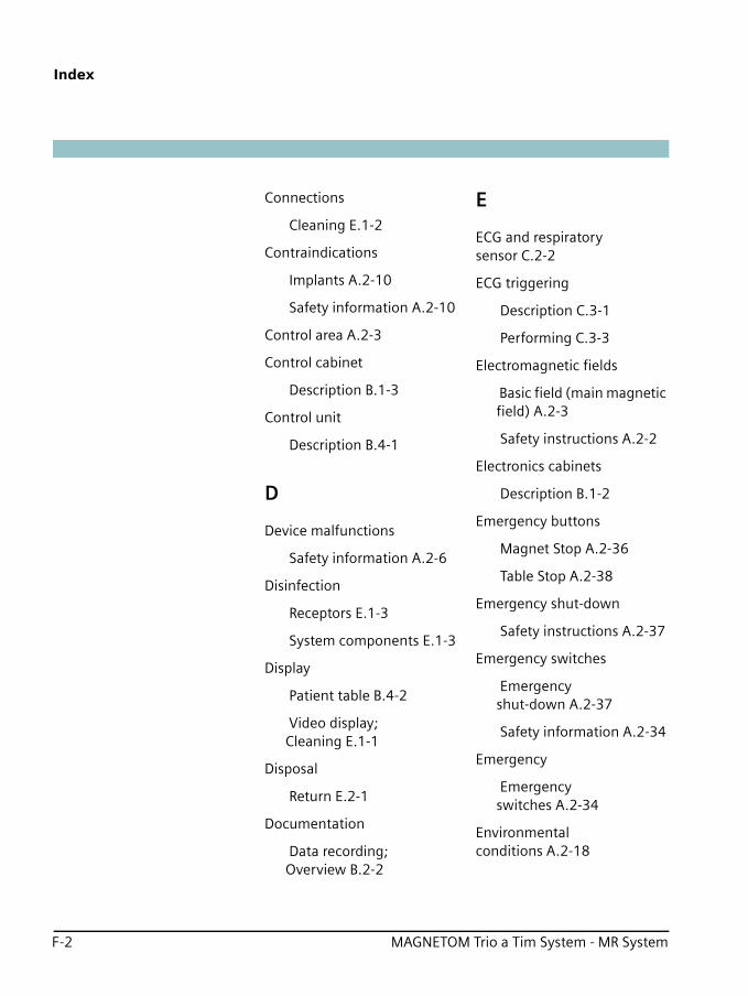
Index
Connections F.0
Cleaning E.1-2 F.0
Contraindications F.0
Implants A.2-10 F.0
Safety information A.2-10 F.0
Control area A.2-3 F.0
Control cabinet F.0
Description B.1-3 F.0
Control unit F.0
Description B.4-1 F.0
D F.0
Device malfunctions F.0
Safety information A.2-6 F.0
Disinfection F.0
Receptors E.1-3 F.0
System components E.1-3 F.0
Display F.0
Patient table B.4-2 F.0
Video display; Cleaning E.1-1 F.0
Disposal F.0
Return E.2-1 F.0
Documentation F.0
Data recording; Overview B.2-2 F.0
E F.0
ECG and respiratory sensor C.2-2 F.0
ECG triggering F.0
Description C.3-1 F.0
Performing C.3-3 F.0
Electromagnetic fields F.0
Basic field (main magnetic field) A.2-3 F.0
Safety instructions A.2-2 F.0
Electronics cabinets F.0
Description B.1-2 F.0
Emergency buttons F.0
Magnet Stop A.2-36 F.0
Table Stop A.2-38 F.0
Emergency shut-down F.0
Safety instructions A.2-37 F.0
Emergency switches F.0
Emergency shut-down A.2-37 F.0
Safety information A.2-34 F.0
Emergency F.0
Emergency switches A.2-34 F.0
Environmental conditions A.2-18 F.0
0.0
0.0F-2 MAGNETOM Trio a Tim System - MR System0.0

Index
Examination F.0
Preparation; MR system D.3-1 F.0
External triggering F.0
Description C.6-1 F.0
Performing C.6-2 F.0
F F.0
Failures F.0
Safety instructions A.2-29 F.0
Fire F.0
Safety instructions A.2-40 F.0
Foot switch F.0
Operation B.3-5 F.0
Full operation F.0
MR system operating modes D.2-1 F.0
Functional check F.0
Alarm box B.6-3 F.0
Daily D.1-1 F.0
G F.0
Gradient cabinet F.0
Description B.1-2 F.0
H F.0
Hazard hints F.0
Configuration A.1-2 F.0
Verbal signals A.1-2 F.0
Hazards F.0
Common sources of danger A.2-1 F.0
Contraindications A.2-10 F.0
Electromagnetic fields A.2-2 F.0
Mechanical hazards A.2-13 F.0
Noise development A.2-19 F.0
Potential hazards A.2-1 F.0
RF and gradient fields A.2-7 F.0
Static magnetic field A.2-4F.0
Headset F.0
Connect D.3-1 F.0
Host standby F.0
MR system operating modes D.2-1 F.0
0.0
syngo MR B17 0.0F-30.0

Index
I F.0
Imaging errors A.2-22 F.0
Implants F.0
Device malfunctions A.2-6F.0
In-Room syngo Acq WP F.0
Description B.3-1 F.0
Operation B.3-2 F.0
Intercom F.0
Description B.7-1 F.0
Operation B.7-3 F.0
L F.0
Laser light localizer F.0
Description B.5-1 F.0
Listening to the patient F.0
Transmitting announce-ments made by the patient B.7-4 F.0
Look Ahead monitoring F.0
Low-frequency fields D.5-6 F.0
SAR monitoring D.5-12 F.0
M F.0
Magnet Stop F.0
Safety information A.2-36 F.0
Magnetic field F.0
Physiological effects; Low frequency fields D.5-5 F.0
Physiological effects; RF fields D.5-9 F.0
Maintenance F.0
MR system E.1-1 F.0
Safety information A.2-29 F.0
Measurement phantoms F.0
Accidents A.2-19 F.0
Measurement F.0
Start/Stop D.6-1 F.0
Starting and ending; with footswitch B.3-5 F.0
Terminating; Intercom B.7-8 F.0
Mechanical hazards F.0
Safety instructions A.2-13 F.0
Monitor F.0
Cleaning E.1-1 F.0
In-Room syngo Acq WP B.3-2 F.0
Monitoring F.0
Intercom; Description B.7-1 F.0
Intercom; operation of B.7-3 F.0
Look Ahead monitoring D.5-6 F.0
0.0
0.0F-4 MAGNETOM Trio a Tim System - MR System0.0

Index
Online monitoring D.5-7 F.0
SAR monitoring D.5-12 F.0
MR compatibility A.2-16 F.0
MR system F.0
Operating modes D.2-1 F.0
Shutting down the system D.2-8 F.0
Starting the syngo MR WP D.2-5 F.0
Starting the system D.2-2 F.0
Starting/ending Host Standby D.2-19 F.0
Switching on/off D.2-1 F.0
syngo MR WP shut down D.2-14 F.0
Music F.0
Playing B.7-6 F.0
N F.0
Nerve stimulation F.0
Low-frequency fields D.5-5 F.0
Noise development F.0
Safety information A.2-19 F.0
O F.0
Online monitoring F.0
Low-frequency fields D.5-7 F.0
SAR monitoring D.5-14 F.0
Operating consoles F.0
In-Room syngo Acq WP B.3-2 F.0
In-Room syngo Acq WP Description B.3-1 F.0
Starting the syngo MR WP D.2-5 F.0
syngo MR WP shut down D.2-14 F.0
Operating mode F.0
First Level Controlled Operating Mode D.5-2 F.0
MR system D.2-1 F.0
Normal Operating Mode D.5-2 F.0
Performance limits; low-frequency fields D.5-7 F.0
Switching D.5-3 F.0
0.0
syngo MR B17 0.0F-50.0

Index
P F.0
Patient alert F.0
Acknowledgement B.7-9 F.0
Safety information B.7-3 F.0
Patient care F.0
Patient instructions A.2-20 F.0
Patient monitoring A.2-20 F.0
Patient monitoring F.0
Intercom; Description B.7-1 F.0
Intercom; operation of B.7-3 F.0
Patient table F.0
Cleaning E.1-2 F.0
Description B.8-1 F.0
Displays B.4-2 F.0
Operation B.8-4 F.0
Physiological effects F.0
Description D.5-1 F.0
First Level Controlled Operating Mode D.5-2 F.0
Low frequency fields D.5-5F.0
Monitoring; low-fre-quency fields D.5-6 F.0
Normal Operating Mode D.5-2 F.0
Operating modes D.5-1 F.0
RF fields D.5-9 F.0
SAR limit values D.5-11 F.0
SAR monitoring D.5-12 F.0
Switching between oper-ating modes D.5-3 F.0
Warming of body tissue D.5-10 F.0
Physiological Measurement Unit F.0
Description C.2-1 F.0
Dialog window C.2-6 F.0
ECG and respiratory sensor C.2-2 F.0
External trigger input/output C.2-5 F.0
Operation C.2-9 F.0
PMU display C.2-5 F.0
Pulse sensor C.2-4 F.0
Preparation F.0
MR system D.3-1 F.0
Patient; For MR examination D.4-1 F.0
Pulse sensor C.2-4 F.0
Pulse triggering F.0
Description C.4-1 F.0
Performing C.4-2 F.0
0.0
0.0F-6 MAGNETOM Trio a Tim System - MR System0.0

Index
Q F.0
Quality Assurance F.0
Coils A.2-19 F.0
R F.0
Repair F.0
Safety information A.2-29 F.0
Respiratory triggering F.0
Description C.5-1 F.0
Performing C.5-2 F.0
Responsibility F.0
Safety guidelines A.1-1 F.0
RF and gradient fields F.0
Safety instructions A.2-7 F.0
RF coils F.0
Description B.1-4 F.0
RF power amplifier F.0
Description B.1-3 F.0
S F.0
Safety guidelines F.0
MR safety A.2-1 F.0
Responsibility A.1-1 F.0
Safety information F.0
Contraindications A.2-10 F.0
Emergency switches A.2-34 F.0
Maintenance/repair A.2-29 F.0
Patient alert B.7-3 F.0
Preface A.1-1 F.0
SAR F.0
Limit values; Safety information D.5-11 F.0
Limits, high-frequency fields D.5-11 F.0
Monitoring D.5-12 F.0
Signs and symbols F.0
Warning and prohibition signs A.2-30 F.0
Squeeze bulb F.0
Connect D.3-1 F.0
Standby mode F.0
MR system operating modes D.2-1 F.0
Static magnetic field F.0
Device malfunctions A.2-6F.0
Safety instructions A.2-4 F.0
Super-conducting magnet F.0
Description B.1-1 F.0
syngo Acquisition Workplace F.0
Description B.2-1 F.0
0.0
syngo MR B17 0.0F-70.0

Index
syngo MR WP F.0
Shutting down D.2-14 F.0
Start D.2-5 F.0
T F.0
Table Stop F.0
Safety information A.2-38 F.0
Temperature control F.0
Safety guidelines D.5-11 F.0
Triggering methods F.0
Overview C.1-1 F.0
V F.0
Video display F.0
Cleaning E.1-1 F.0
Volume F.0
Automatic voice output B.7-5 F.0
Live announcement B.7-4 F.0
Music B.7-6 F.0
Volume for listening to the patient B.7-4 F.0
W F.0
Warming F.0
Radio frequency fields D.5-10 F.0
Warning labels F.0
Warning and prohibition signs A.2-30 F.0
0.0
0.0F-8 MAGNETOM Trio a Tim System - MR System0.0

F.0

© Siemens AG 2005-2009Order No.M6-03001.621.04.01.02Printed in Germany05/2009
Siemens AG Wittelsbacherplatz 2D-80333 MünchenGermany
CSHHDGTw
www.siemens.com/healthcare
ontact addressiemens AGealthcare Sectorenkestr. 127-91052 Erlangenermanyelephone: +49 9131 840ww.siemens.com/healthcare