summary - iabse forensics/alonso 2014.pdf · fig 2 visible crack patterns in foundations. 4. finite...
TRANSCRIPT
Tomás RIPA ALONSO Partner. Civil Engineer LRA Infrastructures Consulting Madrid, SPAIN [email protected] Tomás Ripa received his civil engineering degree from the Technical University of Madrid, Spain. Apart from managing LRA Infrastructures Consulting, T.Ripa is Senior Lecturer at Technical University of Madrid.
Enrique GONZÁLEZ DUEÑAS Civil Engineer LRA Infrastructures Consulting Madrid, SPAIN [email protected] Enrique González received his civil engineering degree from Technical University of Madrid with a year abroad at Imperial College London. Soon after graduation, E. González joined the structures department at LRA Infrastructures Consulting.
Summary Wind turbine foundations are load extremely eccentrically and the loading is usually highly dynamic. Over the last years, an observable fact is arising in some wind farms: a set of discrete and clearly visible radial and circumferential cracks appear at regular intervals around the embedded steel tower. Fortunately, if these cracks are detected at an early stage they do not reduce the structural integrity of the foundation. However, if water makes its way through the cracks it can reach the reinforcement, which in addition to dynamic loads and fatigue, can make the matters worse and compromise the serviceability of the structure.
Based on the crack patterns recorded in the field and with the aid of a simulated finite element model using contact elements, the origin and nature of the cracks were identified. Furthermore, stresses in the foundation have been obtained in order to be controlled. These stresses do not exceed the ultimate strength of concrete but cracks finally appear due to cycle loading.
In this paper, the structural behaviour of the foundation is analyzed based on the cracks observed at the site and interpreting a FE model.
Keywords: Wind turbines, foundation, cracks, finite elements, repair, forensic engineering.
1. Introduction The element designed for resisting the loads of a wind turbine and carrying them to the soil is the wind turbine foundation. Wind turbines transmit to the base a reduced vertical force, an horizontal load that is not relevant and an extreme bending moment. Apart from wind farms access roads, foundations represent the main civil engineering activity when erecting a wind farm.
Damages in the foundations are found when maintaining specific kinds of foundations in certain wind turbine farms. Due to their frequent presence, damages analysed in this document are those that occur mainly in wind turbines with an embedded steel ring inserted in the foundation. The damages appear as radial and circumferential cracks in the pedestal, near the steel tower mast.
Due to dynamic nature of loading, these cracks are not static. They grow as the number of load cycles increase and fatigue alters concrete properties. Depending on the structural mechanism of the foundation, these cracks may affect the integrity of the structure in different ways. Although cracks will not cause structure to collapse, they will create gaps in the concrete and originate oscillations in the steel tower, requiring very expensive repairs.
This paper summarises all possible types of foundations in wind turbine designs. After that, cracks are shown to illustrate the pathology. Finally, structural origin of these cracks is analysed with the aid of a Finite Element program.
2. Types of foundations There is not a unique foundation for onshore wind turbines. The size, shape and type of foundation
selected for each project depends on three aspects: Wind turbine loads, type of tower (concrete,
steel, hybrid...) and Geotechnical conditions of the soil. Considering these elements, foundation
types can be classified as follows.
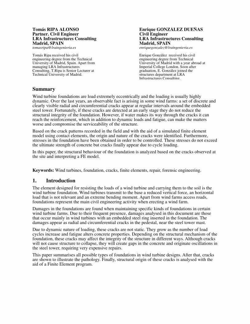
Spread foundation
When the stratum is stable, has good consistency and is stiff enough, loads can be transferred
directly on the surface. A concrete spread foundation it then generally used to transfer the loads.
Fig 1 Spread foundation.
Deep foundation
If the upper layers of the soil are not stiff enough or do not resist high pressures, loads must be
transferred to a deep layer. This type of foundation it is also used when the soil is unstable or
altered by any mean (karst, liquefaction, etc…).
Combined foundation
Between the last two types, the so called mixed or combined foundation is used in compact or hard
soils that are not stiff enough for a spread foundation.
This paper focuses on spread foundation on account of the fact that this is the most common type of
foundation used. However, the analysis can be easily extrapolated to deep or combined foundations.
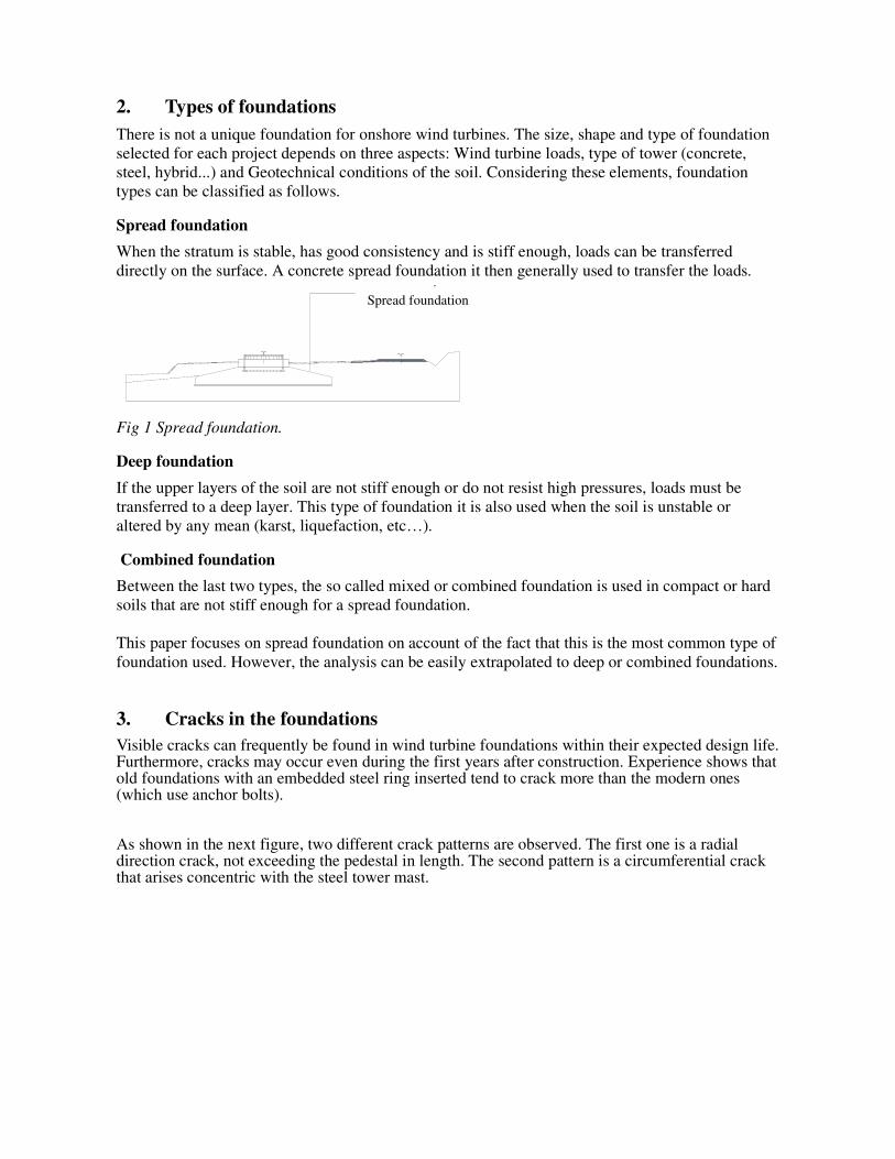
3. Cracks in the foundations Visible cracks can frequently be found in wind turbine foundations within their expected design life. Furthermore, cracks may occur even during the first years after construction. Experience shows that old foundations with an embedded steel ring inserted tend to crack more than the modern ones (which use anchor bolts).
As shown in the next figure, two different crack patterns are observed. The first one is a radial direction crack, not exceeding the pedestal in length. The second pattern is a circumferential crack that arises concentric with the steel tower mast.
CIMENTACIÓN DIRECTASpread foundation

Fig 2 Visible crack patterns in foundations.
4. Finite Element analysis After showing which type of visible cracks is frequently found in wind turbine foundations, a complete load path analysis is performed. This will justify the origin and nature of observed cracks. Cracks structural analysis depends on the operational conditions of the turbine, geometry of the foundation and geotechnical parameters of the soil. With these conditions, a wind turbine foundation located in the north of Spain is analyzed. The diameter of the foundation is 17,50 m. The geometry is depicted in the next figure.
Fig 3 Diametric section of the foundation.
The Finite Element model of the foundation is achieved with the aid of a FE software, ANSYS. Between the element types provided by the software, solid finite elements have been used. These elements are then set with concrete properties (C30/37) and structural steel for the insert ring (Young modulus 210.000 MPa). The interface between these two must behave as a contact surface. This issue configures the model as a high non-linear problem to be solved.
In the next figure, the foundation model is shown. From the picture, it can be seen the difference between the materials used, represented in different colors. The contact elements are not visible given that they are inserted in the interface steel-concrete.
Fig 4 3D view of the wind turbine foundation FE Model.
IEC-61400 [1] has been used to determine the loads (characteristic and design loads) and to study all possible load cases. Different editions of the guidelines for designing wind turbines from Germanischer Lloyd ([2] and [3]) have been used as well. Spain´s adoptions of international rules and local annex [4] have been considered when modeling the loads. After considering all possible load cases and design situations stated in reference [4], maximum loads at support are as follows.
After applying loads to the model, the non-linear analysis is performed. Once results are obtained, one can analyze how different stresses in the model solution reflect real load transmission from the steel insert ring embedded in the concrete.
First of all, it is observed (see figure 5) that the bending moment applied is mainly resisted by a pair (compression-traction) located in the inner flange of the steel insert ring. If the stresses at this point are integrated through the circumference, one can conclude that 80% of the bending moment relies on this mechanism. The remaining 20% must be resisted, then, by the upper pedestal.
Secondly, with the precision obtained, the total vertical force can be easily calculated by means of the contact surfaces in the inferior flange. Taking into account both superior and inferior contact elements surrounding the flange, the total vertical force at this level is 3.209 kN. Hence, 8% of the vertical load is transferred as friction in the mast embedded in concrete.
Table 1: Maximum wind turbine loads (at support).
Load Vertical force
[kN]
Bending
Moment
[mkN]
Max. -3.510,0 63.825,0

Fig 5 Vertical stresses in the foundation [kN/m2].
A global cylindrical coordinate system is now used to better understand the stresses. Given that the main patterns of the cracks are radial and circumferential; this is a proper coordinate system to analyze the results. From now on, only the upper part of the foundation (including pedestal) will be showed.
Figure 6 shows radial stresses in the pedestal. Blue and green areas represent compressions, which are within the concrete range admissibility. These are the main points of contact between the tower and the foundation (pedestal).
Fig 6 Radial stresses in the pedestal [kN/m2].
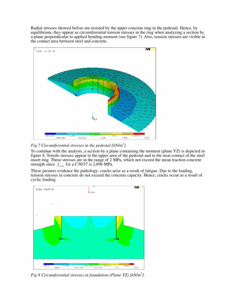
Radial stresses showed before are resisted by the upper concrete ring in the pedestal. Hence, by equilibrium, they appear as circumferential tension stresses in the ring when analyzing a section by a plane perpendicular to applied bending moment (see figure 7). Also, tension stresses are visible at the contact area between steel and concrete.
Fig 7 Circumferential stresses in the pedestal [kN/m2].
To continue with the analysis, a section by a plane containing the moment (plane YZ) is depicted in figure 8. Tensile stresses appear in the upper area of the pedestal and in the near-contact of the steel insert ring. These stresses are in the range of 2 MPa, which not exceed the mean traction concrete strength since ,ct m
f for a C30/37 is 2,896 MPa.
These pictures evidence the pathology: cracks arise as a result of fatigue. Due to the loading, tension stresses in concrete do not exceed the concrete capacity. Hence, cracks occur as a result of cyclic loading.
Fig 8 Circumferential stresses in foundation (Plane YZ) [kN/m2].

5. Conclusions This paper analyzes the origin and nature of cracks in onshore wind turbines. As evidenced in the text, cracks are originated by the dynamic tensile stresses that occur in the pedestal due to cyclic loading and fatigue in concrete. As the load continues, the crack length increases.
The analysis has been performed with the aid of a Finite Element software, starting point to understanding the certain problem and planning for best solutions.
6. References [1] IEC 61400-1. “Wind Turbines – Part 1: Design requirements”. Third edition. 2005-2008.
[2] “Guideline for the Certification of Wind Turbines”. Germanichser Lloyd, 2003.
[3] “Guideline for the Certification of Wind Turbines”. Germanischer Lloyd, 2010.
[4] UNE-EN61400-1:2005/A 1:2010. “Aerogeneradores Parte 1: Requisitos de seguridad”. 2005.