sugar industry technologists meeting - sugar process modeling
TRANSCRIPT

SUGAR INDUSTRY
TECHNOLOGISTS MEETING
May 9-12, 1999
Estoril, Portugal
S.I.T. Paper # 751
AL KHALEEJ SUGAR AN ENERGY EFFICIENT REFINERY.
By
Jamal Al Ghurair & G.C. Singh
AL KHALEEJ SUGAR DUBAI
UNITED ARAB EMIRATES

2
ABSTRACT: Recently a number of stand-alone refineries have been constructed close to their final markets in several locations around the world. The Al Khaleej Sugar (AKS) refinery, located at the Jebel Ali port in Dubai, United Arab Emirates, was the first refinery to operate in the Middle East/ Gulf market. Designed in 1992-94, and commissioned in 1995, the refinery has been operating at its design capacity of 100 tonnes melt/hour since Nov’ 1997. The refinery uses a conventional refining process, including carbonation and granular carbon decolourisation, but also has several innovative plant applications, including the use of continuous vertical pans for all white massecuite, and vapour bleeding from evaporators for pan heating. Important design goals for the refinery included: ♦ The ability to produce high quality refined sugar from the various types and
qualities of raw sugar available on the world market. ♦ Selection of an established process technology for which technical support, skilled
operators, and process chemicals would be readily available. ♦ A modern process control concept, based on a distributed control system, with few
operators and high labour productivity. ♦ Compliance with environmental requirements, particularly in terms of avoiding
sugar loss to the harbour through cooling water or condensates. Finally, because of the high costs of fuel oil, electricity, and water, there was an overriding requirement that the refinery would be more energy efficient than established refineries, which operated at usage levels of about 3500 MJ/tonne melt. These goals have been largely achieved, with refinery energy consumption while melting high purity raw sugar typically:
Boiler fuel 2185 MJ/tonne melt Carbon kiln fuel 30 Purchased Power 235 Total Energy used 2450 MJ/tonne melt.
This paper reviews the plant and process arrangements installed to achieve these results. 1. INTRODUCTION The design of a refinery is mainly based on local conditions and each case must be considered individually. For AKS, besides the cost of primary energy; i.e., fuel and electricity, water is also important. In the gulf region, fuel is available at international prices, Electricity is purchased from the local grid supply and water is supplied from desalination Plant (at the rate of $ 1.8 per Cu.Mt.). Seawater can be used to condense pan vapours but only if it does not come into direct contact with the vapour. Other design considerations were that technical support, skilled operators, and process chemicals should be readily available for the refining process chosen and any environmental requirements regarding disposal of waste or emissions from the plant had to be met. All of these issues had to be taken into account in designing and building a stand-alone AKS refinery, which was both energy and water efficient.

3
2. SELECTION OF PROCESS TECHNOLOGY 2.1 General The selection of a refining process is simplified where the refinery is attached to a raw sugar mill, and there are opportunities for better control over the quality of raw sugar supplied to the refinery. For stand alone refineries such as AKS, the refining process chosen should be capable of refining the various grades of raw sugar available in international markets at different times. Due to different milling campaign timings, natural disasters, political and economic situations in raw sugar exporting countries, a particular type of raw sugar may not always be available on the world market. At some times there are also opportunities to purchase special cargoes at low prices. For example, when AKS was being designed in 1992-94,substantial quantities of low pol - high starch and dextran raw sugar were available at discounted prices. With these issues in mind, it was decided that the process technology to be used at AKS would have to be both proven technology and sufficiently robust to be able to produce all product as EEC No 2 grade white sugar or equivalent when melting raw sugars with polarisations from 96 up to VHP at 99.2. The emphasis on proven technology in 1992-94 meant that some emerging technologies were not considered at that time. If the refinery was being designed in 1999, and then sufficient hard operating experience might be available to justify consideration of their use. However, a full comparison of different processes and equipment is outside the scope of this paper. Instead the paper concentrates on the design approach used for optimisation of steam and electrical energy consumption, and water and seawater usage. 2.2 METHODOLOGY 2.2.1 Development of Process Design Concept Proposals from turnkey project suppliers were studied and static simulations of a refinery were also made using the SUGARS computer program (ref no.1-W.Weiss-91) for different operating conditions and various refinery configurations. Overall, a total of sixteen process models were developed, each with a Process flow diagram, mass balance, heat balance, and water balance. Each case was studied in detail for processing
- 99.2 o Pol Raw Sugar (VHP): Colour 1000 ICU - 98.7 o Pol Raw Sugar : Colour 2500 ICU - 96.0 o Pol Raw Sugar : Colour 6000 ICU
2.2.2 Technical Concept of AKS Refinery The AKS refinery is designed for processing 100 tons of melt per hour with nominal production capacity of 700,000 Metric Tons in 330 operating days. Optimisation of the steam and water balance is critical for AKS because of the need to generate all process water at site. The overall process flow diagram designed for AKS is given in Figure 1.

4
The important design features considered for optimization of Steam Energy, Electrical Power, and Utilities are shown below in Table no. 1 TABLE 1
Key Design Features considered for Optimization of SECTION PROCESS & STEAM ELECTRICAL POWER WATER /
REMARKS Affination Affination run off heating
by Vapours from second effect Falling Film Evap.
Frequency Controlled Drive Batch Centrifugals for purging Aff. Magma
This section is not required for VHP raw sugar
Melting of Washed Sugar/ or VHP Raw Sugar
Melt liquor heating by vapours from second effect of Evaporator in vapour melter and Heat Exchanger.
Purification By Carbonatation
(Conventional Design) Colour Removal 50 %
Capable to process 96oPol Raw Sugar with high starch and dextran content
Filtration PRESSURE LEAF FILTERS -Combination of sluicing type pressure leaf filters as well as fully automatic self mud discharging pressure filter (see ref no.2-SIT 93) MUD DESWEETENING FILTERS -Membrane Filter Presses (ref no.3)
Frequency controlled Drives for feed pumps.
Self discharging pressure filters does not requires sluicing water for discharging mud Slurry. Low loss of water in Filter Press Mud 68% DM (ref no.3) Water circuit is shown In Figure 2
Decolorisation -Conventional Design of using Granulated Active Carbon Columns. (Color Removal 80-90%). -One process adaptable to all working conditions of refinery and does not require additional decolorisation treatment.
Frequency Controlled Drive for Feeding Screw to Carbon reactivation Furnace. Interlock systems for motor drives in sequence.
-All the Sweet water is totally consumed in process at melters. -Preservation of environment -Does not require Complex Water Treatment plant. -Water circuit is shown In Figure 3
Evaporation Effective integration with continuous pans as well as vapour recompression Total Evaporated Vapours are used for heating various users and for continuous pan heating.
Minimum Vapours to be sent to condensers. Various Arrangements of Evaporators are shown in Figure 5.1,5.2 & 5.3

5
Key Design Features considered for Optimization of
SECTION PROCESS & STEAM ELECTRICAL WATER / REMARKS
Crystallisation Approach to selection of Boiling System Design is discussed in detail in section 2.3 to 2.8
Frequency controlled Drive for all massecuites and Magma pumps.
Boiling System designed to low process water and Condensing water usage.
Centrifugation Preference to use of Batch Centrifugals.
Frequency Controlled Drive for batch centri-fugals for curing Affina-tion, R-1, R-2, R-3
Drying & Cooling
Designing of Fluidized Bed Drier and Fluidised Bed Cooler based on evaporative Cooling principle.
Use of air filters for dry collection of dust from exhaust system of Drier and Cooler
Recovery Designing Boiling scheme for maximum recovery of residual sugar. Use of continuous pans for masse-cuite while processing low grade Raw Sugar
Condensation Use of Surface condenser in order to avoid contamination
2.3 Boiling System Design The major issue was the choice between continuous and batch pans. Continuous pans offered the possibility of considerable energy savings and other benefits (see ref no. 4, 5 & 6) including: ♦ Low boiling head with good circulation enables lower pressure vapour to be used in
calandria. ♦ Steam demand is steady, leading to steady evaporation and boiler operation, opening up
possible use of vapour recompression. ♦ Opportunity to realise significant energy savings through integration of evaporation and
crystallisation heating systems. ♦ Associated equipment is smaller since it is designed for steady rather than peak loads;
e.g., Boilers, vacuum pumps, condensers, condenser seawater pumps. Smaller equipment leads to power savings as well as lower capital costs.
♦ Consistent sugar product quality with higher yields. ♦ Less steam is required for pan washing and steaming out, with reduced quantities of
wash water produced.

6
A study of available designs for continuous high grade boilings led to selection of vertical pans with separate crystallisation chambers-the BMA VKT type (see ref no.6).Reasons for this decision included: ♦ The ability to use of low pressure heating steam (0.6 – 0.7 bar). ♦ Lower compression ratio required if Vapour compression system used (see ref no.7,
SIT-94, Bosse). ♦ Improved crystal yield and reduced encrustation with stirred crystallisation chambers ♦ Stirrers also simplify coarse grain production. ♦ Separate crystallisation chambers allow fully automatic process control including a
cleaning cycle where individual chambers are made available for cleaning during normal production by isolating and bypassing.
2.4 Pan Capacity Requirements: Materials balances were calculated for different boiling systems and grades of raw sugar. Details of the two main systems are described below: Boiling system - 1. Four White Strike and three remelt system (Conventional Straight Boiling Scheme- Figure 4.1). All the boilings in Batch Pans. Boiling System - 2. Three White Strike (using R-2 sugar as seed for R-1 Massecuite, R-3 sugar to remelt and three remelt strike system (Conventional Reboiling Scheme Figure 4.2) R-1 and A-Boilings are in continuous pans. Mass flows of various products in the two boiling systems, for 98.70 pol raw sugar at a melt rate of 100 tons/ hour, together with estimated steam consumptions are given below in Table 2.
TABLE 2 Mass Flows in Boiling System 1 & 2 And estimated Steam Consumption
Product Boiling System 1 Conventional Straight Boilings in Batch Pans
Boiling System 2 Conventional Reboiling in Batch Pans and Continuous Pans*
Solids Purity Steam Qty. in tons/hr
Solids
Purity
Steam Qty. in tons/hr
Massecuites
Tons/hr 1.4 bar (H.P.)
0.75 bar *(L.P).
Tons/hr 1.4 bar (H.P.)
0.75 bar *(L.P.)
R-1 Mass 113.1 99.4 27.4 192 98.9 * 42 R-2 Mass 56.5 98.8 11.8 31.1 97.8 6.4 R-3 Mass 31.1 97.8 6.4 17.1 96 3.4 R-4 Mass 17.1 96 3.4 A Mass 26.2 90-91 6.5 26.2 90-91 * 6.6 B Mass 13.1 81-84 3.0 13.1 81-84 3.0 C Mass 6.5 65-70 1.7 6.5 65-70 1.7 Total Mass. 263.6 286 Total steam consumption: 60.2 14.5 *48.6
From the above it may be noted that Boiling System 1 using Batch pans requires more High Pressure steam than Boiling System 2 which requires less high pressure steam if continuous pans are used for R-1 and A boilings, in spite of less total massecuites.

7
The advantages and disadvantages of the two boiling systems are set out below in Table 3
TABLE 3 Boiling System 1 Conventional Boilings in Batch Pans
Boiling System 2 Reboilings using Continuous Pans for R-1 and A
Advantages - Less massecuite boiled hence less electrical
power required for centrifugals and process pumps.
- No recirculation in R-1 boiling. - Better control on crystal MA and CV with
batch operation.
- Less High Pressure Steam used. - Single grade of commercial sugar, R-
1; hence, no requirement to blend crystal.
- Continuous Pans suitable for R-1 and A massecuite boiling.
- Vapours from R-1 & A massecuite boiling, suitable for recompression.
- Lower compression ratio for vapour recompression system
- R-2 Sugar as seed to R-1 massecuite - R-3 Sugar to remelt or can also be
used as seed for R-1 Massecuite Disadvantages - Reliable seed supply for continuous pans a
major issue. - Batch pans boilings requires more high
pressure steam - Blending System required - Scheduling difficulties with batch pans lead
to fluctuations in pan steam demand, which then require increased boiler capacity.
- Steam demand fluctuations make batch pan systems less suitable for vapour recompression.
- Higher recirculation - More massecuite boiled means higher
electrical power required for centrifugals and process pumps.
- Increased colour in fine liquor pan feed due to higher boiling temperature in 1st effect of liquor evaporator.
2.5 Fine Liquor Evaporation As noted above, continuous pans can use low-pressure vapour as the heat source. This offers opportunity for further steam savings through use of vapour bled from multiple effect evaporators. Two particular cases for integration of pan and evaporator heating systems were considered for AKS. Case 1. Double Effect Falling Film Evaporator- (ref no.8-BMA-1.61.00433 for AKS) This system was designed to use low-pressure steam (0.75 bar) to heat the first effect Vapours from first effect is used in some process heat exchangers and for second effect. Vapours from the second effect (0.25 bar) are sent to condenser or vapour recompression This arrangement is shown in 5.2

8
Case 2. Double Effect Falling Film Evaporator (ref no. 8-BMA-1.61.00434 for AKS) Designed to operate with higher-pressure steam (1.4 bar) all vapours from first effect (0.75bar) is supplied to continuous pans, second effect and other users. Vapours from second effect (0.49 bar) are used for heating of affination run off syrup and for heating melt liqour in a vapour melter .No vapour is sent to condensers or vapour recompression. This arrangement is shown in Figure 5.3 Note: A triple effect evaporator was also considered but the double effect (Case 2) proved to be cost effective. 2.6 Vapour Recompression System: The use of continuous pan also offered opportunities for steam savings by using vapour recompression. Two types of vapour compression systems were studied in detail during AKS planning.
- Mechanical Vapour Compressor (MVR) driven by electrical motor or / steam turbine
- Vapour Compression by static thermo-compressors Following an increase in the cost of electricity from 2 to 4 cents per kWh in 1994, an electrically driven MVR was not economical. However, a steam turbine drive would have required extra boiler capacity. As a result, low cost static thermo compressors were installed to compress pan vapours from 0.25 bar to 0.75 bar. 2.7 Estimated Energy Consumption Details: To assist final decision making with the boiling system, steam consumption estimates were made for various plant configurations. Results for the case of a refinery processing 98.7 pol raw sugar in the three typical arrangements above are set out below in Table 4
Table No 4
Estimated Total Steam Consumption of Refinery in different arrangements Boiling Systems
Arrangement Steam Consumption Per 100 tonnes
of Melt
Energy M J /
Tonne
Ref. Figure
No.
Boiling System 1 All Boilings in Batch pans 94.5
2550 5.1
Boiling System 2 with Evaporator Integration as Case 1
R-1, A massecuite Boiling in continuous pans and vapour recompression by thermo compressors.
74 2000 5.2
Boiling System 2 with Evaporator Integration as Case 2
R-1, A massecuite Boiling in continuous pans heated by vapours from 1st effect of the evaporator.
90.4 2440 5.3

9
2.8 Conclusion: Having taken into account all of the above technical and economical criteria, the decision turned towards boiling system 2 combined with evaporator integration Case 1. (See Figure 5.2) 3. REFINERY OPERATIONS 3.1 Startup AKS refinery was commissioned in 1995. Designed goals were achieved in most areas except for steam energy consumption where the plant had been installed as set out in Case 1 (Fig 5.2). This shortfall was mainly due to the failure of the thermo-compressors system in spite of the smooth working of the continuous vertical pans achieving high crystal yields of 60%. 3.2 Plant improvements and modifications: In view of the high steam energy usage, additional steps were taken to improve energy efficiency, including: ♦ Changing to processing VHP sugar (see ref no.9 & 10) ♦ Implementation of evaporator pan heating systems integration as described in Case 2.
(See ref no.7 & 12). ♦ Use of Pinch Technology in identifying energy savings (see ref no.11 & 12).
M/S Tongaat-Hulett / Pinch-Tech, South Africa, were appointed consultant for energy savings programmes including Pinch analysis. Following projects were implemented: -Boiler Feed Water heating by continuous Pan Vapours. -Boiler blow down heat recovery. -Condensate flash systems. -Affination liquor heating in two stages by vapours. -Melt Liquor heating by vapours in vapour melter. -Fine Liquor Pre heat by heavy fine liquor. -Evaporator integration schemes.
♦ Review of process operations and setting of benchmarks, targets and goals for key performance indicators to assist day-to-day process management. M/s. Field Technology Consulting Pty Ltd, NSW, Australia were appointed consultant for the above (see ref. No. 13).
3.3 Operating Experience: Designed goals on energy and utility consumptions were achieved after implementation of the changes described above. The results, using VHP sugar, are summarised below in Table No.5
10
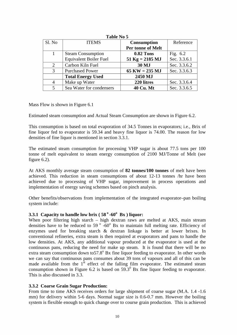
Table No 5
Sl. No ITEMS Consumption Per tonne of Melt
Reference
1
Steam Consumption Equivalent Boiler Fuel
0.82 Tons 51 Kg = 2185 MJ
Fig. 6.2 Sec. 3.3.6.1
2 Carbon Kiln Fuel 30 MJ Sec. 3.3.6.2 3 Purchased Power 65 KW = 235 MJ Sec. 3.3.6.3 Total Energy Used 2450 MJ 4 Make up Water 220 litres Sec. 3.3.6.4 5 Sea Water for condensers 40 Cu. Mt Sec. 3.3.6.5
Mass Flow is shown in Figure 6.1 Estimated steam consumption and Actual Steam Consumption are shown in Figure 6.2. This consumption is based on total evaporation of 34.5 Tonnes in evaporators; i.e., Brix of fine liquor fed to evaporator is 59.34 and heavy fine liquor is 74.00. The reason for low densities of fine liquor is mentioned in section 3.3.1. The estimated steam consumption for processing VHP sugar is about 77.5 tons per 100 tonne of melt equivalent to steam energy consumption of 2100 MJ/Tonne of Melt (see figure 6.2). At AKS monthly average steam consumption of 82 tonnes/100 tonnes of melt have been achieved. This reduction in steam consumptions of about 12-13 tonnes /hr have been achieved due to processing of VHP sugar, improvement in process operations and implementation of energy saving schemes based on pinch analysis. Other benefits/observations from implementation of the integrated evaporator–pan boiling system include: 3.3.1 Capacity to handle low brix ( 58 o -60o Bx ) liquor: When poor filtering high starch – high dextran raws are melted at AKS, main stream densities have to be reduced to 59 o -60o Bx to maintain full melting rate. Efficiency of enzymes used for breaking starch & dextran linkage is better at lower brixes. In conventional refineries, extra steam is then required at evaporators and pans to handle the low densities. At AKS, any additional vapour produced at the evaporator is used at the continuous pans, reducing the need for make up steam. It is found that there will be no extra steam consumption down to57.8o Bx fine liquor feeding to evaporator. In other words we can say that continuous pans consumes about 39 tons of vapours and all of this can be made available from the 1st effect of the falling film evaporator. The estimated steam consumption shown in Figure 6.2 is based on 59.30 Bx fine liquor feeding to evaporator. This is also discussed in 3.3. 3.3.2 Coarse Grain Sugar Production: From time to time AKS receives orders for large shipment of coarse sugar (M.A. 1.4 -1.6 mm) for delivery within 5-6 days. Normal sugar size is 0.6-0.7 mm. However the boiling system is flexible enough to quick change over to course grain production. This is achieved

11
by increasing the size of R-2 & R-3 sugar seed magma supplied to the continuous pans to 0.9-1.2 mm. This change has found to have no impact on energy usage. 3.3.3 Crystal Yield In the VKT’s the density of R-1 Massecuite is conveniently maintained at 90.5-91o Bx, in spite of low temperature steam and the crystal yield achieved is around 60%. Due to this only 54.5 % of R-1 Light Run Off syrup is recirculated (figure 6.1) against 67.6 % if lower yields of 50% were achieved (Figure 4.2). Hence, lower steam consumption for R-1 boilings. 3.3.4 Use of High Colour Seed: R-2 sugar used for seed preparation is typically 80-100 colour and R-3 sugar is 200 ICU. Usually this seed is of 0.35 to 0.4 mm size and is developed to 0.6 to 0.7 mm size by boiling on 175 colour fine liquor and R-1 light run off syrup. In this arrangement the visual appearance of product sugar is uniform and of good colour. No off coloured crystals are seen on visual examination because off coloured seed is developed from 0.35 mm to 0.7 mm product by boiling on low colour liquor or syrup .In the case of blending first, second and third or fourth strike crystals from batch pans, higher colour crystals can be seen on close examination. If a refinery has excessive stock of high colour sugar between 60-80 ICU, perhaps as a result of plant outages or due to other reasons, then the crystal can be easily developed to < 30 ICU without remelting, by using it in seed magma provided size and CV are within limits. With this arrangement 10-15% of high colour sugar can be mixed conveniently in the system. This provides a low energy way of recovering the sugar compared to remelting it. 3.3.5 Colour increase in 1st Effect of Falling Film Evaporator One consequence of the Case 2 system is that the boiling temperature of the liquor in the first effect is around 99oC. As a result, colour increases of about 15 % between fine liquor and heavy fine liquor have been observed .It is important to keep the liquor reducing sugar content low to prevent a larger colour increase. Residence time in the evaporator should be as low as possible and this should be checked at the design stage. 3.3.6 Energy and Water consumption AKS practice is to measure total energy consumption; i.e., boiler fuel, carbon kiln fuel, and electrical power. This provides a management focus on the total energy cost for the refinery, regardless of its form. 3.3.6.1 Boiler Fuel Consumption: The AKS boilers are oil fired. When melting VHP sugar at design rate, the monthly average total steam usage is 82 tons steam / 100 tonne melt, (ref. section 3.3 and Figure 6.3). Boiler fuel usage is 51 kg of Fuel per tonne of melt, which corresponds to steam energy usage of 2185 MJ / tonne of melt. 3.3.6.2 Carbon Kiln Fuel: Melting VHP sugar and other process improvements have reduced carbon usage and in turn reduced LPG consumption at the kiln. A monthly average usage equivalent to 30 MJ / tonne melt has been achieved.

12
3.3.6.3 Purchased Power: Presently AKS has no power generation plant. All electrical power is purchased from Dubai grid. When VHP sugar is processed, the affination station is shut down and there is no power used in the section. With no affination there is reduced load on recovery section equipments resulting in further power savings. Further, frequency drive units are used for Batch centrifugals, massecuite and magma pumps. Centrifugal pump drives are being changed to frequency drive wherever the pay back period is not more than one year. Monthly average power usage is 65 KW / Tonne of melt, which is inclusive of power required for sea water pumping and raw sugar ship unloading and conveying to raw sugar store. This corresponds to 235 MJ / Tonne of Melt. On this basis the average Total Energy Consumption is about 2450 MJ / tonne of melt. 3.3.6.4 Water Usage: All the process water is generated on site. All pan vapour is condensed in surface condensers and condensate recovered for process use. All the sweet water from desweetening filters and carbon columns, while sweetening on/off, is consumed in the process. Only small volumes of wastewater are discarded. As a result, fresh water make up at AKS average is 220 litres per tonne melt. 3.3.6.5 Sea Water Usage: Figure 6.2 shows that about 52 tonnes of vapours are sent to surface condensers. The surface condensers are cooled by fresh water circulated around a closed cooling circuit. This cooling water is cooled in turn by seawater pumped from the harbour through heat exchangers located close to the wharf. About 3600 - 4000 Cu. Mt./hr of seawater is pumped to cool the circulating freshwater. Seawater temperature varies between 27 o– 37 o C. 3.3.7 Instrumentation and Controls: The refinery control system makes an important contribution to maintaining energy usage at a low level. The Instrumentation comprises of Smart Field Transmitters and control valves while the control system uses a Distributed Control System (DCS), Programmable Logic Controllers (PLC) and Electronic Programmable Object Control System (EPOS) The DCS consists of ABB-Master Piece 200-Process Control Stations, Advant Operator Stations and remote I/Os are in turn connected to smart transmitters and control valves. PLC controls are used for some subsections-Boilers, Mud Desweetening Filters, Dryer / Cooler and Centrifugals. PLC s also communicates relevant information to the control room. 3.3.8 Programmes for future energy savings AKS has plans to further reduce energy consumption by implementing the following programmes: ♦ Change to processing VLC sugar (see ref no.14) so that carbonatation can be shut
down. Possible sources of VLC supply are being explored at present.

13
♦ Eliminating the fresh water cooling circuit and pumping sea water directly to cool the surface condensers: Using the existing sea water pump to pump directly to the surface condensers expected to save about 6-7 KW per tonne of Melt.
♦ Cogeneration – Installation of Power Generating Set: Installation of turbo-alternator is being planned to help reduce energy costs further.
With the implementation of these projects energy consumption is expected to reduce further towards the AKS benchmark for energy consumption of 2000 MJ / tonne melt. 3.3.9. CONCLUSION: Energy efficient refineries are the result of sound design and attention to detail in day-to-day operations. Considerable effort went into designing AKS with the clear aim of producing an energy efficient factory. That effort has now been rewarded with current operating performance now showing that total energy usage levels significantly below those achieved in conventional refineries. While processing VHP raws has been a significant contributor to current performance, the main reason has been the integration of pan and evaporator heating systems, using vapour bled from the liquor evaporator to heat the pans. The use of continuous rather than batch pans for white sugar crystallisation allows full benefit to be achieved from integration of the heating systems. ACKNOWLEDGEMENT: Authors are thankful to M/S Antonio Longakit, Sekhar Pachpute, Kanada Toto, M. Kanhere, P.G. Venkat and Raman for their help in preparation of this paper. REFERENCE 1. SUGARS Program for AKS, by L. Warner Weiss, 1991 2. SIT-93, paper no. 641, Michel Mabillot 3. SIT-94, paper no. 661, Chou C.C. & Clarke 4. ISSCT-92, Recent Development in continuous pan boiling, 105-118, Rein P W 5. SIT-97, Symposium on Energy Savings-Continuous Pan boiling, Rein PW, page 308-312 6 SIT-85, Paper 527, D Bosse & BMA bulletins 89, 91 7. SIT-94, Paper no. 668, Bosse & Farwick 8. BMA - ref no.1.61.00433, & 4 for AKS 9. SIT-88, Paper 574,Production and refining of Hawaiian High Pol, VLC sugars. 10. SIT-97, Symposium on Energy Savings by Jean-Paul Merle p 298-307 11. SIT-92, Energy conservation revisited, by K. Sinclair 12. Tongaat Hulett / Pinchtech reports on Pinch analysis for AKS in 96-97 13. Technical Review report on AKS Process operations by Field Technology Consulting Pty Ltd.-1998. 14. SIT-98.The VLC Sugar story, Paper 731,by P. Burns & P. Field

14

15

16

17

18

19

20

21

22

23