sugar industry technologists meeting · pdf filesugar industry technologists meeting 2000 may...
TRANSCRIPT
SUGAR INDUSTRY
TECHNOLOGISTS MEETING
2000
May 14-17
New Orleans, LA USA
S.I.T. Paper # 782
AL KHALEEJ SUGAR A WATER EFFICIENT REFINERY.
By
Jamal Al Ghurair & G.C. Singh, AL KHALEEJ SUGAR DUBAI, UNITED ARAB EMIRATES

2
ABSTRACT:
The Al Khaleej Sugar (AKS), a stand-alone refinery, located at the Jebel Ali Port of Dubai, United Arab Emirates, was designed in 1992-94, and was commissioned in 1995. The refinery has been operating at its design capacity of 100 tonnes of melt per hour since Nov’97. Refinery is located in Gulf, where fresh water is a costly item ($ 1.8 per Cu. Mt). Because of high cost of water, in this part of the world, it was desired that process technology at AKS would be such that it should have low water consumption than established refineries which are operating at water usage level of 1 to 1.5 Cu. Mt. of fresh make up water per tonne of melt.
At AKS we have achieved fresh water consumption of 0.2 Cu. Mt / per tonne of melt as annual average for 1999. This paper reviews the plant and process arrangements to achieve the above goals:
- Using all the sweet water within the process, - By using surface condensers for condensing vapours from evaporators
and vacuum pans, - Total recycling of all the condensates, - Use of steam transformers for purification of condensates & making it
suitable for boilers, - Compliance with environmental requirements, particularly in terms of
avoiding contamination of cooling water return to the harbour. 1) INTRODUCTION: During SIT-1999, a technical paper # 751 (ref no.1) was published by AKS, illustrating the methodology adopted for designing AKS as an Energy Efficient refinery, operating at 2450 MJ/tonne melt than established refineries which operated at usage levels of about 3500 MJ/tonne melt. AKS is pleased to announce that 600,000 tonnes of refined sugar were produced during the year 1999 at the energy consumption level of 2250 MJ/tonne of melt. We also achieved the best monthly average of 1925 MJ/tonne melt, equivalent (37 Kg of Fuel and 58 kWh of purchased power per ton of melt). We also improved our fresh water makeup consumption from 0.2 Cu. Mt. to 0.15 Cu. Mt. per tonne of melt. It was desired by some of the visiting Sugar Refinery Experts that AKS publish their design approach and methodology adopted, along with performance results, for benefit of other refiners where water is scarce and environmental control is mandatory. Hence, this technical paper is prepared, for the benefit of refineries and concentrates only on the design approach for optimisation of water and seawater usage.

3
2. METHODOLOGY: Steam and Water consumption were studied for different processes using SUGARS computer program (ref no.1, 2) for different operating conditions and various refinery configurations. Optimisation of the steam and water balance was critical for AKS because of the need to generate all the process water at site. To assist final decision-making, in view of water consumption, estimates were made for various plant configurations. The four typical arrangements are set out below in Table no. 1
TABLE 1 Estimated Water Consumption of Refinery in different arrangements
Sl. No.
Purification Process
Decolourisation Process
Estimated water Consumption Cu. Mt. Per tonne of melt Process Condensers (Fresh Water) (Sea Water)
1 Phosphatation & Ion Exchange 1.36 55- 65 2 Carbonatation & Ion Exchange 1.40 55- 65 3 Phosphatation & GAC Columns 0.16 55- 65 4 Carbonatation & GAC Columns 0.20 55- 65
Based on above study and hard data available from existing refineries it was concluded that refinery following Phosphatation for purification and GAC columns for decolourisation will have lowest water consumption. AKS decided to follow Carbonatation for purification and GAC columns for decolourisation, which is sufficiently robust combination, and at the same time has low water consumption. 2.1. Requirement of Water
Water is required at the following sections: - As condensates at Boilers for production of steam, - As hot water /sweet water in Process mostly at all the sections. - As condensing water at Condensers - As sealing/cooling at equipments
2.2. Water Losses Water is lost at following places and not recoverable economically - Blow down from boilers - Flash from various process tanks including Carbonatation Saturators - Filter Press Mud, - Carbon Slurry from GAC wastewater settling tank - Carbon Reactivation Furnace - Direct contact condensers - Centrifugals exhaust vapours, - Granulator exhaust air/vapours - Final Molasses - Condenser degassing; i.e., Non-Condensables via Vacuum Pumps - Purging from steam transformers - Effluent, Floor Washings etc
4
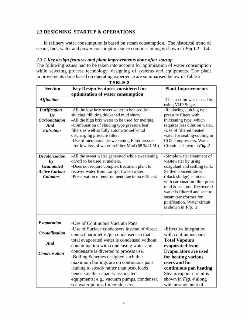
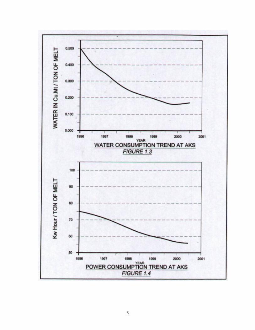
2.3 DESIGNING, STARTUP & OPERATIONS In refinery water consumption is based on steam consumption. The historical trend of steam, fuel, water and power consumption since commissioning is shown in Fig 1.1 - 1.4. 2.3.1 Key design features and plant improvements done after startup The following issues had to be taken into account for optimisation of water consumption while selecting process technology, designing of systems and equipments. The plant improvements done based on operating experience are summarised below in Table 2
TABLE 2 Section Key Design Features considered for
optimisation of water consumption Plant Improvements
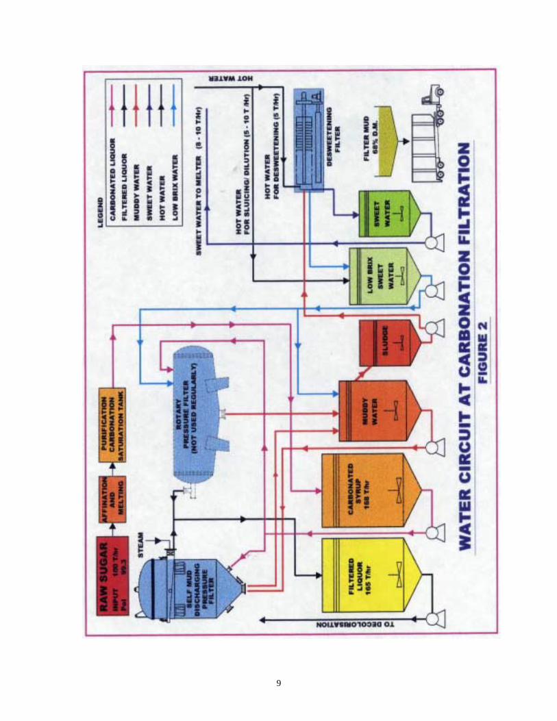
Affination Purification By Carbonatation And Filtration
-All the low brix sweet water to be used for sluicing /diluting thickened mud slurry. -All the high brix water to be used for melting. -Combination of sluicing type pressure leaf filters as well as fully automatic self-mud discharging pressure filter. -Use of membrane desweetening Filter presses for low loss of water in Filter Mud (68 % D.M.)
-This section was closed by using VHP Sugar. -Replacing sluicing type pressure filters with thickening type, which requires less dilution water. -Use of filtered treated water for sealing/cooling in CO2 compressors. Water Circuit is shown in Fig. 2
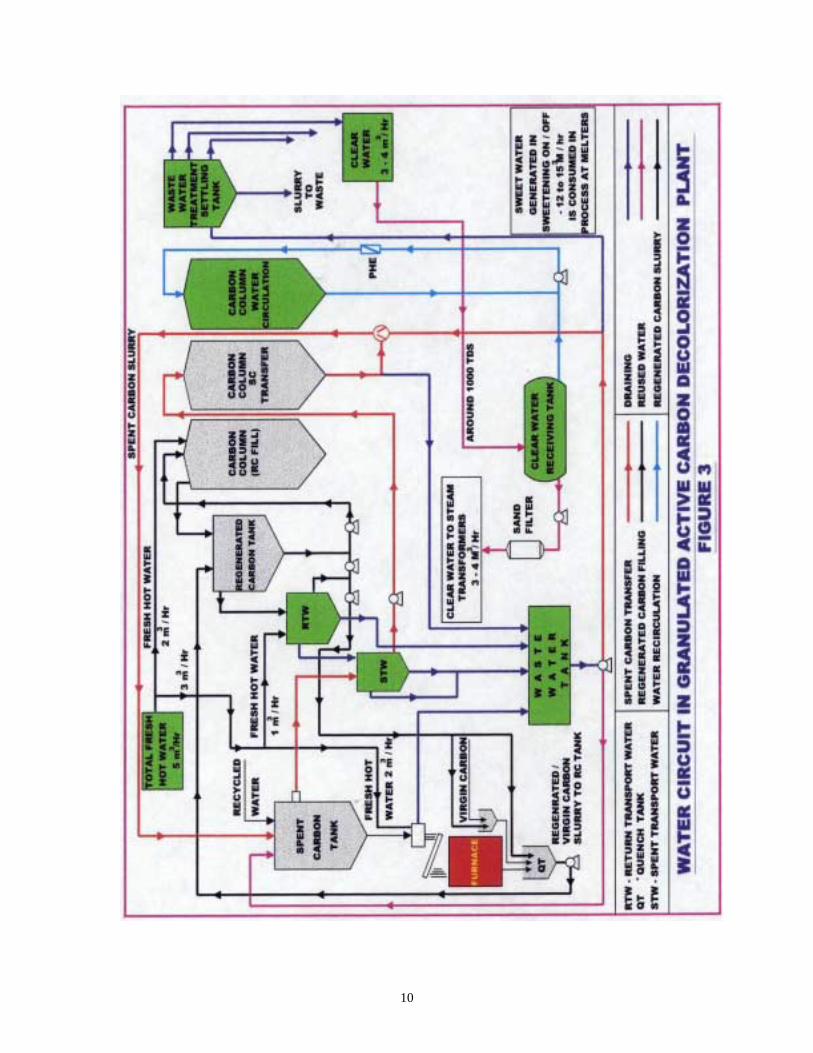
Decolorisation By Granulated Active Carbon Columns
-All the sweet water generated while sweetening on/off to be used at melters. -Does not require complex treatment plant to recover water from transport wastewater. -Preservation of environment due to no effluent.
-Simple water treatment of wastewater by using coagulant and settling tank. Settled concentrate is (black sludge) is mixed with carbonation filter press mud & sent out. Recovered water is filtered and sent to steam transformer for purification. Water circuit is shown in Fig. 3
Evaporation Crystallisation And Condensation
-Use of Continuous Vacuum Pans -Use of Surface condensers instead of direct contact barometric/jet condensers so that total evaporated water is condensed without contamination with condensing water and condensate is diverted to process use. -Boiling Schemes designed such that maximum boilings are on continuous pans leading to steady rather than peak loads hence smaller capacity associated equipments; e.g., vacuum pumps, condenser, sea water pumps for condensers.
-Effective integration with continuous pans Total Vapours evaporated from Evaporators are used for heating various users and for continuous pan heating Steam/vapour circuit is shown in Fig. 4 along with arrangement of
5
condensers.
Section Key Design Features considered for optimisation of water consumption
Plant Improvements
Drying And Cooling
-Use of dry dust collection system from exhaust of Drier/Cooler instead of wet scrubber, hence no requirement of sweet / hot water for melting dust sugar.
Condensate Collection
-Process is designed to operate at 1.4 bar a, 0.75 bar a, 0.48 bar a. -Separate condensate collection system for each operating pressure. -All the high-grade condensate (1.4 bar a) is sent to steam transformers. -All the low grade condensate (0.7,0.48 bar) is used in process for melting, desweetening, sluicing, sweetening on and off of GAC columns etc. Only in imbalance situation excess condensate is sent to steam transformers.
-Installing flash tanks in condensate tanks.
Purification Of High Grade Condensate in Steam Transformers
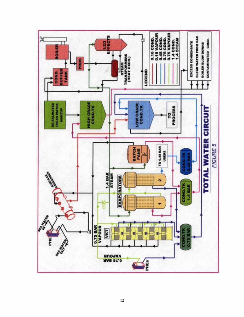
-Use of Steam transformers (see ref. no. 3), plays the role of interface between the refining process and energy production for production of clean condensates, making it suitable for use in boilers. -The steam production plant, pressure reducing & desuperheating, steam transformer and return of uncontaminated condensate constitute primary loop of energy production. -The steam transformer, refinery and return of excess condensates constitute the secondary loop. In this arrangement excess condensates of the refinery can be recycled in the secondary loop of the steam transformer, even if they are temporarily slightly contaminated with sucrose. -Proper sizing of steam transformers with flexibility of changing from single effect to double effect is available when required. --Use one of the units of transformer as concentrator of blow down from boilers, carbon plant, in order to recover water.
Usually 3 units of steam transformers are run as single effect. During the melting stoppages, short shutdowns & liquidation of boiling house there are situations when condensates are in excess of demand. During this period 2 units are run in series as double effect in order to purify excess condensate. Use one transformer to concentrate the blow downs from boilers, clear water from carbon plant, in order to recover water Total water circuit is shown in Figure 5

6
2.3.2 OPERATING EXPERIENCE: The designed goals on water consumption were achieved during the year 1999. The annual consumption for fresh water make up has been 0.2 Cu.Mt and the best monthly average usage levels have been 0.15 Cu.Mt/tonne of melts. This has been possible due to optimising energy consumption, plant improvement and total recycling & possible recovery of condensates. The seawater pumping to condensers for condensation have been around 40 Cu. Mt per tonne of melt. This has been reduced mainly by integration of evaporator and continuous vacuum pans (ref no. 2). Key performance indicators are tabulated below in Table No. 3.
Table No 3 Sl. No ITEMS Consumption Ref
Per tonne of Melt 1
Steam Consumption Equivalent Boiler Fuel
0.62 Tons Fig 1.1 37 Kg = 1650 MJ Fig 1.2
2 Carbon Kiln Fuel 65 MJ 3 Purchased Power 58 KW = 210 MJ Fig 1.4 Total Energy Used 1925 MJ 4 Make up Water 0.2 Cu. Mt Fig 1.3 5 Sea Water for condensers 40 Cu. Mt
2.3.3 PROGRAMME FOR FUTURE WATER SAVINGS: AKS has following future water saving programmes: 1. Recovery of flash vapours from Carbonatation/Saturators, 2. Installing a separate small steam kettle to concentrate the purges from steam transformers to recover the water without any extra energy. 3. Installing a water treatment plant for capacity of 10 Cu. Mt per hour for treatment of excess Condensates at the time of shut downs, floor washings. The treated water will be used at steam transformers when refinery is in operation and for irrigation purposes during shutdown. 3.0 CONCLUSION -The water saving programmes at AKS has met the designed goals due to sound engineering and attention to detail in day-to-day operations. -Use of Steam transformers ensures good quality condensates for boilers. -Use of Surface condensers for condensing vapours has contributed to maximum saving of water. About 40-41 tons of the evaporated vapours are sent to condenser, which returned as condensate to collecting tank due to use of surface condensers. -Use of Surface condensers also avoids contamination of cooling water return to harbour, complying with environmental requirement ACKNOWLEDGEMENT Authors are thankful to M/S.O. Hikmat, A. Longakit, A. Shabib, G. Nazimuddin, S. Pachpute, Dani, Venkat & Raman for their help in preparation of this paper. REFERENCES: 1. SIT-99, paper no 751, AKS –An Energy Efficient Refinery by J. Alghurair & GC Singh 2.Sugars Program for AKS, L. Warner Weiss, 1991. 3. SIT-98, paper no.724, Optimisation of Energy at Begin Say, by M. Mabillot.

7
8
9
10

11
12