subsea pipeline electrical heat trace (eht) – “active” … · 1 subsea pipeline electrical...
TRANSCRIPT
1
SUBSEA PIPELINE ELECTRICAL HEAT TRACE (EHT) – “ACTIVE” HEATING – APPLICATION FOR A DEEP WATER BROWN FIELD
DEVELOPMENT
C. Candelier, S. Durica, Total E&P - Paris, F. Beys, Total E&P Nigeria This paper was presented at the 12th Offshore Mediterranean Conference and Exhibition in Ravenna, Italy, March 25-27, 2015. It was selected for presentation by OMC 2015 Programme Committee following review of information contained in the abstract submitted by the author(s). The Paper as presented at OMC 2015 has not been reviewed by the Programme Committee. ABSTRACT Subsea pipeline electrical heating is a relatively new technology in the Oil & Gas industry that has been developing, quite intensively during the last 15 years. There are two main techniques considered for subsea pipeline electrical heating; the first one, already deployed and in use, is Direct Electrical Heating (DEH) and the second one, currently in the final stage of the technology readiness process, is Electrical Heat Tracing (EHT). Electrical heating of subsea pipelines is expected to be increasingly deployed as an elegant technical solution to optimize the flow assurance management during production pipeline’s service life and as a cost saving solution bringing significant reduction of projects overall CAPEX and OPEX. TOTAL has been operating world’s unique EHT PiP (Pipe in Pipe) subsea system, installed as an industrial pilot as a part of the Islay (TOTAL UK) project. Following the success of Islay project, TOTAL has studied implementation of the EHT PIP technology for an on-going deep water brownfield development which consists in the production of new reservoirs as a subsea tie back to an existing FPSO. The “base case” field architecture, a hybrid loop concept, had been selected at initial conceptual study stage. Nevertheless, due to high CAPEX of the “base case” option, TOTAL decided to investigate alternative solutions for the preservation of the subsea production line during shut-down, among which an EHT system appeared as potentially attractive. Therefore, a study was conducted in order to assess if the EHT system is installable, safe, reliable, operable, efficient and environmentally sound throughout its required minimum operating life of twenty (20) years.
INTRODUCTION Flow Assurance is a relatively new term in the Oil & Gas industry. It mainly refers to the transfer of all the effluents (oil, gas, water, in some cases with sand transport) from the reservoir up to the export by complying with the fluid chemistry constraints. In fact, beneath these terms is a transversal and multidisciplinary approach which involves a large number of players in the domains of reservoir, well performance, process, fluid chemistry, etc. Nowadays, flow assurance problems encountered in Oil and Gas industry have become more onerous, leading to increased industry awareness. This is the case particularly offshore, where low temperatures / pressures at wellhead, complex and viscous fluids, remote locations, harsh environment and great water depths of subsea environments conspire to exacerbate problems such as plugging or flow path reduction by hydrate or wax deposition, or topsides' facilities shutdowns due to severe slugging, etc. The ramifications of these events can be very serious, incurring significant intervention costs and substantial production revenue losses. All the problems introduced here above are further amplified by reservoir depletion that for sure will affect the flowing pressure and the fluid composition and characteristics over the production life. A good design based on initial flow characteristics may become inappropriate to end of life conditions. These considerations impose to the offshore industry changing its face and its rules.

2
With most of the world’s largest and easiest-to-exploit deepwater reservoirs already under development or producing, the industry is now facing new challenges. The tie-back of new smaller fields, often with complex fluids, to existing production facilities; or the transportation of multiphase production over long distances using large pipe diameters can appear as a viable route to unlocking reserves, which are often too small to be developed economically as a stand-alone facility. For such field developments,
The use of high insulated pipeline (Pipe in Pipe system offering U-value in between 0.7 and 2 W/m2K) can never be fully avoided.
The current operating procedures (Live Oil displacement for production lines preservation, hot Dead Oil circulation for production lines warm-up prior restart, etc.) can become unrealistic and can be challenged by developing new subsea architectures.
If the use of subsea technologies and innovative field architectures is a step change in the industry for the development of such complex fields; operators will always have nevertheless to face inherent Flow Assurance challenges described earlier in this paper.
This paper reflects the TOTAL views and addresses the way forward regarding the future successful implementation of the EHT technology for pipeline systems active heating through the example of a tie-back to existing facilities, provides technical comparison between the two cases, base case with service line and optional case with EHT pipeline, and summarises technical and economical benefits that EHT technology could bring in the case of brown fields developments, from the seabed up to the topside.
OVERVIEW OF THE MAIN ELECTRICAL HEATED PIPELINE TECHNOLOGIES
Active heating technologies are widely field proven technologies for onshore applications in Oil Gas industry where the various constraints through the service life (power transport, space, maintenance, etc.) are more manageable than in subsea-offshore applications. Today onshore electrical heating systems have very low failure rates, mainly due to improved fabrication technology, new materials and requirements from various industry standards that must be met in order to be accepted as a viable solution in different Oil Gas market segments.
Industrial use of electrical energy for the heating started with the trace heating solutions begging the 1930's.. Mineral insulated cables were run at high current densities to produce heat, and control equipment was adapted from other applications. Mineral-insulated resistance heating cable was introduced in the 1950's, and parallel-type heating cables that could be cut to length in the field became available. Self-limiting thermoplastic cables were marketed in 1971. Control systems for the electric heating systems were developed from capillary filled-bulb thermostats and contactors in the 1970's to networked computerized controls in the 1990's, in large systems that require centralized control and monitoring.
International standards applied in the design and installation of electric trace heating systems includes IEEE standards 515 and 622, British standard BS 6351, and IEC standard 60208. Until now, these technologies have been commonly used for the following applications:
Pipe freeze protection in cold environment (Alaska, etc.): Pipes are insulated and an electrical system is put on it, equipped with start/stop control logic. A thermostat is used to energize the trace heating when it measures temperature falling below a set temperature value - usually between 3°C and 5°C and often referred to as the 'set point'. The thermostat will de-energize when it measures temperature rising past another set temperature value - usually 2°C higher than the set point value.
Pipe temperature maintenance: The combination of trace heating and the thermal insulation, appropriate to the ambient operating temperature, maintains a thermal balance where the heat output from the trace heating matches the heat loss from the pipe. This application is relevant to prevent pipe blockage.
Long line heating Tanks, vessels heating such as storage tanks, etc. Foundation heating (LNG tanks, etc.) Snow and ice melting

3
Fig 1: Heating cables in onshore plant & heating panels for tanks heating
Subsea Pipelines Electric Heating Solutions - Introduction
In order to help to solve mainly flow assurance issues, electrical heating technology entered offshore pipeline market at the end of the 1990’s with Statoil’s development of the first subsea Direct Electrical Heating (DEH) wet insulated pipeline for the Åsgard field some 200 km west of Nord-Trøndelag, Norway. Eventually the Åsgard world’s first DEH pipeline was installed in year 2000. Following the DEH success, during the last 15 years two new electric heating solutions have been introduced to the offshore pipeline market, each of them with different philosophy regarding the design, operability and efficiency, the first is DEH – PIP and the second is EHT PIP solution.
Direct Electrical Heating (DEH) – Wet Insulated Pipeline
Principle
The technique is based on the fundamental principle that an electric alternative current (AC) in a metallic conductor generates heat due to Joule resistive effect. In the DEH system, the steel pipe wall is acting itself as a metallic conductor. This system has been developed originally for pipeline with wet insulation.
Fig 2: Configuration Wet-DEH system
In the DEH system, the pipe to be heated is an active conductor in a single-phase electric circuit (AC), together with a single core power cable as the forward conductor, located in parallel with and close to the heated pipe (Fig 2:).
4
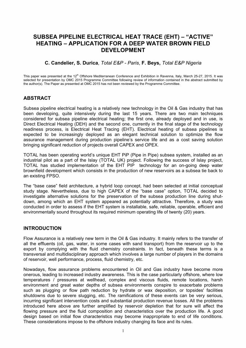
The heating system is supplied from the topsides power supply, from which two riser cables provide the electric power to the heating system. One of the two single core riser cables is connected to the near end of the pipe, and the other to the forward conductor, which is connected to the outmost end of the pipe. The power rating of such a DEH system is dependent on many factors:
Pipeline characteristics (electric and magnetic data of pipe steel, pipe dimensions, pipe insulation, length)
Design criteria (ambient seawater temperature, hydrate formation temperature, required heating time)
Cable data (voltage, conductor cross section...) For safety and reliability reasons, the heating system is electrically connected (i.e. earthed) to surrounding seawater through several sacrificial anodes for a length of ~50m at both ends where the cables are connected.
Fig 3: Principle of DEH system
Track record
The DEH system has been developed initially within a Joint Industry Project (JIP) initiative in 1996-1997 (Nexans Norway and Sintef Energy Research) based on a patent owned by Statoil. For maintaining required production fluid temperature, so far DEH has been applied in nearly 20 different field-developments mainly in North Sea, Norway. The system has been successfully operated with operational experiences confirming simulated results and lab tests.
Advantages and drawbacks
The main advantages and drawbacks of the DEH for wet insulated pipelines are summarized in the following table.
Tab. 1: Advantages and drawbacks – DEH Wet insulated pipelines
Advantages Drawbacks
Design
Direct heating of the pipeline steel by Joule effect
Low requirements for U-value (2.5 W/m2K)
Long heating circuits (~50km)
Big diameter pipelines, (up today ID 30”)
High currents (1500A), high voltages and high linear power
Need for 3-to-1 phase adaptation
Large cathodic protection system required
Electric field (AC) phenomena critical for the pipeline corrosion design
Fabrication Field proven Sorting of the line pipes by magnetic
permeability
Piggy back cable strapping and protection

5
Installation S-Lay, J-Lay, Reel Lay Limiting application for deepwater (up to
1000m WD)
System
Efficiency Field proven
Low electrical efficiency 30 - 60%
Low heating efficiency 50 – 75%
Not efficient for continuous heating
Reliability /
Reparability
Cable and components could be repaired / retrofitted (envisaged during system design)
No redundancy
Conclusion
The system heating efficiency is low as consequence of the pipe low thermal insulation capacity and low electrical efficiency that is estimated to be 30 - 60% (energy is lost mainly due to Joule effect in the DEH piggy-back cable and power lost in sea water). As such system is not preferred option for continuous heating solutions (high power requirements on topside). On the other side system concept is field proven, robust, applicable for relatively long and big diameter pipelines that could be installed in any installation method (S-Lay, J-Lay or Reel Lay).
Direct Electrical Heating (DEH) - PIP
Principle
The system has been developed by Shell and is relevant for the Pipe-in-Pipe technology. Originally, the DEH for Pipe-In-Pipe has been developed first as a tool for hydrate remediation; but this technology can also be applicable for the heating of the flowline during field production shutdown and / or for fields’ development (continuous heating).
Fig 4: DEH PIP Concept
Fig 5: Mid-Line assembly (MLEC) of Shell DEH PiP
The system is also called the “Electrical Heating Ready System” and its principle is as follows: Production line is split into heated segments (each segment is equivalent to a close
electrical circuit composed of inner and outer pipe). Each heated pipe-in-pipe segment is terminated at both ends with a steel bulkhead (Fig 5:)
in order to have a closed electrical circuit. A plug-in high-voltage high-amperage electrical connection can be made in the center of
the flowline segment at the Mid-Line Electrical Connector (MLEC, Fig 5:). Current will flow from the MLEC in both directions through the inner pipe wall, via the
bulkheads, and back through the outer pipe wall.
6
Skin effect and proximity effect keeps the current on the outside of the inner pipe and inside of the outer pipe, so there is no risk of current leakage to the environment, with associated corrosion problems.
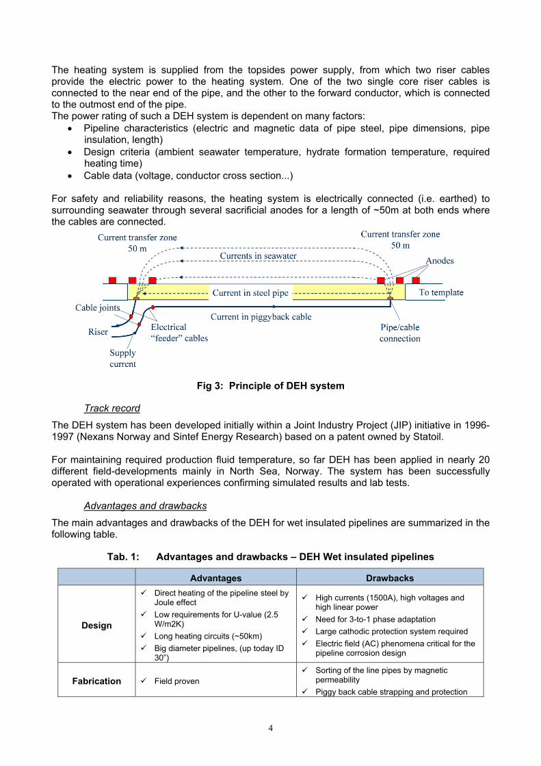
If a hydrate plug forms in one of the segments, an electrical heating spread will be mobilized to the field to heat up this segment in a matter of days. The heating spread includes (Fig 6:):
A subsea transformer with flying leads, An umbilical and reel, A surface switch gear, A generator on a vessel of opportunity.
Fig 6: DEH PIP – Heating Spread on one segment – Plug remediation
Compared to the DEH system coupled with wet insulation, this solution presents higher power efficiency for the following reasons:
There is no communication with the seawater, thanks to the skin and proximity effects, The thermal losses are decreased, thanks to the PIP insulation.
However this system requires specifically designed components such as non-metallic bulkheads and seems limited to medium lengths: longer lengths would lead to higher voltage and large annulus width for electrical isolation purposes.
Track record
The track record of this solution is limited to three Shell’s projects where the heating system was designed for remediation on-demand only. In Serrano/Oregano development, 20 shutdowns have occurred between 2002 and 2007 and, each time, the heating system has been used successfully.
Tab. 2: DEH-PIP technology – Track record
SERRANO
OREGANO HABANERO NAKIKA
Main operator Shell Shell Shell
DEH system designer Shell / INTEC Shell / INTEC Shell / INTEC
Installation year 2001 2003 2004
Installation method J-Lay J-Lay J-Lay
Water depth (m) 900m 700m 1800m
Length (km) 11km
13km 2x7km
11km
13km
2x2km
7km
5km
Pipe ID (in.) 6’’x10’’ 6’’x10’’ 10’’x16’’
Advantages and drawbacks
The main advantages and drawbacks of the DEH for PIP are summarized up in the following table.

7
Tab. 3: Advantages and drawbacks of the DEH technology for wet insulated pipes
Advantages Drawbacks
Design Voltage level at 3kV
High thermal performance (U-value from 2 to 0.5 W/m2K)
High currents (1500A) and high linear power
Low lengths flowlines
Long power cable required for electricity supply at mid pipeline location.
Fabrication Field proven Need for specific bulkheads & waterstops
Installation Preferred J-Lay and Reel Lay
Applicable in deepwater S-Lay not preferred
System
Efficiency High heating efficiency up to 95%
Relatively low electrical efficiency up to 70%
Not applicable for continuous heating
Reliability /
Reparability
Cable and components could be repaired / retrofitted (envisaged during system design)
No redundancy
Conclusion
The system heating efficiency is high as consequence of the PIP high thermal performance with low electrical estimated to be up to 70%. System is not preferred option for continuous heating solutions. On the other side system concept is field proven, robust, and pipelines could be efficiently installed in J-Lay or Reel Lay installation methods.
Electrical Heat Trace PIP (EHT-PIP)
Principle
EHT PIP system has been developed during the last 10 years, with 3-phase insulated trace heating wires installed around the inner pipe under insulation layer in PIP annulus and terminated in star end connector (see Fig 7:). The Joule resistive effect of these 3-phase electrical wires attached to the production generates heat which is then transferred to the inner/production pipe by conduction.
Fig 7: Three-phase star configuration.
The use of EHT PIP for max size pipelines (ID 12in) is at the moment limited to relatively short distance (up to 25km) with use of low to medium voltage (1 to 3.6kV) cables. For EHT PIP temperature monitoring and control along the whole pipeline length is added fibre optic cable (FOC) as integrated part of the system. To extend the use of such systems, there are several possibilities:
Multiplication of the number of cables, Reduction of the heating power per meter by use of high-performance insulation
technologies, Regular power re-alimentation of the heating system. Qualification of new equipment (high power cables and wet mate connectors)
8
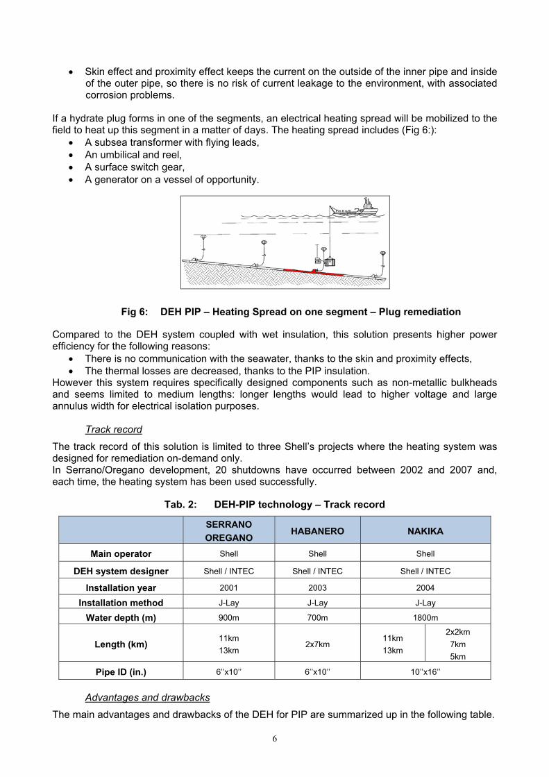
Fig 8: EHT PIP Technip Concept
Installation means
The EHT PIP is currently qualified only for reel lay or towing installation method. This installation method appears as the most relevant for this heating technology as number of wire field slices is minimised. Nevertheless, reel lay is suitable only for limited inner pipe diameters up to 12”, so the installation of larger inner/production pipes will require use of other installation methods.
Advantages and drawbacks
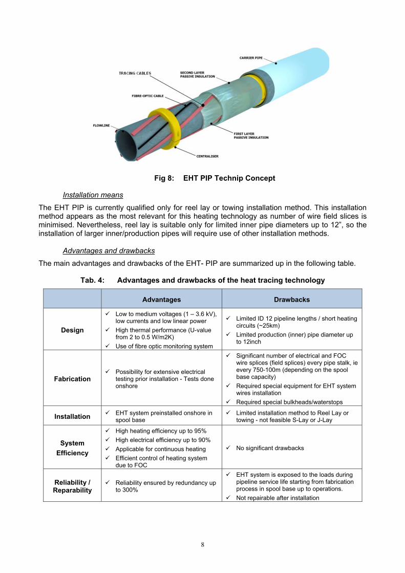
The main advantages and drawbacks of the EHT- PIP are summarized up in the following table.
Tab. 4: Advantages and drawbacks of the heat tracing technology
Advantages Drawbacks
Design
Low to medium voltages (1 – 3.6 kV), low currents and low linear power
High thermal performance (U-value from 2 to 0.5 W/m2K)
Use of fibre optic monitoring system
Limited ID 12 pipeline lengths / short heating circuits (~25km)
Limited production (inner) pipe diameter up to 12inch
Fabrication Possibility for extensive electrical
testing prior installation - Tests done onshore
Significant number of electrical and FOC wire splices (field splices) every pipe stalk, ie every 750-100m (depending on the spool base capacity)
Required special equipment for EHT system wires installation
Required special bulkheads/waterstops
Installation EHT system preinstalled onshore in spool base
Limited installation method to Reel Lay or towing - not feasible S-Lay or J-Lay
System
Efficiency
High heating efficiency up to 95%
High electrical efficiency up to 90%
Applicable for continuous heating
Efficient control of heating system due to FOC
No significant drawbacks
Reliability / Reparability
Reliability ensured by redundancy up to 300%
EHT system is exposed to the loads during pipeline service life starting from fabrication process in spool base up to operations.
Not repairable after installation

9
TOTAL’S EXPERIENCE WITH EHT-PIP SYSTEM
Flow assurance & operability benefits
The main benefits offered by the EHT PIP technology, in terms of Flow Assurance & field operability, are discussed here after.
During unplanned/planned shutdown, o Hydrate mitigation: The production fluid temperature can be maintained above
Hydrate Dissociation Temperature by switching the electrical system on. The fact that the production line is maintained in temperature considerably simplifies the operating procedures on the production platform. This is particularly appreciated in the case of an unplanned shutdown (excluding ESD0 event).
o Oil gelling prevention: The production fluid temperature can be maintained above Pour Point temperature in order to prevent oil gelling issues within production line. Such operating philosophy is relevant for production fluid presenting high Pour Point temperature and simplifies considerably restart operations.
WAX and hydrates mitigation in production: For low temperature reservoirs or long tie-back, the heating system can be operated in continuous mode during in low flowing/turndown scenarios to maintain the fluid temperature above either the Wax Appearance Temperature (WAX) or hydrate formation temperature along production line.
Production line warm-up (after ESD0 or extended shutdown): After an extended shutdown or an ESD0, the fluid might cool down to ambient conditions. In order to prevent operating issues during restart, the production fluid has to be warmed up prior to start up or restart at a desired temperature (Minimum Safe Temperature). The required time to reheat the system is a critical parameter in design which may dictate maximum power requirements of the electrical heating systems.
Hydrate remediation: In the event of a hydrate plug forming, the electrical system can be brought online in order to melt the hydrates plug. In order to manage inherent safety issues related to such remediation procedures, pressure monitoring and temperature monitoring with FO and especially a monitoring of the power supplied to EHT PIP system are deemed mandatory. Raising the flowline temperature above the hydrate dissociation temperature at such a rate that the gas is released locally in a rapid manner may cause pressure build up leading to pipeline rupture. In addition, the heating system could dislodge the hydrate plug where a large pressure drop exists across it, propelling it like a bullet within the pipeline. A Hydrate Plug Management Project is on-going on this subject.
Liquid hold-up monitoring during shutdown: As liquid presents much higher thermal inertia compared to gas, the warm-up or cool-down of the liquid filled section will be much slower than the rest of the EHT PIP that contains gas. By using the FO temperature monitoring capability, operators have a direct access to liquid accumulation in the production line. In addition, taken into account fluid properties (heat capacity and density), the composition of the different liquid accumulations can be determined.
Fig 9: Warm-up sequence observed on DTS report – Islay pilot
Liquid Accumulation Liquid Accumulation Liquid Accumulation

10
Restart: By keeping the production fluid above a certain temperature during production shutdown, the viscosities and the back-pressure applied to production wellhead is minimized (riser full of gas as no more Dead Oil circulation). Well restart operations are thus easier, which is even more appreciated in deepwater applications.
The design of the EHT PIP is mainly governed by its requirement for use in the different operating scenarios described here above. Power supplied to EHT PIP is brought by essential generator.
BROWN FIELD DEVELOPMENT CASE – OPTIMIZATION WITH ETH PIP SYSTEM
Case description The study presented in this paper is based on a new Brown Field Development (referenced as BFD) that is located offshore West Africa in water depths from 600 to 1,200 m. The BFD is designed as a part of the existing field that covers an area of 600 km2 and that is bringing four existing fields into production thanks to four independent production flowline networks, all of them are tie backed with dedicated risers to existing FPSO unit.
Fig 10: Schematic overview of BFD case
The BFD consists in the development of the new reservoir with five production wells that are designed to be tied-back with production flowline network (including all inline structures) to the existing FPSO. The reservoir pressure maintenance is performed with Water Injection (WI).
Base Case - Layout and subsea architecture
Subsea layout
The subsea production system of BFD consists of 5 new production wells tie-in to 3 new manifolds and connected to the FPSO with 11km long production pipeline network. The production network for the BFD has been based on a new 12” ID hybrid loop system with
One single pipe-in-pipe production flowline that is design to transfer production to FPSO through the existing production riser (EPN1-IPB) and
One non-insulated service line for preservation purpose also tied back to the FPSO with separate new riser system.

11
Fig 11: Typical hybrid loop configuration
The production wells are planned to be activated with Bottom Hole Gas Lift while the riser base gas lift is planned to be used for flow stability purpose only. A new dedicated water injection system (flowline and riser) from existing FPSO unit has been also planned to be utilised for BFD production.
Topsides
On the existing floating FPSO unit, for the Base Case it has been planned installation of the new dedicated manifolds (production, water injection & gas lift injection), preservation equipment (dead oil pump, piping, etc.) and 3-phase slug catcher. The oil production is eventually sent to the existing second separation stage.
Operating principles of Base Case
Existing Production Network 1 (EPN1) based on standard production loop configuration (left branch –L and right branch – R) and new BFD hybrid production network are designed to be fully independent. The main principles for the management of the major flow assurance risks are:
Production fluid permanently outside of hydrate zone, Flowing temperature above the wax appearance temperature, Riser base gas lift injection for flow instability mitigation. In case of production shutdown, BFD production flowline to be preserved first.
Optional Case – Optimised field architecture with EHT PIP system
Subsea layout
Driven by the idea for the Base Case CAPEX optimisation, an alternative optional scenario has been developed through a value engineering study. The basis for the value engineering study has been build on following assumptions:
Instead of a hybrid loop solution to be installed only one EHT PIP, 11km long, for the production. Limitation for PIP system: Inner pipe ND of 12” while outer with maximum OD18”,
Reel lay installation method for EHT PIP, Tie-in of the EHT PIP to FPSO to be done via existing IPB-L riser of the EPN1 flowline
production loop at IPB-L riser base (Fig 12:), Cancelation of the manifolds. All 5 off production wells tie-in directly to the EHT PIP line
through 3 off inline structures: 2 off In-Line Tees (ILT) and one FLET, Installation of a Gas Lift (GL) flowline including the riser to provide gas for wells activation, Installation of dedicated umbilical to supply chemicals, control, etc. at riser base and
production / injection wells, Installation of a WI line for pressure management of the BFD production and directly
connected to the EPN-1 water network with a grouted tee.

12
Fig 12: Principle of field layout for subsea tie in & Riser base arrangement
As production manifolds have been replaced by inline structures (ILT and FLET) particular attention has been given to the structures design that has been resulting in following:
CAPEX savings: No manifolds. ILTs installed in line with production line. Installation planning reduced.
Better reliability and management of ETH cables and FOC through the structures. For instance, specific bulkheads with cable penetrators at both ends of the structures have been considered in order to guarantee electrical continuity through these structures and to enable partial heating of the well tie-in tees by deviated electrical wires.
Relatively compact design, within reel lay installation vessel capabilities, with regard to the different integrated functionalities (cold spots management, riser preservation, isolation of branch, production route, pigging, etc) in favour of an installation in a congested subsea area.
The weight of the heaviest flowline structure, FLET at the riser base has been estimated at about 90 tons. The specification of the umbilical for BFD production network has included requirements for:
Supply electric power to FLET (at riser base) for EHT PIP system Inject diesel into FLET (at riser base) for preservation. 6 x 1.5” service lines have been
integrated in the dynamic riser cross section. A Subsea Distribution Unit (SDU) at riser base to route power, chemicals and diesel to
FLET. Provision to inject diesel at riser base through the gas lift tubes of existing IPB riser (18 tubes of 1” ID) during preservation sequence, is also planned as presented here below.
Fig 13: Diesel injection points & IPB cross section
13
Several challenges associated to the use of the EHT PIP technology for deepwater applications have been identified during the study. Following recommendation have been specified to ensure integrity of the ETH PIP electric and FO system components during service life (20 years design life) including construction and installation:
ETH system components qualification program. Minimum EHT system redundancy requirements:
A. Two independent power supply chains each sized for 200% design conditions on FPSO for ETH system operation.
B. For flow line EHT heating system 200% redundancy (3 independent sets of power cables sized for 100% design conditions) while for FO temperature monitoring system 200% redundancy (2 independent sets of FO cables) in each of the following sub-systems: FPSO umbilical junction boxes to umbilical topside termination, dynamic umbilical, connection between umbilical SDU and FLET (at riser base side), PIP annulus, ILTs and end FLET.
Dual barrier at “entry” point of the ETH cables and FO into the PIP annulus to mitigate PIP annulus flooding.
Robust QA/QC system (integrity test/monitoring/checks of the EHT components) during ETH PIP sections fabrication/assembly in spool base and during reeling/unreeling process.
Dry environment for storage of ETH components and draying of PIP annulus after EHT assembly.
Water stops with water proof ETH system penetrators for the PIP annulus. Spare philosophy.
Estimated power requirement to maintain the fluid temperature at 30°C in the production line ranges from 250 kW to 320kW depending on the EHT PIP technology.
Operating principles of Optional Case
The main operating principles are kept with the following adjustments: Production mode
o Existing production is partially produced through EPN1. The second production line is then filled with diesel or dead oil.
o New BFD is produced through the EHT PIP flowline and the second riser of EPN1 IPB-L (i.e. left branch riser).
Production shut-down and restart o After NTT period, EHT PIP is powered in order to maintain the temperature in the
new production line installed on the field. o Production riser (EPN1 IPB-L) allocated to BFD is first displaced with diesel from
riser base to topsides. As soon as existing production riser EPN1 IPB-L is filled with diesel, the preservation of the EPN 1 right branch can be initiated. The fluid then circulates from Left to Right branch.
o BFD - EHT PIP line preservation and restart can be performed without impacting production through EPN1 production loop system. The restart operations are facilitated and accelerated thanks to the heat traced technology which allows maintaining the temperature in the production line at 30°C. MeOH is injected at riser base to prevent hydrate formation through cold spots.
o EPN1 production loop system, however, requires shutting of BFD production through EHT PIP, since the IPB-L production riser is used to displace EPN1 live fluid with diesel.
Topsides
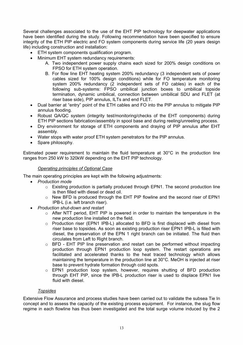
Extensive Flow Assurance and process studies have been carried out to validate the subsea Tie In concept and to assess the capacity of the existing process equipment. For instance, the slug flow regime in each flowline has thus been investigated and the total surge volume induced by the 2
14
production lines has been directly compared to the existing surge capacity of the separator (66 m3 with optimized alarm levels). Olga models were tuned to match available production history and thus to reduce the uncertainties inherent to the use of the Slug Tracking option. The studies demonstrated the capacity of the existing facilities to handle the end of life production of EPN1 and the production of BFD, and the slug catcher initially planned for the production of the BFD was finally removed.
Fig 14: Total surge volume in the MP separator for all the production years
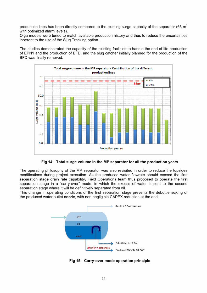
The operating philosophy of the MP separator was also revisited in order to reduce the topsides modifications during project execution. As the produced water flowrate should exceed the first separation stage drain rate capability, Field Operations team thus proposed to operate the first separation stage in a “carry-over” mode, in which the excess of water is sent to the second separation stage where it will be definitively separated from oil. This change in operating conditions of the first separation stage prevents the debottlenecking of the produced water outlet nozzle, with non negligible CAPEX reduction at the end.
Fig 15: Carry-over mode operation principle

15
The Optional Case option brings significant topsides weight savings compared to the Base Case, as shown on the 3D views of the topsides modifications.
Fig 16: Topsides 3D view – Comparisons between Base Case and Optional Case
Estimated cost saving with EHT PIP system
The Optional Case CAPEX savings associated to the simplification of the subsea architecture have been estimated at about 30% of the initial Base Case cost. Considering the relatively limited impact of due to the pipe diameter reduction on total reserves, the relevance of the proposed alternative solution has been confirmed for the field development.
The impressive cost reduction was possible mostly with the concurrence offered with the EHT PIP system and a significant reduction of the equipment required both subsea and on topsides for the development of the field compared to the base case.
The different savings are presented in the table here below.
Tab. 5: Estimated CAPEX savings summary
SUBSEA TIE IN COMPARED TO BASE CASE CAPEX
SAVINGS Packages Removed equipment Added equipment
Main diference
Topsides
Slug Catcher / heater module
Manifold module upgrade
Integrated loose items (pipe & valves)
Electrical cabinets for the heated PIP
Few piping lines (Diesel lines)
-1350 tons 7 %
UFR
12” production riser - IPB or equivalent
Shorter production line (1km)
Service riser and service line
WI riser & shorter WI line (2km)
Wye manifold @ Riser Base
Subsea Umbilical Termination
In Line Tee (3)
WI tie-in grouted tee
-12 km lines
-2 main risers 16 %
SPS Manifolds (3) & valves 4 SDUs and flying leads No manifold 7 %
TOTAL 30 %
Base Case: 1600 tons Optional Case: 250 tons
16
CONCLUSIONS
Offshore pipeline electric heating solutions have been initiated with DEH system for wet insulated pipelines. This technology therefore benefits from an extensive maturity and track record, but suffers from low power and heating efficiency.
EHT PiP, conceptually more preferred option in Total, has been developed more recently and the feasibility of the concept has been demonstrated with the world’s first EHT PIP system installed on Islay field (Total UK) as a pilot. This system offers higher heating performances and extended application range. The high efficiency, strong operability and with reduced CAPEX compared to a more conventional hybrid loop, the EHT PIP concept have contrived to consider this technology for some future Total’s brown field development mainly offshore West of Africa with.
In studied case application of the ETH PIP system brought considerable simplification in the brown field development subsea architecture, as the production riser and the service line are removed while on the FPSO topside have been estimated significant reduction in required equipment weight. The EHT PIP greatly facilitates the management of the production shutdowns and restarts and allows reducing chemicals injection. Indeed, the preservation/restart procedure simply consists in maintaining/bringing the production fluid temperature above Pour Point temperature and Hydrate Dissociation Temperature. The FO monitoring system implemented in the PIP annulus, coupled with the accurate power control offered with the EHT PIP technology enables a fine monitoring of the temperatures and the fluid phases distribution along all the production lines.
OPEX savings, also expected from the technology, may be quantified in later field life when the rates have declined and the operations become more problematic.
In the future, it is expected that subsea field developments will be essentially driven by minimization of investments. This will require continuous work on development of the new innovative technologies to which active heating systems can contribute as step changers. In that respect, the EHT PIP appears today as promising solution that could simplify subsea development philosophy and operations during field service life.
This technology seems particularly attractive for brown field developments where the tie-back to existing production platform is envisaged.
ACKNOWLEDGEMENTS
The authors gratefully acknowledge the support and encouragement they receive from TOTAL E&P while preparing this manuscript.
REFERENCES [1] - Decrin, M-K., Nebell, F., Naurois, H & Parenteau, T., 2013. Flow Assurance modelling using an Electrical Trace heated Pipe in Pipe: From Qualification to Offshore Testing, Offshore Technology Conference, OTC 24060.
[2] - De Naurois, H., Delaporte, D., Hellingoe, M., Hugues, G., (TOTAL). 2011. Evaluation Qualification of Electrically Heat Trace Pipe in Pipe for a SS Flowline and selection for an Application on a Subsea Field in the UK, ISLAY, OTC 21396.
[3] – K.A. Esakul, G. Fung, G. Harrison, R. Perego, BP America, 2003. Active Heating for Flow Assurance Control in Deepwater Flowlines, OTC 15188.
[4] - S. Denniel, J. Perrin, A. Felix-Henry, TECHNIP, 2004. Review of Flow Assurance Solutions for Deepwater Fields, OTC 16686
[5] – David M March, Ronald M Bass, Shell International Exploration and Production, EP Projects; David K Phillips, INTEC Engineering Robust Technology. 2003. Implementation Process Applied to a First Deepwater Electrical Heating Ready System, OTC 15145
©T
ep Ita
lia
SUBSEA PIPELINE ELECTRICAL HEAT TRACE
(EHT) – « ACTIVE » HEATING – APPLICATION FOR
A DEEP WATER BROWN FIELD
Christophe CANDELIER – TOTAL E&P – Flow Assurance specialist
AGENDA
Introduction
Overview of main heating technologies
Benefits of the Electrical Heat Traced – Pipe In Pipe (EHT-PIP)
Brown field application case – Comparisons of subsea architectures -
EHT-PIP vs. Single production line looped with service line
Conclusion
2 Subsea pipeline EHT - Application for a deep water brown field – OMC 2015 – 25-27 March 2015

INTRODUCTION
3 Subsea pipeline EHT - Application for a deep water brown field – OMC 2015 – 25-27 March 2015
INTRODUCTION
GENERAL CONTEXT
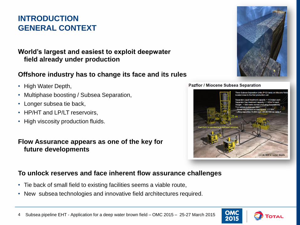
World’s largest and easiest to exploit deepwater field already under production
Offshore industry has to change its face and its rules
• High Water Depth,
• Multiphase boosting / Subsea Separation,
• Longer subsea tie back,
• HP/HT and LP/LT reservoirs,
• High viscosity production fluids.
Flow Assurance appears as one of the key for future developments
To unlock reserves and face inherent flow assurance challenges
• Tie back of small field to existing facilities seems a viable route,
• New subsea technologies and innovative field architectures required.
Subsea pipeline EHT - Application for a deep water brown field – OMC 2015 – 25-27 March 2015 4

OVERVIEW OF MAIN HEATING
TECHNOLOGIES
5 Subsea pipeline EHT - Application for a deep water brown field – OMC 2015 – 25-27 March 2015

OVERVIEW OF MAIN HEATING TECHNOLOGIES
DIRECT ELECTRICAL HEATING
Direct heating technology
• Pipe used as an electrical conductor
• Electrical return made by a cable
Development steps
• Patent owned by Statoil
• Developed through a JIP initiated in 1996 – 1997 by Nexans and Sintef
Incentives of the technology
• Distance: <50km (Tyrihans – 43 km – Qualification of a DEH system with cable rated at 52kV)
• Safety: pipe electrically connected (i.e. earthed) to surrounding sea water Sacrificial anodes to
control stray currents
• Power achievable: 50 - 150W/m
• Fully compliant with reeling and S-lay methods
• WEAKNESS: Efficiency: ~25 – 50 %
• STRENGTH: High reliability & no electrical
insulation required, Large diameter
Subsea pipeline EHT - Application for a deep water brown field – OMC 2015 – 25-27 March 2015 6
OVERVIEW OF MAIN HEATING TECHNOLOGIES
ELECTRICAL HEAT TRACED - PIPE IN PIPE
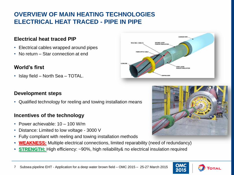
Electrical heat traced PIP
• Electrical cables wrapped around pipes
• No return – Star connection at end
World’s first
• Islay field – North Sea – TOTAL.
Development steps
• Qualified technology for reeling and towing installation means
Incentives of the technology
• Power achievable: 10 – 100 W/m
• Distance: Limited to low voltage - 3000 V
• Fully compliant with reeling and towing installation methods
• WEAKNESS: Multiple electrical connections, limited reparability (need of redundancy)
• STRENGTH: High efficiency: ~90%, high reliability& no electrical insulation required
Subsea pipeline EHT - Application for a deep water brown field – OMC 2015 – 25-27 March 2015 7
BENEFITS OF THE EHT-PIP
8 Subsea pipeline EHT - Application for a deep water brown field – OMC 2015 – 25-27 March 2015
BENEFITS OF THE EHT-PIP TECHNOLOGY
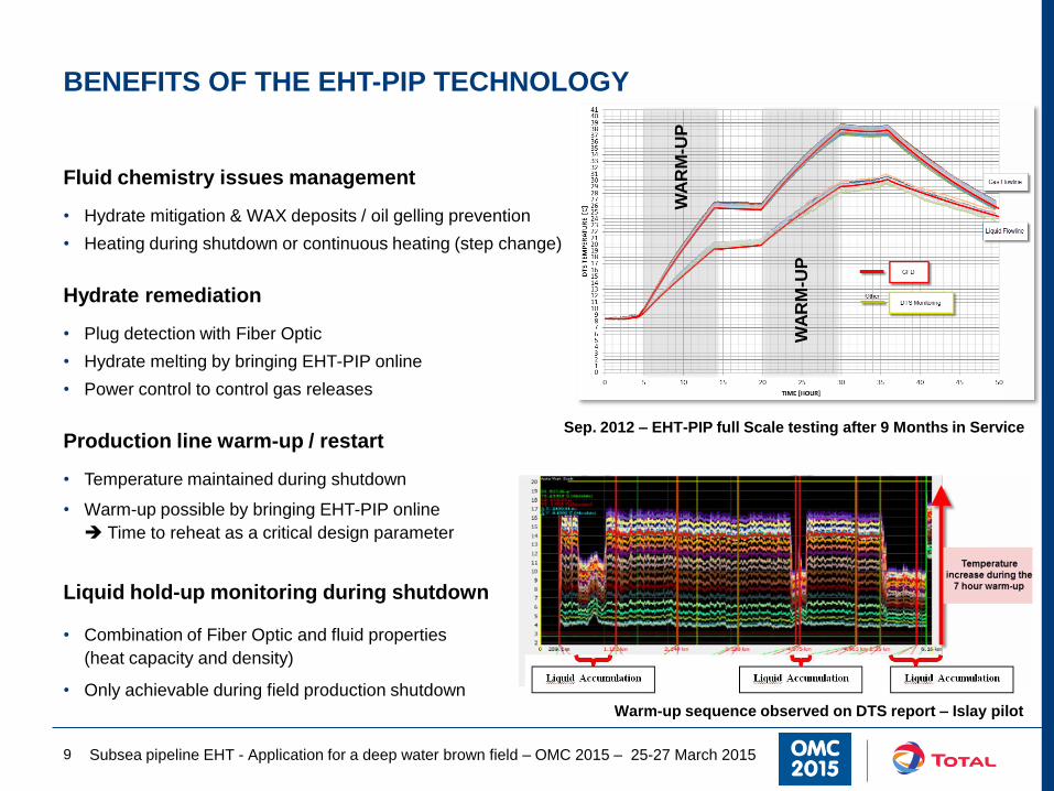
Fluid chemistry issues management
• Hydrate mitigation & WAX deposits / oil gelling prevention
• Heating during shutdown or continuous heating (step change)
Hydrate remediation
• Plug detection with Fiber Optic
• Hydrate melting by bringing EHT-PIP online
• Power control to control gas releases
Production line warm-up / restart
• Temperature maintained during shutdown
• Warm-up possible by bringing EHT-PIP online
Time to reheat as a critical design parameter
Liquid hold-up monitoring during shutdown
• Combination of Fiber Optic and fluid properties
(heat capacity and density)
• Only achievable during field production shutdown
Subsea pipeline EHT - Application for a deep water brown field – OMC 2015 – 25-27 March 2015 9
Warm-up sequence observed on DTS report – Islay pilot
Sep. 2012 – EHT-PIP full Scale testing after 9 Months in Service
WA
RM
-UP
WA
RM
-UP

BROWN FIELD APPLICATION CASE
10 Subsea pipeline EHT - Application for a deep water brown field – OMC 2015 – 25-27 March 2015

BROWN FIELD DEVELOPMENT CASE
GENERAL DESCRIPTION
Field description
• West of Africa - Water Depth: 600 – 1200 m
• Field extension: 600 m2
• 4 independent production networks tie back to a FPSO
Brown Field Development (BFD) description
• New reservoir development Tie back to existing FPSO
• 5 production wells and 4 injection wells
• Reservoir pressure maintenance with water injection
Initial development scheme for BFD
• Single production line looped with non insulated service line
• Dedicated Bottom Gas Lift line and water Injection line
Alternative solution proposed: Subsea tie in
• Significant CAPEX increase of the Base Case following Basic Eng.
Subsea pipeline EHT - Application for a deep water brown field – OMC 2015 – 25-27 March 2015 11
Initial development scheme of BFD
Proposed alternative – Subsea tie in

Why tie-in at riser base ?
• Optimum with regard to
– Pressure drop in production network
– Production line length
– Umbilical length integrating service lines, power cables, etc.
• Adequate with regard to existing subsea architecture
(presence of subsea connectors)
WYE structure
• Isolation valves to:
– Route of Brown field production towards IPB
– Route of diesel to EPN for preservation purpose
• Numerous cold spots to be managed
• Installation challenges
– 90 tons
– Congested area
Subsea pipeline EHT - Application for a deep water brown field – OMC 2015 – 25-27 March 2015 12
BROWN FIELD DEVELOPMENT CASE
SUBSEA ARCHITECTURE – PRODUCTION NETWORK
EPN1
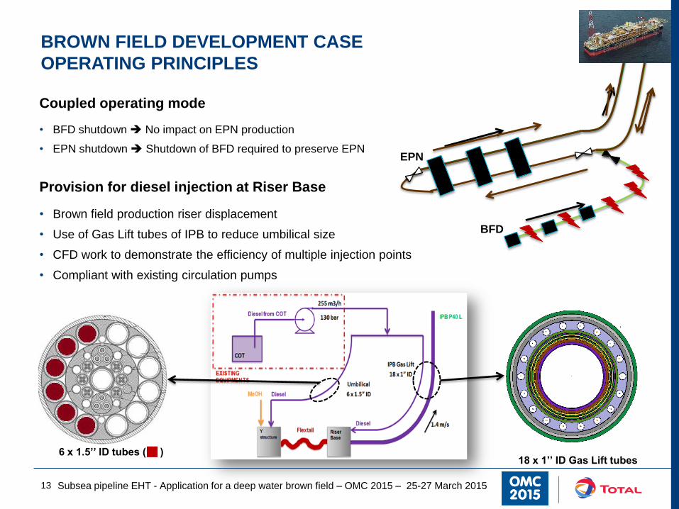
Coupled operating mode
• BFD shutdown No impact on EPN production
• EPN shutdown Shutdown of BFD required to preserve EPN
Provision for diesel injection at Riser Base
• Brown field production riser displacement
• Use of Gas Lift tubes of IPB to reduce umbilical size
• CFD work to demonstrate the efficiency of multiple injection points
• Compliant with existing circulation pumps
Subsea pipeline EHT - Application for a deep water brown field – OMC 2015 – 25-27 March 2015 13
BROWN FIELD DEVELOPMENT CASE
OPERATING PRINCIPLES
6 x 1.5’’ ID tubes ( ) 18 x 1’’ ID Gas Lift tubes
EPN
BFD
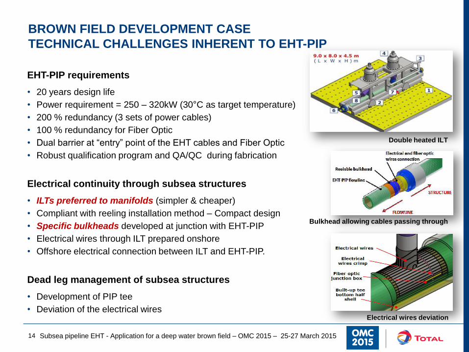
EHT-PIP requirements
• 20 years design life
• Power requirement = 250 – 320kW (30°C as target temperature)
• 200 % redundancy (3 sets of power cables)
• 100 % redundancy for Fiber Optic
• Dual barrier at “entry” point of the EHT cables and Fiber Optic
• Robust qualification program and QA/QC during fabrication
Electrical continuity through subsea structures
• ILTs preferred to manifolds (simpler & cheaper)
• Compliant with reeling installation method – Compact design
• Specific bulkheads developed at junction with EHT-PIP
• Electrical wires through ILT prepared onshore
• Offshore electrical connection between ILT and EHT-PIP.
Dead leg management of subsea structures
• Development of PIP tee
• Deviation of the electrical wires
Subsea pipeline EHT - Application for a deep water brown field – OMC 2015 – 25-27 March 2015 14
BROWN FIELD DEVELOPMENT CASE
TECHNICAL CHALLENGES INHERENT TO EHT-PIP
Double heated ILT
Electrical wires deviation
Bulkhead allowing cables passing through

Extensive Flow Assurance and process studies
• Subsea tie in
– BFD production sent to existing separator
– Topsides modules removal Weight saving
• Change of operating philosophy Water carry
over mode
– Produced water outlet bottleneck with BFD
– Limited topsides work / upgrades
Dedicated dynamic Flow Assurance studies
• Definition of slugging propensity of each production lines
• Check that slugs observed comply with surge volume in the MP separator
Base Case: 1600 tons Subsea Tie In: 250 tons
0.0
10.0
20.0
30.0
40.0
50.0
60.0
70.0
Surg
e v
olu
me
(m
3)
Production year (-)
Total surge volume in the MP separator - Contribution of the different production lines
P50 - Zinia Production line
P40 - Right Branch66m3
Subsea pipeline EHT - Application for a deep water brown field – OMC 2015 – 25-27 March 2015 15
BROWN FIELD DEVELOPMENT CASE
IMPACT ON TOPSIDES

Grouted tee for Water injection
• Water injection riser removal
Significant cost savings (no topsides modifications)
Why tie-in in vicinity at riser base ?
• Optimum with regard to
– Pressure drop in injection network
– THP requirements at Well head
– Existing injection pumps capabilities
Specific offshore operations to install the grouted tee
• Hot tapping drilling operations
• Deployment of subsea structure to support injection line and accommodate grouted tee and isolation valves
Subsea pipeline EHT - Application for a deep water brown field – OMC 2015 – 25-27 March 2015 16
BROWN FIELD DEVELOPMENT CASE
SUBSEA ARCHITECTURE – INJECTION NETWORK
BROWN FIELD DEVELOPMENT CASE
A SOLUTION WITH SIGNIFICANT COST SAVINGS
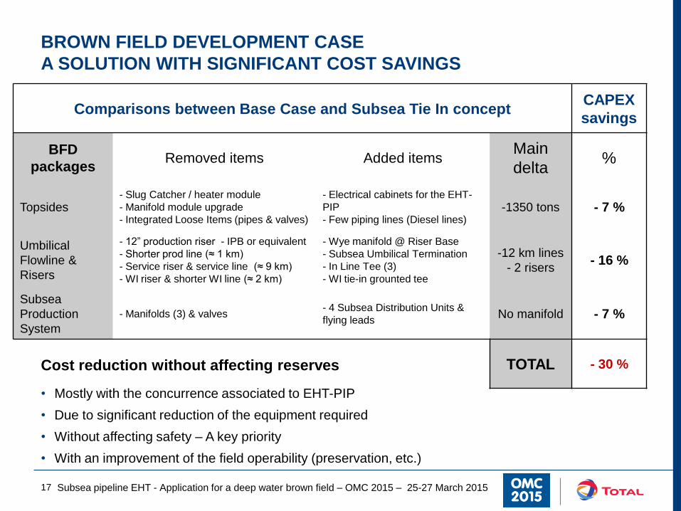
Comparisons between Base Case and Subsea Tie In concept CAPEX
savings
BFD
packages Removed items Added items
Main
delta %
Topsides - Slug Catcher / heater module
- Manifold module upgrade
- Integrated Loose Items (pipes & valves)
- Electrical cabinets for the EHT-
PIP
- Few piping lines (Diesel lines) -1350 tons - 7 %
Umbilical
Flowline &
Risers
- 12” production riser - IPB or equivalent
- Shorter prod line (≈ 1 km)
- Service riser & service line (≈ 9 km)
- WI riser & shorter WI line (≈ 2 km)
- Wye manifold @ Riser Base
- Subsea Umbilical Termination
- In Line Tee (3)
- WI tie-in grounted tee
-12 km lines
- 2 risers - 16 %
Subsea
Production
System
- Manifolds (3) & valves - 4 Subsea Distribution Units &
flying leads No manifold - 7 %
TOTAL - 30 % Cost reduction without affecting reserves
• Mostly with the concurrence associated to EHT-PIP
• Due to significant reduction of the equipment required
• Without affecting safety – A key priority
• With an improvement of the field operability (preservation, etc.)
17 Subsea pipeline EHT - Application for a deep water brown field – OMC 2015 – 25-27 March 2015

CONCLUSION
18 Subsea pipeline EHT - Application for a deep water brown field – OMC 2015 – 25-27 March 2015

CONCLUSIONS (1/2)
Active heating technologies
• Direct Electrical heating
– Field proven solution – Important track record
– High power requirement – Low efficiency
• EHT - PIP
– Feasibility fully demonstrated World’s first EHT-PIP installed on Islay
– Low power requirement – High efficiency
Future developments
• Driven by minimization of CAPEX investments
• Active heating systems can contribute Step changers
• EHT-PIP as a promising solution Simplification of subsea development and operations
EHT-PIP to improve production line operability
• Temperature monitoring with Fiber Optic
• Access to liquid hold-up during production shutdown
• Remediation mean in case of hydrate plug
19 Subsea pipeline EHT - Application for a deep water brown field – OMC 2015 – 25-27 March 2015
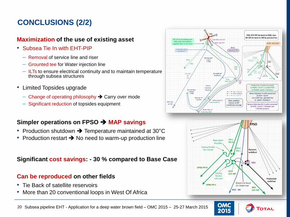
CONCLUSIONS (2/2)
Maximization of the use of existing asset
• Subsea Tie In with EHT-PIP
– Removal of service line and riser
– Grounted tee for Water injection line
– ILTs to ensure electrical continuity and to maintain temperature through subsea structures
• Limited Topsides upgrade
– Change of operating philosophy Carry over mode
– Significant reduction of topsides equipment
Simpler operations on FPSO MAP savings
• Production shutdown Temperature maintained at 30°C
• Production restart No need to warm-up production line
Significant cost savings: - 30 % compared to Base Case
Can be reproduced on other fields
• Tie Back of satellite reservoirs
• More than 20 conventional loops in West Of Africa
20 Subsea pipeline EHT - Application for a deep water brown field – OMC 2015 – 25-27 March 2015

Daily Technical Short Sessions at the Total Stand
21 Subsea pipeline EHT - Application for a deep water brown field – OMC 2015 – 25-27 March 2015