subsea instrumentation interface standardization in the ... · pdf fileicc 2006 can in...
TRANSCRIPT

iCC 2006 CAN in Automation
08-13
Subsea instrumentation interface standardization in the offshore oil and gas industry
David Saul; BP Exploration Operating Co Ltd - EPTG Offshore Systems Team, Sunbury UK
The adoption of the CANOPEN fault tolerant standard by the Subsea Instrumentation Interface Standardisation (SIIS) Joint Industry Project was agreed by the SIIS panel in November 2005 . This paper presents the aims and background to the SIIS working groups decision to adopt CAN as an interface standard. For those with limited knowledge of subsea controls technology used in the offshore oil industry, the paper also provides an overview of the history and challenges of the application. The paper will then go on to discuss in more detail how CAN is being used in SIIS applications, it concludes by looking forward at planned future SIIS milestones.
1 What is SIIS ?
SIIS (Subsea Instrumentation Interface Standardisation) is a joint industry partnership (JIP) with a goal of moving towards an open standard for subsea instrumentation. Achieving this goal will result in subsea-mateable interfaces (as used in subsea control systems), which do not require pre-definition in terms of the instrumentation to which they will subsequently be attached. Figure one gives an indication of a typical subsea development (in this case based around the Marlin tension leg platform). This paper describes the background and drivers for standardisation of subsea control instrumentation interfaces. It then details the process that led to CAN being adopted as the fieldbus standard for digital sensors within SIIS. The paper concludes with some preliminary details on how a practical SIIS interface based on CAN fault tolerant might be implemented together with the future aims of the SIIS group. 2 Background
The drive to find oil offshore started over 90 years ago, initial developments offshore were basic with onshore equipment simply being put on shallow water barges. As developments moved to deeper waters in the Gulf of Mexico and North sea, purpose designed platforms were needed. To improve the economics of developments there was a push to ‘tie-
back’ reservoirs located remotely from the platform.
As offshore development progressed the distances between platform and reservoir increased to the point where some form of remote control was needed. The first systems were based around simple hydraulic control with little or no telemetry. Figure 2 show’s a typical block diagram for such a system.
Figure 1: Typical subsea development
SIIS logo

iCC 2006 CAN in Automation
08-14
As the complexity of these first subsea developments increased it became impractical to continue simply ‘scaling’ the hydraulic systems and the first ‘mulitplex electro-hydraulic control systems’ (E/H controls for short) came into being. Figure 3 shows a typical block diagram for a simple E/H control system.
Instrumentation associated with such systems was still based around analogue sensors adapted from land based petro-chemical use. In the early 90s the specialist gauges used to measure pressure and temperature in the reservoir (typically referred to as downhole gauges) started a move to digital communications, increasing the accuracy available to the user. There was however, no agreed way to interface these devices into the control
system. The outcome was that suppliers simply developed a range of bespoke interfaces - and oil companies picked up the bill and schedule impact for the resulting interface development. With the advent of more advanced downhole technology it was clear that the industry needed a standard to bring together existing downhole gauging systems and the emerging intelligent well control systems. A JIP was formed including oil companies, downhole and control suppliers. The result after much work is the Intelligent Wells Interface Standard (IWIS) documented as an appendix to ISO 13628-6. (Petroleum and natural gas industries – Design and operation of subsea production systems Part 6 Subsea production control system) This is the main defining specification for the industry. During work on the ISO standard submission representatives from BP and Shell noted that whilst there had been focus on downhole equipment, a parallel activity was needed to avoid similar problems with other sensor packages being interfaced to E/H control systems, and the SIIS group was born. Learning from the difficulties of the early IWIS days, the group quickly established a number of sensor interface levels, Level 1, 4-20mA Level 2, simple serial Level 3, configurable and downloadable Level 4, plug and play Level 5, Transparent (future not worked to date)
After discussion levels 2 & 3 were combined with 4 to leave levels 1,4 & 5. Over the last 2 years work has focused on the level 4 standard which covers the majority of digital instruments now connected to E/H control systems.
3 What makes us special?
It is worth detailing at this point what it is that makes the subsea controls systems special. In control and telemetry ‘complexity’ terms they are simple, in many ways primitive. What sets them apart from typical industrial control
Figure 3: Simple E/H control system
Figure 2: Typical system
iCC 2006 CAN in Automation
08-15
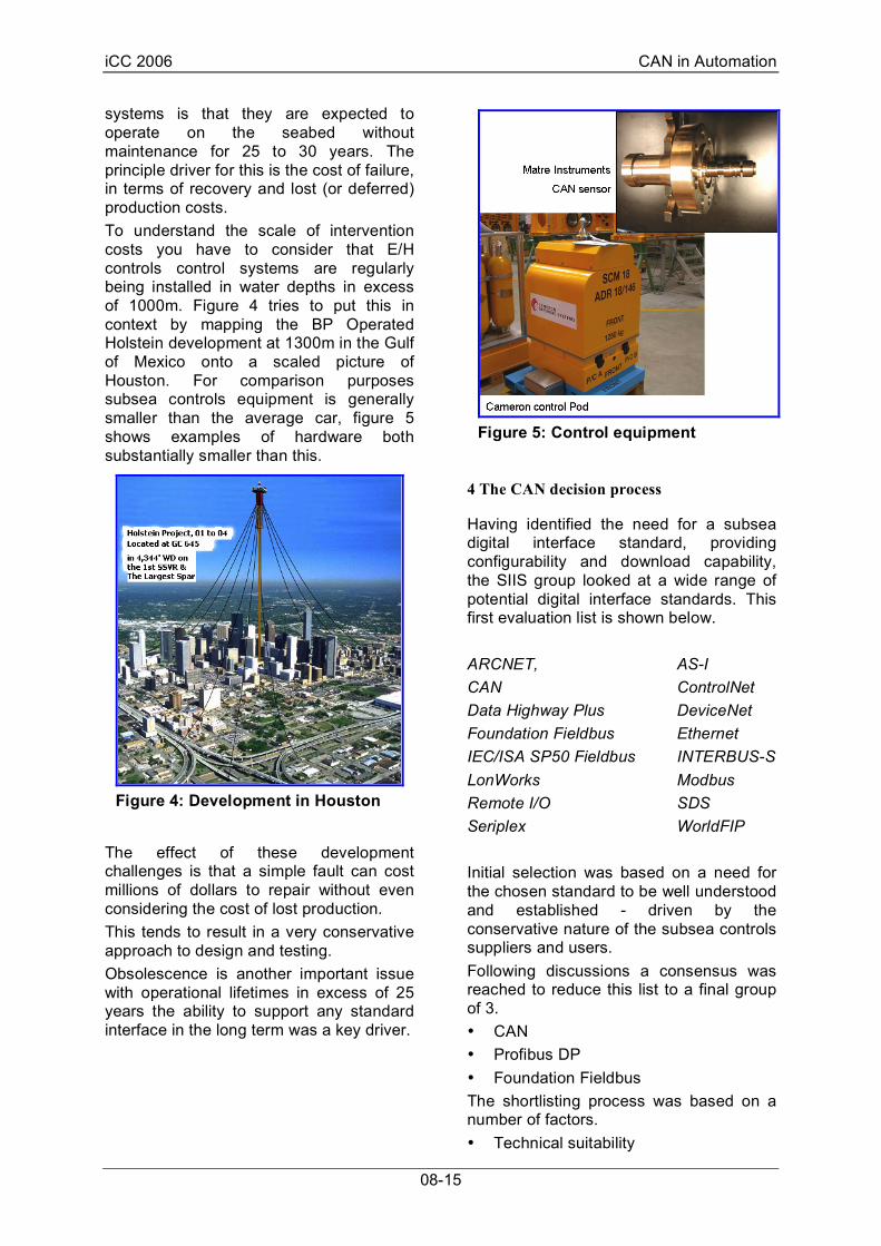
systems is that they are expected to operate on the seabed without maintenance for 25 to 30 years. The principle driver for this is the cost of failure, in terms of recovery and lost (or deferred) production costs. To understand the scale of intervention costs you have to consider that E/H controls control systems are regularly being installed in water depths in excess of 1000m. Figure 4 tries to put this in context by mapping the BP Operated Holstein development at 1300m in the Gulf of Mexico onto a scaled picture of Houston. For comparison purposes subsea controls equipment is generally smaller than the average car, figure 5 shows examples of hardware both substantially smaller than this.
The effect of these development challenges is that a simple fault can cost millions of dollars to repair without even considering the cost of lost production. This tends to result in a very conservative approach to design and testing. Obsolescence is another important issue with operational lifetimes in excess of 25 years the ability to support any standard interface in the long term was a key driver.
4 The CAN decision process
Having identified the need for a subsea digital interface standard, providing configurability and download capability, the SIIS group looked at a wide range of potential digital interface standards. This first evaluation list is shown below. ARCNET, AS-I CAN ControlNet Data Highway Plus DeviceNet Foundation Fieldbus Ethernet IEC/ISA SP50 Fieldbus INTERBUS-S LonWorks Modbus Remote I/O SDS Seriplex WorldFIP Initial selection was based on a need for the chosen standard to be well understood and established - driven by the conservative nature of the subsea controls suppliers and users. Following discussions a consensus was reached to reduce this list to a final group of 3. • CAN • Profibus DP • Foundation Fieldbus The shortlisting process was based on a number of factors. • Technical suitability
Figure 5: Control equipment
Figure 4: Development in Houston

iCC 2006 CAN in Automation
08-16
• Acceptability to SIIS members • Support • Specification management Modbus for instance was dropped on the basis of poor specification management while WorldFIP was considered too complex for the application. Representatives from the user groups representing each of the three standards were offered the opportunity to present technical aspects of their respective fieldbus. This also gave the chance for them to make arguments to support the selection. During this process a decision was taken to focus on the fault tolerant version of CAN. The attraction of the fault tolerant version being the potential to continue to operate with a partial fault on the system. Given the cost of intervention discussed earlier this was seen as an important capability. The SIIS group also considered the ‘cost of ownership’ of each protocol on the shortlist. This was of particular importance to smaller SIIS members who wanted to avoid large cost of entry and maintenance costs of any agreed standard. In comparing the protocol costs the following areas were considered. • s/w & h/w development tool costs • development and production licensing /
IP costs • solution specific component costs i.e.
cost of custom fieldbus interface IC’s The availability of and number chip suppliers supporting each protocol was also assessed. • The conclusions from this work were: • There is an acceptable level of support
for all three fieldbus types • CAN is the most widely supported from
a physical layer viewpoint • Foundation Fieldbus is the most
expensive from a development view point
• Given the low volume high value nature of subsea equipment the cost of actual fieldbus interface hardware is NOT a major driver.
• While all three standards are nominally ‘open’ it is difficult to avoid some
ownership costs, with CAN having the lowest cost , Foundation the highest.
Based on this information the SIIS group took the decision to adopt CANbus (fault tolerant – ISO 11898-3), as the standard for the SIIS level 4 protocol. From the BP perspective the key arguments in favour of CANbus were: • Wide and long term industry support • Acceptance by the majority of controls
vendors • The potential for additional system
availability from the fault tolerant feature
• Relatively low cost of entry for instrument suppliers
5 Practical implementation of a SIIS level 4 CAN based interface
Having decided on a fieldbus standard the next task was to understand how it should be implemented to best effect within the context of a subsea controls system. For instance, a basic CANbus implementation allows 32 nodes (fault tolerant), but to have this number of sensors connected to a single line in a system installed subsea creates an unacceptable reliability risk. Discussions within the SIIS group have suggested a maximum of 4 sensors connected to a single external CAN loop is probably the largest number that oil companies would accept currently. From a standardisation viewpoint this also allows SIIS to define that all SIIS compliant sensors should be fitted with a 500Ohm resistor to provide basic termination. Thus sensor suppliers need only produce a single variant sensor (remember changing a termination resistor value is not easy on a sensor designed to operate in 3000m of water). Also controls vendors know external networks will always be terminated within the 500-100Ohm range. In addition there is a need to understand how the network should be connected physically. Figure 6, shows 3 potential options for a simple 4 node sensor network.

iCC 2006 CAN in Automation
08-17
In option ‘A’ a simple daisy chain approach is used, this is the cheapest to implement but is unattractive from a reliability viewpoint. The second mitigates this by opting for a star connection point within the relative safe environment of the subsea control module (SCM). This option unfortunately requires more connectors which has an effect on cost (a typical subsea connector can cost in excess of €2500). The additional connectors also use valuable real estate on the SCM. Option C is likely to be the preferred option for multiple sensors it has the advantage of keeping connections in the SCM to a minimum while avoiding single point failures at the sensor connection (which is historically the biggest risk point). It also has the advantage that ‘y’ splices are commonly used for sensor connections subsea, minimising the perceived level of ‘new’ design. Ruling out option A for SIIS connected sensors also makes pin allocation easier. Based on this the SIIS group has decided to opt for an 4 pin connector with any screen being taken via the connector
body, following the pin allocation shown in table 1.
Table 1
Pin Allocation
1 CAN High
2 Ground
3 CAN Low
4 Sensor Power
body Screen - optional Notes 1) core pairs 1,3 and 2,4 to be twisted wherever possible 2) pin allocations to be formally agreed by SIIS-JIP 10/06
The screen connection is considered optional because the nature of applications subsea removes much of the need to consider screening against radiated noise. The group has also spent time considering how best to take best advantage of the fault tolerant capabilities of the CAN variant chosen. As discussed the decision to go fault tolerant was based on the ability for continued operation under some fault conditions. This is particularly important in environments where it is difficult or impossible to access the subsea equipment during certain times. A good example of this in the future will be the Arctic regions where pack ice may preclude surface based maintenance for up to six months of the year. Figure 7 shows an artists impression of what a subsea Arctic development might look like.
Building on this it is also important to know that a fault exists, but with diagnostic availability varying between chip sets the
Figure 6: Three options for a four nodes sensor network
Figure 7: Subsea arctic development

iCC 2006 CAN in Automation
08-18
group has decided to mandate only the minimal fault reporting capability. Although this reduces the available ‘fault knowledge’ it does substantially increase the number of CAN fault tolerant devices available for companies developing SIIS compliant devices. The opportunity to include for more complex reporting (as provided by the Philips chipsets) is left a supplier option.
6 Planned SIIS-JIP work
There is obviously much work still to do for the SIIS JIP group. With subsea controls contracts starting to quote SIIS compliant interfaces the most pressing issue is to agree the key hardware aspects of the level 4 interface. This is of particular relevance to BP as contracts have recently been places for the Taurt development in the Nile delta specifying SIIS interfaces for a number of sensor types. The longer term goal for the SIIS group is to gain agreement from ISO for the inclusion of the standard in the next revision of ISO13628-6. It is hoped SIIS ‘make’ the next revision round which will start in 2-3 years time. To conclude work on SIIS is moving quickly, the group has learnt from difficulties faced by the IWIS JIP Commercially and technically. The adoption of CAN is popular with suppliers, removing the need to design and support multiple digital interfaces for subsea sensor products. From the oil company perspective standardisation provides for improved system reliability together with a combination of access to more mature technology and de-linking of the controls system sensor/Instrumentation purchases. The SIIS JIP website can be found at www.SIIS-JIP.com, full member and contact details can be found here. 7 Acknowledgements
The author would like to acknowledge the following and organisations for support in producing this paper.
Cameron Controls (www.c-a-m.com) FMC technologies (www.fmctechnologies.com) GE Sensing (www.gesensing.com) Matre Instruments (www.matreinstruments.com) OTM consultants (www.otmnet.com)