study unit manufacturing processes, part 2
TRANSCRIPT

Study Unit
ManufacturingProcesses, Part 2By
Thomas Gregory

Manufacturing is the process of using raw materials, energy,labor, and specific processes to produce goods either for con-sumption directly by the end user, or else for incorporation intomore complex products. In the previous unit, you learnedabout significant technical developments that shaped ourpresent-day manufacturing industry. In this unit you’ll learnabout the raw materials used for manufacturing products.Natural elements, mixtures, and compounds form the basisof most products manufactured today, but artificially manu-factured or engineered materials are becoming more importantto the manufacturing environment and the products we useevery day.
In this unit you’ll learn about how materials are classified,how they’re produced and optimized for use in manufacturingapplications, and how some materials perform better in cer-tain applications than others. Indeed, the choice of materialsoften determines the basic manufacturing techniques thatcan be used, as well as the viability of a process or product.The ongoing evolution of new materials has driven the direc-tion of the manufacturing industry. Modern automobiles nowhave more plastic components than steel, and modern mili-tary aircraft are possible only through the use of engineeredmaterials called composites that combine high strength andlow density. Materials selected for a component will deter-mine the basic manufacturing processes and sequences usedto produce the product. These in turn will determine the finalcost and profitability of the part or product produced.
iii
Previe
wPrevie
w

Previewiv
When you complete this study unit, you’ll beable to
• Describe the four basic classifications of materials usedfor manufacturing processes
• Understand the essential metallurgical characteristics of steel and ferrous alloys, and types of steel for different applications
• List the important properties of nonferrous alloys
• Explain the effect material choices have on the subse-quent manufacturing processes and the performance ofthe end product
• Describe the manufacturing processes for ceramics,polymers, and composite materials especially as theyrelate to metal and alloy replacement applications

MATERIAL FUNDAMENTALS 1
Atomic Structure 2The Four Classes of Materials 5
MATERIAL PROPERTIES 9
Physical Properties 10Mechanical Properties 18Material Properties Summary 40
METALLIC MATERIALS FOR MANUFACTURING 43
Classification of Metals 45Steel 54Aluminum 66Copper 68Zinc Alloys 69
NONMETALLIC MATERIALS FOR MANUFACTURING 71
Ceramics 71Polymers 77Composites 87
SELF-CHECK ANSWERS 99
EXAMINATION 101
v
Contents
Contents
1
MATERIAL FUNDAMENTALS
All manufactured products start with raw materials. Fromthe earliest stone tools to the latest spacecraft, the first stepin the manufacturing process is to secure the raw materialsnecessary to make the product effectively and efficiently.Choosing an effective material involves selecting a materialthat will give an acceptable level of performance; an efficientmaterial is one that allows normal manufacturing processes tomake the part at minimum cost. Many products can be madeout of more than one type of material, but the choice of mate-rial can have dramatic effects on their performance. For example,baseball bats and golf club heads can be made out of wood,as they were in the past. However, the change to aluminumhas significantly improved the products’ performance, becausealuminum is harder and has a higher coefficient of restitutionthan wood. Simply put, golf balls and baseballs travel fartherwhen hit with aluminum clubs and bats. Many factors deter-mine the effectiveness and efficiency of a material, includingthe cost and the types of processes that must be used tomanufacture the product from a specific material. In the caseof the baseball bats and golf clubs, cost-effective manufactur-ing processes for using aluminum in these applicationsweren’t available when the sports were invented.
Manufacturing Processes,Part 2

Manufacturing Processes, Part 22
Atomic Structure
All the manufacturing materials we start with have character-istics and properties that make them what they are: soft,hard, transparent, light, heavy, metals, gaseous, brittle,strong, and so on. But what determines why they’re thatway? The short answer is that the characteristics of anymaterial are determined by how the atoms of an elementbond with each other and with other atoms. A useful way toimagine atomic structure is to think of atoms as a centralnucleus surrounded by electrons. The nucleus is composed ofpositively charged protons and neutrally charged neutrons.Each element in the atomic chart has a specific atomic number, which is the number of protons in that element. For each proton in the nucleus there’s an electron orbiting in an outer shell, making the overall net charge of the atom neutral. As the number of electrons increases, the atombecomes larger and its chemical properties change based onthe number of outermost electrons, called valence electrons.Figure 1 shows a schematic diagram of the positions ofvalence electrons.
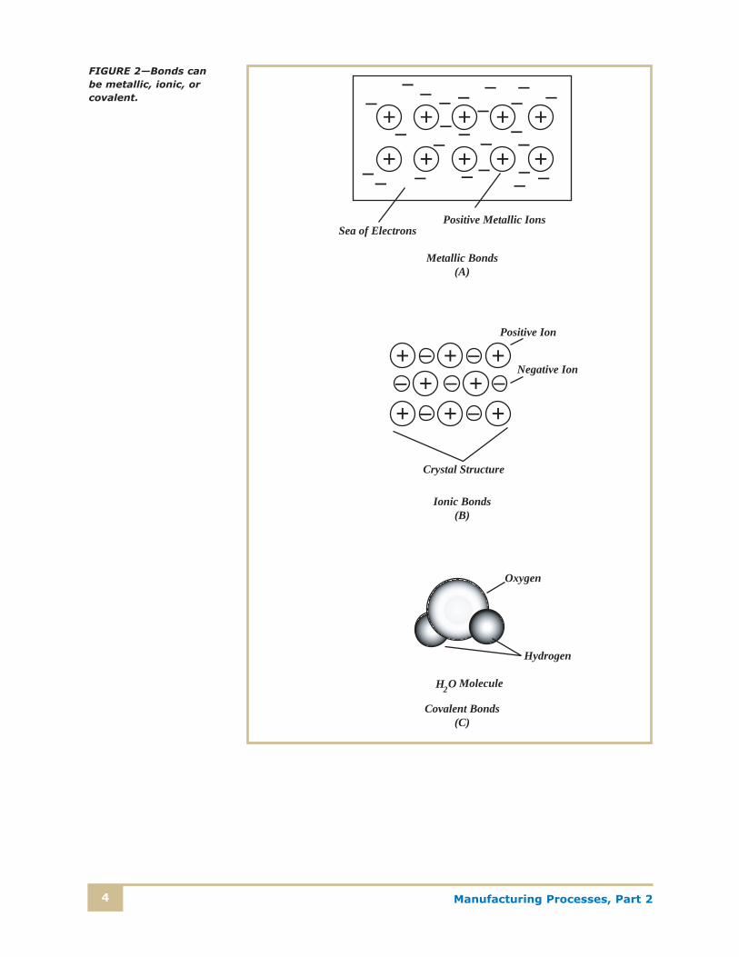
The valence electrons of an atom determine the chemicalproperties of that element as well as how it will combine withother elements. The maximum number of electrons any ele-ment can have in its outer orbit is eight. (The reason for thisis complex, and not entirely understood.) Some materials mayhave only one or two electrons, and they tend to give them upeasily to other elements that have six or seven electrons. In thiscase, the gain or loss of electrons produces ions—positively or negatively charged atoms—that tend to form ionic bonds.Positive ions have a strong attraction to negative ions andthus the two tend to stick together. Metals have a type ofionic bond that’s strong, but the positive metallic ions withintheir crystal structure can be shifted without breaking thebonds. This is why metals can be bent and deformed withoutbreaking. Covalent bonds are bonds between two or moreatoms that share valence electrons more equally—betweentwo atoms that have four outer electrons, say. Covalentbonds are strong and stable, and tend to be harder to breakthan ionic bonds. Gases such as oxygen and nitrogen tend toform covalent bonds with themselves and other materials.Figure 2 shows examples of these types of bonds.

Manufacturing Processes, Part 2 3
Metallic, covalent, and ionic bonds are primarily responsi-ble for the way materials behave—whether they’re metals, nonmetals, or gases to start with, and whether they becomemetals, ceramics, or plastics after they combine with otherelements. Also, depending on the elements and the conditions,elements can be mixed together, forming mixtures, or alloys.Materials can combine chemically to form stable compounds.For example, iron can be mixed with carbon to form the alloysteel, but under the right conditions, iron will also form thechemical compound iron carbide (Fe3C), a very hard, strong,and brittle material.
1 Electron
6 Neutrons
6 Electrons
6 Protons
Hydrogen (A)
Carbon(B)
1 Proton
FIGURE 1—The valenceelectrons determine howatoms bind with similarand different atoms toform chemical compoundsand mixtures. Each typeof atom has an equalnumber of protons andelectrons unless it hascombined with otheratoms to share thevalence electrons.
Manufacturing Processes, Part 24
+
+
+
+
+
+
+
+
+
+–
Sea of ElectronsPositive Metallic Ions
+ + ++ +
+ + +
Positive Ion
Negative Ion
Crystal Structure
Hydrogen
Oxygen
H2O Molecule
Metallic Bonds(A)
Ionic Bonds(B)
Covalent Bonds(C)
– – –––
–––
–
––
– – –– –
– ––
––– –
–
– ––– –
– –
FIGURE 2—Bonds can be metallic, ionic, orcovalent.
Manufacturing Processes, Part 2 5
The Four Classes of Materials
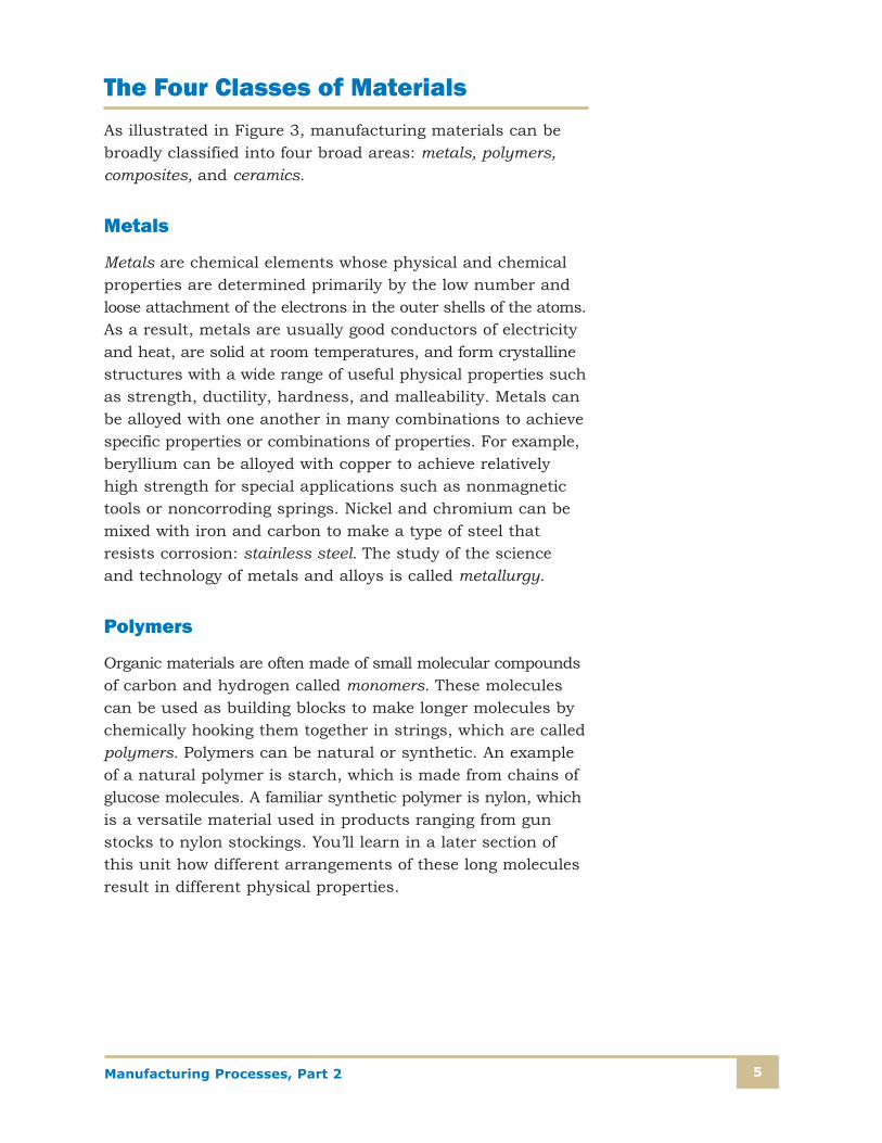
As illustrated in Figure 3, manufacturing materials can bebroadly classified into four broad areas: metals, polymers,composites, and ceramics.
Metals
Metals are chemical elements whose physical and chemicalproperties are determined primarily by the low number andloose attachment of the electrons in the outer shells of the atoms.As a result, metals are usually good conductors of electricityand heat, are solid at room temperatures, and form crystallinestructures with a wide range of useful physical properties suchas strength, ductility, hardness, and malleability. Metals canbe alloyed with one another in many combinations to achievespecific properties or combinations of properties. For example,beryllium can be alloyed with copper to achieve relativelyhigh strength for special applications such as nonmagnetictools or noncorroding springs. Nickel and chromium can bemixed with iron and carbon to make a type of steel thatresists corrosion: stainless steel. The study of the science and technology of metals and alloys is called metallurgy.
Polymers
Organic materials are often made of small molecular compoundsof carbon and hydrogen called monomers. These moleculescan be used as building blocks to make longer molecules bychemically hooking them together in strings, which are calledpolymers. Polymers can be natural or synthetic. An exampleof a natural polymer is starch, which is made from chains ofglucose molecules. A familiar synthetic polymer is nylon, whichis a versatile material used in products ranging from gunstocks to nylon stockings. You’ll learn in a later section ofthis unit how different arrangements of these long moleculesresult in different physical properties.

Manufacturing Processes, Part 26
Precious Metals
Refractory Metals (Tungsten/Tantalum/Molybdenum)
Ceramics
Electronic Materials (Ferrites/Semiconductors)
Constructional Ceramics (Porcelain/Stoneware/Earthenware)
Natural Ceramics (Stone)
Glasses (Soda/Borosilicates/Pyroceramics)
Engineered Ceramics (Alumina/Carbides/Nitrides)
Material Type
CompositesPolymer Matrix
Ceramic Matrix
Metal Matrix
Carbon-Carbon
Polymers
Thermosets
Partially Crystalline (Polyamides/Acetals/Polyathenes)
Amorphous (PVC/Polycarbonates/Polystyrenes)
Natural Polymers (Cellulose-Based/Protein-Based)
Thermoplastics
Metals
Ferrous Alloys
Plain Carbon Steels
Cast Irons (Grey/White/Malleable/Nodular)
Alloy Steels (Low Alloy/Tool/Stainless)
Nonferrous Alloys
Light Alloys (Zinc/Aluminum/Magnesium/Titanium)
Heavy Alloys (Copper/Nickel/Lead)
Rubbers (Natural/Butyl/Silicones/Nitrile/Styrene)
Epoxies/Phenolics/Aminos/Polyesters/Silicones
FIGURE 3—Manufacturing materials can be generally classified into four general types, with manyvariations within each type.

Manufacturing Processes, Part 2 7
Composites
Composite materials are fabricated from combinations of twoor more materials, such as plastic and glass. A compositeuses one of the materials in a fiber form that’s completelysurrounded by and mixed with a support material called amatrix. The combination allows the best characteristics ofeach material to be maintained in the end material. By usingdifferent combinations of materials, specific desired proper-ties can be obtained. The manufacture of composites is laborintensive, so they tend to be more expensive, but the possi-bilities of obtaining properties such as high strength and lowweight for high-performance applications such as aircraftkeeps interest in these materials high.
Ceramics
Ceramic materials are very stable nonmetallic, inorganic com-pounds mostly of oxygen, but may also include compounds ofcarbon, nitrogen, boron, and silicon. Common ceramic mate-rials are formed from raw materials that are made into thedesired shape in a “green” condition, and then hardened byexposure to heat. The process of making pottery out of clayand firing it in a hot oven was the beginning of the use ofceramic materials. The modern technology of industrialceramics involves developing and making ceramic materialssuitable for a wide range of special applications such as ther-mal and electrical insulators or even dental bridges. Softermaterials can also be coated with thin ceramic films as a surface treatment; anodizing is the process of changing the outer layer of aluminum to a ceramic material called aluminum oxide, which is extremely hard and corrosionresistant, as well as an electrical insulator. The thickness of these coatings is on the order of several thousandths of an inch.

Manufacturing Processes, Part 28
Self-Check 1
At the end of each section of Manufacturing Processes, Part 2, you’ll be asked to pause and
check your understanding of what you’ve just read by completing a “Self-Check” exercise.
Answering these questions will help you review what you’ve studied so far. Please
complete Self-Check 1 now.
Please fill in the correct answer.
1. _______ is/are responsible for the chemical behavior of elements.
2. _______ bonding occurs when positive and negative _______ are attracted to each other.
3. _______ bonds can be deformed without breaking the crystal structure.
4. Two or more metals mixed together to obtain specific material properties are known as a(n) _______.
5. The study of what happens when metals are mixed together is called _______.
6. Materials such as thermal insulators and aluminum oxide are called industrial _______.
Check your answers with those on page 99.
Manufacturing Processes, Part 2 9
MATERIAL PROPERTIES
Selecting the right material for a manufactured product requiresknowledge of how the material will perform in the environmentwhere it’ll be used. Some of the questions you would ask tomake a decision might be the following: What forces will beapplied to the part? How much heat will be required to passthrough the part? Will it be exposed to a corrosive environmentsuch as seawater? The answer to these and other questionswill direct your choice of materials for the parts your productis made from. Once you understand the performance require-ments, you’ll need to study the properties of the materials—metals, ceramics, polymers, and composites—to evaluatetheir likely performance in your application.
Material properties can be divided into two categories, physicalproperties and mechanical properties. Physical properties, likedensity, are the characteristics a material has because of theelements and chemical configuration of which it’s made, andthese characteristics don’t depend on how much material ispresent. Mechanical properties are characteristics that determinehow a material will react to outside forces that cause it to bend,stretch, compress, or break. In the next sections we’ll discussthese properties and the essential elements you’ll need toknow when selecting a material for a specific application.
Pure materials have certain properties that can be modifiedwith the addition of other elements. For example, alloys aredeveloped to have specific properties that are the result of the combination of these elements. Sometimes the additionalelements have desirable effects; at other times, the added elements degrade one property while helping another. Purecopper is one of the best conductors of heat, for example, but pure copper isn’t very strong. Alloying elements such asberyllium, tin, or aluminum are added to increase the cop-per’s strength; however, the thermal conductivity decreasessignificantly. Choosing the best material for a product isoften a case of choosing the least offensive trade-off amongcritical properties.
Manufacturing Processes, Part 210
Physical Properties
As we said before, physical properties are due to the elementspresent in a material and how they’re combined or mixed.These are sometimes called bulk properties. The more impor-tant physical properties we’ll discuss now include density,thermal conductivity, electrical resistivity, specific heat, thermal coefficient of expansion, and melting point.
Density
Density is the amount of mass present in a certain volume of material. The densities of some common engineering materials are shown in Table 1. In the metric system, densityis given in kilograms per cubic meter (kg/m3), or, since theseare large units, grams per cubic centimeter (gm/cm3). In theU.S. Customary System (USCS), density is usually given inpounds per cubic inch (lbs/in.3), or sometimes pounds percubic foot (lbs/ft3). Density will determine how much a partweighs—high-density materials will weigh much more thanlow-density materials. Steel is about three times denser thanaluminum, and a part made of aluminum will obviously weighless than the same part made of steel (though the steel partwill be stronger). Sometimes the lower strength of aluminumcan be overcome by making the part slightly larger in somedimensions, resulting in a part that has strength comparableto steel but is much lighter.
Thermal Conductivity
Thermal conductivity is a measure of how well heat energytravels through a material. It’s primarily a function of thecrystalline structure of the material and how many free elec-trons are present in the crystal structure to carry heat energy.In general, materials that are good electrical conductors arealso good conductors of heat. Machines often generate heatin the form of thermal dissipation, as in motors, or frictionalenergy from rotating bearings or sliding parts. To avoid excessivetemperatures, it’s important that the materials selected be

Manufacturing Processes, Part 2 11
able to conduct this heat away to the air. Thermal conductivityis measured in units of watts per meter per kelvin (W/m-K)in SI and Btu/per hour per foot per degree Fahrenheit(Btu/hr-ft-ºF) in USCS units.
Metals are good conductors of heat, but vary widely in effectiveness: aluminum and aluminum alloys have thermal con-ductivities of about 200 W/m-K, while steels have conductivitiesof about 50 W/m-K. Designers must take these differences
Table 1
DENSITIES OF SOME COMMON MATERIALS
MaterialDensity
gm/cm3
Density
lb/in3
A36 Steel 7.85 .283
304 Stainless Steel 8.00 .289
Aluminum 1100 2.71 0.0978
Copper C11000 8.89 0.321
Titanium Ti-6Al-4V 4.43 0.160
Gold 19.32 0.697
Molybdenum 10.22 0.369
Tungsten 19.3 0.697
Aluminum oxide 3.98 0.144
Concrete 2.4 0.087
Glass ceramic (pyroceram) 2.60 0.0939
Silicon carbide 3.3 0.119
Elastomers—nitrile 0.98 0.0354
Epoxy 1.11–1.40 0.0401–0.505
Phenolic 1.28 0.0462
Polyester 1.05 0.045
Polyethylene (LDPE) 0.925 0.0334
Polystyrene (PS) 1.05 0.0379
Polytetrafluoroethylene (PTFE) 2.17 0.0783
Aramid (Kevlar) 1.44 0.0520
E-glass fibers—epoxy matrix 2.1 0.075
Manufacturing Processes, Part 212
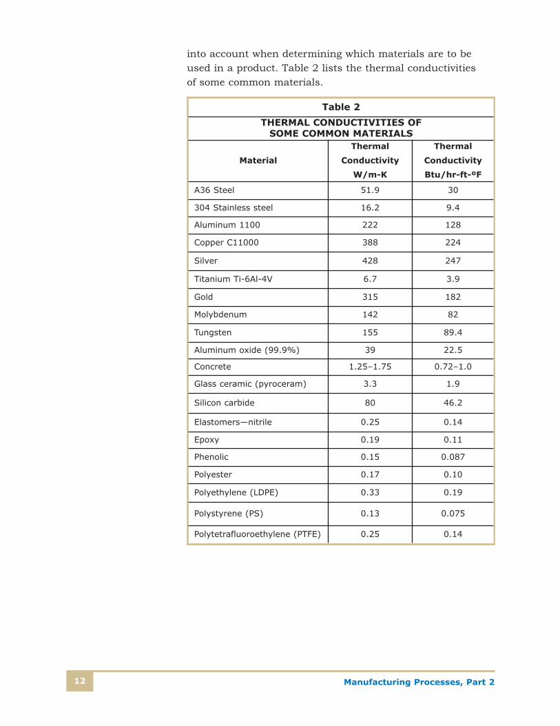
into account when determining which materials are to beused in a product. Table 2 lists the thermal conductivities of some common materials.
Table 2
THERMAL CONDUCTIVITIES OF SOME COMMON MATERIALS
Material
Thermal
Conductivity
W/m-K
Thermal
Conductivity
Btu/hr-ft-ºF
A36 Steel 51.9 30
304 Stainless steel 16.2 9.4
Aluminum 1100 222 128
Copper C11000 388 224
Silver 428 247
Titanium Ti-6Al-4V 6.7 3.9
Gold 315 182
Molybdenum 142 82
Tungsten 155 89.4
Aluminum oxide (99.9%) 39 22.5
Concrete 1.25–1.75 0.72–1.0
Glass ceramic (pyroceram) 3.3 1.9
Silicon carbide 80 46.2
Elastomers—nitrile 0.25 0.14
Epoxy 0.19 0.11
Phenolic 0.15 0.087
Polyester 0.17 0.10
Polyethylene (LDPE) 0.33 0.19
Polystyrene (PS) 0.13 0.075
Polytetrafluoroethylene (PTFE) 0.25 0.14

Manufacturing Processes, Part 2 13
Electrical Resistivity
Electrical resistivity is a measure of how well the materialresists the flow of electric currents. Conversely, conductivityis the measure of how well the material conducts electricity.Metals are usually good conductor of electricity (and heat),but may also be used in applications that call for high mate-rial resistances. For example, the heating elements in electricheaters are often made out of a nickel-chrome alloy callednichrome, which is known for its high resistance. Filamentsin light bulbs are made out of tungsten, which has a fairlyhigh resistivity, but also remains strong when very hot.Tungsten is known as a refractory metal because of its abilityto be used at high temperatures.
The electrical resistance of a wire (or any metal shape) can becalculated using the coefficient of resistivity (�), which has theunits of ohm-meters (�-m). The resistance of a wire in ohmsis given by
R = � � L/A
where R is the value in ohms (�), � is the material resistivityin �-m, L is the length of the wire in meters, and A is thecross-sectional area in square meters (m2).
Examples of resistivity values for some manufacturing mate-rials are shown in Table 3. As the formula indicates, thelonger the path L, the higher the electrical resistance will be.Increasing the area or wire diameter will lower the resistance.Wires used in electrical applications are usually made of cop-per or aluminum, but to carry the same amount of current,aluminum wire needs to be much larger in diameter. Aluminumis used primarily because of its lower weight and its beingsomewhat cheaper than copper.
Manufacturing Processes, Part 214
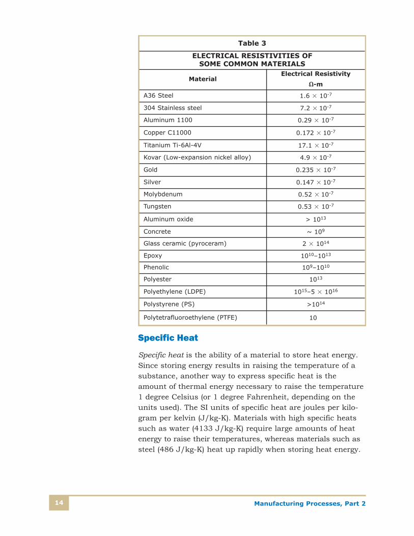
Specific Heat
Specific heat is the ability of a material to store heat energy.Since storing energy results in raising the temperature of asubstance, another way to express specific heat is theamount of thermal energy necessary to raise the temperature1 degree Celsius (or 1 degree Fahrenheit, depending on theunits used). The SI units of specific heat are joules per kilo-gram per kelvin (J/kg-K). Materials with high specific heatssuch as water (4133 J/kg-K) require large amounts of heatenergy to raise their temperatures, whereas materials such assteel (486 J/kg-K) heat up rapidly when storing heat energy.
Table 3
ELECTRICAL RESISTIVITIES OF SOME COMMON MATERIALS
MaterialElectrical Resistivity
��-m
A36 Steel 1.6 � 10-7
304 Stainless steel 7.2 � 10-7
Aluminum 1100 0.29 � 10-7
Copper C11000 0.172 � 10-7
Titanium Ti-6Al-4V 17.1 � 10-7
Kovar (Low-expansion nickel alloy) 4.9 � 10-7
Gold 0.235 � 10-7
Silver 0.147 � 10-7
Molybdenum 0.52 � 10-7
Tungsten 0.53 � 10-7
Aluminum oxide > 1013
Concrete ~ 109
Glass ceramic (pyroceram) 2 � 1014
Epoxy 1010–1013
Phenolic 109–1010
Polyester 1013
Polyethylene (LDPE) 1015–5 � 1016
Polystyrene (PS) >1014
Polytetrafluoroethylene (PTFE) 1017

Manufacturing Processes, Part 2 15
Water is an unusual substance in many ways, with the abili-ty to store large amounts of thermal energy being one reasonthat it’s used extensively as a cooling agent for equipment thatgenerates a lot of heat, such as internal-combustion motors.
Thermal Coefficient of Expansion
Thermal coefficient of expansion is a measure of how much amaterial expands when heated. Almost every material growsin its linear dimensions as its temperature increases. Sincevolume is a function of those dimensions and since the massdoesn’t change with temperature, it follows that as tempera-ture increases, the density of an object or part will decrease.More importantly, changes in dimensions can severely affectproduct performance if the changes aren’t accounted for inthe design: moving shafts can bind, transmitted forces candamage other parts, and protective seals can break. Partsbeing assembled by brazing or welding, as well as any subse-quent heat treatments, must account for thermal expansion,as the thermal stresses that result from too rapid heating orcooling can damage parts.
The amount of thermal expansion can be calculated by usingthe material’s coefficient of thermal expansion (k), which hasunits of meters per meter per Celsius degree, or inches perinch per Fahrenheit degree, depending on which units you’reusing. The change in length (or the change in any lineardimension) is given by
�L = k � L × �T
where k is the thermal coefficient of expansion, L is the length,and �T is the temperature difference, or the final temperatureminus the initial temperature.
An example will clarify how this calculation is done and howimportant thermal expansion is. Suppose a steel beam to beused in a bridge is manufactured in Pennsylvania in July.Just before shipment, the beam is measured to be exactly 24feet (288.00 inches) long. The temperature that day is 90ºF.The beam is shipped to Maine, where it’s assembled into abridge in January, on a day when the temperature is 20ºF.What is the length of the beam when it’s installed?

Manufacturing Processes, Part 216
Solution: Note that the temperature is decreasing. This meansthat temperature difference will be a negative value, and thematerial will be getting shorter as the temperature decreases:20 – 90 = –70ºF. From Table 4, the thermal expansion coeffi-cient of steel (A36 alloy) is about 6.5 � 10-6 in./in./ºF. �L = 6.5 � 10-6 in./in./ºF � 288 in. � ( –70ºF) = –0.13104 in.
Table 4
COEFFICIENTS OF EXPANSION OF SOME COMMON MATERIALS
Material
Coefficient of
Thermal
Expansion—
10-6/ºC
Coefficient of
Thermal
Expansion—
10-6/ºF
A36 Steel 11.7 6.5
304 Stainless steel 17.2 9.6
Aluminum 1100 23.6 13.1
Copper C11000 17.0 9.4
Titanium Ti-6Al-4V 8.6 4.8
Gold 14.2 7.9
Molybdenum 4.9 2.7
Tungsten 4.5 2.5
Aluminum oxide 7.4 4.1
Concrete 12.0 6.2
Glass ceramic (pyroceram) 6.5 3.6
Silicon carbide 4.6 2.6
Elastomers—nitrile 235 130
Epoxy 95 55
Phenolic 122 68
Polyester 130 80
Polyethylene (LDPE) 180–400 100–220
Polystyrene (PS) 90–150 50–83
Polytetrafluoroethylene(PTFE) 126–216 70–120
Aramid (Kevlar)LongitudinalTransverse
–2.060
–1.133
E-glass fibers—epoxy matrixLongitudinalTransverse
6.630
3.716.7
Manufacturing Processes, Part 2 17
In other words, the change in temperature caused the beamto shrink over 1/8 of an inch. This may not seem like much,but if the beam is bolted or welded in place, the stress on the joints of the structure would be tremendous. Repeatedcycles of heating and cooling can cause parts to crack due to temperature cycling.
Melting Point
The melting point of a material is the point at which a solid changes into a liquid. For pure substances, this is asingle, specific temperature. Pure copper melts at 1083ºC, for example. However, metal alloys don’t have a single meltingpoint temperature, because of the addition of materials thathave different melting points. Instead, they melt over a rangeof temperatures. The phase during the period in which it firststarts to turn to liquid until it’s completely liquefied is calleda mush, and contains both solid and liquid portions duringthe transition.
Exact knowledge of melting points is needed when joiningmaterials by brazing, where two or more parts are joined byplacing a lower-melting-point material between them, raisingthe temperature of the assembly to just above the meltingpoint of the braze material, and then cooling the assembly.Multiple braze joints can be made by using a sequence oflower-melting-point materials in separate runs.
For example, two steel parts could be brazed together withcopper (melting point 1083ºC), and additional steel partscould be added and brazed to this assembly with anotherbraze run using gold (melting point 1064ºC). The design of thebraze joints between two or more materials, and the fixturesused to hold them during the braze cycle, must account forany difference in expansion rates of the materials.
Material properties are greatly affected long before the melting point is reached. In fact, some materials like glassdon’t even have a well-defined melting point. Annealing,the process of softening a material, is done by raising its temperature to a point above room temperature but wellbelow the melting point, or the point where metallurgical
Manufacturing Processes, Part 218
changes can take place. For steel, this temperature is in therange of 1400ºF depending on its composition, particularly itscarbon content.
All the characteristics discussed so far are properties of thebulk material; that is, they don’t depend on the amount ofmaterial present. If a part is made out of steel, all the physi-cal properties of steel will be applicable to the part regardlessof its shape, size, or configuration. In the next section we’lldiscuss how materials respond to applied forces, where thesize and shape of the part have a significant effect on how it performs.
Mechanical Properties
Long before the manufacturing process begins, engineers willgenerate a list of materials that are suitable for the productionof the part, and they’ll consider how solid materials respondto applied forces that may try to pull, push, bend, or twistthe product out of shape. They’ll also determine how easily a part can be made from a certain material, and may alsoconsider alternatives based upon ease of manufacture.
Materials are made of atoms bound together to form a solid,and applied forces try to break, or at least move, these bonds.If the bonds are made to move, the material deforms; if thebonds are made to break, the material cracks and fails.
To understand how materials are selected based on theirresponse to outside forces, you must understand some of theconcepts that define a material’s strength. All materials moveunder the influence of forces, even if only microscopically.Everything acts to some extent like a spring, and if you pullor push on it, it will move. How much it moves will depend onthe principal elements of the material, the crystal structure,and the bonds to other elements. The shape of the part andthe material’s resistance to the applied forces will also deter-mine how much movement occurs. For example, a yardstickcan be easily bent across the thin dimension, but is very dif-ficult to bend against the wide, or thick, one. The major fac-tor that determines how any material will respond to externalforces is the material itself, and how it has been preparedduring the manufacturing process.
Manufacturing Processes, Part 2 19
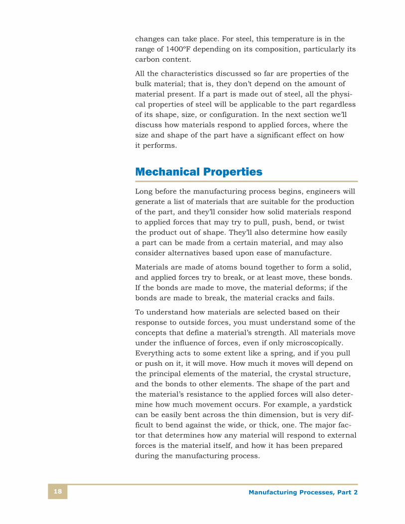
Simple Tensile Stress
Large forces can be applied to a part without it breaking,because failure isn’t a function of the amount of force, butrather the amount of stress produced in the material. Thefirst kind of stress we’ll examine is called tensile stress, whichis a result of a force pulling on a material in one direction.
Figure 4 shows a cable attached to a ceiling with a weight hungon the end. The material in the cable is experiencing tensilestress. Calculating tensile stress in this example is fairly simple.It’s equal to the applied force divided by the area:
� = F/A
where � is the stress, F is the force in pounds, and A is thearea in square inches. You can see that the units of stressare pounds per square inch, or psi. In the metric system, theunits of force are in newtons, the area is in square meters,and stress units are called pascals. A pascal (Pa) is a verysmall unit, so you’re more likely to be working in units ofkilopascals (KPa) or megapascals (MPa).
Weight
Force
Diameter (D)
Area (A)
Tensile Stress = = ForceArea
σ =FA
A = πD 4
2
σ
Cable
FIGURE 4—Tensile stressis applied to this cablesuspending a weight. Thestress is proportional tothe cross-sectional areaof the wire.

Manufacturing Processes, Part 220
Let’s say that a support rod that’s 1/4 inch in diameter sup-ports a weight of 500 pounds suspended from a ceiling. Whatis the stress in the rod?
To calculate the stress, divide the force by the area:
First find the area of the rod:
� = F/A
� = 500 lb/0.0491 in.2 = 10,191 lb/in.2, or roughly 10,200 psi
This stress is present along the entire length of the rod, notjust in the middle. This is important to remember becauseparts will most likely fail where there are defects in the part,such as a small crack, rough machining marks, or perhapseven porosity (holes) under the surface. All of these defectswill cause the stress to increase greatly in the specific area,and may be enough to cause the part to break.
While 10,200 psi may seem to be a high value, you mustremember that it’s not the force or the stress that will deter-mine if the rod will break, but rather the material’s ability toresist the stress. Some materials will fail under this loadwhile others will easily resist it. Calculated stress levels willoften require the designer to evaluate the choice of materials.If the stress is too high for a given initial choice, the part canbe redesigned to lower the stress levels, perhaps by making itbigger, or the material changed to a higher-strength option.For this reason, thousands of materials have been testedusing standard test specimens to measure their ability towithstand stress.
As a matter of practical information, if our support rod abovewere made of plastic, it may have broken, whereas the samerod made out of steel would have been able to withstand thisstress, and probably many times more. To select a suitablematerial, an engineer would consult material data books tofind the type of material that would withstand the anticipatedstresses, with an appropriate safety factor—perhaps a factorof three to five, if human safety is involved. The anticipatedstresses must include simple static loads, any cyclic loadsdue to forces being applied and then reversed, and any tran-sient forces due to sudden applied loads, such as earthquakeforces or sudden machine stops.
222
in.0491.04
)in.25.0(4
===���� D
A

Manufacturing Processes, Part 2 21
Yield Strength, Tensile Strength, and Modulus of Elasticity
A material parameter called yield strength is very importantwhen choosing materials. In this section, we’ll discuss thisconcept and some important ideas and terms that define howdifferent materials respond to outside forces and how engi-neers decide what materials can be used for manufacturingparts. These concepts apply not only to materials from whichparts are manufactured, but also to the tools and machinesused to make them. Material selection is just as critical forthe tools and parts used to manufacture products, includingdrill bits, cutting tools, tool holders, machine frames, gears,transmissions, and motor housings.
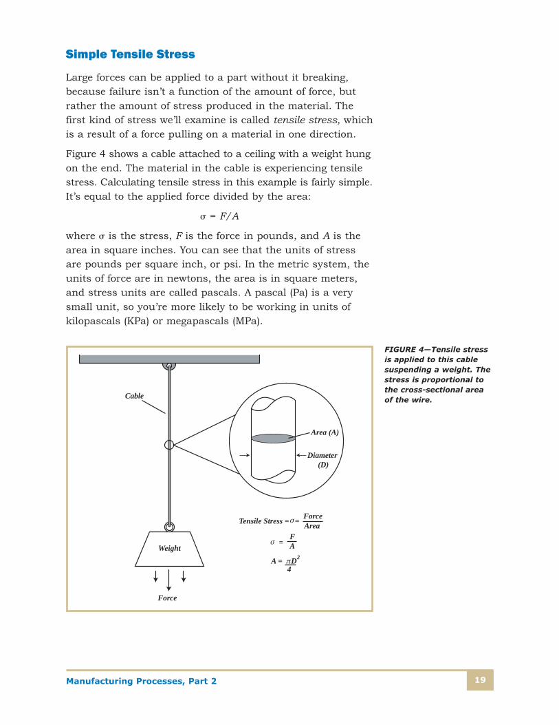
If you take a simple tension spring as shown in Figure 5,anchor one end and pull on the other, it will stretch. If you pullharder, it will stretch farther, and if you release the tension,it will go back to its original length. The distance the springwill stretch is a linear function of what’s called the springconstant (k) in a relationship called Hooke’s law:
x = F/k
where x is the distance the spring is stretched for a givenforce F, in a spring whose spring constant is k. In USCS units,F is in pounds and k is in pounds per inch. A graph of Hooke’slaw is a straight line. You know from past experience that ifyou pull too hard on the spring, it won’t return to its originallength. That’s because you’ve exceeded the elastic limit of thespring material. When a spring is stretched beyond the elas-tic limit, Hooke’s law no longer applies, and if we continuestretching, it enters a region of nonlinear deformation. Thespring has been permanently deformed when we remove thestretching force.
We’ve already said that whenever a force is applied to anymaterial or part, it will move, just as the spring stretches inthe example above. The movement resulting from an appliedstress is called strain. For the same amount of stress, partsthat are longer (longer springs) will stretch more; so the unitsof strain are inches per inch, or meters per meter. Of course,if you write this unit in a mathematical fraction, the units
Manufacturing Processes, Part 222
would cancel, which may be confusing. To avoid the difficulty,think of the amount of strain as the amount a part will stretchexpressed as a percentage of its initial length. For example, if a stress of 50,000 psi results in a lengthening of a 2-inchpart by a total of 0.0083 in., the strain would be 0.0083 � 2,or 0.00415 in./in. You can express this as a percentage bysaying the strain is 0.415 percent, or 0.00415 inches for
0
0
F
2F
L
2L
Linear Region
Length (X)
For
ce (F
)
Nonlinear Region
Spring Constant =
FIGURE 5—Hooke’s law defines how springs and other materials stretch under a load. When the forceis removed, the spring returns to its original length. If stretched too far, into the nonlinear region, thespring will have a permanent deformation. A spring constant can be calculated by measuring a changein length for a given change in force.

Manufacturing Processes, Part 2 23
every inch of part length. Under the same condition, a 3-inch part would have a total increase in length of 3 in. � 0.00415 in./in. = 0.0125 in. Machines such as thoseshown in Figure 6 can measure many material propertiesrelated to tensile stress and yield strength.
FIGURE 6—Materials are tested for tensile and yield strength in a machine that applies a known forceto a standard test specimen. Material properties such as tensile strength, yield strength, elongation,and reduction of area can be determined from a single specimen.

Manufacturing Processes, Part 224
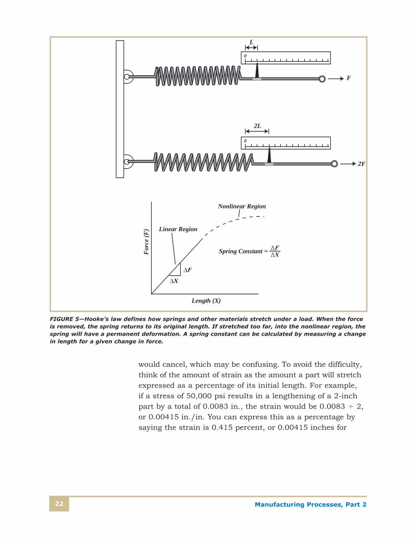
To understand what yield strength is, let’s go back to ourexample of the simple wire being pulled by a weight. If oneend is fastened to the ceiling and the other has an axial forceapplied to it, the wire is under tension, which subjects thematerial to tensile stress. In a materials laboratory, this isdone in what’s called a tensile testing machine, and the testspecimens are machined to exact sizes so that valid compar-isons between materials can be made. If we carefully applyincreasing forces and measure the resulting strain, we canfind the point beyond which the material won’t return to itsoriginal length, even after the force is removed. This point is the elastic limit, and represents the value of stress justslightly greater than the material can withstand without permanently deforming under load. Ductile metals usuallystretch considerably during the testing process, as shown inFigure 7, while brittle materials such as cast iron or whitemetal often break unexpectedly without much deformation.
FIGURE 7—Tensile test specimens are machined to exact dimensions and stretched untildestruction in a tensile test machine. The before and after dimensions of the specimen, aswell as the way in which the specimen breaks, can reveal many properties of the material.This photo shows specimens with brittle fracture (almost no elongation) and ductile frac-ture, with necking occurring before the material breaks.
Manufacturing Processes, Part 2 25
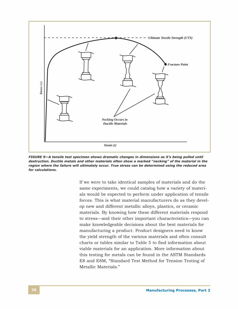
The point at which the wire breaks is called the ultimate tensile strength. The maximum stress value a material canwithstand without permanent deformation is called the yieldstrength. If we continue increasing the applied force, the wirewill continue to stretch and will eventually break. A plot ofstress versus strain can show how stiff or springy a materialis, and these plots resemble the graph in Figure 8. Figure 9shows how the shape of a test specimen changes as thestress increases over the entire loading range until it finallybreaks at the ultimate tensile point.
L o
L f
Gage Length
Gage Marks
L f L o
% ElongationL f L o
L o× 100%
Original Specimen
Total Elongation
A Standard Tensile Test Specimen
True Stress Curve
Tensile Strength
Yield Point
Elastic Limit
Proportional Limit
Strain ( )
E = = Young's Modulus
A Standard Stress-Strain Diagram for Steel
Fracture
FIGURE 8—Tensile testspecimens are preparedcarefully, and criticaldimensions are measuredafter the test is conclud-ed. A plot of the stress vs.strain over the entirerange of the test pro-duces a graph with linearand nonlinear regionsthat define how the material will performunder load.
Manufacturing Processes, Part 226
If we were to take identical samples of materials and do thesame experiments, we could catalog how a variety of materi-als would be expected to perform under application of tensileforces. This is what material manufacturers do as they devel-op new and different metallic alloys, plastics, or ceramicmaterials. By knowing how these different materials respondto stress—and their other important characteristics—you canmake knowledgeable decisions about the best materials formanufacturing a product. Product designers need to knowthe yield strength of the various materials and often consultcharts or tables similar to Table 5 to find information aboutviable materials for an application. More information aboutthis testing for metals can be found in the ASTM StandardsE8 and E8M, “Standard Test Method for Tension Testing ofMetallic Materials.”
Necking Occurs in Ductile Materials
Fracture Point
Ultimate Tensile Strength (UTS)
Strain ( )
FIGURE 9—A tensile test specimen shows dramatic changes in dimensions as it’s being pulled untildestruction. Ductile metals and other materials often show a marked “necking” of the material in theregion where the failure will ultimately occur. True stress can be determined using the reduced areafor calculations.
Manufacturing Processes, Part 2 27
A final approach to the movement of materials under stressgoes back to the idea that all materials behave as springs.Some are stiffer than others, but all materials move whensubjected to forces. In our experiments to determine the yieldstrength of a material, as we put increasing loads on a testspecimen, we get larger strains. If we were to plot on a graphthe applied stress vs. the resulting strain, we would get astraight line until we reached the elastic limit, where the linewould begin to curve. In these graphs, you’ll see the strainplotted on the X-axis, and the stress plotted on the Y-axis.The slope of the straight portion of the graph can be cal-culated by dividing Y/X, or stress/strain. Mathematically,strain is represented by the symbol , so
Slope = stress/strain = �/
Table 5
SOME YIELD STRENGTHS OF COMMON MANUFACTURING MATERIALS
MaterialYield Strength,
psi
A36 Steel, hot rolled 32–36,000
1040 Steel, hot rolled 42,000
1040 Steel, cold drawn 71,000
304 Stainless steel, hot finished, annealed 30,000
304 Stainless steel, cold worked 75,000
Aluminum 2024—T3 tempered 50,000
Aluminum 6061—T-6 temper 40,000
Copper C11000 10,000
Beryllium copper C17200, solution treated 28–55,000
Beryllium copper C17200, solution treated, aged 140–175,000
Titanium Ti-6Al-4V, solution treated, aged 160,000
Polymer, low-density polyethylene LDPE 1,300–2,100
Polymer, polyethylene terephthalate PET 8,600
Polymer, nylon 6,6 dry, as molded 8,000–12,000

Manufacturing Processes, Part 228
The units of this slope are lbs/in.2 � in./in. or psi. For manycategories of materials, this slope is relatively constant. Forexample, most steel alloys have a slope of about 29 � 106
psi. Aluminum alloys have a slope of about 10 � 106 psi.There’s some variation depending on the amount of alloyingmaterials, but it’s generally within a close range. This slope iscalled a material’s modulus of elasticity, and it’s a measure ofhow stiff or springy a material is. The modulus of elasticitydoesn’t affect the strength of the material, only its stiffness orresistance to deflection when loaded. Stiff materials such asceramics and glass, and refractory materials such as tungsten,will have a very high modulus, meaning that they’re very rigid.More elastic materials such as copper, aluminum and plas-tics will have a much lower modulus and therefore a lowervalue for the slope of the stress/strain curve. Another namegiven to the modulus of elasticity is Young’s modulus.
Other Types of Stress
Tensile stress is easy to understand because we’ve all brokenthings at one time or another by pulling on them. Other typesof stress also occur when parts are under load, and it’simportant to understand how these different stresses arise andhow materials respond. Because of their internal atomic andmolecular structure, different materials are often stronger inone direction than another, and while very high forces in onedirection won’t greatly affect a material, small forces in anotherdirection could cause it to fail. Materials whose properties are uniform in every direction are called isotropic materials,while materials that have directional differences are calledanisotropic materials. Most metals are isotropic, while manypolymers and composites are anisotropic: they have a preferredorientation for maximum strength.
Compressive Stress
Compressive stress is the opposite of tensile stress. Instead of pulling a material apart, the forces try to push it togethermore compactly. Many materials have the same yield strengthfor both tension and compression, but many don’t. Concrete,for example has a much higher compressive strength thantensile strength, and must be reinforced with steel bars,called rebar, whenever it may be in tension.

Manufacturing Processes, Part 2 29
Shear Stress
Shear stress occurs when the forces try to slice, or shear, theatoms or molecules along a plane. If you place your handsflat together in front of you and push one away and pull theother toward you, you’ll get an idea of the attempted move-ment of the planes of atoms in shear stress. Another exampleis to place your hands together around a rod (such a dowel,baseball bat, or closet rod) in front of you and push one handaway and the other toward you. If you were strong enough,you would shear the rod in half in between your hands!
Shear stress occurs on materials in tools that cut or punchparts, as illustrated in Figure 10. Tin snips cut metal sheetsby shearing action because the amount of metal available toresist the shear stress in that direction isn’t enough to over-come the applied force. Shear stress also occurs in beamsthat are fixed at the ends and loaded in the middle. Theamount of shear stress can be again calculated by a formulasimilar to the tensile stress:
= F/A ( is a Greek letter, tau)
where is the shear stress, and F and A are force and area,respectively. Notice that the formulas for tension and shearstresses differ only in the Greek letters � and . Differentsymbols are used to differentiate the types of stress—tensile(compression) or shear.
Bar
Force
Supports
Shear PlanesFIGURE 10—Shear stressoccurs where the appliedforces and reaction forcestry to cut materialsthrough a plane. Shearstresses occur in suchapplications as keywayson shafts and stampingand cutting operations.

Manufacturing Processes, Part 230
Torsional Stress
Many parts such as shafts in motors expe-rience twisting forces, which are said toproduce torsional stress. Torsion is a typeof shear stress, but if you were to analyze across section of the shaft, you would findthat at any given time, one side of the shaftwould be experiencing shear in one direc-tion while the opposite side would have it inthe opposite direction. Also, the very centerof the shaft would have no stress at all,while the outside surfaces would have thelargest amounts of shear stress. Figure 11shows a simple example of torsional shearstress produced by a twisting force—calleda couple—at the end of a shaft that’s fixedat one end. The stress at any distance rfrom the center of a cylindrical shaft can be calculated by
= M � r / J
In this expression, is the torsional shear stress in psi, Mis the moment, or torque, on the shaft, in lb-in., and J is aproperty of the shaft called the polar moment of inertia, and isa measure of its resistance to turning motions. For a uniformcylindrical shaft, J can be calculated by J = � (r) 4/2, or forhollow shafts, J = � (Ro – Ri)
4/2, where Ro and Ri are the outsideand inside radii, respectively.
Twisting forces, or torques, are very common in manufactur-ing and product operations, for example, in motors, wheels,vices, presses, axles, and levers. The stress in a shaft is verydependent on its diameters. It’s possible to make hollowshafts that are much lighter than solid ones to handle thesame torque levels, since most of the stress is generated inthe outermost parts of the shaft.
Bending Stress
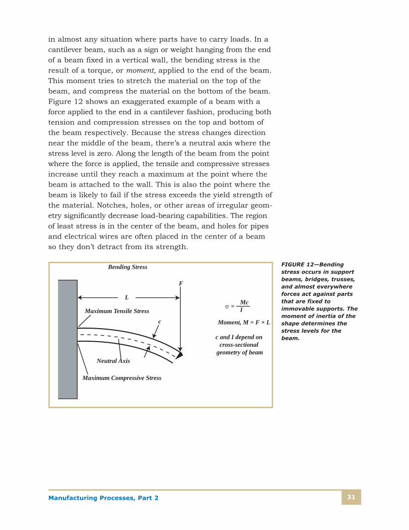
Parts such as beams that are fixed at one end and haveforces applied to the other end (or any distance away fromthe fixed end) experience bending stress. The simplest case iswhat’s called a cantilever beam, but bending stress is present
F
F
Torsional Shear Stress
FIGURE 11—Torsional shear stress occurswhen a torque tries to twist a shaft connectedto a load. It’s greatest at the surface of theshaft and decreases to zero at the center ofthe shaft. This is why lighter weight hollowshafts can often be substituted for solidshafts without sacrificing strength.
Manufacturing Processes, Part 2 31
in almost any situation where parts have to carry loads. In acantilever beam, such as a sign or weight hanging from the endof a beam fixed in a vertical wall, the bending stress is theresult of a torque, or moment, applied to the end of the beam.This moment tries to stretch the material on the top of thebeam, and compress the material on the bottom of the beam.Figure 12 shows an exaggerated example of a beam with aforce applied to the end in a cantilever fashion, producing bothtension and compression stresses on the top and bottom ofthe beam respectively. Because the stress changes directionnear the middle of the beam, there’s a neutral axis where thestress level is zero. Along the length of the beam from the pointwhere the force is applied, the tensile and compressive stressesincrease until they reach a maximum at the point where thebeam is attached to the wall. This is also the point where thebeam is likely to fail if the stress exceeds the yield strength ofthe material. Notches, holes, or other areas of irregular geom-etry significantly decrease load-bearing capabilities. The regionof least stress is in the center of the beam, and holes for pipesand electrical wires are often placed in the center of a beamso they don’t detract from its strength.
Neutral Axis
Maximum Compressive Stress
Maximum Tensile Stress
L
c
Bending Stress
McI=
Moment, M = F × L
c and I depend on cross-sectional
geometry of beam
F
FIGURE 12—Bendingstress occurs in supportbeams, bridges, trusses,and almost everywhereforces act against partsthat are fixed to immovable supports. Themoment of inertia of theshape determines thestress levels for thebeam.

Manufacturing Processes, Part 232
The amount of bending stress present also depends on theamount and shape of material available to resist the bending.The factor that affects the ability to bend a part is calledmoment of inertia, and is determined by the cross-sectionalshape of the part. In general, the more material that’s locatedaway from the neutral axis, the more difficult it will be tobend the part. This is why a yardstick is easy to bend acrossits thin dimension: there isn’t much material above andbelow the neutral axis to resist the bending moments. Veryhigh-strength beams can be constructed from relatively lightmaterials if the cross sections are oriented correctly withrespect to the applied forces. For example, houses are nowbeing built with joists or trusses made from thin sections oforiented strandboard (OSB) and two-by-fours. These beamsare much stronger and lighter than solid-wood joists used inthe past, are much more resistant to floor loads, and canspan longer distances without intermediate support.
Bending stress in a beam can be calculated by the followingmathematical relationship
� = M � c/I
where M is the moment, or torque in lb-in.; c is the distancefrom the neutral axis to the outermost fiber of the part, ininches; and I is the moment of inertia, in in.4. If you analyzethe units, you’ll see that the stress units again come out tobe pounds per square inch, or psi.
Combined Stresses
In a real application, the actual calculation of stresses can bequite complex. In very complicated configurations, they couldinclude all of the above types, plus thermal, shock, and fatiguestresses. In the past, much design work was based on designtables that were collected from data on existing products andstructures known to work in similar applications. Mathematicaltechniques using calculus could solve some simple problems,with many assumptions made to simplify problems. Today,sophisticated software programs can calculate the maximumstress levels for all different types of conditions, and can evendo nonlinear analysis where the forces have stressed thematerial into a nonlinear region of plastic deformation. Thesoftware uses a mathematical technique called finite elementanalysis (FEA), which breaks parts and assemblies into tiny

Manufacturing Processes, Part 2 33
but finite shapes called elements. Known forces and mechanicalconstraints are specified, part temperatures and gravitationalloads are listed, and materials are then assigned to the elements.The elements are mathematically “joined” and thousands ofequations are developed to describe possible motions of theconnections under the loads specified. The equations are solvedsimultaneously, stress values recorded, and then plotted(usually in color) to show areas of the parts where the high-est stresses occur. Based on these values, a designer maychoose another material, alter the shape of the existing partsto decrease stress values, or find a way to reduce loading onthe parts. Because FEA can be built into computer-assisteddesign (CAD) software, engineers or even design technicianscan easily analyze and predict the part’s performance beforeit’s manufactured.
Hardness
Hardness is a measure of a material’s resistance to localizeddeformations such as dents and scratches. Early hardnesstesting was done qualitatively on the basis of one mineral’sability to scratch another, but quantitative methods werelater devised that used a mechanical device and known loadto indent the specimen’s surface. The size and depth of theindentation were then measured and related to a hardnessnumber on a scale. A softer material will allow a deeper andlarger indentation, for example. A Swedish engineer, JohannBrinell, invented a machine to accurately test hardness, andwe use a hardness scale named after him to measure relativehardness. The Brinell hardness test uses a hardened steel or tungsten carbide ball indenter with loads from 500 to3000 kg. The Brinell hardness number (HB#) depends on theload and the size of the indentation, which is measured usinga microscope.
Hardness testing is one of the most commonly performedtests because it’s simple to do and gives accurate indicationsof other mechanical properties, such as tensile strength. Itcan quickly indicate if a material has been processed properly. Also, testing is done quickly without special testspecimens, and the hardness test equipment is relativelyinexpensive. Also, the test leaves only a small indentation

Manufacturing Processes, Part 234
and doesn’t destroy the part. Several different hardnessscales, with their characteristic penetration methods asshown in Figure 13, are used for different applications.
Today, Rockwell hardness testing is the most prevalentbecause the method requires no special skills, and is quickand accurate. Many manual machines such as that shown inFigure 14 are still used today, but automated equipment isavailable that allows quick, accurate testing with the hard-ness read directly on a meter. The measurement comparesthe indentations of a light (or minor) load of 10 kg with thatof a heavier (major) load, which can be 60, 100, or 150 kg.
D
d
Sphere
Indentation
136
Indentation
d1d1
Diamond Pyramid
Brinell
Vickers Microhardness
Knoop Microhardness
t b
lIndentationDiamond Pyramid
120
Indentation
Rockwell and Superficial Rockwell
Diamond Cone
Steel Sphere
FIGURE 13—HardnessTesting Techniques

Manufacturing Processes, Part 2 35
Different indenters are used with different loads for eachscale. The scales are labeled with letters A, B, C, D, E, F, G,H, and K; and each scale represents a different hardnessrange, although the A, B, and C scales are the ones mostcommonly used in industry. Hardened steel ball-bearingassemblies may have balls and races with hardness values ofabout RC60 (HB650), whereas softer machinable steels mayhave a hardness of RB100 (HB240).
FIGURE 14—The Rockwellhardness tester is easy touse, and can providequick and accurate knowledge of materialproperties.

Manufacturing Processes, Part 236
One of the more important aspects of hardness testing is thecorrelation between a material’s hardness and its strength.While not an exact correspondence, the harder the material,the stronger it is (and the more brittle). In Figure 15 you can see that a Brinell hardness of HB300 corresponds toapproximately 150,000 psi tensile strength, and a Rockwellhardness of RC57 corresponds to a tensile strength of about300,000 psi.
Testing hardness can quickly demonstrate whether a parthas been processed correctly for annealing, hardening, orsurface treatments such as carburizing or nitriding. Forexample, in this chart, to estimate the tensile strength of amaterial that has a hardness of HB400, read up at the 400point on the bottom axis until you get to the line marked“Tensile Strength,” then read to the right where it intersectsthe vertical axis at 200 ksi (thousand psi). To convert HB400to Rockwell C, read up to the intersection of the RC line andread to the left vertical axis, at about RC42.
110
100
90
80
70
60
50
40
30
20
10
00 100 200 300 400 500 600 700 800
300
250
200
150
100
50
0
Brinell Hardness Number (HB)
Roc
kwel
l Har
dnes
s Num
ber (
RB
or R
C)
App
roxi
mat
e Te
nsile
Str
engt
h (k
si)Tensile Strength
(RC)
(RB)
FIGURE 15—Hardnesscorrelates fairly well totensile strength.Knowing hardness, youcan estimate thestrength of the material.Different scales can beconverted if necessaryunder some conditions.

Manufacturing Processes, Part 2 37
Ductility
Ductility is a measure of how much plastic deformation amaterial can undergo without breaking. It also indicates howeasily a material can be formed, since a ductile material canbe extensively cold-worked without breaking. To measureductility, you use a standard tensile test specimen and meas-ure either its percent of elongation or its percent reduction ofarea (RA).
Percent Elongation = (lf – lo)/lo � 100
Percent RA = (Ao – Af )/Ao � 100
where lf , lo, Af , and Ao represent final and initial lengths andcross-sectional areas, respectively. Ductility can be represent-ed by the area under the stress/strain curves we discussedpreviously. Softer, ductile materials can stand extensive plastic deformation, and therefore have large areas under the curve. Very high-strength materials are often brittle; andoften fracture shortly after reaching the yield point, andtherefore have very small areas under the stress/strain curve.
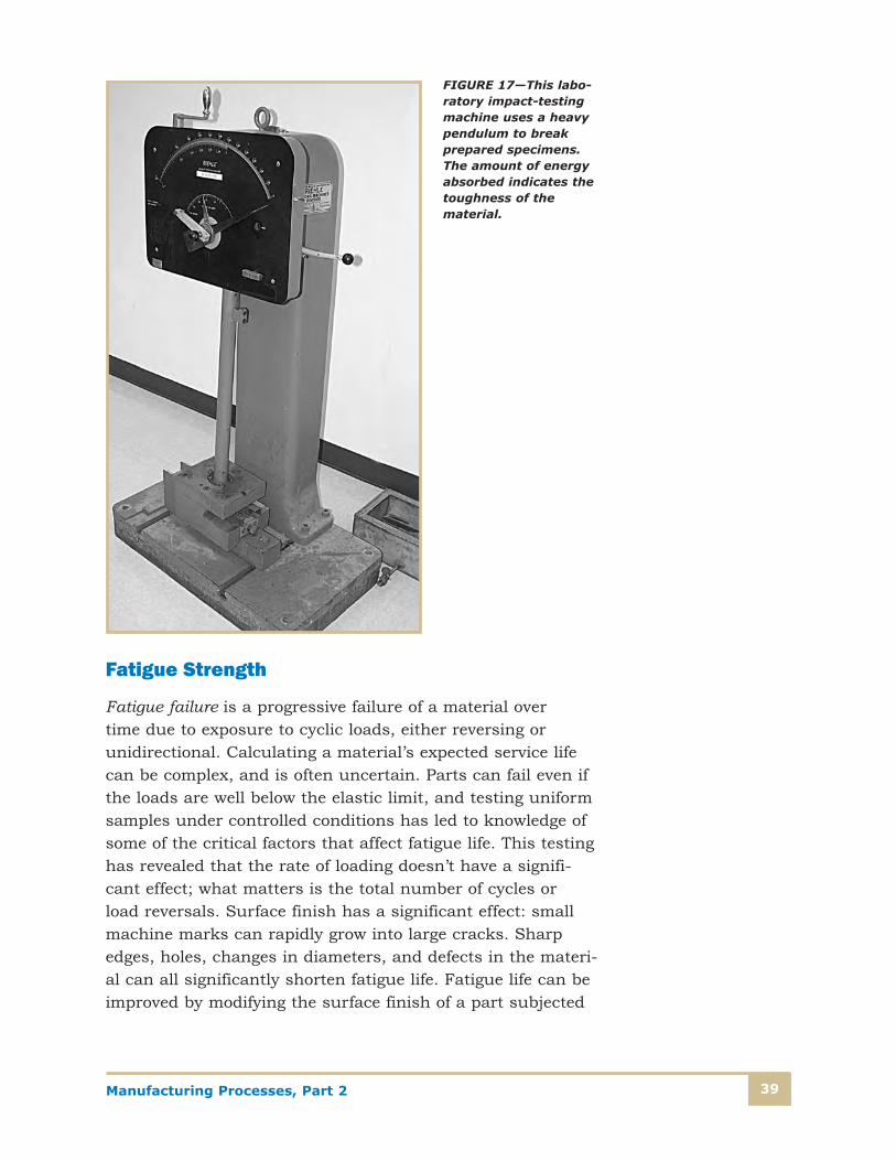
Toughness
Toughness is similar to ductility, although it’s usually used in the context of defining how much energy a material canabsorb up to the point of fracture. Many operating loads onparts and assemblies come from shock loads such as rapidstarting or stopping, impacts with objects, and even earth-quake loads. The units of toughness are energy per unit volume, and a specimen’s toughness is measured using astandardized test, either the Charpy V-notch or Izod impacttest method. A standard notched test specimen is held in aclamp, and a hammer mounted on a pendulum swings andhits it, as shown in Figure 16. The energy can be calculatedfrom the weight of the hammer and the height from which itfalls. The impact-testing machine itself can be quite large, suchas the one shown in Figure 17. The test requires a machinedspecimen that’s destructively tested, so impact testing is usuallydone only where a knowledge of the toughness of the materialis critical. Impact testing allows engineers to evaluate a material’sperformance at low temperatures (many materials become
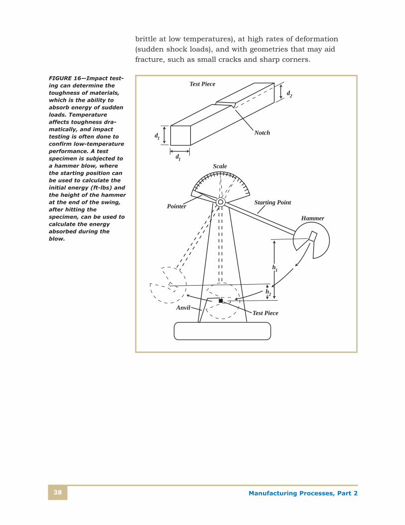
Manufacturing Processes, Part 238
brittle at low temperatures), at high rates of deformation(sudden shock loads), and with geometries that may aid fracture, such as small cracks and sharp corners.
dTest Piece
AnvilTest Piece
Pointer
Scale
Starting Point
Hammer
h
h
Notch
1
2
2
d1
d1
FIGURE 16—Impact test-ing can determine thetoughness of materials,which is the ability toabsorb energy of suddenloads. Temperatureaffects toughness dra-matically, and impacttesting is often done toconfirm low-temperatureperformance. A testspecimen is subjected toa hammer blow, wherethe starting position canbe used to calculate theinitial energy (ft-lbs) andthe height of the hammerat the end of the swing,after hitting the specimen, can be used tocalculate the energyabsorbed during theblow.
Manufacturing Processes, Part 2 39
Fatigue Strength
Fatigue failure is a progressive failure of a material over time due to exposure to cyclic loads, either reversing or unidirectional. Calculating a material’s expected service lifecan be complex, and is often uncertain. Parts can fail even ifthe loads are well below the elastic limit, and testing uniformsamples under controlled conditions has led to knowledge ofsome of the critical factors that affect fatigue life. This testinghas revealed that the rate of loading doesn’t have a signifi-cant effect; what matters is the total number of cycles or load reversals. Surface finish has a significant effect: smallmachine marks can rapidly grow into large cracks. Sharpedges, holes, changes in diameters, and defects in the materi-al can all significantly shorten fatigue life. Fatigue life can beimproved by modifying the surface finish of a part subjected
FIGURE 17—This labo-ratory impact-testingmachine uses a heavypendulum to breakprepared specimens.The amount of energyabsorbed indicates thetoughness of thematerial.
Manufacturing Processes, Part 240
to fatigue loading, and also by surface-hardening techniquessuch as case hardening. Failure by fatigue is probably thebiggest single category, accounting for as much as 90 percentof all metallic failures. Polymers and plastics are also subjectto fatigue wear, and failures there are usually sudden andwithout warning, often with catastrophic results.
Creep
Creep is a deformation of material that occurs with staticloading. Creep is often associated with parts placed in serviceat high temperatures. It’s a permanent deformation thattakes place over a relatively long period of time. Creep occursin all materials, and especially in amorphous polymers suchas plastics and rubbers. In metallic materials, it’s normallynot a problem unless the service temperature approachesabout half of the melting temperature, and the rate of creepwill increase with an increase in temperature and/or stress.A material’s creep strength is its ability to resist this type ofdeformation, but it’s not easily calculated or tested.
Material Properties Summary
We’ve discussed many important aspects of material properties,both physical and mechanical. These criteria are used toevaluate raw materials for manufacturing products and tools.Here are some key points to remember:
• Raw material costs reflect the costs to extract, isolate,process, and package the materials in a way suitable forfurther manufacturing operations.
• Material databases are available that compile relevantproperty information. Materials are categorized by typenumbers in standards maintained by various technicaland professional organizations (such as the ASTM, SAE,AISI, ASME, etc.).
• Materials of the same type number, e.g., ASTM A36, willhave the same expected level of performance regardlessof the manufacturer.

Manufacturing Processes, Part 2 41
• External forces produce stresses in materials that aredependent on the magnitude of the loads and the geometryof the parts, not on what material the part is made from.
• Failure of the part will occur if the material is unable toresist the stresses produced by the loads. Many applica-tions will consider a part to have failed if the materialexceeds the elastic limit and has been permanentlydeformed. Other applications consider fracture to be the failure point.
• Material properties change measurably with changes intemperature. For example, electrical resistance goes upand strength decreases. Materials that must perform overwide ranges of temperature should be analyzed with regardto their property changes at the temperature extremes.
• Manufacturing methods will affect material perform-ance in many applications. For example, the type of heattreatment, welding process, and machining methods allinfluence how a material performs. Other factors thatinfluence material performance are cross-sectional changes(abrupt or gradual), as well as the presence of holes, fillet,slots or corners.

Manufacturing Processes, Part 242
Self-Check 2Please fill in the correct answer.
1. Of copper and stainless steel, _______ has the greater density.
2. The two best metallic thermal conductors are _______ and _______.
3. The units of tensile strength are _______.
4. A steel rod 0.187 inches in diameter is stretched by a force of 10,000 lbs. The stress in therod is about _______.
5. When you stretch a spring until it no longer returns to its original shape, you’ve exceeded the _______.
6. The units of strain are _______.
7. Materials that have the same strength properties in all directions are called _______ materials.
8. For both tensile and shear stress, the mathematical relationship is that stress is equal to _______ divided by _______.
9. Parts that are subjected to twisting, such as drive shafts, are experiencing _______ stress.
10. The magnitude of _______ stress depends on the moment of inertia of the part and the angular relationship between the parts centerline and the direction of the load.
11. A hardness of HB300 corresponds to a tensile strength of approximately _______.
12. Material toughness at low temperatures is usually determined by _______ testing.
13. Materials sometimes fail even with stress levels well below the yield strength because they’resubjected to _______.
14. Two measures of ductility that are determined when a tensile test is done are _______ and _______.
15. Materials with higher _______ are more easily formed in manufacturing operations such asstamping or forging.
16. Materials under constant tensile loads with inadequate _______ are likely to fail over longerperiods of time, especially at higher temperatures.
Check your answers with those on page 99.

Manufacturing Processes, Part 2 43
METALLIC MATERIALS FOR MANUFACTURING
With manufactured products, materials must be consideredin two ways. First, the materials the parts are made from,and second, the tools and fixtures to make the products. Aswe said before, the goal in manufacturing is to use the mostefficient and effective materials. These materials are evaluat-ed in terms of both raw material costs and the capital andlabor costs necessary to use them in manufacturing theproduct. Trade-offs are often made in the performance of theproduct versus the cost/price of the product. As an example,wood used for gun stocks requires extensive hand finishing,but results in a unique product of great beauty. A compositeor plastic stock, on the other hand, has superior ballistic performance due to its minimal expansion from heat andmoisture, but is much less attractive. The costs to producefirearms with wooden stocks must include all of the equip-ment necessary to carve and finish the wood, while the plastic-stocked rifle requires standard machine tools andminimal finishing in production. Here’s another example.Automobiles and trucks today use many pounds of plasticsand composite materials, which were unavailable in the1940s, 1950s, and 1960s. These plastic materials replacesteel where great strength isn’t required, and increase the performance by minimizing weight and thus fuel consumption.Manufacturing costs decreased while performance increased.All of the parts shown in the front of the car in Figure 18 aremade of plastic except the hood, which is steel. This includesthe grill, the lower painted bumper (actually a cover for asteel panel), the headlight lens, and the reflective headlightholder. Similar use of plastics is made at the back of theautomobile. Manufacturing even common inexpensive productsrelies on the use of many different materials. The transformerin Figure 19 has a variety of materials used to construct areliable piece of electrical equipment.

Manufacturing Processes, Part 244
Manufacturing raw materials are divided into four generalcategories, which we’ll discuss in the following sections.Ceramics and metals have been used for thousands of years.Plastics became available in the early twentieth century, andwere developed originally as replacements for such naturallyoccurring materials as silk and rubber. Composites appearedlate in the twentieth century, but were so expensive to pro-duce that they were first used only in advanced militaryapplications such as aircraft and body armor. As manufac-turing production efficiencies improved, composites began toappear in higher-priced consumer goods.
FIGURE 18—Plastics are used in significant quantities in many new products such as automobiles.

Manufacturing Processes, Part 2 45
As you read, keep in mind the important material propertiesof each group and how these could be used in the manufac-ture of products you’re already familiar with. Revolutionaryadvances in materials can spur rapid new product development,but progress and increased efficiency are more likely to occurin small increments as we find better applications for thematerials we already know about.
Classification of Metals
This is the largest class of manufacturing materials andprobably the one you’re most familiar with. Metals them-selves are classified into ferrous and nonferrous. You’ll soonlearn of other categorizations within these areas as well.
Metals have characteristics that make them immediately recognizable: they’re solid at room temperature (except formercury); they usually have a luster, or shiny finish; they’rehard; and are good conductors of heat and electricity. Thesecharacteristics are due to the way atoms combine in metallicmaterials. The chemical properties of any material—that is,
FIGURE 19—This trans-former uses a wide variety of materials: steel, tin, copper, plastic, and polymer tape andadhesives.

Manufacturing Processes, Part 246
the way it interacts or combines with other elements—are duealmost entirely to the number of electrons in the outer shellof its atoms. In the case of metals, the outer shell containsone, two, or three electrons. Atomically, metals share theseouter electrons when they’re arranged in a crystal structure,and the effect is that the electrons are free to move amongthe atoms without being specifically tied to any one location.A good way to think of metallic bonds is to picture the posi-tive ions of the nuclei surrounded by a “sea” of electrons, asshown previously in Figure 2. Because the electrons canmove relatively freely, metals are able to conduct both heatand electricity, and metallic bonds can be deformed withoutbreaking the structure. This is why many metals are ductileand able to be formed and hammered without shattering.
Metallic atoms combine with each other in very definite pat-terns where the atoms are lined up in regular shapes such as cubes or boxes. There are over a dozen different types ofcrystal structures—sometimes called lattices—but metals aremostly found in three of them:
• Body-centered cubic
• Face-centered cubic
• Hexagonal close-packed
These lattice structures weren’t known or understood untilafter the invention of x-ray diffraction in the first half of thetwentieth century.
Figure 20 shows how the atoms are arranged in unit cells for some of the cubic types, which are the principal arrange-ment for iron and steel alloys. The type of lattice structure isaffected by the size and type of the atoms. Why are latticestructures important in the study of metals? The crystalstructure, the types of bonds between atoms, and the impurities within the structure determine such mechanicalproperties as strength and toughness, as well as the failuremechanism of the material under stress. When a piece of steelor copper yields—begins to deform—under an outside force,it’s the crystal lattice bonds that are being broken. In mostcases, the failure occurs along a plane within the crystal: onelayer of atoms slides along another layer. Anything that affects

Manufacturing Processes, Part 2 47
this ability of layers of atoms to slide past each other will affectthe strength and properties of the material. Other materialsalso have atoms arranged in crystal structures, and many ofthe properties of metals will also apply to these similarlyformed materials.
Arrangement of Atoms in a Unit Cell
Simple Cubic Structure
Body-Centered Cubic Unit Cell
Face-Centered Cubic Structure
FIGURE 20—Metals mostlyexist in very orderedcrystal lattice structureswith regular spacingbetween atoms.Impurities mix within thisstructure, sometimescausing disruptions withboth good and badeffects. Many metalschange their structurewith temperaturechanges; this is called aphase change.

Manufacturing Processes, Part 248
The most common metals in a manufacturing environment are
• Iron and steel, and steel alloys—used primarily for theirstrength and ease of manufacturing
• Aluminum and aluminum alloys—used because of their high strength-to-weight ratio and natural corrosion resistance
• Copper and copper alloys—used because of their electricaland thermal conductivity, ductility, and corrosion resistance
• Nickel and chromium—used as alloying materials for steel,as well for resistance to corrosion
• Refractory metals—such as tungsten and molybdenum,used both as alloying materials to strengthen other metalsand also, in their pure form, for their ability to withstandvery high temperatures
Alloying
More than a hundred different elements exist, each with different characteristics, but very few materials are used intheir pure form. As we mentioned before, adding two or moreelements produces alloys, and the materials are chosen toachieve specific properties in the final alloy. When two mate-rials are mixed, one can be dissolved in the other, in the waysugar or salt dissolves in water. Or the crystal structurechanges to a new form where the atoms take on differentpositions relative to one another. Even though the material issolid, we still say that a phase change has occurred when dif-ferent crystal structures are formed. However, phase changesusually occur because of temperature changes.
Ferrous and nonferrous materials are both very important formanufacturing purposes. Ferrous materials all use iron as amajor constituent, but while iron has some important uses,it’s seldom used without some alloying ingredients to make itstronger, more ductile, or more corrosion resistant. Steel, analloy of carbon and iron, is probably the most importantmetal in use today, and we’ll discuss its properties in detail.

Manufacturing Processes, Part 2 49
Knowledge of the metallurgy of steel will help you understandhow other materials are processed and used, and also willhelp you know when steel is a better or inferior material fordifferent applications.
Nonferrous materials, particularly aluminum and copper, arealso used extensively in manufacturing. Aluminum is one ofthe most common elements on earth, but it’s not found in apure state. Because of the difficulty of extracting aluminumfrom the ore, it wasn’t used commercially to any extent untilwell into the nineteenth century. Copper is found in a purestate and has been used for manufacturing for many centuries.Alloying copper with zinc and tin yields brass and bronze,respectively. Modern breech-loading firearms exist thanks tothe development of an alloy know as “cartridge brass,” whichwas ductile enough to be able to seal the combustion cham-ber, yet strong enough to avoid fracture when the case wasextracted from the chamber.
As you learned in the previous units, standards for materialsare maintained by voluntary industry associations. Differentindustries were once primarily responsible for the develop-ment of the different alloys, and numbering them becamesomewhat confusing. ASTM has sought to bring order to theoverlapping systems by the adoption of a Unified NumberingSystem (UNS) as defined by their standard, E 527-83 (1991),Standard Practice for Numbering Metals and Alloys (UNS). TheUNS coordinates the alloy designations of the AluminumAssociation (AA), the American Iron and Steel Institute (AISI),the Copper Development Association (CDA), and the Societyof Automotive Engineers (SAE). At one time, each of theseorganizations had its own specifications, and the UNS systemhas retained many of the numbers from the old standards(for instance, the UNS system utilizes the same classificationnumber as the AISI, just not the AISI prefix). Table 6 showsthe UNS numbering system for various metals and alloys, aswell as the organization responsible for the standards. For ironand steel specifications, the 4-digit AISI numbers shown inTable 7 are still in common use, especially for machine tool andmanufacturing applications, and the SAE and ASTM standardsuse the same numbers. Note that the UNS designationsincorporate the 4-digit AISI numbers.

Manufacturing Processes, Part 250
Table 6
UNIFIED NUMBERING SYSTEM (UNS) MATERIAL IDENTIFICATION
UNS Series MaterialResponsible
Organization
A00001 to A99999 Aluminum and aluminum alloys AA
C00001 to C99999 Copper and copper alloys CDA
D00001 to D99999 Specified mechanical property steels SAE
E00001 to E99999 Rare earth and rare-earth-like metals and alloys ASTM
F00001 to F99999 Cast irons ASTM
G00001 to G99999 AISI and SAE carbon and alloy steels (except tool steels) AISI
H00001 to H99999 AISI and SAE H-steels AISI
J00001 to J99999 Cast steels (except tool steels) ASTM
K00001 to K99999 Miscellaneous steels and ferrous alloys ASTM
L00001 to L99999 Low-melting metals and alloys ASTM
M00001 to M99999 Miscellaneous nonferrous metals and alloys ASTM
N00001 to N99999 Nickel and nickel alloys SAE
P00001 to P99999 Precious metals and alloys ASTM
R00001 to R99999 Reactive and refractory metals and alloys SAE
S00001 to S99999 Heat- and corrosion-resistant (stainless) steels ASTM
T00001 to T99999 Tool steels, wrought and cast AISI
W00001 to W99999 Welding filler metals
Z00001 to Z99999 Zinc and zinc alloys ASTM
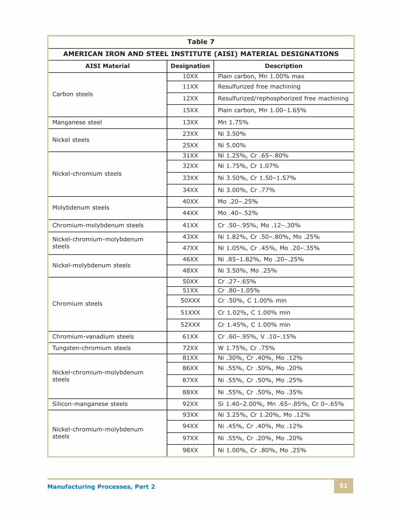
Manufacturing Processes, Part 2 51
Table 7
AMERICAN IRON AND STEEL INSTITUTE (AISI) MATERIAL DESIGNATIONS
AISI Material Designation Description
Carbon steels
10XX Plain carbon, Mn 1.00% max
11XX Resulfurized free machining
12XX Resulfurized/rephosphorized free machining
15XX Plain carbon, Mn 1.00–1.65%
Manganese steel 13XX Mn 1.75%
Nickel steels23XX Ni 3.50%
25XX Ni 5.00%
Nickel-chromium steels
31XX Ni 1.25%, Cr .65–.80%
32XX Ni 1.75%, Cr 1.07%
33XX Ni 3.50%, Cr 1.50–1.57%
34XX Ni 3.00%, Cr .77%
Molybdenum steels40XX Mo .20–.25%
44XX Mo .40–.52%
Chromium-molybdenum steels 41XX Cr .50–.95%, Mo .12–.30%
Nickel-chromium-molybdenumsteels
43XX Ni 1.82%, Cr .50–.80%, Mo .25%
47XX Ni 1.05%, Cr .45%, Mo .20–.35%
Nickel-molybdenum steels46XX Ni .85–1.82%, Mo .20–.25%
48XX Ni 3.50%, Mo .25%
Chromium steels
50XX Cr .27–.65%
51XX Cr .80–1.05%
50XXX Cr .50%, C 1.00% min
51XXX Cr 1.02%, C 1.00% min
52XXX Cr 1.45%, C 1.00% min
Chromium-vanadium steels 61XX Cr .60–.95%, V .10–.15%
Tungsten-chromium steels 72XX W 1.75%, Cr .75%
Nickel-chromium-molybdenumsteels
81XX Ni .30%, Cr .40%, Mo .12%
86XX Ni .55%, Cr .50%, Mo .20%
87XX Ni .55%, Cr .50%, Mo .25%
88XX Ni .55%, Cr .50%, Mo .35%
Silicon-manganese steels 92XX Si 1.40–2.00%, Mn .65–.85%, Cr 0–.65%
Nickel-chromium-molybdenumsteels
93XX Ni 3.25%, Cr 1.20%, Mo .12%
94XX Ni .45%, Cr .40%, Mo .12%
97XX Ni .55%, Cr .20%, Mo .20%
98XX Ni 1.00%, Cr .80%, Mo .25%

Manufacturing Processes, Part 252
Solidification of Metals and Grain Structure
All the heavy metals—those with atomic weights larger thanthat of beryllium—were produced by nuclear reactions withinexploding stars billions of years ago, and were therefore oncevery hot. All of the materials now on Earth were also veryhot, slowly collecting as the planet formed, and passing froma hot gas to a liquid and finally to a solid. Many importantproperties of metals can be understood by learning how theatoms collect together as they solidify and what this does totheir mechanical properties after the metal has cooled. Asmentioned previously, atoms collect in regular crystal latticestructures whose shapes are determined by the size of theatoms. Impurities within the lattice often assume a positionwithin the spaces between the atoms of the bulk material.
Figure 21 show a sequence of the formation of a metalliccrystal lattice as it changes from a liquid to a solid. At differ-ent locations within the liquid metal, some of the atomsclump together at a nucleation point where the internal energy is lower, sometimes around an impurity atom. Otheratoms start to build the lattice by attaching to the ends ofthose atoms, and gradually a solid crystal begins to form. If there were one nucleation point, and if the crystal weregrown under very controlled conditions, a single solid crystalof metal could be grown; however, under normal conditionsthere are many nucleation points in the liquid and thereforemany individual crystal are grown. (Note: The figure showsonly a two-dimensional view, but growth occurs in all threedimensions.) As the individual crystals grow, their randomorientation eventually causes them to run into one another,forming irregular boundaries. The boundaries are regions ofdisordered atoms, often containing impurities that were solid-ified last. Each of the individual crystals is called a grain, andthe contact region with other crystals is called the grainboundary. The metal is weaker at the boundaries because thebond between the atoms from one grain to another is weaker.Grain boundaries are often the areas where cracks or defectsoriginate or propagate in a metal under stress.

Manufacturing Processes, Part 2 53
The size of the grains in a metal has a very significant effecton its mechanical properties. Large grains indicate lowerstrength and higher ductility, whereas smaller grains usuallymean higher strength. Large grains allow cracks that startfrom stresses to travel farther into the metal, possibilityresulting in failure. Small grains don’t allow cracks to propagate readily because of the many changes in directionrequired for a crack to pass around small grains. One of thereasons for adding particular alloying elements is that theytend to keep grain sizes smaller during solidification by providing for more nucleation points, and by disrupting large-grain growth due the presence of odd-sized atoms that distortthe crystal as it attempts to form. An example is the additionof beryllium to copper to make beryllium-copper, which issignificantly stronger and harder than pure copper.
Nucleation Crystal Growth
Grain Formation Grain Boundaries
Solidification and Grain Growth in Metals FIGURE 21—As a metalcools, atoms in differentlocations begin to solidifyat nucleation sites wherecrystals start to grow. Asthey begin to run intoeach other, irregulargrain boundaries form,which are eventually visible in a microscopeand sometimes with thenaked eye. Impurities inthe metal are oftentrapped at the bound-aries, weakening it.

Manufacturing Processes, Part 254
Cold-working a metal part by manufacturing operations suchas stamping, rolling (shown in Figure 22), drawing, or forgingwill break larger and softer grains into smaller grains, makingthe material harder. In general, any process that makes thegrains smaller will tend to make the material stronger, harder,and less ductile. Often, a heat treatment called annealing isnecessary between operations to make the material soft againso that additional work can proceed. Annealing involves rais-ing the temperature of the part and soaking—the prolongedheating of a metal at a selected temperature—it for longenough to allow the atoms to reform into larger grains.
Steel
As we mentioned before, steel is probably the most importantmanufacturing material, because of its high strength and relatively easy processing. Even with the great amount ofplastic materials being used today, steel often forms the high-strength backbone for many products. Steel is an alloy ofcarbon, iron, manganese, and other alloying elements addedfor specific purposes. Carbon has the most dramatic effect onthe properties of various steels, with more carbon generallymaking the steel stronger, harder, and less ductile. Highercarbon contents require more precise and more complex heattreatments to maintain high strength and toughness. Improperheat treatment during or after manufacture of the materialwill result in brittleness. Steel and other specialty iron alloyscan be classified according to the amount of carbon andother alloying agents, as shown in Figure 23.
Elongated and Flattened Grains
Large Grains
Feed
RollersFIGURE 22—In cold-working operations suchas rolling, materials withlarge grains are rolledinto plates with smaller,elongated grains. Thedistorted grains makethe material harder andstronger. If further man-ufacturing operations aredesired, the material issoftened by an annealingprocess that restoresductility and lowershardness and strength.

Manufacturing Processes, Part 2 55
The Metallurgy of Steel
As you’re aware, steel is an alloy of iron, carbon, and otherelements such as manganese and silicon, depending on whatproperties are desired for the manufactured part. To under-stand how the composition and processing affect the finalproperties of steel, you must understand a little about what’scalled the iron-carbon phase diagram. All materials exist asone of three phases, solid, liquid, or gas, or mixtures ofthese. When a material is a solid, we say it’s in a solid phase.The phase a material is in depends on its temperature, andas the temperature is increased (increasing internal heatenergy), a material will change from solid to liquid (at themelting point), and then from a liquid to a gas (at the boilingpoint). Pure materials, such as pure iron or pure aluminum,will have distinct melting and boiling points, but if the materialcontains any impurities, the temperature at which meltingand boiling occur will be changed. In fact, in an alloy such as steel, the mixture of carbon and iron won’t have a single
Metal Alloys
Ferrous
Nonferrous
Steels
CastIrons
Malleable
White
Ductile
Gray
High Alloy
Low Alloy
Stainless
Tool
PlainHeat
Treatable
Plain
Plain
High StrengthLowCarbon
Medium Carbon
High Carbon
FIGURE 23—Ferrous materials can be divided into smaller subgroups depending on their carbon andother alloy content.

Manufacturing Processes, Part 256
distinct melting point as the temperature is raised, but ratherit will gradually change from a solid to a liquid over a broadtemperature range, and will consist of a mush, a mixture ofsolid and liquid, until it all turns to liquid.
Another important fact about temperature changes is thatmaterials will often undergo a change in their crystal structure,a phase change, as the temperature is increased or decreased.The iron-carbon phase diagram plots these changes of structurewith a graph that has the percent of carbon as the X-axis,starting at 0 percent carbon, or pure iron, on the extreme left.Increases in the percent of carbon are shown in increasingincrements to the right of the pure-iron point. At each percentcarbon value, metallurgists have plotted the temperature atwhich crystal structure phase changes occur. This results ina phase diagram with smooth lines that show the temperatureat which phase changes occur as a function of the percent ofcarbon. Figure 24 shows a simplified iron-carbon phase dia-gram that you can refer to as you read and consider some ofthe concepts in this section. The portions labeled “austenite,”“pearlite,” “cementite,” and so forth, are different crystalstructures of steel that exist at different temperatures anddifferent concentrations of carbon.
When we look at an iron-carbon phase diagram, we’re mostlylooking at the solid phase of the various allotropes of ironand carbon. An allotrope is a mixture that has the samechemical formula but different forms of crystal structure.There are several allotropes of iron that are important tounderstand. Ferrite, also known as �-iron (“alpha” iron), is a crystal structure that’s called body-centered cubic, whichmeans that in a unit of crystal structure, there’s an atom ateach corner of a cube surrounding an atom in the middle.Larger crystals are built up from stacks of these unit crystals,and the corner atoms will be corners for more than one unitcrystal. Ferrite is relatively low strength and ductile, makingit easy to form and machine. Ferrite can dissolve only a verysmall amount of carbon, a maximum of 0.021 percent at 910ºC.Above 910ºC in pure iron, this ferrite crystal structure changesto austenite, or �-iron (“gamma” iron), which is a face-centeredcubic structure. In this form, there’s an atom on each face ofthe cube, surrounding an atom in the middle. Austenite isn’tgenerally stable below 910ºC in pure iron, but the important
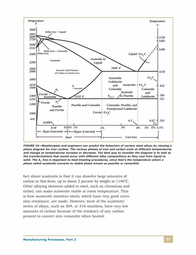
Manufacturing Processes, Part 2 57
fact about austenite is that it can dissolve large amounts ofcarbon in this form, up to about 2 percent by weight at 1146ºC.Other alloying elements added to steel, such as chromium andnickel, can make austenite stable at room temperature. Thisis how austenitic stainless steels, which have very good corro-sion resistance, are made. However, most of the austeniticseries of alloys, such as 304, or 316 stainless, have very lowamounts of carbon because of the tendency of any carbonpresent to convert into cementite when heated.
3000280228002720
26002552
2400
2200
20662000
1800
16701600
140013331200
1000
410
Austenite inLiquid
2066 F
Austenite
ACementite
1333 F
AustentiteLedeburite
andCementite
Austeniteto Pearlite
Cementiteand
Ledeburite
Austentite + Fe3 C
Fe3C
A3
Austenite Solid Solutionof Carbon in Gamma Iron
A1
Ferrite + Austentite
Pearliteand Ferrite
Pearlite and Cementite Cementite, Pearlite, andTransformed Ledeburite
Fe3CFerrite +
0.50 0.83% 1% 3%2% 4% 5% 6%
6.67
6.5%
Steel
Hyper-EutectoidHypo-Eutectoid
Cast iron
4.3-0.008%
A1,2,3
Fe3 CLiquid +
15391492
1400
1130
910
760723
210
TemperatureF
Delta Iron + Liquid
Delta Iron + AusteniteDelta Iron
Ferrite
TemperatureC
FIGURE 24—Metallurgists and engineers can predict the behaviors of various steel alloys by viewing aphase diagram for iron–carbon. The various phases of iron and carbon exist at different temperaturesand change as temperatures increase or decrease. The best way to consider the diagram is to look atthe transformations that would occur with different alloy compositions as they cool from liquid tosolid. The A1 line is important to heat-treating procedures, since that’s the temperature where aphase called austenite converts to stable phase known as pearlite or cementite.

Manufacturing Processes, Part 258
So what happens if we take a molten mixture of say, 0.5 per-cent carbon and iron, and gradually cool it from a liquid tosolid and finally down to room temperature? The phase dia-gram tells us some of the important changes that occur tothis particular alloy of steel. After it cools below the meltingpoint (about 1525ºC), the solid crystal structure that devel-ops is austenite. It remains as austenite as the steel cools,until it reaches about 750ºC. At that point it crosses theupper critical line and changes to a mixture of ferrite andaustenite. As the temperature decreases, the amount of carbon is too great to remain dissolved in the decreasingamounts of austenite, and it begins to form iron carbide(Fe3C), which is a stable compound of iron and carbon. Ironcarbide is a compound of iron, with very strong bondsbetween the carbon and iron atoms, and it’s not an alloy.Iron carbide is extremely strong, but also extremely hard andbrittle. It’s often used as tool points for machine tools thatremove metal, such as lathes and milling machines.
Iron carbide is also known as cementite, and contains about6.68 percent carbon. As the carbon is driven out of solutionas the steel cools—called precipitation—more and morecementite is formed, in layers alternating between the cementite and ferrite. This layering formation of cementiteand ferrite is known as pearlite, because under a microscopeit looks like pearls. Finally, at the lower critical temperatureof 723ºC, all of the possible cementite has formed, and thesteel now consists of a mixture of ferrite and pearlite. Pearliteis much stronger and tougher than ferrite, although it’s stillfairly easy to work.
What do you think happens if we start with an alloy that hasa greater percent carbon? At the special condition of about0.8 percent carbon, the upper and lower critical temperaturecoincide and all the carbon dissolved in the austenite above723ºC will precipitate out into pearlite. All of the steel at thisspecial mixture, called the eutectoid alloy, will consist of 100percent pearlite, while carbon contents less than the eutec-toid composition will cause mixtures of ferrite and pearlite,the amount of pearlite increasing with the carbon content.

Manufacturing Processes, Part 2 59
Above the eutectoid composition of 0.8 percent carbon, theupper critical temperature begins to rise with increasing car-bon content. This means that even the austenite isn’t able todissolve all of the carbon present below this temperature, andwhen the alloy is cooled below the upper critical temperature,the excess carbon forms cementite again. At temperaturesbelow the upper critical temperature and above the lowercritical temperature, the steel consists of a mixture of austen-ite and cementite. When the steel is further cooled below723ºC—the lower critical temperature—the carbon that hasn’t formed cementite changes into pearlite, so that steelsabove the eutectoid composition will consist of pearlite andcementite. As the carbon content increases further, more andmore cementite will appear. The iron-carbide phase diagramsusually only goes up to about 4–5 percent carbon becauseabove this amount, the material is considered to be cast iron.
Another important crystal structure of steel is martensite. Allof the transformation we’ve talked about so far assume that thetemperature decreases slowly enough to allow the iron andcarbon atoms to move around as they realign themselves intonew crystal formations. Martensite is formed when austeniteis cooled rapidly (quenched) by either cool air, water, or oil.When high-carbon-content steel is heated above the uppercritical temperature to form austenite and then cooled rapidly,the carbon becomes trapped in a body-centered tetragonalcrystal structure. This structure is highly stressed due to the stretching of the crystal by the carbon atoms, and as aresult, martensite is extremely hard, strong, and brittle. Inorder for martensite to be useful for tools and manufacturedproducts, the quenched steel containing martensite can betempered, that is, reheated to a temperature below 723ºC fora period of time, and slow cooled. Tempering will restore someof the ductility without losing a great deal of the strength.Sometimes alloys such as nickel and chromium are added to give some corrosion resistance and to stabilize the crystalstructure. These possible transformations of austenite, asshown in Figure 25, form the basis of our ability to producealloys with properties tailored to specific manufacturing needs.
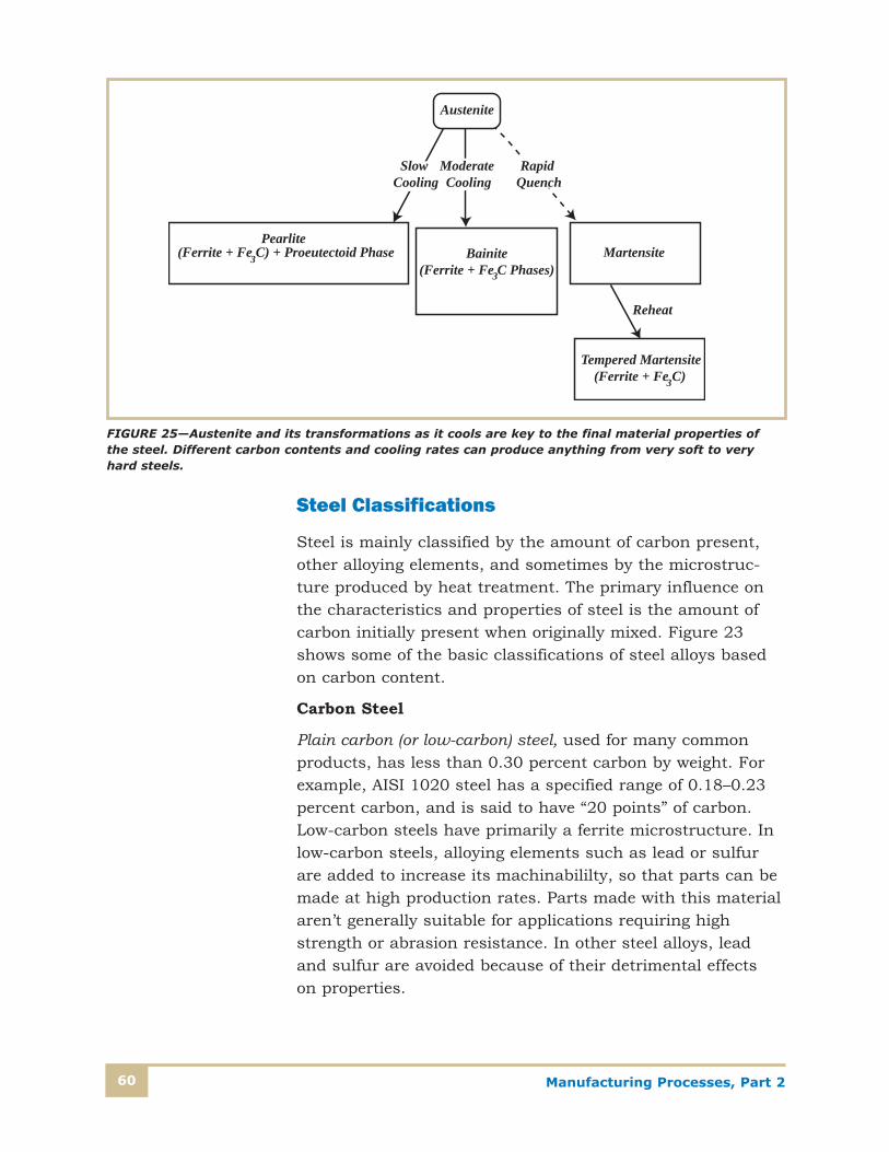
Manufacturing Processes, Part 260
Steel Classifications
Steel is mainly classified by the amount of carbon present,other alloying elements, and sometimes by the microstruc-ture produced by heat treatment. The primary influence onthe characteristics and properties of steel is the amount ofcarbon initially present when originally mixed. Figure 23shows some of the basic classifications of steel alloys basedon carbon content.
Carbon Steel
Plain carbon (or low-carbon) steel, used for many commonproducts, has less than 0.30 percent carbon by weight. Forexample, AISI 1020 steel has a specified range of 0.18–0.23percent carbon, and is said to have “20 points” of carbon.Low-carbon steels have primarily a ferrite microstructure. Inlow-carbon steels, alloying elements such as lead or sulfurare added to increase its machinabililty, so that parts can bemade at high production rates. Parts made with this materialaren’t generally suitable for applications requiring highstrength or abrasion resistance. In other steel alloys, leadand sulfur are avoided because of their detrimental effects on properties.
Slow Cooling
Moderate Cooling
Rapid Quench
(Ferrite + Fe C) + Proeutectoid Phase3 Bainite(Ferrite + Fe C Phases)3
Martensite
Tempered Martensite(Ferrite + Fe C) 3
Pearlite
Reheat
Austenite
FIGURE 25—Austenite and its transformations as it cools are key to the final material properties ofthe steel. Different carbon contents and cooling rates can produce anything from very soft to veryhard steels.

Manufacturing Processes, Part 2 61
Medium-carbon steels contain between 0.30 and 0.50 per-cent carbon and are used for parts requiring good strength,toughness, ductility, and abrasion resistance. Medium-carbonsteels tend to have mixtures of ferrite and pearlite, and thushigher strength. High-carbon steels have 0.50–1.0 percentcarbon, and are used where high strength and hardness arerequired. They have mixtures of pearlite and cementite, whichmakes them harder and more brittle as well as much stronger.They’re used for cutting tools, knives, high-strength gears,and other parts subjected to great stresses. Steel shafts andbearings are made from high-carbon steel because of its highstrength and abrasion resistance. With special surface heattreatments, it’s possible in some applications to use a low-carbon steel because of its machinability and ductility, but addhigher percentages of carbon to the outer layers of the material(often less than 0.010 inches) to produce a hard outer shellthat is resistant to wear. This process is called carburizing.
High-Strength, Low-Alloy Steel
A recent development in steel manufacturing is the productionof high-strength, low-alloy (HSLA) steels. The steels in thisgroup contain less than about 10 percent of the total alloyingelements such as copper, vanadium, nickel, and molybdenum,and therefore are somewhat less expensive to manufacture.However, they have high strength—in excess of 70,000 psi—and can be machined and formed. Because of their strength,less material can be used in critical applications such as bridgebeams, towers, columns, and other building structures, whichsaves space and lowers material costs. They also offer morecorrosion resistance than plain carbon steels.
Alloy Steel
In addition to manganese, other alloying elements and groupsof elements that are added to steel to enhance its propertiesfor specific applications include nickel, chrome, molybdenum,vanadium, copper, and silicon. Nickel is added to improvehardenability, toughness, and also corrosion resistance, espe-cially when it’s combined with chromium to make the groupof what are called stainless steels.
Manufacturing Processes, Part 262
Stainless Steel
Stainless steels are so called because of their resistance tocorrosion from environmental factors or chemicals. The mainalloying ingredient that gives this resistance is chromium (atleast 11 percent), but nickel and molybdenum are oftenadded to enhance the stainless characteristics. Stainlesssteels are classified into three main groups depending on the amount of carbon and other alloying elements: ferritic,austenitic, and martensitic.
Ferritic stainless steel
These steels contain lower amounts of carbon and has a fer-rite microstructure. They have from 11 percent to over 25percent chromium, and are used for applications such asautomotive exhaust components, chemical tanks, high-temperature valves, glass molds, and combustion chambers.Examples of ferritic stainless steels would be AISI 409 (UNSS40900) and AISI 446 (UNS S44600).
• Austenitic stainless steel contains less than 0.10 percentcarbon, 17 to 19 percent chromium and 8 to 15 percentof nickel. The extra chromium and nickel allow theaustenite phase to be stable at room temperatures.Stainless alloys such as AISI 304 and 316L (UNS S30400and S31603) have exceptional corrosion resistance, andthey’re used on applications such as chemical processingequipment, food preparation equipment, dairy equipment,and exterior decorative items such as tableware and grillwork. Austenitic stainless steels are nonmagnetic, a useful property for some applications.
• Martensitic stainless steel contains higher ranges of carbon (typically 0.15–0.70 percent) and is produced byquenching and tempering to desired properties. Martensiticis very hard and strong, and is used for applications thattake advantage of these characteristics, such as knives andcutlery, manufacturing cutting tools, rifle barrels, surgicaltools, and ball bearings. These steels are magnetic, anddon’t have as much corrosion resistance as the ferritic oraustenitic stainless types, although somewhat more thanthe plain carbon steels.
Manufacturing Processes, Part 2 63
Heat Treatment of Steel
The principal purpose of heat treatment is to control theamount and distribution of ferrite, cementite, pearlite, andaustenite in a steel alloy, which in turn is responsible for itsphysical properties. There are many heat treatment procedures,and many must be carried out after operations such as weld-ing to ensure that the final product doesn’t have any residualstresses that may later result in cracking or failure. Heattreatment is often quite complex and requires sophisticatedinstrumentation to achieve a consistent high-quality product.
Heat treatment may be done for any the following reasons:
• To soften the material to improve its ability to be workedby further manufacturing operations such as stamping,rolling, forging, or machining
• To relieve residual stresses in the material that resultfrom manufacturing operations
• To ensure dimensional stability after manufacture
• To increase the strength and hardness of the material
• To increase toughness and decrease brittleness
Understanding some important features of the iron-carbidephase diagrams is important to understanding how differentsteel alloys will respond to treatment at different temperatures.However, the same principles discussed here will apply tononferrous metals as well. The iron-carbon phase diagramshown in Figure 26, which is similar to the one we discussedpreviously, helps us understand some of the heat treatmentprocesses industry uses to manufacture steel products.Typical samples of heat-treatment procedures are shown inFigure 27. The time-versus-temperature diagrams will varyfor different parts and alloys.

Manufacturing Processes, Part 264
900
800
700
1700
1600
1500
1400
1300
1200
Normalizing Acm
Full Annealing
A3
A1 Spheroidizing
0 0.2 0.4 0.6 0.8 1.0 1.2 1.4 1.6
Tem
pera
ture
( C
)
Tem
pera
ture
( F
)
Composition (% Carbon by Weight)
FIGURE 26—The temper-ature of the various heattreatment processes thatare used for steeldepends on the carboncontent. Line A1 is knownas the lower critical temperature, and A3and Acm are the uppercritical temperatures for hypo- and hyper-eutectoid steel alloys.Hypo-eutectoid refers tosteels with less thanabout 0.8 percent carbon, while hyper-eutectoid alloys havemore than 0.8 percentcarbon.
Very Slow Cooling in Furnace
Slow Cooling
Upper Critical Temperature
Full Annealing
Lower Critical Temperature
Room Temperature
Slow Cooling
Lower Critical Temperature
Upper Critical Temperature
Stress-Relief Annealing
Tem
p
Tem
p
Slow Cooling
Tempering Temperature
Quenching
Tem
p
Upper Critical Temperature
Quenching and TemperingThrough-Hardening
Slow Cooling
NormalizingRoom
Temperature
Room Temperature
Room Temperature
Tem
p
Upper Critical Temperature
Lower Critical Temperature
Time Time
TimeTime
FIGURE 27—These diagrams represent typical time-versus-temperature diagrams that might be usedfor the various heat treatments of steel alloys.

Manufacturing Processes, Part 2 65
Quenching is a process of rapidly cooling steel from a highertemperature, typically producing martensite or other desirablemicrostructures. The quenching can be done in air, water, oroil, and the rate of change of temperature often must be con-trolled precisely to determine the final composition. A sourceof typical heat treatment procedures and the theory behindthem is available in publications such as The Metals Handbook,by the American Society of Metals (ASM).
When materials are manufactured using processes such asrolling, stamping, forging, or drawing, the grain structure of ametal changes from large grains in unprocessed steel to smaller,sometimes deformed structures. Normalizing is a process thatrestores grain structure to a near-original condition so thatfurther processing, called refining the grain structure, canoccur. Normalizing is done by heating the metal above theupper critical temperature to transform to austenite. Thelonger the material is held at this temperature, the larger thegrains will grow. After soaking the desired time, the materialis allowed to slow cool in air.
Annealing is a process of slowly raising the temperature of ametal to a specific value, soaking for a period of time, andthen slow cooling back to room temperature. The effect is tosoften the material and make it more ductile and less brittle,and to relieve any residual stresses that may be present dueto forming operations. Time is an important factor for eachpart of the procedure, and annealing processes are often controlled by computers. The metal grain structures becomebroken and smaller by cold-working processes such as forming,rolling, or stamping, and material is often annealed so thatfurther operations can continue without the material cracking.
Spheroidizing is a process that allows harder steels, with larg-er concentrations of coarse pearlite, to be softened for furtheroperations such as machining or forging. The process involvesheating the steel to just below the lower critical temperatureand holding at that temperature for 15 to 25 hours. During thissoak, the cementite particles tend to combine into sphericalparticles, hence the name spheroidizing.
Manufacturing Processes, Part 266
Aluminum
Aluminum is one of the most common metallic elements in theEarth’s crust, but is always found combined with oxygen invery stable compounds such as silicon dioxide (SiO2), which issand. This makes it very hard to extract and process. Today,most aluminum is extracted from bauxite ore, an impure formof aluminum oxide. Aluminum is only a third as dense as steel,and because it’s quite strong, is useful for products thatrequire high strength and low weight, such as aircraft orhigh-performance automotive parts. Aluminum (and magnesium,a similar metal) is popular for wheels and other parts that needto resist corrosion. Any scratches that occur are immediatelycovered with a protective layer as the fresh aluminum oxidizesand renews the film, which prevents further corrosion. This makesaluminum important for many architectural applications thatmust withstand weather or chemically harsh environments,such as window or doorframes, railings, and light fixtures.Aluminum is also a good conductor of electricity. A wire ofaluminum with the same conductance as copper would belarger, but would still weigh less. Aluminum wire is very popular for the larger electrical wires used in the electricalservice entrance of residential and commercial buildings.
Aluminum alloys have a wide variety of characteristics thatmake them attractive for the above applications. Aluminumparts can be annealed for processing and heat-treated to makethem stronger and harder after finishing. After finishing, aluminum can also be coated (anodized) with a thin (up toabout 0.003 inches) layer of aluminum dioxide that can becolored for decorative purposes. This coating is extremelyhard and corrosion resistant, and is also an electrical insulator,since it’s a type of ceramic.
Most aluminum alloys are easily forged and machined, butcan also be cold worked and hardened by techniques thatraise strength levels. With proper procedures, aluminum iseasily welded. Its melting point is only 660ºC (1220ºF), so itisn’t suitable for high-temperature applications. Its chiefadvantage is its high specific strength, the strength-to-weight(or density) ratio. For example, bicycle frames previouslymade of steel can be designed and fabricated from aluminum
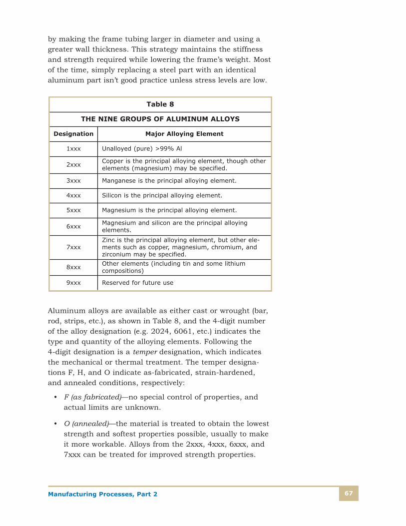
Manufacturing Processes, Part 2 67
by making the frame tubing larger in diameter and using agreater wall thickness. This strategy maintains the stiffnessand strength required while lowering the frame’s weight. Mostof the time, simply replacing a steel part with an identicalaluminum part isn’t good practice unless stress levels are low.
Aluminum alloys are available as either cast or wrought (bar,rod, strips, etc.), as shown in Table 8, and the 4-digit numberof the alloy designation (e.g. 2024, 6061, etc.) indicates thetype and quantity of the alloying elements. Following the 4-digit designation is a temper designation, which indicatesthe mechanical or thermal treatment. The temper designa-tions F, H, and O indicate as-fabricated, strain-hardened,and annealed conditions, respectively:
• F (as fabricated)—no special control of properties, andactual limits are unknown.
• O (annealed)—the material is treated to obtain the loweststrength and softest properties possible, usually to makeit more workable. Alloys from the 2xxx, 4xxx, 6xxx, and7xxx can be treated for improved strength properties.
Table 8
THE NINE GROUPS OF ALUMINUM ALLOYS
Designation Major Alloying Element
1xxx Unalloyed (pure) >99% Al
2xxx Copper is the principal alloying element, though otherelements (magnesium) may be specified.
3xxx Manganese is the principal alloying element.
4xxx Silicon is the principal alloying element.
5xxx Magnesium is the principal alloying element.
6xxx Magnesium and silicon are the principal alloying elements.
7xxxZinc is the principal alloying element, but other ele-ments such as copper, magnesium, chromium, andzirconium may be specified.
8xxx Other elements (including tin and some lithium compositions)
9xxx Reserved for future use
Manufacturing Processes, Part 268
• H (strain hardened)—the material is cold-worked undercontrolled conditions to improve strength and hardnessfor the 1xxx, 3xxx, and 5xxx series. The H is followed by a number such as 12, 14, 16, or 18 to indicate progressively stronger conditions.
• T (heat treated)—the material undergoes a controlledheating and cooling process to obtain specific propertiesfor the 2xxx, 4xxx, 6xxx, and 7xxx groups of alloys. Theletter T is followed by a number that indicates the specif-ic process, such as T4 and T6, for common mechanicaland structural components.
Other common designations you’ll see often are T3—solutionheat treated, cold worked, and age hardened; and T6—solutionheat-treated and artificially aged. Among the most commonforms of aluminum alloys used for manufacturing are thethree wrought types 2024–T4 (UNS A92024), 6061–T4 (UNSA96061), and 7057–T6 (UNS A97075).
A new series of aluminum-lithium alloys has been producedrecently that offers even lower densities and higher specificstrengths. The alloy 2090, for example, contains 2.7 percentcopper, 2.25 percent lithium, 0.25 percent magnesium, and0.12 percent zirconium; it has a yield strength of 66,000 psi.Alloys such as these are expensive to produce, making themsuitable only for critical applications such as aircraft structures.
Copper
Copper and its alloys have been used for thousands of years,and copper remains one of the most useful metals in civiliza-tion today. Pure copper is an extremely good conductor ofheat and electricity, and is essential in the production of elec-trical machinery and electrical transmission and distributionequipment. It’s soft and easily drawn and shaped, but is alsovery difficult to machine. It’s corrosion resistant in manyenvironments, particularly atmospheric air and seawater.Pure copper can be cold-worked to harden it, and is readilyannealed to soften it for further mechanical operations.

Manufacturing Processes, Part 2 69
Brasses and bronzes are the two most common alloy groups.Brasses are copper alloys with zinc as the primary alloyingelement. Brasses are relatively soft and ductile, and easilycold-worked. Brass alloys are used for structural as well asdecorative purposes, and since they’re resistant to corrosionfrom water and chemical environments. Brass is often used forhousehold fixtures in sinks and bathrooms and in many navalapplications because of its resistance to seawater corrosion.
Zinc Alloys
Zinc is one of the most commonly used metals in the world,used principally as a galvanizing coating for fasteners andsteel products. Large quantities are also used for cast partssuch as small gears, levers, and bearing materials. Zinc isattractive because the pressure die-casting process, whichyou’ll learn more about later, can produce finished parts withhigh dimensional accuracy and good surface finishes thatresist corrosion.
Zinc alloys often have small amounts of aluminum and magnesium, and sometimes copper and nickel. One of themost popular alloys of zinc is called Zamak 3, which has 4percent aluminum and 0.035 percent magnesium. Zamak 3and a similar alloy, Zamak 5, are used extensively for cast products.

Manufacturing Processes, Part 270
Self-Check 3
Please fill in the correct answer.
1. Two broad categories of metals are ______________ and _______.
2. The regular arrangement of metallic atoms bonded together in a solid material is know as the__________ structure.
3. As a metal solidifies, crystals begin growing at _________, and grow until the crystals runinto each other, forming __________.
4. A change in crystal structure due to a temperature change is called a _____________ change.
5. Steel with a carbon content of less than 30 points is called __________ steel.
6. Quenching a steel alloy with more than 1 percent carbon content will produce a very hardstructure known as __________.
7. A heat treatment process that restores grain structure to a near-original condition so that further processing can occur is called ___________.
8. Annealing will make a metal more ______________ and more easily worked in stamping orforging operations.
9. Aluminum is a common manufacturing material that’s very strong but only about __________the density of steel.
10. _______ is a process of converting a surface layer of aluminum into a ceramic material, whichis often colored for decorative purposes.
11. In 6061 aluminum, _____________ and _______ are the major alloying elements.
12. __________ alloys are used extensively for die-cast products because of the high quality offinished parts.
Check your answers with those on page 100.

Manufacturing Processes, Part 2 71
NONMETALLIC MATERIALS FORMANUFACTURING
Ceramics
The word ceramics is derived from the Greek word keramikos,which means “burnt substance” and refers to the firing of theraw material, clay. The common usage of the term ceramicapplies to products such as pottery or materials made fromclay. However, the manufacturing material terminology hasexpanded to include virtually all inorganic nonmetallic materials.In manufacturing operations, ceramics are used for abrasivematerials, electrical insulators, cutting tool edges, refractoryfixtures—even armor.
Ceramics are usually crystalline and are compounds formedbetween metals and non metals, typically oxides, carbides,and nitrides, such as the industrial ceramics alumina (Al2O3),titanium nitride (TiN), and silicon nitride (Si3N4). The bondsbetween atoms in these crystals can range from stronglyionic, as in calcium fluoride (CaF2), to strongly covalent, as insilicon carbide (SiC). Ceramics retain their strength at hightemperatures. Zirconium dioxide has a bend strength similarto steel but retains it to over 900ºC. Silicon carbide and sili-con nitride retain their strength at well over 1400ºC, makingthem excellent materials for high-temperature applicationssuch as turbine engine blades. Densities of ceramics can varygreatly depending on manufacturing techniques. They’re usu-ally hard and brittle, with great compressive strength but lowtensile and shear strength. Because of their hardness andstability, they’re often used as coatings for tools as well asprotective coatings. Ceramics are broadly categorized by theceramic industry into the groups shown in Table 9.

Manufacturing Processes, Part 272
Ceramic Manufacturing
In general, ceramics are produced by the application of heaton pressed clay or other powdered raw materials in “green”form. The powders are obtained either from minerals that arecrushed and ground, or from purified powders that are fil-tered and sized. The green form is made by adding binders orwater to ceramic particles. It’s then shaped into the desiredform by casting, extruding, pressing, or injection molding.Heating—sometimes called firing or sintering—drives off mois-ture or binding material and fuses the ceramic particles intoa hard, solid final shape. For some applications, the nextstep is a glazing operation.
Table 9
CERAMIC MATERIAL CLASSIFICATIONS
Category Example Applications
Structural clay products Brick, roofing tile, flue liners, floor andwall tile
Whitewares Dinnerware, floor and wall tile, decorativeceramics, electrical insulators
RefractoriesBricks and large-block products used inmanufacturing, chemical and constructionindustries
Glasses Flat glass, glass containers, glass fibers,optical fibers, blown and pressed glass
AbrasivesNatural abrasives (diamond, garnet), syn-thetic abrasives (silicon carbide, diamond,alumina)
Cements Concrete roads, bridges, building decks,dams
Advanced Ceramics—Structural
Bioceramics, cutting tools, engine components
Advanced Ceramics—Electrical
Capacitors, insulators, magnets, supercon-ductors, piezoelectrics, integrated circuitsubstrates
Advanced Ceramics—Coatings
Cutting-tool wear coatings, engine components
Advanced Ceramics—Chemical
Filters, catalysts, catalyst supports, membranes

Manufacturing Processes, Part 2 73
Glass is considered to be a type of ceramic, and is manufac-tured by melting ingredients such as silica, lime, and ashand then forming into the desired shape while still molten.The molten glass is quickly cooled and “frozen” in place, andusually undergoes additional processes such as temperingand heat-treating.
Ceramic materials can have either ionic or covalent bondingand can be crystalline or amorphous—meaning without anyregular structure. Ceramic materials will tend to fracturebefore any significant deformation occurs, and thus aren’tconsidered tough materials.
Ceramic products can be formed from several processes:
• Slip casting—a process that uses molds that have porouswalls. The molds are filled with water, and the ceramicpowder is added to the mold as the water is allowed toflow out. The ceramic powder sticks to the walls to forma solid green ceramic part, which is fired to harden.
• Pressure casting—a process that uses pressure to forceceramic powder into a mold and form a solid ceramiclayer on the inside.
• Injection molding—the ceramic powder is pressed into amold through a heated tube with the use of pressurefrom a piston or extrusion screw machine. The powdercools and hardens, and the green ceramic is removedfrom the mold and then fired.
• Extrusion—ceramic powder is heated in a long tube andforced out a nozzle with a desired shape (a die) in a con-tinuous operation. As the ceramic powder leaves the die,it’s cut to the desired length. Extrusion is used to formceramic shapes such as tubes, rods, tiles, and bricks.
After the ceramic parts are formed, they’re heated at temper-atures up to 1700ºC for densification, as shown in Figure 28.The powder particles adhere to each other and shrink as muchas 20 percent, resulting in a denser and stronger material.Ceramics can have different densities for different applications.

Manufacturing Processes, Part 274
For example, ceramics used for vacuum-tube parts are madefrom high-density (> 99 percent) alumina, while ceramicinsulators used for electrical applications can be less densewithout affecting performance.
Ceramic Applications
Ceramic materials have been used in manufacturing forthousands of years, but within the last 50 years material sciences have yielded especially marked advances in what areknown as technical ceramics. These ceramics can be producedin forms that are electrical conductors or insulators; magneticor nonmagnetic; and thermal conductors or insulators. Amore thorough understanding of their structure and theeffects of impurities has made their processing and produc-tion more reliable and efficient, and their properties moreeasily manipulated for special applications.
Mechanical applications use the inherent hardness andstrength of ceramic materials. Ceramics are used for abrasives,the most popular and important being silicon carbide, alsocalled carborundum. Aluminum oxide and boron carbide arealso used. Boron carbide is one of the hardest materialsknown, and is used to make saw blade tips and drill bit tips.Many of the cutting tools in a manufacturing shop will have ayellow coating of titanium nitride (TiN), an extremely hardsubstance that extends the tool life many times for a smallincrease in cost. The TiN coating on the tool bits shown inFigure 29 is only about 0.0001 inch thick but offers significantadvantages in high-speed machining. Silicon carbide, siliconnitride, and some zirconias are used to make parts for high-temperature products such as turbine blades, rotors, andengine valves.
Pore Grain Boundary
NeckApplication of HeatFIGURE 28—“Green”
ceramic shapes are heat-ed at high temperaturesuntil the particles adherein a denser form.

Manufacturing Processes, Part 2 75
Ceramics can be made that are insulators, semiconductors,and conductors for electrical applications. Aluminum oxide isused to produce high-voltage insulators, and because of itsthermal stability, it’s used to make substrates—ceramic plat-forms for miniature circuitry—for integrated circuits. Theinsulating property is used in many high-voltage applicationssuch as the image intensifier shown in Figure 30.
Semiconductive ceramics such as barium titanate and strontium titanate are used to make the extremely smalltransistors in integrated circuits as well as capacitors withvery high capacities in small volumes. A copper oxide ceramiccan be superconductive—able to conduct electricity with noresistance—at temperatures high enough to have importantcommercial applications. (Previously, superconductivity was
FIGURE 29—Tool life is greatly extended by applying a thin, extremely hard titanium nitride coating.The tool bits are coated on their cutting edges, which gives them a recognizable yellow coloring.

Manufacturing Processes, Part 276
a phenomenon that occurred only at temperatures close to absolute zero, which made it impractical for commercialproducts.) Ferrites are ceramics with iron oxides that makethem magnetic. Ferrites are used in radio-frequency andmicrowave communication devices such as radio and videosystems. Ferrites are also the recording media for audio andvideo recording tapes and computer floppy disks. Ceramicscan also be made to produce piezoelectricity, which is an electric voltage created by pressure applied to a ceramic.Piezoelectric ceramics are used in microphones and speakers,ultrasonic transducers, and igniters for “electric matches,”gas grills, ovens, furnaces, and welding equipment.
Ceramics are used to make components for biomedical usesin human and animal bodies. Some ceramics are compatiblewith human tissue and will bond with bone and other tissues.Ceramics are used to make hip joints, dental caps, and bridges.
FIGURE 30—This imageintensifier, used in night-vision devices, makesextensive use of ceram-ic’s ability to withstandhigh temperatures, insu-late high voltages, andprovide vacuum-tightseals with metals.

Manufacturing Processes, Part 2 77
Finally, ceramics are especially important for structural andbuilding applications. Modern buildings are full of variousceramic materials, using clay and shale as the raw materials,including bricks, tile, cement, and specialty glasses. Plumbingfixtures, water pumps and seals (as shown in Figure 31),kitchen appliances, and cookware all use ceramics of varioustypes that offer strength, abrasion resistance, hardness, andthe ability to withstand high temperatures.
Polymers
Naturally occurring polymers include materials such aswood, rubber, cotton, wool, and silk and have been usedsince the dawn of time. As modern scientific research hasrevealed the structure of these molecules, many synthetic
FIGURE 31—This pump seal is made from a hard-glazed ceramic face (the white disk) that seals a rotating polymer matrix seal (the black ring). The seal will function for thousands of hours in harsh environments.

Manufacturing Processes, Part 278
polymers have been developed. World War II was an especiallypowerful stimulus for the development of synthetic materialsto substitute for scarce natural polymers such as rubber andwood. Synthetic polymers are now very common and can beproduced inexpensively, with properties tailored for specificapplications. Polymers are produced mostly from petroleumor natural gas. They’re attractive materials for manufacturingproducts because
• They’re less dense than metals or ceramics.
• They’re excellent electrical insulators.
• They can be used in medical applications because they’recompatible with human tissue (the body doesn’t rejectthe material as foreign organisms as in the case of anartificial heart).
• They’re resistant to corrosion from atmospheric conditionsor chemicals.
Polymers can be divided generally into two groups, thermo-plastics and thermosetting plastics. Thermoplastic polymerscan be melted and formed into shapes, by injection molding,for example. Some commodity thermoplastics are polyethylene,polypropylene, polystyrene, and polyvinyl chloride, which we’lldiscuss in this section. Thermoplastics can be remelted andreprocessed many times, within reason, as each heat cycledegrades the material and reduces its properties. Thermoplasticpolymers are therefore easily recyclable. Parts using thermo-plastic polymers are fabricated by heat and pressure. Injectionmolding uses small plastic beads that are melted and forcedinto a mold. Extrusion is also used for fabrication of suchitems as hoses, drinking straws, pipes and ropes.
Thermosetting plastics can’t be remelted without destroyingthe material. Examples of thermosetting plastics includealkyds, phenolic resins, polyurethanes, and some polyesters.When thermosetting polymers are heated they become per-manently hard; subsequent heating won’t remelt them. Theheating process forms covalent cross-links with adjacentpolymer strands, making the final material more rigid, harder, and stronger, with superior dimensional stability.Some examples of thermosetting polymers include vulcanizedrubbers, epoxies, phenolic resins, and polyester resins.
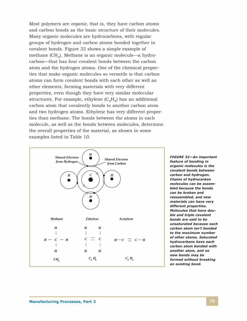
Manufacturing Processes, Part 2 79
Most polymers are organic, that is, they have carbon atomsand carbon bonds as the basic structure of their molecules.Many organic molecules are hydrocarbons, with regulargroups of hydrogen and carbon atoms bonded together incovalent bonds. Figure 32 shows a simple example ofmethane (CH4). Methane is an organic molecule—a hydro-carbon—that has four covalent bonds between the carbonatom and the hydrogen atoms. One of the chemical proper-ties that make organic molecules so versatile is that carbonatoms can form covalent bonds with each other as well asother elements, forming materials with very different properties, even though they have very similar molecularstructures. For example, ethylene (C2H4) has an additionalcarbon atom that covalently bonds to another carbon atomand two hydrogen atoms. Ethylene has very different proper-ties than methane. The bonds between the atoms in eachmolecule, as well as the bonds between molecules, determinethe overall properties of the material, as shown in someexamples listed in Table 10.
C
H
HH
H
Shared Electronfrom Hydrogen Shared Electron
from Carbon
Methane
H
H H
H
——
——
C
CH4
H
H
——
C
H
H
——
C
C2 H4
Ethylene Acetylene
H—CC—H—— —
—–
C2 H2
FIGURE 32—An importantfeature of bonding inorganic molecules is thecovalent bonds betweencarbon and hydrogen.Chains of hydrocarbonmolecules can be assem-bled because the bondscan be broken andreassembled, and newmaterials can have verydifferent properties.Molecules that have dou-ble and triple covalentbonds are said to beunsaturated because eachcarbon atom isn’t bondedto the maximum numberof other atoms. Saturatedhydrocarbons have eachcarbon atom bonded withanother atom, and nonew bonds may beformed without breakingan existing bond.

Manufacturing Processes, Part 280
Figure 33 shows how these compounds are “built up” byadding carbon and hydrogen atoms to an existing molecule.
Polymer Molecules
Polymer molecules are long chains of hydrocarbon molecules,sometimes called macromolecules because they’re so largecompared to the individual units from which they’re formed.The name polymer is derived from “poly,” meaning many, and“mer,” which comes from a Greek word meaning “part.” Apolymer is a molecule composed of many individual partscalled monomers. The manufacturing of polymers is donebasically with chemical reactions that cause individualhydrocarbon molecules to bond together. In the individualmolecules, wherever carbon has formed a double or triplebond that can be broken, it’s possible to link additional
Table 10
SOME HYDROCARBON STRUCTURES
Paraffin Hydrocarbon Structures CnH2n+2
Name Composition Boiling Point — ºC
Methane CH4 –164º
Ethane C2H6 –88.6º
Propane C3H8 –42.1º
Butane C4H10 –0.5º
Pentane C5H12 36.1
Hexane C6H14 69.0º
Methane
H
H H
H
——
——
C
CH4
H
H
——
C
H
H
——
C
C2 H6
Ethane Propane
——H — H
H
H
——
C
H
H
——
C
C3 H8
——H — H
H
H
——
C—
FIGURE 33—Members ofthe paraffin hydrocarbongroup have similar structures and chemicalformulas, but have verydifferent propertiesdepending on the number of carbon andhydrogen atoms in thechain.
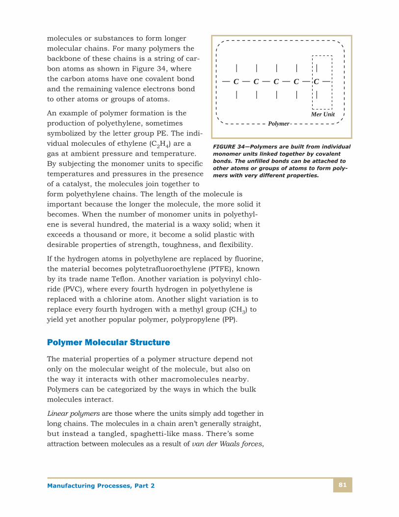
Manufacturing Processes, Part 2 81
molecules or substances to form longermolecular chains. For many polymers thebackbone of these chains is a string of car-bon atoms as shown in Figure 34, wherethe carbon atoms have one covalent bondand the remaining valence electrons bondto other atoms or groups of atoms.
An example of polymer formation is theproduction of polyethylene, sometimes symbolized by the letter group PE. The indi-vidual molecules of ethylene (C2H4) are agas at ambient pressure and temperature.By subjecting the monomer units to specifictemperatures and pressures in the presenceof a catalyst, the molecules join together toform polyethylene chains. The length of the molecule isimportant because the longer the molecule, the more solid itbecomes. When the number of monomer units in polyethyl-ene is several hundred, the material is a waxy solid; when itexceeds a thousand or more, it become a solid plastic withdesirable properties of strength, toughness, and flexibility.
If the hydrogen atoms in polyethylene are replaced by fluorine,the material becomes polytetrafluoroethylene (PTFE), knownby its trade name Teflon. Another variation is polyvinyl chlo-ride (PVC), where every fourth hydrogen in polyethylene isreplaced with a chlorine atom. Another slight variation is toreplace every fourth hydrogen with a methyl group (CH3) toyield yet another popular polymer, polypropylene (PP).
Polymer Molecular Structure
The material properties of a polymer structure depend notonly on the molecular weight of the molecule, but also on the way it interacts with other macromolecules nearby.Polymers can be categorized by the ways in which the bulkmolecules interact.
Linear polymers are those where the units simply add together inlong chains. The molecules in a chain aren’t generally straight,but instead a tangled, spaghetti-like mass. There’s someattraction between molecules as a result of van der Waals forces,
——
C ——
——
C —
——
C —
——
C —
——
C—
Mer UnitPolymer
FIGURE 34—Polymers are built from individualmonomer units linked together by covalentbonds. The unfilled bonds can be attached toother atoms or groups of atoms to form poly-mers with very different properties.

Manufacturing Processes, Part 282
but most of the molecules are essentially independent of eachother. Linear polymers include polyethylene, polyvinyl chloride,polystyrene, nylon, and the fluorocarbons.
Branched polymers have side branches connected to the lin-ear part of the molecule. These branches may be caused byimpurities or by formation with monomers that have differentreactive groups. These polymers have lower density than thelinear polymers. Examples of branched polymers include soft, flexible plastics such as plastic food wrap and ketchupsqueeze bottles.
Cross-linked polymers have molecules that have multiple connection sites to other chains. These connections occur in three dimensions, and cross-linking is achieved by nonreversible chemical reactions at high temperatures.Thermosetting plastics are highly cross-linked, and as aresult tend to decompose or burn rather than melt. In asense, they can be thought of as one giant molecule. A highlycross-linked polymer is sometimes classified as a networkedpolymer. Diagrammed examples of these structures areshown in Figure 35.
Linear
Branched Networked
Cross-Linked
FIGURE 35—Polymerscan be linked in severalways that have signifi-cant effects on proper-ties. Linear polymersare long, relativelystraight chains.Branched polymershave linear branches atirregular intervals, withunlinked branches orig-inating from the mainchain. Cross-linkedpolymers have multipleconnections to otherchains. Networked poly-mers are consideredhighly cross-linkedpolymers.
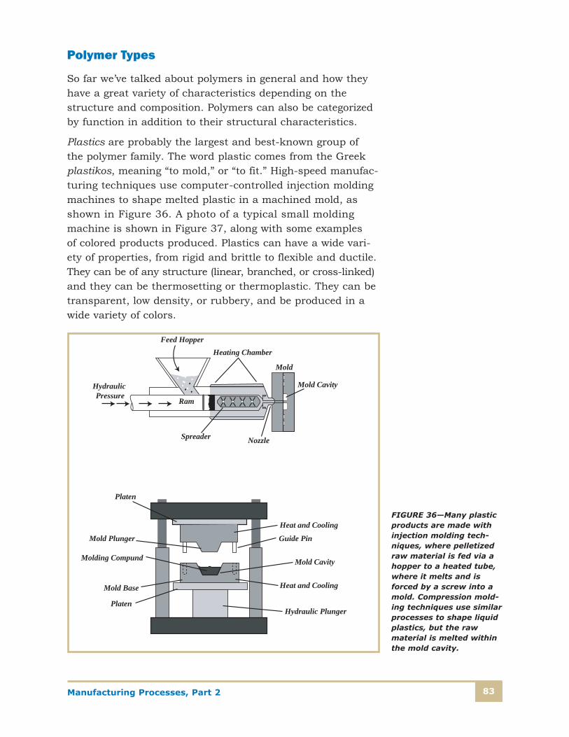
Manufacturing Processes, Part 2 83
Polymer Types
So far we’ve talked about polymers in general and how theyhave a great variety of characteristics depending on thestructure and composition. Polymers can also be categorizedby function in addition to their structural characteristics.
Plastics are probably the largest and best-known group of the polymer family. The word plastic comes from the Greekplastikos, meaning “to mold,” or “to fit.” High-speed manufac-turing techniques use computer-controlled injection moldingmachines to shape melted plastic in a machined mold, asshown in Figure 36. A photo of a typical small moldingmachine is shown in Figure 37, along with some examples of colored products produced. Plastics can have a wide vari-ety of properties, from rigid and brittle to flexible and ductile.They can be of any structure (linear, branched, or cross-linked)and they can be thermosetting or thermoplastic. They can betransparent, low density, or rubbery, and be produced in awide variety of colors.
NozzleSpreader
Feed Hopper
Ram
Heating Chamber
Mold
Mold CavityHydraulic Pressure
Heat and Cooling
Platen
Mold Plunger
Mold Base Heat and Cooling
Guide Pin
Molding Compund Mold Cavity
PlatenHydraulic Plunger
FIGURE 36—Many plasticproducts are made withinjection molding tech-niques, where pelletizedraw material is fed via ahopper to a heated tube,where it melts and isforced by a screw into amold. Compression mold-ing techniques use similarprocesses to shape liquidplastics, but the rawmaterial is melted withinthe mold cavity.
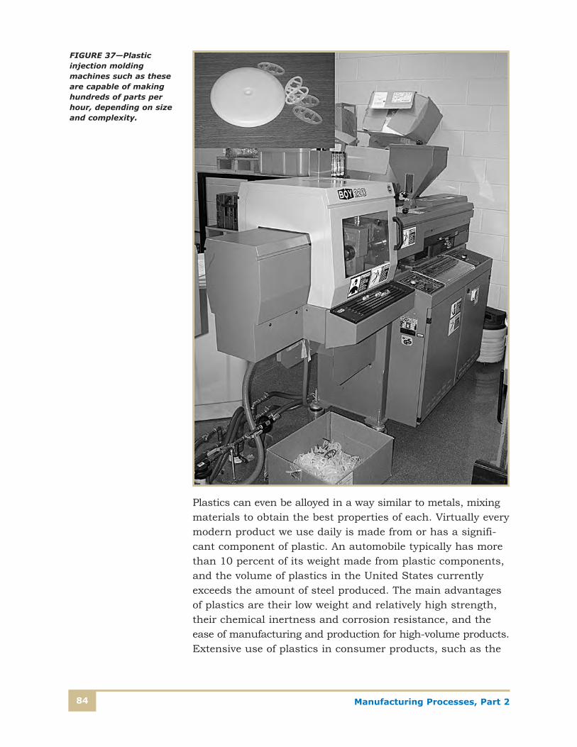
Manufacturing Processes, Part 284
Plastics can even be alloyed in a way similar to metals, mixingmaterials to obtain the best properties of each. Virtually everymodern product we use daily is made from or has a signifi-cant component of plastic. An automobile typically has morethan 10 percent of its weight made from plastic components,and the volume of plastics in the United States currentlyexceeds the amount of steel produced. The main advantagesof plastics are their low weight and relatively high strength,their chemical inertness and corrosion resistance, and theease of manufacturing and production for high-volume products.Extensive use of plastics in consumer products, such as the
FIGURE 37—Plastic injection moldingmachines such as theseare capable of makinghundreds of parts perhour, depending on sizeand complexity.
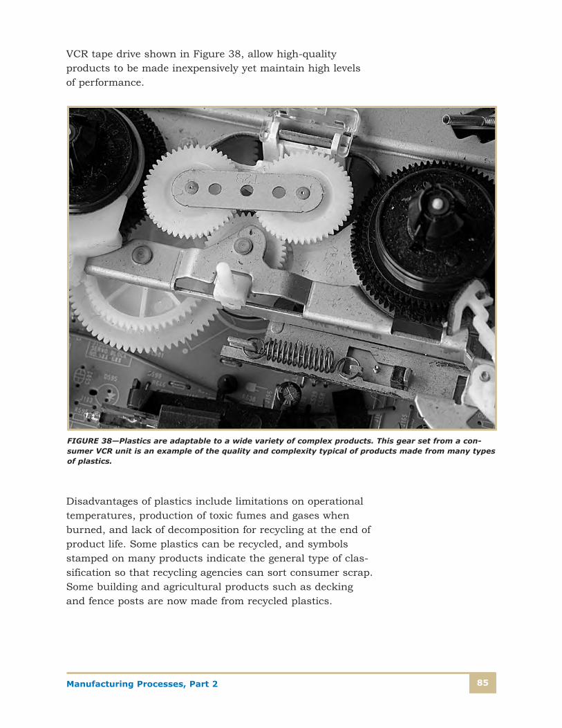
Manufacturing Processes, Part 2 85
VCR tape drive shown in Figure 38, allow high-quality products to be made inexpensively yet maintain high levels of performance.
Disadvantages of plastics include limitations on operationaltemperatures, production of toxic fumes and gases whenburned, and lack of decomposition for recycling at the end ofproduct life. Some plastics can be recycled, and symbolsstamped on many products indicate the general type of clas-sification so that recycling agencies can sort consumer scrap.Some building and agricultural products such as deckingand fence posts are now made from recycled plastics.
FIGURE 38—Plastics are adaptable to a wide variety of complex products. This gear set from a con-sumer VCR unit is an example of the quality and complexity typical of products made from many typesof plastics.

Manufacturing Processes, Part 286
Elastomers are polymers that have very high elasticity, withthe ability to snap back into their original shape when theforce is removed. Rubber is one of the natural elastomers forwhich many synthetic polymers were derived as replacements.The molecular structure of elastomers is amorphous, whichmeans their molecules are randomly arranged of molecules.The polymer chains are coiled, twisted together, and kinked;a tensile force causes the stretching and uncoiling andstraightening of the molecules. When the force is removed,the elastomer returns to its original shape.
Elastomers can be strengthened and hardened by a processcalled vulcanization, where sulfur is added to the polymer atelevated temperatures, which cause the polymer chains tocross-link through the sulfur molecules. Typical mixtures are upto 5 parts sulfur to 100 parts elastomer by weight. Automobiletires are vulcanized for hardness and strength, to make themcapable of handling loads with reasonable wear characteristics.Elastomers are used in many types of machinery and products,especially as gaskets and seals, pneumatic tires and tubes,wire and cable coverings, and tank linings.
Fiber polymers have the ability to be drawn into long fibershaving at least a 100:1 length-to-diameter ratio for use incomposites as reinforcement materials or to be woven intotextiles. Fibers used for these applications must have a hightensile strength and the ability to resist abrasion, since theweaving process involves pulling, twisting, cutting, and sliding. Nylon, a polyamide, has been popular for a variety offiber applications including clothing (such as stockings) andcomposite reinforcement.
Other polymer applications include coatings, adhesives, films,and foams. Coatings are added to a product’s exterior layerfor protection, decoration, or for electrical insulation. Organicpolymers are often used for coating applications, such aspaint, varnish, enamel, lacquer, and shellac. Polymer adhe-sives are also an important application because they canbond metal-to-metal, metal-to-ceramic, metal-to-plastic, andmetal-to-glass, as well as other materials. Engineered adhe-sives are used for product assembly in many applications,but these adhesives are limited in the temperatures at whichthey can operate.
Manufacturing Processes, Part 2 87
Polymers are also used as films for packaging such items as food, electronic products, textiles, and other products.Shrinkwrap is popular in packaging manufactured products,and is produced from polymers such as polyvinyl chloride,polyethylene, polypropylene, and cellophane. Polymer foamsare also used extensively for packaging and other applications.Foams have many small pores within the material, giving it avery low density and moderately high strength. Foams areproduced from polyurethanes, rubbers, polyvinyl chloride,and polystyrene, and are of the thermosetting variety.
Table 11 shows a summary of some of the most commontypes of plastics and their typical applications. Plasticsresearchers continuously strive to develop new and betterplastics and polymers, as well as cheaper production methods,to supply future needs.
Composites
Composites are engineered materials that are composed of twoor more substances that retain their individual characteristics,and when combined, make a new material that has proper-ties that can’t be achieved by any of them separately. Manycommon materials can be considered composites: concrete is amixture of Portland cement and stone aggregate; plywood is amixture of wood laminates and adhesives; and fiberglass is amixture of glass fibers and a plastic polymer. A major reasonfor manufacturing composites is to achieve higher strengthwhile retaining some of the desirable properties of the basematerial. Composites thus have a base, or bulk material,called the matrix, and a reinforcing material embedded withinthe matrix. The reinforcing material is the principal source ofthe composite’s strength. For example, fiberglass is a flexible-matrix polymer made much stronger with the addition ofglass fibers. The desirable qualities of the polymer—flexibility,resistance to chemicals, and low density—are retained in amaterial that’s much higher in strength.
Manufacturing Processes, Part 288
Table 11
PLASTIC PROPERTIES AND APPLICATIONS
Material Properties Applications
Thermoplastic Types
Polyethylene (PE)Clear; permeable by hydrocarbons,alcohol, and gas; resistant to chemicals
Film, general-purpose bags, pipeand tubing, insulating sleeves,bottle stoppers, lids, food wrap,toys
Polypropylene (PP)Low density; durable, permeable bywater; impact resistant and tempera-ture resistant to 135 degrees C
Household items, plastic wrap,automobile parts, outdoor furniture, syringes, bottles, appliances
Polystyrene (PS)Transparent; nontoxic; good opticaland electrical properties; easy tocolor; resistant to oils and greases
Food and packaging wrap,kitchen utensils, thermal insula-tion, toys, office supplies, dispos-able razors, bottles
Polyvinyl Chloride(PVC)
Can be made soft or rigid; opaque ortransparent; fire resistant, resistantto acids, bases, oils, grease, andalcohols
Household items, electric wireinsulation, water pipes, baggage,vinyl, sport and camping gear,items for chemical and automo-bile industries
Polytetrafluoroethyl-ene (PTFE), or Teflon
Chemically inert, anti-adhesive,impermeable to water and grease,heat; corrosion resistant, low frictioncoefficients, good electrical properties
Medical appliances and equip-ment, joints, corrosion-resistantmechanical parts, electrical insulation, cookware coatings
PolymethylMethacrylate(PMMA), or Plexiglas
Good optical properties, ages well,weather resistant
Glass substitutes, windows, portholes, optical fibers, contactlenses
Polyamides (PA)(Nylon)
Good mechanical properties, durableto temperatures of 100ºC, resistantto x-rays and fuel, impermeable toodors and gas
Food wrap, fuel pipes, shoes, skibindings, bicycle seats, gears,bearings, clothing
Thermoset Types
Polyesters
Thermosetting, transparent, mechan-ical properties at high temperatures,electrical properties, resistant toimpact, easy to work with
Textiles, plastic wrap, bottles,switches, electric sockets andfuses, appliances, clothing, hel-mets, boat hulls, auto-body parts
PhenolicsHigh rigidity, moldability; good elec-trical properties, excellent high-temperature properties (to 150ºC)
Varnish, electrical insulators and fixtures, motor housings,telephones
(Continued)
Manufacturing Processes, Part 2 89
The three major categories of composites are metal-matrixcomposites (MMCs), ceramic-matrix composites (CMCs), andpolymer-matrix composites (PMCs).
Production of composites is a labor-intensive process, sincemany of the techniques involve layering, winding, or otherwiseorienting the fibers or reinforcement materials in particulardirections. The promise of high strength and low weight,however, continues to spur new developments in this area,particularly in what’s known as advanced composites. Asmanufacturing techniques and materials improve, compositeswill gain wider applications in manufacturing. Table 12shows a summary of composite matrix and reinforcementmethods commonly used today.
Reinforcement Materials
Table 12 shows the different classifications of reinforcementprocesses. Remember, composites are bulk, or matrix, mate-rials that are reinforced using one of three methods thatincrease the strength, stiffness, or other desirable properties.Different types of PMCs, MMCs, and CMCs can use any of thefollowing techniques, illustrated in Figure 39, for reinforcement.
Table 11—Continued
Material Properties Applications
Thermoset Types
Urea-Formaldehyde(UF) Clear, easy to form Glass replacements, dishes
EpoxiesGood mechanical properties, corro-sion resistant, dimensionally stable,good electrical properties
Electrical insulation and parts,adhesives, protective coatings,fiberglass laminates
Other Types
Silicone Fluid, resistant to adhesives
Fluid for electrical transformers,putty, molding, anti-adhesivecoatings, varnish, wax, burntreatments, cosmetic surgery,lubricants

Manufacturing Processes, Part 290
Table 12
COMPOSITE MATERIAL CLASSIFICATIONS AND STRUCTURES
Composite Material Structures
Matrix Materials
Metals
Ceramics
Polymers
Reinforcement Materials
Fibers and particles such as: Glass,silicon carbide, ceramic, carbon,boron, metals,
Kevlar (polymer)
Reinforcement Methods
Fiber-reinforced composites
Dispersion-reinforced composites
Particle-reinforced composites
Matrix
Fiber
Matrix
Particles
Matrix
Dispersion Particles
Fiber Reinforced Particle Reinforced
Dispersion Strengthened
FIGURE 39—Compositematrices can be rein-forced with three typesof materials: fibers, smalldispersion-hardeningmaterials such as oxides,and larger particle rein-forcements. Matrices canbe metals, polymers, orceramics.

Manufacturing Processes, Part 2 91
The most common fiber reinforcement is fiberglass, but car-bon fibers and aramid (a polymer similar to nylon) fibers arealso among those used. The fibers can be long and continu-ous or short, particles, or woven sheets. Fibers can be addedto brittle materials such as ceramics to improve toughness orthey can be added to ductile metals to increase strength andstiffness. The final properties of the composite will be deter-mined by the length-to-diameter ratio of the fibers, theamount of fibers by volume present in the matrix, and thestrength of the interface between the fiber and the matrix.
Popular fiber materials include
• Glass—glass has relatively low density and a high tensilestrength. It’s usually used with polymer matrix materials.Glass fibers are relatively inexpensive, easily obtainable,and easy to fabricate within composite materials.
• Carbon-graphite—carbon fibers are extremely useful, andare being used in composite materials in everything fromgolf clubs to rifle barrels. Carbon is very light and muchstiffer than glass, with up to 15 times the strength ofcarbon steel. Carbon fibers are made of densely packedhexagonal layers in a graphite-like structure that’s rela-tively easy to form. Carbon fiber composites have highlyanisotropic properties, and strength and stiffness in spe-cific directions can be controlled by how the fibers areoriented within the matrix. Layers oriented in differentdirections can be used to make the material propertiesmore uniform.
• Polymer—polymer fibers can have strong covalent bondsin the fiber itself and between other fibers in the matrix.Kevlar is a well-known polymer fiber consisting of orientedaramid chains that have extremely high tensile strength.Kevlar is used in such critical applications as chain-saw-resistant leggings for foresters and body armor forpolice and soldiers.
• Ceramic—ceramic fibers are made from alumina (Al2O3)and silicon carbide (SiC) and are very useful for high-temperature applications. Most of this material is in aparticle form when used for reinforcement.
Anisotropic refers toproperties, such astransmission speed,that vary depending onthe direction of meas-urement. Contrast withisotropic.
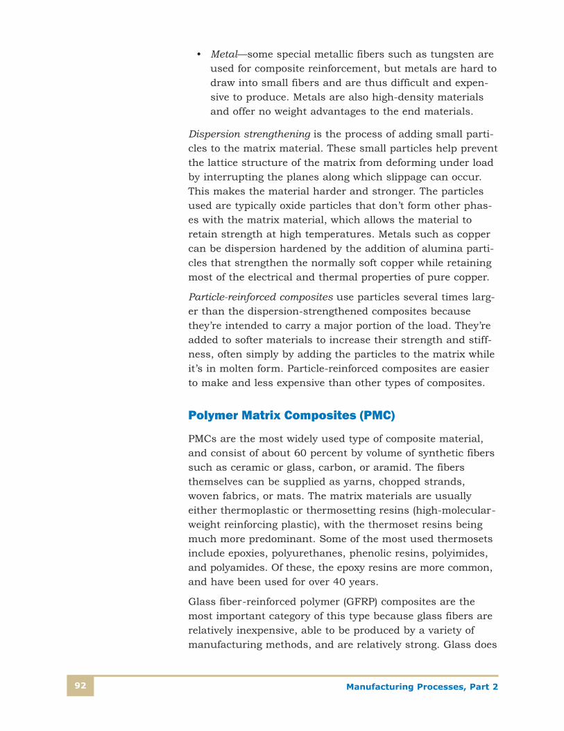
Manufacturing Processes, Part 292
• Metal—some special metallic fibers such as tungsten areused for composite reinforcement, but metals are hard todraw into small fibers and are thus difficult and expen-sive to produce. Metals are also high-density materialsand offer no weight advantages to the end materials.
Dispersion strengthening is the process of adding small parti-cles to the matrix material. These small particles help preventthe lattice structure of the matrix from deforming under loadby interrupting the planes along which slippage can occur.This makes the material harder and stronger. The particlesused are typically oxide particles that don’t form other phas-es with the matrix material, which allows the material toretain strength at high temperatures. Metals such as coppercan be dispersion hardened by the addition of alumina parti-cles that strengthen the normally soft copper while retainingmost of the electrical and thermal properties of pure copper.
Particle-reinforced composites use particles several times larg-er than the dispersion-strengthened composites becausethey’re intended to carry a major portion of the load. They’readded to softer materials to increase their strength and stiff-ness, often simply by adding the particles to the matrix whileit’s in molten form. Particle-reinforced composites are easierto make and less expensive than other types of composites.
Polymer Matrix Composites (PMC)
PMCs are the most widely used type of composite material,and consist of about 60 percent by volume of synthetic fiberssuch as ceramic or glass, carbon, or aramid. The fibers themselves can be supplied as yarns, chopped strands,woven fabrics, or mats. The matrix materials are usuallyeither thermoplastic or thermosetting resins (high-molecular-weight reinforcing plastic), with the thermoset resins beingmuch more predominant. Some of the most used thermosetsinclude epoxies, polyurethanes, phenolic resins, polyimides,and polyamides. Of these, the epoxy resins are more common,and have been used for over 40 years.
Glass fiber-reinforced polymer (GFRP) composites are themost important category of this type because glass fibers arerelatively inexpensive, able to be produced by a variety ofmanufacturing methods, and are relatively strong. Glass does

Manufacturing Processes, Part 2 93
have some limitations, however, that make it suitable only forapplications below about 400ºF, and isn’t strong enough forcritical applications such as aircraft structures. CommonGFRP applications include automobile bodies, boats, archeryequipment, storage containers, and industrial flooring.
Carbon fiber–reinforced polymer (CFRP) composites are theglamour kids of the polymer matrix category. Carbon fibershave the highest strength of all of the currently used fibermaterials, and they retain their strength at fairly high tem-peratures. In addition, they’re resistant to a wide variety ofharsh environments yet are relatively inexpensive and cost-effective. CFRP composites are used in a wide variety ofsports equipment, like golf clubs and fishing rods, but arealso used in critical applications such as rocket motors, air-craft structural components, and pressure vessels. For theseapplications, the fibers are oriented so that the stresses placethe fiber in tension, where carbon fibers are significantlyhigher in strength than any metal alloys.
Aramid fiber–reinforced composites were introduced in theearly 1970s. The most recognizable example of this categoryis Kevlar, which is used as body armor for police and militarypersonnel. Kevlar has the ability to prevent penetration offairly large-caliber weapons at short ranges due to itsextremely high tensile strength. The polymer structure ofKevlar is shown in Figure 40, which shows a large monomerstructure and hydrogen bonding between adjacent polymerchains. Another aramid fiber composite is Nomex, which isused for fire-protection suits. Aramid fiber composites can beprocessed by most textile operations and retain their strengthat high temperatures. They’re also used in sporting equipment,automotive brakes and tires, and ropes. Because fibers havestrength in only one direction, part designs are often opti-mized to take advantage of that, as in golf clubs, skis, riflebarrels, or aircraft structural parts. They can also be built upin layers to achieve strength in more than one direction, asshown in Figure 41.
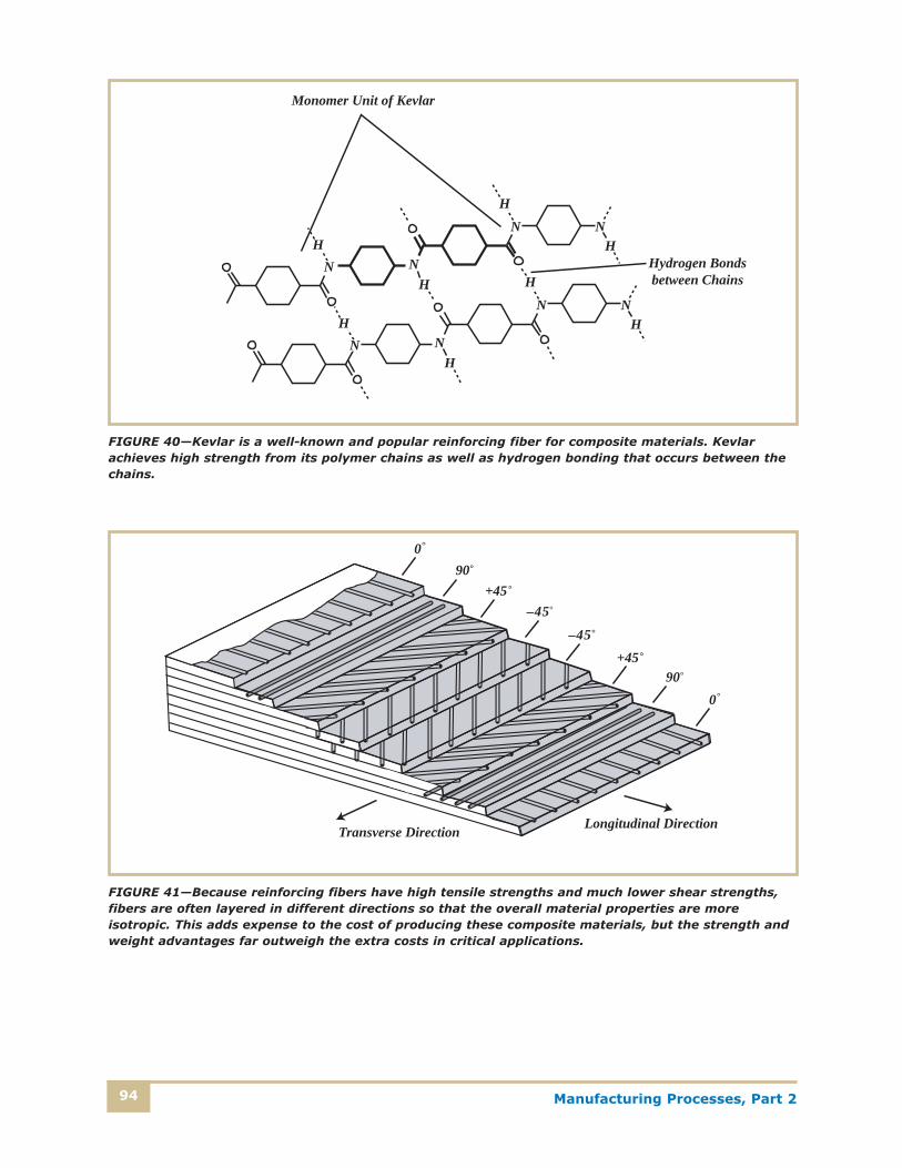
Manufacturing Processes, Part 294
NH
NH
NH
NH
NH
NH
NH
NH
Monomer Unit of Kevlar
Hydrogen Bondsbetween Chains
FIGURE 40—Kevlar is a well-known and popular reinforcing fiber for composite materials. Kevlarachieves high strength from its polymer chains as well as hydrogen bonding that occurs between thechains.
090
+45–45
–45+45
900
Longitudinal DirectionTransverse Direction
FIGURE 41—Because reinforcing fibers have high tensile strengths and much lower shear strengths,fibers are often layered in different directions so that the overall material properties are moreisotropic. This adds expense to the cost of producing these composite materials, but the strength andweight advantages far outweigh the extra costs in critical applications.

Manufacturing Processes, Part 2 95
Metal-Matrix Composites (MMC)
Metal-matrix composites use ductile metals as the matrix, withreinforcing materials designed to increase toughness, strength,stiffness, or hardness. Metal-matrix composites can be usedat higher temperatures than polymer-matrix composites.Reinforcement may improve specific properties of the matrix,but they’re usually more expensive than PMCs. MMCs can bereinforced with carbon, boron, silicon carbide, refractory metalssuch as molybdenum or tungsten, and alumina. These materi-als can be added in proportions up to 60 percent by volume,and can be continuous fibers of carbon, boron, alumina, andrefractory metals; discontinuous fibers of silicon carbidewhiskers, chopped alumina or carbon; and particles of siliconcarbide and alumina. The different types of reinforcements willdictate the final processing of the parts. Discontinuous fiberscan be formed by most common manufacturing operationssuch as forging, rolling, or extrusion.
Metal-matrix composites are used extensively by the automo-tive industry in products such as aluminum-alloy enginecomponents reinforced by alumina and carbon fibers, driveshafts, and suspension components. Aircraft and spacecraftapplications include structural components with aluminumalloy MMCs using boron and carbon fibers. Turbine engineparts are enhanced by reinforcement of the nickel- andcobalt-based alloys with refractory metals such as tungstenand molybdenum.
Ceramic Matrix Composites (CMC)
One of the chief advantages of ceramic materials is their ability to operate at high temperatures. However, they’re sus-ceptible to brittle fracture and are often weak in tension orshear situations, and they’re particularly weak in fracturetoughness. CMCs’ fracture toughness can be improved byreinforcement with particulates, fibers, or whiskers of materials such as SiC or Si3N4. These reinforcements inhibitcrack formation by redistributing stresses, deflecting crack tips,or bridging cracks with additional bonds. Increases in fibercontent generally improve strength and fracture toughness,and also increase resistance to thermal shock.

Manufacturing Processes, Part 296
Carbon-Carbon Composites
So far, we’ve discussed three different types of compositematerials that are in use in manufacturing environments:ceramic-matrix composites, metal-matrix composites, andpolymer-matrix composites. There’s another advanced com-posite material developed recently that uses carbon as boththe matrix and the reinforcement materials, hence the namecarbon-carbon composite. It’s relatively new and expensive,and isn’t used extensively because of the high cost and com-plex processing required to manufacture it. Carbon-carboncomposites retain their very high strength and they retain thisproperty above 2000ºC. They’re highly resistant to fracture,and have very low coefficients of thermal expansion and veryhigh thermal conductivity. Because of their cost, they’re usedin critical applications such as spacecraft, high-performanceaircraft, and in turbine and rocket motors. The manufactur-ing of carbon-carbon composites includes orienting the fibers,working them into a final shape, and then heating the productin an inert atmosphere to convert resins into carbon. Repeatedheat treatment follows to make the carbon denser and toincrease strength.

Manufacturing Processes, Part 2 97
Self-Check 4
Please fill in the correct answer.
1. Ceramics are usually crystalline and are compounds formed between ___________ and _________.
2. A “green” ceramic form must be __________ to sinter and densify the material into a final product.
3. ______________ is a process in which a ceramic powder is heated in a long tube and forcedout a nozzle with a desired shape.
4. Polymer molecules are sometimes called _______ because of their extreme length when compared to other molecules.
5. The basic building blocks of polymers are ___________, which are connected together tomake long molecular chains.
6. Plastics that can be remelted and molded again are called ________.
7. An important category of polymer materials is the ________, which are formed with long,amorphous polymer chains that can be stretched repeatedly.
8. Composites are engineered materials composed of a ____________ and _______ material,which can be tailored to produce desired properties.
9. _______ use metals as the bulk material, with the addition of continuous fibers of carbon,boron, alumina, and refractory metals.
10. ______________ composites are the newest and most expensive of the composite family, but show great promise because of their strength and high-temperature capabilities.
Check your answers with those on page 100.

Manufacturing Processes, Part 298
NOTES

Self-Check 11. Valence electrons
2. Ionic, ions
3. Metallic
4. alloy
5. metallurgy
6. ceramics
Self-Check 21. copper
2. silver, copper
3. pounds per square inch, psi
4. 10,000 lb/[(� � 0.1872)/4] = 364,000 psi (rounded)
5. elastic limit
6. inches per inch
7. isotropic
8. force, area
9. torsional shear
10. bending
11. 150,000 psi (by chart)
12. impact
13. fatigue loads, or fatigue
14. reduction of area, elongation
15. ductility
16. creep strength
99
Answers
Answers

Self-Check 31. ferrous, nonferrous
2. lattice, or crystal
3. nucleation sites; grains, or grain boundaries
4. phase
5. low-carbon
6. martensite
7. normalizing
8. ductile
9. 1/3
10. Anodizing
11. magnesium, silicon
12. Zinc
Self-Check 41. metals, nonmetals
2. heated
3. Extrusion
4. macromolecules
5. monomers
6. thermoplastics
7. elastomers
8. matrix, reinforcement
9. Metal-matrix composites (MMCs)
10. Carbon-carbon
Self-Check Answers100

101
1. One physical test that can reveal a material’s ability to withstand high shock loads at low temperatures is a
A. Charpy impact test. B. Young’s tensile test. C. Vickers hardness test.D. Brinell bend test.
2. Manufacturing materials can be divided into the classifications of
A. solids, liquids, gases, and ions. B. ferrous, nonferrous, elements, and compounds. C. metals, nonmetals, metalloids, and gases.D. metals, ceramics, polymers, and composites.
3. Cold-working metals in manufacturing operations
A. makes grains larger, thus making them more ductile. B. requires quenching and tempering to do
additional procedures.C. produces round, spherical grains.D. breaks large grains into smaller ones, thus hardening and
strengthening the metals.
Examinatio
nExaminatio
nManufacturing Processes, Part 2
When you feel confident that you have mastered the material
in this study unit, go to http://www.takeexamsonline.com and
submit your answers online. If you don’t have access to the
Internet, you can phone in or mail in your exam. Submit your
answers for this examination as soon as you complete it. Do not
wait until another examination is ready.
Questions 1–20: Select the one best answer to each question.
EXAMINATION NUMBER
18607600Whichever method you use in submitting your exam
answers to the school, you must use the number above
For the quickest test results, go to
http://www.takeexamsonline.com
Examination102
4. If a steel part has become hardened through rolling operations and requires additionalmachining and forming operations,
A. it should be quenched and tempered before the additional manufacturing steps. B. later steps will require sharper cutting tools because of the increased hardness of
the part. C. normalizing or annealing may be in order to make manufacturing operations easier
and faster. D. the age-hardening process should be delayed until the part is completely finished.
5. If a 0.250-inch square bar is pulled in tension by a force of 1250 pounds. The tensilestress produced in the part is _______ psi.
A. 0.0002 C. 2000B. 480 D. 20,000
6. Two allotropes of iron are
A. iron carbide and chromium. B. body-centered cubic and hexagonal close-packed. C. ferrite and austenite.D. cementite and bauxite.
7. A steel bar, which measures 5.000 inches at 20°F, is heated to 1050ºF in a brazingoperation. The length of the bar at the high-temperature point is about
A. 4.967 inches. C. 5.0335 inches.B. 5.004 inches. D. 5.152 inches.
8. Materials with large grains
A. always have isotropic yield-strength characteristics.B. are more ductile and malleable than small-grained materials. C. can be achieved only through the addition of special alloying elements that ensure
large grain structures. D. have very low levels of impurities.
9. The slope of a material’s stress-versus-strain curve is
A. determined by the amount of force applied to the material specimen. B. a measure of the stiffness of the material. C. about 29 � 106 psi.D. an indication of how strong a material is.

Examination 103
10. Heat-treating procedures for metals
A. involve variations of temperature and rates of heating and cooling to achievedesired properties.
B. can be applied to only nonferrous materials. C. are almost always are done after finishing a manufactured part. D. are necessary prior to machining or forging metal parts.
11. Technical ceramics
A. are all highly magnetic. B. are abrasives used in advanced machining applications.C. are mostly limited to building material applications.D. can be both electrical insulators and conductors.
12. Hardness testing in manufacturing operations
A. is not very reliable and needed only for special applications. B. can quickly reveal that a material has been processed correctly. C. can verify actual strength levels of materials used. D. requires specially constructed specimens for destructive testing.
13. A tensile test specimen starts with a length of 2.000 inches between the gage marks.After the test, the length is 2.138 inches. What is the elongation of the material?
A. 1.069 percent C. 7.45 percent B. 6.9 percent D. 8.7 percent
14. A 1-inch square bar that’s 10 inches long is weighed and found to be 3.21 pounds. This bar is most likely made from
A. aluminum. C. copper. B. steel. D. gold.
15. The material AISI 4130 is
A. an aluminum alloy. B. not a currently valid material designation. C. a type of manganese. D. a chromium-molybdenum steel alloy.
16. Composite materials can be reinforced
A. with fibers, particles, and dispersion-hardening particulates. B. for strength, but never in more than one direction. C. with steel where light weight and low manufacturing costs are called for.D. with polymers to achieve the highest strength levels.
Examination104
17. Tensile stress in a circular material such as a rod or bolt can be calculated by
A. dividing the applied force by the diameter of the rod. B. multiplying the diameter of the rod by the applied force. C. dividing the area of the rod by the applied force. D. dividing the applied force by the area of the rod.
18. Phase changes in a metal
A. occur because of manufacturing forming operations. B. happen only as the metal changes from a liquid to a solid, or vice versa. C. occur with temperature changes when the crystal structure changes. D. can’t be achieved with non-pure, real word metals.
19. Composite materials are
A. not suitable for applications that require isotropic properties.B. formed from a bulk material matrix and a reinforcement material embedded within
the matrix. C. all limited as to the maximum operating temperature because low-melting-point
materials are often included within the structure.D. easy to produce and use in manufacturing operations.
20. Rockwell hardness is a popular method of measuring hardness in a material because it
A. is the method available that’s useful for testing steel materials. B. corresponds to the actual value of a material’s tensile strength. C. is the only scale that covers the wider range of hardnesses found in
nonmetalic materials. D. requires no special skills, and is fast and accurate.